WO2023090414A1 - Range measuring device, model generation device, information generation device, information generation method, and program - Google Patents
Range measuring device, model generation device, information generation device, information generation method, and program Download PDFInfo
- Publication number
- WO2023090414A1 WO2023090414A1 PCT/JP2022/042825 JP2022042825W WO2023090414A1 WO 2023090414 A1 WO2023090414 A1 WO 2023090414A1 JP 2022042825 W JP2022042825 W JP 2022042825W WO 2023090414 A1 WO2023090414 A1 WO 2023090414A1
- Authority
- WO
- WIPO (PCT)
- Prior art keywords
- information
- distance measuring
- light
- measuring device
- reflected light
- Prior art date
Links
- 238000000034 method Methods 0.000 title claims description 17
- 230000005540 biological transmission Effects 0.000 claims abstract description 14
- 238000005259 measurement Methods 0.000 claims description 98
- 238000012549 training Methods 0.000 claims description 15
- 230000006870 function Effects 0.000 claims description 8
- 230000003287 optical effect Effects 0.000 claims description 8
- 238000010801 machine learning Methods 0.000 claims description 6
- 239000000126 substance Substances 0.000 abstract description 3
- 230000006866 deterioration Effects 0.000 description 41
- 238000010586 diagram Methods 0.000 description 33
- 230000000694 effects Effects 0.000 description 11
- 238000004891 communication Methods 0.000 description 7
- 238000001514 detection method Methods 0.000 description 7
- 230000015556 catabolic process Effects 0.000 description 5
- 238000006731 degradation reaction Methods 0.000 description 5
- 238000012545 processing Methods 0.000 description 5
- 229920006395 saturated elastomer Polymers 0.000 description 5
- 238000013528 artificial neural network Methods 0.000 description 2
- 230000002238 attenuated effect Effects 0.000 description 2
- 239000000428 dust Substances 0.000 description 2
- 230000002093 peripheral effect Effects 0.000 description 2
- XLYOFNOQVPJJNP-UHFFFAOYSA-N water Substances O XLYOFNOQVPJJNP-UHFFFAOYSA-N 0.000 description 2
- 241000238631 Hexapoda Species 0.000 description 1
- 238000004140 cleaning Methods 0.000 description 1
- 239000000470 constituent Substances 0.000 description 1
- 239000000356 contaminant Substances 0.000 description 1
- 238000012937 correction Methods 0.000 description 1
- 230000007423 decrease Effects 0.000 description 1
- 238000011161 development Methods 0.000 description 1
- 239000011521 glass Substances 0.000 description 1
- 238000003384 imaging method Methods 0.000 description 1
- 238000012544 monitoring process Methods 0.000 description 1
- 239000003921 oil Substances 0.000 description 1
- 230000005855 radiation Effects 0.000 description 1
- 239000011347 resin Substances 0.000 description 1
- 229920005989 resin Polymers 0.000 description 1
- 238000009738 saturating Methods 0.000 description 1
- 230000011664 signaling Effects 0.000 description 1
Images


Classifications
-
- G—PHYSICS
- G01—MEASURING; TESTING
- G01C—MEASURING DISTANCES, LEVELS OR BEARINGS; SURVEYING; NAVIGATION; GYROSCOPIC INSTRUMENTS; PHOTOGRAMMETRY OR VIDEOGRAMMETRY
- G01C3/00—Measuring distances in line of sight; Optical rangefinders
- G01C3/02—Details
- G01C3/06—Use of electric means to obtain final indication
-
- G—PHYSICS
- G01—MEASURING; TESTING
- G01S—RADIO DIRECTION-FINDING; RADIO NAVIGATION; DETERMINING DISTANCE OR VELOCITY BY USE OF RADIO WAVES; LOCATING OR PRESENCE-DETECTING BY USE OF THE REFLECTION OR RERADIATION OF RADIO WAVES; ANALOGOUS ARRANGEMENTS USING OTHER WAVES
- G01S7/00—Details of systems according to groups G01S13/00, G01S15/00, G01S17/00
- G01S7/48—Details of systems according to groups G01S13/00, G01S15/00, G01S17/00 of systems according to group G01S17/00
- G01S7/497—Means for monitoring or calibrating
Definitions
- the present invention relates to a distance measuring device, a model generation device, an information generation device, an information generation method, and a program.
- a rangefinder is one that measures the time it takes for emitted light to be reflected by an object and return to measure the distance to surrounding objects.
- Patent Literature 1 describes monitoring the light reception power and operating the window cleaning device when it is necessary to remove dirt from the window.
- the effect of adhering matter on distance measurement varies depending on the configuration of the distance measuring device. Appropriate action can be taken by identifying how ranging is affected.
- One example of the problem to be solved by the present invention is to identify the effect of deposits on the output window of the rangefinder on the rangefinder performance.
- a distance measuring device that emits light output from a light source through a transparent member and detects reflected light from an object, a light receiving unit that receives at least internally reflected light including reflected light reflected by the transmissive member; and an information generation unit that generates information on the distance measuring performance of the distance measuring device using the result of light reception of the internally reflected light by the light receiving unit.
- a distance measuring device that emits light output from a light source through a transparent member and detects reflected light from an object, wherein a light receiving unit receives internally reflected light including reflected light reflected by the transparent member, a training data acquisition unit that acquires training data in which the received light result is associated with information about the distance measurement capability of the range finder; a model generation unit that generates a model that receives the result of receiving the internally reflected light and outputs information about the distance measurement by performing machine learning using the training data; It is a model generator.
- An information generating device for generating information on the distance measuring performance of a distance measuring device that emits light output from a light source through a transparent member and detects reflected light from an object, an information generating unit configured to generate information about distance measuring performance of the distance measuring device by using a result of light reception of the internally reflected light by a light receiving unit that receives at least the internally reflected light including the reflected light reflected by the transmission member; It is an information generating device.
- the invention according to claim 14 An information generating method executed by a computer for generating information on the distance measurement performance of a distance measuring device that emits light output from a light source through a transparent member and detects reflected light from an object, An information generating method for generating information about the distance measuring performance of the distance measuring device using the result of light reception of the internally reflected light by a light receiving unit that receives at least the internally reflected light including the reflected light reflected by the transmissive member. .
- the invention according to claim 15, A program that causes a computer to function as the information generation device according to claim 13.
- FIG. 1 is a diagram illustrating the configuration of a distance measuring device according to a first embodiment
- FIG. 1 is a diagram illustrating a distance measuring device according to a first embodiment
- FIG. 1 is a diagram illustrating in detail the configuration of a distance measuring device according to a first embodiment
- FIG. 3 is a diagram illustrating hardware configurations of a control unit and an information generation unit according to the first embodiment
- FIG. 10 is a diagram illustrating a received light signal waveform of internally reflected light when an adhering matter is generated on a transmissive member
- FIG. 10 is a diagram illustrating a received light signal waveform of internally reflected light when an adhering matter is generated on a transmissive member
- FIG. 10 is a diagram illustrating a received light signal waveform of internally reflected light when an adhering matter is generated on a transmissive member
- FIG. 10 is a diagram illustrating a received light signal waveform of internally reflected light when an adhering matter is generated on a transmissive member
- FIG. 4 is a diagram schematically showing the distribution of internal reflected light intensity within a frame; 4 is a table exemplifying a determination rule for generating distance measurement information from the result of receiving internal reflected light;
- FIG. 9 is a flow chart exemplifying the flow of determination by an information generation unit when the determination rule of FIG. 8 is used;
- FIG. (a) is a diagram schematically showing a transmissive member of a rangefinder without a telephoto lens;
- (b) and (c) are diagrams of a transmissive member of a rangefinder with a telephoto lens; It is a schematic diagram.
- FIG. 10 is a diagram showing the result of measurement with an adhering matter attached to the transmissive member of the distance measuring device to which the telephoto lens is not attached;
- FIG. 10 is a diagram showing the results of measurement in a state in which an adhering matter is attached to a transmissive member of a distance measuring device to which a telephoto lens is attached;
- FIG. 10 is a diagram illustrating an image displaying a range map;
- 4 is a flowchart illustrating the flow of an information generation method according to the first embodiment; It is a figure which illustrates the learned model which the information generation part which concerns on 2nd Embodiment uses.
- 2 is a block diagram illustrating the functional configuration of an apparatus that generates a model;
- FIG. 12 is a block diagram illustrating the functional configuration of a distance measuring device according to a fourth embodiment; FIG. It is a figure for demonstrating an alerting
- FIG. 12 is a block diagram illustrating the configuration of an information generation device according to a fifth embodiment; FIG. It is a figure which illustrates the hardware constitutions of the information generation apparatus which concerns on 5th Embodiment.
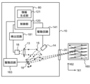
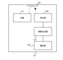
- FIG. 1 is a diagram illustrating the configuration of a distance measuring device 10 according to the first embodiment.
- FIG. 2 is a diagram illustrating the distance measuring device 10 according to this embodiment.
- dashed arrows schematically indicate paths of light.
- a distance measuring device 10 according to this embodiment is a device that emits light output from a light source 14 through a transmission member 20 and detects reflected light from an object 30 .
- the distance measuring device 10 has a light receiving section 180 and an information generating section 121 .
- the light receiving section 180 receives at least internally reflected light including reflected light reflected by the transmissive member 20 .
- the information generator 121 uses the result of the light reception of the internally reflected light by the light receiver 180 to generate information (hereinafter referred to as "ranging information”) regarding the ranging performance of the ranging device 10 .
- ranging information information regarding the ranging performance of the ranging device 10 .
- the light emitted from the light source 14 is emitted to the outside of the distance measuring device 10 mainly through the transmission member 20 as shown in FIG.
- at least part of the light output from the light source 14 is reflected inside the distance measuring device 10 as shown in FIG. 1 and becomes internally reflected light.
- the internally reflected light is received by the light receiving section 180 .
- This internally reflected light includes the light reflected by the transmissive member 20 .
- the reflected light due to the deposit is included in the internally reflected light.
- the transmission member 20 is a member that separates the inside and outside of the distance measuring device 10 and that transmits light.
- Transmissive member 20 is made of, for example, glass or resin. At least one surface of the transmissive member 20 is exposed to the space outside the range finder 10, and dirt, raindrops, and the like may adhere to it.
- the reflected light caused by the deposit includes, for example, light reflected at the interface between the transmissive member 20 and the deposit, light reflected inside the deposit, and light reflected at the interface between the deposit and air. include.
- the information generation unit 121 can generate distance measurement information using such a result of receiving the internally reflected light.
- the distance measurement information is, for example, information indicating the distance measurement performance, and is information related to the received light intensity of the reflected light from the object 30 and the distance measurement limit distance.
- the distance measurement information can be deterioration information indicating the degree of deterioration of the distance measurement performance with respect to the reference state.
- the distance measurement information may be information indicating the level of the distance measurement performance. It is assumed that the object 30 is not attached to the transmissive member 20 , that is, is not in contact with the transmissive member 20 .
- FIG. 3 is a diagram illustrating in detail the configuration of the distance measuring device 10 according to this embodiment.
- dashed arrows schematically indicate paths of light.
- the configuration of the distance measuring device 10 will be described in detail with reference to this figure.
- Distance measuring device 10 measures the distance between distance measuring device 10 and an object (target object 30) within scanning range 160 based on, for example, the difference between the emission timing of pulsed light and the reception timing of reflected light (reflected pulsed light). It is a device for measuring distance.
- the pulsed light is light such as infrared light, for example.
- the pulsed light is, for example, a laser pulse.
- the pulsed light emitted from the light source 14 provided in the distance measuring device 10 and emitted to the outside of the distance measuring device 10 through the transmission member 20 is reflected by an object and at least part of it is directed toward the distance measuring device 10. return. Then, the reflected light passes through the transmission member 20 again and enters the distance measuring device 10 .
- the reflected light incident on the distance measuring device 10 is received by the light receiving section 180 and its intensity is detected.
- Light receiving section 180 includes light receiving element 18 and detection circuit 181 .
- the distance measuring device 10 measures the time from when the pulsed light is emitted from the light source 14 to when the reflected light is detected by the light receiving section 180 .
- the control unit 120 provided in the distance measuring device 10 calculates the distance between the distance measuring device 10 and the object using the measured time and the propagation speed of the pulsed light.
- the ranging device 10 is, for example, a lidar (LIDAR: Laser Imaging Detection and Ranging, Laser Illuminated Detection and Ranging or LiDAR: Light Detection and Ranging) device.
- the light source 14 emits pulsed light.
- Light source 14 is, for example, a laser diode.
- the light receiving element 18 receives the pulsed light incident on the distance measuring device 10 and the internal reflected light described above.
- Light receiving element 18 is, for example, a photodiode such as an avalanche photodiode (APD).
- the light-receiving element 18 includes a light-receiving element for receiving internally reflected light and using it for generating distance measurement information, and a light-receiving element for receiving reflected light from the object 30 and measuring the distance.
- An example that is also used is explained.
- the light-receiving element for receiving the internally reflected light and using it for determination of adhering matter and the light-receiving element for receiving the reflected light from the object 30 and measuring the distance may be provided separately.
- the distance measuring device 10 further includes a movable mirror 16.
- the movable mirror 16 is, for example, a uniaxially movable or biaxially movable MEMS mirror. By changing the orientation of the reflecting surface of the movable mirror 16, the emission direction of the pulsed light emitted from the distance measuring device 10 can be changed.
- the movable mirror 16 is a biaxially movable MEMS mirror, by biaxially driving the movable mirror 16, raster scanning can be performed within a predetermined range with pulsed light.
- the control unit 120 generates point cloud data including measurement results using a plurality of pulsed lights. For example, when raster scanning is performed within the scanning range 160 , linear scanning is performed by changing the light emission direction to the first direction 161 . By performing a plurality of linear scans while changing the light emitting direction in the second direction 162, point cloud data including a plurality of measurement results within the scanning range 160 can be generated.
- the first direction 161 and the second direction 162 are orthogonal.
- a unit of point cloud data generated by a single raster scan is called a frame. After the measurement of one frame is finished, the direction of light emission returns to the initial position, and the measurement of the next frame is performed. Thus, repeating frames are generated.
- distances measured by pulsed light are associated with information indicating the emission direction of the pulsed light.
- the point cloud data may include three-dimensional coordinates indicating reflection points of the pulsed light.
- the control unit 120 generates point cloud data using the calculated distance and information indicating the angle of the movable mirror 16 when emitting each pulsed light.
- the generated point cloud data may be output to the outside of the distance measuring device 10 or may be held in a storage device accessible from the control unit 120 .
- the distance measuring device 10 further includes a mirror 15 with a hole and a condenser lens 13 .
- the pulsed light emitted from the light source 14 passes through the hole of the mirror 15 with a hole, is reflected by the movable mirror 16 , and is emitted from the distance measuring device 10 .
- the reflected light incident on the distance measuring device 10 is reflected by the movable mirror 16 and the holed mirror 15 , and then enters the light receiving section 180 via the condenser lens 13 .
- the distance measuring device 10 may further include a collimating lens, a mirror, and the like.
- the control section 120 can control the light emitting section 140, the light receiving section 180, and the movable reflecting section 164 (see FIG. 4).
- Light emitting unit 140 includes light source 14 and drive circuit 141 .
- Movable reflector 164 includes movable mirror 16 and drive circuit 163 .
- the drive circuit 141 is a circuit for causing the light source 14 to emit light based on the control signal from the integrated circuit 80, and includes, for example, a switching circuit and a capacitive element.
- the detection circuit 181 includes an IV converter and an amplifier, and outputs a signal indicating the intensity of light detected by the light receiving element 18 .
- the control unit 120 acquires a light receiving signal from the light receiving unit 180 and calculates the distance from the distance measuring device 10 to the object within the scanning range 160 as described above.
- the information generator 121 also acquires the light reception signal from the light receiver 180 and uses it to generate positive distance measurement information.
- FIG. 4 is a diagram illustrating the hardware configuration of the control unit 120 and the information generation unit 121 according to this embodiment.
- the controller 120 and the information generator 121 are implemented using an integrated circuit 80 .
- the integrated circuit 80 is, for example, an SoC (System On Chip).
- the integrated circuit 80 has a bus 802 , a processor 804 , a memory 806 , a storage device 808 , an input/output interface 810 and a network interface 812 .
- a bus 802 is a data transmission path for the processor 804, memory 806, storage device 808, input/output interface 810, and network interface 812 to transmit and receive data to and from each other.
- the processor 804 is an arithmetic processing device implemented using a microprocessor or the like.
- a memory 806 is a memory implemented using a RAM (Random Access Memory) or the like.
- the storage device 808 is a storage device implemented using ROM (Read Only Memory), flash memory, or the like.
- the input/output interface 810 is an interface for connecting the integrated circuit 80 with peripheral devices.
- an input/output interface 810 is connected to a drive circuit 141 for the light source 14, a detection circuit 181 for the light receiving element 18, and a drive circuit 163 for the movable mirror 16.
- a network interface 812 is an interface for connecting the integrated circuit 80 to a communication network.
- This communication network is, for example, a CAN (Controller Area Network), Ethernet, LVDS (Low Voltage Differential Signaling), or the like.
- a method for connecting the network interface 812 to the communication network may be a wireless connection or a wired connection.
- the storage device 808 stores program modules for realizing the functions of the control unit 120 and the information generation unit 121 .
- the processor 804 implements the functions of the control unit 120 and the information generation unit 121 by reading this program module into the memory 806 and executing it.
- the hardware configuration of the integrated circuit 80 is not limited to the configuration shown in this figure.
- program modules may be stored in memory 806 .
- integrated circuit 80 may not include storage device 808 .
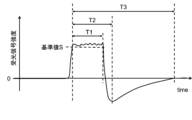
- FIGS. 5 and 6 are diagrams exemplifying received light signal waveforms of internally reflected light when the transmissive member 20 has adhering matter.
- the information generator 121 can specify, for example, the waveform of the received light signal at the light receiving unit 180 within a predetermined time from the emission of the light as the waveform of the internally reflected light.
- the information generating section 121 may consider the pulsed light received first after the pulsed light is emitted to be the internally reflected light. This is because the internally reflected light is reflected from a fixed short distance.
- the received light signal waveform of the internally reflected light differs depending on the type of the adhering matter, such as whether the adhering matter is water, oil, dust, or the like.
- the information generation unit 121 generates distance measurement information using the characteristics of the received light signal waveform. Further, as described above, the distance measuring device 10 performs distance measurement by sequentially emitting a plurality of lights. The information generator 121 then generates distance measurement information for each light emission. The generation of distance measurement information will be described in detail below.
- the information generation unit 121 can generate distance measurement information, for example, using the intensity of the internally reflected light in the light reception result.
- the intensity of the internally reflected light is increased by being reflected by the adhering substance.
- the received light intensity is particularly high, it exceeds the detection range of the light receiving section 180, and the received light signal may be saturated as shown in FIGS.
- the reflected light from the object 30 is also attenuated, so the distance measurement performance is deteriorated. Therefore, it can be said that the greater the intensity of the internally reflected light, the lower the distance measurement performance.
- the information generation unit 121 specifies the maximum intensity of the light reception signal of the internally reflected light for each emitted light as the intensity of the internally reflected light, and uses it to generate distance measurement information.
- the information generation unit 121 can generate distance measurement information using, for example, the length of time related to the saturation of the light receiving unit 180 by the internally reflected light.
- the waveform will be subject to saturation over time.
- the light receiving section 180 receives the reflected light from the object 30 after receiving the internally reflected light.
- the reception of the reflected light from the object 30 may also be affected. For example, if the reflected light from the object 30 enters the light receiving element 18 before the light receiving signal returns to the reference level after saturation, the peak may not be detected accurately. Then, the distance to the object 30 cannot be calculated correctly. Therefore, it can be said that there is a tendency that the longer the length of time related to saturation, the lower the ranging performance.
- Time lengths related to saturation that can be used for determination include, for example, times T1, T2, and T3 shown in FIGS. Note that the length of time related to saturation is hereinafter simply referred to as "saturation time".
- the saturation time is at least one of times T1, T2, and T3.
- the information generator 121 may use only one of the times T1, T2, and T3, or may use a combination of two or more. Each of the times T1, T2, and T3 will be discussed in detail below.
- the time T1 is the length of time during which the light receiving section 180 is saturated.
- the information generation unit 121 determines that the light receiving unit 180 is saturated when the light receiving signal output from the light receiving unit 180 exceeds a predetermined reference value S, and measures the time T1.
- the reference value S is, for example, slightly smaller than the saturation level of the light receiving element.
- the saturation level means the maximum amount of light that can be detected without saturating the light receiving section 180 .
- the time T2 is the length of time starting from the point at which saturation begins in the output waveform of the light receiving section 180 and ending at the point at which the slope becomes zero for the first time after saturation.
- the information generation unit 121 determines that the saturation starts when the light receiving signal output from the light receiving unit 180 exceeds the reference value S described above after the pulsed light is emitted. Further, the information generator 121 calculates the slope at each point of the waveform, detects the point in time when the calculated slope becomes zero, and measures the time T2.
- Time T3 is the length of time from the point at which saturation begins in the output waveform of the light receiving section 180 to the point at which zero crosses the second time after saturation or the point at which it converges for the first time after saturation, whichever is earlier. be.
- the information generation unit 121 determines that the saturation starts when the light receiving signal output from the light receiving unit 180 exceeds the reference value S described above after the pulsed light is emitted.
- the information generator 121 detects the point in time when the received light signal crosses zero, and specifies the point in time when the light-receiving signal crosses zero for the second time after saturation.
- the information generation unit 121 determines that the signal value is in a convergence state when a state in which the signal value is within a predetermined convergence level range continues for a predetermined length.
- the point at which that state begins that is, the point at which the signal value changes from outside the convergence level range to within the convergence level range is regarded as the first convergence point after saturation. Identify.
- the convergence level range is a range including zero in between, the upper limit of the convergence level range is slightly greater than zero, and the lower limit of the convergence level range is slightly less than zero.
- the difference between the upper convergence level range and zero can be greater than the difference between the lower convergence level range and zero. This is because, for example, when disturbance light is incident on the distance measuring device 10, the received light signal may converge to a level greater than zero due to the disturbance light.
- the information generator 121 selects the earlier of the second zero-crossing point after saturation and the first convergence point after saturation, and measures time T3. It is not necessary that either the second zero-crossing point after saturation or the first convergence point after saturation does not exist. In this case, the information generation unit 121 determines the end point of T3 to be the end point of T3, whichever can be specified, out of the second zero-crossing point after saturation and the first convergence point after saturation. In the example of FIG. 6, T2 and T3 are the same.
- the end point of time T3 may be the first point in time when the received light signal is within the convergence level range and the slope of the received light signal is within a predetermined range including zero after the end of the saturated state.
- the information generator 121 generates distance measurement information using the amount of change from the initial value for the intensity and saturation time of the internally reflected light. By doing so, the influence of deposits can be more accurately identified.
- the initial value it is possible to use a value measured in a state in which there is no deposit on the transmissive member 20, for example, in a shipping state.
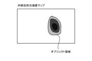
- the information generation unit 121 identifies an object region corresponding to a region in which an adhering matter is present on the transmissive member 20 by using the distribution of light reception results of internally reflected light in a plurality of light emission directions, and Ranging information can be generated based on the position at .
- FIG. 7 is a diagram schematically showing the distribution of the internal reflected light intensity within the frame.
- the information generation unit 121 can generate such an internal reflected light intensity map using internal reflected light intensities corresponding to a plurality of emission directions. As described above, the internal reflected light intensity used here is preferably the amount of change from the initial value. From the internal reflected light intensity map, it is possible to identify the area where the deposit is generated in the scanning range. Specifically, the information generation unit 121 identifies, as an object area, an area where the internal reflected light intensity is equal to or greater than a predetermined value in the internal reflected light intensity map.
- the distance measurement capability of the distance measuring device 10 also depends on the relationship between the position of the adhering matter and the emission direction. For example, light emitted toward the center of the deposit is affected more by the deposit than light emitted toward the edge of the deposit. In other words, the influence on distance measurement is also increased. Therefore, the information generation unit 121 can generate distance measurement information based on the position within the object area. Specifically, the information generation unit 121 calculates the shortest distance from the outer edge of the object area for each point (radiation direction) within the identified object area. It can be said that the longer the shortest distance, the closer the point is to the center of the object area, and the easier it is for the distance measurement to deteriorate. For points outside the object area, a sufficiently large default value is set as the shortest distance.
- the information generation unit 121 generates a saturation time map using saturation times corresponding to a plurality of emission directions or the amount of change from the initial value of the saturation time, instead of the internal reflected light intensity map, and generates a saturation time map. may be used to identify the
- the information generation unit 121 performs determination based on a rule based on the result of receiving the internally reflected light, and generates distance measurement information.
- the information generation unit 121 performs the following processing each time measurement of one frame is completed, and generates distance measurement information for each measurement point within that frame.
- the information generating section 121 may generate the distance measurement information for each light emission.
- FIG. 8 is a table illustrating determination rules for generating distance measurement information from the result of receiving internally reflected light.
- FIG. 9 is a flowchart illustrating the flow of determination by the information generator 121 when using the determination rule of FIG.
- the information generation unit 121 generates distance measurement information using the internal reflected light intensity, the saturation time, and the shortest distance from the outer edge of the object region.
- the information generation unit 121 generates a deterioration prediction level as distance measurement information.
- the degree of deterioration increases in the order of "deterioration level C", "deterioration level B", and "deterioration level A".
- the information generation unit 121 determines whether or not the internal reflected light intensity at the determination target point is greater than or equal to the reference value S (S101). When the internal reflected light intensity is not equal to or greater than the reference value S (No in S101), the information generator 121 determines that the deterioration prediction level at that point is "standard" (S102). When the internal reflected light intensity is equal to or greater than the reference value S (Yes in S101), the information generation unit 121 then determines whether the saturation time of the determination target point is equal to or greater than the reference value A (S103).
- the information generator 121 determines the deterioration prediction level at that point to be "deterioration level A" (S104). If the saturation time is greater than or equal to the reference value A (Yes in S103), the information generation unit 121 then determines whether the shortest distance from the outer edge of the object region of the determination target point is greater than or equal to the reference value B ( S105). If the shortest distance is not equal to or greater than the reference value B (No in S105), the information generator 121 determines the predicted deterioration level of that point to be "deterioration level B" (S106).
- the information generator 121 determines the predicted deterioration level of that point to be "deterioration level C" (S107). Thus, the information generator 121 can specify the deterioration level on a rule basis.
- the information generation unit 121 may generate information regarding distance measurement using a determination rule provided for each configuration of the optical system of the distance measuring device 10 . Since the effect of adhering matter on distance measurement performance differs depending on the configuration of the optical system, it is preferable to use a suitable determination rule for each configuration. The fact that the configuration of the optical system affects the distance measurement performance differently will be described below.
- FIG. 10(a) is a diagram schematically showing the transmissive member 20 of the distance measuring device 10 with no telephoto lens attached
- FIGS. 10(b) and 10(c) with the telephoto lens attached
- 4 is a diagram schematically showing a transmissive member 20 of the distance measuring device 10;
- FIG. 10(a) to 10(c) a broken-line rectangle 210 indicates the effective scanning area
- a solid-line rectangle 211 indicates the spot shape and size of the light emitted from the distance measuring device 10 on the transmissive member 20.
- an ellipse 212 indicate the shape and size of the light receiving spot on the transmissive member 20 .
- the effective scanning area is an area through which emitted light can pass in the transmissive member 20 when performing scanning for generating one frame.
- the light-receiving spot is an area capable of receiving light that is emitted from the distance measuring device 10 and reflected by the object 30 and then incident on the distance measuring device 10 .
- the size of the light spot with respect to the effective scanning area varies greatly depending on the presence or absence of the telephoto lens.
- FIG. 11 is a diagram showing the results of measurement with an adhering matter attached to the transmissive member 20 of the distance measuring device 10 to which no telephoto lens is attached.
- 12A and 12B are diagrams showing the results of measurement in a state in which an adhering matter is attached to the transmissive member 20 of the distance measuring device 10 to which a telephoto lens is attached.
- 10(a) and 10(c) show the size and shape of the deposit 213 at this time.
- 11 and 12 respectively show an internal reflected light intensity map, a saturation time map, a ranging intensity map, and a distance map obtained in the same frame.
- the internal reflected light intensity map and saturation time map are as described above.
- the ranging intensity map is a map showing the distribution of the peak intensity of the received light signal when the reflected light from the object 30 is received.
- the distance map is a map showing the distribution of distances to the object 30 calculated by receiving reflected light from the object 30 .
- each map there is an area corresponding to deposits inside the dashed ellipse. 11 and 12 are the same in size.
- the contaminants that are assumed to be attached are raindrops, dust, insects, snow, etc., and their sizes are generally several millimeters. Assuming this size, the size of the deposit used in the measurements of FIGS. 11 and 12 was set to 2 mm ⁇ 3 mm.
- the influence of the deposit appears in the shape close to the actual shape in the internal reflected light intensity map and the saturation time map. Also, in the ranging intensity map and the distance map, it appears that the ranging was impossible in the area where the adhering matter existed.
- the influence appears in a large area with respect to the frame in the internal reflected light intensity map. This is due to the large size of the deposit relative to the effective scanning area. In the saturated time map, the effect decreases from the center of the object area to the outer edge. Also, in the distance measurement intensity map, a strong effect can be seen in the center of the object area, but in the distance map, there are many parts where the effect does not appear, and it can be seen that the distance can be measured over the entire frame. This is believed to be due to the fact that the spot of light and the deposit are of similar size.
- the information generating unit 121 acquires, for example, information indicating the configuration of the optical system input in advance to 10, and reads out and uses the determination rule corresponding to the configuration from the storage unit.
- the image is distorted due to the orbit of the movable mirror 16 and the effect of the optical lens. Since such distortion is known, a process of correcting each map using a predetermined correction parameter may be performed. In that case, the outline of the map need not be rectangular. Alternatively, the outer shape of the map may remain rectangular, and processing may be performed to correct the distortion of the projected object or the like as necessary. The same applies to the deterioration map, which will be described later.
- the information generation unit 121 may generate a ranging map showing the distribution of the ranging information. Further, the distance measuring device 10 may generate and output display data for displaying the generated distance map as an image. The ranging device 10 can display a ranging map by outputting display data to a display. Note that the distance measuring device 10 may store the generated distance measuring property information in a storage unit accessible from the distance measuring device 10 . This storage unit may or may not be included in the distance measuring device 10 .
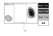
- FIG. 13 is a diagram illustrating an image displaying a distance map.
- a degradation map of ranging performance is displayed as a ranging map.
- a table is also displayed showing what range-finding limit distances each deterioration level corresponds to under a plurality of conditions.
- Such a table can be prepared by preliminary experimental measurements and stored in the storage unit. For example, in this example, it can be seen that the critical distance at which a target with 100% reflectance can be measured with a background light of 100 klux is 30 m in the region of deterioration level C in the frame.
- FIG. 14 is a flowchart illustrating the flow of the information generation method according to this embodiment.
- the information generating method according to the present embodiment is executed by a computer to generate distance measurement information of the distance measuring device 10 that emits light output from a light source through a transparent member and detects reflected light from an object. It is an information generation method for In this method, the light receiving result of the internally reflected light is acquired by the light receiving unit that receives at least the internally reflected light including the reflected light reflected by the transmissive member 20 (S500). Then, using the result of receiving the internally reflected light, distance measurement information of the distance measuring device 10 is generated (S510).
- the information generating section 121 generates the distance measuring performance information of the distance measuring device 10 using the light receiving result of the internally reflected light by the light receiving section 180 . Therefore, it is possible to identify the influence of deposits on the output window of the range finder on the range finder, confirm whether the user meets the required range finder performance, and take necessary measures. .
- the distance measuring device 10 according to the second embodiment is similar to the distance measuring device 10 according to the first embodiment, except that the information generation unit 121 generates the distance measurement information using the learned model 40 by machine learning. Same as device 10 . A detailed description is given below.
- the information generation unit 121 uses the model 40 instead of using the determination rule to generate distance measurement information from the result of receiving the internally reflected light.
- the model 40 is a model that receives, for example, the result of receiving internally reflected light as an input and outputs distance measurement information.
- FIG. 15 is a diagram exemplifying the learned model 40 used by the information generation unit 121 according to the second embodiment.
- the information generation unit 121 acquires the learned model 40 by reading it from a storage unit accessible from the information generation unit 121 .
- the information generator 121 inputs input data to the model 40 and obtains output data of the model 40 .
- the input data to be input to the model 40 may be the waveform of the internally reflected light, the intensity of the internally reflected light, the saturation time, the shortest distance from the outer edge of the object area, or a vector containing them.
- Input data for the model 40 may also include, for example, an internal reflection intensity map and a saturation time map.
- the output data of model 40 is, for example, the predicted deterioration level of each point in the frame.
- the output data may be a map, such as a degradation map.
- the input data and output data of the model 40 may be measured point by measurement point or frame by frame.
- the input data of the model 40 may further include information indicating the configuration of the distance measuring device 10 when the light reception result is obtained.
- the configuration of distance measuring device 10 includes, for example, the configuration of an optical system.
- the model 40 may be provided for each configuration of the distance measuring device 10 .
- the information generating section 121 acquires information indicating the configuration of the distance measuring device 10, reads out the model 40 corresponding to the configuration from the storage section, and uses it.
- the trained model 40 includes a neural network 410.
- the learned model 40 is a model that has undergone machine learning in advance using a plurality of training data.
- the information generation unit 121 can improve the accuracy of the distance measurement information.
- the information generating unit 121 may combine the rule-based determination as described in the first embodiment and the determination using the model 40 to generate range finding information.
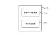
- FIG. 16 is a block diagram illustrating the functional configuration of an apparatus that generates models.
- the model generation device 70 includes a training data acquisition section 710 and a model generation section 720 .
- the training data acquisition unit 710 acquires training data in which the result of receiving the internally reflected light and the range finding information of the range finder are associated with each other.
- the result of receiving the internally reflected light includes the reflected light reflected by the transmitting member 20 in a distance measuring device that emits the light output from the light source 14 through the transmitting member 20 and detects the reflected light from the object. This is the result of receiving internal reflected light.
- the model generation unit 720 performs machine learning using training data to generate the model 40 that receives the result of receiving the internally reflected light as an input and outputs distance measurement information.
- a plurality of training data can be prepared by preliminary experimental measurements and stored in the storage unit.
- the training data acquisition unit 710 acquires the training data by reading it from the storage unit, for example.
- the range finder 10 according to the third embodiment is similar to the range finder 10 according to at least one of the first and second embodiments, except that the control unit 120 performs control using range finding information. are the same.
- the control unit 120 controls at least one of the output intensity of the light source 14 and the multiplication factor of the light receiving unit 180 based on the range finding information. A detailed description is given below.
- the control unit 120 When a range map is generated for a certain frame, the control unit 120 performs control based on the generated range map when measuring subsequent frames. Specifically, when measuring in a certain emission direction, the control unit 120 specifies the distance measurement information for that emission direction by referring to the distance measurement map. Then, at least one of the output intensity of the light source 14 and the multiplication factor of the light receiving section 180 is controlled based on the specified range finding information. For example, the information generation unit 121 increases the output intensity of the light source 14 as the degree of deterioration indicated by the range finding information increases. By doing so, even if the light is attenuated by the adhering matter, light of sufficient intensity can be output from the distance measuring device 10 .
- the information generation unit 121 increases the multiplication factor of the light receiving unit 180 as the degree of deterioration indicated in the range finding information is higher. By doing so, even when the reflected light from the object 30 is weak, a sufficiently strong received light signal can be obtained.
- the control unit 120 acquires reference information from a storage unit accessible from the control unit 120 and uses it for control.
- the reference information is information that associates the deterioration level with the output intensity of the light source 14 or information that associates the deterioration level with the multiplication factor of the light receiving section 180 .
- the control unit 120 specifies the output intensity or the multiplication factor corresponding to the deterioration level indicated by the range finding information, and controls the light source 14 or the light receiving unit 180 .
- control unit 120 controls at least one of the output intensity of the light source 14 and the multiplication factor of the light receiving unit 180 based on the range finding information. Therefore, it is possible to perform good distance measurement even when there is an influence of adhering matter.
- FIG. 17 is a block diagram illustrating the functional configuration of the distance measuring device 10 according to the fourth embodiment.
- the distance measuring device 10 according to this embodiment is the same as the distance measuring device 10 according to at least one of the first to third embodiments, except that it further includes a notification unit 123 that performs notification using distance measurement information.
- the notification unit 123 acquires information indicating the notification target area in the distance measurement map, and performs notification based on the distance measurement information of the notification target area. A detailed description is given below.
- the notification is, for example, a warning indicating that the ranging performance has deteriorated.
- the notification unit 123 issues a warning about deterioration of the distance measurement performance within the notification target area, but does not consider the distance measurement information outside the notification target area in the notification. In other words, even when the distance measurement performance deteriorates outside the notification target area, the notification unit 123 does not issue a warning or the like.
- FIG. 18 is a diagram for explaining the notification target area 61.
- FIG. A user designates in advance a notification target area 61 in a frame for the distance measuring device 10 according to the present embodiment.
- Range finder 10 receives an input designating notification target area 61 from the user.
- the notification unit 123 acquires information indicating the notification target area 61 input to the distance measuring device 10 .
- the reporting unit 123 acquires the ranging map from the information generating unit 121 when the ranging map is generated. Then, the notification unit 123 determines whether deterioration of the ranging performance is found in the notification target area 61 in the ranging map. If deterioration in distance measurement performance is found within the notification target area 61, the notification unit 123 outputs a warning.
- the notification unit 123 when no degradation of distance measurement performance is found within the notification target area 61, the notification unit 123 does not output a warning. Degradation of the ranging performance is found within the notification target area 61 in the ranging map, for example, when at least part of the deterioration prediction level within the notification target area 61 is not "standard". Alternatively, it is a case where the deterioration prediction level of at least a part of the notification target area 61 is worse than a predetermined level. Further, the notification unit 123 does not output a warning even when deterioration of the distance measurement performance is found outside the notification target area 61 as shown in FIG. 18 .
- the notification unit 123 can output the warning by, for example, voice output or display on the display.
- the notification unit 123 acquires the conditions input by the user. For example, the user sets "background light of 0 lux" and “target reflectance of 10%” as the usage environment information, and inputs the condition of "distance measurement limit distance of 30 m or more" as the required performance condition. Then, when the notification unit 123 no longer satisfies the condition of "having a distance measurement limit distance of 30 m or more for measurement with a background light of 0 lux and a target reflectance of 10%" in at least a part of the notification target area 61, Print a warning. Whether or not the set conditions are satisfied can be determined using a table such as that shown in FIG. 13, for example, in addition to the generated distance measurement information.
- the notification unit 123 indicates that the ranging performance is good when no degradation of the ranging performance is seen within the notification target area 61. You may notify us.
- the storage device 808 further stores program modules for realizing the function of the notification unit 123.
- the processor 804 implements the function of the notification unit 123 by reading this program module into the memory 806 and executing it.
- the range finder 10 further includes the notification unit 123 that performs notification using the range finding information. Therefore, it is easy for the user to grasp the deterioration of the ranging performance.
- FIG. 19 is a block diagram illustrating the configuration of an information generation device 50 according to the fifth embodiment.
- the information generation device 50 according to the present embodiment emits the light output from the light source 14 through the transmission member 20 and generates distance measurement information of the distance measurement device 10 that detects the reflected light from the target object 30. It is an information generating device that The information generation device 50 includes an information generation section 510 .
- the information generation unit 510 generates distance measurement information of the distance measuring device 10 using the result of receiving the internally reflected light by the light receiving unit 180 that receives at least the internally reflected light including the reflected light reflected by the transmissive member 20 . . A detailed description is given below.
- the distance measuring device 10 is the same as the distance measuring device 10 according to at least one of the first to third embodiments, except that the information generation unit 121 is not provided.
- the range finder 10 according to this embodiment is the same as the range finder 10 according to the fourth embodiment, except that the information generation unit 121 and the notification unit 123 are not provided.
- the information generation device 50 according to the present embodiment acquires information necessary for generating distance measurement information from the distance measurement device 10 and generates the information.
- the information generation device 50 includes an information generation section 510 .
- the information generator 510 performs the same processing as the information generator 121 according to the first or second embodiment.
- the information generation device 50 may further include a notification unit similar to the notification unit 123 according to the fourth embodiment.
- the information generating device 50 acquires information indicating the result of receiving the internally reflected light from the distance measuring device 10 . Then, the information generating section 510 generates distance measuring performance information of the distance measuring device 10 based on the information indicating the result of receiving the internally reflected light.
- the generated distance measurement information may be output from the information generation device 50 to the distance measurement device 10 and used for control by the control unit 120, or may be output from the information generation device 50 to a display or the like. Further, the generated distance measurement information may be held in a storage accessible from the information generation device 50 .
- This storage unit may be a storage unit included in information generation device 50 (for example, storage device 908 described later), or may be a storage unit provided outside information generation device 50 .
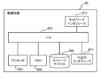
- FIG. 20 is a diagram illustrating the hardware configuration of the information generation device 50 according to this embodiment.
- the information generation device 50 is implemented using an integrated circuit 90 .
- the integrated circuit 90 is, for example, an SoC (System On Chip).
- the integrated circuit 90 has a bus 902 , a processor 904 , a memory 906 , a storage device 908 , an input/output interface 910 and a network interface 912 .
- a bus 902 is a data transmission path for the processor 904, memory 906, storage device 908, input/output interface 910, and network interface 912 to transmit and receive data to and from each other.
- the processor 904 is an arithmetic processing device implemented using a microprocessor or the like.
- a memory 906 is a memory implemented using a RAM (Random Access Memory) or the like.
- the storage device 908 is a storage device implemented using a ROM (Read Only Memory), flash memory, or the like.
- the input/output interface 910 is an interface for connecting the integrated circuit 90 with peripheral devices.
- the rangefinder 10 is connected to the input/output interface 910 .
- a network interface 912 is an interface for connecting the integrated circuit 90 to a communication network.
- This communication network is, for example, a CAN (Controller Area Network) communication network.
- a method for connecting the network interface 912 to the communication network may be a wireless connection or a wired connection.
- the storage device 908 stores program modules for realizing the functions of the information generation unit 510 .
- the processor 904 implements the function of the information generator 510 by reading this program module into the memory 906 and executing it. Also, the storage device 908 may further store a program module for implementing the notification unit.
- the hardware configuration of the integrated circuit 90 is not limited to the configuration shown in this figure.
- program modules may be stored in memory 906 .
- integrated circuit 90 may not include storage device 908 .
Landscapes
- Physics & Mathematics (AREA)
- Engineering & Computer Science (AREA)
- General Physics & Mathematics (AREA)
- Radar, Positioning & Navigation (AREA)
- Remote Sensing (AREA)
- Electromagnetism (AREA)
- Computer Networks & Wireless Communication (AREA)
- Optical Radar Systems And Details Thereof (AREA)
Abstract
One of the problems the present invention addresses is identifying how a substance adhering to an emission window of a range measuring device affects the range-measuring performance of the range measuring device. A range measuring device (10) projects light, which is outputted from a light source (14), through a transmitting member (20), and detects the light reflected from an object. The range measuring device (10) comprises a light-receiving unit (180) and an information generation unit (121). The light-receiving unit (180) at least receives internal reflected light that includes light reflected from the transmission member (20). The information generation unit (121) uses the results of the reception of the internal reflected light by the light-receiving unit (180) to generate information about the range-measuring performance of the range measuring device (10).
Description
本発明は、測距装置、モデル生成装置、情報生成装置、情報生成方法、およびプログラムに関する。
The present invention relates to a distance measuring device, a model generation device, an information generation device, an information generation method, and a program.
近年、自動車の自動運転等に用いることができる測距装置の開発が行われている。測距装置の一例としては、出射した光が物体に反射されて戻るまでの時間を測定して、周囲の物体との距離を測定するものが挙げられる。
In recent years, the development of distance measuring devices that can be used for automatic driving of automobiles, etc. is underway. An example of a rangefinder is one that measures the time it takes for emitted light to be reflected by an object and return to measure the distance to surrounding objects.
このような測距装置では、光を出射する出射窓に付着物が生じると測距に影響が生じる。
With such a distance measuring device, if there is an adhering matter on the exit window through which the light is emitted, the distance measurement will be affected.
特許文献1には、光の受光パワーをモニタし、窓部から汚れなどを取り除くことが必要なときに窓洗浄装置を動作させることが記載されている。
Patent Literature 1 describes monitoring the light reception power and operating the window cleaning device when it is necessary to remove dirt from the window.
付着物による測距性への影響は、測距装置の構成によっても異なる。測距にどのような影響が生じているかを特定することにより、適切な対応を取ることができる。
The effect of adhering matter on distance measurement varies depending on the configuration of the distance measuring device. Appropriate action can be taken by identifying how ranging is affected.
本発明が解決しようとする課題としては、測距装置の出射窓に生じた付着物による、測距性への影響を特定することが一例として挙げられる。
One example of the problem to be solved by the present invention is to identify the effect of deposits on the output window of the rangefinder on the rangefinder performance.
請求項1に記載の発明は、
光源から出力された光を、透過部材を介して出射し、対象物からの反射光を検出する測距装置であって、
前記透過部材で反射した反射光を含む内部反射光を少なくとも受光する受光部と、
前記受光部による前記内部反射光の受光結果を用いて、当該測距装置の測距性に関する情報を生成する情報生成部とを備える測距装置である。 The invention according toclaim 1,
A distance measuring device that emits light output from a light source through a transparent member and detects reflected light from an object,
a light receiving unit that receives at least internally reflected light including reflected light reflected by the transmissive member;
and an information generation unit that generates information on the distance measuring performance of the distance measuring device using the result of light reception of the internally reflected light by the light receiving unit.
光源から出力された光を、透過部材を介して出射し、対象物からの反射光を検出する測距装置であって、
前記透過部材で反射した反射光を含む内部反射光を少なくとも受光する受光部と、
前記受光部による前記内部反射光の受光結果を用いて、当該測距装置の測距性に関する情報を生成する情報生成部とを備える測距装置である。 The invention according to
A distance measuring device that emits light output from a light source through a transparent member and detects reflected light from an object,
a light receiving unit that receives at least internally reflected light including reflected light reflected by the transmissive member;
and an information generation unit that generates information on the distance measuring performance of the distance measuring device using the result of light reception of the internally reflected light by the light receiving unit.
請求項12に記載の発明は、
光源から出力された光を、透過部材を介して出射し、対象物からの反射光を検出する測距装置において、前記透過部材で反射した反射光を含む内部反射光を受光部で受光した、受光結果と、当該測距装置の測距性に関する情報とが関連付けられた訓練データを取得する訓練データ取得部と、
前記訓練データを用いた機械学習を行うことにより、前記内部反射光の受光結果を入力とし前記測距性に関する情報を出力とするモデルを生成するモデル生成部とを備える、
モデル生成装置である。 The invention according toclaim 12,
A distance measuring device that emits light output from a light source through a transparent member and detects reflected light from an object, wherein a light receiving unit receives internally reflected light including reflected light reflected by the transparent member, a training data acquisition unit that acquires training data in which the received light result is associated with information about the distance measurement capability of the range finder;
a model generation unit that generates a model that receives the result of receiving the internally reflected light and outputs information about the distance measurement by performing machine learning using the training data;
It is a model generator.
光源から出力された光を、透過部材を介して出射し、対象物からの反射光を検出する測距装置において、前記透過部材で反射した反射光を含む内部反射光を受光部で受光した、受光結果と、当該測距装置の測距性に関する情報とが関連付けられた訓練データを取得する訓練データ取得部と、
前記訓練データを用いた機械学習を行うことにより、前記内部反射光の受光結果を入力とし前記測距性に関する情報を出力とするモデルを生成するモデル生成部とを備える、
モデル生成装置である。 The invention according to
A distance measuring device that emits light output from a light source through a transparent member and detects reflected light from an object, wherein a light receiving unit receives internally reflected light including reflected light reflected by the transparent member, a training data acquisition unit that acquires training data in which the received light result is associated with information about the distance measurement capability of the range finder;
a model generation unit that generates a model that receives the result of receiving the internally reflected light and outputs information about the distance measurement by performing machine learning using the training data;
It is a model generator.
請求項13に記載の発明は、
光源から出力された光を、透過部材を介して出射し、対象物からの反射光を検出する測距装置の測距性に関する情報を生成する情報生成装置であって、
前記透過部材で反射した反射光を含む内部反射光を少なくとも受光する受光部による、前記内部反射光の受光結果を用いて、当該測距装置の測距性に関する情報を生成する情報生成部を備える情報生成装置である。 The invention according toclaim 13,
An information generating device for generating information on the distance measuring performance of a distance measuring device that emits light output from a light source through a transparent member and detects reflected light from an object,
an information generating unit configured to generate information about distance measuring performance of the distance measuring device by using a result of light reception of the internally reflected light by a light receiving unit that receives at least the internally reflected light including the reflected light reflected by the transmission member; It is an information generating device.
光源から出力された光を、透過部材を介して出射し、対象物からの反射光を検出する測距装置の測距性に関する情報を生成する情報生成装置であって、
前記透過部材で反射した反射光を含む内部反射光を少なくとも受光する受光部による、前記内部反射光の受光結果を用いて、当該測距装置の測距性に関する情報を生成する情報生成部を備える情報生成装置である。 The invention according to
An information generating device for generating information on the distance measuring performance of a distance measuring device that emits light output from a light source through a transparent member and detects reflected light from an object,
an information generating unit configured to generate information about distance measuring performance of the distance measuring device by using a result of light reception of the internally reflected light by a light receiving unit that receives at least the internally reflected light including the reflected light reflected by the transmission member; It is an information generating device.
請求項14に記載の発明は、
コンピュータによって実行され、光源から出力された光を、透過部材を介して出射し、対象からの反射光を検出する測距装置の測距性に関する情報を生成する情報生成方法であって、
前記透過部材で反射した反射光を含む内部反射光を少なくとも受光する受光部による、前記内部反射光の受光結果を用いて、当該測距装置の測距性に関する情報を生成する情報生成方法である。 The invention according toclaim 14,
An information generating method executed by a computer for generating information on the distance measurement performance of a distance measuring device that emits light output from a light source through a transparent member and detects reflected light from an object,
An information generating method for generating information about the distance measuring performance of the distance measuring device using the result of light reception of the internally reflected light by a light receiving unit that receives at least the internally reflected light including the reflected light reflected by the transmissive member. .
コンピュータによって実行され、光源から出力された光を、透過部材を介して出射し、対象からの反射光を検出する測距装置の測距性に関する情報を生成する情報生成方法であって、
前記透過部材で反射した反射光を含む内部反射光を少なくとも受光する受光部による、前記内部反射光の受光結果を用いて、当該測距装置の測距性に関する情報を生成する情報生成方法である。 The invention according to
An information generating method executed by a computer for generating information on the distance measurement performance of a distance measuring device that emits light output from a light source through a transparent member and detects reflected light from an object,
An information generating method for generating information about the distance measuring performance of the distance measuring device using the result of light reception of the internally reflected light by a light receiving unit that receives at least the internally reflected light including the reflected light reflected by the transmissive member. .
請求項15に記載の発明は、
コンピュータを、請求項13に記載の情報生成装置として機能させるプログラムである。 The invention according toclaim 15,
A program that causes a computer to function as the information generation device according toclaim 13.
コンピュータを、請求項13に記載の情報生成装置として機能させるプログラムである。 The invention according to
A program that causes a computer to function as the information generation device according to
以下、本発明の実施の形態について、図面を用いて説明する。尚、すべての図面において、同様な構成要素には同様の符号を付し、適宜説明を省略する。
Embodiments of the present invention will be described below with reference to the drawings. In addition, in all the drawings, the same constituent elements are denoted by the same reference numerals, and the description thereof will be omitted as appropriate.
(第1の実施形態)
図1は、第1の実施形態に係る測距装置10の構成を例示する図である。図2は、本実施形態に係る測距装置10を例示する図である。図1よび図2において、破線矢印は光の経路を模式的に示している。本実施形態に係る測距装置10は、光源14から出力された光を、透過部材20を介して出射し、対象物30からの反射光を検出する装置である。測距装置10は、受光部180、および情報生成部121を備える。受光部180は、透過部材20で反射した反射光を含む内部反射光を少なくとも受光する。情報生成部121は、受光部180による内部反射光の受光結果を用いて、測距装置10の測距性に関する情報(以下、「測距性情報」と呼ぶ。)を生成する。以下に詳しく説明する。 (First embodiment)
FIG. 1 is a diagram illustrating the configuration of adistance measuring device 10 according to the first embodiment. FIG. 2 is a diagram illustrating the distance measuring device 10 according to this embodiment. In FIGS. 1 and 2, dashed arrows schematically indicate paths of light. A distance measuring device 10 according to this embodiment is a device that emits light output from a light source 14 through a transmission member 20 and detects reflected light from an object 30 . The distance measuring device 10 has a light receiving section 180 and an information generating section 121 . The light receiving section 180 receives at least internally reflected light including reflected light reflected by the transmissive member 20 . The information generator 121 uses the result of the light reception of the internally reflected light by the light receiver 180 to generate information (hereinafter referred to as "ranging information") regarding the ranging performance of the ranging device 10 . A detailed description is given below.
図1は、第1の実施形態に係る測距装置10の構成を例示する図である。図2は、本実施形態に係る測距装置10を例示する図である。図1よび図2において、破線矢印は光の経路を模式的に示している。本実施形態に係る測距装置10は、光源14から出力された光を、透過部材20を介して出射し、対象物30からの反射光を検出する装置である。測距装置10は、受光部180、および情報生成部121を備える。受光部180は、透過部材20で反射した反射光を含む内部反射光を少なくとも受光する。情報生成部121は、受光部180による内部反射光の受光結果を用いて、測距装置10の測距性に関する情報(以下、「測距性情報」と呼ぶ。)を生成する。以下に詳しく説明する。 (First embodiment)
FIG. 1 is a diagram illustrating the configuration of a
測距装置10において、光源14から出力された光は図2に示すように主に透過部材20を介して測距装置10の外部に出射される。しかし、光源14から出力された光の少なくとも一部は、図1に示すように測距装置10の内部で反射されて内部反射光となる。内部反射光は受光部180で受光される。この内部反射光には透過部材20で反射された光も含まれる。また、透過部材20への付着物が存在した場合、内部反射光にはその付着物に起因した反射光が含まれる。
In the distance measuring device 10, the light emitted from the light source 14 is emitted to the outside of the distance measuring device 10 mainly through the transmission member 20 as shown in FIG. However, at least part of the light output from the light source 14 is reflected inside the distance measuring device 10 as shown in FIG. 1 and becomes internally reflected light. The internally reflected light is received by the light receiving section 180 . This internally reflected light includes the light reflected by the transmissive member 20 . In addition, when there is a deposit on the transmissive member 20, the reflected light due to the deposit is included in the internally reflected light.
透過部材20は測距装置10の内側と外側を仕切っている、光を透過する部材である。透過部材20はたとえばガラスまたは樹脂からなる。透過部材20の少なくとも一つの面は測距装置10の外部の空間にさらされており、汚れや雨滴等が付着し得る。付着物に起因した反射光には、たとえば、透過部材20と付着物との界面で反射された光、付着物の内部で反射された光、付着物と空気との界面で反射された光を含む。情報生成部121はこのような内部反射光の受光結果を用いて測距性情報を生成することができる。測距性情報はたとえば測距性能を示す情報であり、対象物30からの反射光の受光強度や、測距限界距離に関連する情報である。具体的には測距性情報は、基準状態に対する測距性能の劣化度合いを示す劣化情報であり得る。ただし、測距性情報は、測距性能の高さを示す情報であっても良い。なお、対象物30は透過部材20への付着物ではないもの、すなわち透過部材20に接していないものとする。
The transmission member 20 is a member that separates the inside and outside of the distance measuring device 10 and that transmits light. Transmissive member 20 is made of, for example, glass or resin. At least one surface of the transmissive member 20 is exposed to the space outside the range finder 10, and dirt, raindrops, and the like may adhere to it. The reflected light caused by the deposit includes, for example, light reflected at the interface between the transmissive member 20 and the deposit, light reflected inside the deposit, and light reflected at the interface between the deposit and air. include. The information generation unit 121 can generate distance measurement information using such a result of receiving the internally reflected light. The distance measurement information is, for example, information indicating the distance measurement performance, and is information related to the received light intensity of the reflected light from the object 30 and the distance measurement limit distance. Specifically, the distance measurement information can be deterioration information indicating the degree of deterioration of the distance measurement performance with respect to the reference state. However, the distance measurement information may be information indicating the level of the distance measurement performance. It is assumed that the object 30 is not attached to the transmissive member 20 , that is, is not in contact with the transmissive member 20 .
図3は、本実施形態に係る測距装置10の構成を詳しく例示する図である。本図において、破線矢印は光の経路を模式的に示している。本図を参照し、測距装置10の構成について詳しく説明する。
FIG. 3 is a diagram illustrating in detail the configuration of the distance measuring device 10 according to this embodiment. In this figure, dashed arrows schematically indicate paths of light. The configuration of the distance measuring device 10 will be described in detail with reference to this figure.
測距装置10は、たとえばパルス光の出射タイミングと反射光(反射したパルス光)の受光タイミングとの差に基づいて、測距装置10から走査範囲160内にある物体(対象物30)までの距離を測定する装置である。パルス光はたとえば赤外光等の光である。また、パルス光はたとえばレーザパルスである。測距装置10に備えられた光源14から出力され、透過部材20を通って測距装置10の外部へ出射されたパルス光は、物体で反射されて少なくとも一部が測距装置10に向かって戻る。そして、反射光が再び透過部材20を通って測距装置10内に入射する。測距装置10に入射した反射光は受光部180で受光され、強度が検出される。受光部180は、受光素子18および検出回路181を含む。ここで、測距装置10では光源14からパルス光が出射されてから反射光が受光部180で検出されるまでの時間が測定される。そして、測距装置10に備えられた制御部120は、測定された時間とパルス光の伝搬速さを用いて測距装置10と物体との距離を算出する。測距装置10はたとえばライダー(LIDAR:Laser Imaging Detection and Ranging, Laser Illuminated Detection and Ranging またはLiDAR:Light Detection and Ranging)装置である。
Distance measuring device 10 measures the distance between distance measuring device 10 and an object (target object 30) within scanning range 160 based on, for example, the difference between the emission timing of pulsed light and the reception timing of reflected light (reflected pulsed light). It is a device for measuring distance. The pulsed light is light such as infrared light, for example. Also, the pulsed light is, for example, a laser pulse. The pulsed light emitted from the light source 14 provided in the distance measuring device 10 and emitted to the outside of the distance measuring device 10 through the transmission member 20 is reflected by an object and at least part of it is directed toward the distance measuring device 10. return. Then, the reflected light passes through the transmission member 20 again and enters the distance measuring device 10 . The reflected light incident on the distance measuring device 10 is received by the light receiving section 180 and its intensity is detected. Light receiving section 180 includes light receiving element 18 and detection circuit 181 . Here, the distance measuring device 10 measures the time from when the pulsed light is emitted from the light source 14 to when the reflected light is detected by the light receiving section 180 . Then, the control unit 120 provided in the distance measuring device 10 calculates the distance between the distance measuring device 10 and the object using the measured time and the propagation speed of the pulsed light. The ranging device 10 is, for example, a lidar (LIDAR: Laser Imaging Detection and Ranging, Laser Illuminated Detection and Ranging or LiDAR: Light Detection and Ranging) device.
光源14はパルス光を出射する。光源14は、たとえばレーザーダイオードである。受光素子18は、測距装置10に入射したパルス光および上述した内部反射光を受光する。受光素子18は、たとえばアバランシェフォトダイオード(APD)等のフォトダイオードである。本実施形態では、受光素子18が、内部反射光を受光して測距性情報の生成に用いるための受光素子と対象物30からの反射光を受光して測距するための受光素子とを兼ねている例について説明している。ただし、内部反射光を受光して付着物の判定に用いるための受光素子と対象物30からの反射光を受光して測距するための受光素子とは別々に設けられていても良い。
The light source 14 emits pulsed light. Light source 14 is, for example, a laser diode. The light receiving element 18 receives the pulsed light incident on the distance measuring device 10 and the internal reflected light described above. Light receiving element 18 is, for example, a photodiode such as an avalanche photodiode (APD). In this embodiment, the light-receiving element 18 includes a light-receiving element for receiving internally reflected light and using it for generating distance measurement information, and a light-receiving element for receiving reflected light from the object 30 and measuring the distance. An example that is also used is explained. However, the light-receiving element for receiving the internally reflected light and using it for determination of adhering matter and the light-receiving element for receiving the reflected light from the object 30 and measuring the distance may be provided separately.
図3の例において、測距装置10は、可動ミラー16をさらに備える。可動ミラー16は、たとえば一軸可動または二軸可動のMEMSミラーである。可動ミラー16の反射面の向きを変えることにより、測距装置10から出射されるパルス光の出射方向を変化させることができる。可動ミラー16が二軸可動のMEMSミラーである場合、可動ミラー16を二軸駆動する事により、所定の範囲内をパルス光でラスタスキャンすることができる。
In the example of FIG. 3, the distance measuring device 10 further includes a movable mirror 16. The movable mirror 16 is, for example, a uniaxially movable or biaxially movable MEMS mirror. By changing the orientation of the reflecting surface of the movable mirror 16, the emission direction of the pulsed light emitted from the distance measuring device 10 can be changed. When the movable mirror 16 is a biaxially movable MEMS mirror, by biaxially driving the movable mirror 16, raster scanning can be performed within a predetermined range with pulsed light.
制御部120は、複数のパルス光による測定結果を含む点群データを生成する。たとえば、走査範囲160内をラスタスキャンする場合、第1の方向161に光の出射方向を変化させる事によりライン状の走査を行う。そして、第2の方向162に光の出射方向を変化させながら複数のライン状走査を行う事により、走査範囲160内の複数の測定結果を含む点群データを生成する事ができる。本図の例において、第1の方向161と第2の方向162とは直交している。
The control unit 120 generates point cloud data including measurement results using a plurality of pulsed lights. For example, when raster scanning is performed within the scanning range 160 , linear scanning is performed by changing the light emission direction to the first direction 161 . By performing a plurality of linear scans while changing the light emitting direction in the second direction 162, point cloud data including a plurality of measurement results within the scanning range 160 can be generated. In the example of this figure, the first direction 161 and the second direction 162 are orthogonal.
一度のラスタスキャンで生成される点群データの単位をフレームと呼ぶ。ひとつのフレームについて測定が終わると、光の出射方向は初期位置に戻り、次のフレームの測定が行われる。こうして、繰り返しフレームが生成される。点群データにおいては、パルス光で測定された距離と、そのパルス光の出射方向を示す情報とが関連付けられている。または、点群データは、パルス光の反射点を示す三次元座標を含んでもよい。制御部120は、算出された距離と、各パルス光を出射する時の可動ミラー16の角度を示す情報とを用いて点群データを生成する。生成された点群データは測距装置10の外部に出力されても良いし、制御部120からアクセス可能な記憶装置に保持されても良い。
A unit of point cloud data generated by a single raster scan is called a frame. After the measurement of one frame is finished, the direction of light emission returns to the initial position, and the measurement of the next frame is performed. Thus, repeating frames are generated. In the point cloud data, distances measured by pulsed light are associated with information indicating the emission direction of the pulsed light. Alternatively, the point cloud data may include three-dimensional coordinates indicating reflection points of the pulsed light. The control unit 120 generates point cloud data using the calculated distance and information indicating the angle of the movable mirror 16 when emitting each pulsed light. The generated point cloud data may be output to the outside of the distance measuring device 10 or may be held in a storage device accessible from the control unit 120 .
本図の例において、測距装置10は孔付きミラー15、および集光レンズ13をさらに備える。光源14から出力されたパルス光は孔付きミラー15の孔を通過し、可動ミラー16で反射された後に測距装置10から出射される。また、測距装置10に入射した反射光は可動ミラー16および孔付きミラー15で反射された後、集光レンズ13を介して受光部180に入射する。なお、測距装置10は、コリメートレンズやミラー等をさらに含んでもよい。
In the example of this figure, the distance measuring device 10 further includes a mirror 15 with a hole and a condenser lens 13 . The pulsed light emitted from the light source 14 passes through the hole of the mirror 15 with a hole, is reflected by the movable mirror 16 , and is emitted from the distance measuring device 10 . Also, the reflected light incident on the distance measuring device 10 is reflected by the movable mirror 16 and the holed mirror 15 , and then enters the light receiving section 180 via the condenser lens 13 . Note that the distance measuring device 10 may further include a collimating lens, a mirror, and the like.
制御部120は、発光部140、受光部180、および可動反射部164を制御することができる(図4参照)。発光部140は光源14および駆動回路141を含む。可動反射部164は可動ミラー16および駆動回路163を含む。駆動回路141は、集積回路80からの制御信号に基づき光源14を発光させるための回路であり、たとえばスイッチング回路や容量素子を含んで構成される。検出回路181は、I-Vコンバータや増幅器を含み、受光素子18による光の検出強度を示す信号を出力する。制御部120は、受光部180から受光信号を取得し、上述したように測距装置10から走査範囲160内の物体までの距離を算出する。また、情報生成部121も受光部180から受光信号を取得し、測距正情報の生成に用いる。
The control section 120 can control the light emitting section 140, the light receiving section 180, and the movable reflecting section 164 (see FIG. 4). Light emitting unit 140 includes light source 14 and drive circuit 141 . Movable reflector 164 includes movable mirror 16 and drive circuit 163 . The drive circuit 141 is a circuit for causing the light source 14 to emit light based on the control signal from the integrated circuit 80, and includes, for example, a switching circuit and a capacitive element. The detection circuit 181 includes an IV converter and an amplifier, and outputs a signal indicating the intensity of light detected by the light receiving element 18 . The control unit 120 acquires a light receiving signal from the light receiving unit 180 and calculates the distance from the distance measuring device 10 to the object within the scanning range 160 as described above. The information generator 121 also acquires the light reception signal from the light receiver 180 and uses it to generate positive distance measurement information.
図4は、本実施形態に係る制御部120および情報生成部121のハードウエア構成を例示する図である。制御部120および情報生成部121は、集積回路80を用いて実装されている。集積回路80は、例えば SoC(System On Chip)である。
FIG. 4 is a diagram illustrating the hardware configuration of the control unit 120 and the information generation unit 121 according to this embodiment. The controller 120 and the information generator 121 are implemented using an integrated circuit 80 . The integrated circuit 80 is, for example, an SoC (System On Chip).
集積回路80は、バス802、プロセッサ804、メモリ806、ストレージデバイス808、入出力インタフェース810、及びネットワークインタフェース812を有する。バス802は、プロセッサ804、メモリ806、ストレージデバイス808、入出力インタフェース810、及びネットワークインタフェース812が、相互にデータを送受信するためのデータ伝送路である。ただし、プロセッサ804などを互いに接続する方法は、バス接続に限定されない。プロセッサ804は、マイクロプロセッサなどを用いて実現される演算処理装置である。メモリ806は、RAM(Random Access Memory)などを用いて実現されるメモリである。ストレージデバイス808は、ROM(Read Only Memory)やフラッシュメモリなどを用いて実現されるストレージデバイスである。
The integrated circuit 80 has a bus 802 , a processor 804 , a memory 806 , a storage device 808 , an input/output interface 810 and a network interface 812 . A bus 802 is a data transmission path for the processor 804, memory 806, storage device 808, input/output interface 810, and network interface 812 to transmit and receive data to and from each other. However, the method of connecting the processors 804 and the like to each other is not limited to bus connection. The processor 804 is an arithmetic processing device implemented using a microprocessor or the like. A memory 806 is a memory implemented using a RAM (Random Access Memory) or the like. The storage device 808 is a storage device implemented using ROM (Read Only Memory), flash memory, or the like.
入出力インタフェース810は、集積回路80を周辺デバイスと接続するためのインタフェースである。本図において、入出力インタフェース810には光源14の駆動回路141、受光素子18の検出回路181、および可動ミラー16の駆動回路163が接続されている。
The input/output interface 810 is an interface for connecting the integrated circuit 80 with peripheral devices. In this figure, an input/output interface 810 is connected to a drive circuit 141 for the light source 14, a detection circuit 181 for the light receiving element 18, and a drive circuit 163 for the movable mirror 16. FIG.
ネットワークインタフェース812は、集積回路80を通信網に接続するためのインタフェースである。この通信網は、例えば CAN(Controller Area Network)、Ethernet、LVDS(Low Voltage Differential Signaling)等の通信網である。なお、ネットワークインタフェース812が通信網に接続する方法は、無線接続であってもよいし、有線接続であってもよい。
A network interface 812 is an interface for connecting the integrated circuit 80 to a communication network. This communication network is, for example, a CAN (Controller Area Network), Ethernet, LVDS (Low Voltage Differential Signaling), or the like. A method for connecting the network interface 812 to the communication network may be a wireless connection or a wired connection.
ストレージデバイス808は、制御部120および情報生成部121の機能を実現するためのプログラムモジュールを記憶している。プロセッサ804は、このプログラムモジュールをメモリ806に読み出して実行することで、制御部120および情報生成部121の機能を実現する。
The storage device 808 stores program modules for realizing the functions of the control unit 120 and the information generation unit 121 . The processor 804 implements the functions of the control unit 120 and the information generation unit 121 by reading this program module into the memory 806 and executing it.
集積回路80のハードウエア構成は本図に示した構成に限定されない。例えば、プログラムモジュールはメモリ806に格納されてもよい。この場合、集積回路80は、ストレージデバイス808を備えていなくてもよい。
The hardware configuration of the integrated circuit 80 is not limited to the configuration shown in this figure. For example, program modules may be stored in memory 806 . In this case, integrated circuit 80 may not include storage device 808 .
図5および図6は、透過部材20に付着物が生じている場合の、内部反射光の受光信号波形を例示する図である。情報生成部121はたとえば受光部180での受光信号のうち、光の出射から所定の時間内の波形を、内部反射光の波形として特定することができる。または、情報生成部121は、パルス光の出射後、最初に受光するパルス光を内部反射光であるとみなしてもよい。内部反射光は定まった近距離からの反射であるからである。付着物が水分であるか、油分であるか、チリやホコリであるか等、付着物の種類により内部反射光の受光信号波形は異なる。情報生成部121は、受光信号波形の特徴を用いて、測距性情報を生成する。また、上述したとおり、測距装置10は、複数の光を順に出射して測距を行う。そして情報生成部121は、光の出射毎の測距性情報を生成する。以下に、測距性情報の生成について詳しく説明する。
FIGS. 5 and 6 are diagrams exemplifying received light signal waveforms of internally reflected light when the transmissive member 20 has adhering matter. The information generator 121 can specify, for example, the waveform of the received light signal at the light receiving unit 180 within a predetermined time from the emission of the light as the waveform of the internally reflected light. Alternatively, the information generating section 121 may consider the pulsed light received first after the pulsed light is emitted to be the internally reflected light. This is because the internally reflected light is reflected from a fixed short distance. The received light signal waveform of the internally reflected light differs depending on the type of the adhering matter, such as whether the adhering matter is water, oil, dust, or the like. The information generation unit 121 generates distance measurement information using the characteristics of the received light signal waveform. Further, as described above, the distance measuring device 10 performs distance measurement by sequentially emitting a plurality of lights. The information generator 121 then generates distance measurement information for each light emission. The generation of distance measurement information will be described in detail below.
<内部反射光強度>
情報生成部121は、例として、受光結果における内部反射光の強度を用いて、測距性情報を生成することができる。付着物がある場合、その付着物に反射することで内部反射光の強度が大きくなる。また、受光強度が特に大きい場合には、受光部180の検出レンジを越える事となり、図5や図6に示す様に、受光信号が飽和する事がある。付着物がある位置では、対象物30からの反射光も減衰するため、測距性が低下する。したがって、内部反射光の強度が大きい程、測距性能が低下すると言える。情報生成部121は、各出射光ごとに、内部反射光の受光信号における最大強度を内部反射光の強度として特定し、測距性情報の生成に用いる。 <Internal Reflected Light Intensity>
Theinformation generation unit 121 can generate distance measurement information, for example, using the intensity of the internally reflected light in the light reception result. When there is an adhering substance, the intensity of the internally reflected light is increased by being reflected by the adhering substance. Moreover, when the received light intensity is particularly high, it exceeds the detection range of the light receiving section 180, and the received light signal may be saturated as shown in FIGS. At a position where there is an adhering matter, the reflected light from the object 30 is also attenuated, so the distance measurement performance is deteriorated. Therefore, it can be said that the greater the intensity of the internally reflected light, the lower the distance measurement performance. The information generation unit 121 specifies the maximum intensity of the light reception signal of the internally reflected light for each emitted light as the intensity of the internally reflected light, and uses it to generate distance measurement information.
情報生成部121は、例として、受光結果における内部反射光の強度を用いて、測距性情報を生成することができる。付着物がある場合、その付着物に反射することで内部反射光の強度が大きくなる。また、受光強度が特に大きい場合には、受光部180の検出レンジを越える事となり、図5や図6に示す様に、受光信号が飽和する事がある。付着物がある位置では、対象物30からの反射光も減衰するため、測距性が低下する。したがって、内部反射光の強度が大きい程、測距性能が低下すると言える。情報生成部121は、各出射光ごとに、内部反射光の受光信号における最大強度を内部反射光の強度として特定し、測距性情報の生成に用いる。 <Internal Reflected Light Intensity>
The
<飽和時間>
情報生成部121は、例として、内部反射光による受光部180の飽和に関する時間の長さを用いて、測距性情報を生成することができる。一例として付着物が水分である場合、波形が長時間にわたり飽和の影響を受ける。受光部180は、内部反射光の受光に続いて、対象物30からの反射光を受光する。しかし、受光部180が長時間にわたり飽和の影響を受けている場合、対象物30からの反射光の受光にも影響を与える可能性がある。たとえば、飽和後に受光信号が基準レベルまで戻る前に対象物30からの反射光が受光素子18に入射すると、そのピークを正確に検出できない場合がある。そうすると、対象物30までの距離が正しく算出できない。したがって、飽和に関する時間の長さが長いほど、測距性能が低下する傾向があると言える。 <Saturation time>
Theinformation generation unit 121 can generate distance measurement information using, for example, the length of time related to the saturation of the light receiving unit 180 by the internally reflected light. As an example, if the deposit is water, the waveform will be subject to saturation over time. The light receiving section 180 receives the reflected light from the object 30 after receiving the internally reflected light. However, if the light receiving section 180 is affected by saturation for a long period of time, the reception of the reflected light from the object 30 may also be affected. For example, if the reflected light from the object 30 enters the light receiving element 18 before the light receiving signal returns to the reference level after saturation, the peak may not be detected accurately. Then, the distance to the object 30 cannot be calculated correctly. Therefore, it can be said that there is a tendency that the longer the length of time related to saturation, the lower the ranging performance.
情報生成部121は、例として、内部反射光による受光部180の飽和に関する時間の長さを用いて、測距性情報を生成することができる。一例として付着物が水分である場合、波形が長時間にわたり飽和の影響を受ける。受光部180は、内部反射光の受光に続いて、対象物30からの反射光を受光する。しかし、受光部180が長時間にわたり飽和の影響を受けている場合、対象物30からの反射光の受光にも影響を与える可能性がある。たとえば、飽和後に受光信号が基準レベルまで戻る前に対象物30からの反射光が受光素子18に入射すると、そのピークを正確に検出できない場合がある。そうすると、対象物30までの距離が正しく算出できない。したがって、飽和に関する時間の長さが長いほど、測距性能が低下する傾向があると言える。 <Saturation time>
The
判定に用いる事ができる、飽和に関する時間の長さとしては、たとえば図5および図6中に示した時間T1、T2、およびT3が挙げられる。なお、以下では飽和に関する時間の長さを単に「飽和時間」とも呼ぶ。飽和時間は時間T1、T2、およびT3の少なくともいずれである。情報生成部121は、時間T1、T2、およびT3のうち一つのみを用いても良いし、二つ以上を組み合わせて用いても良い。時間T1、T2、およびT3のそれぞれについて以下に詳しく説明する。
Time lengths related to saturation that can be used for determination include, for example, times T1, T2, and T3 shown in FIGS. Note that the length of time related to saturation is hereinafter simply referred to as "saturation time". The saturation time is at least one of times T1, T2, and T3. The information generator 121 may use only one of the times T1, T2, and T3, or may use a combination of two or more. Each of the times T1, T2, and T3 will be discussed in detail below.
時間T1は、受光部180が飽和している時間の長さである。情報生成部121は、受光部180が出力する受光信号が予め定められた基準値Sを超えている状態を、受光部180が飽和している状態であると判定して時間T1を測定する。基準値Sはたとえば受光素子の飽和レベルよりわずかに小さい。ここで、飽和レベルとは、受光部180が飽和せずに検出できる最大の受光量を意味する。
The time T1 is the length of time during which the light receiving section 180 is saturated. The information generation unit 121 determines that the light receiving unit 180 is saturated when the light receiving signal output from the light receiving unit 180 exceeds a predetermined reference value S, and measures the time T1. The reference value S is, for example, slightly smaller than the saturation level of the light receiving element. Here, the saturation level means the maximum amount of light that can be detected without saturating the light receiving section 180 .
時間T2は、受光部180の出力波形において、飽和が始まった時点を始点とし、飽和の後に初めて傾きがゼロになる時点を終点とする時間の長さである。情報生成部121は、パルス光の出射後、受光部180が出力する受光信号が上述した基準値Sを超えた時点を飽和が始まった時点とする。また、情報生成部121は、波形の各点における傾きを算出し、算出した傾きがゼロになる時点を検出して、時間T2を測定する。
The time T2 is the length of time starting from the point at which saturation begins in the output waveform of the light receiving section 180 and ending at the point at which the slope becomes zero for the first time after saturation. The information generation unit 121 determines that the saturation starts when the light receiving signal output from the light receiving unit 180 exceeds the reference value S described above after the pulsed light is emitted. Further, the information generator 121 calculates the slope at each point of the waveform, detects the point in time when the calculated slope becomes zero, and measures the time T2.
時間T3は、受光部180の出力波形において、飽和が始まった時点を始点とし、飽和後2度目にゼロクロスする時点と飽和後初めて収束する時点とのうち早い方を終点とする時間の長さである。情報生成部121は、パルス光の出射後、受光部180が出力する受光信号が上述した基準値Sを超えた時点を飽和が始まった時点とする。また、情報生成部121は、受光信号がゼロクロスする時点を検出して飽和後2度目にゼロクロスする時点を特定する。さらに情報生成部121は、信号値が予め定められた収束レベル範囲内である状態が所定の長さ続いた場合を収束している状態と判定する。そして、収束している状態が生じていると判定された場合、その状態が始まった時点、すなわち、信号値が収束レベル範囲外から収束レベル範囲内となった時点を飽和後初めて収束した時点として特定する。なお、収束レベル範囲はゼロを間に含む範囲であり、収束レベル範囲の上限はゼロよりわずかに大きく、収束レベル範囲の下限はゼロよりわずかに小さい。ただし、収束レベル範囲の上限とゼロとの差は収束レベル範囲の下限とゼロとの差よりも大きくすることができる。たとえば、外乱光が測距装置10に入射する場合、受光信号がその外乱光の分、ゼロより大きいレベルに収束することがあるからである。
Time T3 is the length of time from the point at which saturation begins in the output waveform of the light receiving section 180 to the point at which zero crosses the second time after saturation or the point at which it converges for the first time after saturation, whichever is earlier. be. The information generation unit 121 determines that the saturation starts when the light receiving signal output from the light receiving unit 180 exceeds the reference value S described above after the pulsed light is emitted. In addition, the information generator 121 detects the point in time when the received light signal crosses zero, and specifies the point in time when the light-receiving signal crosses zero for the second time after saturation. Further, the information generation unit 121 determines that the signal value is in a convergence state when a state in which the signal value is within a predetermined convergence level range continues for a predetermined length. When it is determined that a converging state has occurred, the point at which that state begins, that is, the point at which the signal value changes from outside the convergence level range to within the convergence level range is regarded as the first convergence point after saturation. Identify. Note that the convergence level range is a range including zero in between, the upper limit of the convergence level range is slightly greater than zero, and the lower limit of the convergence level range is slightly less than zero. However, the difference between the upper convergence level range and zero can be greater than the difference between the lower convergence level range and zero. This is because, for example, when disturbance light is incident on the distance measuring device 10, the received light signal may converge to a level greater than zero due to the disturbance light.
情報生成部121は、飽和後2度目にゼロクロスする時点と飽和後初めて収束する時点とのうち早い方を選択し、時間T3を測定する。なお、飽和後2度目にゼロクロスする時点と飽和後初めて収束する時点のいずれかが存在しなくてもよい。その場合、情報生成部121は、飽和後2度目にゼロクロスする時点と飽和後初めて収束する時点とのうち、特定できた方をT3の終点とする。図6の例において、T2とT3は同じである。
The information generator 121 selects the earlier of the second zero-crossing point after saturation and the first convergence point after saturation, and measures time T3. It is not necessary that either the second zero-crossing point after saturation or the first convergence point after saturation does not exist. In this case, the information generation unit 121 determines the end point of T3 to be the end point of T3, whichever can be specified, out of the second zero-crossing point after saturation and the first convergence point after saturation. In the example of FIG. 6, T2 and T3 are the same.
また、時間T3の終点は、飽和状態の終了後、受光信号が収束レベル範囲内であり、かつ、受光信号の傾きがゼロを含む所定の範囲内となった初めの時点としても良い。
Also, the end point of time T3 may be the first point in time when the received light signal is within the convergence level range and the slope of the received light signal is within a predetermined range including zero after the end of the saturated state.
なお、付着物が無い状態でもある程度の内部反射光が生じる。したがって、情報生成部121は内部反射光の強度および飽和時間について、初期値からの変化量を用い、測距性情報を生成することが好ましい。そうすることで、付着物の影響をより正確に特定することができる。初期値としては、透過部材20に付着物がない状態、たとえば出荷時の状態で測定した値を用いることができる。
A certain amount of internally reflected light is generated even when there is no deposit. Therefore, it is preferable that the information generator 121 generates distance measurement information using the amount of change from the initial value for the intensity and saturation time of the internally reflected light. By doing so, the influence of deposits can be more accurately identified. As the initial value, it is possible to use a value measured in a state in which there is no deposit on the transmissive member 20, for example, in a shipping state.
<オブジェクト内位置>
情報生成部121は、例として、光の複数の出射方向における内部反射光の受光結果の分布を用いて、透過部材20への付着物がある領域に対応するオブジェクト領域を特定し、オブジェクト領域内での位置に基づいて測距性情報を生成することができる。 <Position in object>
For example, theinformation generation unit 121 identifies an object region corresponding to a region in which an adhering matter is present on the transmissive member 20 by using the distribution of light reception results of internally reflected light in a plurality of light emission directions, and Ranging information can be generated based on the position at .
情報生成部121は、例として、光の複数の出射方向における内部反射光の受光結果の分布を用いて、透過部材20への付着物がある領域に対応するオブジェクト領域を特定し、オブジェクト領域内での位置に基づいて測距性情報を生成することができる。 <Position in object>
For example, the
図7は、フレーム内における内部反射光強度の分布を模式的に示す図である。情報生成部121は、複数の出射方向に対応する内部反射光強度を用いて、このような内部反射光強度マップを生成することができる。なお、上述したとおり、ここで用いる内部反射光強度は、初期値からの変化量であることが好ましい。内部反射光強度マップからは、走査範囲において付着物が生じている領域を特定することができる。具体的には情報生成部121は、内部反射光強度マップにおいて内部反射光強度が所定の値以上である領域をオブジェクト領域として特定する。
FIG. 7 is a diagram schematically showing the distribution of the internal reflected light intensity within the frame. The information generation unit 121 can generate such an internal reflected light intensity map using internal reflected light intensities corresponding to a plurality of emission directions. As described above, the internal reflected light intensity used here is preferably the amount of change from the initial value. From the internal reflected light intensity map, it is possible to identify the area where the deposit is generated in the scanning range. Specifically, the information generation unit 121 identifies, as an object area, an area where the internal reflected light intensity is equal to or greater than a predetermined value in the internal reflected light intensity map.
測距装置10の測距性は付着物の位置と出射方向との関係にも依存する。たとえば、付着物の中心の方向へ出射する光は付着物の縁近くの方向へ出射する光よりも、付着物の影響を大きく受ける。すなわち、測距性への影響も大きくなる。したがって、情報生成部121はオブジェクト領域内での位置に基づいて、測距性情報を生成できる。具体的には情報生成部121は、特定したオブジェクト領域内の各点(出射方向)について、オブジェクト領域の外縁からの最短距離を算出する。この最短距離が長い点ほど、オブジェクト領域の中心に近く、測距性が低下しやすいと言える。なお、オブジェクト領域外の点については、十分大きな既定値を最短距離として設定する。
The distance measurement capability of the distance measuring device 10 also depends on the relationship between the position of the adhering matter and the emission direction. For example, light emitted toward the center of the deposit is affected more by the deposit than light emitted toward the edge of the deposit. In other words, the influence on distance measurement is also increased. Therefore, the information generation unit 121 can generate distance measurement information based on the position within the object area. Specifically, the information generation unit 121 calculates the shortest distance from the outer edge of the object area for each point (radiation direction) within the identified object area. It can be said that the longer the shortest distance, the closer the point is to the center of the object area, and the easier it is for the distance measurement to deteriorate. For points outside the object area, a sufficiently large default value is set as the shortest distance.
なお、情報生成部121は、内部反射光強度マップの代わりに、複数の出射方向に対応する飽和時間、または、飽和時間の初期値からの変化量を用いて飽和時間マップを生成し、オブジェクト領域の特定に用いても良い。
Note that the information generation unit 121 generates a saturation time map using saturation times corresponding to a plurality of emission directions or the amount of change from the initial value of the saturation time, instead of the internal reflected light intensity map, and generates a saturation time map. may be used to identify the
本実施形態に係る情報生成部121は、内部反射光の受光結果を用いたルールベースで判定を行い、測距性情報を生成する。情報生成部121は、1フレームの測定が終わるごとに以下の処理を行い、そのフレーム内の各測定点について測距性情報を生成する。また、測距性情報の生成にオブジェクト領域の特定を必要としない場合には、情報生成部121は、光の出射ごとに測距性情報を生成してもよい。
The information generation unit 121 according to the present embodiment performs determination based on a rule based on the result of receiving the internally reflected light, and generates distance measurement information. The information generation unit 121 performs the following processing each time measurement of one frame is completed, and generates distance measurement information for each measurement point within that frame. In addition, when the object area does not need to be specified for the generation of the distance measurement information, the information generating section 121 may generate the distance measurement information for each light emission.
図8は、内部反射光の受光結果から測距性情報を生成するための判定ルールを例示するテーブルである。図9は、図8の判定ルールを用いた場合の情報生成部121の判定の流れを例示するフローチャートである。本図の例において、情報生成部121は、内部反射光強度と、飽和時間と、オブジェクト領域の外縁からの最短距離とを用いて測距性情報を生成する。また、本図の例において、情報生成部121は、測距性情報として劣化予測レベルを生成する。本図の例において、「劣化レベルC」、「劣化レベルB」、「劣化レベルA」の順に劣化の程度が大きい。すなわち、「劣化レベルA」、「劣化レベルB」、および「劣化レベルC」のうち、「劣化レベルC」が最も劣化の程度が大きく、「劣化レベルB」は「劣化レベルC」の次に劣化の程度が大きく、「劣化レベルA」は「劣化レベルB」の次に劣化の程度が大きいことを示している。また、「標準」は初期状態と同程度の測距性能を有することを示す。
FIG. 8 is a table illustrating determination rules for generating distance measurement information from the result of receiving internally reflected light. FIG. 9 is a flowchart illustrating the flow of determination by the information generator 121 when using the determination rule of FIG. In the example of this figure, the information generation unit 121 generates distance measurement information using the internal reflected light intensity, the saturation time, and the shortest distance from the outer edge of the object region. In addition, in the example of this figure, the information generation unit 121 generates a deterioration prediction level as distance measurement information. In the example of this figure, the degree of deterioration increases in the order of "deterioration level C", "deterioration level B", and "deterioration level A". That is, among "deterioration level A", "deterioration level B", and "deterioration level C", "deterioration level C" has the largest degree of deterioration, and "deterioration level B" is the next The degree of deterioration is large, and "deterioration level A" indicates that the degree of deterioration is the second largest after "deterioration level B". Also, "standard" indicates that the distance measurement performance is at the same level as the initial state.
まず、情報生成部121は、判定対象の点の内部反射光強度が基準値S以上であるか否かを判定する(S101)。内部反射光強度が基準値S以上ではない場合(S101のNo)、情報生成部121は、その点の劣化予測レベルを「標準」と判定する(S102)。内部反射光強度が基準値S以上である場合(S101のYes)、情報生成部121は次いで、判定対象の点の飽和時間が基準値A以上であるか否かを判定する(S103)。飽和時間が基準値A以上ではない場合(S103のNo)、情報生成部121は、その点の劣化予測レベルを「劣化レベルA」と判定する(S104)。飽和時間が基準値A以上である場合(S103のYes)、情報生成部121は次いで、判定対象の点のオブジェクト領域の外縁からの最短距離が基準値B以上であるか否かを判定する(S105)。最短距離が基準値B以上ではない場合(S105のNo)、情報生成部121は、その点の劣化予測レベルを「劣化レベルB」と判定する(S106)。最短距離が基準値B以上ではない場合(S105のYes)、情報生成部121は、その点の劣化予測レベルを「劣化レベルC」と判定する(S107)。このように、情報生成部121はルールベースで劣化レベルを特定できる。
First, the information generation unit 121 determines whether or not the internal reflected light intensity at the determination target point is greater than or equal to the reference value S (S101). When the internal reflected light intensity is not equal to or greater than the reference value S (No in S101), the information generator 121 determines that the deterioration prediction level at that point is "standard" (S102). When the internal reflected light intensity is equal to or greater than the reference value S (Yes in S101), the information generation unit 121 then determines whether the saturation time of the determination target point is equal to or greater than the reference value A (S103). If the saturation time is not equal to or greater than the reference value A (No in S103), the information generator 121 determines the deterioration prediction level at that point to be "deterioration level A" (S104). If the saturation time is greater than or equal to the reference value A (Yes in S103), the information generation unit 121 then determines whether the shortest distance from the outer edge of the object region of the determination target point is greater than or equal to the reference value B ( S105). If the shortest distance is not equal to or greater than the reference value B (No in S105), the information generator 121 determines the predicted deterioration level of that point to be "deterioration level B" (S106). If the shortest distance is not equal to or greater than the reference value B (Yes in S105), the information generator 121 determines the predicted deterioration level of that point to be "deterioration level C" (S107). Thus, the information generator 121 can specify the deterioration level on a rule basis.
また、情報生成部121は、測距装置10の光学系の構成毎に設けられた判定ルールを用いて測距性に関する情報を生成してもよい。光学系の構成により付着物による測距性への影響が異なることから、構成ごとに、適した判定ルールを用いることが好ましい。光学系の構成により測距性への影響が異なることについて、以下に説明する。
In addition, the information generation unit 121 may generate information regarding distance measurement using a determination rule provided for each configuration of the optical system of the distance measuring device 10 . Since the effect of adhering matter on distance measurement performance differs depending on the configuration of the optical system, it is preferable to use a suitable determination rule for each configuration. The fact that the configuration of the optical system affects the distance measurement performance differently will be described below.
図10(a)は、望遠レンズが取り付けられていない測距装置10の透過部材20を模式的に示す図であり、図10(b)および図10(c)は、望遠レンズが取り付けられた測距装置10の透過部材20を模式的に示す図である。図10(a)から図10(c)において、破線の長方形210は実効走査エリアを示し、実線の長方形211は、透過部材20における測距装置10からの出射光のスポット形状および大きさを示し、楕円212は透過部材20における受光スポットの形状および大きさを示す。実効走査エリアとは、1つのフレームを生成するための走査を行う際、透過部材20において出射光が通過し得る領域である。受光スポットとは、測距装置10から出射され対象物30で反射した後、測距装置10に入射する光を受光可能な領域である。図10(a)および図10(b)から分かるように、実効走査エリアに対する光のスポットの大きさは望遠レンズの有無に応じて大きく異なる。
FIG. 10(a) is a diagram schematically showing the transmissive member 20 of the distance measuring device 10 with no telephoto lens attached, and FIGS. 10(b) and 10(c) with the telephoto lens attached. 4 is a diagram schematically showing a transmissive member 20 of the distance measuring device 10; FIG. 10(a) to 10(c), a broken-line rectangle 210 indicates the effective scanning area, and a solid-line rectangle 211 indicates the spot shape and size of the light emitted from the distance measuring device 10 on the transmissive member 20. , and an ellipse 212 indicate the shape and size of the light receiving spot on the transmissive member 20 . The effective scanning area is an area through which emitted light can pass in the transmissive member 20 when performing scanning for generating one frame. The light-receiving spot is an area capable of receiving light that is emitted from the distance measuring device 10 and reflected by the object 30 and then incident on the distance measuring device 10 . As can be seen from FIGS. 10(a) and 10(b), the size of the light spot with respect to the effective scanning area varies greatly depending on the presence or absence of the telephoto lens.
図11は、望遠レンズが取り付けられていない測距装置10の透過部材20に付着物を付けた状態で測定した結果を示す図である。図12は、望遠レンズが取り付けられている測距装置10の透過部材20に付着物を付けた状態で測定した結果を示す図である。図10(a)および図10(c)において、このときの付着物213の大きさおよび形状を示している。図11および図12にはそれぞれ、同一フレームで得られた内部反射光強度マップ、飽和時間マップ、測距強度マップ、距離マップを示している。内部反射光強度マップおよび飽和時間マップは上述した通りである。測距強度マップは、対象物30からの反射光を受光した際の受光信号のピーク強度の分布を示すマップである。距離マップは、対象物30からの反射光を受光して算出した対象物30までの距離の分布を示すマップである。各マップにおいて、破線の楕円の内側に付着物に相当する領域が存在する。透過部材20に付けた付着物の大きさは図11と図12とで同じである。たとえば屋外で測距装置10を使用した際に想定される付着物としては雨滴、ホコリ、虫、雪等が想定されるが、それらの大きさは概ね数mmである。この大きさを想定して、図11と図12の測定時に用いた付着物の大きさは、2mm×3mmとした。
FIG. 11 is a diagram showing the results of measurement with an adhering matter attached to the transmissive member 20 of the distance measuring device 10 to which no telephoto lens is attached. 12A and 12B are diagrams showing the results of measurement in a state in which an adhering matter is attached to the transmissive member 20 of the distance measuring device 10 to which a telephoto lens is attached. 10(a) and 10(c) show the size and shape of the deposit 213 at this time. 11 and 12 respectively show an internal reflected light intensity map, a saturation time map, a ranging intensity map, and a distance map obtained in the same frame. The internal reflected light intensity map and saturation time map are as described above. The ranging intensity map is a map showing the distribution of the peak intensity of the received light signal when the reflected light from the object 30 is received. The distance map is a map showing the distribution of distances to the object 30 calculated by receiving reflected light from the object 30 . In each map, there is an area corresponding to deposits inside the dashed ellipse. 11 and 12 are the same in size. For example, when the distance measuring device 10 is used outdoors, the contaminants that are assumed to be attached are raindrops, dust, insects, snow, etc., and their sizes are generally several millimeters. Assuming this size, the size of the deposit used in the measurements of FIGS. 11 and 12 was set to 2 mm×3 mm.
図11に示すように、望遠レンズが取り付けられていない測距装置10では、内部反射光強度マップおよび飽和時間マップにおいて実際の形状に近い形状で付着物の影響が現れている。また、測距強度マップおよび距離マップにおいては、付着物のある領域で測距が不能であったことが現れている。
As shown in FIG. 11, in the distance measuring device 10 to which the telephoto lens is not attached, the influence of the deposit appears in the shape close to the actual shape in the internal reflected light intensity map and the saturation time map. Also, in the ranging intensity map and the distance map, it appears that the ranging was impossible in the area where the adhering matter existed.
一方、図12に示すように、望遠レンズが取り付けられている測距装置10では、内部反射光強度マップにおいて、フレームに対して大きな領域で影響が現れている。これは、実効走査エリアに対する付着物の大きさが大きいことに起因する。飽和時間マップでは、オブジェクト領域の中心から外縁に向かって影響が小さくなっている。また、測距強度マップでは、オブジェクト領域の中心部で強い影響が見られるものの、距離マップには、その影響が現れていない部分が多く、フレームの全体にわたり測距ができていることが分かる。これは、光のスポットと付着物が同程度の大きさであることに起因すると思われる。
On the other hand, as shown in FIG. 12, in the distance measuring device 10 to which the telephoto lens is attached, the influence appears in a large area with respect to the frame in the internal reflected light intensity map. This is due to the large size of the deposit relative to the effective scanning area. In the saturated time map, the effect decreases from the center of the object area to the outer edge. Also, in the distance measurement intensity map, a strong effect can be seen in the center of the object area, but in the distance map, there are many parts where the effect does not appear, and it can be seen that the distance can be measured over the entire frame. This is believed to be due to the fact that the spot of light and the deposit are of similar size.
このように、光学系の構成により付着物による測距性への影響が異なることから、構成ごとに異なる判定ルールを設定し、測距性情報の生成に用いることが好ましい。情報生成部121は、たとえば、予め10に対して入力された光学系の構成を示す情報を取得し、その構成に対応する判定ルールを記憶部から読み出して用いる。なお、図11および図12のように各マップでは、可動ミラー16の軌道と光学レンズの効果により像に歪が生じる。このような歪は既知であるので、予め定めた補正パラメータを用いて各マップを補正する処理が行われても良い。その場合、マップの外形は長方形ではなくてよい。または、マップの外形は長方形のままとし、投影される対象物等の歪を必要に応じて補正する処理が行われても良い。後述する劣化マップにおいても同様である。
As described above, since the impact of adhering matter on distance measurement varies depending on the configuration of the optical system, it is preferable to set different determination rules for each configuration and use them to generate distance measurement information. The information generating unit 121 acquires, for example, information indicating the configuration of the optical system input in advance to 10, and reads out and uses the determination rule corresponding to the configuration from the storage unit. In each map as shown in FIGS. 11 and 12, the image is distorted due to the orbit of the movable mirror 16 and the effect of the optical lens. Since such distortion is known, a process of correcting each map using a predetermined correction parameter may be performed. In that case, the outline of the map need not be rectangular. Alternatively, the outer shape of the map may remain rectangular, and processing may be performed to correct the distortion of the projected object or the like as necessary. The same applies to the deterioration map, which will be described later.
情報生成部121は、光の出射方向毎の測距性情報を生成すると、測距性情報の分布を示す測距性マップを生成してもよい。また、測距装置10は生成した測距性マップを画像表示するための表示データを生成して出力しても良い。測距装置10は、表示データをディスプレイに出力することで、測距性マップを表示させることができる。なお、測距装置10は、生成した測距性情報を測距装置10からアクセス可能な記憶部に保持させても良い。この記憶部は、測距装置10に含まれても良いし、含まれなくても良い。
After generating the ranging information for each light emission direction, the information generation unit 121 may generate a ranging map showing the distribution of the ranging information. Further, the distance measuring device 10 may generate and output display data for displaying the generated distance map as an image. The ranging device 10 can display a ranging map by outputting display data to a display. Note that the distance measuring device 10 may store the generated distance measuring property information in a storage unit accessible from the distance measuring device 10 . This storage unit may or may not be included in the distance measuring device 10 .
図13は、測距性マップを表示させた画像を例示する図である。本図の画像では、測距性マップとして測距性能の劣化マップが表示されている。また、各劣化レベルが、複数の条件下でどのような測距限界距離に対応するかを示す表が合わせて表示されている。このような表は事前の実験的な測定により準備し、記憶部に保持させておくことができる。たとえば、本例では、背景光が100kluxある状態で、反射率が100%のターゲット(対象物)を測定できる限界距離は、フレーム中の劣化レベルCの領域で30mであると分かる。このように測距性マップを表示させることにより、たとえば必要な測距性能を満たしているか確認したり、透過部材20の洗浄の要否を判断したりすることができる。
FIG. 13 is a diagram illustrating an image displaying a distance map. In the image of this figure, a degradation map of ranging performance is displayed as a ranging map. In addition, a table is also displayed showing what range-finding limit distances each deterioration level corresponds to under a plurality of conditions. Such a table can be prepared by preliminary experimental measurements and stored in the storage unit. For example, in this example, it can be seen that the critical distance at which a target with 100% reflectance can be measured with a background light of 100 klux is 30 m in the region of deterioration level C in the frame. By displaying the distance measurement map in this manner, it is possible to confirm whether or not the required distance measurement performance is satisfied, and to determine whether or not the transmission member 20 needs to be cleaned.
図14は、本実施形態に係る情報生成方法の流れを例示するフローチャートである。本実施形態に係る情報生成方法は、コンピュータによって実行され、光源から出力された光を、透過部材を介して出射し、対象からの反射光を検出する測距装置10の測距性情報を生成する情報生成方法である。本方法では、透過部材20で反射した反射光を含む内部反射光を少なくとも受光する受光部による、内部反射光の受光結果が取得される(S500)。そして、内部反射光の受光結果を用いて、測距装置10の測距性情報が生成される(S510)。
FIG. 14 is a flowchart illustrating the flow of the information generation method according to this embodiment. The information generating method according to the present embodiment is executed by a computer to generate distance measurement information of the distance measuring device 10 that emits light output from a light source through a transparent member and detects reflected light from an object. It is an information generation method for In this method, the light receiving result of the internally reflected light is acquired by the light receiving unit that receives at least the internally reflected light including the reflected light reflected by the transmissive member 20 (S500). Then, using the result of receiving the internally reflected light, distance measurement information of the distance measuring device 10 is generated (S510).
以上、本実施形態によれば、情報生成部121は、受光部180による内部反射光の受光結果を用いて、測距装置10の測距性情報を生成する。したがって、測距装置の出射窓に生じた付着物による、測距性への影響を特定し、ユーザーが必要な測距性能を満たしているか確認したり、必要な対策を講じたりすることができる。
As described above, according to the present embodiment, the information generating section 121 generates the distance measuring performance information of the distance measuring device 10 using the light receiving result of the internally reflected light by the light receiving section 180 . Therefore, it is possible to identify the influence of deposits on the output window of the range finder on the range finder, confirm whether the user meets the required range finder performance, and take necessary measures. .
(第2の実施形態)
第2の実施形態に係る測距装置10は、情報生成部121が、機械学習による学習済みモデル40を用いて測距性情報を生成する点を除いて、第1の実施形態に係る測距装置10と同じである。以下に詳しく説明する。 (Second embodiment)
Thedistance measuring device 10 according to the second embodiment is similar to the distance measuring device 10 according to the first embodiment, except that the information generation unit 121 generates the distance measurement information using the learned model 40 by machine learning. Same as device 10 . A detailed description is given below.
第2の実施形態に係る測距装置10は、情報生成部121が、機械学習による学習済みモデル40を用いて測距性情報を生成する点を除いて、第1の実施形態に係る測距装置10と同じである。以下に詳しく説明する。 (Second embodiment)
The
本実施形態において情報生成部121は、判定ルールを用いる代わりに、モデル40を用いて内部反射光の受光結果から測距性情報を生成する。モデル40は、たとえば内部反射光の受光結果を入力とし、測距性情報を出力とするモデルである。
In the present embodiment, the information generation unit 121 uses the model 40 instead of using the determination rule to generate distance measurement information from the result of receiving the internally reflected light. The model 40 is a model that receives, for example, the result of receiving internally reflected light as an input and outputs distance measurement information.
図15は、第2の実施形態に係る情報生成部121が用いる学習済みモデル40を例示する図である。本実施形態に係る情報生成部121は、学習済みモデル40を情報生成部121からアクセス可能な記憶部から読み出すことで取得する。情報生成部121はモデル40に入力データを入力し、モデル40の出力データを得る。モデル40に入力する入力データは内部反射光の受光波形でもよいし、内部反射光強度、飽和時間、オブジェクト領域の外縁からの最短距離といった数値や、それらを含むベクトルでもよい。また、モデル40の入力データはたとえば、内部反射強度マップや飽和時間マップを含んでも良い。モデル40の出力データは、たとえばフレーム内の各点の劣化予測レベルである。出力データは劣化マップのようなマップであっても良い。モデル40の入力データおよび出力データは、測定点単位であっても良いし、フレーム単位であっても良い。
FIG. 15 is a diagram exemplifying the learned model 40 used by the information generation unit 121 according to the second embodiment. The information generation unit 121 according to this embodiment acquires the learned model 40 by reading it from a storage unit accessible from the information generation unit 121 . The information generator 121 inputs input data to the model 40 and obtains output data of the model 40 . The input data to be input to the model 40 may be the waveform of the internally reflected light, the intensity of the internally reflected light, the saturation time, the shortest distance from the outer edge of the object area, or a vector containing them. Input data for the model 40 may also include, for example, an internal reflection intensity map and a saturation time map. The output data of model 40 is, for example, the predicted deterioration level of each point in the frame. The output data may be a map, such as a degradation map. The input data and output data of the model 40 may be measured point by measurement point or frame by frame.
また、モデル40の入力データは受光結果を得たときの測距装置10の構成を示す情報をさらに含んでも良い。測距装置10の構成はたとえば光学系の構成を含む。または、モデル40は、測距装置10の構成毎に設けられていても良い。その場合、情報生成部121は測距装置10の構成を示す情報を取得し、その構成に対応するモデル40を記憶部から読み出して用いればよい。
In addition, the input data of the model 40 may further include information indicating the configuration of the distance measuring device 10 when the light reception result is obtained. The configuration of distance measuring device 10 includes, for example, the configuration of an optical system. Alternatively, the model 40 may be provided for each configuration of the distance measuring device 10 . In this case, the information generating section 121 acquires information indicating the configuration of the distance measuring device 10, reads out the model 40 corresponding to the configuration from the storage section, and uses it.
学習済みモデル40は、ニューラルネットワーク410を含む。学習済みモデル40は、複数の訓練データを用いて予め機械学習がされたモデルである。
The trained model 40 includes a neural network 410. The learned model 40 is a model that has undergone machine learning in advance using a plurality of training data.
情報生成部121は、このようなモデル40を用いることにより、測距性情報の正確性を高めることができる。なお、情報生成部121は、第1の実施形態で説明したようなルールベースの判定と、モデル40を用いた判定とを組み合わせて、測距性情報を生成しても良い。
By using such a model 40, the information generation unit 121 can improve the accuracy of the distance measurement information. Note that the information generating unit 121 may combine the rule-based determination as described in the first embodiment and the determination using the model 40 to generate range finding information.
<モデル生成装置>
図16は、モデルを生成する装置の機能構成を例示するブロック図である。モデル生成装置70は、訓練データ取得部710およびモデル生成部720を備える。訓練データ取得部710は、内部反射光の受光結果と、測距装置の測距性情報とが関連付けられた訓練データを取得する。内部反射光の受光結果は、光源14から出力された光を、透過部材20を介して出射し、対象物からの反射光を検出する測距装置において、透過部材20で反射した反射光を含む内部反射光の受光結果である。モデル生成部720は、訓練データを用いた機械学習を行うことにより、内部反射光の受光結果を入力とし測距性情報を出力とするモデル40を生成する。 <Model generator>
FIG. 16 is a block diagram illustrating the functional configuration of an apparatus that generates models. Themodel generation device 70 includes a training data acquisition section 710 and a model generation section 720 . The training data acquisition unit 710 acquires training data in which the result of receiving the internally reflected light and the range finding information of the range finder are associated with each other. The result of receiving the internally reflected light includes the reflected light reflected by the transmitting member 20 in a distance measuring device that emits the light output from the light source 14 through the transmitting member 20 and detects the reflected light from the object. This is the result of receiving internal reflected light. The model generation unit 720 performs machine learning using training data to generate the model 40 that receives the result of receiving the internally reflected light as an input and outputs distance measurement information.
図16は、モデルを生成する装置の機能構成を例示するブロック図である。モデル生成装置70は、訓練データ取得部710およびモデル生成部720を備える。訓練データ取得部710は、内部反射光の受光結果と、測距装置の測距性情報とが関連付けられた訓練データを取得する。内部反射光の受光結果は、光源14から出力された光を、透過部材20を介して出射し、対象物からの反射光を検出する測距装置において、透過部材20で反射した反射光を含む内部反射光の受光結果である。モデル生成部720は、訓練データを用いた機械学習を行うことにより、内部反射光の受光結果を入力とし測距性情報を出力とするモデル40を生成する。 <Model generator>
FIG. 16 is a block diagram illustrating the functional configuration of an apparatus that generates models. The
訓練データは、事前の実験的な測定により複数準備し、記憶部に保持させておくことができる。訓練データ取得部710はたとえば記憶部からこの訓練データを読み出すことにより取得する。
A plurality of training data can be prepared by preliminary experimental measurements and stored in the storage unit. The training data acquisition unit 710 acquires the training data by reading it from the storage unit, for example.
本実施形態によれば、第1の実施形態と同様の作用および効果を得られる。
According to this embodiment, the same actions and effects as those of the first embodiment can be obtained.
(第3の実施形態)
第3の実施形態に係る測距装置10は、制御部120が測距性情報を用いて制御を行う点を除いて第1および第2の実施形態の少なくともいずれかに係る測距装置10と同じである。本実施形態において制御部120は、測距性情報に基づいて、光源14の出力強度および受光部180の増倍率の少なくとも一方を制御する。以下に詳しく説明する。 (Third embodiment)
Therange finder 10 according to the third embodiment is similar to the range finder 10 according to at least one of the first and second embodiments, except that the control unit 120 performs control using range finding information. are the same. In this embodiment, the control unit 120 controls at least one of the output intensity of the light source 14 and the multiplication factor of the light receiving unit 180 based on the range finding information. A detailed description is given below.
第3の実施形態に係る測距装置10は、制御部120が測距性情報を用いて制御を行う点を除いて第1および第2の実施形態の少なくともいずれかに係る測距装置10と同じである。本実施形態において制御部120は、測距性情報に基づいて、光源14の出力強度および受光部180の増倍率の少なくとも一方を制御する。以下に詳しく説明する。 (Third embodiment)
The
あるフレームに対して測距性マップが生成されると、制御部120は、それより後のフレームの測定を行う際に、その生成された測距性マップに基づく制御を行う。具体的には制御部120は、ある出射方向にて測定を行うとするとき、その出射方向の測距性情報を、測距性マップを参照して特定する。そして、特定された測距性情報に基づいて、光源14の出力強度および受光部180の増倍率の少なくとも一方を制御する。たとえば、情報生成部121は測距性情報に示される劣化の程度が高いほど、光源14の出力強度を高くする。そうすることで、付着物によって光が減衰しても、十分な強度の光を測距装置10から出力できる。または、情報生成部121は測距性情報に示される劣化の程度が高いほど、受光部180の増倍率を高くする。そうすることで、対象物30の反射光が弱い場合でも十分な強度の受光信号を得られる。たとえば制御部120は制御部120からアクセス可能な記憶部から参照情報を取得して制御に用いる。参照情報は、劣化レベルと光源14の出力強度とを関連付けた情報、または、劣化レベルと受光部180の増倍率とを関連付けた情報である。制御部120は、測距性情報に示される劣化レベルに対応する出力強度または増倍率を特定して、光源14または受光部180を制御する。
When a range map is generated for a certain frame, the control unit 120 performs control based on the generated range map when measuring subsequent frames. Specifically, when measuring in a certain emission direction, the control unit 120 specifies the distance measurement information for that emission direction by referring to the distance measurement map. Then, at least one of the output intensity of the light source 14 and the multiplication factor of the light receiving section 180 is controlled based on the specified range finding information. For example, the information generation unit 121 increases the output intensity of the light source 14 as the degree of deterioration indicated by the range finding information increases. By doing so, even if the light is attenuated by the adhering matter, light of sufficient intensity can be output from the distance measuring device 10 . Alternatively, the information generation unit 121 increases the multiplication factor of the light receiving unit 180 as the degree of deterioration indicated in the range finding information is higher. By doing so, even when the reflected light from the object 30 is weak, a sufficiently strong received light signal can be obtained. For example, the control unit 120 acquires reference information from a storage unit accessible from the control unit 120 and uses it for control. The reference information is information that associates the deterioration level with the output intensity of the light source 14 or information that associates the deterioration level with the multiplication factor of the light receiving section 180 . The control unit 120 specifies the output intensity or the multiplication factor corresponding to the deterioration level indicated by the range finding information, and controls the light source 14 or the light receiving unit 180 .
本実施形態によれば、第1の実施形態と同様の作用および効果を得られる。くわえて、本実施形態によれば、制御部120は、測距性情報に基づいて、光源14の出力強度および受光部180の増倍率の少なくとも一方を制御する。したがって、付着物の影響がある場合でも良好な測距ができる。
According to this embodiment, the same actions and effects as those of the first embodiment can be obtained. In addition, according to this embodiment, the control unit 120 controls at least one of the output intensity of the light source 14 and the multiplication factor of the light receiving unit 180 based on the range finding information. Therefore, it is possible to perform good distance measurement even when there is an influence of adhering matter.
(第4の実施形態)
図17は、第4の実施形態に係る測距装置10の機能構成を例示するブロック図である。本実施形態に係る測距装置10は、測距性情報を用いて報知を行う報知部123をさらに備える点を除いて、第1から第3の実施形態の少なくともいずれかに係る測距装置10と同じである。報知部123は、測距性マップにおける報知対象領域を示す情報を取得し、報知対象領域の測距性情報に基づいて報知を行う。以下に詳しく説明する。 (Fourth embodiment)
FIG. 17 is a block diagram illustrating the functional configuration of thedistance measuring device 10 according to the fourth embodiment. The distance measuring device 10 according to this embodiment is the same as the distance measuring device 10 according to at least one of the first to third embodiments, except that it further includes a notification unit 123 that performs notification using distance measurement information. is the same as The notification unit 123 acquires information indicating the notification target area in the distance measurement map, and performs notification based on the distance measurement information of the notification target area. A detailed description is given below.
図17は、第4の実施形態に係る測距装置10の機能構成を例示するブロック図である。本実施形態に係る測距装置10は、測距性情報を用いて報知を行う報知部123をさらに備える点を除いて、第1から第3の実施形態の少なくともいずれかに係る測距装置10と同じである。報知部123は、測距性マップにおける報知対象領域を示す情報を取得し、報知対象領域の測距性情報に基づいて報知を行う。以下に詳しく説明する。 (Fourth embodiment)
FIG. 17 is a block diagram illustrating the functional configuration of the
報知はたとえば測距性能が低下したことを示す警告である。このとき報知部123は、報知対象領域内の測距性能の低下について警告を行う一方、報知において報知対象領域外の測距性情報を加味しない。すなわち、報知対象領域外において測距性能が低下したような場合でも、報知部123は警告等の報知を行わない。
The notification is, for example, a warning indicating that the ranging performance has deteriorated. At this time, the notification unit 123 issues a warning about deterioration of the distance measurement performance within the notification target area, but does not consider the distance measurement information outside the notification target area in the notification. In other words, even when the distance measurement performance deteriorates outside the notification target area, the notification unit 123 does not issue a warning or the like.
図18は、報知対象領域61について説明するための図である。本実施形態に係る測距装置10に対して、ユーザは予めフレーム内の報知対象領域61を指定しておく。測距装置10は、ユーザからの報知対象領域61を指定する入力を受け付ける。報知部123は、測距装置10に入力された報知対象領域61を示す情報を取得する。また、報知部123は、測距性マップが生成されると、情報生成部121から測距性マップを取得する。そして、報知部123は、測距性マップのうち報知対象領域61内に測距性能の劣化が見られるか否かを判定する。報知対象領域61内に測距性能の劣化が見られる場合、報知部123は警告を出力する。一方、報知対象領域61内に測距性能の劣化が見られない場合、報知部123は警告を出力しない。測距性マップのうち報知対象領域61内に測距性能の劣化が見られる場合とは、たとえば、報知対象領域61内の少なくとも一部の劣化予測レベルが「標準」でない場合である。または、報知対象領域61内の少なくとも一部の劣化予測レベルが所定のレベルよりも悪化している場合である。また、報知部123は、図18のように報知対象領域61外に測距性能の劣化が見られた場合でも、警告を出力しない。
FIG. 18 is a diagram for explaining the notification target area 61. FIG. A user designates in advance a notification target area 61 in a frame for the distance measuring device 10 according to the present embodiment. Range finder 10 receives an input designating notification target area 61 from the user. The notification unit 123 acquires information indicating the notification target area 61 input to the distance measuring device 10 . Moreover, the reporting unit 123 acquires the ranging map from the information generating unit 121 when the ranging map is generated. Then, the notification unit 123 determines whether deterioration of the ranging performance is found in the notification target area 61 in the ranging map. If deterioration in distance measurement performance is found within the notification target area 61, the notification unit 123 outputs a warning. On the other hand, when no degradation of distance measurement performance is found within the notification target area 61, the notification unit 123 does not output a warning. Degradation of the ranging performance is found within the notification target area 61 in the ranging map, for example, when at least part of the deterioration prediction level within the notification target area 61 is not "standard". Alternatively, it is a case where the deterioration prediction level of at least a part of the notification target area 61 is worse than a predetermined level. Further, the notification unit 123 does not output a warning even when deterioration of the distance measurement performance is found outside the notification target area 61 as shown in FIG. 18 .
警告の出力方法は特に限定されないが、報知部123はたとえば音声出力やディスプレイへの表示によって警告を出力できる。
Although the method of outputting the warning is not particularly limited, the notification unit 123 can output the warning by, for example, voice output or display on the display.
また、ユーザは、測距装置10に対して警告を出力する条件をさらに入力しても良い。報知部123はユーザに入力された条件を取得する。たとえば、ユーザは使用環境の情報として「背景光0lux」および「ターゲット反射率10%」を設定し、必要な性能の条件として、「測距限界距離30m以上」という条件を入力しておく。そして、報知部123は、「背景光0luxかつターゲット反射率10%の測定について、30m以上の測距限界距離を有すること」という条件を報知対象領域61内の少なくとも一部で満たさなくなった場合、警告を出力する。設定された条件を満たすか否かは、生成された測距性情報に加えて、たとえば図13で示したようなテーブルを用いて判定できる。
In addition, the user may further input conditions for outputting a warning to the distance measuring device 10. The notification unit 123 acquires the conditions input by the user. For example, the user sets "background light of 0 lux" and "target reflectance of 10%" as the usage environment information, and inputs the condition of "distance measurement limit distance of 30 m or more" as the required performance condition. Then, when the notification unit 123 no longer satisfies the condition of "having a distance measurement limit distance of 30 m or more for measurement with a background light of 0 lux and a target reflectance of 10%" in at least a part of the notification target area 61, Print a warning. Whether or not the set conditions are satisfied can be determined using a table such as that shown in FIG. 13, for example, in addition to the generated distance measurement information.
なお、報知部123は、警告を出力する代わりに、または警告の出力に加えて、報知対象領域61内に測距性能の劣化が見られない場合に、測距性能が良好であることを示す報知を行っても良い。
Note that instead of outputting the warning or in addition to outputting the warning, the notification unit 123 indicates that the ranging performance is good when no degradation of the ranging performance is seen within the notification target area 61. You may notify us.
本実施形態においてストレージデバイス808は、報知部123の機能を実現するためのプログラムモジュールをさらに記憶している。プロセッサ804は、このプログラムモジュールをメモリ806に読み出して実行することで、報知部123の機能を実現する。
In this embodiment, the storage device 808 further stores program modules for realizing the function of the notification unit 123. The processor 804 implements the function of the notification unit 123 by reading this program module into the memory 806 and executing it.
本実施形態によれば、第1の実施形態と同様の作用および効果を得られる。くわえて、本実施形態によれば、測距装置10は、測距性情報を用いて報知を行う報知部123をさらに備える。したがって、ユーザが測距性能の劣化等を把握しやすい。
According to this embodiment, the same actions and effects as those of the first embodiment can be obtained. In addition, according to the present embodiment, the range finder 10 further includes the notification unit 123 that performs notification using the range finding information. Therefore, it is easy for the user to grasp the deterioration of the ranging performance.
(第5の実施形態)
図19は、第5の実施形態に係る情報生成装置50の構成を例示するブロック図である。本実施形態に係る情報生成装置50は、光源14から出力された光を、透過部材20を介して出射し、対象物30からの反射光を検出する測距装置10の測距性情報を生成する情報生成装置である。情報生成装置50は、情報生成部510を備える。情報生成部510は、透過部材20で反射した反射光を含む内部反射光を少なくとも受光する受光部180による、内部反射光の受光結果を用いて、測距装置10の測距性情報を生成する。以下に詳しく説明する。 (Fifth embodiment)
FIG. 19 is a block diagram illustrating the configuration of aninformation generation device 50 according to the fifth embodiment. The information generation device 50 according to the present embodiment emits the light output from the light source 14 through the transmission member 20 and generates distance measurement information of the distance measurement device 10 that detects the reflected light from the target object 30. It is an information generating device that The information generation device 50 includes an information generation section 510 . The information generation unit 510 generates distance measurement information of the distance measuring device 10 using the result of receiving the internally reflected light by the light receiving unit 180 that receives at least the internally reflected light including the reflected light reflected by the transmissive member 20 . . A detailed description is given below.
図19は、第5の実施形態に係る情報生成装置50の構成を例示するブロック図である。本実施形態に係る情報生成装置50は、光源14から出力された光を、透過部材20を介して出射し、対象物30からの反射光を検出する測距装置10の測距性情報を生成する情報生成装置である。情報生成装置50は、情報生成部510を備える。情報生成部510は、透過部材20で反射した反射光を含む内部反射光を少なくとも受光する受光部180による、内部反射光の受光結果を用いて、測距装置10の測距性情報を生成する。以下に詳しく説明する。 (Fifth embodiment)
FIG. 19 is a block diagram illustrating the configuration of an
本実施形態に係る測距装置10は、情報生成部121を備えていない点を除いて、第1から第3の実施形態の少なくともいずれかに係る測距装置10と同じである。または、本実施形態に係る測距装置10は、情報生成部121および報知部123を備えていない点を除いて、第4の実施形態に係る測距装置10と同じである。本実施形態に係る情報生成装置50は、測距装置10から、測距性情報の生成に必要な情報を取得して生成を行う。情報生成装置50は情報生成部510を備える。情報生成部510は、第1または第2の実施形態に係る情報生成部121と同じ処理を行う。また、情報生成装置50は第4の実施形態に係る報知部123と同様の報知部をさらに備えても良い。
The distance measuring device 10 according to this embodiment is the same as the distance measuring device 10 according to at least one of the first to third embodiments, except that the information generation unit 121 is not provided. Alternatively, the range finder 10 according to this embodiment is the same as the range finder 10 according to the fourth embodiment, except that the information generation unit 121 and the notification unit 123 are not provided. The information generation device 50 according to the present embodiment acquires information necessary for generating distance measurement information from the distance measurement device 10 and generates the information. The information generation device 50 includes an information generation section 510 . The information generator 510 performs the same processing as the information generator 121 according to the first or second embodiment. Also, the information generation device 50 may further include a notification unit similar to the notification unit 123 according to the fourth embodiment.
たとえば情報生成装置50は、測距装置10から内部反射光の受光結果を示す情報を取得する。そして、情報生成部510は、内部反射光の受光結果を示す情報に基づいて、測距装置10の測距性情報を生成する。生成された測距性情報は情報生成装置50から測距装置10へ出力され、制御部120による制御に用いられても良いし、情報生成装置50からディスプレイ等へ出力されても良い。また、生成された測距性情報は、情報生成装置50からアクセス可能な記憶部に保持されても良い。この記憶部は情報生成装置50に含まれた記憶部(たとえば後述するストレージデバイス908)であっても良いし、情報生成装置50の外部に設けられた記憶部であっても良い。
For example, the information generating device 50 acquires information indicating the result of receiving the internally reflected light from the distance measuring device 10 . Then, the information generating section 510 generates distance measuring performance information of the distance measuring device 10 based on the information indicating the result of receiving the internally reflected light. The generated distance measurement information may be output from the information generation device 50 to the distance measurement device 10 and used for control by the control unit 120, or may be output from the information generation device 50 to a display or the like. Further, the generated distance measurement information may be held in a storage accessible from the information generation device 50 . This storage unit may be a storage unit included in information generation device 50 (for example, storage device 908 described later), or may be a storage unit provided outside information generation device 50 .
図20は、本実施形態に係る情報生成装置50のハードウエア構成を例示する図である。情報生成装置50は、集積回路90を用いて実装されている。集積回路90は、例えば SoC(System On Chip)である。
FIG. 20 is a diagram illustrating the hardware configuration of the information generation device 50 according to this embodiment. The information generation device 50 is implemented using an integrated circuit 90 . The integrated circuit 90 is, for example, an SoC (System On Chip).
集積回路90は、バス902、プロセッサ904、メモリ906、ストレージデバイス908、入出力インタフェース910、及びネットワークインタフェース912を有する。バス902は、プロセッサ904、メモリ906、ストレージデバイス908、入出力インタフェース910、及びネットワークインタフェース912が、相互にデータを送受信するためのデータ伝送路である。ただし、プロセッサ904などを互いに接続する方法は、バス接続に限定されない。プロセッサ904は、マイクロプロセッサなどを用いて実現される演算処理装置である。メモリ906は、RAM(Random Access Memory)などを用いて実現されるメモリである。ストレージデバイス908は、ROM(Read Only Memory)やフラッシュメモリなどを用いて実現されるストレージデバイスである。
The integrated circuit 90 has a bus 902 , a processor 904 , a memory 906 , a storage device 908 , an input/output interface 910 and a network interface 912 . A bus 902 is a data transmission path for the processor 904, memory 906, storage device 908, input/output interface 910, and network interface 912 to transmit and receive data to and from each other. However, the method of connecting the processors 904 and the like to each other is not limited to bus connection. The processor 904 is an arithmetic processing device implemented using a microprocessor or the like. A memory 906 is a memory implemented using a RAM (Random Access Memory) or the like. The storage device 908 is a storage device implemented using a ROM (Read Only Memory), flash memory, or the like.
入出力インタフェース910は、集積回路90を周辺デバイスと接続するためのインタフェースである。入出力インタフェース910には測距装置10が接続されている。
The input/output interface 910 is an interface for connecting the integrated circuit 90 with peripheral devices. The rangefinder 10 is connected to the input/output interface 910 .
ネットワークインタフェース912は、集積回路90を通信網に接続するためのインタフェースである。この通信網は、例えば CAN(Controller Area Network)通信網である。なお、ネットワークインタフェース912が通信網に接続する方法は、無線接続であってもよいし、有線接続であってもよい。
A network interface 912 is an interface for connecting the integrated circuit 90 to a communication network. This communication network is, for example, a CAN (Controller Area Network) communication network. A method for connecting the network interface 912 to the communication network may be a wireless connection or a wired connection.
ストレージデバイス908は、情報生成部510の機能を実現するためのプログラムモジュールを記憶している。プロセッサ904は、このプログラムモジュールをメモリ906に読み出して実行することで、情報生成部510の機能を実現する。また、ストレージデバイス908は報知部を実現するためのプログラムモジュールをさらに記憶していても良い。
The storage device 908 stores program modules for realizing the functions of the information generation unit 510 . The processor 904 implements the function of the information generator 510 by reading this program module into the memory 906 and executing it. Also, the storage device 908 may further store a program module for implementing the notification unit.
集積回路90のハードウエア構成は本図に示した構成に限定されない。例えば、プログラムモジュールはメモリ906に格納されてもよい。この場合、集積回路90は、ストレージデバイス908を備えていなくてもよい。
The hardware configuration of the integrated circuit 90 is not limited to the configuration shown in this figure. For example, program modules may be stored in memory 906 . In this case, integrated circuit 90 may not include storage device 908 .
本実施形態によれば、第1の実施形態と同様の作用および効果が得られる。
According to this embodiment, the same actions and effects as those of the first embodiment can be obtained.
以上、図面を参照して実施形態及び実施例について述べたが、これらは本発明の例示であり、上記以外の様々な構成を採用することもできる。
Although the embodiments and examples have been described above with reference to the drawings, these are examples of the present invention, and various configurations other than those described above can be adopted.
この出願は、2021年11月18日に出願された日本出願特願2021-187617号を基礎とする優先権を主張し、その開示の全てをここに取り込む。
This application claims priority based on Japanese Patent Application No. 2021-187617 filed on November 18, 2021, and the entire disclosure thereof is incorporated herein.
10 測距装置
13 集光レンズ
14 光源
15 孔付きミラー
16 可動ミラー
18 受光素子
20 透過部材
30 対象物
40 モデル
50 情報生成装置
61 報知対象領域
70 モデル生成装置
80 集積回路
90 集積回路
120 制御部
121 情報生成部
123 報知部
140 発光部
164 可動反射部
180 受光部
410 ニューラルネットワーク
510 情報生成部
710 訓練データ取得部
720 モデル生成部 10Distance measuring device 13 Condensing lens 14 Light source 15 Mirror with hole 16 Movable mirror 18 Light receiving element 20 Transmission member 30 Object 40 Model 50 Information generation device 61 Notification target area 70 Model generation device 80 Integrated circuit 90 Integrated circuit 120 Control unit 121 Information generation unit 123 Notification unit 140 Light emission unit 164 Movable reflection unit 180 Light reception unit 410 Neural network 510 Information generation unit 710 Training data acquisition unit 720 Model generation unit
13 集光レンズ
14 光源
15 孔付きミラー
16 可動ミラー
18 受光素子
20 透過部材
30 対象物
40 モデル
50 情報生成装置
61 報知対象領域
70 モデル生成装置
80 集積回路
90 集積回路
120 制御部
121 情報生成部
123 報知部
140 発光部
164 可動反射部
180 受光部
410 ニューラルネットワーク
510 情報生成部
710 訓練データ取得部
720 モデル生成部 10
Claims (15)
- 光源から出力された光を、透過部材を介して出射し、対象物からの反射光を検出する測距装置であって、
前記透過部材で反射した反射光を含む内部反射光を少なくとも受光する受光部と、
前記受光部による前記内部反射光の受光結果を用いて、当該測距装置の測距性に関する情報を生成する情報生成部とを備える測距装置。 A distance measuring device that emits light output from a light source through a transparent member and detects reflected light from an object,
a light receiving unit that receives at least internally reflected light including reflected light reflected by the transmissive member;
and an information generating unit that generates information about the distance measuring performance of the distance measuring device using the result of light reception of the internally reflected light by the light receiving unit. - 請求項1に記載の測距装置において、
当該測距装置は、複数の光を順に出射して測距を行い、
前記情報生成部は、光の出射毎の前記測距性に関する情報を生成する
測距装置。 The distance measuring device according to claim 1,
The range finder sequentially emits a plurality of lights to measure the range,
The information generating unit is a distance measuring device that generates information regarding the distance measuring property for each emission of light. - 請求項2に記載の測距装置において、
前記情報生成部は、
光の出射方向毎の前記測距性に関する情報を生成し、
前記測距性に関する情報の分布を示す測距性マップを生成する
測距装置。 The distance measuring device according to claim 2,
The information generation unit
generating information about the distance measurement for each light emission direction;
A ranging device that generates a ranging map showing the distribution of information on the ranging. - 請求項3に記載の測距装置において、
前記測距性に関する情報を用いて報知を行う報知部をさらに備え、
前記報知部は、
前記測距性マップにおける報知対象領域を示す情報を取得し、
報知において前記報知対象領域外の前記測距性に関する情報を加味しない
測距装置。 The distance measuring device according to claim 3,
Further comprising a notification unit that performs notification using the information on the distance measurement,
The notification unit is
Acquiring information indicating a notification target area in the ranging map,
A distance measuring device that does not take into consideration the information regarding the distance measurement performance outside the area to be notified in the notification. - 請求項1~4のいずれか一項に記載の測距装置において、
前記測距性に関する情報を用いて制御を行う制御部をさらに備え、
前記制御部は、前記測距性に関する情報に基づいて、前記光源の出力強度および前記受光部の増倍率の少なくとも一方を制御する
測距装置。 In the distance measuring device according to any one of claims 1 to 4,
Further comprising a control unit that performs control using the information on the distance measurement,
The control unit controls at least one of the output intensity of the light source and the multiplication factor of the light receiving unit based on the information on the range finding property. - 請求項1~5のいずれか一項に記載の測距装置において、
前記情報生成部は、前記受光結果における前記内部反射光の強度を用いて、前記測距性に関する情報を生成する
測距装置。 In the distance measuring device according to any one of claims 1 to 5,
The information generating unit is a distance measuring device that generates information about the distance measuring performance using the intensity of the internally reflected light in the light receiving result. - 請求項1~6のいずれか一項に記載の測距装置において、
前記情報生成部は、前記内部反射光による前記受光部の飽和に関する時間の長さを用いて、前記測距性に関する情報を生成する
測距装置。 In the distance measuring device according to any one of claims 1 to 6,
The information generating unit is a distance measuring device that generates the information regarding the distance measuring property using the length of time regarding the saturation of the light receiving unit by the internal reflected light. - 請求項1~7のいずれか一項に記載の測距装置において、
前記情報生成部は、光の複数の出射方向における前記内部反射光の受光結果の分布を用いて、前記透過部材への付着物がある領域に対応するオブジェクト領域を特定し、
前記オブジェクト領域内での位置に基づいて前記測距性に関する情報を生成する
測距装置。 In the distance measuring device according to any one of claims 1 to 7,
The information generating unit identifies an object area corresponding to an area where an object adheres to the transmissive member using the distribution of the results of receiving the internally reflected light in a plurality of light emitting directions,
A ranging device that generates information about the rangeability based on a position within the object area. - 請求項1~8のいずれか一項に記載の測距装置において、
前記情報生成部は、機械学習による学習済みモデルを用いて前記測距性に関する情報を生成する
測距装置。 In the distance measuring device according to any one of claims 1 to 8,
The information generating unit is a distance measuring device that generates the information about the distance measuring property using a model that has been learned by machine learning. - 請求項1~8のいずれか一項に記載の測距装置において、
前記情報生成部は、前記内部反射光の受光結果を用いたルールベースで判定を行い、前記測距性に関する情報を生成する
測距装置。 In the distance measuring device according to any one of claims 1 to 8,
The distance measuring device, wherein the information generating unit performs determination based on a rule based on the result of receiving the internally reflected light, and generates information about the distance measuring property. - 請求項10に記載の測距装置において、
当該測距装置の光学系の構成毎に設けられた判定ルールを用いて前記測距性に関する情報を生成する
測距装置。 The distance measuring device according to claim 10,
A distance measuring device that generates information about the distance measuring performance using a determination rule provided for each configuration of an optical system of the distance measuring device. - 光源から出力された光を、透過部材を介して出射し、対象物からの反射光を検出する測距装置において、前記透過部材で反射した反射光を含む内部反射光を受光部で受光した、受光結果と、当該測距装置の測距性に関する情報とが関連付けられた訓練データを取得する訓練データ取得部と、
前記訓練データを用いた機械学習を行うことにより、前記内部反射光の受光結果を入力とし前記測距性に関する情報を出力とするモデルを生成するモデル生成部とを備える、
モデル生成装置。 A distance measuring device that emits light output from a light source through a transparent member and detects reflected light from an object, wherein a light receiving unit receives internally reflected light including reflected light reflected by the transparent member, a training data acquisition unit that acquires training data in which the received light result is associated with information about the distance measurement capability of the range finder;
a model generation unit that generates a model that receives the result of receiving the internally reflected light and outputs information about the distance measurement by performing machine learning using the training data;
model generator. - 光源から出力された光を、透過部材を介して出射し、対象物からの反射光を検出する測距装置の測距性に関する情報を生成する情報生成装置であって、
前記透過部材で反射した反射光を含む内部反射光を少なくとも受光する受光部による、前記内部反射光の受光結果を用いて、当該測距装置の測距性に関する情報を生成する情報生成部を備える情報生成装置。 An information generating device for generating information on the distance measuring performance of a distance measuring device that emits light output from a light source through a transparent member and detects reflected light from an object,
an information generating unit configured to generate information about distance measuring performance of the distance measuring device by using a result of light reception of the internally reflected light by a light receiving unit that receives at least the internally reflected light including the reflected light reflected by the transmission member; Information generator. - コンピュータによって実行され、光源から出力された光を、透過部材を介して出射し、対象からの反射光を検出する測距装置の測距性に関する情報を生成する情報生成方法であって、
前記透過部材で反射した反射光を含む内部反射光を少なくとも受光する受光部による、前記内部反射光の受光結果を用いて、当該測距装置の測距性に関する情報を生成する情報生成方法。 An information generating method executed by a computer for generating information on the distance measurement performance of a distance measuring device that emits light output from a light source through a transparent member and detects reflected light from an object,
An information generating method for generating information about distance measuring performance of the distance measuring device by using a result of light reception of the internally reflected light by a light receiving unit that receives at least the internally reflected light including the reflected light reflected by the transmission member. - コンピュータを、請求項13に記載の情報生成装置として機能させるプログラム。 A program that causes a computer to function as the information generation device according to claim 13.
Priority Applications (1)
| Application Number | Priority Date | Filing Date | Title |
|---|---|---|---|
| JP2023562412A JPWO2023090414A1 (en) | 2021-11-18 | 2022-11-18 |
Applications Claiming Priority (2)
| Application Number | Priority Date | Filing Date | Title |
|---|---|---|---|
| JP2021187617 | 2021-11-18 | ||
| JP2021-187617 | 2021-11-18 |
Publications (1)
| Publication Number | Publication Date |
|---|---|
| WO2023090414A1 true WO2023090414A1 (en) | 2023-05-25 |
Family
ID=86397047
Family Applications (1)
| Application Number | Title | Priority Date | Filing Date |
|---|---|---|---|
| PCT/JP2022/042825 WO2023090414A1 (en) | 2021-11-18 | 2022-11-18 | Range measuring device, model generation device, information generation device, information generation method, and program |
Country Status (2)
| Country | Link |
|---|---|
| JP (1) | JPWO2023090414A1 (en) |
| WO (1) | WO2023090414A1 (en) |
Citations (3)
| Publication number | Priority date | Publication date | Assignee | Title |
|---|---|---|---|---|
| JP2011013135A (en) * | 2009-07-03 | 2011-01-20 | Nippon Signal Co Ltd:The | Optical range finder |
| CN109541616A (en) * | 2018-10-09 | 2019-03-29 | 天津大学 | BP neural network rain, snow, greasy weather gas pulse laser distance measurement method |
| JP2021032563A (en) * | 2019-08-13 | 2021-03-01 | ソニーセミコンダクタソリューションズ株式会社 | Device, measurement device and ranging system |
-
2022
- 2022-11-18 JP JP2023562412A patent/JPWO2023090414A1/ja active Pending
- 2022-11-18 WO PCT/JP2022/042825 patent/WO2023090414A1/en active Application Filing
Patent Citations (3)
| Publication number | Priority date | Publication date | Assignee | Title |
|---|---|---|---|---|
| JP2011013135A (en) * | 2009-07-03 | 2011-01-20 | Nippon Signal Co Ltd:The | Optical range finder |
| CN109541616A (en) * | 2018-10-09 | 2019-03-29 | 天津大学 | BP neural network rain, snow, greasy weather gas pulse laser distance measurement method |
| JP2021032563A (en) * | 2019-08-13 | 2021-03-01 | ソニーセミコンダクタソリューションズ株式会社 | Device, measurement device and ranging system |
Also Published As
| Publication number | Publication date |
|---|---|
| JPWO2023090414A1 (en) | 2023-05-25 |
Similar Documents
| Publication | Publication Date | Title |
|---|---|---|
| CN109959942B (en) | Distance measuring apparatus, identifying apparatus, and distance measuring method | |
| US9891432B2 (en) | Object detection device and sensing apparatus | |
| JP2020515855A (en) | Integrated LIDAR lighting output control | |
| JP2019144186A (en) | Optical distance measuring device and method therefor | |
| JP6804949B2 (en) | Controls, measuring devices, and computer programs | |
| CN111736173A (en) | Depth measuring device and method based on TOF and electronic equipment | |
| WO2020191727A1 (en) | Radar power control method and device | |
| JP2022043265A (en) | measuring device | |
| JP6465772B2 (en) | Laser radar equipment | |
| WO2021065998A1 (en) | Distance measurement device and method for detecting dirt on distance measurement device window | |
| JP2019144184A (en) | Optical distance measuring device and method therefor | |
| JP2021060397A (en) | Distance measuring device and method for detecting dirt on window of distance measuring device | |
| WO2023090414A1 (en) | Range measuring device, model generation device, information generation device, information generation method, and program | |
| US20210255289A1 (en) | Light detection method, light detection device, and mobile platform | |
| CN113567952B (en) | Laser radar control method and device, electronic equipment and storage medium | |
| US20200292677A1 (en) | Distance measuring device, distance measuring method, and signal processing method | |
| WO2023090415A1 (en) | Distance measuring device | |
| JP2020148747A (en) | Object detection device | |
| WO2023112884A1 (en) | Ranging device, determining device, determining method, and program | |
| JP2019135468A (en) | Disturbance light discrimination device, disturbance light separation device, disturbance light discrimination method and disturbance light separation method | |
| JP2022125966A (en) | Ranging correction device, ranging correction method, ranging correction program, and ranging device | |
| US11470261B2 (en) | Three-dimensional distance measuring method and device | |
| WO2022195669A1 (en) | Measurement device | |
| WO2019054917A1 (en) | Time-of-flight scheimpflug lidar | |
| US20230260143A1 (en) | Using energy model to enhance depth estimation with brightness image |
Legal Events
| Date | Code | Title | Description |
|---|---|---|---|
| 121 | Ep: the epo has been informed by wipo that ep was designated in this application |
Ref document number: 22895695 Country of ref document: EP Kind code of ref document: A1 |
|
| WWE | Wipo information: entry into national phase |
Ref document number: 2023562412 Country of ref document: JP |