WO2023090331A1 - 灯具システムおよびランプの制御方法 - Google Patents
灯具システムおよびランプの制御方法 Download PDFInfo
- Publication number
- WO2023090331A1 WO2023090331A1 PCT/JP2022/042450 JP2022042450W WO2023090331A1 WO 2023090331 A1 WO2023090331 A1 WO 2023090331A1 JP 2022042450 W JP2022042450 W JP 2022042450W WO 2023090331 A1 WO2023090331 A1 WO 2023090331A1
- Authority
- WO
- WIPO (PCT)
- Prior art keywords
- light
- pitch angle
- pixel group
- vehicle body
- controller
- Prior art date
- Legal status (The legal status is an assumption and is not a legal conclusion. Google has not performed a legal analysis and makes no representation as to the accuracy of the status listed.)
- Ceased
Links
Images





Classifications
-
- B—PERFORMING OPERATIONS; TRANSPORTING
- B60—VEHICLES IN GENERAL
- B60Q—ARRANGEMENT OF SIGNALLING OR LIGHTING DEVICES, THE MOUNTING OR SUPPORTING THEREOF OR CIRCUITS THEREFOR, FOR VEHICLES IN GENERAL
- B60Q1/00—Arrangement of optical signalling or lighting devices, the mounting or supporting thereof or circuits therefor
- B60Q1/02—Arrangement of optical signalling or lighting devices, the mounting or supporting thereof or circuits therefor the devices being primarily intended to illuminate the way ahead or to illuminate other areas of way or environments
- B60Q1/04—Arrangement of optical signalling or lighting devices, the mounting or supporting thereof or circuits therefor the devices being primarily intended to illuminate the way ahead or to illuminate other areas of way or environments the devices being headlights
- B60Q1/06—Arrangement of optical signalling or lighting devices, the mounting or supporting thereof or circuits therefor the devices being primarily intended to illuminate the way ahead or to illuminate other areas of way or environments the devices being headlights adjustable, e.g. remotely-controlled from inside vehicle
- B60Q1/08—Arrangement of optical signalling or lighting devices, the mounting or supporting thereof or circuits therefor the devices being primarily intended to illuminate the way ahead or to illuminate other areas of way or environments the devices being headlights adjustable, e.g. remotely-controlled from inside vehicle automatically
- B60Q1/10—Arrangement of optical signalling or lighting devices, the mounting or supporting thereof or circuits therefor the devices being primarily intended to illuminate the way ahead or to illuminate other areas of way or environments the devices being headlights adjustable, e.g. remotely-controlled from inside vehicle automatically due to vehicle inclination, e.g. due to load distribution
- B60Q1/115—Arrangement of optical signalling or lighting devices, the mounting or supporting thereof or circuits therefor the devices being primarily intended to illuminate the way ahead or to illuminate other areas of way or environments the devices being headlights adjustable, e.g. remotely-controlled from inside vehicle automatically due to vehicle inclination, e.g. due to load distribution by electric means
-
- B—PERFORMING OPERATIONS; TRANSPORTING
- B60—VEHICLES IN GENERAL
- B60Q—ARRANGEMENT OF SIGNALLING OR LIGHTING DEVICES, THE MOUNTING OR SUPPORTING THEREOF OR CIRCUITS THEREFOR, FOR VEHICLES IN GENERAL
- B60Q1/00—Arrangement of optical signalling or lighting devices, the mounting or supporting thereof or circuits therefor
- B60Q1/02—Arrangement of optical signalling or lighting devices, the mounting or supporting thereof or circuits therefor the devices being primarily intended to illuminate the way ahead or to illuminate other areas of way or environments
- B60Q1/04—Arrangement of optical signalling or lighting devices, the mounting or supporting thereof or circuits therefor the devices being primarily intended to illuminate the way ahead or to illuminate other areas of way or environments the devices being headlights
- B60Q1/14—Arrangement of optical signalling or lighting devices, the mounting or supporting thereof or circuits therefor the devices being primarily intended to illuminate the way ahead or to illuminate other areas of way or environments the devices being headlights having dimming means
-
- F—MECHANICAL ENGINEERING; LIGHTING; HEATING; WEAPONS; BLASTING
- F21—LIGHTING
- F21S—NON-PORTABLE LIGHTING DEVICES; SYSTEMS THEREOF; VEHICLE LIGHTING DEVICES SPECIALLY ADAPTED FOR VEHICLE EXTERIORS
- F21S41/00—Illuminating devices specially adapted for vehicle exteriors, e.g. headlamps
- F21S41/10—Illuminating devices specially adapted for vehicle exteriors, e.g. headlamps characterised by the light source
- F21S41/14—Illuminating devices specially adapted for vehicle exteriors, e.g. headlamps characterised by the light source characterised by the type of light source
- F21S41/141—Light emitting diodes [LED]
- F21S41/143—Light emitting diodes [LED] the main emission direction of the LED being parallel to the optical axis of the illuminating device
-
- F—MECHANICAL ENGINEERING; LIGHTING; HEATING; WEAPONS; BLASTING
- F21—LIGHTING
- F21S—NON-PORTABLE LIGHTING DEVICES; SYSTEMS THEREOF; VEHICLE LIGHTING DEVICES SPECIALLY ADAPTED FOR VEHICLE EXTERIORS
- F21S41/00—Illuminating devices specially adapted for vehicle exteriors, e.g. headlamps
- F21S41/10—Illuminating devices specially adapted for vehicle exteriors, e.g. headlamps characterised by the light source
- F21S41/14—Illuminating devices specially adapted for vehicle exteriors, e.g. headlamps characterised by the light source characterised by the type of light source
- F21S41/141—Light emitting diodes [LED]
- F21S41/151—Light emitting diodes [LED] arranged in one or more lines
- F21S41/153—Light emitting diodes [LED] arranged in one or more lines arranged in a matrix
-
- F—MECHANICAL ENGINEERING; LIGHTING; HEATING; WEAPONS; BLASTING
- F21—LIGHTING
- F21S—NON-PORTABLE LIGHTING DEVICES; SYSTEMS THEREOF; VEHICLE LIGHTING DEVICES SPECIALLY ADAPTED FOR VEHICLE EXTERIORS
- F21S41/00—Illuminating devices specially adapted for vehicle exteriors, e.g. headlamps
- F21S41/60—Illuminating devices specially adapted for vehicle exteriors, e.g. headlamps characterised by a variable light distribution
- F21S41/65—Illuminating devices specially adapted for vehicle exteriors, e.g. headlamps characterised by a variable light distribution by acting on light sources
- F21S41/657—Illuminating devices specially adapted for vehicle exteriors, e.g. headlamps characterised by a variable light distribution by acting on light sources by moving light sources
-
- F—MECHANICAL ENGINEERING; LIGHTING; HEATING; WEAPONS; BLASTING
- F21—LIGHTING
- F21S—NON-PORTABLE LIGHTING DEVICES; SYSTEMS THEREOF; VEHICLE LIGHTING DEVICES SPECIALLY ADAPTED FOR VEHICLE EXTERIORS
- F21S41/00—Illuminating devices specially adapted for vehicle exteriors, e.g. headlamps
- F21S41/60—Illuminating devices specially adapted for vehicle exteriors, e.g. headlamps characterised by a variable light distribution
- F21S41/65—Illuminating devices specially adapted for vehicle exteriors, e.g. headlamps characterised by a variable light distribution by acting on light sources
- F21S41/663—Illuminating devices specially adapted for vehicle exteriors, e.g. headlamps characterised by a variable light distribution by acting on light sources by switching light sources
-
- F—MECHANICAL ENGINEERING; LIGHTING; HEATING; WEAPONS; BLASTING
- F21—LIGHTING
- F21V—FUNCTIONAL FEATURES OR DETAILS OF LIGHTING DEVICES OR SYSTEMS THEREOF; STRUCTURAL COMBINATIONS OF LIGHTING DEVICES WITH OTHER ARTICLES, NOT OTHERWISE PROVIDED FOR
- F21V14/00—Controlling the distribution of the light emitted by adjustment of elements
- F21V14/04—Controlling the distribution of the light emitted by adjustment of elements by movement of reflectors
-
- F—MECHANICAL ENGINEERING; LIGHTING; HEATING; WEAPONS; BLASTING
- F21—LIGHTING
- F21V—FUNCTIONAL FEATURES OR DETAILS OF LIGHTING DEVICES OR SYSTEMS THEREOF; STRUCTURAL COMBINATIONS OF LIGHTING DEVICES WITH OTHER ARTICLES, NOT OTHERWISE PROVIDED FOR
- F21V7/00—Reflectors for light sources
-
- F—MECHANICAL ENGINEERING; LIGHTING; HEATING; WEAPONS; BLASTING
- F21—LIGHTING
- F21V—FUNCTIONAL FEATURES OR DETAILS OF LIGHTING DEVICES OR SYSTEMS THEREOF; STRUCTURAL COMBINATIONS OF LIGHTING DEVICES WITH OTHER ARTICLES, NOT OTHERWISE PROVIDED FOR
- F21V9/00—Elements for modifying spectral properties, polarisation or intensity of the light emitted, e.g. filters
- F21V9/40—Elements for modifying spectral properties, polarisation or intensity of the light emitted, e.g. filters with provision for controlling spectral properties, e.g. colour, or intensity
-
- F—MECHANICAL ENGINEERING; LIGHTING; HEATING; WEAPONS; BLASTING
- F21—LIGHTING
- F21W—INDEXING SCHEME ASSOCIATED WITH SUBCLASSES F21K, F21L, F21S and F21V, RELATING TO USES OR APPLICATIONS OF LIGHTING DEVICES OR SYSTEMS
- F21W2102/00—Exterior vehicle lighting devices for illuminating purposes
- F21W2102/10—Arrangement or contour of the emitted light
- F21W2102/13—Arrangement or contour of the emitted light for high-beam region or low-beam region
- F21W2102/135—Arrangement or contour of the emitted light for high-beam region or low-beam region the light having cut-off lines, i.e. clear borderlines between emitted regions and dark regions
- F21W2102/14—Arrangement or contour of the emitted light for high-beam region or low-beam region the light having cut-off lines, i.e. clear borderlines between emitted regions and dark regions having vertical cut-off lines; specially adapted for adaptive high beams, i.e. wherein the beam is broader but avoids glaring other road users
-
- F—MECHANICAL ENGINEERING; LIGHTING; HEATING; WEAPONS; BLASTING
- F21—LIGHTING
- F21W—INDEXING SCHEME ASSOCIATED WITH SUBCLASSES F21K, F21L, F21S and F21V, RELATING TO USES OR APPLICATIONS OF LIGHTING DEVICES OR SYSTEMS
- F21W2102/00—Exterior vehicle lighting devices for illuminating purposes
- F21W2102/10—Arrangement or contour of the emitted light
- F21W2102/13—Arrangement or contour of the emitted light for high-beam region or low-beam region
- F21W2102/135—Arrangement or contour of the emitted light for high-beam region or low-beam region the light having cut-off lines, i.e. clear borderlines between emitted regions and dark regions
- F21W2102/155—Arrangement or contour of the emitted light for high-beam region or low-beam region the light having cut-off lines, i.e. clear borderlines between emitted regions and dark regions having inclined and horizontal cutoff lines
-
- F—MECHANICAL ENGINEERING; LIGHTING; HEATING; WEAPONS; BLASTING
- F21—LIGHTING
- F21W—INDEXING SCHEME ASSOCIATED WITH SUBCLASSES F21K, F21L, F21S and F21V, RELATING TO USES OR APPLICATIONS OF LIGHTING DEVICES OR SYSTEMS
- F21W2102/00—Exterior vehicle lighting devices for illuminating purposes
- F21W2102/20—Illuminance distribution within the emitted light
Definitions
- the present disclosure relates to vehicle lamps.
- Vehicle lamps can generally be switched between low beam and high beam.
- the low beam illuminates the vicinity of the vehicle with a predetermined illuminance, and is used mainly when driving in an urban area.
- high beams illuminate a wide area ahead and far away with relatively high illuminance, and are mainly used when driving at high speed on roads with few oncoming or preceding vehicles. Therefore, although the high beam is superior to the low beam in the driver's visibility, there is a problem in that it gives glare to the driver of the vehicle and pedestrians present in front of the vehicle.
- ADB Adaptive Driving Beam
- ADB technology detects preceding vehicles in front of the vehicle, oncoming vehicles (generally referred to as forward vehicles), pedestrians and signs (hereinafter collectively referred to as targets), and shades or dims the area corresponding to the vehicle. etc., to reduce the glare given to the vehicle.
- the ADB control studied by the inventors will be explained as a comparative technique.
- the field of view in front of the vehicle is sensed by an optical sensor such as a camera, and the output of the optical sensor (for example, camera image) is processed to detect the position of an object that should not give glare.
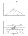
- FIG. 1 is a diagram explaining ADB control according to a comparative technique.
- the comparative technique uses a camera as an optical sensor.
- FIG. 1 shows an example of a camera image IMG and a corresponding light distribution pattern PTN.
- the ADB controller detects the object OBJ in the camera image IMG and determines the position (H, V) of the shaded portion (or dimmed portion) according to its position (x, y).
- the light distribution pattern PTN thus generated includes the light shielding portion SHD at the position (H, V) corresponding to the object OBJ, and can prevent glare.
- the position (H, V) of the light blocking portion SHD also moves following the object OBJ.
- FIG. 2 is a diagram explaining ADB control according to the comparative technique.
- the upper part of FIG. 2 shows the vertical coordinate y of the object OBJ included in the camera image IMG.
- the coordinate y is updated at the frame rate of the camera.
- the frame rate is 30 fps to 60 fps, 120 fps at the fastest, but signal processing for object detection may have a delay of several frames, that is, on the order of several tens of ms. Therefore, in object detection based on camera images, it is difficult to follow fast (for example, 1 Hz to several Hz) positional changes of the object without delay. Therefore, in the comparative technique, it is assumed that the vertical position y of the object OBJ in the camera image IMG does not change on a time scale shorter than 500 ms to 1 s. It generated the vertical position V of the SHD.
- the posture of the vehicle body is kept constant.
- An object in a camera image taken by a vehicle camera that does not change its posture moves relatively fast in the horizontal direction (horizontal direction) in the camera image, but moves slowly in the vertical direction (vertical direction). Tend. Therefore, the coordinate y changes slowly compared to the frame rate.
- the vertical position V of the light shielding portion SHD becomes constant without being affected by the pitching vibration of the vehicle body. Then, following the pitching vibration of the vehicle body, the light shielding portion SHD of the high beam light distribution pattern PTN vibrates up and down.
- FIGS. 3(a) to 3(c) are diagrams for explaining light distribution patterns generated by ADB control according to the comparative technique.
- FIGS. 3A to 3C show light distribution patterns PTN in normal operation, nose-up operation, and nose-down operation (nose dive). Even if pitching vibration occurs, it is not allowed to give glare to the object OBJ. Therefore, in the comparative technique, assuming pitching vibration, it is necessary to set the vertical length (height) ⁇ H of the light shielding portion SHD long by adding a margin to the height of the object OBJ. Even non-existent parts were shaded.
- the light-shielding portion SHD vibrates up and down, causing annoyance to the driver.
- the present disclosure has been made, and one of its exemplary purposes is to provide a lighting system capable of providing an improved field of view to the driver while preventing glare.
- a lighting system includes a variable light distribution lamp that includes a plurality of individually controllable pixels and emits lamp light having a light distribution pattern including a light blocking portion according to the state of the plurality of pixels; a sensor capable of detecting a dynamic component of the pitch angle during running; an optical sensor; of the pixels corresponding to the light-shielded portion are turned off, and the position of the off-pixel group corresponding to the light-shielded portion is set based on the target position of the light-shielded portion according to the dynamic component of the pitch angle of the vehicle body. and a second controller that moves up and down.
- Another aspect of the present disclosure relates to a control method for a variable light distribution lamp that includes a plurality of individually controllable pixels and emits lamp light having a light distribution pattern that includes a light blocking portion according to the state of the plurality of pixels.
- the control method includes the steps of detecting a dynamic component of the pitch angle of the vehicle during travel, detecting an object positioned in front of the vehicle, and generating a target position of the shaded portion based on the position of the object.
- the pixel group corresponding to the light-shielded portion is turned off, and the position of the off-pixel group corresponding to the light-shielded portion is changed based on the target position of the light-shielded portion, based on the dynamic pitch angle of the vehicle body. and moving up and down according to the component.
- FIGS. 3A to 3C are diagrams for explaining light distribution patterns generated by ADB control according to the comparative technique.
- 1 is a block diagram of a lighting system according to an embodiment
- FIGS. 5A and 5B are diagrams for explaining the pitch angle ⁇ p of the vehicle body.
- It is a functional block diagram of a second controller.
- 8 is a diagram showing waveforms of a dynamic pitch angle ⁇ d and a correction amount ⁇ V corresponding to the driving scene of FIG. 7;
- FIGS. 11A to 11C are diagrams for explaining light distribution patterns generated by ADB control according to the embodiment.
- FIG. 8 is a diagram showing light rays corresponding to the boundary between the light shielding portion SHD of the headlamp light and the irradiated portion (that is, the lower end or upper end of the light shielding portion) in the driving scene of FIG. 7 ;
- FIGS. 11A to 11C are diagrams showing examples of the relationship (control characteristics) between the dynamic pitch angle ⁇ d and the correction amount ⁇ V.
- FIG. 10 is a diagram showing a light distribution pattern PTN including a dimming portion;
- a lighting system includes a variable light distribution lamp that includes a plurality of individually controllable pixels and emits light having a light distribution pattern that includes a light blocking portion according to the state of the plurality of pixels; a sensor capable of detecting a dynamic component of the pitch angle during running; an optical sensor; Among the pixels, the pixel group corresponding to the light-shielded portion is turned off, and the position of the off-pixel group corresponding to the light-shielded portion is set based on the target position of the light-shielded portion according to the dynamic component of the pitch angle of the vehicle body. and a second controller for moving up and down.
- the light shielding portion when the rear of the vehicle body sinks (nose up), the light shielding portion is moved downward, and when the front of the vehicle body sinks (nose dive), the light shielding portion moves upward. You can prevent glare by moving.
- the light shielding portion when the vehicle body pitches, the light shielding portion is maintained at the same height with respect to the road surface, so that the sense of discomfort given to the driver can be reduced.
- “light shielding” and “pixels are off” are not limited to cases where the illuminance and brightness are completely zero, and include illuminance and brightness to the extent that glare is not given.
- the second controller may vertically move the ON pixel group corresponding to the illuminated portion surrounding the light shielding portion in conjunction with the OFF pixel group. That is, the entire light distribution formed by the variable light distribution lamp may be moved in the vertical direction.
- the second controller generates dimming information including the target position of the dimming portion based on the output of the optical sensor, and the second controller controls pixels corresponding to the dimming portion among the plurality of pixels.
- the brightness of the group is reduced compared to the ON pixel group, and the position of the pixel group corresponding to the dimmed portion is moved up and down based on the target position of the dimmed portion according to the dynamic component of the pitch angle of the vehicle body. You can move it in any direction.
- the target position of the shaded portion may change at frequencies lower than 5 Hz, and the dynamic component of the pitch angle may include frequencies higher than 0.5 Hz.
- the senor may include a gyro sensor.
- a dynamic pitch angle can be obtained by obtaining an angular velocity in the pitch direction with a gyro sensor and integrating it.
- a state in which member A is connected to member B refers to a case in which member A and member B are physically directly connected, and that member A and member B are electrically connected to each other. It also includes the case of being indirectly connected through other members that do not substantially affect the physical connection state or impair the functions and effects achieved by their combination.
- the state in which member C is provided between member A and member B refers to the case where member A and member C or member B and member C are directly connected, as well as the case where they are electrically connected. It also includes the case of being indirectly connected through other members that do not substantially affect the physical connection state or impair the functions and effects achieved by their combination.
- FIG. 4 is a block diagram of the lamp system 100 according to the embodiment.
- the lighting system 100 is a headlamp that is mounted on a vehicle and illuminates a field of view in front of the vehicle with a beam, and has an ADB (Adaptive Driving Beam) function.
- ADB Adaptive Driving Beam
- the lamp system 100 includes a high-definition lamp unit 110, a sensor 120, an optical sensor 150, a first controller 160 and a second controller 200.
- the high-definition lamp unit 110 is a variable light distribution lamp configured to irradiate part or all of the high beam area, and is also called an ADB lamp.
- the high-definition lamp unit 110 may cover part/all of the low beam area in addition to part/all of the high beam area.
- the high-definition lamp unit 110 includes a plurality of individually controllable pixels PIX, and emits lamp light having a light distribution pattern according to the states of the plurality of pixels PIX.
- high-definition lamp unit 110 includes light-emitting element array 112 and illumination optical system 114 .
- An LED array can be used as the light emitting element array 112 .
- the brightness of each pixel PIX may be controllable with two gradations of ON and OFF, or may be controllable with multiple gradations.
- PWM dimming can be used to achieve multiple gradations. may be expressed.
- the irradiation optical system 114 projects the output light of the light emitting element array 112 forward of the vehicle.
- the irradiation optical system 114 may be a lens optical system, a reflective optical system, or a combination thereof.
- a virtual vertical screen 2 is shown in FIG. It is assumed that the virtual vertical screen 2 is a coordinate system based on the road surface. The distance between the virtual vertical screen 2 and the vehicle (lamp) can be 10m or 25m.
- a high-beam light distribution pattern PTN is formed on the virtual vertical screen 2 by the light from the high-definition lamp unit 110 .
- the light distribution pattern PTN is the intensity distribution of lamp light on the virtual vertical screen 2 and is based on the on/off pattern of the plurality of pixels PIX of the light emitting element array 112 .
- the correspondence between the position of a certain pixel PIX and the illuminated portion on the virtual vertical screen 2 corresponding to that pixel PIX is determined by the illumination optical system 114, and is a mirror image relationship (horizontal inversion), vertical inversion, or vertical inversion. It may be reversed left and right.
- the optical sensor 150 senses the field of view in front of the vehicle.
- the optical sensor 150 can use an optical camera, but other optical sensors such as a LiDAR or ToF camera, a gating camera, or a stereo camera may also be used.
- the first controller 160 determines the position and type of the object OBJ present in front of the vehicle.
- the frame rate of the optical sensor 150 is approximately 30 to 120 fps, and object OBJ detection processing is executed for each frame. Signal processing for object detection may take longer than tens of ms. If the object OBJ should not give glare, for example, an oncoming vehicle or a preceding vehicle, the shading information INFO_SHD including the target position of the shading portion SHD of the light distribution pattern is generated.
- the vertical target position of the shaded portion SHD is generated by filtering the coordinate y of the object OBJ in the image data IMG.
- the position of the shaded portion SHD changes at a rate of 5 Hz or slower.
- the positional information of the shaded portion SHD may indicate the center coordinates of the shaded portion SHD.
- the light shielding portion SHD is rectangular, the coordinates of two diagonal vertices of the light shielding portion SHD may be indicated.
- the vehicle's front-rear tilt angle (vehicle posture) changes according to the front-rear weight balance.
- the inclination angle also changes depending on the unevenness and steps of the road surface while the vehicle is running.
- the tilt angle in the longitudinal direction corresponds to the rotation of the vehicle body about the horizontal axis extending in the left-right direction, and is referred to as the pitch angle (also referred to as the attitude angle) ⁇ p.
- the sensor 120 is provided so as to be able to detect a dynamic component of the pitch angle ⁇ p during running of the vehicle body on which the lighting system 100 is mounted.
- the second controller 200 receives shading information INFO_SHD from the first controller 160 .
- the second controller 200 turns off the pixel group corresponding to the light shielding portion SHD among the plurality of pixels PIX of the light emitting element array 112, and turns on the pixel group corresponding to the irradiated portion other than the light shielding portion in the light distribution pattern of the high beam.
- the second controller 200 detects the dynamic component of the pitch angle ⁇ p of the vehicle body according to the output (detection signal) S1 of the sensor 120.
- the second controller 200 vertically moves the position of the OFF pixel group corresponding to the shaded portion SHD based on the target position obtained from the shaded information INFO_SHD according to the dynamic component of the pitch angle ⁇ p of the vehicle body.
- the high-definition lamp unit 110 and the second controller 200 may be built in the headlamp 510.
- the senor 120 may be provided on the headlamp side or the vehicle side.
- the headlamp side it may be built in the housing (lamp body) of the headlamp, or may be externally attached to the lamp body.
- the vehicle side it may be arranged inside the passenger compartment or outside the passenger compartment, for example, inside the engine room.
- the optical sensor 150 may be provided on the vehicle side, or may be incorporated in the headlamp 510 . If the optical sensor 150 is built into the headlamp, the first controller 160 can also be built into the headlamp 510 . In this case, the first controller 160 and the second controller 200 may be configured with the same hardware.
- the first controller 160 may be provided on the vehicle side.
- the second controller 200 corrects the position of the light shielding portion SHD according to variations in the pitch angle ⁇ p caused by various factors while the vehicle is stationary and running.
- FIGS. 5(a) and 5(b) are diagrams for explaining the pitch angle ⁇ p of the vehicle body.
- FIG. 5(a) shows the pitch angle ⁇ p when the vehicle is stopped.
- the pitch angle ⁇ p when the vehicle is stationary is defined as a static pitch angle ⁇ s. Since the static pitch angle ⁇ s indicates the attitude of the vehicle when the vehicle is stopped, it is also referred to as the stationary vehicle attitude angle.
- the static pitch angle ⁇ s is determined according to the number of passengers, the riding position, the weight of luggage in the luggage compartment, the hardness of the front and rear suspensions, and the like.
- the angle formed by the straight line 12 parallel to the road surface 10 and the reference line 22 of the vehicle body 20 is taken as the pitch angle ⁇ p, and the upward direction of the reference line 22 (nose-up direction) is taken as positive. It is assumed that
- FIG. 5(b) shows the pitch angle ⁇ p while the vehicle is running.
- the pitch angle ⁇ p while the vehicle is running can be grasped as the sum of the static pitch angle ⁇ s and the dynamic component (also referred to as the dynamic pitch angle or pitch angle fluctuation amount) ⁇ d.
- the dynamic pitch angle ⁇ d can include the following components. ⁇ (i) Nose up due to vehicle acceleration, nose down due to deceleration ⁇ (ii) Changes in vehicle weight (weight balance) caused by road surface inclination ⁇ (iii) Fast vehicle vibration caused by uneven road surface
- vibrations of the vehicle body caused by unevenness of the road surface are generally within the range of 0.5 to 5 Hz, although they depend on the hardness of the suspension and the weight of the vehicle.
- a sharp vehicle body vibration is 0.9 to 2 Hz.
- the frequency component of pitch angle fluctuation exceeding 0.5 Hz (approximately 0.5 to 5 Hz, for example 1 to 2 Hz), which was conventionally removed as noise, is not removed as noise, but is corrected.
- the positional correction of the shaded portion for correcting the pitch angle variation during running is referred to as dynamic leveling.
- the sensor 120 is provided so as to detect the dynamic component ⁇ d of the pitch angle ⁇ p while the vehicle body is running.
- the senor 120 includes a gyro sensor.
- the gyro sensor may be attached in any direction, but is preferably installed so that one of its detection axes faces the left-right horizontal direction of the vehicle body, and generates a detection signal S1 indicating the angular velocity ⁇ p of rotational motion around this detection axis.
- the gyro sensor may be triaxial or uniaxial.
- the second controller 200 is an ECU (Electronic Control Unit) that integrates functions related to optical axis correction, and performs processing related to dynamic leveling.
- the second controller 200 may be an ECU dedicated to leveling (also referred to as a leveling ECU), an ECU integrated with a controller having other functions, or divided into a plurality of ECUs. may
- the functions of the second controller 200 may be realized by software processing, hardware processing, or a combination of software processing and hardware processing. Specifically, software processing is implemented by combining processors (hardware) such as CPU (Central Processing Unit), MPU (Micro Processing Unit), and microcontrollers, and software programs executed by the processor (hardware). .
- the second controller 200 may be a combination of multiple processors (microcontrollers).
- hardware processing is implemented by hardware such as ASIC (Application Specific Integrated Circuit), controller IC, and FPGA (Field Programmable Gate Array).
- ASIC Application Specific Integrated Circuit
- controller IC controller IC
- FPGA Field Programmable Gate Array
- the second controller 200 detects the dynamic component ⁇ d of the pitch angle ⁇ p while the vehicle is running by integrating the angular velocity ⁇ p indicated by the detection signal S1.
- the dynamic component ⁇ d here can be regarded as a component included in a predetermined frequency band higher than 0.5 Hz among variations in the pitch angle ⁇ p.
- components included in a predetermined frequency band are subject to correction as dynamic components.
- the predetermined frequency band can be set, for example, within a range of approximately 0.5 Hz to 5 Hz. Which frequency band is to be corrected may be determined based on the stiffness of the suspension, the mass of the vehicle body, and the like.
- the second controller 200 sets the position (position in the vertical direction V) of the light shielding portion SHD of the light distribution pattern PTN to the target indicated by the light shielding information INFO_SHD according to the dynamic component ⁇ d of the pitch angle ⁇ p of the running vehicle body. It is moved upward and/or downward with reference to the position V0 .
- the second controller 200 moves the light shielding portion SHD downward in response to the positive dynamic pitch angle ⁇ d. Conversely, the second controller 200 moves the light blocking portion SHD upward in response to the negative dynamic pitch angle ⁇ d.
- the second controller 200 moves the position of the light shielding portion SHD upward and downward with respect to the predetermined position V0 so as to cancel the dynamic component ⁇ d of the pitch angle ⁇ p.
- the predetermined position V0 is the vertical coordinate at which the light shielding portion SHD should be located when the variation of the pitch angle ⁇ p is zero.
- the second controller 200 changes the positions of the OFF pixel groups of the plurality of pixels PIX of the light emitting element array 112 in order to move the light shielding portion SHD of the light distribution pattern PTN on the virtual vertical screen 2 up and down. How many pixels the OFF pixel group is to be shifted with respect to a certain fluctuation range of the pitch angle ⁇ p can be determined geometrically. Let ⁇ y be the pixel shift amount.
- FIG. 6 is a functional block diagram of the second controller 200.
- the second controller 200 includes a pitch angle calculator 210 and a light blocking position corrector 220 .
- the pitch angle calculator 210 detects the dynamic component ⁇ d of the pitch angle ⁇ p based on the output of the sensor 120 .
- the pitch angle calculator 210 integrates the angular velocity ⁇ p indicated by the detection signal S1.
- the pitch angle calculation unit 210 calculates the dynamic pitch angle ⁇ d by performing calculation processing on the integrated value as necessary. This arithmetic processing can include filtering (band limiting processing), moving average processing, and the like.
- the light shielding position correction unit 220 raises and lowers the position of the light shielding portion SHD based on the dynamic pitch angle ⁇ d.
- the light shielding position corrector 220 includes a correction amount calculator 222 and a corrector 224 .
- the correction amount calculator 222 calculates the vertical movement amount (correction amount ⁇ V) of the light shielding portion SHD on the virtual vertical screen 2 based on the dynamic pitch angle ⁇ d.
- the positive correction amount ⁇ V corresponds to the upward shift of the shaded portion SHD
- the negative correction amount ⁇ V corresponds to the downward shift of the shaded portion SHD.
- the correction unit 224 controls the light emitting element array 112 so that the light shielding portion SHD moves by the correction amount ⁇ V.
- the light-emitting element array 112 has an interface for inputting image data that designates on/off (or luminance) of a plurality of pixels PIX.
- the correction unit 224 may shift the position of the OFF pixel group corresponding to the shaded portion SHD included in the image data up and down by the number of pixels ⁇ y corresponding to the correction amount ⁇ V. That is, the correction unit 224 moves the position of the OFF pixel group of the light distribution pattern included in the image data upward and downward with respect to the predetermined position y0 so as to cancel the dynamic component ⁇ d of the pitch angle ⁇ p.
- the predetermined position y0 is a reference position corresponding to V0 .
- the configuration of the lamp system 100 is as described above. Next, the operation will be explained.
- FIG. 7 is a diagram showing an example of a vehicle traveling scene.
- the vehicle 30 is traveling from left to right on the paper surface, and shows how it climbs over a step 14 on the road surface 10 .
- FIG. 7 shows attitudes of the vehicle 30 at a plurality of times t 0 to t 4 . Each time t 0 to t 4 indicates the following states.
- Time t0 The vehicle is running in front of the step 14
- Time t1 The front wheels have run over the step 14
- Time t2 The front wheels have run over the step 14
- Time t3 The rear wheels have run over the step 14
- State Time t 4 The state where the rear wheels have run over the step 14
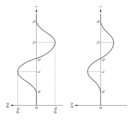
- the dynamic pitch angle ⁇ d is 0 at times t 0 , t 2 and t 4 .
- the dynamic pitch angle ⁇ d at time t1 takes a positive value ⁇ d1
- the dynamic pitch angle ⁇ d at time t3 takes a negative value ⁇ d3 .
- FIG. 8 is a diagram showing the waveform of the dynamic pitch angle ⁇ d and the waveform of the correction amount ⁇ V corresponding to the driving scene of FIG. As shown in FIG. 7, the dynamic pitch angle ⁇ d swings in the positive direction, then swings in the negative direction, and eventually returns to zero.
- a correction amount ⁇ V is generated corresponding to the variation of the dynamic pitch angle ⁇ d.
- FIGS. 9(a) to 9(c) are diagrams for explaining light distribution patterns generated by ADB control according to the embodiment.
- FIGS. 9A to 9C show the light distribution patterns PTN in the normal state, the nose-up state, and the nose-down state (nose dive).
- the vertical length (height) ⁇ H of the light shielding portion SHD does not require a margin considering the pitching vibration, and the height ⁇ H of the light shielding portion can be made smaller than in the comparison technique.
- the light shielding portion SHD vibrates up and down when the vehicle body pitches, which causes annoyance to the driver. Since it is suppressed, it is possible to suppress the annoyance and discomfort given to the driver.
- each light shielding portion SHD there may be a plurality of light shielding portions SHD, and when there are a plurality of light shielding portions SHD, the vertical position of each light shielding portion SHD is corrected following the variation of the pitch angle.
- FIG. 10 is a diagram showing light rays corresponding to the boundary between the light shielding portion SHD of the headlamp light and the irradiated portion (that is, the lower end or upper end of the light shielding portion) in the driving scene of FIG.
- the light ray 32 at the boundary of the lamp light shielding portion SHD can always be kept at a constant angle with respect to the road surface 10 .
- the lamp system 100 when the rear of the vehicle 30 sinks as shown at time t1 in FIG. 10, glare can be prevented by lowering the light blocking portion SHD. Further, when the front of the vehicle 30 sinks as shown at time t3 in FIG. 10, the glare can be prevented by raising the light shielding portion SHD.
- the light shielding portion SHD on the virtual vertical screen in front of the vehicle is blocked.
- the position can be kept constant at all times, preventing objects in front of the vehicle from brightening or darkening, thus providing an improved field of vision.
- the static pitch angle ⁇ s can be regarded as a reference value of the pitch angle ⁇ p
- the dynamic pitch angle ⁇ d can be regarded as a dynamic deviation from the reference value of the pitch angle ⁇ p. Therefore, the second controller 200 controls the high-definition lamp unit 110 according to the deviation ⁇ d so that the angle formed by the light beam 32 corresponding to the light shielding portion SHD and the road surface 10 is constant. .
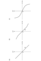
- FIGS. 11(a) to 11(c) are diagrams showing examples of the relationship (control characteristics) between the dynamic pitch angle ⁇ d and the correction amount ⁇ V.
- the correction amount ⁇ V is expressed as a linear expression having a proportionality constant (referred to as a reference gain g 0 ) based on the distance L with respect to the dynamic pitch angle ⁇ d. can be determined.
- a reference gain g 0 a proportionality constant
- the illumination optical system 114 is a complex optical system including a reflector having a hyperbolic paraboloid, an elliptical paraboloid, a paraboloid of revolution, and a free paraboloid
- the correction amount ⁇ V may be defined by a polygonal line with respect to the dynamic pitch angle ⁇ d.
- a control characteristic such as (b) may be defined. In this case, it is possible to suppress glare when a control delay occurs in a situation where the nose-up posture is assumed immediately after the nose dive.
- the illumination optical system 114 is a complex optical system that includes a reflecting mirror with an elliptical paraboloid or a free paraboloid, as shown in FIG. may
- the movement of the light shielding portion SHD may be disabled.
- the dynamic pitch angle ⁇ d includes a frequency component that exceeds the response speed of the second controller 200, glare can be suppressed by invalidating the movement of the light blocking portion SHD.
- the pitch angle control may be fixed to the pitch angle control acquired while the vehicle is stopped or in a stable running state. Also, when returning, it is better not to return it immediately, but gradually return it over a period of several seconds. In the case of the high-definition lamp unit 110 capable of controlling the intensity distribution with multiple gradations, it is preferable to apply blurring or gradation to restore the intensity gradually.
- the gyro sensor detects the dynamic component of the pitch angle in the embodiments, the present disclosure is not limited thereto.
- the dynamic component of the pitch angle may be detected based on a combination of a front vehicle height sensor provided on the front suspension of the vehicle body and a rear vehicle height sensor provided on the rear suspension of the vehicle body.
- high definition lamp unit 110 may include a light source that produces light having a substantially flat intensity distribution and a spatial light modulator that spatially patterns the light emitted by the light source.
- Spatial light modulators are exemplified by DMDs (Digital Micromirror Devices) and liquid crystal devices.
- the irradiated portion of the high beam light distribution pattern PTN is fixed and only the light shielding portion SHD is vertically moved, but this is not the only option.
- the second controller 200 vertically moves the ON pixel group corresponding to the illuminated portion surrounding the light shielding portion SHD in conjunction with the OFF pixel group corresponding to the light shielding portion SHD. That is, the entire image data of the light distribution pattern PTN is vertically shifted according to the pitch angle ⁇ p.
- Modification 4 In the embodiment, the generation and correction of the high beam light distribution pattern PTN including the light blocking portion SHD has been described, but the present disclosure can also be applied to a light distribution pattern including a dimming portion.
- FIG. 12 is a diagram showing a light distribution pattern PTN including a dimming portion.
- FIG. 12 shows an example of a camera image IMG and a corresponding light distribution pattern PTN.
- the ADB controller detects objects OBJ 1 -OBJ 3 in the camera image IMG.
- Objects OBJ 1 and OBJ 2 are highly reflective signs, and object OBJ 3 is a pedestrian's head, which are defined as objects to be dimmed.
- the light distribution pattern PTN thus generated includes dimmed portions DIM 1 -DIM 3 at positions corresponding to the objects OBJ 1 -OBJ 3 .
- the objects OBJ 1 and OBJ 2 such as signs with high reflectance the target of the dimming portion DIM, it is possible to suppress glare caused by the reflected light to the driver.
- the object OBJ3 corresponding to the head of a pedestrian or a bicycle driver (referred to as a pedestrian or the like) as the target of the dimming portion DIM, it is possible to prevent the pedestrian or the like from being glared.
- the second controller 200 moves the height-direction positions V 1 to V 3 of the dimming portions DIM 1 to DIM 3 up and down, following the variation of the vehicle body, that is, the variation of the pitch angle. As a result, the vertical relative positional relationship between the objects OBJ 1 to OBJ 3 and the corresponding dimming portions DIM 1 to DIM 3 remains unchanged.
- the method by which the second controller 200 vertically shifts the position of the light shielding portion SHD is not limited to correcting the image data supplied to the light emitting element array 112 .
- the light emitting element array 112 may have a pixel shift function.
- the light-emitting element array 112 may be provided with reference image data and a pixel shift amount ⁇ y.
- the present disclosure relates to vehicle lamps.
- SYMBOLS 100... Lamp system, 110... High definition lamp unit, 112... Light emitting element array, 114... Irradiation optical system, PIX... Pixel, 120... Sensor, 150... Optical sensor, 160... First controller, 200... Second controller, 210 Pitch angle calculation unit 220 Shielding position correction unit 222 Correction amount calculation unit 224 Correction unit 2 Virtual vertical screen.
Landscapes
- Engineering & Computer Science (AREA)
- General Engineering & Computer Science (AREA)
- Physics & Mathematics (AREA)
- Spectroscopy & Molecular Physics (AREA)
- Microelectronics & Electronic Packaging (AREA)
- Optics & Photonics (AREA)
- Mechanical Engineering (AREA)
- Mathematical Physics (AREA)
- Lighting Device Outwards From Vehicle And Optical Signal (AREA)
Priority Applications (1)
| Application Number | Priority Date | Filing Date | Title |
|---|---|---|---|
| JP2023562354A JPWO2023090331A1 (https=) | 2021-11-19 | 2022-11-15 |
Applications Claiming Priority (2)
| Application Number | Priority Date | Filing Date | Title |
|---|---|---|---|
| JP2021-188628 | 2021-11-19 | ||
| JP2021188628 | 2021-11-19 |
Publications (1)
| Publication Number | Publication Date |
|---|---|
| WO2023090331A1 true WO2023090331A1 (ja) | 2023-05-25 |
Family
ID=86397100
Family Applications (1)
| Application Number | Title | Priority Date | Filing Date |
|---|---|---|---|
| PCT/JP2022/042450 Ceased WO2023090331A1 (ja) | 2021-11-19 | 2022-11-15 | 灯具システムおよびランプの制御方法 |
Country Status (2)
| Country | Link |
|---|---|
| JP (1) | JPWO2023090331A1 (https=) |
| WO (1) | WO2023090331A1 (https=) |
Cited By (1)
| Publication number | Priority date | Publication date | Assignee | Title |
|---|---|---|---|---|
| WO2025159052A1 (ja) * | 2024-01-24 | 2025-07-31 | 株式会社小糸製作所 | 配光可変ランプの制御装置、車両用灯具、ソフトウェアプログラム |
Citations (2)
| Publication number | Priority date | Publication date | Assignee | Title |
|---|---|---|---|---|
| JP2004071409A (ja) * | 2002-08-07 | 2004-03-04 | Denso Corp | 車両用灯具および車両用灯具の配光制御方法 |
| JP2019038279A (ja) * | 2017-08-22 | 2019-03-14 | スタンレー電気株式会社 | 車両用灯具の制御装置、車両用灯具システム |
-
2022
- 2022-11-15 JP JP2023562354A patent/JPWO2023090331A1/ja active Pending
- 2022-11-15 WO PCT/JP2022/042450 patent/WO2023090331A1/ja not_active Ceased
Patent Citations (2)
| Publication number | Priority date | Publication date | Assignee | Title |
|---|---|---|---|---|
| JP2004071409A (ja) * | 2002-08-07 | 2004-03-04 | Denso Corp | 車両用灯具および車両用灯具の配光制御方法 |
| JP2019038279A (ja) * | 2017-08-22 | 2019-03-14 | スタンレー電気株式会社 | 車両用灯具の制御装置、車両用灯具システム |
Cited By (1)
| Publication number | Priority date | Publication date | Assignee | Title |
|---|---|---|---|---|
| WO2025159052A1 (ja) * | 2024-01-24 | 2025-07-31 | 株式会社小糸製作所 | 配光可変ランプの制御装置、車両用灯具、ソフトウェアプログラム |
Also Published As
| Publication number | Publication date |
|---|---|
| JPWO2023090331A1 (https=) | 2023-05-25 |
Similar Documents
| Publication | Publication Date | Title |
|---|---|---|
| US10369922B2 (en) | Vehicle headlight device | |
| US20200369200A1 (en) | Vehicle detecting device and vehicle lamp system | |
| CN110709281B (zh) | 车辆用灯具及其控制装置、控制方法 | |
| US12503038B2 (en) | Lamp system | |
| WO2023090331A1 (ja) | 灯具システムおよびランプの制御方法 | |
| US12358417B2 (en) | Lamp system | |
| US20240302018A1 (en) | Lamp system | |
| CN120677087A (zh) | 车辆用灯具系统、配光可变灯的控制器、控制方法、程序 | |
| US20250326350A1 (en) | Vehicle lamp apparatus | |
| JP2025179887A (ja) | 制御装置、車両用灯具システム、およびソフトウェアプログラム | |
| US20250297719A1 (en) | Vehicle lamp | |
| WO2023090328A1 (ja) | 灯具システム | |
| EP4635797A1 (en) | Vehicle lamp and vehicle lamp system | |
| WO2024195545A1 (ja) | 灯具システムおよびランプのコントローラおよび制御方法 | |
| WO2025079504A1 (ja) | 車両用灯具、配光可変ランプの制御装置、ソフトウェアプログラム | |
| CN118284541A (zh) | 灯具系统 | |
| CN121986038A (en) | Vehicle lamp, control device for variable light distribution, and software program | |
| JP7152511B2 (ja) | 光学素子、それを用いた車両用前照灯ユニット、及び、車両用前照灯装置 | |
| WO2024203680A1 (ja) | 配光可変ランプの制御装置、車両用灯具、ソフトウェアプログラム | |
| WO2025159052A1 (ja) | 配光可変ランプの制御装置、車両用灯具、ソフトウェアプログラム |
Legal Events
| Date | Code | Title | Description |
|---|---|---|---|
| 121 | Ep: the epo has been informed by wipo that ep was designated in this application |
Ref document number: 22895612 Country of ref document: EP Kind code of ref document: A1 |
|
| ENP | Entry into the national phase |
Ref document number: 2023562354 Country of ref document: JP Kind code of ref document: A |
|
| NENP | Non-entry into the national phase |
Ref country code: DE |
|
| 122 | Ep: pct application non-entry in european phase |
Ref document number: 22895612 Country of ref document: EP Kind code of ref document: A1 |