WO2023090328A1 - 灯具システム - Google Patents
灯具システム Download PDFInfo
- Publication number
- WO2023090328A1 WO2023090328A1 PCT/JP2022/042446 JP2022042446W WO2023090328A1 WO 2023090328 A1 WO2023090328 A1 WO 2023090328A1 JP 2022042446 W JP2022042446 W JP 2022042446W WO 2023090328 A1 WO2023090328 A1 WO 2023090328A1
- Authority
- WO
- WIPO (PCT)
- Prior art keywords
- pitch angle
- leveling
- vehicle
- sensor
- lamp
- Prior art date
- Legal status (The legal status is an assumption and is not a legal conclusion. Google has not performed a legal analysis and makes no representation as to the accuracy of the status listed.)
- Ceased
Links
Images

















Classifications
-
- B—PERFORMING OPERATIONS; TRANSPORTING
- B60—VEHICLES IN GENERAL
- B60Q—ARRANGEMENT OF SIGNALLING OR LIGHTING DEVICES, THE MOUNTING OR SUPPORTING THEREOF OR CIRCUITS THEREFOR, FOR VEHICLES IN GENERAL
- B60Q1/00—Arrangement of optical signalling or lighting devices, the mounting or supporting thereof or circuits therefor
- B60Q1/02—Arrangement of optical signalling or lighting devices, the mounting or supporting thereof or circuits therefor the devices being primarily intended to illuminate the way ahead or to illuminate other areas of way or environments
- B60Q1/04—Arrangement of optical signalling or lighting devices, the mounting or supporting thereof or circuits therefor the devices being primarily intended to illuminate the way ahead or to illuminate other areas of way or environments the devices being headlights
- B60Q1/06—Arrangement of optical signalling or lighting devices, the mounting or supporting thereof or circuits therefor the devices being primarily intended to illuminate the way ahead or to illuminate other areas of way or environments the devices being headlights adjustable, e.g. remotely-controlled from inside vehicle
- B60Q1/08—Arrangement of optical signalling or lighting devices, the mounting or supporting thereof or circuits therefor the devices being primarily intended to illuminate the way ahead or to illuminate other areas of way or environments the devices being headlights adjustable, e.g. remotely-controlled from inside vehicle automatically
- B60Q1/10—Arrangement of optical signalling or lighting devices, the mounting or supporting thereof or circuits therefor the devices being primarily intended to illuminate the way ahead or to illuminate other areas of way or environments the devices being headlights adjustable, e.g. remotely-controlled from inside vehicle automatically due to vehicle inclination, e.g. due to load distribution
- B60Q1/11—Arrangement of optical signalling or lighting devices, the mounting or supporting thereof or circuits therefor the devices being primarily intended to illuminate the way ahead or to illuminate other areas of way or environments the devices being headlights adjustable, e.g. remotely-controlled from inside vehicle automatically due to vehicle inclination, e.g. due to load distribution by mechanical means
-
- B—PERFORMING OPERATIONS; TRANSPORTING
- B60—VEHICLES IN GENERAL
- B60Q—ARRANGEMENT OF SIGNALLING OR LIGHTING DEVICES, THE MOUNTING OR SUPPORTING THEREOF OR CIRCUITS THEREFOR, FOR VEHICLES IN GENERAL
- B60Q1/00—Arrangement of optical signalling or lighting devices, the mounting or supporting thereof or circuits therefor
- B60Q1/0017—Devices integrating an element dedicated to another function
- B60Q1/0023—Devices integrating an element dedicated to another function the element being a sensor, e.g. distance sensor, camera
-
- B—PERFORMING OPERATIONS; TRANSPORTING
- B60—VEHICLES IN GENERAL
- B60Q—ARRANGEMENT OF SIGNALLING OR LIGHTING DEVICES, THE MOUNTING OR SUPPORTING THEREOF OR CIRCUITS THEREFOR, FOR VEHICLES IN GENERAL
- B60Q1/00—Arrangement of optical signalling or lighting devices, the mounting or supporting thereof or circuits therefor
- B60Q1/02—Arrangement of optical signalling or lighting devices, the mounting or supporting thereof or circuits therefor the devices being primarily intended to illuminate the way ahead or to illuminate other areas of way or environments
- B60Q1/04—Arrangement of optical signalling or lighting devices, the mounting or supporting thereof or circuits therefor the devices being primarily intended to illuminate the way ahead or to illuminate other areas of way or environments the devices being headlights
- B60Q1/06—Arrangement of optical signalling or lighting devices, the mounting or supporting thereof or circuits therefor the devices being primarily intended to illuminate the way ahead or to illuminate other areas of way or environments the devices being headlights adjustable, e.g. remotely-controlled from inside vehicle
- B60Q1/08—Arrangement of optical signalling or lighting devices, the mounting or supporting thereof or circuits therefor the devices being primarily intended to illuminate the way ahead or to illuminate other areas of way or environments the devices being headlights adjustable, e.g. remotely-controlled from inside vehicle automatically
- B60Q1/085—Arrangement of optical signalling or lighting devices, the mounting or supporting thereof or circuits therefor the devices being primarily intended to illuminate the way ahead or to illuminate other areas of way or environments the devices being headlights adjustable, e.g. remotely-controlled from inside vehicle automatically due to special conditions, e.g. adverse weather, type of road, badly illuminated road signs or potential dangers
-
- B—PERFORMING OPERATIONS; TRANSPORTING
- B60—VEHICLES IN GENERAL
- B60Q—ARRANGEMENT OF SIGNALLING OR LIGHTING DEVICES, THE MOUNTING OR SUPPORTING THEREOF OR CIRCUITS THEREFOR, FOR VEHICLES IN GENERAL
- B60Q1/00—Arrangement of optical signalling or lighting devices, the mounting or supporting thereof or circuits therefor
- B60Q1/02—Arrangement of optical signalling or lighting devices, the mounting or supporting thereof or circuits therefor the devices being primarily intended to illuminate the way ahead or to illuminate other areas of way or environments
- B60Q1/04—Arrangement of optical signalling or lighting devices, the mounting or supporting thereof or circuits therefor the devices being primarily intended to illuminate the way ahead or to illuminate other areas of way or environments the devices being headlights
- B60Q1/06—Arrangement of optical signalling or lighting devices, the mounting or supporting thereof or circuits therefor the devices being primarily intended to illuminate the way ahead or to illuminate other areas of way or environments the devices being headlights adjustable, e.g. remotely-controlled from inside vehicle
- B60Q1/08—Arrangement of optical signalling or lighting devices, the mounting or supporting thereof or circuits therefor the devices being primarily intended to illuminate the way ahead or to illuminate other areas of way or environments the devices being headlights adjustable, e.g. remotely-controlled from inside vehicle automatically
- B60Q1/10—Arrangement of optical signalling or lighting devices, the mounting or supporting thereof or circuits therefor the devices being primarily intended to illuminate the way ahead or to illuminate other areas of way or environments the devices being headlights adjustable, e.g. remotely-controlled from inside vehicle automatically due to vehicle inclination, e.g. due to load distribution
-
- B—PERFORMING OPERATIONS; TRANSPORTING
- B60—VEHICLES IN GENERAL
- B60Q—ARRANGEMENT OF SIGNALLING OR LIGHTING DEVICES, THE MOUNTING OR SUPPORTING THEREOF OR CIRCUITS THEREFOR, FOR VEHICLES IN GENERAL
- B60Q1/00—Arrangement of optical signalling or lighting devices, the mounting or supporting thereof or circuits therefor
- B60Q1/02—Arrangement of optical signalling or lighting devices, the mounting or supporting thereof or circuits therefor the devices being primarily intended to illuminate the way ahead or to illuminate other areas of way or environments
- B60Q1/04—Arrangement of optical signalling or lighting devices, the mounting or supporting thereof or circuits therefor the devices being primarily intended to illuminate the way ahead or to illuminate other areas of way or environments the devices being headlights
- B60Q1/06—Arrangement of optical signalling or lighting devices, the mounting or supporting thereof or circuits therefor the devices being primarily intended to illuminate the way ahead or to illuminate other areas of way or environments the devices being headlights adjustable, e.g. remotely-controlled from inside vehicle
- B60Q1/08—Arrangement of optical signalling or lighting devices, the mounting or supporting thereof or circuits therefor the devices being primarily intended to illuminate the way ahead or to illuminate other areas of way or environments the devices being headlights adjustable, e.g. remotely-controlled from inside vehicle automatically
- B60Q1/10—Arrangement of optical signalling or lighting devices, the mounting or supporting thereof or circuits therefor the devices being primarily intended to illuminate the way ahead or to illuminate other areas of way or environments the devices being headlights adjustable, e.g. remotely-controlled from inside vehicle automatically due to vehicle inclination, e.g. due to load distribution
- B60Q1/115—Arrangement of optical signalling or lighting devices, the mounting or supporting thereof or circuits therefor the devices being primarily intended to illuminate the way ahead or to illuminate other areas of way or environments the devices being headlights adjustable, e.g. remotely-controlled from inside vehicle automatically due to vehicle inclination, e.g. due to load distribution by electric means
-
- F—MECHANICAL ENGINEERING; LIGHTING; HEATING; WEAPONS; BLASTING
- F21—LIGHTING
- F21S—NON-PORTABLE LIGHTING DEVICES; SYSTEMS THEREOF; VEHICLE LIGHTING DEVICES SPECIALLY ADAPTED FOR VEHICLE EXTERIORS
- F21S41/00—Illuminating devices specially adapted for vehicle exteriors, e.g. headlamps
- F21S41/10—Illuminating devices specially adapted for vehicle exteriors, e.g. headlamps characterised by the light source
- F21S41/14—Illuminating devices specially adapted for vehicle exteriors, e.g. headlamps characterised by the light source characterised by the type of light source
- F21S41/141—Light emitting diodes [LED]
- F21S41/143—Light emitting diodes [LED] the main emission direction of the LED being parallel to the optical axis of the illuminating device
-
- F—MECHANICAL ENGINEERING; LIGHTING; HEATING; WEAPONS; BLASTING
- F21—LIGHTING
- F21S—NON-PORTABLE LIGHTING DEVICES; SYSTEMS THEREOF; VEHICLE LIGHTING DEVICES SPECIALLY ADAPTED FOR VEHICLE EXTERIORS
- F21S41/00—Illuminating devices specially adapted for vehicle exteriors, e.g. headlamps
- F21S41/10—Illuminating devices specially adapted for vehicle exteriors, e.g. headlamps characterised by the light source
- F21S41/14—Illuminating devices specially adapted for vehicle exteriors, e.g. headlamps characterised by the light source characterised by the type of light source
- F21S41/141—Light emitting diodes [LED]
- F21S41/151—Light emitting diodes [LED] arranged in one or more lines
- F21S41/153—Light emitting diodes [LED] arranged in one or more lines arranged in a matrix
-
- F—MECHANICAL ENGINEERING; LIGHTING; HEATING; WEAPONS; BLASTING
- F21—LIGHTING
- F21S—NON-PORTABLE LIGHTING DEVICES; SYSTEMS THEREOF; VEHICLE LIGHTING DEVICES SPECIALLY ADAPTED FOR VEHICLE EXTERIORS
- F21S41/00—Illuminating devices specially adapted for vehicle exteriors, e.g. headlamps
- F21S41/60—Illuminating devices specially adapted for vehicle exteriors, e.g. headlamps characterised by a variable light distribution
- F21S41/65—Illuminating devices specially adapted for vehicle exteriors, e.g. headlamps characterised by a variable light distribution by acting on light sources
- F21S41/657—Illuminating devices specially adapted for vehicle exteriors, e.g. headlamps characterised by a variable light distribution by acting on light sources by moving light sources
-
- F—MECHANICAL ENGINEERING; LIGHTING; HEATING; WEAPONS; BLASTING
- F21—LIGHTING
- F21S—NON-PORTABLE LIGHTING DEVICES; SYSTEMS THEREOF; VEHICLE LIGHTING DEVICES SPECIALLY ADAPTED FOR VEHICLE EXTERIORS
- F21S41/00—Illuminating devices specially adapted for vehicle exteriors, e.g. headlamps
- F21S41/60—Illuminating devices specially adapted for vehicle exteriors, e.g. headlamps characterised by a variable light distribution
- F21S41/65—Illuminating devices specially adapted for vehicle exteriors, e.g. headlamps characterised by a variable light distribution by acting on light sources
- F21S41/663—Illuminating devices specially adapted for vehicle exteriors, e.g. headlamps characterised by a variable light distribution by acting on light sources by switching light sources
-
- F—MECHANICAL ENGINEERING; LIGHTING; HEATING; WEAPONS; BLASTING
- F21—LIGHTING
- F21V—FUNCTIONAL FEATURES OR DETAILS OF LIGHTING DEVICES OR SYSTEMS THEREOF; STRUCTURAL COMBINATIONS OF LIGHTING DEVICES WITH OTHER ARTICLES, NOT OTHERWISE PROVIDED FOR
- F21V14/00—Controlling the distribution of the light emitted by adjustment of elements
-
- F—MECHANICAL ENGINEERING; LIGHTING; HEATING; WEAPONS; BLASTING
- F21—LIGHTING
- F21V—FUNCTIONAL FEATURES OR DETAILS OF LIGHTING DEVICES OR SYSTEMS THEREOF; STRUCTURAL COMBINATIONS OF LIGHTING DEVICES WITH OTHER ARTICLES, NOT OTHERWISE PROVIDED FOR
- F21V14/00—Controlling the distribution of the light emitted by adjustment of elements
- F21V14/02—Controlling the distribution of the light emitted by adjustment of elements by movement of light sources
-
- F—MECHANICAL ENGINEERING; LIGHTING; HEATING; WEAPONS; BLASTING
- F21—LIGHTING
- F21V—FUNCTIONAL FEATURES OR DETAILS OF LIGHTING DEVICES OR SYSTEMS THEREOF; STRUCTURAL COMBINATIONS OF LIGHTING DEVICES WITH OTHER ARTICLES, NOT OTHERWISE PROVIDED FOR
- F21V14/00—Controlling the distribution of the light emitted by adjustment of elements
- F21V14/04—Controlling the distribution of the light emitted by adjustment of elements by movement of reflectors
-
- F—MECHANICAL ENGINEERING; LIGHTING; HEATING; WEAPONS; BLASTING
- F21—LIGHTING
- F21V—FUNCTIONAL FEATURES OR DETAILS OF LIGHTING DEVICES OR SYSTEMS THEREOF; STRUCTURAL COMBINATIONS OF LIGHTING DEVICES WITH OTHER ARTICLES, NOT OTHERWISE PROVIDED FOR
- F21V7/00—Reflectors for light sources
-
- F—MECHANICAL ENGINEERING; LIGHTING; HEATING; WEAPONS; BLASTING
- F21—LIGHTING
- F21V—FUNCTIONAL FEATURES OR DETAILS OF LIGHTING DEVICES OR SYSTEMS THEREOF; STRUCTURAL COMBINATIONS OF LIGHTING DEVICES WITH OTHER ARTICLES, NOT OTHERWISE PROVIDED FOR
- F21V9/00—Elements for modifying spectral properties, polarisation or intensity of the light emitted, e.g. filters
- F21V9/40—Elements for modifying spectral properties, polarisation or intensity of the light emitted, e.g. filters with provision for controlling spectral properties, e.g. colour, or intensity
-
- B—PERFORMING OPERATIONS; TRANSPORTING
- B60—VEHICLES IN GENERAL
- B60Q—ARRANGEMENT OF SIGNALLING OR LIGHTING DEVICES, THE MOUNTING OR SUPPORTING THEREOF OR CIRCUITS THEREFOR, FOR VEHICLES IN GENERAL
- B60Q2300/00—Indexing codes for automatically adjustable headlamps or automatically dimmable headlamps
- B60Q2300/05—Special features for controlling or switching of the light beam
- B60Q2300/054—Variable non-standard intensity, i.e. emission of various beam intensities different from standard intensities, e.g. continuous or stepped transitions of intensity
-
- B—PERFORMING OPERATIONS; TRANSPORTING
- B60—VEHICLES IN GENERAL
- B60Q—ARRANGEMENT OF SIGNALLING OR LIGHTING DEVICES, THE MOUNTING OR SUPPORTING THEREOF OR CIRCUITS THEREFOR, FOR VEHICLES IN GENERAL
- B60Q2300/00—Indexing codes for automatically adjustable headlamps or automatically dimmable headlamps
- B60Q2300/10—Indexing codes relating to particular vehicle conditions
- B60Q2300/11—Linear movements of the vehicle
- B60Q2300/114—Vehicle acceleration or deceleration
-
- B—PERFORMING OPERATIONS; TRANSPORTING
- B60—VEHICLES IN GENERAL
- B60Q—ARRANGEMENT OF SIGNALLING OR LIGHTING DEVICES, THE MOUNTING OR SUPPORTING THEREOF OR CIRCUITS THEREFOR, FOR VEHICLES IN GENERAL
- B60Q2300/00—Indexing codes for automatically adjustable headlamps or automatically dimmable headlamps
- B60Q2300/10—Indexing codes relating to particular vehicle conditions
- B60Q2300/13—Attitude of the vehicle body
- B60Q2300/132—Pitch
-
- F—MECHANICAL ENGINEERING; LIGHTING; HEATING; WEAPONS; BLASTING
- F21—LIGHTING
- F21W—INDEXING SCHEME ASSOCIATED WITH SUBCLASSES F21K, F21L, F21S and F21V, RELATING TO USES OR APPLICATIONS OF LIGHTING DEVICES OR SYSTEMS
- F21W2102/00—Exterior vehicle lighting devices for illuminating purposes
- F21W2102/10—Arrangement or contour of the emitted light
- F21W2102/13—Arrangement or contour of the emitted light for high-beam region or low-beam region
- F21W2102/135—Arrangement or contour of the emitted light for high-beam region or low-beam region the light having cut-off lines, i.e. clear borderlines between emitted regions and dark regions
- F21W2102/155—Arrangement or contour of the emitted light for high-beam region or low-beam region the light having cut-off lines, i.e. clear borderlines between emitted regions and dark regions having inclined and horizontal cutoff lines
-
- F—MECHANICAL ENGINEERING; LIGHTING; HEATING; WEAPONS; BLASTING
- F21—LIGHTING
- F21W—INDEXING SCHEME ASSOCIATED WITH SUBCLASSES F21K, F21L, F21S and F21V, RELATING TO USES OR APPLICATIONS OF LIGHTING DEVICES OR SYSTEMS
- F21W2102/00—Exterior vehicle lighting devices for illuminating purposes
- F21W2102/10—Arrangement or contour of the emitted light
- F21W2102/13—Arrangement or contour of the emitted light for high-beam region or low-beam region
- F21W2102/135—Arrangement or contour of the emitted light for high-beam region or low-beam region the light having cut-off lines, i.e. clear borderlines between emitted regions and dark regions
- F21W2102/16—Arrangement or contour of the emitted light for high-beam region or low-beam region the light having cut-off lines, i.e. clear borderlines between emitted regions and dark regions having blurred cut-off lines
-
- F—MECHANICAL ENGINEERING; LIGHTING; HEATING; WEAPONS; BLASTING
- F21—LIGHTING
- F21Y—INDEXING SCHEME ASSOCIATED WITH SUBCLASSES F21K, F21L, F21S and F21V, RELATING TO THE FORM OR THE KIND OF THE LIGHT SOURCES OR OF THE COLOUR OF THE LIGHT EMITTED
- F21Y2115/00—Light-generating elements of semiconductor light sources
- F21Y2115/10—Light-emitting diodes [LED]
Definitions
- the present disclosure relates to vehicle lamps.
- the light distribution pattern of headlamps is stipulated by law so that automobile headlamps do not give glare to surrounding traffic participants.
- the longitudinal inclination of the vehicle body changes according to the number of passengers and the weight of luggage.
- the inclination between the road surface (ground) and the optical axis of the headlamp changes, and the irradiation range of the headlamp changes in the vertical direction. If the irradiation range shifts upward, glare may occur, and if the irradiation range shifts downward, the irradiation range in front of the vehicle narrows.
- a leveling actuator is built into the headlamp to compensate for changes in the optical axis of the headlamp based on changes in the longitudinal tilt of the vehicle body.
- auto leveling a sensor provided in the vehicle body acquires the tilt in the longitudinal direction of the vehicle body, and the optical axis of the lighting unit in the headlamp is corrected by a leveling actuator so as to cancel the tilt.
- the present disclosure has been made in such a situation, and one of its exemplary purposes is to provide a lighting system capable of suppressing glare caused by abrupt vehicle body vibration while driving.
- a lamp system includes a variable light distribution lamp that includes a plurality of individually controllable pixels and emits lamp light having a light distribution according to the states of the plurality of pixels; and a controller for controlling the leveling actuator and the variable light distribution lamp according to the pitch angle of the vehicle body.
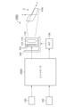
- FIG. 1 is a block diagram of a lighting system according to Embodiment 1.
- FIG. 2(a) and 2(b) are diagrams for explaining the pitch angle ⁇ p of the vehicle body. It is a functional block diagram of a controller. It is a figure which shows an example of the driving
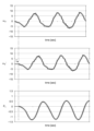
- 5 is a diagram showing waveforms of a dynamic pitch angle ⁇ d and a correction amount ⁇ V corresponding to the driving scene of FIG. 4;
- FIG. FIG. 5 is a diagram showing light rays corresponding to the cutoff line of the headlamp light in the driving scene of FIG. 4 ;
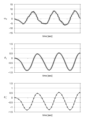
- FIGS. 7A to 7C are diagrams showing examples of the relationship (control characteristics) between the dynamic pitch angle ⁇ d and the correction amount ⁇ V.
- FIGS. 9A to 9C are diagrams showing examples of the relationship (control characteristics) between the dynamic pitch angle ⁇ d and the correction amount ⁇ V. It is a figure explaining optical axis correction based on the control characteristic of Fig.9 (a).
- FIGS. 11A to 11D are diagrams showing examples of the relationship (control characteristics) between the dynamic pitch angle ⁇ d and the correction amount ⁇ V.
- FIGS. 12A to 12C are diagrams for explaining an example of controlling the intensity distribution of light distribution.
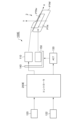
- FIG. 8 is a block diagram of a lighting system according to Embodiment 2; 3 is a functional block diagram of a controller according to Embodiment 1; FIG.
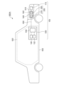
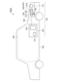
- FIG. 11 is a functional block diagram of a controller according to Example 3; 1 is a diagram illustrating an example of a vehicle design with a lighting system; FIG. FIG. 4 is a diagram showing another example of a vehicle design with a lighting system; FIG. 19 illustrates signal transmission and processing in the design of FIG. 18; FIG. 20 illustrates signal transmission and processing in the design of FIG. 19; It is a figure explaining prediction of the 1st pitch angle thetaj based on FFT. It is a figure which shows an example of the structure of a headlamp.
- FIG. 11 is a functional block diagram of a controller according to Example 3; 1 is a diagram illustrating an example of a vehicle design with a lighting system; FIG. FIG. 4 is a diagram showing another example of a vehicle design with a lighting system; FIG. 19 illustrates signal transmission and processing in the design of FIG. 18; FIG. 20 illustrates signal transmission and processing in the design of FIG. 19; It is a figure explaining prediction of the 1st pitch angle thetaj based
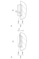
- FIG. 10 is a diagram illustrating yet another example of a vehicle design with a lighting system; It is a figure which shows an example of the structure of a headlamp. It is a figure which shows an example of the structure of a headlamp. It is a figure which shows an example of the structure of a headlamp. It is a figure which shows an example of the structure of a headlamp. 1 is a block diagram of a lighting system that supports hybrid leveling control; FIG. FIG. 4 is a diagram for explaining hybrid control of electronic leveling and mechanical leveling; 3 is a block diagram showing a configuration example of a controller of the lamp system; FIG. 1 is a block diagram of a lighting system that supports hybrid leveling control; FIG. FIGS. 32(a) and 32(b) are diagrams for explaining light distribution control by the lamp system of FIG. FIG. 32 is a diagram showing an example of the structure of the lamp system of FIG. 31; 32 is a perspective view of the lighting system of FIG. 31; FIG.
- a lighting fixture system includes a variable light distribution lamp that includes a plurality of individually controllable pixels and emits lamp light having a light distribution according to the states of the plurality of pixels;
- a position-controllable leveling actuator and a controller for controlling the leveling actuator and the variable light distribution lamp according to the pitch angle of the vehicle body are provided.
- the controller may control the leveling actuator according to the static component of the pitch angle of the vehicle body, and control the variable light distribution lamp according to the dynamic component of the pitch angle of the vehicle body.
- the lighting system may further include a first sensor including a gyro sensor.
- the controller may control the variable light distribution lamp according to the output of the first sensor.
- the lighting system may further include a second sensor including a vehicle height sensor or an acceleration sensor.
- the controller may control the leveling actuator according to the output of the second sensor.
- the lighting system may further include a fixed light distribution lamp that forms a fixed light distribution, and a lamp bracket that supports the fixed light distribution lamp and the variable light distribution lamp.
- a leveling actuator may be capable of controlling the position of the lamp bracket.
- a state in which member A is connected to member B refers to a case in which member A and member B are physically directly connected, and that member A and member B are electrically connected to each other. It also includes the case of being indirectly connected through other members that do not substantially affect the physical connection state or impair the functions and effects achieved by their combination.
- the state in which member C is provided between member A and member B refers to the case where member A and member C or member B and member C are directly connected, as well as the case where they are electrically connected. It also includes the case of being indirectly connected through other members that do not substantially affect the physical connection state or impair the functions and effects achieved by their combination.
- FIG. 1 is a block diagram of a lighting system 100 according to the first embodiment.
- the lighting system 100 is a headlamp that is mounted on a vehicle and that illuminates a field of view in front of the vehicle with light.
- An automobile changes its tilt angle in the front-rear direction according to the weight balance in the front-rear direction.
- the tilt angle in the longitudinal direction corresponds to the rotation of the vehicle body about the horizontal axis extending in the left and right direction, and is called the pitch angle ⁇ p.
- the lighting system 100 has a function (auto-leveling function) of automatically adjusting the optical axis of the headlamp in the pitch direction according to the pitch angle ⁇ p.
- the lamp system 100 includes a high-definition lamp unit 110, a sensor 120 and a controller 200.
- the high-definition lamp unit 110 is a variable light distribution lamp configured to irradiate part or all of the low beam area.
- the high-definition lamp unit 110 may cover part/all of the high beam area in addition to part/all of the low beam area.
- the high-definition lamp unit 110 includes a plurality of individually controllable pixels PIX, and emits lamp light having light distribution according to the states of the plurality of pixels PIX.
- high-definition lamp unit 110 includes light-emitting element array 112 and illumination optical system 114 .
- An LED array can be used as the light emitting element array 112 .
- the brightness of each pixel PIX may be controllable with two gradations of ON and OFF, or may be controllable with multiple gradations.
- PWM dimming can be used to achieve multiple gradations. may be expressed.
- the irradiation optical system 114 projects the output light of the light emitting element array 112 forward of the vehicle.
- the irradiation optical system 114 may be a lens optical system, a reflective optical system, or a combination thereof.
- a virtual vertical screen 2 is shown in FIG. It is assumed that the virtual vertical screen 2 is a coordinate system based on the road surface. The distance between the virtual vertical screen 2 and the vehicle (lamp) can be 10m or 25m.
- a light distribution pattern PTN is formed on the virtual vertical screen 2 by the lighting of the high-definition lamp unit 110 .
- the light distribution pattern PTN is the intensity distribution of lamp light on the virtual vertical screen 2 and is based on the on/off pattern of the plurality of pixels PIX of the light emitting element array 112 .
- the correspondence between the position of a certain pixel and the irradiation area on the virtual vertical screen 2 corresponding to that pixel is determined by the irradiation optical system 114, and is a mirror image relationship (horizontal inversion), vertical inversion, or vertical and horizontal inversion. Sometimes it is.
- the light distribution pattern PTN includes a cutoff line CL.
- the light distribution pattern PTN includes a horizontal cutoff line CLa and an oblique cutoff line CLb, which intersect at the elbow point LB.
- the controller 200 corrects the optical axis of the low beam in the pitch angle direction according to variations in the pitch angle ⁇ p caused by various factors while the vehicle is stationary and running.
- FIGS. 2(a) and 2(b) are diagrams for explaining the pitch angle ⁇ p of the vehicle body.
- FIG. 2(a) shows the pitch angle ⁇ p when the vehicle is stopped.
- the pitch angle ⁇ p when the vehicle is stationary is defined as a static pitch angle ⁇ s. Since the static pitch angle ⁇ s indicates the attitude of the vehicle when the vehicle is stopped, it is also referred to as the stationary vehicle attitude angle.
- the static pitch angle ⁇ s is determined according to the number of passengers, the riding position, the weight of luggage in the luggage compartment, the hardness of the front and rear suspensions, and the like.
- the angle formed by the straight line 12 parallel to the road surface 10 and the reference line 22 of the vehicle body 20 is taken as the pitch angle ⁇ p, and the upward direction of the reference line 22 (nose-up direction) is taken as positive. It is assumed that
- FIG. 2(b) shows the pitch angle ⁇ p while the vehicle is running.
- the pitch angle ⁇ p while the vehicle is running can be grasped as the sum of the static pitch angle ⁇ s and the dynamic component (also referred to as the dynamic pitch angle or pitch angle fluctuation amount) ⁇ d.
- the dynamic pitch angle ⁇ d can include the following components. ⁇ (i) Nose up due to vehicle acceleration, nose down due to deceleration ⁇ (ii) Changes in vehicle weight (weight balance) caused by road surface inclination ⁇ (iii) Fast vehicle vibration caused by uneven road surface
- vibrations of the vehicle body caused by unevenness of the road surface are generally within the range of 0.5 to 5 Hz, although they depend on the hardness of the suspension and the weight of the vehicle.
- a sharp vehicle body vibration is 0.9 to 2 Hz.
- the frequency component exceeding 0.5 Hz of the pitch angle fluctuation (generally 0.5 to 5 Hz, for example 1 to 2 Hz), which was conventionally removed as noise, is not removed as noise, and is actively subject to correction.
- optical axis correction for correcting pitch angle fluctuations during running is referred to as dynamic leveling.
- the sensor 120 is provided so as to detect the dynamic component ⁇ d of the pitch angle ⁇ p while the vehicle body is running.
- the senor 120 includes a gyro sensor.
- the gyro sensor may be attached in any direction, but is preferably installed so that one of its detection axes faces the left-right horizontal direction of the vehicle body, and generates a detection signal S1 indicating the angular velocity ⁇ p of rotational motion around this detection axis.
- the gyro sensor may be triaxial or uniaxial.
- the controller 200 is an ECU (Electronic Control Unit) that integrates functions related to optical axis correction, and performs processing related to dynamic leveling.
- the controller 200 may be an ECU dedicated to leveling (also referred to as a leveling ECU), an ECU integrated with a controller having other functions, or divided into a plurality of ECUs. good.
- the functions of the controller 200 may be realized by software processing, hardware processing, or a combination of software processing and hardware processing. Specifically, software processing is implemented by combining processors (hardware) such as CPU (Central Processing Unit), MPU (Micro Processing Unit), and microcontrollers, and software programs executed by the processor (hardware). . Controller 200 may be a combination of multiple processors (microcontrollers).
- hardware processing is implemented by hardware such as ASIC (Application Specific Integrated Circuit), controller IC, and FPGA (Field Programmable Gate Array).
- ASIC Application Specific Integrated Circuit
- controller IC controller IC
- FPGA Field Programmable Gate Array
- the controller 200 detects the dynamic component ⁇ d of the pitch angle ⁇ p while the vehicle is running by integrating the angular velocity ⁇ p indicated by the detection signal S1.
- the dynamic component ⁇ d here can be regarded as a component included in a predetermined frequency band higher than 0.5 Hz among variations in the pitch angle ⁇ p.
- components included in a predetermined frequency band are subject to correction as dynamic components.
- the predetermined frequency band can be set, for example, within a range of approximately 0.5 Hz to 5 Hz. Which frequency band is to be corrected may be determined based on the stiffness of the suspension, the mass of the vehicle body, and the like.
- the controller 200 adjusts the position of the cutoff line CL of the light distribution pattern PTN (the position in the vertical direction V, that is, the optical axis) to a predetermined position v 0 according to the dynamic component ⁇ d of the pitch angle ⁇ p of the running vehicle body. as a reference.
- Conventional leveling control moves the optical axis only downward for the purpose of suppressing glare.
- the position of the cutoff line CL is positively moved not only downward but also upward.
- the position of the cutoff line CL can be controlled by (1) fixing the lower end of the light distribution of the lamp and changing only the position of the cutoff line vertically, or (2) controlling the position of the lower end of the light distribution of the lamp. is varied vertically following the position of the cutoff line, in other words, the entire light distribution of the lamp is moved vertically.
- the controller 200 moves the cutoff line CL downward in response to the positive dynamic pitch angle ⁇ d. Further in this embodiment, the controller 200 positively moves the cutoff line CL upward in response to the negative dynamic pitch angle ⁇ d.
- the controller 200 moves the position of the cutoff line CL upward and downward with respect to the predetermined position V0 so as to cancel the dynamic component ⁇ d of the pitch angle ⁇ p.
- the predetermined position V0 is the vertical coordinate at which the cutoff line CL should be located when the variation of the pitch angle ⁇ p is zero.
- the controller 200 changes the on/off boundaries 116 of the plurality of pixels PIX of the light emitting element array 112 in order to raise or lower the cutoff line CL on the virtual vertical screen 2 .
- How many pixels the boundary 116 is to be shifted for a given variation range of the pitch angle ⁇ p can be determined geometrically. Let ⁇ y be the pixel shift amount.
- FIG. 3 is a functional block diagram of the controller 200.
- the controller 200 includes a pitch angle calculator 210 and a cutoff line controller 220 .
- the pitch angle calculator 210 detects the dynamic component ⁇ d of the pitch angle ⁇ p based on the output of the sensor 120 .
- the pitch angle calculator 210 integrates the angular velocity ⁇ p indicated by the detection signal S1.
- the pitch angle calculation unit 210 calculates the dynamic pitch angle ⁇ d by performing calculation processing on the integrated value as necessary. This arithmetic processing can include filtering (band limiting processing), moving average processing, and the like.
- the cutoff line control unit 220 raises and lowers the position of the cutoff line CL based on the dynamic pitch angle ⁇ d.
- Cut-off line control section 220 includes correction amount calculation section 222 and correction section 224 .
- the correction amount calculator 222 calculates the amount of vertical movement (correction amount ⁇ V) of the cutoff line CL on the virtual vertical screen 2 based on the dynamic pitch angle ⁇ d.
- a positive correction amount ⁇ V corresponds to an upward shift of the cutoff line CL
- a negative correction amount ⁇ V corresponds to a downward shift of the cutoff line CL.
- the correction unit 224 controls the light emitting element array 112 so that the cutoff line CL moves by the correction amount ⁇ V.
- the light-emitting element array 112 has an interface for inputting image data that designates on/off (or luminance) of a plurality of pixels PIX.
- the correction unit 224 may shift the position of the boundary 116 between ON pixels and OFF pixels included in the image data up and down by the number of pixels ⁇ y corresponding to the correction amount ⁇ V. That is, the correction unit 224 shifts the position (boundary 116) of the cutoff line CL of the light distribution pattern included in the image data upward and downward with respect to the predetermined position y0 so as to cancel the dynamic component ⁇ d of the pitch angle ⁇ p. Move downward.
- the predetermined position y0 is a reference position corresponding to V0 .
- the correction unit 224 determines the position (height) of the boundary between the ON and OFF pixels corresponding to the lower end of the light distribution pattern. may be shifted up and down by the number of pixels ⁇ y corresponding to the correction amount ⁇ V. That is, the correction unit 224 may shift the entire light distribution pattern vertically by the number of pixels ⁇ y corresponding to the correction amount ⁇ V.
- the configuration of the lamp system 100 is as described above. Next, the operation will be explained.
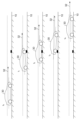
- FIG. 4 is a diagram showing an example of a vehicle traveling scene.
- the vehicle 30 is traveling from left to right on the paper surface, and shows how it climbs over a step 14 on the road surface 10 .
- FIG. 4 shows attitudes of the vehicle 30 at a plurality of times t 0 to t 4 . Each time t 0 to t 4 indicates the following states.
- Time t0 The vehicle is running in front of the step 14
- Time t1 The front wheels have run over the step 14
- Time t2 The front wheels have run over the step 14
- Time t3 The rear wheels have run over the step 14
- State Time t 4 The state where the rear wheels have run over the step 14
- the dynamic pitch angle ⁇ d is 0 at times t 0 , t 2 and t 4 .
- the dynamic pitch angle ⁇ d at time t1 takes a positive value ⁇ d1
- the dynamic pitch angle ⁇ d at time t2 takes a negative value ⁇ d3 .
- FIG. 5 is a diagram showing the waveform of the dynamic pitch angle ⁇ d and the waveform of the correction amount ⁇ V corresponding to the driving scene of FIG. As shown in FIG. 4, the dynamic pitch angle ⁇ d swings in the positive direction, swings in the negative direction, and eventually returns to 0.
- a correction amount ⁇ V is generated corresponding to the variation of the dynamic pitch angle ⁇ d.
- FIG. 6 is a diagram showing light rays corresponding to the cutoff line of the headlamp light in the driving scene of FIG.
- the light beam 32 of the lamp light can always be kept at a constant angle with respect to the road surface 10 by adaptive light distribution control following the dynamic pitch angle ⁇ d.
- the lamp system 100 when the rear of the vehicle 30 sinks as shown at time t1 in FIG. 6, glare can be prevented by lowering the cut-off line. Also, as shown at time t3 in FIG. 6, when the front of the vehicle 30 sinks, raising the cutoff line can prevent the distant field of vision from becoming dark.
- the position of the cut-off line on the virtual vertical screen in front of the vehicle is can be kept constant at all times, preventing objects in front of the vehicle from brightening or darkening, thus providing an improved field of vision.
- the static pitch angle ⁇ s can be regarded as a reference value of the pitch angle ⁇ p
- the dynamic pitch angle ⁇ d can be regarded as a dynamic deviation from the reference value of the pitch angle ⁇ p. Therefore, the controller 200 controls the high-definition lamp unit 110 so that the angle formed by the light beam 32 corresponding to the cutoff line of the lamp light and the road surface 10 is constant according to the deviation ⁇ d.
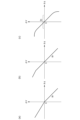
- FIG. 7(a) to (c) are diagrams showing examples of the relationship (control characteristics) between the dynamic pitch angle ⁇ d and the correction amount ⁇ V.
- the correction amount ⁇ V is expressed as a linear expression having a proportionality constant (referred to as a reference gain g0 ) based on the distance L with respect to the dynamic pitch angle ⁇ d. can be determined.
- a reference gain g0 a proportionality constant
- the boundary 116 corresponding to the cutoff line on the image data is vertically shifted so as to obtain the correction amount ⁇ V shown in FIG.
- the illumination optical system 114 is a complex optical system including a reflector having a hyperbolic paraboloid, an elliptical paraboloid, a paraboloid of revolution, and a free paraboloid
- the correction amount ⁇ V may be defined by a polygonal line with respect to the dynamic pitch angle ⁇ d.
- a control characteristic such as (b) may be defined. In this case, it is possible to suppress glare when a control delay occurs in a situation where the nose-up posture is assumed immediately after the nose dive.
- the irradiation optical system 114 is a complex optical system that includes a reflecting mirror having an elliptical paraboloid or a free paraboloid, as shown in FIG. may
- the upward movement of the cutoff line may be disabled.
- the dynamic pitch angle ⁇ d includes a frequency component that exceeds the response speed of the controller 200, glare can be suppressed by invalidating the movement of the cutoff line in the upward direction.
- movement of the cut-off line not only in the upward direction but also in the downward direction may be invalidated.
- road surface unevenness occurs continuously (for example, for 3 seconds or longer)
- the road surface is a special road surface (for example, a dirt course, an unpaved mountain road, etc.) that is different from normal road driving. Therefore, when a steep pitch angle change occurs continuously for a predetermined period of time (for example, 3 seconds), the pitch angle control may be fixed to the pitch angle control acquired while the vehicle is stopped or in a stable running state. Also, when returning, it is better not to return it immediately, but gradually return it over a period of several seconds.
- the high-definition lamp unit 110 capable of controlling the intensity distribution with multiple gradations, it is preferable to apply blurring or gradation to restore the intensity gradually.
- FIG. 8 is a diagram for explaining glare that may occur as a result of optical axis correction during nosedive.
- the vehicle 30 is traveling from left to right on the paper and is shown passing through a dent 16 on the road surface 10 .
- FIG. 4 shows attitudes of the vehicle 30 at a plurality of times t 0 to t 4 . Each time t 0 to t 4 indicates the following states.
- Time t 0 The vehicle is running in front of the dent 16
- Time t 1 The front wheel has fallen into the dent 16
- Time t 2 The front wheel has passed the dent 16
- Time t 3 The rear wheel is in the dent 16 Falling state
- Time t 4 State where the rear wheel has passed through the dent 16
- the controller 200 attempts to return the cutoff line to the original predetermined position v0 . However, if there is a control delay, the cut-off line will not return to the predetermined position v0 and will be positioned above the predetermined position v0 . This causes the lamp light to be emitted above the horizontal, which may give rise to glare.
- the controller 200 attempts to correct the position of the cutoff line downward from the predetermined position v0 so that the optical axis faces downward. In this case as well, if there is a control delay, the cutoff line will not fall completely to the target position corresponding to the current attitude, so the lamp light will be emitted above the horizontal plane, possibly giving glare.
- the dynamic pitch angle ⁇ d is positive and negative, in other words, when the cutoff line CL moves upward from the predetermined position and when the cutoff line CL moves upward from the predetermined position.
- the control characteristics were the same when moving downward.
- asymmetry is introduced according to the sign (orientation) of the dynamic pitch angle ⁇ d.
- control characteristic is the relationship between the dynamic pitch angle ⁇ d and the correction amount ⁇ V, and is exemplified by the above-mentioned function f( ) and the parameters (gain and order) that define it.
- FIG. 9(a) to (c) are diagrams showing examples of the relationship (control characteristics) between the dynamic pitch angle ⁇ d and the correction amount ⁇ V.
- the control characteristic is a linear function as in FIG. 7(a), but the gain (slope ) are different.
- the correction amount ⁇ V is relatively large when ⁇ d>0, and the correction amount ⁇ V is relatively large when ⁇ d ⁇ 0. It can be small.
- the slope is smaller than the slope based on the reference gain g0 compared to ⁇ d>0.
- the amount by which the optical axis is directed upward is suppressed. This makes it possible to suppress the glare given to surrounding traffic participants when a control delay occurs in a situation where the nose-up posture is assumed immediately after a nose dive. That is, the problem described with reference to FIG. 8 can be solved.
- FIG. 10 is a diagram for explaining optical axis correction based on the control characteristics of FIG. 9(a).
- FIG. 10 shows the same driving scene as in FIG. 8 with the control characteristics shown in FIG. 9(a) applied.
- the position of the cutoff line is corrected so that the optical axis faces upward.
- the correction amount ⁇ V is smaller than the correction amount in FIG.
- the dashed-dotted line is the optical axis in FIG. 8, and the solid line is the optical axis based on the control characteristics in FIG. 9(a).
- the controller 200 attempts to return the cutoff line to the original predetermined position v0 . Since the correction amount ⁇ V for the previous nose dive is small, the cutoff line returns to the predetermined position v0 even if there is a control delay. As a result, the lamp light is maintained below the horizontal, and glare can be suppressed.
- a negative threshold value ⁇ TH is defined, and in the range of ⁇ d> ⁇ TH , there is a slope based on the reference gain g0 .
- the slope is smaller than that based on the reference gain g0 .
- the transfer function can include a filter element.
- the characteristics of the filter may be different when moving upward and when moving downward from a predetermined position.
- FIGS. 11(a) to 11(d) are diagrams showing examples of the relationship (control characteristics) between the dynamic pitch angle ⁇ d and the correction amount ⁇ V.
- the frequency characteristics (cutoff frequency) are the same for ⁇ d>0 and ⁇ d ⁇ 0, and only the gain g is different.
- the gain is the reference gain g0 when ⁇ d>0 and when ⁇ d ⁇ 0, but the frequency characteristics are different. Specifically, when ⁇ d>0 (nose up), the wide frequency band of the dynamic pitch angle ⁇ d is corrected to reliably prevent glare. When ⁇ d ⁇ 0 (nose dive), the frequency band for correcting the dynamic pitch angle ⁇ d is narrowed. This reduces the risk of glare due to control delays.
- the gain is the reference gain g0 when .theta.d>0 and when .theta.d ⁇ 0, but the frequency characteristics are different.
- ⁇ d ⁇ 0 nose dive
- the frequency band for correcting the dynamic pitch angle ⁇ d is narrowed, but the band to be corrected is wider than in FIG. 11(b). side.
- both the gain g and the frequency characteristic differ between when ⁇ d>0 and when ⁇ d ⁇ 0.
- the speed at which the cutoff line CL is raised and lowered may be changed according to the attitude of the vehicle body. Specifically, the speed at which the cutoff line moves upward may be slower than the speed at which the cutoff line moves downward. This makes it difficult to give glare after the cutoff line CL is corrected upward.
- the upward movement of the cut-off line may be disabled.
- the dynamic pitch angle ⁇ d includes a frequency component that exceeds the response speed of the controller 200, glare can be suppressed by invalidating the movement of the cutoff line in the upward direction.
- movement of the cut-off line not only in the upward direction but also in the downward direction may be invalidated.
- road surface unevenness occurs continuously (for example, for 3 seconds or longer)
- the road surface is a special road surface (for example, a dirt course, an unpaved mountain road, etc.) that is different from normal road driving. Therefore, when a steep pitch angle change occurs continuously for a predetermined period of time (for example, 3 seconds), the pitch angle control may be fixed to the pitch angle control acquired while the vehicle is stopped or in a stable running state. Also, when returning, it is better not to return it immediately, but gradually return it over a period of several seconds.
- the high-definition lamp unit 110 capable of controlling the intensity distribution with multiple gradations, it is preferable to apply blurring or gradation to restore the intensity gradually.
- the controller 200 may change the intensity distribution (illuminance distribution) of the light distribution in addition to moving the cutoff line (leveling control).
- FIGS. 12(a) to 12(c) are diagrams for explaining an example of controlling the intensity distribution of light distribution.
- FIG. 12(a) is an example of the most standard light distribution control, in which only the cutoff line CL is moved upward, and the illuminance is substantially constant.
- the illuminance is indicated by hatching density, and the higher the density, the higher the illuminance.
- the controller 200 sets the illuminance in the range above the predetermined position v0 to lower than the illuminance (specified value) at that time. As a result, it is possible to prevent glare from occurring while ensuring the driver's distant field of vision.
- the intensity distribution of the light distribution is such that when the cutoff line CL is located above the predetermined position V0 , the illuminance in the range above the predetermined position V0 increases upward. It has a gradation that gets darker gradually. As a result, it is possible to prevent glare from occurring while ensuring the driver's distant field of vision.
- the gyro sensor detects the dynamic component of the pitch angle in the embodiments, the present disclosure is not limited thereto.
- the dynamic component of the pitch angle may be detected based on a combination of a front vehicle height sensor provided on the front suspension of the vehicle body and a rear vehicle height sensor provided on the rear suspension of the vehicle body.
- high-definition lamp unit 110 is configured with the light-emitting element array 112 in the embodiment, the present disclosure is not limited thereto.
- high definition lamp unit 110 may include a light source that produces light having a substantially flat intensity distribution and a spatial light modulator that spatially patterns the light emitted by the light source.
- Spatial light modulators are exemplified by DMDs (Digital Micromirror Devices) and liquid crystal devices.
- the method by which the controller 200 vertically shifts the position of the cutoff line CL is not limited to that described in the embodiment.
- the light emitting element array 112 may have a pixel shift function.
- the light-emitting element array 112 may be provided with reference image data and a pixel shift amount ⁇ y.
- Control of the optical axis that is, control of the height of the cutoff line is not limited to pixel control (electronic leveling) of the high-definition lamp unit 110 .
- a normal low beam unit may be configured to be controllable by a high-speed leveling actuator, and the height of the cutoff line may be controlled by changing the inclination of the low beam unit (referred to as mechanical leveling).
- the position of the light emitting element array 112 may be configured to be mechanically shiftable.
- FIG. 13 is a block diagram of the lamp system 100 according to the second embodiment.
- the lighting system 100 is a headlamp that is mounted on a vehicle and that illuminates a field of view in front of the vehicle.
- An automobile changes its tilt angle in the front-rear direction according to the weight balance in the front-rear direction.
- the tilt angle in the longitudinal direction corresponds to the rotation of the vehicle body about the horizontal axis extending in the left and right direction, and is called the pitch angle ⁇ p.
- the lighting system 100 has a function (auto-leveling function) of automatically adjusting the optical axis of the headlamp in the pitch direction according to the pitch angle ⁇ p.
- the lamp system 100 includes a high-definition lamp unit 110, a first sensor 120, a second sensor, and a controller 200.
- the high-definition lamp unit 110 is a variable light distribution lamp configured to irradiate part or all of the low beam area.
- the high-definition lamp unit 110 may cover part/all of the high beam area in addition to part/all of the low beam area.
- the high-definition lamp unit 110 includes a plurality of individually controllable pixels PIX, and emits lamp light having light distribution according to the states of the plurality of pixels PIX.
- high-definition lamp unit 110 includes light-emitting element array 112 and illumination optical system 114 .
- An LED array can be used as the light emitting element array 112 .
- the brightness of each pixel PIX may be controllable with two gradations of ON and OFF, or may be controllable with multiple gradations.
- PWM dimming can be used to achieve multiple gradations. may be expressed.
- the irradiation optical system 114 projects the output light of the light emitting element array 112 forward of the vehicle.
- the irradiation optical system 114 may be a lens optical system, a reflective optical system, or a combination thereof.
- the virtual vertical screen 2 is shown in FIG. It is assumed that the virtual vertical screen 2 is a coordinate system based on the road surface. The distance between the virtual vertical screen 2 and the vehicle (lamp) can be 10m or 25m.
- a light distribution pattern PTN is formed on the virtual vertical screen 2 by the lighting of the high-definition lamp unit 110 .
- the light distribution pattern PTN is the intensity distribution of lamp light on the virtual vertical screen 2 and is based on the on/off pattern of the plurality of pixels PIX of the light emitting element array 112 .
- the correspondence between the position of a certain pixel and the irradiation area on the virtual vertical screen 2 corresponding to that pixel is determined by the irradiation optical system 114, and is a mirror image relationship (horizontal inversion), vertical inversion, or vertical and horizontal inversion. Sometimes it is.
- the light distribution pattern PTN includes a cutoff line CL.
- the light distribution pattern PTN includes a horizontal cutoff line CLa and an oblique cutoff line CLb, which intersect at the elbow point LB.
- the controller 200 corrects the optical axis of the low beam in the pitch angle direction according to variations in the pitch angle ⁇ p caused by various factors while the vehicle is stationary and running.
- the controller 200 changes the on/off boundaries 116 of the plurality of pixels PIX of the light emitting element array 112 in order to raise or lower the cutoff line CL on the virtual vertical screen 2 .
- How many pixels the boundary 116 is to be shifted for a given variation range of the pitch angle ⁇ p can be determined geometrically. Let ⁇ y be the pixel shift amount.
- the controller 200 performs dynamic leveling targeting frequency components exceeding 0.5 Hz of pitch angle fluctuations, which were conventionally removed as noise.
- the controller 200 also corrects the optical axis according to the static pitch angle (position angle of the stationary vehicle) ⁇ s shown in FIG. 2(a). Specifically, control is performed so that the light axis of the lamp is directed downward in response to changes in the static load of the vehicle while the vehicle is stopped. This is called static leveling. Static leveling is performed in conventional vehicle lamps using a G sensor (acceleration sensor) and a vehicle height sensor.
- G sensor acceleration sensor
- a first sensor 120 and a second sensor 122 are provided for accurate detection of the pitch angle ⁇ p in this embodiment.
- the first sensor 120 is provided so that it can mainly detect the dynamic component ⁇ d of the pitch angle ⁇ p during running of the vehicle body.
- the first sensor 120 includes a gyro sensor.
- the gyro sensor may be attached in any direction, but is preferably attached so that one of its detection axes faces the left-right horizontal direction of the vehicle body, and generates a first detection signal S1 indicating the angular velocity ⁇ p of rotational motion around this detection axis. do.
- the gyro sensor may be triaxial or uniaxial.
- the second sensor 122 is an acceleration sensor (G sensor).
- the second sensor 122 outputs a detection signal S2 containing accelerations ⁇ x , ⁇ y and ⁇ z with respect to each of the three axes.
- the resultant vector of the three-axis accelerations ⁇ x , ⁇ y , and ⁇ z points in the direction of gravity.
- the composite vector of the three-axis accelerations ⁇ x , ⁇ y , and ⁇ z gives the composite vector of the gravity and the acceleration vector of the vehicle body.
- the first sensor 120 and the second sensor 122 may be six-axis sensors in which an acceleration sensor and a gyro sensor are integrated.
- the controller 200 is an ECU (Electronic Control Unit) that integrates functions related to optical axis correction, and performs processing related to static leveling and dynamic leveling.
- the controller 200 may be an ECU dedicated to leveling (also referred to as a leveling ECU), an ECU integrated with a controller having other functions, or divided into a plurality of ECUs. good.
- the functions of the controller 200 may be realized by software processing, hardware processing, or a combination of software processing and hardware processing. Specifically, software processing is implemented by combining processors (hardware) such as CPU (Central Processing Unit), MPU (Micro Processing Unit), and microcontrollers, and software programs executed by the processor (hardware). . Controller 200 may be a combination of multiple processors (microcontrollers).
- hardware processing is implemented by hardware such as ASIC (Application Specific Integrated Circuit), controller IC, and FPGA (Field Programmable Gate Array).
- ASIC Application Specific Integrated Circuit
- controller IC controller IC
- FPGA Field Programmable Gate Array
- the controller 200 detects the pitch angle ⁇ p of the vehicle according to the detection signal S1 generated by the first sensor 120 and the second detection signal S2 generated by the second sensor 122, and adjusts the distribution according to the pitch angle ⁇ p. Controls the height of the light cutoff line.
- the pitch angle .theta.p includes the static pitch angle .theta.s (position angle of the stationary vehicle) and the dynamic pitch angle .theta.p.
- FIG. 14 is a functional block diagram of the controller 200A according to the first embodiment.
- the controller 200A includes a pitch angle calculator 210 and a cutoff line controller 220 .
- the pitch angle calculator 210 generates angle information necessary for optical axis correction (leveling control), that is, the pitch angle ⁇ p, based on the two detection signals S1 and S2.
- the pitch angle calculator 210 includes an integrator 212 and an acceleration direction calculator 214 .
- the integrator 212 calculates the first pitch angle ⁇ j by integrating the angular velocity ⁇ p indicated by the first detection signal S1.
- the acceleration direction calculator 214 calculates a second pitch angle ⁇ a indicating the acceleration direction ⁇ based on the accelerations ⁇ x , ⁇ y , and ⁇ z indicated by the second detection signal S2.
- FIG. 15 is a diagram explaining the second pitch angle ⁇ a.
- the direction of acceleration ⁇ detected by the direction-of-acceleration calculator 214 coincides with the direction of gravity G when the vehicle is stopped or in uniform motion.
- the x, y, and z axes of the acceleration sensor are assumed to be parallel to the X, Y, and Z axes of the vehicle body. It is assumed that the X-axis of the vehicle body faces the traveling direction, the Y-axis faces the horizontal direction, and the Z-axis faces the vertical direction. For ease of understanding, it is assumed that no acceleration occurs in the y direction.
- the second pitch angle ⁇ a is taken as the angle between the z-axis of the acceleration sensor and the acceleration vector ⁇ . Then, the second pitch angle ⁇ a becomes the angle formed by the straight line parallel to the road surface and the X-axis of the vehicle body, and coincides with the stationary pitch angle ⁇ s shown in FIG. 2(a).
- Pitch angle calculator 210 can include a filter (low-pass filter or band-pass filter) to remove noise components. It should be determined so that the components can pass through. Therefore, the cutoff frequency should be set between the noise frequency and the maximum frequency of the frequencies to be corrected. For example, when the noise component around 100 Hz is large, the cutoff frequency must be determined so as to sufficiently attenuate 100 Hz, and may be set to about 1/2 to 1/3 of the noise frequency of 100 Hz, for example 50 Hz.
- the second pitch angle ⁇ a is associated with the static pitch angle ⁇ s
- the first pitch angle ⁇ j is associated with the dynamic pitch angle ⁇ d.
- the static pitch angle ⁇ s stop vehicle attitude angle
- the acceleration sensor acquires the direction and inclination of the gravitational acceleration, it cannot distinguish whether the vehicle is leaning on a slope or is leaning due to a load, even when the vehicle is stopped. can be used to estimate the stationary vehicle attitude angle (static pitch angle ⁇ s).
- the first pitch angle ⁇ j can be set to the dynamic pitch angle ⁇ d. For example, if the integral value is reset while the angular velocity ⁇ p in the pitch direction is 0 continues, and the integration is started when the angular velocity ⁇ p becomes non-zero, the integral value will be the dynamic pitch angle ⁇ d. will be shown.
- the cut-off line control unit 220 performs static leveling based on the static pitch angle ⁇ s and dynamic leveling based on the dynamic pitch angle ⁇ p. For example, the cutoff line control unit 220 controls the position V0 , which is the reference of the cutoff line CL, based on the static pitch angle ⁇ s. The cut-off line control unit 220 also shifts the cut-off line CL vertically with reference to the reference position V0 based on the dynamic pitch angle ⁇ d.
- Dynamic leveling may be applied only when the dynamic pitch angle ⁇ p based on the first pitch angle ⁇ j is greater than a predetermined threshold.
- Two methods of leveling control by the cut-off line control unit 220 are conceivable.
- One is a method of directly controlling the optical axis based on the pitch angle ⁇ p. This is called collective control.
- the position of the cutoff line CL may be set using the pitch angle ⁇ p as the control angle.
- the pitch angle ⁇ p can be generated by adding ⁇ j and ⁇ s.
- Another leveling control is a method of controlling the optical axis by separating the static pitch angle ⁇ s and the dynamic pitch angle ⁇ d. This is called separate control. Separation control will be described below.
- Cut-off line control section 220 includes correction amount calculation section 222 and correction section 224 .
- the correction amount calculation unit 222 calculates the position V0 as the reference of the cutoff line CL on the virtual vertical screen 2 based on the static pitch angle ⁇ s. Further, the correction amount calculation unit 222 calculates the vertical movement amount (correction amount ⁇ V) of the cutoff line CL based on the dynamic pitch angle ⁇ d.
- a positive correction amount ⁇ V corresponds to an upward shift of the cutoff line CL
- a negative correction amount ⁇ V corresponds to a downward shift of the cutoff line CL.
- the correction unit 224 controls the light emitting element array 112 to move the cutoff line CL from the reference position V0 by the correction amount ⁇ V.
- the light-emitting element array 112 has an interface for inputting image data that designates on/off (or luminance) of a plurality of pixels PIX.
- the correction unit 224 may shift the position of the boundary 116 between ON pixels and OFF pixels included in the image data up and down by the number of pixels ⁇ y corresponding to the correction amount ⁇ V. That is, the correction unit 224 adjusts the cutoff line position (boundary 116) of the light distribution pattern included in the image data upward and downward with respect to the predetermined position y0 so as to cancel the dynamic component ⁇ d of the pitch angle ⁇ p. move in the direction
- the predetermined position y0 is a reference position corresponding to V0 .
- the correction unit 224 determines the position (height) of the boundary between the ON and OFF pixels corresponding to the lower end of the light distribution pattern. may be shifted up and down by the number of pixels ⁇ y corresponding to the correction amount ⁇ V. That is, the correction unit 224 may shift the entire light distribution pattern vertically by the number of pixels ⁇ y corresponding to the correction amount ⁇ V.
- Example 2 The basic configuration of the controller according to Example 2 is the same as in FIG.
- the static pitch angle ⁇ s is determined based on the second pitch angle ⁇ a. That is, static leveling is the same as in the first embodiment.
- the second embodiment differs from the first embodiment in dynamic leveling. Specifically, the dynamic pitch angle ⁇ d used in dynamic leveling is determined based on the variation of not only the first pitch angle ⁇ j but also the second pitch angle ⁇ a.
- FIG. 16 is a diagram showing the second pitch angle ⁇ a sensed by the second sensor 122.
- FIG. Section T1 indicates that the vehicle is stopped on a non-sloping road surface.
- the second pitch angle ⁇ a while the vehicle is stopped indicates the static pitch angle (position angle of the stopped vehicle) ⁇ s.
- Section T2 indicates running on a flat road.
- the second pitch angle ⁇ a slightly fluctuates, but is substantially constant.
- Section T3 indicates an uphill slope with an inclination of ⁇ 1.
- the second pitch angle ⁇ a is increased by ⁇ 1 from the stationary pitch angle ⁇ s.
- the change in the second pitch angle ⁇ a due to the slope does not affect the posture of the vehicle body, it is irrelevant to the dynamic pitch angle ⁇ d, and leveling control does not occur.
- Section T4 indicates a downhill with an inclination of ⁇ 2.
- the second pitch angle ⁇ a is decreased by ⁇ 2 from the stationary pitch angle ⁇ s.
- the change in the second pitch angle ⁇ a due to the slope does not affect the posture of the vehicle body, it is irrelevant to the dynamic pitch angle ⁇ d, and leveling control does not occur.
- a section T5 indicates an acceleration period. This acceleration is normal acceleration, and is distinguished from rapid acceleration, which will be described later. During the acceleration period, the nose rises and attitude changes occur. Thereby, the second pitch angle ⁇ a becomes larger than the stationary pitch angle ⁇ s.
- the cut-off line control unit 220 sets the variation width ⁇ a ⁇ s of the second pitch angle ⁇ a as the dynamic pitch angle ⁇ d, and corrects the optical axis based on the dynamic pitch angle ⁇ d. This is called slow dynamic leveling.
- Section T6 is running on an uneven road surface.
- the second pitch angle ⁇ a oscillates around the static pitch angle ⁇ s.
- the cut-off line control unit 220 sets the variation component ⁇ a ⁇ s of the second pitch angle ⁇ a as the dynamic pitch angle ⁇ d, and vertically moves the optical axis based on the dynamic pitch angle ⁇ d. This is called high-speed dynamic leveling.
- Leveling control may be performed based on one of ⁇ j and ( ⁇ a- ⁇ d). For example, when it is estimated that the second pitch angle ⁇ a contains noise, leveling control may be performed based on the first pitch angle ⁇ j.
- leveling control may be performed by averaging ⁇ j and ( ⁇ a- ⁇ d).
- FIG. 17 is a functional block diagram of a controller 200B according to the third embodiment.
- the controller 200A includes a pitch angle calculator 210 and a cutoff line controller 220, as in FIG.
- the pitch angle calculation unit 210 includes an integrator 212 and an acceleration direction calculation unit 214, as well as a synthesis unit 216 and a running condition determination unit 218.
- the synthesizing unit 216 synthesizes the first pitch angle ⁇ j and the second pitch angle ⁇ a to generate the pitch angle ⁇ p, which is angle information required for optical axis correction (leveling control).
- the pitch angle ⁇ p includes static pitch angle ⁇ s and dynamic pitch angle ⁇ d.
- the cut-off line control unit 220 may perform batch control or separate control, but here it is assumed that batch control is carried out.
- Synthesis unit 216 performs weighted addition of first pitch angle ⁇ j and second pitch angle ⁇ a to estimate pitch angle ⁇ p by equation (1).
- ⁇ p ⁇ j+ ⁇ a (1)
- the driving condition determination unit 218 determines driving conditions based on information from the vehicle (referred to as vehicle information) and/or based on sensor information.
- Vehicle information includes vehicle speed, steering angle, camera image, map information, infrastructure information, suspension setting, vehicle weight, and the like.
- the sensor information includes at least one of the first detection signal S1, the second detection signal S2, and the first pitch angle ⁇ j and the second pitch angle ⁇ a based thereon. Therefore, the weighting coefficient ⁇ can be set according to at least one of vehicle information and sensor information.
- the leveling control based on the output of the second sensor 122 is enabled. Conversely, under running conditions in which the first sensor 120 detects a steep pitch angle change, leveling control based on the first pitch angle ⁇ j is enabled to follow the high-speed pitch angle change.
- the pitch angle ⁇ p is calculated by setting ⁇ to approximately 0.1 to 0.5 and increasing the weighting of the acceleration sensor.
- the frequency of vibration caused by unevenness such as gravel is higher than 5 Hz, and can be, for example, 10-20 Hz.
- the frequency of vibration caused by unevenness such as gravel is higher than 5 Hz, and can be, for example, 10-20 Hz.
- ⁇ is set to approximately 0.1 to 0.5, and the weighting of the acceleration sensor is increased to calculate the pitch angle ⁇ p.
- frequencies higher than 5 Hz can be treated as noise, and control can be performed based on an average that does not include the noise, thereby reducing annoyance.
- ⁇ can be between 0.5 and 1.0. In this case, since the pitch angle is expected to change sharply, high-speed dynamic leveling becomes possible by increasing ⁇ and making the influence of the gyro sensor dominant.
- ⁇ can be between 0.5 and 1.0. In this case, since the pitch angle is expected to change sharply, high-speed dynamic leveling becomes possible by increasing ⁇ and making the influence of the gyro sensor dominant.
- ⁇ can be set to 0.5 to 1.0.
- the weighting of the gyro sensor can be increased, and dynamic leveling corresponding to the dynamic pitch angle fluctuations becomes possible.
- the combination of the first sensor 120 and the second sensor 122 can detect static attitude changes of the vehicle body (static pitch angle) due to the number of passengers, the weight of luggage, the weight of fuel, etc. changes), the inclination of the road surface on which the vehicle is running, and sharp fluctuations in the pitch angle due to unevenness and undulations present on the road surface can be detected separately.
- static attitude changes of the vehicle body static pitch angle
- the inclination of the road surface on which the vehicle is running can be detected separately.
- a vehicle height sensor may be used as the second sensor 122 instead of the acceleration sensor.
- the vehicle height sensor may be a rear vehicle height sensor only, or may be a hybrid of a rear vehicle height sensor and a front vehicle height sensor.
- high-definition lamp unit 110 is configured with the light-emitting element array 112 in the embodiment, the present disclosure is not limited thereto.
- high definition lamp unit 110 may include a light source that produces light having a substantially flat intensity distribution and a spatial light modulator that spatially patterns the light emitted by the light source.
- Spatial light modulators are exemplified by DMDs (Digital Micromirror Devices) and liquid crystal devices.
- the method by which the controller 200 vertically shifts the position of the cutoff line CL is not limited to that described in the embodiment.
- the light emitting element array 112 may have pixel shift functionality.
- the light-emitting element array 112 may be provided with reference image data and a pixel shift amount ⁇ y.
- Control of the optical axis that is, control of the height of the cutoff line is not limited to pixel control (electronic leveling) of the high-definition lamp unit 110 .
- a normal low beam unit may be configured to be controllable by a high-speed leveling actuator, and the height of the cutoff line may be controlled by changing the inclination of the low beam unit (referred to as mechanical leveling).
- the position of the light emitting element array 112 may be configured to be mechanically shiftable.
- electronic leveling may be applied for sharp pitch angle variations
- mechanical leveling may be applied for gradual or static pitch angle variations.
- control for directing the optical axis upward is limited to static leveling and low-speed dynamic leveling, and in the high-speed dynamic leveling, only the control for directing the optical axis downward is performed without upward control. good.
- FIG. 18 is a diagram showing a design example of a vehicle 500A that includes the lighting system 100. As shown in FIG. As described in the second embodiment, the lighting system 100 includes the high definition lamp unit 110, the controller 200, the first sensor 120 and the second sensor 122. FIG.
- the high-definition lamp unit 110 is built into the headlamp 510A.
- a first sensor 120 that is a gyro sensor and a second sensor 122 that includes an acceleration sensor or a vehicle height sensor are provided inside the vehicle interior 504 .
- the controller 200 includes a pitch angle calculator 210 and a cutoff line controller 220, as shown in FIG.
- the pitch angle calculation unit 210 and the cut-off line control unit 220 are implemented as the same hardware (calculation processing unit) on the headlamp 510A side.
- pitch angle calculation unit 210 and cut-off line control unit 220 are mounted in second calculation processing unit 542 provided on the side of headlamp 510A, that is, outside vehicle compartment 504 (inside the engine room).
- the second processing unit 542 may be part of a unit called control module 540 .
- the control module 540 can include, in addition to the second arithmetic processing section 542, a power supply circuit that supplies power to the high-definition lamp unit 110, and the like.
- the first arithmetic processing unit 532 and the second arithmetic processing unit 542 may be microcontrollers including software-controllable CPUs.
- the first sensor 120 and the first arithmetic processing section 532 are unitized and called a leveling ECU 530 . If the second sensor 122 is an acceleration sensor, the second sensor 122 can also be built into the leveling ECU 530 .
- the first sensor 120 and the second sensor 122 may be a 6-axis sensor 124 that integrates a gyro sensor and an acceleration sensor.
- the first arithmetic processing unit 532 inside the vehicle interior 504 and the second arithmetic processing unit 542 outside the vehicle interior 504 are connected via a vehicle bus 550 such as CAN or other interfaces.
- the first arithmetic processing unit 532 supplies the angular velocity signal based on the first detection signal S1 generated by the first sensor 120 to the second arithmetic processing unit 542 as it is.
- the second arithmetic processing unit 542 functions as an interface for the vehicle bus 550 .
- the second arithmetic processing unit 542 integrates the angular velocity signal, converts it into pitch angle information (first pitch angle ⁇ j), and controls the high-definition lamp unit 110 based on the first pitch angle ⁇ j.
- the headlamp 510A can be attached to and detached from the vehicle body 502 relatively easily compared to other parts of the automobile, and the positional relationship between the headlamp 510A and the vehicle body 502 is expected to have a certain amount of error.
- the first sensor 120 which is a gyro sensor
- the accuracy of detecting the variation in the pitch angle ⁇ depends on the accuracy of assembly of the headlamp 510A to the vehicle body 502. will decrease. Some calibration is required to improve detection accuracy.
- the inside of the engine room where the headlamp 510A is installed is in a harsh environment and is easily affected by temperature and humidity changes. If the gyro sensor is placed on the side of the headlamp, that is, in the engine room, the output of the gyro sensor may be affected by the environment, and the detection accuracy of the pitch angle variation may decrease.
- the first sensor 120 which is a gyro sensor
- the headlamp 510A by separating the first sensor 120, which is a gyro sensor, from the headlamp 510A and arranging it in the vehicle interior 504, errors in the positional relationship between the vehicle body 502 and the gyro sensor can be reduced. Temperature fluctuations in the gyro sensor can be suppressed. As a result, it is possible to improve the detection accuracy of pitch angle variation.
- FIG. 19 is a diagram showing another design example of a vehicle 500B that includes the lighting system 100.
- FIG. 19 is a diagram showing another design example of a vehicle 500B that includes the lighting system 100.
- the pitch angle calculator 210 and the cutoff line controller 220 are implemented as separate processors. Specifically, the pitch angle calculation unit 210 is mounted in the first calculation processing unit 532 inside the vehicle interior 504, and the cut-off line control unit 220 is mounted in the second calculation processing unit 542 on the headlamp 510B side.
- the cut-off line control section 220 of the first arithmetic processing section 532 integrates the angular velocity signal, which is the output of the first sensor 120, and calculates the first pitch angle ⁇ j.
- the cut-off line control section 220 also calculates the second pitch angle ⁇ a based on the output of the second sensor 122 .
- the first arithmetic processing unit 532 transmits pitch angle information ⁇ based on the first pitch angle ⁇ j and the second pitch angle ⁇ a to the second arithmetic processing unit 542 .
- the pitch angle information ⁇ may include both the first pitch angle ⁇ j and the second pitch angle ⁇ a, or may be information obtained by synthesizing the first pitch angle ⁇ j and the second pitch angle ⁇ a.
- a second arithmetic processing unit 542 corresponding to the cut-off line control unit 220 controls the high-definition lamp unit 110 based on the pitch angle information ⁇ .
- the first sensor 120 which is a gyro sensor, is separated from the headlamp 510B and placed in the vehicle interior 504, thereby determining the position of the vehicle body 502 and the gyro sensor.
- the relationship error can be reduced, and the temperature fluctuation of the gyro sensor can be suppressed. As a result, it is possible to improve the detection accuracy of pitch angle variation.
- FIG. 19 has the following advantages over the design in FIG. A possible problem with the design of FIG. 18 will be described.
- FIG. 20 is a diagram illustrating signal transmission and processing in the design of FIG.
- the angular velocity signal ⁇ p which is the output of the gyro sensor, is generated at a predetermined sampling rate (for example, 1 kHz, ie, 1 ms period). Therefore, the data amount of the angular velocity signal ⁇ p becomes large, and a transmission delay ⁇ occurs when it is transmitted from the first arithmetic processing section 532 to the second arithmetic processing section 542 via the vehicle bus 550 .
- the second arithmetic processing unit 542 receives the delayed angular velocity signal ⁇ p' via the vehicle bus 550 . Then, the angular velocity signal ⁇ p' is integrated and converted into the first pitch angle ⁇ j. Ignoring the delay in the arithmetic processing, the first pitch angle ⁇ j is delayed by the time ⁇ with respect to the original angular velocity signal ⁇ p. That is, the transmission delay ⁇ in vehicle bus 550 limits the response speed of lighting system 100 . In order to increase the response speed, it is difficult to adopt the conventional CAN, and it is necessary to adopt the vehicle bus 550 with a small transmission delay ⁇ , which causes an increase in cost.
- the amount of data transmission should be reduced, and countermeasures such as thinning out sampling of the angular velocity signal ⁇ p can be taken.
- the error of the pitch angle ⁇ j obtained by integrating the angular velocity signal ⁇ p increases. That is, the accuracy of leveling control is lowered.
- FIG. 21 is a diagram illustrating signal transmission and processing in the design of FIG.
- a process of integrating the angular velocity signal ⁇ p and converting it into a first pitch angle ⁇ j is performed in the first arithmetic processing unit 532 in the passenger compartment. Therefore, at this stage, there is no effect of transmission delay, and if calculation delay is ignored, the first pitch angle ⁇ j can be calculated substantially in real time or with a very small delay.
- the first arithmetic processing unit 532 transmits the first pitch angle ⁇ j′ based on the first pitch angle ⁇ j to the second arithmetic processing unit 542 via the vehicle bus 550 .
- the speed (update rate) at which the second arithmetic processing unit 542 updates the light distribution of the high-definition lamp unit 110 may be several tens of Hz to 100 Hz (for example, 60 fps, 16.6 ms cycle). That is, the first pitch angle ⁇ j may be supplied to the second arithmetic processing unit 542 at a rate of several tens of Hz to about 100 Hz (for example, 60 fps, 16.6 ms cycle).
- the first arithmetic processing unit 532 does not need to transmit all samples of the calculated first pitch angle ⁇ j to the second arithmetic processing unit 542, and the down-sampled first pitch angle ⁇ j′ is processed by the second arithmetic processing unit 542.
- the number of samples, and thus the amount of data, to be transmitted over vehicle bus 550 can be reduced compared to the design of FIG. Thereby, the transmission delay in the vehicle bus 550 can be shortened.
- the design of FIG. 19 may employ a slower vehicle bus 550 than the design of FIG.
- the first arithmetic processing unit 532 generates a future predicted value ⁇ of the first pitch angle ⁇ j based on the output of the first sensor 120 .
- the predicted value ⁇ is preferably a predicted value after the time (t i + ⁇ ) that is ⁇ ahead of the current time t i .
- a method for predicting the first pitch angle ⁇ j is not particularly limited.
- the first arithmetic processing unit 532 may predict the first pitch angle ⁇ j using FFT (Fast Fourier Transform).
- FIG. 22 is a diagram for explaining prediction of the first pitch angle ⁇ j based on FFT. An example of the temporal waveform of the first pitch angle ⁇ j is shown in the upper part of FIG. 22 .
- the first arithmetic processing unit 532 converts the time waveform of the first pitch angle ⁇ j up to the present into spectral information in the frequency domain.
- the lower part of FIG. 22 shows spectra of the first pitch angle ⁇ j obtained in three states. More specifically, the spectra are shown in three states: (i) the vehicle is stopped, (ii) the vehicle is running without pitching, and (iii) the vehicle is running and pitching is occurring. (ii) The state in which pitching does not occur is a state in which the vehicle is traveling on a flat road with no steps or uneven road surface, and corresponds to a situation in which optical axis correction is unnecessary.
- a state in which pitching occurs is a state in which the vehicle is running over a step or an uneven road surface, and corresponds to a situation in which optical axis correction is required.
- the spectrum contains some frequency components even when driving on a flat road surface.
- a specific frequency component becomes larger than the spectrum in (ii).
- 0.84 Hz, 1.39 Hz, and 1.83 Hz can be estimated as pitching that requires optical axis correction.
- the first arithmetic processing unit 532 can generate a future predicted value ⁇ in the time domain of the first pitch angle ⁇ j from a specific frequency component.
- a time-series prediction algorithm for waveform data using deep learning can also be used to generate the future predicted value ⁇ j ⁇ of the first pitch angle ⁇ j.
- the second arithmetic processing unit 542 performs leveling control based on the actually measured current first pitch angle ⁇ j and the predicted value ⁇ of the future first pitch angle.
- the second arithmetic processing unit 542 may synthesize (for example, weighted addition) the two pitch angles ⁇ j and ⁇ to generate the pitch angle ⁇ j * , and perform leveling control based on the pitch angle ⁇ j * .
- the second arithmetic processing unit 542 normally performs leveling control based on the actually measured first pitch angle ⁇ j, and reflects the predicted value ⁇ in the leveling control when the predicted value ⁇ indicates a large value.
- the predicted value ⁇ j ⁇ is not always accurate, if leveling correction is performed based on an erroneous negative predicted value ⁇ j ⁇ , the optical axis is corrected upward, which may cause glare. Therefore, when the predicted value ⁇ indicates a positive value (nose up), the second arithmetic processing unit 542 reflects it in the leveling control, and when the predicted value ⁇ indicates a negative value (nose dive), it does not reflect it in the leveling control. The proportion of contribution to control may be relatively reduced compared to the positive case.
- the first arithmetic processing unit 532 may generate an index representing the accuracy of the predicted value.
- the second arithmetic processing unit 542 may perform leveling control based on the predicted value ⁇ when the accuracy is high, and ignore the predicted value ⁇ when the accuracy is low.
- the first sensor 120 which is a gyro sensor
- the position of the gyro sensor is not limited to the vehicle interior 504.
- the first sensor 120 which is a gyro sensor
- FIG. 23 is a diagram showing an example of the structure of headlamp 510.
- Headlamp 510 includes lamp body 512 , lens 514 , connector 516 , high-definition lamp unit 110 , control module 540 , lamp ECU 560 , leveling actuator 562 , turn lamp 564 , clearance lamp 566 , and lamp bracket 568 .
- the headlamp 510 is connected to the vehicle via a cable connected to the connector 516.
- the cable includes transmission lines for a power signal IG, a global CAN signal, a local CAN signal, a low beam lighting instruction signal Lo, and a turn signal TURN (collectively referred to as control signals).
- the lamp ECU 560 controls on/off and light distribution of the high-definition lamp unit 110 based on control signals from the vehicle body.
- the lamp ECU 560 also controls turning on/off of the turn lamp 564 and the clearance lamp 566 .
- the control module 540 is a unit that controls the high-definition lamp unit 110 and includes the controller 200 and the constant voltage converter 544.
- the controller 200 receives the above-described pitch angle information via the CAN interface of the lamp ECU 560 . Note that the portion of the controller 200 that corresponds to the pitch angle calculation section 210 may be implemented in the lamp ECU 560 .
- the high-definition lamp unit 110 is supported by a lamp bracket 568.
- the ramp bracket 568 is tiltable in the pitching direction.
- a leveling actuator 562 can position a ramp bracket 568 in the pitching direction.
- the leveling actuator 562 can be used for optical axis adjustment (aiming) of the high definition lamp unit 110 .
- FIG. 24 is a diagram showing yet another example of design of a vehicle 500C including the lighting system 100.
- the first sensor 120 which is a gyro sensor
- the vehicle bus 550 it is necessary to transmit information related to high-speed pitch angle fluctuations via the vehicle bus 550. Limited responsiveness.
- the first sensor 120 which is a gyro sensor, is provided inside the engine room outside the vehicle compartment. More specifically, first sensor 120 is provided in headlamp 510C. That is, the first sensor 120 is one of the components of the headlamp 510C, and may be built in the headlamp 510C or may be externally attached to the headlamp 510C.
- a controller 200 including a pitch angle calculator 210 and a cutoff line controller 220 is also built into the headlamp 510 .
- the connection between the controller 200 and the first sensor 120 does not require a vehicle bus such as CAN and can employ a higher speed, low latency interface.
- the type of interface is not particularly limited, and a known serial interface or parallel interface can be used.
- SPI Serial Peripheral Interface
- I 2 C or the like may be used as the serial interface.
- the output of the second sensor 122 is mainly used for detecting the static pitch angle ⁇ s with a low frequency band, so transmission delay is unlikely to pose a problem. Therefore, the second sensor 122 is arranged outside the vehicle compartment.
- the conversion from the output of the second sensor 122 to the second pitch angle ⁇ a may be performed by the second arithmetic processing section 542 including the pitch angle arithmetic section 210 .
- first arithmetic processing unit 532 operates as an interface circuit for vehicle bus 550 .
- the conversion from the output of the second sensor 122 to the second pitch angle ⁇ a may be performed in the first arithmetic processing section 532 .
- FIG. 25 is a diagram showing an example of the structure of the headlamp 510C.
- the basic configuration of the headlamp 510C is similar to that of the headlamp 510 in FIG.
- the first sensor 120 which is a gyro sensor, is fixed to the lamp body 512.
- the connection between the first sensor 120 and the controller 200 is not a CAN interface, but a serial or parallel local transmission line. It should be noted that the signal transmission from the first sensor 120 to the controller 200 may or may not go through the lamp ECU 560 .
- the gyro sensor is fixed to the bottom surface of the lamp body 512.
- the temperature distribution in the lamp body tends to be higher on the upper side and lower on the lower side. Therefore, by fixing the gyro sensor to the bottom surface where the temperature is relatively low, the influence of heat received by the gyro sensor can be reduced.
- the first sensor 120 is provided outside the bottom surface of the lamp body.
- the temperature on the outside of the lamp body 512 tends to be lower than on the inside. Therefore, by arranging the gyro sensor outside the lamp body, the effect of heat received by the gyro sensor can be reduced.
- FIG. 26 is a diagram showing another example of the structure of the headlamp 510C.
- the basic configuration of the headlamp 510C in FIG. 26 is similar to that of the headlamp 510C in FIG.
- the difference from FIG. 25 is that the first sensor 120 is arranged inside the lamp body 512 .
- this arrangement is disadvantageous from a thermal point of view compared to FIG. 25, it is possible to integrate the first sensor 120 with the lamp ECU 560 . Thereby, the structure of the headlamp 510C can be simplified.
- FIG. 27 is a diagram showing another example of the structure of the headlamp 510C.
- first sensor 120 which is a gyro sensor, is incorporated in control module 540.
- Headlamp 510C of FIG. Preferably, controller 200 and first sensor 120 are mounted on the same control board.
- a vehicle height sensor may be used as the second sensor 122 instead of the acceleration sensor.
- the vehicle height sensor may be a rear vehicle height sensor only, or may be a hybrid of a rear vehicle height sensor and a front vehicle height sensor.
- high definition lamp unit 110 may include a light source that produces light having a substantially flat intensity distribution and a spatial light modulator that spatially patterns the light emitted by the light source.
- Spatial light modulators are exemplified by DMDs (Digital Micromirror Devices) and liquid crystal devices.
- the method by which the controller 200 vertically shifts the position of the cutoff line CL is not limited to that described in the embodiment.
- the light emitting element array 112 may have pixel shift functionality.
- the light-emitting element array 112 may be provided with reference image data and a pixel shift amount ⁇ y.
- Control of the optical axis that is, control of the height of the cutoff line is not limited to pixel control (electronic leveling) of the high-definition lamp unit 110 .
- a normal low beam unit may be configured to be controllable by a high-speed leveling actuator, and the height of the cutoff line may be controlled by changing the inclination of the low beam unit (referred to as mechanical leveling).
- the position of the light emitting element array 112 may be configured to be mechanically shiftable.
- electronic leveling may be applied for sharp pitch angle variations
- mechanical leveling may be applied for gradual or static pitch angle variations.
- Modification 5 In the embodiment, the control for positively directing the optical axis upward when the vehicle body tilts forward (nose dive) while the vehicle is running has been described, but the application of the present disclosure is not limited thereto. Upward control may be limited to static leveling, and in dynamic leveling, only downward control may be performed without upward control of the optical axis.
- control for directing the optical axis upward is limited to static leveling and low-speed dynamic leveling, and in the high-speed dynamic leveling, only the control for directing the optical axis downward is performed without upward control. good.
- FIG. 28 is a block diagram of a lamp system 100D that supports hybrid leveling control.
- the lamp system 100D includes a high-definition lamp unit 110, a first sensor 120, a second sensor 122, a controller 200D, a leveling actuator 130, and a lamp bracket 140.
- High-definition lamp unit 110 is supported by lamp bracket 140 .
- the lamp bracket 140 is tiltable in the pitching direction.
- the leveling actuator 130 positions the lamp bracket 140 in the pitching direction in response to the control by the controller 200D and changes the emission direction ⁇ OUT of the emitted light from the high-definition lamp unit 110 .
- a high definition lamp unit 110 includes a light emitting element array 112 and an irradiation optical system 114 .
- the high-definition lamp unit 110 is configured to be able to control light distribution by controlling on/off of the plurality of pixels PIX of the light-emitting element array 112 .
- the controller 200D detects the pitch angle ⁇ p ( ⁇ a, ⁇ j) based on the outputs of the first sensor 120 and the second sensor 122, controls the light emitting element array 112 and the leveling actuator 130 based on the pitch angle ⁇ p, Control the height of the cutoff line of the light distribution pattern PTN.
- Leveling control by the light emitting element array 112 is called electronic leveling
- leveling control by the leveling actuator 130 is called mechanical leveling.
- the lighting system 100D is a hybrid of electronic leveling and mechanical leveling.
- hybrid leveling control also simply referred to as hybrid control
- the method of detecting pitch angle ⁇ p is not limited to the combination of first sensor 120 and second sensor 122 .
- FIG. 29 is a diagram explaining hybrid control of electronic leveling and mechanical leveling.
- the left side of FIG. 29 shows the state of the light emitting element array 112, that is, the image data, and the right side shows the light distribution pattern PTN on the virtual vertical screen 2.
- FIG. 29 is a diagram explaining hybrid control of electronic leveling and mechanical leveling.
- the left side of FIG. 29 shows the state of the light emitting element array 112, that is, the image data, and the right side shows the light distribution pattern PTN on the virtual vertical screen 2.
- FIG. 29 is a diagram explaining hybrid control of electronic leveling and mechanical leveling.
- the left side of FIG. 29 shows the state of the light emitting element array 112, that is, the image data
- the right side shows the light distribution pattern PTN on the virtual vertical screen 2.
- the controller 200D shifts the position of the boundary 116 between ON pixels and OFF pixels included in the image data up and down by the number of pixels ⁇ y, which is the electronic leveling control amount. Due to the electronic leveling, the cutoff line CL of the light distribution pattern PTN on the virtual vertical screen 2 moves vertically by a height ⁇ V corresponding to ⁇ y.
- the reference position y0 is changed according to the static pitch angle ⁇ s.
- the reference position y0 of the boundary 116 is constant regardless of the static pitch angle ⁇ s.
- the direction ⁇ OUT of the emitted light is changed.
- Mechanical leveling moves the entire light distribution pattern PTN on the virtual vertical screen 2 vertically by a height ⁇ H corresponding to the amount of change in ⁇ OUT .
- the above is the hybrid control by the controller 200D.
- Electronic leveling has a high ability to follow high-speed pitch angle fluctuations.
- the mechanical leveling is inferior to the electronic leveling in terms of speed, but it can provide a wide control range for the optical axis (height of the cutoff line).
- FIG. 30 is a block diagram showing a configuration example of the controller 200D of the lamp system 100D.
- the controller 200D has a pitch angle calculator 210 and a cutoff line controller 220D.
- the cutoff line control section 220D includes a correction amount calculation section 222 and correction sections 224 and 226 .
- the correction amount calculator 222 calculates the control amount Ae for electronic leveling and the control amount Am for mechanical leveling based on the pitch angles ⁇ j and ⁇ a.
- the correction section 224 generates image data to be supplied to the high-definition lamp unit 110 based on the control amount Ae.
- the correction unit 226 generates a drive signal for the leveling actuator 130 based on the control amount Am.
- the static component (static pitch angle) ⁇ s is assigned to mechanical leveling and the dynamic component (dynamic pitch angle) ⁇ d is assigned to electronic leveling. That is, the controller 200D controls the leveling actuator 130 according to the static component (static pitch angle) ⁇ s of the pitch angle ⁇ p of the vehicle body, and the dynamic component (dynamic pitch angle) ⁇ d of the pitch angle ⁇ p of the vehicle body. , the light-emitting element array 112 of the high-definition lamp unit 110 is controlled accordingly.
- the static component (static pitch angle) ⁇ s and the low frequency component of the dynamic component (dynamic pitch angle) ⁇ d are assigned to the mechanical leveling.
- a high frequency component of the component (dynamic pitch angle) ⁇ d is assigned to electronic leveling. That is, when the pitch angle ⁇ p is viewed as a whole, components with frequencies lower than a predetermined frequency are assigned to mechanical leveling, and components with frequencies higher than the predetermined frequency are assigned to electronic leveling.
- the pitch angle ⁇ a based on the output of the second sensor 122 is assigned to mechanical leveling
- the pitch angle ⁇ j detected based on the output of the first sensor 120 is assigned to electronic leveling. assigned to leveling.
- FIG. 31 is a block diagram of a lighting system 100E compatible with hybrid leveling control.
- the lighting system 100E includes a fixed light distribution lamp unit 150 in addition to the lighting system 100D of FIG.
- the fixed light distribution lamp unit 150 emits lamp light having a fixed light distribution to the front of the vehicle.
- the light distribution pattern PTN on the virtual vertical screen 2 includes a variable pattern PTNv formed by the light of the fixed light distribution lamp unit 150 and a fixed pattern PTNf formed by the light of the high-definition lamp unit 110 .
- the fixed light distribution lamp unit 150 is configured to irradiate the lower area of the low beam irradiation range with light, and the high-definition lamp unit 110 illuminates the upper area including the cutoff line of the low beam irradiation range. with light.
- the high-definition lamp unit 110 and the fixed light distribution lamp unit 150 may constitute a high beam and a low beam.
- the high-definition lamp unit 110 is used for low beam cut-off line control and is also used as a high beam ADB (Adaptive Driving Beam).
- the high-definition lamp unit 110 is configured to irradiate the high beam irradiation range in addition to the upper region including the cutoff line in the low beam irradiation range.
- FIGS. 32(a) and 32(b) are diagrams for explaining light distribution control by the lamp system 100E of FIG. FIG. 32(a) shows low beam light distribution control.
- Mechanical leveling shifts the entire light distribution pattern up or down by ⁇ H.
- the cutoff line CL of the variable light distribution pattern PTNf within the irradiation range of the high-definition lamp unit 110 shifts up and down by ⁇ V.
- FIG. 32(b) shows high beam light distribution control.
- all pixels (or most of them) of the light emitting element array 112 are turned on to form a high beam light distribution.
- the corresponding pixels of the light emitting element array 112 are turned off to turn off the light shielding area for that portion. It should be noted that during high beam, electronic leveling may be disabled and only mechanical leveling may be performed.
- FIG. 33 is a diagram showing an example of the structure of the lamp system 100E of FIG.
- the lamp system 100E includes a fixed light distribution lamp unit 150 in addition to the configuration of FIG.
- the position of the first sensor 120 is not limited, and it may be provided on the vehicle body side.
- the correction unit 226 in FIG. 30 may be implemented as a controller (or driver) for the leveling actuator (1) included in the lamp ECU 560.
- a portion of the controller 200 ⁇ /b>D that corresponds to the pitch angle calculation section 210 may also be implemented in the lamp ECU 560 .
- FIG. 34 is a perspective view of the lamp system 100E of FIG.
- the high definition lamp unit 110 and the fixed light distribution lamp unit 150 are mounted on a common lamp bracket 140 .
- the lamp bracket 140 is attached to the lamp body at a movable portion (not shown) so as to be rotatable in the pitching direction.
- the control module 540 and the lamp ECU 560 are arranged on the bottom side of the lamp system 100E.
- a vehicle height sensor may be used as the second sensor 122 instead of the acceleration sensor.
- the vehicle height sensor may be a rear vehicle height sensor only, or may be a hybrid of a rear vehicle height sensor and a front vehicle height sensor.
- high definition lamp unit 110 may include a light source that produces light having a substantially flat intensity distribution and a spatial light modulator that spatially patterns the light emitted by the light source.
- Spatial light modulators are exemplified by DMDs (Digital Micromirror Devices) and liquid crystal devices.
- the method by which the controller 200 vertically shifts the position of the cutoff line CL is not limited to that described in the embodiment.
- the light emitting element array 112 may have pixel shift functionality.
- the light-emitting element array 112 may be provided with reference image data and a pixel shift amount ⁇ y.
- Control of the optical axis that is, control of the height of the cutoff line is not limited to pixel control of the high-definition lamp unit 110 (electronic leveling).
- a normal low beam unit may be configured to be controllable by a high-speed leveling actuator, and the height of the cutoff line may be controlled by changing the inclination of the low beam unit (referred to as mechanical leveling).
- the position of the light emitting element array 112 may be configured to be mechanically shiftable.
- electronic leveling may be applied for sharp pitch angle variations
- mechanical leveling may be applied for gradual or static pitch angle variations.
- Modification 5 In the embodiment, the control for positively directing the optical axis upward when the vehicle body tilts forward (nose dive) while the vehicle is running has been described, but the application of the present disclosure is not limited thereto. Upward control may be limited to static leveling, and in dynamic leveling, only downward control may be performed without upward control of the optical axis.
- control for directing the optical axis upward is limited to static leveling and low-speed dynamic leveling, and in the high-speed dynamic leveling, only the control for directing the optical axis downward is performed without upward control. good.
- the present disclosure relates to vehicle lamps.
- SYMBOLS 100... Lamp system, 110... Variable light distribution lamp unit, 112... Light emitting element array, 114... Irradiation optical system, PIX... Pixel, 120... First sensor, 122... Second sensor, 130... Leveling actuator, 140...
- Lamp bracket 150 Fixed light distribution lamp unit 200 Controller 210 Pitch angle calculation unit 212 Integrator 214 Acceleration direction calculation unit 216 Synthesis unit 218 Driving condition determination unit 220 Cut-off line control unit , 222 Correction amount calculation unit 224 Correction unit 500 Vehicle 502 Vehicle body 504 Vehicle interior 510 Head lamp 504 Vehicle interior 530 Leveling ECU 532 First arithmetic processing unit 540 Control module 542 Second arithmetic processing unit 544 Constant voltage converter 550 Vehicle bus 560 Lighting ECU 562 Leveling actuator 564 Turn lamp 566 Clearance lamp 568 Lamp bracket 2 Virtual vertical screen, S1... first detection signal, S2... second detection signal.
Landscapes
- Engineering & Computer Science (AREA)
- General Engineering & Computer Science (AREA)
- Mechanical Engineering (AREA)
- Physics & Mathematics (AREA)
- Spectroscopy & Molecular Physics (AREA)
- Microelectronics & Electronic Packaging (AREA)
- Optics & Photonics (AREA)
- Mathematical Physics (AREA)
- Lighting Device Outwards From Vehicle And Optical Signal (AREA)
Abstract
Description
本開示のいくつかの例示的な実施形態の概要を説明する。この概要は、後述する詳細な説明の前置きとして、実施形態の基本的な理解を目的として、1つまたは複数の実施形態のいくつかの概念を簡略化して説明するものであり、発明あるいは開示の広さを限定するものではない。またこの概要は、考えられるすべての実施形態の包括的な概要ではなく、実施形態の欠くべからざる構成要素を限定するものではない。便宜上、「一実施形態」は、本明細書に開示するひとつの実施形態(実施例や変形例)または複数の実施形態(実施例や変形例)を指すものとして用いる場合がある。
以下、好適な実施の形態について図面を参照しながら説明する。各図面に示される同一または同等の構成要素、部材、処理には、同一の符号を付するものとし、適宜重複した説明は省略する。また、実施の形態は、開示を限定するものではなく例示であって、実施の形態に記述されるすべての特徴やその組み合わせは、必ずしも開示の本質的なものであるとは限らない。
図1は、実施形態1に係る灯具システム100のブロック図である。灯具システム100は、自動車に搭載され、車両前方の視野を光で照射するヘッドランプである。自動車は、前後の重量バランスに応じて、前後方向の傾斜角が変化する。前後方向の傾斜角は、車体の左右に伸びる水平軸周りの回転に応じており、ピッチ角θpと称する。
・(i)車体の加速にともなうノーズアップ、減速にともなうノーズダウン
・(ii)路面の傾斜など起因する車体の加重(重量バランス)の変化
・(iii)路面の凹凸に起因する速い車体の振動
時刻t1: 段差14に前輪が乗り上げた状態
時刻t2: 前輪が段差14を乗り越えた状態
時刻t3: 後輪が段差14に乗り上げた状態
時刻t4: 後輪が段差14を乗り越えた状態
ΔV=L×tanθd …(1)
θd≒0のとき、tanθd≒θdであるから、式(2)を得る。
ΔV≒L×θd …(2)
Δy=α・θd …(3)
ノーズダイブのときに、積極的に光軸を上側に上げる処理は、遠方の視野を維持できるという効果をもたらす。一方で、制御遅延が生じた場合や、予期せぬ路面の変化があった場合に、周囲の交通参加者にグレアを与える可能性がある。
時刻t1: 凹み16に前輪が落ちた状態
時刻t2: 前輪が凹み16を通過し終えた状態
時刻t3: 後輪が凹み16に落ちた状態
時刻t4: 後輪が凹み16を通過し終えた状態
実施形態1に関する変形例を説明する。
実施形態では、ジャイロセンサによって、ピッチ角の動的な成分を検出したが、本開示はそれに限定されない。たとえば車体のフロントサスペンションに設けられたフロント車高センサと、車体のリアサスペンションに設けられたリア車高センサの組み合わせにもとづいて、ピッチ角の動的な成分を検出するようにしてもよい。
実施形態では、高精細ランプユニット110を発光素子アレイ112で構成したが本開示はそれに限定されない。たとえば高精細ランプユニット110は、実質的にフラットな強度分布を有する光を生成する光源と、光源の出射光を空間的にパターニングする空間光変調器と、を含んでもよい。空間光変調器は、DMD(Digital Micromirror Device)や、液晶デバイスなどが例示される。
コントローラ200が、カットオフラインCLの位置を上下方向にシフトさせる手法は、実施形態で説明したそれに限定されない。たとえば、発光素子アレイ112がピクセルシフト機能を有してもよい。この場合、発光素子アレイ112に対して、基準となる画像データと、ピクセルシフト量Δyを与えればよい。
光軸の制御、すなわちカットオフラインの高さの制御は、高精細ランプユニット110の画素制御によるもの(電子レベリング)に限定されない。たとえば、通常のロービームユニットを、高速なレベリングアクチュエータによって制御可能に構成し、ロービームユニットの傾きを変化させることで、カットオフラインの高さを制御してもよい(機械式レベリングという)。あるいは、発光素子アレイ112の位置を機械的にシフト可能に構成してもよい。
図13は、実施形態2に係る灯具システム100のブロック図である。灯具システム100は、自動車に搭載され、車両前方の視野を照射するヘッドランプである。自動車は、前後の重量バランスに応じて、前後方向の傾斜角が変化する。前後方向の傾斜角は、車体の左右に伸びる水平軸周りの回転に応じており、ピッチ角θpと称する。
図14は、実施例1に係るコントローラ200Aの機能ブロック図である。コントローラ200Aは、ピッチ角演算部210と、カットオフライン制御部220と、を備える。
実施例2に係るコントローラの基本的な構成は、図14と同様である。実施例2では、静的ピッチ角θsについては実施例1と同様に、第2ピッチ角θaにもとづいて決定される。つまりスタティックレベリングは実施例1と同様である。
図17は、実施例3に係るコントローラ200Bの機能ブロック図である。コントローラ200Aは、図14と同様に、ピッチ角演算部210と、カットオフライン制御部220と、を備える。
合成部216は、第1ピッチ角θjと第2ピッチ角θaを重み付け加算して、式(1)によりピッチ角θpを推定する。
θp=α・θj+β・θa …(1)
θp=α・θj+(1-α)・θa …(2)
たとえば、合成部216は、車両情報およびセンサ情報の少なくともひとつにもとづいて、大きな段差を通過していると判定したとする。このときα=1とし、第1ピッチ角θjにもとづいてレベリング制御(ダイナミックレベリング)を行うとよい。段差の通過にともなうピッチ角変動は、高周波成分を含むため、Gセンサよりもジャイロセンサの方が精度が高いと考えられる。そこでα=1とすることで、正確なダイナミックレベリングが可能となる。
合成部216は、車両情報およびセンサ情報の少なくともひとつにもとづいて、停車中と判定すると、α=0とし、第2ピッチ角θaにもとづいてピッチ角θpを計算する。このピッチ角θpは、静的ピッチ角θs(車両姿勢角)に相当するから、静的ピッチ角θsにもとづいてスタティックレベリングが行われる。
凹凸のない平坦路を走行中は、高速なピッチング変動は発生しにくいといえる。そこで平坦路の走行中は、α=0.1~0.5程度とし、加速度センサの重み付けを大きくして、ピッチ角θpを算出する。
砂利などの凹凸に起因する振動の周波数は、5Hzに比べてさらに高く、たとえば10~20Hzでありうる。小さな凹凸の上を走行する場合、ジャイロセンサの出力を積分しても、正しいピッチ角θjを算出できない可能性があり、またレベリング制御が追従しきれない状況が想定される。あるいは、ジャイロセンサの出力の積分にもとづくピッチ角が正確である場合であっても、それに追従してレベリング制御すると、かえって煩わしさを与える可能性がある。そこで小さな凹凸の上を走行する際には、α=0.1~0.5程度とし、加速度センサの重み付けを大きくして、ピッチ角θpを算出する。これにより、5Hzよりさらに高い周波数をノイズと捉えて、それを含まない平均にもとづく制御が可能となり、煩わしさを低減できる。
坂道の開始点では、α=0.5~1.0とすることができる。この場合、ピッチ角が急峻に変化することが予測されるため、αを大きくして、ジャイロセンサの影響を支配的とすることで、高速なダイナミックレベリングが可能となる。
坂道の終点では、α=0.5~1.0とすることができる。この場合、ピッチ角が急峻に変化することが予測されるため、αを大きくして、ジャイロセンサの影響を支配的とすることで、高速なダイナミックレベリングが可能となる。
坂道の途中では、ピッチ角θpは安定すると考えられるから、α=0.1~0.5とするとよい。
急加速、急減速の場合、α=0.5~1.0とすることができる。この場合、高速なピッチ角θpの変動が発生しうるため、ジャイロセンサの重み付けを高くすることができ、動的なピッチ角変動に対応したダイナミックレベリングが可能となる。
実施形態2に関連する変形例を説明する。
第2センサ122は、加速度センサに代えて、車高センサを用いてもよい。車高センサは、リア車高センサのみとしてもよいし、リア車高センサとフロント車高センサのハイブリッドであってもよい。
実施形態では、高精細ランプユニット110を発光素子アレイ112で構成したが本開示はそれに限定されない。たとえば高精細ランプユニット110は、実質的にフラットな強度分布を有する光を生成する光源と、光源の出射光を空間的にパターニングする空間光変調器と、を含んでもよい。空間光変調器は、DMD(Digital Micromirror Device)や、液晶デバイスなどが例示される。
コントローラ200が、カットオフラインCLの位置を上下方向にシフトさせる手法は、実施形態で説明したそれに限定されない。たとえば、発光素子アレイ112が、ピクセルシフト機能を有してもよい。この場合、発光素子アレイ112に対して、基準となる画像データと、ピクセルシフト量Δyを与えればよい。
光軸の制御、すなわちカットオフラインの高さの制御は、高精細ランプユニット110の画素制御によるもの(電子レベリング)に限定されない。たとえば、通常のロービームユニットを、高速なレベリングアクチュエータによって制御可能に構成し、ロービームユニットの傾きを変化させることで、カットオフラインの高さを制御してもよい(機械式レベリングという)。あるいは、発光素子アレイ112の位置を機械的にシフト可能に構成してもよい。
実施形態では、車両走行中に、車体が前傾(ノーズダイブ)となったときに、光軸を積極的に上に向ける制御を説明したが、本開示の適用はそれに限定されない。上に向ける制御は、スタティックレベリングに限定し、ダイナミックレベリングでは、光軸を上に向ける制御を行わずに、下に向ける制御のみを行ってもよい。
図18は、灯具システム100を備える車両500Aの設計の一例を示す図である。実施形態2で説明したように、灯具システム100は、高精細ランプユニット110、コントローラ200、第1センサ120および第2センサ122を備える。
図19の設計において、伝送遅延τが与える影響は、ピッチ角の変動の周波数が高いほど、つまり振動の周期が短いほど大きい。したがって、1Hz程度では伝搬遅延の影響は無視できるが、高周波(たとえば2~5Hz)の振動に対しては、応答遅れが問題となる可能性がある。以下では、灯具システム100の応答速度をさらに改善する技術について説明する。
図23は、ヘッドランプ510の構造の一例を示す図である。ヘッドランプ510は、ランプボディ512、レンズ514、コネクタ516、高精細ランプユニット110、制御モジュール540、灯具ECU560、レベリングアクチュエータ562、ターンランプ564、クリアランスランプ566、ランプブラケット568を備える。
上述した実施形態は例示であり、それらの各構成要素や各処理プロセスの組み合わせにいろいろな変形例が可能なことが当業者に理解される。以下、こうした変形例について説明する。
第2センサ122は、加速度センサに代えて、車高センサを用いてもよい。車高センサは、リア車高センサのみとしてもよいし、リア車高センサとフロント車高センサのハイブリッドであってもよい。
実施形態では、高精細ランプユニット110を発光素子アレイ112で構成したが本開示はそれに限定されない。たとえば高精細ランプユニット110は、実質的にフラットな強度分布を有する光を生成する光源と、光源の出射光を空間的にパターニングする空間光変調器と、を含んでもよい。空間光変調器は、DMD(Digital Micromirror Device)や、液晶デバイスなどが例示される。
コントローラ200が、カットオフラインCLの位置を上下方向にシフトさせる手法は、実施形態で説明したそれに限定されない。たとえば、発光素子アレイ112が、ピクセルシフト機能を有してもよい。この場合、発光素子アレイ112に対して、基準となる画像データと、ピクセルシフト量Δyを与えればよい。
光軸の制御、すなわちカットオフラインの高さの制御は、高精細ランプユニット110の画素制御によるもの(電子レベリング)に限定されない。たとえば、通常のロービームユニットを、高速なレベリングアクチュエータによって制御可能に構成し、ロービームユニットの傾きを変化させることで、カットオフラインの高さを制御してもよい(機械式レベリングという)。あるいは、発光素子アレイ112の位置を機械的にシフト可能に構成してもよい。
実施形態では、車両走行中に、車体が前傾(ノーズダイブ)となったときに、光軸を積極的に上に向ける制御を説明したが、本開示の適用はそれに限定されない。上に向ける制御は、スタティックレベリングに限定し、ダイナミックレベリングでは、光軸を上に向ける制御を行わずに、下に向ける制御のみを行ってもよい。
図28は、ハイブリッドレベリング制御に対応する灯具システム100Dのブロック図である。灯具システム100Dは、高精細ランプユニット110、第1センサ120、第2センサ122、コントローラ200D、レベリングアクチュエータ130、ランプブラケット140を備える。
第1の制御例では、静的な成分(静的ピッチ角)θsが機械式レベリングに割り当てられ、動的な成分(動的ピッチ角)θdが電子式レベリングに割り当てられる。すなわちコントローラ200Dは、車体のピッチ角θpの静的な成分(静的ピッチ角)θsに応じて、レベリングアクチュエータ130を制御し、車体のピッチ角θpの動的な成分(動的ピッチ角)θdに応じて、高精細ランプユニット110の発光素子アレイ112を制御する。
第2の制御例では、静的な成分(静的ピッチ角)θsと、動的な成分(動的ピッチ角)θdのうちの低周波成分と、が機械式レベリングに割り当てられ、動的な成分(動的ピッチ角)θdのうちの高周波成分が電子式レベリングに割り当てられる。つまり、ピッチ角θp全体としてみたときに、所定の周波数より低い成分が、機械式レベリングに割り当てられ、所定の周波数より高い成分が電子式レベリングに割り当てられる。
第3の制御例では、第2センサ122の出力にもとづくピッチ角θaが、機械式レベリングに割り当てられ、第1センサ120(ジャイロセンサ)の出力にもとづいて検出されるピッチ角θjが、電子式レベリングに割り当てられる。
第4の制御例では、ピッチ角の振動の振幅の大きさに応じて、機械式レベリングと電子式レベリングが変化する。すなわち、振幅が大きい場合は、機械式レベリングが使用され、振幅が小さい場合には、電子式レベリングが使用される。
上述した実施形態は例示であり、それらの各構成要素や各処理プロセスの組み合わせにいろいろな変形例が可能なことが当業者に理解される。以下、こうした変形例について説明する。
第2センサ122は、加速度センサに代えて、車高センサを用いてもよい。車高センサは、リア車高センサのみとしてもよいし、リア車高センサとフロント車高センサのハイブリッドであってもよい。
実施形態では、高精細ランプユニット110を発光素子アレイ112で構成したが本開示はそれに限定されない。たとえば高精細ランプユニット110は、実質的にフラットな強度分布を有する光を生成する光源と、光源の出射光を空間的にパターニングする空間光変調器と、を含んでもよい。空間光変調器は、DMD(Digital Micromirror Device)や、液晶デバイスなどが例示される。
コントローラ200が、カットオフラインCLの位置を上下方向にシフトさせる手法は、実施形態で説明したそれに限定されない。たとえば、発光素子アレイ112が、ピクセルシフト機能を有してもよい。この場合、発光素子アレイ112に対して、基準となる画像データと、ピクセルシフト量Δyを与えればよい。
光軸の制御、すなわちカットオフラインの高さの制御は、高精細ランプユニット110の画素制御によるもの(電子式レベリング)に限定されない。たとえば、通常のロービームユニットを、高速なレベリングアクチュエータによって制御可能に構成し、ロービームユニットの傾きを変化させることで、カットオフラインの高さを制御してもよい(機械式レベリングという)。あるいは、発光素子アレイ112の位置を機械的にシフト可能に構成してもよい。
実施形態では、車両走行中に、車体が前傾(ノーズダイブ)となったときに、光軸を積極的に上に向ける制御を説明したが、本開示の適用はそれに限定されない。上に向ける制御は、スタティックレベリングに限定し、ダイナミックレベリングでは、光軸を上に向ける制御を行わずに、下に向ける制御のみを行ってもよい。
Claims (5)
- 個別に制御可能な複数の画素を含み、前記複数の画素の状態に応じた配光を有する灯光を出射する配光可変ランプと、
前記配光可変ランプの機械的な位置を制御可能なレベリングアクチュエータと、
車体のピッチ角に応じて、前記レベリングアクチュエータおよび前記配光可変ランプを制御するコントローラと、
を備えることを特徴とする灯具システム。 - 前記コントローラは、前記車体のピッチ角の静的な成分に応じて、前記レベリングアクチュエータを制御し、前記車体のピッチ角の動的な成分に応じて、前記配光可変ランプを制御することを特徴とする請求項1に記載の灯具システム。
- ジャイロセンサを含む第1センサをさらに備え、
前記コントローラは、前記第1センサの出力に応じて、前記配光可変ランプを制御することを特徴とする請求項1または2に記載の灯具システム。 - 車高センサまたは加速度センサを含む第2センサをさらに備え、
前記コントローラは、前記第2センサの出力に応じて、前記レベリングアクチュエータを制御することを特徴とする請求項3に記載の灯具システム。 - 固定の配光を形成する固定配光ランプと、
前記固定配光ランプと前記配光可変ランプを支持するランプブラケットと、
をさらに備え、
前記レベリングアクチュエータは、前記ランプブラケットの位置を制御可能であることを特徴とする請求項1から4のいずれかに記載の灯具システム。
Priority Applications (3)
| Application Number | Priority Date | Filing Date | Title |
|---|---|---|---|
| JP2023562351A JPWO2023090328A1 (ja) | 2021-11-17 | 2022-11-15 | |
| CN202280076412.6A CN118302329A (zh) | 2021-11-17 | 2022-11-15 | 灯具系统 |
| US18/666,022 US12508981B2 (en) | 2021-11-17 | 2024-05-16 | Lamp system |
Applications Claiming Priority (2)
| Application Number | Priority Date | Filing Date | Title |
|---|---|---|---|
| JP2021187330 | 2021-11-17 | ||
| JP2021-187330 | 2021-11-17 |
Related Child Applications (1)
| Application Number | Title | Priority Date | Filing Date |
|---|---|---|---|
| US18/666,022 Continuation US12508981B2 (en) | 2021-11-17 | 2024-05-16 | Lamp system |
Publications (1)
| Publication Number | Publication Date |
|---|---|
| WO2023090328A1 true WO2023090328A1 (ja) | 2023-05-25 |
Family
ID=86397062
Family Applications (1)
| Application Number | Title | Priority Date | Filing Date |
|---|---|---|---|
| PCT/JP2022/042446 Ceased WO2023090328A1 (ja) | 2021-11-17 | 2022-11-15 | 灯具システム |
Country Status (4)
| Country | Link |
|---|---|
| US (1) | US12508981B2 (ja) |
| JP (1) | JPWO2023090328A1 (ja) |
| CN (1) | CN118302329A (ja) |
| WO (1) | WO2023090328A1 (ja) |
Citations (3)
| Publication number | Priority date | Publication date | Assignee | Title |
|---|---|---|---|---|
| JP2000211423A (ja) * | 1999-01-22 | 2000-08-02 | Koito Mfg Co Ltd | 車輌用灯具の照射方向制御装置 |
| JP2004071409A (ja) * | 2002-08-07 | 2004-03-04 | Denso Corp | 車両用灯具および車両用灯具の配光制御方法 |
| JP2021138278A (ja) * | 2020-03-05 | 2021-09-16 | 株式会社小糸製作所 | 車両用灯具の制御装置および車両用灯具システム |
Family Cites Families (12)
| Publication number | Priority date | Publication date | Assignee | Title |
|---|---|---|---|---|
| JP2003306074A (ja) * | 2002-04-12 | 2003-10-28 | Koito Mfg Co Ltd | 自動車用ヘッドランプのオートレベリング装置 |
| JP4150616B2 (ja) * | 2003-03-11 | 2008-09-17 | オリンパス株式会社 | 画像表示装置、該画像表示装置を備えたカメラ及び画像表示制御方法並びに画像表示制御プログラム |
| JP4428223B2 (ja) * | 2004-12-07 | 2010-03-10 | 市光工業株式会社 | 車両用灯具および車両用前照灯装置 |
| JP4466701B2 (ja) * | 2007-09-10 | 2010-05-26 | 株式会社デンソー | ライト制御装置 |
| JP4968841B2 (ja) * | 2007-10-01 | 2012-07-04 | オムロンオートモーティブエレクトロニクス株式会社 | 前照灯光軸調整装置 |
| EP2402212B1 (en) * | 2010-07-01 | 2014-08-06 | Koito Manufacturing Co., Ltd. | Control device for vehicle lamp, vehicle lamp, and method of controlling vehicle lamp |
| JP2017056828A (ja) | 2015-09-16 | 2017-03-23 | トヨタ自動車株式会社 | 車両用灯具 |
| US10144341B2 (en) * | 2016-09-19 | 2018-12-04 | Toyota Motor Engineering & Manufacturing North Ameria, Inc. | Low beam intensity control unit |
| JPWO2019039051A1 (ja) * | 2017-08-24 | 2020-08-06 | 株式会社小糸製作所 | 車両用灯具 |
| JP6974996B2 (ja) * | 2017-09-25 | 2021-12-01 | 株式会社小糸製作所 | 車両用灯具 |
| JP7261808B2 (ja) * | 2018-09-27 | 2023-04-20 | 株式会社小糸製作所 | 車両用灯具および車両用灯具の製造方法 |
| JPWO2020250756A1 (ja) * | 2019-06-14 | 2020-12-17 |
-
2022
- 2022-11-15 WO PCT/JP2022/042446 patent/WO2023090328A1/ja not_active Ceased
- 2022-11-15 CN CN202280076412.6A patent/CN118302329A/zh active Pending
- 2022-11-15 JP JP2023562351A patent/JPWO2023090328A1/ja active Pending
-
2024
- 2024-05-16 US US18/666,022 patent/US12508981B2/en active Active
Patent Citations (3)
| Publication number | Priority date | Publication date | Assignee | Title |
|---|---|---|---|---|
| JP2000211423A (ja) * | 1999-01-22 | 2000-08-02 | Koito Mfg Co Ltd | 車輌用灯具の照射方向制御装置 |
| JP2004071409A (ja) * | 2002-08-07 | 2004-03-04 | Denso Corp | 車両用灯具および車両用灯具の配光制御方法 |
| JP2021138278A (ja) * | 2020-03-05 | 2021-09-16 | 株式会社小糸製作所 | 車両用灯具の制御装置および車両用灯具システム |
Also Published As
| Publication number | Publication date |
|---|---|
| US20250042327A1 (en) | 2025-02-06 |
| US12508981B2 (en) | 2025-12-30 |
| JPWO2023090328A1 (ja) | 2023-05-25 |
| CN118302329A (zh) | 2024-07-05 |
Similar Documents
| Publication | Publication Date | Title |
|---|---|---|
| WO2023090327A1 (ja) | 灯具システム | |
| US10988075B2 (en) | Headlamp and method for operating same comprising a position and acceleration sensor and a control unit arranged in or directly on the headlamp | |
| US8858046B2 (en) | Control apparatus for vehicle lamp, vehicle lighting system, and vehicle lamp | |
| US9365152B2 (en) | Vehicle lamp control apparatus | |
| JP5749074B2 (ja) | 車両用灯具の制御装置、および車両用灯具システム | |
| JPWO2019159765A1 (ja) | 車両検出装置および車両用灯具システム | |
| WO2023090329A1 (ja) | 灯具システム、コントローラおよびランプの制御方法 | |
| WO2023090328A1 (ja) | 灯具システム | |
| WO2023090331A1 (ja) | 灯具システムおよびランプの制御方法 | |
| US20240302018A1 (en) | Lamp system | |
| CN121126628A (zh) | 一种摩托车车灯的自适应控制方法及系统 | |
| CN118284541A (zh) | 灯具系统 | |
| JP5260064B2 (ja) | 車両前照灯の光軸調整装置 | |
| JP2025179887A (ja) | 制御装置、車両用灯具システム、およびソフトウェアプログラム | |
| JP2020530652A (ja) | 車両用のヘッドライト | |
| CN120418122A (zh) | 车辆用灯具、配光可变灯的控制器及其控制方法、软件程序 | |
| WO2024122454A1 (ja) | 車両用灯具およびそのコントローラ | |
| WO2025159052A1 (ja) | 配光可変ランプの制御装置、車両用灯具、ソフトウェアプログラム | |
| CN118945928B (zh) | 一种大灯上下视差纠正方法及高清矩阵大灯控制系统 | |
| WO2024195545A1 (ja) | 灯具システムおよびランプのコントローラおよび制御方法 | |
| CN118922335A (zh) | 配光控制装置、车辆用灯具系统以及配光控制方法 | |
| JP2007230483A (ja) | 車両用灯具の照射方向制御装置 | |
| WO2023058628A1 (ja) | レベリング制御装置および灯具システム | |
| JPWO2020115887A1 (ja) | 光学素子、それを用いた車両用前照灯ユニット、及び、車両用前照灯装置 |
Legal Events
| Date | Code | Title | Description |
|---|---|---|---|
| 121 | Ep: the epo has been informed by wipo that ep was designated in this application |
Ref document number: 22895609 Country of ref document: EP Kind code of ref document: A1 |
|
| ENP | Entry into the national phase |
Ref document number: 2023562351 Country of ref document: JP Kind code of ref document: A |
|
| WWE | Wipo information: entry into national phase |
Ref document number: 202280076412.6 Country of ref document: CN |
|
| 122 | Ep: pct application non-entry in european phase |
Ref document number: 22895609 Country of ref document: EP Kind code of ref document: A1 |