WO2023090293A1 - Electronic element and circuit device - Google Patents
Electronic element and circuit device Download PDFInfo
- Publication number
- WO2023090293A1 WO2023090293A1 PCT/JP2022/042259 JP2022042259W WO2023090293A1 WO 2023090293 A1 WO2023090293 A1 WO 2023090293A1 JP 2022042259 W JP2022042259 W JP 2022042259W WO 2023090293 A1 WO2023090293 A1 WO 2023090293A1
- Authority
- WO
- WIPO (PCT)
- Prior art keywords
- electrode
- dielectric layer
- insulating film
- terminal electrode
- terminal
- Prior art date
Links
- 239000003990 capacitor Substances 0.000 claims abstract description 97
- 239000000758 substrate Substances 0.000 claims description 43
- 230000005669 field effect Effects 0.000 claims description 21
- 239000010408 film Substances 0.000 description 157
- 239000004065 semiconductor Substances 0.000 description 44
- 238000012986 modification Methods 0.000 description 30
- 230000004048 modification Effects 0.000 description 30
- BASFCYQUMIYNBI-UHFFFAOYSA-N platinum Chemical compound [Pt] BASFCYQUMIYNBI-UHFFFAOYSA-N 0.000 description 30
- 239000003989 dielectric material Substances 0.000 description 18
- 239000000463 material Substances 0.000 description 13
- 238000002161 passivation Methods 0.000 description 13
- 229910052697 platinum Inorganic materials 0.000 description 10
- -1 lanthanum aluminate Chemical class 0.000 description 9
- 238000000034 method Methods 0.000 description 9
- 238000010586 diagram Methods 0.000 description 7
- 229910052760 oxygen Inorganic materials 0.000 description 6
- 229920002120 photoresistant polymer Polymers 0.000 description 6
- 229910007541 Zn O Inorganic materials 0.000 description 5
- 238000000224 chemical solution deposition Methods 0.000 description 4
- 239000004020 conductor Substances 0.000 description 4
- 239000013078 crystal Substances 0.000 description 4
- 229910020923 Sn-O Inorganic materials 0.000 description 3
- 238000004891 communication Methods 0.000 description 3
- 238000000151 deposition Methods 0.000 description 3
- 230000000694 effects Effects 0.000 description 3
- 238000007667 floating Methods 0.000 description 3
- 229910052746 lanthanum Inorganic materials 0.000 description 3
- 238000004519 manufacturing process Methods 0.000 description 3
- 239000011159 matrix material Substances 0.000 description 3
- 229910044991 metal oxide Inorganic materials 0.000 description 3
- 150000004706 metal oxides Chemical class 0.000 description 3
- 238000000206 photolithography Methods 0.000 description 3
- 238000004544 sputter deposition Methods 0.000 description 3
- VYPSYNLAJGMNEJ-UHFFFAOYSA-N Silicium dioxide Chemical compound O=[Si]=O VYPSYNLAJGMNEJ-UHFFFAOYSA-N 0.000 description 2
- 229910010252 TiO3 Inorganic materials 0.000 description 2
- MCMNRKCIXSYSNV-UHFFFAOYSA-N Zirconium dioxide Chemical compound O=[Zr]=O MCMNRKCIXSYSNV-UHFFFAOYSA-N 0.000 description 2
- QVGXLLKOCUKJST-UHFFFAOYSA-N atomic oxygen Chemical compound [O] QVGXLLKOCUKJST-UHFFFAOYSA-N 0.000 description 2
- 230000006866 deterioration Effects 0.000 description 2
- 239000001301 oxygen Substances 0.000 description 2
- 229910052710 silicon Inorganic materials 0.000 description 2
- 238000004528 spin coating Methods 0.000 description 2
- 229910018137 Al-Zn Inorganic materials 0.000 description 1
- 229910018573 Al—Zn Inorganic materials 0.000 description 1
- OKTJSMMVPCPJKN-UHFFFAOYSA-N Carbon Chemical compound [C] OKTJSMMVPCPJKN-UHFFFAOYSA-N 0.000 description 1
- 229910002480 Cu-O Inorganic materials 0.000 description 1
- 239000004593 Epoxy Substances 0.000 description 1
- 241000877463 Lanio Species 0.000 description 1
- 239000004642 Polyimide Substances 0.000 description 1
- 239000004734 Polyphenylene sulfide Substances 0.000 description 1
- 239000004743 Polypropylene Substances 0.000 description 1
- 229910052581 Si3N4 Inorganic materials 0.000 description 1
- 229910004541 SiN Inorganic materials 0.000 description 1
- XUIMIQQOPSSXEZ-UHFFFAOYSA-N Silicon Chemical compound [Si] XUIMIQQOPSSXEZ-UHFFFAOYSA-N 0.000 description 1
- 229910002367 SrTiO Inorganic materials 0.000 description 1
- 229910003077 Ti−O Inorganic materials 0.000 description 1
- NIXOWILDQLNWCW-UHFFFAOYSA-N acrylic acid group Chemical group C(C=C)(=O)O NIXOWILDQLNWCW-UHFFFAOYSA-N 0.000 description 1
- 230000002411 adverse Effects 0.000 description 1
- PNEYBMLMFCGWSK-UHFFFAOYSA-N aluminium oxide Inorganic materials [O-2].[O-2].[O-2].[Al+3].[Al+3] PNEYBMLMFCGWSK-UHFFFAOYSA-N 0.000 description 1
- 230000015572 biosynthetic process Effects 0.000 description 1
- 229910052681 coesite Inorganic materials 0.000 description 1
- 229910052593 corundum Inorganic materials 0.000 description 1
- 229910052906 cristobalite Inorganic materials 0.000 description 1
- 230000007423 decrease Effects 0.000 description 1
- 238000005516 engineering process Methods 0.000 description 1
- 238000011156 evaluation Methods 0.000 description 1
- 238000010304 firing Methods 0.000 description 1
- 229910021389 graphene Inorganic materials 0.000 description 1
- CJNBYAVZURUTKZ-UHFFFAOYSA-N hafnium(IV) oxide Inorganic materials O=[Hf]=O CJNBYAVZURUTKZ-UHFFFAOYSA-N 0.000 description 1
- PJXISJQVUVHSOJ-UHFFFAOYSA-N indium(III) oxide Inorganic materials [O-2].[O-2].[O-2].[In+3].[In+3] PJXISJQVUVHSOJ-UHFFFAOYSA-N 0.000 description 1
- 238000010030 laminating Methods 0.000 description 1
- MRELNEQAGSRDBK-UHFFFAOYSA-N lanthanum oxide Inorganic materials [O-2].[O-2].[O-2].[La+3].[La+3] MRELNEQAGSRDBK-UHFFFAOYSA-N 0.000 description 1
- 238000005259 measurement Methods 0.000 description 1
- 229910052751 metal Inorganic materials 0.000 description 1
- 239000002184 metal Substances 0.000 description 1
- 238000005459 micromachining Methods 0.000 description 1
- 150000004767 nitrides Chemical class 0.000 description 1
- KTUFCUMIWABKDW-UHFFFAOYSA-N oxo(oxolanthaniooxy)lanthanum Chemical compound O=[La]O[La]=O KTUFCUMIWABKDW-UHFFFAOYSA-N 0.000 description 1
- 230000000149 penetrating effect Effects 0.000 description 1
- 229920003207 poly(ethylene-2,6-naphthalate) Polymers 0.000 description 1
- 229920000747 poly(lactic acid) Polymers 0.000 description 1
- 229920000728 polyester Polymers 0.000 description 1
- 239000011112 polyethylene naphthalate Substances 0.000 description 1
- 229920000139 polyethylene terephthalate Polymers 0.000 description 1
- 239000005020 polyethylene terephthalate Substances 0.000 description 1
- 229920001721 polyimide Polymers 0.000 description 1
- 239000004626 polylactic acid Substances 0.000 description 1
- 229920000069 polyphenylene sulfide Polymers 0.000 description 1
- 229920001155 polypropylene Polymers 0.000 description 1
- 238000012545 processing Methods 0.000 description 1
- 239000011347 resin Substances 0.000 description 1
- 229920005989 resin Polymers 0.000 description 1
- 238000004904 shortening Methods 0.000 description 1
- 239000010703 silicon Substances 0.000 description 1
- 239000000377 silicon dioxide Substances 0.000 description 1
- 235000012239 silicon dioxide Nutrition 0.000 description 1
- 229910052814 silicon oxide Inorganic materials 0.000 description 1
- 229910052682 stishovite Inorganic materials 0.000 description 1
- PBCFLUZVCVVTBY-UHFFFAOYSA-N tantalum pentoxide Inorganic materials O=[Ta](=O)O[Ta](=O)=O PBCFLUZVCVVTBY-UHFFFAOYSA-N 0.000 description 1
- 229910052723 transition metal Inorganic materials 0.000 description 1
- 229910052905 tridymite Inorganic materials 0.000 description 1
- 229910001845 yogo sapphire Inorganic materials 0.000 description 1
- 229910052727 yttrium Inorganic materials 0.000 description 1
- 229910052726 zirconium Inorganic materials 0.000 description 1
Images


Classifications
-
- H—ELECTRICITY
- H01—ELECTRIC ELEMENTS
- H01G—CAPACITORS; CAPACITORS, RECTIFIERS, DETECTORS, SWITCHING DEVICES OR LIGHT-SENSITIVE DEVICES, OF THE ELECTROLYTIC TYPE
- H01G17/00—Structural combinations of capacitors or other devices covered by at least two different main groups of this subclass with other electric elements, not covered by this subclass, e.g. RC combinations
-
- H—ELECTRICITY
- H01—ELECTRIC ELEMENTS
- H01G—CAPACITORS; CAPACITORS, RECTIFIERS, DETECTORS, SWITCHING DEVICES OR LIGHT-SENSITIVE DEVICES, OF THE ELECTROLYTIC TYPE
- H01G4/00—Fixed capacitors; Processes of their manufacture
- H01G4/33—Thin- or thick-film capacitors
-
- H—ELECTRICITY
- H01—ELECTRIC ELEMENTS
- H01G—CAPACITORS; CAPACITORS, RECTIFIERS, DETECTORS, SWITCHING DEVICES OR LIGHT-SENSITIVE DEVICES, OF THE ELECTROLYTIC TYPE
- H01G7/00—Capacitors in which the capacitance is varied by non-mechanical means; Processes of their manufacture
-
- H—ELECTRICITY
- H01—ELECTRIC ELEMENTS
- H01L—SEMICONDUCTOR DEVICES NOT COVERED BY CLASS H10
- H01L21/00—Processes or apparatus adapted for the manufacture or treatment of semiconductor or solid state devices or of parts thereof
- H01L21/70—Manufacture or treatment of devices consisting of a plurality of solid state components formed in or on a common substrate or of parts thereof; Manufacture of integrated circuit devices or of parts thereof
- H01L21/77—Manufacture or treatment of devices consisting of a plurality of solid state components or integrated circuits formed in, or on, a common substrate
- H01L21/78—Manufacture or treatment of devices consisting of a plurality of solid state components or integrated circuits formed in, or on, a common substrate with subsequent division of the substrate into plural individual devices
- H01L21/82—Manufacture or treatment of devices consisting of a plurality of solid state components or integrated circuits formed in, or on, a common substrate with subsequent division of the substrate into plural individual devices to produce devices, e.g. integrated circuits, each consisting of a plurality of components
- H01L21/822—Manufacture or treatment of devices consisting of a plurality of solid state components or integrated circuits formed in, or on, a common substrate with subsequent division of the substrate into plural individual devices to produce devices, e.g. integrated circuits, each consisting of a plurality of components the substrate being a semiconductor, using silicon technology
- H01L21/8232—Field-effect technology
- H01L21/8234—MIS technology, i.e. integration processes of field effect transistors of the conductor-insulator-semiconductor type
-
- H—ELECTRICITY
- H01—ELECTRIC ELEMENTS
- H01L—SEMICONDUCTOR DEVICES NOT COVERED BY CLASS H10
- H01L27/00—Devices consisting of a plurality of semiconductor or other solid-state components formed in or on a common substrate
- H01L27/02—Devices consisting of a plurality of semiconductor or other solid-state components formed in or on a common substrate including semiconductor components specially adapted for rectifying, oscillating, amplifying or switching and having at least one potential-jump barrier or surface barrier; including integrated passive circuit elements with at least one potential-jump barrier or surface barrier
- H01L27/04—Devices consisting of a plurality of semiconductor or other solid-state components formed in or on a common substrate including semiconductor components specially adapted for rectifying, oscillating, amplifying or switching and having at least one potential-jump barrier or surface barrier; including integrated passive circuit elements with at least one potential-jump barrier or surface barrier the substrate being a semiconductor body
- H01L27/06—Devices consisting of a plurality of semiconductor or other solid-state components formed in or on a common substrate including semiconductor components specially adapted for rectifying, oscillating, amplifying or switching and having at least one potential-jump barrier or surface barrier; including integrated passive circuit elements with at least one potential-jump barrier or surface barrier the substrate being a semiconductor body including a plurality of individual components in a non-repetitive configuration
-
- H—ELECTRICITY
- H01—ELECTRIC ELEMENTS
- H01L—SEMICONDUCTOR DEVICES NOT COVERED BY CLASS H10
- H01L27/00—Devices consisting of a plurality of semiconductor or other solid-state components formed in or on a common substrate
- H01L27/02—Devices consisting of a plurality of semiconductor or other solid-state components formed in or on a common substrate including semiconductor components specially adapted for rectifying, oscillating, amplifying or switching and having at least one potential-jump barrier or surface barrier; including integrated passive circuit elements with at least one potential-jump barrier or surface barrier
- H01L27/04—Devices consisting of a plurality of semiconductor or other solid-state components formed in or on a common substrate including semiconductor components specially adapted for rectifying, oscillating, amplifying or switching and having at least one potential-jump barrier or surface barrier; including integrated passive circuit elements with at least one potential-jump barrier or surface barrier the substrate being a semiconductor body
- H01L27/08—Devices consisting of a plurality of semiconductor or other solid-state components formed in or on a common substrate including semiconductor components specially adapted for rectifying, oscillating, amplifying or switching and having at least one potential-jump barrier or surface barrier; including integrated passive circuit elements with at least one potential-jump barrier or surface barrier the substrate being a semiconductor body including only semiconductor components of a single kind
- H01L27/085—Devices consisting of a plurality of semiconductor or other solid-state components formed in or on a common substrate including semiconductor components specially adapted for rectifying, oscillating, amplifying or switching and having at least one potential-jump barrier or surface barrier; including integrated passive circuit elements with at least one potential-jump barrier or surface barrier the substrate being a semiconductor body including only semiconductor components of a single kind including field-effect components only
- H01L27/088—Devices consisting of a plurality of semiconductor or other solid-state components formed in or on a common substrate including semiconductor components specially adapted for rectifying, oscillating, amplifying or switching and having at least one potential-jump barrier or surface barrier; including integrated passive circuit elements with at least one potential-jump barrier or surface barrier the substrate being a semiconductor body including only semiconductor components of a single kind including field-effect components only the components being field-effect transistors with insulated gate
-
- H—ELECTRICITY
- H01—ELECTRIC ELEMENTS
- H01L—SEMICONDUCTOR DEVICES NOT COVERED BY CLASS H10
- H01L29/00—Semiconductor devices adapted for rectifying, amplifying, oscillating or switching, or capacitors or resistors with at least one potential-jump barrier or surface barrier, e.g. PN junction depletion layer or carrier concentration layer; Details of semiconductor bodies or of electrodes thereof ; Multistep manufacturing processes therefor
- H01L29/66—Types of semiconductor device ; Multistep manufacturing processes therefor
- H01L29/66007—Multistep manufacturing processes
- H01L29/66075—Multistep manufacturing processes of devices having semiconductor bodies comprising group 14 or group 13/15 materials
- H01L29/66227—Multistep manufacturing processes of devices having semiconductor bodies comprising group 14 or group 13/15 materials the devices being controllable only by the electric current supplied or the electric potential applied, to an electrode which does not carry the current to be rectified, amplified or switched, e.g. three-terminal devices
- H01L29/66409—Unipolar field-effect transistors
- H01L29/66477—Unipolar field-effect transistors with an insulated gate, i.e. MISFET
-
- H—ELECTRICITY
- H01—ELECTRIC ELEMENTS
- H01L—SEMICONDUCTOR DEVICES NOT COVERED BY CLASS H10
- H01L29/00—Semiconductor devices adapted for rectifying, amplifying, oscillating or switching, or capacitors or resistors with at least one potential-jump barrier or surface barrier, e.g. PN junction depletion layer or carrier concentration layer; Details of semiconductor bodies or of electrodes thereof ; Multistep manufacturing processes therefor
- H01L29/66—Types of semiconductor device ; Multistep manufacturing processes therefor
- H01L29/68—Types of semiconductor device ; Multistep manufacturing processes therefor controllable by only the electric current supplied, or only the electric potential applied, to an electrode which does not carry the current to be rectified, amplified or switched
- H01L29/76—Unipolar devices, e.g. field effect transistors
- H01L29/772—Field effect transistors
- H01L29/78—Field effect transistors with field effect produced by an insulated gate
- H01L29/786—Thin film transistors, i.e. transistors with a channel being at least partly a thin film
Definitions
- the present invention relates to an electronic element capable of varying the physical quantity of a passive element, and a circuit device including the electronic element.
- a variable capacitance element capable of varying the capacitance is known.
- a variable capacitance element in which a plate-shaped movable comb-teeth electrode and a plate-shaped fixed comb-teeth electrode are provided so as to face the movable comb-teeth electrode with a minute gap therebetween by using micromachining technology. It is disclosed in Patent Document 1.
- Non-Patent Document 1 discloses a variable capacitance element with a two-terminal structure that utilizes the ON/OFF operation of an FET (Field Effect Transistor).
- variable capacitance element disclosed in Patent Document 1 has a variable capacitance width of at most several times that of the capacitance before being varied, and is used in wideband communication systems, power supply circuits, etc., which require extensive frequency modulation.
- the range of variable capacitance was insufficient for use in applications such as Further, the variable capacitance element disclosed in Patent Document 1 has a configuration in which the capacitance is varied by changing the distance between the comb-teeth electrodes facing each other. Therefore, in the variable capacitance element, the distance that can be changed is limited, and the capacitance cannot be set to 0 (zero) in principle.
- variable capacitance element when the film thickness of the gate insulating film (dielectric) is increased in order to increase the withstand voltage, the capacitance value decreases in inverse proportion to the film thickness. Become.
- an object of the present invention is to provide an electronic element and a circuit device that can vary the physical quantity in a wide range including the case where the physical quantity of the passive element is 0 (zero).
- An electronic device includes a switch section that configures a field effect transistor, and an element section that is electrically connected to the switch section and configures a passive element.
- the switch section includes a source electrode, a drain electrode, a channel forming film formed overlapping at least part of the source electrode and part of the drain electrode, a gate insulating film formed overlapping the channel forming film, and a gate electrode formed on the gate insulating film.
- the element portion includes a first terminal electrode electrically connected to the source electrode and a second terminal electrode that sandwiches the dielectric layer or is in contact with the dielectric layer and forms a passive element between a portion of the drain electrode. and the dielectric layer and the gate insulating film are the same insulating film.
- a circuit device includes circuit wiring and the above-described electronic element electrically connected to the circuit wiring.
- the electronic element includes a first terminal electrode and a second terminal electrode that sandwiches a dielectric layer or is in contact with the dielectric layer and forms a passive element between a portion of the drain electrode. Since the element portion having the passive element is provided, the physical quantity can be varied in a wide range including the case where the physical quantity of the passive element becomes 0 (zero).
- FIG. 3 is a cross-sectional view for explaining the configuration of the variable capacitance element according to Embodiment 1;
- FIG. 2 is a plan view for explaining the configuration of the variable capacitance element according to Embodiment 1;
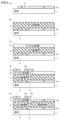
- FIG. FIG. 4 is a cross-sectional view for explaining the method of manufacturing the variable capacitance element according to Embodiment 1;
- 1 is a circuit diagram of a multivalued variable capacitance element according to Embodiment 1.
- FIG. FIG. 10 is a cross-sectional view for explaining the configuration of a variable capacitance element according to a first modified example of the first embodiment;
- FIG. 10 is a cross-sectional view for explaining the configuration of a variable capacitance element according to a second modification of the first embodiment;
- FIG. 10 is a cross-sectional view for explaining the configuration of a variable capacitance element according to a third modified example of the first embodiment
- FIG. 8 is a cross-sectional view for explaining the configuration of a variable capacitance element according to Embodiment 2
- FIG. 10 is a cross-sectional view for explaining the configuration of a variable capacitance element according to a first modified example of the second embodiment
- FIG. 10 is a cross-sectional view for explaining the configuration of a variable capacitance element according to a second modification of the second embodiment
- FIG. 11 is a cross-sectional view for explaining the configuration of a variable capacitance element according to a third modified example of the second embodiment
- FIG. 14 is a cross-sectional view for explaining the configuration of a variable capacitance element according to a fourth modification of the second embodiment
- FIG. 11 is a cross-sectional view for explaining the configuration of a variable capacitance element according to Embodiment 3
- FIG. 11 is a plan view for explaining the configuration of a variable capacitance element according to Embodiment 3
- FIG. 11 is a cross-sectional view for explaining the configuration of a variable capacitance element according to a first modified example of the third embodiment
- FIG. 14 is a cross-sectional view for explaining the configuration of a variable capacitance element according to a second modification of the third embodiment
- FIG. 11 is a cross-sectional view for explaining the configuration of a variable capacitance element according to a fourth modification of the second embodiment
- FIG. 11 is a cross-sectional view for explaining the configuration of a variable capacitance element according to Embodiment 3
- FIG. 11 is a plan view for explaining the configuration of a variable capacitance element
- FIG. 11 is a cross-sectional view for explaining the configuration of a variable capacitance element according to a third modified example of the third embodiment;
- FIG. 11 is a cross-sectional view for explaining the configuration of a variable inductance element according to Embodiment 4;
- FIG. 11 is an equivalent circuit diagram of a variable inductance element according to Embodiment 4;
- FIG. 20 is a plan view for explaining the configuration of a variable inductance element according to a modification of the fourth embodiment;
- FIG. 14 is a cross-sectional view for explaining the configuration of a variable inductance element according to a modification of the fourth embodiment;
- FIG. 11 is a cross-sectional view for explaining the configuration of a variable capacitance element according to Embodiment 5;
- the electronic device capable of varying the physical quantity of a passive device.
- the same reference numerals in the drawings indicate the same or corresponding parts.
- the case where the physical quantity of the passive element is 0 (zero) is not limited to the case where the physical quantity is completely 0 (zero), and the physical quantity is set to 0 (zero) for a certain state of the physical quantity. Any physical quantity less than or equal to a predetermined quantity that can be considered (for example, less than or equal to 1/10,000) may be used.
- the electronic element can be provided with a memory characteristic because it can switch between a state in which the physical quantity of the passive element is present and a state in which the physical quantity is 0 (zero).
- Embodiment 1 a variable capacitive element in which the passive element is a capacitor and the physical quantity to be varied is a capacitance will be described.
- a variable capacitance element capable of switching between a state in which there is capacitance and a state in which the capacitance is 0 (zero) hereinafter also referred to as a state in which there is no capacitance
- FIG. 1 is a cross-sectional view for explaining the configuration of a variable capacitance element 100 according to Embodiment 1.
- FIG. FIG. 2 is a plan view for explaining the configuration of the variable capacitance element 100 according to Embodiment 1.
- FIG. 1 is a cross-sectional view for explaining the configuration of a variable capacitance element 100 according to Embodiment 1.
- FIG. FIG. 2 is a plan view for explaining the configuration of the variable capacitance element 100 according to Embodiment 1.
- FIG. 1 is a cross-sectional view for explaining the configuration of a variable capacitance element 100 according to Em
- a variable capacitance element 100 shown in FIG. 1 includes a switch section 10 forming a field effect transistor formed on a semiconductor substrate 1, and an element section 20 electrically connected to the switch section 10 and forming a capacitor. .
- the element section 20 and the switch section 10 are arranged horizontally with respect to the semiconductor substrate 1 .
- the switch section 10 has a gate electrode 2 , a gate insulating film 3 , a channel forming film 4 , a source electrode 5 and a drain electrode 6 .
- a gate electrode 2 is formed on a semiconductor substrate 1
- a gate insulating film 3 and a channel forming film 4 are sequentially formed over the gate electrode 2, and a source electrode 5 and a drain are formed thereon. They form part of the electrodes 6 respectively.
- the switch section 10 is an oxide FET (Field Effect Transistor).
- LAO lanthanum aluminate
- the gate electrode 2 is formed thereon from platinum (Pt) in a predetermined pattern shown in FIG.
- the gate insulating film 3 for example, a La—HfO 2 film with a thickness of 70 nm is used, and for the channel forming film 4, for example, an IZO film with a thickness of 25 nm is used.
- a source electrode 5 and a drain electrode 6 of platinum (Pt) are formed in a predetermined pattern shown in FIG. 2 on the channel forming film 4 of the IZO film.
- the terminal electrode 5a (first terminal electrode) is provided on the source electrode 5 shown in FIG. 2, the source electrode 5 itself may be used as the terminal electrode 5a.
- the channel width W is 100 ⁇ m and the channel length L is 10 ⁇ m.
- the drain electrode 6 extends not only to the portion formed on the channel forming film 4 but also to the portion forming the element portion 20 .
- the drain electrode 6 includes an electrode 6a forming the switch section 10, an electrode 6c forming the element section 20, and an electrode 6b connecting the electrodes 6a and 6c.
- the electrode 6 a is part of the drain electrode 6 formed on the channel forming film 4 .
- Electrode 6 c is part of drain electrode 6 formed on semiconductor substrate 1 .
- the electrode 6b is part of the drain electrode 6 formed through the gate insulating film 3 .
- the element part 20 is a capacitor provided on a portion of the drain electrode 6 (above the electrode 6c).
- the element portion 20 includes an electrode 6c, a dielectric layer 3a formed of the same insulating film as the gate insulating film 3, and a platinum (Pt) terminal electrode 22 (second terminal electrode) formed over the dielectric layer 3a. including.
- the terminal electrodes 22 are formed in a predetermined pattern shown in FIG. 2, the gate electrode 2 is drawn out from a region where the source electrode 5 and the drain electrode 6 overlap, and a control electrode terminal 2a is provided on the gate electrode 2.
- the element section 20 constitutes a capacitor with the dielectric layer 3a provided between a part of the drain electrode 6 (the electrode 6c) and the terminal electrode 22.
- the capacitor is a portion C1 where the drain electrode 6 and the terminal electrode 22 overlap in plan view, as shown in FIG. Note that the drain electrode 6 is a floating electrode and is not directly electrically connected to the terminal electrode 5a of the variable capacitance element 100 .
- variable capacitance element 100 when the switch section 10 is in the OFF state, a gate voltage equal to or higher than the threshold value is not applied to the gate electrode 2. Therefore, there is an electron depletion layer at the position of the channel forming film 4 overlapping the gate electrode 2 in plan view.
- the source electrode 5 and the drain electrode 6 are not electrically connected. Therefore, in the variable capacitance element 100, a voltage is applied only to the source electrode 5 and no voltage is applied between the electrode 6c and the terminal electrode 22, so that a capacitor is not formed.
- variable capacitance element 100 when the switch section 10 is in the ON state, a channel is formed by applying a gate voltage equal to or higher than the threshold to the gate electrode 2, and the source electrode 5 and the drain electrode 6 are electrically connected. Therefore, in the variable capacitance element 100, a voltage is applied to the source electrode 5 and the drain electrode 6, and a voltage is also applied between the electrode 6c and the terminal electrode 22, thereby forming a capacitor.
- variable capacitive element 100 by turning on/off the switch section 10, the state without the capacitor and the state with the capacitor are switched to turn the capacitor on/off.
- the variable capacitive element 100 includes a switch portion 10 that is turned ON/OFF by a voltage applied to the gate electrode 2 (control electrode terminal 2a), and a part of the drain electrode 6 (electrode 6c) and the element portion 20 operated by the terminal 22a of the terminal electrode 22 (second terminal electrode), and operated by three terminals.
- variable capacitance element 100 the gate electrode 2 (control electrode terminal 2a) of the switch section 10 and the terminal 22a of the terminal electrode 22 (second terminal electrode) of the element section 20 are electrically separated.
- the operation of the switch section 10 is not affected by the signal on the element section 20 side.
- a terminal electrode 5a (first terminal electrode) and a terminal 22a of a terminal electrode 22 (second terminal electrode) of the variable capacitance element 100 are connected to a filter circuit or the like, while a control electrode terminal 2a for switching presence/absence of capacitance is connected to the terminal electrode 22a. It is connected to a circuit separate from the filter circuit. Therefore, the signal applied to the control electrode terminal 2a is less likely to be affected by the signal of the filter circuit.
- variable capacitance element 100 the electrical resistance of the channel forming film 4 between the source electrode 5 and the drain electrode 6 can be lowered by shortening the channel length L of the switch section 10. Therefore, in the variable capacitance element 100, the switching speed (time constant) of the switch section 10 can be improved in order to switch between the presence and absence of the capacitance at high speed.
- FIG. 3A a portion of the gate electrode 2 and the drain electrode 6 (electrode 6c) of platinum (Pt) having a film thickness of 80 nm is formed on the (100) plane of the semiconductor substrate 1 of prepared lanthanum aluminate (LAO). ).
- the gate electrode 2 is formed by forming a photoresist in a predetermined pattern on the (100) plane of the semiconductor substrate 1 using a photolithography technique, and then depositing platinum (Pt) by radio frequency (RF) sputtering. are formed by removing the photoresist by lift-off.
- RF radio frequency
- a gate insulating film 3 having a thickness of 70 nm is formed on the surface of the semiconductor substrate 1 on which the gate electrode 2 and part of the drain electrode 6 (electrode 6c) are formed.
- the gate insulating film 3 is formed by spin-coating a La—HfO 2 solution on the surface of the semiconductor substrate 1 on which the gate electrode 2 is formed using a chemical solution deposition (CSD) method. C. and then fired at 800.degree. C. in an oxygen atmosphere to crystallize.
- CSD chemical solution deposition
- a channel forming film 4 with a film thickness of 25 nm is formed overlying the gate insulating film 3 .
- the channel forming film 4 is formed by spin-coating an IZO solution over the gate insulating film 3 using a chemical solution deposition method (CSD), dried at 150° C., and then under an oxygen atmosphere. It is formed by firing at 500° C. to crystallize it.
- CSD chemical solution deposition method
- the electrode 6b is, for example, a via conductor formed by forming a hole penetrating the gate insulating film 3 and the channel forming film 4 at a position overlapping with the electrode 6c and filling the formed hole with a conductive material.
- the electrode 6b is, for example, a via conductor formed by forming a hole penetrating the gate insulating film 3 and the channel forming film 4 at a position overlapping with the electrode 6c and filling the formed hole with a conductive material.
- FIG. 3D on the channel forming film 4, a part of the source electrode 5 and the drain electrode 6 (electrode 6c) of platinum (Pt) with a film thickness of 80 nm is formed.
- the source electrode 5 and the electrode 6c are formed by forming a photoresist with a predetermined pattern on the channel forming film 4 using a photolithography technique, and then depositing platinum (Pt) by radio frequency (RF) sputtering. Then, the photoresist is removed by lift-off.
- the electrodes 6c and 6b are electrically connected.
- the channel forming film 4 on a portion of the drain electrode 6 is removed to form a platinum (Pt) terminal electrode 22 with a film thickness of 80 nm.
- the terminal electrode 22 is formed by removing the channel forming film 4, forming a photoresist in a predetermined pattern on the dielectric layer 3a using a photolithography technique, and then applying platinum by radio frequency (RF) sputtering. It is formed by depositing (Pt) and removing the photoresist by lift-off.
- RF radio frequency
- variable capacitive element 100 described so far has been described as an element capable of switching between a state without a capacitor and a state with a capacitor. However, by forming a plurality of variable capacitance elements 100 in a matrix on the semiconductor substrate 1, a multivalued variable capacitance element can be configured.
- FIG. 4 is a circuit diagram of the multi-value variable capacitance element 100a according to the first embodiment.
- FIG. 4 shows a circuit diagram of a variable capacitive element 100a in which n ⁇ n pieces of one variable capacitive element 100 shown in FIG. 1 are connected in a matrix.
- the terminal electrode 5 a first terminal electrode
- the terminal electrode 22 second terminal electrode
- the control electrode terminals 2a of the n ⁇ n variable capacitance elements 100 are provided separately, and are shown as terminals G11 to Gnn in FIG.
- the variable capacitance element 100 includes the switch section 10 that constitutes a field effect transistor, and the element section 20 that is electrically connected to the switch section 10 and constitutes a capacitor.
- the switch part 10 is formed by overlapping the source electrode 5 , the drain electrode 6 , the channel forming film 4 overlapping at least part of the source electrode 5 and part of the drain electrode 6 , and the channel forming film 4 . and a gate electrode 2 formed over the gate insulating film 3 .
- a capacitor is formed between a terminal electrode 5a (first terminal electrode) electrically connected to the source electrode 5 and a portion of the drain electrode 6 (electrode 6c) with the dielectric layer 3a interposed therebetween. and a terminal electrode 22 (second terminal electrode).
- Dielectric layer 3a and gate insulating film 3 are the same insulating film.
- variable capacitance element 100 As a result, in the variable capacitance element 100 according to the first embodiment, a part of the drain electrode 6 (electrode 6c) and the terminal electrode 22 are connected with the dielectric layer 3a formed of the same insulating film as the gate insulating film 3 interposed therebetween. Since a capacitor is formed between them, the capacitance can be varied in a wide range including the case where the capacitance becomes 0 (zero).
- variable capacitance element 100 the number of processes can be reduced by forming the dielectric layer 3a and the gate insulating film 3 from the same insulating film. Further, the variable capacitance element 100 is formed by forming the switch section 10 and the element section 20 in the horizontal direction with respect to the semiconductor substrate 1 without forming the element section 20 overlapping the switch section 10, so that high-temperature processing or the like can be performed.
- the dielectric layer 3a a dielectric material that requires a process that adversely affects the switch section 10 or a dielectric material that is affected by the orientation of the underlying layer can be selected for the dielectric layer 3a, improving the selectivity of the material.
- part of the drain electrode 6 is formed on the surface of the dielectric layer 3a on the same side as the surface of the gate insulating film 3 on which the gate electrode 2 is formed, and the terminal electrode 22 is formed on the same surface of the dielectric layer 3a. , are formed on the surface of the dielectric layer 3a opposite to the surface of the gate insulating film 3 on which the gate electrode 2 is formed.
- FIG. 5 is a cross-sectional view for explaining the configuration of a variable capacitance element 100A according to the first modification of the first embodiment.
- variable capacitive element 100A shown in FIG. 5 the same configurations as those of variable capacitive element 100 shown in FIG. 1 are denoted by the same reference numerals, and detailed description thereof will not be repeated.
- a variable capacitance element 100A shown in FIG. 5 includes a switch section 10 forming a field effect transistor formed on a semiconductor substrate 1, and an element section 20A electrically connected to the switch section 10 and forming a passive element.
- a dielectric layer 3a provided between a portion of the drain electrode 6 (electrode 6c) and the terminal electrode 22 constitutes a capacitor
- the terminal electrode 22 and a portion of the drain electrode 6 (electrode 6c) constitute a capacitor
- 6d) constitutes a capacitor.
- the dielectric layer sandwiched between a portion of the drain electrode 6 (electrodes 6c and 6d) and the terminal electrode 22 includes a dielectric layer 3a (first dielectric layer) made of the same insulating film as the gate insulating film 3, and a gate insulating film 3a. and a dielectric layer 7 (second dielectric layer) formed of an insulating film different from the insulating film 3 .
- the element portion 20A includes a portion of the drain electrode 6 (electrode 6c), a dielectric layer 3a (first dielectric layer), a terminal electrode 22, a dielectric layer 7 (second dielectric layer), and a drain electrode. 6 (electrode 6d) are sequentially stacked to form a multi-layered capacitor.
- the dielectric layer 3a and the dielectric layer 7 may have the same film thickness or different film thicknesses. Furthermore, dielectric layer 3a and dielectric layer 7 may be made of the same dielectric material or may be made of different dielectric materials. Specifically, either the dielectric layer 3a or the dielectric layer 7 may be made of a dielectric material whose dielectric constant depends on the DC bias voltage (for example, (Ba, Sr) TiO3-based perovskite oxide, etc.). . By using the dielectric material for either the dielectric layer 3a or the dielectric layer 7, the capacitance C ON when the switch section 10 is turned on can be finely adjusted.
- DC bias voltage for example, (Ba, Sr) TiO3-based perovskite oxide, etc.
- variable capacitance element 100A when the dielectric material is used for the dielectric layer 7 and a DC bias voltage (V DC ) is applied to the terminal electrode 22, the variable capacitance element 100A has a capacitance C ON when the switch section 10 is turned ON.
- C ON C A +C B (V DC ). Since C B (V DC ) varies depending on the DC bias voltage (V DC ) applied to the terminal electrode 22, it is possible to finely adjust the capacitance C ON .
- variable capacitance element 100A in the element portion 20A, part of the drain electrode 6 (electrode 6c), the dielectric layer 3a (first dielectric layer), the terminal electrode 22, and the dielectric layer 7 (second dielectric layer) and part of the drain electrode 6 (electrode 6d) are laminated in this order to form a two-layer capacitor, but a capacitor with three or more layers may also be formed.
- FIG. 6 is a cross-sectional view for explaining the configuration of a variable capacitance element 100B according to the second modification of the first embodiment.
- variable capacitive element 100B shown in FIG. 6 the same configurations as those of variable capacitive element 100A shown in FIG. 5 are denoted by the same reference numerals, and detailed description thereof will not be repeated.
- a variable capacitance element 100B shown in FIG. 6 includes a switch section 10A that constitutes a field effect transistor formed on a semiconductor substrate 1, and an element section 20A that is electrically connected to the switch section 10A and constitutes a passive element.
- the switch section 10A has a gate electrode 2, a gate insulating film 3, a channel forming film 4, a source electrode 5, a drain electrode 6, and a passivation film 7a.
- a gate electrode 2 is formed on a semiconductor substrate 1, a gate insulating film 3 and a channel forming film 4 are sequentially formed over the gate electrode 2, and a source electrode 5 and a drain are formed thereon.
- a part of each electrode 6 is formed and covered with a passivation film 7a.
- a passivation film 7a is formed covering the channel forming film 4 between the source electrode 5 and the drain electrode 6 with a part of the dielectric layer 7. As shown in FIG.
- the passivation film 7 a can suppress deterioration of the characteristics of the switch section 10 . Further, by forming the passivation film 7a on a part of the dielectric layer 7, the passivation film can be formed so as to cover the channel forming film 4 without adding a separate process.
- FIG. 7 is a cross-sectional view for explaining the configuration of a variable capacitance element 100C according to the third modification of the first embodiment.
- variable capacitive element 100C shown in FIG. 7 the same configurations as variable capacitive element 100A shown in FIG. 5 are denoted by the same reference numerals, and detailed description thereof will not be repeated.
- a variable capacitance element 100C shown in FIG. 7 includes a switch section 10B forming a field effect transistor formed on a semiconductor substrate 1, and an element section 20B electrically connected to the switch section 10B and forming a passive element.
- the switch section 10B has a gate electrode 2, a gate insulating film 3, a channel forming film 4, a source electrode 5 and a drain electrode 6.
- the switch section 10B employs a top gate structure instead of a bottom gate structure like the switch section 10 shown in FIG.
- a channel forming film 4 is superimposed on the dielectric layer 7
- a source electrode 5 and a drain electrode 6 are formed on the channel forming film 4
- a gate insulating film 3 is formed on the source electrode 5 and the drain electrode 6.
- a gate electrode 2 is formed on the gate insulating film 3 .
- a part of the drain electrode 6 (the electrode 6d) is formed on the semiconductor substrate 1 side. ), a terminal electrode 22, a dielectric layer 3a (first dielectric layer), and a portion of the drain electrode 6 (electrode 6c) are sequentially laminated to form a two-layer capacitor.
- variable capacitive element 100C employs the switch section 10B with the top gate structure, the same effect as the variable capacitive element 100A that employs the switch section 10 with the bottom gate structure can be obtained. Further, a switch part having a top-gate structure may be adopted as the switch part of the variable capacitance element 100 shown in FIG.
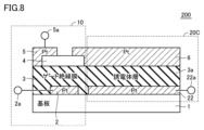
- FIG. 8 is a cross-sectional view for explaining the configuration of the variable capacitance element 200 according to the second embodiment.
- variable capacitive element 200 shown in FIG. 8 the same configurations as those of variable capacitive element 100 shown in FIG. 1 are denoted by the same reference numerals, and detailed description thereof will not be repeated.
- a variable capacitance element 200 shown in FIG. 8 includes a switch section 10 that constitutes a field effect transistor, and an element section 20C that is electrically connected to the switch section 10 and constitutes a passive element.
- the element section 20 ⁇ /b>C and the switch section 10 are arranged horizontally with respect to the semiconductor substrate 1 .
- the switch section 10 has a gate electrode 2 , a gate insulating film 3 , a channel forming film 4 , a source electrode 5 and a drain electrode 6 .
- a gate electrode 2 is formed on a semiconductor substrate 1
- a gate insulating film 3 and a channel forming film 4 are sequentially formed over the gate electrode 2, and a source electrode 5 and a drain are formed thereon. They form part of the electrodes 6 respectively.
- the drain electrode 6 extends not only to the portion formed on the channel forming film 4, but also to the portion forming the element portion 20C.
- the element portion 20C is a capacitor provided on a part of the drain electrode 6.
- the element portion 20C includes a portion of the drain electrode 6, a dielectric layer 3a formed of the same insulating film as the gate insulating film 3, and a platinum (Pt) terminal electrode 22 (second electrode) formed over the dielectric layer 3a. two terminal electrodes).
- the drain electrode 6 is a floating electrode and is not directly electrically connected to the terminal electrode 5a of the variable capacitance element 200. As shown in FIG.
- variable capacitance element 200 when the switch section 10 is in the OFF state, a gate voltage equal to or higher than the threshold value is not applied to the gate electrode 2. Therefore, there is an electron depletion layer at the position of the channel forming film 4 overlapping the gate electrode 2 in plan view.
- the source electrode 5 and the drain electrode 6 are not electrically connected. Therefore, in the variable capacitance element 200, a voltage is applied only to the source electrode 5 and no voltage is applied between the electrode 6c and the terminal electrode 22, so that a capacitor is not formed.
- variable capacitance element 200 when the switch section 10 is in the ON state, a channel is formed by applying a gate voltage equal to or higher than the threshold to the gate electrode 2, and the source electrode 5 and the drain electrode 6 are electrically connected. Therefore, in the variable capacitance element 200, a voltage is applied to the source electrode 5 and the drain electrode 6, and a voltage is also applied between the electrode 6c and the terminal electrode 22, thereby forming a capacitor.
- variable capacitive element 200 by turning the switch section 10 ON/OFF, the capacitor is switched between the state without the capacitor and the state with the capacitor, thereby turning the capacitor ON/OFF.
- the variable capacitance element 200 includes a switch section 10 which is turned on/off by a voltage applied to the gate electrode 2 (control electrode terminal 2a), and a portion of the drain electrode 6 and a terminal through a terminal electrode 5a (first terminal electrode). It is divided into a terminal 22a of the electrode 22 (second terminal electrode) and an element portion 20C that operates with three terminals.
- the terminal electrode 22 is formed on the surface of the dielectric layer 3a on the same side as the surface of the gate insulating film 3 on which the gate electrode 2 is formed.
- a part of the drain electrode 6 is formed on the surface of the dielectric layer 3a opposite to the surface of the gate insulating film 3 on which the gate electrode 2 is formed.
- variable capacitance element 200 in the variable capacitance element 200 according to the first embodiment, a capacitor is formed between a part of the drain electrode 6 and the terminal electrode 22 with the dielectric layer 3a formed of the same insulating film as the gate insulating film 3 interposed therebetween. Since it is configured, the capacitance can be varied in a wide range including the case where the capacitance becomes 0 (zero).
- FIG. 9 is a cross-sectional view for explaining the configuration of a variable capacitance element 200A according to the first modification of the second embodiment.
- variable capacitive element 200A shown in FIG. 9 the same configurations as those of variable capacitive element 200 shown in FIG. 8 are denoted by the same reference numerals, and detailed description thereof will not be repeated.
- a variable capacitance element 200A shown in FIG. 9 includes a switch section 10 forming a field effect transistor formed on a semiconductor substrate 1, and an element section 20D electrically connected to the switch section 10 and forming a passive element.
- a dielectric layer 3a provided between a portion of the drain electrode 6 and a portion of the terminal electrode 22 (terminal electrode 221) constitutes a capacitor.
- the dielectric layer 7 provided between the electrode 22 and part of the electrode 22 (the terminal electrode 222) constitutes a capacitor.
- the terminal electrode 22 includes a terminal electrode 221 formed on the semiconductor substrate 1, a terminal electrode 222 formed on the dielectric layer 7, and a terminal electrode 223 connecting the terminal electrode 221 and the terminal electrode 222. include.
- a dielectric layer sandwiched between part of the drain electrode 6 and part of the terminal electrode 22 (terminal electrodes 221 and 222) is a dielectric layer 3a (first dielectric layer 3a) made of the same insulating film as the gate insulating film 3. ) and a dielectric layer 7 (second dielectric layer) formed of an insulating film different from the gate insulating film 3 .
- the element portion 20D includes a portion of the terminal electrode 22 (terminal electrode 221), a dielectric layer 3a (first dielectric layer), a drain electrode 6, a dielectric layer 7 (second dielectric layer), a terminal A part of the electrode 22 (terminal electrode 222) is laminated in order to form a multi-layered capacitor.
- the variable capacitance element 200A including the element section 20D can further increase the capacity of the capacitor.
- the dielectric layer 3a and the dielectric layer 7 may have the same film thickness or different film thicknesses.
- dielectric layer 3a and dielectric layer 7 may be made of the same dielectric material or may be made of different dielectric materials.
- variable capacitance element 200A in the element portion 20D, part of the terminal electrode 22 (terminal electrode 221), the dielectric layer 3a (first dielectric layer), the drain electrode 6, and the dielectric layer 7 (second dielectric (body layer) and a portion of the terminal electrode 22 (terminal electrode 222) are laminated in order to form a two-layer capacitor, but a capacitor with three or more layers may also be formed.
- FIG. 10 is a cross-sectional view for explaining the configuration of a variable capacitance element 200B according to the second modification of the second embodiment.
- variable capacitive element 200B shown in FIG. 10 the same configurations as variable capacitive element 200A shown in FIG. 9 are denoted by the same reference numerals, and detailed description thereof will not be repeated.
- a variable capacitance element 200B shown in FIG. 10 includes a switch section 10A that constitutes a field effect transistor formed on a semiconductor substrate 1, and an element section 20D that is electrically connected to the switch section 10A and constitutes a passive element.
- the switch section 10A has a gate electrode 2, a gate insulating film 3, a channel forming film 4, a source electrode 5, a drain electrode 6, and a passivation film 7a.
- a gate electrode 2 is formed on a semiconductor substrate 1, a gate insulating film 3 and a channel forming film 4 are sequentially formed over the gate electrode 2, and a source electrode 5 and a drain are formed thereon.
- a part of each electrode 6 is formed and covered with a passivation film 7a.
- a passivation film 7a is formed covering the channel forming film 4 between the source electrode 5 and the drain electrode 6 with a part of the dielectric layer 7.
- the passivation film 7a can suppress deterioration of the characteristics of the switch section 10A. Further, by forming the passivation film 7a on a part of the dielectric layer 7, the passivation film can be formed so as to cover the channel forming film 4 without adding a separate process.
- FIG. 11 is a cross-sectional view for explaining the configuration of a variable capacitance element 200C according to the third modification of the second embodiment.
- variable capacitive element 200C shown in FIG. 11 the same configurations as variable capacitive element 200A shown in FIG. 9 are denoted by the same reference numerals, and detailed description thereof will not be repeated.
- a variable capacitance element 100C shown in FIG. 11 includes a switch section 10B forming a field effect transistor formed on a semiconductor substrate 1, and an element section 20E electrically connected to the switch section 10B and forming a passive element.
- the switch section 10B has a gate electrode 2, a gate insulating film 3, a channel forming film 4, a source electrode 5 and a drain electrode 6.
- the switch section 10B employs a top gate structure instead of a bottom gate structure like the switch section 10 shown in FIG.
- a channel forming film 4 is superimposed on the dielectric layer 7
- a source electrode 5 and a drain electrode 6 are formed on the channel forming film 4
- a gate insulating film 3 is formed on the source electrode 5 and the drain electrode 6.
- a gate electrode 2 is formed on the gate insulating film 3 .
- the element portion 20E includes a portion of the terminal electrode 22 (terminal electrode 222), the dielectric layer 7 (second dielectric layer), the drain electrode 6, and the dielectric layer 3a (first dielectric layer). , and part of the terminal electrode 22 (terminal electrode 221) are stacked in order to form a two-layer capacitor.
- variable capacitive element 200C employs the switch section 10B with the top gate structure, the same effect as the variable capacitive element 200A that employs the switch section 10 with the bottom gate structure can be obtained. Further, a switch part having a top-gate structure may be adopted as the switch part of the variable capacitance element 200 shown in FIG.
- FIG. 12 is a cross-sectional view for explaining the configuration of a variable capacitance element 200D according to the fourth modification of the second embodiment.
- variable capacitive element 200D shown in FIG. 12 the same configurations as those of variable capacitive element 200 shown in FIG. 8 are denoted by the same reference numerals, and detailed description thereof will not be repeated.
- a variable capacitance element 100D shown in FIG. 12 includes a switch section 10C forming a field effect transistor formed on a semiconductor substrate 1, and an element section 20C electrically connected to the switch section 10C and forming a passive element.
- the switch section 10C has a gate electrode 2, a gate insulating film 3, a channel forming film 4, a source electrode 5 and a drain electrode 6. However, the switch section 10C does not have a top contact structure in which the channel forming film 4 is formed below the source electrode 5 and the drain electrode 6 as in the switch section 10 shown in FIG. This is a bottom contact structure in which a channel forming film 4 is formed on the upper side of the .
- the bottom contact structure is a structure in which the source electrode 5 and the drain electrode 6 are contacted under the channel forming film 4 .
- variable capacitive element 200D employs the switch section 10C with the bottom contact structure, the same effect as the variable capacitive element 200A that employs the switch section 10 with the top contact structure can be obtained.
- a switch part having a bottom contact structure may be adopted as the switch part of the variable capacitance element 100 shown in FIG.
- variable capacitance element 200 switches between a state without a capacitor and a state with a capacitor by turning on/off the switch section 10 to turn the capacitor on/off.
- the state is switched between a state in which the capacitance of the capacitor is small and a state in which the capacitance of the capacitor is large.
- FIG. 13 is a cross-sectional view for explaining the configuration of the variable capacitance element 300 according to the third embodiment.
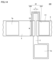
- FIG. 14 is a plan view for explaining the configuration of variable capacitance element 300 according to the third embodiment.
- variable capacitive element 300 shown in FIGS. 13 and 14 the same configurations as those of variable capacitive element 200 shown in FIG. 8 are denoted by the same reference numerals, and detailed description thereof will not be repeated.
- a variable capacitance element 300 shown in FIG. 13 includes a switch section 10 forming a field effect transistor formed on a semiconductor substrate 1, and an element section 20FA electrically connected to the switch section 10 and forming a passive element. there is The element section 20FA and the switch section 10 are arranged horizontally with respect to the semiconductor substrate 1 .
- the element section 20FA includes a dielectric layer 3a and a terminal electrode 22 (second terminal electrode) formed over the dielectric layer 3a.
- the terminal electrode 22 is formed in a pattern avoiding the channel region formed between the source electrode 5 and the drain electrode 6, as shown in FIG. Therefore, in the cross-sectional view shown in FIG. 13, the terminal electrode 22 is provided not only on the terminal electrode 22A formed below the drain electrode 6, but also on the terminal electrode 22B formed below the source electrode 5.
- the element part 20FA forms a first capacitor between the drain electrode 6 and the terminal electrode 22A, and forms a second capacitor between the source electrode 5 and the terminal electrode 22B.
- the first capacitor is a portion C1 where the drain electrode 6 and the terminal electrode 22A overlap in plan view as shown in FIG.
- the second capacitor is a portion C2 where the source electrode 5 and the terminal electrode 22B overlap in plan view.
- variable capacitance element 300 when the switch section 10 is in the OFF state, a gate voltage equal to or higher than the threshold value is not applied to the gate electrode 2. Therefore, there is an electron depletion layer at the position of the channel forming film 4 overlapping the gate electrode 2 in plan view. The source electrode 5 and the drain electrode 6 are not electrically connected. Therefore, since the voltage is applied only between the source electrode 5 and the portion of the terminal electrode 22B facing the source electrode 5, the variable capacitance element 300 has the capacity of only the second capacitor.
- variable capacitance element 300 when the switch section 10 is in the ON state, a channel is formed by applying a gate voltage equal to or higher than the threshold to the gate electrode 2, and the source electrode 5 and the drain electrode 6 are electrically connected. Therefore, the variable capacitance element 300 has a combined capacitance of the first capacitor and the second capacitor because a voltage is applied between the source electrode 5 and the drain electrode 6 and the facing terminal electrode 22 .
- terminal electrode 22 is not formed in a pattern that circumvents the entire channel region formed between the source electrode 5 and the drain electrode 6 as shown in FIG. A pattern that overlaps a part of the region may also be used.
- variable capacitance element 300 a portion of the terminal electrode 22 (terminal electrode 22B) faces a portion of the source electrode 5 with the dielectric layer 3a interposed therebetween. Accordingly, the variable capacitance element 300 can switch the state of the element section 20FA between the state of the second capacitor and the state of the first capacitor+second capacitor by turning the switch section 10 ON/OFF.
- FIG. 15 is a cross-sectional view for explaining the configuration of a variable capacitance element 300A according to the first modification of the third embodiment.
- variable capacitive element 300A shown in FIG. 15 the same configurations as those of variable capacitive element 300 shown in FIG. 15 are denoted by the same reference numerals, and detailed description thereof will not be repeated.
- a variable capacitance element 300A shown in FIG. 15 includes a switch section 10A forming a field effect transistor formed on a semiconductor substrate 1, and an element section 20F electrically connected to the switch section 10A and forming a passive element.
- the first capacitor of the element portion 20F includes a capacitor formed of the dielectric layer 3a provided between part of the drain electrode 6 and part of the terminal electrode 22 (terminal electrode 22A), and a capacitor composed of the dielectric layer 7 provided between the terminal electrode 22 and a portion of the terminal electrode 22 (terminal electrode 22C).
- the terminal electrode 22 includes a terminal electrode 22A formed on the semiconductor substrate 1, a terminal electrode 22C formed on the dielectric layer 7, and a terminal electrode 22D connecting the terminal electrode 22A and the terminal electrode 22C. include.
- a dielectric layer sandwiched between part of the drain electrode 6 and part of the terminal electrode 22 (terminal electrodes 22A and 22C) is a dielectric layer 3a (first dielectric layer 3a) made of the same insulating film as the gate insulating film 3. ) and a dielectric layer 7 (second dielectric layer) formed of an insulating film different from the gate insulating film 3 .
- the first capacitor of the element section 20F includes part of the terminal electrode 22 (terminal electrode 22A), dielectric layer 3a (first dielectric layer), drain electrode 6, dielectric layer 7 (second dielectric layer ) and part of the terminal electrode 22 (terminal electrode 22C) are stacked in order to form a multi-layer capacitor.
- the variable capacitance element 300A including the element section 20F can further increase the capacitance of the capacitor.
- the dielectric layer 3a and the dielectric layer 7 may have the same film thickness or different film thicknesses.
- dielectric layer 3a and dielectric layer 7 may be made of the same dielectric material or may be made of different dielectric materials.
- variable capacitance element 300A in the first capacitor of the element section 20F, part of the terminal electrode 22 (terminal electrode 22A), the dielectric layer 3a (first dielectric layer), the drain electrode 6, the dielectric layer 7 (the second dielectric layer) and part of the terminal electrode 22 (the terminal electrode 22C) are laminated in this order to form a two-layer capacitor, but a three-layer or more capacitor may be formed.
- FIG. 16 is a cross-sectional view for explaining the configuration of a variable capacitance element 300B according to the second modification of the third embodiment.
- variable capacitive element 300B shown in FIG. 16 the same configurations as those of variable capacitive element 300A shown in FIG. 15 are denoted by the same reference numerals, and detailed description thereof will not be repeated.
- a variable capacitance element 300B shown in FIG. 16 includes a switch section 10A forming a field effect transistor formed on a semiconductor substrate 1, and an element section 20G electrically connected to the switch section 10A and forming a passive element.
- the second capacitor of the element section 20G is not a capacitor formed of the dielectric layer 3a provided between the source electrode 5 and a portion of the terminal electrode 22 (terminal electrode 22B), but is formed by the source electrode 5 and the terminal electrode 22B. (terminal electrode 22E).
- the dielectric layer 7 formed on the drain electrode 6 is extended over the source electrode 5, and a terminal electrode 22E is formed at a position overlapping the source electrode 5 in plan view.
- terminal electrode 22E part of the terminal electrode 22 (terminal electrode 22E) faces part of the source electrode 5 with the dielectric layer 7 interposed therebetween.
- the terminal electrode 22E bypasses the channel region and is electrically connected to the terminal electrode 22C.
- the dielectric layer 7 constitutes a passivation film 7 a covering the channel forming film 4 between the source electrode 5 and the drain electrode 6 .
- the second capacitor of the element section 20G may further be provided with a terminal electrode 22B.
- the second capacitor of the element portion 20G consists of part of the terminal electrode 22 (terminal electrode 22B), dielectric layer 3a (first dielectric layer), and part of the source electrode 5. , the dielectric layer 7 (second dielectric layer) and a portion of the terminal electrode 22 (terminal electrode 22E) are sequentially laminated to form a two-layer capacitor.
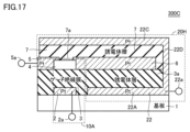
- FIG. 17 is a cross-sectional view for explaining the configuration of a variable capacitance element 300C according to the third modification of the third embodiment.
- variable capacitive element 300C shown in FIG. 17 the same configurations as variable capacitive element 300A shown in FIG. 15 are denoted by the same reference numerals, and detailed description thereof will not be repeated.
- a variable capacitance element 300C shown in FIG. 17 includes a switch section 10A forming a field effect transistor formed on a semiconductor substrate 1, and an element section 20H electrically connected to the switch section 10A and forming a passive element.
- the element portion 20H is formed by extending the dielectric layer 7 formed on the drain electrode 6 to the source electrode 5 and further extending the terminal electrode 22C to the source electrode 5.
- a terminal electrode 22B may be further provided in the element section 20H.
- the second capacitor of the element portion 20H consists of part of the terminal electrode 22 (terminal electrode 22B), dielectric layer 3a (first dielectric layer), and part of the source electrode 5. , a dielectric layer 7 (second dielectric layer) and a portion of the terminal electrode 22 (a portion of the terminal electrode 22C) are sequentially laminated to form a two-layer capacitor.
- FIG. 18 is a cross-sectional view for explaining the configuration of variable inductance element 400 according to the fourth embodiment.
- FIG. 19 is an equivalent circuit diagram of variable inductance element 400 according to the fourth embodiment.
- variable inductance element 400 shown in FIGS. 18 and 19 the same configurations as those of variable capacitance element 100 shown in FIG. 1 are denoted by the same reference numerals, and detailed description thereof will not be repeated.
- the same materials as those of the variable capacitance element 100 can be used for the same configuration.
- a variable inductance element 400 shown in FIG. 18 includes a switch section 10 that constitutes a field effect transistor, and an element section 40 that is electrically connected to the switch section 10 and constitutes a passive element.
- the element section 40 is provided on the right side of the switch section 10 in the drawing.
- the switch section 10 has a gate electrode 2 , a gate insulating film 3 , a channel forming film 4 , a source electrode 5 and a drain electrode 6 .
- a gate electrode 2 is formed on a semiconductor substrate 1
- a gate insulating film 3 and a channel forming film 4 are sequentially formed over the gate electrode 2, and a source electrode 5 and a drain are formed thereon. They form part of the electrodes 6 respectively.
- the element portion 40 is an inductor, and one end of the coil electrode 41 is electrically connected to part of the drain electrode 6 (upper portion of the electrode 6c).
- the coil electrode 41 is formed by stacking it in the dielectric layer 3a made of the same insulating film as the gate insulating film 3, and the other end is electrically connected to the terminal 22a. That is, the element portion 4A has an inductor (coil electrode 41) between the terminal electrode 5a (first terminal electrode) electrically connected to the source electrode 5 and a part of the drain electrode 6 with the dielectric layer 3a interposed therebetween. ) and a terminal 22a (second terminal electrode).
- the switch section 10 is the first inductor L1
- the element section 40 is the second inductor L2. Since the first inductor L1 does not include a coil electrode, it has an inductance of a predetermined amount or less (for example, 1/10,000 or less) that can be regarded as 0 (zero). On the other hand, since the second inductor L2 includes the coil electrode 41, it has an inductance due to the coil electrode 41. As shown in FIG.
- variable inductance element 400 similarly to the variable capacitance element 100, when the switch section 10 is in the OFF state, a gate voltage equal to or higher than the threshold value is not applied to the gate electrode 2, so that the channel formation film 4 overlapping the gate electrode 2 in plan view. There is an electron depletion layer at the position, and the source electrode 5 and the drain electrode 6 are not electrically connected. Therefore, the variable inductance element 400 becomes the inductance of only the first inductor L1.
- variable inductance element 400 when the switch section 10 is in the ON state, a channel is formed by applying a gate voltage equal to or higher than the threshold to the gate electrode 2, and the source electrode 5 and the drain electrode 6 are electrically connected. Therefore, the variable inductance element 400 becomes the inductance of the second inductor L2 because the current flows through the coil electrode 41 between the drain electrode 6 and the terminal 22a.
- variable inductance element 400 by turning on/off the switch section 10, the state without the inductor and the state with the inductor are switched to turn the inductor on/off.
- the variable inductance element 400 includes a switch section 10 that is turned ON/OFF by a voltage applied to the gate electrode 2 (control electrode terminal 2a), and a portion of the drain electrode 6 (electrode 6c) and an element portion 40 that operates with the terminal 22a of the terminal electrode 22 (second terminal electrode), and operates with three terminals.
- variable inductance element 400 has a terminal electrode 5a (first terminal electrode) and a terminal 22a (second terminal electrode) connected to a converter circuit or the like.
- a control electrode terminal 2a for varying the inductance is connected to a circuit different from the converter circuit. Therefore, the signal applied to the control electrode terminal 2a is less likely to be affected by the signal of the converter circuit.
- the terminal electrode 5a (first terminal electrode) and the terminal 22a (second terminal electrode) are electrically connected by wiring. You may
- variable inductance element 400 As shown in FIG. 18, the second inductor L2 is formed by laminating the coil electrode 41 within the dielectric layer 3a.
- FIG. 20 is a plan view for explaining the configuration of a variable inductance element 400A according to a modification of the fourth embodiment.
- FIG. 21 is a cross-sectional view for explaining the configuration of a variable inductance element 400A according to a modification of the fourth embodiment.
- variable inductance element 400A shown in FIGS. 20 and 21 the same configurations as those of variable capacitance element 100 shown in FIG. 1 and variable inductance element 400 shown in FIG. 18 are denoted by the same reference numerals, and detailed description thereof will not be repeated.
- the same material as the variable capacitance element 100 can be used for the same configuration.
- the element portion 40A is an inductor, and one end of the coil electrode 42 is electrically connected to the drain electrode 6.
- the coil electrode 42 is planarly formed on the dielectric layer 3a made of the same insulating film as the gate insulating film 3, and the other end is electrically connected to the terminal 22a. That is, the element portion 40A includes an inductor (coil electrode 42) between the terminal electrode 5a (first terminal electrode) electrically connected to the source electrode 5 and a portion of the drain electrode 6 in contact with the dielectric layer 3a. ) and a terminal 22a (second terminal electrode).
- the switch section 10 is the first inductor L1
- the element section 40A is the second inductor L2. Since the second inductor L2 includes the coil electrode 42, it has an inductance due to the coil electrode 42. As shown in FIG.
- variable inductance elements 400 and 400A include the switch section 10 that constitutes a field effect transistor, and the element sections 40 and 40A that are electrically connected to the switch section 10 and constitute inductors. , is equipped with The switch part 10 is formed by overlapping the source electrode 5 , the drain electrode 6 , the channel forming film 4 overlapping at least part of the source electrode 5 and part of the drain electrode 6 , and the channel forming film 4 . and a gate electrode 2 formed over the gate insulating film 3 .
- the element portions 40 and 40A include a terminal electrode 5a (first terminal electrode) electrically connected to the source electrode 5 and a terminal 22a (second terminal electrode) that constitutes an inductor by the coil electrodes 41 and 42 between the drain electrode 6 and the drain electrode 6. terminal electrodes).
- variable inductance elements 400 and 400A according to the fourth embodiment form an inductor between the drain electrode 6 and the terminal 22a. can do.
- a multi-valued variable inductance element may be configured by forming a plurality of variable inductance elements 400 and 400A in a matrix. Also, by changing the coil electrode 41 shown in FIG. 18 to a resistance element, the passive element may be used as a variable resistor element. Furthermore, the configuration of the switch section 10 may be, for example, a silicon MOSFET, a GaNFET, or the like.
- variable inductance element 400 a capacitor is formed by sandwiching a dielectric layer between a part of the drain electrode (the electrode 6c) and the second terminal electrode (the terminal electrode 22) of the variable capacitance element 100 shown in FIG. Instead, an inductor composed of a coil electrode 41 connecting a part of the drain electrode (electrode 6c) and the second terminal electrode (terminal 22a) is used.
- the variable capacitance elements 100A to 100C, 200, 200A to 200D, 300 and 300A to 300C may be variable inductance elements by adopting inductors instead of capacitors.
- resistors may be used as variable resistance elements.
- Different types of passive elements capacitors, inductors, resistors
- dielectrics in the variable capacitive elements 100A-100C, 200A-200C, and 300A-300C.
- FIG. 5 is a cross-sectional view for explaining the configuration of the variable capacitance element 500 according to the fifth embodiment.
- variable capacitive element 500 shown in FIG. 5 has been described as a variable capacitance element in which two layers of the dielectric layer 3a and the dielectric layer 7 are laminated on the semiconductor substrate 1, the dielectric layer laminated on the semiconductor substrate 1 is Three layers or more may be sufficient.
- the variable capacitance element may have four or more dielectric layers stacked on the substrate.
- FIG. 22 is a cross-sectional view for explaining the configuration of the variable capacitance element 500 according to the fifth embodiment.
- variable capacitive elements 100, 100A and the like shown in FIG. 1 are denoted by the same reference numerals, and detailed description thereof will not be repeated. Also, in the variable capacitance element 500, the same materials as those of the variable capacitance elements 100 and 100A can be used for the same configuration.
- a variable capacitance element 500 shown in FIG. 22 includes a dielectric layer 3a (first dielectric layer), a dielectric layer 7 (second dielectric layer), and a dielectric layer 3b (third dielectric layer) on a semiconductor substrate 1. are stacked, and the dielectric layer 3b includes a switch section 10 constituting a field effect transistor. Furthermore, the variable capacitance element 500 includes an element portion 20I electrically connected to the switch portion 10 in the dielectric layers 3a and 7 to form a capacitor. The element portion 20 ⁇ /b>I and the switch portion 10 are arranged perpendicular to the semiconductor substrate 1 .
- the switch section 10 has a gate electrode 2 , a dielectric layer 3 b forming a gate insulating film, a channel forming film 4 , a source electrode 5 and a drain electrode 6 .
- the gate electrode 2 is formed on the dielectric layer 3b (third dielectric layer), and the channel forming film 4 is formed over the dielectric layer 3b on which the gate electrode 2 is formed.
- portions of the source electrode 5 and the drain electrode 6 (electrode 6a) are formed thereon, respectively.
- the element portion 20I includes a portion of the terminal electrode 22 (terminal electrode 221), a dielectric layer 3a (first dielectric layer), a portion of the drain electrode 6 (electrode 6c), and a dielectric layer 7 (second dielectric layer). dielectric layer) and part of the terminal electrode 22 (terminal electrode 222) are stacked in order to form a multi-layered capacitor. Thereby, the variable capacitance element 500 including the element section 20I can further increase the capacitance of the capacitor.
- the dielectric layer 7 (second dielectric layer) and the dielectric layer 3b (third dielectric layer) forming the gate insulating film are the same insulating film (dielectric material).
- dielectric layer 7 and dielectric layer 3b may be the same dielectric material as dielectric layer 3a (that is, they are all the same dielectric material). Furthermore, even if the dielectric layers 3a and 3b are made of the same dielectric material, and even if the dielectric layers 3a and 7 are made of the same dielectric material, the dielectric layers 3a and 3b and the dielectric layers 3a and 3b The body layers 7 may all be different dielectric materials. Moreover, the dielectric layers 3a and 3b and the dielectric layer 7 may have the same film thickness or different film thicknesses.
- the switch portion 10 is formed on the dielectric layer 3b (third dielectric layer) among the three dielectric layers 3a, 3b, and 7 laminated on the semiconductor substrate 1, and the remaining Although the element portion 20I of the two-layered capacitor is composed of the two-layered dielectric layers 3a and 7, the element portion 20I may be composed of three or more layers of capacitors.
- a gate voltage equal to or higher than the threshold value is not applied to the gate electrode 2. Therefore, an electron depletion layer exists at the position of the channel forming film 4 overlapping the gate electrode 2 in plan view, and the source electrode 5 and the drain electrode 6 is not conductive. Therefore, in the variable capacitance element 500, a voltage is applied only to the source electrode 5 and no voltage is applied between the electrode 6c and the terminal electrode 22, so that a capacitor is not formed.
- variable capacitance element 500 when the switch section 10 is in the ON state, a channel is formed by applying a gate voltage equal to or higher than the threshold to the gate electrode 2, and the source electrode 5 and the drain electrode 6 are electrically connected. Therefore, in the variable capacitance element 500, a voltage is applied to the source electrode 5 and the drain electrode 6, and a voltage is also applied between the electrode 6c and the terminal electrode 22, thereby forming a capacitor.
- variable capacitance element 500 shown in FIG. 22 employs an inductor instead of the part forming the capacitor, and as a variable inductance element, instead of the part forming the capacitor, a resistor is adopted. It is good also as a variable resistance element by doing.
- Ferroelectric materials with crystals ferroelectric materials with (Ba,Sr) TiO3 as a base crystal, ferroelectric materials with Bi layered structure, other metal oxides with perovskite crystals, pyrochlore crystals Metal oxides, organic ferroelectric materials, other resin materials (polyimide, acrylic, epoxy, polypropylene, polyester, polyethylene terephthalate, polyethylene naphthalate, polyphenylene sulfide, polylactic acid, etc.) Materials that can be used for the channel forming film 4 are collectively listed below. Of course, the material is not limited to the description below.
- the circuit device includes circuit wiring and the above-described variable capacitance elements 100, 200, and 300 electrically connected to the circuit wiring.
- the variable capacitance elements 100, 200, and 300 described above can be applied to circuit devices such as LLC resonance converters, communication circuits provided in wireless communication terminals, and hybrid switch circuits used in DC circuit breakers.
Abstract
Provided are an electronic element in which a physical quantity of a passive element can be varied in a wide range including the case where the physical quantity is 0(zero), and a circuit device. A variable capacitance element (100) comprises a switch portion (10) and an element portion (20) constituting a capacitor. The switch portion (10) includes a source electrode (5), a drain electrode (6), a channel forming film (4) formed overlapping with at least a part of the source electrode (5) and at least a part of the drain electrode (6), a gate insulating film (3) formed overlapping with the channel forming film (4), and a gate electrode (2) formed on the gate insulating film (3). The element portion (20) includes a terminal electrode (5a) (first terminal electrode) electrically connected to the source electrode (5), and a terminal electrode (22) (second terminal electrode) that sandwiches the dielectric layer (3a) or adjoins the dielectric layer (3a), and that constitutes a capacitor between a part (electrode 6c) of the drain electrode (6) and the terminal electrode (22). The dielectric layer and the gate insulating film are of the same insulating film.
Description
本発明は、受動素子の物理量を可変することができる電子素子、および当該電子素子を備える回路装置に関する。
The present invention relates to an electronic element capable of varying the physical quantity of a passive element, and a circuit device including the electronic element.
受動素子の物理量を可変することができる電子素子として、例えば、容量(キャパシタ)を可変することができる可変容量素子が知られている。具体的に、マイクロマシニング技術を用いて板状の可動櫛歯電極と、当該可動櫛歯電極と微少空隙を介して面対向するように板状の固定櫛歯電極とを設けた可変容量素子が特許文献1に開示されている。また、FET(Field Effect Transistor)のON/OFF動作を利用した2端子構造の可変容量素子が非特許文献1に開示されている。
As an electronic element capable of varying the physical quantity of a passive element, for example, a variable capacitance element capable of varying the capacitance (capacitor) is known. Specifically, there is a variable capacitance element in which a plate-shaped movable comb-teeth electrode and a plate-shaped fixed comb-teeth electrode are provided so as to face the movable comb-teeth electrode with a minute gap therebetween by using micromachining technology. It is disclosed in Patent Document 1. In addition, Non-Patent Document 1 discloses a variable capacitance element with a two-terminal structure that utilizes the ON/OFF operation of an FET (Field Effect Transistor).
特許文献1に開示された可変容量素子は、可変できる容量の幅は可変前の容量のせいぜい数倍程度と小さく、周波数を大幅に変調することが要求されるワイドバンドの通信システムや電源回路等の用途に用いるには可変できる容量の幅が不十分であった。また、特許文献1に開示された可変容量素子は、対向する櫛歯電極の間の距離を変更することで容量を可変する構成である。そのため、当該可変容量素子では、変更できる距離に制限があり原理的に容量を0(ゼロ)にすることができない。
The variable capacitance element disclosed in Patent Document 1 has a variable capacitance width of at most several times that of the capacitance before being varied, and is used in wideband communication systems, power supply circuits, etc., which require extensive frequency modulation. The range of variable capacitance was insufficient for use in applications such as Further, the variable capacitance element disclosed in Patent Document 1 has a configuration in which the capacitance is varied by changing the distance between the comb-teeth electrodes facing each other. Therefore, in the variable capacitance element, the distance that can be changed is limited, and the capacitance cannot be set to 0 (zero) in principle.
また、非特許文献1で開示された可変容量素子では、耐電圧を上げるためにゲート絶縁膜(誘電体)の膜厚を厚くすると、容量値が膜厚に対して反比例して減少することになる。
In addition, in the variable capacitance element disclosed in Non-Patent Document 1, when the film thickness of the gate insulating film (dielectric) is increased in order to increase the withstand voltage, the capacitance value decreases in inverse proportion to the film thickness. Become.
そこで、本発明の目的は、受動素子の物理量が0(ゼロ)となる場合を含む広い範囲で物理量を可変することができる電子素子、および回路装置を提供する。
Therefore, an object of the present invention is to provide an electronic element and a circuit device that can vary the physical quantity in a wide range including the case where the physical quantity of the passive element is 0 (zero).
本開示の一形態に係る電子素子は、電界効果トランジスタを構成するスイッチ部と、スイッチ部と電気的に接続され、受動素子を構成する素子部と、を備える。スイッチ部は、ソース電極と、ドレイン電極と、少なくともソース電極の一部とドレイン電極の一部とに重ねて形成されたチャネル形成膜と、チャネル形成膜に重ねて形成されたゲート絶縁膜と、ゲート絶縁膜に形成されたゲート電極と、を有する。素子部は、ソース電極と電気的に接続される第1端子電極と、誘電体層を挟む、または誘電体層に接してドレイン電極の一部との間で受動素子を構成する第2端子電極と、を有し、誘電体層とゲート絶縁膜とは、同じ絶縁膜である。
An electronic device according to one aspect of the present disclosure includes a switch section that configures a field effect transistor, and an element section that is electrically connected to the switch section and configures a passive element. The switch section includes a source electrode, a drain electrode, a channel forming film formed overlapping at least part of the source electrode and part of the drain electrode, a gate insulating film formed overlapping the channel forming film, and a gate electrode formed on the gate insulating film. The element portion includes a first terminal electrode electrically connected to the source electrode and a second terminal electrode that sandwiches the dielectric layer or is in contact with the dielectric layer and forms a passive element between a portion of the drain electrode. and the dielectric layer and the gate insulating film are the same insulating film.
本開示の一形態に係る回路装置は、回路配線と、回路配線に電気的に接続される、上記の電子素子と、を備える。
A circuit device according to an aspect of the present disclosure includes circuit wiring and the above-described electronic element electrically connected to the circuit wiring.
本開示によれば、電子素子が、第1端子電極と、誘電体層を挟む、または誘電体層に接してドレイン電極の一部との間で受動素子を構成する第2端子電極と、を有する素子部を備えるので、受動素子の物理量が0(ゼロ)となる場合を含む広い範囲で物理量を可変することができる。
According to the present disclosure, the electronic element includes a first terminal electrode and a second terminal electrode that sandwiches a dielectric layer or is in contact with the dielectric layer and forms a passive element between a portion of the drain electrode. Since the element portion having the passive element is provided, the physical quantity can be varied in a wide range including the case where the physical quantity of the passive element becomes 0 (zero).
以下に、本開示の実施の形態に係る電子素子について図面を参照して詳しく説明する。特に、本開示の実施の形態に係る電子素子では、受動素子の物理量を可変することができる電子素子について説明する。なお、図中同一符号は同一または相当部分を示す。また、本開示において、受動素子の物理量が0(ゼロ)となる場合とは、完全に物理量が0(ゼロ)の場合に限定されず、物理量がある状態に対して物理量を0(ゼロ)と見なすことができる所定量以下(例えば、1万分の1以下)の物理量であればよい。さらに、電子素子は、受動素子の物理量がある状態と、物理量が0(ゼロ)となる状態とを切り替えることができることからメモリ特性を付与することもできる。
Electronic devices according to embodiments of the present disclosure will be described in detail below with reference to the drawings. In particular, in the electronic device according to the embodiment of the present disclosure, an electronic device capable of varying the physical quantity of a passive device will be described. The same reference numerals in the drawings indicate the same or corresponding parts. Further, in the present disclosure, the case where the physical quantity of the passive element is 0 (zero) is not limited to the case where the physical quantity is completely 0 (zero), and the physical quantity is set to 0 (zero) for a certain state of the physical quantity. Any physical quantity less than or equal to a predetermined quantity that can be considered (for example, less than or equal to 1/10,000) may be used. Furthermore, the electronic element can be provided with a memory characteristic because it can switch between a state in which the physical quantity of the passive element is present and a state in which the physical quantity is 0 (zero).
(実施の形態1)
実施の形態1では、受動素子がキャパシタで、可変させる物理量が容量である可変容量素子について説明する。特に、実施の形態1では、容量がある状態と、容量が0(ゼロ)となる状態(以下、容量がない状態ともいう)とを切り替えることができる可変容量素子について図面を参照しながら説明する。図1は、実施の形態1に係る可変容量素子100の構成を説明するための断面図である。図2は、実施の形態1に係る可変容量素子100の構成を説明するための平面図である。 (Embodiment 1)
InEmbodiment 1, a variable capacitive element in which the passive element is a capacitor and the physical quantity to be varied is a capacitance will be described. In particular, in Embodiment 1, a variable capacitance element capable of switching between a state in which there is capacitance and a state in which the capacitance is 0 (zero) (hereinafter also referred to as a state in which there is no capacitance) will be described with reference to the drawings. . FIG. 1 is a cross-sectional view for explaining the configuration of a variable capacitance element 100 according to Embodiment 1. FIG. FIG. 2 is a plan view for explaining the configuration of the variable capacitance element 100 according to Embodiment 1. FIG.
実施の形態1では、受動素子がキャパシタで、可変させる物理量が容量である可変容量素子について説明する。特に、実施の形態1では、容量がある状態と、容量が0(ゼロ)となる状態(以下、容量がない状態ともいう)とを切り替えることができる可変容量素子について図面を参照しながら説明する。図1は、実施の形態1に係る可変容量素子100の構成を説明するための断面図である。図2は、実施の形態1に係る可変容量素子100の構成を説明するための平面図である。 (Embodiment 1)
In
図1に示す可変容量素子100は、半導体基板1上に形成した電界効果トランジスタを構成するスイッチ部10と、スイッチ部10と電気的に接続され、キャパシタを構成する素子部20とを含んでいる。素子部20とスイッチ部10とは、半導体基板1に対して水平方向に配置されている。
A variable capacitance element 100 shown in FIG. 1 includes a switch section 10 forming a field effect transistor formed on a semiconductor substrate 1, and an element section 20 electrically connected to the switch section 10 and forming a capacitor. . The element section 20 and the switch section 10 are arranged horizontally with respect to the semiconductor substrate 1 .
スイッチ部10は、ゲート電極2、ゲート絶縁膜3、チャネル形成膜4、ソース電極5、およびドレイン電極6を有している。図1に示すスイッチ部10では、半導体基板1上にゲート電極2を形成し、ゲート電極2に重ねてゲート絶縁膜3およびチャネル形成膜4を順に形成し、それらの上にソース電極5およびドレイン電極6の一部をそれぞれ形成している。
The switch section 10 has a gate electrode 2 , a gate insulating film 3 , a channel forming film 4 , a source electrode 5 and a drain electrode 6 . In the switch section 10 shown in FIG. 1, a gate electrode 2 is formed on a semiconductor substrate 1, a gate insulating film 3 and a channel forming film 4 are sequentially formed over the gate electrode 2, and a source electrode 5 and a drain are formed thereon. They form part of the electrodes 6 respectively.
より具体的に、スイッチ部10は、酸化物FET(Field Effect Transistor)である。半導体基板1には、例えば、アルミン酸ランタン(LAO)を用い、その上に白金(Pt)でゲート電極2を図2に示す所定のパターンで形成する。ゲート絶縁膜3には、例えば、膜厚が70nmのLa-HfO2膜を用い、チャネル形成膜4には、例えば、膜厚が25nmのIZO膜を用いる。IZO膜のチャネル形成膜4の上に、白金(Pt)でソース電極5およびドレイン電極6を図2に示す所定のパターンで形成する。なお、図2に示すソース電極5の上には、端子電極5a(第1端子電極)が設けられているが、ソース電極5自体を端子電極5aとして用いてもよい。スイッチ部10では、例えばチャネル幅Wを100μm、チャネル長Lを10μmとする。
More specifically, the switch section 10 is an oxide FET (Field Effect Transistor). For the semiconductor substrate 1, for example, lanthanum aluminate (LAO) is used, and the gate electrode 2 is formed thereon from platinum (Pt) in a predetermined pattern shown in FIG. For the gate insulating film 3, for example, a La—HfO 2 film with a thickness of 70 nm is used, and for the channel forming film 4, for example, an IZO film with a thickness of 25 nm is used. A source electrode 5 and a drain electrode 6 of platinum (Pt) are formed in a predetermined pattern shown in FIG. 2 on the channel forming film 4 of the IZO film. Although the terminal electrode 5a (first terminal electrode) is provided on the source electrode 5 shown in FIG. 2, the source electrode 5 itself may be used as the terminal electrode 5a. In the switch section 10, for example, the channel width W is 100 μm and the channel length L is 10 μm.
図1に示すように、ドレイン電極6は、チャネル形成膜4上に形成される部分だけでなく、素子部20を構成する部分まで延びている。具体的に、ドレイン電極6は、スイッチ部10を構成する電極6aと、素子部20を構成する電極6cと、電極6aと電極6cとを繋ぐ電極6bと、を含む。電極6aは、チャネル形成膜4上に形成されるドレイン電極6の一部である。電極6cは、半導体基板1上に形成されるドレイン電極6の一部である。電極6bは、ゲート絶縁膜3を貫いて形成されるドレイン電極6の一部である。
As shown in FIG. 1, the drain electrode 6 extends not only to the portion formed on the channel forming film 4 but also to the portion forming the element portion 20 . Specifically, the drain electrode 6 includes an electrode 6a forming the switch section 10, an electrode 6c forming the element section 20, and an electrode 6b connecting the electrodes 6a and 6c. The electrode 6 a is part of the drain electrode 6 formed on the channel forming film 4 . Electrode 6 c is part of drain electrode 6 formed on semiconductor substrate 1 . The electrode 6b is part of the drain electrode 6 formed through the gate insulating film 3 .
素子部20は、ドレイン電極6の一部(電極6cの上部)に設けたキャパシタである。素子部20は、電極6cと、ゲート絶縁膜3と同じ絶縁膜で形成された誘電体層3a、誘電体層3aに重ねて形成される白金(Pt)の端子電極22(第2端子電極)とを含む。端子電極22は、図2に示す所定のパターンで形成される。なお、ゲート電極2は、図2に示すようにソース電極5とドレイン電極6とが重なる領域から引き出され、ゲート電極2の上に制御電極端子2aが設けられている。
The element part 20 is a capacitor provided on a portion of the drain electrode 6 (above the electrode 6c). The element portion 20 includes an electrode 6c, a dielectric layer 3a formed of the same insulating film as the gate insulating film 3, and a platinum (Pt) terminal electrode 22 (second terminal electrode) formed over the dielectric layer 3a. including. The terminal electrodes 22 are formed in a predetermined pattern shown in FIG. 2, the gate electrode 2 is drawn out from a region where the source electrode 5 and the drain electrode 6 overlap, and a control electrode terminal 2a is provided on the gate electrode 2. FIG.
素子部20は、ドレイン電極6の一部(電極6c)と端子電極22との間に設けられている誘電体層3aでキャパシタを構成する。キャパシタは、図2に示すようにドレイン電極6と端子電極22とが平面視で重なる部分C1である。なお、ドレイン電極6は、浮遊電極であり、可変容量素子100の端子電極5aとは電気的に直接接続されていない。
The element section 20 constitutes a capacitor with the dielectric layer 3a provided between a part of the drain electrode 6 (the electrode 6c) and the terminal electrode 22. The capacitor is a portion C1 where the drain electrode 6 and the terminal electrode 22 overlap in plan view, as shown in FIG. Note that the drain electrode 6 is a floating electrode and is not directly electrically connected to the terminal electrode 5a of the variable capacitance element 100 .
可変容量素子100は、スイッチ部10がOFF状態の場合、ゲート電極2に閾値以上のゲート電圧が印加されないので、平面視でゲート電極2と重なるチャネル形成膜4の位置に電子空乏層があり、ソース電極5とドレイン電極6とは導通しない。そのため、可変容量素子100は、ソース電極5のみに電圧が印加され、電極6cと端子電極22との間に電圧が印加されないので、キャパシタが構成されない。
In the variable capacitance element 100, when the switch section 10 is in the OFF state, a gate voltage equal to or higher than the threshold value is not applied to the gate electrode 2. Therefore, there is an electron depletion layer at the position of the channel forming film 4 overlapping the gate electrode 2 in plan view. The source electrode 5 and the drain electrode 6 are not electrically connected. Therefore, in the variable capacitance element 100, a voltage is applied only to the source electrode 5 and no voltage is applied between the electrode 6c and the terminal electrode 22, so that a capacitor is not formed.
一方、可変容量素子100は、スイッチ部10がON状態の場合、ゲート電極2に閾値以上のゲート電圧を印加することでチャネルが形成されソース電極5とドレイン電極6とが導通する。そのため、可変容量素子100は、ソース電極5およびドレイン電極6に電圧が印加され、電極6cと端子電極22との間にも電圧が印加されるのでキャパシタが構成される。
On the other hand, in the variable capacitance element 100, when the switch section 10 is in the ON state, a channel is formed by applying a gate voltage equal to or higher than the threshold to the gate electrode 2, and the source electrode 5 and the drain electrode 6 are electrically connected. Therefore, in the variable capacitance element 100, a voltage is applied to the source electrode 5 and the drain electrode 6, and a voltage is also applied between the electrode 6c and the terminal electrode 22, thereby forming a capacitor.
つまり、可変容量素子100では、スイッチ部10をON/OFF動作することで、キャパシタがない状態と、キャパシタがある状態とを切り替え、キャパシタをON/OFFしている。可変容量素子100は、ゲート電極2(制御電極端子2a)への印加電圧によりON/OFF動作するスイッチ部10と、端子電極5a(第1端子電極)を介してドレイン電極6の一部(電極6c)と端子電極22(第2端子電極)の端子22aとで動作する素子部20とに分けられ、3端子で動作する。
In other words, in the variable capacitive element 100, by turning on/off the switch section 10, the state without the capacitor and the state with the capacitor are switched to turn the capacitor on/off. The variable capacitive element 100 includes a switch portion 10 that is turned ON/OFF by a voltage applied to the gate electrode 2 (control electrode terminal 2a), and a part of the drain electrode 6 (electrode 6c) and the element portion 20 operated by the terminal 22a of the terminal electrode 22 (second terminal electrode), and operated by three terminals.
また、可変容量素子100では、スイッチ部10のゲート電極2(制御電極端子2a)と、素子部20の端子電極22(第2端子電極)の端子22aとが電気的に分離されているため、素子部20側の信号によってスイッチ部10の動作に影響を与えることがない。可変容量素子100の端子電極5a(第1端子電極)および端子電極22(第2端子電極)の端子22aがフィルタ回路などに接続される一方、容量の有無を切り替えるための制御電極端子2aは当該フィルタ回路とは別の回路と接続される。そのため、フィルタ回路の信号によって制御電極端子2aに印加される信号が影響される可能性が低い。
Further, in the variable capacitance element 100, the gate electrode 2 (control electrode terminal 2a) of the switch section 10 and the terminal 22a of the terminal electrode 22 (second terminal electrode) of the element section 20 are electrically separated. The operation of the switch section 10 is not affected by the signal on the element section 20 side. A terminal electrode 5a (first terminal electrode) and a terminal 22a of a terminal electrode 22 (second terminal electrode) of the variable capacitance element 100 are connected to a filter circuit or the like, while a control electrode terminal 2a for switching presence/absence of capacitance is connected to the terminal electrode 22a. It is connected to a circuit separate from the filter circuit. Therefore, the signal applied to the control electrode terminal 2a is less likely to be affected by the signal of the filter circuit.
さらに、可変容量素子100では、スイッチ部10のチャネル長Lを短くすることで、ソース電極5とドレイン電極6との間のチャネル形成膜4の電気抵抗を下げることができる。そのため、可変容量素子100では、容量の有無を高速に切り替えるために、スイッチ部10のスイッチング速度(時定数)を改善することで対応することができる。
Furthermore, in the variable capacitance element 100, the electrical resistance of the channel forming film 4 between the source electrode 5 and the drain electrode 6 can be lowered by shortening the channel length L of the switch section 10. Therefore, in the variable capacitance element 100, the switching speed (time constant) of the switch section 10 can be improved in order to switch between the presence and absence of the capacitance at high speed.
次に、可変容量素子100の製造方法について図を用いて説明する。図3は、実施の形態1に係る可変容量素子の製造方法を説明するための断面図である。まず、図3(a)では、準備したアルミン酸ランタン(LAO)の半導体基板1の(100)面に、膜厚80nmの白金(Pt)のゲート電極2およびドレイン電極6の一部(電極6c)を形成する。具体的に、ゲート電極2は、半導体基板1の(100)面にフォトリソグラフィ技術を用いて所定のパターンのフォトレジストを形成し、その後、高周波(RF)スパッタリングで白金(Pt)を成膜して、リフトオフでフォトレジストを取り去ることで形成される。
Next, a method of manufacturing the variable capacitance element 100 will be described with reference to the drawings. 3A to 3C are cross-sectional views for explaining the method of manufacturing the variable capacitance element according to the first embodiment. First, in FIG. 3A, a portion of the gate electrode 2 and the drain electrode 6 (electrode 6c) of platinum (Pt) having a film thickness of 80 nm is formed on the (100) plane of the semiconductor substrate 1 of prepared lanthanum aluminate (LAO). ). Specifically, the gate electrode 2 is formed by forming a photoresist in a predetermined pattern on the (100) plane of the semiconductor substrate 1 using a photolithography technique, and then depositing platinum (Pt) by radio frequency (RF) sputtering. are formed by removing the photoresist by lift-off.
図3(b)では、ゲート電極2およびドレイン電極6の一部(電極6c)を形成した半導体基板1の面に重ねて膜厚70nmのゲート絶縁膜3を形成する。具体的に、ゲート絶縁膜3は、化学溶液堆積法(CSD:Chemical Solution Deposition)を用いゲート電極2を形成した半導体基板1の面にLa-HfO2溶液をスピンコートして成膜し、150℃で乾燥させた後、酸素雰囲気下、800℃で焼成して結晶化することで形成される。
In FIG. 3B, a gate insulating film 3 having a thickness of 70 nm is formed on the surface of the semiconductor substrate 1 on which the gate electrode 2 and part of the drain electrode 6 (electrode 6c) are formed. Specifically, the gate insulating film 3 is formed by spin-coating a La—HfO 2 solution on the surface of the semiconductor substrate 1 on which the gate electrode 2 is formed using a chemical solution deposition (CSD) method. C. and then fired at 800.degree. C. in an oxygen atmosphere to crystallize.
図3(c)では、ゲート絶縁膜3に重ねて膜厚25nmのチャネル形成膜4を形成する。具体的に、チャネル形成膜4は、化学溶液堆積法(CSD)を用い、ゲート絶縁膜3に重ねてIZO溶液をスピンコートして成膜し、150℃で乾燥させた後、酸素雰囲気下、500℃で焼成して結晶化することで形成される。
In FIG. 3(c), a channel forming film 4 with a film thickness of 25 nm is formed overlying the gate insulating film 3 . Specifically, the channel forming film 4 is formed by spin-coating an IZO solution over the gate insulating film 3 using a chemical solution deposition method (CSD), dried at 150° C., and then under an oxygen atmosphere. It is formed by firing at 500° C. to crystallize it.
図3(d)では、ゲート絶縁膜3およびチャネル形成膜4を貫くドレイン電極6の一部(電極6b)を形成する。具体的に、電極6bは、例えば、電極6cと重なる位置にゲート絶縁膜3およびチャネル形成膜4を貫くホールを形成し、形成したホールに導電材料を充填したビア導体である。さらに、図3(d)では、チャネル形成膜4の上に、膜厚80nmの白金(Pt)のソース電極5およびドレイン電極6の一部(電極6c)を形成する。具体的に、ソース電極5および電極6cは、チャネル形成膜4の上にフォトリソグラフィ技術を用いて所定のパターンのフォトレジストを形成し、その後、高周波(RF)スパッタリングで白金(Pt)を成膜して、リフトオフでフォトレジストを取り去ることで形成される。なお、電極6cと電極6bとは、電気的に接続されている。
In FIG. 3(d), a portion of the drain electrode 6 (electrode 6b) that penetrates the gate insulating film 3 and the channel forming film 4 is formed. Specifically, the electrode 6b is, for example, a via conductor formed by forming a hole penetrating the gate insulating film 3 and the channel forming film 4 at a position overlapping with the electrode 6c and filling the formed hole with a conductive material. Further, in FIG. 3D, on the channel forming film 4, a part of the source electrode 5 and the drain electrode 6 (electrode 6c) of platinum (Pt) with a film thickness of 80 nm is formed. Specifically, the source electrode 5 and the electrode 6c are formed by forming a photoresist with a predetermined pattern on the channel forming film 4 using a photolithography technique, and then depositing platinum (Pt) by radio frequency (RF) sputtering. Then, the photoresist is removed by lift-off. The electrodes 6c and 6b are electrically connected.
図3(e)では、ドレイン電極6の一部(電極6c)上にあるチャネル形成膜4を取り除いて、膜厚80nmの白金(Pt)の端子電極22を形成する。具体的に、端子電極22は、チャネル形成膜4を取り除いた後、誘電体層3aの上にフォトリソグラフィ技術を用いて所定のパターンのフォトレジストを形成し、その後、高周波(RF)スパッタリングで白金(Pt)を成膜して、リフトオフでフォトレジストを取り去ることで形成される。
In FIG. 3(e), the channel forming film 4 on a portion of the drain electrode 6 (electrode 6c) is removed to form a platinum (Pt) terminal electrode 22 with a film thickness of 80 nm. Specifically, the terminal electrode 22 is formed by removing the channel forming film 4, forming a photoresist in a predetermined pattern on the dielectric layer 3a using a photolithography technique, and then applying platinum by radio frequency (RF) sputtering. It is formed by depositing (Pt) and removing the photoresist by lift-off.
これまで説明した可変容量素子100は、キャパシタがない状態と、キャパシタがある状態とを切り替えることができる素子について説明した。しかし、半導体基板1上に、複数の可変容量素子100をマトリクス状に形成することで、多値化の可変容量素子を構成することができる。図4は、実施の形態1に係る多値化の可変容量素子100aの回路図である。
The variable capacitive element 100 described so far has been described as an element capable of switching between a state without a capacitor and a state with a capacitor. However, by forming a plurality of variable capacitance elements 100 in a matrix on the semiconductor substrate 1, a multivalued variable capacitance element can be configured. FIG. 4 is a circuit diagram of the multi-value variable capacitance element 100a according to the first embodiment.
図4では、図1に示した1つの可変容量素子100をマトリクス状にn×n個接続した可変容量素子100aの回路図が図示されている。図4に示す可変容量素子100aでは、端子電極5a(第1端子電極)および端子電極22(第2端子電極)がn×n個の可変容量素子100に対して共通である。しかし、n×n個の可変容量素子100の各々の制御電極端子2aは、別々に設けられており、端子G11~端子Gnnと図4では図示されている。これら端子G11~端子Gnnに信号を供給することで、必要な数の可変容量素子100をON状態にして必要な容量を得ることができるので、可変容量素子100aは容量を多値化することができる。
FIG. 4 shows a circuit diagram of a variable capacitive element 100a in which n×n pieces of one variable capacitive element 100 shown in FIG. 1 are connected in a matrix. In the variable capacitive element 100 a shown in FIG. 4 , the terminal electrode 5 a (first terminal electrode) and the terminal electrode 22 (second terminal electrode) are common to the n×n variable capacitive elements 100 . However, the control electrode terminals 2a of the n×n variable capacitance elements 100 are provided separately, and are shown as terminals G11 to Gnn in FIG. By supplying signals to these terminals G11 to Gnn, it is possible to turn on a required number of variable capacitive elements 100 and obtain a required capacitance. can.
以上のように、実施の形態1に係る可変容量素子100は、電界効果トランジスタを構成するスイッチ部10と、スイッチ部10と電気的に接続され、キャパシタを構成する素子部20と、を備えている。スイッチ部10は、ソース電極5と、ドレイン電極6と、少なくともソース電極5の一部とドレイン電極6の一部とに重ねて形成されたチャネル形成膜4と、チャネル形成膜4に重ねて形成されたゲート絶縁膜3と、ゲート絶縁膜3に重ねて形成されたゲート電極2と、を有している。素子部20は、ソース電極5と電気的に接続される端子電極5a(第1端子電極)と、誘電体層3aを挟んでドレイン電極6の一部(電極6c)との間でキャパシタを構成する端子電極22(第2端子電極)と、を有する。誘電体層3aとゲート絶縁膜3とは同じ絶縁膜である。
As described above, the variable capacitance element 100 according to the first embodiment includes the switch section 10 that constitutes a field effect transistor, and the element section 20 that is electrically connected to the switch section 10 and constitutes a capacitor. there is The switch part 10 is formed by overlapping the source electrode 5 , the drain electrode 6 , the channel forming film 4 overlapping at least part of the source electrode 5 and part of the drain electrode 6 , and the channel forming film 4 . and a gate electrode 2 formed over the gate insulating film 3 . In the element section 20, a capacitor is formed between a terminal electrode 5a (first terminal electrode) electrically connected to the source electrode 5 and a portion of the drain electrode 6 (electrode 6c) with the dielectric layer 3a interposed therebetween. and a terminal electrode 22 (second terminal electrode). Dielectric layer 3a and gate insulating film 3 are the same insulating film.
これにより、実施の形態1に係る可変容量素子100は、ゲート絶縁膜3と同じ絶縁膜で形成される誘電体層3aを挟んでドレイン電極6の一部(電極6c)と端子電極22との間でキャパシタを構成するので、容量が0(ゼロ)となる場合を含む広い範囲で容量を可変することができる。
As a result, in the variable capacitance element 100 according to the first embodiment, a part of the drain electrode 6 (electrode 6c) and the terminal electrode 22 are connected with the dielectric layer 3a formed of the same insulating film as the gate insulating film 3 interposed therebetween. Since a capacitor is formed between them, the capacitance can be varied in a wide range including the case where the capacitance becomes 0 (zero).
また、可変容量素子100では、誘電体層3aとゲート絶縁膜3とを同じ絶縁膜とすることで、プロセス数の削減することができる。さらに、可変容量素子100は、スイッチ部10に重ねて素子部20を形成せずに、スイッチ部10と素子部20とを、半導体基板1に対して水平方向に形成することで、高温処理などでスイッチ部10に悪影響を与える工程が必要な誘電体材料や、下地の配向性に影響を受ける誘電体材料などを、誘電体層3aに選択することができ、材料の選択性が改善する。
Also, in the variable capacitance element 100, the number of processes can be reduced by forming the dielectric layer 3a and the gate insulating film 3 from the same insulating film. Further, the variable capacitance element 100 is formed by forming the switch section 10 and the element section 20 in the horizontal direction with respect to the semiconductor substrate 1 without forming the element section 20 overlapping the switch section 10, so that high-temperature processing or the like can be performed. For the dielectric layer 3a, a dielectric material that requires a process that adversely affects the switch section 10 or a dielectric material that is affected by the orientation of the underlying layer can be selected for the dielectric layer 3a, improving the selectivity of the material.
可変容量素子100では、ドレイン電極6の一部(電極6c)が、ゲート電極2を形成したゲート絶縁膜3の面と同じ側の誘電体層3aの面に形成してあり、端子電極22が、ゲート電極2を形成したゲート絶縁膜3の面に対して反対側の誘電体層3aの面に形成してある。
In the variable capacitance element 100, part of the drain electrode 6 (electrode 6c) is formed on the surface of the dielectric layer 3a on the same side as the surface of the gate insulating film 3 on which the gate electrode 2 is formed, and the terminal electrode 22 is formed on the same surface of the dielectric layer 3a. , are formed on the surface of the dielectric layer 3a opposite to the surface of the gate insulating film 3 on which the gate electrode 2 is formed.
(変形例1-1)
可変容量素子100では、図1に示すようにドレイン電極6の一部(電極6c)と端子電極22との間に設けられている誘電体層3aでキャパシタを構成している。可変容量素子100において、キャパシタの容量をさらに大きくするには、素子部20を構成する誘電体層を複数にして積層する構成が考えられる。図5は、実施の形態1の第1変形例に係る可変容量素子100Aの構成を説明するための断面図である。なお、図5に示す可変容量素子100Aにおいて、図1に示す可変容量素子100と同じ構成については同じ符号を付して詳細な説明は繰り返さない。 (Modification 1-1)
In thevariable capacitance element 100, as shown in FIG. 1, the dielectric layer 3a provided between a portion of the drain electrode 6 (electrode 6c) and the terminal electrode 22 constitutes a capacitor. In order to further increase the capacitance of the capacitor in the variable capacitance element 100, a structure in which a plurality of dielectric layers constituting the element portion 20 are laminated can be considered. FIG. 5 is a cross-sectional view for explaining the configuration of a variable capacitance element 100A according to the first modification of the first embodiment. In variable capacitive element 100A shown in FIG. 5, the same configurations as those of variable capacitive element 100 shown in FIG. 1 are denoted by the same reference numerals, and detailed description thereof will not be repeated.
可変容量素子100では、図1に示すようにドレイン電極6の一部(電極6c)と端子電極22との間に設けられている誘電体層3aでキャパシタを構成している。可変容量素子100において、キャパシタの容量をさらに大きくするには、素子部20を構成する誘電体層を複数にして積層する構成が考えられる。図5は、実施の形態1の第1変形例に係る可変容量素子100Aの構成を説明するための断面図である。なお、図5に示す可変容量素子100Aにおいて、図1に示す可変容量素子100と同じ構成については同じ符号を付して詳細な説明は繰り返さない。 (Modification 1-1)
In the
図5に示す可変容量素子100Aは、半導体基板1上に形成した電界効果トランジスタを構成するスイッチ部10と、スイッチ部10と電気的に接続され、受動素子を構成する素子部20Aとを含んでいる。
A variable capacitance element 100A shown in FIG. 5 includes a switch section 10 forming a field effect transistor formed on a semiconductor substrate 1, and an element section 20A electrically connected to the switch section 10 and forming a passive element. there is
素子部20Aは、ドレイン電極6の一部(電極6c)と端子電極22との間に設けられている誘電体層3aでキャパシタを構成し、さらに端子電極22とドレイン電極6の一部(電極6d)との間に設けられている誘電体層7でキャパシタを構成している。ドレイン電極6の一部(電極6c,6d)と端子電極22とで挟む誘電体層は、ゲート絶縁膜3と同じ絶縁膜で形成された誘電体層3a(第1誘電体層)と、ゲート絶縁膜3と異なる絶縁膜で形成された誘電体層7(第2誘電体層)と、を含む。
In the element portion 20A, a dielectric layer 3a provided between a portion of the drain electrode 6 (electrode 6c) and the terminal electrode 22 constitutes a capacitor, and the terminal electrode 22 and a portion of the drain electrode 6 (electrode 6c) constitute a capacitor. 6d) constitutes a capacitor. The dielectric layer sandwiched between a portion of the drain electrode 6 ( electrodes 6c and 6d) and the terminal electrode 22 includes a dielectric layer 3a (first dielectric layer) made of the same insulating film as the gate insulating film 3, and a gate insulating film 3a. and a dielectric layer 7 (second dielectric layer) formed of an insulating film different from the insulating film 3 .
素子部20Aは、ドレイン電極6の一部(電極6c)と、誘電体層3a(第1誘電体層)と、端子電極22と、誘電体層7(第2誘電体層)と、ドレイン電極6の一部(電極6d)とを順に積層して、複数層のキャパシタを構成している。これにより、素子部20Aを含む可変容量素子100Aは、キャパシタの容量をさらに大きくすることができる。例えば、誘電体層3aで構成されるキャパシタの容量をCA、誘電体層7で構成されるキャパシタの容量をCBとすると、可変容量素子100Aは、スイッチ部10をON状態にした場合の容量CONが、CON=CA+CBとなる。
The element portion 20A includes a portion of the drain electrode 6 (electrode 6c), a dielectric layer 3a (first dielectric layer), a terminal electrode 22, a dielectric layer 7 (second dielectric layer), and a drain electrode. 6 (electrode 6d) are sequentially stacked to form a multi-layered capacitor. Thereby, the variable capacitance element 100A including the element section 20A can further increase the capacity of the capacitor. For example, if C A is the capacitance of the capacitor formed of the dielectric layer 3a, and C B is the capacitance of the capacitor formed of the dielectric layer 7, the variable capacitive element 100A has a capacitance when the switch section 10 is turned on. The capacitance C ON becomes C ON =C A +C B.
誘電体層3aと誘電体層7とは、同じ膜厚であっても、異なる膜厚であってもよい。さらに、誘電体層3aと誘電体層7とは同じ誘電体材料であっても、異なる誘電体材料であってもよい。具体的に、誘電体層3aまたは誘電体層7のどちらか一方に、誘電率がDCバイアス電圧に依存する誘電体材料(例えば(Ba,Sr)TiO3系ペロブスカイト酸化物など)を用いてもよい。当該誘電体材料を誘電体層3aまたは誘電体層7のどちらか一方に用いることで、スイッチ部10をON状態にした場合の容量CONを微調整することができる。例えば、誘電体層7に当該誘電体材料を用い、端子電極22にDCバイアス電圧(VDC)を印加した場合、可変容量素子100Aは、スイッチ部10をON状態にした場合の容量CONが、CON=CA+CB(VDC)となる。CB(VDC)は、端子電極22に印加したDCバイアス電圧(VDC)により変化するので、容量CONを微調整することが可能となる。
The dielectric layer 3a and the dielectric layer 7 may have the same film thickness or different film thicknesses. Furthermore, dielectric layer 3a and dielectric layer 7 may be made of the same dielectric material or may be made of different dielectric materials. Specifically, either the dielectric layer 3a or the dielectric layer 7 may be made of a dielectric material whose dielectric constant depends on the DC bias voltage (for example, (Ba, Sr) TiO3-based perovskite oxide, etc.). . By using the dielectric material for either the dielectric layer 3a or the dielectric layer 7, the capacitance C ON when the switch section 10 is turned on can be finely adjusted. For example, when the dielectric material is used for the dielectric layer 7 and a DC bias voltage (V DC ) is applied to the terminal electrode 22, the variable capacitance element 100A has a capacitance C ON when the switch section 10 is turned ON. , C ON =C A +C B (V DC ). Since C B (V DC ) varies depending on the DC bias voltage (V DC ) applied to the terminal electrode 22, it is possible to finely adjust the capacitance C ON .
可変容量素子100Aでは、素子部20Aにおいて、ドレイン電極6の一部(電極6c)と、誘電体層3a(第1誘電体層)と、端子電極22と、誘電体層7(第2誘電体層)と、ドレイン電極6の一部(電極6d)とを順に積層して、2層のキャパシタを構成したが、3層以上のキャパシタを構成してもよい。
In the variable capacitance element 100A, in the element portion 20A, part of the drain electrode 6 (electrode 6c), the dielectric layer 3a (first dielectric layer), the terminal electrode 22, and the dielectric layer 7 (second dielectric layer) and part of the drain electrode 6 (electrode 6d) are laminated in this order to form a two-layer capacitor, but a capacitor with three or more layers may also be formed.
(変形例1-2)
図6は、実施の形態1の第2変形例に係る可変容量素子100Bの構成を説明するための断面図である。なお、図6に示す可変容量素子100Bにおいて、図5に示す可変容量素子100Aと同じ構成については同じ符号を付して詳細な説明は繰り返さない。 (Modification 1-2)
FIG. 6 is a cross-sectional view for explaining the configuration of avariable capacitance element 100B according to the second modification of the first embodiment. In variable capacitive element 100B shown in FIG. 6, the same configurations as those of variable capacitive element 100A shown in FIG. 5 are denoted by the same reference numerals, and detailed description thereof will not be repeated.
図6は、実施の形態1の第2変形例に係る可変容量素子100Bの構成を説明するための断面図である。なお、図6に示す可変容量素子100Bにおいて、図5に示す可変容量素子100Aと同じ構成については同じ符号を付して詳細な説明は繰り返さない。 (Modification 1-2)
FIG. 6 is a cross-sectional view for explaining the configuration of a
図6に示す可変容量素子100Bは、半導体基板1上に形成した電界効果トランジスタを構成するスイッチ部10Aと、スイッチ部10Aと電気的に接続され、受動素子を構成する素子部20Aとを含んでいる。
A variable capacitance element 100B shown in FIG. 6 includes a switch section 10A that constitutes a field effect transistor formed on a semiconductor substrate 1, and an element section 20A that is electrically connected to the switch section 10A and constitutes a passive element. there is
スイッチ部10Aは、ゲート電極2、ゲート絶縁膜3、チャネル形成膜4、ソース電極5、ドレイン電極6、およびパッシベーション膜7aを有している。図6に示すスイッチ部10Aでは、半導体基板1上にゲート電極2を形成し、ゲート電極2に重ねてゲート絶縁膜3およびチャネル形成膜4を順に形成し、それらの上にソース電極5およびドレイン電極6の一部をそれぞれ形成してパッシベーション膜7aで被っている。
The switch section 10A has a gate electrode 2, a gate insulating film 3, a channel forming film 4, a source electrode 5, a drain electrode 6, and a passivation film 7a. In the switch section 10A shown in FIG. 6, a gate electrode 2 is formed on a semiconductor substrate 1, a gate insulating film 3 and a channel forming film 4 are sequentially formed over the gate electrode 2, and a source electrode 5 and a drain are formed thereon. A part of each electrode 6 is formed and covered with a passivation film 7a.
可変容量素子100Bでは、誘電体層7の一部で、ソース電極5とドレイン電極6との間のチャネル形成膜4を被いパッシベーション膜7aを形成している。パッシベーション膜7aは、スイッチ部10の特性劣化を抑制することができる。また、誘電体層7の一部でパッシベーション膜7aを形成することで、別途プロセスを追加せずにチャネル形成膜4を被いパッシベーション膜を形成できる。
In the variable capacitance element 100B, a passivation film 7a is formed covering the channel forming film 4 between the source electrode 5 and the drain electrode 6 with a part of the dielectric layer 7. As shown in FIG. The passivation film 7 a can suppress deterioration of the characteristics of the switch section 10 . Further, by forming the passivation film 7a on a part of the dielectric layer 7, the passivation film can be formed so as to cover the channel forming film 4 without adding a separate process.
(変形例1-3)
図7は、実施の形態1の第3変形例に係る可変容量素子100Cの構成を説明するための断面図である。なお、図7に示す可変容量素子100Cにおいて、図5に示す可変容量素子100Aと同じ構成については同じ符号を付して詳細な説明は繰り返さない。 (Modification 1-3)
FIG. 7 is a cross-sectional view for explaining the configuration of avariable capacitance element 100C according to the third modification of the first embodiment. In variable capacitive element 100C shown in FIG. 7, the same configurations as variable capacitive element 100A shown in FIG. 5 are denoted by the same reference numerals, and detailed description thereof will not be repeated.
図7は、実施の形態1の第3変形例に係る可変容量素子100Cの構成を説明するための断面図である。なお、図7に示す可変容量素子100Cにおいて、図5に示す可変容量素子100Aと同じ構成については同じ符号を付して詳細な説明は繰り返さない。 (Modification 1-3)
FIG. 7 is a cross-sectional view for explaining the configuration of a
図7に示す可変容量素子100Cは、半導体基板1上に形成した電界効果トランジスタを構成するスイッチ部10Bと、スイッチ部10Bと電気的に接続され、受動素子を構成する素子部20Bとを含んでいる。
A variable capacitance element 100C shown in FIG. 7 includes a switch section 10B forming a field effect transistor formed on a semiconductor substrate 1, and an element section 20B electrically connected to the switch section 10B and forming a passive element. there is
スイッチ部10Bは、ゲート電極2、ゲート絶縁膜3、チャネル形成膜4、ソース電極5、およびドレイン電極6を有している。しかし、スイッチ部10Bは、図1に示すスイッチ部10のようなボトムゲート構造ではなく、トップゲート構造を採用している。スイッチ部10Bは、誘電体層7上にチャネル形成膜4を重ね、チャネル形成膜4の上にソース電極5およびドレイン電極6をそれぞれ形成し、ソース電極5およびドレイン電極6にゲート絶縁膜3を形成し、ゲート絶縁膜3の上にゲート電極2を形成している。
The switch section 10B has a gate electrode 2, a gate insulating film 3, a channel forming film 4, a source electrode 5 and a drain electrode 6. However, the switch section 10B employs a top gate structure instead of a bottom gate structure like the switch section 10 shown in FIG. In the switch section 10B, a channel forming film 4 is superimposed on the dielectric layer 7, a source electrode 5 and a drain electrode 6 are formed on the channel forming film 4, and a gate insulating film 3 is formed on the source electrode 5 and the drain electrode 6. A gate electrode 2 is formed on the gate insulating film 3 .
なお、素子部20Bは、ドレイン電極6の一部(電極6d)が半導体基板1側に形成されるので、ドレイン電極6の一部(電極6d)と、誘電体層7(第2誘電体層)と、端子電極22と、誘電体層3a(第1誘電体層)と、ドレイン電極6の一部(電極6c)とを順に積層して、2層のキャパシタを構成している。
In the element portion 20B, a part of the drain electrode 6 (the electrode 6d) is formed on the semiconductor substrate 1 side. ), a terminal electrode 22, a dielectric layer 3a (first dielectric layer), and a portion of the drain electrode 6 (electrode 6c) are sequentially laminated to form a two-layer capacitor.
可変容量素子100Cは、トップゲート構造のスイッチ部10Bを採用しているが、ボトムゲート構造のスイッチ部10を採用した可変容量素子100Aと同様の効果が得られる。また、図1に示した可変容量素子100のスイッチ部に、トップゲート構造のスイッチ部を採用してもよい。
Although the variable capacitive element 100C employs the switch section 10B with the top gate structure, the same effect as the variable capacitive element 100A that employs the switch section 10 with the bottom gate structure can be obtained. Further, a switch part having a top-gate structure may be adopted as the switch part of the variable capacitance element 100 shown in FIG.
(実施の形態2)
実施の形態1に係る可変容量素子100では、素子部20において浮遊電極であるドレイン電極6の一部(電極6c)が半導体基板1側に形成される構成を説明した。実施の形態2に係る可変容量素子では、素子部において端子電極が半導体基板側に形成される構成を説明する。図8は、実施の形態2に係る可変容量素子200の構成を説明するための断面図である。なお、図8に示す可変容量素子200において、図1に示す可変容量素子100と同じ構成については同じ符号を付して詳細な説明は繰り返さない。 (Embodiment 2)
In thevariable capacitance element 100 according to the first embodiment, a configuration in which a part (the electrode 6c) of the drain electrode 6, which is a floating electrode, is formed on the semiconductor substrate 1 side in the element section 20 has been described. In the variable capacitance element according to the second embodiment, a configuration in which terminal electrodes are formed on the semiconductor substrate side in the element portion will be described. FIG. 8 is a cross-sectional view for explaining the configuration of the variable capacitance element 200 according to the second embodiment. In variable capacitive element 200 shown in FIG. 8, the same configurations as those of variable capacitive element 100 shown in FIG. 1 are denoted by the same reference numerals, and detailed description thereof will not be repeated.
実施の形態1に係る可変容量素子100では、素子部20において浮遊電極であるドレイン電極6の一部(電極6c)が半導体基板1側に形成される構成を説明した。実施の形態2に係る可変容量素子では、素子部において端子電極が半導体基板側に形成される構成を説明する。図8は、実施の形態2に係る可変容量素子200の構成を説明するための断面図である。なお、図8に示す可変容量素子200において、図1に示す可変容量素子100と同じ構成については同じ符号を付して詳細な説明は繰り返さない。 (Embodiment 2)
In the
図8に示す可変容量素子200は、電界効果トランジスタを構成するスイッチ部10と、スイッチ部10と電気的に接続され、受動素子を構成する素子部20Cとを含んでいる。素子部20Cとスイッチ部10とは、半導体基板1に対して水平方向に配置されている。
A variable capacitance element 200 shown in FIG. 8 includes a switch section 10 that constitutes a field effect transistor, and an element section 20C that is electrically connected to the switch section 10 and constitutes a passive element. The element section 20</b>C and the switch section 10 are arranged horizontally with respect to the semiconductor substrate 1 .
スイッチ部10は、ゲート電極2、ゲート絶縁膜3、チャネル形成膜4、ソース電極5、およびドレイン電極6を有している。図8に示すスイッチ部10では、半導体基板1上にゲート電極2を形成し、ゲート電極2に重ねてゲート絶縁膜3およびチャネル形成膜4を順に形成し、それらの上にソース電極5およびドレイン電極6の一部をそれぞれ形成している。
The switch section 10 has a gate electrode 2 , a gate insulating film 3 , a channel forming film 4 , a source electrode 5 and a drain electrode 6 . In the switch section 10 shown in FIG. 8, a gate electrode 2 is formed on a semiconductor substrate 1, a gate insulating film 3 and a channel forming film 4 are sequentially formed over the gate electrode 2, and a source electrode 5 and a drain are formed thereon. They form part of the electrodes 6 respectively.
図1に示すように、ドレイン電極6は、チャネル形成膜4上に形成される部分だけでなく、素子部20Cを構成する部分まで延びている。素子部20Cは、ドレイン電極6の一部に設けたキャパシタである。素子部20Cは、ドレイン電極6の一部と、ゲート絶縁膜3と同じ絶縁膜で形成された誘電体層3a、誘電体層3aに重ねて形成される白金(Pt)の端子電極22(第2端子電極)とを含む。なお、ドレイン電極6は、浮遊電極であり、可変容量素子200の端子電極5aとは電気的に直接接続されていない。
As shown in FIG. 1, the drain electrode 6 extends not only to the portion formed on the channel forming film 4, but also to the portion forming the element portion 20C. The element portion 20C is a capacitor provided on a part of the drain electrode 6. As shown in FIG. The element portion 20C includes a portion of the drain electrode 6, a dielectric layer 3a formed of the same insulating film as the gate insulating film 3, and a platinum (Pt) terminal electrode 22 (second electrode) formed over the dielectric layer 3a. two terminal electrodes). Note that the drain electrode 6 is a floating electrode and is not directly electrically connected to the terminal electrode 5a of the variable capacitance element 200. As shown in FIG.
可変容量素子200は、スイッチ部10がOFF状態の場合、ゲート電極2に閾値以上のゲート電圧が印加されないので、平面視でゲート電極2と重なるチャネル形成膜4の位置に電子空乏層があり、ソース電極5とドレイン電極6とは導通しない。そのため、可変容量素子200は、ソース電極5のみに電圧が印加され、電極6cと端子電極22との間に電圧が印加されないので、キャパシタが構成されない。
In the variable capacitance element 200, when the switch section 10 is in the OFF state, a gate voltage equal to or higher than the threshold value is not applied to the gate electrode 2. Therefore, there is an electron depletion layer at the position of the channel forming film 4 overlapping the gate electrode 2 in plan view. The source electrode 5 and the drain electrode 6 are not electrically connected. Therefore, in the variable capacitance element 200, a voltage is applied only to the source electrode 5 and no voltage is applied between the electrode 6c and the terminal electrode 22, so that a capacitor is not formed.
一方、可変容量素子200は、スイッチ部10がON状態の場合、ゲート電極2に閾値以上のゲート電圧を印加することでチャネルが形成されソース電極5とドレイン電極6とが導通する。そのため、可変容量素子200は、ソース電極5およびドレイン電極6に電圧が印加され、電極6cと端子電極22との間にも電圧が印加されるのでキャパシタが構成される。
On the other hand, in the variable capacitance element 200, when the switch section 10 is in the ON state, a channel is formed by applying a gate voltage equal to or higher than the threshold to the gate electrode 2, and the source electrode 5 and the drain electrode 6 are electrically connected. Therefore, in the variable capacitance element 200, a voltage is applied to the source electrode 5 and the drain electrode 6, and a voltage is also applied between the electrode 6c and the terminal electrode 22, thereby forming a capacitor.
つまり、可変容量素子200では、スイッチ部10をON/OFF動作することで、キャパシタがない状態と、キャパシタがある状態とを切り替え、キャパシタをON/OFFしている。可変容量素子200は、ゲート電極2(制御電極端子2a)への印加電圧によりON/OFF動作するスイッチ部10と、端子電極5a(第1端子電極)を介してドレイン電極6の一部と端子電極22(第2端子電極)の端子22aとで動作する素子部20Cとに分けられ、3端子で動作する。
That is, in the variable capacitive element 200, by turning the switch section 10 ON/OFF, the capacitor is switched between the state without the capacitor and the state with the capacitor, thereby turning the capacitor ON/OFF. The variable capacitance element 200 includes a switch section 10 which is turned on/off by a voltage applied to the gate electrode 2 (control electrode terminal 2a), and a portion of the drain electrode 6 and a terminal through a terminal electrode 5a (first terminal electrode). It is divided into a terminal 22a of the electrode 22 (second terminal electrode) and an element portion 20C that operates with three terminals.
以上のように、実施の形態2に係る可変容量素子200は、端子電極22が、ゲート電極2を形成したゲート絶縁膜3の面と同じ側の誘電体層3aの面に形成してあり、ドレイン電極6の一部が、ゲート電極2を形成したゲート絶縁膜3の面に対して反対側の誘電体層3aの面に形成してある。
As described above, in the variable capacitance element 200 according to the second embodiment, the terminal electrode 22 is formed on the surface of the dielectric layer 3a on the same side as the surface of the gate insulating film 3 on which the gate electrode 2 is formed. A part of the drain electrode 6 is formed on the surface of the dielectric layer 3a opposite to the surface of the gate insulating film 3 on which the gate electrode 2 is formed.
これにより、実施の形態1に係る可変容量素子200は、ゲート絶縁膜3と同じ絶縁膜で形成される誘電体層3aを挟んでドレイン電極6の一部と端子電極22との間でキャパシタを構成するので、容量が0(ゼロ)となる場合を含む広い範囲で容量を可変することができる。
Thus, in the variable capacitance element 200 according to the first embodiment, a capacitor is formed between a part of the drain electrode 6 and the terminal electrode 22 with the dielectric layer 3a formed of the same insulating film as the gate insulating film 3 interposed therebetween. Since it is configured, the capacitance can be varied in a wide range including the case where the capacitance becomes 0 (zero).
(変形例2-1)
可変容量素子200では、図8に示すようにドレイン電極6の一部と端子電極22との間に設けられている誘電体層3aでキャパシタを構成している。可変容量素子200において、キャパシタの容量をさらに大きくするには、素子部20Cを構成する誘電体層を複数にして積層する構成が考えられる。図9は、実施の形態2の第1変形例に係る可変容量素子200Aの構成を説明するための断面図である。なお、図9に示す可変容量素子200Aにおいて、図8に示す可変容量素子200と同じ構成については同じ符号を付して詳細な説明は繰り返さない。 (Modification 2-1)
In thevariable capacitance element 200, as shown in FIG. 8, the dielectric layer 3a provided between part of the drain electrode 6 and the terminal electrode 22 constitutes a capacitor. In order to further increase the capacitance of the capacitor in the variable capacitance element 200, a structure in which a plurality of dielectric layers constituting the element portion 20C are laminated can be considered. FIG. 9 is a cross-sectional view for explaining the configuration of a variable capacitance element 200A according to the first modification of the second embodiment. In variable capacitive element 200A shown in FIG. 9, the same configurations as those of variable capacitive element 200 shown in FIG. 8 are denoted by the same reference numerals, and detailed description thereof will not be repeated.
可変容量素子200では、図8に示すようにドレイン電極6の一部と端子電極22との間に設けられている誘電体層3aでキャパシタを構成している。可変容量素子200において、キャパシタの容量をさらに大きくするには、素子部20Cを構成する誘電体層を複数にして積層する構成が考えられる。図9は、実施の形態2の第1変形例に係る可変容量素子200Aの構成を説明するための断面図である。なお、図9に示す可変容量素子200Aにおいて、図8に示す可変容量素子200と同じ構成については同じ符号を付して詳細な説明は繰り返さない。 (Modification 2-1)
In the
図9に示す可変容量素子200Aは、半導体基板1上に形成した電界効果トランジスタを構成するスイッチ部10と、スイッチ部10と電気的に接続され、受動素子を構成する素子部20Dとを含んでいる。
A variable capacitance element 200A shown in FIG. 9 includes a switch section 10 forming a field effect transistor formed on a semiconductor substrate 1, and an element section 20D electrically connected to the switch section 10 and forming a passive element. there is
素子部20Dは、ドレイン電極6の一部と端子電極22の一部(端子電極221)との間に設けられている誘電体層3aでキャパシタを構成し、さらにドレイン電極6の一部と端子電極22の一部(端子電極222)との間に設けられている誘電体層7でキャパシタを構成している。なお、端子電極22は、半導体基板1上に形成される端子電極221と、誘電体層7上に形成される端子電極222と、端子電極221と端子電極222とを繋ぐ端子電極223と、を含む。ドレイン電極6の一部と端子電極22の一部(端子電極221,222)とで挟む誘電体層は、ゲート絶縁膜3と同じ絶縁膜で形成された誘電体層3a(第1誘電体層)と、ゲート絶縁膜3と異なる絶縁膜で形成された誘電体層7(第2誘電体層)と、を含む。
In the element portion 20D, a dielectric layer 3a provided between a portion of the drain electrode 6 and a portion of the terminal electrode 22 (terminal electrode 221) constitutes a capacitor. The dielectric layer 7 provided between the electrode 22 and part of the electrode 22 (the terminal electrode 222) constitutes a capacitor. The terminal electrode 22 includes a terminal electrode 221 formed on the semiconductor substrate 1, a terminal electrode 222 formed on the dielectric layer 7, and a terminal electrode 223 connecting the terminal electrode 221 and the terminal electrode 222. include. A dielectric layer sandwiched between part of the drain electrode 6 and part of the terminal electrode 22 (terminal electrodes 221 and 222) is a dielectric layer 3a (first dielectric layer 3a) made of the same insulating film as the gate insulating film 3. ) and a dielectric layer 7 (second dielectric layer) formed of an insulating film different from the gate insulating film 3 .
素子部20Dは、端子電極22の一部(端子電極221)と、誘電体層3a(第1誘電体層)と、ドレイン電極6と、誘電体層7(第2誘電体層)と、端子電極22の一部(端子電極222)とを順に積層して、複数層のキャパシタを構成している。これにより、素子部20Dを含む可変容量素子200Aは、キャパシタの容量をさらに大きくすることができる。誘電体層3aと誘電体層7とは、同じ膜厚であっても、異なる膜厚であってもよい。さらに、誘電体層3aと誘電体層7とは同じ誘電体材料であっても、異なる誘電体材料であってもよい。
The element portion 20D includes a portion of the terminal electrode 22 (terminal electrode 221), a dielectric layer 3a (first dielectric layer), a drain electrode 6, a dielectric layer 7 (second dielectric layer), a terminal A part of the electrode 22 (terminal electrode 222) is laminated in order to form a multi-layered capacitor. Thereby, the variable capacitance element 200A including the element section 20D can further increase the capacity of the capacitor. The dielectric layer 3a and the dielectric layer 7 may have the same film thickness or different film thicknesses. Furthermore, dielectric layer 3a and dielectric layer 7 may be made of the same dielectric material or may be made of different dielectric materials.
可変容量素子200Aでは、素子部20Dにおいて、端子電極22の一部(端子電極221)と、誘電体層3a(第1誘電体層)と、ドレイン電極6と、誘電体層7(第2誘電体層)と、端子電極22の一部(端子電極222)とを順に積層して、2層のキャパシタを構成したが、3層以上のキャパシタを構成してもよい。
In the variable capacitance element 200A, in the element portion 20D, part of the terminal electrode 22 (terminal electrode 221), the dielectric layer 3a (first dielectric layer), the drain electrode 6, and the dielectric layer 7 (second dielectric (body layer) and a portion of the terminal electrode 22 (terminal electrode 222) are laminated in order to form a two-layer capacitor, but a capacitor with three or more layers may also be formed.
(変形例2-2)
図10は、実施の形態2の第2変形例に係る可変容量素子200Bの構成を説明するための断面図である。なお、図10に示す可変容量素子200Bにおいて、図9に示す可変容量素子200Aと同じ構成については同じ符号を付して詳細な説明は繰り返さない。 (Modification 2-2)
FIG. 10 is a cross-sectional view for explaining the configuration of avariable capacitance element 200B according to the second modification of the second embodiment. In variable capacitive element 200B shown in FIG. 10, the same configurations as variable capacitive element 200A shown in FIG. 9 are denoted by the same reference numerals, and detailed description thereof will not be repeated.
図10は、実施の形態2の第2変形例に係る可変容量素子200Bの構成を説明するための断面図である。なお、図10に示す可変容量素子200Bにおいて、図9に示す可変容量素子200Aと同じ構成については同じ符号を付して詳細な説明は繰り返さない。 (Modification 2-2)
FIG. 10 is a cross-sectional view for explaining the configuration of a
図10に示す可変容量素子200Bは、半導体基板1上に形成した電界効果トランジスタを構成するスイッチ部10Aと、スイッチ部10Aと電気的に接続され、受動素子を構成する素子部20Dとを含んでいる。
A variable capacitance element 200B shown in FIG. 10 includes a switch section 10A that constitutes a field effect transistor formed on a semiconductor substrate 1, and an element section 20D that is electrically connected to the switch section 10A and constitutes a passive element. there is
スイッチ部10Aは、ゲート電極2、ゲート絶縁膜3、チャネル形成膜4、ソース電極5、ドレイン電極6、およびパッシベーション膜7aを有している。図10に示すスイッチ部10Aでは、半導体基板1上にゲート電極2を形成し、ゲート電極2に重ねてゲート絶縁膜3およびチャネル形成膜4を順に形成し、それらの上にソース電極5およびドレイン電極6の一部をそれぞれ形成してパッシベーション膜7aで被っている。
The switch section 10A has a gate electrode 2, a gate insulating film 3, a channel forming film 4, a source electrode 5, a drain electrode 6, and a passivation film 7a. In the switch section 10A shown in FIG. 10, a gate electrode 2 is formed on a semiconductor substrate 1, a gate insulating film 3 and a channel forming film 4 are sequentially formed over the gate electrode 2, and a source electrode 5 and a drain are formed thereon. A part of each electrode 6 is formed and covered with a passivation film 7a.
可変容量素子200Bでは、誘電体層7の一部で、ソース電極5とドレイン電極6との間のチャネル形成膜4を被いパッシベーション膜7aを形成している。パッシベーション膜7aは、スイッチ部10Aの特性劣化を抑制することができる。また、誘電体層7の一部でパッシベーション膜7aを形成することで、別途プロセスを追加せずにチャネル形成膜4を被いパッシベーション膜を形成できる。
In the variable capacitance element 200B, a passivation film 7a is formed covering the channel forming film 4 between the source electrode 5 and the drain electrode 6 with a part of the dielectric layer 7. The passivation film 7a can suppress deterioration of the characteristics of the switch section 10A. Further, by forming the passivation film 7a on a part of the dielectric layer 7, the passivation film can be formed so as to cover the channel forming film 4 without adding a separate process.
(変形例2-3)
図11は、実施の形態2の第3変形例に係る可変容量素子200Cの構成を説明するための断面図である。なお、図11に示す可変容量素子200Cにおいて、図9に示す可変容量素子200Aと同じ構成については同じ符号を付して詳細な説明は繰り返さない。 (Modification 2-3)
FIG. 11 is a cross-sectional view for explaining the configuration of avariable capacitance element 200C according to the third modification of the second embodiment. In variable capacitive element 200C shown in FIG. 11, the same configurations as variable capacitive element 200A shown in FIG. 9 are denoted by the same reference numerals, and detailed description thereof will not be repeated.
図11は、実施の形態2の第3変形例に係る可変容量素子200Cの構成を説明するための断面図である。なお、図11に示す可変容量素子200Cにおいて、図9に示す可変容量素子200Aと同じ構成については同じ符号を付して詳細な説明は繰り返さない。 (Modification 2-3)
FIG. 11 is a cross-sectional view for explaining the configuration of a
図11に示す可変容量素子100Cは、半導体基板1上に形成した電界効果トランジスタを構成するスイッチ部10Bと、スイッチ部10Bと電気的に接続され、受動素子を構成する素子部20Eとを含んでいる。
A variable capacitance element 100C shown in FIG. 11 includes a switch section 10B forming a field effect transistor formed on a semiconductor substrate 1, and an element section 20E electrically connected to the switch section 10B and forming a passive element. there is
スイッチ部10Bは、ゲート電極2、ゲート絶縁膜3、チャネル形成膜4、ソース電極5、およびドレイン電極6を有している。しかし、スイッチ部10Bは、図9に示すスイッチ部10のようなボトムゲート構造ではなく、トップゲート構造を採用している。スイッチ部10Bは、誘電体層7上にチャネル形成膜4を重ね、チャネル形成膜4の上にソース電極5およびドレイン電極6をそれぞれ形成し、ソース電極5およびドレイン電極6にゲート絶縁膜3を形成し、ゲート絶縁膜3の上にゲート電極2を形成している。
The switch section 10B has a gate electrode 2, a gate insulating film 3, a channel forming film 4, a source electrode 5 and a drain electrode 6. However, the switch section 10B employs a top gate structure instead of a bottom gate structure like the switch section 10 shown in FIG. In the switch section 10B, a channel forming film 4 is superimposed on the dielectric layer 7, a source electrode 5 and a drain electrode 6 are formed on the channel forming film 4, and a gate insulating film 3 is formed on the source electrode 5 and the drain electrode 6. A gate electrode 2 is formed on the gate insulating film 3 .
なお、素子部20Eは、端子電極22の一部(端子電極222)と、誘電体層7(第2誘電体層)と、ドレイン電極6と、誘電体層3a(第1誘電体層)と、端子電極22の一部(端子電極221)とを順に積層して、2層のキャパシタを構成している。
The element portion 20E includes a portion of the terminal electrode 22 (terminal electrode 222), the dielectric layer 7 (second dielectric layer), the drain electrode 6, and the dielectric layer 3a (first dielectric layer). , and part of the terminal electrode 22 (terminal electrode 221) are stacked in order to form a two-layer capacitor.
可変容量素子200Cは、トップゲート構造のスイッチ部10Bを採用しているが、ボトムゲート構造のスイッチ部10を採用した可変容量素子200Aと同様の効果が得られる。また、図8に示した可変容量素子200のスイッチ部に、トップゲート構造のスイッチ部を採用してもよい。
Although the variable capacitive element 200C employs the switch section 10B with the top gate structure, the same effect as the variable capacitive element 200A that employs the switch section 10 with the bottom gate structure can be obtained. Further, a switch part having a top-gate structure may be adopted as the switch part of the variable capacitance element 200 shown in FIG.
(変形例2-4)
図12は、実施の形態2の第4変形例に係る可変容量素子200Dの構成を説明するための断面図である。なお、図12に示す可変容量素子200Dにおいて、図8に示す可変容量素子200と同じ構成については同じ符号を付して詳細な説明は繰り返さない。 (Modification 2-4)
FIG. 12 is a cross-sectional view for explaining the configuration of avariable capacitance element 200D according to the fourth modification of the second embodiment. In variable capacitive element 200D shown in FIG. 12, the same configurations as those of variable capacitive element 200 shown in FIG. 8 are denoted by the same reference numerals, and detailed description thereof will not be repeated.
図12は、実施の形態2の第4変形例に係る可変容量素子200Dの構成を説明するための断面図である。なお、図12に示す可変容量素子200Dにおいて、図8に示す可変容量素子200と同じ構成については同じ符号を付して詳細な説明は繰り返さない。 (Modification 2-4)
FIG. 12 is a cross-sectional view for explaining the configuration of a
図12に示す可変容量素子100Dは、半導体基板1上に形成した電界効果トランジスタを構成するスイッチ部10Cと、スイッチ部10Cと電気的に接続され、受動素子を構成する素子部20Cとを含んでいる。
A variable capacitance element 100D shown in FIG. 12 includes a switch section 10C forming a field effect transistor formed on a semiconductor substrate 1, and an element section 20C electrically connected to the switch section 10C and forming a passive element. there is
スイッチ部10Cは、ゲート電極2、ゲート絶縁膜3、チャネル形成膜4、ソース電極5、およびドレイン電極6を有している。しかし、スイッチ部10Cは、図8に示すスイッチ部10のようなソース電極5およびドレイン電極6の下側にチャネル形成膜4を形成してあるトップコンタクト構造ではなく、ソース電極5およびドレイン電極6の上側にチャネル形成膜4を形成してあるボトムコンタクト構造である。ボトムコンタクト構造は、チャネル形成膜4の下側でソース電極5およびドレイン電極6とコンタクトする構造である。
The switch section 10C has a gate electrode 2, a gate insulating film 3, a channel forming film 4, a source electrode 5 and a drain electrode 6. However, the switch section 10C does not have a top contact structure in which the channel forming film 4 is formed below the source electrode 5 and the drain electrode 6 as in the switch section 10 shown in FIG. This is a bottom contact structure in which a channel forming film 4 is formed on the upper side of the . The bottom contact structure is a structure in which the source electrode 5 and the drain electrode 6 are contacted under the channel forming film 4 .
可変容量素子200Dは、ボトムコンタクト構造のスイッチ部10Cを採用しているが、トップコンタクト構造のスイッチ部10を採用した可変容量素子200Aと同様の効果が得られる。また、図1に示した可変容量素子100のスイッチ部に、ボトムコンタクト構造のスイッチ部を採用してもよい。
Although the variable capacitive element 200D employs the switch section 10C with the bottom contact structure, the same effect as the variable capacitive element 200A that employs the switch section 10 with the top contact structure can be obtained. In addition, a switch part having a bottom contact structure may be adopted as the switch part of the variable capacitance element 100 shown in FIG.
(実施の形態3)
実施の形態2に係る可変容量素子200では、スイッチ部10をON/OFF動作することで、キャパシタがない状態と、キャパシタがある状態とを切り替え、キャパシタをON/OFFしていると説明した。実施の形態3に係る可変容量素子では、スイッチ部をON/OFF動作することで、キャパシタがない状態ではなくキャパシタの容量が小さい状態と、キャパシタの容量が大きい状態とを切り替える。図13は、実施の形態3に係る可変容量素子300の構成を説明するための断面図である。図14は、実施の形態3に係る可変容量素子300の構成を説明するための平面図である。なお、図13および図14に示す可変容量素子300において、図8に示す可変容量素子200と同じ構成については同じ符号を付して詳細な説明は繰り返さない。 (Embodiment 3)
It has been described that thevariable capacitance element 200 according to the second embodiment switches between a state without a capacitor and a state with a capacitor by turning on/off the switch section 10 to turn the capacitor on/off. In the variable-capacitance element according to the third embodiment, by turning on/off the switch section, the state is switched between a state in which the capacitance of the capacitor is small and a state in which the capacitance of the capacitor is large. FIG. 13 is a cross-sectional view for explaining the configuration of the variable capacitance element 300 according to the third embodiment. FIG. 14 is a plan view for explaining the configuration of variable capacitance element 300 according to the third embodiment. In variable capacitive element 300 shown in FIGS. 13 and 14, the same configurations as those of variable capacitive element 200 shown in FIG. 8 are denoted by the same reference numerals, and detailed description thereof will not be repeated.
実施の形態2に係る可変容量素子200では、スイッチ部10をON/OFF動作することで、キャパシタがない状態と、キャパシタがある状態とを切り替え、キャパシタをON/OFFしていると説明した。実施の形態3に係る可変容量素子では、スイッチ部をON/OFF動作することで、キャパシタがない状態ではなくキャパシタの容量が小さい状態と、キャパシタの容量が大きい状態とを切り替える。図13は、実施の形態3に係る可変容量素子300の構成を説明するための断面図である。図14は、実施の形態3に係る可変容量素子300の構成を説明するための平面図である。なお、図13および図14に示す可変容量素子300において、図8に示す可変容量素子200と同じ構成については同じ符号を付して詳細な説明は繰り返さない。 (Embodiment 3)
It has been described that the
図13に示す可変容量素子300は、半導体基板1上に形成した電界効果トランジスタを構成するスイッチ部10と、スイッチ部10と電気的に接続され、受動素子を構成する素子部20FAとを含んでいる。素子部20FAとスイッチ部10とは、半導体基板1に対して水平方向に配置されている。
A variable capacitance element 300 shown in FIG. 13 includes a switch section 10 forming a field effect transistor formed on a semiconductor substrate 1, and an element section 20FA electrically connected to the switch section 10 and forming a passive element. there is The element section 20FA and the switch section 10 are arranged horizontally with respect to the semiconductor substrate 1 .
素子部20FAは、誘電体層3aと、誘電体層3aに重ねて形成される端子電極22(第2端子電極)とを含む。端子電極22は、図14に示すようにソース電極5とドレイン電極6との間に形成されるチャネル領域を避けたパターンで形成される。そのため、図13に示す断面図において、端子電極22は、ドレイン電極6の下部に形成されている端子電極22Aだけでなく、ソース電極5の下部に形成されている端子電極22Bにも設けられている。
The element section 20FA includes a dielectric layer 3a and a terminal electrode 22 (second terminal electrode) formed over the dielectric layer 3a. The terminal electrode 22 is formed in a pattern avoiding the channel region formed between the source electrode 5 and the drain electrode 6, as shown in FIG. Therefore, in the cross-sectional view shown in FIG. 13, the terminal electrode 22 is provided not only on the terminal electrode 22A formed below the drain electrode 6, but also on the terminal electrode 22B formed below the source electrode 5. there is
素子部20FAは、ドレイン電極6と端子電極22Aとの間で第1キャパシタを構成し、ソース電極5と端子電極22Bとの間で第2キャパシタを構成する。第1キャパシタは、図14に示すようにドレイン電極6と端子電極22Aとが平面視で重なる部分C1である。第2キャパシタは、ソース電極5と端子電極22Bとが平面視で重なる部分C2である。
The element part 20FA forms a first capacitor between the drain electrode 6 and the terminal electrode 22A, and forms a second capacitor between the source electrode 5 and the terminal electrode 22B. The first capacitor is a portion C1 where the drain electrode 6 and the terminal electrode 22A overlap in plan view as shown in FIG. The second capacitor is a portion C2 where the source electrode 5 and the terminal electrode 22B overlap in plan view.
可変容量素子300は、スイッチ部10がOFF状態の場合、ゲート電極2に閾値以上のゲート電圧が印加されないので、平面視でゲート電極2と重なるチャネル形成膜4の位置に電子空乏層があり、ソース電極5とドレイン電極6とは導通しない。そのため、可変容量素子300は、ソース電極5と当該ソース電極5と対向する端子電極22Bの部分との間にのみ電圧が印加されるので第2キャパシタのみの容量となる。
In the variable capacitance element 300, when the switch section 10 is in the OFF state, a gate voltage equal to or higher than the threshold value is not applied to the gate electrode 2. Therefore, there is an electron depletion layer at the position of the channel forming film 4 overlapping the gate electrode 2 in plan view. The source electrode 5 and the drain electrode 6 are not electrically connected. Therefore, since the voltage is applied only between the source electrode 5 and the portion of the terminal electrode 22B facing the source electrode 5, the variable capacitance element 300 has the capacity of only the second capacitor.
しかし、可変容量素子300は、スイッチ部10がON状態の場合、ゲート電極2に閾値以上のゲート電圧を印加することでチャネルが形成されソース電極5とドレイン電極6とが導通する。そのため、可変容量素子300は、ソース電極5およびドレイン電極6と、対向する端子電極22との間に電圧が印加されるので、第1キャパシタおよび第2キャパシタの合成容量となる。
However, in the variable capacitance element 300, when the switch section 10 is in the ON state, a channel is formed by applying a gate voltage equal to or higher than the threshold to the gate electrode 2, and the source electrode 5 and the drain electrode 6 are electrically connected. Therefore, the variable capacitance element 300 has a combined capacitance of the first capacitor and the second capacitor because a voltage is applied between the source electrode 5 and the drain electrode 6 and the facing terminal electrode 22 .
可変容量素子300は、図14に示したように端子電極22が、ソース電極5とドレイン電極6との間に形成されるチャネル領域の全ての部分を迂回するパターンで形成されなくても、チャネル領域の一部と重なるパターンでもよい。
Even if the terminal electrode 22 is not formed in a pattern that circumvents the entire channel region formed between the source electrode 5 and the drain electrode 6 as shown in FIG. A pattern that overlaps a part of the region may also be used.
以上のように、可変容量素子300は、端子電極22の一部(端子電極22B)が、誘電体層3aを挟んでソース電極5の一部と対向する。これにより、可変容量素子300は、スイッチ部10のON/OFFで、素子部20FAの状態を第2キャパシタの状態と、第1キャパシタ+第2キャパシタの状態とに切り替えることができる。
As described above, in the variable capacitance element 300, a portion of the terminal electrode 22 (terminal electrode 22B) faces a portion of the source electrode 5 with the dielectric layer 3a interposed therebetween. Accordingly, the variable capacitance element 300 can switch the state of the element section 20FA between the state of the second capacitor and the state of the first capacitor+second capacitor by turning the switch section 10 ON/OFF.
(変形例3-1)
可変容量素子300では、図13に示すようにドレイン電極6と端子電極22A、およびソース電極5と端子電極22Bとの間に設けられている誘電体層3aでキャパシタを構成している。可変容量素子300において、キャパシタの容量をさらに大きくするには、素子部20FAを構成する誘電体層を複数にして積層する構成が考えられる。図15は、実施の形態3の第1変形例に係る可変容量素子300Aの構成を説明するための断面図である。なお、図15に示す可変容量素子300Aにおいて、図15に示す可変容量素子300と同じ構成については同じ符号を付して詳細な説明は繰り返さない。 (Modification 3-1)
In thevariable capacitance element 300, as shown in FIG. 13, the dielectric layer 3a provided between the drain electrode 6 and the terminal electrode 22A, and between the source electrode 5 and the terminal electrode 22B constitutes a capacitor. In order to further increase the capacitance of the capacitor in the variable capacitance element 300, a configuration in which a plurality of dielectric layers constituting the element portion 20FA are laminated can be considered. FIG. 15 is a cross-sectional view for explaining the configuration of a variable capacitance element 300A according to the first modification of the third embodiment. In variable capacitive element 300A shown in FIG. 15, the same configurations as those of variable capacitive element 300 shown in FIG. 15 are denoted by the same reference numerals, and detailed description thereof will not be repeated.
可変容量素子300では、図13に示すようにドレイン電極6と端子電極22A、およびソース電極5と端子電極22Bとの間に設けられている誘電体層3aでキャパシタを構成している。可変容量素子300において、キャパシタの容量をさらに大きくするには、素子部20FAを構成する誘電体層を複数にして積層する構成が考えられる。図15は、実施の形態3の第1変形例に係る可変容量素子300Aの構成を説明するための断面図である。なお、図15に示す可変容量素子300Aにおいて、図15に示す可変容量素子300と同じ構成については同じ符号を付して詳細な説明は繰り返さない。 (Modification 3-1)
In the
図15に示す可変容量素子300Aは、半導体基板1上に形成した電界効果トランジスタを構成するスイッチ部10Aと、スイッチ部10Aと電気的に接続され、受動素子を構成する素子部20Fとを含んでいる。
A variable capacitance element 300A shown in FIG. 15 includes a switch section 10A forming a field effect transistor formed on a semiconductor substrate 1, and an element section 20F electrically connected to the switch section 10A and forming a passive element. there is
素子部20Fの第1キャパシタは、ドレイン電極6の一部と端子電極22の一部(端子電極22A)との間に設けられている誘電体層3aで構成したキャパシタと、ドレイン電極6の一部と端子電極22の一部(端子電極22C)との間に設けられている誘電体層7で構成したキャパシタとを含む。なお、端子電極22は、半導体基板1上に形成される端子電極22Aと、誘電体層7上に形成される端子電極22Cと、端子電極22Aと端子電極22Cとを繋ぐ端子電極22Dと、を含む。ドレイン電極6の一部と端子電極22の一部(端子電極22A,22C)とで挟む誘電体層は、ゲート絶縁膜3と同じ絶縁膜で形成された誘電体層3a(第1誘電体層)と、ゲート絶縁膜3と異なる絶縁膜で形成された誘電体層7(第2誘電体層)と、を含む。
The first capacitor of the element portion 20F includes a capacitor formed of the dielectric layer 3a provided between part of the drain electrode 6 and part of the terminal electrode 22 (terminal electrode 22A), and a capacitor composed of the dielectric layer 7 provided between the terminal electrode 22 and a portion of the terminal electrode 22 (terminal electrode 22C). The terminal electrode 22 includes a terminal electrode 22A formed on the semiconductor substrate 1, a terminal electrode 22C formed on the dielectric layer 7, and a terminal electrode 22D connecting the terminal electrode 22A and the terminal electrode 22C. include. A dielectric layer sandwiched between part of the drain electrode 6 and part of the terminal electrode 22 ( terminal electrodes 22A and 22C) is a dielectric layer 3a (first dielectric layer 3a) made of the same insulating film as the gate insulating film 3. ) and a dielectric layer 7 (second dielectric layer) formed of an insulating film different from the gate insulating film 3 .
素子部20Fの第1キャパシタは、端子電極22の一部(端子電極22A)と、誘電体層3a(第1誘電体層)と、ドレイン電極6と、誘電体層7(第2誘電体層)と、端子電極22の一部(端子電極22C)とを順に積層して、複数層のキャパシタを構成している。これにより、素子部20Fを含む可変容量素子300Aは、キャパシタの容量をさらに大きくすることができる。誘電体層3aと誘電体層7とは、同じ膜厚であっても、異なる膜厚であってもよい。さらに、誘電体層3aと誘電体層7とは同じ誘電体材料であっても、異なる誘電体材料であってもよい。
The first capacitor of the element section 20F includes part of the terminal electrode 22 (terminal electrode 22A), dielectric layer 3a (first dielectric layer), drain electrode 6, dielectric layer 7 (second dielectric layer ) and part of the terminal electrode 22 (terminal electrode 22C) are stacked in order to form a multi-layer capacitor. Thereby, the variable capacitance element 300A including the element section 20F can further increase the capacitance of the capacitor. The dielectric layer 3a and the dielectric layer 7 may have the same film thickness or different film thicknesses. Furthermore, dielectric layer 3a and dielectric layer 7 may be made of the same dielectric material or may be made of different dielectric materials.
可変容量素子300Aでは、素子部20Fの第1キャパシタにおいて、端子電極22の一部(端子電極22A)と、誘電体層3a(第1誘電体層)と、ドレイン電極6と、誘電体層7(第2誘電体層)と、端子電極22の一部(端子電極22C)とを順に積層して、2層のキャパシタを構成したが、3層以上のキャパシタを構成してもよい。
In the variable capacitance element 300A, in the first capacitor of the element section 20F, part of the terminal electrode 22 (terminal electrode 22A), the dielectric layer 3a (first dielectric layer), the drain electrode 6, the dielectric layer 7 (the second dielectric layer) and part of the terminal electrode 22 (the terminal electrode 22C) are laminated in this order to form a two-layer capacitor, but a three-layer or more capacitor may be formed.
(変形例3-2)
図16は、実施の形態3の第2変形例に係る可変容量素子300Bの構成を説明するための断面図である。なお、図16に示す可変容量素子300Bにおいて、図15に示す可変容量素子300Aと同じ構成については同じ符号を付して詳細な説明は繰り返さない。 (Modification 3-2)
FIG. 16 is a cross-sectional view for explaining the configuration of avariable capacitance element 300B according to the second modification of the third embodiment. In variable capacitive element 300B shown in FIG. 16, the same configurations as those of variable capacitive element 300A shown in FIG. 15 are denoted by the same reference numerals, and detailed description thereof will not be repeated.
図16は、実施の形態3の第2変形例に係る可変容量素子300Bの構成を説明するための断面図である。なお、図16に示す可変容量素子300Bにおいて、図15に示す可変容量素子300Aと同じ構成については同じ符号を付して詳細な説明は繰り返さない。 (Modification 3-2)
FIG. 16 is a cross-sectional view for explaining the configuration of a
図16に示す可変容量素子300Bは、半導体基板1上に形成した電界効果トランジスタを構成するスイッチ部10Aと、スイッチ部10Aと電気的に接続され、受動素子を構成する素子部20Gとを含んでいる。
A variable capacitance element 300B shown in FIG. 16 includes a switch section 10A forming a field effect transistor formed on a semiconductor substrate 1, and an element section 20G electrically connected to the switch section 10A and forming a passive element. there is
素子部20Gの第2キャパシタは、ソース電極5と端子電極22の一部(端子電極22B)との間に設けられている誘電体層3aで構成したキャパシタではなく、ソース電極5と端子電極22の一部(端子電極22E)との間に設けられている誘電体層7で構成したキャパシタである。素子部20Gの第2キャパシタは、ドレイン電極6上に形成した誘電体層7をソース電極5上まで延長し、平面視でソース電極5と重なる位置に端子電極22Eを形成してある。
The second capacitor of the element section 20G is not a capacitor formed of the dielectric layer 3a provided between the source electrode 5 and a portion of the terminal electrode 22 (terminal electrode 22B), but is formed by the source electrode 5 and the terminal electrode 22B. (terminal electrode 22E). In the second capacitor of the element section 20G, the dielectric layer 7 formed on the drain electrode 6 is extended over the source electrode 5, and a terminal electrode 22E is formed at a position overlapping the source electrode 5 in plan view.
つまり、端子電極22の一部(端子電極22E)が、誘電体層7を挟んでソース電極5の一部と対向している。なお、端子電極22Eは、チャネル領域を迂回して端子電極22Cと電気的に接続されている。また、誘電体層7は、ソース電極5とドレイン電極6との間のチャネル形成膜4を被うパッシベーション膜7aを構成している。
That is, part of the terminal electrode 22 (terminal electrode 22E) faces part of the source electrode 5 with the dielectric layer 7 interposed therebetween. The terminal electrode 22E bypasses the channel region and is electrically connected to the terminal electrode 22C. Further, the dielectric layer 7 constitutes a passivation film 7 a covering the channel forming film 4 between the source electrode 5 and the drain electrode 6 .
素子部20Gの第2キャパシタは、端子電極22Bをさらに設けてもよい。端子電極22Bを設けた場合、素子部20Gの第2キャパシタは、端子電極22の一部(端子電極22B)と、誘電体層3a(第1誘電体層)と、ソース電極5の一部と、誘電体層7(第2誘電体層)と、端子電極22の一部(端子電極22E)とを順に積層して、2層のキャパシタを構成する。
The second capacitor of the element section 20G may further be provided with a terminal electrode 22B. When the terminal electrode 22B is provided, the second capacitor of the element portion 20G consists of part of the terminal electrode 22 (terminal electrode 22B), dielectric layer 3a (first dielectric layer), and part of the source electrode 5. , the dielectric layer 7 (second dielectric layer) and a portion of the terminal electrode 22 (terminal electrode 22E) are sequentially laminated to form a two-layer capacitor.
(変形例3-3)
図17は、実施の形態3の第3変形例に係る可変容量素子300Cの構成を説明するための断面図である。なお、図17に示す可変容量素子300Cにおいて、図15に示す可変容量素子300Aと同じ構成については同じ符号を付して詳細な説明は繰り返さない。 (Modification 3-3)
FIG. 17 is a cross-sectional view for explaining the configuration of avariable capacitance element 300C according to the third modification of the third embodiment. In variable capacitive element 300C shown in FIG. 17, the same configurations as variable capacitive element 300A shown in FIG. 15 are denoted by the same reference numerals, and detailed description thereof will not be repeated.
図17は、実施の形態3の第3変形例に係る可変容量素子300Cの構成を説明するための断面図である。なお、図17に示す可変容量素子300Cにおいて、図15に示す可変容量素子300Aと同じ構成については同じ符号を付して詳細な説明は繰り返さない。 (Modification 3-3)
FIG. 17 is a cross-sectional view for explaining the configuration of a
図17に示す可変容量素子300Cは、半導体基板1上に形成した電界効果トランジスタを構成するスイッチ部10Aと、スイッチ部10Aと電気的に接続され、受動素子を構成する素子部20Hとを含んでいる。
A variable capacitance element 300C shown in FIG. 17 includes a switch section 10A forming a field effect transistor formed on a semiconductor substrate 1, and an element section 20H electrically connected to the switch section 10A and forming a passive element. there is
素子部20Hは、ドレイン電極6上に形成した誘電体層7をソース電極5上まで延長し、さらに端子電極22Cをソース電極5上まで延長して形成してある。つまり、素子部20Hでは、図16に示す素子部20Gと異なり、チャネル領域を迂回せずに端子電極22Cをソース電極5上まで延長して形成してある。そのため、端子電極22Cの一部が、誘電体層7を挟んでチャネル形成膜4と対向する。
The element portion 20H is formed by extending the dielectric layer 7 formed on the drain electrode 6 to the source electrode 5 and further extending the terminal electrode 22C to the source electrode 5. FIG. That is, in the element portion 20H, unlike the element portion 20G shown in FIG. 16, the terminal electrode 22C is formed to extend over the source electrode 5 without bypassing the channel region. Therefore, a portion of the terminal electrode 22C faces the channel forming film 4 with the dielectric layer 7 interposed therebetween.
素子部20Hは、端子電極22Bをさらに設けてもよい。端子電極22Bを設けた場合、素子部20Hの第2キャパシタは、端子電極22の一部(端子電極22B)と、誘電体層3a(第1誘電体層)と、ソース電極5の一部と、誘電体層7(第2誘電体層)と、端子電極22の一部(端子電極22Cの一部)とを順に積層して、2層のキャパシタを構成する。
A terminal electrode 22B may be further provided in the element section 20H. When the terminal electrode 22B is provided, the second capacitor of the element portion 20H consists of part of the terminal electrode 22 (terminal electrode 22B), dielectric layer 3a (first dielectric layer), and part of the source electrode 5. , a dielectric layer 7 (second dielectric layer) and a portion of the terminal electrode 22 (a portion of the terminal electrode 22C) are sequentially laminated to form a two-layer capacitor.
(実施の形態4)
実施の形態1~3に係る電子素子では、含まれる受動素子がキャパシタで、可変させる物理量が容量である可変容量素子について説明したが、含まれる受動素子はキャパシタに限定されない。実施の形態4に係る電子素子では、含まれる受動素子がインダクタで、可変させる物理量がインダクタンスである可変インダクタンス素子について図面を参照しながら説明する。図18は、実施の形態4に係る可変インダクタンス素子400の構成を説明するための断面図である。図19は、実施の形態4に係る可変インダクタンス素子400の等価回路図である。なお、図18,図19に示す可変インダクタンス素子400において、図1に示す可変容量素子100と同じ構成については同じ符号を付して詳細な説明は繰り返さない。また、可変インダクタンス素子400において、可変容量素子100と同じ構成については同じ材料を用いることができる。 (Embodiment 4)
In the electronic devices according toEmbodiments 1 to 3, the passive element included is a capacitor, and the physical quantity to be varied is a variable capacitive element, but the included passive element is not limited to a capacitor. In the electronic device according to the fourth embodiment, a variable inductance device in which the included passive device is an inductor and the physical quantity to be varied is an inductance will be described with reference to the drawings. FIG. 18 is a cross-sectional view for explaining the configuration of variable inductance element 400 according to the fourth embodiment. FIG. 19 is an equivalent circuit diagram of variable inductance element 400 according to the fourth embodiment. In variable inductance element 400 shown in FIGS. 18 and 19, the same configurations as those of variable capacitance element 100 shown in FIG. 1 are denoted by the same reference numerals, and detailed description thereof will not be repeated. Also, in the variable inductance element 400, the same materials as those of the variable capacitance element 100 can be used for the same configuration.
実施の形態1~3に係る電子素子では、含まれる受動素子がキャパシタで、可変させる物理量が容量である可変容量素子について説明したが、含まれる受動素子はキャパシタに限定されない。実施の形態4に係る電子素子では、含まれる受動素子がインダクタで、可変させる物理量がインダクタンスである可変インダクタンス素子について図面を参照しながら説明する。図18は、実施の形態4に係る可変インダクタンス素子400の構成を説明するための断面図である。図19は、実施の形態4に係る可変インダクタンス素子400の等価回路図である。なお、図18,図19に示す可変インダクタンス素子400において、図1に示す可変容量素子100と同じ構成については同じ符号を付して詳細な説明は繰り返さない。また、可変インダクタンス素子400において、可変容量素子100と同じ構成については同じ材料を用いることができる。 (Embodiment 4)
In the electronic devices according to
図18に示す可変インダクタンス素子400は、電界効果トランジスタを構成するスイッチ部10と、スイッチ部10と電気的に接続され、受動素子を構成する素子部40とを含んでいる。素子部40は、スイッチ部10の図中右側に設けられている。
A variable inductance element 400 shown in FIG. 18 includes a switch section 10 that constitutes a field effect transistor, and an element section 40 that is electrically connected to the switch section 10 and constitutes a passive element. The element section 40 is provided on the right side of the switch section 10 in the drawing.
スイッチ部10は、ゲート電極2、ゲート絶縁膜3、チャネル形成膜4、ソース電極5、およびドレイン電極6を有している。図18に示すスイッチ部10では、半導体基板1上にゲート電極2を形成し、ゲート電極2に重ねてゲート絶縁膜3およびチャネル形成膜4を順に形成し、それらの上にソース電極5およびドレイン電極6の一部をそれぞれ形成している。
The switch section 10 has a gate electrode 2 , a gate insulating film 3 , a channel forming film 4 , a source electrode 5 and a drain electrode 6 . In the switch section 10 shown in FIG. 18, a gate electrode 2 is formed on a semiconductor substrate 1, a gate insulating film 3 and a channel forming film 4 are sequentially formed over the gate electrode 2, and a source electrode 5 and a drain are formed thereon. They form part of the electrodes 6 respectively.
可変インダクタンス素子400では、素子部40がインダクタであり、ドレイン電極6の一部(電極6cの上部)にコイル電極41の一端が電気的に接続されている。コイル電極41は、ゲート絶縁膜3と同じ絶縁膜で形成された誘電体層3a内に積層することで形成されており、他端が端子22aと電気的に接続されている。つまり、素子部4Aは、ソース電極5と電気的に接続される端子電極5a(第1端子電極)と、誘電体層3aを挟んでドレイン電極6の一部との間でインダクタ(コイル電極41)を構成する端子22a(第2端子電極)と、を有する。可変インダクタンス素子400では、スイッチ部10を第1インダクタL1とし、素子部40を第2インダクタL2とする。なお、第1インダクタL1は、コイル電極を含まないので、0(ゼロ)と見なすことができる所定量以下(例えば、1万分の1以下)のインダクタンスを有している。一方、第2インダクタL2は、コイル電極41を含むので、コイル電極41によるインダクタンスを有している。
In the variable inductance element 400, the element portion 40 is an inductor, and one end of the coil electrode 41 is electrically connected to part of the drain electrode 6 (upper portion of the electrode 6c). The coil electrode 41 is formed by stacking it in the dielectric layer 3a made of the same insulating film as the gate insulating film 3, and the other end is electrically connected to the terminal 22a. That is, the element portion 4A has an inductor (coil electrode 41) between the terminal electrode 5a (first terminal electrode) electrically connected to the source electrode 5 and a part of the drain electrode 6 with the dielectric layer 3a interposed therebetween. ) and a terminal 22a (second terminal electrode). In the variable inductance element 400, the switch section 10 is the first inductor L1, and the element section 40 is the second inductor L2. Since the first inductor L1 does not include a coil electrode, it has an inductance of a predetermined amount or less (for example, 1/10,000 or less) that can be regarded as 0 (zero). On the other hand, since the second inductor L2 includes the coil electrode 41, it has an inductance due to the coil electrode 41. As shown in FIG.
可変インダクタンス素子400は、可変容量素子100と同様に、スイッチ部10がOFF状態の場合、ゲート電極2に閾値以上のゲート電圧が印加されないので、平面視でゲート電極2と重なるチャネル形成膜4の位置に電子空乏層があり、ソース電極5とドレイン電極6とは導通しない。そのため、可変インダクタンス素子400は、第1インダクタL1のみのインダクタンスとなる。
In the variable inductance element 400, similarly to the variable capacitance element 100, when the switch section 10 is in the OFF state, a gate voltage equal to or higher than the threshold value is not applied to the gate electrode 2, so that the channel formation film 4 overlapping the gate electrode 2 in plan view. There is an electron depletion layer at the position, and the source electrode 5 and the drain electrode 6 are not electrically connected. Therefore, the variable inductance element 400 becomes the inductance of only the first inductor L1.
一方、可変インダクタンス素子400は、スイッチ部10がON状態の場合、ゲート電極2に閾値以上のゲート電圧を印加することでチャネルが形成されソース電極5とドレイン電極6とが導通する。そのため、可変インダクタンス素子400は、ドレイン電極6と端子22aとの間のコイル電極41とに電流が流れるので第2インダクタL2のインダクタンスとなる。
On the other hand, in the variable inductance element 400, when the switch section 10 is in the ON state, a channel is formed by applying a gate voltage equal to or higher than the threshold to the gate electrode 2, and the source electrode 5 and the drain electrode 6 are electrically connected. Therefore, the variable inductance element 400 becomes the inductance of the second inductor L2 because the current flows through the coil electrode 41 between the drain electrode 6 and the terminal 22a.
つまり、可変インダクタンス素子400では、スイッチ部10をON/OFF動作することで、インダクタがない状態と、インダクタがある状態とを切り替え、インダクタをON/OFFしている。可変インダクタンス素子400は、ゲート電極2(制御電極端子2a)への印加電圧によりON/OFF動作するスイッチ部10と、端子電極5a(第1端子電極)を介してドレイン電極6の一部(電極6c)と端子電極22(第2端子電極)の端子22aとで動作する素子部40とに分けられ、3端子で動作する。
In other words, in the variable inductance element 400, by turning on/off the switch section 10, the state without the inductor and the state with the inductor are switched to turn the inductor on/off. The variable inductance element 400 includes a switch section 10 that is turned ON/OFF by a voltage applied to the gate electrode 2 (control electrode terminal 2a), and a portion of the drain electrode 6 (electrode 6c) and an element portion 40 that operates with the terminal 22a of the terminal electrode 22 (second terminal electrode), and operates with three terminals.
可変インダクタンス素子400は、図19(a)に示す等価回路図からも分かるように、端子電極5a(第1端子電極)および端子22a(第2端子電極)がコンバータ回路などに接続される一方、インダクタンスを可変するための制御電極端子2aは当該コンバータ回路とは別の回路と接続される。そのため、コンバータ回路の信号によって制御電極端子2aに印加される信号が影響される可能性が低い。なお、可変インダクタンス素子400は、図19(b)に示す等価回路図のように、端子電極5a(第1端子電極)と端子22a(第2端子電極)との間を配線で電気的に接続してもよい。
As can be seen from the equivalent circuit diagram shown in FIG. 19A, the variable inductance element 400 has a terminal electrode 5a (first terminal electrode) and a terminal 22a (second terminal electrode) connected to a converter circuit or the like. A control electrode terminal 2a for varying the inductance is connected to a circuit different from the converter circuit. Therefore, the signal applied to the control electrode terminal 2a is less likely to be affected by the signal of the converter circuit. In the variable inductance element 400, as shown in the equivalent circuit diagram of FIG. 19B, the terminal electrode 5a (first terminal electrode) and the terminal 22a (second terminal electrode) are electrically connected by wiring. You may
可変インダクタンス素子400では、図18に示すようにコイル電極41を誘電体層3a内に積層することで第2インダクタL2を形成しているが、誘電体層3a上にコイル電極を平面的に形成してもよい。図20は、実施の形態4の変形例に係る可変インダクタンス素子400Aの構成を説明するための平面図である。図21は、実施の形態4の変形例に係る可変インダクタンス素子400Aの構成を説明するための断面図である。なお、図20,図21に示す可変インダクタンス素子400Aにおいて、図1に示す可変容量素子100、図18に示す可変インダクタンス素子400と同じ構成については同じ符号を付して詳細な説明は繰り返さない。また、可変インダクタンス素子400Aにおいて、可変容量素子100と同じ構成については同じ材料を用いることができる。
In the variable inductance element 400, as shown in FIG. 18, the second inductor L2 is formed by laminating the coil electrode 41 within the dielectric layer 3a. You may FIG. 20 is a plan view for explaining the configuration of a variable inductance element 400A according to a modification of the fourth embodiment. FIG. 21 is a cross-sectional view for explaining the configuration of a variable inductance element 400A according to a modification of the fourth embodiment. In variable inductance element 400A shown in FIGS. 20 and 21, the same configurations as those of variable capacitance element 100 shown in FIG. 1 and variable inductance element 400 shown in FIG. 18 are denoted by the same reference numerals, and detailed description thereof will not be repeated. Also, in the variable inductance element 400A, the same material as the variable capacitance element 100 can be used for the same configuration.
可変インダクタンス素子400Aでは、素子部40Aがインダクタであり、ドレイン電極6にコイル電極42の一端が電気的に接続されている。コイル電極42は、ゲート絶縁膜3と同じ絶縁膜で形成された誘電体層3a上に、平面的に形成されており、他端が端子22aと電気的に接続されている。つまり、素子部40Aは、ソース電極5と電気的に接続される端子電極5a(第1端子電極)と、誘電体層3aに接してドレイン電極6の一部との間でインダクタ(コイル電極42)を構成する端子22a(第2端子電極)と、を有する。可変インダクタンス素子400Aでは、スイッチ部10を第1インダクタL1とし、素子部40Aを第2インダクタL2とする。なお、第2インダクタL2は、コイル電極42を含むので、コイル電極42によるインダクタンスを有している。
In the variable inductance element 400A, the element portion 40A is an inductor, and one end of the coil electrode 42 is electrically connected to the drain electrode 6. The coil electrode 42 is planarly formed on the dielectric layer 3a made of the same insulating film as the gate insulating film 3, and the other end is electrically connected to the terminal 22a. That is, the element portion 40A includes an inductor (coil electrode 42) between the terminal electrode 5a (first terminal electrode) electrically connected to the source electrode 5 and a portion of the drain electrode 6 in contact with the dielectric layer 3a. ) and a terminal 22a (second terminal electrode). In the variable inductance element 400A, the switch section 10 is the first inductor L1, and the element section 40A is the second inductor L2. Since the second inductor L2 includes the coil electrode 42, it has an inductance due to the coil electrode 42. As shown in FIG.
以上のように、実施の形態4に係る可変インダクタンス素子400、400Aは、電界効果トランジスタを構成するスイッチ部10と、スイッチ部10と電気的に接続され、インダクタを構成する素子部40,40Aと、を備えている。スイッチ部10は、ソース電極5と、ドレイン電極6と、少なくともソース電極5の一部とドレイン電極6の一部とに重ねて形成されたチャネル形成膜4と、チャネル形成膜4に重ねて形成されたゲート絶縁膜3と、ゲート絶縁膜3に重ねて形成されたゲート電極2と、を有している。素子部40,40Aは、ソース電極5と電気的に接続される端子電極5a(第1端子電極)と、ドレイン電極6との間でコイル電極41,42によりインダクタを構成する端子22a(第2端子電極)と、を有する。
As described above, the variable inductance elements 400 and 400A according to the fourth embodiment include the switch section 10 that constitutes a field effect transistor, and the element sections 40 and 40A that are electrically connected to the switch section 10 and constitute inductors. , is equipped with The switch part 10 is formed by overlapping the source electrode 5 , the drain electrode 6 , the channel forming film 4 overlapping at least part of the source electrode 5 and part of the drain electrode 6 , and the channel forming film 4 . and a gate electrode 2 formed over the gate insulating film 3 . The element portions 40 and 40A include a terminal electrode 5a (first terminal electrode) electrically connected to the source electrode 5 and a terminal 22a (second terminal electrode) that constitutes an inductor by the coil electrodes 41 and 42 between the drain electrode 6 and the drain electrode 6. terminal electrodes).
これにより、実施の形態4に係る可変インダクタンス素子400,400Aは、ドレイン電極6と端子22aとの間でインダクタを構成するので、インダクタンスが0(ゼロ)となる場合を含む広い範囲でインダクタンスを可変することができる。
As a result, the variable inductance elements 400 and 400A according to the fourth embodiment form an inductor between the drain electrode 6 and the terminal 22a. can do.
なお、複数の可変インダクタンス素子400,400Aをマトリクス状に形成することで、多値化の可変インダクタンス素子を構成してもよい。また、図18に示すコイル電極41を抵抗素子に変更することで、受動素子をレジスタとして可変レジスタ素子としてもよい。さらに、スイッチ部10の構成は、例えば、シリコンMOSFETやGaNFETなどであってもよい。
A multi-valued variable inductance element may be configured by forming a plurality of variable inductance elements 400 and 400A in a matrix. Also, by changing the coil electrode 41 shown in FIG. 18 to a resistance element, the passive element may be used as a variable resistor element. Furthermore, the configuration of the switch section 10 may be, for example, a silicon MOSFET, a GaNFET, or the like.
また、可変インダクタンス素子400では、図1に示す可変容量素子100のドレイン電極の一部(電極6c)と第2端子電極(端子電極22)とで誘電体層を挟むことで構成されるキャパシタに代えて、ドレイン電極の一部(電極6c)と第2端子電極(端子22a)とを繋ぐコイル電極41で構成されるインダクタを採用している。同様に、可変容量素子100A~100C,200,200A~200D,300,300A~300Cにおいてキャパシタを構成している部分に代えて、インダクタを採用することで可変インダクタンス素子としてもよい。また、可変容量素子100A~100C,200,200A~200D,300,300A~300Cにおいてキャパシタを構成している部分に代えて、レジスタを採用することで可変抵抗素子としてもよい。可変容量素子100A~100C,200A~200C,300A~300Cにおいて異なる誘電体に異なる種類の受動素子(キャパシタ、インダクタ、レジスタ)を設けてもよい。
Also, in the variable inductance element 400, a capacitor is formed by sandwiching a dielectric layer between a part of the drain electrode (the electrode 6c) and the second terminal electrode (the terminal electrode 22) of the variable capacitance element 100 shown in FIG. Instead, an inductor composed of a coil electrode 41 connecting a part of the drain electrode (electrode 6c) and the second terminal electrode (terminal 22a) is used. Similarly, the variable capacitance elements 100A to 100C, 200, 200A to 200D, 300 and 300A to 300C may be variable inductance elements by adopting inductors instead of capacitors. Further, in place of the portions constituting the capacitors in the variable capacitance elements 100A to 100C, 200, 200A to 200D, 300 and 300A to 300C, resistors may be used as variable resistance elements. Different types of passive elements (capacitors, inductors, resistors) may be provided in different dielectrics in the variable capacitive elements 100A-100C, 200A-200C, and 300A-300C.
(実施の形態5)
図5に示す可変容量素子100Aでは、半導体基板1上に誘電体層3aと誘電体層7との2層を積層した可変容量素子について説明したが、半導体基板1上に積層する誘電体層は3層以上であってもよい。実施の形態5に係る電子素子では、基板上に3層の誘電体層を積層した可変容量素子について図面を参照しながら説明する。もちろん、可変容量素子は、基板上に4層以上の誘電体層を積層してもよい。図22は、実施の形態5に係る可変容量素子500の構成を説明するための断面図である。なお、図22に示す可変容量素子500において、図1に示す可変容量素子100,100Aなどと同じ構成については同じ符号を付して詳細な説明は繰り返さない。また、可変容量素子500において、可変容量素子100,100Aなどと同じ構成については同じ材料を用いることができる。 (Embodiment 5)
Although thevariable capacitance element 100A shown in FIG. 5 has been described as a variable capacitance element in which two layers of the dielectric layer 3a and the dielectric layer 7 are laminated on the semiconductor substrate 1, the dielectric layer laminated on the semiconductor substrate 1 is Three layers or more may be sufficient. In the electronic device according to Embodiment 5, a variable capacitance device in which three dielectric layers are laminated on a substrate will be described with reference to the drawings. Of course, the variable capacitance element may have four or more dielectric layers stacked on the substrate. FIG. 22 is a cross-sectional view for explaining the configuration of the variable capacitance element 500 according to the fifth embodiment. In variable capacitive element 500 shown in FIG. 22, the same configurations as those of variable capacitive elements 100, 100A and the like shown in FIG. 1 are denoted by the same reference numerals, and detailed description thereof will not be repeated. Also, in the variable capacitance element 500, the same materials as those of the variable capacitance elements 100 and 100A can be used for the same configuration.
図5に示す可変容量素子100Aでは、半導体基板1上に誘電体層3aと誘電体層7との2層を積層した可変容量素子について説明したが、半導体基板1上に積層する誘電体層は3層以上であってもよい。実施の形態5に係る電子素子では、基板上に3層の誘電体層を積層した可変容量素子について図面を参照しながら説明する。もちろん、可変容量素子は、基板上に4層以上の誘電体層を積層してもよい。図22は、実施の形態5に係る可変容量素子500の構成を説明するための断面図である。なお、図22に示す可変容量素子500において、図1に示す可変容量素子100,100Aなどと同じ構成については同じ符号を付して詳細な説明は繰り返さない。また、可変容量素子500において、可変容量素子100,100Aなどと同じ構成については同じ材料を用いることができる。 (Embodiment 5)
Although the
図22に示す可変容量素子500は、半導体基板1上に誘電体層3a(第1誘電体層)、誘電体層7(第2誘電体層)、誘電体層3b(第3誘電体層)が積層され、誘電体層3bに電界効果トランジスタを構成するスイッチ部10を含んでいる。さらに、可変容量素子500は、誘電体層3aおよび誘電体層7に、スイッチ部10と電気的に接続され、キャパシタを構成する素子部20Iを含んでいる。素子部20Iとスイッチ部10とは、半導体基板1に対して垂直方向に配置されている。
A variable capacitance element 500 shown in FIG. 22 includes a dielectric layer 3a (first dielectric layer), a dielectric layer 7 (second dielectric layer), and a dielectric layer 3b (third dielectric layer) on a semiconductor substrate 1. are stacked, and the dielectric layer 3b includes a switch section 10 constituting a field effect transistor. Furthermore, the variable capacitance element 500 includes an element portion 20I electrically connected to the switch portion 10 in the dielectric layers 3a and 7 to form a capacitor. The element portion 20</b>I and the switch portion 10 are arranged perpendicular to the semiconductor substrate 1 .
スイッチ部10は、ゲート電極2、ゲート絶縁膜を構成する誘電体層3b、チャネル形成膜4、ソース電極5、およびドレイン電極6を有している。図22に示すスイッチ部10では、誘電体層3b(第3誘電体層)にゲート電極2を形成し、ゲート電極2が形成されている誘電体層3bにチャネル形成膜4を重ねて形成し、それらの上にソース電極5およびドレイン電極6の一部(電極6a)をそれぞれ形成している。
The switch section 10 has a gate electrode 2 , a dielectric layer 3 b forming a gate insulating film, a channel forming film 4 , a source electrode 5 and a drain electrode 6 . In the switch section 10 shown in FIG. 22, the gate electrode 2 is formed on the dielectric layer 3b (third dielectric layer), and the channel forming film 4 is formed over the dielectric layer 3b on which the gate electrode 2 is formed. , and portions of the source electrode 5 and the drain electrode 6 (electrode 6a) are formed thereon, respectively.
素子部20Iは、端子電極22の一部(端子電極221)と、誘電体層3a(第1誘電体層)と、ドレイン電極6の一部(電極6c)と、誘電体層7(第2誘電体層)と、端子電極22の一部(端子電極222)とを順に積層して、複数層のキャパシタを構成している。これにより、素子部20Iを含む可変容量素子500は、キャパシタの容量をさらに大きくすることができる。なお、誘電体層7(第2誘電体層)とゲート絶縁膜を構成する誘電体層3b(第3誘電体層)とは、同じ絶縁膜(誘電体材料)である。もちろん、誘電体層7および誘電体層3bが、誘電体層3aと同じ誘電体材料(つまり、すべてが同じ誘電体材料)であってよい。さらに、誘電体層3aと誘電体層3bとが同じ誘電体材料であっても、誘電体層3aと誘電体層7とが同じ誘電体材料であっても、誘電体層3a,3b、誘電体層7がすべて異なる誘電体材料であってもよい。また、誘電体層3a,3bと誘電体層7とは、同じ膜厚であっても、すべて異なる膜厚であってもよい。
The element portion 20I includes a portion of the terminal electrode 22 (terminal electrode 221), a dielectric layer 3a (first dielectric layer), a portion of the drain electrode 6 (electrode 6c), and a dielectric layer 7 (second dielectric layer). dielectric layer) and part of the terminal electrode 22 (terminal electrode 222) are stacked in order to form a multi-layered capacitor. Thereby, the variable capacitance element 500 including the element section 20I can further increase the capacitance of the capacitor. The dielectric layer 7 (second dielectric layer) and the dielectric layer 3b (third dielectric layer) forming the gate insulating film are the same insulating film (dielectric material). Of course, dielectric layer 7 and dielectric layer 3b may be the same dielectric material as dielectric layer 3a (that is, they are all the same dielectric material). Furthermore, even if the dielectric layers 3a and 3b are made of the same dielectric material, and even if the dielectric layers 3a and 7 are made of the same dielectric material, the dielectric layers 3a and 3b and the dielectric layers 3a and 3b The body layers 7 may all be different dielectric materials. Moreover, the dielectric layers 3a and 3b and the dielectric layer 7 may have the same film thickness or different film thicknesses.
可変容量素子500では、素子部20Iにおいて、半導体基板1上に3層積層した誘電体層3a,3b,7のうち誘電体層3b(第3誘電体層)にスイッチ部10を形成し、残り2層の誘電体層3a,7で2層のキャパシタの素子部20Iを構成したが、素子部20Iを3層以上のキャパシタで構成してもよい。
In the variable capacitance element 500, in the element portion 20I, the switch portion 10 is formed on the dielectric layer 3b (third dielectric layer) among the three dielectric layers 3a, 3b, and 7 laminated on the semiconductor substrate 1, and the remaining Although the element portion 20I of the two-layered capacitor is composed of the two-layered dielectric layers 3a and 7, the element portion 20I may be composed of three or more layers of capacitors.
スイッチ部10がOFF状態の場合、ゲート電極2に閾値以上のゲート電圧が印加されないので、平面視でゲート電極2と重なるチャネル形成膜4の位置に電子空乏層があり、ソース電極5とドレイン電極6とは導通しない。そのため、可変容量素子500は、ソース電極5のみに電圧が印加され、電極6cと端子電極22との間に電圧が印加されないので、キャパシタが構成されない。
When the switch section 10 is in the OFF state, a gate voltage equal to or higher than the threshold value is not applied to the gate electrode 2. Therefore, an electron depletion layer exists at the position of the channel forming film 4 overlapping the gate electrode 2 in plan view, and the source electrode 5 and the drain electrode 6 is not conductive. Therefore, in the variable capacitance element 500, a voltage is applied only to the source electrode 5 and no voltage is applied between the electrode 6c and the terminal electrode 22, so that a capacitor is not formed.
一方、可変容量素子500は、スイッチ部10がON状態の場合、ゲート電極2に閾値以上のゲート電圧を印加することでチャネルが形成されソース電極5とドレイン電極6とが導通する。そのため、可変容量素子500は、ソース電極5およびドレイン電極6に電圧が印加され、電極6cと端子電極22との間にも電圧が印加されるのでキャパシタが構成される。
On the other hand, in the variable capacitance element 500, when the switch section 10 is in the ON state, a channel is formed by applying a gate voltage equal to or higher than the threshold to the gate electrode 2, and the source electrode 5 and the drain electrode 6 are electrically connected. Therefore, in the variable capacitance element 500, a voltage is applied to the source electrode 5 and the drain electrode 6, and a voltage is also applied between the electrode 6c and the terminal electrode 22, thereby forming a capacitor.
図22に示した可変容量素子500の構成は、キャパシタを構成している部分に代えて、インダクタを採用することで可変インダクタンス素子としても、キャパシタを構成している部分に代えて、レジスタを採用することで可変抵抗素子としてもよい。
The configuration of the variable capacitance element 500 shown in FIG. 22 employs an inductor instead of the part forming the capacitor, and as a variable inductance element, instead of the part forming the capacitor, a resistor is adopted. It is good also as a variable resistance element by doing.
(変形例)
ゲート絶縁膜3および誘電体層3a,7に採用することが可能な材料を、以下にまとめて列記する。もちろん、当該材料は、以下の記載に限定されない。
・SiO2,Al2O3,HfO2,ZrO2,La2O3,Ta2O5などのアモルファスまたは多結晶金属酸化物
・SiN,Si3N4,SiON等の窒化膜
・強誘電体HfO2,およびHfO2にSi,Ce,Y,Zr,Bi,Ni,Ta,La等の3価または4価または5価金属原子を少なくとも1種類以上ドーピングした強誘電体膜、PbTiO3を母結晶とした強誘電体材料、(Ba,Sr)TiO3を母結晶とした強誘電体材料、Bi層状構造を有する強誘電体材料、その他ペロブスカイト型結晶を有する金属酸化物、パイロクロア型結晶を有する金属酸化物、有機強誘電体材料、その他樹脂材料(ポリイミド、アクリル、エポキシ、ポリプロピレン、ポリエステル、ポリエチレンテレフタレート、ポリエチレンナフタレート、ポリフェニレンスルフィド、ポリ乳酸など)
チャネル形成膜4に採用することが可能な材料を、以下にまとめて列記する。もちろん、当該材料は、以下の記載に限定されない。
・In-O,In-Sn-O,In-Zn-O,In-Sn-Zn-O,In-Ga-Zn-O,In-Ga-O,Ga-O,Zn-O,Al-Zn-O,Sn-O,Ti-O系のn型酸化物半導体
・Cu-O,Sn-O,Zn-O系のp型酸化物半導体
・Cu-Sn-I系アモルファスp型酸化物半導体
・n型Si、p型Si、SiC等のSi半導体
・GaNなどの窒化物半導体
・グラフェン、遷移金属カルコゲナイド系の2次元導電材料
・LaNiO3,BaSnO3,SrTiO3等のペロブスカイト型導電材料
前述の可変容量素子100,200,300などは、様々な回路装置に適用することができる。当該回路装置は、回路配線と、回路配線に電気的に接続される、前述の可変容量素子100,200,300と、を備える。例えば、LLC共振コンバータ、無線通信端末に設けられる通信回路、直流遮断器に用いるハイブリッドスイッチ回路などの回路装置に、前述の可変容量素子100,200,300などを適用することができる。 (Modification)
Materials that can be used for thegate insulating film 3 and the dielectric layers 3a and 7 are collectively listed below. Of course, the material is not limited to the description below.
・Amorphous or polycrystalline metal oxide such as SiO2 , Al2O3 , HfO2, ZrO2 , La2O3 , Ta2O5・Nitride film such as SiN, Si3N4 , SiON・Ferroelectric HfO 2 , and a ferroelectric film obtained by doping HfO 2 with at least one kind of trivalent, tetravalent, or pentavalent metal atom such as Si, Ce, Y, Zr, Bi, Ni, Ta, La, etc., and PbTiO 3 as a base. Ferroelectric materials with crystals, ferroelectric materials with (Ba,Sr) TiO3 as a base crystal, ferroelectric materials with Bi layered structure, other metal oxides with perovskite crystals, pyrochlore crystals Metal oxides, organic ferroelectric materials, other resin materials (polyimide, acrylic, epoxy, polypropylene, polyester, polyethylene terephthalate, polyethylene naphthalate, polyphenylene sulfide, polylactic acid, etc.)
Materials that can be used for thechannel forming film 4 are collectively listed below. Of course, the material is not limited to the description below.
・In-O, In-Sn-O, In-Zn-O, In-Sn-Zn-O, In-Ga-Zn-O, In-Ga-O, Ga-O, Zn-O, Al-Zn -O, Sn-O, Ti-O n-type oxide semiconductors Cu-O, Sn-O, Zn-O p-type oxide semiconductors Cu-Sn-I amorphous p-type oxide semiconductors Si semiconductors such as n-type Si, p-type Si, and SiC Nitride semiconductors such as GaN Two-dimensional conductive materials such as graphene and transition metal chalcogenides Perovskite-type conductive materials such as LaNiO 3 , BaSnO 3 , and SrTiO 3 Capacitive elements 100, 200, 300 and the like can be applied to various circuit devices. The circuit device includes circuit wiring and the above-described variable capacitance elements 100, 200, and 300 electrically connected to the circuit wiring. For example, the variable capacitance elements 100, 200, and 300 described above can be applied to circuit devices such as LLC resonance converters, communication circuits provided in wireless communication terminals, and hybrid switch circuits used in DC circuit breakers.
ゲート絶縁膜3および誘電体層3a,7に採用することが可能な材料を、以下にまとめて列記する。もちろん、当該材料は、以下の記載に限定されない。
・SiO2,Al2O3,HfO2,ZrO2,La2O3,Ta2O5などのアモルファスまたは多結晶金属酸化物
・SiN,Si3N4,SiON等の窒化膜
・強誘電体HfO2,およびHfO2にSi,Ce,Y,Zr,Bi,Ni,Ta,La等の3価または4価または5価金属原子を少なくとも1種類以上ドーピングした強誘電体膜、PbTiO3を母結晶とした強誘電体材料、(Ba,Sr)TiO3を母結晶とした強誘電体材料、Bi層状構造を有する強誘電体材料、その他ペロブスカイト型結晶を有する金属酸化物、パイロクロア型結晶を有する金属酸化物、有機強誘電体材料、その他樹脂材料(ポリイミド、アクリル、エポキシ、ポリプロピレン、ポリエステル、ポリエチレンテレフタレート、ポリエチレンナフタレート、ポリフェニレンスルフィド、ポリ乳酸など)
チャネル形成膜4に採用することが可能な材料を、以下にまとめて列記する。もちろん、当該材料は、以下の記載に限定されない。
・In-O,In-Sn-O,In-Zn-O,In-Sn-Zn-O,In-Ga-Zn-O,In-Ga-O,Ga-O,Zn-O,Al-Zn-O,Sn-O,Ti-O系のn型酸化物半導体
・Cu-O,Sn-O,Zn-O系のp型酸化物半導体
・Cu-Sn-I系アモルファスp型酸化物半導体
・n型Si、p型Si、SiC等のSi半導体
・GaNなどの窒化物半導体
・グラフェン、遷移金属カルコゲナイド系の2次元導電材料
・LaNiO3,BaSnO3,SrTiO3等のペロブスカイト型導電材料
前述の可変容量素子100,200,300などは、様々な回路装置に適用することができる。当該回路装置は、回路配線と、回路配線に電気的に接続される、前述の可変容量素子100,200,300と、を備える。例えば、LLC共振コンバータ、無線通信端末に設けられる通信回路、直流遮断器に用いるハイブリッドスイッチ回路などの回路装置に、前述の可変容量素子100,200,300などを適用することができる。 (Modification)
Materials that can be used for the
・Amorphous or polycrystalline metal oxide such as SiO2 , Al2O3 , HfO2, ZrO2 , La2O3 , Ta2O5・Nitride film such as SiN, Si3N4 , SiON・Ferroelectric HfO 2 , and a ferroelectric film obtained by doping HfO 2 with at least one kind of trivalent, tetravalent, or pentavalent metal atom such as Si, Ce, Y, Zr, Bi, Ni, Ta, La, etc., and PbTiO 3 as a base. Ferroelectric materials with crystals, ferroelectric materials with (Ba,Sr) TiO3 as a base crystal, ferroelectric materials with Bi layered structure, other metal oxides with perovskite crystals, pyrochlore crystals Metal oxides, organic ferroelectric materials, other resin materials (polyimide, acrylic, epoxy, polypropylene, polyester, polyethylene terephthalate, polyethylene naphthalate, polyphenylene sulfide, polylactic acid, etc.)
Materials that can be used for the
・In-O, In-Sn-O, In-Zn-O, In-Sn-Zn-O, In-Ga-Zn-O, In-Ga-O, Ga-O, Zn-O, Al-Zn -O, Sn-O, Ti-O n-type oxide semiconductors Cu-O, Sn-O, Zn-O p-type oxide semiconductors Cu-Sn-I amorphous p-type oxide semiconductors Si semiconductors such as n-type Si, p-type Si, and SiC Nitride semiconductors such as GaN Two-dimensional conductive materials such as graphene and transition metal chalcogenides Perovskite-type conductive materials such as LaNiO 3 , BaSnO 3 , and SrTiO 3 Capacitive elements 100, 200, 300 and the like can be applied to various circuit devices. The circuit device includes circuit wiring and the above-described
今回開示された実施の形態はすべての点で例示であって制限的なものではないと考えられるべきである。本発明の範囲は、上記した説明ではなく、請求の範囲によって示され、請求の範囲と均等の意味および範囲内でのすべての変更が含まれることが意図される。
The embodiments disclosed this time should be considered illustrative in all respects and not restrictive. The scope of the present invention is indicated by the scope of the claims rather than the above description, and is intended to include all modifications within the scope and meaning equivalent to the scope of the claims.
1 半導体基板、2 ゲート電極、2a 制御電極端子、3 ゲート絶縁膜、3a,7 誘電体層、4 チャネル形成膜、5 ソース電極、5a,22 端子電極、6 ドレイン電極、10 スイッチ部、20,40 素子部、41,42 コイル電極、100,200,300,500 可変容量素子、400 可変インダクタンス素子。
1 semiconductor substrate, 2 gate electrode, 2a control electrode terminal, 3 gate insulating film, 3a, 7 dielectric layer, 4 channel forming film, 5 source electrode, 5a, 22 terminal electrode, 6 drain electrode, 10 switch section, 20, 40 element part, 41, 42 coil electrodes, 100, 200, 300, 500 variable capacitance element, 400 variable inductance element.
Claims (14)
- 電界効果トランジスタを構成するスイッチ部と、
前記スイッチ部と電気的に接続され、受動素子を構成する素子部と、を備え、
前記スイッチ部は、
ソース電極と、
ドレイン電極と、
少なくとも前記ソース電極の一部と前記ドレイン電極の一部とに重ねて形成されたチャネル形成膜と、
前記チャネル形成膜に重ねて形成されたゲート絶縁膜と、
前記ゲート絶縁膜に形成されたゲート電極と、を有し、
前記素子部は、
前記ソース電極と電気的に接続される第1端子電極と、
誘電体層を挟む、または前記誘電体層に接して前記ドレイン電極の一部との間で前記受動素子を構成する第2端子電極と、を有し、
前記誘電体層と前記ゲート絶縁膜とは、同じ絶縁膜である、電子素子。 a switch unit that constitutes a field effect transistor;
an element unit electrically connected to the switch unit and constituting a passive element,
The switch section
a source electrode;
a drain electrode;
a channel forming film overlapping at least part of the source electrode and part of the drain electrode;
a gate insulating film formed over the channel forming film;
a gate electrode formed on the gate insulating film;
The element part is
a first terminal electrode electrically connected to the source electrode;
a second terminal electrode that sandwiches a dielectric layer or is in contact with the dielectric layer and forms the passive element with a part of the drain electrode;
The electronic device, wherein the dielectric layer and the gate insulating film are the same insulating film. - 前記スイッチ部と前記素子部とは、基板に対して水平方向に配置される、請求項1に記載の電子素子。 The electronic device according to claim 1, wherein the switch section and the element section are arranged horizontally with respect to the substrate.
- 前記ドレイン電極の一部は、前記ゲート電極を形成した前記ゲート絶縁膜の面と同じ側の前記誘電体層の面に形成してあり、
前記第2端子電極は、前記ゲート電極を形成した前記ゲート絶縁膜の面に対して反対側の前記誘電体層の面に形成してある、請求項1または請求項2に記載の電子素子。 part of the drain electrode is formed on the surface of the dielectric layer on the same side as the surface of the gate insulating film on which the gate electrode is formed;
3. The electronic device according to claim 1, wherein said second terminal electrode is formed on a surface of said dielectric layer opposite to a surface of said gate insulating film on which said gate electrode is formed. - 前記第2端子電極は、前記ゲート電極を形成した前記ゲート絶縁膜の面と同じ側の前記誘電体層の面に形成してあり、
前記ドレイン電極の一部は、前記ゲート電極を形成した前記ゲート絶縁膜の面に対して反対側の前記誘電体層の面に形成してある、請求項1または請求項2に記載の電子素子。 the second terminal electrode is formed on the surface of the dielectric layer on the same side as the surface of the gate insulating film on which the gate electrode is formed;
3. The electronic device according to claim 1, wherein part of said drain electrode is formed on a surface of said dielectric layer opposite to a surface of said gate insulating film on which said gate electrode is formed. . - 前記誘電体層は、少なくとも前記ゲート絶縁膜と同じ絶縁膜で形成された第1誘電体層と、第2誘電体層と、を含み、
前記素子部は、
前記ドレイン電極の一部と、前記第1誘電体層と、前記第2端子電極と、前記第2誘電体層と、前記ドレイン電極の一部とを順に積層して、複数層の前記受動素子を構成する、請求項1~請求項4のいずれか1項に記載の電子素子。 The dielectric layer includes at least a first dielectric layer formed of the same insulating film as the gate insulating film, and a second dielectric layer,
The element part is
a part of the drain electrode, the first dielectric layer, the second terminal electrode, the second dielectric layer, and a part of the drain electrode are sequentially laminated to form a plurality of layers of the passive element; The electronic device according to any one of claims 1 to 4, comprising - 前記第2誘電体層の一部は、前記ソース電極と前記ドレイン電極との間の前記チャネル形成膜を被う、請求項5に記載の電子素子。 6. The electronic device according to claim 5, wherein a portion of said second dielectric layer covers said channel forming film between said source electrode and said drain electrode.
- 前記第2端子電極の一部が、前記第1誘電体層を挟んで前記ソース電極の一部と対向する、請求項5または請求項6に記載の電子素子。 7. The electronic device according to claim 5, wherein a portion of the second terminal electrode faces a portion of the source electrode with the first dielectric layer interposed therebetween.
- 前記第2端子電極の一部が、前記第2誘電体層を挟んで前記ソース電極の一部と対向する、請求項5~請求項7のいずれか1項に記載の電子素子。 The electronic device according to any one of claims 5 to 7, wherein a portion of the second terminal electrode faces a portion of the source electrode with the second dielectric layer interposed therebetween.
- 前記第2端子電極の一部が、前記第2誘電体層を挟んで前記チャネル形成膜と対向する、請求項8に記載の電子素子。 9. The electronic device according to claim 8, wherein a part of said second terminal electrode faces said channel forming film with said second dielectric layer interposed therebetween.
- 前記受動素子は、前記ドレイン電極の一部と前記第2端子電極とで前記誘電体層を挟むことで構成されるキャパシタ、前記ドレイン電極の一部と前記第2端子電極とを繋ぐコイル電極で構成されるインダクタ、前記ドレイン電極の一部と前記第2端子電極とを繋ぐ抵抗素子で構成されるレジスタのいずれかである、請求項1~請求項9のいずれか1項に記載の電子素子。 The passive element is a capacitor configured by sandwiching the dielectric layer between a portion of the drain electrode and the second terminal electrode, and a coil electrode connecting a portion of the drain electrode and the second terminal electrode. The electronic device according to any one of claims 1 to 9, wherein the electronic device is either an inductor configured with the .
- 前記受動素子は、インダクタであって、
前記第1端子電極と前記第2端子電極とを配線で接続した、請求項1~請求項9のいずれか1項に記載の電子素子。 The passive element is an inductor,
10. The electronic device according to claim 1, wherein the first terminal electrode and the second terminal electrode are connected by wiring. - 前記受動素子は、インダクタであって、
前記第1端子電極、前記ドレイン電極、および前記第2端子電極は、前記ゲート電極を形成した前記ゲート絶縁膜の面に対して反対側の前記誘電体層の面に形成してある、請求項1または請求項2に記載の電子素子。 The passive element is an inductor,
3. The first terminal electrode, the drain electrode, and the second terminal electrode are formed on the surface of the dielectric layer opposite to the surface of the gate insulating film on which the gate electrode is formed. The electronic device according to claim 1 or 2. - 前記誘電体層は、基板に3層以上積層され、
前記スイッチ部は、前記誘電体層の最上層を前記ゲート絶縁膜に用いて、
前記素子部は、前記ゲート絶縁膜に用いた前記誘電体層以外の層を用いて前記受動素子を構成する、請求項2に記載の電子素子。 The dielectric layer is laminated with three or more layers on the substrate,
The switch section uses the uppermost layer of the dielectric layer as the gate insulating film,
3. The electronic device according to claim 2, wherein said device portion constitutes said passive device using a layer other than said dielectric layer used for said gate insulating film. - 回路配線と、
前記回路配線に電気的に接続される、請求項1~請求項13のいずれか1項に記載の前記電子素子と、を備える回路装置。 circuit wiring;
and the electronic element according to any one of claims 1 to 13, electrically connected to the circuit wiring.
Applications Claiming Priority (2)
| Application Number | Priority Date | Filing Date | Title |
|---|---|---|---|
| JP2021-187089 | 2021-11-17 | ||
| JP2021187089 | 2021-11-17 |
Publications (1)
| Publication Number | Publication Date |
|---|---|
| WO2023090293A1 true WO2023090293A1 (en) | 2023-05-25 |
Family
ID=86396994
Family Applications (1)
| Application Number | Title | Priority Date | Filing Date |
|---|---|---|---|
| PCT/JP2022/042259 WO2023090293A1 (en) | 2021-11-17 | 2022-11-14 | Electronic element and circuit device |
Country Status (1)
| Country | Link |
|---|---|
| WO (1) | WO2023090293A1 (en) |
Citations (6)
| Publication number | Priority date | Publication date | Assignee | Title |
|---|---|---|---|---|
| JPH07142258A (en) * | 1993-11-17 | 1995-06-02 | Takeshi Ikeda | Inductance-variable element |
| JP2010171394A (en) * | 2008-12-24 | 2010-08-05 | Semiconductor Energy Lab Co Ltd | Logic circuit and semiconductor device |
| JP2011205017A (en) * | 2010-03-26 | 2011-10-13 | Dainippon Printing Co Ltd | Thin-film transistor, thin-film integrated circuit devices, and manufacturing methods therefor |
| JP2013149648A (en) * | 2012-01-17 | 2013-08-01 | Renesas Electronics Corp | Semiconductor device and manufacturing method of the same |
| JP2016027590A (en) * | 2013-09-05 | 2016-02-18 | 株式会社半導体エネルギー研究所 | Semiconductor device |
| JP2016518700A (en) * | 2013-03-14 | 2016-06-23 | クアルコム,インコーポレイテッド | Integration of replica circuits and transformers on dielectric substrates. |
-
2022
- 2022-11-14 WO PCT/JP2022/042259 patent/WO2023090293A1/en active Application Filing
Patent Citations (6)
| Publication number | Priority date | Publication date | Assignee | Title |
|---|---|---|---|---|
| JPH07142258A (en) * | 1993-11-17 | 1995-06-02 | Takeshi Ikeda | Inductance-variable element |
| JP2010171394A (en) * | 2008-12-24 | 2010-08-05 | Semiconductor Energy Lab Co Ltd | Logic circuit and semiconductor device |
| JP2011205017A (en) * | 2010-03-26 | 2011-10-13 | Dainippon Printing Co Ltd | Thin-film transistor, thin-film integrated circuit devices, and manufacturing methods therefor |
| JP2013149648A (en) * | 2012-01-17 | 2013-08-01 | Renesas Electronics Corp | Semiconductor device and manufacturing method of the same |
| JP2016518700A (en) * | 2013-03-14 | 2016-06-23 | クアルコム,インコーポレイテッド | Integration of replica circuits and transformers on dielectric substrates. |
| JP2016027590A (en) * | 2013-09-05 | 2016-02-18 | 株式会社半導体エネルギー研究所 | Semiconductor device |
Similar Documents
| Publication | Publication Date | Title |
|---|---|---|
| US8259431B2 (en) | Variable capacitor array, variable capacitor array device and circuit module | |
| US10381380B2 (en) | Method for forming semiconductor device | |
| US7408187B2 (en) | Low-voltage organic transistors on flexible substrates using high-gate dielectric insulators by room temperature process | |
| US9515256B2 (en) | Phase transition devices and smart capacitive devices | |
| US8368084B2 (en) | Semiconductor device with capacitor disposed on gate electrode | |
| US10504903B1 (en) | Semiconductor device and manufacturing method thereof | |
| WO2008050271A2 (en) | Ferroelectric varactor with improved tuning range | |
| KR20120007618A (en) | Semiconductor device and method for fabrication the same | |
| CN103999208A (en) | Laminated structure, ferroelectric gate thin film transistor, and ferroelectric thin film capacitor | |
| KR20210138997A (en) | Capacitor, method of controlling the same, and transistor including the same | |
| WO2023090293A1 (en) | Electronic element and circuit device | |
| US9000866B2 (en) | Varactor shunt switches with parallel capacitor architecture | |
| JP2022114457A (en) | Capacitor and semiconductor device containing the same | |
| WO2023058594A1 (en) | Electronic element and circuit device | |
| KR20180058042A (en) | Thin-film ceramic capacitor | |
| US9887238B1 (en) | Semiconductor device and method for fabricating the same | |
| US20230246040A1 (en) | Variable electronic element and circuit device | |
| JP2009147204A (en) | Variable capacitor | |
| TWI792658B (en) | Ferroelectric memory structure | |
| Klee et al. | Ferroelectric thin-film capacitors and piezoelectric switches for mobile communication applications | |
| US11810727B2 (en) | Lateral tunable dielectric voltage variable capacitor | |
| US20110204480A1 (en) | 3d integration of a mim capacitor and a resistor | |
| JP6416102B2 (en) | Variable capacity device and communication apparatus | |
| US10388719B2 (en) | Lateral voltage variable capacitor fabrication | |
| JPH04360507A (en) | Thin film capacitor |
Legal Events
| Date | Code | Title | Description |
|---|---|---|---|
| 121 | Ep: the epo has been informed by wipo that ep was designated in this application |
Ref document number: 22895575 Country of ref document: EP Kind code of ref document: A1 |
|
| WWE | Wipo information: entry into national phase |
Ref document number: 2023561585 Country of ref document: JP |