WO2023089869A1 - Battery - Google Patents
Battery Download PDFInfo
- Publication number
- WO2023089869A1 WO2023089869A1 PCT/JP2022/028253 JP2022028253W WO2023089869A1 WO 2023089869 A1 WO2023089869 A1 WO 2023089869A1 JP 2022028253 W JP2022028253 W JP 2022028253W WO 2023089869 A1 WO2023089869 A1 WO 2023089869A1
- Authority
- WO
- WIPO (PCT)
- Prior art keywords
- battery
- sealing member
- gasket
- intermediate member
- metal
- Prior art date
Links
Images


Classifications
-
- H—ELECTRICITY
- H01—ELECTRIC ELEMENTS
- H01M—PROCESSES OR MEANS, e.g. BATTERIES, FOR THE DIRECT CONVERSION OF CHEMICAL ENERGY INTO ELECTRICAL ENERGY
- H01M50/00—Constructional details or processes of manufacture of the non-active parts of electrochemical cells other than fuel cells, e.g. hybrid cells
- H01M50/10—Primary casings, jackets or wrappings of a single cell or a single battery
- H01M50/102—Primary casings, jackets or wrappings of a single cell or a single battery characterised by their shape or physical structure
- H01M50/107—Primary casings, jackets or wrappings of a single cell or a single battery characterised by their shape or physical structure having curved cross-section, e.g. round or elliptic
-
- H—ELECTRICITY
- H01—ELECTRIC ELEMENTS
- H01M—PROCESSES OR MEANS, e.g. BATTERIES, FOR THE DIRECT CONVERSION OF CHEMICAL ENERGY INTO ELECTRICAL ENERGY
- H01M50/00—Constructional details or processes of manufacture of the non-active parts of electrochemical cells other than fuel cells, e.g. hybrid cells
- H01M50/10—Primary casings, jackets or wrappings of a single cell or a single battery
- H01M50/116—Primary casings, jackets or wrappings of a single cell or a single battery characterised by the material
- H01M50/117—Inorganic material
- H01M50/119—Metals
-
- H—ELECTRICITY
- H01—ELECTRIC ELEMENTS
- H01M—PROCESSES OR MEANS, e.g. BATTERIES, FOR THE DIRECT CONVERSION OF CHEMICAL ENERGY INTO ELECTRICAL ENERGY
- H01M50/00—Constructional details or processes of manufacture of the non-active parts of electrochemical cells other than fuel cells, e.g. hybrid cells
- H01M50/10—Primary casings, jackets or wrappings of a single cell or a single battery
- H01M50/183—Sealing members
- H01M50/184—Sealing members characterised by their shape or structure
-
- H—ELECTRICITY
- H01—ELECTRIC ELEMENTS
- H01M—PROCESSES OR MEANS, e.g. BATTERIES, FOR THE DIRECT CONVERSION OF CHEMICAL ENERGY INTO ELECTRICAL ENERGY
- H01M50/00—Constructional details or processes of manufacture of the non-active parts of electrochemical cells other than fuel cells, e.g. hybrid cells
- H01M50/10—Primary casings, jackets or wrappings of a single cell or a single battery
- H01M50/183—Sealing members
- H01M50/19—Sealing members characterised by the material
- H01M50/191—Inorganic material
-
- Y—GENERAL TAGGING OF NEW TECHNOLOGICAL DEVELOPMENTS; GENERAL TAGGING OF CROSS-SECTIONAL TECHNOLOGIES SPANNING OVER SEVERAL SECTIONS OF THE IPC; TECHNICAL SUBJECTS COVERED BY FORMER USPC CROSS-REFERENCE ART COLLECTIONS [XRACs] AND DIGESTS
- Y02—TECHNOLOGIES OR APPLICATIONS FOR MITIGATION OR ADAPTATION AGAINST CLIMATE CHANGE
- Y02E—REDUCTION OF GREENHOUSE GAS [GHG] EMISSIONS, RELATED TO ENERGY GENERATION, TRANSMISSION OR DISTRIBUTION
- Y02E60/00—Enabling technologies; Technologies with a potential or indirect contribution to GHG emissions mitigation
- Y02E60/10—Energy storage using batteries
Definitions
- This disclosure relates to batteries.
- Such conventional batteries have a battery can with an open end, and the open end of the battery can is sealed.
- the following method is known as a method of sealing an open end. For example, after the electrode body is housed in the battery can, the diameter of the battery can is reduced inward near the open end of the battery can. This diameter reduction forms an annular ridge on the inner peripheral surface of the battery can, on which the gasket and sealing member are placed. Thereafter, the open end of the battery can is crimped to the sealing member through the gasket to form a crimped portion on the sealing member. Thereby, the battery can be sealed and a sealed battery can be manufactured.
- an object of the present disclosure is to solve the above-described conventional problems and to provide a battery capable of improving energy density.
- a battery according to the present disclosure includes a metal battery can having a cylindrical portion having an opening edge at one end and a bottom closing the other end of the cylindrical portion, and an electrode housed inside the cylindrical portion. and a sealing member that is joined to the opening edge of the battery can and seals the opening of the opening edge.
- the sealing member includes a gasket portion, a metallic disk portion, a ring portion crimping the disk portion to the center through the gasket portion, and an intermediate member joined to the upper surface of the ring portion.
- the battery according to the present disclosure it is possible to improve the energy density of the battery.
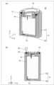
- FIG. 1(a) is a schematic perspective cross-sectional view showing a cross-sectional structure of a battery according to Embodiment 1 of the present disclosure
- FIG. 1(b) is a part of the cross-sectional structure of the sealing member in FIG. is a partial cross-sectional view showing (a) to (c) are schematic partial cross-sectional views showing each step in the method of manufacturing the sealing member.
- (a) is a schematic perspective cross-sectional view showing a cross-sectional structure of a battery according to Modification 1 of Embodiment 1 of the present disclosure, and (b) is a case where the cross-sectional view of (a) is the ZX plane; It is a schematic cross-sectional view showing the.
- (a) is a schematic perspective cross-sectional view showing a cross-sectional structure of a battery according to Modification 2 of Embodiment 1 of the present disclosure, and (b) is a case where the cross-sectional view of (a) is the ZX plane; It is a schematic cross-sectional view showing the.
- (a) is a schematic perspective cross-sectional view showing a cross-sectional structure of a battery according to Modification 3 of Embodiment 1 of the present disclosure, and (b) is a case where the cross-sectional view of (a) is the ZX plane; It is a schematic cross-sectional view showing the.
- the present inventors have investigated a sealed battery that can seal the battery can without forming a crimped portion by joining the battery can and the sealing member, for example, by welding. bottom.
- the sealing member of the battery is generally a gasket made of resin (such as polypropylene) crimped with a metal member having a thickness of several 100 ⁇ m.
- resin such as polypropylene
- the temperature rise of the gasket will be described in detail.
- the temperature of the welded portion where the end on the opening edge side and the end on the outer peripheral side of the sealing member are butt-welded is the melting point of the metal material used for the battery can and the sealing member (for example, the melting point of iron is about 1500° C.).
- the gasket is crimped with a metal member having a thickness of several hundred ⁇ m, and the distance to the welded portion is also several hundred ⁇ m.
- the gasket is made of polypropylene, the melting point is 140° C., which is about 1400° C. different from that of the welded portion, so the gasket may melt during welding.
- the sealing member is formed by caulking the gasket with a metal member having a thickness of several 100 ⁇ m.
- a metal member having a thickness of several 100 ⁇ m In the caulking process, two kinds of metal parts having different potentials in a battery are insulated and hermetically sealed. Therefore, resin is crushed by a metal member and hermetically sealed by the repulsive force of the resin. If the gasket melts due to welding, the gasket melts while being crushed by the metal member, so the melted resin may squirt out, preventing the resin from maintaining a sealed state and reducing the airtightness. There is If the airtightness of the sealing member deteriorates, the safety of the battery also deteriorates, so it is necessary to avoid melting of the gasket in sealing the battery.
- the present inventors examined the following battery according to the present disclosure as a battery capable of solving such problems.
- a battery in one aspect of the present disclosure includes a metal battery can, an electrode body, an electrolytic solution, and a sealing member.
- the battery can has a cylindrical portion with an opening edge at one end and a bottom closing the other end of the cylindrical portion.
- An electrode body is accommodated in the battery can.
- the battery can is filled with an electrolyte.
- the sealing member seals the opening edge of the cylindrical portion of the battery can.
- the sealing member is fixed such that the outer peripheral surface of the sealing member faces the inner peripheral surface of the opening edge. Specifically, a portion of the inner peripheral surface of the opening edge and a portion of the outer peripheral surface of the sealing member are fixed by being joined by the fusion zone. Further, an intermediate member made of a metal material having a melting point equal to or lower than the melting point of the metal material of the sealing member is provided on the upper surface of the sealing member.
- the intermediate member can suppress heat conduction to the gasket portion when the battery can and the sealing member are joined.
- the temperature rise of the gasket portion due to the heat transferred to the gasket portion side of the sealing member is suppressed.
- the temperature rise of the gasket portion due to the heat transferred to the gasket portion side of the sealing member is suppressed.
- the melting of the gasket portion can be suppressed. Therefore, it is possible to reduce airtightness failure of the sealing member due to heat during welding.
- the battery can can be sealed by welding, and the sealing member can be fixed to the battery can.
- annular protrusion also referred to as a diameter-reduced portion
- reduction can be achieved.
- the volume of the battery can can be reduced, and the energy density of the battery, which is the ratio of the battery energy to the volume of the battery can, is improved.
- a battery according to a first aspect includes a metal battery can having a cylindrical portion having an opening edge at one end and a bottom closing the other end of the cylindrical portion, and and a sealing member that is joined to the opening edge of the battery can and seals the opening of the opening edge.
- a ring portion and an intermediate member bonded to the top surface of the ring portion are included.
- the intermediate member may be made of a metal material having a melting point lower than that of the metal of the disc portion and the metal of the battery can.
- the sealing member may have the ring portion and the intermediate member joined by the first melting portion.
- a battery according to a fourth aspect is the battery according to the third aspect, wherein the first melted portion has a melted area on a surface where the ring portion and the gasket portion are in contact with each other at an interface between the ring portion and the intermediate member. It may be larger than the melting area.
- a battery according to a fifth aspect is the battery according to the third or fourth aspect, wherein the first fusion zone protrudes in the direction of the gasket part on the surface where the ring part and the gasket part are in contact. good.
- a battery according to a sixth aspect is the battery in any one of the first to fifth aspects, wherein the ring portion has a recess on an upper surface, and the intermediate member is joined to the ring portion so as to engage with the recess.
- the intermediate member may have an annular shape, and the diameter of the annular shape may be the same as the diameter of the battery can. .
- the thickness of the outer periphery of the intermediate member in the annular shape may be thinner than the thickness of the inner periphery.
- FIG. 1(a) is a schematic perspective cross-sectional view showing the cross-sectional structure of battery 10 according to Embodiment 1.
- FIG. FIG. 1(b) shows a cross-sectional view of the battery 10 according to Embodiment 1.
- the opening side of the battery can 11 is defined as the Z direction
- the direction perpendicular to the Z axis in the cross section including the Z axis is defined as the X direction
- the direction perpendicular to the Z and X axes is defined as the Y direction.
- the battery 10 includes a battery can 11 , a sealing member 12 , an electrolytic solution 14 and an electrode body 15 .
- the battery can 11 has a cylindrical portion 31 having an opening edge at one end and a bottom portion 32 closing the other end of the cylindrical portion 31 .
- the cylindrical portion 31 is, for example, a cylindrical portion
- the battery can 11 is a bottomed container having a cylindrical shape with an open upper end in the drawing.
- the battery can 11 is made of metal.
- the battery can 11 accommodates an electrode assembly 15 , and the battery can 11 is filled with an electrolytic solution 14 .
- the battery can 11 is sealed with a sealing member 12 .
- the space in which the electrode body 15 and the electrolytic solution 14 are housed inside the battery can 11 is a sealed space. Therefore, battery 10 according to Embodiment 1 is a sealed battery.
- the sealing member 12 forms a positive electrode portion by crimping a disc portion to the central portion through a gasket portion.
- the sealing member 12 has a disk shape, and has a shape in which the central portion is raised above the outer peripheral portion due to the presence of an intermediate member 20 to be described later.
- the sealing member 12 has an outer peripheral surface arranged to face the inner peripheral surface of the battery can 11 . The sealing member 12 is inserted into the battery can 11 so that the height of the upper end of the sealing member 12 in the drawing and the height of the upper end of the battery can 11 in the drawing are approximately the same.
- the electrode body 15 emits or absorbs electrons or ions into the battery can 11 depending on its material.
- the electrode body 15 has two types, a positive electrode and a negative electrode, and has a three-layer structure in which a separator is sandwiched between them to block the movement of electrons or ions.
- the electrode body 15 has positive and negative electrode tab portions through which electrons or ions flow respectively for the positive electrode and the negative electrode, but they are omitted in this drawing.
- the electrolytic solution 14 is a medium through which electrons or ions emitted from the electrode body 15 can move.
- the battery 10 of the present disclosure is manufactured through the following steps. (1) First, the electrode body 15 is inserted into the battery can 11, and the electrolytic solution 14 is injected. (2) Subsequently, as shown in FIG. 1(b), the battery is assembled so that the upper end of the inner peripheral surface of the battery can 11 and the upper end of the outer peripheral surface of the sealing member 12 are substantially aligned with each other. A sealing member 12 is inserted into the can 11 . (3) Subsequently, for example, the battery can 11 and part of the sealing member 12 are irradiated with a melting laser 16 . Also, the melting laser 16 is scanned along the circumferential direction of the outer periphery of the sealing member 12 .
- the battery 10 of the present disclosure is manufactured through the above steps.
- FIG. 2A is a schematic perspective view showing the appearance of the sealing member 12 in the battery 10 according to Embodiment 1
- FIG. 2B is a cross section of the sealing member 12 in FIG.
- FIG. 4 is a schematic partial cross-sectional view showing part of the structure
- the sealing member 12 includes an intermediate member 20, a ring portion 21, a gasket portion 22, and a disk portion 23.
- the ring portion 21 and the disk portion 23 are made of a metal material
- the gasket portion 22 is made of a resin material.
- the sealing member 12 is ring-shaped, for example.
- the disc portion 23 is crimped by the ring portion 21 through the gasket portion 22 . That is, as shown in FIG. 2B, the ring portion 21 has a disk portion 23 crimped to the central portion of the ring portion 21 via a gasket portion 22 .
- the sealing member 12 is electrically insulated from the disc portion 23 by the gasket portion 22 .
- An intermediate member 20 made of a metal material having a melting point lower than that of other metal materials of the sealing member is provided on the upper surface of the sealing member 12 .
- the metal material forming the ring portion 21 is the same as that of the battery can 11 .
- the metal material forming the intermediate member 20 is made of a metal material having a melting point lower than that of the metal material forming the ring portion 21 .
- the intermediate member 20 can suppress heat conduction to the gasket portion 22 when the battery can 11 and the sealing member 12 are joined.
- the intermediate member 20 and the ring portion 21 are superimposed and heated from the ring portion 21 side by, for example, a laser beam for bonding. Specifically, the intermediate member 20 is attached to the upper surface side of the ring portion 21 and welding is performed from the lower surface side with a welding laser 25 to form a dissimilar material fusion portion 26 .
- the melting point of the ring portion 21 is higher than the melting point of the intermediate member 20 as described above, the high melting point metal material side is heated. As a result, the amount of heat transmitted to the low melting point side can be suppressed, so the generation of intermetallic compounds due to mixing with the low melting point metal material can be suppressed, and the bonding strength can be maintained.
- the relationship between the surface fusion width 27 and the interface fusion width 28 at the interface between the sealing member 12 and the intermediate member 20 is surface fusion width 27 > interface fusion width 28 .
- the irradiation conditions are a wavelength of 1070 nm, an output of 250 W, a scanning speed of 500 mm/s, and a spot diameter of 20 ⁇ m. becomes.
- the dissimilar material melted portion 26 is in a state of protruding by several tens of ⁇ m in the melting direction compared to the surface before welding due to a change in crystal structure due to heat during welding.
- the sealing member 12 of the battery 10 is manufactured by crimping the disc portion 23 with the ring portion 21 via the gasket portion 22 .
- the sealing member 12 shown in FIG. 1 has a shape in which the central portion protrudes higher than the outer peripheral portion due to the presence of the intermediate member 20 . That is, battery 10 has a convex portion on the upper surface. However, it is desirable that the cell have flat surfaces.
- FIG. 4(a) is a schematic perspective cross-sectional view showing a cross-sectional structure of a battery 10a according to Modification 1 of Embodiment 1.
- FIG. 4(b) is a schematic cross-sectional view showing the case where the cross-sectional view of (a) is the ZX plane.
- the battery 10a includes a sealing member 12a.
- the sealing member 12a is manufactured so that the upper surface of the ring portion has unevenness, and the intermediate member 20 is fitted into the concave portion of the ring portion.
- the upper surface of the sealing member 12a can be flattened, so that the shape stability of the battery is high.
- the caulking structure of the sealing member 12a is complicated, and the cost is increased.
- FIG. 5(a) is a schematic perspective cross-sectional view showing a cross-sectional structure of a battery 10b according to Modification 2 of Embodiment 1
- FIG. 5(b) is a cross-sectional view of (a) taken along the ZX plane. It is a schematic sectional drawing which shows a certain case.
- the battery 10b includes a sealing member 12b.
- the sealing member 12b is manufactured so that the ring portion 21 has the same shape as in FIG.
- Modification 2 it is possible to achieve both simplification of the caulking structure and flattening of the upper surface of the sealing member 12b. Further, the intermediate member 20a stops at the edge of the battery can 11 when the sealing member 12b is inserted, thereby facilitating positioning. On the other hand, as a demerit, since the melted portion 18 of the same kind of material, which is the welded portion between the battery can 11 and the sealing member 12b in FIG. It is necessary.
- the intermediate member and the battery can do not necessarily need to be joined, and the sealing member 12b and the battery can only need to be joined.
- FIG. 6(a) is a schematic perspective cross-sectional view showing the cross-sectional structure of a battery 10c according to Modification 3 of Embodiment 1, and (b) shows the cross-sectional view of (a) taken along the ZX plane. It is a schematic cross-sectional view showing the.
- the battery 10c includes a sealing member 12c.
- the ring portion 21 of the sealing member 12c has the same shape as that of FIG. Manufactured in As a result, the same merits as those of the battery 10b can be obtained.
- the sealing member 12 is used to improve the melting efficiency because the laser-irradiated portion of the intermediate member 20b becomes thin when joining the ring portion 21, the intermediate member 20b, and the battery can 11 together. can be improved more.
- the intermediate member and the battery can are not necessarily joined, and the sealing member 12c and the battery can 11 only need to be joined.
- the shape of the battery can 11 is cylindrical in the present disclosure, the shape of the battery can 11 is not limited to this. For example, it may be an elliptical cylinder or a polygonal cylinder.
- the shape of the sealing member 12 is a disk shape in which the outer peripheral portion protrudes upward from the central portion, but the shape of the sealing member 12 is not limited to such a shape, and the outer peripheral surface of the sealing member 12 is a battery can. Any shape may be used as long as it can be inserted inside the opening edge so as to face the inner peripheral surface of the opening edge of 11 and can close the opening edge 17 .
- the configuration of the present disclosure may work effectively even when a battery module is manufactured by electrically connecting a plurality of batteries with current collector plates or the like.
- the battery module has a configuration in which the positive electrode of the battery is electrically connected to the sealing member and the negative electrode is electrically connected to the bottom of the can, so current collector plates are required above and below the battery.
- Japanese Patent Application Laid-Open No. 2021-93381 there are some efforts to reduce the required volume of the battery module and improve the volumetric energy density by collecting the current collectors on the upper side.
- An intermetallic compound layer is generally generated when metals with different melting points are mixed together.
- a metal material is joined to a sealing member, for example, when welding is performed, generally, the metal material and the sealing member are brought into close contact with each other, and heat is applied from the metal material side for welding.
- heat is applied from the low-melting-point metal side, most of the low-melting-point metal first melts during welding.
- the high-melting-point metal material melts with a time lag, it mixes with the metal on the low-melting-point side, so an intermetallic compound is generated and the joint strength of the weld is reduced.
- the present configuration proposes a construction method in which dissimilar materials are joined in the process of producing the sealing member.
- the battery according to the present disclosure can be used for various can-type batteries, and is useful for application as a power source for mobile devices, hybrid vehicles, electric vehicles, and the like.
Abstract
A battery according to the present invention is provided with: a battery can which is formed of a metal and comprises a cylindrical part having an open edge at one end, and a bottom part that closes the other end of the cylindrical part; an electrode body which is contained in the cylindrical part; and a sealing member which is joined to the open edge so as to seal the opening of the open edge. The sealing member comprises: a gasket part; a disk part that is formed of a metal; a ring part that swages the disk part to a center part by the intermediary of the gasket part; and an intermediate member that is joined to the upper surface of the ring part.
Description
本開示は、電池に関する。
This disclosure relates to batteries.
従来、封口された電池として様々な構成のものが知られている(例えば、特許文献1参照。)。このような従来の電池は、開口した端部を備えた電池缶を有し、電池缶の開口した端部を封口する。開口した端部を封口する方法として、次の方法が知られている。例えば、電極体を電池缶に収容後、電池缶の開口した端部の付近において、電池缶を内側に縮径する。この縮径によって、電池缶の内周面に環状の隆起が形成され、この隆起の上にガスケットおよび封口部材を載置する。その後、ガスケットを介して電池缶の開口した端部を封口部材にかしめて、封口部材の上にかしめ部を形成する。これによって、電池を封口し、密閉型電池を製造できる。
Conventionally, various configurations of sealed batteries are known (see Patent Document 1, for example). Such conventional batteries have a battery can with an open end, and the open end of the battery can is sealed. The following method is known as a method of sealing an open end. For example, after the electrode body is housed in the battery can, the diameter of the battery can is reduced inward near the open end of the battery can. This diameter reduction forms an annular ridge on the inner peripheral surface of the battery can, on which the gasket and sealing member are placed. Thereafter, the open end of the battery can is crimped to the sealing member through the gasket to form a crimped portion on the sealing member. Thereby, the battery can be sealed and a sealed battery can be manufactured.
しかし、溝部およびかしめ部を有する電池は、溝部の上に封口部材が載置され、封口部材の上にガスケットを介してかしめ部が形成されるため、封口板近傍の電池の高さ方向における寸法が大きくなり易い。これに伴い、特許文献1に記載の電池はエネルギー密度が低下し易いという課題があった。
However, in a battery having a groove and a crimped portion, the sealing member is placed on the groove and the crimped portion is formed on the sealing member via a gasket. tends to grow. As a result, the battery described in Patent Document 1 has a problem that the energy density tends to decrease.
したがって、本開示の目的は、上記従来の課題を解決することにあって、エネルギ密度の向上を実現できる電池を提供することにある。
Therefore, an object of the present disclosure is to solve the above-described conventional problems and to provide a battery capable of improving energy density.
本開示に係る電池は、一方の端部に開口縁部を有する筒部、および、筒部の他方の端部を閉じる底部を有する金属製の電池缶と、筒部の内部に収容された電極体と、電池缶の開孔縁部と接合され、開口縁部の開口を封口する封口部材と、を備える。封口部材は、ガスケット部と、金属製の円盤部と、ガスケット部を介して中心部に円盤部をかしめたリング部と、リング部の上面に接合された中間部材と、を含む。
A battery according to the present disclosure includes a metal battery can having a cylindrical portion having an opening edge at one end and a bottom closing the other end of the cylindrical portion, and an electrode housed inside the cylindrical portion. and a sealing member that is joined to the opening edge of the battery can and seals the opening of the opening edge. The sealing member includes a gasket portion, a metallic disk portion, a ring portion crimping the disk portion to the center through the gasket portion, and an intermediate member joined to the upper surface of the ring portion.
本開示に係る電池によれば、電池のエネルギ密度の向上を実現できる。
According to the battery according to the present disclosure, it is possible to improve the energy density of the battery.
(本開示に至った経緯)
従来における電池の封口方法では、かしめ部を形成した結果、封口部材近傍における電池の長手方向の寸法が増加し、電池のエネルギ密度は低下する。そこで、本発明者らは、従来の課題を解決するため、電池缶と封口部材とを、例えば、溶接により接合することで、かしめ部を形成せずに電池缶を封口できる密閉型電池を検討した。 (Circumstances leading to this disclosure)
In the conventional battery sealing method, as a result of forming the crimped portion, the longitudinal dimension of the battery increases in the vicinity of the sealing member, and the energy density of the battery decreases. Therefore, in order to solve the conventional problems, the present inventors have investigated a sealed battery that can seal the battery can without forming a crimped portion by joining the battery can and the sealing member, for example, by welding. bottom.
具体的には、電池缶の開口縁部に封口部材を挿入し、その突合せ面を溶接することで、電池缶を封口する手法を検討した。
Specifically, we investigated a method of sealing the battery can by inserting a sealing member into the edge of the opening of the battery can and welding the mating surfaces.
電池の封口部材は、一般的に、樹脂製(例えばポリプロピレンなど)のガスケットを厚み数100μmの金属部材でかしめられている。このような封口部材と電池缶とを溶接しようとすると、封口部材中でかしめられているガスケットに対し、溶接に伴う熱が加えられ、ガスケットが熱変形・溶融し気密不良が発生する原因となる。ここで、ガスケットの温度上昇について詳細に説明する。開口縁部側の端部と、封口部材の外周側の端部とを突合せ溶接した溶接部の温度は、電池缶および封口部材に用いられる金属材料の融点(例えば鉄の融点は約1500℃)まで上昇する。一方でガスケットは厚さ数百μmの金属部材でかしめられており、溶接部までの距離も同じく数100μmである。例えばガスケットがポリプロピレン製であるならば融点は140℃であり、溶接部と1400℃程度の差があるため、溶接中にガスケットが溶融する可能性がある。
The sealing member of the battery is generally a gasket made of resin (such as polypropylene) crimped with a metal member having a thickness of several 100 μm. When an attempt is made to weld such a sealing member and a battery can, the heat associated with welding is applied to the gasket crimped in the sealing member, causing thermal deformation and melting of the gasket, resulting in poor airtightness. . Here, the temperature rise of the gasket will be described in detail. The temperature of the welded portion where the end on the opening edge side and the end on the outer peripheral side of the sealing member are butt-welded is the melting point of the metal material used for the battery can and the sealing member (for example, the melting point of iron is about 1500° C.). rises to On the other hand, the gasket is crimped with a metal member having a thickness of several hundred μm, and the distance to the welded portion is also several hundred μm. For example, if the gasket is made of polypropylene, the melting point is 140° C., which is about 1400° C. different from that of the welded portion, so the gasket may melt during welding.
続いて、ガスケットの溶融による問題点について、詳細に説明する。前述の通り、封口部材はガスケットを厚み数100μmの金属部材でかしめられている。かしめ加工は、電池において電位の異なる2種の金属部を絶縁した状態で密閉するため、金属部材で樹脂を押しつぶし、樹脂の反発力によって密閉が行われている。ここで溶接によってガスケットが溶融すると、ガスケットが金属部材に押しつぶされた状態で溶融するため、溶けた樹脂材が外側に飛び出すなどして樹脂が密閉状態を維持できなくなり、気密性が低下する可能性がある。封口部材の気密性が低下すると、電池としての安全性も低下するため、電池の封口においてガスケットの溶融は避ける必要がある。
Next, we will explain in detail the problems caused by the melting of the gasket. As described above, the sealing member is formed by caulking the gasket with a metal member having a thickness of several 100 μm. In the caulking process, two kinds of metal parts having different potentials in a battery are insulated and hermetically sealed. Therefore, resin is crushed by a metal member and hermetically sealed by the repulsive force of the resin. If the gasket melts due to welding, the gasket melts while being crushed by the metal member, so the melted resin may squirt out, preventing the resin from maintaining a sealed state and reducing the airtightness. There is If the airtightness of the sealing member deteriorates, the safety of the battery also deteriorates, so it is necessary to avoid melting of the gasket in sealing the battery.
そこで、本発明者らは、このような課題を解決できる電池として、以下の本開示に係る電池を検討した。
Therefore, the present inventors examined the following battery according to the present disclosure as a battery capable of solving such problems.
本開示の一の態様における電池は、金属製の電池缶と、電極体と、電解液と、封口部材と、を備える。電池缶は、一方の端部に開口縁部を有する筒部、および、筒部の他方の端部を閉じる底部を有する。電池缶には電極体が収容される。電池缶は電解液で充填される。封口部材は、電池缶の筒部における開口縁部を封口する。封口部材の外周面が開口縁部の内周面と対向するように、封口部材は固定される。具体的には、開口縁部の内周面の一部と、封口部材の外周面の一部とが、溶融部により接合されることで固定されている。また、封口部材の上面に、封口部材の金属材料の融点以下となる融点を有する金属材料から成る中間部材が設けられている。
A battery in one aspect of the present disclosure includes a metal battery can, an electrode body, an electrolytic solution, and a sealing member. The battery can has a cylindrical portion with an opening edge at one end and a bottom closing the other end of the cylindrical portion. An electrode body is accommodated in the battery can. The battery can is filled with an electrolyte. The sealing member seals the opening edge of the cylindrical portion of the battery can. The sealing member is fixed such that the outer peripheral surface of the sealing member faces the inner peripheral surface of the opening edge. Specifically, a portion of the inner peripheral surface of the opening edge and a portion of the outer peripheral surface of the sealing member are fixed by being joined by the fusion zone. Further, an intermediate member made of a metal material having a melting point equal to or lower than the melting point of the metal material of the sealing member is provided on the upper surface of the sealing member.
このような構成によれば、中間部材は、電池缶と封口部材との接合時に、ガスケット部への熱伝導を抑制することができる。つまり、開口縁部の内周面の一部と、封口部材の外周面の一部とが、溶接される際、封口部材のガスケット部側へと伝熱する熱によるガスケット部の温度上昇を抑制できる。ガスケット部の温度上昇を抑制することで、ガスケット部の溶融を抑制できる。したがって、溶接時の熱における封口部材の気密不良の減少を実現できる。溶接によってガスケット部が溶融するとガスケット部が金属部材に押しつぶされた状態で溶融するため、溶けた樹脂材が外側に飛び出すなどして樹脂が密閉状態を維持できなくなることで気密性が低下する可能性がある。よって、溶接で電池缶を封口するとともに、封口部材を電池缶に固定することができる。従来の電池のように電池缶の内周面に環状の隆起(縮径部ともいう)および電池缶の開口した端部にかしめ部を設ける必要がないため、電極体と封口部材との距離の減少を実現できる。これによって、電池缶の体積を減少させることができ、電池エネルギと電池缶の体積との比である電池のエネルギ密度が向上する。
According to such a configuration, the intermediate member can suppress heat conduction to the gasket portion when the battery can and the sealing member are joined. In other words, when a portion of the inner peripheral surface of the opening edge and a portion of the outer peripheral surface of the sealing member are welded together, the temperature rise of the gasket portion due to the heat transferred to the gasket portion side of the sealing member is suppressed. can. By suppressing the temperature rise of the gasket portion, the melting of the gasket portion can be suppressed. Therefore, it is possible to reduce airtightness failure of the sealing member due to heat during welding. When the gasket melts due to welding, the gasket melts while being crushed by the metal member, so there is a possibility that the melted resin material will fly out and the resin will not be able to maintain a sealed state, resulting in a decrease in airtightness. There is Therefore, the battery can can be sealed by welding, and the sealing member can be fixed to the battery can. Unlike conventional batteries, it is not necessary to provide an annular protrusion (also referred to as a diameter-reduced portion) on the inner peripheral surface of the battery can and a crimped portion at the open end of the battery can. reduction can be achieved. As a result, the volume of the battery can can be reduced, and the energy density of the battery, which is the ratio of the battery energy to the volume of the battery can, is improved.
以下に、本開示の各態様について説明する。
Each aspect of the present disclosure will be described below.
第1の態様に係る電池は、一方の端部に開口縁部を有する筒部、および、筒部の他方の端部を閉じる底部を有する金属製の電池缶と、筒部の内部に収容された電極体と、電池缶の開口縁部と接合され、開口縁部の開口を封口する封口部材と、を備え、封口部材は、ガスケット部を介して中心部に金属製の円盤部をかしめたリング部と、リング部の上面に接合された中間部材と、を含む。
A battery according to a first aspect includes a metal battery can having a cylindrical portion having an opening edge at one end and a bottom closing the other end of the cylindrical portion, and and a sealing member that is joined to the opening edge of the battery can and seals the opening of the opening edge. A ring portion and an intermediate member bonded to the top surface of the ring portion are included.
第2の態様に係る電池は、上記第1の態様において、中間部材は、円盤部の金属および電池缶の金属の融点より低い融点を持つ金属材料で構成されていてもよい。
In the battery according to the second aspect, in the first aspect, the intermediate member may be made of a metal material having a melting point lower than that of the metal of the disc portion and the metal of the battery can.
第3の態様に係る電池は、上記第1又は第2の態様において、封口部材は、リング部と中間部材とを第一溶融部により接合されていてもよい。
In the battery according to the third aspect, in the first or second aspect, the sealing member may have the ring portion and the intermediate member joined by the first melting portion.
第4の態様に係る電池は、上記第3の態様において、前記第一溶融部は、前記リング部と前記ガスケット部との接する面における溶融面積が、前記リング部と前記中間部材との界面における溶融面積より大きくてもよい。
A battery according to a fourth aspect is the battery according to the third aspect, wherein the first melted portion has a melted area on a surface where the ring portion and the gasket portion are in contact with each other at an interface between the ring portion and the intermediate member. It may be larger than the melting area.
第5の態様に係る電池は、上記第3又は第4の態様において、前記第一溶融部は、前記リング部と前記ガスケット部との接する面において、前記ガスケット部の方向に隆起していてもよい。
A battery according to a fifth aspect is the battery according to the third or fourth aspect, wherein the first fusion zone protrudes in the direction of the gasket part on the surface where the ring part and the gasket part are in contact. good.
第6の態様に係る電池は、上記第1から5のいずれかの態様において、前記リング部は、上面に凹部を有し、前記中間部材は前記凹部に係合するよう前記リング部と接合されてもよい。
A battery according to a sixth aspect is the battery in any one of the first to fifth aspects, wherein the ring portion has a recess on an upper surface, and the intermediate member is joined to the ring portion so as to engage with the recess. may
第7の態様に係る電池は、上記第1から5のいずれかの態様において、前記中間部材は円環形状であり、前記円環形状の直径は前記電池缶の直径と同じであってもよい。
In a battery according to a seventh aspect, in any one of the first to fifth aspects, the intermediate member may have an annular shape, and the diameter of the annular shape may be the same as the diameter of the battery can. .
第8の態様に係る電池は、上記第7の態様において、前記中間部材は、前記円環形状における外周の厚さが内周の厚さより薄くてもよい。
In the battery according to the eighth aspect, in the seventh aspect, the thickness of the outer periphery of the intermediate member in the annular shape may be thinner than the thickness of the inner periphery.
以下、実施の形態に係る電池について、添付図面を参照しながら説明する。なお、図面において実質的に同一の部材については同一の符号を付している。
A battery according to an embodiment will be described below with reference to the accompanying drawings. In addition, the same code|symbol is attached|subjected about the substantially same member in drawing.
(実施の形態1)
以下、本開示の電池について、図面を参照しながら具体的に説明する。 (Embodiment 1)
Hereinafter, the battery of the present disclosure will be specifically described with reference to the drawings.
以下、本開示の電池について、図面を参照しながら具体的に説明する。 (Embodiment 1)
Hereinafter, the battery of the present disclosure will be specifically described with reference to the drawings.
まず、電池10の構成について図1を用いて説明する。図1(a)は、実施の形態1に係る電池10の断面構造を示す概略斜視断面図である。図1(b)は、実施の形態1に係る電池10の断面図を示す。なお、便宜上、電池缶11の開口の側をZ方向とし、Z軸を含む断面におけるZ軸と垂直な方向をX方向とし、Z軸及びX軸に垂直な方向をY方向としました。
First, the configuration of the battery 10 will be described using FIG. FIG. 1(a) is a schematic perspective cross-sectional view showing the cross-sectional structure of battery 10 according to Embodiment 1. FIG. FIG. 1(b) shows a cross-sectional view of the battery 10 according to Embodiment 1. FIG. For convenience, the opening side of the battery can 11 is defined as the Z direction, the direction perpendicular to the Z axis in the cross section including the Z axis is defined as the X direction, and the direction perpendicular to the Z and X axes is defined as the Y direction.
図1(a)に示すように、実施の形態に係る電池10は、電池缶11と、封口部材12と、電解液14と、電極体15と、を含む。
As shown in FIG. 1( a ), the battery 10 according to the embodiment includes a battery can 11 , a sealing member 12 , an electrolytic solution 14 and an electrode body 15 .
<電池缶>
電池缶11は、一方の端部に開口縁部を有する筒部31、および、筒部31の他方の端部を閉じる底部32を有する。実施の形態1において、筒部31は、例えば、円筒部であり、電池缶11は、図面上の上端が開口した円筒形状を有する有底容器である。電池缶11は金属製である。電池缶11には電極体15が収容され、電池缶11内に電解液14が充填されている。電池缶11は、封口部材12によって封口されている。電池缶11の内部における電極体15と電解液14とが収容された空間は、密閉された空間となっている。よって、実施の形態1に係る電池10は密閉型電池である。 <Battery can>
The battery can 11 has acylindrical portion 31 having an opening edge at one end and a bottom portion 32 closing the other end of the cylindrical portion 31 . In Embodiment 1, the cylindrical portion 31 is, for example, a cylindrical portion, and the battery can 11 is a bottomed container having a cylindrical shape with an open upper end in the drawing. The battery can 11 is made of metal. The battery can 11 accommodates an electrode assembly 15 , and the battery can 11 is filled with an electrolytic solution 14 . The battery can 11 is sealed with a sealing member 12 . The space in which the electrode body 15 and the electrolytic solution 14 are housed inside the battery can 11 is a sealed space. Therefore, battery 10 according to Embodiment 1 is a sealed battery.
電池缶11は、一方の端部に開口縁部を有する筒部31、および、筒部31の他方の端部を閉じる底部32を有する。実施の形態1において、筒部31は、例えば、円筒部であり、電池缶11は、図面上の上端が開口した円筒形状を有する有底容器である。電池缶11は金属製である。電池缶11には電極体15が収容され、電池缶11内に電解液14が充填されている。電池缶11は、封口部材12によって封口されている。電池缶11の内部における電極体15と電解液14とが収容された空間は、密閉された空間となっている。よって、実施の形態1に係る電池10は密閉型電池である。 <Battery can>
The battery can 11 has a
<封口部材>
封口部材12は、ガスケット部を介して中心部に円盤部をかしめることで、正極部を形成している。封口部材12は、円盤形状を有し、後述する中間部材20があることで、外周部分よりも中央部分が上方に隆起した形状を有する。封口部材12は、電池缶11の内周面と対向するように配置された外周面を有する。封口部材12の図面上の上端の高さと電池缶11の図面上の上端の高さとがおおむね一致するように、封口部材12は電池缶11内に挿入されている。 <Sealing material>
The sealingmember 12 forms a positive electrode portion by crimping a disc portion to the central portion through a gasket portion. The sealing member 12 has a disk shape, and has a shape in which the central portion is raised above the outer peripheral portion due to the presence of an intermediate member 20 to be described later. The sealing member 12 has an outer peripheral surface arranged to face the inner peripheral surface of the battery can 11 . The sealing member 12 is inserted into the battery can 11 so that the height of the upper end of the sealing member 12 in the drawing and the height of the upper end of the battery can 11 in the drawing are approximately the same.
封口部材12は、ガスケット部を介して中心部に円盤部をかしめることで、正極部を形成している。封口部材12は、円盤形状を有し、後述する中間部材20があることで、外周部分よりも中央部分が上方に隆起した形状を有する。封口部材12は、電池缶11の内周面と対向するように配置された外周面を有する。封口部材12の図面上の上端の高さと電池缶11の図面上の上端の高さとがおおむね一致するように、封口部材12は電池缶11内に挿入されている。 <Sealing material>
The sealing
<電極体>
電極体15は、その材質によって、電池缶11内に電子またはイオンを放出または吸収させる。電極体15は正極と負極との2種類を有し、その間に電子またはイオンの移動を遮るセパレータを挟んだ3層構造を有する。また、電極体15には正極、負極それぞれに対して電子、またはイオンの流れる正極・負極タブ部が存在しているが、本図面では割愛する。 <Electrode body>
Theelectrode body 15 emits or absorbs electrons or ions into the battery can 11 depending on its material. The electrode body 15 has two types, a positive electrode and a negative electrode, and has a three-layer structure in which a separator is sandwiched between them to block the movement of electrons or ions. The electrode body 15 has positive and negative electrode tab portions through which electrons or ions flow respectively for the positive electrode and the negative electrode, but they are omitted in this drawing.
電極体15は、その材質によって、電池缶11内に電子またはイオンを放出または吸収させる。電極体15は正極と負極との2種類を有し、その間に電子またはイオンの移動を遮るセパレータを挟んだ3層構造を有する。また、電極体15には正極、負極それぞれに対して電子、またはイオンの流れる正極・負極タブ部が存在しているが、本図面では割愛する。 <Electrode body>
The
<電極液>
電解液14は、電極体15より放出された電子またはイオンが移動できる媒体である。 <Electrode solution>
Theelectrolytic solution 14 is a medium through which electrons or ions emitted from the electrode body 15 can move.
電解液14は、電極体15より放出された電子またはイオンが移動できる媒体である。 <Electrode solution>
The
<電池の製造方法>
本開示の電池10は、次の工程を経て製造される。
(1)まず、電池缶11に電極体15を挿入し、電解液14が注入される。
(2)続いて、図1(b)に示すように、電池缶11の内周面の図面上の上端と、封口部材12の外周面の図面上の上端とがおおむね一致するように、電池缶11に封口部材12を挿入する。
(3)続いて、例えば、溶解用レーザ16を用いて、電池缶11と封口部材12の一部とに照射する。また、封口部材12の外周の周方向に沿って、溶解用レーザ16を走査させる。この照射によって、同種材溶融部18が形成され、封口部材12の外周は、筒部31の内周に接合される。その結果、電池缶11は封口され、封口部材12は電池缶11に固定される。 <Battery manufacturing method>
Thebattery 10 of the present disclosure is manufactured through the following steps.
(1) First, theelectrode body 15 is inserted into the battery can 11, and the electrolytic solution 14 is injected.
(2) Subsequently, as shown in FIG. 1(b), the battery is assembled so that the upper end of the inner peripheral surface of the battery can 11 and the upper end of the outer peripheral surface of the sealingmember 12 are substantially aligned with each other. A sealing member 12 is inserted into the can 11 .
(3) Subsequently, for example, the battery can 11 and part of the sealingmember 12 are irradiated with a melting laser 16 . Also, the melting laser 16 is scanned along the circumferential direction of the outer periphery of the sealing member 12 . By this irradiation, the same kind of material melted portion 18 is formed, and the outer periphery of the sealing member 12 is joined to the inner periphery of the tubular portion 31 . As a result, the battery can 11 is sealed and the sealing member 12 is fixed to the battery can 11 .
本開示の電池10は、次の工程を経て製造される。
(1)まず、電池缶11に電極体15を挿入し、電解液14が注入される。
(2)続いて、図1(b)に示すように、電池缶11の内周面の図面上の上端と、封口部材12の外周面の図面上の上端とがおおむね一致するように、電池缶11に封口部材12を挿入する。
(3)続いて、例えば、溶解用レーザ16を用いて、電池缶11と封口部材12の一部とに照射する。また、封口部材12の外周の周方向に沿って、溶解用レーザ16を走査させる。この照射によって、同種材溶融部18が形成され、封口部材12の外周は、筒部31の内周に接合される。その結果、電池缶11は封口され、封口部材12は電池缶11に固定される。 <Battery manufacturing method>
The
(1) First, the
(2) Subsequently, as shown in FIG. 1(b), the battery is assembled so that the upper end of the inner peripheral surface of the battery can 11 and the upper end of the outer peripheral surface of the sealing
(3) Subsequently, for example, the battery can 11 and part of the sealing
以上の工程によって、本開示の電池10が製造される。
The battery 10 of the present disclosure is manufactured through the above steps.
<封口部材の詳細>
次に、電池缶11の封口部材12の詳細について、図2を用いて説明する。図2(a)は、実施の形態1に係る電池10における封口部材12の外観を示す概略斜視図であり、(b)は、(a)の封口部材12のA-Aの方向からみた断面構造の一部を示す概略部分断面図である。 <Details of sealing material>
Next, details of the sealingmember 12 of the battery can 11 will be described with reference to FIG. 2A is a schematic perspective view showing the appearance of the sealing member 12 in the battery 10 according to Embodiment 1, and FIG. 2B is a cross section of the sealing member 12 in FIG. FIG. 4 is a schematic partial cross-sectional view showing part of the structure;
次に、電池缶11の封口部材12の詳細について、図2を用いて説明する。図2(a)は、実施の形態1に係る電池10における封口部材12の外観を示す概略斜視図であり、(b)は、(a)の封口部材12のA-Aの方向からみた断面構造の一部を示す概略部分断面図である。 <Details of sealing material>
Next, details of the sealing
図2(b)に示すように、封口部材12は、中間部材20、リング部21、ガスケット部22、円盤部23を含む。封口部材12において、リング部21および円盤部23は金属材料、ガスケット部22は樹脂材料によって形成される。
As shown in FIG. 2(b), the sealing member 12 includes an intermediate member 20, a ring portion 21, a gasket portion 22, and a disk portion 23. In the sealing member 12, the ring portion 21 and the disk portion 23 are made of a metal material, and the gasket portion 22 is made of a resin material.
封口部材12は、例えばリング状である。円盤部23はリング部21によってガスケット部22を介してかしめられている。すなわち、図2(b)に示すように、リング部21は、ガスケット部22を介して、リング部21の中心部に円盤部23をかしめている。封口部材12は、ガスケット部22によって円盤部23と電気的に絶縁されている。
The sealing member 12 is ring-shaped, for example. The disc portion 23 is crimped by the ring portion 21 through the gasket portion 22 . That is, as shown in FIG. 2B, the ring portion 21 has a disk portion 23 crimped to the central portion of the ring portion 21 via a gasket portion 22 . The sealing member 12 is electrically insulated from the disc portion 23 by the gasket portion 22 .
封口部材12の上面には、封口部材の他の金属材料の融点よりも低い融点を有する金属材料から成る中間部材20が設けられている。
An intermediate member 20 made of a metal material having a melting point lower than that of other metal materials of the sealing member is provided on the upper surface of the sealing member 12 .
リング部21を構成する金属材料は、電池缶11と同様である。中間部材20を構成する金属材料は、リング部21を構成する金属材料の融点よりも低い融点を持つ金属材料で構成される。
The metal material forming the ring portion 21 is the same as that of the battery can 11 . The metal material forming the intermediate member 20 is made of a metal material having a melting point lower than that of the metal material forming the ring portion 21 .
この電池10によれば、中間部材20は、電池缶11と封口部材12との接合時に、ガスケット部22への熱伝導を抑制することができる。
According to this battery 10, the intermediate member 20 can suppress heat conduction to the gasket portion 22 when the battery can 11 and the sealing member 12 are joined.
<封口部材の製造方法>
次に、封口部材12の製造方法について、図3を用いて説明する。 <Manufacturing method of sealing member>
Next, a method for manufacturing the sealingmember 12 will be described with reference to FIG.
次に、封口部材12の製造方法について、図3を用いて説明する。 <Manufacturing method of sealing member>
Next, a method for manufacturing the sealing
(a)まずはじめに、図3(a)に示すように、中間部材20とリング部21とを重ね合わせ、リング部21側から、例えばレーザ光によって加熱し、接合を行う。具体的には、リング部21の上面側に中間部材20を取り付け、下面側から溶接用レーザ25で溶接を行い、異種材溶融部26を形成する。
(a) First, as shown in FIG. 3(a), the intermediate member 20 and the ring portion 21 are superimposed and heated from the ring portion 21 side by, for example, a laser beam for bonding. Specifically, the intermediate member 20 is attached to the upper surface side of the ring portion 21 and welding is performed from the lower surface side with a welding laser 25 to form a dissimilar material fusion portion 26 .
ここで、前述のようにリング部21の融点は、中間部材20の融点よりも高いため、高融点金属材料側から加熱することになる。これにより、低融点側へ伝わる熱量を抑制することができるため、低融点側の金属材料との混合による金属間化合物の発生を抑制でき、接合強度を保つことができる。
Here, since the melting point of the ring portion 21 is higher than the melting point of the intermediate member 20 as described above, the high melting point metal material side is heated. As a result, the amount of heat transmitted to the low melting point side can be suppressed, so the generation of intermetallic compounds due to mixing with the low melting point metal material can be suppressed, and the bonding strength can be maintained.
異種材溶融部26において、表面溶融幅27と、封口部材12と中間部材20との界面における界面溶融幅28の大きさの関係は、表面溶融幅27>界面溶融幅28となる。例えばレーザにて接合を行うのであれば、照射条件を波長1070nm、出力250W、走査速度500mm/s、スポット径20μmにて接合を行うと、表面溶融幅は約200μm、界面溶融幅は約150μm程度となる。
In the dissimilar material fusion zone 26 , the relationship between the surface fusion width 27 and the interface fusion width 28 at the interface between the sealing member 12 and the intermediate member 20 is surface fusion width 27 > interface fusion width 28 . For example, if a laser is used for bonding, the irradiation conditions are a wavelength of 1070 nm, an output of 250 W, a scanning speed of 500 mm/s, and a spot diameter of 20 μm. becomes.
またここで、異種材溶融部26は溶接時の熱による結晶構造の変化により、溶接前の表面と比較すると、溶融方向に対して数10μm程隆起した状態となる。
Also, here, the dissimilar material melted portion 26 is in a state of protruding by several tens of μm in the melting direction compared to the surface before welding due to a change in crystal structure due to heat during welding.
(b)次に、図3(b)に示すように、リング部21にガスケット部22、円盤部23を挿入する。
(b) Next, the gasket portion 22 and the disk portion 23 are inserted into the ring portion 21 as shown in FIG. 3(b).
(c)最後に、図3(c)に示すように、円盤部23をリング部21によってガスケット部22を介してかしめることで、電池10の封口部材12が製造される。
(c) Finally, as shown in FIG. 3(c), the sealing member 12 of the battery 10 is manufactured by crimping the disc portion 23 with the ring portion 21 via the gasket portion 22 .
ここで、図3(c)に示す、ガスケット部22がかしめられたリング部21においては、ガスケットの気密は、それぞれリング部21とガスケット部22との密着、及び、ガスケット部22と円盤部23との密着によって確保されている。この密着度は、ガスケット部22が圧縮され、封口部材12の断面におけるリング部21と円盤部23とに挟まれたガスケット部22の厚さである、ガスケット圧縮長さ29が、元のガスケット部22の厚さから小さくなるほど向上する。前述したように異種材溶融部26は、ガスケット部22の方向に隆起しているため、異種材溶融部26におけるガスケット圧縮長さ29は、異種材溶融部26の隆起により未溶接位置と比較して短くなる。したがってガスケットの密着度は向上するため、異種材溶融部26を有する封口部材12は、より高い気密状態の確保が可能である。
Here, in the ring portion 21 to which the gasket portion 22 is crimped as shown in FIG. ensured by close contact with This degree of adhesion is the thickness of the gasket portion 22 sandwiched between the ring portion 21 and the disk portion 23 in the cross section of the sealing member 12 when the gasket portion 22 is compressed. 22, the smaller the thickness, the better. As described above, since the dissimilar material melted portion 26 protrudes toward the gasket portion 22, the gasket compression length 29 at the dissimilar material melted portion 26 is larger than the unwelded position due to the protrusion of the dissimilar material melted portion 26. shorter. Therefore, since the degree of adhesion of the gasket is improved, the sealing member 12 having the dissimilar material melted portion 26 can ensure a higher airtight state.
ここで、前述したように、図1に示す封口部材12は、中間部材20があることで、外周部分よりも中央部分が上方に隆起した形状を有する。すなわち、電池10は、上面に凸部を有する。しかし、電池は平坦な面を有することが望ましい。
Here, as described above, the sealing member 12 shown in FIG. 1 has a shape in which the central portion protrudes higher than the outer peripheral portion due to the presence of the intermediate member 20 . That is, battery 10 has a convex portion on the upper surface. However, it is desirable that the cell have flat surfaces.
(変形例1)
また、本実施の形態1の変形例1に係る封口部材を以下のように製造することができる。図4(a)は、実施の形態1の変形例1に係る電池10aの断面構造を示す概略斜視断面図である。図4(b)は、(a)の断面図がZ-X面である場合を示す概略断面図である。 (Modification 1)
Moreover, the sealing member according toModification 1 of Embodiment 1 can be manufactured as follows. FIG. 4(a) is a schematic perspective cross-sectional view showing a cross-sectional structure of a battery 10a according to Modification 1 of Embodiment 1. FIG. FIG. 4(b) is a schematic cross-sectional view showing the case where the cross-sectional view of (a) is the ZX plane.
また、本実施の形態1の変形例1に係る封口部材を以下のように製造することができる。図4(a)は、実施の形態1の変形例1に係る電池10aの断面構造を示す概略斜視断面図である。図4(b)は、(a)の断面図がZ-X面である場合を示す概略断面図である。 (Modification 1)
Moreover, the sealing member according to
電池10aは、封口部材12aを含む。封口部材12aは、リング部の上面に凹凸があり、中間部材20がリング部の凹部に嵌め合うよう製造されている。
The battery 10a includes a sealing member 12a. The sealing member 12a is manufactured so that the upper surface of the ring portion has unevenness, and the intermediate member 20 is fitted into the concave portion of the ring portion.
本変形例1のメリットとして、封口部材12aの上面を平坦化することが可能なため、電池としての形状安定性が高いことが挙げられる。一方でデメリットとして、図1の封口部材12に対して封口部材12aのかしめ構造が複雑化し、高コスト化することが挙げられる。
As an advantage of Modification 1, the upper surface of the sealing member 12a can be flattened, so that the shape stability of the battery is high. On the other hand, as a demerit, compared to the sealing member 12 of FIG. 1, the caulking structure of the sealing member 12a is complicated, and the cost is increased.
(変形例2)
また、本実施の形態1の変形例2に係る封口部材12bをさらに以下のように製造してもよい。図5(a)は、実施の形態1の変形例2に係る電池10bの断面構造を示す概略斜視断面図であり、図5(b)は、(a)の断面図がZ-X面である場合を示す概略断面図である。 (Modification 2)
Further, the sealingmember 12b according to Modification 2 of Embodiment 1 may be further manufactured as follows. FIG. 5(a) is a schematic perspective cross-sectional view showing a cross-sectional structure of a battery 10b according to Modification 2 of Embodiment 1, and FIG. 5(b) is a cross-sectional view of (a) taken along the ZX plane. It is a schematic sectional drawing which shows a certain case.
また、本実施の形態1の変形例2に係る封口部材12bをさらに以下のように製造してもよい。図5(a)は、実施の形態1の変形例2に係る電池10bの断面構造を示す概略斜視断面図であり、図5(b)は、(a)の断面図がZ-X面である場合を示す概略断面図である。 (Modification 2)
Further, the sealing
電池10bは、封口部材12bを含む。封口部材12bは、リング部21は図1と同じ形状で、中間部材20aの直径が筒部31の直径と一致するよう製造されている。
The battery 10b includes a sealing member 12b. The sealing member 12b is manufactured so that the ring portion 21 has the same shape as in FIG.
本変形例2のメリットとして、かしめ構造の簡易化と封口部材12bの上面の平坦化の両立が可能であることが挙げられる。また、封口部材12bの挿入時に中間部材20aが電池缶11の縁部で止まることで位置決めの容易化が可能である。一方でデメリットとして、図5(b)の電池缶11と封口部材12bとの溶接個所である同種材溶融部18の溶け込みが甘くなるため、溶解用レーザ16をより強い出力であてるなどの工夫が必要になることである。
As an advantage of Modification 2, it is possible to achieve both simplification of the caulking structure and flattening of the upper surface of the sealing member 12b. Further, the intermediate member 20a stops at the edge of the battery can 11 when the sealing member 12b is inserted, thereby facilitating positioning. On the other hand, as a demerit, since the melted portion 18 of the same kind of material, which is the welded portion between the battery can 11 and the sealing member 12b in FIG. It is necessary.
なお、この構造においては中間部材と電池缶は必ずしも接合される必要はなく、封口部材12bと電池缶が接合されればよい。
It should be noted that in this structure, the intermediate member and the battery can do not necessarily need to be joined, and the sealing member 12b and the battery can only need to be joined.
(変形例3)
さらに、本実施の形態1の変形例3に係る封口部材を以下のように製造してもよい。図6(a)は、実施の形態1の変形例3に係る電池10cの断面構造を示す概略斜視断面図であり、(b)は、(a)の断面図がZ-X面である場合を示す概略断面図である。 (Modification 3)
Further, the sealing member according to Modification 3 ofEmbodiment 1 may be manufactured as follows. FIG. 6(a) is a schematic perspective cross-sectional view showing the cross-sectional structure of a battery 10c according to Modification 3 of Embodiment 1, and (b) shows the cross-sectional view of (a) taken along the ZX plane. It is a schematic cross-sectional view showing the.
さらに、本実施の形態1の変形例3に係る封口部材を以下のように製造してもよい。図6(a)は、実施の形態1の変形例3に係る電池10cの断面構造を示す概略斜視断面図であり、(b)は、(a)の断面図がZ-X面である場合を示す概略断面図である。 (Modification 3)
Further, the sealing member according to Modification 3 of
電池10cは、封口部材12cを含む。封口部材12cは、リング部21は図1と同じ形状で、中間部材20bの直径が筒部31の直径と一致し、かつ中間部材20bの厚さが内周側より外周側のほうが薄くなるように製造されている。このことにより、電池10bと同様のメリットが得られる、また、リング部21と中間部材20bと電池缶11との接合において中間部材20bのレーザ照射部が薄くなるため溶融効率を封口部材12を用いるよりも向上させることが可能である。一方でデメリットとして図1の中間部材20や図5の中間部材20aに対して図6の中間部材20bは形状が複雑化するため高コスト化することが挙げられる。
The battery 10c includes a sealing member 12c. The ring portion 21 of the sealing member 12c has the same shape as that of FIG. Manufactured in As a result, the same merits as those of the battery 10b can be obtained. In addition, the sealing member 12 is used to improve the melting efficiency because the laser-irradiated portion of the intermediate member 20b becomes thin when joining the ring portion 21, the intermediate member 20b, and the battery can 11 together. can be improved more. On the other hand, as a demerit, compared with the intermediate member 20 of FIG. 1 and the intermediate member 20a of FIG. 5, the shape of the intermediate member 20b of FIG.
なお、この構造においては中間部材と電池缶は必ずしも接合される必要はなく、封口部材12cと電池缶11とが接合されればよい。
It should be noted that in this structure, the intermediate member and the battery can are not necessarily joined, and the sealing member 12c and the battery can 11 only need to be joined.
なお、本開示においては、電池缶11の形状を円筒としているが、電池缶11の形状はこのようなものに限られない。例えば、楕円筒または多角筒であってもよい。
Although the shape of the battery can 11 is cylindrical in the present disclosure, the shape of the battery can 11 is not limited to this. For example, it may be an elliptical cylinder or a polygonal cylinder.
なお、本開示においては、封口部材12の形状を中央部分よりも外周部分が上方に隆起した円盤形状としているが、封口部材12の形状はこのようなものに限られず、その外周面が電池缶11の開口縁部の内周面と対向するように開口縁部の内側に挿入され、開口縁部17を封口できる形状であればよい。
In the present disclosure, the shape of the sealing member 12 is a disk shape in which the outer peripheral portion protrudes upward from the central portion, but the shape of the sealing member 12 is not limited to such a shape, and the outer peripheral surface of the sealing member 12 is a battery can. Any shape may be used as long as it can be inserted inside the opening edge so as to face the inner peripheral surface of the opening edge of 11 and can close the opening edge 17 .
また、本開示の構成は、複数の電池を集電板などで電位的に接続し電池モジュールを作製する場合にも有効に働く場合がある。現状、電池モジュールは、電池の正極を封口部材、負極を缶底で電気的に接続しているため電池の上下に集電板が必要な構成となっている。特開2021-93381号公報のように一部では集電部を上側に集めることで、電池モジュールの必要体積を減らし、体積エネルギー密度を向上させる取り組みがある。
In addition, the configuration of the present disclosure may work effectively even when a battery module is manufactured by electrically connecting a plurality of batteries with current collector plates or the like. At present, the battery module has a configuration in which the positive electrode of the battery is electrically connected to the sealing member and the negative electrode is electrically connected to the bottom of the can, so current collector plates are required above and below the battery. As in Japanese Patent Application Laid-Open No. 2021-93381, there are some efforts to reduce the required volume of the battery module and improve the volumetric energy density by collecting the current collectors on the upper side.
集電板の接続を溶接にて行う場合を考える。集電板の材質は多くの場合、銅、アルミなどの抵抗の低い金属が用いられる。円筒二次電池は正極である封口部材はアルミ、缶は鉄で構成されている場合が多い。この場合、アルミもしくは銅と鉄の異種材溶接となるため溶接の難易度が高くなる。一方、今回の構成では封口部材上に熱伝導率の高い金属、アルミまたは銅等を接合する。封口部材上に接合する金属と電池を電気的に接続するバスバー部材を同種材になるよう選択すれば、電池モジュールを作製する際、同種材溶接を行うことができる。これは、電池を購入し、電池モジュールを組み立てるEVメーカー等に対しては溶接を平易にすることに繋がる。
Consider the case where the current collector plate is connected by welding. Current collectors are often made of low-resistance metals such as copper and aluminum. Cylindrical secondary batteries often have a sealing member, which is a positive electrode, made of aluminum, and a can made of iron. In this case, welding becomes more difficult because dissimilar materials such as aluminum or copper and iron are welded. On the other hand, in the present configuration, a metal having a high thermal conductivity, such as aluminum or copper, is bonded onto the sealing member. If the busbar member for electrically connecting the metal to be joined on the sealing member and the battery is selected to be of the same material, it is possible to weld the same material when fabricating the battery module. This leads to easier welding for EV manufacturers who purchase batteries and assemble battery modules.
しかし、封口部材の上面に封口部材の金属材料の融点以下となる融点を有する金属材料を接合する場合にも、前記の通り異種材溶接となるため溶接の難易度が高くなる問題が発生する。特に充分な熱引き効果を得ようとする場合、融点が大きく離れた金属材料、主に封口部材の材料である鉄に対して、アルミや銅を用いる必要がある。この異種材接合は金属材料の組み合わせによっては接合部中に金属間化合物層という脆弱な層が発生する。金属間化合物層の影響で封口部材の上面への金属材料の接合は充分な接合強度を得ることは難しい。
However, even when a metal material having a melting point equal to or lower than the melting point of the metal material of the sealing member is joined to the upper surface of the sealing member, the welding becomes more difficult as described above due to the welding of dissimilar materials. In particular, when attempting to obtain a sufficient heat transfer effect, it is necessary to use aluminum or copper as opposed to metal materials whose melting points are far apart, such as iron, which is mainly the material of the sealing member. In this dissimilar material joining, a fragile layer called an intermetallic compound layer is generated in the joining part depending on the combination of metal materials. Due to the influence of the intermetallic compound layer, it is difficult to obtain sufficient bonding strength when bonding the metal material to the upper surface of the sealing member.
金属間化合物層は、一般的に融点の異なる金属同士が混ざり合った際に発生する。封口部材に対して金属材料を接合する場合、例えば溶接を行う場合では一般的に金属材料と封口部材とを密着させ、金属材料側から熱を加え溶接する手段をとる。この場合、低融点の金属側から熱を加えるため、溶接時は低融点側の金属の大部分が先に溶融状態となる。その場合、高融点金属材料が遅れて時間差で溶融する際、低融点側の金属と混ざるため、金属間化合物が発生し、溶接部の接合強度が低下する。
An intermetallic compound layer is generally generated when metals with different melting points are mixed together. When a metal material is joined to a sealing member, for example, when welding is performed, generally, the metal material and the sealing member are brought into close contact with each other, and heat is applied from the metal material side for welding. In this case, since heat is applied from the low-melting-point metal side, most of the low-melting-point metal first melts during welding. In this case, when the high-melting-point metal material melts with a time lag, it mixes with the metal on the low-melting-point side, so an intermetallic compound is generated and the joint strength of the weld is reduced.
融点の大きく異なる異種材接合で十分な接合強度を得るため、高融点金属材料側からの加工が重要である。これを達成するため、本構成では封口部材を作製する工程において異種材接合を行う工法を提案する。
In order to obtain sufficient bonding strength by joining dissimilar materials with greatly different melting points, it is important to process from the high-melting-point metal material side. In order to achieve this, the present configuration proposes a construction method in which dissimilar materials are joined in the process of producing the sealing member.
なお、本開示においては、前述した様々な実施の形態及び/又は実施例のうちの任意の実施の形態及び/又は実施例を適宜組み合わせることを含むものであり、それぞれの実施の形態及び/又は実施例が有する効果を奏することができる。
It should be noted that the present disclosure includes appropriate combinations of any of the various embodiments and / or examples described above, and each embodiment and / or The effects of the embodiment can be obtained.
本開示に係る電池は、種々の缶型の電池に利用可能であり、例えば携帯機器、ハイブリッド自動車、電気自動車等の電源としての適用が有用である。
The battery according to the present disclosure can be used for various can-type batteries, and is useful for application as a power source for mobile devices, hybrid vehicles, electric vehicles, and the like.
10、10a、10b、10c 電池
11 電池缶
12、12a、12b、12c 封口部材
14 電解液
15 電極体
16 溶解用レーザ
17 開口縁部
18 同種材溶融部
20、20a、20b 中間部材
21 リング部
22 ガスケット部
23 円盤部
25 溶接用レーザ
26 異種材溶融部
27 表面溶融幅
28 界面溶融幅
29 ガスケット圧縮長さ
31 筒部
32 底部 REFERENCE SIGNS LIST 10, 10a, 10b, 10c battery 11 battery can 12, 12a, 12b, 12c sealing member 14 electrolytic solution 15 electrode body 16 melting laser 17 opening edge 18 similar material melting portion 20, 20a, 20b intermediate member 21 ring portion 22 Gasket part 23 Disk part 25 Welding laser 26 Dissimilar material fusion zone 27 Surface fusion width 28 Interfacial fusion width 29 Gasket compression length 31 Cylindrical part 32 Bottom part
11 電池缶
12、12a、12b、12c 封口部材
14 電解液
15 電極体
16 溶解用レーザ
17 開口縁部
18 同種材溶融部
20、20a、20b 中間部材
21 リング部
22 ガスケット部
23 円盤部
25 溶接用レーザ
26 異種材溶融部
27 表面溶融幅
28 界面溶融幅
29 ガスケット圧縮長さ
31 筒部
32 底部 REFERENCE SIGNS
Claims (8)
- 一方の端部に開口縁部を有する筒部、および、前記筒部の他方の端部を閉じる底部を有する金属製の電池缶と、
前記筒部の内部に収容された電極体と、
前記電池缶の前記開口縁部と接合され、前記開口縁部の開口を封口する封口部材と、を備え、
前記封口部材は、
ガスケット部と、
金属製の円盤部と、
前記ガスケット部を介して中心部に前記円盤部をかしめたリング部と、
前記リング部の上面に接合された中間部材と、を含む、
電池。 A metal battery can having a cylindrical portion with an opening edge at one end and a bottom closing the other end of the cylindrical portion;
an electrode body housed inside the tubular portion;
a sealing member that is joined to the opening edge of the battery can and seals the opening of the opening edge,
The sealing member is
a gasket part;
a metallic disk;
a ring portion in which the disk portion is crimped to the center through the gasket portion;
an intermediate member bonded to the top surface of the ring portion;
battery. - 前記中間部材は、前記円盤部の金属および前記電池缶の金属の融点より低い融点を持つ金属材料で構成されている、
請求項1に記載の電池。 The intermediate member is made of a metal material having a melting point lower than that of the metal of the disk portion and the metal of the battery can,
A battery according to claim 1 . - 前記封口部材は、前記リング部と前記中間部材とを第一溶融部により接合されている、
請求項1または2に記載の電池。 In the sealing member, the ring portion and the intermediate member are joined by a first melting portion,
The battery according to claim 1 or 2. - 前記第一溶融部は、前記リング部と前記ガスケット部との接する面における溶融面積が、前記リング部と前記中間部材との界面における溶融面積より大きい、
請求項3に記載の電池。 In the first melted portion, the melted area on the contact surface between the ring portion and the gasket portion is larger than the melted area on the interface between the ring portion and the intermediate member.
The battery according to claim 3. - 前記第一溶融部は、前記リング部と前記ガスケット部との接する面において、前記ガスケット部の方向に隆起している、
請求項3または4に記載の電池。 The first fusion zone protrudes in the direction of the gasket part on the contact surface between the ring part and the gasket part,
The battery according to claim 3 or 4. - 前記リング部は、上面に凹部を有し、前記中間部材は前記凹部に係合するよう前記リング部と接合される、
請求項1から5のいずれか1項に記載の電池。 The ring portion has a recess in its upper surface, and the intermediate member is joined to the ring portion so as to engage with the recess.
The battery according to any one of claims 1 to 5. - 前記中間部材は円環形状であり、前記円環形状の直径は前記電池缶の直径と同じである、
請求項1から5のいずれか1項に記載の電池。 The intermediate member has an annular shape, and the diameter of the annular shape is the same as the diameter of the battery can.
The battery according to any one of claims 1 to 5. - 前記中間部材は、前記円環形状における外周の厚さが内周の厚さより薄い、
請求項7に記載の電池。 In the intermediate member, the thickness of the outer periphery of the annular shape is thinner than the thickness of the inner periphery,
A battery according to claim 7 .
Applications Claiming Priority (2)
| Application Number | Priority Date | Filing Date | Title |
|---|---|---|---|
| JP2021-186345 | 2021-11-16 | ||
| JP2021186345 | 2021-11-16 |
Publications (1)
| Publication Number | Publication Date |
|---|---|
| WO2023089869A1 true WO2023089869A1 (en) | 2023-05-25 |
Family
ID=86396585
Family Applications (1)
| Application Number | Title | Priority Date | Filing Date |
|---|---|---|---|
| PCT/JP2022/028253 WO2023089869A1 (en) | 2021-11-16 | 2022-07-20 | Battery |
Country Status (1)
| Country | Link |
|---|---|
| WO (1) | WO2023089869A1 (en) |
Citations (4)
| Publication number | Priority date | Publication date | Assignee | Title |
|---|---|---|---|---|
| JPH07183011A (en) * | 1993-12-22 | 1995-07-21 | Furukawa Battery Co Ltd:The | Manufacture of square sealed battery |
| JPH117922A (en) * | 1997-06-18 | 1999-01-12 | Mitsubishi Cable Ind Ltd | Sealing structure for sealed battery |
| JP2013542567A (en) * | 2010-12-07 | 2013-11-21 | エルジー・ケム・リミテッド | Cap assembly and secondary battery using the same |
| JP2015099681A (en) * | 2013-11-19 | 2015-05-28 | 日立マクセル株式会社 | Sealed battery |
-
2022
- 2022-07-20 WO PCT/JP2022/028253 patent/WO2023089869A1/en unknown
Patent Citations (4)
| Publication number | Priority date | Publication date | Assignee | Title |
|---|---|---|---|---|
| JPH07183011A (en) * | 1993-12-22 | 1995-07-21 | Furukawa Battery Co Ltd:The | Manufacture of square sealed battery |
| JPH117922A (en) * | 1997-06-18 | 1999-01-12 | Mitsubishi Cable Ind Ltd | Sealing structure for sealed battery |
| JP2013542567A (en) * | 2010-12-07 | 2013-11-21 | エルジー・ケム・リミテッド | Cap assembly and secondary battery using the same |
| JP2015099681A (en) * | 2013-11-19 | 2015-05-28 | 日立マクセル株式会社 | Sealed battery |
Similar Documents
| Publication | Publication Date | Title |
|---|---|---|
| JP6093874B2 (en) | Prismatic secondary battery | |
| JP5213404B2 (en) | Sealed battery and manufacturing method thereof | |
| JP5449961B2 (en) | Secondary battery | |
| JP5862682B2 (en) | Battery container and manufacturing method thereof | |
| KR20100087374A (en) | Method of producing welded structure and method of producing battery | |
| JPWO2006016441A1 (en) | Dissimilar metal sheet welding method, dissimilar metal sheet assembly, electric device and electric device assembly | |
| WO2015072010A1 (en) | Prismatic battery | |
| US20160254565A1 (en) | Second battery and method of producing the same | |
| JP2010093178A (en) | Electrochemical capacitance and method of manufacturing the same | |
| US20120248076A1 (en) | Laser welding method and battery made by the same | |
| JP2011204396A (en) | Sealed battery and method for manufacturing the same | |
| US20210167455A1 (en) | Battery module and method for manufacturing same | |
| WO2015025388A1 (en) | Secondary cell | |
| US20090029244A1 (en) | Battery, and battery manufacturing method | |
| US20060127759A1 (en) | Lactobacillus casei bd-II strain and used to reduce blood | |
| JP2005183360A (en) | Square battery and its manufacturing method | |
| KR102467767B1 (en) | A secondary battery | |
| WO2023089869A1 (en) | Battery | |
| JP5051986B2 (en) | Battery pack and manufacturing method thereof | |
| JP2010118374A (en) | Capacitor | |
| WO2020066241A1 (en) | Secondary battery | |
| JP2010010166A (en) | Method of manufacturing capacitor | |
| US20220085464A1 (en) | Terminal, secondary battery provided with same, and methods for producing same | |
| US20220085462A1 (en) | Terminal, secondary battery including same, and manufacturing method thereof | |
| JP2023015619A (en) | Secondary battery, electrode component thereof, and assembled battery |
Legal Events
| Date | Code | Title | Description |
|---|---|---|---|
| 121 | Ep: the epo has been informed by wipo that ep was designated in this application |
Ref document number: 22895158 Country of ref document: EP Kind code of ref document: A1 |