WO2023085267A1 - データ転送装置およびデータ転送方法 - Google Patents
データ転送装置およびデータ転送方法 Download PDFInfo
- Publication number
- WO2023085267A1 WO2023085267A1 PCT/JP2022/041555 JP2022041555W WO2023085267A1 WO 2023085267 A1 WO2023085267 A1 WO 2023085267A1 JP 2022041555 W JP2022041555 W JP 2022041555W WO 2023085267 A1 WO2023085267 A1 WO 2023085267A1
- Authority
- WO
- WIPO (PCT)
- Prior art keywords
- data
- packet
- service
- data processing
- service function
- Prior art date
- Legal status (The legal status is an assumption and is not a legal conclusion. Google has not performed a legal analysis and makes no representation as to the accuracy of the status listed.)
- Ceased
Links
Images







Classifications
-
- H—ELECTRICITY
- H04—ELECTRIC COMMUNICATION TECHNIQUE
- H04L—TRANSMISSION OF DIGITAL INFORMATION, e.g. TELEGRAPHIC COMMUNICATION
- H04L45/00—Routing or path finding of packets in data switching networks
- H04L45/50—Routing or path finding of packets in data switching networks using label swapping, e.g. multi-protocol label switch [MPLS]
-
- H—ELECTRICITY
- H04—ELECTRIC COMMUNICATION TECHNIQUE
- H04L—TRANSMISSION OF DIGITAL INFORMATION, e.g. TELEGRAPHIC COMMUNICATION
- H04L45/00—Routing or path finding of packets in data switching networks
- H04L45/302—Route determination based on requested QoS
- H04L45/306—Route determination based on the nature of the carried application
-
- H—ELECTRICITY
- H04—ELECTRIC COMMUNICATION TECHNIQUE
- H04L—TRANSMISSION OF DIGITAL INFORMATION, e.g. TELEGRAPHIC COMMUNICATION
- H04L45/00—Routing or path finding of packets in data switching networks
- H04L45/54—Organization of routing tables
-
- H—ELECTRICITY
- H04—ELECTRIC COMMUNICATION TECHNIQUE
- H04L—TRANSMISSION OF DIGITAL INFORMATION, e.g. TELEGRAPHIC COMMUNICATION
- H04L45/00—Routing or path finding of packets in data switching networks
- H04L45/74—Address processing for routing
- H04L45/745—Address table lookup; Address filtering
-
- H—ELECTRICITY
- H04—ELECTRIC COMMUNICATION TECHNIQUE
- H04L—TRANSMISSION OF DIGITAL INFORMATION, e.g. TELEGRAPHIC COMMUNICATION
- H04L47/00—Traffic control in data switching networks
- H04L47/10—Flow control; Congestion control
- H04L47/34—Flow control; Congestion control ensuring sequence integrity, e.g. using sequence numbers
Definitions
- the present invention relates to a data transfer device and a data transfer method that provide services to users using service function chaining technology.
- SFC service function chaining
- Non-Patent Document 2 discloses a video monitoring service combining two types of image processing functions as an image processing service using SFC.
- an entrance classifier (Classifier) 10 adds a tag to a packet 11 for each user, and a service function forwarder (SFF) 12 based on the tag Forward packet 11 to the appropriate SF.
- SFF service function forwarder
- reference numeral 13 denotes a server that implements SF
- 14 denotes a service chain in which SFs provided to users are linked together.
- Non-Patent Document 3 proposes SFC using NSH (Network Service Header).
- NSH Network Service Header
- the SFF refers to the NSH attached to the packet, and controls the forwarding destination of the packet based on the service path identifier (SPI) and the current location (Service Index: SI) within the service chain.
- SI Service Index
- TCP/IP protocol In computer networks, communication using the TCP/IP protocol is the mainstream, but the TCP/IP protocol is for communication between computers and does not consider service chains. If the TCP/IP protocol were to be used to implement the SFC, the destination would have to be rewritten to the next SF after data processing in the SF. This processing causes the SF to consume additional computational resources and further increases the processing delay within the SF, thereby adversely affecting service performance.
- 10A and 10B are configuration examples of SFC and routing tables using NSH.
- the current location (SI) within the service chain and the data transfer destination (next hop and output port that is the immediate transfer destination) are registered for each service chain identifier (SPI).
- SPI service chain identifier
- the present invention was made to solve the above problems, and aims to provide a data transfer device that can route a new service chain even when the routing table is exhausted.
- a data transfer device has at least one data processing device configured to perform data processing of a service function on data contained in a received packet, and realizes a service requested by a user.
- a packet receiver for receiving a packet having a tag containing a service function number unique to the service function constituting a service chain for the purpose and identification information of the service chain; and a data transfer device on the route of the service chain.
- a transfer control unit for transferring the received packet to the data processing device or other data transfer device under its control based on the registered routing table, wherein the transfer control unit is included in the tag of the received packet.
- forwarding destination candidates of the packet are acquired from the routing table using the service function number stored therein, and the forwarding destination of the packet is determined based on the identification information of the service chain.
- the data transfer method of the present invention has at least one data processing device configured to perform data processing of a service function on data contained in a received packet, and has a registered routing table.
- the data transfer apparatus and data transfer method of the present invention acquire transfer destination candidates of the packet using the service function number added to the received packet, and determine the transfer destination of the packet based on the identification information of the service chain. , so that service chains that use the same service function can be collectively managed. Therefore, even when the routing table is exhausted, it is possible to route a new service chain that uses a known service function.
- FIG. 1 is a block diagram showing a configuration example of a data processing system using a data transfer device according to an embodiment of the present invention.
- FIG. 2A is a diagram for explaining the operation of the data transfer device according to the embodiment of the present invention
- FIG. 2B is a diagram showing a configuration example of a routing table in the data transfer device according to the embodiment of the present invention
- FIG. 3 is a block diagram showing a configuration example of a data transfer device and a data processing device according to an embodiment of the present invention.
- FIG. 4 is a flow chart for explaining the operation of the data transfer device according to the embodiment of the present invention.
- FIG. 5 is a flow chart for explaining the operation of the data processing device under the data transfer device according to the embodiment of the present invention.
- FIG. 6 is a diagram for explaining the data structure of packets in the data transfer device according to the embodiment of the present invention.
- FIG. 7 is a block diagram showing a configuration example of a computer that implements the data processing device according to the embodiment of the present invention.
- FIG. 8 is a diagram for explaining a configuration example of conventional service function chaining.
- FIG. 9 is a diagram for explaining the data structure of a packet in conventional service function chaining.
- FIG. 10A is a diagram for explaining the operation of conventional service function chaining.
- FIG. 10B is a diagram showing a configuration example of a conventional service function chaining routing table.
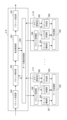
- FIG. 1 is a block diagram showing a configuration example of a data processing system using a data transfer device according to an embodiment of the present invention.
- the data processing system includes user management devices 1-1 to 1-3 for managing information on users who have applied for use of services and for controlling transfer of packets received from users, and one or more data for transferring packets. Transfer devices 2-1 to 2-9, data processing devices 3-1 to 3-13 for performing SF data processing on data contained in received packets, and packets for which all data processing in the service chain has been completed. to the user.
- the data processing system calculates the route of the service chain necessary for realizing the service requested by the user, transmits the route information to the user management devices 1-1 to 1-3, and transfers the data transfer device 2 on the calculated route.
- -1 to 2-9 are provided with a communication management device 5 for updating the routing table based on the result of route calculation.
- the data processing devices 3-1 to 3-13 include CPUs (Central Processing Units), FPGAs (field-programmable gate arrays), GPUs (graphics processing units), ASICs (Application Specific integrated circuits), and the like.
- CPUs Central Processing Units
- FPGAs field-programmable gate arrays
- GPUs graphics processing units
- ASICs Application Specific integrated circuits
- a cloud service customized for each user is provided by combining SF realized by the data processing devices 3-1 to 3-13. Specifically, data transfer devices 2-1 to 2-9 communicate with each other, and transfer data packets sent from users to appropriate SFs. When the data processing in the SF is completed, the data packet is transferred to another SF for data processing.
- a combination of services for realizing the service requested by the user is provided.
- the communication path that data packets follow is called a service chain.
- 14 in FIG. 1 is an example of a service chain. If a service chain is used by multiple users at the same time, data will collide in SF, and proper results cannot be guaranteed. Therefore, in the data processing system of this embodiment, the user management devices 1-1 to 1-3 at the entrance manage data packets and control the service chain so that only one user can use it.
- the user management devices 1-1 to 1-3 also add tags to data packets.
- Route information consisting of a combination of SFs forming a service chain is described in the tag, and the data transfer devices 2-1 to 2-9 refer to the attached tag to perform packet routing. and transfer the packet toward the SF of the target data processing device.
- the external transmission devices 4-1 to 4-3 convert the processed data into IP packets and send them back to the user.
- TCP/IP is used as a global standard for communication outside the data processing system.
- packet communication using tags is performed within the data processing system that performs service chain routing.
- the external transmitters 4-1 to 4-3 are used to absorb protocol differences inside and outside the data processing system.
- the data transfer device of this embodiment refers to the service function number (SF number) of the service function constituting the service chain added to the transfer data of the packet and the identification information (UID) of the service chain to determine the transfer destination of the data. to control.
- the SF number is a unique value assigned to each SF
- the UID is a value for identifying a user's service chain.
- the SF number is used to acquire candidates for the data transfer destination (next hop and output port, which is the nearest transfer destination), and the UID is used to narrow down the transfer destination, thereby determining the packet transfer destination.
- a plurality of UIDs may be collectively defined as a transfer destination.
- a method of grouping UIDs it is conceivable to group them by a common portion of the UIDs, define a default transfer destination for a plurality of UIDs, or the like, but is not limited to these.
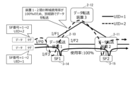
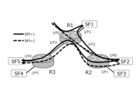
- FIG. 2A is a diagram for explaining the operation of the data transfer device according to the embodiment of the present invention.
- both users' service chains include SF1 and SF2, SF number 1 and SF number 2 are described in the route information (destination information) of the tag of the packet.
- the communication path is changed for each service chain (UID) because the bandwidth between data transfer device 1 and data transfer device 2 is tight. Even if there are service chains that use the same service function, the UID can be used to change the transfer destination for each service chain.
- FIG. 2B is a diagram showing a configuration example of a routing table in the data transfer device according to the embodiment of the present invention.
- a UID that is service chain identification information and a packet forwarding destination information that is the next hop that is the nearest forwarding destination and the number of the port that outputs the packet.
- service chains (UID1, UID2) using the same SF (SF1, SF2) are collectively managed.
- the data transfer device 1 When the data transfer device 1 (2-10) receives a packet whose first SF number is [1], since only the default transfer destination is registered in the routing table, regardless of the UID, from the output port I/F3 Send data to SF1. On the other hand, when a packet with a leading SF number of [2] is received, an output port corresponding to one transfer destination is selected from two transfer destination candidates according to the UID, and the output port is selected from I/F1 or I/F2. Send a packet.
- the SF number is updated in SF1 after data processing, and the SF number of SF1 that performed data processing is deleted.
- the SF number at the beginning of the route information (destination information) added to the packet is changed.
- the data transfer apparatus of this embodiment acquires transfer destination candidates of the packet using the SF number added to the received packet, and determines the transfer destination of the packet based on the identification information of the service chain. Since it is configured as above, it is possible to collectively manage service chains that use the same SF. Therefore, even when the routing table is exhausted, it is possible to route a new service chain that uses a known service function. However, the condition is that the new service chain does not increase the number of forwarding destination candidates.
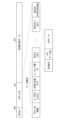
- FIG. 3 is a block diagram showing the configuration of the data transfer device 2-8 and the data processing devices 3-9 and 3-10.
- the data transfer device 2-8 is subordinate to data processing devices 3-9 and 3-10 configured to perform data processing of service functions on data contained in received packets. have.
- the data transfer device 2-8 is composed of a packet reception unit 200, a packet transmission unit 201, a packet analysis unit 202, a transfer control unit 203, and a data communication control unit 204.
- the packet receiving unit 200 receives packets from the user management device or the data transfer device.
- a received packet is attached with a tag including a service function number unique to a service function constituting a service chain and identification information of the service chain.
- the transfer control unit 203 is configured to transfer the received packet to a subordinate data processing device or other data transfer device based on a pre-registered routing table.
- the routing table is registered in advance in the data transfer device on the route of the service chain.
- the transfer control unit 203 acquires transfer destination candidates of the packet using the service function number added to the received packet, and determines the transfer destination of the packet from the transfer destination candidates based on the identification information of the service chain.
- the data processors 3-9 and 3-10 connected under the data transfer device 2-8 each include a packet acquisition unit 300, a data construction unit 301, a data processing unit 302, a register management unit 303, and a packet It is composed of a creation unit 304 and a tag update unit 305 .
- FIG. 4 is a flow chart for explaining the operation of the data transfer method of the data transfer device according to the embodiment of the present invention.
- FIG. 5 is a flow chart for explaining the operation of the data processing device under the data transfer device according to the embodiment of the present invention.
- the packet analyzer 202 analyzes the received packet and extracts the tag header added to the packet. (steps S1-2, S1-3).
- the SF number the leading SF number is acquired from at least one SF number added to the data, and the acquired UID and SF number are transmitted to the transfer control unit 203 together with the received packet.
- the transfer control unit 203 searches the routing table using the obtained SF number and obtains a data transfer destination candidate (step S1-4). Then, the acquired transfer destination candidates and the UID of the received packet are compared (step S1-5). ). If there is no matching UID in the routing table, the default transfer destination corresponding to that SF number is obtained (step S1-6).
- the packet acquisition unit 300 receives a packet from the data transfer device 2-8 (step S2-1), and extracts a payload portion (data to be processed, etc.) from the received packet (step S2-2).
- the tag information attached to the received data packet is sent to the packet creation unit 304 to packetize the processed data.
- the data construction unit 301 of the data processing device 3-9 or 3-10 reconstructs the original data by combining the payloads of the multiple data packets acquired by the packet acquisition unit 300 (step S2-3).
- the data constructing unit 301 performs packet order control, and extracts the processing target data extracted from the plurality of packets. Arrange in the correct order. This packet order control can be performed based on the sequence number included in the tag of the packet.
- the data constructing unit 301 transmits the reconstructed data that can be processed to the data processing unit 302 .
- the data processing unit 302 executes data processing of a predetermined service function on the data received from the data construction unit 301, and transmits the data after completion of the data processing to the packet generation unit 304 (step S2-4).
- the packet generation unit 304 packetizes the data received from the data processing unit 302 using the tag information attached to the received data packet, and transmits the generated packet to the tag update unit 305 (step S2-5). ).
- the tag update unit 305 refers to the route information (destination information) of the SF number included in the tag attached to the packet received from the packet creation unit 304, and the SF (data processing device 3-9 or 3-10) is removed from the route of the service chain (step S2-6), and the packet with the updated route information is transmitted to the data transfer device 2-8. (Step S2-7).
- the register management unit 303 of the data processing device 3-9 or 3-10 acquires parameters from the tag data and registers them in the data processing device. Specifically, the register management unit 303 acquires user-specific parameters necessary for SF processing from the user management device via the tag of the received packet, and registers the acquired parameters in the data processing unit 302 . This parameter can be used when it is desired to change the processing in the data processing unit for each user (for each UID).
- the data processing unit 302 uses a parameter corresponding to the UID acquired by the packet acquisition unit 300 among the parameters registered by the register management unit 303 to execute a predetermined service function on the data received from the data construction unit 301. perform data processing;
- the data transfer device 2-8 When the data transfer device 2-8 receives a processed packet from the data processing device 3-9 or 3-10, the data transfer device 2-8 updates the routing table in the same manner as when the packet is received from the user management device or the data transfer device described above. packet forwarding control based on
- the packet analysis unit 202 receives the data processing device 3-9 or 3- 10 is analyzed, the UID and SF number are acquired from the tag attached to the packet, and the acquired UID and SF number and the received packet are output to the transfer control unit 203 (step S1-2, S1-3).
- the transfer control unit 203 searches the routing table using the SF number in the same manner as when the packet is received from the packet receiving unit 200 described above, and acquires data transfer destination candidates. Then, the transfer destination candidate and the UID of the received data are compared, and if there is a matching UID, the transfer destination (next hop and output port as the nearest transfer destination) is acquired from the transfer destination candidate. Otherwise, get the default destination for that SF number.
- the packet output from the packet analysis unit 202 is sent to the data processing device 3-9 or 3- through the data communication control unit 204 in the same manner as when the packet is received from the packet reception unit 200 described above. 10 or to an adjacent data transfer device via the packet transmission unit 201 .
- the SF number of the data processing device 3-9 or 3-10 that has completed data processing is removed from the route information of the service chain by updating the tag by the tag updating unit 305, so the processing is completed.
- a completed data processing device (SF) is never selected as a transfer destination.
- the data transfer device 2-8 and the data processing devices 3-9 and 3-10 are described as examples, but the data transfer device 2- in FIG. 1 to 2-7 and 2-9 have the same configuration and operation as the data transfer device 2-8. It is similar to devices 3-9 and 3-10.
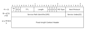
- FIG. 6 is a diagram showing a configuration example of a data structure in the data transfer device according to the embodiment of the present invention.
- Transfer data transferred within the service function chaining system according to the embodiment of the present invention consists of a tag header 407 including protocol information, data attributes, and destination information (route information) and processing target data 403 to be processed. Can be configured.
- information related to data discarding such as TTL (Time to Live) and header checksum
- information related to tag header configuration such as data type and header length
- a UID for identifying a service chain can be set in the data attribute of the tag header 407.
- SF recognizes the delimiter of the data to be processed. You can set a sequence number that will be used to rearrange to the correct order when the order is changed.
- At least one destination information is included as service chain route information.
- the service function numbers (SF numbers) of the destinations forming the service chain are arranged in the order of data processing in the service chain.
- metadata directed to the SF can be set in the destination information. By setting the metadata length in the destination information, metadata of any length can be set.
- Metadata is to register or update the parameters of the data processing device (SF) by the register management unit 303 described in FIG.
- SF data processing device
- parameters can be registered in each SF according to the service chain by setting the parameters in the metadata of the destination information.
- the SF can determine whether the data is data to be processed or a parameter based on the data type of the protocol information in the tag header.
- the above data may be encapsulated in an Ethernet frame as shown in the configuration example of FIG.
- multiple SFs can be connected to one port of the data transfer device, and connections exceeding the number of output ports of the data transfer device can be realized.
- the data transfer devices 2-1 to 2-9 and the data processing devices 3-1 to 3-13 described in this embodiment are a computer having a CPU (or GPU), a storage device and an interface, and these hardware. It can be implemented by a program that controls resources.
- the computer comprises a CPU 500 (or GPU), a storage device 501 and an interface device 502 .
- a program for implementing the data processing method of the present invention is stored in the storage device 501 .
- the CPU 500 (or GPU) of each device executes the processing described in this embodiment according to the programs stored in the storage device 501 .
- At least part of the data transfer devices 2-1 to 2-9, data processing devices 3-1 to 3-13, user management devices 1-1 to 1-3, and external transmission devices 4-1 to 4-3 are FPGAs or It may be configured by ASIC.
- an improvement in processing performance can be expected by executing part of the packet processing and data processing by these hardware.
- the data transfer apparatus of this embodiment acquires transfer destination candidates of the packet using the service function number added to the received packet, and determines the transfer destination of the packet based on the identification information of the service chain. Therefore, service chains that use the same service function can be collectively managed. Therefore, even when the routing table is exhausted, it is possible to route a new service chain that uses a known service function.
- the data transfer device of the present invention has at least one data processing device configured to perform data processing of a service function on data contained in a received packet.
- a packet receiver for receiving a packet having a tag including a service function number unique to the service function constituting a service chain for realizing a service and identification information of the service chain;
- a transfer control unit that transfers a received packet to the data processing device or another data transfer device under its control based on a routing table registered in the data transfer device, wherein the transfer control unit controls the transmission of the received packet;
- a transfer destination candidate of the packet is obtained from the routing table using the service function number included in the tag, and the transfer destination of the packet is determined based on the identification information of the service chain.
- the routing table associates the service chain identification information with packet forwarding destination information for each service function number unique to the service function. Registered.
- the packet includes process target data to be subjected to the data processing and route information of the service chain including at least one of the service function numbers. and the tag containing the identification information of the service chain, wherein the tag is a flag for the service function to recognize the delimiter of the data to be processed, and the tag is used when the order of the data to be processed is changed
- the route information includes a sequence number for rearranging the data to be processed in the correct order, and the route information arranges the service function numbers in the order of the data processing in the service chain.
- At least one data processing device configured to perform data processing of a service function on data contained in a received packet is subordinated and registered
- the step of acquiring the transfer destination information is performed when the data processing is completed in the data processing device when the received packet is transferred to the data processing device under control. Using the updated service function number information of the packet, the transfer destination of the packet is determined.
- the routing table associates the identification information of the service chain and the forwarding destination information of the packet for each service function number unique to the service function. Registered.
- the packet includes process target data to be subjected to the data processing and route information of the service chain including at least one of the service function numbers. and the tag including the identification information of the service chain, wherein the tag includes a flag for the service function to recognize the delimiter of the data to be processed, and the tag to indicate when the order of the data to be processed is changed.
- the route information includes a sequence number for rearranging the data to be processed in the correct order, and the route information arranges the service function numbers in the order of the data processing in the service chain.
- the present invention can be applied to service function chaining technology.
Landscapes
- Engineering & Computer Science (AREA)
- Computer Networks & Wireless Communication (AREA)
- Signal Processing (AREA)
- Computer Security & Cryptography (AREA)
- Data Exchanges In Wide-Area Networks (AREA)
Abstract
Description
図1は、本願発明の実施の形態に係るデータ転送装置を用いたデータ処理システムの構成例を示すブロック図である。データ処理システムは、サービスの利用を申請したユーザの情報の管理とユーザから受信したパケットの転送制御とを行うユーザ管理装置1-1~1-3と、パケットの転送を行う1乃至複数のデータ転送装置2-1~2-9と、受信したパケットに含まれるデータに対してSFのデータ処理を行うデータ処理装置3-1~3-13と、サービスチェインの全てのデータ処理が完了したパケットをユーザ宛に返送する外部送信装置4-1~4-3とを備えている。
本実施の形態のデータ転送装置は、パケットの転送データに付加されたサービスチェインを構成するサービス機能のサービス機能番号(SF番号)とサービスチェインの識別情報(UID)を参照してデータの転送先を制御する。SF番号は、各SFに割り当てたユニークな値であり、UIDは、ユーザのサービスチェインを識別するための値である。
図3はデータ転送装置2-8とデータ処理装置3-9、3-10の構成を示すブロック図である。図3の構成例では、データ転送装置2-8は、受信したパケットに含まれるデータに対してサービス機能のデータ処理を行うように構成されたデータ処理装置3-9、3-10を配下に有している。
図4は、本願発明の実施の形態に係るデータ転送装置のデータ転送方法の動作を説明するためのフローチャートである。図5は、本願発明の実施の形態に係るデータ転送装置の配下のデータ処理装置の動作を説明するためのフローチャートである。
図6は、本願発明の実施の形態に係るデータ転送装置におけるデータ構造の構成例を示す図である。本願発明の実施の形態に係るサービスファンクションチェイニングシステム内で転送される転送データは、プロトコル情報、データ属性、宛先情報(ルート情報)を含むタグヘッダ407とデータ処理の対象となる処理対象データ403で構成することができる。
Claims (8)
- 受信したパケットに含まれるデータに対してサービス機能のデータ処理を行うように構成された少なくとも1つのデータ処理装置を配下に有し、
ユーザが要求するサービスを実現するためのサービスチェインを構成する前記サービス機能に固有のサービス機能番号と、前記サービスチェインの識別情報とを含むタグを有するパケットを受信するパケット受信部と、
前記サービスチェインのルート上のデータ転送装置に登録されているルーティングテーブルに基づいて、受信したパケットを配下の前記データ処理装置または他のデータ転送装置に転送する転送制御部と
を備え、
前記転送制御部は、受信したパケットの前記タグに含まれる前記サービス機能番号を用いて前記ルーティングテーブルからパケットの転送先候補を取得し、前記サービスチェインの前記識別情報に基づいて前記パケットの転送先を決定する
データ転送装置。 - 前記転送制御部は、
受信したパケットを配下の前記データ処理装置に転送した場合に、前記データ処理装置においてデータ処理が完了したパケットの更新された前記サービス機能番号の情報を用いて、前記パケットの転送先を決定する
請求項1記載のデータ転送装置。 - 前記ルーティングテーブルは、
前記サービス機能に固有のサービス機能番号毎に、前記サービスチェインの識別情報と、パケットの転送先情報とが関連付けて登録されている
請求項1または2に記載のデータ転送装置。 - 前記パケットは、
前記データ処理の対象となる処理対象データと、少なくとも1つの前記サービス機能番号を含む前記サービスチェインのルート情報と、前記サービスチェインの識別情報を含む前記タグを含み、
前記タグは、
前記サービス機能が前記処理対象データの区切りを認識するためのフラグと、前記処理対象データの順番が入れ替わった場合に、前記処理対象データを正しい順番に並び替えるためのシーケンス番号を含み、
前記ルート情報は、
前記サービス機能番号が、前記サービスチェインにおける前記データ処理の順番に配置されている
請求項1から3の何れか1項に記載のデータ転送装置。 - 受信したパケットに含まれるデータに対してサービス機能のデータ処理を行うように構成された少なくとも1つのデータ処理装置を配下に有し、登録されているルーティングテーブルに基づいて、受信したパケットを配下の前記データ処理装置または他のデータ転送装置に転送するデータ転送装置におけるデータ転送方法であって、
サービスチェインを構成する前記サービス機能に固有のサービス機能番号と前記サービスチェインの識別情報を含むタグを有するパケットを受信するステップと、
受信したパケットの前記タグから前記サービスチェインの前記識別情報と前記サービス機能番号を取得するステップと、
前記サービス機能番号を用いて前記ルーティングテーブルを検索し、前記パケットの転送先候補を取得するステップと、
前記転送先候補と前記サービスチェインの識別情報を比較し、前記サービスチェインの識別情報が一致する転送先候補がある場合には、その転送先候補から転送先情報を取得するステップと、
取得した前記転送先情報に基づいてパケットを出力するステップと
を含むデータ転送方法。 - 前記転送先情報を取得するステップは、
受信したパケットを配下の前記データ処理装置に転送した場合に、前記データ処理装置においてデータ処理が完了したパケットの更新された前記サービス機能番号の情報を用いて、前記パケットの転送先を決定する
請求項5記載のデータ転送方法。 - 前記ルーティングテーブルは、
前記サービス機能に固有のサービス機能番号毎に、前記サービスチェインの識別情報と、パケットの転送先情報とが関連付けて登録されている
請求項5または6に記載のデータ転送方法。 - 前記パケットは、
前記データ処理の対象となる処理対象データと、少なくとも1つの前記サービス機能番号を含む前記サービスチェインのルート情報と、前記サービスチェインの識別情報を含む前記タグを含み、
前記タグは、
前記サービス機能が前記処理対象データの区切りを認識するためのフラグと、前記処理対象データの順番が入れ替わった場合に、前記処理対象データを正しい順番に並び替えるためのシーケンス番号を含み、
前記ルート情報は、
前記サービス機能番号が、前記サービスチェインにおける前記データ処理の順番に配置されている
請求項5から7の何れか1項に記載のデータ転送方法。
Priority Applications (1)
| Application Number | Priority Date | Filing Date | Title |
|---|---|---|---|
| US18/705,352 US20250227062A1 (en) | 2021-11-12 | 2022-11-08 | Data transfer device and data transfer method |
Applications Claiming Priority (2)
| Application Number | Priority Date | Filing Date | Title |
|---|---|---|---|
| JP2021-184730 | 2021-11-12 | ||
| JP2021184730A JP7676294B2 (ja) | 2021-11-12 | 2021-11-12 | データ転送装置およびデータ転送方法 |
Publications (1)
| Publication Number | Publication Date |
|---|---|
| WO2023085267A1 true WO2023085267A1 (ja) | 2023-05-19 |
Family
ID=86335740
Family Applications (1)
| Application Number | Title | Priority Date | Filing Date |
|---|---|---|---|
| PCT/JP2022/041555 Ceased WO2023085267A1 (ja) | 2021-11-12 | 2022-11-08 | データ転送装置およびデータ転送方法 |
Country Status (3)
| Country | Link |
|---|---|
| US (1) | US20250227062A1 (ja) |
| JP (1) | JP7676294B2 (ja) |
| WO (1) | WO2023085267A1 (ja) |
Family Cites Families (2)
| Publication number | Priority date | Publication date | Assignee | Title |
|---|---|---|---|---|
| US9967175B2 (en) * | 2014-02-14 | 2018-05-08 | Futurewei Technologies, Inc. | Restoring service functions after changing a service chain instance path |
| US9979645B2 (en) * | 2015-01-14 | 2018-05-22 | Futurewei Technologies, Inc. | Hardware and software methodologies for creating and managing portable service function chains |
-
2021
- 2021-11-12 JP JP2021184730A patent/JP7676294B2/ja active Active
-
2022
- 2022-11-08 US US18/705,352 patent/US20250227062A1/en active Pending
- 2022-11-08 WO PCT/JP2022/041555 patent/WO2023085267A1/ja not_active Ceased
Non-Patent Citations (2)
| Title |
|---|
| FUKUOKA, AKI: "A Service Chain Routing Method under Virtualized CPE/SGW Environments", PROCEEDINGS OF THE 2016 IEICE GENERAL CONFERENCE COMMUNICATION 2; MARCH 15-18, 2016, IEICE, JP, 1 March 2016 (2016-03-01) - 18 March 2016 (2016-03-18), JP, pages 51, XP009545616 * |
| KONOMI MOCHIZUKI, SHUNSUKE HOMMA, KOJI SUGISONO, HIROFUMI YAMAZAKI, TOSHINORI KIKUCHI, AKEO MASUDA, KENGO NAITO, HIROYUKI KITADA, : "Service Chaining Method to Satisfy the Carrier Requirements for Network Functions Virtualization", IEICE TECHNICAL REPORT, NS, IEICE, JP, vol. 114, no. 206 (NS2014-98), 4 September 2014 (2014-09-04), JP, pages 113 - 118, XP009545606 * |
Also Published As
| Publication number | Publication date |
|---|---|
| JP7676294B2 (ja) | 2025-05-14 |
| US20250227062A1 (en) | 2025-07-10 |
| JP2023072287A (ja) | 2023-05-24 |
Similar Documents
| Publication | Publication Date | Title |
|---|---|---|
| US10887220B2 (en) | Application identifier in service function chain metadata | |
| US8873563B2 (en) | Techniques for next-hop optimization | |
| US7420979B2 (en) | VLAN server | |
| US9270566B2 (en) | Monitoring server load balancing | |
| US11909668B2 (en) | Programmable packet data processing system | |
| US9450870B2 (en) | System and method for flow management in software-defined networks | |
| CN111107001B (zh) | 网络中分段源路由的方法及存储介质 | |
| CN107786437B (zh) | 报文转发方法及装置 | |
| US20130286844A1 (en) | Information system, control apparatus, communication method, and program | |
| JP2006506858A (ja) | 多数の論理サブ送信システムの機能性を持つ送信システム | |
| JP6544401B2 (ja) | パケット転送装置、制御装置、通信システム、通信方法及びプログラム | |
| US10498669B2 (en) | Communication system, switch, controller, ancillary data management apparatus, data forwarding method, and program | |
| JP5888338B2 (ja) | 通信システムおよび通信方法 | |
| WO2015125804A1 (ja) | 通信システム、制御装置、通信制御方法、および、プログラム | |
| EP3518113B1 (en) | Transfer device for a content distribution system | |
| US9385951B2 (en) | Apparatus and method for controlling packet transfer based on registered destination information | |
| JP7676294B2 (ja) | データ転送装置およびデータ転送方法 | |
| JP7789529B2 (ja) | データ処理システムおよびデータ処理方法 | |
| US12388676B2 (en) | Data transfer device, data processing device and data processing method | |
| US20130188647A1 (en) | Computer system fabric switch having a blind route | |
| WO2017207039A1 (en) | Software defined networking system for distiguishing packet-in messages | |
| JP2003188936A (ja) | パケット処理装置とそのパケット転送方法 | |
| CN103098431B (zh) | 计算机系统结构交换机 | |
| US10715440B1 (en) | Distributed next hop resolution | |
| JP2026034958A (ja) | データ処理装置、およびデータ処理方法 |
Legal Events
| Date | Code | Title | Description |
|---|---|---|---|
| 121 | Ep: the epo has been informed by wipo that ep was designated in this application |
Ref document number: 22892765 Country of ref document: EP Kind code of ref document: A1 |
|
| WWE | Wipo information: entry into national phase |
Ref document number: 18705352 Country of ref document: US |
|
| NENP | Non-entry into the national phase |
Ref country code: DE |
|
| 122 | Ep: pct application non-entry in european phase |
Ref document number: 22892765 Country of ref document: EP Kind code of ref document: A1 |
|
| WWP | Wipo information: published in national office |
Ref document number: 18705352 Country of ref document: US |