WO2023085254A1 - Vehicle antenna device - Google Patents
Vehicle antenna device Download PDFInfo
- Publication number
- WO2023085254A1 WO2023085254A1 PCT/JP2022/041507 JP2022041507W WO2023085254A1 WO 2023085254 A1 WO2023085254 A1 WO 2023085254A1 JP 2022041507 W JP2022041507 W JP 2022041507W WO 2023085254 A1 WO2023085254 A1 WO 2023085254A1
- Authority
- WO
- WIPO (PCT)
- Prior art keywords
- conductive film
- antenna
- main surface
- vehicle
- film
- Prior art date
Links
Images


Classifications
-
- B—PERFORMING OPERATIONS; TRANSPORTING
- B60—VEHICLES IN GENERAL
- B60J—WINDOWS, WINDSCREENS, NON-FIXED ROOFS, DOORS, OR SIMILAR DEVICES FOR VEHICLES; REMOVABLE EXTERNAL PROTECTIVE COVERINGS SPECIALLY ADAPTED FOR VEHICLES
- B60J1/00—Windows; Windscreens; Accessories therefor
-
- H—ELECTRICITY
- H01—ELECTRIC ELEMENTS
- H01P—WAVEGUIDES; RESONATORS, LINES, OR OTHER DEVICES OF THE WAVEGUIDE TYPE
- H01P5/00—Coupling devices of the waveguide type
- H01P5/02—Coupling devices of the waveguide type with invariable factor of coupling
-
- H—ELECTRICITY
- H01—ELECTRIC ELEMENTS
- H01Q—ANTENNAS, i.e. RADIO AERIALS
- H01Q1/00—Details of, or arrangements associated with, antennas
- H01Q1/27—Adaptation for use in or on movable bodies
- H01Q1/32—Adaptation for use in or on road or rail vehicles
-
- H—ELECTRICITY
- H01—ELECTRIC ELEMENTS
- H01Q—ANTENNAS, i.e. RADIO AERIALS
- H01Q21/00—Antenna arrays or systems
- H01Q21/28—Combinations of substantially independent non-interacting antenna units or systems
Definitions
- the present invention relates to a vehicle antenna device.
- This application claims priority based on Japanese Patent Application No. 2021-184698 filed in Japan on November 12, 2021, the content of which is incorporated herein.
- conductive films such as Low-E and heat ray reflective films, and light control films that can electrically (actively) change the visible light transmittance. or provide thermal/optical added value.
- a conductive film when a conductive film is coated on a dielectric such as glass, it can be used as a glass antenna that receives a predetermined broadcast wave by arranging a wire conductor pattern on the vehicle window glass like a conventional vehicle window glass. desired antenna gain is not obtained.
- Japanese Patent Laid-Open No. 2002-200003 is known as a technique that uses a conductive film coating as an antenna.
- an antenna element including a conductive film that is heated by applying a voltage between a pair of bus bars is used for terrestrial digital television broadcast waves, DAB (Digital Audio Broadcast) broadcast waves, and FM broadcast waves. It is described that it functions as an antenna that can receive Further, in Patent Document 1, by providing a grid portion of a region in which the conductor portion of the conductive film is removed and the resistance thereof is increased, the antenna can function as an antenna capable of receiving AM broadcast waves.
- the present invention provides a vehicle antenna device that can easily receive AM broadcast waves using a conductive film in a vehicle window glass using a conductive film.
- a vehicle antenna device includes a dielectric substrate having a first main surface and a second main surface, and a dielectric substrate provided on the second main surface side, the area of the dielectric substrate in plan view being a conductive film that is 0.025 m 2 or more.
- the conductive film has a sheet resistance value of 1.5 ⁇ 10 3 ⁇ / ⁇ or less, and can receive AM broadcast waves from a feeding point electrically connected to the conductive film.
- the feeding point is arranged in a central portion of the conductive film, which is separated from an edge of the dielectric substrate by 150 mm or more in plan view of the dielectric substrate. good too.
- the outer edge of the conductive film may be substantially quadrangular in plan view of the dielectric substrate.
- the feeding point electrically connected to the conductive film is a first feeding point, provided on the first main surface side, and having VHF band and UHF band an antenna for receiving radio waves of at least one of the frequencies of; an antenna electrode arranged inside an outer edge of a pore region inside the conductive film in a plan view of the dielectric substrate; and connected to the antenna.
- the antenna conductor may be electrically connected to the antenna electrode, and may be capable of receiving radio waves of at least one of VHF band and UHF band frequencies by a signal received using the antenna electrode as a second feeding point.
- the antenna conductor and the antenna electrode may be electrically connected by capacitive coupling.
- the antenna conductor and the antenna electrode may be directly connected by a connection conductor arranged in a through hole of the dielectric substrate.
- the dielectric substrate is a first dielectric substrate, and the second main surface side of the first dielectric substrate has a dielectric parallel to the second main surface. and an intermediate film disposed between the first dielectric substrate and the second dielectric substrate.
- the second dielectric substrate has a third main surface on the side of the first dielectric substrate and a fourth main surface on the side opposite to the third main surface, and the conductive film has the third main surface.
- the antenna electrode may be arranged between the first dielectric substrate and the second dielectric substrate, and the antenna electrode may be arranged on the fourth main surface side.
- the conductive film may be arranged in contact with the second main surface.
- the intermediate film includes a first intermediate film and a second intermediate film
- the conductive film includes the first intermediate film and the second intermediate film. may be sandwiched between
- the conductive film may be a light control film containing a conductor.
- the conductive film may be arranged in contact with the third main surface or the fourth main surface.
- the intermediate film includes a first intermediate film and a second intermediate film
- the conductive film includes a first conductive film and a second conductive film.
- the first conductive film and the second conductive film are located on the second main surface, between the first intermediate film and the second intermediate film, and on the third main surface and a position on the fourth main surface, and are arranged in order from the one closest to the first dielectric substrate, and the second conductive film is located on the plane of the first dielectric substrate.
- it may have a second pore region arranged so as to overlap with the first pore region which is the pore region of the first conductive film.
- the first conductive film is arranged in contact with the second main surface, and the second conductive film is formed of the first intermediate film and the second intermediate film. may be sandwiched between
- the first conductive film may be a conductor for reflecting heat rays
- the second conductive film may be a light control film including a conductor
- the conductive film includes a third conductive film disposed in contact with the fourth main surface, and the third conductive film is for a low emissivity film. conductor.
- the first conductive film is sandwiched between the first intermediate film and the second intermediate film, and the second conductive film It may be placed in contact with the surface.
- the first conductive film may be a light control film containing a conductor
- the second conductive film may be a conductor for a low emissivity film.
- the antenna is capable of receiving the frequency of FM broadcast waves, includes an AM amplifier and an FM amplifier, and the signal in the frequency band of AM broadcast waves is the first A signal in a frequency band of an FM broadcast wave may be input from a feeding point to the AM amplifier and input to the FM amplifier from the second feeding point.
- the filter may be a capacitor, and the capacitor may have a capacity of 5 pF to 150 pF.
- the antenna may be surrounded by a cover member projecting outward from the first main surface side of the dielectric substrate.
- the dielectric substrate may be a glass substrate.
- the dielectric substrate may be attached to the roof of the vehicle in parallel with the horizontal plane of the vehicle.
- the vehicle antenna device can easily receive AM broadcast waves using the conductive film in the vehicle window glass using the conductive film.
- BRIEF DESCRIPTION OF THE DRAWINGS It is a perspective view which shows typically an example of the vehicle antenna apparatus of 1st Embodiment. BRIEF DESCRIPTION OF THE DRAWINGS It is sectional drawing which shows an example of the vehicle antenna apparatus of 1st Embodiment. BRIEF DESCRIPTION OF THE DRAWINGS It is a block diagram by the planar view which shows an example of the vehicle glass of 1st Embodiment. BRIEF DESCRIPTION OF THE DRAWINGS It is a block diagram by the planar view which shows an example of the vehicle glass of 1st Embodiment.
- FIG. 12 is a cross-sectional view showing an example of a vehicle antenna device according to an eighth embodiment
- the member A is present, but also the case where the member A is arranged so as to be separated from the main surface. Moreover, when the main surface and the member A are spaced apart, there may or may not be an intervening material between the main surface and the member A.
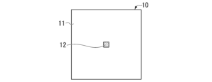
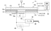
- FIG. 1 is a perspective view schematically showing an example of the vehicle antenna device 1 of the first embodiment.
- FIG. 2 is a cross-sectional view showing an example of the vehicle antenna device 1 of this embodiment.
- the cross-sectional view shown in FIG. 2 is a cross-sectional view taken along line AB of area AR1 in FIG.
- the vehicle antenna device 1 uses vehicle glass 10 .
- a vehicle antenna device 1 includes a vehicle glass 10 , an antenna section 20 , an amplifier section 30 and a filter 40 .
- Filter 40 may be a high-pass filter or a band-stop filter. Hereinafter, unless otherwise specified, the high-pass filter 40 will be described.
- the vehicle glass 10 is, for example, roof glass attached to the roof of the vehicle.
- the vehicle glass 10 is attached to the roof of the vehicle parallel (including substantially parallel) to the horizontal plane of the vehicle.
- a configuration example of the vehicle glass 10 will be described with reference to FIG. 2 .
- the vehicle glass 10 is, for example, a single plate glass.
- the vehicle glass 10 includes a glass substrate 11 , an antenna conductor 12 , a conductive film 13 , an antenna electrode 15 , a feeding point 16 and a shielding layer 17 .
- the shape of the vehicle glass 10 may be a curved shape or a planar shape (non-curved shape). Further, the vehicle glass 10 may have, for example, a single-curved shape curved in one of the vertical and horizontal directions (with respect to one side of the frame) when mounted on a vehicle.
- the vehicle glass 10 may have a compound curved shape that is curved both vertically and horizontally. Note that the single-curved shape may be a shape curved in only one arbitrary direction.
- a compound curved shape may be a shape curved in any two or more different directions.
- the minimum value of the radius of curvature of the vehicle glass 10 is preferably 500 mm or more and 100000 mm or less.
- the glass substrate 11 is an example of a dielectric substrate and has a first main surface F1 and a second main surface F2.
- the main surface of the glass substrate 11 on the outside of the vehicle is the first main surface F1.
- the main surface opposite to the first main surface F1 side is the second main surface F2.
- the antenna conductor 12 is an electrode connected to the antenna 21, and is arranged on the first main surface F1 side.
- the antenna conductor 12 is formed, for example, on the first main surface F1 side of the glass substrate 11 so as to be in contact with the glass substrate 11 (on the glass substrate 11).
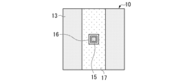
- FIGS. 3A to 3C are plan views of the antenna conductor 12 viewed from outside the vehicle.
- FIG. 3A to 3C are configuration diagrams in plan view showing an example of the vehicle glass 10 of the present embodiment.
- FIG. 3A is a plan view of the vehicle glass 10 as viewed from the outside of the vehicle (first main surface F1).
- the antenna conductor 12 is arranged as a square electrode in the central portion of the first main surface F1 of the glass substrate 11, as shown in FIG. 3A. That is, the antenna conductor 12 is formed in a rectangular shape (including a substantially rectangular shape) in a plan view of the glass substrate 11 .
- the conductive film 13 includes, for example, a conductive film for heat reflection (heat ray reflective film), a conductive film for low radiation (Low-E (Low Emissivity) coating, which coats the vehicle glass 10).
- a typical example of the heat ray reflective film is a metal film, and examples of the metal film include silver (Ag).
- a low-emissivity film such as a Low-E film secures heat insulation by suppressing heat transfer by radiation.
- the Low-E film may be, for example, a laminated film including a transparent dielectric film, an infrared reflective film, and a transparent dielectric film in this order.
- Typical transparent dielectric films are metal oxides and metal nitrides, and typical metal oxides are zinc oxide and tin oxide.
- the conductive film 13 is provided on the second main surface F2 side with respect to the glass substrate 11 .
- the area of the glass substrate 11 in plan view is preferably 0.025 m 2 or more, more preferably 0.050 m 2 or more, and more preferably 0.100 m 2 or more. More preferably, it is 0.250 m 2 or more, and particularly preferably 0.500 m 2 .
- the outer edge of the conductive film 13 is, for example, substantially rectangular in plan view of the glass substrate 11 in accordance with the shape of the glass substrate 11 .
- the conductive film 13 functions as an AM antenna and as an antenna ground for the antenna 21 .
- the conductive film 13 preferably has a sheet resistance value of 1.5 ⁇ 10 3 ⁇ / ⁇ (ohm/square) or less.
- the sheet resistance value of the conductive film 13 is more preferably 1.0 ⁇ 10 3 ⁇ / ⁇ or less, further preferably 500 ⁇ / ⁇ or less, particularly preferably 300 ⁇ / ⁇ or less, and most preferably 200 ⁇ / ⁇ or less.
- the conductive film 13 has a void region VA inside when the glass substrate 11 is viewed from above.
- the void area VA is arranged so as not to overlap the antenna conductor 12 and the antenna electrode 15 in the thickness direction of the vehicle glass 10 . Further, as shown in FIG. 3B, the void regions VA are arranged as square void regions in plan view of the glass substrate 11 . That is, the void area VA is formed in a rectangular shape (including a substantially rectangular shape) in a plan view of the glass substrate 11 .
- the antenna electrode 15 is arranged on the second main surface F2 side inside the outer edge of the hole area VA in plan view of the glass substrate 11, and is electrically connected to the antenna conductor 12. be done.
- the antenna electrode 15 is arranged, for example, in contact with the second main surface F2 of the glass substrate 11 .
- the antenna electrode 15 and the antenna conductor 12 sandwich the glass substrate 11 .
- the antenna electrode 15 is formed on the opposite side of the glass substrate 11 from the antenna conductor 12 .
- the antenna conductor 12 and the antenna electrode 15 are arranged so as to be capacitively coupled.
- the distance between the antenna conductor 12 and the antenna electrode 15 is approximately 5 mm.
- the distance of the dielectric between the conductors may be less than 30 mm, preferably 20 mm or less, more preferably 10 mm or less.
- the thickness of the vehicle glass 10 is typically about 2 mm to 5 mm including the laminated glass described later. is. Thus, if the thickness of the vehicle glass 10 is less than 30 mm, capacitive coupling between the antenna conductor 12 and the antenna electrode 15 becomes possible, and the circuit can be configured such that the signal received by the antenna 21 is amplified by the amplifier section 30. .
- the shielding layer 17 is arranged on the side of the conductive film 13 opposite to the glass substrate 11 .
- the shielding layer 17 has a pore region whose outer edge is arranged outside the outer edge of the pore region VA of the conductive film 13 .
- the shielding layer 17 is arranged on the conductive film 13 so that the feeding point 16 is exposed.
- the shielding layer 17 shields visible light.
- the shielding layer 17 is an opaque colored ceramic layer.
- the color of the shielding layer 17 is arbitrarily selected.
- the color of the shielding layer 17 is preferably a dark color such as black, brown, gray, dark blue, or white, and more preferably black.
- the hole regions of the shielding layer 17 are formed in a rectangular shape (including a substantially rectangular shape) in a plan view of the glass substrate 11, similarly to the hole regions VA.
- the arrangement of the shielding layer 17 is arbitrarily selected. Also, the shielding layer 17 may be omitted. Furthermore, when the shielding layer 17 is arranged, the shielding layer 17 may be formed in a state in which the shielding layer 17 does not have a void region, that is, the shielding layer 17 may be formed in a so-called “solid shape”. In that case, the shielding layer 17 may be formed (solidly) on the second main surface F2 of the glass substrate 11 . The reason for this is that since the thickness of the shielding layer 17 is about 5 ⁇ m to 25 ⁇ m, even if a structure in which the shielding layer 17 is interposed is adopted, the change in the coupling capacitance between the antenna conductor 12 and the antenna electrode 15 is small.
- the vehicle antenna device 1 is described as having the shielding layer 17 having a hole region.
- the feeding point 16 is an exposed portion where the conductive film 13 is exposed.
- the feeding point 16 is electrically connected to the conductive film 13 .
- the vehicle antenna device 1 can receive AM broadcast waves from the feeding point 16 .
- the feeding point 16 is arranged in the central portion of the conductive film 13 150 mm or more inwardly away from the edge of the glass substrate 11 in plan view of the glass substrate 11 . Note that even if the shielding layer 17 is formed in a solid shape with no void regions as described above, the feeding points 16 may be electrically connected by capacitive coupling.
- the feeding point 16 is preferably spaced inward from the edge of the glass substrate 11 by 200 mm or more, and more preferably spaced inward from the edge of the glass substrate 11 by 300 mm or more.
- FIG. 3C is a plan view of the vehicle glass 10 as seen from the inside of the vehicle (the side of the second main surface F2).
- the antenna electrode 15 is formed in a rectangular shape (including a substantially rectangular shape) in plan view of the glass substrate 11 .
- the antenna electrode 15 is arranged on the second main surface F2 side and formed in a square shape.
- the feeding point 16 is formed in a square loop shape when the glass substrate 11 is viewed from above. That is, the shape of each of the outer edge and the inner edge of the feeding point 16 is square. It should be noted that the loop shape may be a closed loop that is connected over one round, or a shape having one or more cutouts. When the feeding point 16 has a notch, the length of the notch may be, for example, 40 or less, 30 or less, or 20 or less, when the length of one round in the closed loop is normalized to "100". good. Moreover, the length of the notch portion based on the above standardization may be, for example, 1 or more, 2 or more, or 5 or more.
- the feeding point 16 is an example of a first feeding point for receiving AM broadcast waves
- the antenna electrode 15 is an example of a second feeding point for receiving FM broadcast waves.
- the antenna section 20 includes an antenna 21 and an antenna cover 22 .
- the antenna 21 is, for example, an antenna for receiving the frequency band of FM broadcast waves, an antenna for receiving the frequency band of DAB (Digital Audio Broadcast) broadcast waves, and an antenna for receiving the frequency band of terrestrial digital television broadcast waves.
- GNSS Global Navigation Satellite System
- SDARS Setellite Digital Audio Radio Service
- the frequency band of FM broadcast waves (hereinafter referred to as “FM band”) is from 76 MHz (megahertz) to 108 MHz
- the frequency band of DAB Band III broadcast waves (hereinafter referred to as “DAB band”) is from 174 MHz It is 240MHz.
- the frequency band of terrestrial digital television broadcasting waves (hereinafter referred to as “DTV band”) is 470 MHz to 710 MHz.
- the antenna 21 may be capable of receiving a plurality of frequency bands among the FM broadcast wave frequency band, the DAB broadcast wave frequency band, the terrestrial digital television broadcast wave frequency band, the GNSS frequency band, and the SDARS frequency band.
- the antenna 21 is arranged outside the vehicle glass 10 and connected to the antenna conductor 12 .
- the antenna cover 22 (cover member) is a projecting cover grounded on the roof of the vehicle.
- the antenna cover 22 houses the antenna 21 inside.
- the antenna cover 22 is, for example, a shark fin antenna cover.
- the amplifier unit 30 amplifies the received signal of AM broadcast waves received by the conductive film 13 as an AM antenna and the received signal of FM broadcast waves received by the antenna 21, and outputs the amplified signals to, for example, a receiver.
- An input terminal for AM broadcast waves of amplifier section 30 is connected to feeding point 16 , and an input terminal for FM broadcast waves is connected to antenna electrode 15 .
- the output of the amplifier section 30 is supplied to a receiver via a transmission line such as a coaxial cable CB. Details of the amplifier unit 30 will be described later.
- the high-pass filter 40 is arranged between the conductive film 13 and the ground, which is the vehicle body (ground conductor). Between the conductive film 13 and the vehicle body, the high-pass filter 40 passes signals in at least one of the VHF band and UHF band frequencies, and cuts off signals in the AM broadcast wave frequency band. That is, the high-pass filter 40 grounds the conductive film 13 with respect to the vehicle body in the VHF band or higher, and makes the conductive film 13 electrically floating (high impedance state) in the AM band.
- High-pass filter 40 is, for example, capacitor C1.
- the capacitance of the capacitor C1 is preferably 5 pF to 150 pF, more preferably 5 pF to 100 pF.
- the capacitor C1 is a capacitor element connected between the conductive film 13 and the vehicle body. Note that the capacitor C ⁇ b>1 may be located inside the amplifier section 30 .
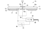
- FIG. 4 is a diagram showing an equivalent circuit of the vehicle antenna device 1 of this embodiment.
- the amplifier section 30 includes an AM amplifier 31 , an FM amplifier 32 and a signal mixer 33 .
- the conductive film 13 functions as an AM antenna and as an antenna ground for the antenna 21 .
- the conductive film 13 is connected to the ground of the amplifier section 30 and the signal ground of the output signal via the capacitor C1 in at least one of the VHF band and the UHF band.
- the ground of the amplifier section 30 and the signal ground of the output signal are connected to the vehicle body BD.
- the capacitance between the vehicle body BD and the conductive film 13 is assumed to be antenna capacitance (C3).
- the conductive film 13 is connected to the input signal line of the AM amplifier 31 through the feeding point 16 .
- a reception signal received by the conductive film 13 as an AM antenna is inputted to the AM amplifier 31 as an input signal. Further, the conductive film 13 is electrically cut off from the ground of the amplifier section 30 and the signal ground of the output signal by the capacitor C1 in the AM broadcast wave frequency band.
- Capacitor C2 is an electrostatic capacitance formed by antenna conductor 12 to which antenna 21 is connected and antenna electrode 15 .
- the capacitor C2 electrically connects the antenna conductor 12 and the antenna electrode 15 by capacitive coupling.
- a reception signal received by the antenna 21 is input to the FM amplifier 32 as an input signal by capacitive coupling of the capacitor C2.
- the AM amplifier 31 amplifies the reception signal of the AM broadcast wave received by the conductive film 13 and outputs the amplified signal to the signal mixer 33 .
- the FM amplifier 32 amplifies the received signal of the VHF band or higher frequency (for example, FM broadcast wave) received by the antenna 21 and outputs the amplified signal to the signal mixer 33 .
- the signal of the VHF band or higher frequency is, for example, one or more signals of at least one of the VHF band frequency and the UHF band frequency.
- the signal mixer 33 mixes the received signal of the AM broadcast wave output by the AM amplifier 31 and the received signal of the VHF band or higher frequency (for example, FM broadcast wave) output by the FM amplifier 32 into a coaxial signal. Output to a receiver (not shown) via cable CB.
- FIG. 5 is a diagram showing the antenna characteristics of the vehicle antenna device 1 of this embodiment for AM broadcast waves.
- the graph shows measured values of antenna characteristics in the frequency band of AM broadcast waves when the conductive film 13 is a conductor of 950 mm ⁇ 1150 mm.
- a solid line W1 indicates antenna sensitivity with an amplifier (AM amplifier 31), and a solid line W2 indicates antenna sensitivity without an amplifier.
- a capacitor C1 with a capacity of 51 pF is connected.
- the conductive film 13 functions as an AM antenna for receiving AM broadcast wave signals.
- the vehicle antenna device 1 can obtain a sufficient antenna sensitivity of about 60 dB in the AM broadcast wave frequency band.
- FIG. 6 is a diagram showing the antenna characteristics of the FM broadcast wave of the vehicle antenna device 1 of this embodiment.
- FIG. 6 shows measured values of antenna characteristics in the frequency band of FM broadcast waves when the conductive film 13 is a conductor of 950 mm ⁇ 1150 mm (solid line W3).
- the conductive film 13 functions as an antenna ground and connects a capacitor C1 with a ground capacitance of 51 pF.
- the vehicle antenna device 1 can obtain a sufficient antenna sensitivity of 50 dB or more in the frequency band of FM broadcast waves.
- FIG. 7 is a diagram showing the relationship between the grounding capacity and the sheet resistance of the vehicle antenna device 1 of this embodiment.
- FIG. 7 shows simulation values when the size of the conductive film 13 is 950 mm ⁇ 1150 mm, the antenna capacitance (C3) is 170 pF, the input capacitance of the AM amplifier 31 is 50 pF, and the frequency is 1000 kHz.
- the horizontal axis of the graph indicates the capacitance (ground capacitance) of the capacitor C1.
- the vertical axis of the graph indicates the sheet resistance value of the conductive film 13 .
- a dashed line W4 indicates a sheet resistance value with respect to the capacitance of the capacitor C1, which is ⁇ 3 dB lower than the signal attenuation amount when the sheet resistance of the conductive film 13 is 0 ⁇ / ⁇ . That is, the dashed line W4 indicates the maximum sheet resistance value within -3 dB.
- a range R1 indicates a sheet resistance range in which the attenuation amount is within -3 dB.
- a range RC1 indicates a range of capacitance (ground capacitance) of the capacitor C1 from 5 pF to 150 pF. As shown in FIG. 7, by setting the sheet resistance value to 1500 ⁇ / ⁇ or less in the capacitance range RC1 of the capacitor C1, sufficient signal sensitivity for AM broadcast waves can be ensured.
- FIG. 8 is a diagram showing the relationship between the grounding capacity and the antenna capacity of the vehicle antenna device 1 of this embodiment.
- FIG. 8 shows simulation values when the size of the conductive film 13 is 950 mm ⁇ 1150 mm, the sheet resistance is 150 ⁇ / ⁇ , the input capacitance of the AM amplifier 31 is 50 pF, and the frequency is 1000 kHz.
- the horizontal axis of the graph indicates the capacitance (grounded capacitance) of the capacitor C1
- the vertical axis indicates the antenna capacitance (C3).
- a dashed line W5 indicates the antenna capacitance (C3) with respect to the capacitance of the capacitor C1 at which the attenuation of the received signal is -10 dB. That is, the dashed line W5 indicates the Min value (minimum value) at which the amount of attenuation of the received signal is -10 dB or more.
- a range R2 indicates a range of antenna capacity (C3) in which the attenuation amount is -10 dB or more.
- a range RC1 indicates a range of capacitance (ground capacitance) of the capacitor C1 from 5 pF to 150 pF. As shown in FIG. 8, by setting the antenna capacitance (C3) to 100 pF or more in the range RC1 of the capacitance of the capacitor C1, the signal sensitivity of the AM broadcast wave can be ensured.
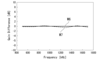
- FIG. 9 is a diagram showing an example of antenna characteristics when a conductive film 13 having a relatively high resistance is used in the vehicle antenna device 1 of this embodiment.
- the horizontal axis of the graph indicates reception frequency
- the vertical axis indicates reception voltage (dB).
- a solid line W6 indicates the antenna sensitivity when the conductive film 13 is a copper tape with a size of 50 mm ⁇ 500 mm
- a dashed line W7 indicates the conductive film 13 with a size of 50 mm ⁇ 500 mm and a sheet resistance of 150 ⁇ / ⁇ .
- Antenna sensitivity for film is shown.
- a solid line W6 and a dashed line W7 are measured values.
- solid line W6 with low resistance (for example, 0.1 ⁇ / ⁇ or less) and the conductive film with high resistance (broken line W7).
- 60 dB or more can be secured in the frequency band of broadcast waves. That is, a relatively high-resistance conductive film 13 having a sheet resistance of about 150 ⁇ / ⁇ , such as a Low-E coat (conductive film for low radiation), can be used as an AM antenna.
- the Low-E coating may be applied not only to vehicle window glass attached to the roof, but also to side glass and rear glass.
- the vehicle antenna device 1 of this embodiment includes the glass substrate 11 (dielectric substrate) and the conductive film 13 .
- the glass substrate 11 has a first main surface F1 and a second main surface F2.
- the conductive film 13 is provided on the second main surface F2 side, and has an area of 0.025 m 2 or more in plan view of the glass substrate 11 .
- the conductive film 13 has a sheet resistance value of 1.5 ⁇ 10 3 ⁇ / ⁇ or less.
- the sheet resistance value of the conductive film 13 is more preferably 1.0 ⁇ 10 3 ⁇ / ⁇ or less, further preferably 500 ⁇ / ⁇ or less, and particularly preferably 200 ⁇ / ⁇ or less.
- the vehicle antenna device 1 can receive AM broadcast waves from a feeding point 16 electrically connected to the conductive film 13 .
- the vehicle antenna device 1 of the present embodiment for example, a coating such as a conductive film for heat ray reflection (heat ray reflective film), a conductive film for low radiation (Low-E coat), etc., can be applied to AM broadcast waves.
- a coating such as a conductive film for heat ray reflection (heat ray reflective film), a conductive film for low radiation (Low-E coat), etc.
- the vehicle antenna device 1 of the present embodiment can easily receive AM broadcast waves using the conductive film 13 in the vehicle glass 10 (vehicle window glass) using the conductive film 13 .
- the vehicle antenna device 1 of this embodiment can obtain a sufficient antenna gain in the frequency band of AM broadcast waves.
- the feeding point 16 is arranged in the central portion of the conductive film 13 away from the edge of the glass substrate 11 by 150 mm or more in plan view of the glass substrate 11 . Further, the outer edge of the conductive film 13 is substantially quadrangular in plan view of the glass substrate 11 . As a result, the vehicle antenna device 1 of the present embodiment can easily receive AM broadcast waves using the conductive film 13 in, for example, a roof antenna.
- the feeding point 16 electrically connected to the conductive film 13 is the first feeding point.
- the vehicle antenna device 1 includes an antenna 21 , an antenna electrode 15 , an antenna conductor 12 and a high-pass filter 40 .
- the antenna 21 is provided on the first main surface F1 side, and receives radio waves of at least one of frequencies in the VHF band and the UHF band.
- the antenna electrode 15 is arranged inside the outer edge of the void area VA inside the conductive film 13 in plan view of the glass substrate 11 .
- the antenna conductor 12 is connected to the antenna 21 and arranged on the first main surface F1 side.
- the high-pass filter 40 passes signals in at least one of the VHF and UHF frequency bands, and cuts off signals in the AM broadcast frequency band.
- Antenna conductor 12 is electrically connected to antenna electrode 15 .
- the vehicle antenna device 1 can receive radio waves of at least one of frequencies in the VHF band and the UHF band by a signal received using the antenna electrode 15 as a second feeding point.
- the conductive film 13 can be used both as a receiving antenna (AM antenna) for the frequency band of AM broadcast waves and as an antenna ground for the antenna 21.
- AM antenna receiving antenna
- a large area can be secured. Therefore, the vehicle antenna device 1 of the present embodiment can easily receive AM broadcast waves by using the conductive film 13, and can obtain a sufficient antenna gain for at least one of the radio waves in the VHF band and the UHF band. be done. Moreover, sufficient antenna gain can be obtained without mechanical processing such as drilling of the glass substrate 11 for the antenna 21 .
- the antenna conductor 12 and the antenna electrode 15 are electrically connected by capacitive coupling.
- the reception signal of the antenna 21 can be extracted from the antenna electrode 15 without perforating the glass substrate 11, and the antenna 21 can be mounted on the vehicle glass. It can be installed in any of 10 locations.
- the antenna 21 can receive the frequency of FM broadcast waves.
- the vehicle antenna device 1 includes an AM amplifier 31 and an FM amplifier 32 .
- a signal in the frequency band of AM broadcast waves is input to the AM amplifier 31 from the feeding point 16 (first feeding point).
- a signal in the frequency band of FM broadcast waves is input to the FM amplifier 32 from the antenna electrode 15 (second feeding point).
- the vehicle antenna device 1 of the present embodiment can appropriately receive signals in both the AM broadcast wave frequency band and the FM broadcast wave frequency band.
- the high-pass filter 40 is the capacitor C1.
- Capacitor C1 has a capacitance of 5 pF to 150 pF. Further, the capacitance of the capacitor C1 is more preferably 5 pF to 100 pF. As a result, the vehicle antenna device 1 of the present embodiment can realize the high-pass filter 40 with a simple configuration of the capacitor C1.
- the antenna 21 is arranged to be surrounded by an antenna cover 22 (cover member) projecting outward from the first main surface F1 side of the glass substrate 11 .
- the dielectric substrate is the glass substrate 11 .
- the glass substrate 11 may be attached to the roof of the vehicle parallel to the horizontal plane of the vehicle, or may be applied as a side glass or a rear glass.
- FIG. 10 is a cross-sectional view showing an example of the vehicle antenna device 1a of the second embodiment. Note that the perspective view of the vehicle antenna device 1a of this embodiment is the same as that of the first embodiment shown in FIG. 10, since the configuration of the antenna cover 22 is the same as that of the first embodiment shown in FIG. 2, the illustration thereof is omitted here.
- the vehicle antenna device 1a includes a vehicle glass 10a, an amplifier section 30, and a high-pass filter 40.
- the vehicle glass 10a includes a glass substrate 11, an antenna conductor 12a, a conductive film 13, an antenna electrode 15a, a feeding point 16, a shield layer 17, and a connection conductor .
- the same reference numerals are given to the same configurations as those of the first embodiment shown in FIG. 2, and the description thereof will be omitted.
- connection conductor 18 is a conductor arranged in the through hole of the glass substrate 11 .
- the antenna conductor 12a and the antenna electrode 15a of this embodiment are directly connected by a connection conductor 18.
- FIG. Other configurations of this embodiment are the same as those of the above-described first embodiment shown in FIG. 2, so description thereof will be omitted here.
- a signal in the frequency band of AM broadcast waves is input from the feeding point 16 (first feeding point) to the AM amplifier 31 of the amplifier section 30 .
- a signal in the frequency band of FM broadcast waves is input to the FM amplifier 32 of the amplifier section 30 from the antenna electrode 15a (second feeding point).
- the antenna conductor 12a and the antenna electrode 15a are directly connected by the connection conductor 18 arranged in the through-hole of the glass substrate 11 .
- a sufficient antenna gain of the antenna 21 can be obtained with minimal mechanical processing of the glass substrate 11, as in the first embodiment.
- FIG. 11 is a cross-sectional view showing an example of the vehicle antenna device 1b of this embodiment. Note that the perspective view of the vehicle antenna device 1b of this embodiment is the same as that of the first embodiment shown in FIG. 11, since the configuration of the antenna cover 22 is the same as that of the first embodiment shown in FIG. 2, illustration thereof is omitted here.
- the vehicle antenna device 1b includes a vehicle glass 10b, an amplifier section 30, and a high-pass filter 40.
- the vehicle glass 10b is, for example, laminated glass.
- the vehicle glass 10b includes two glass substrates 11 (11-1, 11-2), an antenna conductor 12, a conductive film 13, an intermediate film 14, an antenna electrode 15, a signal electrode 16a, and a connection conductor 18a. and
- a glass substrate 11-1 (an example of a first dielectric substrate) and a glass substrate 11-2 (an example of a second dielectric substrate) are glass substrates for laminated glass that are bonded with an intermediate film 14.
- Each of the glass substrates 11-1 and 11-2 is an example of a dielectric substrate.
- the glass substrate 11-1 may be referred to as a first glass substrate.
- the glass substrate 11-2 may be called a second glass substrate.
- the main surface of the glass substrate 11-1 on the outside of the vehicle is the first main surface F1.
- the main surface opposite to the first main surface F1 side is the second main surface F2.
- the main surface of the glass substrate 11-2 on the side of the glass substrate 11-1 is the third main surface F3.
- the principal surface opposite to the third principal surface F3 is the fourth principal surface F4.
- the glass substrate 11-2 is arranged in parallel with the second main surface F2 so as to face the second main surface F2 side of the glass substrate 11-1.
- the conductive film 13 and the intermediate film 14 are sandwiched between the glass substrate 11-1 and the glass substrate 11-2.
- conductive film 13 is arranged so as to be in contact with second main surface F2, but may be arranged so as to be in contact with third main surface F3.
- the intermediate film 14 may have a structure in which a plurality of layers are laminated.
- the conductive film 13 may be arranged so as to be inserted between the interlayers of the multiple layers of the intermediate film 14 .
- the conductive film 13 may be a conductor contained in a light control film capable of controlling visible light transmittance by applying an AC voltage.
- the light control film consists of a pair of resin substrates, a pair of ITO (Indium Tin Oxide) films, a transparent conductive polymer, a laminated film of a metal layer and a dielectric layer, silver nanowires, silver or copper metal mesh, etc. and a light control layer sandwiched between the pair of conductive films 13 .
- the ITO film is provided on the main surface of the resin substrate. Since the main surfaces of the pair of resin substrates face each other, the pair of ITO films also face each other.
- the light control layer is a molecular layer such as liquid crystal having optical anisotropy.
- the conductive film 13 may be a conductive film included in a solar panel.
- the conductive film 13 is shown as a single layer for the sake of convenience, but when the conductive film 13 includes a light control film, the conductive film 13 is a pair of conductive films.
- the vehicle glass 10b may have the shielding layer 17 (not shown) that shields visible light, as described in the first embodiment.
- the shielding layer 17 can be arranged on at least one of the second main surface F2, the third main surface F3 and the fourth main surface F4.
- the shielding layer 17 may be arranged, for example, only on the fourth main surface F4.
- the intermediate film 14 is, for example, an adhesive layer such as a transparent polyvinyl butyral (PVB) film, ethylene-vinyl acetate copolymer (EVA) film, cycloolefin polymer (COP) film.
- the intermediate film 14 is arranged between the glass substrate 11-1 and the glass substrate 11-2.
- the intermediate film 14 adheres the glass substrate 11-1, the conductive film 13, and the glass substrate 11-2.
- the laminate structure bonded by the interlayer 14 forms a laminated glass.
- the antenna electrode 15 is arranged inside the outer edge of the hole area VA in plan view of the glass substrate 11-2 (11).
- the antenna electrode 15 is arranged on the second main surface F2 side and electrically connected to the antenna conductor 12 .
- the antenna electrode 15 is arranged, for example, in contact with the fourth main surface F4 of the glass substrate 11-2.
- Antenna electrode 15 is formed to face antenna conductor 12 .
- the glass substrate 11-1, the intermediate film 14, and the glass substrate 11-2 are sandwiched between the antenna electrode 15 and the antenna conductor 12.
- FIG. In this embodiment, the antenna conductor 12 and the antenna electrode 15 are arranged so as to be electrically connected by capacitive coupling.
- the antenna electrode 15 functions as a second feeding point.
- the thickness of the glass substrate 11-1, the intermediate film 14, and the glass substrate 11-2 is, for example, about 2 mm, about 1 mm, and about 2 mm, respectively.
- the distance between the antenna conductor 12 and the antenna electrode 15 is approximately 5 mm.
- the dielectric distance between conductors should be less than 30 mm, preferably 20 mm or less, more preferably 10 mm or less. Since the thickness of the vehicle glass 10b is typically about 5 mm as described above, the distance between the antenna conductor 12 and the antenna electrode 15 is sufficient for capacitive coupling.
- capacitive coupling between the antenna conductor 12 and the antenna electrode 15 is possible if the thickness of the vehicle glass 10b, which is laminated glass, is less than 30 mm. It can be configured as a circuit that amplifies the signal received by the antenna 21 with the amplifier section 30 .
- the signal electrode 16a is an electrode arranged on the fourth main surface F4 side of the glass substrate 11-2, and functions as a feeding point for the conductive film 13 functioning as an AM antenna for receiving AM broadcast waves.
- the signal electrode 16a is arranged so as to be electrically connected to the conductive film 13 and the connection conductor 18a. Thus, the signal electrode 16a is arranged at a position overlapping the conductive film 13 in plan view of the glass substrate 11-2 (11).
- connection conductor 18a is a conductor penetrating through the glass substrate 11-2.
- the connection conductor 18a electrically and directly connects the conductive film 13 and the signal electrode 16a.
- Other configurations of this embodiment are the same as those of the above-described first embodiment shown in FIG. 2, so description thereof will be omitted here.
- a signal in the frequency band of AM broadcast waves is input to the AM amplifier 31 of the amplifier section 30 from the signal electrode 16a (first feeding point).
- a signal in the frequency band of FM broadcast waves is input from the antenna electrode 15 (second feeding point) to the FM amplifier 32 of the amplifier section 30 .
- the glass substrate 11 is the glass substrate 11-1 (first dielectric substrate).
- the vehicle antenna device 1b includes a glass substrate 11-2 arranged parallel to the second main surface F2 on the side of the second main surface F2 of the glass substrate 11-1, and a glass substrate 11-1 and a glass substrate 11-. 2, and an intermediate film 14 disposed between.
- the glass substrate 11-2 has a third principal surface F3 on the side of the glass substrate 11-1 and a fourth principal surface F4 on the side opposite to the third principal surface F3.
- the conductive film 13 is arranged between the glass substrates 11-1 and 11-2, and the antenna electrode 15 is arranged on the fourth main surface F4 side.
- the conductive film 13 is arranged, for example, in contact with the second main surface F2.
- the vehicle antenna device 1b of the present embodiment even when the laminated glass including the glass substrate 11-1 (first dielectric substrate) and the glass substrate 11-2 is used, The same effects as in the first embodiment described above can be obtained, and AM broadcast waves can be easily received using the conductive film 13 in the vehicle glass 10b using the conductive film 13 . Further, in the vehicle antenna device 1b of the present embodiment, a sufficient antenna gain can be obtained with respect to the antenna 21 with minimal mechanical processing of the glass substrate 11. FIG.
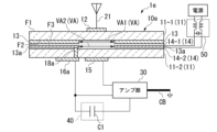
- FIG. 12 is a cross-sectional view showing an example of the vehicle antenna device 1c of this embodiment. Note that the perspective view of the vehicle antenna device 1c of this embodiment is the same as that of the first embodiment shown in FIG. 12, since the configuration of the antenna cover 22 is the same as that of the first embodiment shown in FIG. 2, illustration thereof is omitted here.
- the vehicle antenna device 1c includes a vehicle glass 10c, an amplifier section 30, and a high-pass filter 40.
- the vehicle glass 10c is, for example, laminated glass.
- the vehicle glass 10c includes two glass substrates 11 (11-1, 11-2), an antenna conductor 12, a conductive film 13a, an intermediate film 14 (14-1, 14-2), and an antenna electrode 15. , a signal electrode 16a and a connection conductor 18a.
- the same reference numerals are given to the same configurations as those of the third embodiment shown in FIG. 11, and the description thereof will be omitted.
- the intermediate film 14 includes an intermediate film 14-1 (first intermediate film) and an intermediate film 14-2 (second intermediate film).
- the intermediate film 14-1 and the intermediate film 14-2 are, for example, a PVB film, an EVA film, a COP film, or the like, and it is preferable to use the same material for the intermediate film 14-1 and the intermediate film 14-2.
- the conductive film 13a is a light control film containing a conductor.
- the conductive film 13a is sandwiched between the intermediate films 14-1 and 14-2.
- the conductive film 13a is shown as a single layer for the sake of convenience, but when the conductive film 13a includes a light control film, the conductive film 13a is a pair of conductive films.
- the conductive film 13a is sandwiched between the intermediate films 14-1 and 14-2.
- the connection conductor 18a of this embodiment is a conductor penetrating through the glass substrate 11-2. The connection conductor 18a electrically and directly connects the conductive film 13a and the signal electrode 16a.
- the conductive film 13a which is a light control film, functions as an AM antenna and as an antenna ground for the antenna 21.
- a signal in the frequency band of FM broadcast waves is input from the antenna electrode 15 (second feeding point) to the FM amplifier 32 of the amplifier section 30 .
- a choke coil 50 is connected to the conductive film 13a, which is a dimming film, in order to prevent leakage of received signals of AM broadcast waves.
- the intermediate film 14 includes the intermediate film 14-1 (first intermediate film) and the intermediate film 14-2 (second intermediate film).
- the conductive film 13a is sandwiched between the intermediate films 14-1 and 14-2.
- the conductive film 13a is a light control film containing a conductor.
- the conductive film 13a is arranged between the glass substrate 11-1 (first dielectric substrate) and the glass substrate 11-2 (second dielectric substrate). It is Therefore, for example, even if the conductive film 13a is a light control film, the same effects as in the above-described third embodiment can be obtained. 13a can be used to easily receive AM broadcast waves. Further, according to the vehicle antenna device 1c of the present embodiment, the conductive film 13a, which is a light control film, functions as an antenna ground for the antenna 21. Sufficient antenna gain can be obtained by processing.
- a vehicle antenna device 1d according to a fifth embodiment will be described with reference to the drawings.
- FIG. 13 is a sectional view showing an example of the vehicle antenna device 1d of this embodiment. Note that the perspective view of the vehicle antenna device 1d of this embodiment is the same as that of the first embodiment shown in FIG. 13, since the configuration of the antenna cover 22 is the same as that of the first embodiment shown in FIG. 2, the illustration is omitted here.
- the vehicle antenna device 1d includes a vehicle glass 10d, an amplifier section 30, and a high-pass filter 40.
- the vehicle glass 10d is, for example, laminated glass.
- the vehicle glass 10d includes two glass substrates 11 (11-1, 11-2), an antenna conductor 12, a conductive film 13b, an intermediate film 14, an antenna electrode 15, a signal electrode 16a, and a connection conductor 18a. and
- the same components as those of the third embodiment shown in FIG. 11 are denoted by the same reference numerals, and description thereof will be omitted.
- the conductive film 13b is, for example, a heat ray reflective conductive film (heat ray reflective film) or a low radiation conductive film (Low-E coat).
- the conductive film 13b is arranged between the intermediate film 14 and the glass substrate 11-2 in contact with the third main surface F3 of the glass substrate 11-2.
- the conductive film 13b may be arranged in contact with the fourth main surface F4 of the glass substrate 11-2.
- connection conductor 18a of this embodiment is a conductor penetrating through the glass substrate 11-2.
- the connection conductor 18a electrically and directly connects the conductive film 13b and the signal electrode 16a.
- the conductive film 13b functions as an AM antenna and as an antenna ground for the antenna 21.
- a signal in the AM broadcast wave frequency band received by the conductive film 13b is input to the AM amplifier 31 of the amplifier unit 30 from the signal electrode 16a (first feeding point).
- a signal in the frequency band of FM broadcast waves is input from the antenna electrode 15 (second feeding point) to the FM amplifier 32 of the amplifier section 30 .
- the conductive film 13b is arranged in contact with the third main surface F3 or the fourth main surface F4.
- the conductive film 13b is, for example, a heat ray reflective conductive film (heat ray reflective film) or a low radiation conductive film (Low-E coat).
- the vehicle antenna device 1d of the present embodiment even when the conductive film 13b is arranged in contact with the third main surface F3 or the fourth main surface F4, the third embodiment described above can be used. An effect similar to that of the embodiment can be obtained, and AM broadcast waves can be easily received using the conductive film 13b.
- the conductive film 13b functions as an antenna ground for the antenna 21. Therefore, a sufficient antenna gain can be obtained with respect to the antenna 21 with minimal mechanical processing of the glass substrate 11. can get.
- FIG. 14 is a cross-sectional view showing an example of the vehicle antenna device 1e of this embodiment.
- the perspective view of the vehicle antenna device 1e of this embodiment is the same as that of the first embodiment shown in FIG. 14, the configuration of the antenna cover 22 is the same as that of the first embodiment shown in FIG. 2, so illustration is omitted here.
- a choke coil 50 is connected to the conductive film 13a, which is a dimming film, in order to prevent leakage of received signals of AM broadcast waves, as in the fourth embodiment shown in FIG.
- the vehicle antenna device 1e includes a vehicle glass 10e, an amplifier section 30, and a high-pass filter 40.
- the vehicle glass 10e is, for example, laminated glass.
- the vehicle glass 10e includes two glass substrates 11 (11-1, 11-2), an antenna conductor 12, a conductive film 13 and a conductive film 13a, an intermediate film 14 (14-1, 14-2), It has an antenna electrode 15, a signal electrode 16a, and a connection conductor 18a.
- the same reference numerals are assigned to the same configurations as those of the third and fourth embodiments shown in FIGS. 11 and 12, and the description thereof will be omitted.
- the conductive film 13 is, for example, a conductive film for heat ray reflection (heat ray reflective film).
- the conductive film 13 is arranged in contact with the second main surface F2 of the glass substrate 11-1.
- the sheet resistance value of the conductive film 13 is, for example, lower than the sheet resistance value of the conductive film 13a.
- the conductive film 13a is, for example, a light control film containing a conductor.
- the light control film is a light control film that can electrically change the transmittance of light, and includes, for example, a transparent conductive film such as ITO.
- the conductive film 13a is shown as a single layer for the sake of convenience.
- the conductive film 13a is sandwiched between the intermediate films 14-1 and 14-2.
- the conductive film 13a has second vacant regions VA2 arranged so as to overlap the first vacant regions VA1, which are the vacant regions VA of the conductive film 13, in plan view of the glass substrate 11-1.
- the intermediate film 14 of this embodiment includes an intermediate film 14-1 (first intermediate film) and an intermediate film 14-2 (second intermediate film).
- the intermediate film 14-1 and the intermediate film 14-2 are, for example, a PVB film, an EVA film, a COP film, or the like.
- the connection conductor 18a of this embodiment is a conductor penetrating through the glass substrate 11-2.
- the connection conductor 18a electrically and directly connects the conductive film 13a and the signal electrode 16a.
- the connection conductor 18a may electrically connect the conductive film 13 and the signal electrode 16a directly.
- the conductive film 13 a that is the light control film or the conductive film 13 for heat ray reflection functions as an AM antenna and as an antenna ground for the antenna 21 .
- a signal in the frequency band of the AM broadcast wave received by the conductive film 13a which is a light control film or the conductive film 13 for heat ray reflection is input to the AM amplifier 31 of the amplifier unit 30 from the signal electrode 16a (first feeding point).
- a signal in the frequency band of FM broadcast waves is input from the antenna electrode 15 (second feeding point) to the FM amplifier 32 of the amplifier section 30 .
- the intermediate film 14 includes the intermediate film 14-1 and the intermediate film 14-2, and the conductive films include the conductive film 13 (first conductive film) and the conductive film 13a (second conductive film).
- the conductive film 13 and the conductive film 13a are located on the second main surface F2, between the intermediate films 14-1 and 14-2, on the third main surface F3, and on the fourth main surface F4. They are arranged at two of the upper positions, and arranged in order from the one closest to the glass substrate 11-1.
- the conductive film 13a has a second hole area VA2 arranged so as to overlap the first hole area VA1, which is the hole area VA of the conductive film 13, in plan view of the glass substrate 11-1.
- the vehicle antenna device 1e of the present embodiment even when both the conductive film 13 and the conductive film 13a are provided, the same effects as in the above-described third embodiment can be obtained.
- the conductive film 13 can be used to easily receive AM broadcast waves.
- the conductive film 13a or the conductive film 13 functions as an antenna ground for the antenna 21. Therefore, the minimum mechanical processing of the glass substrate 11 for the antenna 21 is sufficient. antenna gain is obtained.
- the conductive film 13 is arranged in contact with the second main surface F2, and the conductive film 13a is sandwiched between the intermediate films 14-1 and 14-2.
- the conductive film 13 is, for example, a conductor for heat ray reflection (heat ray reflective film), and the conductive film 13a is, for example, a light control film containing a conductor.
- the vehicle antenna device 1e of the present embodiment can easily receive AM broadcast waves even when it includes both a conductor for heat ray reflection (heat ray reflective film) and a light control film, for example. .
- a vehicle antenna device 1f of a seventh embodiment will be described with reference to the drawings.
- a modified example in which laminated glass is used and both a conductive film 13a as a light control film and a conductive film 13c as a conductor for a low-emissivity film (Low-E coat) are provided will be described.
- FIG. 15 is a cross-sectional view showing an example of the vehicle antenna device 1f of this embodiment. Note that the perspective view of the vehicle antenna device 1f of this embodiment is the same as that of the first embodiment shown in FIG. 15, the configuration of the antenna cover 22 is the same as that of the first and fourth embodiments shown in FIGS. 2 and 12, so illustration is omitted here.
- the vehicle antenna device 1f includes a vehicle glass 10f, an amplifier section 30, and a high-pass filter 40.
- the vehicle glass 10f is, for example, laminated glass.
- the vehicle glass 10f includes two glass substrates 11 (11-1, 11-2), an antenna conductor 12, conductive films 13a and 13c, an intermediate film 14, an antenna electrode 15, and a feeding point 16.
- a choke coil 50 is connected to the conductive film 13a, which is a dimming film, in order to prevent leakage of received signals of AM broadcast waves, as in the fourth embodiment shown in FIG.
- the same reference numerals are given to the same configurations as those of the first and fourth embodiments shown in FIGS. 2 and 12, and the description thereof will be omitted.
- the conductive film 13c is, for example, a conductive film for low radiation (Low-E coat).
- the conductive film 13c is arranged in contact with the fourth main surface F4 of the glass substrate 11-2.
- the Low-E coat is provided on the fourth main surface F4
- the conductive film 13c has third hole regions VA3 arranged so as to overlap with the first hole regions VA1 in plan view of the glass substrate 11-1.
- it is preferable that the outer edge of the first hole area VA1 and the outer edge of the third hole area VA3 are aligned with each other, although some misalignment is permissible.
- the feeding point 16 of this embodiment is a part of the conductive film 13c and is electrically connected to the conductive film 13c.
- the vehicle antenna device 1f can receive AM broadcast waves from the feeding point 16 .
- the feeding point 16 is arranged at the center of the conductive film 13, which is 150 mm or more away from the edge of the glass substrate 11-2 in plan view of the glass substrate 11-2.
- the conductive film 13c which is a conductive film for low radiation (Low-E coat) functions as an AM antenna and as an antenna ground for the antenna 21.
- a signal in the frequency band of FM broadcast waves is input from the antenna electrode 15 (second feeding point) to the FM amplifier 32 of the amplifier section 30 .
- the conductive film 13a (first conductive film) is sandwiched between the intermediate films 14-1 and 14-2.
- Conductive film 13c (second conductive film) is arranged in contact with fourth main surface F4.
- the conductive film 13a is, for example, a light control film containing a conductor.
- the conductive film 13c is a conductor for a low emissivity film (Low-E coat).
- FIG. 16 is a cross-sectional view showing an example of the vehicle antenna device 1g of this embodiment. Note that the perspective view of the vehicle antenna device 1g of this embodiment is the same as that of the first embodiment shown in FIG. Also, in FIG. 16, the configuration of the antenna cover 22 is the same as that of the first embodiment shown in FIG. 2, and therefore illustration thereof is omitted here.
- a vehicle antenna device 1g includes a vehicle glass 10g, an amplifier section 30, and a high-pass filter 40.
- the vehicle glass 10g is, for example, laminated glass.
- a vehicle glass 10g includes two glass substrates 11 (11-1, 11-2), an antenna conductor 12, a conductive film 13, an intermediate film 14, an antenna electrode 15, and a signal electrode 16b.
- This embodiment differs from the above-described third embodiment in that the connection conductor 18a is not provided.
- the same reference numerals are given to the same configurations as those of the third embodiment shown in FIG. 11, and the description thereof will be omitted.
- the signal electrode 16b is arranged so as to be electrically connected to the conductive film 13 by capacitive coupling. That is, the signal electrode 16b is arranged at a position overlapping the conductive film 13 in plan view of the glass substrate 11-2 (11). Further, the signal electrode 16b is formed in a square loop shape in plan view of the glass substrate 11-2 (11). That is, the signal electrode 16b has square outer and inner edges.
- the conductive film 13 functions as an AM antenna and as an antenna ground for the antenna 21 .
- a signal in the frequency band of the AM broadcast wave received by the conductive film 13 is electrically connected to the signal electrode 16b (first feeding point) by capacitive coupling, and is transmitted from the feeding point 16 (first feeding point) to the AM of the amplifier section 30. Input to the amplifier 31 .
- a signal in the frequency band of FM broadcast waves is input from the antenna electrode 15 (second feeding point) to the FM amplifier 32 of the amplifier section 30 .
- the conductive film 13 and the signal electrode 16b are electrically connected by capacitive coupling.
- the vehicle antenna device 1g of the present embodiment extracts the received signal of the AM broadcast wave from the signal electrode 16b (first feeding point) without perforating the glass substrate 11-2 (11).
- the conductive film 13 can be used to receive AM broadcast waves more simply.
- the present invention is not limited to the above embodiments, and can be modified without departing from the gist of the present invention.
- the antenna section 20 is a shark fin antenna
- the antenna section 20 is a shark fin antenna
- the dielectric substrate is the glass substrate 11
- the present invention is not limited to this. It's okay.
- the vehicle glasses 10b to 10g do not include the shielding layer 17, but in the third to eighth embodiments, the shielding layer 17 is provided.
- the shielding layer 17 is not provided. You may do so.
- the capacitor C1 of the high-pass filter 40 is configured by a capacitor element.
- the glass substrate 11 or the like may be used for capacitive coupling to constitute the capacitor C1.
- the capacitor C1 may be configured by utilizing the overlapping of the conductive films 13 (13a, 13b) and the vehicle body BD.
- Filter 40 may also be configured as a bandstop filter.
- a third conductive film (not shown) in contact with the fourth main surface F4 of the glass substrate 11-2 may be provided.
- the third conductive film in contact with the fourth main surface F4 is preferably arranged so as not to contact with the antenna electrode 15 .
- the conductive film 13 which is the first conductive film, is the heat ray reflecting film and the second conductive film.
- a combination in which the conductive film 13a is (a conductor contained in) a light control film and the third conductive film is a Low-E coat can be mentioned.
- the fourth main surface F4 has a Low-E coat, it is preferable to overcoat with an insulating layer so that the Low-E coat is not exposed on the surface.
- the connection conductor 18a may be omitted in FIG.
- the feed point 16 may be provided as part of the Low-E coat, which is the third conductive film (as shown in FIG. 15).
- the vehicle antenna device 1b of the third embodiment shown in FIG. 11 to the vehicle antenna device 1e of the sixth embodiment shown in FIG. may be directly connected by a connecting conductor 18 (connecting conductor as shown in the second embodiment) arranged in the hole.
- a connecting conductor 18 connecting conductor as shown in the second embodiment
Abstract
A vehicle antenna device of the present invention comprises a dielectric substrate having a first main surface and a second main surface, and an electrically conductive film provided on the second main surface side and having an area of more than or equal to 0.025 m2 in a plan view of the dielectric substrate. The electrically conductive film has a sheet resistance value of less than or equal to 1.5×10³Ω/sq. AM broadcast waves can be received from a feed point electrically connected to the electrically conductive film.
Description
本発明は、車両用アンテナ装置に関する。
本願は、2021年11月12日に日本に出願された特願2021-184698号に基づき優先権を主張し、その内容をここに援用する。 The present invention relates to a vehicle antenna device.
This application claims priority based on Japanese Patent Application No. 2021-184698 filed in Japan on November 12, 2021, the content of which is incorporated herein.
本願は、2021年11月12日に日本に出願された特願2021-184698号に基づき優先権を主張し、その内容をここに援用する。 The present invention relates to a vehicle antenna device.
This application claims priority based on Japanese Patent Application No. 2021-184698 filed in Japan on November 12, 2021, the content of which is incorporated herein.
近年、車両の開口部、とくに車両用窓ガラスには、Low-E、熱線反射膜等の(透明)導電膜がコーティングされたり、電気的(アクティブ)に可視光線透過率を変化できる調光フィルムを備えたり、熱的/光学的な付加価値が提供されている。
一方で、ガラス等の誘電体に導電膜をコーティングすると、従来の車両用窓ガラスのように、車両用窓ガラスに線条の導体パターンを配置して所定の放送波を受信する、ガラスアンテナとしての所望のアンテナ利得が得られない。導電膜コーティングをアンテナとして利用するものとしては、例えば、特許文献1が知られている。 In recent years, vehicle openings, especially vehicle window glass, are coated with (transparent) conductive films such as Low-E and heat ray reflective films, and light control films that can electrically (actively) change the visible light transmittance. or provide thermal/optical added value.
On the other hand, when a conductive film is coated on a dielectric such as glass, it can be used as a glass antenna that receives a predetermined broadcast wave by arranging a wire conductor pattern on the vehicle window glass like a conventional vehicle window glass. desired antenna gain is not obtained. For example, Japanese Patent Laid-Open No. 2002-200003 is known as a technique that uses a conductive film coating as an antenna.
特許文献1では、一対のバスバー間に電圧を印加することで加熱する導電膜を備え、導電膜を含むアンテナ素子が、地上デジタルテレビ放送波、DAB(Digital Audio Broadcast)の放送波、FM放送波を受信できるアンテナとして機能することが記載されている。また、特許文献1では、導電膜の導体部分の周りが除去され高抵抗化された領域の格子部を設けることで、AM放送波を受信できるアンテナとしても機能できる。
In Patent Document 1, an antenna element including a conductive film that is heated by applying a voltage between a pair of bus bars is used for terrestrial digital television broadcast waves, DAB (Digital Audio Broadcast) broadcast waves, and FM broadcast waves. It is described that it functions as an antenna that can receive Further, in Patent Document 1, by providing a grid portion of a region in which the conductor portion of the conductive film is removed and the resistance thereof is increased, the antenna can function as an antenna capable of receiving AM broadcast waves.
しかしながら、このような導電膜を用いたアンテナとして、AM放送波を受信させるアンテナを実現する場合、例えば、格子部を設けるなど導電膜を加工する工数が増え、工程が複雑化する問題があった。
However, when realizing an antenna that receives AM broadcast waves as an antenna using such a conductive film, there is a problem that the number of man-hours for processing the conductive film, such as providing a grid portion, increases, and the process becomes complicated. .
本発明は、導電膜を用いた車両用窓ガラスにおいて、導電膜を利用して簡易的にAM放送波を受信できる車両用アンテナ装置を提供する。
The present invention provides a vehicle antenna device that can easily receive AM broadcast waves using a conductive film in a vehicle window glass using a conductive film.
本発明の一態様に係る車両用アンテナ装置は、第1主面と第2主面とを有する誘電体基板と、前記第2主面側に備えられ、前記誘電体基板の平面視における面積が0.025m2以上である導電膜とを備える。前記導電膜は、1.5×10³Ω/□以下のシート抵抗値を有し、前記導電膜に電気的に接続される給電点より、AM放送波を受信可能である。
A vehicle antenna device according to an aspect of the present invention includes a dielectric substrate having a first main surface and a second main surface, and a dielectric substrate provided on the second main surface side, the area of the dielectric substrate in plan view being a conductive film that is 0.025 m 2 or more. The conductive film has a sheet resistance value of 1.5×10 3 Ω/□ or less, and can receive AM broadcast waves from a feeding point electrically connected to the conductive film.
本発明の一態様に係る車両用アンテナ装置においては、前記給電点は、前記誘電体基板の平面視において、前記誘電体基板の端辺から150mm以上離れる、前記導電膜の中央部に配置されてもよい。
In the vehicle antenna device according to one aspect of the present invention, the feeding point is arranged in a central portion of the conductive film, which is separated from an edge of the dielectric substrate by 150 mm or more in plan view of the dielectric substrate. good too.
本発明の一態様に係る車両用アンテナ装置においては、前記導電膜の外縁は、前記誘電体基板の平面視において、略四角形であってもよい。
In the vehicle antenna device according to one aspect of the present invention, the outer edge of the conductive film may be substantially quadrangular in plan view of the dielectric substrate.
本発明の一態様に係る車両用アンテナ装置においては、前記導電膜に電気的に接続される給電点は、第1給電点であり、前記第1主面側に備えられ、VHF帯及びUHF帯の周波数の少なくとも一方の電波を受信するアンテナと、前記誘電体基板の平面視において、前記導電膜の内部に有する空孔領域の外縁よりも内側に配置されるアンテナ電極と、前記アンテナと接続され、前記第1主面側に配置されるアンテナ導体と、前記導電膜と接地導体との間で、VHF帯及びUHF帯の周波数の少なくとも一方の電波の周波数帯の信号を通過させ、AM放送波の周波数帯の信号を遮断するフィルタとを備える。前記アンテナ導体は、前記アンテナ電極と電気的に接続し、前記アンテナ電極を第2給電点として受信した信号により、VHF帯及びUHF帯の周波数の少なくとも一方の電波を受信可能であってもよい。
In the vehicle antenna device according to one aspect of the present invention, the feeding point electrically connected to the conductive film is a first feeding point, provided on the first main surface side, and having VHF band and UHF band an antenna for receiving radio waves of at least one of the frequencies of; an antenna electrode arranged inside an outer edge of a pore region inside the conductive film in a plan view of the dielectric substrate; and connected to the antenna. , between the antenna conductor arranged on the first main surface side and the conductive film and the ground conductor, passing a signal in at least one of the radio wave frequency band of VHF band and UHF band, and AM broadcast wave and a filter that cuts off signals in the frequency band of The antenna conductor may be electrically connected to the antenna electrode, and may be capable of receiving radio waves of at least one of VHF band and UHF band frequencies by a signal received using the antenna electrode as a second feeding point.
本発明の一態様に係る車両用アンテナ装置においては、前記アンテナ導体と、前記アンテナ電極とは、容量結合によって電気的に接続されてもよい。
In the vehicle antenna device according to one aspect of the present invention, the antenna conductor and the antenna electrode may be electrically connected by capacitive coupling.
本発明の一態様に係る車両用アンテナ装置においては、前記アンテナ導体と、前記アンテナ電極とは、前記誘電体基板の貫通孔内に配置される接続導体によって直接接続されてもよい。
In the vehicle antenna device according to one aspect of the present invention, the antenna conductor and the antenna electrode may be directly connected by a connection conductor arranged in a through hole of the dielectric substrate.
本発明の一態様に係る車両用アンテナ装置においては、前記誘電体基板は、第1誘電体基板であり、前記第1誘電体基板の前記第2主面側に、前記第2主面と平行して配置される第2誘電体基板と、前記第1誘電体基板と前記第2誘電体基板との間に配置される中間膜とを備える。前記第2誘電体基板は、前記第1誘電体基板側の第3主面と、前記第3主面側とは反対側の第4主面と、を有し、前記導電膜は、前記第1誘電体基板と前記第2誘電体基板との間に配置され、前記アンテナ電極は、前記第4主面側に配置されてもよい。
In the vehicle antenna device according to one aspect of the present invention, the dielectric substrate is a first dielectric substrate, and the second main surface side of the first dielectric substrate has a dielectric parallel to the second main surface. and an intermediate film disposed between the first dielectric substrate and the second dielectric substrate. The second dielectric substrate has a third main surface on the side of the first dielectric substrate and a fourth main surface on the side opposite to the third main surface, and the conductive film has the third main surface. The antenna electrode may be arranged between the first dielectric substrate and the second dielectric substrate, and the antenna electrode may be arranged on the fourth main surface side.
本発明の一態様に係る車両用アンテナ装置においては、前記導電膜は、前記第2主面に接して配置されてもよい。
In the vehicle antenna device according to one aspect of the present invention, the conductive film may be arranged in contact with the second main surface.
本発明の一態様に係る車両用アンテナ装置においては、前記中間膜には、第1中間膜と第2中間膜とが含まれ、前記導電膜は、前記第1中間膜と前記第2中間膜との間に挟持されてもよい。
In the vehicle antenna device according to one aspect of the present invention, the intermediate film includes a first intermediate film and a second intermediate film, and the conductive film includes the first intermediate film and the second intermediate film. may be sandwiched between
本発明の一態様に係る車両用アンテナ装置においては、前記導電膜は、導体を含む調光フィルムであってもよい。
In the vehicle antenna device according to one aspect of the present invention, the conductive film may be a light control film containing a conductor.
本発明の一態様に係る車両用アンテナ装置においては、前記導電膜は、前記第3主面、又は前記第4主面に接して配置されてもよい。
In the vehicle antenna device according to one aspect of the present invention, the conductive film may be arranged in contact with the third main surface or the fourth main surface.
本発明の一態様に係る車両用アンテナ装置においては、前記中間膜には、第1中間膜と第2中間膜とが含まれ、前記導電膜には、第1導電膜と第2導電膜とが含まれ、前記第1導電膜及び前記第2導電膜は、前記第2主面上の位置、前記第1中間膜と前記第2中間膜との間の位置、前記第3主面上の位置、及び前記第4主面上の位置のうちの2つの位置に配置され、前記第1誘電体基板に近い方から順に配置され、前記第2導電膜は、前記第1誘電体基板の平面視において、前記第1導電膜の前記空孔領域である第1空孔領域と重なるように配置される第2空孔領域を有してもよい。
In the vehicle antenna device according to one aspect of the present invention, the intermediate film includes a first intermediate film and a second intermediate film, and the conductive film includes a first conductive film and a second conductive film. wherein the first conductive film and the second conductive film are located on the second main surface, between the first intermediate film and the second intermediate film, and on the third main surface and a position on the fourth main surface, and are arranged in order from the one closest to the first dielectric substrate, and the second conductive film is located on the plane of the first dielectric substrate. In view, it may have a second pore region arranged so as to overlap with the first pore region which is the pore region of the first conductive film.
本発明の一態様に係る車両用アンテナ装置においては、前記第1導電膜は、前記第2主面に接して配置され、前記第2導電膜は、前記第1中間膜と前記第2中間膜との間に挟持されてもよい。
In the vehicle antenna device according to one aspect of the present invention, the first conductive film is arranged in contact with the second main surface, and the second conductive film is formed of the first intermediate film and the second intermediate film. may be sandwiched between
本発明の一態様に係る車両用アンテナ装置においては、前記第1導電膜は、熱線反射用の導体であり、前記第2導電膜は、導体を含む調光フィルムであってもよい。
In the vehicle antenna device according to one aspect of the present invention, the first conductive film may be a conductor for reflecting heat rays, and the second conductive film may be a light control film including a conductor.
本発明の一態様に係る車両用アンテナ装置においては、前記導電膜には、前記第4主面に接して配置される第3導電膜が含まれ、前記第3導電膜は、低放射膜用の導体であってもよい。
In the vehicle antenna device according to one aspect of the present invention, the conductive film includes a third conductive film disposed in contact with the fourth main surface, and the third conductive film is for a low emissivity film. conductor.
本発明の一態様に係る車両用アンテナ装置においては、前記第1導電膜は、前記第1中間膜と前記第2中間膜との間に挟持され、前記第2導電膜は、前記第4主面に接して配置されてもよい。
In the vehicle antenna device according to one aspect of the present invention, the first conductive film is sandwiched between the first intermediate film and the second intermediate film, and the second conductive film It may be placed in contact with the surface.
本発明の一態様に係る車両用アンテナ装置においては、前記第1導電膜は、導体を含む調光フィルムであり、前記第2導電膜は、低放射膜用の導体であってもよい。
In the vehicle antenna device according to one aspect of the present invention, the first conductive film may be a light control film containing a conductor, and the second conductive film may be a conductor for a low emissivity film.
本発明の一態様に係る車両用アンテナ装置においては、前記アンテナは、FM放送波の周波数を受信可能であり、AMアンプ及びFMアンプを含み、AM放送波の周波数帯の信号が、前記第1給電点から前記AMアンプに入力され、FM放送波の周波数帯の信号が、前記第2給電点から前記FMアンプに入力されてもよい。
In the vehicle antenna device according to one aspect of the present invention, the antenna is capable of receiving the frequency of FM broadcast waves, includes an AM amplifier and an FM amplifier, and the signal in the frequency band of AM broadcast waves is the first A signal in a frequency band of an FM broadcast wave may be input from a feeding point to the AM amplifier and input to the FM amplifier from the second feeding point.
本発明の一態様に係る車両用アンテナ装置においては、前記フィルタは、コンデンサであり、前記コンデンサの容量は、5pF~150pFであってもよい。
In the vehicle antenna device according to one aspect of the present invention, the filter may be a capacitor, and the capacitor may have a capacity of 5 pF to 150 pF.
本発明の一態様に係る車両用アンテナ装置においては、前記アンテナは、前記誘電体基板の第1主面側から外側に突起するカバー部材によって囲まれて配置されてもよい。
In the vehicle antenna device according to one aspect of the present invention, the antenna may be surrounded by a cover member projecting outward from the first main surface side of the dielectric substrate.
本発明の一態様に係る車両用アンテナ装置においては、前記誘電体基板は、ガラス基板であってもよい。
In the vehicle antenna device according to one aspect of the present invention, the dielectric substrate may be a glass substrate.
本発明の一態様に係る車両用アンテナ装置においては、前記誘電体基板は、車両のルーフに、車両の水平面に平行に取付けられてもよい。
In the vehicle antenna device according to one aspect of the present invention, the dielectric substrate may be attached to the roof of the vehicle in parallel with the horizontal plane of the vehicle.
本発明の態様によれば、車両用アンテナ装置は、導電膜を用いた車両用窓ガラスにおいて、導電膜を利用して簡易的にAM放送波を受信できる。
According to the aspect of the present invention, the vehicle antenna device can easily receive AM broadcast waves using the conductive film in the vehicle window glass using the conductive film.
以下、本発明の実施形態の車両用アンテナ装置について、図面を参照して説明する。
実施形態の説明においては、文言「第1主面側」、文言「第2主面側」、文言「第3主面側」、及び文言「第4主面側」が用いられている。これら文言の各々の意味は、主面の表面上の位置、又は、主面に面する空間において主面から離れた位置を含む意味を有する。例えば、任意に選択される部材Aと主面との相対的な位置関係において、「部材Aが主面側に配置されている」とは、部材Aと主面とが直接的に接触している場合を意味するだけでなく、主面から部材Aが離間するように部材Aが配置されている場合も意味する。また、主面と部材Aとが離間している場合、主面と部材Aとの間に介在物があってもよいし、無くてもよい。 BEST MODE FOR CARRYING OUT THE INVENTION Hereinafter, vehicle antenna devices according to embodiments of the present invention will be described with reference to the drawings.
In the description of the embodiments, the words "first main surface side", "second main surface side", "third main surface side", and "fourth main surface side" are used. The meaning of each of these terms includes a location on the surface of the major surface or a location remote from the major surface in space facing the major surface. For example, in the relative positional relationship between the arbitrarily selected member A and the main surface, "the member A is arranged on the main surface side" means that the member A and the main surface are in direct contact with each other. It means not only the case where the member A is present, but also the case where the member A is arranged so as to be separated from the main surface. Moreover, when the main surface and the member A are spaced apart, there may or may not be an intervening material between the main surface and the member A.
[第1の実施形態]
図1は、第1の実施形態の車両用アンテナ装置1の一例を模式的に示す斜視図である。また、図2は、本実施形態の車両用アンテナ装置1の一例を示す断面図である。なお、図2に示す断面図は、図1のエリアAR1のAB線での断面図である。 [First Embodiment]
FIG. 1 is a perspective view schematically showing an example of the vehicle antenna device 1 of the first embodiment. FIG. 2 is a cross-sectional view showing an example of the vehicle antenna device 1 of this embodiment. The cross-sectional view shown in FIG. 2 is a cross-sectional view taken along line AB of area AR1 in FIG.
図1及び図2に示すように、車両用アンテナ装置1は、車両用ガラス10を用いている。車両用アンテナ装置1は、車両用ガラス10と、アンテナ部20と、アンプ部30と、フィルタ40とを備える。フィルタ40は、ハイパスフィルタでもよく、バンドストップフィルタでもよい。以下、とくにことわりがない限り、ハイパスフィルタ40として説明する。
As shown in FIGS. 1 and 2 , the vehicle antenna device 1 uses vehicle glass 10 . A vehicle antenna device 1 includes a vehicle glass 10 , an antenna section 20 , an amplifier section 30 and a filter 40 . Filter 40 may be a high-pass filter or a band-stop filter. Hereinafter, unless otherwise specified, the high-pass filter 40 will be described.
車両用ガラス10は、例えば、車両のルーフに装着されるルーフガラスである。車両用ガラス10は、車両のルーフに、車両の水平面に平行(略平行を含む)に取付けられる。ここで、図2を参照して、車両用ガラス10の構成例について説明する。
The vehicle glass 10 is, for example, roof glass attached to the roof of the vehicle. The vehicle glass 10 is attached to the roof of the vehicle parallel (including substantially parallel) to the horizontal plane of the vehicle. Here, a configuration example of the vehicle glass 10 will be described with reference to FIG. 2 .
図2に示すように、車両用ガラス10は、例えば、単板ガラスである。車両用ガラス10は、ガラス基板11と、アンテナ導体12と、導電膜13と、アンテナ電極15と、給電点16と、遮蔽層17とを備える。
As shown in FIG. 2, the vehicle glass 10 is, for example, a single plate glass. The vehicle glass 10 includes a glass substrate 11 , an antenna conductor 12 , a conductive film 13 , an antenna electrode 15 , a feeding point 16 and a shielding layer 17 .
車両用ガラス10の形状は、湾曲形状でもよいし、平面形状(非湾曲形状)でもよい。また、車両用ガラス10は、例えば、車両に装着したときの(枠の一辺に対して)垂直方向又は水平方向の一方に湾曲した単曲形状を有してもよい。車両用ガラス10は、垂直方向及び水平方向の両方に湾曲した複曲形状を有してもよい。なお、単曲形状は、任意の1方向のみに湾曲した形状でもよい。複曲形状は、任意の異なる2方向以上に湾曲した形状でもよい。なお、車両用ガラス10が湾曲形状を有する場合、該車両用ガラス10の曲率半径の最小値は500mm以上100000mm以下が好ましい。
The shape of the vehicle glass 10 may be a curved shape or a planar shape (non-curved shape). Further, the vehicle glass 10 may have, for example, a single-curved shape curved in one of the vertical and horizontal directions (with respect to one side of the frame) when mounted on a vehicle. The vehicle glass 10 may have a compound curved shape that is curved both vertically and horizontally. Note that the single-curved shape may be a shape curved in only one arbitrary direction. A compound curved shape may be a shape curved in any two or more different directions. In addition, when the vehicle glass 10 has a curved shape, the minimum value of the radius of curvature of the vehicle glass 10 is preferably 500 mm or more and 100000 mm or less.
ガラス基板11は、誘電体基板の一例であり、第1主面F1と第2主面F2とを有する。
本実施形態において、ガラス基板11の車両の外側の主面は、第1主面F1である。第1主面F1側とは反対側の主面は、第2主面F2である。 Theglass substrate 11 is an example of a dielectric substrate and has a first main surface F1 and a second main surface F2.
In the present embodiment, the main surface of theglass substrate 11 on the outside of the vehicle is the first main surface F1. The main surface opposite to the first main surface F1 side is the second main surface F2.
本実施形態において、ガラス基板11の車両の外側の主面は、第1主面F1である。第1主面F1側とは反対側の主面は、第2主面F2である。 The
In the present embodiment, the main surface of the
アンテナ導体12は、アンテナ21と接続される電極であり、第1主面F1側に配置される。アンテナ導体12は、例えば、ガラス基板11の第1主面F1側に、ガラス基板11に接して(ガラス基板11上に)に形成されている。ここで、車外からみたアンテナ導体12の平面図である図3A~図3Cを参照し、アンテナ導体12の構成例を説明する。
The antenna conductor 12 is an electrode connected to the antenna 21, and is arranged on the first main surface F1 side. The antenna conductor 12 is formed, for example, on the first main surface F1 side of the glass substrate 11 so as to be in contact with the glass substrate 11 (on the glass substrate 11). Here, a configuration example of the antenna conductor 12 will be described with reference to FIGS. 3A to 3C, which are plan views of the antenna conductor 12 viewed from outside the vehicle.
図3A~図3Cは、本実施形態の車両用ガラス10の一例を示す平面視による構成図である。ここで、図3Aは、車両用ガラス10を車外(第1主面F1)側からみた平面図である。アンテナ導体12は、図3Aに示すように、ガラス基板11の第1主面F1の中央部分に、正方形の電極として配置されている。すなわち、アンテナ導体12は、ガラス基板11の平面視において矩形状(略矩形状を含む)に形成されている。
3A to 3C are configuration diagrams in plan view showing an example of the vehicle glass 10 of the present embodiment. Here, FIG. 3A is a plan view of the vehicle glass 10 as viewed from the outside of the vehicle (first main surface F1). The antenna conductor 12 is arranged as a square electrode in the central portion of the first main surface F1 of the glass substrate 11, as shown in FIG. 3A. That is, the antenna conductor 12 is formed in a rectangular shape (including a substantially rectangular shape) in a plan view of the glass substrate 11 .
図2の説明に戻り、導電膜13としては、例えば、車両用ガラス10をコーティングする、熱線反射用の導電膜(熱線反射膜)、低放射用の導電膜(Low-E(Low Emissivity)コート)が挙げられる。熱線反射膜としては、金属膜が代表的であり、金属膜としては、銀(Ag)が挙げられる。Low-E膜などの低放射膜は、放射による伝熱を抑制することで、断熱性を確保する。Low-E膜は、例えば、透明誘電体膜、赤外線反射膜、及び透明誘電体膜をこの順で含む積層膜であってよい。透明誘電体膜としては、金属酸化物や金属窒化物が代表的であり、金属酸化物としては、酸化亜鉛や酸化スズが代表的である。
Returning to the description of FIG. 2, the conductive film 13 includes, for example, a conductive film for heat reflection (heat ray reflective film), a conductive film for low radiation (Low-E (Low Emissivity) coating, which coats the vehicle glass 10). ). A typical example of the heat ray reflective film is a metal film, and examples of the metal film include silver (Ag). A low-emissivity film such as a Low-E film secures heat insulation by suppressing heat transfer by radiation. The Low-E film may be, for example, a laminated film including a transparent dielectric film, an infrared reflective film, and a transparent dielectric film in this order. Typical transparent dielectric films are metal oxides and metal nitrides, and typical metal oxides are zinc oxide and tin oxide.
導電膜13は、ガラス基板11に対して、第2主面F2側に備えられている。AM放送波を受信するAMアンテナとして導電膜13を機能させるため、ガラス基板11の平面視における面積は、0.025m2以上が好ましく、0.050m2以上がより好ましく、0.100m2以上がさらに好ましく、0.250m2以上がさらに好ましく、0.500m2がとくに好ましい。導電膜13の外縁は、例えば、ガラス基板11の形状に合わせて、ガラス基板11の平面視において、例えば、略四角形である。
The conductive film 13 is provided on the second main surface F2 side with respect to the glass substrate 11 . In order for the conductive film 13 to function as an AM antenna for receiving AM broadcast waves, the area of the glass substrate 11 in plan view is preferably 0.025 m 2 or more, more preferably 0.050 m 2 or more, and more preferably 0.100 m 2 or more. More preferably, it is 0.250 m 2 or more, and particularly preferably 0.500 m 2 . The outer edge of the conductive film 13 is, for example, substantially rectangular in plan view of the glass substrate 11 in accordance with the shape of the glass substrate 11 .
導電膜13は、AMアンテナとして機能するとともに、アンテナ21のアンテナグランドとして機能する。
また、導電膜13は、1.5×10³Ω/□(オーム/スクエア)以下のシート抵抗値を有することが好ましい。導電膜13のシート抵抗値は、1.0×103Ω/□以下がより好ましく、500Ω/□以下がさらに好ましく、300Ω/□以下が特に好ましく、200Ω/□以下が最も好ましい。
また、導電膜13は、ガラス基板11の平面視において内部に空孔領域VAを有する。 Theconductive film 13 functions as an AM antenna and as an antenna ground for the antenna 21 .
Also, theconductive film 13 preferably has a sheet resistance value of 1.5×10 3 Ω/□ (ohm/square) or less. The sheet resistance value of the conductive film 13 is more preferably 1.0×10 3 Ω/□ or less, further preferably 500Ω/□ or less, particularly preferably 300Ω/□ or less, and most preferably 200Ω/□ or less.
Further, theconductive film 13 has a void region VA inside when the glass substrate 11 is viewed from above.
また、導電膜13は、1.5×10³Ω/□(オーム/スクエア)以下のシート抵抗値を有することが好ましい。導電膜13のシート抵抗値は、1.0×103Ω/□以下がより好ましく、500Ω/□以下がさらに好ましく、300Ω/□以下が特に好ましく、200Ω/□以下が最も好ましい。
また、導電膜13は、ガラス基板11の平面視において内部に空孔領域VAを有する。 The
Also, the
Further, the
空孔領域VAは、車両用ガラス10の厚さ方向で、アンテナ導体12及びアンテナ電極15と重ならないように、配置されている。
また、図3Bに示すように、空孔領域VAは、ガラス基板11の平面視において、正方形の空孔領域として配置されている。すなわち、空孔領域VAは、ガラス基板11の平面視において矩形状(略矩形状を含む)に形成されている。 The void area VA is arranged so as not to overlap theantenna conductor 12 and the antenna electrode 15 in the thickness direction of the vehicle glass 10 .
Further, as shown in FIG. 3B, the void regions VA are arranged as square void regions in plan view of theglass substrate 11 . That is, the void area VA is formed in a rectangular shape (including a substantially rectangular shape) in a plan view of the glass substrate 11 .
また、図3Bに示すように、空孔領域VAは、ガラス基板11の平面視において、正方形の空孔領域として配置されている。すなわち、空孔領域VAは、ガラス基板11の平面視において矩形状(略矩形状を含む)に形成されている。 The void area VA is arranged so as not to overlap the
Further, as shown in FIG. 3B, the void regions VA are arranged as square void regions in plan view of the
再び、図2の説明に戻り、アンテナ電極15は、ガラス基板11の平面視において、空孔領域VAの外縁よりも内側の第2主面F2側に配置され、アンテナ導体12と電気的に接続される。アンテナ電極15は、例えば、ガラス基板11の第2主面F2に接して、配置される。アンテナ電極15及びアンテナ導体12は、ガラス基板11を挟んでいる。ガラス基板11に対して、アンテナ電極15は、アンテナ導体12とは反対側に形成されている。本実施形態において、アンテナ導体12と、アンテナ電極15とは、容量結合されるように、配置されている。
Returning to the description of FIG. 2 again, the antenna electrode 15 is arranged on the second main surface F2 side inside the outer edge of the hole area VA in plan view of the glass substrate 11, and is electrically connected to the antenna conductor 12. be done. The antenna electrode 15 is arranged, for example, in contact with the second main surface F2 of the glass substrate 11 . The antenna electrode 15 and the antenna conductor 12 sandwich the glass substrate 11 . The antenna electrode 15 is formed on the opposite side of the glass substrate 11 from the antenna conductor 12 . In this embodiment, the antenna conductor 12 and the antenna electrode 15 are arranged so as to be capacitively coupled.
なお、アンテナ導体12とアンテナ電極15との距離は、5mm程度である。VHF帯の周波数の信号やUHF帯の周波数の信号が容量結合するためには、導体間にある誘電体の距離は、30mm未満であればよく、20mm以下が好ましく、10mm以下がより好ましい。上記のように車両用ガラス10の厚さは、後述する合わせガラスも含めると典型的には2mm~5mm程度であるので、アンテナ導体12とアンテナ電極15とは、容量結合するには十分な距離である。このように、車両用ガラス10の厚さが30mm未満であれば、アンテナ導体12とアンテナ電極15との容量結合が可能となり、アンテナ21で受けた信号をアンプ部30で増幅する回路として構成できる。
The distance between the antenna conductor 12 and the antenna electrode 15 is approximately 5 mm. For capacitive coupling of VHF band frequency signals and UHF band frequency signals, the distance of the dielectric between the conductors may be less than 30 mm, preferably 20 mm or less, more preferably 10 mm or less. As described above, the thickness of the vehicle glass 10 is typically about 2 mm to 5 mm including the laminated glass described later. is. Thus, if the thickness of the vehicle glass 10 is less than 30 mm, capacitive coupling between the antenna conductor 12 and the antenna electrode 15 becomes possible, and the circuit can be configured such that the signal received by the antenna 21 is amplified by the amplifier section 30. .
図2及び図3A~図3Cにおいて、遮蔽層17は、導電膜13のガラス基板11とは反対側に配置される。遮蔽層17は、導電膜13の空孔領域VAの外縁よりも外側に外縁が配置される空孔領域を有する。遮蔽層17は、給電点16が露出するように導電膜13上に配置される。遮蔽層17は、可視光線を遮蔽する。なお、遮蔽層17は、不透明な着色セラミック層である。遮蔽層17の色は、任意に選択される。遮蔽層17の色としては、黒色、茶色、灰色、濃紺等の濃色又は白色が好ましく、黒色がより好ましい。なお、遮蔽層17の空孔領域は、空孔領域VAと同様に、ガラス基板11の平面視において矩形状(略矩形状を含む)に形成されている。
In FIGS. 2 and 3A to 3C, the shielding layer 17 is arranged on the side of the conductive film 13 opposite to the glass substrate 11 . The shielding layer 17 has a pore region whose outer edge is arranged outside the outer edge of the pore region VA of the conductive film 13 . The shielding layer 17 is arranged on the conductive film 13 so that the feeding point 16 is exposed. The shielding layer 17 shields visible light. The shielding layer 17 is an opaque colored ceramic layer. The color of the shielding layer 17 is arbitrarily selected. The color of the shielding layer 17 is preferably a dark color such as black, brown, gray, dark blue, or white, and more preferably black. Note that the hole regions of the shielding layer 17 are formed in a rectangular shape (including a substantially rectangular shape) in a plan view of the glass substrate 11, similarly to the hole regions VA.
なお、遮蔽層17の配置は、任意に選択される。また、遮蔽層17を配置しなくてもよい。さらに、遮蔽層17を配置する場合、遮蔽層17が空孔領域を有しない状態、つまり、遮蔽層17は、いわゆる「ベタ状」に形成されてもよい。その場合、遮蔽層17は、ガラス基板11の第2主面F2上に(ベタ状に)形成されてもよい。この理由は、遮蔽層17の厚さが5μm~25μm程度であるので、遮蔽層17が介在された構造が採用されたとしても、アンテナ導体12とアンテナ電極15との結合容量の変化が小さく、遮蔽層17の有無に関わらずアンテナ導体12及びアンテナ電極15の容量結合ができるからである。以降の説明では、とくにことわりが無い場合、車両用アンテナ装置1は、空孔領域を有する遮蔽層17が形成されている、として説明する。
The arrangement of the shielding layer 17 is arbitrarily selected. Also, the shielding layer 17 may be omitted. Furthermore, when the shielding layer 17 is arranged, the shielding layer 17 may be formed in a state in which the shielding layer 17 does not have a void region, that is, the shielding layer 17 may be formed in a so-called “solid shape”. In that case, the shielding layer 17 may be formed (solidly) on the second main surface F2 of the glass substrate 11 . The reason for this is that since the thickness of the shielding layer 17 is about 5 μm to 25 μm, even if a structure in which the shielding layer 17 is interposed is adopted, the change in the coupling capacitance between the antenna conductor 12 and the antenna electrode 15 is small. This is because capacitive coupling between the antenna conductor 12 and the antenna electrode 15 can be achieved regardless of the presence or absence of the shield layer 17 . In the following description, unless otherwise specified, the vehicle antenna device 1 is described as having the shielding layer 17 having a hole region.
給電点16は、導電膜13が露出した露出部分である。給電点16は、導電膜13に電気的に接続される。車両用アンテナ装置1は、給電点16より、AM放送波を受信可能である。給電点16は、ガラス基板11の平面視において、ガラス基板11の端辺から内側に150mm以上離れる、導電膜13の中央部に配置される。なお、上記のように遮蔽層17が、空孔領域を有しないベタ状に形成されても、給電点16は容量結合によって電気的に接続されていればよい。なお、給電点16は、ガラス基板11の端辺から内側に200mm以上離れると好ましく、ガラス基板11の端辺から内側に300mm以上離れるとより好ましい。
The feeding point 16 is an exposed portion where the conductive film 13 is exposed. The feeding point 16 is electrically connected to the conductive film 13 . The vehicle antenna device 1 can receive AM broadcast waves from the feeding point 16 . The feeding point 16 is arranged in the central portion of the conductive film 13 150 mm or more inwardly away from the edge of the glass substrate 11 in plan view of the glass substrate 11 . Note that even if the shielding layer 17 is formed in a solid shape with no void regions as described above, the feeding points 16 may be electrically connected by capacitive coupling. The feeding point 16 is preferably spaced inward from the edge of the glass substrate 11 by 200 mm or more, and more preferably spaced inward from the edge of the glass substrate 11 by 300 mm or more.
図3Cは、車両用ガラス10を車内側(第2主面F2側)からみた平面図である。図3Cに示すように、アンテナ電極15は、ガラス基板11の平面視において、矩形状(略矩形状を含む)に形成されている。ここでは、アンテナ電極15は、第2主面F2側に配置され、正方形で形成されている。
FIG. 3C is a plan view of the vehicle glass 10 as seen from the inside of the vehicle (the side of the second main surface F2). As shown in FIG. 3C, the antenna electrode 15 is formed in a rectangular shape (including a substantially rectangular shape) in plan view of the glass substrate 11 . Here, the antenna electrode 15 is arranged on the second main surface F2 side and formed in a square shape.
また、給電点16は、ガラス基板11の平面視において正方形のループ状に形成されている。すなわち、給電点16の外縁及び内縁の各々の形状が正方形状である。なお、ループ状とは、一周にわたって繋がっている閉ループでもよいし、1箇所以上に切り欠きを有する形状でもよい。給電点16が切り欠きを有する場合、閉ループにおける1周の長さを“100”と規格化したとき、切り欠き部分の長さは、例えば、40以下でもよく、30以下でもよく、20以下でもよい。また、上記規格化に基づく切り欠き部分の長さは、例えば、1以上でもよく、2以上でもよく、5以上でもよい。
給電点16は、AM放送波を受信する第1給電点の一例であり、アンテナ電極15は、FM放送波を受信する第2給電点の一例である。 Further, thefeeding point 16 is formed in a square loop shape when the glass substrate 11 is viewed from above. That is, the shape of each of the outer edge and the inner edge of the feeding point 16 is square. It should be noted that the loop shape may be a closed loop that is connected over one round, or a shape having one or more cutouts. When the feeding point 16 has a notch, the length of the notch may be, for example, 40 or less, 30 or less, or 20 or less, when the length of one round in the closed loop is normalized to "100". good. Moreover, the length of the notch portion based on the above standardization may be, for example, 1 or more, 2 or more, or 5 or more.
Thefeeding point 16 is an example of a first feeding point for receiving AM broadcast waves, and the antenna electrode 15 is an example of a second feeding point for receiving FM broadcast waves.
給電点16は、AM放送波を受信する第1給電点の一例であり、アンテナ電極15は、FM放送波を受信する第2給電点の一例である。 Further, the
The
再び、図2の説明に戻り、アンテナ部20は、アンテナ21と、アンテナカバー22とを備える。
アンテナ21は、例えば、FM放送波の周波数帯の受信用アンテナ、DAB(Digital Audio Broadcast)放送波の周波数帯の受信用アンテナ、及び地上デジタルテレビ放送波の周波数帯の受信用アンテナ、1.2GHz帯や1.6GHz帯のGNSS(Global Navigation Satellite System)受信用のアンテナ、2.3GHz帯のSDARS(Satellite Digital Audio Radio Service)受信用のアンテナ等である。 Returning to the description of FIG. 2 again, theantenna section 20 includes an antenna 21 and an antenna cover 22 .
Theantenna 21 is, for example, an antenna for receiving the frequency band of FM broadcast waves, an antenna for receiving the frequency band of DAB (Digital Audio Broadcast) broadcast waves, and an antenna for receiving the frequency band of terrestrial digital television broadcast waves. An antenna for receiving GNSS (Global Navigation Satellite System) in the 1.6 GHz band, an antenna for receiving SDARS (Satellite Digital Audio Radio Service) in the 2.3 GHz band, and the like.
アンテナ21は、例えば、FM放送波の周波数帯の受信用アンテナ、DAB(Digital Audio Broadcast)放送波の周波数帯の受信用アンテナ、及び地上デジタルテレビ放送波の周波数帯の受信用アンテナ、1.2GHz帯や1.6GHz帯のGNSS(Global Navigation Satellite System)受信用のアンテナ、2.3GHz帯のSDARS(Satellite Digital Audio Radio Service)受信用のアンテナ等である。 Returning to the description of FIG. 2 again, the
The
ここで、FM放送波の周波数帯(以下「FM帯」という。)は、76MHz(メガヘルツ)~108MHzであり、DAB Band III放送波の周波数帯(以下「DAB帯」という。)は、174MHz~240MHzである。また、地上デジタルテレビ放送波の周波数帯(以下「DTV帯」という。)は、470MHz~710MHzである。アンテナ21は、FM放送波の周波数帯、DAB放送波の周波数帯、地上デジタルテレビ放送波の周波数帯、GNSSの周波数帯、及びSDARSの周波数帯のうちの複数の周波数帯を受信可能でもよい。
Here, the frequency band of FM broadcast waves (hereinafter referred to as "FM band") is from 76 MHz (megahertz) to 108 MHz, and the frequency band of DAB Band III broadcast waves (hereinafter referred to as "DAB band") is from 174 MHz It is 240MHz. Further, the frequency band of terrestrial digital television broadcasting waves (hereinafter referred to as "DTV band") is 470 MHz to 710 MHz. The antenna 21 may be capable of receiving a plurality of frequency bands among the FM broadcast wave frequency band, the DAB broadcast wave frequency band, the terrestrial digital television broadcast wave frequency band, the GNSS frequency band, and the SDARS frequency band.
アンテナ21は、車両用ガラス10の車外側に配置され、アンテナ導体12に接続される。
アンテナカバー22(カバー部材)は、車両のルーフ上に接地される突起状のカバーである。アンテナカバー22は、内部にアンテナ21を格納する。アンテナカバー22は、例えば、シャークフィンアンテナカバーである。 Theantenna 21 is arranged outside the vehicle glass 10 and connected to the antenna conductor 12 .
The antenna cover 22 (cover member) is a projecting cover grounded on the roof of the vehicle. The antenna cover 22 houses theantenna 21 inside. The antenna cover 22 is, for example, a shark fin antenna cover.
アンテナカバー22(カバー部材)は、車両のルーフ上に接地される突起状のカバーである。アンテナカバー22は、内部にアンテナ21を格納する。アンテナカバー22は、例えば、シャークフィンアンテナカバーである。 The
The antenna cover 22 (cover member) is a projecting cover grounded on the roof of the vehicle. The antenna cover 22 houses the
アンプ部30は、導電膜13をAMアンテナとして受信したAM放送波の受信信号と、アンテナ21が受信したFM放送波の受信信号とを増幅して、例えば、受信機(レシーバ)に出力する。アンプ部30のAM放送波用の入力端子は、給電点16に接続され、FM放送波用の入力端子は、アンテナ電極15に接続される。アンプ部30の出力は、同軸ケーブルCB等の伝送線路を経由して、受信機(レシーバ)に供給される。アンプ部30の詳細については、後述する。
The amplifier unit 30 amplifies the received signal of AM broadcast waves received by the conductive film 13 as an AM antenna and the received signal of FM broadcast waves received by the antenna 21, and outputs the amplified signals to, for example, a receiver. An input terminal for AM broadcast waves of amplifier section 30 is connected to feeding point 16 , and an input terminal for FM broadcast waves is connected to antenna electrode 15 . The output of the amplifier section 30 is supplied to a receiver via a transmission line such as a coaxial cable CB. Details of the amplifier unit 30 will be described later.
ハイパスフィルタ40は、導電膜13と車両ボディ(接地導体)であるグランドとの間に配置されている。ハイパスフィルタ40は、導電膜13と車両ボディとの間で、VHF帯及びUHF帯の周波数の少なくとも一方の電波の周波数帯の信号を通過させ、AM放送波の周波数帯の信号を遮断する。すなわち、ハイパスフィルタ40は、導電膜13を車両ボディに対してVHF帯以上では接地し、AM帯では導電膜13を電気的に浮いた状態(ハイインピーダンス状態)にする。
The high-pass filter 40 is arranged between the conductive film 13 and the ground, which is the vehicle body (ground conductor). Between the conductive film 13 and the vehicle body, the high-pass filter 40 passes signals in at least one of the VHF band and UHF band frequencies, and cuts off signals in the AM broadcast wave frequency band. That is, the high-pass filter 40 grounds the conductive film 13 with respect to the vehicle body in the VHF band or higher, and makes the conductive film 13 electrically floating (high impedance state) in the AM band.
ハイパスフィルタ40は、例えば、コンデンサC1である。コンデンサC1の容量は、5pF~150pFが好ましく、5pF~100pFがより好ましい。
コンデンサC1は、導電膜13と車両ボディとの間に接続されるコンデンサ素子である。なお、コンデンサC1は、アンプ部30内にあってもよい。 High-pass filter 40 is, for example, capacitor C1. The capacitance of the capacitor C1 is preferably 5 pF to 150 pF, more preferably 5 pF to 100 pF.
The capacitor C1 is a capacitor element connected between theconductive film 13 and the vehicle body. Note that the capacitor C<b>1 may be located inside the amplifier section 30 .
コンデンサC1は、導電膜13と車両ボディとの間に接続されるコンデンサ素子である。なお、コンデンサC1は、アンプ部30内にあってもよい。 High-
The capacitor C1 is a capacitor element connected between the
次に、図4を参照して、図2に示す本実施形態の車両用アンテナ装置1の等価回路について説明する。
図4は、本実施形態の車両用アンテナ装置1の等価回路を示す図である。 Next, an equivalent circuit of the vehicle antenna device 1 of the present embodiment shown in FIG. 2 will be described with reference to FIG.
FIG. 4 is a diagram showing an equivalent circuit of the vehicle antenna device 1 of this embodiment.
図4は、本実施形態の車両用アンテナ装置1の等価回路を示す図である。 Next, an equivalent circuit of the vehicle antenna device 1 of the present embodiment shown in FIG. 2 will be described with reference to FIG.
FIG. 4 is a diagram showing an equivalent circuit of the vehicle antenna device 1 of this embodiment.
図4に示すように、アンプ部30は、AMアンプ31と、FMアンプ32と、信号混合器33とを備える。
本実施形態の車両用アンテナ装置1では、導電膜13が、AMアンテナとして機能するとともに、アンテナ21のアンテナグランドとして機能する。導電膜13は、VHF帯及びUHF帯の少なくとも一方において、コンデンサC1を介して、アンプ部30のグランド、及び出力信号の信号グランドに接続される。アンプ部30のグランド、及び出力信号の信号グランドは、車両ボディBDに接続される。なお、車両ボディBDと導電膜13との間の静電容量を、アンテナ容量(C3)とする。 As shown in FIG. 4 , theamplifier section 30 includes an AM amplifier 31 , an FM amplifier 32 and a signal mixer 33 .
In the vehicle antenna device 1 of this embodiment, theconductive film 13 functions as an AM antenna and as an antenna ground for the antenna 21 . The conductive film 13 is connected to the ground of the amplifier section 30 and the signal ground of the output signal via the capacitor C1 in at least one of the VHF band and the UHF band. The ground of the amplifier section 30 and the signal ground of the output signal are connected to the vehicle body BD. The capacitance between the vehicle body BD and the conductive film 13 is assumed to be antenna capacitance (C3).
本実施形態の車両用アンテナ装置1では、導電膜13が、AMアンテナとして機能するとともに、アンテナ21のアンテナグランドとして機能する。導電膜13は、VHF帯及びUHF帯の少なくとも一方において、コンデンサC1を介して、アンプ部30のグランド、及び出力信号の信号グランドに接続される。アンプ部30のグランド、及び出力信号の信号グランドは、車両ボディBDに接続される。なお、車両ボディBDと導電膜13との間の静電容量を、アンテナ容量(C3)とする。 As shown in FIG. 4 , the
In the vehicle antenna device 1 of this embodiment, the
導電膜13は、給電点16により、AMアンプ31の入力信号線に接続される。導電膜13がAMアンテナとして受信した受信信号は、入力信号としてAMアンプ31に入力される。
また、導電膜13は、AM放送波の周波数帯において、コンデンサC1によって、アンプ部30のグランド、及び出力信号の信号グランドと電気的に遮断される。 Theconductive film 13 is connected to the input signal line of the AM amplifier 31 through the feeding point 16 . A reception signal received by the conductive film 13 as an AM antenna is inputted to the AM amplifier 31 as an input signal.
Further, theconductive film 13 is electrically cut off from the ground of the amplifier section 30 and the signal ground of the output signal by the capacitor C1 in the AM broadcast wave frequency band.
また、導電膜13は、AM放送波の周波数帯において、コンデンサC1によって、アンプ部30のグランド、及び出力信号の信号グランドと電気的に遮断される。 The
Further, the
また、アンテナ21は、コンデンサC2を介して、FMアンプ32の入力信号線に接続される。
コンデンサC2は、アンテナ21が接続されるアンテナ導体12と、アンテナ電極15とにより構成される静電容量である。コンデンサC2は、容量結合により、アンテナ導体12と、アンテナ電極15との間を電気的に接続する。
そして、アンテナ21が受信した受信信号は、コンデンサC2の容量結合により、入力信号としてFMアンプ32に入力される。 Also, theantenna 21 is connected to the input signal line of the FM amplifier 32 via the capacitor C2.
Capacitor C2 is an electrostatic capacitance formed byantenna conductor 12 to which antenna 21 is connected and antenna electrode 15 . The capacitor C2 electrically connects the antenna conductor 12 and the antenna electrode 15 by capacitive coupling.
A reception signal received by theantenna 21 is input to the FM amplifier 32 as an input signal by capacitive coupling of the capacitor C2.
コンデンサC2は、アンテナ21が接続されるアンテナ導体12と、アンテナ電極15とにより構成される静電容量である。コンデンサC2は、容量結合により、アンテナ導体12と、アンテナ電極15との間を電気的に接続する。
そして、アンテナ21が受信した受信信号は、コンデンサC2の容量結合により、入力信号としてFMアンプ32に入力される。 Also, the
Capacitor C2 is an electrostatic capacitance formed by
A reception signal received by the
AMアンプ31は、導電膜13が受信したAM放送波の受信信号を増幅して、信号混合器33に出力する。
FMアンプ32は、アンテナ21が受信した、VHF帯以上の周波数(例えば、FM放送波)の受信信号を増幅して、信号混合器33に出力する。なお、VHF帯以上の周波数の信号とは、例えば、VHF帯の周波数及びUHF帯の周波数の少なくとも一方の周波数の1以上の信号である。 TheAM amplifier 31 amplifies the reception signal of the AM broadcast wave received by the conductive film 13 and outputs the amplified signal to the signal mixer 33 .
TheFM amplifier 32 amplifies the received signal of the VHF band or higher frequency (for example, FM broadcast wave) received by the antenna 21 and outputs the amplified signal to the signal mixer 33 . Note that the signal of the VHF band or higher frequency is, for example, one or more signals of at least one of the VHF band frequency and the UHF band frequency.
FMアンプ32は、アンテナ21が受信した、VHF帯以上の周波数(例えば、FM放送波)の受信信号を増幅して、信号混合器33に出力する。なお、VHF帯以上の周波数の信号とは、例えば、VHF帯の周波数及びUHF帯の周波数の少なくとも一方の周波数の1以上の信号である。 The
The
信号混合器33は、AMアンプ31が出力するAM放送波の受信信号と、FMアンプ32が出力するVHF帯以上の周波数(例えば、FM放送波)の受信信号とを混合した受信信号を、同軸ケーブルCBを介して、受信装置(不図示)に出力する。
The signal mixer 33 mixes the received signal of the AM broadcast wave output by the AM amplifier 31 and the received signal of the VHF band or higher frequency (for example, FM broadcast wave) output by the FM amplifier 32 into a coaxial signal. Output to a receiver (not shown) via cable CB.
次に、図5~図9を参照いて、本実施形態の車両用アンテナ装置1のアンテナ特性について説明する。
図5は、本実施形態の車両用アンテナ装置1のAM放送波のアンテナ特性を示す図である。 Next, the antenna characteristics of the vehicle antenna device 1 of this embodiment will be described with reference to FIGS. 5 to 9. FIG.
FIG. 5 is a diagram showing the antenna characteristics of the vehicle antenna device 1 of this embodiment for AM broadcast waves.
図5において、グラフは、導電膜13が、950mm×1150mmの導体である場合のAM放送波の周波数帯のアンテナ特性の実測値を示している。また、実線W1は、アンプ付き(AMアンプ31)付きの場合のアンテナ感度を示し、実線W2は、アンプ無しの場合のアンテナ感度を示す。なお、アンプ付き(AMアンプ31)付きの場合は、容量51pFのコンデンサC1を接続している。
In FIG. 5, the graph shows measured values of antenna characteristics in the frequency band of AM broadcast waves when the conductive film 13 is a conductor of 950 mm×1150 mm. A solid line W1 indicates antenna sensitivity with an amplifier (AM amplifier 31), and a solid line W2 indicates antenna sensitivity without an amplifier. In the case of an amplifier (AM amplifier 31), a capacitor C1 with a capacity of 51 pF is connected.
図5において、導電膜13は、AM放送波の信号を受信するAMアンテナとして機能する。
図5の実線W1に示すように、車両用アンテナ装置1は、AM放送波の周波数帯で60dB程度の十分なアンテナ感度が得られる。 In FIG. 5, theconductive film 13 functions as an AM antenna for receiving AM broadcast wave signals.
As indicated by the solid line W1 in FIG. 5, the vehicle antenna device 1 can obtain a sufficient antenna sensitivity of about 60 dB in the AM broadcast wave frequency band.
図5の実線W1に示すように、車両用アンテナ装置1は、AM放送波の周波数帯で60dB程度の十分なアンテナ感度が得られる。 In FIG. 5, the
As indicated by the solid line W1 in FIG. 5, the vehicle antenna device 1 can obtain a sufficient antenna sensitivity of about 60 dB in the AM broadcast wave frequency band.
また、図6は、本実施形態の車両用アンテナ装置1のFM放送波のアンテナ特性を示す図である。
図6において、導電膜13が、950mm×1150mmの導体である場合のFM放送波の周波数帯のアンテナ特性の実測値を示している(実線W3)。導電膜13は、アンテナグランドとして機能し、接地容量51pFのコンデンサC1を接続している。
図6の実線W3に示すように、車両用アンテナ装置1は、FM放送波の周波数帯で50dB以上の十分なアンテナ感度が得られる。 FIG. 6 is a diagram showing the antenna characteristics of the FM broadcast wave of the vehicle antenna device 1 of this embodiment.
FIG. 6 shows measured values of antenna characteristics in the frequency band of FM broadcast waves when theconductive film 13 is a conductor of 950 mm×1150 mm (solid line W3). The conductive film 13 functions as an antenna ground and connects a capacitor C1 with a ground capacitance of 51 pF.
As shown by the solid line W3 in FIG. 6, the vehicle antenna device 1 can obtain a sufficient antenna sensitivity of 50 dB or more in the frequency band of FM broadcast waves.
図6において、導電膜13が、950mm×1150mmの導体である場合のFM放送波の周波数帯のアンテナ特性の実測値を示している(実線W3)。導電膜13は、アンテナグランドとして機能し、接地容量51pFのコンデンサC1を接続している。
図6の実線W3に示すように、車両用アンテナ装置1は、FM放送波の周波数帯で50dB以上の十分なアンテナ感度が得られる。 FIG. 6 is a diagram showing the antenna characteristics of the FM broadcast wave of the vehicle antenna device 1 of this embodiment.
FIG. 6 shows measured values of antenna characteristics in the frequency band of FM broadcast waves when the
As shown by the solid line W3 in FIG. 6, the vehicle antenna device 1 can obtain a sufficient antenna sensitivity of 50 dB or more in the frequency band of FM broadcast waves.
次に、図7を参照して、本実施形態の車両用アンテナ装置1の接地容量及びシート抵抗に対するアンテナ特性について説明する。
図7は、本実施形態の車両用アンテナ装置1の接地容量とシート抵抗との関係を示す図である。図7では、導電膜13のサイズが950mm×1150mm、アンテナ容量(C3)が170pF、AMアンプ31の入力容量が50pF、及び周波数が1000kHzの場合のシミュレーション値を示す。 Next, with reference to FIG. 7, the antenna characteristics of the vehicle antenna device 1 of this embodiment with respect to the ground capacitance and the sheet resistance will be described.
FIG. 7 is a diagram showing the relationship between the grounding capacity and the sheet resistance of the vehicle antenna device 1 of this embodiment. FIG. 7 shows simulation values when the size of theconductive film 13 is 950 mm×1150 mm, the antenna capacitance (C3) is 170 pF, the input capacitance of the AM amplifier 31 is 50 pF, and the frequency is 1000 kHz.
図7は、本実施形態の車両用アンテナ装置1の接地容量とシート抵抗との関係を示す図である。図7では、導電膜13のサイズが950mm×1150mm、アンテナ容量(C3)が170pF、AMアンプ31の入力容量が50pF、及び周波数が1000kHzの場合のシミュレーション値を示す。 Next, with reference to FIG. 7, the antenna characteristics of the vehicle antenna device 1 of this embodiment with respect to the ground capacitance and the sheet resistance will be described.
FIG. 7 is a diagram showing the relationship between the grounding capacity and the sheet resistance of the vehicle antenna device 1 of this embodiment. FIG. 7 shows simulation values when the size of the
図7において、グラフの横軸は、コンデンサC1の容量(接地容量)を示す。グラフの縦軸は、導電膜13のシート抵抗値を示す。また、破線W4は、導電膜13のシート抵抗が0Ω/□の信号減衰量より、-3dB低下した、コンデンサC1の容量に対するシート抵抗値を示す。つまり、破線W4は、-3dB以内になるシート抵抗のMax値(最大値)を示す。
In FIG. 7, the horizontal axis of the graph indicates the capacitance (ground capacitance) of the capacitor C1. The vertical axis of the graph indicates the sheet resistance value of the conductive film 13 . A dashed line W4 indicates a sheet resistance value with respect to the capacitance of the capacitor C1, which is −3 dB lower than the signal attenuation amount when the sheet resistance of the conductive film 13 is 0Ω/□. That is, the dashed line W4 indicates the maximum sheet resistance value within -3 dB.
また、図7において、範囲R1は、上述の減衰量が、-3dB以内になるシート抵抗の範囲を示す。また、範囲RC1は、5pF~150pFのコンデンサC1の容量(接地容量)の範囲を示す。
図7に示すように、コンデンサC1の容量の範囲RC1において、シート抵抗値を1500Ω/□以下に設定することで、AM放送波の信号感度を十分に確保できる。 Further, in FIG. 7, a range R1 indicates a sheet resistance range in which the attenuation amount is within -3 dB. A range RC1 indicates a range of capacitance (ground capacitance) of the capacitor C1 from 5 pF to 150 pF.
As shown in FIG. 7, by setting the sheet resistance value to 1500Ω/□ or less in the capacitance range RC1 of the capacitor C1, sufficient signal sensitivity for AM broadcast waves can be ensured.
次に、図8を参照して、本実施形態の車両用アンテナ装置1の接地容量及びアンテナ容量(C3)に対するアンテナ特性について説明する。
図8は、本実施形態の車両用アンテナ装置1の接地容量とアンテナ容量との関係を示す図である。図8では、導電膜13のサイズが950mm×1150mm、シート抵抗が150Ω/□、AMアンプ31の入力容量が50pF、及び周波数が1000kHzの場合のシミュレーション値を示す。 Next, with reference to FIG. 8, the antenna characteristics with respect to the grounding capacity and the antenna capacity (C3) of the vehicle antenna device 1 of this embodiment will be described.
FIG. 8 is a diagram showing the relationship between the grounding capacity and the antenna capacity of the vehicle antenna device 1 of this embodiment. FIG. 8 shows simulation values when the size of theconductive film 13 is 950 mm×1150 mm, the sheet resistance is 150 Ω/□, the input capacitance of the AM amplifier 31 is 50 pF, and the frequency is 1000 kHz.
図8は、本実施形態の車両用アンテナ装置1の接地容量とアンテナ容量との関係を示す図である。図8では、導電膜13のサイズが950mm×1150mm、シート抵抗が150Ω/□、AMアンプ31の入力容量が50pF、及び周波数が1000kHzの場合のシミュレーション値を示す。 Next, with reference to FIG. 8, the antenna characteristics with respect to the grounding capacity and the antenna capacity (C3) of the vehicle antenna device 1 of this embodiment will be described.
FIG. 8 is a diagram showing the relationship between the grounding capacity and the antenna capacity of the vehicle antenna device 1 of this embodiment. FIG. 8 shows simulation values when the size of the
図8において、グラフの横軸は、コンデンサC1の容量(接地容量)を示し、縦軸は、アンテナ容量(C3)を示す。また、破線W5は、受信信号の減衰量が-10dBになるコンデンサC1の容量に対するアンテナ容量(C3)を示す。つまり、破線W5は、受信信号の減衰量が-10dB以上になるMin値(最小値)を示す。
In FIG. 8, the horizontal axis of the graph indicates the capacitance (grounded capacitance) of the capacitor C1, and the vertical axis indicates the antenna capacitance (C3). A dashed line W5 indicates the antenna capacitance (C3) with respect to the capacitance of the capacitor C1 at which the attenuation of the received signal is -10 dB. That is, the dashed line W5 indicates the Min value (minimum value) at which the amount of attenuation of the received signal is -10 dB or more.
また、図8において、範囲R2は、上述の減衰量が、-10dB以上になるアンテナ容量(C3)の範囲を示す。また、範囲RC1は、5pF~150pFのコンデンサC1の容量(接地容量)の範囲を示す。
図8に示すように、コンデンサC1の容量の範囲RC1において、アンテナ容量(C3)を100pF以上に設定することで、AM放送波の信号感度を確保できる。 Further, in FIG. 8, a range R2 indicates a range of antenna capacity (C3) in which the attenuation amount is -10 dB or more. A range RC1 indicates a range of capacitance (ground capacitance) of the capacitor C1 from 5 pF to 150 pF.
As shown in FIG. 8, by setting the antenna capacitance (C3) to 100 pF or more in the range RC1 of the capacitance of the capacitor C1, the signal sensitivity of the AM broadcast wave can be ensured.
次に、図9を参照して、導電膜13が高抵抗の場合のアンテナ特性について説明する。図9は、本実施形態の車両用アンテナ装置1において、比較的抵抗の高い導電膜13を用いた場合のアンテナ特性の一例を示す図である。
図9において、グラフの横軸は、受信周波数を示し、縦軸は、受信電圧(dB)を示す。また、実線W6は、導電膜13のサイズが50mm×500mmの銅テープである場合のアンテナ感度を示し、破線W7は、導電膜13のサイズが50mm×500mm、シート抵抗が150Ω/□の導電性フィルムである場合のアンテナ感度を示す。実線W6及び破線W7は、実測値である。 Next, the antenna characteristics when theconductive film 13 has a high resistance will be described with reference to FIG. FIG. 9 is a diagram showing an example of antenna characteristics when a conductive film 13 having a relatively high resistance is used in the vehicle antenna device 1 of this embodiment.
In FIG. 9, the horizontal axis of the graph indicates reception frequency, and the vertical axis indicates reception voltage (dB). Further, a solid line W6 indicates the antenna sensitivity when theconductive film 13 is a copper tape with a size of 50 mm×500 mm, and a dashed line W7 indicates the conductive film 13 with a size of 50 mm×500 mm and a sheet resistance of 150 Ω/□. Antenna sensitivity for film is shown. A solid line W6 and a dashed line W7 are measured values.
図9において、グラフの横軸は、受信周波数を示し、縦軸は、受信電圧(dB)を示す。また、実線W6は、導電膜13のサイズが50mm×500mmの銅テープである場合のアンテナ感度を示し、破線W7は、導電膜13のサイズが50mm×500mm、シート抵抗が150Ω/□の導電性フィルムである場合のアンテナ感度を示す。実線W6及び破線W7は、実測値である。 Next, the antenna characteristics when the
In FIG. 9, the horizontal axis of the graph indicates reception frequency, and the vertical axis indicates reception voltage (dB). Further, a solid line W6 indicates the antenna sensitivity when the
図9に示すように、低抵抗(例えば、0.1Ω/□以下)の銅テープ(実線W6)と、高抵抗の導電性フィルム(破線W7)とでは、受信感度に大きな差はなく、AM放送波の周波数帯で、60dB以上を確保できる。すなわち、Low-Eコート(低放射用の導電膜)などシート抵抗が150Ω/□程度の比較的高抵抗な導電膜13を、AMアンテナのとして使用できる。この場合、Low-Eコートは、ルーフに取付けられる車両用窓ガラスに限らず、サイドガラスやリアガラスに適用してもよい。
As shown in FIG. 9, there is no significant difference in receiving sensitivity between the copper tape (solid line W6) with low resistance (for example, 0.1 Ω/□ or less) and the conductive film with high resistance (broken line W7). 60 dB or more can be secured in the frequency band of broadcast waves. That is, a relatively high-resistance conductive film 13 having a sheet resistance of about 150Ω/□, such as a Low-E coat (conductive film for low radiation), can be used as an AM antenna. In this case, the Low-E coating may be applied not only to vehicle window glass attached to the roof, but also to side glass and rear glass.
以上説明したように、本実施形態の車両用アンテナ装置1は、ガラス基板11(誘電体基板)と、導電膜13とを備える。ガラス基板11は、第1主面F1と第2主面F2とを有する。導電膜13は、第2主面F2側に備えられ、ガラス基板11の平面視における面積が0.025m2以上である。導電膜13は、1.5×10³Ω/□以下のシート抵抗値を有する。導電膜13のシート抵抗値は、1.0×103Ω/□以下がより好ましく、500Ω/□以下がさらに好ましく、200Ω/□以下がとくに好ましい。車両用アンテナ装置1は、導電膜13に電気的に接続される給電点16より、AM放送波を受信可能である。
As described above, the vehicle antenna device 1 of this embodiment includes the glass substrate 11 (dielectric substrate) and the conductive film 13 . The glass substrate 11 has a first main surface F1 and a second main surface F2. The conductive film 13 is provided on the second main surface F2 side, and has an area of 0.025 m 2 or more in plan view of the glass substrate 11 . The conductive film 13 has a sheet resistance value of 1.5×10 3 Ω/□ or less. The sheet resistance value of the conductive film 13 is more preferably 1.0×10 3 Ω/□ or less, further preferably 500Ω/□ or less, and particularly preferably 200Ω/□ or less. The vehicle antenna device 1 can receive AM broadcast waves from a feeding point 16 electrically connected to the conductive film 13 .
これにより、本実施形態の車両用アンテナ装置1によれば、例えば、熱線反射用の導電膜(熱線反射膜)、低放射用の導電膜(Low-Eコート)などのコーティングを、AM放送波のアンテナとして利用できる。よって、本実施形態の車両用アンテナ装置1は、導電膜13を用いた車両用ガラス10(車両用窓ガラス)において、導電膜13を利用して簡易的にAM放送波を受信できる。
As a result, according to the vehicle antenna device 1 of the present embodiment, for example, a coating such as a conductive film for heat ray reflection (heat ray reflective film), a conductive film for low radiation (Low-E coat), etc., can be applied to AM broadcast waves. can be used as an antenna for Therefore, the vehicle antenna device 1 of the present embodiment can easily receive AM broadcast waves using the conductive film 13 in the vehicle glass 10 (vehicle window glass) using the conductive film 13 .
なお、導電膜13は、面積が大きい程、AM放送波の周波数帯のアンテナ利得を得やすいため、ガラス基板11の平面視における面積は、0.025m2以上が好ましい。また、導電膜13のシート抵抗値が、低い程、AM放送波の周波数帯のアンテナ利得を得やすいため、1.5×10³Ω/□以下のシート抵抗値が好ましい。よって、本実施形態の車両用アンテナ装置1は、AM放送波の周波数帯において、十分なアンテナ利得が得られる。
The larger the area of the conductive film 13, the easier it is to obtain antenna gain in the frequency band of AM broadcast waves. Also, the lower the sheet resistance value of the conductive film 13, the easier it is to obtain antenna gain in the frequency band of AM broadcast waves. Therefore, the vehicle antenna device 1 of this embodiment can obtain a sufficient antenna gain in the frequency band of AM broadcast waves.
また、本実施形態では、給電点16は、ガラス基板11の平面視において、ガラス基板11の端辺から150mm以上離れる、導電膜13の中央部に配置される。また、導電膜13の外縁は、ガラス基板11の平面視において、略四角形である。
これにより、本実施形態の車両用アンテナ装置1は、例えば、ルーフアンテナなどにおいて、導電膜13を利用して簡易的にAM放送波を受信できる。 In addition, in the present embodiment, thefeeding point 16 is arranged in the central portion of the conductive film 13 away from the edge of the glass substrate 11 by 150 mm or more in plan view of the glass substrate 11 . Further, the outer edge of the conductive film 13 is substantially quadrangular in plan view of the glass substrate 11 .
As a result, the vehicle antenna device 1 of the present embodiment can easily receive AM broadcast waves using theconductive film 13 in, for example, a roof antenna.
これにより、本実施形態の車両用アンテナ装置1は、例えば、ルーフアンテナなどにおいて、導電膜13を利用して簡易的にAM放送波を受信できる。 In addition, in the present embodiment, the
As a result, the vehicle antenna device 1 of the present embodiment can easily receive AM broadcast waves using the
また、本実施形態では、導電膜13に電気的に接続される給電点16は、第1給電点である。車両用アンテナ装置1は、アンテナ21と、アンテナ電極15と、アンテナ導体12と、ハイパスフィルタ40とを備える。アンテナ21は、第1主面F1側に備えられ、VHF帯及びUHF帯の周波数の少なくとも一方の電波を受信する。アンテナ電極15は、ガラス基板11の平面視において、導電膜13の内部に有する空孔領域VAの外縁よりも内側に配置される。アンテナ導体12は、アンテナ21と接続され、第1主面F1側に配置される。ハイパスフィルタ40は、導電膜13と接地導体との間で、VHF帯及びUHF帯の周波数の少なくとも一方の電波の周波数帯の信号を通過させ、AM放送波の周波数帯の信号を遮断する。アンテナ導体12は、アンテナ電極15と電気的に接続する。車両用アンテナ装置1は、アンテナ電極15を第2給電点として受信した信号により、VHF帯及びUHF帯の周波数の少なくとも一方の電波を受信可能である。
Also, in the present embodiment, the feeding point 16 electrically connected to the conductive film 13 is the first feeding point. The vehicle antenna device 1 includes an antenna 21 , an antenna electrode 15 , an antenna conductor 12 and a high-pass filter 40 . The antenna 21 is provided on the first main surface F1 side, and receives radio waves of at least one of frequencies in the VHF band and the UHF band. The antenna electrode 15 is arranged inside the outer edge of the void area VA inside the conductive film 13 in plan view of the glass substrate 11 . The antenna conductor 12 is connected to the antenna 21 and arranged on the first main surface F1 side. Between the conductive film 13 and the ground conductor, the high-pass filter 40 passes signals in at least one of the VHF and UHF frequency bands, and cuts off signals in the AM broadcast frequency band. Antenna conductor 12 is electrically connected to antenna electrode 15 . The vehicle antenna device 1 can receive radio waves of at least one of frequencies in the VHF band and the UHF band by a signal received using the antenna electrode 15 as a second feeding point.
これにより、本実施形態の車両用アンテナ装置1によれば、導電膜13をAM放送波の周波数帯の受信アンテナ(AMアンテナ)と、アンテナ21のアンテナグランドとの両方として利用でき、アンテナグランドとして大面積を確保できる。そのため、本実施形態の車両用アンテナ装置1は、導電膜13を利用して簡易的にAM放送波を受信できるとともに、VHF帯及びUHF帯の周波数の少なくとも一方の電波の十分なアンテナ利得が得られる。また、アンテナ21に対して、ガラス基板11の孔あけ等の機械的加工をせず、十分なアンテナ利得が得られる。
As a result, according to the vehicle antenna device 1 of the present embodiment, the conductive film 13 can be used both as a receiving antenna (AM antenna) for the frequency band of AM broadcast waves and as an antenna ground for the antenna 21. A large area can be secured. Therefore, the vehicle antenna device 1 of the present embodiment can easily receive AM broadcast waves by using the conductive film 13, and can obtain a sufficient antenna gain for at least one of the radio waves in the VHF band and the UHF band. be done. Moreover, sufficient antenna gain can be obtained without mechanical processing such as drilling of the glass substrate 11 for the antenna 21 .
また、本実施形態では、アンテナ導体12と、アンテナ電極15とは、容量結合によって電気的に接続される。
これにより、本実施形態の車両用アンテナ装置1によれば、ガラス基板11を孔あけ加工を行うことなく、アンテナ21の受信信号を、アンテナ電極15から取り出すことができ、アンテナ21を車両用ガラス10の任意の場所に設置できる。 Further, in this embodiment, theantenna conductor 12 and the antenna electrode 15 are electrically connected by capacitive coupling.
Thus, according to the vehicle antenna device 1 of the present embodiment, the reception signal of theantenna 21 can be extracted from the antenna electrode 15 without perforating the glass substrate 11, and the antenna 21 can be mounted on the vehicle glass. It can be installed in any of 10 locations.
これにより、本実施形態の車両用アンテナ装置1によれば、ガラス基板11を孔あけ加工を行うことなく、アンテナ21の受信信号を、アンテナ電極15から取り出すことができ、アンテナ21を車両用ガラス10の任意の場所に設置できる。 Further, in this embodiment, the
Thus, according to the vehicle antenna device 1 of the present embodiment, the reception signal of the
また、本実施形態では、アンテナ21は、FM放送波の周波数を受信可能である。車両用アンテナ装置1は、AMアンプ31及びFMアンプ32を含む。AM放送波の周波数帯の信号が、給電点16(第1給電点)からAMアンプ31に入力される。FM放送波の周波数帯の信号が、アンテナ電極15(第2給電点)からFMアンプ32に入力される。これにより、本実施形態の車両用アンテナ装置1は、AM放送波の周波数帯と、FM放送波の周波数帯との両方の信号を適切に受信できる。
Also, in this embodiment, the antenna 21 can receive the frequency of FM broadcast waves. The vehicle antenna device 1 includes an AM amplifier 31 and an FM amplifier 32 . A signal in the frequency band of AM broadcast waves is input to the AM amplifier 31 from the feeding point 16 (first feeding point). A signal in the frequency band of FM broadcast waves is input to the FM amplifier 32 from the antenna electrode 15 (second feeding point). As a result, the vehicle antenna device 1 of the present embodiment can appropriately receive signals in both the AM broadcast wave frequency band and the FM broadcast wave frequency band.
また、本実施形態では、ハイパスフィルタ40は、コンデンサC1である。コンデンサC1の容量は、5pF~150pFである。また、コンデンサC1の容量は、5pF~100pFがより好ましい。
これにより、本実施形態の車両用アンテナ装置1は、コンデンサC1という簡易な構成により、ハイパスフィルタ40を実現できる。 Moreover, in this embodiment, the high-pass filter 40 is the capacitor C1. Capacitor C1 has a capacitance of 5 pF to 150 pF. Further, the capacitance of the capacitor C1 is more preferably 5 pF to 100 pF.
As a result, the vehicle antenna device 1 of the present embodiment can realize the high-pass filter 40 with a simple configuration of the capacitor C1.
これにより、本実施形態の車両用アンテナ装置1は、コンデンサC1という簡易な構成により、ハイパスフィルタ40を実現できる。 Moreover, in this embodiment, the high-
As a result, the vehicle antenna device 1 of the present embodiment can realize the high-
また、本実施形態では、アンテナ21は、ガラス基板11の第1主面F1側から外側に突起するアンテナカバー22(カバー部材)によって囲まれて配置される。また、誘電体基板は、ガラス基板11である。また、ガラス基板11は、車両のルーフに、車両の水平面に平行に取付けられてもよいが、サイドガラスやリアガラスとして適用してもよい。これにより、本実施形態の車両用アンテナ装置1によれば、例えば、ルーフガラスにおいて、ガラス基板11の機械的加工をせず、十分なアンテナ利得が得られる。
In addition, in the present embodiment, the antenna 21 is arranged to be surrounded by an antenna cover 22 (cover member) projecting outward from the first main surface F1 side of the glass substrate 11 . Also, the dielectric substrate is the glass substrate 11 . Further, the glass substrate 11 may be attached to the roof of the vehicle parallel to the horizontal plane of the vehicle, or may be applied as a side glass or a rear glass. Thus, according to the vehicle antenna device 1 of the present embodiment, for example, in the roof glass, sufficient antenna gain can be obtained without mechanically working the glass substrate 11 .
[第2の実施形態]
次に、図面を参照して、第2の実施形態の車両用アンテナ装置1aについて説明する。本実施形態では、アンテナ導体12aと、アンテナ電極15aとを接続導体18により直接接続する場合の変形例について説明する。 [Second embodiment]
Next, avehicle antenna device 1a according to a second embodiment will be described with reference to the drawings. In this embodiment, a modification in which the antenna conductor 12a and the antenna electrode 15a are directly connected by the connection conductor 18 will be described.
次に、図面を参照して、第2の実施形態の車両用アンテナ装置1aについて説明する。本実施形態では、アンテナ導体12aと、アンテナ電極15aとを接続導体18により直接接続する場合の変形例について説明する。 [Second embodiment]
Next, a
図10は、第2の実施形態の車両用アンテナ装置1aの一例を示す断面図である。
なお、本実施形態の車両用アンテナ装置1aの斜視図は、上述した図1に示す第1の実施形態と同様であるため、ここではその説明を省略する。また、図10において、アンテナカバー22の構成は、図2に示す第1の実施形態と同様であるため、ここでは、図示を省略している。 FIG. 10 is a cross-sectional view showing an example of thevehicle antenna device 1a of the second embodiment.
Note that the perspective view of thevehicle antenna device 1a of this embodiment is the same as that of the first embodiment shown in FIG. 10, since the configuration of the antenna cover 22 is the same as that of the first embodiment shown in FIG. 2, the illustration thereof is omitted here.
なお、本実施形態の車両用アンテナ装置1aの斜視図は、上述した図1に示す第1の実施形態と同様であるため、ここではその説明を省略する。また、図10において、アンテナカバー22の構成は、図2に示す第1の実施形態と同様であるため、ここでは、図示を省略している。 FIG. 10 is a cross-sectional view showing an example of the
Note that the perspective view of the
図10に示すように、車両用アンテナ装置1aは、車両用ガラス10aと、アンプ部30と、ハイパスフィルタ40とを備える。車両用ガラス10aは、ガラス基板11と、アンテナ導体12aと、導電膜13と、アンテナ電極15aと、給電点16と、遮蔽層17と、接続導体18とを備える。
なお、図10において、図2に示す第1の実施形態と同一の構成には、同一の符号を付与して、その説明を省略する。 As shown in FIG. 10, thevehicle antenna device 1a includes a vehicle glass 10a, an amplifier section 30, and a high-pass filter 40. As shown in FIG. The vehicle glass 10a includes a glass substrate 11, an antenna conductor 12a, a conductive film 13, an antenna electrode 15a, a feeding point 16, a shield layer 17, and a connection conductor .
In addition, in FIG. 10, the same reference numerals are given to the same configurations as those of the first embodiment shown in FIG. 2, and the description thereof will be omitted.
なお、図10において、図2に示す第1の実施形態と同一の構成には、同一の符号を付与して、その説明を省略する。 As shown in FIG. 10, the
In addition, in FIG. 10, the same reference numerals are given to the same configurations as those of the first embodiment shown in FIG. 2, and the description thereof will be omitted.
接続導体18は、ガラス基板11の貫通孔内に配置される導体である。
本実施形態のアンテナ導体12aと、アンテナ電極15aとは、接続導体18によって直接接続される。
本実施形態のその他の構成は、上述した図2に示す第1の実施形態と同様であるため、ここでは、その説明を省略する。 Theconnection conductor 18 is a conductor arranged in the through hole of the glass substrate 11 .
Theantenna conductor 12a and the antenna electrode 15a of this embodiment are directly connected by a connection conductor 18. As shown in FIG.
Other configurations of this embodiment are the same as those of the above-described first embodiment shown in FIG. 2, so description thereof will be omitted here.
本実施形態のアンテナ導体12aと、アンテナ電極15aとは、接続導体18によって直接接続される。
本実施形態のその他の構成は、上述した図2に示す第1の実施形態と同様であるため、ここでは、その説明を省略する。 The
The
Other configurations of this embodiment are the same as those of the above-described first embodiment shown in FIG. 2, so description thereof will be omitted here.
なお、本実施形態では、AM放送波の周波数帯の信号が、給電点16(第1給電点)からアンプ部30のAMアンプ31に入力される。また、FM放送波の周波数帯の信号が、アンテナ電極15a(第2給電点)からアンプ部30のFMアンプ32に入力される。
Note that in the present embodiment, a signal in the frequency band of AM broadcast waves is input from the feeding point 16 (first feeding point) to the AM amplifier 31 of the amplifier section 30 . A signal in the frequency band of FM broadcast waves is input to the FM amplifier 32 of the amplifier section 30 from the antenna electrode 15a (second feeding point).
以上説明したように、本実施形態では、アンテナ導体12aとアンテナ電極15aとは、ガラス基板11の貫通孔内に配置される接続導体18によって直接接続される。
これにより、本実施形態の車両用アンテナ装置1aによれば、第1の実施形態と同様に、最小限のガラス基板11の機械的加工で、アンテナ21の十分なアンテナ利得が得られる。 As described above, in this embodiment, theantenna conductor 12a and the antenna electrode 15a are directly connected by the connection conductor 18 arranged in the through-hole of the glass substrate 11 .
As a result, according to thevehicle antenna device 1a of the present embodiment, a sufficient antenna gain of the antenna 21 can be obtained with minimal mechanical processing of the glass substrate 11, as in the first embodiment.
これにより、本実施形態の車両用アンテナ装置1aによれば、第1の実施形態と同様に、最小限のガラス基板11の機械的加工で、アンテナ21の十分なアンテナ利得が得られる。 As described above, in this embodiment, the
As a result, according to the
[第3の実施形態]
次に、図面を参照して、第3の実施形態の車両用アンテナ装置1bについて説明する。本実施形態では、合わせガラスを用いた場合の変形例について説明する。 [Third Embodiment]
Next, avehicle antenna device 1b according to a third embodiment will be described with reference to the drawings. In this embodiment, a modified example using laminated glass will be described.
次に、図面を参照して、第3の実施形態の車両用アンテナ装置1bについて説明する。本実施形態では、合わせガラスを用いた場合の変形例について説明する。 [Third Embodiment]
Next, a
図11は、本実施形態の車両用アンテナ装置1bの一例を示す断面図である。
なお、本実施形態の車両用アンテナ装置1bの斜視図は、上述した図1に示す第1の実施形態と同様であるため、ここではその説明を省略する。また、図11において、アンテナカバー22の構成は、図2に示す第1の実施形態と同様であるため、ここでは、図示を省略している。 FIG. 11 is a cross-sectional view showing an example of thevehicle antenna device 1b of this embodiment.
Note that the perspective view of thevehicle antenna device 1b of this embodiment is the same as that of the first embodiment shown in FIG. 11, since the configuration of the antenna cover 22 is the same as that of the first embodiment shown in FIG. 2, illustration thereof is omitted here.
なお、本実施形態の車両用アンテナ装置1bの斜視図は、上述した図1に示す第1の実施形態と同様であるため、ここではその説明を省略する。また、図11において、アンテナカバー22の構成は、図2に示す第1の実施形態と同様であるため、ここでは、図示を省略している。 FIG. 11 is a cross-sectional view showing an example of the
Note that the perspective view of the
図11に示すように、車両用アンテナ装置1bは、車両用ガラス10bと、アンプ部30と、ハイパスフィルタ40とを備える。
車両用ガラス10bは、例えば、合わせガラスである。車両用ガラス10bは、2つのガラス基板11(11-1、11-2)と、アンテナ導体12と、導電膜13と、中間膜14と、アンテナ電極15と、信号電極16aと、接続導体18aとを備える。 As shown in FIG. 11, thevehicle antenna device 1b includes a vehicle glass 10b, an amplifier section 30, and a high-pass filter 40. As shown in FIG.
Thevehicle glass 10b is, for example, laminated glass. The vehicle glass 10b includes two glass substrates 11 (11-1, 11-2), an antenna conductor 12, a conductive film 13, an intermediate film 14, an antenna electrode 15, a signal electrode 16a, and a connection conductor 18a. and
車両用ガラス10bは、例えば、合わせガラスである。車両用ガラス10bは、2つのガラス基板11(11-1、11-2)と、アンテナ導体12と、導電膜13と、中間膜14と、アンテナ電極15と、信号電極16aと、接続導体18aとを備える。 As shown in FIG. 11, the
The
ガラス基板11-1(第1誘電体基板の一例)及びガラス基板11-2(第2誘電体基板の一例)は、中間膜14により貼合される合わせガラス用のガラス基板である。ガラス基板11-1及びガラス基板11-2の各々は、誘電体基板の一例である。なお、ガラス基板11-1を第1ガラス基板と称してもよい。ガラス基板11-2を第2ガラス基板と称してもよい。
A glass substrate 11-1 (an example of a first dielectric substrate) and a glass substrate 11-2 (an example of a second dielectric substrate) are glass substrates for laminated glass that are bonded with an intermediate film 14. Each of the glass substrates 11-1 and 11-2 is an example of a dielectric substrate. Note that the glass substrate 11-1 may be referred to as a first glass substrate. The glass substrate 11-2 may be called a second glass substrate.
本実施形態において、ガラス基板11-1の車両の外側の主面は、第1主面F1である。第1主面F1側とは反対側の主面は、第2主面F2である。また、ガラス基板11-2のガラス基板11-1側の主面は、第3主面F3である。第3主面F3側とは反対側の主面は、第4主面F4である。
In this embodiment, the main surface of the glass substrate 11-1 on the outside of the vehicle is the first main surface F1. The main surface opposite to the first main surface F1 side is the second main surface F2. The main surface of the glass substrate 11-2 on the side of the glass substrate 11-1 is the third main surface F3. The principal surface opposite to the third principal surface F3 is the fourth principal surface F4.
ガラス基板11-2は、ガラス基板11-1の第2主面F2側に対向するように、第2主面F2と平行して配置される。導電膜13及び中間膜14は、ガラス基板11-1とガラス基板11-2との間に挟まれている。図11に示すように、導電膜13は、第2主面F2と接するように配置されているが、第3主面F3と接するように配置されてもよい。
The glass substrate 11-2 is arranged in parallel with the second main surface F2 so as to face the second main surface F2 side of the glass substrate 11-1. The conductive film 13 and the intermediate film 14 are sandwiched between the glass substrate 11-1 and the glass substrate 11-2. As shown in FIG. 11, conductive film 13 is arranged so as to be in contact with second main surface F2, but may be arranged so as to be in contact with third main surface F3.
また、中間膜14は、複数層が積層された構成を有してもよい。この場合、導電膜13が複数層の中間膜14の層間に挿入されるように配置されてもよい。この場合、導電膜13としては、交流電圧を印加することによって可視光透過率を制御できる調光フィルムに含まれる導体が挙げられる。調光フィルムは、一対の樹脂基板と、一対のITO(Indium Tin Oxide)膜、透明導電性ポリマー、金属層と誘電体層との積層膜、銀ナノワイヤー、及び、銀又は銅のメタルメッシュ等の導電膜13と、一対の導電膜13に挟持された調光層を有する。調光フィルムにおいて、ITO膜は、樹脂基板の主面に設けられている。一対の樹脂基板の主面は互いに対向していることから、一対のITO膜も互いに対向している。調光層は、光学異方性を有する液晶等の分子層である。導電膜13は、太陽電池パネルに含まれる導電膜でもよい。
Also, the intermediate film 14 may have a structure in which a plurality of layers are laminated. In this case, the conductive film 13 may be arranged so as to be inserted between the interlayers of the multiple layers of the intermediate film 14 . In this case, the conductive film 13 may be a conductor contained in a light control film capable of controlling visible light transmittance by applying an AC voltage. The light control film consists of a pair of resin substrates, a pair of ITO (Indium Tin Oxide) films, a transparent conductive polymer, a laminated film of a metal layer and a dielectric layer, silver nanowires, silver or copper metal mesh, etc. and a light control layer sandwiched between the pair of conductive films 13 . In the light control film, the ITO film is provided on the main surface of the resin substrate. Since the main surfaces of the pair of resin substrates face each other, the pair of ITO films also face each other. The light control layer is a molecular layer such as liquid crystal having optical anisotropy. The conductive film 13 may be a conductive film included in a solar panel.
図11において、導電膜13は、便宜上、1層で表示しているが、導電膜13が調光フィルムを備える場合、導電膜13は、一対の導電膜である。さらに、車両用ガラス10bは、第1の実施形態において説明した、可視光線を遮蔽する遮蔽層17(不図示)を有してもよい。遮蔽層17は、第2主面F2、第3主面F3及び第4主面F4の少なくとも1つの面に配置できる。遮蔽層17は、例えば、第4主面F4のみに配置してもよい。
In FIG. 11, the conductive film 13 is shown as a single layer for the sake of convenience, but when the conductive film 13 includes a light control film, the conductive film 13 is a pair of conductive films. Further, the vehicle glass 10b may have the shielding layer 17 (not shown) that shields visible light, as described in the first embodiment. The shielding layer 17 can be arranged on at least one of the second main surface F2, the third main surface F3 and the fourth main surface F4. The shielding layer 17 may be arranged, for example, only on the fourth main surface F4.
中間膜14は、例えば、透明のポリビニルブチラール(PVB)膜、エチレン-酢酸ビニル共重合体(EVA)膜、シクロオレフィンポリマー(COP)膜などの接着層である。中間膜14は、ガラス基板11-1とガラス基板11-2との間に配置される。中間膜14は、ガラス基板11-1、導電膜13、及びガラス基板11-2を接着している。中間膜14によって接着された積層構成によって、合わせガラスが形成されている。
The intermediate film 14 is, for example, an adhesive layer such as a transparent polyvinyl butyral (PVB) film, ethylene-vinyl acetate copolymer (EVA) film, cycloolefin polymer (COP) film. The intermediate film 14 is arranged between the glass substrate 11-1 and the glass substrate 11-2. The intermediate film 14 adheres the glass substrate 11-1, the conductive film 13, and the glass substrate 11-2. The laminate structure bonded by the interlayer 14 forms a laminated glass.
本実施形態において、アンテナ電極15は、ガラス基板11-2(11)の平面視において、空孔領域VAの外縁よりも内側に配置されている。アンテナ電極15は、第2主面F2側に配置され、アンテナ導体12と電気的に接続される。アンテナ電極15は、例えば、ガラス基板11-2の第4主面F4に接して、配置される。アンテナ電極15は、アンテナ導体12と対向するように形成されている。ガラス基板11-1、中間膜14、及びガラス基板11-2は、アンテナ電極15及びアンテナ導体12によって挟まれている。本実施形態において、アンテナ導体12と、アンテナ電極15とは、容量結合によって電気的に接続されるように、配置されている。ここで、アンテナ電極15は、第2給電点として機能する。
In this embodiment, the antenna electrode 15 is arranged inside the outer edge of the hole area VA in plan view of the glass substrate 11-2 (11). The antenna electrode 15 is arranged on the second main surface F2 side and electrically connected to the antenna conductor 12 . The antenna electrode 15 is arranged, for example, in contact with the fourth main surface F4 of the glass substrate 11-2. Antenna electrode 15 is formed to face antenna conductor 12 . The glass substrate 11-1, the intermediate film 14, and the glass substrate 11-2 are sandwiched between the antenna electrode 15 and the antenna conductor 12. FIG. In this embodiment, the antenna conductor 12 and the antenna electrode 15 are arranged so as to be electrically connected by capacitive coupling. Here, the antenna electrode 15 functions as a second feeding point.
なお、ガラス基板11-1、中間膜14、及びガラス基板11-2は、例えば、厚さがそれぞれ、2mm程度、1mm程度、及び2mm程度である。アンテナ導体12とアンテナ電極15との距離が5mm程度である。VHF帯の周波数の信号やUHF帯の周波数の信号が容量結合するためには、導体間にある誘電体の距離が30mm未満であればよく、20mm以下が好ましく、10mm以下がより好ましい。上記のように車両用ガラス10bの厚さは、典型的には5mm程度であるので、アンテナ導体12とアンテナ電極15とは、容量結合するに十分な距離である。このように、合わせガラスである車両用ガラス10bの厚さが30mm未満であれば、アンテナ導体12とアンテナ電極15との容量結合が可能である。アンテナ21で受けた信号をアンプ部30で増幅する回路として構成できる。
The thickness of the glass substrate 11-1, the intermediate film 14, and the glass substrate 11-2 is, for example, about 2 mm, about 1 mm, and about 2 mm, respectively. The distance between the antenna conductor 12 and the antenna electrode 15 is approximately 5 mm. For capacitive coupling of VHF band frequency signals and UHF band frequency signals, the dielectric distance between conductors should be less than 30 mm, preferably 20 mm or less, more preferably 10 mm or less. Since the thickness of the vehicle glass 10b is typically about 5 mm as described above, the distance between the antenna conductor 12 and the antenna electrode 15 is sufficient for capacitive coupling. Thus, capacitive coupling between the antenna conductor 12 and the antenna electrode 15 is possible if the thickness of the vehicle glass 10b, which is laminated glass, is less than 30 mm. It can be configured as a circuit that amplifies the signal received by the antenna 21 with the amplifier section 30 .
信号電極16aは、ガラス基板11-2の第4主面F4側に配置された電極であり、AM放送波を受信するAMアンテナとして機能する導電膜13の給電点として機能する。信号電極16aは、導電膜13と接続導体18aによって、電気的に接続するように、配置されている。このように、信号電極16aは、ガラス基板11-2(11)の平面視において、導電膜13と重なる位置に配置されている。
The signal electrode 16a is an electrode arranged on the fourth main surface F4 side of the glass substrate 11-2, and functions as a feeding point for the conductive film 13 functioning as an AM antenna for receiving AM broadcast waves. The signal electrode 16a is arranged so as to be electrically connected to the conductive film 13 and the connection conductor 18a. Thus, the signal electrode 16a is arranged at a position overlapping the conductive film 13 in plan view of the glass substrate 11-2 (11).
接続導体18aは、ガラス基板11-2を貫通する導体である。接続導体18aは、導電膜13と、信号電極16aとを、電気的に直接接続する。
本実施形態のその他の構成は、上述した図2に示す第1の実施形態と同様であるため、ここでは、その説明を省略する。 Theconnection conductor 18a is a conductor penetrating through the glass substrate 11-2. The connection conductor 18a electrically and directly connects the conductive film 13 and the signal electrode 16a.
Other configurations of this embodiment are the same as those of the above-described first embodiment shown in FIG. 2, so description thereof will be omitted here.
本実施形態のその他の構成は、上述した図2に示す第1の実施形態と同様であるため、ここでは、その説明を省略する。 The
Other configurations of this embodiment are the same as those of the above-described first embodiment shown in FIG. 2, so description thereof will be omitted here.
なお、本実施形態では、AM放送波の周波数帯の信号が、信号電極16a(第1給電点)からアンプ部30のAMアンプ31に入力される。また、FM放送波の周波数帯の信号が、アンテナ電極15(第2給電点)からアンプ部30のFMアンプ32に入力される。
In this embodiment, a signal in the frequency band of AM broadcast waves is input to the AM amplifier 31 of the amplifier section 30 from the signal electrode 16a (first feeding point). A signal in the frequency band of FM broadcast waves is input from the antenna electrode 15 (second feeding point) to the FM amplifier 32 of the amplifier section 30 .
以上説明したように、本実施形態では、ガラス基板11は、ガラス基板11-1(第1誘電体基板)である。車両用アンテナ装置1bは、ガラス基板11-1の第2主面F2側に、第2主面F2と平行して配置されるガラス基板11-2と、ガラス基板11-1とガラス基板11-2との間に配置される中間膜14とを備える。ガラス基板11-2は、ガラス基板11-1側の第3主面F3と、第3主面F3側とは反対側の第4主面F4とを有する。導電膜13は、ガラス基板11-1とガラス基板11-2との間に配置され、アンテナ電極15は、第4主面F4側に配置される。導電膜13は、例えば、第2主面F2に接して配置される。
As described above, in this embodiment, the glass substrate 11 is the glass substrate 11-1 (first dielectric substrate). The vehicle antenna device 1b includes a glass substrate 11-2 arranged parallel to the second main surface F2 on the side of the second main surface F2 of the glass substrate 11-1, and a glass substrate 11-1 and a glass substrate 11-. 2, and an intermediate film 14 disposed between. The glass substrate 11-2 has a third principal surface F3 on the side of the glass substrate 11-1 and a fourth principal surface F4 on the side opposite to the third principal surface F3. The conductive film 13 is arranged between the glass substrates 11-1 and 11-2, and the antenna electrode 15 is arranged on the fourth main surface F4 side. The conductive film 13 is arranged, for example, in contact with the second main surface F2.
これにより、本実施形態の車両用アンテナ装置1bによれば、ガラス基板11-1(第1誘電体基板)とガラス基板11-2とを備える合わせガラスが用いられている場合であっても、上述した第1の実施形態と同様の効果を奏し、導電膜13を用いた車両用ガラス10bにおいて、導電膜13を利用して簡易的にAM放送波を受信できる。また、本実施形態の車両用アンテナ装置1bは、アンテナ21に対して、最小限のガラス基板11の機械的加工で、十分なアンテナ利得が得られる。
Thus, according to the vehicle antenna device 1b of the present embodiment, even when the laminated glass including the glass substrate 11-1 (first dielectric substrate) and the glass substrate 11-2 is used, The same effects as in the first embodiment described above can be obtained, and AM broadcast waves can be easily received using the conductive film 13 in the vehicle glass 10b using the conductive film 13 . Further, in the vehicle antenna device 1b of the present embodiment, a sufficient antenna gain can be obtained with respect to the antenna 21 with minimal mechanical processing of the glass substrate 11. FIG.
[第4の実施形態]
次に、図面を参照して、第4の実施形態の車両用アンテナ装置1cについて説明する。本実施形態では、合わせガラスを用い、調光フィルムである導電膜13aを備える場合の変形例について説明する。 [Fourth embodiment]
Next, avehicle antenna device 1c according to a fourth embodiment will be described with reference to the drawings. In this embodiment, a modified example in which laminated glass is used and a conductive film 13a that is a light control film is provided will be described.
次に、図面を参照して、第4の実施形態の車両用アンテナ装置1cについて説明する。本実施形態では、合わせガラスを用い、調光フィルムである導電膜13aを備える場合の変形例について説明する。 [Fourth embodiment]
Next, a
図12は、本実施形態の車両用アンテナ装置1cの一例を示す断面図である。
なお、本実施形態の車両用アンテナ装置1cの斜視図は、上述した図1に示す第1の実施形態と同様であるため、ここではその説明を省略する。また、図12において、アンテナカバー22の構成は、図2に示す第1の実施形態と同様であるため、ここでは、図示を省略している。 FIG. 12 is a cross-sectional view showing an example of thevehicle antenna device 1c of this embodiment.
Note that the perspective view of thevehicle antenna device 1c of this embodiment is the same as that of the first embodiment shown in FIG. 12, since the configuration of the antenna cover 22 is the same as that of the first embodiment shown in FIG. 2, illustration thereof is omitted here.
なお、本実施形態の車両用アンテナ装置1cの斜視図は、上述した図1に示す第1の実施形態と同様であるため、ここではその説明を省略する。また、図12において、アンテナカバー22の構成は、図2に示す第1の実施形態と同様であるため、ここでは、図示を省略している。 FIG. 12 is a cross-sectional view showing an example of the
Note that the perspective view of the
図12に示すように、車両用アンテナ装置1cは、車両用ガラス10cと、アンプ部30と、ハイパスフィルタ40とを備える。
車両用ガラス10cは、例えば、合わせガラスである。車両用ガラス10cは、2つのガラス基板11(11-1、11-2)と、アンテナ導体12と、導電膜13aと、中間膜14(14-1、14-2)と、アンテナ電極15と、信号電極16aと、接続導体18aとを備える。
なお、図12において、図11に示す第3の実施形態と同一の構成には、同一の符号を付与して、その説明を省略する。 As shown in FIG. 12, thevehicle antenna device 1c includes a vehicle glass 10c, an amplifier section 30, and a high-pass filter 40. As shown in FIG.
Thevehicle glass 10c is, for example, laminated glass. The vehicle glass 10c includes two glass substrates 11 (11-1, 11-2), an antenna conductor 12, a conductive film 13a, an intermediate film 14 (14-1, 14-2), and an antenna electrode 15. , a signal electrode 16a and a connection conductor 18a.
In addition, in FIG. 12, the same reference numerals are given to the same configurations as those of the third embodiment shown in FIG. 11, and the description thereof will be omitted.
車両用ガラス10cは、例えば、合わせガラスである。車両用ガラス10cは、2つのガラス基板11(11-1、11-2)と、アンテナ導体12と、導電膜13aと、中間膜14(14-1、14-2)と、アンテナ電極15と、信号電極16aと、接続導体18aとを備える。
なお、図12において、図11に示す第3の実施形態と同一の構成には、同一の符号を付与して、その説明を省略する。 As shown in FIG. 12, the
The
In addition, in FIG. 12, the same reference numerals are given to the same configurations as those of the third embodiment shown in FIG. 11, and the description thereof will be omitted.
なお、本実施形態では、中間膜14には、中間膜14-1(第1中間膜)と中間膜14-2(第2中間膜)とが含まれる。
中間膜14-1及び中間膜14-2は、例えば、PVB膜やEVA膜やCOP膜等であるが、中間膜14-1と中間膜14-2は、同じ材料の使用が好ましい。 In this embodiment, theintermediate film 14 includes an intermediate film 14-1 (first intermediate film) and an intermediate film 14-2 (second intermediate film).
The intermediate film 14-1 and the intermediate film 14-2 are, for example, a PVB film, an EVA film, a COP film, or the like, and it is preferable to use the same material for the intermediate film 14-1 and the intermediate film 14-2.
中間膜14-1及び中間膜14-2は、例えば、PVB膜やEVA膜やCOP膜等であるが、中間膜14-1と中間膜14-2は、同じ材料の使用が好ましい。 In this embodiment, the
The intermediate film 14-1 and the intermediate film 14-2 are, for example, a PVB film, an EVA film, a COP film, or the like, and it is preferable to use the same material for the intermediate film 14-1 and the intermediate film 14-2.
導電膜13aは、導体を含む調光フィルムである。導電膜13aは、中間膜14-1と中間膜14-2との間に挟持される。図12において、導電膜13aは、便宜上、1層で表示しているが、導電膜13aが調光フィルムを備える場合、導電膜13aは、一対の導電膜である。導電膜13aは、中間膜14-1と中間膜14-2との間に挟持されて配置されている。
また、本実施形態の接続導体18aは、ガラス基板11-2を貫通する導体である。接続導体18aは、導電膜13aと、信号電極16aとを、電気的に直接接続する。 Theconductive film 13a is a light control film containing a conductor. The conductive film 13a is sandwiched between the intermediate films 14-1 and 14-2. In FIG. 12, the conductive film 13a is shown as a single layer for the sake of convenience, but when the conductive film 13a includes a light control film, the conductive film 13a is a pair of conductive films. The conductive film 13a is sandwiched between the intermediate films 14-1 and 14-2.
Further, theconnection conductor 18a of this embodiment is a conductor penetrating through the glass substrate 11-2. The connection conductor 18a electrically and directly connects the conductive film 13a and the signal electrode 16a.
また、本実施形態の接続導体18aは、ガラス基板11-2を貫通する導体である。接続導体18aは、導電膜13aと、信号電極16aとを、電気的に直接接続する。 The
Further, the
なお、本実施形態では、調光フィルムである導電膜13aが、AMアンテナとして機能するとともに、アンテナ21に対するアンテナグランドとして機能する。調光フィルムである導電膜13aが受信したAM放送波の周波数帯の信号が、信号電極16a(第1給電点)からアンプ部30のAMアンプ31に入力される。また、FM放送波の周波数帯の信号が、アンテナ電極15(第2給電点)からアンプ部30のFMアンプ32に入力される。
また、調光フィルムである導電膜13aには、AM放送波の受信信号の漏れを防ぐためにチョークコイル50が接続される。 In this embodiment, theconductive film 13a, which is a light control film, functions as an AM antenna and as an antenna ground for the antenna 21. FIG. A signal in the frequency band of AM broadcast waves received by the conductive film 13a, which is a light control film, is input to the AM amplifier 31 of the amplifier unit 30 from the signal electrode 16a (first feeding point). A signal in the frequency band of FM broadcast waves is input from the antenna electrode 15 (second feeding point) to the FM amplifier 32 of the amplifier section 30 .
In addition, achoke coil 50 is connected to the conductive film 13a, which is a dimming film, in order to prevent leakage of received signals of AM broadcast waves.
また、調光フィルムである導電膜13aには、AM放送波の受信信号の漏れを防ぐためにチョークコイル50が接続される。 In this embodiment, the
In addition, a
以上説明したように、本実施形態では、中間膜14には、中間膜14-1(第1中間膜)と中間膜14-2(第2中間膜)とが含まれる。導電膜13aは、中間膜14-1と中間膜14-2との間に挟持される。導電膜13aは、導体を含む調光フィルムである。
As described above, in the present embodiment, the intermediate film 14 includes the intermediate film 14-1 (first intermediate film) and the intermediate film 14-2 (second intermediate film). The conductive film 13a is sandwiched between the intermediate films 14-1 and 14-2. The conductive film 13a is a light control film containing a conductor.
これにより、本実施形態の車両用アンテナ装置1cによれば、ガラス基板11-1(第1誘電体基板)とガラス基板11-2(第2誘電体基板)との間に導電膜13aが配置されている。このため、例えば、導電膜13aが調光フィルムであっても、上述した第3の実施形態と同様の効果を奏し、調光フィルムである導電膜13aを用いた車両用ガラス10cにおいて、導電膜13aを利用して簡易的にAM放送波を受信できる。また、本実施形態の車両用アンテナ装置1cによれば、調光フィルムである導電膜13aが、アンテナ21に対するアンテナグランドとして機能するため、アンテナ21に対して、最小限のガラス基板11の機械的加工で、十分なアンテナ利得が得られる。
Thus, according to the vehicle antenna device 1c of the present embodiment, the conductive film 13a is arranged between the glass substrate 11-1 (first dielectric substrate) and the glass substrate 11-2 (second dielectric substrate). It is Therefore, for example, even if the conductive film 13a is a light control film, the same effects as in the above-described third embodiment can be obtained. 13a can be used to easily receive AM broadcast waves. Further, according to the vehicle antenna device 1c of the present embodiment, the conductive film 13a, which is a light control film, functions as an antenna ground for the antenna 21. Sufficient antenna gain can be obtained by processing.
[第5の実施形態]
次に、図面を参照して、第5の実施形態の車両用アンテナ装置1dについて説明する。本実施形態では、合わせガラスを用い、熱線反射用の導電膜(熱線反射膜)、又は低放射用の導電膜(Low-Eコート)である導電膜13bを備える場合の変形例について説明する。 [Fifth embodiment]
Next, avehicle antenna device 1d according to a fifth embodiment will be described with reference to the drawings. In this embodiment, a modified example in which laminated glass is used and a conductive film 13b, which is a conductive film for heat reflection (heat ray reflective film) or a conductive film for low radiation (Low-E coat), is provided.
次に、図面を参照して、第5の実施形態の車両用アンテナ装置1dについて説明する。本実施形態では、合わせガラスを用い、熱線反射用の導電膜(熱線反射膜)、又は低放射用の導電膜(Low-Eコート)である導電膜13bを備える場合の変形例について説明する。 [Fifth embodiment]
Next, a
図13は、本実施形態の車両用アンテナ装置1dの一例を示す断面図である。
なお、本実施形態の車両用アンテナ装置1dの斜視図は、上述した図1に示す第1の実施形態と同様であるため、ここではその説明を省略する。また、図13において、アンテナカバー22の構成は、図2に示す第1の実施形態と同様であるため、ここでは、図示を省略している。 FIG. 13 is a sectional view showing an example of thevehicle antenna device 1d of this embodiment.
Note that the perspective view of thevehicle antenna device 1d of this embodiment is the same as that of the first embodiment shown in FIG. 13, since the configuration of the antenna cover 22 is the same as that of the first embodiment shown in FIG. 2, the illustration is omitted here.
なお、本実施形態の車両用アンテナ装置1dの斜視図は、上述した図1に示す第1の実施形態と同様であるため、ここではその説明を省略する。また、図13において、アンテナカバー22の構成は、図2に示す第1の実施形態と同様であるため、ここでは、図示を省略している。 FIG. 13 is a sectional view showing an example of the
Note that the perspective view of the
図13に示すように、車両用アンテナ装置1dは、車両用ガラス10dと、アンプ部30と、ハイパスフィルタ40とを備える。
車両用ガラス10dは、例えば、合わせガラスである。車両用ガラス10dは、2つのガラス基板11(11-1、11-2)と、アンテナ導体12と、導電膜13bと、中間膜14と、アンテナ電極15と、信号電極16aと、接続導体18aとを備える。
なお、図13において、図11に示す第3の実施形態と同一の構成には、同一の符号を付与して、その説明を省略する。 As shown in FIG. 13, thevehicle antenna device 1d includes a vehicle glass 10d, an amplifier section 30, and a high-pass filter 40. As shown in FIG.
Thevehicle glass 10d is, for example, laminated glass. The vehicle glass 10d includes two glass substrates 11 (11-1, 11-2), an antenna conductor 12, a conductive film 13b, an intermediate film 14, an antenna electrode 15, a signal electrode 16a, and a connection conductor 18a. and
In addition, in FIG. 13, the same components as those of the third embodiment shown in FIG. 11 are denoted by the same reference numerals, and description thereof will be omitted.
車両用ガラス10dは、例えば、合わせガラスである。車両用ガラス10dは、2つのガラス基板11(11-1、11-2)と、アンテナ導体12と、導電膜13bと、中間膜14と、アンテナ電極15と、信号電極16aと、接続導体18aとを備える。
なお、図13において、図11に示す第3の実施形態と同一の構成には、同一の符号を付与して、その説明を省略する。 As shown in FIG. 13, the
The
In addition, in FIG. 13, the same components as those of the third embodiment shown in FIG. 11 are denoted by the same reference numerals, and description thereof will be omitted.
導電膜13bは、例えば、熱線反射用の導電膜(熱線反射膜)、又は低放射用の導電膜(Low-Eコート)である。導電膜13bは、ガラス基板11-2の第3主面F3に接して、中間膜14とガラス基板11-2との間に配置される。なお、導電膜13bは、ガラス基板11-2の第4主面F4に接して配置されてもよい。
The conductive film 13b is, for example, a heat ray reflective conductive film (heat ray reflective film) or a low radiation conductive film (Low-E coat). The conductive film 13b is arranged between the intermediate film 14 and the glass substrate 11-2 in contact with the third main surface F3 of the glass substrate 11-2. Incidentally, the conductive film 13b may be arranged in contact with the fourth main surface F4 of the glass substrate 11-2.
また、本実施形態の接続導体18aは、ガラス基板11-2を貫通する導体である。接続導体18aは、導電膜13bと、信号電極16aとを、電気的に直接接続する。
Also, the connection conductor 18a of this embodiment is a conductor penetrating through the glass substrate 11-2. The connection conductor 18a electrically and directly connects the conductive film 13b and the signal electrode 16a.
なお、本実施形態では、導電膜13bが、AMアンテナとして機能するとともに、アンテナ21に対するアンテナグランドとして機能する。導電膜13bが受信したAM放送波の周波数帯の信号が、信号電極16a(第1給電点)からアンプ部30のAMアンプ31に入力される。また、FM放送波の周波数帯の信号が、アンテナ電極15(第2給電点)からアンプ部30のFMアンプ32に入力される。
It should be noted that in the present embodiment, the conductive film 13b functions as an AM antenna and as an antenna ground for the antenna 21. A signal in the AM broadcast wave frequency band received by the conductive film 13b is input to the AM amplifier 31 of the amplifier unit 30 from the signal electrode 16a (first feeding point). A signal in the frequency band of FM broadcast waves is input from the antenna electrode 15 (second feeding point) to the FM amplifier 32 of the amplifier section 30 .
以上説明したように、本実施形態では、導電膜13bは、第3主面F3、又は第4主面F4に接して配置される。導電膜13bは、例えば、熱線反射用の導電膜(熱線反射膜)、又は低放射用の導電膜(Low-Eコート)である。
As described above, in the present embodiment, the conductive film 13b is arranged in contact with the third main surface F3 or the fourth main surface F4. The conductive film 13b is, for example, a heat ray reflective conductive film (heat ray reflective film) or a low radiation conductive film (Low-E coat).
これにより、本実施形態の車両用アンテナ装置1dによれば、導電膜13bが第3主面F3、又は第4主面F4に接して配置される場合であっても、上述した第3の実施形態と同様の効果を奏し、導電膜13bを利用して簡易的にAM放送波を受信できる。また、本実施形態の車両用アンテナ装置1dは、導電膜13bがアンテナ21に対するアンテナグランドとして機能するため、アンテナ21に対して、最小限のガラス基板11の機械的加工で、十分なアンテナ利得が得られる。
As a result, according to the vehicle antenna device 1d of the present embodiment, even when the conductive film 13b is arranged in contact with the third main surface F3 or the fourth main surface F4, the third embodiment described above can be used. An effect similar to that of the embodiment can be obtained, and AM broadcast waves can be easily received using the conductive film 13b. In addition, in the vehicle antenna device 1d of the present embodiment, the conductive film 13b functions as an antenna ground for the antenna 21. Therefore, a sufficient antenna gain can be obtained with respect to the antenna 21 with minimal mechanical processing of the glass substrate 11. can get.
[第6の実施形態]
次に、図面を参照して、第6の実施形態の車両用アンテナ装置1eについて説明する。本実施形態では、合わせガラスを用い、熱線反射用の導電膜(熱線反射膜)である導電膜13と、調光フィルムである導電膜13aとの両方を備える場合の変形例について説明する。 [Sixth Embodiment]
Next, avehicle antenna device 1e according to a sixth embodiment will be described with reference to the drawings. In this embodiment, a modified example in which laminated glass is used and both the conductive film 13 that is the conductive film for heat reflection (heat ray reflective film) and the conductive film 13a that is the light control film are provided will be described.
次に、図面を参照して、第6の実施形態の車両用アンテナ装置1eについて説明する。本実施形態では、合わせガラスを用い、熱線反射用の導電膜(熱線反射膜)である導電膜13と、調光フィルムである導電膜13aとの両方を備える場合の変形例について説明する。 [Sixth Embodiment]
Next, a
図14は、本実施形態の車両用アンテナ装置1eの一例を示す断面図である。
なお、本実施形態の車両用アンテナ装置1eの斜視図は、上述した図1に示す第1の実施形態と同様であるため、ここではその説明を省略する。また、図14において、アンテナカバー22の構成は、図2に示す第1の実施形態と同様であるため、ここでは、図示を省略している。また、調光フィルムである導電膜13aには、図12に示す第4の実施形態と同様に、AM放送波の受信信号の漏れを防ぐためにチョークコイル50が接続される。 FIG. 14 is a cross-sectional view showing an example of thevehicle antenna device 1e of this embodiment.
Note that the perspective view of thevehicle antenna device 1e of this embodiment is the same as that of the first embodiment shown in FIG. 14, the configuration of the antenna cover 22 is the same as that of the first embodiment shown in FIG. 2, so illustration is omitted here. In addition, a choke coil 50 is connected to the conductive film 13a, which is a dimming film, in order to prevent leakage of received signals of AM broadcast waves, as in the fourth embodiment shown in FIG.
なお、本実施形態の車両用アンテナ装置1eの斜視図は、上述した図1に示す第1の実施形態と同様であるため、ここではその説明を省略する。また、図14において、アンテナカバー22の構成は、図2に示す第1の実施形態と同様であるため、ここでは、図示を省略している。また、調光フィルムである導電膜13aには、図12に示す第4の実施形態と同様に、AM放送波の受信信号の漏れを防ぐためにチョークコイル50が接続される。 FIG. 14 is a cross-sectional view showing an example of the
Note that the perspective view of the
図14に示すように、車両用アンテナ装置1eは、車両用ガラス10eと、アンプ部30と、ハイパスフィルタ40とを備える。
車両用ガラス10eは、例えば、合わせガラスである。車両用ガラス10eは、2つのガラス基板11(11-1、11-2)と、アンテナ導体12と、導電膜13及び導電膜13aと、中間膜14(14-1、14-2)と、アンテナ電極15と、信号電極16aと、接続導体18aとを備える。
なお、図14において、図11及び図12に示す第3及び第4の実施形態と同一の構成には、同一の符号を付与して、その説明を省略する。 As shown in FIG. 14, thevehicle antenna device 1e includes a vehicle glass 10e, an amplifier section 30, and a high-pass filter 40. As shown in FIG.
Thevehicle glass 10e is, for example, laminated glass. The vehicle glass 10e includes two glass substrates 11 (11-1, 11-2), an antenna conductor 12, a conductive film 13 and a conductive film 13a, an intermediate film 14 (14-1, 14-2), It has an antenna electrode 15, a signal electrode 16a, and a connection conductor 18a.
In addition, in FIG. 14, the same reference numerals are assigned to the same configurations as those of the third and fourth embodiments shown in FIGS. 11 and 12, and the description thereof will be omitted.
車両用ガラス10eは、例えば、合わせガラスである。車両用ガラス10eは、2つのガラス基板11(11-1、11-2)と、アンテナ導体12と、導電膜13及び導電膜13aと、中間膜14(14-1、14-2)と、アンテナ電極15と、信号電極16aと、接続導体18aとを備える。
なお、図14において、図11及び図12に示す第3及び第4の実施形態と同一の構成には、同一の符号を付与して、その説明を省略する。 As shown in FIG. 14, the
The
In addition, in FIG. 14, the same reference numerals are assigned to the same configurations as those of the third and fourth embodiments shown in FIGS. 11 and 12, and the description thereof will be omitted.
導電膜13は、例えば、熱線反射用の導電膜(熱線反射膜)である。導電膜13は、ガラス基板11-1の第2主面F2に接して配置される。導電膜13のシート抵抗値は、例えば、導電膜13aのシート抵抗値よりも低い。
The conductive film 13 is, for example, a conductive film for heat ray reflection (heat ray reflective film). The conductive film 13 is arranged in contact with the second main surface F2 of the glass substrate 11-1. The sheet resistance value of the conductive film 13 is, for example, lower than the sheet resistance value of the conductive film 13a.
また、導電膜13aは、例えば、導体を含む調光フィルムである。調光フィルムは、電気的に光の透過率を変更可能な調光フィルムであり、例えば、ITOなどの透明導電膜を備えている。図14において、導電膜13aは、便宜上、1層で表示しているが、導電膜13aが調光フィルムを備える場合、導電膜13aは、一対の導電膜である。導電膜13aは、中間膜14-1と中間膜14-2との間に挟持されて配置されている。導電膜13aは、ガラス基板11-1の平面視において、導電膜13の空孔領域VAである第1空孔領域VA1と重なるように配置される第2空孔領域VA2を有する。なお、ガラス基板11-1の平面視において、第1空孔領域VA1の外縁と第2空孔領域VA2の外縁とは、多少のズレは許容できるが一致すると好ましい。
Also, the conductive film 13a is, for example, a light control film containing a conductor. The light control film is a light control film that can electrically change the transmittance of light, and includes, for example, a transparent conductive film such as ITO. In FIG. 14, the conductive film 13a is shown as a single layer for the sake of convenience. The conductive film 13a is sandwiched between the intermediate films 14-1 and 14-2. The conductive film 13a has second vacant regions VA2 arranged so as to overlap the first vacant regions VA1, which are the vacant regions VA of the conductive film 13, in plan view of the glass substrate 11-1. In addition, in a plan view of the glass substrate 11-1, it is preferable that the outer edge of the first hole area VA1 and the outer edge of the second hole area VA2 coincide with each other, although some deviation is permissible.
なお、本実施形態の中間膜14は、中間膜14-1(第1中間膜)と、中間膜14-2(第2中間膜)とを備える。中間膜14-1と中間膜14-2は、例えば、PVB膜やEVA膜やCOP膜等であるが、中間膜14-1と中間膜14-2は、同じ材料の使用が好ましい。
また、本実施形態の接続導体18aは、ガラス基板11-2を貫通する導体である。接続導体18aは、導電膜13aと、信号電極16aとを、電気的に直接接続する。又は、接続導体18aは、導電膜13と信号電極16aとを、電気的に直接接続されてもよい。 Theintermediate film 14 of this embodiment includes an intermediate film 14-1 (first intermediate film) and an intermediate film 14-2 (second intermediate film). The intermediate film 14-1 and the intermediate film 14-2 are, for example, a PVB film, an EVA film, a COP film, or the like.
Further, theconnection conductor 18a of this embodiment is a conductor penetrating through the glass substrate 11-2. The connection conductor 18a electrically and directly connects the conductive film 13a and the signal electrode 16a. Alternatively, the connection conductor 18a may electrically connect the conductive film 13 and the signal electrode 16a directly.
また、本実施形態の接続導体18aは、ガラス基板11-2を貫通する導体である。接続導体18aは、導電膜13aと、信号電極16aとを、電気的に直接接続する。又は、接続導体18aは、導電膜13と信号電極16aとを、電気的に直接接続されてもよい。 The
Further, the
なお、本実施形態では、調光フィルムである導電膜13a又は熱線反射用の導電膜13が、AMアンテナとして機能するとともに、アンテナ21に対するアンテナグランドとして機能する。調光フィルムである導電膜13a又は熱線反射用の導電膜13が受信したAM放送波の周波数帯の信号が、信号電極16a(第1給電点)からアンプ部30のAMアンプ31に入力される。また、FM放送波の周波数帯の信号が、アンテナ電極15(第2給電点)からアンプ部30のFMアンプ32に入力される。
It should be noted that in the present embodiment, the conductive film 13 a that is the light control film or the conductive film 13 for heat ray reflection functions as an AM antenna and as an antenna ground for the antenna 21 . A signal in the frequency band of the AM broadcast wave received by the conductive film 13a which is a light control film or the conductive film 13 for heat ray reflection is input to the AM amplifier 31 of the amplifier unit 30 from the signal electrode 16a (first feeding point). . A signal in the frequency band of FM broadcast waves is input from the antenna electrode 15 (second feeding point) to the FM amplifier 32 of the amplifier section 30 .
以上説明したように、本実施形態では、中間膜14には、中間膜14-1と中間膜14-2とが含まれ、導電膜には、導電膜13(第1導電膜)と導電膜13a(第2導電膜)とが含まれる。導電膜13及び導電膜13aは、第2主面F2上の位置、中間膜14-1と中間膜14-2との間の位置、第3主面F3上の位置、及び第4主面F4上の位置のうちの2つの位置に配置され、ガラス基板11-1に近い方から順に配置される。導電膜13aは、ガラス基板11-1の平面視において、導電膜13の空孔領域VAである第1空孔領域VA1重なるように配置される第2空孔領域VA2を有する。
As described above, in the present embodiment, the intermediate film 14 includes the intermediate film 14-1 and the intermediate film 14-2, and the conductive films include the conductive film 13 (first conductive film) and the conductive film 13a (second conductive film). The conductive film 13 and the conductive film 13a are located on the second main surface F2, between the intermediate films 14-1 and 14-2, on the third main surface F3, and on the fourth main surface F4. They are arranged at two of the upper positions, and arranged in order from the one closest to the glass substrate 11-1. The conductive film 13a has a second hole area VA2 arranged so as to overlap the first hole area VA1, which is the hole area VA of the conductive film 13, in plan view of the glass substrate 11-1.
これにより、本実施形態の車両用アンテナ装置1eによれば、導電膜13及び導電膜13aの両方を備える場合であっても、上述した第3の実施形態と同様の効果を奏し、導電膜13a又は導電膜13を利用して簡易的にAM放送波を受信できる。また、本実施形態の車両用アンテナ装置1eは、導電膜13a又は導電膜13がアンテナ21に対するアンテナグランドとして機能するため、アンテナ21に対して、最小限のガラス基板11の機械的加工で、十分なアンテナ利得が得られる。
As a result, according to the vehicle antenna device 1e of the present embodiment, even when both the conductive film 13 and the conductive film 13a are provided, the same effects as in the above-described third embodiment can be obtained. Alternatively, the conductive film 13 can be used to easily receive AM broadcast waves. In addition, in the vehicle antenna device 1e of the present embodiment, the conductive film 13a or the conductive film 13 functions as an antenna ground for the antenna 21. Therefore, the minimum mechanical processing of the glass substrate 11 for the antenna 21 is sufficient. antenna gain is obtained.
また、本実施形態では、導電膜13は、第2主面F2に接して配置され、導電膜13aは、中間膜14-1と中間膜14-2との間に挟持される。導電膜13は、例えば、熱線反射用の導体(熱線反射膜)であり、導電膜13aは、例えば、導体を含む調光フィルムである。
これにより、本実施形態の車両用アンテナ装置1eは、例えば、熱線反射用の導体(熱線反射膜)と調光フィルムとの両方を備える場合であっても、簡易的にAM放送波を受信できる。 Further, in the present embodiment, theconductive film 13 is arranged in contact with the second main surface F2, and the conductive film 13a is sandwiched between the intermediate films 14-1 and 14-2. The conductive film 13 is, for example, a conductor for heat ray reflection (heat ray reflective film), and the conductive film 13a is, for example, a light control film containing a conductor.
As a result, thevehicle antenna device 1e of the present embodiment can easily receive AM broadcast waves even when it includes both a conductor for heat ray reflection (heat ray reflective film) and a light control film, for example. .
これにより、本実施形態の車両用アンテナ装置1eは、例えば、熱線反射用の導体(熱線反射膜)と調光フィルムとの両方を備える場合であっても、簡易的にAM放送波を受信できる。 Further, in the present embodiment, the
As a result, the
[第7の実施形態]
次に、図面を参照して、第7の実施形態の車両用アンテナ装置1fについて説明する。本実施形態では、合わせガラスを用い、調光フィルムである導電膜13aと、低放射膜用の導体(Low-Eコート)である導電膜13cとの両方を備える場合の変形例について説明する。 [Seventh embodiment]
Next, avehicle antenna device 1f of a seventh embodiment will be described with reference to the drawings. In this embodiment, a modified example in which laminated glass is used and both a conductive film 13a as a light control film and a conductive film 13c as a conductor for a low-emissivity film (Low-E coat) are provided will be described.
次に、図面を参照して、第7の実施形態の車両用アンテナ装置1fについて説明する。本実施形態では、合わせガラスを用い、調光フィルムである導電膜13aと、低放射膜用の導体(Low-Eコート)である導電膜13cとの両方を備える場合の変形例について説明する。 [Seventh embodiment]
Next, a
図15は、本実施形態の車両用アンテナ装置1fの一例を示す断面図である。
なお、本実施形態の車両用アンテナ装置1fの斜視図は、上述した図1に示す第1の実施形態と同様であるため、ここではその説明を省略する。また、図15において、アンテナカバー22の構成は、図2及び図12に示す第1及び第4の実施形態と同様であるため、ここでは、図示を省略している。 FIG. 15 is a cross-sectional view showing an example of thevehicle antenna device 1f of this embodiment.
Note that the perspective view of thevehicle antenna device 1f of this embodiment is the same as that of the first embodiment shown in FIG. 15, the configuration of the antenna cover 22 is the same as that of the first and fourth embodiments shown in FIGS. 2 and 12, so illustration is omitted here.
なお、本実施形態の車両用アンテナ装置1fの斜視図は、上述した図1に示す第1の実施形態と同様であるため、ここではその説明を省略する。また、図15において、アンテナカバー22の構成は、図2及び図12に示す第1及び第4の実施形態と同様であるため、ここでは、図示を省略している。 FIG. 15 is a cross-sectional view showing an example of the
Note that the perspective view of the
図15に示すように、車両用アンテナ装置1fは、車両用ガラス10fと、アンプ部30と、ハイパスフィルタ40とを備える。
車両用ガラス10fは、例えば、合わせガラスである。車両用ガラス10fは、2つのガラス基板11(11-1、11-2)と、アンテナ導体12と、導電膜13a及び導電膜13cと、中間膜14と、アンテナ電極15と、給電点16とを備える。また、調光フィルムである導電膜13aには、図12に示す第4の実施形態と同様に、AM放送波の受信信号の漏れを防ぐためにチョークコイル50が接続される。
なお、図15において、図2及び図12に示す第1及び第4の実施形態と同一の構成には、同一の符号を付与して、その説明を省略する。 As shown in FIG. 15, thevehicle antenna device 1f includes a vehicle glass 10f, an amplifier section 30, and a high-pass filter 40. As shown in FIG.
Thevehicle glass 10f is, for example, laminated glass. The vehicle glass 10f includes two glass substrates 11 (11-1, 11-2), an antenna conductor 12, conductive films 13a and 13c, an intermediate film 14, an antenna electrode 15, and a feeding point 16. Prepare. In addition, a choke coil 50 is connected to the conductive film 13a, which is a dimming film, in order to prevent leakage of received signals of AM broadcast waves, as in the fourth embodiment shown in FIG.
In FIG. 15, the same reference numerals are given to the same configurations as those of the first and fourth embodiments shown in FIGS. 2 and 12, and the description thereof will be omitted.
車両用ガラス10fは、例えば、合わせガラスである。車両用ガラス10fは、2つのガラス基板11(11-1、11-2)と、アンテナ導体12と、導電膜13a及び導電膜13cと、中間膜14と、アンテナ電極15と、給電点16とを備える。また、調光フィルムである導電膜13aには、図12に示す第4の実施形態と同様に、AM放送波の受信信号の漏れを防ぐためにチョークコイル50が接続される。
なお、図15において、図2及び図12に示す第1及び第4の実施形態と同一の構成には、同一の符号を付与して、その説明を省略する。 As shown in FIG. 15, the
The
In FIG. 15, the same reference numerals are given to the same configurations as those of the first and fourth embodiments shown in FIGS. 2 and 12, and the description thereof will be omitted.
導電膜13cは、例えば、低放射用の導電膜(Low-Eコート)である。導電膜13cは、ガラス基板11-2の第4主面F4に接して配置される。なお、第4主面F4にLow-Eコートが設けられる場合、Low-Eコートが表面に露出しないように絶縁層でオーバーコートされるとよい。また、導電膜13cは、ガラス基板11-1の平面視において、第1空孔領域VA1と重なるように配置される第3空孔領域VA3を有する。なお、ガラス基板11-1の平面視において、第1空孔領域VA1の外縁と第3空孔領域VA3の外縁とは、多少のズレは許容できるが一致すると好ましい。
The conductive film 13c is, for example, a conductive film for low radiation (Low-E coat). The conductive film 13c is arranged in contact with the fourth main surface F4 of the glass substrate 11-2. In addition, when the Low-E coat is provided on the fourth main surface F4, it is preferable to overcoat with an insulating layer so that the Low-E coat is not exposed on the surface. In addition, the conductive film 13c has third hole regions VA3 arranged so as to overlap with the first hole regions VA1 in plan view of the glass substrate 11-1. In addition, in a plan view of the glass substrate 11-1, it is preferable that the outer edge of the first hole area VA1 and the outer edge of the third hole area VA3 are aligned with each other, although some misalignment is permissible.
本実施形態の給電点16は、導電膜13cの一部分であり、導電膜13cに電気的に接続される。車両用アンテナ装置1fは、給電点16より、AM放送波を受信可能である。給電点16は、ガラス基板11-2の平面視において、ガラス基板11-2の端辺から150mm以上離れる、導電膜13の中央部に配置される。
The feeding point 16 of this embodiment is a part of the conductive film 13c and is electrically connected to the conductive film 13c. The vehicle antenna device 1f can receive AM broadcast waves from the feeding point 16 . The feeding point 16 is arranged at the center of the conductive film 13, which is 150 mm or more away from the edge of the glass substrate 11-2 in plan view of the glass substrate 11-2.
なお、本実施形態では、低放射用の導電膜(Low-Eコート)である導電膜13cが、AMアンテナとして機能するとともに、アンテナ21に対するアンテナグランドとして機能する。低放射用の導電膜(Low-Eコート)である導電膜13cが受信したAM放送波の周波数帯の信号が、給電点16(第1給電点)からアンプ部30のAMアンプ31に入力される。また、FM放送波の周波数帯の信号が、アンテナ電極15(第2給電点)からアンプ部30のFMアンプ32に入力される。
In this embodiment, the conductive film 13c, which is a conductive film for low radiation (Low-E coat), functions as an AM antenna and as an antenna ground for the antenna 21. FIG. A signal in the frequency band of the AM broadcast wave received by the conductive film 13c, which is a conductive film for low radiation (Low-E coat), is input from the feeding point 16 (first feeding point) to the AM amplifier 31 of the amplifier section 30. be. A signal in the frequency band of FM broadcast waves is input from the antenna electrode 15 (second feeding point) to the FM amplifier 32 of the amplifier section 30 .
以上説明したように、本実施形態では、導電膜13a(第1導電膜)は、中間膜14-1と中間膜14-2との間に挟持される。導電膜13c(第2導電膜)は、第4主面F4に接して配置される。導電膜13aは、例えば、導体を含む調光フィルムである。導電膜13cは、低放射膜用の導体(Low-Eコート)である。
これにより、本実施形態の車両用アンテナ装置1fによれば、例えば、調光フィルムと低放射膜用の導体(Low-Eコート)との両方を備える場合であっても、簡易的にAM放送波を受信できる。 As described above, in the present embodiment, theconductive film 13a (first conductive film) is sandwiched between the intermediate films 14-1 and 14-2. Conductive film 13c (second conductive film) is arranged in contact with fourth main surface F4. The conductive film 13a is, for example, a light control film containing a conductor. The conductive film 13c is a conductor for a low emissivity film (Low-E coat).
As a result, according to thevehicle antenna device 1f of the present embodiment, for example, even if both the light control film and the conductor for the low-emissivity film (Low-E coat) are provided, the AM broadcast can be easily performed. Can receive waves.
これにより、本実施形態の車両用アンテナ装置1fによれば、例えば、調光フィルムと低放射膜用の導体(Low-Eコート)との両方を備える場合であっても、簡易的にAM放送波を受信できる。 As described above, in the present embodiment, the
As a result, according to the
[第8の実施形態]
次に、図面を参照して、第8の実施形態の車両用アンテナ装置1gについて説明する。本実施形態では、容量結合により、導電膜13と信号電極16bとを電気的に接続する場合の変形例について説明する。 [Eighth embodiment]
Next, avehicle antenna device 1g of an eighth embodiment will be described with reference to the drawings. In this embodiment, a modification in which the conductive film 13 and the signal electrode 16b are electrically connected by capacitive coupling will be described.
次に、図面を参照して、第8の実施形態の車両用アンテナ装置1gについて説明する。本実施形態では、容量結合により、導電膜13と信号電極16bとを電気的に接続する場合の変形例について説明する。 [Eighth embodiment]
Next, a
図16は、本実施形態の車両用アンテナ装置1gの一例を示す断面図である。
なお、本実施形態の車両用アンテナ装置1gの斜視図は、上述した図1に示す第1の実施形態と同様であるため、ここではその説明を省略する。また、図16において、アンテナカバー22の構成は、図2に示す第1の実施形態と同様であるため、ここでは、図示を省略している。 FIG. 16 is a cross-sectional view showing an example of thevehicle antenna device 1g of this embodiment.
Note that the perspective view of thevehicle antenna device 1g of this embodiment is the same as that of the first embodiment shown in FIG. Also, in FIG. 16, the configuration of the antenna cover 22 is the same as that of the first embodiment shown in FIG. 2, and therefore illustration thereof is omitted here.
なお、本実施形態の車両用アンテナ装置1gの斜視図は、上述した図1に示す第1の実施形態と同様であるため、ここではその説明を省略する。また、図16において、アンテナカバー22の構成は、図2に示す第1の実施形態と同様であるため、ここでは、図示を省略している。 FIG. 16 is a cross-sectional view showing an example of the
Note that the perspective view of the
図16に示すように、車両用アンテナ装置1gは、車両用ガラス10gと、アンプ部30と、ハイパスフィルタ40とを備える。
車両用ガラス10gは、例えば、合わせガラスである。車両用ガラス10gは、2つのガラス基板11(11-1、11-2)と、アンテナ導体12と、導電膜13と、中間膜14と、アンテナ電極15と、信号電極16bとを備える。本実施形態では、接続導体18aを備えない点が、上述した第3の実施形態と異なる。
なお、図16において、図11に示す第3の実施形態と同一の構成には、同一の符号を付与して、その説明を省略する。 As shown in FIG. 16, avehicle antenna device 1g includes a vehicle glass 10g, an amplifier section 30, and a high-pass filter 40. As shown in FIG.
Thevehicle glass 10g is, for example, laminated glass. A vehicle glass 10g includes two glass substrates 11 (11-1, 11-2), an antenna conductor 12, a conductive film 13, an intermediate film 14, an antenna electrode 15, and a signal electrode 16b. This embodiment differs from the above-described third embodiment in that the connection conductor 18a is not provided.
In addition, in FIG. 16, the same reference numerals are given to the same configurations as those of the third embodiment shown in FIG. 11, and the description thereof will be omitted.
車両用ガラス10gは、例えば、合わせガラスである。車両用ガラス10gは、2つのガラス基板11(11-1、11-2)と、アンテナ導体12と、導電膜13と、中間膜14と、アンテナ電極15と、信号電極16bとを備える。本実施形態では、接続導体18aを備えない点が、上述した第3の実施形態と異なる。
なお、図16において、図11に示す第3の実施形態と同一の構成には、同一の符号を付与して、その説明を省略する。 As shown in FIG. 16, a
The
In addition, in FIG. 16, the same reference numerals are given to the same configurations as those of the third embodiment shown in FIG. 11, and the description thereof will be omitted.
信号電極16bは、導電膜13と容量結合によって、電気的に接続するように、配置されている。すなわち、信号電極16bは、ガラス基板11-2(11)の平面視において、導電膜13と重なる位置に配置されている。
また、信号電極16bは、ガラス基板11-2(11)の平面視において正方形のループ状に形成されている。すなわち、信号電極16bは、外縁及び内縁が正方形状である。 Thesignal electrode 16b is arranged so as to be electrically connected to the conductive film 13 by capacitive coupling. That is, the signal electrode 16b is arranged at a position overlapping the conductive film 13 in plan view of the glass substrate 11-2 (11).
Further, thesignal electrode 16b is formed in a square loop shape in plan view of the glass substrate 11-2 (11). That is, the signal electrode 16b has square outer and inner edges.
また、信号電極16bは、ガラス基板11-2(11)の平面視において正方形のループ状に形成されている。すなわち、信号電極16bは、外縁及び内縁が正方形状である。 The
Further, the
なお、本実施形態では、導電膜13が、AMアンテナとして機能するとともに、アンテナ21に対するアンテナグランドとして機能する。導電膜13が受信したAM放送波の周波数帯の信号は、容量結合により信号電極16b(第1給電点)と電気的に接続され、給電点16(第1給電点)からアンプ部30のAMアンプ31に入力される。また、FM放送波の周波数帯の信号が、アンテナ電極15(第2給電点)からアンプ部30のFMアンプ32に入力される。
It should be noted that in the present embodiment, the conductive film 13 functions as an AM antenna and as an antenna ground for the antenna 21 . A signal in the frequency band of the AM broadcast wave received by the conductive film 13 is electrically connected to the signal electrode 16b (first feeding point) by capacitive coupling, and is transmitted from the feeding point 16 (first feeding point) to the AM of the amplifier section 30. Input to the amplifier 31 . A signal in the frequency band of FM broadcast waves is input from the antenna electrode 15 (second feeding point) to the FM amplifier 32 of the amplifier section 30 .
以上説明したように、本実施形態では、導電膜13と信号電極16bとを容量結合により電気的に接続するようにした。これにより、本実施形態の車両用アンテナ装置1gは、ガラス基板11-2(11)を孔あけ加工を行うことなく、AM放送波の受信信号を、信号電極16b(第1給電点)から取り出すことができ、導電膜13を利用してさらに簡易的にAM放送波を受信できる。
As described above, in this embodiment, the conductive film 13 and the signal electrode 16b are electrically connected by capacitive coupling. As a result, the vehicle antenna device 1g of the present embodiment extracts the received signal of the AM broadcast wave from the signal electrode 16b (first feeding point) without perforating the glass substrate 11-2 (11). The conductive film 13 can be used to receive AM broadcast waves more simply.
なお、本発明は、上記の各実施形態に限定されず、本発明の趣旨を逸脱しない範囲で変更可能である。
例えば、上記の各実施形態において、アンテナ部20が、シャークフィンアンテナである例を説明したが、これに限定されず、例えば、ロッドアンテナでもよい。 It should be noted that the present invention is not limited to the above embodiments, and can be modified without departing from the gist of the present invention.
For example, in each of the above embodiments, an example in which theantenna section 20 is a shark fin antenna has been described, but it is not limited to this, and may be, for example, a rod antenna.
例えば、上記の各実施形態において、アンテナ部20が、シャークフィンアンテナである例を説明したが、これに限定されず、例えば、ロッドアンテナでもよい。 It should be noted that the present invention is not limited to the above embodiments, and can be modified without departing from the gist of the present invention.
For example, in each of the above embodiments, an example in which the
また、上記の各実施形態において、誘電体基板が、ガラス基板11である例を説明したが、これに限定されず、例えば、プラスチック基板(樹脂基板)、等の他の誘電体を用いた基板でもよい。
Further, in each of the above embodiments, an example in which the dielectric substrate is the glass substrate 11 has been described, but the present invention is not limited to this. It's okay.
また、上記の第3~第8の実施形態において、車両用ガラス10b~10gが、遮蔽層17を備えない例を説明したが、第3~第8の実施形態において、遮蔽層17を備えるようにしてもよい。
また、上記の第1及び第2の実施形態において、車両用ガラス10(10a)が、遮蔽層17を備える例を説明したが、第1及び第2の実施形態において、遮蔽層17を備えないようにしてもよい。 Further, in the third to eighth embodiments described above, thevehicle glasses 10b to 10g do not include the shielding layer 17, but in the third to eighth embodiments, the shielding layer 17 is provided. can be
Further, in the first and second embodiments described above, an example in which the vehicle glass 10 (10a) includes theshielding layer 17 has been described, but in the first and second embodiments, the shielding layer 17 is not provided. You may do so.
また、上記の第1及び第2の実施形態において、車両用ガラス10(10a)が、遮蔽層17を備える例を説明したが、第1及び第2の実施形態において、遮蔽層17を備えないようにしてもよい。 Further, in the third to eighth embodiments described above, the
Further, in the first and second embodiments described above, an example in which the vehicle glass 10 (10a) includes the
また、上記の各実施形態において、ハイパスフィルタ40のコンデンサC1をコンデンサ素子で構成する例を説明したが、導電膜13(13a、13b)と、グランド線(車両ボディBD)との間で、例えば、ガラス基板11などを利用した容量結合になり、コンデンサC1を構成してもよい。また、導電膜13(13a、13b)と車両ボディBDとの重なりを利用してコンデンサC1を構成してもよい。また、フィルタ40は、バンドストップフィルタとして構成されてもよい。
Further, in each of the above-described embodiments, an example in which the capacitor C1 of the high-pass filter 40 is configured by a capacitor element has been described. , the glass substrate 11 or the like may be used for capacitive coupling to constitute the capacitor C1. Alternatively, the capacitor C1 may be configured by utilizing the overlapping of the conductive films 13 (13a, 13b) and the vehicle body BD. Filter 40 may also be configured as a bandstop filter.
また、図14に示す第6の実施形態の車両用アンテナ装置1eにおいて、ガラス基板11-2の第4主面F4に接する(不図示の)第3導電膜を備えてもよい。この場合、第4主面F4に接する第3導電膜は、アンテナ電極15と接しないように配置されるとよい。
Further, in the vehicle antenna device 1e of the sixth embodiment shown in FIG. 14, a third conductive film (not shown) in contact with the fourth main surface F4 of the glass substrate 11-2 may be provided. In this case, the third conductive film in contact with the fourth main surface F4 is preferably arranged so as not to contact with the antenna electrode 15 .
上記のように、車両用アンテナ装置1eにおいて、第4主面F4に接する第3導電膜を有する場合、第1導電膜である導電膜13は熱線反射膜であって、第2導電膜である導電膜13aは調光フィルム(に含まれる導体)であって、第3導電膜はLow-Eコートである組み合わせが挙げられる。なお、第4主面F4にLow-Eコートを有する場合、Low-Eコートが表面に露出しないように絶縁層でオーバーコートされるとよい。さらに、第4主面F4にLow-Eコートを有する場合、図14において、接続導体18aを省略してもよい。さらに、給電点16は、(図15に示すように)第3導電膜であるLow-Eコートの一部として備えられてもよい。
As described above, in the vehicle antenna device 1e, when the third conductive film is in contact with the fourth main surface F4, the conductive film 13, which is the first conductive film, is the heat ray reflecting film and the second conductive film. A combination in which the conductive film 13a is (a conductor contained in) a light control film and the third conductive film is a Low-E coat can be mentioned. When the fourth main surface F4 has a Low-E coat, it is preferable to overcoat with an insulating layer so that the Low-E coat is not exposed on the surface. Furthermore, when the fourth main surface F4 has a Low-E coat, the connection conductor 18a may be omitted in FIG. Further, the feed point 16 may be provided as part of the Low-E coat, which is the third conductive film (as shown in FIG. 15).
さらに、図11に示す第3の実施形態の車両用アンテナ装置1b~図14に示す第6の実施形態の車両用アンテナ装置1eにおいて、アンテナ導体12とアンテナ電極15とは、ガラス基板11の貫通孔内に配置される接続導体18(第2の実施形態に示すような接続導体)によって直接接続されてもよい。これにより、車両用アンテナ装置1b~1eによれば、第1の実施形態と同様に、最小限のガラス基板11の機械的加工で、アンテナ21の十分なアンテナ利得が得られる。
Furthermore, in the vehicle antenna device 1b of the third embodiment shown in FIG. 11 to the vehicle antenna device 1e of the sixth embodiment shown in FIG. They may be directly connected by a connecting conductor 18 (connecting conductor as shown in the second embodiment) arranged in the hole. As a result, according to the vehicle antenna devices 1b to 1e, a sufficient antenna gain of the antenna 21 can be obtained with minimal mechanical processing of the glass substrate 11, as in the first embodiment.
1、1a、1b、1c、1d、1e、1f、1g 車両用アンテナ装置
10、10a、10b、10c、10d、10e、10f、10g 車両用ガラス
11、11-1、11-2 ガラス基板
12、12a、12b アンテナ導体
13、13a、13b、13c 導電膜
14、14-1、14-2 中間膜
15、15a アンテナ電極
16 給電点
16a、16b 信号電極
17 遮蔽層
18、18a 接続導体
20 アンテナ部
21 アンテナ
22 アンテナカバー
30 アンプ部
31 AMアンプ
32 FMアンプ
33 信号混合器
40 (ハイパス)フィルタ
BD 車両ボディ
C1、C2 コンデンサ
CB 同軸ケーブル
F1 第1主面
F2 第2主面
F3 第3主面
F4 第4主面
VA 空孔領域
VA1 第1空孔領域
VA2 第2空孔領域 1, 1a, 1b, 1c, 1d, 1e, 1f, 1g vehicle antenna device 10, 10a, 10b, 10c, 10d, 10e, 10f, 10g vehicle glass 11, 11-1, 11-2 glass substrate 12, 12a, 12b Antenna conductors 13, 13a, 13b, 13c Conductive films 14, 14-1, 14-2 Intermediate films 15, 15a Antenna electrodes 16 Feeding points 16a, 16b Signal electrodes 17 Shield layers 18, 18a Connection conductors 20 Antenna part 21 Antenna 22 Antenna Cover 30 Amplifier Section 31 AM Amplifier 32 FM Amplifier 33 Signal Mixer 40 (High Pass) Filter BD Vehicle Body C1, C2 Capacitor CB Coaxial Cable F1 First Main Surface F2 Second Main Surface F3 Third Main Surface F4 Fourth Main surface VA Vacant area VA1 First vacant area VA2 Second vacant area
10、10a、10b、10c、10d、10e、10f、10g 車両用ガラス
11、11-1、11-2 ガラス基板
12、12a、12b アンテナ導体
13、13a、13b、13c 導電膜
14、14-1、14-2 中間膜
15、15a アンテナ電極
16 給電点
16a、16b 信号電極
17 遮蔽層
18、18a 接続導体
20 アンテナ部
21 アンテナ
22 アンテナカバー
30 アンプ部
31 AMアンプ
32 FMアンプ
33 信号混合器
40 (ハイパス)フィルタ
BD 車両ボディ
C1、C2 コンデンサ
CB 同軸ケーブル
F1 第1主面
F2 第2主面
F3 第3主面
F4 第4主面
VA 空孔領域
VA1 第1空孔領域
VA2 第2空孔領域 1, 1a, 1b, 1c, 1d, 1e, 1f, 1g
Claims (22)
- 第1主面と第2主面とを有する誘電体基板と、
前記第2主面側に備えられ、前記誘電体基板の平面視における面積が0.025m2以上である導電膜と
を備え、
前記導電膜は、1.5×10³Ω/□以下のシート抵抗値を有し、
前記導電膜に電気的に接続される給電点より、AM放送波を受信可能である、
車両用アンテナ装置。 a dielectric substrate having a first main surface and a second main surface;
a conductive film provided on the second main surface side and having an area of 0.025 m 2 or more in plan view of the dielectric substrate,
The conductive film has a sheet resistance value of 1.5×10 3 Ω/□ or less,
AM broadcast waves can be received from a feeding point electrically connected to the conductive film,
Vehicle antenna device. - 前記給電点は、前記誘電体基板の平面視において、前記誘電体基板の端辺から150mm以上離れる、前記導電膜の中央部に配置される、
請求項1に記載の車両用アンテナ装置。 The feeding point is arranged in a central portion of the conductive film at a distance of 150 mm or more from an edge of the dielectric substrate in a plan view of the dielectric substrate.
The vehicle antenna device according to claim 1. - 前記導電膜の外縁は、前記誘電体基板の平面視において、略四角形である、
請求項1又は請求項2に記載の車両用アンテナ装置。 The outer edge of the conductive film is substantially rectangular in plan view of the dielectric substrate.
The vehicle antenna device according to claim 1 or 2. - 前記導電膜に電気的に接続される給電点は、第1給電点であり、
前記第1主面側に備えられ、VHF帯及びUHF帯の周波数の少なくとも一方の電波を受信するアンテナと、
前記誘電体基板の平面視において、前記導電膜の内部に有する空孔領域の外縁よりも内側に配置されるアンテナ電極と、
前記アンテナと接続され、前記第1主面側に配置されるアンテナ導体と、
前記導電膜と接地導体との間で、VHF帯及びUHF帯の周波数の少なくとも一方の電波の周波数帯の信号を通過させ、AM放送波の周波数帯の信号を遮断するフィルタと
を備え、
前記アンテナ導体は、前記アンテナ電極と電気的に接続し、
前記アンテナ電極を第2給電点として受信した信号により、VHF帯及びUHF帯の周波数の少なくとも一方の電波を受信可能である、
請求項1から請求項3のいずれか一項に記載の車両用アンテナ装置。 a feeding point electrically connected to the conductive film is a first feeding point;
An antenna provided on the first main surface side for receiving radio waves of at least one of VHF band and UHF band frequencies;
an antenna electrode arranged inside an outer edge of a pore region inside the conductive film in a plan view of the dielectric substrate;
an antenna conductor connected to the antenna and arranged on the first main surface side;
a filter that passes signals in at least one of the VHF band and UHF band frequencies and cuts off signals in the AM broadcast wave frequency band between the conductive film and the ground conductor,
the antenna conductor is electrically connected to the antenna electrode;
It is possible to receive radio waves of at least one of VHF band and UHF band frequencies by a signal received by using the antenna electrode as a second feeding point,
The vehicle antenna device according to any one of claims 1 to 3. - 前記アンテナ導体と、前記アンテナ電極とは、容量結合によって電気的に接続される、
請求項4に記載の車両用アンテナ装置。 the antenna conductor and the antenna electrode are electrically connected by capacitive coupling;
The vehicle antenna device according to claim 4. - 前記アンテナ導体と、前記アンテナ電極とは、前記誘電体基板の貫通孔内に配置される接続導体によって直接接続される、
請求項4に記載の車両用アンテナ装置。 the antenna conductor and the antenna electrode are directly connected by a connection conductor arranged in a through hole of the dielectric substrate;
The vehicle antenna device according to claim 4. - 前記誘電体基板は、第1誘電体基板であり、
前記第1誘電体基板の前記第2主面側に、前記第2主面と平行して配置される第2誘電体基板と、
前記第1誘電体基板と前記第2誘電体基板との間に配置される中間膜と
を備え、
前記第2誘電体基板は、前記第1誘電体基板側の第3主面と、前記第3主面側とは反対側の第4主面と、を有し、
前記導電膜は、前記第1誘電体基板と前記第2誘電体基板との間に配置され、
前記アンテナ電極は、前記第4主面側に配置される、
請求項4から請求項6のいずれか一項に記載の車両用アンテナ装置。 The dielectric substrate is a first dielectric substrate,
a second dielectric substrate arranged parallel to the second main surface on the second main surface side of the first dielectric substrate;
an intermediate film disposed between the first dielectric substrate and the second dielectric substrate;
the second dielectric substrate has a third principal surface on the first dielectric substrate side and a fourth principal surface on the side opposite to the third principal surface,
the conductive film is disposed between the first dielectric substrate and the second dielectric substrate;
The antenna electrode is arranged on the fourth main surface side,
The vehicle antenna device according to any one of claims 4 to 6. - 前記導電膜は、前記第2主面に接して配置される、
請求項7に記載の車両用アンテナ装置。 The conductive film is arranged in contact with the second main surface,
The vehicle antenna device according to claim 7. - 前記中間膜には、第1中間膜と第2中間膜とが含まれ、
前記導電膜は、前記第1中間膜と前記第2中間膜との間に挟持される、
請求項7に記載の車両用アンテナ装置。 The intermediate film includes a first intermediate film and a second intermediate film,
The conductive film is sandwiched between the first intermediate film and the second intermediate film,
The vehicle antenna device according to claim 7. - 前記導電膜は、導体を含む調光フィルムである、
請求項9に記載の車両用アンテナ装置。 The conductive film is a light control film containing a conductor,
The vehicle antenna device according to claim 9 . - 前記導電膜は、前記第3主面、又は前記第4主面に接して配置される、
請求項7に記載の車両用アンテナ装置。 The conductive film is arranged in contact with the third main surface or the fourth main surface,
The vehicle antenna device according to claim 7. - 前記中間膜には、第1中間膜と第2中間膜とが含まれ、
前記導電膜には、第1導電膜と第2導電膜とが含まれ、
前記第1導電膜及び前記第2導電膜は、前記第2主面上の位置、前記第1中間膜と前記第2中間膜との間の位置、前記第3主面上の位置、及び前記第4主面上の位置のうちの2つの位置に配置され、前記第1誘電体基板に近い方から順に配置され、
前記第2導電膜は、前記第1誘電体基板の平面視において、前記第1導電膜の前記空孔領域である第1空孔領域と重なるように配置される第2空孔領域を有する、
請求項7に記載の車両用アンテナ装置。 The intermediate film includes a first intermediate film and a second intermediate film,
The conductive film includes a first conductive film and a second conductive film,
The first conductive film and the second conductive film are arranged on the second main surface, between the first intermediate film and the second intermediate film, on the third main surface, and on the third main surface. arranged at two positions among the positions on the fourth main surface, arranged in order from the one closest to the first dielectric substrate,
The second conductive film has a second pore region arranged so as to overlap with the first pore region, which is the pore region of the first conductive film, in plan view of the first dielectric substrate.
The vehicle antenna device according to claim 7. - 前記第1導電膜は、前記第2主面に接して配置され、
前記第2導電膜は、前記第1中間膜と前記第2中間膜との間に挟持される、
請求項12に記載の車両用アンテナ装置。 The first conductive film is arranged in contact with the second main surface,
wherein the second conductive film is sandwiched between the first intermediate film and the second intermediate film;
The vehicle antenna device according to claim 12. - 前記第1導電膜は、熱線反射用の導体であり、
前記第2導電膜は、導体を含む調光フィルムである、
請求項13に記載の車両用アンテナ装置。 The first conductive film is a conductor for heat ray reflection,
The second conductive film is a light control film containing a conductor,
The vehicle antenna device according to claim 13. - 前記導電膜には、前記第4主面に接して配置される第3導電膜が含まれ、
前記第3導電膜は、低放射膜用の導体である、
請求項14に記載の車両用アンテナ装置。 The conductive film includes a third conductive film arranged in contact with the fourth main surface,
The third conductive film is a conductor for a low emissivity film,
The vehicle antenna device according to claim 14. - 前記第1導電膜は、前記第1中間膜と前記第2中間膜との間に挟持され、
前記第2導電膜は、前記第4主面に接して配置される、
請求項12に記載の車両用アンテナ装置。 the first conductive film is sandwiched between the first intermediate film and the second intermediate film;
The second conductive film is arranged in contact with the fourth main surface,
The vehicle antenna device according to claim 12. - 前記第1導電膜は、導体を含む調光フィルムであり、
前記第2導電膜は、低放射膜用の導体である、
請求項15に記載の車両用アンテナ装置。 The first conductive film is a light control film containing a conductor,
The second conductive film is a conductor for a low emissivity film,
The vehicle antenna device according to claim 15. - 前記アンテナは、FM放送波の周波数を受信可能であり、
AMアンプ及びFMアンプを含み、
AM放送波の周波数帯の信号が、前記第1給電点から前記AMアンプに入力され、
FM放送波の周波数帯の信号が、前記第2給電点から前記FMアンプに入力される、
請求項4から請求項17のいずれか一項に記載の車両用アンテナ装置。 The antenna is capable of receiving the frequency of FM broadcast waves,
including AM and FM amplifiers,
A signal in the frequency band of AM broadcast waves is input from the first feeding point to the AM amplifier,
A signal in the frequency band of an FM broadcast wave is input from the second feeding point to the FM amplifier;
The vehicle antenna device according to any one of claims 4 to 17. - 前記フィルタは、コンデンサであり、
前記コンデンサの容量は、5pF~150pFである、
請求項4から請求項18のいずれか一項に記載の車両用アンテナ装置。 the filter is a capacitor,
the capacitance of the capacitor is between 5 pF and 150 pF;
The vehicle antenna device according to any one of claims 4 to 18. - 前記アンテナは、前記誘電体基板の第1主面側から外側に突起するカバー部材によって囲まれて配置される、
請求項4から請求項19のいずれか一項に記載の車両用アンテナ装置。 The antenna is arranged to be surrounded by a cover member projecting outward from the first main surface side of the dielectric substrate,
The vehicle antenna device according to any one of claims 4 to 19. - 前記誘電体基板は、ガラス基板である、
請求項1から請求項20のいずれか一項に記載の車両用アンテナ装置。 The dielectric substrate is a glass substrate,
The vehicle antenna device according to any one of claims 1 to 20. - 前記誘電体基板は、車両のルーフに、車両の水平面に平行に取付けられる、
請求項1から請求項21のいずれか一項に記載の車両用アンテナ装置。 The dielectric substrate is mounted on the roof of the vehicle parallel to the horizontal plane of the vehicle.
The vehicle antenna device according to any one of claims 1 to 21.
Applications Claiming Priority (2)
| Application Number | Priority Date | Filing Date | Title |
|---|---|---|---|
| JP2021184698 | 2021-11-12 | ||
| JP2021-184698 | 2021-11-12 |
Publications (1)
| Publication Number | Publication Date |
|---|---|
| WO2023085254A1 true WO2023085254A1 (en) | 2023-05-19 |
Family
ID=86336092
Family Applications (1)
| Application Number | Title | Priority Date | Filing Date |
|---|---|---|---|
| PCT/JP2022/041507 WO2023085254A1 (en) | 2021-11-12 | 2022-11-08 | Vehicle antenna device |
Country Status (1)
| Country | Link |
|---|---|
| WO (1) | WO2023085254A1 (en) |
Citations (3)
| Publication number | Priority date | Publication date | Assignee | Title |
|---|---|---|---|---|
| JPS6257413U (en) * | 1985-09-26 | 1987-04-09 | ||
| JPH0294904A (en) * | 1988-09-30 | 1990-04-05 | Central Glass Co Ltd | Windshield antenna for vehicle |
| JPH0640746A (en) * | 1992-07-22 | 1994-02-15 | Asahi Glass Co Ltd | Window glass for automobile |
-
2022
- 2022-11-08 WO PCT/JP2022/041507 patent/WO2023085254A1/en unknown
Patent Citations (3)
| Publication number | Priority date | Publication date | Assignee | Title |
|---|---|---|---|---|
| JPS6257413U (en) * | 1985-09-26 | 1987-04-09 | ||
| JPH0294904A (en) * | 1988-09-30 | 1990-04-05 | Central Glass Co Ltd | Windshield antenna for vehicle |
| JPH0640746A (en) * | 1992-07-22 | 1994-02-15 | Asahi Glass Co Ltd | Window glass for automobile |
Similar Documents
| Publication | Publication Date | Title |
|---|---|---|
| JP5805299B2 (en) | Flat conductor connection parts for antenna structures | |
| EP2649673B1 (en) | Window assembly having an antenna element overlapping a transparent layer and an adjacent outer region | |
| KR960015569B1 (en) | Slot antenna | |
| EP2630691B1 (en) | Wideband antenna | |
| US9806398B2 (en) | Window assembly with transparent layer and an antenna element | |
| JP6743486B2 (en) | Vehicle window glass | |
| US9564674B2 (en) | Window antenna connector with impedance matching | |
| EP3455900B1 (en) | Connector for antennas, a glazing comprising the connector and an antenna system comprising the connector | |
| PL204755B1 (en) | Antenna window with high frequency component | |
| JP7286951B2 (en) | Vehicle window glass and antenna | |
| JP2022117929A (en) | Vehicle window glass and vehicle window glass device | |
| WO2023085254A1 (en) | Vehicle antenna device | |
| JP4788333B2 (en) | Glass antenna for vehicles | |
| WO2022004559A1 (en) | Vehicle window glass and vehicle structure | |
| WO2023042788A1 (en) | Vehicle antenna device | |
| JP2011172281A (en) | Component for forming vehicular glass antenna | |
| US20200023718A1 (en) | Window glass for vehicle and window glass device for vehicle | |
| JP2020022151A (en) | Window glass for vehicle and window glass device for vehicle | |
| WO2023002896A1 (en) | Vehicle window glass and vehicle window glass device | |
| WO2023106077A1 (en) | Vehicle antenna device and in-vehicle system | |
| JP2022018233A (en) | Window pane mounting structure | |
| WO2023026949A1 (en) | Vehicle antenna apparatus | |
| US20240088568A1 (en) | Multi-band transparent coplanar slot antenna using conductive windshield coating | |
| EP3430676B1 (en) | Window assembly with transparent layer and an antenna element | |
| JP2024004452A (en) | vehicle window glass |
Legal Events
| Date | Code | Title | Description |
|---|---|---|---|
| 121 | Ep: the epo has been informed by wipo that ep was designated in this application |
Ref document number: 22892752 Country of ref document: EP Kind code of ref document: A1 |