WO2023084735A1 - Inserter, guide wire kit, and catheter kit - Google Patents
Inserter, guide wire kit, and catheter kit Download PDFInfo
- Publication number
- WO2023084735A1 WO2023084735A1 PCT/JP2021/041728 JP2021041728W WO2023084735A1 WO 2023084735 A1 WO2023084735 A1 WO 2023084735A1 JP 2021041728 W JP2021041728 W JP 2021041728W WO 2023084735 A1 WO2023084735 A1 WO 2023084735A1
- Authority
- WO
- WIPO (PCT)
- Prior art keywords
- inserter
- slit
- medical device
- guide wire
- cylindrical portion
- Prior art date
Links
- 238000003780 insertion Methods 0.000 claims abstract description 26
- 230000037431 insertion Effects 0.000 claims abstract description 26
- 229920005989 resin Polymers 0.000 description 24
- 239000011347 resin Substances 0.000 description 24
- 239000004810 polytetrafluoroethylene Substances 0.000 description 19
- 229920001343 polytetrafluoroethylene Polymers 0.000 description 19
- 239000013067 intermediate product Substances 0.000 description 17
- 238000004519 manufacturing process Methods 0.000 description 15
- 238000011156 evaluation Methods 0.000 description 12
- 238000000034 method Methods 0.000 description 12
- 238000003825 pressing Methods 0.000 description 9
- 230000000052 comparative effect Effects 0.000 description 7
- 210000004204 blood vessel Anatomy 0.000 description 6
- 238000005520 cutting process Methods 0.000 description 5
- 238000012986 modification Methods 0.000 description 5
- 230000004048 modification Effects 0.000 description 5
- 238000010586 diagram Methods 0.000 description 4
- 238000000465 moulding Methods 0.000 description 4
- 230000007704 transition Effects 0.000 description 3
- YCKRFDGAMUMZLT-UHFFFAOYSA-N Fluorine atom Chemical compound [F] YCKRFDGAMUMZLT-UHFFFAOYSA-N 0.000 description 2
- 238000005452 bending Methods 0.000 description 2
- 239000000470 constituent Substances 0.000 description 2
- 238000000605 extraction Methods 0.000 description 2
- 229910052731 fluorine Inorganic materials 0.000 description 2
- 239000011737 fluorine Substances 0.000 description 2
- 230000009191 jumping Effects 0.000 description 2
- 239000000463 material Substances 0.000 description 2
- XUIMIQQOPSSXEZ-UHFFFAOYSA-N Silicon Chemical compound [Si] XUIMIQQOPSSXEZ-UHFFFAOYSA-N 0.000 description 1
- 239000002872 contrast media Substances 0.000 description 1
- 238000004132 cross linking Methods 0.000 description 1
- 230000007423 decrease Effects 0.000 description 1
- 230000023597 hemostasis Effects 0.000 description 1
- 238000005304 joining Methods 0.000 description 1
- 229920006122 polyamide resin Polymers 0.000 description 1
- 229920001225 polyester resin Polymers 0.000 description 1
- 239000004645 polyester resin Substances 0.000 description 1
- 229920005672 polyolefin resin Polymers 0.000 description 1
- 229920005749 polyurethane resin Polymers 0.000 description 1
- 229910052710 silicon Inorganic materials 0.000 description 1
- 239000010703 silicon Substances 0.000 description 1
- 238000012360 testing method Methods 0.000 description 1
- 229920005992 thermoplastic resin Polymers 0.000 description 1
Images


Classifications
-
- A—HUMAN NECESSITIES
- A61—MEDICAL OR VETERINARY SCIENCE; HYGIENE
- A61M—DEVICES FOR INTRODUCING MEDIA INTO, OR ONTO, THE BODY; DEVICES FOR TRANSDUCING BODY MEDIA OR FOR TAKING MEDIA FROM THE BODY; DEVICES FOR PRODUCING OR ENDING SLEEP OR STUPOR
- A61M25/00—Catheters; Hollow probes
- A61M25/01—Introducing, guiding, advancing, emplacing or holding catheters
- A61M25/09—Guide wires
Definitions
- the present invention relates to inserters, guidewire kits, and catheter kits.
- Patent Literature 1 discloses a catheter introduction device as an inserter used to assist in inserting a catheter into a blood vessel.
- Patent Literature 2 discloses an endoscope insertion aid as an inserter used to assist in inserting a tube into a channel of an endoscope.
- the catheter is inserted into the blood vessel by inserting the catheter from the rear end of the inserter and sending it out from the tip while the tip of the inserter is placed in the blood vessel.
- a medical device such as a guide wire
- a medical device such as a guidewire is often provided with a small curved shape (hereinafter also referred to as a “curved portion”) at its tip in order to improve blood vessel selectivity.
- the curved portion interferes with the operation of inserting the medical device from the rear end of the inserter. There was a problem of causing damage to the
- the inserter disclosed in Patent Document 2 since the tube is inserted into the inserter from the side surface of the inserter for use, insertion from the rear end of the inserter is not considered at all.
- the present invention has been made to solve the above-described problems, and an object of the present invention is to provide an inserter, a guide wire kit, and a catheter kit that allow easy insertion of a medical device having a curved tip. do.
- the present invention has been made to solve at least part of the above problems, and can be implemented as the following forms.
- an inserter is provided.
- This inserter is an inserter for assisting insertion of a medical device, and includes a flat portion having a flat shape, and an elongated cylindrical portion provided on the distal end side of the flat portion.
- the shaped portion has a proximal side opening provided at the proximal end and a distal side opening provided at the distal end, and the proximal side opening and the distal side opening are provided on the side surface of the cylindrical portion. and a slit that communicates the inside and outside of the tubular portion. and is transitioning.
- the side surface of the cylindrical portion of the inserter is provided with a slit that connects the proximal side opening and the distal side opening and that communicates the inside and outside of the cylindrical portion. Therefore, as a medical device, for example, when a guide wire having a curved portion at its distal end is inserted into an inserter, a portion of the guide wire on the proximal side of the curved portion (a linear portion that is not curved) is cut into a slit. After inserting the guide wire into the inserter while pressing it over its entire length, the curved portion can be straightened and stored in the inserter by pulling the guide wire toward the proximal end side.
- the medical device can be easily inserted into the inserter as compared with the case where a medical device such as a guide wire having a curved portion at the distal end is inserted from the rear end of the inserter.
- the inserter includes a flat portion having a flat shape, and the cross-sectional shape of the cylindrical portion at the proximal end transitions from the flat shape to the cylindrical shape from the proximal end to the distal end. are doing. Therefore, before pressing a medical device such as a guide wire against the slit, the medical device can be placed on the flat portion and positioned by the base end portion of the cylindrical portion.
- the width of the slit is widened in order to remove the medical device. It can be inserted into an inserter. In this respect as well, according to the inserter with this configuration, the medical device can be easily inserted into the inserter.
- the flat portion may be curved in a direction away from the axis of the inserter from the distal side to the proximal side.
- the inserter when the inserter is placed on a flat surface, there is a high possibility that the periphery of the base end of the cylindrical portion of the inserter will be in a state of floating from the plane due to the curvature of the flat portion. As a result, the inserter placed on the flat surface can be easily picked up. In addition, when the inserter is placed on the backing paper having a curved surface that receives the curvature of the flat portion, the inserter can be stably placed.
- the cylindrical portion has a first end and a second end facing each other across the slit in any cross section, and the first end and the It may be circumferentially spaced apart from the second end. According to this configuration, the first end and the second end are spaced apart in the circumferential direction. Therefore, the medical device can be easily fitted into the slit from the outside of the inserter, and the medical device can be easily positioned by the slit. In addition, it is possible to reduce the force required to widen the slit by pressing the medical device (widening to the extent that the medical device can be inserted into the inserter).
- the cylindrical portion has a first end and a second end facing each other across the slit in any cross section, and the first end and the It may overlap with the second end. According to this configuration, the first end and the second end overlap each other. Therefore, when the medical device is inserted into the inserter, the entire periphery of the medical device is covered by the inserter, thereby preventing the medical device from popping out of the inserter.
- the flat portion and the cylindrical portion may be formed from one sheet member. According to this configuration, the manufacturing process of the inserter can be labor-saving as compared with the case where the inserter is manufactured by connecting the flat portion and the cylindrical portion formed from separate members. In addition, since there is no connecting portion due to connecting members, it is possible to realize an inserter that is difficult to break.
- the sheet member is made of uniaxially stretched PTFE resin, and the stretching direction of the PTFE resin is the same as the stretching direction of the slit extending from the proximal opening to the distal opening. They may be parallel.
- the sheet member is made of uniaxially stretched PTFE resin.
- a sheet member is cut out from uniaxially stretched PTFE resin, and the inserter is formed from the sheet member.
- the molecules in the resin are oriented along the stretching direction, so cutting out the sheet member along the stretching direction facilitates and speeds up the cutting operation. Therefore, it is possible to improve the manufacturing efficiency of the inserter.
- the stretching direction of the PTFE resin (in the sheet member) is parallel to the stretching direction of the slit extending from the base end side opening to the tip side opening. Therefore, it is possible to realize an inserter in which cracks are less likely to occur in the direction orthogonal to the extending direction of the slit.
- an inserter is provided.
- This inserter is an inserter for assisting insertion of a medical device, and includes a flat portion having a flat shape, and an elongated cylindrical portion provided on the distal end side of the flat portion.
- the shaped portion has a proximal side opening provided at the proximal end and a distal side opening provided at the distal end, and the proximal side opening and the distal side opening are provided on the side surface of the cylindrical portion. and connecting the inside and outside of the tubular portion, the minimum width of the slit is 0.2 mm or more and 0.6 mm or less, and the thickness of the inserter is 0.2 mm. not less than 0.5 mm and not more than 0.5 mm.
- the side surface of the cylindrical portion of the inserter is provided with a slit that connects the proximal side opening and the distal side opening and communicates the inside and the outside of the cylindrical portion. Therefore, as a medical device, for example, when a guide wire having a curved portion at its distal end is inserted into an inserter, a portion of the guide wire on the proximal side of the curved portion (a linear portion that is not curved) is slit. After inserting the guide wire into the inserter by pressing it over the entire length of the guide wire, the curved portion can be straightened and stored in the inserter by pulling the guide wire toward the proximal end side.
- the minimum width of the slit is 0.2 mm or more and 0.6 mm or less
- the thickness of the inserter is 0.2 mm or more and 0.5 mm or less. Therefore, when assisting the insertion of a medical device such as a guide wire having a diameter of 0.6 mm or more and 0.9 mm or less, the medical device can be easily inserted into the inserter, and the medical device can be removed from the inserter. It is possible to realize an inserter that is easy to remove. Further, when assisting the insertion of a medical device having a curved portion at its tip, an inserter in which the curved portion is less likely to protrude from the slit can be realized.
- the minimum width of the slit may be 0.3 mm or more and 0.4 mm or less. According to this configuration, when assisting the insertion of a medical device having a diameter of 0.6 mm or more and 0.9 mm or less and having a curved portion at the distal end, it is possible to realize an inserter in which the curved portion is less likely to protrude from the slit. can be done.
- the length from the tip of the flat portion to the tip of the tubular portion may be 110 mm or more and 130 mm or less.
- the inserter housing the medical device with the curved portion corrected to a straight shape is inserted into the cylindrical object.
- the curved portion can be released from the position (tip of the cylindrical portion) separated from the tip of the flat portion by 110 mm or more and 130 mm or less.
- the width of the slit may gradually narrow from the proximal side opening toward the distal side opening. According to this configuration, it is possible to make it more difficult for the medical device to protrude from the inserter toward the distal end side of the tubular portion.
- a guidewire kit includes the inserter according to the above aspect and a guidewire as the medical device, and the guidewire has a diameter of 0.6 mm or more and 0.9 mm or less. According to this guidewire kit, a medical device such as a guidewire can be easily inserted in the same manner as the inserter.
- a catheter kit includes an inserter according to the above aspect, a connector into which the inserter is inserted, and a catheter to which the connector is connected.
- the clearance width obtained by subtracting the maximum outer diameter of the portion is 0.10 mm or more and 0.35 mm or less.
- a medical device having a curved tip can be easily inserted. Also, the inserter can be easily inserted into the connector.
- a guide wire set comprising an inserter and a guide wire
- a catheter kit comprising an inserter and a catheter having a connector
- an inserter It can be realized in the form of a manufacturing method of
- FIG. 4 is an explanatory diagram showing a state in which the inserter is inserted into the connector; It is the top view which showed a series of extraction processes. It is the side view which showed a series of extraction processes. 1 is a table showing evaluations of Examples 1-12 and Comparative Examples 1-5. It is a top view of the inserter of 2nd Embodiment.
- FIG. 11 is a plan view of an inserter according to a third embodiment; It is a top view of the inserter of 4th Embodiment.
- FIG. 11 is a plan view of an inserter according to a fifth embodiment;
- FIG. 11 is a plan view of an inserter according to a sixth embodiment;
- FIG. 14 is a plan view of an inserter according to a seventh embodiment;
- FIG. 20 is a plan view of an inserter according to an eighth embodiment;
- FIG. 21 is a plan view of an inserter according to a ninth embodiment;
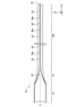
- FIG. 1 is a plan view of the inserter 1 of the first embodiment.
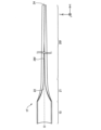
- FIG. 2 is a side view of the inserter 1.
- FIG. FIG. 3 is a cross-sectional view of the inserter 1.
- FIG. 3A shows a cross section taken along line A--A of FIGS. 1 and 2.
- FIG. 3B shows a cross section taken along line BB of FIGS. 1 and 2.
- FIG. 1 is a plan view of the inserter 1 of the first embodiment.
- FIG. 2 is a side view of the inserter 1.
- FIG. FIG. 3 is a cross-sectional view of the inserter 1.
- FIG. 3A shows a cross section taken along line A--A of FIGS. 1 and 2.
- FIG. 3B shows a cross section taken along line BB of FIGS. 1 and 2.
- the inserter 1 is an elongated instrument that assists in inserting a medical device such as a guidewire into an insertion target.
- the inserter 1 is used to assist in inserting a guidewire into a catheter to be inserted.
- the inserter 1 can be made of, for example, polyamide resin, polyolefin resin, polyester resin, polyurethane resin, silicon resin, fluorine resin, or the like.
- the inserter 1 is made of PTFE resin, which is a fluorine resin.
- the inserter 1 has a flat portion 10 and a tubular portion 20 .
- FIGS. 1 and 2 include portions in which the relative size ratios of the constituent members are different from the actual ones. In addition, it includes a portion exaggeratedly describing a part of each constituent member. 1 and 2 also show XYZ axes orthogonal to each other.
- the X-axis corresponds to the longitudinal direction of the inserter 1
- the Y-axis corresponds to the height direction of the inserter 1
- the Z-axis corresponds to the width direction of the inserter 1 .
- proximal side of the inserter 1 and each component
- distal side of the inserter 1 and each component
- base end of the longitudinal (X-axis) ends of the inserter 1 and each component member
- distal end and base end are referred to as the distal portion
- proximal end and the vicinity thereof are referred to as the “basal end portion”.
- the flat portion 10 is a portion that constitutes the base end side of the inserter 1 .
- the flat portion 10 has a flat shape as shown in FIG. 3(A). 2, the flat portion 10 is curved in a direction away from the axis O of the inserter 1 from the distal end side to the proximal end side.
- the tubular portion 20 is an elongated portion of the inserter 1 provided on the distal end side of the flat portion 10 .
- the cross-sectional shape of the cylindrical portion 20 at a position closer to the distal end than the proximal end portion 21 is cylindrical, as shown in FIG. 3(B).
- the cross-sectional shape of the inserter 1 taken along the line AA is flat, and the cross-sectional shape of the inserter 1 taken along the line BB is cylindrical. be.
- the cross-sectional shape of the cylindrical portion 20 at the proximal end portion 21 transitions from a flat shape to a cylindrical shape from the proximal end side to the distal end side.
- the cross-sectional shape of the cylindrical portion 20 at the proximal end portion 21 changes from a flat shape to a cylindrical shape that gradually curls from the proximal end side to the distal end side.
- the tubular portion 20 has a proximal opening 22 provided at the proximal end and a distal opening 24 provided at the distal end.
- a slit 26 is provided on the side surface of the cylindrical portion 20 to connect the proximal side opening 22 and the distal side opening 24 and communicate the inside and the outside of the cylindrical portion 20 .
- the width (length in the Z-axis direction) of the slit 26 is substantially constant at a position closer to the distal end than the proximal end portion 21 .
- the width of the slit 26 is designed to be shorter than the diameter of the medical device to be inserted into the inserter 1 (the medical device whose insertion into the insertion target is assisted).
- the tubular portion 20 has a first end portion 27 and a second end portion 28 facing each other across a slit 26 in any cross section. Also, the first end portion 27 and the second end portion 28 are spaced apart in the circumferential direction.
- the first end portion 27 and the second end portion 28 referred to here include the ends in the circumferential direction of the cross section and the vicinity thereof. Note that the thickness T and the maximum outer diameter ⁇ 1 will be described later.
- FIG. 4 is a perspective view for explaining the manufacturing process of the inserter 1.
- FIG. 4A is a perspective view of the intermediate product 1P.
- FIG. 4B is a perspective view of the inserter 1.
- FIG. 4A is a perspective view of the intermediate product 1P.
- the intermediate product 1P is a cylindrical member.
- the intermediate product 1P is manufactured by joining a pair of opposing sides of one sheet member to form a tubular shape.
- This sheet member is a sheet member cut out along the stretching direction from uniaxially stretched PTFE resin.
- the direction in which the PTFE resin is stretched is parallel to the direction in which the two sides that are joined when being molded into a cylindrical shape extend. That is, the longitudinal direction of the intermediate product 1P is parallel to the stretching direction of the PTFE resin forming the intermediate product 1P.
- a cut CT (illustrated by a broken line) is made in the side surface of the intermediate product 1P. At this time, the cut CT is made over the entire length of the intermediate product 1P.
- the intermediate product 1P is opened with a constant width (corresponding to the width of the slit 26) along the longitudinal direction to form the cylindrical portion 20. be done.
- the intermediate product 1P is widely opened to form a flat portion 10. As shown in FIG.
- the portion of the cylindrical portion 20 corresponding to the base end portion 21 is opened so that the cross-sectional shape changes from the flat shape to the cylindrical shape.
- the flat portion 10 and the tubular portion 20 are formed from a single sheet member, and the sheet member is formed from uniaxially stretched PTFE resin. Since the PTFE resin, which is the material used for the inserter 1 of the present embodiment, has relatively high plasticity, the shape after the manufacturing process is maintained even if the above-described manufacturing process is performed without applying heat in advance.
- the material used for the inserter 1 is a thermoplastic resin, it is preliminarily heated and then the above manufacturing process is carried out.
- the longitudinal direction of the intermediate product 1P is parallel to the stretching direction in the PTFE resin forming the intermediate product 1P.
- the slit 26 in the inserter 1 is formed along the longitudinal direction of the intermediate product 1P. Therefore, the extending direction of the PTFE resin forming the inserter 1 is parallel to the extending direction of the slit 26 extending from the proximal side opening 22 to the distal side opening 24 .
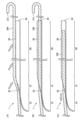
- FIG. 5 and 6 are explanatory diagrams showing the process of attaching the guide wire GW, which is a medical device, to the inserter 1.
- FIG. 5A to 5C are plan views showing a series of mounting processes.
- 6A to 6C are side views showing a series of mounting processes.
- the guide wire GW is a guide wire having a curved portion CV at its tip.
- medical devices such as guidewires are often provided with a small curved shape (hereinafter also referred to as a “curved portion”) at the tip in order to improve blood vessel selectivity.
- the operator places the portion of the guide wire GW closer to the proximal side than the curved portion CV on the slit 26 provided in the inserter 1. do. Then, the guide wire GW is pressed against the inserter 1 (slit 26) in order from the proximal side to the distal side (in the direction indicated by the white arrow). That is, the portion of the guide wire GW on the proximal side of the curved portion CV is pressed over the entire length of the slit 26 .
- the width of the slit 26 is designed to be shorter than the diameter of the guide wire GW, the slit 26 corresponding to the position where the guide wire GW is pressed is widened in the width direction so that the guide wire GW can be sequentially inserted into the inserter 1. take in.
- FIGS. 5(B) and 6(B) show a state in which the guide wire GW is inserted into the inserter 1 through the slit 26 through the process described in FIGS. 5(A) and 6(A). It is shown. A curved portion CV of the guide wire GW is exposed to the outside of the inserter 1 through the distal opening 24 . From this state, as shown in FIGS. 5(C) and 6(C), the operator pulls the guide wire GW toward the proximal end side to house the bending portion CV inside the inserter 1 (white line). direction indicated by the open arrow). Along with this retraction, the curved portion CV is corrected into a straight shape along the elongated inserter 1 .
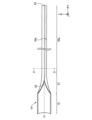
- FIG. 7 is an explanatory diagram showing a state in which the inserter 1 is inserted into the connector 50.
- FIG. 7 In the state shown in FIG. 7, after the inserter 1 maintaining the state shown in FIGS. It has been delivered and inserted into the catheter CA.
- the portion of the inserter 1 that is inserted into the connector 50 is indicated by a broken line.
- a portion of the guide wire GW that is inserted into the inserter 1 is omitted from the drawing.
- the connector 50 is a connector into which the inserter 1 is inserted. Further, the connector 50 includes a first port 51 having a hemostasis valve, a second port 52 for injecting a contrast agent or the like, and a connecting portion 53 connected to the catheter hub HB. The catheter hub HB is connected to the connecting portion 53 . Catheter CA is connected to connector 50 via catheter hub HB.
- the length L1 from the distal end of the flat portion 10 to the distal end of the cylindrical portion 20 in the inserter 1 is from the proximal end of the insertion hole of the connector 50 (the hole for inserting the cylindrical portion 20 into the connector 50) to the distal end of the catheter hub HB. It is designed to be longer than the length L2. In FIG.
- the length L1 is preferably 110 mm or more and 130 mm or less.
- the tubular portion 20 can be exposed from the distal end of the catheter hub HB and placed in the catheter CA, and the tubular portion 20 can be placed inside the catheter CA.
- Curvature CV (not shown in FIG. 7) can be delivered into catheter CA by releasing the straightening from the tip.
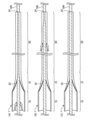
- FIG. 8A to 8C are plan views showing a series of withdrawal processes.
- 9A to 9C are side views showing a series of withdrawal processes.
- FIGS. 8(B) and 9(B) the operator moves a finger or the like sandwiched between the flat portion 10 and the guide wire GW along the surface of the inserter 1 to the distal end side.
- the guide wire GW that has been taken into the inserter 1 is pulled out from the inserter 1 by moving (in the direction indicated by the white arrow).
- 8(C) and 9(C) show a state in which the guide wire GW has been removed from the inserter 1 through the slit 26 through the process described in FIGS. 8(B) and 9(B). It is
- the proximal side opening 22 and the distal side opening 24 are connected to the side surface of the tubular section 20, and the inside and outside of the tubular section 20 are communicated.
- a slit 26 is provided. Therefore, for example, when a guide wire GW having a curved portion CV at its distal end is inserted into the inserter 1 as a medical device (see FIGS.
- the portion of the guide wire GW on the proximal side of the curved portion CV After inserting the portion (non-curved linear portion) into the inserter 1 by pressing it over the entire length of the slit 26, the guide wire GW is pulled toward the proximal end side, thereby correcting the curved portion CV into a linear shape and inserting the inserter. 1 can be stored. Therefore, such a medical device can be easily inserted into the inserter 1 as compared with the case where a medical device such as a guide wire GW having a curved portion CV at its tip is inserted from the rear end of the inserter.
- the inserter 1 includes the flat portion 10 having a flat shape, and the cross-sectional shape of the cylindrical portion 20 at the base end portion 21 is oriented from the base end side to the tip end side. It transitions from a flat shape to a cylindrical shape. Therefore, before pressing a medical device such as a guide wire GW against the slit 26, the medical device is placed on the flat portion 10 and positioned by the base end portion 21 of the cylindrical portion 20. (See FIGS. 5A and 6A).
- the slit 26 is widened in order.
- the medical device can be inserted into the inserter 1 by using the In this respect as well, according to the inserter 1 having this configuration, a medical device such as a guide wire GW can be easily inserted into the inserter 1 .
- the inserter 1 of the first embodiment when inserting the inserter 1 into a cylindrical object (for example, the connector 50 in FIG. 7), the entire inserter 1 is inserted into the object. can be prevented. Also, when holding the inserter 1 with the flat portion 10 sandwiched between two fingers, the surface of the flat portion 10 facing the opposite side to the axis side (the -Y-axis direction side in FIG. 2) Since the contact area between the curve and the curved surface of the finger surface (the ball of the finger) is increased, the inserter 1 can be easily held.
- the inserter 1 when the inserter 1 is placed on a flat surface, there is a high possibility that the periphery of the base end portion 21 of the cylindrical portion 20 of the inserter 1 will be in a state of floating from the flat surface due to the curvature of the flat portion 10. By gripping the periphery of the end portion 21, the inserter 1 placed on a flat surface can be easily picked up.
- the inserter 1 when the inserter 1 is arranged on a mount having a surface formed with a curved surface for receiving the curvature of the flat portion 10, the inserter 1 can be stably arranged.
- the first end portion 27 and the second end portion 28 are spaced apart in the circumferential direction. Therefore, the medical device can be easily fitted into the slit 26 from the outside of the inserter 1 , and the medical device can be easily positioned by the slit 26 . In addition, the force required to widen the width of the slit 26 by pressing the medical device (widening to the extent that the medical device can be inserted into the inserter 1) can be reduced.
- the manufacturing process of the inserter 1 can be labor-saving as compared with the case where the inserter 1 is manufactured by connecting the flat portion 10 and the cylindrical portion 20 which are formed of separate members. can be In addition, since there is no connecting portion due to connecting members, the inserter 1 that is difficult to break can be realized.
- the sheet member constituting the inserter 1 is made of uniaxially stretched PTFE resin.
- a sheet member is cut out from uniaxially stretched PTFE resin, and the inserter 1 is formed from the sheet member.
- the molecules in the resin are oriented along the stretching direction, so cutting out the sheet member along the stretching direction facilitates and speeds up the cutting operation. Therefore, the manufacturing efficiency of the inserter 1 can be improved.
- the stretching direction of the PTFE resin (in the sheet member) is parallel to the stretching direction of the slits 26 extending from the proximal side opening to the distal side opening. For this reason, it is possible to realize the inserter 1 in which cracks in the direction orthogonal to the extending direction of the slits 26 are less likely to occur.
- FIG. 10 shows the results of an evaluation test that evaluated the feeling of use when a guidewire was inserted into each inserter 1 (Examples 1 to 12 and Comparative Examples 1 to 5) prepared by adjusting various parameters. is shown as a table.
- the various parameters referred to here include the minimum width W of the slit 26, the thickness T of the inserter 1 (see FIG. 3B), and the maximum outer diameter ⁇ 1 of the tubular portion 20 (see FIG. 3B). , is included.
- the minimum width W is the width of the slit 26 at the minimum width. It can also be said that the thickness T is the thickness of the sheet member forming the inserter 1 .
- the maximum outer diameter ⁇ 1 is the outer diameter at the position where the outer diameter is maximum in the cross section of the tubular portion 20 .
- the width of the slit 26 and the outer diameter of the tubular portion 20 are generally constant.
- guidewire diameter indicates the diameter of the guidewire inserted into the inserter 1.
- Minimum width W indicates the minimum width W of the slit 26 .
- Thiickness T indicates the thickness T of the inserter 1 .
- Maximum outer diameter ⁇ 1 indicates the maximum outer diameter ⁇ 1 of the tubular portion 20 .
- the “clearance width C” indicates the clearance width C obtained by subtracting the maximum outer diameter ⁇ 1 of the cylindrical portion 20 from the maximum inner diameter of the insertion hole of the connector 50 (the hole for inserting the cylindrical portion 20 into the connector 50).
- the maximum inner diameter is the inner diameter of the portion of the connector 50 where the inserter 1 is inserted, at the position where the inner diameter is the largest, and is 2.65 mm in FIG.
- the unit of the numerical value on the left side of the numerical values indicating "guidewire diameter” is inches, and the numerical value in parentheses on the right side is the numerical value obtained by converting the numerical value on the left side into millimeters, and the unit is millimeters.
- the unit of numerical values indicating the "minimum width W", “thickness T”, “maximum outer diameter ⁇ 1", and “clearance width C" is millimeters.
- Fig. 10 shows evaluation items for usability.
- Connector insertability indicates ease of inserting the inserter 1 into the connector 50 .
- the "slit formability” indicates the easiness of cutting in the manufacturing process of the inserter 1, when the side surface of the intermediate product 1P is cut CT (see FIG. 4(A)).
- Slit release indicates how difficult it is for the curved portion to protrude from the slit 26 when a guide wire having a curved portion at its tip is inserted into the inserter 1 (see FIGS. 5 and 6).
- Kink resistance indicates the difficulty of clogging the lumen of the inserter 1 when the inserter 1 is bent during the process of inserting the inserter 1 into the connector 50 (see FIG. 7).
- “Detachability” indicates ease of inserting a guidewire into the inserter 1 and ease of removing the guidewire from the inserter 1 .
- Each evaluation item of feeling in use was evaluated in three grades of B, C, and D.
- the "comprehensive evaluation” is a comprehensive evaluation in consideration of the evaluation items of each usability, and was evaluated in four stages of A, B, C, and D.
- the evaluation result means that A is the best and D is the worst.
- each "overall evaluation” was D.
- each "connector insertability” was evaluated as D, which is considered to be due to the numerical value of each "clearance width C" being 0.00 mm.
- the evaluation of "missing slit” was D, which is considered to be due to the numerical value of "minimum width W" being 0.7 mm.
- the evaluation of "kink resistance” was D, which is considered to be due to the numerical value of "clearance width C" being 0.55 mm.
- the minimum width W of the slit is 0.2 mm or more and 0.9 mm or more. It is 6 mm or less, and the thickness T of the inserter 1 is preferably 0.2 mm or more and 0.5 mm or less.
- the guide wire when assisting the insertion of a medical device such as a guide wire having a diameter of 0.6 mm or more and 0.9 mm or less, the guide wire can be easily inserted into the inserter 1 and It is possible to realize an inserter from which the medical device can be easily removed. Further, when assisting the insertion of a medical device such as a guide wire having a curved portion at its distal end, the inserter 1 can be realized in which the curved portion is less likely to protrude from the slit. That is, it is possible to realize an inserter excellent in "detachability" and "slit removal".
- the minimum width W of the slit is more preferably 0.3 mm or more and 0.4 mm or less. According to this configuration, when assisting the insertion of a medical device such as a guide wire having a diameter of 0.6 mm or more and 0.9 mm or less and having a curved portion at the distal end, the curved portion is less likely to protrude from the slit 26.
- the inserter 1 can be implemented.
- the clearance width C is preferably 0.10 mm or more and 0.35 mm or less. This configuration makes it easier to insert the inserter 1 into the connector 50 . That is, it is possible to realize an inserter excellent in "connector insertability" and "kink resistance”.
- the inserter 1 when the length L2 is 110 mm, the length L1 from the tip of the flat portion 10 to the tip of the tubular portion 20 in the inserter 1 is 110 mm or more and 130 mm or less. is preferred.
- the inserter accommodates the medical device with the curved portion straightened. 1 is inserted into a cylindrical object (connector 50 in FIG. 7) (see FIGS. 5 to 7), a position (the tip of cylindrical portion 20) separated from the tip of flat portion 10 by 110 mm or more and 130 mm or less.
- the straightening can be released from and the curved portion can be delivered.
- the bending portion CV (not shown in FIG. 7) can be delivered from the distal end of the tubular portion 20 placed in the catheter CA with the straightening removed.
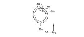
- FIG. 11 is a plan view of the inserter 1A of the second embodiment.
- FIG. 12 is a cross-sectional view of the inserter 1A.
- FIG. 12 shows a cross section taken along line CC of FIG.
- the inserter 1A of the second embodiment differs from the inserter 1 of the first embodiment in that it has a tubular portion 20a different from the tubular portion 20 of the first embodiment.
- the tubular portion 20a has a first end portion 27a and a second end portion 28a that face each other with a slit 26a interposed therebetween and overlap each other in any cross section.
- first end portion 27 and the second end portion 28 are spaced apart in the circumferential direction (see FIG. 3B), in the plan view (FIG. 1), the cylinder
- first end 27a and the second end 28a overlap each other (see FIG. 12), so the plan view (FIG. 11 ), the inside of the cylindrical portion 20 cannot be visually recognized.
- the width of the slit 26a is widened so that the medical device can be inserted into the inserter 1A. be able to.
- the inserter 1A of the second embodiment As described above, it is possible to easily insert a medical device such as a guidewire into the inserter 1A as in the first embodiment. Further, according to the inserter 1A of the second embodiment, when the medical device is inserted into the inserter 1A, the entire periphery of the medical device is covered by the inserter 1A. can be prevented from popping out.
- FIG. 13 is a plan view of the inserter 1B of the third embodiment.
- the inserter 1B of the third embodiment differs from the inserter 1 of the first embodiment in that it has a tubular portion 20b different from the tubular portion 20 of the first embodiment.
- the width (the length in the Z-axis direction) of the slit 26b provided in the tubular portion 20b is approximately although it has a constant width, it gradually narrows toward the tip at the tip.
- a medical device such as a guide wire can be easily inserted into the inserter 1B as in the first embodiment.
- a medical device can be easily fitted from the outside of the inserter 1B into a portion of the slit 26b that has a substantially constant width (excluding the tip portion). device is easier to position.
- the tip of the slit 26b can prevent the medical device from popping out of the inserter 1B.
- FIG. 14 is a plan view of the inserter 1C of the fourth embodiment.
- the inserter 1C of the fourth embodiment differs from the inserter 1 of the first embodiment in that it has a tubular portion 20c different from the tubular portion 20 of the first embodiment.
- the width (the length in the Z-axis direction) of the slit 26c provided in the cylindrical portion 20c gradually narrows from the proximal side opening 22 toward the distal side opening 24.
- a medical device such as a guide wire can be easily inserted into the inserter 1C as in the first embodiment.
- FIG. 15 is a plan view of the inserter 1D of the fifth embodiment.
- the inserter 1D of the fifth embodiment differs from the inserter 1 of the first embodiment in that it has a tubular portion 20d different from the tubular portion 20 of the first embodiment.
- the width (the length in the Z-axis direction) of the slit 26d provided in the cylindrical portion 20d is the same as in the fourth embodiment, from the proximal side opening 22 to the distal side opening. 24 gradually becomes narrower.
- a first end (not shown) and a second end (not shown) overlap each other.
- FIG. 16 is a plan view of the inserter 1E of the sixth embodiment.
- the inserter 1E of the sixth embodiment differs from the inserter 1 of the first embodiment in that it has a tubular portion 20e different from the tubular portion 20 of the first embodiment.
- bridge portions 29 are provided at regular intervals in the slits 26e provided in the cylindrical portion 20e.
- the slit 26e does not connect the proximal-side opening 22 and the distal-side opening 24 on the side surface of the cylindrical portion 20e, and a bridging portion is formed between the proximal-side opening 22 and the distal-side opening 24. 29 are provided alternately. Even in such a cylindrical portion 20e, when a medical device such as a guide wire is pressed against the slit 26e, the cross-linking portion 29 is destroyed and then the slit 26e is widened so that the medical device can be inserted into the inserter 1E.
- the inserter 1E of the sixth embodiment As described above, it is possible to easily insert a medical device such as a guidewire into the inserter 1E as in the first embodiment.
- a medical device such as a guidewire
- the inserter 1E of the sixth embodiment since the bridging portion 29 is provided, the cylindrical portion 20e is deformed by an external force, and the diameter of the cylindrical portion 20e (the width of the slit 26e) changes when manufacturing is completed. can be prevented from shrinking from the inserter 1E.
- remnants of the bridging portion 29 remain on at least one end of the slit 26e in the width direction (the Z-axis direction in FIG. 16).
- the medical device is inside the inserter 1E, it is possible to prevent the medical device from popping out of the inserter 1E due to the wreckage.
- FIG. 17 is a plan view of the inserter 1F of the seventh embodiment.
- the inserter 1F of the seventh embodiment differs from the inserter 1 of the first embodiment in that it has a tubular portion 20f different from the tubular portion 20 of the first embodiment.
- the width (the length in the Z-axis direction) of the slit 26f provided in the cylindrical portion 20f is the same as in the fourth embodiment, from the proximal side opening 22 to the distal side opening. 24 gradually becomes narrower.
- a first end (not shown) and a second end ( (not shown) overlap each other.
- the diameter of the cylindrical portion 20f is reduced from the proximal side to the distal side.
- FIG. 18 is a plan view of the inserter 1G of the eighth embodiment.
- the inserter 1G of the eighth embodiment differs from the inserter 1 of the first embodiment in that it has a tubular portion 20g different from the tubular portion 20 of the first embodiment.
- the tubular portion 20g has the smallest diameter portion 23 at the tip.
- the smallest diameter portion 23 is a portion of the cylindrical portion 20g that has a smaller diameter than the portion on the base end side from the smallest diameter portion 23 .
- the smallest diameter portion 23 may be produced by extending the tip portion of the cylindrical portion 20 along the axis O using the inserter 1 of the first embodiment.
- the inserter 1G may be manufactured by press molding using a mold for molding the inserter 1G. With such an inserter 1G of the eighth embodiment as well, a medical device such as a guide wire can be easily inserted into the inserter 1G as in the first embodiment.
- the inserter 1G since the tubular portion 20g has the reduced diameter portion 25, the inserter 1G (tubular portion 20g) can be inserted into the catheter CA via the connector 50 (FIG. 7). When providing guidance, the guidance can be performed smoothly.
- FIG. 19 is a plan view of the inserter 1H of the ninth embodiment.
- the inserter 1H of the ninth embodiment differs from the inserter 1G of the eighth embodiment in that it has a tubular portion 20h different from the tubular portion 20g of the eighth embodiment.
- the tubular portion 20h has a reduced diameter portion 25 at the base end portion of the smallest diameter portion 23.
- the reduced-diameter portion 25 is a portion of the cylindrical portion 20h whose diameter gradually decreases toward the distal end side.
- the reduced diameter portion 25 and the smallest diameter portion 23 may be produced by extending the tip portion of the inserter 1 along the axis O, as in the eighth embodiment.
- the inserter 1H may be manufactured by press molding using a mold for molding the inserter 1H. With such an inserter 1H of the ninth embodiment as well, a medical device such as a guide wire can be easily inserted into the inserter 1G like the first embodiment.
- the inserter 1H of the ninth embodiment since the cylindrical portion 20h has the smallest diameter portion 23 and the reduced diameter portion 25, the inserter 1H (cylindrical portion 20h) is connected via the connector 50 (FIG. 7). ) into the catheter CA, the guidance can be performed more smoothly.
- the configurations of the inserters 1, 1A to 1H are illustrated.
- the configuration of the inserter can be modified in various ways.
- the flat portion 10 is curved in a direction away from the axis O of the inserter 1 from the distal end side to the proximal end side. It may be along the axis O.
- the flat portion 10 and the tubular portion 20 may not be formed from a single sheet member, and the flat portion 10 and the tubular portion 20 formed from separate members are connected to form the inserter 1. You may have Further, even if the flat portion 10 and the cylindrical portion 20 are formed from one sheet member, the sheet member may be formed from PTFE resin that is not uniaxially stretched.
- the inserter 1 was described as an inserter used to assist in inserting a guide wire into a catheter, but the present invention is not limited to this, and any medical device (catheter, tube, etc.) can be used in any desired manner. It may also be used to aid insertion into tubular objects (blood vessels, endoscope channels, etc.).
- the color of the inserter is set according to the cylindrical object into which the inserter is inserted and the surrounding conditions assumed when the inserter is used. For example, by setting the color of the inserter to be different from the color of the sheets spread on the bed on which the patient is lying or the color of the cylindrical object, it is possible to prevent the operator from losing sight of the inserter.
Landscapes
- Health & Medical Sciences (AREA)
- Life Sciences & Earth Sciences (AREA)
- Biophysics (AREA)
- Pulmonology (AREA)
- Engineering & Computer Science (AREA)
- Anesthesiology (AREA)
- Biomedical Technology (AREA)
- Heart & Thoracic Surgery (AREA)
- Hematology (AREA)
- Animal Behavior & Ethology (AREA)
- General Health & Medical Sciences (AREA)
- Public Health (AREA)
- Veterinary Medicine (AREA)
- Media Introduction/Drainage Providing Device (AREA)
Abstract
The present invention is an inserter for assisting insertion of a medical device, the inserter being provided with a flat part having a flat shape, and a long cylindrical part provided on the distal end side relative to the flat part. The cylindrical part has a base-end-side opening provided to the base end thereof and a distal-end-side opening provided to the distal end thereof. A slit that connects the base-end-side opening and the distal-end-side opening and that communicates between the interior and the exterior of the cylindrical part is provided to the side surface of the cylindrical part. The minimum width of the slit is 0.2-0.6 mm inclusive, and the thickness of the inserter is 0.2-0.5 mm inclusive.
Description
本発明は、インサータや、ガイドワイヤキット、及びカテーテルキットに関する。
The present invention relates to inserters, guidewire kits, and catheter kits.
従来、ガイドワイヤ等の医療用デバイスを挿入対象へ挿入する場合に、挿入を補助するインサータを用いることがある。そのようなインサータには、例えば、ガイドワイヤを挿入対象であるカテーテルに挿入する際の補助に用いられるインサータがある。特許文献1には、カテーテルを血管へ挿入する際の補助に用いられるインサータとして、カテーテル導入装置が開示されている。特許文献2には、チューブを内視鏡のチャンネルへ挿入する際の補助に用いられるインサータとして、内視鏡用挿入補助具が開示されている。
Conventionally, when inserting a medical device such as a guide wire into an insertion target, an inserter is sometimes used to assist the insertion. Such inserters include, for example, inserters used to assist in inserting a guidewire into a catheter to be inserted. Patent Literature 1 discloses a catheter introduction device as an inserter used to assist in inserting a catheter into a blood vessel. Patent Literature 2 discloses an endoscope insertion aid as an inserter used to assist in inserting a tube into a channel of an endoscope.
特許文献1に開示されたインサータにおいては、インサータの先端が血管内に配置された状態において、インサータの後端からカテーテルを挿入して先端から送り出すことにより、カテーテルが血管内に挿入される。このような形状のインサータを用いて、挿入対象としてのカテーテルに対して、ガイドワイヤ等の医療用デバイスを挿入する場合について考える。ガイドワイヤ等の医療用デバイスは、血管選択性を向上させるために、先端に小さな湾曲形状(以降「湾曲部」とも呼ぶ)が付されることが多い。このような湾曲部を有する医療用デバイスでは、湾曲部が妨げとなることで、インサータの後端から医療用デバイスを挿入する際の作業が煩雑になり、手技の遅延や医療用デバイスの先端部の破損を招くという課題があった。なお、特許文献2に開示されたインサータでは、インサータの側面からインサータ内にチューブが挿入されて使用されることから、インサータの後端からの挿入については何ら考慮されていない。
In the inserter disclosed in Patent Document 1, the catheter is inserted into the blood vessel by inserting the catheter from the rear end of the inserter and sending it out from the tip while the tip of the inserter is placed in the blood vessel. Consider a case where an inserter having such a shape is used to insert a medical device such as a guide wire into a catheter to be inserted. A medical device such as a guidewire is often provided with a small curved shape (hereinafter also referred to as a “curved portion”) at its tip in order to improve blood vessel selectivity. In a medical device having such a curved portion, the curved portion interferes with the operation of inserting the medical device from the rear end of the inserter. There was a problem of causing damage to the In addition, in the inserter disclosed in Patent Document 2, since the tube is inserted into the inserter from the side surface of the inserter for use, insertion from the rear end of the inserter is not considered at all.
本発明は、上述した課題を解決するためになされたものであり、先端に湾曲部を有する医療用デバイスを容易に挿入することができるインサータ、ガイドワイヤキット及びカテーテルキットを提供することを目的とする。
SUMMARY OF THE INVENTION The present invention has been made to solve the above-described problems, and an object of the present invention is to provide an inserter, a guide wire kit, and a catheter kit that allow easy insertion of a medical device having a curved tip. do.
本発明は、上述の課題の少なくとも一部を解決するためになされたものであり、以下の形態として実現することが可能である。
The present invention has been made to solve at least part of the above problems, and can be implemented as the following forms.
(1)本発明の一形態によれば、インサータが提供される。このインサータは、医療用デバイスの挿入を補助するインサータであって、偏平形状を有する偏平部と、前記偏平部よりも先端側に設けられた長尺状の筒状部と、を備え、前記筒状部は、基端に設けられた基端側開口と、先端に設けられた先端側開口と、を有し、前記筒状部の側面には、前記基端側開口と前記先端側開口とを接続するとともに、前記筒状部の内外を連通するスリットが設けられており、基端部における前記筒状部の横断面形状は、基端側から先端側に向かって偏平形状から筒状へと遷移している。
(1) According to one aspect of the present invention, an inserter is provided. This inserter is an inserter for assisting insertion of a medical device, and includes a flat portion having a flat shape, and an elongated cylindrical portion provided on the distal end side of the flat portion. The shaped portion has a proximal side opening provided at the proximal end and a distal side opening provided at the distal end, and the proximal side opening and the distal side opening are provided on the side surface of the cylindrical portion. and a slit that communicates the inside and outside of the tubular portion. and is transitioning.
この構成によれば、インサータが備える筒状部の側面には、基端側開口と先端側開口とを接続するとともに筒状部の内外を連通するスリットが設けられている。このため、医療用デバイスとして、例えば、先端に湾曲部を有するガイドワイヤをインサータに挿入する場合に、ガイドワイヤのうち湾曲部より基端側の部分(湾曲していない直線状部分)をスリットの全長にわたって押し当ててインサータ内に挿入したのち、ガイドワイヤを基端側に引っ張ることにより、湾曲部を直線形状に矯正してインサータ内に収納することができる。したがって、先端に湾曲部を有するガイドワイヤ等の医療用デバイスをインサータの後端から挿入する場合と比べて、医療用デバイスをインサータ内に容易に挿入することができる。また、この構成によれば、インサータは、偏平形状を有する偏平部を備え、基端部における筒状部の横断面形状は、基端側から先端側に向かって偏平形状から筒状へと遷移している。このため、ガイドワイヤ等の医療用デバイスをスリットに押し当てる前に、医療用デバイスを偏平部の上に載置するとともに、筒状部の基端部によって医療用デバイスを位置決めすることができる。したがって、インサータに対して医療用デバイスが位置決めされている状態で、筒状部の基端部から先端に向かって医療用デバイスをスリットに押し当てることにより、スリットが順に拡幅されて医療用デバイスをインサータ内へ挿入することができる。このような点においても、この構成のインサータによれば、医療用デバイスをインサータ内に容易に挿入することができる。
According to this configuration, the side surface of the cylindrical portion of the inserter is provided with a slit that connects the proximal side opening and the distal side opening and that communicates the inside and outside of the cylindrical portion. Therefore, as a medical device, for example, when a guide wire having a curved portion at its distal end is inserted into an inserter, a portion of the guide wire on the proximal side of the curved portion (a linear portion that is not curved) is cut into a slit. After inserting the guide wire into the inserter while pressing it over its entire length, the curved portion can be straightened and stored in the inserter by pulling the guide wire toward the proximal end side. Therefore, the medical device can be easily inserted into the inserter as compared with the case where a medical device such as a guide wire having a curved portion at the distal end is inserted from the rear end of the inserter. In addition, according to this configuration, the inserter includes a flat portion having a flat shape, and the cross-sectional shape of the cylindrical portion at the proximal end transitions from the flat shape to the cylindrical shape from the proximal end to the distal end. are doing. Therefore, before pressing a medical device such as a guide wire against the slit, the medical device can be placed on the flat portion and positioned by the base end portion of the cylindrical portion. Therefore, in a state where the medical device is positioned with respect to the inserter, by pressing the medical device against the slit from the base end portion to the tip end of the cylindrical portion, the width of the slit is widened in order to remove the medical device. It can be inserted into an inserter. In this respect as well, according to the inserter with this configuration, the medical device can be easily inserted into the inserter.
(2)上記形態のインサータにおいて、前記偏平部は、先端側から基端側に向かって前記インサータの軸線から離れる方向に湾曲していてもよい。
この構成によれば、インサータを筒状の対象物に挿入する場合に、その対象物内にインサータ全体が挿入されることを防止できる。また、2本の指で偏平部を挟んでインサータを保持する場合において、偏平部の面のうち軸線側とは反対側を向いている面の湾曲と指表面の曲面(指の腹)との接触面積が大きくなることから、インサータを保持しやすくすることができる。また、インサータを平面に載置している際、インサータのうち筒状部の基端部周辺が偏平部の湾曲により平面から浮いた状態になる可能性が高いことから、基端部周辺を掴むことによって、平面に載置している状態のインサータを拾い上げやすくすることができる。また、偏平部の湾曲を受ける曲面が表面に形成された台紙を用いて、その台紙の上にインサータを配置する場合に、インサータを安定して配置することができる。 (2) In the inserter of the above aspect, the flat portion may be curved in a direction away from the axis of the inserter from the distal side to the proximal side.
According to this configuration, when inserting the inserter into a cylindrical object, it is possible to prevent the entire inserter from being inserted into the object. Also, when holding the inserter by holding the flat portion between two fingers, the curvature of the surface of the flat portion facing the opposite side to the axis line side and the curved surface of the finger surface (finger ball) Since the contact area is increased, the inserter can be easily held. Also, when the inserter is placed on a flat surface, there is a high possibility that the periphery of the base end of the cylindrical portion of the inserter will be in a state of floating from the plane due to the curvature of the flat portion. As a result, the inserter placed on the flat surface can be easily picked up. In addition, when the inserter is placed on the backing paper having a curved surface that receives the curvature of the flat portion, the inserter can be stably placed.
(3)上記形態のインサータにおいて、前記筒状部は、任意の横断面において、前記スリットを挟んで向かい合う第1端部と第2端部とを有しており、前記第1端部と前記第2端部とは周方向に離間していてもよい。
この構成によれば、第1端部と第2端部とは周方向に離間している。このため、インサータの外部から医療用デバイスがスリットに嵌まりやすいことから、スリットによって医療用デバイスが位置決めされやすくなる。また、医療用デバイスの押し当てによるスリットの拡幅(インサータ内への医療用デバイスの挿入が可能となる程度の拡幅)に要する力を低減することができる。 (3) In the inserter of the above aspect, the cylindrical portion has a first end and a second end facing each other across the slit in any cross section, and the first end and the It may be circumferentially spaced apart from the second end.
According to this configuration, the first end and the second end are spaced apart in the circumferential direction. Therefore, the medical device can be easily fitted into the slit from the outside of the inserter, and the medical device can be easily positioned by the slit. In addition, it is possible to reduce the force required to widen the slit by pressing the medical device (widening to the extent that the medical device can be inserted into the inserter).
(4)上記形態のインサータにおいて、前記筒状部は、任意の横断面において、前記スリットを挟んで向かい合う第1端部と第2端部とを有しており、前記第1端部と前記第2端部とは重なり合っていてもよい。
この構成によれば、第1端部と第2端部とは重なり合っている。このため、医療用デバイスがインサータ内に挿入された状態において、医療用デバイスはインサータにより全周にわたって覆われていることから、インサータから医療用デバイスが飛び出すことを防止できる。 (4) In the inserter of the above aspect, the cylindrical portion has a first end and a second end facing each other across the slit in any cross section, and the first end and the It may overlap with the second end.
According to this configuration, the first end and the second end overlap each other. Therefore, when the medical device is inserted into the inserter, the entire periphery of the medical device is covered by the inserter, thereby preventing the medical device from popping out of the inserter.
(5)上記形態のインサータにおいて、前記偏平部及び前記筒状部は、1枚のシート部材から形成されていてもよい。
この構成によれば、それぞれ別の部材から形成された偏平部及び筒状部を連結してインサータを製造する場合と比べて、インサータの製造工程を省力化することができる。また部材同士を連結したことによる連結部分がないことから、破断しにくいインサータを実現することができる。 (5) In the inserter of the above aspect, the flat portion and the cylindrical portion may be formed from one sheet member.
According to this configuration, the manufacturing process of the inserter can be labor-saving as compared with the case where the inserter is manufactured by connecting the flat portion and the cylindrical portion formed from separate members. In addition, since there is no connecting portion due to connecting members, it is possible to realize an inserter that is difficult to break.
(6)上記形態のインサータにおいて、前記シート部材は、一軸延伸されたPTFE樹脂により形成され、前記PTFE樹脂の延伸方向は、前記基端側開口から前記先端側開口まで延びる前記スリットの延伸方向と平行であってもよい。
この構成によれば、シート部材は、一軸延伸されたPTFE樹脂により形成される。インサータの製造工程においては、一軸延伸されたPTFE樹脂からシート部材が切り出され、そのシート部材からインサータが形成される。一軸延伸されたPTFE樹脂では、樹脂中の分子が延伸方向に沿って配向していることから、その延伸方向に沿ってシート部材を切り出すことにより、切り出し作業を容易且つ迅速に進めることができる。したがって、インサータの製造効率を向上することができる。また、この構成によれば、(シート部材中の)PTFE樹脂の延伸方向は、基端側開口から先端側開口まで延びるスリットの延伸方向と平行である。このため、スリットの延伸方向と直交する方向への裂け目が生じにくいインサータを実現することができる。 (6) In the inserter of the above aspect, the sheet member is made of uniaxially stretched PTFE resin, and the stretching direction of the PTFE resin is the same as the stretching direction of the slit extending from the proximal opening to the distal opening. They may be parallel.
According to this configuration, the sheet member is made of uniaxially stretched PTFE resin. In the inserter manufacturing process, a sheet member is cut out from uniaxially stretched PTFE resin, and the inserter is formed from the sheet member. In a uniaxially stretched PTFE resin, the molecules in the resin are oriented along the stretching direction, so cutting out the sheet member along the stretching direction facilitates and speeds up the cutting operation. Therefore, it is possible to improve the manufacturing efficiency of the inserter. Further, according to this configuration, the stretching direction of the PTFE resin (in the sheet member) is parallel to the stretching direction of the slit extending from the base end side opening to the tip side opening. Therefore, it is possible to realize an inserter in which cracks are less likely to occur in the direction orthogonal to the extending direction of the slit.
(7)また、本発明の別の一形態によれば、インサータが提供される。このインサータは、医療用デバイスの挿入を補助するインサータであって、偏平形状を有する偏平部と、前記偏平部よりも先端側に設けられた長尺状の筒状部と、を備え、前記筒状部は、基端に設けられた基端側開口と、先端に設けられた先端側開口と、を有し、前記筒状部の側面には、前記基端側開口と前記先端側開口とを接続するとともに、前記筒状部の内外を連通するスリットが設けられており、前記スリットの最小幅は、0.2mm以上かつ0.6mm以下であり、前記インサータの厚さは、0.2mm以上かつ0.5mm以下である。
この構成によれば、インサータが備える筒状部の側面には、基端側開口と先端側開口とを接続するとともに筒状部の内外を連通するスリットが設けられている。このため、医療用デバイスとして、例えば、先端に湾曲部を有するガイドワイヤをインサータに挿入する場合に、そのガイドワイヤのうち湾曲部より基端側の部分(湾曲していない直線状部分)をスリットの全長にわたって押し当ててインサータ内に挿入したのち、ガイドワイヤを基端側に引っ張ることにより、湾曲部を直線形状に矯正してインサータ内に収納することができる。したがって、先端に湾曲部を有するガイドワイヤ等の医療用デバイスをインサータの後端から挿入する場合と比べて、そのような医療用デバイスをインサータ内に容易に挿入することができる。また、この構成によれば、スリットの最小幅は、0.2mm以上かつ0.6mm以下であり、インサータの厚さは、0.2mm以上かつ0.5mm以下である。このため、0.6mm以上かつ0.9mm以下の直径を有するガイドワイヤ等の医療用デバイスの挿入を補助する場合に、インサータ内へ医療用デバイスが挿入しやすく、かつ、インサータから医療用デバイスを抜去しやすいインサータを実現することができる。また、先端に湾曲部を有する医療用デバイスの挿入を補助する場合には、スリットから湾曲部が飛び出しにくいインサータを実現することができる。 (7) According to another aspect of the invention, an inserter is provided. This inserter is an inserter for assisting insertion of a medical device, and includes a flat portion having a flat shape, and an elongated cylindrical portion provided on the distal end side of the flat portion. The shaped portion has a proximal side opening provided at the proximal end and a distal side opening provided at the distal end, and the proximal side opening and the distal side opening are provided on the side surface of the cylindrical portion. and connecting the inside and outside of the tubular portion, the minimum width of the slit is 0.2 mm or more and 0.6 mm or less, and the thickness of the inserter is 0.2 mm. not less than 0.5 mm and not more than 0.5 mm.
According to this configuration, the side surface of the cylindrical portion of the inserter is provided with a slit that connects the proximal side opening and the distal side opening and communicates the inside and the outside of the cylindrical portion. Therefore, as a medical device, for example, when a guide wire having a curved portion at its distal end is inserted into an inserter, a portion of the guide wire on the proximal side of the curved portion (a linear portion that is not curved) is slit. After inserting the guide wire into the inserter by pressing it over the entire length of the guide wire, the curved portion can be straightened and stored in the inserter by pulling the guide wire toward the proximal end side. Therefore, such a medical device can be easily inserted into the inserter as compared with the case where a medical device such as a guide wire having a curved tip is inserted from the rear end of the inserter. Further, according to this configuration, the minimum width of the slit is 0.2 mm or more and 0.6 mm or less, and the thickness of the inserter is 0.2 mm or more and 0.5 mm or less. Therefore, when assisting the insertion of a medical device such as a guide wire having a diameter of 0.6 mm or more and 0.9 mm or less, the medical device can be easily inserted into the inserter, and the medical device can be removed from the inserter. It is possible to realize an inserter that is easy to remove. Further, when assisting the insertion of a medical device having a curved portion at its tip, an inserter in which the curved portion is less likely to protrude from the slit can be realized.
(8)上記形態のインサータにおいて、前記スリットの最小幅は、0.3mm以上かつ0.4mm以下であってもよい。
この構成によれば、0.6mm以上かつ0.9mm以下の直径を有するとともに先端に湾曲部を有する医療用デバイスの挿入を補助する場合に、スリットから湾曲部が一層飛び出しにくいインサータを実現することができる。 (8) In the inserter of the above aspect, the minimum width of the slit may be 0.3 mm or more and 0.4 mm or less.
According to this configuration, when assisting the insertion of a medical device having a diameter of 0.6 mm or more and 0.9 mm or less and having a curved portion at the distal end, it is possible to realize an inserter in which the curved portion is less likely to protrude from the slit. can be done.
(9)上記形態のインサータにおいて、前記偏平部の先端から前記筒状部の先端までの長さは、110mm以上かつ130mm以下であってもよい。
この構成によれば、先端に湾曲部を有する医療用デバイスの挿入を補助する場合において、湾曲部が直線形状に矯正された状態で医療用デバイスを収納しているインサータを筒状の対象物に挿入したのち、偏平部の先端から110mm以上かつ130mm以下だけ離れた位置(筒状部の先端)から矯正を解除して湾曲部を送り出すことができる。 (9) In the inserter of the above aspect, the length from the tip of the flat portion to the tip of the tubular portion may be 110 mm or more and 130 mm or less.
According to this configuration, when assisting the insertion of a medical device having a curved portion at its distal end, the inserter housing the medical device with the curved portion corrected to a straight shape is inserted into the cylindrical object. After the insertion, the curved portion can be released from the position (tip of the cylindrical portion) separated from the tip of the flat portion by 110 mm or more and 130 mm or less.
(10)上記形態のインサータにおいて、前記スリットの幅は、前記基端側開口から前記先端側開口に向かうにつれて徐々に狭くなっていてもよい。
この構成によれば、筒状部のうち先端側に向かうほどインサータ内から医療用デバイスを飛び出しにくくすることができる。 (10) In the inserter of the above aspect, the width of the slit may gradually narrow from the proximal side opening toward the distal side opening.
According to this configuration, it is possible to make it more difficult for the medical device to protrude from the inserter toward the distal end side of the tubular portion.
(11)また、本発明の別の一形態によれば、ガイドワイヤキットが提供される。このガイドワイヤキットは、上記形態に記載のインサータと、前記医療用デバイスとしてのガイドワイヤと、を備え、前記ガイドワイヤの直径は、0.6mm以上かつ0.9mm以下である。
このガイドワイヤキットによれば、上記インサータと同様に、ガイドワイヤ等の医療用デバイスを容易に挿入することができる。 (11) According to another aspect of the present invention, a guidewire kit is provided. This guidewire kit includes the inserter according to the above aspect and a guidewire as the medical device, and the guidewire has a diameter of 0.6 mm or more and 0.9 mm or less.
According to this guidewire kit, a medical device such as a guidewire can be easily inserted in the same manner as the inserter.
(12)また、本発明の別の一形態によれば、カテーテルキットが提供される。このカテーテルキットは、上記形態に記載のインサータと、前記インサータが挿入されるコネクタと、前記コネクタが接続されるカテーテルと、を備え、前記コネクタの挿入孔の最大内径から、前記インサータの前記筒状部の最大外径を減じたクリアランス幅は、0.10mm以上かつ0.35mm以下である。
このカテーテルキットによれば、上記インサータと同様に、先端に湾曲部を有する医療用デバイスを容易に挿入することができる。また、インサータをコネクタに挿入しやすくすることができる。 (12) Further, according to another aspect of the present invention, a catheter kit is provided. This catheter kit includes an inserter according to the above aspect, a connector into which the inserter is inserted, and a catheter to which the connector is connected. The clearance width obtained by subtracting the maximum outer diameter of the portion is 0.10 mm or more and 0.35 mm or less.
According to this catheter kit, like the inserter, a medical device having a curved tip can be easily inserted. Also, the inserter can be easily inserted into the connector.
なお、本発明は、種々の態様で実現することが可能であり、例えば、インサータと、ガイドワイヤと、を備えたガイドワイヤセット、インサータと、コネクタを有するカテーテルと、を備えたカテーテルキット、インサータの製造方法などの形態で実現することができる。
It should be noted that the present invention can be implemented in various ways, for example, a guide wire set comprising an inserter and a guide wire, a catheter kit comprising an inserter and a catheter having a connector, an inserter It can be realized in the form of a manufacturing method of
<第1実施形態>
図1は、第1実施形態のインサータ1の平面図である。図2は、インサータ1の側面図である。図3は、インサータ1の横断面図である。図3(A)は、図1及び図2のA―A線における横断面を示している。図3(B)は、図1及び図2のB―B線における横断面を示している。 <First Embodiment>
FIG. 1 is a plan view of theinserter 1 of the first embodiment. FIG. 2 is a side view of the inserter 1. FIG. FIG. 3 is a cross-sectional view of the inserter 1. FIG. FIG. 3A shows a cross section taken along line A--A of FIGS. 1 and 2. FIG. FIG. 3B shows a cross section taken along line BB of FIGS. 1 and 2. FIG.
図1は、第1実施形態のインサータ1の平面図である。図2は、インサータ1の側面図である。図3は、インサータ1の横断面図である。図3(A)は、図1及び図2のA―A線における横断面を示している。図3(B)は、図1及び図2のB―B線における横断面を示している。 <First Embodiment>
FIG. 1 is a plan view of the
インサータ1は、ガイドワイヤ等の医療用デバイスを挿入対象へ挿入する際に、その挿入を補助する長尺状の器具である。本実施形態では、インサータ1は、ガイドワイヤを挿入対象であるカテーテルに挿入する際の補助に用いられる。インサータ1は、例えば、ポリアミド樹脂、ポリオレフィン樹脂、ポリエステル樹脂、ポリウレタン樹脂、シリコン樹脂、フッ素樹脂等で形成することができる。本実施形態では、インサータ1は、フッ素樹脂であるPTFE樹脂で形成されている。インサータ1は、偏平部10と、筒状部20と、を備えている。
The inserter 1 is an elongated instrument that assists in inserting a medical device such as a guidewire into an insertion target. In this embodiment, the inserter 1 is used to assist in inserting a guidewire into a catheter to be inserted. The inserter 1 can be made of, for example, polyamide resin, polyolefin resin, polyester resin, polyurethane resin, silicon resin, fluorine resin, or the like. In this embodiment, the inserter 1 is made of PTFE resin, which is a fluorine resin. The inserter 1 has a flat portion 10 and a tubular portion 20 .
図1及び図2では、インサータ1の中心を通る軸を軸線O(一点鎖線)で表す。図1及び図2では、説明の便宜上、各構成部材の大きさの相対比を実際とは異なるように記載している部分を含んでいる。また、各構成部材の一部を誇張して記載している部分を含んでいる。また、図1及び図2には、相互に直交するXYZ軸を図示する。X軸はインサータ1の長手方向に対応し、Y軸はインサータ1の高さ方向に対応し、Z軸はインサータ1の幅方向に対応する。図1の左側(-X軸方向)をインサータ1及び各構成部材の「基端側」と呼び、図1の右側(+X軸方向)をインサータ1及び各構成部材の「先端側」と呼ぶ。また、インサータ1及び各構成部材の長手方向(X軸方向)における両端のうち、先端側に位置する一端を「先端」と呼び、基端側に位置する他端を「基端」と呼ぶ。また、先端及びその近傍を「先端部」と呼び、基端及びその近傍を「基端部」と呼ぶ。これらの点は、図3以降においても共通する。
In Figures 1 and 2, the axis passing through the center of the inserter 1 is represented by the axis O (chain line). For convenience of explanation, FIGS. 1 and 2 include portions in which the relative size ratios of the constituent members are different from the actual ones. In addition, it includes a portion exaggeratedly describing a part of each constituent member. 1 and 2 also show XYZ axes orthogonal to each other. The X-axis corresponds to the longitudinal direction of the inserter 1 , the Y-axis corresponds to the height direction of the inserter 1 , and the Z-axis corresponds to the width direction of the inserter 1 . The left side (−X axis direction) of FIG. 1 is referred to as the “proximal side” of the inserter 1 and each component, and the right side (+X axis direction) of FIG. 1 is referred to as the “distal side” of the inserter 1 and each component. Further, of the longitudinal (X-axis) ends of the inserter 1 and each component member, one end located on the distal side is referred to as the "distal end", and the other end located on the proximal side is referred to as the "base end". Also, the distal end and the vicinity thereof are referred to as the "distal portion", and the proximal end and the vicinity thereof are referred to as the "basal end portion". These points are also common in FIG. 3 and subsequent figures.
偏平部10は、インサータ1の基端側を構成する部分である。偏平部10は、図3(A)に示すように、偏平形状を有する。また、偏平部10は、図2に示すように、先端側から基端側に向かってインサータ1の軸線Oから離れる方向に湾曲している。
The flat portion 10 is a portion that constitutes the base end side of the inserter 1 . The flat portion 10 has a flat shape as shown in FIG. 3(A). 2, the flat portion 10 is curved in a direction away from the axis O of the inserter 1 from the distal end side to the proximal end side.
筒状部20は、インサータ1のうち偏平部10よりも先端側に設けられた長尺状の部分である。筒状部20のうち基端部21より先端寄りの位置における横断面形状は、図3(B)に示すように、筒状である。
The tubular portion 20 is an elongated portion of the inserter 1 provided on the distal end side of the flat portion 10 . The cross-sectional shape of the cylindrical portion 20 at a position closer to the distal end than the proximal end portion 21 is cylindrical, as shown in FIG. 3(B).
図3(A)及び図3(B)に示すように、インサータ1のA―A線における横断面形状は、偏平形状であり、インサータ1のB―B線における横断面形状は、筒状である。基端部21における筒状部20の横断面形状は、基端側から先端側に向かって偏平形状から筒状へと遷移している。換言すれば、基端部21における筒状部20の横断面形状は、基端側から先端側に向かうにつれて偏平形状から徐々に丸まって筒状へと変化している。
As shown in FIGS. 3(A) and 3(B), the cross-sectional shape of the inserter 1 taken along the line AA is flat, and the cross-sectional shape of the inserter 1 taken along the line BB is cylindrical. be. The cross-sectional shape of the cylindrical portion 20 at the proximal end portion 21 transitions from a flat shape to a cylindrical shape from the proximal end side to the distal end side. In other words, the cross-sectional shape of the cylindrical portion 20 at the proximal end portion 21 changes from a flat shape to a cylindrical shape that gradually curls from the proximal end side to the distal end side.
筒状部20は、基端に設けられた基端側開口22と、先端に設けられた先端側開口24と、を有する。また、筒状部20の側面には、基端側開口22と先端側開口24とを接続するとともに、筒状部20の内外を連通するスリット26が設けられている。本実施形態では、スリット26の幅(Z軸方向における長さ)は、基端部21より先端寄りの位置において、略一定の幅である。なお、スリット26の幅は、インサータ1内に挿入される医療用デバイス(挿入対象への挿入を補助する対象である医療用デバイス)の径よりも短くなるよう設計されている。
The tubular portion 20 has a proximal opening 22 provided at the proximal end and a distal opening 24 provided at the distal end. A slit 26 is provided on the side surface of the cylindrical portion 20 to connect the proximal side opening 22 and the distal side opening 24 and communicate the inside and the outside of the cylindrical portion 20 . In the present embodiment, the width (length in the Z-axis direction) of the slit 26 is substantially constant at a position closer to the distal end than the proximal end portion 21 . The width of the slit 26 is designed to be shorter than the diameter of the medical device to be inserted into the inserter 1 (the medical device whose insertion into the insertion target is assisted).
図3(B)に示すように、筒状部20は、任意の横断面において、スリット26を挟んで向かい合う第1端部27と第2端部28とを有している。また、第1端部27と第2端部28とは周方向に離間している。ここでいう第1端部27及び第2端部28には、横断面の周方向における端及びその近傍が含まれる。なお、厚さT及び最大外径Φ1については後述する。
As shown in FIG. 3(B), the tubular portion 20 has a first end portion 27 and a second end portion 28 facing each other across a slit 26 in any cross section. Also, the first end portion 27 and the second end portion 28 are spaced apart in the circumferential direction. The first end portion 27 and the second end portion 28 referred to here include the ends in the circumferential direction of the cross section and the vicinity thereof. Note that the thickness T and the maximum outer diameter Φ1 will be described later.
図4は、インサータ1の製造工程を説明するための斜視図である。図4(A)は、中間製品1Pの斜視図である。図4(B)は、インサータ1の斜視図である。
FIG. 4 is a perspective view for explaining the manufacturing process of the inserter 1. FIG. FIG. 4A is a perspective view of the intermediate product 1P. FIG. 4B is a perspective view of the inserter 1. FIG.
中間製品1Pは、筒状部材である。中間製品1Pは、1枚のシート部材のうち一対の向かい合う辺を接合して筒状に成形することによって製造される。このシート部材は、一軸延伸されたPTFE樹脂から延伸方向に沿って切り出されたシート部材である。PTFE樹脂の延伸方向は、筒状に成形される際に接合される2つの辺が延びる方向と平行である。すなわち、中間製品1Pの長手方向と、中間製品1Pを構成しているPTFE樹脂の延伸方向と、は平行である。
The intermediate product 1P is a cylindrical member. The intermediate product 1P is manufactured by joining a pair of opposing sides of one sheet member to form a tubular shape. This sheet member is a sheet member cut out along the stretching direction from uniaxially stretched PTFE resin. The direction in which the PTFE resin is stretched is parallel to the direction in which the two sides that are joined when being molded into a cylindrical shape extend. That is, the longitudinal direction of the intermediate product 1P is parallel to the stretching direction of the PTFE resin forming the intermediate product 1P.
インサータ1の製造工程について説明する。まず、中間製品1Pの長手方向に沿って、中間製品1Pの側面に切り込みCT(破線で図示)を入れる。このとき、切り込みCTは、中間製品1Pの全長にわたって入れられる。切り込みCTを入れたのち、中間製品1Pのうちの一方の端部では、中間製品1Pが長手方向に沿って一定の幅(スリット26の幅に相当)で開かれて、筒状部20が形成される。一方、中間製品1Pのうちの他方の端部からは、中間製品1Pが大きく開かれて、偏平部10が形成される。なお、偏平部10の形成工程において、筒状部20のうち基端部21にあたる部分では、横断面形状が偏平形状から筒状へと遷移する形状となるよう中間製品1Pが開かれる。このようにして形成されたインサータ1において、偏平部10及び筒状部20は、1枚のシート部材から形成されており、そのシート部材は、一軸延伸されたPTFE樹脂により形成されている。本実施形態のインサータ1に用いられる材料のPTFE樹脂は、可塑性が比較的高いことから、予め熱をかけずに上述の製造工程を実施しても、製造工程後の形状は維持される。インサータ1に用いられる材料が熱可塑性樹脂である場合には、予め熱をかけてから上述の製造工程を実施する。
The manufacturing process of the inserter 1 will be explained. First, along the longitudinal direction of the intermediate product 1P, a cut CT (illustrated by a broken line) is made in the side surface of the intermediate product 1P. At this time, the cut CT is made over the entire length of the intermediate product 1P. After the incision CT is made, at one end of the intermediate product 1P, the intermediate product 1P is opened with a constant width (corresponding to the width of the slit 26) along the longitudinal direction to form the cylindrical portion 20. be done. On the other hand, from the other end of the intermediate product 1P, the intermediate product 1P is widely opened to form a flat portion 10. As shown in FIG. In the process of forming the flat portion 10, the portion of the cylindrical portion 20 corresponding to the base end portion 21 is opened so that the cross-sectional shape changes from the flat shape to the cylindrical shape. In the inserter 1 thus formed, the flat portion 10 and the tubular portion 20 are formed from a single sheet member, and the sheet member is formed from uniaxially stretched PTFE resin. Since the PTFE resin, which is the material used for the inserter 1 of the present embodiment, has relatively high plasticity, the shape after the manufacturing process is maintained even if the above-described manufacturing process is performed without applying heat in advance. When the material used for the inserter 1 is a thermoplastic resin, it is preliminarily heated and then the above manufacturing process is carried out.
上述したように、中間製品1Pの長手方向と、中間製品1Pを構成しているPTFE樹脂中の延伸方向と、は平行である。また、インサータ1におけるスリット26は、中間製品1Pの長手方向に沿って形成される。したがって、インサータ1を構成しているPTFE樹脂の延伸方向は、基端側開口22から先端側開口24まで延びるスリット26の延伸方向と平行である。
As described above, the longitudinal direction of the intermediate product 1P is parallel to the stretching direction in the PTFE resin forming the intermediate product 1P. Also, the slit 26 in the inserter 1 is formed along the longitudinal direction of the intermediate product 1P. Therefore, the extending direction of the PTFE resin forming the inserter 1 is parallel to the extending direction of the slit 26 extending from the proximal side opening 22 to the distal side opening 24 .
図5及び図6は、医療用デバイスであるガイドワイヤGWをインサータ1に装着する際の過程を示す説明図である。図5(A)~(C)は、一連の装着過程を示した平面図である。図6(A)~(C)は、一連の装着過程を示した側面図である。図5及び図6において、ガイドワイヤGWは、先端に湾曲部CVを有するガイドワイヤである。ガイドワイヤGWのように、ガイドワイヤ等の医療用デバイスは、血管選択性を向上させるために、先端に小さな湾曲形状(以降「湾曲部」とも呼ぶ)が付されることが多い。
5 and 6 are explanatory diagrams showing the process of attaching the guide wire GW, which is a medical device, to the inserter 1. FIG. 5A to 5C are plan views showing a series of mounting processes. 6A to 6C are side views showing a series of mounting processes. 5 and 6, the guide wire GW is a guide wire having a curved portion CV at its tip. Like the guidewire GW, medical devices such as guidewires are often provided with a small curved shape (hereinafter also referred to as a “curved portion”) at the tip in order to improve blood vessel selectivity.
図5(A)及び図6(A)に示すように、まず、術者は、インサータ1に設けられたスリット26の上に、ガイドワイヤGWのうち湾曲部CVより基端側の部分を配置する。そして、ガイドワイヤGWを基端側から先端側に向けて順にインサータ1(スリット26)に押し当てる(白抜き矢印で示す方向)。すなわち、ガイドワイヤGWのうち湾曲部CVより基端側の部分をスリット26の全長にわたって押し当てる。スリット26の幅はガイドワイヤGWの径よりも短く設計されているから、ガイドワイヤGWが押し当てられた位置に対応するスリット26は、幅方向に広げられることによって順次ガイドワイヤGWをインサータ1内に取り込む。
As shown in FIGS. 5(A) and 6(A), first, the operator places the portion of the guide wire GW closer to the proximal side than the curved portion CV on the slit 26 provided in the inserter 1. do. Then, the guide wire GW is pressed against the inserter 1 (slit 26) in order from the proximal side to the distal side (in the direction indicated by the white arrow). That is, the portion of the guide wire GW on the proximal side of the curved portion CV is pressed over the entire length of the slit 26 . Since the width of the slit 26 is designed to be shorter than the diameter of the guide wire GW, the slit 26 corresponding to the position where the guide wire GW is pressed is widened in the width direction so that the guide wire GW can be sequentially inserted into the inserter 1. take in.
図5(B)及び図6(B)には、図5(A)及び図6(A)で説明した過程を経て、ガイドワイヤGWがスリット26を介してインサータ1内に挿入された状態が示されている。ガイドワイヤGWのうち湾曲部CVは、先端側開口24からインサータ1の外側に露出している。このような状態から、図5(C)及び図6(C)に示すように、術者は、ガイドワイヤGWを基端側に引っ張ることによって、湾曲部CVをインサータ1内に収納する(白抜き矢印で示す方向)。この収納に伴って、湾曲部CVは、長尺状のインサータ1に沿った直線形状に矯正される。
5(B) and 6(B) show a state in which the guide wire GW is inserted into the inserter 1 through the slit 26 through the process described in FIGS. 5(A) and 6(A). It is shown. A curved portion CV of the guide wire GW is exposed to the outside of the inserter 1 through the distal opening 24 . From this state, as shown in FIGS. 5(C) and 6(C), the operator pulls the guide wire GW toward the proximal end side to house the bending portion CV inside the inserter 1 (white line). direction indicated by the open arrow). Along with this retraction, the curved portion CV is corrected into a straight shape along the elongated inserter 1 .
図7は、インサータ1をコネクタ50に挿入した状態を示した説明図である。図7に示した状態は、図5(C)及び図6(C)に示した状態を維持したインサータ1がコネクタ50に挿入されたのち、ガイドワイヤGWが先端側開口24から先端方向へと送り出されて、カテーテルCAに挿入された状態である。図7において、インサータ1のうちコネクタ50内に挿入されている部分は破線で示されている。また、ガイドワイヤGWのうちインサータ1内に挿入されている部分は、図示を省略している。
FIG. 7 is an explanatory diagram showing a state in which the inserter 1 is inserted into the connector 50. FIG. In the state shown in FIG. 7, after the inserter 1 maintaining the state shown in FIGS. It has been delivered and inserted into the catheter CA. In FIG. 7, the portion of the inserter 1 that is inserted into the connector 50 is indicated by a broken line. A portion of the guide wire GW that is inserted into the inserter 1 is omitted from the drawing.
コネクタ50は、インサータ1が挿入されるコネクタである。また、コネクタ50は、止血弁を備えた第1ポート51と、造影剤等を注入するための第2ポート52と、カテーテルハブHBに連結する連結部53と、を備えている。カテーテルハブHBは、連結部53に連結されている。カテーテルCAは、カテーテルハブHBを介して、コネクタ50に接続されている。インサータ1において偏平部10の先端から筒状部20の先端までの長さL1は、コネクタ50の挿入孔(コネクタ50内に筒状部20を挿入する孔)の基端からカテーテルハブHBの先端までの長さL2より長くなるよう設計されている。図7において、長さL2は110mmであることから、長さL1は、110mm以上かつ130mm以下であるのが好ましい。このような範囲内の長さとなるよう長さL1が設計されている場合には、カテーテルハブHBの先端から筒状部20が露出してカテーテルCA内に配置できるとともに、その筒状部20の先端から矯正を解除して湾曲部CV(図7には不図示)をカテーテルCA内に送り出すことができる。
The connector 50 is a connector into which the inserter 1 is inserted. Further, the connector 50 includes a first port 51 having a hemostasis valve, a second port 52 for injecting a contrast agent or the like, and a connecting portion 53 connected to the catheter hub HB. The catheter hub HB is connected to the connecting portion 53 . Catheter CA is connected to connector 50 via catheter hub HB. The length L1 from the distal end of the flat portion 10 to the distal end of the cylindrical portion 20 in the inserter 1 is from the proximal end of the insertion hole of the connector 50 (the hole for inserting the cylindrical portion 20 into the connector 50) to the distal end of the catheter hub HB. It is designed to be longer than the length L2. In FIG. 7, since the length L2 is 110 mm, the length L1 is preferably 110 mm or more and 130 mm or less. When the length L1 is designed to be within such a range, the tubular portion 20 can be exposed from the distal end of the catheter hub HB and placed in the catheter CA, and the tubular portion 20 can be placed inside the catheter CA. Curvature CV (not shown in FIG. 7) can be delivered into catheter CA by releasing the straightening from the tip.
図8及び図9は、ガイドワイヤGWをインサータ1から抜去する際の過程を示す説明図である。図8(A)~(C)は、一連の抜去過程を示した平面図である。図9(A)~(C)は、一連の抜去過程を示した側面図である。
8 and 9 are explanatory diagrams showing the process of removing the guide wire GW from the inserter 1. FIG. 8A to 8C are plan views showing a series of withdrawal processes. 9A to 9C are side views showing a series of withdrawal processes.
図7に示すように、インサータ1がコネクタ50に挿入されてガイドワイヤGWがカテーテルCAに挿入されたのち、インサータ1のみがガイドワイヤGWに沿ってコネクタ50から抜去される。図8(A)及び図9(A)に示すように、術者は、コネクタ50から抜去されたインサータ1において、偏平部10とガイドワイヤGWとの間に指等を挟んでガイドワイヤGWを偏平部10から離れる方向に持ち上げる(白抜き矢印で示す方向)。
As shown in FIG. 7, after the inserter 1 is inserted into the connector 50 and the guidewire GW is inserted into the catheter CA, only the inserter 1 is removed from the connector 50 along the guidewire GW. As shown in FIGS. 8(A) and 9(A), in the inserter 1 removed from the connector 50, the operator pinches the guide wire GW with a finger or the like between the flat portion 10 and the guide wire GW. Lift in the direction away from the flat portion 10 (direction indicated by the white arrow).
次に、術者は、図8(B)及び図9(B)に示すように、偏平部10とガイドワイヤGWとの間に挟んだ指等をインサータ1の表面に沿って先端側に移動させること(白抜き矢印で示す方向)により、インサータ1内に取り込まれていたガイドワイヤGWをインサータ1から抜去する。図8(C)及び図9(C)には、図8(B)及び図9(B)で説明した過程を経て、ガイドワイヤGWがスリット26を介してインサータ1から抜去された状態が示されている。
Next, as shown in FIGS. 8(B) and 9(B), the operator moves a finger or the like sandwiched between the flat portion 10 and the guide wire GW along the surface of the inserter 1 to the distal end side. The guide wire GW that has been taken into the inserter 1 is pulled out from the inserter 1 by moving (in the direction indicated by the white arrow). 8(C) and 9(C) show a state in which the guide wire GW has been removed from the inserter 1 through the slit 26 through the process described in FIGS. 8(B) and 9(B). It is
以上説明したように、第1実施形態のインサータ1によれば、筒状部20の側面には、基端側開口22と先端側開口24とを接続するとともに筒状部20の内外を連通するスリット26が設けられている。このため、医療用デバイスとして、例えば、先端に湾曲部CVを有するガイドワイヤGWをインサータ1に挿入する場合(図5及び図6参照)に、ガイドワイヤGWのうち湾曲部CVより基端側の部分(湾曲していない直線状部分)をスリット26の全長にわたって押し当ててインサータ1内に挿入したのち、ガイドワイヤGWを基端側に引っ張ることにより、湾曲部CVを直線形状に矯正してインサータ1内に収納することができる。したがって、先端に湾曲部CVを有するガイドワイヤGW等の医療用デバイスをインサータの後端から挿入する場合と比べて、そのような医療用デバイスをインサータ1内に容易に挿入することができる。また、第1実施形態のインサータ1によれば、インサータ1は、偏平形状を有する偏平部10を備え、基端部21における筒状部20の横断面形状は、基端側から先端側に向かって偏平形状から筒状へと遷移している。このため、ガイドワイヤGW等の医療用デバイスをスリット26に押し当てる前に、医療用デバイスを偏平部10の上に載置するとともに、筒状部20の基端部21によって医療用デバイスを位置決めすることができる(図5(A)及び図6(A)参照)。したがって、インサータ1に対して医療用デバイスが位置決めされている状態で、筒状部20の基端部21から先端に向かって医療用デバイスをスリット26に押し当てることにより、スリット26が順に拡幅されて医療用デバイスをインサータ1内へ挿入することができる。このような点においても、この構成のインサータ1によれば、ガイドワイヤGW等の医療用デバイスをインサータ1内に容易に挿入することができる。
As described above, according to the inserter 1 of the first embodiment, the proximal side opening 22 and the distal side opening 24 are connected to the side surface of the tubular section 20, and the inside and outside of the tubular section 20 are communicated. A slit 26 is provided. Therefore, for example, when a guide wire GW having a curved portion CV at its distal end is inserted into the inserter 1 as a medical device (see FIGS. 5 and 6), the portion of the guide wire GW on the proximal side of the curved portion CV After inserting the portion (non-curved linear portion) into the inserter 1 by pressing it over the entire length of the slit 26, the guide wire GW is pulled toward the proximal end side, thereby correcting the curved portion CV into a linear shape and inserting the inserter. 1 can be stored. Therefore, such a medical device can be easily inserted into the inserter 1 as compared with the case where a medical device such as a guide wire GW having a curved portion CV at its tip is inserted from the rear end of the inserter. Further, according to the inserter 1 of the first embodiment, the inserter 1 includes the flat portion 10 having a flat shape, and the cross-sectional shape of the cylindrical portion 20 at the base end portion 21 is oriented from the base end side to the tip end side. It transitions from a flat shape to a cylindrical shape. Therefore, before pressing a medical device such as a guide wire GW against the slit 26, the medical device is placed on the flat portion 10 and positioned by the base end portion 21 of the cylindrical portion 20. (See FIGS. 5A and 6A). Therefore, in a state in which the medical device is positioned with respect to the inserter 1, by pressing the medical device against the slit 26 from the proximal end portion 21 of the tubular portion 20 toward the distal end, the slit 26 is widened in order. The medical device can be inserted into the inserter 1 by using the In this respect as well, according to the inserter 1 having this configuration, a medical device such as a guide wire GW can be easily inserted into the inserter 1 .
また、第1実施形態のインサータ1によれば、インサータ1を筒状の対象物(例えば、図7のコネクタ50)に挿入する場合に、その対象物内にインサータ1全体が挿入されることを防止できる。また、2本の指で偏平部10を挟んでインサータ1を保持する場合において、偏平部10の面のうち軸線側とは反対側(図2では-Y軸方向側)を向いている面の湾曲と指表面の曲面(指の腹)との接触面積が大きくなることから、インサータ1を保持しやすくすることができる。また、インサータ1を平面に載置している際、インサータ1のうち筒状部20の基端部21周辺が偏平部10の湾曲により平面から浮いた状態になる可能性が高いことから、基端部21周辺を掴むことによって、平面に載置している状態のインサータ1を拾い上げやすくすることができる。また、偏平部10の湾曲を受け止める曲面が表面に形成された台紙を用いて、その台紙の上にインサータ1を配置する場合に、インサータ1を安定して配置することができる。
Further, according to the inserter 1 of the first embodiment, when inserting the inserter 1 into a cylindrical object (for example, the connector 50 in FIG. 7), the entire inserter 1 is inserted into the object. can be prevented. Also, when holding the inserter 1 with the flat portion 10 sandwiched between two fingers, the surface of the flat portion 10 facing the opposite side to the axis side (the -Y-axis direction side in FIG. 2) Since the contact area between the curve and the curved surface of the finger surface (the ball of the finger) is increased, the inserter 1 can be easily held. In addition, when the inserter 1 is placed on a flat surface, there is a high possibility that the periphery of the base end portion 21 of the cylindrical portion 20 of the inserter 1 will be in a state of floating from the flat surface due to the curvature of the flat portion 10. By gripping the periphery of the end portion 21, the inserter 1 placed on a flat surface can be easily picked up. In addition, when the inserter 1 is arranged on a mount having a surface formed with a curved surface for receiving the curvature of the flat portion 10, the inserter 1 can be stably arranged.
また、第1実施形態のインサータ1によれば、第1端部27と第2端部28とは周方向に離間している。このため、インサータ1の外部から医療用デバイスがスリット26に嵌まりやすいことから、スリット26によって医療用デバイスが位置決めされやすくなる。また、医療用デバイスの押し当てによるスリット26の拡幅(インサータ1内への医療用デバイスの挿入が可能となる程度の拡幅)に要する力を低減することができる。
Further, according to the inserter 1 of the first embodiment, the first end portion 27 and the second end portion 28 are spaced apart in the circumferential direction. Therefore, the medical device can be easily fitted into the slit 26 from the outside of the inserter 1 , and the medical device can be easily positioned by the slit 26 . In addition, the force required to widen the width of the slit 26 by pressing the medical device (widening to the extent that the medical device can be inserted into the inserter 1) can be reduced.
また、第1実施形態のインサータ1によれば、それぞれ別の部材から形成された偏平部10及び筒状部20を連結してインサータ1を製造する場合と比べて、インサータ1の製造工程を省力化することができる。また部材同士を連結したことによる連結部分がないことから、破断しにくいインサータ1を実現することができる。
In addition, according to the inserter 1 of the first embodiment, the manufacturing process of the inserter 1 can be labor-saving as compared with the case where the inserter 1 is manufactured by connecting the flat portion 10 and the cylindrical portion 20 which are formed of separate members. can be In addition, since there is no connecting portion due to connecting members, the inserter 1 that is difficult to break can be realized.
また、第1実施形態のインサータ1によれば、インサータ1を構成するシート部材は、一軸延伸されたPTFE樹脂により形成される。インサータ1の製造工程においては、一軸延伸されたPTFE樹脂からシート部材が切り出され、そのシート部材からインサータ1が形成される。一軸延伸されたPTFE樹脂では、樹脂中の分子が延伸方向に沿って配向していることから、その延伸方向に沿ってシート部材を切り出すことにより、切り出し作業を容易且つ迅速に進めることができる。したがって、インサータ1の製造効率を向上することができる。また、この構成によれば、(シート部材中の)PTFE樹脂の延伸方向は、基端側開口から先端側開口まで延びるスリット26の延伸方向と平行である。このため、スリット26の延伸方向と直交する方向への裂け目が生じにくいインサータ1を実現することができる。
Further, according to the inserter 1 of the first embodiment, the sheet member constituting the inserter 1 is made of uniaxially stretched PTFE resin. In the manufacturing process of the inserter 1, a sheet member is cut out from uniaxially stretched PTFE resin, and the inserter 1 is formed from the sheet member. In a uniaxially stretched PTFE resin, the molecules in the resin are oriented along the stretching direction, so cutting out the sheet member along the stretching direction facilitates and speeds up the cutting operation. Therefore, the manufacturing efficiency of the inserter 1 can be improved. Further, according to this configuration, the stretching direction of the PTFE resin (in the sheet member) is parallel to the stretching direction of the slits 26 extending from the proximal side opening to the distal side opening. For this reason, it is possible to realize the inserter 1 in which cracks in the direction orthogonal to the extending direction of the slits 26 are less likely to occur.
図10には、各種パラメータを調整して作成したそれぞれのインサータ1(実施例1~12及び比較例1~5)に対して、ガイドワイヤを挿入した際の使用感を評価した評価試験の結果が表として示されている。ここでいう各種パラメータには、スリット26の最小幅Wと、インサータ1の厚さT(図3(B)参照)と、筒状部20の最大外径Φ1(図3(B)参照)と、が含まれる。最小幅Wは、スリット26のうち幅が最小になっている位置での幅のことである。厚さTは、インサータ1を構成するシート部材の厚さであるともいえる。最大外径Φ1は、筒状部20の横断面のうち外径が最大になっている位置での外径のことである。なお、実施例1~12及び比較例1~5において、スリット26の幅及び筒状部20の外径は概ね一定になるよう製作されているものとする。
FIG. 10 shows the results of an evaluation test that evaluated the feeling of use when a guidewire was inserted into each inserter 1 (Examples 1 to 12 and Comparative Examples 1 to 5) prepared by adjusting various parameters. is shown as a table. The various parameters referred to here include the minimum width W of the slit 26, the thickness T of the inserter 1 (see FIG. 3B), and the maximum outer diameter Φ1 of the tubular portion 20 (see FIG. 3B). , is included. The minimum width W is the width of the slit 26 at the minimum width. It can also be said that the thickness T is the thickness of the sheet member forming the inserter 1 . The maximum outer diameter Φ1 is the outer diameter at the position where the outer diameter is maximum in the cross section of the tubular portion 20 . In Examples 1 to 12 and Comparative Examples 1 to 5, the width of the slit 26 and the outer diameter of the tubular portion 20 are generally constant.
図10において、「ガイドワイヤ直径」は、インサータ1内に挿入されたガイドワイヤの直径を示す。「最小幅W」は、スリット26の最小幅Wを示す。「厚さT」は、インサータ1の厚さTを示す。「最大外径Φ1」は、筒状部20の最大外径Φ1を示す。「クリアランス幅C」は、コネクタ50の挿入孔(コネクタ50内に筒状部20を挿入する孔)の最大内径から筒状部20の最大外径Φ1を減じたクリアランス幅Cを示す。最大内径は、コネクタ50においてインサータ1が挿入される部分のうち内径が最大になっている位置での内径のことであり、図10においては、2.65mmである。「ガイドワイヤ直径」を示す数値のうち左側の数値の単位はインチであり、右側のカッコ内の数値は、左側の数値をミリに換算した数値であり、その単位はミリである。「最小幅W」「厚さT」「最大外径Φ1」「クリアランス幅C」を示す数値の単位はミリである。
In FIG. 10, "guidewire diameter" indicates the diameter of the guidewire inserted into the inserter 1. “Minimum width W” indicates the minimum width W of the slit 26 . “Thickness T” indicates the thickness T of the inserter 1 . “Maximum outer diameter Φ1” indicates the maximum outer diameter Φ1 of the tubular portion 20 . The “clearance width C” indicates the clearance width C obtained by subtracting the maximum outer diameter Φ1 of the cylindrical portion 20 from the maximum inner diameter of the insertion hole of the connector 50 (the hole for inserting the cylindrical portion 20 into the connector 50). The maximum inner diameter is the inner diameter of the portion of the connector 50 where the inserter 1 is inserted, at the position where the inner diameter is the largest, and is 2.65 mm in FIG. The unit of the numerical value on the left side of the numerical values indicating "guidewire diameter" is inches, and the numerical value in parentheses on the right side is the numerical value obtained by converting the numerical value on the left side into millimeters, and the unit is millimeters. The unit of numerical values indicating the "minimum width W", "thickness T", "maximum outer diameter Φ1", and "clearance width C" is millimeters.
図10には、使用感の評価項目が示されている。「コネクタ挿入性」は、インサータ1をコネクタ50に挿入した際の挿入しやすさを示している。「スリット形成性」は、インサータ1の製造工程において、中間製品1Pの側面に切り込みCTを入れて切断したときの切断しやすさを示している(図4(A)参照)。「スリット抜け」は、先端に湾曲部を有するガイドワイヤをインサータ1内に挿入した場合(図5及び図6参照)における、スリット26からの湾曲部の飛び出しにくさを示している。「耐キンク性」は、コネクタ50内にインサータ1を挿入していく過程において(図7参照)、インサータ1が屈曲したときのインサータ1の内腔の閉塞しにくさを示している。「着脱性」は、インサータ1内へのガイドワイヤの挿入のしやすさ及びインサータ1からのガイドワイヤの抜去のしやすさを示している。使用感の評価項目の各々は、B、C、Dの3段階で評価した。また、「総合評価」は、各々の使用感の評価項目の勘案した総合的な評価であり、A、B、C、Dの4段階で評価した。なお、評価結果は、Aが最も優れ、Dが最も劣ることを意味する。
Fig. 10 shows evaluation items for usability. “Connector insertability” indicates ease of inserting the inserter 1 into the connector 50 . The "slit formability" indicates the easiness of cutting in the manufacturing process of the inserter 1, when the side surface of the intermediate product 1P is cut CT (see FIG. 4(A)). "Slit release" indicates how difficult it is for the curved portion to protrude from the slit 26 when a guide wire having a curved portion at its tip is inserted into the inserter 1 (see FIGS. 5 and 6). "Kink resistance" indicates the difficulty of clogging the lumen of the inserter 1 when the inserter 1 is bent during the process of inserting the inserter 1 into the connector 50 (see FIG. 7). “Detachability” indicates ease of inserting a guidewire into the inserter 1 and ease of removing the guidewire from the inserter 1 . Each evaluation item of feeling in use was evaluated in three grades of B, C, and D. In addition, the "comprehensive evaluation" is a comprehensive evaluation in consideration of the evaluation items of each usability, and was evaluated in four stages of A, B, C, and D. In addition, the evaluation result means that A is the best and D is the worst.
比較例1~5において、各々の「総合評価」はDであった。比較例1~3では、各々の「コネクタ挿入性」の評価がDであり、これは、各々の「クリアランス幅C」の数値が0.00mmであったことによるものと考えられる。また、比較例4では、「スリット抜け」の評価がDであり、これは、「最小幅W」の数値が0.7mmであったことによるものと考えられる。また、比較例5では、「耐キンク性」の評価がDであり、これは、「クリアランス幅C」の数値が0.55mmであったことによるものと考えられる。
In Comparative Examples 1 to 5, each "overall evaluation" was D. In Comparative Examples 1 to 3, each "connector insertability" was evaluated as D, which is considered to be due to the numerical value of each "clearance width C" being 0.00 mm. In addition, in Comparative Example 4, the evaluation of "missing slit" was D, which is considered to be due to the numerical value of "minimum width W" being 0.7 mm. In Comparative Example 5, the evaluation of "kink resistance" was D, which is considered to be due to the numerical value of "clearance width C" being 0.55 mm.
一方、実施例1~12においては、各々の「総合評価」は、A、B、Cとばらつきはあったものの、Dはなかった。したがって、図10に示された結果から、0.6mm以上かつ0.9mm以下の直径を有するガイドワイヤの挿入を補助するインサータ1においては、スリットの最小幅Wは、0.2mm以上かつ0.6mm以下であり、インサータ1の厚さTは、0.2mm以上かつ0.5mm以下であるのが好ましい。この構成によれば、0.6mm以上かつ0.9mm以下の直径を有するガイドワイヤ等の医療用デバイスの挿入を補助する場合に、インサータ1内へガイドワイヤが挿入しやすく、かつ、インサータ1から医療用デバイスを抜去しやすいインサータを実現することができる。また、先端に湾曲部を有するガイドワイヤ等の医療用デバイスの挿入を補助する場合には、スリットから湾曲部が飛び出しにくいインサータ1を実現することができる。すなわち、「着脱性」及び「スリット抜け」において優れたインサータを実現することができる。
On the other hand, in Examples 1 to 12, each "overall evaluation" varied from A, B, and C, but there was no D. Therefore, from the results shown in FIG. 10, in the inserter 1 that assists the insertion of a guidewire having a diameter of 0.6 mm or more and 0.9 mm or less, the minimum width W of the slit is 0.2 mm or more and 0.9 mm or more. It is 6 mm or less, and the thickness T of the inserter 1 is preferably 0.2 mm or more and 0.5 mm or less. According to this configuration, when assisting the insertion of a medical device such as a guide wire having a diameter of 0.6 mm or more and 0.9 mm or less, the guide wire can be easily inserted into the inserter 1 and It is possible to realize an inserter from which the medical device can be easily removed. Further, when assisting the insertion of a medical device such as a guide wire having a curved portion at its distal end, the inserter 1 can be realized in which the curved portion is less likely to protrude from the slit. That is, it is possible to realize an inserter excellent in "detachability" and "slit removal".
また、スリットの最小幅Wについては、0.3mm以上かつ0.4mm以下である方がより好ましい。この構成によれば、0.6mm以上かつ0.9mm以下の直径を有するとともに先端に湾曲部を有するガイドワイヤ等の医療用デバイスの挿入を補助する場合に、スリット26から湾曲部が一層飛び出しにくいインサータ1を実現することができる。
Also, the minimum width W of the slit is more preferably 0.3 mm or more and 0.4 mm or less. According to this configuration, when assisting the insertion of a medical device such as a guide wire having a diameter of 0.6 mm or more and 0.9 mm or less and having a curved portion at the distal end, the curved portion is less likely to protrude from the slit 26. The inserter 1 can be implemented.
また、クリアランス幅Cは、0.10mm以上かつ0.35mm以下であるのが好ましい。この構成によれば、インサータ1をコネクタ50に挿入しやすくすることができる。すなわち、「コネクタ挿入性」及び「耐キンク性」において優れたインサータを実現することができる。
Also, the clearance width C is preferably 0.10 mm or more and 0.35 mm or less. This configuration makes it easier to insert the inserter 1 into the connector 50 . That is, it is possible to realize an inserter excellent in "connector insertability" and "kink resistance".
また、図7において説明したように、長さL2が110mmである場合には、インサータ1において偏平部10の先端から筒状部20の先端までの長さL1は、110mm以上かつ130mm以下であるのが好ましい。この構成によれば、先端に湾曲部を有するガイドワイヤ等の医療用デバイスの挿入をインサータ1が補助する場合において、湾曲部が直線形状に矯正された状態で医療用デバイスを収納しているインサータ1を筒状の対象物(図7においてはコネクタ50)に挿入したのち(図5~7参照)、偏平部10の先端から110mm以上かつ130mm以下だけ離れた位置(筒状部20の先端)から矯正を解除して湾曲部を送り出すことができる。図7においては、カテーテルCA内に配置された筒状部20の先端から矯正を解除して湾曲部CV(図7には不図示)を送り出すことができる。
7, when the length L2 is 110 mm, the length L1 from the tip of the flat portion 10 to the tip of the tubular portion 20 in the inserter 1 is 110 mm or more and 130 mm or less. is preferred. According to this configuration, when the inserter 1 assists the insertion of a medical device such as a guide wire having a curved portion at its distal end, the inserter accommodates the medical device with the curved portion straightened. 1 is inserted into a cylindrical object (connector 50 in FIG. 7) (see FIGS. 5 to 7), a position (the tip of cylindrical portion 20) separated from the tip of flat portion 10 by 110 mm or more and 130 mm or less. The straightening can be released from and the curved portion can be delivered. In FIG. 7, the bending portion CV (not shown in FIG. 7) can be delivered from the distal end of the tubular portion 20 placed in the catheter CA with the straightening removed.
<第2実施形態>
図11は、第2実施形態のインサータ1Aの平面図である。図12は、インサータ1Aの横断面図である。図12は、図11のC―C線における横断面を示している。第2実施形態のインサータ1Aは、第1実施形態のインサータ1と比べて、第1実施形態の筒状部20とは異なる筒状部20aを有する点が異なる。 <Second embodiment>
FIG. 11 is a plan view of theinserter 1A of the second embodiment. FIG. 12 is a cross-sectional view of the inserter 1A. FIG. 12 shows a cross section taken along line CC of FIG. The inserter 1A of the second embodiment differs from the inserter 1 of the first embodiment in that it has a tubular portion 20a different from the tubular portion 20 of the first embodiment.
図11は、第2実施形態のインサータ1Aの平面図である。図12は、インサータ1Aの横断面図である。図12は、図11のC―C線における横断面を示している。第2実施形態のインサータ1Aは、第1実施形態のインサータ1と比べて、第1実施形態の筒状部20とは異なる筒状部20aを有する点が異なる。 <Second embodiment>
FIG. 11 is a plan view of the
図12に示すように、インサータ1Aにおいて、筒状部20aは、任意の横断面において、スリット26aを挟んで向かい合う第1端部27aと第2端部28aとは重なり合っている。詳細には、第1実施形態においては、第1端部27と第2端部28とは周方向に離間していたことから(図3(B)参照)、平面図(図1)において筒状部20の内側を視認することができたが、第2実施形態においては、第1端部27aと第2端部28aとは重なり合っていることから(図12参照)、平面図(図11)において筒状部20の内側を視認することができない。なお、このような筒状部20aにおいても、ガイドワイヤ等の医療用デバイスをスリット26a周辺に押し当てた場合には、スリット26aが拡幅されることによって、医療用デバイスをインサータ1A内へ挿入することができる。
As shown in FIG. 12, in the inserter 1A, the tubular portion 20a has a first end portion 27a and a second end portion 28a that face each other with a slit 26a interposed therebetween and overlap each other in any cross section. Specifically, in the first embodiment, since the first end portion 27 and the second end portion 28 are spaced apart in the circumferential direction (see FIG. 3B), in the plan view (FIG. 1), the cylinder In the second embodiment, the first end 27a and the second end 28a overlap each other (see FIG. 12), so the plan view (FIG. 11 ), the inside of the cylindrical portion 20 cannot be visually recognized. Also in the cylindrical portion 20a, when a medical device such as a guide wire is pressed against the periphery of the slit 26a, the width of the slit 26a is widened so that the medical device can be inserted into the inserter 1A. be able to.
以上のような第2実施形態のインサータ1Aによっても、第1実施形態と同様に、ガイドワイヤ等の医療用デバイスをインサータ1A内に容易に挿入することができる。また、第2実施形態のインサータ1Aによれば、医療用デバイスがインサータ1A内に挿入された状態において、医療用デバイスはインサータ1Aにより全周にわたって覆われていることから、インサータ1Aから医療用デバイスが飛び出すことを防止できる。
With the inserter 1A of the second embodiment as described above, it is possible to easily insert a medical device such as a guidewire into the inserter 1A as in the first embodiment. Further, according to the inserter 1A of the second embodiment, when the medical device is inserted into the inserter 1A, the entire periphery of the medical device is covered by the inserter 1A. can be prevented from popping out.
<第3実施形態>
図13は、第3実施形態のインサータ1Bの平面図である。第3実施形態のインサータ1Bは、第1実施形態のインサータ1と比べて、第1実施形態の筒状部20とは異なる筒状部20bを有する点が異なる。 <Third Embodiment>
FIG. 13 is a plan view of theinserter 1B of the third embodiment. The inserter 1B of the third embodiment differs from the inserter 1 of the first embodiment in that it has a tubular portion 20b different from the tubular portion 20 of the first embodiment.
図13は、第3実施形態のインサータ1Bの平面図である。第3実施形態のインサータ1Bは、第1実施形態のインサータ1と比べて、第1実施形態の筒状部20とは異なる筒状部20bを有する点が異なる。 <Third Embodiment>
FIG. 13 is a plan view of the
図13に示すように、インサータ1Bにおいて、筒状部20bに設けられたスリット26bの幅(Z軸方向における長さ)は、基端部21より先端寄り(先端部を除く)の位置において略一定の幅であるが、先端部においては先端に到るほど徐々に狭くなる。このような第3実施形態のインサータ1Bによっても、第1実施形態と同様に、ガイドワイヤ等の医療用デバイスをインサータ1B内に容易に挿入することができる。また、第3実施形態のインサータ1Bによれば、スリット26bのうち幅が略一定である部分(先端部を除く)にインサータ1Bの外部から医療用デバイスが嵌まりやすいことから、スリット26bによって医療用デバイスが位置決めされやすくなる。また、スリット26bのうち先端部では、インサータ1B内から医療用デバイスが飛び出すことを防止できる。
As shown in FIG. 13, in the inserter 1B, the width (the length in the Z-axis direction) of the slit 26b provided in the tubular portion 20b is approximately Although it has a constant width, it gradually narrows toward the tip at the tip. With such an inserter 1B of the third embodiment as well, a medical device such as a guide wire can be easily inserted into the inserter 1B as in the first embodiment. Further, according to the inserter 1B of the third embodiment, a medical device can be easily fitted from the outside of the inserter 1B into a portion of the slit 26b that has a substantially constant width (excluding the tip portion). device is easier to position. In addition, the tip of the slit 26b can prevent the medical device from popping out of the inserter 1B.
<第4実施形態>
図14は、第4実施形態のインサータ1Cの平面図である。第4実施形態のインサータ1Cは、第1実施形態のインサータ1と比べて、第1実施形態の筒状部20とは異なる筒状部20cを有する点が異なる。 <Fourth Embodiment>
FIG. 14 is a plan view of the inserter 1C of the fourth embodiment. The inserter 1C of the fourth embodiment differs from theinserter 1 of the first embodiment in that it has a tubular portion 20c different from the tubular portion 20 of the first embodiment.
図14は、第4実施形態のインサータ1Cの平面図である。第4実施形態のインサータ1Cは、第1実施形態のインサータ1と比べて、第1実施形態の筒状部20とは異なる筒状部20cを有する点が異なる。 <Fourth Embodiment>
FIG. 14 is a plan view of the inserter 1C of the fourth embodiment. The inserter 1C of the fourth embodiment differs from the
図14に示すように、インサータ1Cにおいて、筒状部20cに設けられたスリット26cの幅(Z軸方向における長さ)は、基端側開口22から先端側開口24に向かうにつれて徐々に狭くなる。このような第4実施形態のインサータ1Cによっても、第1実施形態と同様に、ガイドワイヤ等の医療用デバイスをインサータ1C内に容易に挿入することができる。また、筒状部20cのうち先端側に向かうほどインサータ1C内から医療用デバイスを飛び出しにくくすることができる。
As shown in FIG. 14, in the inserter 1C, the width (the length in the Z-axis direction) of the slit 26c provided in the cylindrical portion 20c gradually narrows from the proximal side opening 22 toward the distal side opening 24. . With such an inserter 1C of the fourth embodiment as well, a medical device such as a guide wire can be easily inserted into the inserter 1C as in the first embodiment. In addition, it is possible to make it more difficult for the medical device to protrude from the inserter 1C toward the distal end side of the cylindrical portion 20c.
<第5実施形態>
図15は、第5実施形態のインサータ1Dの平面図である。第5実施形態のインサータ1Dは、第1実施形態のインサータ1と比べて、第1実施形態の筒状部20とは異なる筒状部20dを有する点が異なる。 <Fifth Embodiment>
FIG. 15 is a plan view of theinserter 1D of the fifth embodiment. The inserter 1D of the fifth embodiment differs from the inserter 1 of the first embodiment in that it has a tubular portion 20d different from the tubular portion 20 of the first embodiment.
図15は、第5実施形態のインサータ1Dの平面図である。第5実施形態のインサータ1Dは、第1実施形態のインサータ1と比べて、第1実施形態の筒状部20とは異なる筒状部20dを有する点が異なる。 <Fifth Embodiment>
FIG. 15 is a plan view of the
図15に示すように、インサータ1Dにおいて、筒状部20dに設けられたスリット26dの幅(Z軸方向における長さ)は、第4実施形態と同様に、基端側開口22から先端側開口24に向かうにつれて徐々に狭くなる。第5実施形態では、スリット26dの先端部においては、第2実施形態(図11及び図12)と同様に、スリット26dを挟んで向かい合う第1端部(不図示)と第2端部(不図示)とが重なり合っている。このような第5実施形態のインサータ1Dによっても、第1実施形態と同様に、ガイドワイヤ等の医療用デバイスをインサータ1D内に容易に挿入することができる。また、第3,4実施形態と同様に、スリット26dによって医療用デバイスが位置決めされやすくなるとともに、インサータ1D内からの医療用デバイスの飛び出しを防止することもできる。
As shown in FIG. 15, in the inserter 1D, the width (the length in the Z-axis direction) of the slit 26d provided in the cylindrical portion 20d is the same as in the fourth embodiment, from the proximal side opening 22 to the distal side opening. 24 gradually becomes narrower. In the fifth embodiment, at the tip of the slit 26d, a first end (not shown) and a second end (not shown) overlap each other. With such an inserter 1D of the fifth embodiment as well, a medical device such as a guide wire can be easily inserted into the inserter 1D as in the first embodiment. Further, as in the third and fourth embodiments, the slit 26d facilitates positioning of the medical device and prevents the medical device from jumping out of the inserter 1D.
<第6実施形態>
図16は、第6実施形態のインサータ1Eの平面図である。第6実施形態のインサータ1Eは、第1実施形態のインサータ1と比べて、第1実施形態の筒状部20とは異なる筒状部20eを有する点が異なる。 <Sixth embodiment>
FIG. 16 is a plan view of theinserter 1E of the sixth embodiment. The inserter 1E of the sixth embodiment differs from the inserter 1 of the first embodiment in that it has a tubular portion 20e different from the tubular portion 20 of the first embodiment.
図16は、第6実施形態のインサータ1Eの平面図である。第6実施形態のインサータ1Eは、第1実施形態のインサータ1と比べて、第1実施形態の筒状部20とは異なる筒状部20eを有する点が異なる。 <Sixth embodiment>
FIG. 16 is a plan view of the
図16に示すように、インサータ1Eにおいて、筒状部20eに設けられたスリット26eには、一定間隔ごとに架橋部29が設けられている。換言すれば、スリット26eは、筒状部20eの側面において、基端側開口22と先端側開口24とを接続しておらず、基端側開口22と先端側開口24との間において架橋部29と交互に設けられている。なお、このような筒状部20eにおいても、ガイドワイヤ等の医療用デバイスをスリット26eに押し当てた場合には、架橋部29が破壊されたのちスリット26eが拡幅されることによって、医療用デバイスをインサータ1E内へ挿入することができる。
As shown in FIG. 16, in the inserter 1E, bridge portions 29 are provided at regular intervals in the slits 26e provided in the cylindrical portion 20e. In other words, the slit 26e does not connect the proximal-side opening 22 and the distal-side opening 24 on the side surface of the cylindrical portion 20e, and a bridging portion is formed between the proximal-side opening 22 and the distal-side opening 24. 29 are provided alternately. Even in such a cylindrical portion 20e, when a medical device such as a guide wire is pressed against the slit 26e, the cross-linking portion 29 is destroyed and then the slit 26e is widened so that the medical device can be inserted into the inserter 1E.
以上のような第6実施形態のインサータ1Eによっても、第1実施形態と同様に、ガイドワイヤ等の医療用デバイスをインサータ1E内に容易に挿入することができる。また、第6実施形態のインサータ1Eによれば、架橋部29が設けられていることにより、外力によって筒状部20eが変形して筒状部20eの径(スリット26eの幅)が製造完成時のインサータ1Eから縮小することを防止できる。また、架橋部29を破壊してインサータ1E内へ医療用デバイスが挿入された後において、スリット26eの幅方向(図16においてはZ軸方向)における端の少なくとも一方に架橋部29の残骸が残っている場合には、その残骸によってインサータ1E内から医療用デバイスが飛び出すことを防止できる。
With the inserter 1E of the sixth embodiment as described above, it is possible to easily insert a medical device such as a guidewire into the inserter 1E as in the first embodiment. In addition, according to the inserter 1E of the sixth embodiment, since the bridging portion 29 is provided, the cylindrical portion 20e is deformed by an external force, and the diameter of the cylindrical portion 20e (the width of the slit 26e) changes when manufacturing is completed. can be prevented from shrinking from the inserter 1E. Further, after the medical device is inserted into the inserter 1E by destroying the bridging portion 29, remnants of the bridging portion 29 remain on at least one end of the slit 26e in the width direction (the Z-axis direction in FIG. 16). When the medical device is inside the inserter 1E, it is possible to prevent the medical device from popping out of the inserter 1E due to the wreckage.
<第7実施形態>
図17は、第7実施形態のインサータ1Fの平面図である。第7実施形態のインサータ1Fは、第1実施形態のインサータ1と比べて、第1実施形態の筒状部20とは異なる筒状部20fを有する点が異なる。 <Seventh Embodiment>
FIG. 17 is a plan view of theinserter 1F of the seventh embodiment. The inserter 1F of the seventh embodiment differs from the inserter 1 of the first embodiment in that it has a tubular portion 20f different from the tubular portion 20 of the first embodiment.
図17は、第7実施形態のインサータ1Fの平面図である。第7実施形態のインサータ1Fは、第1実施形態のインサータ1と比べて、第1実施形態の筒状部20とは異なる筒状部20fを有する点が異なる。 <Seventh Embodiment>
FIG. 17 is a plan view of the
図17に示すように、インサータ1Fにおいて、筒状部20fに設けられたスリット26fの幅(Z軸方向における長さ)は、第4実施形態と同様に、基端側開口22から先端側開口24に向かうにつれて徐々に狭くなる。また、スリット26fの先端部においては、第2実施形態(図11及び図12)及び第5実施形態と同様に、スリット26fを挟んで向かい合う第1端部(不図示)と第2端部(不図示)とが重なり合っている。さらに、第6実施形態では、筒状部20fの径は基端側から先端側に向かうにつれて縮径している。このような第7実施形態のインサータ1Fによっても、第1実施形態と同様に、ガイドワイヤ等の医療用デバイスをインサータ1F内に容易に挿入することができる。また、第3~5実施形態と同様に、スリット26dによって医療用デバイスが位置決めされやすくなるとともに、インサータ1F内からの医療用デバイスの飛び出しを防止することもできる。
As shown in FIG. 17, in the inserter 1F, the width (the length in the Z-axis direction) of the slit 26f provided in the cylindrical portion 20f is the same as in the fourth embodiment, from the proximal side opening 22 to the distal side opening. 24 gradually becomes narrower. At the tip of the slit 26f, a first end (not shown) and a second end ( (not shown) overlap each other. Furthermore, in the sixth embodiment, the diameter of the cylindrical portion 20f is reduced from the proximal side to the distal side. With such an inserter 1F of the seventh embodiment as well, a medical device such as a guide wire can be easily inserted into the inserter 1F as in the first embodiment. Further, as in the third to fifth embodiments, the slit 26d facilitates the positioning of the medical device and prevents the medical device from jumping out of the inserter 1F.
<第8実施形態>
図18は、第8実施形態のインサータ1Gの平面図である。第8実施形態のインサータ1Gは、第1実施形態のインサータ1と比べて、第1実施形態の筒状部20とは異なる筒状部20gを有する点が異なる。 <Eighth embodiment>
FIG. 18 is a plan view of theinserter 1G of the eighth embodiment. The inserter 1G of the eighth embodiment differs from the inserter 1 of the first embodiment in that it has a tubular portion 20g different from the tubular portion 20 of the first embodiment.
図18は、第8実施形態のインサータ1Gの平面図である。第8実施形態のインサータ1Gは、第1実施形態のインサータ1と比べて、第1実施形態の筒状部20とは異なる筒状部20gを有する点が異なる。 <Eighth embodiment>
FIG. 18 is a plan view of the
図18に示すように、インサータ1Gにおいて、筒状部20gは、先端部に最細径部23を有する。最細径部23は、筒状部20gのうち最細径部23から基端側の部分よりも径が細い部分である。最細径部23は、第1実施形態のインサータ1を用いて、筒状部20の先端部を軸線Oに沿って延伸することにより作製されてもよい。また、インサータ1Gを成形するための金型を用いたプレス成形によりインサータ1Gが作製されてもよい。このような第8実施形態のインサータ1Gによっても、第1実施形態と同様に、ガイドワイヤ等の医療用デバイスをインサータ1G内に容易に挿入することができる。また、第8実施形態のインサータ1Gによれば、筒状部20gが縮径部25を有することにより、コネクタ50(図7)を経由してインサータ1G(筒状部20g)をカテーテルCA内に案内する際に、その案内をスムーズに行うことができる。
As shown in FIG. 18, in the inserter 1G, the tubular portion 20g has the smallest diameter portion 23 at the tip. The smallest diameter portion 23 is a portion of the cylindrical portion 20g that has a smaller diameter than the portion on the base end side from the smallest diameter portion 23 . The smallest diameter portion 23 may be produced by extending the tip portion of the cylindrical portion 20 along the axis O using the inserter 1 of the first embodiment. Alternatively, the inserter 1G may be manufactured by press molding using a mold for molding the inserter 1G. With such an inserter 1G of the eighth embodiment as well, a medical device such as a guide wire can be easily inserted into the inserter 1G as in the first embodiment. Further, according to the inserter 1G of the eighth embodiment, since the tubular portion 20g has the reduced diameter portion 25, the inserter 1G (tubular portion 20g) can be inserted into the catheter CA via the connector 50 (FIG. 7). When providing guidance, the guidance can be performed smoothly.
<第9実施形態>
図19は、第9実施形態のインサータ1Hの平面図である。第9実施形態のインサータ1Hは、第8実施形態のインサータ1Gと比べて、第8実施形態の筒状部20gとは異なる筒状部20hを有する点が異なる。 <Ninth Embodiment>
FIG. 19 is a plan view of theinserter 1H of the ninth embodiment. The inserter 1H of the ninth embodiment differs from the inserter 1G of the eighth embodiment in that it has a tubular portion 20h different from the tubular portion 20g of the eighth embodiment.
図19は、第9実施形態のインサータ1Hの平面図である。第9実施形態のインサータ1Hは、第8実施形態のインサータ1Gと比べて、第8実施形態の筒状部20gとは異なる筒状部20hを有する点が異なる。 <Ninth Embodiment>
FIG. 19 is a plan view of the
図19に示すように、インサータ1Hにおいて、筒状部20hは、最細径部23の基端部に縮径部25を有する。縮径部25は、筒状部20hのうち先端側に向かうにつれて径が徐々に縮径する部分である。縮径部25及び最細径部23は、第8実施形態と同様に、インサータ1の先端部を軸線Oに沿って延伸することにより作製されてもよい。また、インサータ1Hを成形するための金型を用いたプレス成形によりインサータ1Hが作製されてもよい。このような第9実施形態のインサータ1Hによっても、第1実施形態と同様に、ガイドワイヤ等の医療用デバイスをインサータ1G内に容易に挿入することができる。また、第9実施形態のインサータ1Hによれば、筒状部20hが最細径部23及び縮径部25を有することにより、コネクタ50(図7)を経由してインサータ1H(筒状部20h)をカテーテルCA内に案内する際に、その案内を一層スムーズに行うことができる。
As shown in FIG. 19, in the inserter 1H, the tubular portion 20h has a reduced diameter portion 25 at the base end portion of the smallest diameter portion 23. As shown in FIG. The reduced-diameter portion 25 is a portion of the cylindrical portion 20h whose diameter gradually decreases toward the distal end side. The reduced diameter portion 25 and the smallest diameter portion 23 may be produced by extending the tip portion of the inserter 1 along the axis O, as in the eighth embodiment. Alternatively, the inserter 1H may be manufactured by press molding using a mold for molding the inserter 1H. With such an inserter 1H of the ninth embodiment as well, a medical device such as a guide wire can be easily inserted into the inserter 1G like the first embodiment. Further, according to the inserter 1H of the ninth embodiment, since the cylindrical portion 20h has the smallest diameter portion 23 and the reduced diameter portion 25, the inserter 1H (cylindrical portion 20h) is connected via the connector 50 (FIG. 7). ) into the catheter CA, the guidance can be performed more smoothly.
<本実施形態の変形例>
本発明は上記の実施形態に限られるものではなく、その要旨を逸脱しない範囲において種々の態様において実施することが可能であり、例えば次のような変形も可能である。 <Modification of this embodiment>
The present invention is not limited to the above-described embodiments, and can be implemented in various aspects without departing from the scope of the invention. For example, the following modifications are possible.
[変形例1]
上記第1~9実施形態では、インサータ1,1A~1Hの構成を例示した。しかし、インサータの構成は種々の変更が可能である。例えば、第1実施形態では、偏平部10は、先端側から基端側に向かってインサータ1の軸線Oから離れる方向に湾曲していたが、これに限らず、偏平部10は、インサータ1の軸線Oに沿っていてもよい。また、偏平部10及び筒状部20は、1枚のシート部材から形成されていなくてもよく、それぞれ別の部材から形成された偏平部10及び筒状部20が連結されてインサータ1を構成していてもよい。また、偏平部10及び筒状部20は、1枚のシーツ部材から形成されていたとしても、そのシート部材は、一軸延伸されていないPTFE樹脂で形成されていてもよい。 [Modification 1]
In the first to ninth embodiments, the configurations of the inserters 1, 1A to 1H are illustrated. However, the configuration of the inserter can be modified in various ways. For example, in the first embodiment, the flat portion 10 is curved in a direction away from the axis O of the inserter 1 from the distal end side to the proximal end side. It may be along the axis O. The flat portion 10 and the tubular portion 20 may not be formed from a single sheet member, and the flat portion 10 and the tubular portion 20 formed from separate members are connected to form the inserter 1. You may have Further, even if the flat portion 10 and the cylindrical portion 20 are formed from one sheet member, the sheet member may be formed from PTFE resin that is not uniaxially stretched.
上記第1~9実施形態では、インサータ1,1A~1Hの構成を例示した。しかし、インサータの構成は種々の変更が可能である。例えば、第1実施形態では、偏平部10は、先端側から基端側に向かってインサータ1の軸線Oから離れる方向に湾曲していたが、これに限らず、偏平部10は、インサータ1の軸線Oに沿っていてもよい。また、偏平部10及び筒状部20は、1枚のシート部材から形成されていなくてもよく、それぞれ別の部材から形成された偏平部10及び筒状部20が連結されてインサータ1を構成していてもよい。また、偏平部10及び筒状部20は、1枚のシーツ部材から形成されていたとしても、そのシート部材は、一軸延伸されていないPTFE樹脂で形成されていてもよい。 [Modification 1]
In the first to ninth embodiments, the configurations of the
また、第6実施形態では、図16に示すように、複数の架橋部29が設けられていたが、架橋部29の数は1つであってもよい。また、第1実施形態では、インサータ1を、ガイドワイヤをカテーテルに挿入する際の補助に用いられるインサータとして説明したが、これに限らず、任意の医療用デバイス(カテーテルやチューブ等)を任意の筒状の対象物(血管、内視鏡のチャンネル等)に挿入する際の補助に用いてもよい。また、インサータの色は、インサータが挿入される筒状の対象物やインサータ使用時に想定される周辺状況に応じて設定されるのが好ましい。例えば、患者が横たわっているベッドに敷かれたシーツの色や筒状の対象物の色とは異なる色を、インサータの色とすることによって、術者がインサータを見失うことを防止できる。
Also, in the sixth embodiment, as shown in FIG. 16, a plurality of bridging portions 29 are provided, but the number of bridging portions 29 may be one. In addition, in the first embodiment, the inserter 1 was described as an inserter used to assist in inserting a guide wire into a catheter, but the present invention is not limited to this, and any medical device (catheter, tube, etc.) can be used in any desired manner. It may also be used to aid insertion into tubular objects (blood vessels, endoscope channels, etc.). Moreover, it is preferable that the color of the inserter is set according to the cylindrical object into which the inserter is inserted and the surrounding conditions assumed when the inserter is used. For example, by setting the color of the inserter to be different from the color of the sheets spread on the bed on which the patient is lying or the color of the cylindrical object, it is possible to prevent the operator from losing sight of the inserter.
[変形例2]
上記第1~9実施形態のインサータ1,1A~1Hの構成、及び上記変形例1の各構成は、適宜組み合わせてもよい。例えば、第3~5,8,9実施形態のインサータ1B~D,G,Hにおいて、第6実施形態で説明したように、架橋部29を追加してもよい。 [Modification 2]
The configurations of the inserters 1, 1A to 1H of the first to ninth embodiments and each configuration of the modified example 1 may be combined as appropriate. For example, in the inserters 1B to 1B to 1D, 1G and 1H of the third to fifth, eighth and ninth embodiments, the bridging portion 29 may be added as described in the sixth embodiment.
上記第1~9実施形態のインサータ1,1A~1Hの構成、及び上記変形例1の各構成は、適宜組み合わせてもよい。例えば、第3~5,8,9実施形態のインサータ1B~D,G,Hにおいて、第6実施形態で説明したように、架橋部29を追加してもよい。 [Modification 2]
The configurations of the
以上、実施形態、変形例に基づき本態様について説明してきたが、上記した態様の実施の形態は、本態様の理解を容易にするためのものであり、本態様を限定するものではない。本態様は、その趣旨並びに特許請求の範囲を逸脱することなく、変更、改良され得ると共に、本態様にはその等価物が含まれる。また、その技術的特徴が本明細書中に必須なものとして説明されていなければ、適宜、削除することができる。
Although the present aspect has been described above based on the embodiments and modifications, the above-described embodiments are intended to facilitate understanding of the present aspect, and do not limit the present aspect. This aspect may be modified and modified without departing from the spirit and scope of the claims, and this aspect includes equivalents thereof. Also, if the technical features are not described as essential in this specification, they can be deleted as appropriate.
1,1A~H…インサータ
1P…中間製品
10…偏平部
20,20a~h…筒状部
21…基端部
22…基端側開口
23…最細径部
24…先端側開口
25…縮径部
26,26a~f…スリット
27,27a…第1端部
28,28a…第2端
29…架橋部
50…コネクタ
51…第1ポート
52…第2ポート
53…連結部
CA…カテーテル
CV…湾曲部
GW…ガイドワイヤ
HB…カテーテルハブ
O…軸線 DESCRIPTION OF SYMBOLS 1, 1A-H... Inserter 1P... Intermediate product 10... Flat part 20, 20a-h... Cylindrical part 21... Base end part 22... Base end side opening 23... Smallest diameter part 24... Tip side opening 25... Diameter reduction Part 26, 26a to f Slit 27, 27a First end 28, 28a Second end 29 Bridging part 50 Connector 51 First port 52 Second port 53 Connecting part CA Catheter CV Curved Part GW... Guide wire HB... Catheter hub O... Axis
1P…中間製品
10…偏平部
20,20a~h…筒状部
21…基端部
22…基端側開口
23…最細径部
24…先端側開口
25…縮径部
26,26a~f…スリット
27,27a…第1端部
28,28a…第2端
29…架橋部
50…コネクタ
51…第1ポート
52…第2ポート
53…連結部
CA…カテーテル
CV…湾曲部
GW…ガイドワイヤ
HB…カテーテルハブ
O…軸線 DESCRIPTION OF
Claims (6)
- 医療用デバイスの挿入を補助するインサータであって、
偏平形状を有する偏平部と、
前記偏平部よりも先端側に設けられた長尺状の筒状部と、
を備え、
前記筒状部は、
基端に設けられた基端側開口と、先端に設けられた先端側開口と、を有し、
前記筒状部の側面には、前記基端側開口と前記先端側開口とを接続するとともに、前記筒状部の内外を連通するスリットが設けられており、
前記スリットの最小幅は、0.2mm以上かつ0.6mm以下であり、
前記インサータの厚さは、0.2mm以上かつ0.5mm以下である、インサータ。 An inserter that assists insertion of a medical device,
a flat portion having a flat shape;
a long cylindrical portion provided on the distal end side of the flat portion;
with
The cylindrical portion is
having a proximal opening provided at the proximal end and a distal opening provided at the distal end,
A side surface of the cylindrical portion is provided with a slit that connects the proximal side opening and the distal side opening and communicates the inside and outside of the cylindrical portion,
The minimum width of the slit is 0.2 mm or more and 0.6 mm or less,
The inserter, wherein the inserter has a thickness of 0.2 mm or more and 0.5 mm or less. - 請求項1に記載のインサータであって、
前記スリットの最小幅は、0.3mm以上かつ0.4mm以下である、インサータ。 The inserter of claim 1, comprising:
The inserter, wherein the minimum width of the slit is 0.3 mm or more and 0.4 mm or less. - 請求項1または請求項2に記載のインサータであって、
前記偏平部の先端から前記筒状部の先端までの長さは、110mm以上かつ130mm以下である、インサータ。 The inserter according to claim 1 or claim 2,
The inserter, wherein the length from the tip of the flat portion to the tip of the cylindrical portion is 110 mm or more and 130 mm or less. - 請求項1から請求項3のいずれか一項に記載のインサータであって、
前記スリットの幅は、前記基端側開口から前記先端側開口に向かうにつれて徐々に狭くなる、インサータ。 The inserter according to any one of claims 1 to 3,
The inserter, wherein the width of the slit gradually narrows from the proximal side opening toward the distal side opening. - ガイドワイヤキットであって、
請求項1から請求項4のいずれか一項に記載のインサータと、
前記医療用デバイスとしてのガイドワイヤと、を備え、
前記ガイドワイヤの直径は、0.6mm以上かつ0.9mm以下である、ガイドワイヤキット。 A guidewire kit,
an inserter according to any one of claims 1 to 4;
a guide wire as the medical device;
A guidewire kit, wherein the guidewire has a diameter of 0.6 mm or more and 0.9 mm or less. - カテーテルキットであって、
請求項1から請求項4のいずれか一項に記載のインサータと、
前記インサータが挿入されるコネクタと、
前記コネクタが接続されるカテーテルと、を備え、
前記コネクタの挿入孔の最大内径から、前記インサータの前記筒状部の最大外径を減じたクリアランス幅は、0.10mm以上かつ0.35mm以下である、カテーテルキット。 A catheter kit comprising:
an inserter according to any one of claims 1 to 4;
a connector into which the inserter is inserted;
a catheter to which the connector is connected;
A catheter kit according to claim 1, wherein a clearance width obtained by subtracting the maximum outer diameter of the cylindrical portion of the inserter from the maximum inner diameter of the insertion hole of the connector is 0.10 mm or more and 0.35 mm or less.
Priority Applications (2)
| Application Number | Priority Date | Filing Date | Title |
|---|---|---|---|
| PCT/JP2021/041728 WO2023084735A1 (en) | 2021-11-12 | 2021-11-12 | Inserter, guide wire kit, and catheter kit |
| JP2023559343A JPWO2023084735A1 (en) | 2021-11-12 | 2021-11-12 |
Applications Claiming Priority (1)
| Application Number | Priority Date | Filing Date | Title |
|---|---|---|---|
| PCT/JP2021/041728 WO2023084735A1 (en) | 2021-11-12 | 2021-11-12 | Inserter, guide wire kit, and catheter kit |
Publications (1)
| Publication Number | Publication Date |
|---|---|
| WO2023084735A1 true WO2023084735A1 (en) | 2023-05-19 |
Family
ID=86335425
Family Applications (1)
| Application Number | Title | Priority Date | Filing Date |
|---|---|---|---|
| PCT/JP2021/041728 WO2023084735A1 (en) | 2021-11-12 | 2021-11-12 | Inserter, guide wire kit, and catheter kit |
Country Status (2)
| Country | Link |
|---|---|
| JP (1) | JPWO2023084735A1 (en) |
| WO (1) | WO2023084735A1 (en) |
Citations (2)
| Publication number | Priority date | Publication date | Assignee | Title |
|---|---|---|---|---|
| US4726369A (en) * | 1986-07-31 | 1988-02-23 | Advanced Cardiovascular Systems, Inc. | Tool and method for steering an angioplasty guide wire |
| JP2005253671A (en) * | 2004-03-11 | 2005-09-22 | Terumo Corp | Elongated item introducing appliance |
-
2021
- 2021-11-12 JP JP2023559343A patent/JPWO2023084735A1/ja active Pending
- 2021-11-12 WO PCT/JP2021/041728 patent/WO2023084735A1/en unknown
Patent Citations (2)
| Publication number | Priority date | Publication date | Assignee | Title |
|---|---|---|---|---|
| US4726369A (en) * | 1986-07-31 | 1988-02-23 | Advanced Cardiovascular Systems, Inc. | Tool and method for steering an angioplasty guide wire |
| JP2005253671A (en) * | 2004-03-11 | 2005-09-22 | Terumo Corp | Elongated item introducing appliance |
Also Published As
| Publication number | Publication date |
|---|---|
| JPWO2023084735A1 (en) | 2023-05-19 |
Similar Documents
| Publication | Publication Date | Title |
|---|---|---|
| EP1845872B1 (en) | Guide wire advancer assembly | |
| JP5719371B2 (en) | Catheter device | |
| JP5717884B2 (en) | Catheter guide wire introduction device | |
| US6027518A (en) | Seizing instrument | |
| WO2017090473A1 (en) | Connection structure and connection method | |
| AU2016323617B2 (en) | Hemostasis valves and related components and methods | |
| EP2875787B1 (en) | Hemostatic clip | |
| EP1800607B1 (en) | Reinforcing tool for a medical needle | |
| JP2013505098A5 (en) | ||
| WO2016185965A1 (en) | Clip device | |
| WO2017066986A1 (en) | Multi-clip ligation device | |
| US7828751B2 (en) | Method and apparatus for retaining a fixation pin to a cannula | |
| US9604030B2 (en) | Valves and hubs for tubular devices and methods for making and using them | |
| US20160100962A1 (en) | Medical stent | |
| WO2018061598A1 (en) | Catheter | |
| US20060116691A1 (en) | Guide insertion device | |
| US20050251150A1 (en) | Evulsion aid for fistula catheter and fistula catheter set | |
| JP3126077B2 (en) | Trocar | |
| WO2023084735A1 (en) | Inserter, guide wire kit, and catheter kit | |
| JP2019520904A (en) | Remountable applicator for hemostatic clip | |
| WO2023084734A1 (en) | Inserter | |
| CN107666869B (en) | Grasping tool | |
| US7217246B1 (en) | Method and apparatus for retaining a fixation pin to a cannula | |
| JP6091723B2 (en) | Medical instruments | |
| EP2451520B1 (en) | Hubs for tubular devices and methods for making them |
Legal Events
| Date | Code | Title | Description |
|---|---|---|---|
| 121 | Ep: the epo has been informed by wipo that ep was designated in this application |
Ref document number: 21964090 Country of ref document: EP Kind code of ref document: A1 |
|
| ENP | Entry into the national phase |
Ref document number: 2023559343 Country of ref document: JP Kind code of ref document: A |
|
| NENP | Non-entry into the national phase |
Ref country code: DE |