WO2023084695A1 - Processing device, processing method, and program - Google Patents
Processing device, processing method, and program Download PDFInfo
- Publication number
- WO2023084695A1 WO2023084695A1 PCT/JP2021/041549 JP2021041549W WO2023084695A1 WO 2023084695 A1 WO2023084695 A1 WO 2023084695A1 JP 2021041549 W JP2021041549 W JP 2021041549W WO 2023084695 A1 WO2023084695 A1 WO 2023084695A1
- Authority
- WO
- WIPO (PCT)
- Prior art keywords
- information
- unit
- controlled
- area
- controlled object
- Prior art date
Links
Images


Classifications
-
- B—PERFORMING OPERATIONS; TRANSPORTING
- B25—HAND TOOLS; PORTABLE POWER-DRIVEN TOOLS; MANIPULATORS
- B25J—MANIPULATORS; CHAMBERS PROVIDED WITH MANIPULATION DEVICES
- B25J13/00—Controls for manipulators
Definitions
- the present invention relates to a processing device, a processing method, and a program.
- Japanese Patent Laid-Open No. 2004-200002 discloses a technique related to control for decelerating or stopping the operation of an excavator when the excavator to be controlled enters an impenetrable area set against an obstacle.
- An example of an object of the present invention is to provide a processing device, processing method, and program that solve the above-described problems.
- the processing device determines whether the controlled object has entered an area other than an area in which the controlled object is allowed to enter, in an environment including at least a part of the controlled object having a movable part. and processing means for executing a predetermined process when the determination means determines that the controlled object has entered an area other than the area where the controlled object is allowed to enter.
- the processing method is characterized in that, in an environment having a range including at least a part of a controlled object having a movable part, the and executing a predetermined process when it is determined that the controlled object has entered an area other than the area into which the controlled object is allowed to enter.
- a recording medium for recording a program allows a computer to perform a program within an environment including at least a part of a controlled object having a movable part, other than an area where the controlled object is allowed to enter. Determining whether or not the controlled object has entered an area; and executing a predetermined process when it is determined that the controlled object has entered an area other than an area that permits entry of the controlled object. let it run.
- FIG. 4 is a flow chart showing an example of a procedure of processing performed by the control system according to the first embodiment; It is a figure which shows an example of a structure of the control system which concerns on 2nd Embodiment.
- 9 is a flow chart showing an example of a procedure of processing performed by a control system according to a second embodiment; It is a figure which shows an example of a structure of the control system which concerns on 3rd Embodiment.
- FIG. 10 is a diagram showing an example of a configuration of a control system of a first application;
- FIG. FIG. 11 is a diagram for explaining a specific example of processing of an information comparison unit according to the first application example;
- FIG. 10 is a diagram for explaining processing of a determination processing unit according to the first application example;
- FIG. 10 is a diagram for explaining processing of a determination processing unit according to the first application example;
- FIG. 11 is a diagram showing an example of the configuration of a control system according to a second application;
- FIG. 11 is a diagram for explaining processing of a determination processing unit according to a second application example;
- FIG. 11 is a flow chart regarding processing of a determination processing unit according to a second application example;
- 1 is a schematic block diagram showing a configuration of a computer according to at least one embodiment;
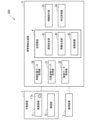
- FIG. 1 is a diagram showing an example of the configuration of a control system 100 according to the first embodiment.
- the control system 100 includes a mobile device 1, an observation device 2, and an obstacle detection device 3 (an example of a processing device).
- the control system 100 is a system in which the control unit 12 (to be described later) controls the controlled unit 11 having the movable unit 11a based on the information obtained from the observation device 2 in the movable unit 1 .
- the mobile device 1 includes a controlled portion 11 (an example of a controlled object) that is to be controlled, and a control portion 12 that controls the controlled portion 11 (an example of control means).
- the movable device 1 is, for example, a robot having an arm, a transport vehicle, a construction machine (hereinafter referred to as a construction machine), etc., but is not limited to these.
- construction machines having arms include power shovels, backhoes, cranes, and forklifts.
- the controlled section 11 is a housing portion such as an arm, a bucket, and a shovel that performs work.
- the controlled portion 11 has a movable portion 11a.
- the movable part 11a is, for example, an actuator.
- the control unit 12 controls the controlled unit 11 . As the control section 12 controls the controlled section 11, the movable section 11a of the controlled section 11 operates.
- the observation device 2 observes at least the space in which the mobile device 1 operates, and outputs observed observation information (an example of actual measurement values).
- the observation device 2 acquires the movable range of the controlled unit 11 as image (RGB) or three-dimensional image (RGB-D) data, for example, a monocular, compound eye, monochrome, RGB, depth camera, ToF (Time of Flight)
- RGB image
- RGB-D three-dimensional image
- it is a device that optically measures the distance to the target, such as a lidar (Light Detection And Ranging; LiDAR), or a device that measures with radio waves, such as a radar ( Radio Detection and Ranging (Radar), etc., and the specific configurations of these devices are not limited in this embodiment.
- the observation device 2 may be a single device such as these, or may be a combination of multiple devices.
- the observation device 2 also acquires observation data for an observation area including at least the movable range of the controlled section 11 . Therefore, the observation data includes at least part of the housing of the controlled unit 11 .
- the observation data includes information about the surrounding environment such as obstacles and information about the controlled section 11 of the mobile device 1 to be controlled.
- the observation area of the observation device 2 is determined by conditions such as the installation position and installation direction (angle) when the observation device 2 is installed, and the performance and parameters specific to the observation device.
- the installation of the observation device 2 is appropriately determined based on the type and performance of the observation device 2, the specifications (for example, type, size, movable range, etc.) of the movable device 1 to be observed, the work content, and the surrounding environment. and is not limited by the present invention.
- the types are different measurement methods, and examples of types include cameras, video cameras, lidars, and radars. Examples of performance include field of view (FOV), maximum measurable distance, and resolution.
- FOV field of view
- the observation device 2 may be mounted on the mobile device 1 .
- the obstacle detection device 3 includes a position and orientation data acquisition unit 31 that acquires position and orientation data of the controlled unit 11 , an observation data acquisition unit 32 that acquires data of the observation device 2 , and information obtained by the observation device 2 .
- An information exclusion unit 33 (an example of exclusion means) that excludes information about the controlled unit 11 and outputs information after the exclusion, information output from the information exclusion unit 33, and information described later in the virtual environment 4
- the determination processing unit 34 (an example of determination means, an example of processing means) that performs determination processing regarding detection of an obstacle for the control system 100 and at least the controlled unit 11 are calculated. It comprises a virtual environment 4 simulated above.
- the position and orientation data acquisition section 31 acquires the position and orientation data of the controlled section 11 .
- the mobile device 1 is an arm of a robot, that is, a so-called articulated robot arm
- angle data of each joint of the arm is acquired as the position/orientation data.
- This angle data can typically be acquired as an electrical signal by a sensor (for example, a rotary encoder) attached to an actuator that drives each joint.
- a sensor for example, a rotary encoder
- the position and orientation data is acquired by sensors attached to each movable portion 11a of the controlled portion 11 or the housing.
- sensors include an external sensor such as an inclination sensor, a gyro sensor, an acceleration sensor, an encoder, and a hydraulic sensor.
- the installation positions and the number of sensors can be appropriately designed for each operation of the mobile device 1 to be detected.
- the position/attitude data follows the temporal change of the movable portion 11 a of the controlled portion 11 . That is, the electrical signal information acquired by the position/orientation data acquisition unit 31 is information acquired corresponding to the operation of the controlled unit 11 within a certain range of error and delay time.
- the temporal frequency (sampling rate) and spatial resolution (accuracy) of the signal are not particularly limited, and can be appropriately determined according to the size and characteristics of the movable device 1, work content, and the like.
- the observation data acquisition unit 32 preferably acquires the observation data output by the observation device 2.
- the observation data acquisition unit 32 may acquire information as observation data from other means, such as a sensor mounted on the mobile device 1 .
- the virtual environment 4 is an environment that simulates at least the controlled unit 11 in terms of calculation.
- the virtual environment 4 refers to a so-called digital twin, which is an environment in which the dynamics of the controlled unit 11 and the surrounding real environment are reproduced by executing a simulation using a simulator, a mathematical model, or the like.
- the virtual environment 4 is not restricted to digital twins.
- the first point is the shape of the controlled portion 11 .
- the virtual environment 4 has a model that reproduces the external shape, that is, the size and three-dimensional shape of the controlled part 11 within the same or a certain range of error or scale as the real controlled part 11 .
- the model of the controlled part 11 is based on, for example, the blueprint or CAD data of the controlled part 11, the image data of the controlled part 11, or the like, by polygons, or by a set of polygons (that is, a mesh). can be built.
- the model of the controlled unit 11 is represented by polygons
- approximation is performed according to the shape, size, density, and the like of the polygons.
- the degree of approximation can be appropriately determined depending on the size of the controlled section 11 to be controlled.
- the model of the controlled portion 11 is represented by polygons, the model represents a three-dimensional shape, so it is not necessary to reproduce the material, texture, pattern, etc. of the surface.
- the method of constructing the model of the controlled unit 11 is not limited to the method described above.
- the second point is the movement of the controlled portion 11, that is, the movement (dynamics) of each movable portion 11a.
- the controlled part 11 includes a movable part 11a (actuator) controlled by at least one or more control parts 12, and the controlled part 11 in the virtual environment 4 described in the first point of the viewpoint of simulating the controlled part 11.
- the movable portion 11a is the same as the real controlled portion 11 or is reproduced within a certain range of error. It should be noted that reproduction of movement means that the same position and angle as the movable part 11a of the real thing can be displaced.
- the configuration method of the portion 11a is not limited.
- the virtual environment 4 may include virtual observation means corresponding to the real observation device 2 and an observation area to be observed. Virtual observation means will be described later.
- a controlled device 43 (an example of a model of the controlled section 11) that simulates the real controlled section 11 in the real environment and the controlled device 43 are set (the information generating section 42 is set to the observation device 2).
- the observation means is further set to the same position and orientation as the observation device 2)
- Environment setting unit 41 and information about the simulated controlled unit 11 is output.
- an information generation unit 42 for generating the information In the virtual environment 4, the environment setting unit 41 arranges a model simulating the real controlled part 11 (including the movable part 11a) in the controlled device 43 (that is, sets the position and posture), The position and orientation of the virtual observation device 2 simulating the observation device 2 are set.
- This model of the controlled part 11 and the virtual observation device 2 are related to the relative positions and orientations of the real controlled part 11 and the real observation device 2 in the three-dimensional area handled in the virtual environment 4 . Arranged to be identical or to be reproduced within a certain margin of error or scale. That is, when either the model of the controlled unit 11 or the virtual observation device 2 is used as a reference for the position and orientation, the difference in distance and angle to the other is the same as the real thing, or within a certain error range or scale. It has become. It should be noted that the scale here corresponds to the scale of the model of the controlled section 11 described above.
- the virtual environment 4 handles an area including the movable range of the real controlled part 11
- the model simulating the real controlled part 11 and the virtual observation device 2 are positioned at the same position as the real controlled part 11 . and posture.
- Such setting of the relationship between the model of the controlled unit 11 and the position and orientation of the observation device 2 is generally called calibration. That is, the model of the controlled unit 11 and the virtual observation device 2 are set to a calibrated state. It should be noted that the setting of structures other than the model of the controlled unit 11 and the boundaries of the space such as the ground are not essential.
- the movable part 11 a of the model of the controlled part 11 is set based on the information about the real controlled part 11 acquired by the position/orientation data acquisition part 31 .
- the three-dimensional shape of the model of the controlled portion 11 is the same as that of the movable portion 11a of the actual controlled portion 11, or is set within a certain range of error, so that the three-dimensional shape of the model of the controlled portion 11 is similar to that of the actual object. It can be represented similarly to the shape of the controlled portion 11 .
- the temporal displacement of the movable portion 11 a of the real controlled portion 11 is set by the environment setting portion 41 based on the information acquired by the position/orientation data acquisition portion 31 . Therefore, the model of the controlled part 11 in the virtual environment 4 can be moved in the same manner as the real controlled part 11 within a certain range of error or delay time.
- the model of the controlled part 11 in the virtual environment 4 is synchronized (synchronized) with the real controlled part 11 .
- the information generating unit 42 generates at least information about the model in the virtual environment 4 in which the real controlled unit 11 is simulated.
- the model of the controlled portion 11 reproduces the shape and movement of the real controlled portion 11, the shape and movement of the controlled portion 11 can be obtained by executing a simulation using the model.
- Information corresponding to motion is generated.
- the generated information is a set of three-dimensional positions occupied by the three-dimensional shape of the model of the controlled unit 11 at a certain time in the three-dimensional space handled in the virtual environment 4, or Time-series values of three-dimensional positions according to the temporal displacement of the model of part 11 (for example, gray grids in part (b) of FIG. 7 to be described later).
- the generated information is a set of positional information of each polygon representing the three-dimensional shape of the model of the controlled section 11 .
- the spatial resolution of this positional information depends on the size of the polygon representing the model of the controlled unit 11 and the like.
- the resolution can be changed by, for example, interpolating (up-sampling) or thinning (down-sampling) the positional information of polygons.
- the resolution is changed by increasing the spatial resolution, that is, by expressing with fine polygons or performing upsampling. can be executed by lowering the resolution, that is, by down-sampling the polygon position information.
- virtual observation means corresponding to the observation device 2 can also be used.
- This observation means is similar to the real observation device 2 by installing the virtual observation device 2 in a virtual three-dimensional space corresponding to the position and orientation of the real observation device 2 set by the environment setting unit 41 .
- Observation data that is, images and three-dimensional images can be obtained virtually.
- the observation means has a function of simulating the observation device 2 and simulating and outputting observation information observed from the installed position and orientation of the observation device 2 .
- the observation range of the observation device 2 includes at least the movable range of the controlled section 11, and the observation information output by this observation means is information indicating the same range.
- the observation means outputs information (an example of an estimated value) obtained by observing a model simulating the controlled section 11 . That is, information on the shape indicated by the model of the controlled portion 11, information on the position of the model of the controlled portion 11 in the three-dimensional space, and time-series information corresponding to the movement indicated by the model of the controlled portion 11 are obtained.
- This virtual observation means is preferably an observation device having the same performance as the observation device 2, ie, an imaging range and resolution. It should be noted that the virtual observation means may be appropriately adjusted according to the processing power of the computer that processes the information generating section 42 and the like. Further, the information generating section 42 may generate information other than the part corresponding to the model of the controlled section 11 .
- the information generating unit 42 generates information on structures other than the model of the controlled unit 11 reproduced in the virtual environment 4, information on the boundary of space such as the ground, or information dependent on the work performed by the mobile device 1. may be generated.
- the movable device 1 is a robot arm or a construction machine
- the information depending on the work is the target object, the work area, and the like on which the controlled section 11 works.
- the information exclusion unit 33 performs processing to exclude information from the information acquired by the observation data acquisition unit 32 based on the information generated by the information generation unit 42 of the virtual environment 4. Specifically, the three-dimensional shape generated by the information generating unit 42 of the virtual environment 4 is excluded from the information obtained by the observation data obtaining unit 32, that is, the observation information corresponding to the observation data output by the observation device 2. Do (filtering, masking) processing. As described above, the observation information includes at least part of the controlled portion 11, and the information generated by the information generating portion 42 includes at least the shape information of the model in which the controlled portion 11 is simulated. .
- the information exclusion unit 33 can output information in which the controlled unit 11 is excluded from the observation information, in other words, observation information that does not include the controlled unit 11 by the exclusion processing of these two pieces of information.
- Observation information that does not include the controlled part 11 is, for example, other structures. is defined as information (obstacle candidate information) that includes an area that becomes an obstacle to
- region is an area
- the obstacle candidate information does not include areas that permit approaching or entering.
- the obstacle candidate information output by the information exclusion unit 33 based on the time-series data of the observation data acquisition unit 32 and the information generation unit 42 corresponding to the movement of the controlled unit 11 is also It becomes time series data. That is, in synchronization with the movement of the controlled portion 11, the area corresponding to the controlled portion 11 is excluded.
- Methods for excluding the region corresponding to the controlled portion 11 include a method of comparing the three-dimensional information of each of the observation data acquisition portion 32 and the information generation portion 42, and a method of comparing three-dimensional information of each of the observation data acquisition portion 32 and the information generation portion 42.
- Information can also be represented by regular grids (voxels) occupied in a three-dimensional space, and a process of detecting overlap between the grids, such as logical operations such as XOR (Exclusive OR), can also be used.
- a process of detecting overlap between the grids such as logical operations such as XOR (Exclusive OR)
- the method of excluding the area corresponding to the controlled portion 11 is not limited to these methods.
- the information exclusion portion 33 can perform processing for excluding an area corresponding to the controlled portion 11 with a sufficiently small delay, and the obstacle candidate information includes the controlled portion The region corresponding to 11 is not included.
- the information exclusion unit 33 cannot properly exclude the area corresponding to the controlled unit 11, and the obstacle candidate information includes a part of the area corresponding to the controlled unit 11.
- the information excluding section 33 may exclude an area slightly larger than the three-dimensional information output by the information generating section 42, for example. It can be adjusted so that the region is not included.
- This adjustment may be performed by multiplying the three-dimensional area output by the information generation unit 42 by a coefficient exceeding 1.
- This coefficient is used as a parameter such as the operating speed of the controlled unit 11 and the processing capacity of the information exclusion unit 33. can be adjusted as appropriate. Note that the above adjustment is only an example and is not limited to this.
- the determination processing unit 34 receives the obstacle candidate information output from the information exclusion unit 33 and the information output from the information generation unit 42 in the virtual environment 4, and determines the obstacle detection. Perform judgment processing.
- the obstacle candidate information output by the information exclusion unit 33 is information including an area that the controlled unit 11 should not approach or enter, that is, an obstacle area.
- the shape information output from the information generation unit 42 is information within the virtual environment 4 corresponding to the shape and movement of the controlled unit 11 .
- the obstacle candidate information output by the information exclusion unit 33 is based on observation information obtained by the observation device 2 in the real environment.
- the shape information output from the information generation unit 42 is information in the virtual environment.
- the determination processing unit 34 compares the obstacle candidate information output by the information excluding unit 33 with the information dynamically representing the controlled unit 11, which is the shape information output from the information generating unit 42, to It can be determined whether the control unit 11 is approaching or entering (in contact with) an area of an obstacle. For this determination, for example, the distance between the three-dimensional position indicated by the obstacle candidate information and the set of positions indicated by the three-dimensional position set information output by the information generation unit 42 is calculated, and a set threshold value is calculated. It can be realized by evaluating whether or not the limit is exceeded.
- Collective information which is a collection of three-dimensional position information, can be expressed as a set of points representing three-dimensional coordinates, for example, point cloud data, and the distance between each set can be expressed as, for example, It can be calculated as the Euclidean distance between centroids, the Euclidean distance of the closest points (nearest neighbor points), and the like.
- a method of finding the nearest neighbor point is, for example, a method of using an algorithm such as nearest neighbor search or k-nearest neighbor search.
- the method of finding the nearest point is not limited to methods using nearest neighbor search or k-nearest neighbor search algorithms. Also, this determination can be realized by the processing opposite to that of the information exclusion unit 33 described above.
- each set information of the obstacle candidate information and the three-dimensional position output by the information generation unit 42 is represented by a three-dimensional regular grid (voxel), and the grid Matching grids between or between surrounding grids mean that there are locations in three dimensions that are close together. Therefore, in the determination, for example, a process (for example, XOR operation) is performed to see the overlap between the grids with a certain predetermined resolution. It indicates that the area of the obstacle is not approached, and if overlap is detected, it indicates that the controlled section 11 is approaching the area of the obstacle.
- a process for example, XOR operation
- the resolution of this overlap detection that is, the size of the lattice (voxel) depends on the point cloud density (that is, the size of the mesh) of each three-dimensional information, and also depends on the processing capability of the determination processing unit 34. It can be set as appropriate. Preferably, by setting a wide grid size, the approach is determined early, that is, when the distance between the obstacle region and the controlled section 11 approaches the set grid size. On the other hand, by setting a narrow grid size, the spatial resolution for determining the distance between the obstacle region and the controlled part 11, that is, the spatial accuracy is improved. Even if it is, it is possible to determine with high accuracy. Note that these determination methods are examples, and any method may be used as long as it can determine whether or not the controlled portion 11 is close to an obstacle area.
- the result of the determination by the determination processing unit 34 may be announced on a display or the like (not shown).
- the control command output by the control unit 12 of the mobile device 1 to the controlled unit 11 may be changed based on the determination result. For example, by changing the control command output to the controlled unit 11, the control unit 12 may limit the operating range of the controlled unit 11, limit the operating speed of the controlled unit 11, or limit the operating speed of the controlled unit 11. 11 may be stopped. Any method may be used to change these control commands.
- the resolution in space is the threshold for determining the distance between a set of points representing three-dimensional coordinates indicated by three-dimensional information, or the resolution when expressed in voxels (lattice size, that is, the mesh size). magnitude), but this value need not be set to a single value.
- a plurality of different values may be set as thresholds and grid sizes.
- the determination processing unit 34 can make determinations in parallel. As described above, the time to determination and spatial accuracy are traded off depending on the spatial resolution setting.
- a large value and a small value are set as the distance threshold value, and in the case of a large value, the judgment processing unit 34 judges quickly when the distance is long, so an instruction to decelerate the controlled unit 11 is issued.
- the determination processing unit 34 makes a highly accurate determination when the distance becomes close, and therefore, when an instruction to stop the controlled unit 11 is issued, it is possible to determine whether to decelerate or stop.
- the determination processing unit 34 performs determinations using a wide grid size (coarse resolution) and a narrow grid size (fine resolution) in parallel.
- An instruction to decelerate may be output when the size is determined, and an instruction to stop may be output when the determination processing unit 34 determines a narrow grid size.
- the judgment processing unit 34 makes a judgment using a large distance threshold value or a wide grid size, and after the controlled unit 11 is decelerated, the judgment processing unit 34 judges that it is not close to the obstacle area. In this case, the control by the control unit 12 may be returned to the original control.
- the control unit 12 can efficiently operate the movable device 1 without excessively stopping the controlled unit 11 .
- the above determinations by the determination processing unit 34 are examples, and the present invention is not limited to these.
- the determination processing unit 34 may set multi-step (multi-value) resolution and perform multi-step determination.
- FIG. 2 is a flowchart showing an example of the procedure of processing performed by the control system 100 according to the first embodiment. Next, the processing of the control system 100 will be described with reference to FIG.
- the position/posture data acquisition unit 31 of the obstacle detection device 3 acquires position/posture data from the mobile device 1, and the observation data acquisition unit 32 acquires observation data from the observation device 2 (step S101).
- the environment setting unit 41 of the obstacle detection device 3 sets the virtual environment in the virtual environment 4 based on the configuration of the real environment and the acquired position and orientation data (step S102). Specifically, the environment setting unit 41 sets the relationship between the position and orientation of the model of the controlled unit 11 simulated in the virtual environment and the real observation device 2, that is, calibration processing, Perform processing to reflect the acquired position and orientation data in the model.
- the information generation unit 42 outputs shape information based on the state of the controlled unit 11 in the real environment for the simulated model (step S103). Specifically, the information generating unit 42 generates, for example, a set of three-dimensional positions occupied by the three-dimensional shape of the model in the virtual environment 4 synchronized with the controlled unit 11 in the real environment, or It outputs time-series values of three-dimensional positions according to the temporal displacement of the model in the virtual environment 4 synchronized with the unit 11 .
- the information exclusion unit 33 excludes regions that are not determined as obstacles from the observation data of the real environment, and outputs the excluded obstacle candidate information (step S104).
- the area not determined as an obstacle is, for example, an area corresponding to the controlled unit 11 or an area scheduled to be approached or entered during work by the movable device 1, and the user registers an area that is not determined as an obstacle.
- the information exclusion unit 33 may register it as information in advance.
- the determination processing unit 34 determines from the obstacle candidate information and the shape information the distance between the two pieces of information (that is, the distance between the obstacle area and the controlled unit 11).
- a related value preferably proportional to the distance
- the specified determination value is output (step S105). Examples of the determination value include a value proportional to the distance between the obstacle area and the controlled section 11, and "overlap" corresponding to the distance between the obstacle area and the controlled section 11 (for example, FIG. 8 part indicated by a dot-patterned lattice where the obstacle area and the controlled part overlap when the distance to the obstacle is less than the threshold value).
- the determination value indicates the distance between the three-dimensional area representing the obstacle candidate information and the three-dimensional area representing the dynamic shape of the controlled section 11 .
- a threshold value is appropriately set according to the type of determination value output by the determination processing unit 34 .
- the determination processing unit 34 determines whether or not the determination value is equal to or greater than the threshold (step S106). If the determination value is equal to or greater than the threshold value (YES in step S106), the determination processing unit 34 determines that the distance between the controlled unit 11 and the obstacle area is long, and therefore determines that the mobile device 1 continues to operate. , the flow returns to the start (the process starting from step S101 is repeated thereafter).
- step S106 NO determines that the determination value is less than the threshold value (step S106 NO)
- the determination processing unit 34 determines that the controlled unit 11 is approaching or entering the obstacle area, and indicates that an obstacle has been detected.
- An alert is output (step S107).
- the determination processing unit 34 then outputs an instruction to the control unit 12 of the mobile device 1 .
- the instruction to the control unit 12 by the determination processing unit 34 is an instruction to restrict the operation range of the controlled unit 11, limit the operation speed, or stop the operation. It may be set so as to provide different instructions.
- step S107 After the process when an obstacle is detected (the process of step S107), the flow basically returns to the start (the process starting from step S101 is repeated). However, if the operation returns to the start even once, or if the controlled unit 11 is stopped by an instruction to the control unit 12, recovery work for moving the controlled unit 11 away from the failure area is performed as appropriate.
- the controlled section 11 of the mobile device 1 can be operated safely without approaching or entering the area of the obstacle observed by the observation device 2 .
- the instructions to the control unit 12 described in the processing when an obstacle is detected step S107
- a decrease in work efficiency due to the stop is prevented, You can work safely and efficiently.
- control system 100 (advantage) The control system 100 according to the first embodiment has been described above. Advantages of control system 100 over control systems to be compared will now be described.
- the first method is to preset an area to be determined as an obstacle based on the observation results and the movable range of the movable device 1 . Since this method is set in advance, errors in judgment and oversight are less likely to occur. However, since it is necessary to set the area in advance, it is difficult to set the area according to the minimum required area or the dynamically changing area for changing environments and obstacles. Therefore, in this method, an area that is wider than necessary (that is, with a margin) is set in advance, and the determination processing unit 34 may make excessive determinations.
- the second is a method of detecting an obstacle and estimating its position based on observation information.
- object detection methods using deep learning can be applied, but there are cases where it is necessary to learn the object detection target in advance, and there are cases where there is no guarantee that unknown obstacles can be reliably detected. . In other words, erroneous detection or oversight (missed detection) may occur.
- erroneous detection or oversight missed detection
- the control system 100 according to the first embodiment does not perform processing for preliminarily setting areas and objects related to obstacles, and preliminarily detecting obstacles and objects. All areas excluding areas and objects determined to be non-existent, that is, areas into which entry is permitted depending on the controlled unit 11 and work are set as obstacle candidate information. That is, in the control system 100, an oversight that an obstacle is not detected does not occur. Then, the control system 100 compares the obstacle candidate information with the virtual environment information in which the actual shape and motion of the controlled unit 11 are simulated.
- the obstacle candidate information and the information of the controlled part 11 are generated as different information and compared, so that the area of the controlled part 11 can be extracted from the observed information, or the same observation information can be obtained. , the process of estimating the distance between the obstacle and the controlled unit 11 does not occur. That is, in the control system 100, no processing errors or estimation errors occur. Furthermore, in the control system 100, even if part of the observation information about the controlled part 11 is lost, that is, even if part of the controlled part 11 is shielded, the information generated in the virtual environment is controlled. Since it is based on the shape model of the part 11, the control system 100 is not affected by information loss or shielding, and has high robustness. In this way, the control system 100 is characterized by not using an object detection technique and making decisions based on observed information and information based on a model of the virtual environment. It is possible to precisely control the controlled unit 11 with good work efficiency while detecting obstacles with high accuracy and certainty.
- FIG. 3 is a diagram showing an example of the configuration of a control system 200 according to the second embodiment.
- the obstacle detection device 3 further includes an information comparison section 35 in addition to the configuration of the control system 100 according to the first embodiment shown in FIG. Since other configurations are the same as those of the control system 100 according to the first embodiment, description thereof will be omitted below.
- the information comparison unit 35 stores the observation information obtained by the observation data acquisition unit 32, in which the controlled unit 11 is included in the observation range, and the controlled object generated by the information generation unit 42 of the virtual environment 4. Shape information about a model simulating the part 11 is input.
- three-dimensional information reflecting the shape of the controlled part 11 included in the observation information and the shape of the model synchronized with the controlled part 11 generated by the information generating unit 42 of the virtual environment 4 are reflected.
- Three-dimensional information agrees within a certain margin of error.
- the first point is based on the definition of the model that simulates the controlled unit 11 in the virtual environment 4 . Since this model simulates the shape of the real controlled part 11, the three-dimensional information based on the shape, that is, the three-dimensional information of the portion occupied by the controlled part 11 represented by the model in the virtual space is , is equal to three-dimensional information obtained by observing the controlled portion 11 with the observation device 2 in the real space.
- the second point is that the coordinate system of the observation device 2 in the real space and the coordinate system for generating the shape information indicated by the model match.
- the environment setting unit 41 makes the relationship between the positions and orientations of the controlled unit 11 and the observation device 2 match the relationship between the model in the virtual environment 4 and the reference point when generating the shape information included in the model. This is because it is set (calibrated) as
- the third point is that the dynamic displacement of the controlled unit 11 is acquired via the position/orientation data acquisition unit 31 and reflected in the model in the virtual environment 4 by the environment setting unit 41 . That is, it can be considered that the operations of the controlled section 11 and the model are synchronized within a certain specified delay time range. Therefore, even when the controlled section 11 moves, both pieces of three-dimensional information input to the information comparing section 35 match within a prescribed delay time range.
- the operating state is not ideal. Specifically, the situation is as follows. First, in response to the first reason, there is a mismatch in shape between the actual controlled unit 11 and the model in the virtual environment 4 . This state can occur, for example, when a mobile device different from the assumed mobile device 1 is connected, or when there is an error in the processing of the environment setting section 41 of the virtual environment 4 . Next, there is a deviation in the coordinate system corresponding to the second reason.
- This state can occur when calibration is inappropriate, or when the position and orientation of the observation device 2 change after calibration.
- the position and orientation data of the controlled unit 11 cannot be properly acquired.
- a malfunction of a sensor that acquires the position and orientation of the controlled unit 11 a malfunction of the route connecting the movable device 1 and the obstacle detection device 3, a malfunction of the processing in the position and orientation data acquisition unit 31, and the like occur. can occur if
- Determination of these defects can be realized by evaluating the distance between information input to the information comparing unit 35, that is, the distance between set information of points representing three-dimensional coordinates indicated by the three-dimensional information.
- a method for calculating the distance for example, a method equivalent to the processing in the determination processing unit 34 described in the first embodiment can be applied. Specifically, if the distance between the two pieces of input information is less than a threshold value, the information comparison unit 35 determines that the two pieces of information match, that is, that there is no problem. On the other hand, if the distance is equal to or greater than the threshold, the information comparing section 35 determines that the two pieces of information do not match, that is, that there is a problem.
- the determination processing unit 34 When determining that there is a problem, the determination processing unit 34 sends an alert or an instruction to the control unit 12 in the same manner as when an obstacle is detected.
- the threshold for determination can be appropriately set according to the size, operating speed, amount of information (possible), and the like of the controlled unit 11 .
- FIG. 4 is a flowchart showing an example of the procedure of processing performed by the control system 200 according to the second embodiment. Processing of the control system 200 will be described with reference to FIG. Among the processes shown in FIG. 4, the same step numbers are assigned to the same processes as those of the control system 100 according to the first embodiment, and descriptions thereof are omitted.
- the information comparison unit 35 collects the observation data of the real environment acquired by the observation data acquisition unit 32 and the virtual environment input the shape information generated by the information generation unit 42 for the model, and output a comparison value related to the distance between both pieces of information (that is, the distance between the obstacle area and the controlled unit 11) (Step S201).
- this comparison value is compared with a threshold value, and if it is less than the threshold value (step S202 YES), the information comparison unit 35 determines that there is no problem with the control system 200, and thereafter the first embodiment is performed.
- a similar flow (steps S104 to S106) is operated.
- the information comparison unit 35 determines that there is a problem with the control system 200, and outputs an alert for detecting a problem or an obstacle (step S203).
- This flow is similar to the control system 100 according to the first embodiment when an obstacle is detected (step S106 NO), but in the control system 200 according to the second embodiment, An alert is output even if there is a problem.
- failure and obstacle detection are determined differently (steps S201 and S106), they may be output as identifiable alerts.
- an instruction may be output to the control unit 12 in addition to the alert.
- control system 200 has been described above.
- control system 200 according to the second embodiment in addition to the control system 100 according to the first embodiment, by further including an information comparison unit 35, correspondence between the movable device 1 and the virtual environment 4 as described above , the position and orientation of the observation device 2 , and calibration, and the signal path connecting the movable device 1 and the sensor that acquires the position and orientation information of the controlled unit 11 . That is, before determining whether or not the controlled unit 11 is approaching or entering an obstacle area, whether the movable device 1, the observation device 2, and the obstacle detection device 3 are in a state in which the determination can be performed normally. It is possible to detect whether or not there is a problem with the control system 200 . This makes it possible to detect obstacles separately from other system failures. Therefore, the control system 200 can more reliably detect obstacles by taking recovery measures when a malfunction state is detected.
- FIG. 5 is a diagram showing an example of the configuration of a control system 300 according to the third embodiment.
- the obstacle detection device 3 further includes a control plan data acquisition unit 36 in addition to the control system 100 according to the first embodiment. Since other configurations are the same as those of the control system 100 according to the first embodiment, description thereof will be omitted below.
- a configuration combined with the second embodiment, that is, a configuration further including an information comparison unit 35 is also possible.
- the control plan data acquisition unit 36 acquires control plan information for controlling the controlled unit 11 of the movable device 1 .
- the control plan data acquisition section 36 acquires the control signal generated by the control section 12 .
- any generation method and acquisition route can be used. It may be a route.
- the information of the control plan is, for example, information of a target position when a specific part of the controlled part 11 moves from the current position to the target position, or information of the movable part 11a (actuator) constituting the controlled part 11 at that time.
- the control plan data acquisition unit 36 acquires the position/orientation information for which future control is planned (scheduled). get.
- the frequency of acquiring this future control plan information may be acquired for each specific operation or time when the target position changes, or periodically. That is, the information on the future control plan is time-series information, like the current position and orientation information acquired by the position and orientation data acquisition unit 31 .
- the future control plan information acquired by the control plan data acquisition unit 36 is input to the environment setting unit 41 of the virtual environment 4 .
- the environment setting unit 41 sets the position and orientation of the model simulating the controlled unit 11 based on the current position and orientation information acquired by the position and orientation data acquisition unit 31. do.
- the model is in a state synchronized with the current state of the real controlled unit 11 .
- the third embodiment does not change this point, but differs from the first and second embodiments in that it has a model that simulates another controlled unit 11 .
- the position and posture of this model are set based on the control plan information acquired by the control plan data acquisition unit 36 . That is, the model will be in sync with the states given in the control plan.
- the third embodiment is characterized in that different states of the controlled unit 11, that is, the current state and the state based on the control plan, are reproduced in the virtual environment 4.
- FIG. an example of the present and one type of control plan, that is, two states is shown, but the number of states to be reproduced is not limited to this. That is, a plurality of different states may be reproduced based on control plan information at a plurality of different timings.
- the information generation unit 42 in the virtual environment 4 of the third embodiment processes the multiple different state models described above. That is, the information generation unit 42 generates position information occupied by the three-dimensional shape of the model corresponding to the current position and orientation of the controlled unit 11, and the position and orientation of the controlled unit 11 planned based on the control plan. Position information occupied by the three-dimensional shape of the model is generated. Note that the same method as in the first embodiment can be applied to this generation by the information generation unit 42, and the number of pieces of information to be generated corresponds to the number of different models. That is, as described above, when a plurality of different models are reproduced based on a plurality of different control plans, the information generator 42 generates information matching the number of different models.
- the inputs and outputs of the observation device 2, the observation data acquisition unit 32, and the information exclusion unit 33 are the same as in the first embodiment, so descriptions thereof will be omitted.
- the processing performed by the control system 300 according to the third embodiment is basically the same as the flowchart of the control system 100 according to the first embodiment shown in FIG. Moreover, as described above, the control system 300 according to the third embodiment can also be applied to the control system 200 according to the second embodiment. Therefore, the processing performed by the control system 300 according to the third embodiment can be the same processing as the flowchart of the control system 200 according to the second embodiment shown in FIG.
- the control system 300 according to the third embodiment has been described above. Similar to the determination processing unit 34 of the first embodiment, the determination processing unit 34 of the third embodiment includes obstacle candidate information output by the information exclusion unit 33 and a plurality of models output by the information generation unit 42. 3D shape information based on is input. A method of performing determination processing based on these pieces of information will be described.
- the control system 300 of the third embodiment is similar to the control system 300 of the first embodiment in that the obstacle candidate information and the shape information output by the information generation unit 42 output a judgment value related to the distance between the two pieces of information. is similar to the control system 100 by, and similar methods are applicable.
- the control system 300 processes each piece of shape information. That is, the control plan data acquisition unit 36 in the control system 300 performs determination processing by inputting obstacle candidate information and shape information generated from a model corresponding to the current state of the controlled unit 11, and obstacle candidate information and a process of inputting and determining shape information generated from a model corresponding to the state of the controlled part 11 based on the control plan. Preferably, even when there is a plurality of pieces of shape information, the control plan data acquisition unit 36 can perform the above processes in parallel.
- the control plan data acquisition unit 36 can output determinations for each piece of shape information, and can instruct the control unit 12 to take different actions, that is, to instruct the movable device 1 .
- the control plan data acquisition unit 36 outputs an instruction to decelerate the controlled unit 11 based on the determination result based on the control plan, and an instruction to stop the controlled unit 11 based on the determination result based on the current state of the controlled unit 11. can be output.
- the control plan data acquisition unit 36 determines not only the current state but also the future planned state, so that the control system 300 can take early action before it actually starts moving. It is possible.
- the control unit 12 may control may not be in time.
- the control system 300 by applying the control system 300 according to the third embodiment, even if the movable device 1 with a high operating speed or a large delay, the obstacle is determined and the control unit 12 detects the obstacle. It becomes possible to control the control unit 11 .
- a first application example is an example in which the mobile device 1 in the first or second embodiment is a robot having an arm, a so-called articulated robot arm.
- FIG. 6 is a diagram showing an example of the configuration of the control system 400 of the first application.
- the mobile device 1 has a robot arm 11
- the observation device 2 is a device capable of acquiring three-dimensional information such as a depth camera or LiDAR
- the obstacle detection device 3 is the first to third It shows the configuration of a control system 400 in the case of any one obstacle detection device 3 in the embodiment.
- the mobile device 1 and the observation device 2 are each connected to the same obstacle detection device 3, but the number and configuration of the mobile device 1 and the observation device 2 to be connected are different from this. Not as long.
- a plurality of movable devices 1 and one observation device 2 may be connected to the obstacle detection device 3 .
- the mobile device 1 includes at least a controlled unit 11 and a control unit 12, like the mobile device 1 of the first or second embodiment.
- the robot arm 11 is the controlled unit 11 and the controller 12 is the control unit 12 that controls the robot arm 11 .
- the controlled unit 11 may be mounted on a moving device such as a movable unmanned (autonomous) guided vehicle (AGV: Automatic Guided Vehicle), and the configuration related to the hardware of the movable device 1 is the first application example It is not limited to the configuration described.
- AGV Automatic Guided Vehicle
- the robot arm 11 includes a movable portion 11a, which may approach or enter surrounding obstacles or obstructed areas.
- the control unit 12 may be included in the mobile device 1 or may exist in another location connected by a network, and the configuration of the control unit 12 and the generation of control signals may be controlled as desired.
- the configuration and control signal of the control unit 12 may be of any type as long as they can generate desired control signals.
- the observation device 2 is a device capable of acquiring three-dimensional information, such as a depth camera or LiDAR, like the observation device 2 of the first or second embodiment.
- the position where the observation device 2 is installed is not particularly limited, but at least a part of the housing of the robot arm 11 is included.
- FIG. 6 shows an example of an observation area 50 observed (captured) by the observation device 2 .
- the observation device 2 may be mounted on the robot arm 11, and when the robot arm 11 is mounted on a mobile device such as an autonomous carrier, the observation device 2 may be mounted on the mobile device. It's okay to be there.
- FIG. 6 shows an example of an observation area 50 observed by the observation device 2 .
- the observation area 50 includes at least part of the robot arm 11 .
- the object grasped in this task is assumed to be the object 51, and the object 51 is assumed to be included in the observation area 50.
- FIG. 6 illustrates a case where there are two target objects 51, the present invention is not limited to this.
- the robot arm 11 in order to perform the task of gripping the target object 51 by the robot arm 11 , the robot arm 11 needs to approach the target object 51 and finally come into contact with the target object 51 .
- the robot arm 11 has an end effector such as a robot hand, and the robot arm 11 performs the gripping task by bringing the end effector and the object 51 into contact.
- the robot arm 11 contacts the object 51, but the object 51 is not an obstacle, i.e. it needs to be allowed to approach or touch. Therefore, the area that the robot arm 11 allows contact with is shown in FIG. 6 as a target area 52 .
- the first application example is an example of a task in which two objects 51 are grasped, so the target area 52 is defined as an area including the two objects 51, but the setting method of this target area 52 is not limited.
- the target area 52 may be set for each object according to the outer peripheral surface of the object, may be set to include a specified margin on the outer peripheral surface of the object, or may be set to include a plurality of objects.
- can be Also shown in FIG. 6 is an obstacle or obstructed area 53 that the robot arm 11 is not allowed to approach or enter.
- the obstruction area 53 may be, for example, a structure, another object that is not to be grasped, or an area that does not have a physical shape but is not allowed to enter. may be a fault area.
- the obstacle area 53 is defined as a range included in the observation area 50 . That is, when the faulty area continues beyond the observation area 50 , the range defined by the observational area 50 becomes the faulty area 53 .
- the position/orientation data acquisition unit 31 of the obstacle detection device 3 acquires information on each joint (movable unit 11 a ) that configures the robot arm 11
- the observation data acquisition unit 32 acquires three-dimensional information on the observation area 50 .
- the virtual environment 4 constructs a model that simulates the three-dimensional shape and movement of the robot arm 11 .
- the model is set by the environment setting unit 41 based on the information acquired by the position/orientation data acquisition unit 31, so that the real robot arm 11 and the model in the virtual environment 4 are in a synchronized state, that is, a certain regulation is established.
- the position and posture match within the error range of .
- the model is set by the environment setting unit 41 in the virtual environment 4, that is, calibrated.
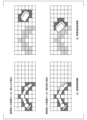
- FIG. 7 is a diagram for explaining a specific example of processing of the information comparison unit 35 according to the first application example.
- a specific example of processing of the information comparison unit 35 when using the obstacle detection device 3 of the second embodiment will be described with reference to FIG.
- the position in the three-dimensional space occupied by the robot arm 11 is shown as the real environment in part (a) of FIG. It is also, the position in the three-dimensional space occupied by the model generated by the information generation unit 42 in the virtual environment 4 is shown as the virtual environment in the part (b) of FIG.
- FIG. 7 indicates a state in which the comparison value output by the information comparison unit 35 is less than the threshold value, that is, the comparison value between the real environment and the virtual environment matches within a prescribed error range. show.
- the lower part of FIG. 7 shows a state in which the comparison value output by the information comparing section 35 is equal to or greater than the threshold value, that is, the control system 200 described in the second embodiment has a problem.
- the information that is actually input to the information comparison unit 35 is three-dimensional, it is shown as two-dimensional in FIG. 7 for convenience.
- the grid shown in FIG. 7 corresponds to the resolution of the coordinates when processed by the information comparing section 35, and is generally represented by a regular grid (voxel) in the case of three dimensions.
- a grid containing each three-dimensional coordinate is occupied by an object, which is represented in black in the grid shown in FIG.
- other grids that are not included in the input three-dimensional coordinates are represented in white in FIG. That is, as shown in FIG. 7, the grid occupied by the robot arm 11 is represented in black, and the other grids are represented in white.
- the state of each lattice can be represented by a binary value (binary variable: 0 or 1) indicating whether it is occupied (black: 1) or unoccupied (white: 0). can.
- the state of the k-th grid in the real environment shown in FIG. 7(a) is Creal,k
- the state of the k-th grid in the virtual environment shown in FIG. 7(b) is Csim.
- k the overlap ⁇ Ck of lattice k is given by
- the state of lattice k is the same in the real environment shown in part (a) of FIG. 7 and in the virtual environment shown in part (b) of FIG. , the overlap ⁇ Ck of lattice k is zero.
- the lattice k is occupied by either the real environment shown in part (a) of FIG. 7 or the virtual environment shown in part (b) of FIG. Become.
- the comparison value output by the information comparison unit 35 is, for example, a value obtained by adding the overlap ⁇ Ck of grid k represented by Equation (1) for all grid points. , that is, can be expressed as Equation (2).
- the number N of grid points is determined according to the volume of the target observation region 50 and the resolution (grid size) of the grid, and the computational complexity increases as N increases. increases.
- three-dimensional information can be expressed by an octree to enable high-speed calculation.
- the first application example is not limited to the calculation method using this octree.
- the overlap ⁇ Ck of grid k is 0, that is, the value of equation (2) is 0.
- the control system 400 can operate the processing (step S202) for determining the failure of the control system 200 shown in the flowchart of FIG.
- the example of the method of determining the malfunction mentioned above is an example, and is not limited to this method.
- the information exclusion unit 33 performs processing for excluding information from the information acquired by the observation data acquisition unit 32 based on the information generated by the information generation unit 42 . That is, the process is a process of removing the information of the portion corresponding to the robot arm 11 in the virtual environment shown in FIG. 7(b) from the information shown in the real environment shown in FIG. 7(a). Therefore, when there is no problem in the control system 400 (the comparison value is less than the threshold value in FIG.
- each piece of information is represented by a three-dimensional octree, and equally occupied lattices are replaced with information indicating that they are not occupied. There is a way.
- the reference position of each housing such as the center of gravity or center position, and the distance from there to the housing surface are calculated. be.
- the information exclusion unit 33 filters the portion of the robot arm 11 from the observation data.
- the method of excluding data by the information excluding unit 33 is not limited to these methods.
- the process of excluding data by the information excluding unit 33 is dynamically executed according to the motion of the robot arm 11 . In other words, even when the robot arm 11 moves, the data continues to be excluded. If there is a problem in the control system 400 (the comparison value is equal to or greater than the threshold value in FIG. 7), the real environment shown in part (a) of FIG.
- part corresponding to the robot arm 11 in the virtual environment shown in part (b) of (b) does not match. Therefore, even if the exclusion process is performed by the information exclusion unit 33, part of the portion corresponding to the robot arm 11 remains without being excluded. In other words, the portion of the robot arm 11 that has not been excluded is determined as an obstacle, and the processing of the determination processing unit 34 cannot be executed appropriately.
- the robot arm 11 executes the task of gripping the object 51, so the object 51 must be excluded from the determination as an obstacle. Therefore, the processing by the information exclusion unit 33 is performed on the area corresponding to the robot arm 11 and the target area 52 including the target object 51 .
- the area corresponding to the robot arm 11 is as described above.
- the environment setting unit 41 in the virtual environment 4 sets a three-dimensional area corresponding to the target area 52, that is, a model, and three-dimensional information about the area is set. is output by the information generator 42 .
- the position of the model corresponding to the target region 52 is determined based on the result of recognizing the position (and posture) of the target object 51 from the observation information about the target object 51 .
- the method of recognizing the position of the target object 51 is not limited in the first application example, but it may employ autonomous object recognition using point group processing or deep learning, or a position designated by a user or another device. It is also possible to recognize the position of the object 51 by using it. In this manner, the target area 52 is identified in the coordinate system of the observation device 2, similarly to the robot arm 11. FIG. Therefore, the target area 52 can be excluded from the information obtained by the observation data acquisition unit 32, similarly to the process of excluding the portion corresponding to the robot arm 11. FIG.
- the information excluding the robot arm 11 and the target area 52 becomes the obstacle candidate information of the first to third embodiments.
- the first application example only the area where the object is gripped has been considered, but in an actual task using the robot arm 11, an area where the gripped object is placed may be set. Including such cases, areas to be excluded can be arbitrarily added like the target area 52 of the first application based on the task or instructions of the user, and the number of areas to be excluded is not particularly limited.
- the addition of the area to be excluded and its exclusion method are the same as the addition of the area to be excluded of the target area 52 and its exclusion method.
- the above processing corresponds to the operation of step S104 in the flowchart shown in FIG. 2 or 4 of the first or second embodiment.
- FIG. 8 is a diagram for explaining the processing of the determination processing unit 34 according to the first application example.
- determination processing based on overlap between grids will be described.
- FIG. 8 shows controlled part information shown in part (a) of FIG. 3D information indicating the obstacle candidate information shown in the part (b) of FIG. Note that for convenience, FIG. 8 is shown two-dimensionally, like FIG. 7, and the state of each grid is represented in black if the grid is occupied, and unoccupied or has no information. are represented in white. Further, in the obstacle candidate information shown in part (b) of FIG.
- a cube is schematically represented as an example of an obstacle.
- a lattice corresponding to the robot arm 11, which is control unit information, is shown in an intermediate color between white and black (for example, gray).
- the information output from the information generation unit 42 and the obstacle candidate information output from the information exclusion unit 33 in the virtual environment 4 are represented by voxels.
- the state of the k-th lattice based on the controlled part information shown in part (a) of FIG. 8 is Crobot,k', and the obstacle candidate information shown in part (b) of FIG.
- the state of the th lattice is Cenv. , k′.
- the overlap of each lattice k is
- FIG. 8 shows an example of "when the distance to the obstacle is equal to or greater than the threshold".
- the controlled unit information shown in part a) and the obstacle candidate information shown in part (b) of FIG. That is, the value of overlap ⁇ Ck′ of grid k in equation (3) is 1 for grid k that is occupied. Therefore, the sum of the values of the overlap ⁇ Ck of the grid k with the number of grids occupied is equal to the number of grids occupied, as in Equation (2).
- the grids corresponding to the robot arm 11 (gray) and the grids corresponding to the obstacles (black) are in the same state, that is, the grids in which the grids overlap are indicated by diagonal lines.
- the value of the overlap ⁇ Ck' of the lattice k in the equation (3) is zero for the lattices having the same occupancy state (hatched lines). Therefore, when the sum of the values of the overlap ⁇ Ck' of the lattice k is calculated with the number of occupied lattices, the sum is smaller than the number of occupied lattices because the number of overlapping lattices is 0.
- the distance to the obstacle is greater than or less than the threshold value, that is, whether the robot arm 11 is approaching or entering the obstacle area. It is possible to determine whether or not there is
- the threshold for the distance to the obstacle depends on the resolution when expressed in voxels, that is, the grid size shown in FIG. The larger the grid size, the longer the threshold distance.
- the grid size can be appropriately determined according to the size and operating speed of the robot arm 11, the task to be executed, the processing capability of the determination processing unit 34, and the like. It should be noted that the method of calculating the overlap by expressing with voxels in this way has the advantage of high calculation efficiency because it is an expression using an octotree, as in the information comparison unit 35 described above.
- FIG. 9 is a diagram for explaining the processing of the determination processing unit 34 according to the first application example.
- FIG. 9 shows an example of determination processing performed by the determination processing unit 34 based on the nearest neighbor distance.
- the information output by the information generation unit 42 of the virtual environment 4 and the obstacle candidate information output by the information exclusion unit 33 are each expressed as a set of three-dimensional position information, for example, a set of points representing three-dimensional coordinates called point cloud data. can do.
- FIG. 9 shows three-dimensional information indicating the robot arm 11 as the information output by the information generating unit 42, and three-dimensional information indicating a cube as an example of the obstacle candidate information.
- the points with the closest Euclidean distance between the robot arm 11 and the obstacle are indicated by black dots, and the distances between the closest points are schematically indicated by arrows.
- the upper part of FIG. 9 shows "when the distance to the obstacle is greater than or equal to the threshold value", and as is clear from FIG. 9, the closest distance between the robot arm 11 and the cube is far.
- "When the distance to the obstacle is less than the threshold value” in the lower part of FIG. 9 indicates that the closest distance between the robot arm 11 and the cube is close.
- the threshold value can be appropriately determined according to the size and movement speed of the robot arm 11, the task to be executed, the processing capability of the determination processing unit 34, and the like.
- algorithms such as nearest neighbor search and k-nearest neighbor search can be used as a method of finding the nearest point.
- the above processing corresponds to the operation of step S105 in the flowchart shown in FIG. 2 or 4 of the first or second embodiment.
- the two types of specific processing methods of the determination processing unit 34 have been described above, the present invention is not limited to these.
- the mobile device 1 is a robot arm
- an instruction to limit the movement range or movement speed of the robot arm 11 or an instruction to stop the robot arm 11 is given, thereby improving work efficiency and safety.
- High and precise control of the controlled unit 11 can be realized.
- any mobile device 1 having a movable portion 11a such as other robots, machine tools, and assembly machines, can be applied.
- it can be suitably applied to a working machine in which the movable part 11a such as an arm may enter the obstruction area.
- the obstacle the case where there is one cube has been described as an example, but the shape and number of obstacles are not limited to this.
- a 2nd application example shows the example of a backhoe as a case where the movable apparatus 1 in 1st or 2nd embodiment is a construction machine.
- FIG. 10 is a diagram showing an example of the configuration of a control system 500 according to the second application.
- the mobile device 1 of the second application includes at least a backhoe 11, a control unit 12 that controls the backhoe 11, and an observation device 2 mounted on the backhoe 11, as shown in FIG.
- the observation device 2 is a device capable of acquiring three-dimensional information such as a depth camera or LiDAR.
- the obstacle detection device 3 is the same as the obstacle detection device 3 in the first to third embodiments.
- the configuration of the control system 500 shown in FIG. 10 is a configuration in which the movable device 1 and the obstacle detection device 3 are connected one-to-one, the number and configuration to be connected are not limited to this.
- the control system 500 may be configured to have a plurality of mobile devices 1 , that is, a plurality of backhoes 11 .
- the mobile device 1 includes at least the controlled unit 11 and the control unit 12, as in the first to third embodiments, and in the second application example, the backhoe 11 is the controlled unit 11 and controls the backhoe 11 Controller 12 is control unit 12 .
- the control unit 12 may be included in the mobile device 1 or may exist in another location connected by a network. not.
- the backhoe 11 may be automatically (autonomously) operated by the control unit 12, operated by an operator, or the operator may remotely transmit a control signal instead of the control unit 12. There are no restrictions on the method of controlling or manipulating 11.
- the operator may be warned by an alert or the like. may intervene in the operator's operation by sending a deceleration or stop signal to the
- FIG. 10 shows an example of an observation area 50 observed by the observation device 2 .
- the observation area 50 includes at least part of the backhoe 11 .
- a task assumed in the second application example is a task of excavating earth and sand present in a part of the target area 52 shown in FIG.
- FIG. 10 shows an obstacle or obstruction area 53 that the backhoe 11 is not allowed to approach or enter. This failure area 53 has the same meaning as the failure area 53 of the first application example.
- the position/orientation data acquisition unit 31 of the obstacle detection device 3 acquires information on each movable unit 11 a that constitutes the backhoe 11
- the observation data acquisition unit 32 acquires three-dimensional information on the observation area 50 .
- the position and orientation data may be obtained by a sensor attached to each movable portion 11a or the housing.
- the sensor may be, for example, an externally installed sensor such as an inclination sensor, a gyro sensor, an acceleration sensor, or an encoder.
- the virtual environment 4 constructs a model simulating the three-dimensional shape and movement of the backhoe 11 .
- the environment setting unit 41 sets the model based on the information acquired by the position and orientation data acquisition unit 31, so that the real backhoe 11 and the model in the virtual environment 4 are synchronized. The position and orientation can be matched within the error range of . Also, based on the relationship between the positions and orientations of the real backhoe 11 and observation device 2, a model is set by the environment setting unit 41 in the virtual environment 4, that is, calibrated.
- the position in the three-dimensional space occupied by the backhoe 11 and the position in the three-dimensional space occupied by the model generated by the information generation unit 42 are not They match within the margin of error.
- control system 500 can determine defects in the sensors attached to each movable unit 11a or the housing described above.
- the operation of control system 500 can be considered similar to control system 200 according to the second embodiment.
- FIG. 11 is a diagram for explaining the processing of the determination processing unit 34 according to the second application example.
- FIG. 11 schematically shows the processing of the determination processing section 34 when the obstacle detection device 3 of the third embodiment having the control plan data acquisition section 36 is applied.
- FIG. 11 shows two models of the virtual environment 4 simulating the real backhoe 11 .
- One is a model whose position and orientation are set based on the control plan acquired by the control plan data acquisition unit 36, and the other model reflects the current position and orientation acquired by the position and orientation data acquisition unit 31. model.
- FIG. 11 shows a cubic shape as an example of the obstacle region 53 .
- FIG. 11 shows the states of the respective models at two different times.
- the time shown on the left side of FIG. 11 is the first time
- the time after a certain period of time has passed from the first time shown on the right side of FIG. 11 is the second time.
- the state of the model is set based on both planning information and current information.
- the plan information is assumed to be the state after a certain period of time from the current state. That is, under ideal control, the current state will match the state based on the plan information after a certain period of time has passed.
- FIG. 11 shows, as an example of the processing of the determination processing unit 34, the determination method based on the nearest neighbor distance described in the first application example.
- arrows indicate the shape information of the model based on the plan information and the current information, and the nearest neighbor distance of the cube of the obstacle area 53 included in the obstacle candidate information. From FIG. 11, it can be seen that the model based on the planning information is close to the trouble area, but the model based on the current state is far from the trouble area.
- the determination based on the plan information it is determined that "the distance from the failure area is less than the threshold value (similar to the lower part of FIG. 9)", and in the determination based on the current information, "the distance from the failure area is too short”. Threshold value or more (upper part of FIG. 9)”.
- an instruction to decelerate the backhoe 11 is output by the determination based on the plan information, and the control of the backhoe 11 is continued without outputting the instruction by the determination based on the current state.
- the controller 12 that controls the real backhoe 11 can only receive one instruction, so it is necessary to select one of the instructions.
- This instruction selection can be realized by preparing a predetermined rule (algorithm) in advance. For example, since there is more time to make a decision based on plan information than a decision based on the current state, if the decision is made based on the plan information, the instruction should be "decelerate".
- the control system 500 updates the model based on the current position and orientation information, for example, without updating based on the planning information.
- the reason for this is that the plan information is up to a certain target value or is in a certain sequence, whereas the current information changes from moment to moment as long as the backhoe 11 is moving toward the target value.
- the position of the backhoe 11 indicated by the model based on the current information is closer to the position of the backhoe 11 indicated by the model based on the plan information than at the first time. That is, the position of the backhoe 11 indicated by the model based on the current information is also close to the obstacle. Therefore, at the second time, it is assumed that "the distance to the faulty area is less than the threshold". Then, at the second time, the approach of the backhoe 11 to the obstacle is detected in both the model based on the plan information and the model based on the current information.
- control plan data acquisition unit 36 selects to stop the backhoe 11 from the judgment result obtained by integrating the judgment result by the model based on the control plan and the judgment result by the model based on the current information. can be done.
- the integration of determination results described above is an example, and the integration of determination results by the control plan data acquisition unit 36 is not limited to stopping the backhoe 11 .
- FIG. 12 is a flowchart relating to processing of the determination processing unit 34 according to the second application example.
- the processing of steps S501 to S506 performed by the determination processing unit 34 based on the current position and orientation information is the same as the processing of steps S101 to S106 of the first embodiment shown in FIG.
- the determination processing unit 34 according to the second application acquires control plan information (step S507).
- the determination processing unit 34 sets the virtual environment based on the configuration of the real environment and the information on the control plan (step S508).
- the determination processing unit 34 outputs shape information based on the control plan for the model of the virtual environment (step S509).
- step S504 the process of step S504 is performed, and the determination processing unit 34 outputs a determination value related to the distance between the obstacle candidate information and the shape information of the control plan (step S510).
- the determination processing unit 34 determines whether or not the determination value is equal to or greater than the threshold (step S511).
- the determination processing unit 34 confirms whether the determination in the process of step S6 is YES or NO. Determination processing part 34 continues operation of mobile 1, when determination in processing of Step S6 is YES (Step S512). If the determination in step S6 is NO, the determination processing unit 34 integrates the determination results (step S513). As described above, the integration can be determined based on predefined rules such as, for example, alert only or instruction to slow down when based on plan information, or instruction to stop when based on current information. This rule can be appropriately determined in consideration of the work environment, the content of the task, the performance of the mobile device 1, and the like. Then, based on the integrated determination result, the determination processing unit 34 outputs an alert display and an instruction to the control unit 12 (step S514).
- predefined rules such as, for example, alert only or instruction to slow down when based on plan information, or instruction to stop when based on current information. This rule can be appropriately determined in consideration of the work environment, the content of the task, the performance of the mobile device 1, and the
- step S511 NO the determination processing unit 34 confirms whether the determination in the process of step S6 is YES or NO. If the determination in step S6 is YES, the determination processing unit 34 integrates the determination results (step S513). If the determination in the process of step S6 is NO, the determination processing unit 34 proceeds to the process of step S13.
- the second application example in which the movable device 1 is a construction machine and the controlled unit 11 is the backhoe 11 has been described above.
- the backhoe 11 approaches or enters an obstructed area, an instruction to limit the operating range or operating speed of the backhoe 11 or an instruction to stop the backhoe 11 is given, thereby improving work efficiency and safety. Precise control can be realized.
- the backhoe 11 was shown as an example of the to-be-controlled part 11 with which the mobile device 1 is equipped, it is applicable if it is the mobile device 1 which has the movable part 11a, such as another construction machine and a civil engineering construction machine.
- the technology described in the second application can be suitably applied to a working machine in which the movable portion 11a such as an arm may enter the obstruction area.
- the obstacles the case where there is one cubic obstacle has been described as an example, but the shape and number of the obstacles are not limited to this.
- FIG. 13 is a diagram for explaining the processing of the information generation unit 42 and the determination processing unit 34 according to the third application example.
- the information generation unit 42 according to the third application example generates information classified for each part of the robot arm 11 (arm 1, joint 1, arm 2, joint 2, arm 3, joint 3). That is, it outputs the occupation information of the three-dimensional space for each part.
- the "position information occupied by a plurality of three-dimensional shapes based on a plurality of control plans" in the third embodiment corresponds to the "occupancy information of the three-dimensional space for each part" in the third application example.
- the classification of the parts of the robot arm 11 described above is only an example and is not limited to this. A similar classification can also be applied to the second application example.
- the information generation unit 42 in the first application example outputs information as to whether or not the three-dimensional space is occupied by the robot arm 11 . That is, in the first application example, all the three-dimensional information indicating the robot arm 11 are of the same classification.
- the lower part of FIG. 13 shows a processing example of "when the distance to the obstacle is less than the threshold value" described in FIG. 8 in the first application example.
- the grid in which the obstacle region and the controlled section 11 overlap is the same grid (dot pattern) as in FIG. 8 in the first application example.
- the determination processing unit 34 is described as outputting information as to whether or not there is an overlap.
- the determination processing unit 34 provides status information indicating whether or not there is an overlap for each of the classified parts of the robot arm 11 (overlapping status information), as shown on the right side of the lower part of FIG. : detected, no overlap :-) is output.
- the obstacle candidate information is the same as the obstacle candidate information in the first application example, and the information generation unit 42 outputs a plurality of pieces of shape information for each part. Therefore, the process of outputting the status information by the determination processing unit 34 is the process of outputting a determination value related to the distance between the obstacle candidate information and the shape information (step S105) in the operation flow shown in FIG. ) and the process of determining whether the determination value is equal to or greater than the threshold value (step S106) can be realized by repeating the number of parts or executing them in parallel for each part.
- the present invention has been described with the above-described embodiments and application examples as examples. However, the invention is not limited to what has been described above.
- the present invention can be applied to various forms without departing from the gist of the present invention.
- some or all of the functions of the movable device 1, the observation device 2, and the obstacle detection device 3 may be provided in a device different from the own device.
- the device including the determination processing unit 34 is the processing device.
- FIG. 14 is a diagram showing the minimum configuration of the processing device 1000 according to the embodiment.
- the processing device 1000 includes a determination unit 1000a (an example of determination means) and a processing unit 1000b (an example of processing means).
- the determination unit 1000a determines whether or not the controlled object has entered a region other than the region where the controlled object is allowed to enter, in an environment that includes at least a part of the controlled object having a movable part.
- the processing unit 1000b executes a predetermined process when the determination unit determines that the controlled object has entered an area other than the area into which the controlled object is allowed to enter. Examples of the predetermined processing include notification that the controlled object has entered an area other than the area where entry of the controlled object is permitted.
- the determination unit 1000a determines whether or not the controlled object has entered a region other than the region where the controlled object is allowed to enter, in an environment that includes at least a part of the controlled object having a movable part (step S1001).
- the processing unit 1000b executes a predetermined process when the determining unit determines that the controlled object has entered an area other than the area into which the controlled object is allowed to enter (step S1002).
- the processing apparatus 1000 with the minimum configuration according to the embodiment of the present invention has been described above. With this processing device 1000, precise control of the controlled object can be realized.
- control systems 100, 200, 300, 400, 500, the movable device 1, the observation device 2, the obstacle detection device 3, and other control devices have computer systems therein. You may have The process of the above-described processing is stored in a computer-readable recording medium in the form of a program, and the above-described processing is performed by reading and executing this program by a computer. Specific examples of computers are shown below.
- FIG. 16 is a schematic block diagram showing the configuration of a computer according to at least one embodiment.
- the computer 5 includes a CPU 6, a main memory 7, a storage 8, and an interface 9, as shown in FIG.
- each of the control systems 100 , 200 , 300 , 400 , 500 , the mobile device 1 , the observation device 2 , the obstacle detection device 3 , and other control devices described above is implemented in the computer 5 .
- the operation of each processing unit described above is stored in the storage 8 in the form of a program.
- the CPU 6 reads out the program from the storage 8, develops it in the main memory 7, and executes the above process according to the program.
- the CPU 6 secures storage areas corresponding to the storage units described above in the main memory 7 according to the program.
- storage 8 examples include HDD (Hard Disk Drive), SSD (Solid State Drive), magnetic disk, magneto-optical disk, CD-ROM (Compact Disc Read Only Memory), DVD-ROM (Digital Versatile Disc Read Only Memory) , semiconductor memory, and the like.
- the storage 8 may be an internal medium directly connected to the bus of the computer 5, or an external medium connected to the computer 5 via the interface 9 or communication line. Further, when this program is distributed to the computer 5 via a communication line, the computer 5 that receives the distribution may develop the program in the main memory 7 and execute the above process.
- storage 8 is a non-transitory, tangible storage medium.
- the above program may implement part of the functions described above.
- the program may be a file capable of realizing the above-described functions in combination with a program already recorded in the computer system, that is, a so-called difference file (difference program).
- processing device processing method, program (agent: please describe according to the claims) device, etc. according to the present invention, it is possible to realize precise control of the controlled object.
Abstract
This processing device comprises: a determination means for determining, in a range of environments including at least part of a controlled object having a movable portion, whether or not the controlled object has entered a region other than a region allowing entry of the controlled object; and a processing means for executing predetermined processing if the determination means determines that the controlled object has entered the region other than the region allowing entry of the controlled object.
Description
本発明は、処理装置、処理方法、およびプログラムに関する。
The present invention relates to a processing device, a processing method, and a program.
アームを有するロボット、搬送車、建設機械等では、制御対象を制御するさまざまな制御技術が存在する。特許文献1には、障害物に対して設定された侵入不可能領域に制御対象であるショベルが侵入した場合に、ショベルの動作を減速または停止させる制御に関する技術が開示されている。
There are various control technologies for controlling the controlled objects for robots with arms, transport vehicles, construction machinery, etc. Japanese Patent Laid-Open No. 2004-200002 discloses a technique related to control for decelerating or stopping the operation of an excavator when the excavator to be controlled enters an impenetrable area set against an obstacle.
しかしながら、障害物に対して設定された侵入不可能領域にショベルなどの制御対象が侵入し、その制御対象の動作を減速または停止させる制御において、障害物が誤認識された場合、制御対象を精緻に制御することは困難である。よって、特許文献1に開示された技術を用いた場合、障害物が誤認識された状況で、制御対象を精緻に制御できるとは限らない。
However, when a controlled object such as an excavator enters an impenetrable area set against an obstacle and the object is decelerated or stopped, if the obstacle is erroneously recognized, the controlled object can be corrected. is difficult to control. Therefore, when the technology disclosed in Patent Document 1 is used, it is not always possible to precisely control the controlled object in a situation where an obstacle is erroneously recognized.
そのため、制御対象の精緻な制御を実現することのできる技術が求められている。
Therefore, there is a demand for technology that can achieve precise control of controlled objects.
本発明の目的の一例は、上述した課題を解決する処理装置、処理方法、およびプログラムを提供することにある。
An example of an object of the present invention is to provide a processing device, processing method, and program that solve the above-described problems.
本発明の1つの態様として、処理装置は、可動部を有する制御対象の少なくとも一部を含む範囲の環境の中で、前記制御対象の進入を許す領域以外の領域に前記制御対象が進入したか否かを判定する判定手段と、前記制御対象の進入を許す領域以外の領域に前記制御対象が進入したと前記判定手段が判定した場合、所定の処理を実行する処理手段と、を備える。
As one aspect of the present invention, the processing device determines whether the controlled object has entered an area other than an area in which the controlled object is allowed to enter, in an environment including at least a part of the controlled object having a movable part. and processing means for executing a predetermined process when the determination means determines that the controlled object has entered an area other than the area where the controlled object is allowed to enter.
また、本発明の他の態様として、処理方法は、可動部を有する制御対象の少なくとも一部を含む範囲の環境の中で、前記制御対象の進入を許す領域以外の領域に前記制御対象が進入したか否かを判定することと、前記制御対象の進入を許す領域以外の領域に前記制御対象が進入したと判定した場合、所定の処理を実行することと、を含む。
Further, as another aspect of the present invention, the processing method is characterized in that, in an environment having a range including at least a part of a controlled object having a movable part, the and executing a predetermined process when it is determined that the controlled object has entered an area other than the area into which the controlled object is allowed to enter.
また、本発明の他の態様として、プログラムを記録する記録媒体は、コンピュータに、可動部を有する制御対象の少なくとも一部を含む範囲の環境の中で、前記制御対象の進入を許す領域以外の領域に前記制御対象が進入したか否かを判定することと、前記制御対象の進入を許す領域以外の領域に前記制御対象が進入したと判定した場合、所定の処理を実行することと、を実行させる。
Further, as another aspect of the present invention, a recording medium for recording a program allows a computer to perform a program within an environment including at least a part of a controlled object having a movable part, other than an area where the controlled object is allowed to enter. Determining whether or not the controlled object has entered an area; and executing a predetermined process when it is determined that the controlled object has entered an area other than an area that permits entry of the controlled object. let it run.
本発明に係る処理装置、処理方法、およびプログラムによれば、制御対象の精緻な制御を実現することができる。
According to the processing device, processing method, and program according to the present invention, precise control of the controlled object can be realized.
以下、各実施形態を説明するが、それら各実施形態は請求の範囲にかかる発明を限定するものではない。
なお、以下の実施形態の説明及び図面において、別段の記載が無い場合、同一の符号は同様の事物を示す。また、以下の実施形態の説明において、同様の構成または動作に関しては、繰り返しの説明を省略する場合がある。 Each embodiment will be described below, but each embodiment does not limit the invention according to the claims.
In the following description and drawings of the embodiments, the same reference numerals denote similar items unless otherwise specified. Also, in the following description of the embodiments, repeated descriptions of similar configurations or operations may be omitted.
<第1の実施形態>
(制御システムの構成)
図1は、第1の実施形態に係る制御システム100の構成の一例を示す図である。図1に示す構成で、制御システム100は、可動装置1と、観測装置2と、障害物検出装置3(処理装置の一例)とを備える。制御システム100は、可動装置1において、観測装置2から得られた情報に基づいて、後述する制御部12が可動部11aを有する被制御部11を制御するシステムである。 <First Embodiment>
(Configuration of control system)
FIG. 1 is a diagram showing an example of the configuration of acontrol system 100 according to the first embodiment. With the configuration shown in FIG. 1, the control system 100 includes a mobile device 1, an observation device 2, and an obstacle detection device 3 (an example of a processing device). The control system 100 is a system in which the control unit 12 (to be described later) controls the controlled unit 11 having the movable unit 11a based on the information obtained from the observation device 2 in the movable unit 1 .
(制御システムの構成)
図1は、第1の実施形態に係る制御システム100の構成の一例を示す図である。図1に示す構成で、制御システム100は、可動装置1と、観測装置2と、障害物検出装置3(処理装置の一例)とを備える。制御システム100は、可動装置1において、観測装置2から得られた情報に基づいて、後述する制御部12が可動部11aを有する被制御部11を制御するシステムである。 <First Embodiment>
(Configuration of control system)
FIG. 1 is a diagram showing an example of the configuration of a
可動装置1は、制御される対象である被制御部11(制御対象の一例)と、被制御部11を制御する制御部12(制御手段の一例)とを備える。
The mobile device 1 includes a controlled portion 11 (an example of a controlled object) that is to be controlled, and a control portion 12 that controls the controlled portion 11 (an example of control means).
可動装置1は、例えば、アームを有するロボット、搬送車、建設機械(以降、建機と記載)等であるが、これらに限らない。アームを有する建機の例としては、パワーショベル、バックホウ、クレーン、フォークリフトなどが挙げられる。パワーショベル、バックホウ、クレーン、フォークリフトでは、アームやバケット、ショベルといった作業を行う筐体部分が被制御部11である。被制御部11は、可動部11aを有する。可動部11aは、例えばアクチュエータである。制御部12は、被制御部11を制御する。制御部12が被制御部11を制御することにより、被制御部11の可動部11aが動作する。
The movable device 1 is, for example, a robot having an arm, a transport vehicle, a construction machine (hereinafter referred to as a construction machine), etc., but is not limited to these. Examples of construction machines having arms include power shovels, backhoes, cranes, and forklifts. In power shovels, backhoes, cranes, and forklifts, the controlled section 11 is a housing portion such as an arm, a bucket, and a shovel that performs work. The controlled portion 11 has a movable portion 11a. The movable part 11a is, for example, an actuator. The control unit 12 controls the controlled unit 11 . As the control section 12 controls the controlled section 11, the movable section 11a of the controlled section 11 operates.
観測装置2は、少なくとも可動装置1が動作する空間を観測して、観測した観測情報(実測値の一例)を出力する。観測装置2は、被制御部11の可動範囲について、画像(RGB)または3次元画像(RGB-D)データとして取得するカメラ、例えば、単眼、複眼、モノクロ、RGB、デプス(深度)カメラ、ToF(Time of Flight)カメラなどや、ビデオカメラなどの装置であっても、対象までの距離として光学的に測る装置、例えばライダー(Light Detection And Ranging;LiDAR)や、電波で測る装置、例えばレーダー(Radio Detection and Ranging;Radar)などであっても良く、これら装置の具体的な構成は、本実施形態では制限されない。観測装置2は、これらのような単一の装置であっても、複数の装置が組み合わされたものであっても良い。また観測装置2は、少なくとも被制御部11の可動範囲を含む観測領域についての観測データを取得する。そのため、その観測データには、被制御部11の筐体の少なくとも一部が含まれる。言い換えると、その観測データには、障害物など周囲の環境についての情報と、制御対象である可動装置1の被制御部11についての情報とが含まれる。ここで、観測装置2の観測領域は、観測装置2を設置した際の設置位置や設置方向(角度)などの条件と、観測装置固有の性能やパラメータによって決定される。観測装置2の設置については、観測装置2の種別や性能、観測対象の可動装置1の仕様(例えば、種別、大きさ、可動範囲など)や作業内容、周囲の環境に基づいて、適宜決定することができ、本発明では限定されない。種別は測定方法の違いであり、種別の例としては、カメラ、ビデオカメラ、ライダー、レーダーなどが挙げられる。また、性能の例としては、視野角度(Fields of View;FOV)、最長測定距離、解像度などが挙げられる。なお観測装置2は、可動装置1に搭載されても良い。
The observation device 2 observes at least the space in which the mobile device 1 operates, and outputs observed observation information (an example of actual measurement values). The observation device 2 acquires the movable range of the controlled unit 11 as image (RGB) or three-dimensional image (RGB-D) data, for example, a monocular, compound eye, monochrome, RGB, depth camera, ToF (Time of Flight) Even if it is a device such as a camera or a video camera, it is a device that optically measures the distance to the target, such as a lidar (Light Detection And Ranging; LiDAR), or a device that measures with radio waves, such as a radar ( Radio Detection and Ranging (Radar), etc., and the specific configurations of these devices are not limited in this embodiment. The observation device 2 may be a single device such as these, or may be a combination of multiple devices. The observation device 2 also acquires observation data for an observation area including at least the movable range of the controlled section 11 . Therefore, the observation data includes at least part of the housing of the controlled unit 11 . In other words, the observation data includes information about the surrounding environment such as obstacles and information about the controlled section 11 of the mobile device 1 to be controlled. Here, the observation area of the observation device 2 is determined by conditions such as the installation position and installation direction (angle) when the observation device 2 is installed, and the performance and parameters specific to the observation device. The installation of the observation device 2 is appropriately determined based on the type and performance of the observation device 2, the specifications (for example, type, size, movable range, etc.) of the movable device 1 to be observed, the work content, and the surrounding environment. and is not limited by the present invention. The types are different measurement methods, and examples of types include cameras, video cameras, lidars, and radars. Examples of performance include field of view (FOV), maximum measurable distance, and resolution. Note that the observation device 2 may be mounted on the mobile device 1 .
障害物検出装置3は、被制御部11の位置姿勢データを取得する位置姿勢データ取得部31と、観測装置2のデータを取得する観測データ取得部32と、観測装置2で得られた情報から被制御部11についての情報を除外し、除外された後の情報を出力する情報除外部33(除外手段の一例)と、情報除外部33から出力される情報と、仮想環境4における後述する情報生成部42から出力される情報に基づいて、制御システム100に対する障害物の検出についての判定処理を行う判定処理部34(判定手段の一例、処理手段の一例)と、少なくとも被制御部11を計算上で模擬する仮想環境4を備える。
The obstacle detection device 3 includes a position and orientation data acquisition unit 31 that acquires position and orientation data of the controlled unit 11 , an observation data acquisition unit 32 that acquires data of the observation device 2 , and information obtained by the observation device 2 . An information exclusion unit 33 (an example of exclusion means) that excludes information about the controlled unit 11 and outputs information after the exclusion, information output from the information exclusion unit 33, and information described later in the virtual environment 4 Based on the information output from the generation unit 42, the determination processing unit 34 (an example of determination means, an example of processing means) that performs determination processing regarding detection of an obstacle for the control system 100 and at least the controlled unit 11 are calculated. It comprises a virtual environment 4 simulated above.
障害物検出装置3において、位置姿勢データ取得部31は、被制御部11の位置姿勢データを取得する。例えば、可動装置1がロボットの備えるアーム、いわゆる多関節ロボットアームである場合には、位置姿勢データとしてアームの各関節の角度データを取得する。この角度データは、典型的には、各関節を駆動するアクチュエータに付随したセンサ(例えば、ロータリーエンコーダ)によって電気信号として取得できる。また、例えば可動装置1がバックホウなどの油圧制御の建機の場合には、被制御部11の各可動部11aまたは筐体に取り付けられたセンサによって位置姿勢データを取得する。センサの例としては、傾斜センサ、ジャイロセンサ、加速度センサ、エンコーダなどの外部に設置するセンサ、油圧センサなどが挙げられる。センサの設置位置や個数については、検出対象の可動装置1の作業ごとに適宜、設計が可能である。また、制御部12によって制御されることにより被制御部11が可動している場合、位置姿勢データは、その被制御部11の可動部11aの時間的な変化に追従する。すなわち、位置姿勢データ取得部31で取得される電気信号の情報は、ある一定の誤差、及び遅延時間の範囲で、被制御部11の動作に対応して取得された情報である。なお信号の時間的な頻度(サンプリングレート)や空間的な分解能(精度)は特に制限されず、可動装置1の大きさや特性、作業内容などに応じて適宜、決めることができる。
In the obstacle detection device 3 , the position and orientation data acquisition section 31 acquires the position and orientation data of the controlled section 11 . For example, if the mobile device 1 is an arm of a robot, that is, a so-called articulated robot arm, angle data of each joint of the arm is acquired as the position/orientation data. This angle data can typically be acquired as an electrical signal by a sensor (for example, a rotary encoder) attached to an actuator that drives each joint. Further, for example, when the movable device 1 is a hydraulically controlled construction machine such as a backhoe, the position and orientation data is acquired by sensors attached to each movable portion 11a of the controlled portion 11 or the housing. Examples of sensors include an external sensor such as an inclination sensor, a gyro sensor, an acceleration sensor, an encoder, and a hydraulic sensor. The installation positions and the number of sensors can be appropriately designed for each operation of the mobile device 1 to be detected. Further, when the controlled portion 11 is movable under the control of the control portion 12 , the position/attitude data follows the temporal change of the movable portion 11 a of the controlled portion 11 . That is, the electrical signal information acquired by the position/orientation data acquisition unit 31 is information acquired corresponding to the operation of the controlled unit 11 within a certain range of error and delay time. Note that the temporal frequency (sampling rate) and spatial resolution (accuracy) of the signal are not particularly limited, and can be appropriately determined according to the size and characteristics of the movable device 1, work content, and the like.
障害物検出装置3において、観測データ取得部32は、好適には、観測装置2が出力する観測データを取得する。なお、観測データ取得部32は、他の手段、例えば可動装置1に搭載されたセンサなどから観測データとして情報を取得しても良い。
In the obstacle detection device 3, the observation data acquisition unit 32 preferably acquires the observation data output by the observation device 2. Note that the observation data acquisition unit 32 may acquire information as observation data from other means, such as a sensor mounted on the mobile device 1 .
障害物検出装置3において、仮想環境4は、計算上で少なくとも被制御部11を模擬した環境である。例えば仮想環境4は、被制御部11のダイナミクスや周囲の実環境などをシミュレータや数理モデルなどを用いてシミュレーションを実行することにより再現した環境、いわゆるデジタルツインを指す。しかしながら、仮想環境4は、デジタルツインに、制限されない。被制御部11を模擬する観点は大きく以下の2点がある。1点目は、被制御部11の形状である。仮想環境4は、実物の被制御部11と同じ、もしくは一定の誤差の範囲、または縮尺で被制御部11の外形の形状、すなわち大きさや3次元の形が再現されたモデルを有する。この被制御部11のモデルは、例えば被制御部11の設計図やCADデータ、被制御部11の画像データなどに基づいて、多角形(ポリゴン)によって、またはポリゴンの集合(つまりはメッシュ)によって構築することができる。ここで、被制御部11のモデルをポリゴンで表す場合には、ポリゴンの形状や大きさ、密度などに応じて近似されることとなる。しかしながら、その近似の程度は、制御対象の被制御部11の大きさなどによって適宜決定することができる。なお、被制御部11のモデルをポリゴンで表す場合には、そのモデルは3次元の形状を表すため、表面の材質、テクスチャ、模様などを再現する必要はない。なお、被制御部11のモデルの構築方法については上述の方法に制限されない。2点目は、被制御部11の可動、すなわち各可動部11aの動き(ダイナミクス)である。被制御部11は、少なくとも1つ以上の制御部12によって制御される可動部11a(アクチュエータ)を備え、被制御部11を模擬する観点の1点目で述べた仮想環境4における被制御部11のモデルは、この可動部11aが実物の被制御部11と同じ、もしくは一定の誤差の範囲で再現したものである。なお可動の再現とは、実物の可動部11aと同様の位置や角度の変位が可能であれば良く、可動部11aの可動のための可動部11aの機構や内部構造の再現は必要なく、可動部11aの構成方法については制限されない。なお、仮想環境4は実物の観測装置2に相当する仮想的な観測手段と、観測の対象とする観測領域とを含んでいても良い。仮想的な観測手段については後述する。
In the obstacle detection device 3, the virtual environment 4 is an environment that simulates at least the controlled unit 11 in terms of calculation. For example, the virtual environment 4 refers to a so-called digital twin, which is an environment in which the dynamics of the controlled unit 11 and the surrounding real environment are reproduced by executing a simulation using a simulator, a mathematical model, or the like. However, the virtual environment 4 is not restricted to digital twins. There are two major points of view for simulating the controlled unit 11 as follows. The first point is the shape of the controlled portion 11 . The virtual environment 4 has a model that reproduces the external shape, that is, the size and three-dimensional shape of the controlled part 11 within the same or a certain range of error or scale as the real controlled part 11 . The model of the controlled part 11 is based on, for example, the blueprint or CAD data of the controlled part 11, the image data of the controlled part 11, or the like, by polygons, or by a set of polygons (that is, a mesh). can be built. Here, when the model of the controlled unit 11 is represented by polygons, approximation is performed according to the shape, size, density, and the like of the polygons. However, the degree of approximation can be appropriately determined depending on the size of the controlled section 11 to be controlled. When the model of the controlled portion 11 is represented by polygons, the model represents a three-dimensional shape, so it is not necessary to reproduce the material, texture, pattern, etc. of the surface. Note that the method of constructing the model of the controlled unit 11 is not limited to the method described above. The second point is the movement of the controlled portion 11, that is, the movement (dynamics) of each movable portion 11a. The controlled part 11 includes a movable part 11a (actuator) controlled by at least one or more control parts 12, and the controlled part 11 in the virtual environment 4 described in the first point of the viewpoint of simulating the controlled part 11. In the model, the movable portion 11a is the same as the real controlled portion 11 or is reproduced within a certain range of error. It should be noted that reproduction of movement means that the same position and angle as the movable part 11a of the real thing can be displaced. The configuration method of the portion 11a is not limited. The virtual environment 4 may include virtual observation means corresponding to the real observation device 2 and an observation area to be observed. Virtual observation means will be described later.
仮想環境4は、実環境における実物の被制御部11を模擬する被制御器43(被制御部11のモデルの一例)と、被制御器43を設定する(情報生成部42が観測装置2に相当する仮想的な観測手段によって実現される場合には、さらにその観測手段を観測装置2と同じ位置や姿勢に設定する)環境設定部41と、模擬された被制御部11についての情報を出力する情報生成部42と、を備える。仮想環境4において、環境設定部41は、被制御器43において実物の被制御部11(可動部11aを含む)が模擬されたモデルの配置(すなわち、位置や姿勢についての設定)、及び実物の観測装置2を模擬した仮想の観測装置2の位置や姿勢についての設定を行う。この被制御部11のモデルと仮想の観測装置2は、仮想環境4で扱われる3次元領域の中で、実物の被制御部11と実物の観測装置2の相対的な位置と姿勢の関係と同一になるように、または一定の誤差の範囲、または縮尺で再現されるように配置される。すなわち、被制御部11のモデルまたは仮想の観測装置2のいずれか一方を位置や姿勢の基準としたとき、他方までの距離及び角度の差が実物と同じ、または一定の誤差の範囲、または縮尺になっている。なお、ここでの縮尺は、前述した被制御部11のモデルの縮尺と一致しているものとする。好適には、仮想環境4は実物の被制御部11の可動範囲を含む領域を扱い、実物の被制御部11を模擬したモデルと仮想の観測装置2は、実物の被制御部11と同じ位置や姿勢の関係で配置される。このような被制御部11のモデルと観測装置2の位置や姿勢の関係についての設定は、一般的にキャリブレーションと呼ばれる。すなわち、被制御部11のモデルと仮想の観測装置2はキャリブレーションされた状態に設定される。なお、被制御部11のモデル以外の構造物や、地面などの空間の境界についての設定は必須ではない。被制御部11のモデルの可動部11aは、位置姿勢データ取得部31で取得された実物の被制御部11についての情報に基づいて設定される。好適には、実物の被制御部11の可動部11aと同じ、または一定の誤差の範囲で変位や角度などが設定されることにより、被制御部11のモデルの3次元の形状は、実物の被制御部11の形状と同様に表すことができる。また、実物の被制御部11の可動部11aの時間的な変位は、位置姿勢データ取得部31で取得される情報に基づいて、環境設定部41で設定される。従って、仮想環境4内の被制御部11のモデルは、ある一定の誤差、または遅延時間の範囲で実物の被制御部11の可動と同様に可動することができる。好適には、仮想環境4内の被制御部11のモデルは、実物の被制御部11と同期(シンクロ/シンクロナイゼーション)した状態となる。
In the virtual environment 4, a controlled device 43 (an example of a model of the controlled section 11) that simulates the real controlled section 11 in the real environment and the controlled device 43 are set (the information generating section 42 is set to the observation device 2). When realized by corresponding virtual observation means, the observation means is further set to the same position and orientation as the observation device 2) Environment setting unit 41 and information about the simulated controlled unit 11 is output. and an information generation unit 42 for generating the information. In the virtual environment 4, the environment setting unit 41 arranges a model simulating the real controlled part 11 (including the movable part 11a) in the controlled device 43 (that is, sets the position and posture), The position and orientation of the virtual observation device 2 simulating the observation device 2 are set. This model of the controlled part 11 and the virtual observation device 2 are related to the relative positions and orientations of the real controlled part 11 and the real observation device 2 in the three-dimensional area handled in the virtual environment 4 . Arranged to be identical or to be reproduced within a certain margin of error or scale. That is, when either the model of the controlled unit 11 or the virtual observation device 2 is used as a reference for the position and orientation, the difference in distance and angle to the other is the same as the real thing, or within a certain error range or scale. It has become. It should be noted that the scale here corresponds to the scale of the model of the controlled section 11 described above. Preferably, the virtual environment 4 handles an area including the movable range of the real controlled part 11 , and the model simulating the real controlled part 11 and the virtual observation device 2 are positioned at the same position as the real controlled part 11 . and posture. Such setting of the relationship between the model of the controlled unit 11 and the position and orientation of the observation device 2 is generally called calibration. That is, the model of the controlled unit 11 and the virtual observation device 2 are set to a calibrated state. It should be noted that the setting of structures other than the model of the controlled unit 11 and the boundaries of the space such as the ground are not essential. The movable part 11 a of the model of the controlled part 11 is set based on the information about the real controlled part 11 acquired by the position/orientation data acquisition part 31 . Preferably, the three-dimensional shape of the model of the controlled portion 11 is the same as that of the movable portion 11a of the actual controlled portion 11, or is set within a certain range of error, so that the three-dimensional shape of the model of the controlled portion 11 is similar to that of the actual object. It can be represented similarly to the shape of the controlled portion 11 . Further, the temporal displacement of the movable portion 11 a of the real controlled portion 11 is set by the environment setting portion 41 based on the information acquired by the position/orientation data acquisition portion 31 . Therefore, the model of the controlled part 11 in the virtual environment 4 can be moved in the same manner as the real controlled part 11 within a certain range of error or delay time. Preferably, the model of the controlled part 11 in the virtual environment 4 is synchronized (synchronized) with the real controlled part 11 .
仮想環境4において情報生成部42は、実物の被制御部11が模擬された仮想環境4内のモデルについての情報を少なくとも生成する。前述したように、この被制御部11のモデルは、実物の被制御部11の形状と動きを再現しているため、そのモデルを用いたシミュレーションを実行することにより、被制御部11の形状と動きに対応した情報が生成される。具体的には、生成される情報は、仮想環境4で扱われる3次元空間のうち、ある時刻で被制御部11のモデルの3次元形状が占めている3次元位置の集合、または、被制御部11のモデルの時間的な変位に応じた3次元位置の時系列値(例えば、後述する図7の(b)の部分におけるグレーの格子)である。好適には、生成される情報は、被制御部11のモデルの3次元形状を表現する各ポリゴンの位置情報の集合となる。なお、この位置情報の空間的な分解能は、被制御部11のモデルを表現するポリゴンの大きさ等に依存する。具体的には、その分解能は、例えばポリゴンの位置情報間を補間する(アップサンプリング)、または間引く(ダウンサンプリング)といった処理を行うことで変更することができる。好適には、その分解能の変更は、情報生成部42を処理する計算機の処理能力が高い場合には空間的な解像度を上げる、すなわち細かいポリゴンで表現するかアップサンプリングを行い、処理能力が低い場合には解像度を下げる、すなわちポリゴンの位置情報をダウンサンプリングすることにより実行されればよい。なお、情報生成部42の他の実現方法として、観測装置2に相当する仮想的な観測手段を用いることもできる。この観測手段は、環境設定部41で設定された実物の観測装置2の位置や姿勢に対応する仮想の3次元空間に仮想の観測装置2を設置することにより、実物の観測装置2と同様の観測データ、すなわち画像や3次元画像を仮想的に取得できるようにする。言い換えると、観測手段は、観測装置2をシミュレーションし、観測装置2の設置された位置や姿勢から観測される観測情報を模擬して出力する機能を備える。観測装置2の観測範囲には少なくとも被制御部11の可動範囲が含まれ、この観測手段が出力する観測情報は同様の範囲を示す情報である。そのため、観測手段は、被制御部11を模擬したモデルを観測した情報(推定値の一例)を出力する。すなわち被制御部11のモデルが示す形状と被制御部11のモデルの3次元空間における位置の情報、及び被制御部11のモデルが示す動きに対応したそれらの時系列情報が得られる。この仮想的な観測手段は、好適には、観測装置2と同様の性能、すなわち撮像範囲や解像度を有する観測装置であれば良い。なお、仮想的な観測手段は、情報生成部42を処理する計算機の処理能力などに応じて、適宜、調整することができてもよい。また、情報生成部42は、被制御部11のモデルに相当する部分以外の情報を生成しても良い。例えば、情報生成部42は、仮想環境4で再現された被制御部11のモデル以外の構造物や、地面などの空間の境界についての情報、または、可動装置1が実行する作業に依存した情報を生成するものであってもよい。作業に依存した情報とは、例えば、可動装置1がロボットアームや建機の場合、被制御部11が作業の対象とする対象物や作業領域などである。
In the virtual environment 4, the information generating unit 42 generates at least information about the model in the virtual environment 4 in which the real controlled unit 11 is simulated. As described above, since the model of the controlled portion 11 reproduces the shape and movement of the real controlled portion 11, the shape and movement of the controlled portion 11 can be obtained by executing a simulation using the model. Information corresponding to motion is generated. Specifically, the generated information is a set of three-dimensional positions occupied by the three-dimensional shape of the model of the controlled unit 11 at a certain time in the three-dimensional space handled in the virtual environment 4, or Time-series values of three-dimensional positions according to the temporal displacement of the model of part 11 (for example, gray grids in part (b) of FIG. 7 to be described later). Preferably, the generated information is a set of positional information of each polygon representing the three-dimensional shape of the model of the controlled section 11 . The spatial resolution of this positional information depends on the size of the polygon representing the model of the controlled unit 11 and the like. Specifically, the resolution can be changed by, for example, interpolating (up-sampling) or thinning (down-sampling) the positional information of polygons. Preferably, when the processing power of the computer that processes the information generator 42 is high, the resolution is changed by increasing the spatial resolution, that is, by expressing with fine polygons or performing upsampling. can be executed by lowering the resolution, that is, by down-sampling the polygon position information. As another method for realizing the information generator 42, virtual observation means corresponding to the observation device 2 can also be used. This observation means is similar to the real observation device 2 by installing the virtual observation device 2 in a virtual three-dimensional space corresponding to the position and orientation of the real observation device 2 set by the environment setting unit 41 . Observation data, that is, images and three-dimensional images can be obtained virtually. In other words, the observation means has a function of simulating the observation device 2 and simulating and outputting observation information observed from the installed position and orientation of the observation device 2 . The observation range of the observation device 2 includes at least the movable range of the controlled section 11, and the observation information output by this observation means is information indicating the same range. Therefore, the observation means outputs information (an example of an estimated value) obtained by observing a model simulating the controlled section 11 . That is, information on the shape indicated by the model of the controlled portion 11, information on the position of the model of the controlled portion 11 in the three-dimensional space, and time-series information corresponding to the movement indicated by the model of the controlled portion 11 are obtained. This virtual observation means is preferably an observation device having the same performance as the observation device 2, ie, an imaging range and resolution. It should be noted that the virtual observation means may be appropriately adjusted according to the processing power of the computer that processes the information generating section 42 and the like. Further, the information generating section 42 may generate information other than the part corresponding to the model of the controlled section 11 . For example, the information generating unit 42 generates information on structures other than the model of the controlled unit 11 reproduced in the virtual environment 4, information on the boundary of space such as the ground, or information dependent on the work performed by the mobile device 1. may be generated. For example, when the movable device 1 is a robot arm or a construction machine, the information depending on the work is the target object, the work area, and the like on which the controlled section 11 works.
障害物検出装置3において、情報除外部33は、観測データ取得部32で取得された情報から、仮想環境4の情報生成部42で生成された情報に基づいて情報を除外する処理を行う。具体的には、観測データ取得部32で取得された情報、すなわち観測装置2が出力する観測データに相当する観測情報から、仮想環境4の情報生成部42で生成された3次元の形状を除外する(フィルタリング、マスキング)する処理を行う。前述したように、観測情報には、被制御部11の少なくとも一部分が含まれ、情報生成部42で生成された情報には、その被制御部11が模擬されたモデルの形状情報が少なくとも含まれる。すなわち、これら2つの情報の除外処理によって、情報除外部33は、観測情報から被制御部11が除外された情報、言い換えると被制御部11を含まない観測情報を出力することができる。被制御部11を含まない観測情報は、例えば、その他の構造物などであって、各実施形態では、被制御部11が接近または進入してはいけない領域、すなわち障害物本体および被制御部11の障害となる領域を含む情報(障害物候補情報)と定義される。なお、除外される領域は、情報生成部42が出力する領域であるため、前述したように、被制御部11以外の領域、つまり、可動装置1に実行させる作業に依存して、接近や進入を許す領域も含めることができる。すなわち、接近や進入を許す領域は障害物候補情報には含まれない。また、被制御部11が動作中の場合、被制御部11の動きに応じた観測データ取得部32と情報生成部42の時系列データに基づき、情報除外部33が出力する障害物候補情報も時系列データとなる。すなわち、被制御部11の動きに同期して、被制御部11に相当する領域は除外される。被制御部11に相当する領域を除外する方法としては、観測データ取得部32および情報生成部42それぞれの3次元情報を比較する方法や、観測データ取得部32および情報生成部42それぞれの3次元情報を3次元空間中で占有された正規格子(ボクセル:Voxel)で表現し、その格子間の重なりを検出する処理、例えばXOR(Exclusive OR)といった論理演算を用いることもできる。ただし、被制御部11に相当する領域を除外する方法は、これらの方法に限定されない。また好適には、被制御部11が動いている場合でも、十分に遅延が少なく被制御部11に相当する領域を除外する処理を情報除外部33ができ、障害物候補情報には被制御部11に相当する領域が含まれない。ただし、情報除外部33の処理に遅延がある場合や、実際の被制御部11と観測装置2の位置や姿勢の関係と仮想環境4における位置や姿勢の関係とに誤差がある場合、すなわちキャリブレーションに誤差がある場合には、情報除外部33は被制御部11に相当する領域を適切に除外ができず、障害物候補情報に被制御部11に相当する一部の領域が含まれることもある。そのような場合には、情報除外部33は被制御部11に相当する領域を除外する際に、例えば情報生成部42が出力する3次元情報よりも少し大きい領域を除外することで、除外したい領域が含まれないように調整することができる。この調整は、情報生成部42が出力する3次元領域に、1を超える係数を乗じて処理すればよく、この係数はパラメータとして、被制御部11の動作速度や情報除外部33の処理能力などに応じて適宜、調整することができる。なお上記の調整は一例であってこの限りではない。
In the obstacle detection device 3, the information exclusion unit 33 performs processing to exclude information from the information acquired by the observation data acquisition unit 32 based on the information generated by the information generation unit 42 of the virtual environment 4. Specifically, the three-dimensional shape generated by the information generating unit 42 of the virtual environment 4 is excluded from the information obtained by the observation data obtaining unit 32, that is, the observation information corresponding to the observation data output by the observation device 2. Do (filtering, masking) processing. As described above, the observation information includes at least part of the controlled portion 11, and the information generated by the information generating portion 42 includes at least the shape information of the model in which the controlled portion 11 is simulated. . In other words, the information exclusion unit 33 can output information in which the controlled unit 11 is excluded from the observation information, in other words, observation information that does not include the controlled unit 11 by the exclusion processing of these two pieces of information. Observation information that does not include the controlled part 11 is, for example, other structures. is defined as information (obstacle candidate information) that includes an area that becomes an obstacle to In addition, since the excluded area|region is an area|region which the information generation part 42 outputs, as mentioned above, depending on the area|regions other than the to-be-controlled part 11, ie, the operation|work which the movable device 1 is made to perform, approaching or entering can also include regions that allow In other words, the obstacle candidate information does not include areas that permit approaching or entering. Further, when the controlled unit 11 is in operation, the obstacle candidate information output by the information exclusion unit 33 based on the time-series data of the observation data acquisition unit 32 and the information generation unit 42 corresponding to the movement of the controlled unit 11 is also It becomes time series data. That is, in synchronization with the movement of the controlled portion 11, the area corresponding to the controlled portion 11 is excluded. Methods for excluding the region corresponding to the controlled portion 11 include a method of comparing the three-dimensional information of each of the observation data acquisition portion 32 and the information generation portion 42, and a method of comparing three-dimensional information of each of the observation data acquisition portion 32 and the information generation portion 42. Information can also be represented by regular grids (voxels) occupied in a three-dimensional space, and a process of detecting overlap between the grids, such as logical operations such as XOR (Exclusive OR), can also be used. However, the method of excluding the area corresponding to the controlled portion 11 is not limited to these methods. Preferably, even when the controlled portion 11 is moving, the information exclusion portion 33 can perform processing for excluding an area corresponding to the controlled portion 11 with a sufficiently small delay, and the obstacle candidate information includes the controlled portion The region corresponding to 11 is not included. However, if there is a delay in the processing of the information exclusion unit 33, or if there is an error between the relationship between the actual positions and orientations of the controlled unit 11 and the observation device 2 and the relationship between the positions and orientations in the virtual environment 4, that is, calibration If there is an error in the motion, the information exclusion unit 33 cannot properly exclude the area corresponding to the controlled unit 11, and the obstacle candidate information includes a part of the area corresponding to the controlled unit 11. There is also In such a case, when excluding the area corresponding to the controlled section 11, the information excluding section 33 may exclude an area slightly larger than the three-dimensional information output by the information generating section 42, for example. It can be adjusted so that the region is not included. This adjustment may be performed by multiplying the three-dimensional area output by the information generation unit 42 by a coefficient exceeding 1. This coefficient is used as a parameter such as the operating speed of the controlled unit 11 and the processing capacity of the information exclusion unit 33. can be adjusted as appropriate. Note that the above adjustment is only an example and is not limited to this.
障害物検出装置3において、判定処理部34は、情報除外部33が出力する障害物候補情報と、仮想環境4における情報生成部42から出力される情報とが入力され、障害物の検出についての判定処理を行う。情報除外部33が出力する障害物候補情報は、被制御部11が接近または進入してはいけない領域、すなわち障害物の領域を含む情報である。一方、情報生成部42から出力される形状情報は、被制御部11の形状と動きに対応した仮想環境4内の情報である。ここで情報除外部33が出力する障害物候補情報は、実環境の観測装置2による観測情報が元になっている。また、情報生成部42から出力される形状情報は、仮想環境内の情報である。なお、位置や姿勢、縮尺などは、環境設定部41の処理に基づいて、規定の誤差の範囲内で一致しているものとする。すなわち、判定処理部34は、情報除外部33が出力する障害物候補情報と、情報生成部42から出力される形状情報である被制御部11を動的に表す情報を比較することで、被制御部11が障害物の領域に接近、または進入(接触)しているか否かを判定することができる。この判定は、例えば、障害物候補情報が示す3次元位置と、情報生成部42が出力する3次元位置の集合情報が示す位置の集合どうしの距離とを計算し、設定されたしきい値を超えたか否かを評価することで実現できる。3次元位置の情報の集合である集合情報は、例えば点群データ(Point Cloud Data)という、3次元座標を表す点の集合として表現することができ、それぞれの集合間の距離は、例えば集合の重心間のユークリッド距離や、最も近い点(最近傍点)のユークリッド距離などとして計算することができる。最近傍点を見つける方法は、例えば、最近傍探索やk近傍探索などのアルゴリズムを利用する方法である。しかしながら、最近傍点を見つける方法は、最近傍探索やk近傍探索のアルゴリズムを利用する方法に制限されない。また、この判定は、前述した情報除外部33とは逆の処理で実現できる。判定において、情報除外部33の処理の例と同様に、障害物候補情報と情報生成部42が出力する3次元位置のそれぞれの集合情報をそれぞれ3次元の正規格子(ボクセル)で表し、その格子間、または周囲の格子間で一致する格子があれば、距離が近い3次元における位置が存在することを意味する。従って、判定において、例えばある所定の分解能でそれぞれの格子間の重なりを見る処理(例えばXOR演算)を行って、重なりが検出されなければ、その分解能に基づく距離の範囲内では被制御部11が障害物の領域に近接していないことを示し、もし重なりが検出されれば、被制御部11が障害物の領域に近接していることを示す。なお、この重なり検出の分解能、すなわち格子(ボクセル)のサイズは、それぞれの3次元情報の点群密度(つまりはメッシュの大きさ)に依存し、また判定処理部34の処理能力に応じて、適宜、設定することができる。好適には、広い格子サイズを設定することで、近接を早期に、すなわち障害領域と被制御部11の距離が設定された格子サイズ程度に近づいたときに判定される。一方、狭い格子サイズを設定することで、障害領域と被制御部11の距離を判定する空間分解能、すなわち空間的な精度が向上するため、空間的に複雑な形状の障害領域や被制御部11であっても精度良く判定が可能となる。なお、これらの判定方法は例示であって、被制御部11が障害物の領域に近接しているか否かが判定できればどのような方法であってもよい。
In the obstacle detection device 3, the determination processing unit 34 receives the obstacle candidate information output from the information exclusion unit 33 and the information output from the information generation unit 42 in the virtual environment 4, and determines the obstacle detection. Perform judgment processing. The obstacle candidate information output by the information exclusion unit 33 is information including an area that the controlled unit 11 should not approach or enter, that is, an obstacle area. On the other hand, the shape information output from the information generation unit 42 is information within the virtual environment 4 corresponding to the shape and movement of the controlled unit 11 . Here, the obstacle candidate information output by the information exclusion unit 33 is based on observation information obtained by the observation device 2 in the real environment. Also, the shape information output from the information generation unit 42 is information in the virtual environment. It is assumed that the positions, orientations, scales, and the like match within a prescribed error range based on the processing of the environment setting unit 41 . That is, the determination processing unit 34 compares the obstacle candidate information output by the information excluding unit 33 with the information dynamically representing the controlled unit 11, which is the shape information output from the information generating unit 42, to It can be determined whether the control unit 11 is approaching or entering (in contact with) an area of an obstacle. For this determination, for example, the distance between the three-dimensional position indicated by the obstacle candidate information and the set of positions indicated by the three-dimensional position set information output by the information generation unit 42 is calculated, and a set threshold value is calculated. It can be realized by evaluating whether or not the limit is exceeded. Collective information, which is a collection of three-dimensional position information, can be expressed as a set of points representing three-dimensional coordinates, for example, point cloud data, and the distance between each set can be expressed as, for example, It can be calculated as the Euclidean distance between centroids, the Euclidean distance of the closest points (nearest neighbor points), and the like. A method of finding the nearest neighbor point is, for example, a method of using an algorithm such as nearest neighbor search or k-nearest neighbor search. However, the method of finding the nearest point is not limited to methods using nearest neighbor search or k-nearest neighbor search algorithms. Also, this determination can be realized by the processing opposite to that of the information exclusion unit 33 described above. In the determination, similarly to the example of the processing of the information exclusion unit 33, each set information of the obstacle candidate information and the three-dimensional position output by the information generation unit 42 is represented by a three-dimensional regular grid (voxel), and the grid Matching grids between or between surrounding grids mean that there are locations in three dimensions that are close together. Therefore, in the determination, for example, a process (for example, XOR operation) is performed to see the overlap between the grids with a certain predetermined resolution. It indicates that the area of the obstacle is not approached, and if overlap is detected, it indicates that the controlled section 11 is approaching the area of the obstacle. The resolution of this overlap detection, that is, the size of the lattice (voxel) depends on the point cloud density (that is, the size of the mesh) of each three-dimensional information, and also depends on the processing capability of the determination processing unit 34. It can be set as appropriate. Preferably, by setting a wide grid size, the approach is determined early, that is, when the distance between the obstacle region and the controlled section 11 approaches the set grid size. On the other hand, by setting a narrow grid size, the spatial resolution for determining the distance between the obstacle region and the controlled part 11, that is, the spatial accuracy is improved. Even if it is, it is possible to determine with high accuracy. Note that these determination methods are examples, and any method may be used as long as it can determine whether or not the controlled portion 11 is close to an obstacle area.
判定処理部34による判定の結果は、図示しない表示器等で周知されても良い。または、判定の結果に基づいて、可動装置1の制御部12が被制御部11に出力する制御指令を変更しても良い。例えば、制御部12は、被制御部11に出力する制御指令を変更することにより、被制御部11の動作範囲を制約したり、被制御部11の動作速度を制限したり、または被制御部11を停止させても良い。これらの制御指令の変更方法は、どのような方法であってもよい。
The result of the determination by the determination processing unit 34 may be announced on a display or the like (not shown). Alternatively, the control command output by the control unit 12 of the mobile device 1 to the controlled unit 11 may be changed based on the determination result. For example, by changing the control command output to the controlled unit 11, the control unit 12 may limit the operating range of the controlled unit 11, limit the operating speed of the controlled unit 11, or limit the operating speed of the controlled unit 11. 11 may be stopped. Any method may be used to change these control commands.
ここで、障害領域と被制御部11の距離を判定する空間における分解能の設定について、他の方法を記載する。前述のように、空間における分解能は、3次元情報が示す3次元座標を表す点の集合間の距離を判定する際のしきい値、またはボクセルで表現した場合の分解能(格子サイズ、つまりメッシュの大きさ)として設定されるが、この値は1つの値に設定する必要はない。例えば、しきい値や格子サイズとして複数の異なる値を設定するものであってもよい。この場合、判定処理部34は、並列して判定することが可能である。前述したように、空間における分解能の設定により、判定までの時間と空間的な精度がトレードオフとなる。そこで例えば、距離のしきい値として、大きい値と小さい値を設定し、大きい値の場合、判定処理部34は距離が遠い時点で早く判定するため、被制御部11を減速させる指示が出され、小さい値の場合、判定処理部34は距離が近くなった時点で高精度に判定するため、被制御部11を停止させる指示が出されることにより、減速と停止の判定をわけることができる。また、格子サイズで設定される場合も同様に、広い格子サイズ(粗い分解能)と狭い格子サイズ(細かい解像度)を用いた判定処理部34による判定を並列して行い、判定処理部34が広い格子サイズで判定した場合に減速させる指示が出力され、判定処理部34が狭い格子サイズで判定した場合に停止させる指示が出力されるものであってもよい。この様に、判定処理部34による複数の判定と、それぞれの判定結果に応じた制御部12による複数の異なる指示とを組み合わせることにより、判定処理部34による判定までの時間と空間的な判定の精度のトレードオフを解消することができる。また、大きい距離のしきい値、または広い格子サイズを用いて判定処理部34が判定し、被制御部11が減速された後に、判定処理部34により障害領域に近接していないと判定された場合、制御部12による制御を元の制御に戻すものであってもよい。従って、制御部12は、過剰に被制御部11を停止させることなく、効率良く可動装置1を動作させることが可能である。なお、判定処理部34による上記の判定は例示であって、これらに限定されない。例えば、判定処理部34は、多段階(多値)の分解能を設定し、多段階の判定を行っても良い。
Here, another method for setting the resolution in the space for determining the distance between the faulty area and the controlled unit 11 will be described. As described above, the resolution in space is the threshold for determining the distance between a set of points representing three-dimensional coordinates indicated by three-dimensional information, or the resolution when expressed in voxels (lattice size, that is, the mesh size). magnitude), but this value need not be set to a single value. For example, a plurality of different values may be set as thresholds and grid sizes. In this case, the determination processing unit 34 can make determinations in parallel. As described above, the time to determination and spatial accuracy are traded off depending on the spatial resolution setting. Therefore, for example, a large value and a small value are set as the distance threshold value, and in the case of a large value, the judgment processing unit 34 judges quickly when the distance is long, so an instruction to decelerate the controlled unit 11 is issued. In the case of a small value, the determination processing unit 34 makes a highly accurate determination when the distance becomes close, and therefore, when an instruction to stop the controlled unit 11 is issued, it is possible to determine whether to decelerate or stop. Similarly, when the grid size is set, the determination processing unit 34 performs determinations using a wide grid size (coarse resolution) and a narrow grid size (fine resolution) in parallel. An instruction to decelerate may be output when the size is determined, and an instruction to stop may be output when the determination processing unit 34 determines a narrow grid size. In this manner, by combining a plurality of determinations by the determination processing unit 34 and a plurality of different instructions by the control unit 12 according to the respective determination results, the time until determination by the determination processing unit 34 and spatial determination can be adjusted. Accuracy trade-offs can be resolved. Further, the judgment processing unit 34 makes a judgment using a large distance threshold value or a wide grid size, and after the controlled unit 11 is decelerated, the judgment processing unit 34 judges that it is not close to the obstacle area. In this case, the control by the control unit 12 may be returned to the original control. Therefore, the control unit 12 can efficiently operate the movable device 1 without excessively stopping the controlled unit 11 . Note that the above determinations by the determination processing unit 34 are examples, and the present invention is not limited to these. For example, the determination processing unit 34 may set multi-step (multi-value) resolution and perform multi-step determination.
(制御システムの動作)
図2は、第1の実施形態に係る制御システム100が行う処理の手順の一例を示すフローチャートである。次に、図2を参照して、制御システム100の処理について説明する。障害物検出装置3の位置姿勢データ取得部31は、可動装置1から位置姿勢データを取得し、観測データ取得部32は、観測装置2から観測データを取得する(ステップS101)。 (Operation of control system)
FIG. 2 is a flowchart showing an example of the procedure of processing performed by thecontrol system 100 according to the first embodiment. Next, the processing of the control system 100 will be described with reference to FIG. The position/posture data acquisition unit 31 of the obstacle detection device 3 acquires position/posture data from the mobile device 1, and the observation data acquisition unit 32 acquires observation data from the observation device 2 (step S101).
図2は、第1の実施形態に係る制御システム100が行う処理の手順の一例を示すフローチャートである。次に、図2を参照して、制御システム100の処理について説明する。障害物検出装置3の位置姿勢データ取得部31は、可動装置1から位置姿勢データを取得し、観測データ取得部32は、観測装置2から観測データを取得する(ステップS101)。 (Operation of control system)
FIG. 2 is a flowchart showing an example of the procedure of processing performed by the
次に、障害物検出装置3の環境設定部41は、仮想環境4において、実環境の構成と取得した位置姿勢データなどに基づいて、仮想環境を設定する(ステップS102)。具体的には、環境設定部41は、被制御部11を仮想環境内で模擬したモデルと実物の観測装置2を観測装置2との位置や姿勢の関係の設定、すなわちキャリブレーションの処理や、取得した位置姿勢データをモデルに反映させる処理を行う。
Next, the environment setting unit 41 of the obstacle detection device 3 sets the virtual environment in the virtual environment 4 based on the configuration of the real environment and the acquired position and orientation data (step S102). Specifically, the environment setting unit 41 sets the relationship between the position and orientation of the model of the controlled unit 11 simulated in the virtual environment and the real observation device 2, that is, calibration processing, Perform processing to reflect the acquired position and orientation data in the model.
次に仮想環境4において、模擬されたモデルについて、情報生成部42は、実環境の被制御部11の状態に基づく形状情報を出力する(ステップS103)。具体的には、情報生成部42は、例えば、実環境の被制御部11と同期した仮想環境4内のモデルの3次元形状が占めている3次元位置の集合、または、実環境の被制御部11と同期した仮想環境4内のモデルの時間的な変位に応じた3次元位置の時系列値を出力する。
Next, in the virtual environment 4, the information generation unit 42 outputs shape information based on the state of the controlled unit 11 in the real environment for the simulated model (step S103). Specifically, the information generating unit 42 generates, for example, a set of three-dimensional positions occupied by the three-dimensional shape of the model in the virtual environment 4 synchronized with the controlled unit 11 in the real environment, or It outputs time-series values of three-dimensional positions according to the temporal displacement of the model in the virtual environment 4 synchronized with the unit 11 .
次に、情報除外部33は、実環境の観測データから、障害物として判定しない領域を除外し、除外した障害物候補情報を出力する(ステップS104)。なお、障害物として判定しない領域は、例えば被制御部11に相当する領域や、可動装置1による作業で接近や進入が予定されている領域であり、ユーザが障害物として判定しない領域を登録するか、例えば、情報除外部33が事前に情報として登録しても良い。
Next, the information exclusion unit 33 excludes regions that are not determined as obstacles from the observation data of the real environment, and outputs the excluded obstacle candidate information (step S104). Note that the area not determined as an obstacle is, for example, an area corresponding to the controlled unit 11 or an area scheduled to be approached or entered during work by the movable device 1, and the user registers an area that is not determined as an obstacle. Alternatively, for example, the information exclusion unit 33 may register it as information in advance.
次に、判定処理部34は、障害物候補情報と形状情報から、両情報間の距離(すなわち、障害物領域と被制御部11との間の距離)に関連した(つまり、その距離に相関関係のある、好適には、その距離に比例する)値(以下、「判定値」と記載)を特定し、特定した判定値を出力する(ステップS105)。判定値の例としては、障害物領域と被制御部11との間の距離に比例した値や、障害物領域と被制御部11との間の距離に対応した「重なり」(例えば、図8の障害物との距離がしきい値未満の場合において障害物領域と被制御部とが重なるドット柄の格子によって示される部分)などが挙げられる。具体的には、例えば、判定値は、障害物候補情報を表す3次元領域と、被制御部11の動的な形状を表す3次元領域の間の距離を示す。判定処理部34が出力する判定値の種類に応じて、しきい値が適宜設定される。判定処理部34は、判定値がしきい値以上か否かを判定する(ステップS106)。判定値がしきい値以上の場合(ステップS106YES)、判定処理部34は、被制御部11と障害物領域の間の距離が離れているため安全と判定し、可動装置1は動作を継続し、本フローは開始に戻る(以降、ステップS101から始まる処理を繰り返す)。一方、判定値がしきい値未満の場合(ステップS106NO)、判定処理部34は、被制御部11が障害物領域に接近、または進入していると判定し、障害物が検出されたことを示すアラートを出力する(ステップS107)。そして、判定処理部34は、可動装置1の制御部12へ指示を出力する。判定処理部34によるこの制御部12への指示は、被制御部11の動作範囲を制約したり、動作速度を制限したり、または停止させる指示などを適宜選択、または予め判定値と紐づいて異なる指示となるように設定されていても良い。
Next, the determination processing unit 34 determines from the obstacle candidate information and the shape information the distance between the two pieces of information (that is, the distance between the obstacle area and the controlled unit 11). A related value (preferably proportional to the distance) (hereinafter referred to as "determination value") is specified, and the specified determination value is output (step S105). Examples of the determination value include a value proportional to the distance between the obstacle area and the controlled section 11, and "overlap" corresponding to the distance between the obstacle area and the controlled section 11 (for example, FIG. 8 part indicated by a dot-patterned lattice where the obstacle area and the controlled part overlap when the distance to the obstacle is less than the threshold value). Specifically, for example, the determination value indicates the distance between the three-dimensional area representing the obstacle candidate information and the three-dimensional area representing the dynamic shape of the controlled section 11 . A threshold value is appropriately set according to the type of determination value output by the determination processing unit 34 . The determination processing unit 34 determines whether or not the determination value is equal to or greater than the threshold (step S106). If the determination value is equal to or greater than the threshold value (YES in step S106), the determination processing unit 34 determines that the distance between the controlled unit 11 and the obstacle area is long, and therefore determines that the mobile device 1 continues to operate. , the flow returns to the start (the process starting from step S101 is repeated thereafter). On the other hand, if the determination value is less than the threshold value (step S106 NO), the determination processing unit 34 determines that the controlled unit 11 is approaching or entering the obstacle area, and indicates that an obstacle has been detected. An alert is output (step S107). The determination processing unit 34 then outputs an instruction to the control unit 12 of the mobile device 1 . The instruction to the control unit 12 by the determination processing unit 34 is an instruction to restrict the operation range of the controlled unit 11, limit the operation speed, or stop the operation. It may be set so as to provide different instructions.
障害物が検出された場合の処理(ステップS107の処理)以降は、基本的に本フローは開始に戻る(以降、ステップS101から始まる処理を繰り返す)。ただし、1度でも開始に戻った場合、制御部12への指示により被制御部11が停止した場合などは、被制御部11を障害領域から離すための復帰作業などを適宜行う。
After the process when an obstacle is detected (the process of step S107), the flow basically returns to the start (the process starting from step S101 is repeated). However, if the operation returns to the start even once, or if the controlled unit 11 is stopped by an instruction to the control unit 12, recovery work for moving the controlled unit 11 away from the failure area is performed as appropriate.
以上の図2示す動作フローにより、可動装置1の被制御部11が、観測装置2で観測された障害物の領域に接近、または進入することなく、安全に動作させることができる。また、障害物が検出された場合の処理(ステップS107)に記載した制御部12への指示のうち、被制御部11を停止させない指示を実行することにより、停止による作業効率の低下を防ぎ、安全かつ効率の良い作業を行うことができる。
According to the operation flow shown in FIG. 2 above, the controlled section 11 of the mobile device 1 can be operated safely without approaching or entering the area of the obstacle observed by the observation device 2 . In addition, among the instructions to the control unit 12 described in the processing when an obstacle is detected (step S107), by executing the instruction not to stop the controlled unit 11, a decrease in work efficiency due to the stop is prevented, You can work safely and efficiently.
(利点)
以上、第1の実施形態による制御システム100について説明した。ここで、比較対象となる制御システムに対する制御システム100の利点について述べる。 (advantage)
Thecontrol system 100 according to the first embodiment has been described above. Advantages of control system 100 over control systems to be compared will now be described.
以上、第1の実施形態による制御システム100について説明した。ここで、比較対象となる制御システムに対する制御システム100の利点について述べる。 (advantage)
The
まず、第1の実施形態の制御システム100の比較対象となる制御システムの特徴について説明する。障害物の検出機能を備えた比較対象の制御システムにおいて、障害物の検出方法は、典型的には次の2つの種類がある。1つ目は、観測結果や可動装置1の可動範囲に基づいて、障害物と判定する領域を予め設定しておく方法である。この方法は、予め設定されているので、判定の誤りや見落としが起き難い。しかし、予め領域を設定する必要があるため、変化する環境や障害物に対して、必要最小限の領域、または動的に変化する領域に合わせて領域を設定することが困難である。そのため、この方法は、必要以上に(すなわち、マージンを設けて)広い領域を予め設定することになり、判定処理部34は過剰に判定してしまう恐れがある。すなわち、この方法を用いた場合、判定処理部34の判定による可動装置1の減速や停止によって、作業効率が低下する可能性がある。2つ目は、観測情報に基づいて、障害物を検出し、その位置を推定する方法である。例えば深層学習による物体の検出の手法などが適用可能であるが、予め物体の検出対象が学習されている必要がある場合や、未知の障害物に対して確実に検出できる保証がない場合がある。すなわち、誤検出や見落とし(検出漏れ)が発生する可能性がある。以上より、比較対象の制御システムでは、安全性や確実性の高い障害物の検出を行いながら、作業効率を良く精緻に被制御部11を制御することは困難である。
First, the characteristics of the control system to be compared with the control system 100 of the first embodiment will be described. In control systems to be compared with an obstacle detection function, there are typically two types of obstacle detection methods. The first method is to preset an area to be determined as an obstacle based on the observation results and the movable range of the movable device 1 . Since this method is set in advance, errors in judgment and oversight are less likely to occur. However, since it is necessary to set the area in advance, it is difficult to set the area according to the minimum required area or the dynamically changing area for changing environments and obstacles. Therefore, in this method, an area that is wider than necessary (that is, with a margin) is set in advance, and the determination processing unit 34 may make excessive determinations. That is, when this method is used, there is a possibility that the work efficiency will be reduced due to the deceleration or stoppage of the movable device 1 as determined by the determination processing unit 34 . The second is a method of detecting an obstacle and estimating its position based on observation information. For example, object detection methods using deep learning can be applied, but there are cases where it is necessary to learn the object detection target in advance, and there are cases where there is no guarantee that unknown obstacles can be reliably detected. . In other words, erroneous detection or oversight (missed detection) may occur. As described above, in the control system to be compared, it is difficult to precisely control the controlled unit 11 with high work efficiency while detecting obstacles with high safety and certainty.
次に、第1の実施形態による制御システム100の特徴について述べる。第1の実施形態による制御システム100は、障害物に関わる領域や物体を事前に設定したり、障害物や物体を事前に検出したりする処理を行わず、観測された情報から、障害物ではないと確定された領域や物体、すなわち被制御部11や作業に依存して侵入が許された領域、を除外した領域全てを障害物候補情報と設定する。すなわち、制御システム100では、障害物が検出されないという見落としが発生しない。そして、制御システム100は、その障害物候補情報と、実際の被制御部11の形状と動作が模擬された仮想環境の情報とを比較して判定する。従って、制御システム100では、障害物候補情報と被制御部11の情報は異なる情報として生成されて、比較されるため、観測された情報から被制御部11の領域を抽出したり、同じ観測情報の中で障害物と被制御部11の距離を推定したりする処理が発生しない。すなわち、制御システム100では、処理の誤りや推定誤りが発生しない。さらに、制御システム100では、被制御部11についての観測情報の一部が欠損している、すなわち被制御部11の一部が遮蔽されている場合でも、仮想環境で生成される情報は被制御部11の形状モデルに基づいているため、制御システム100は、情報の欠損や遮蔽の影響は受けず、ロバスト性が高い。この様に、物体検出の手法を用いない点と、観測された情報と仮想環境のモデルに基づく情報から判定する点が、制御システム100の特徴であり、比較対象の制御システムに比べて、安全性や確実性の高い障害物の検出を行いながら、作業効率を良く精緻に被制御部11を制御することができる。
Next, features of the control system 100 according to the first embodiment will be described. The control system 100 according to the first embodiment does not perform processing for preliminarily setting areas and objects related to obstacles, and preliminarily detecting obstacles and objects. All areas excluding areas and objects determined to be non-existent, that is, areas into which entry is permitted depending on the controlled unit 11 and work are set as obstacle candidate information. That is, in the control system 100, an oversight that an obstacle is not detected does not occur. Then, the control system 100 compares the obstacle candidate information with the virtual environment information in which the actual shape and motion of the controlled unit 11 are simulated. Therefore, in the control system 100, the obstacle candidate information and the information of the controlled part 11 are generated as different information and compared, so that the area of the controlled part 11 can be extracted from the observed information, or the same observation information can be obtained. , the process of estimating the distance between the obstacle and the controlled unit 11 does not occur. That is, in the control system 100, no processing errors or estimation errors occur. Furthermore, in the control system 100, even if part of the observation information about the controlled part 11 is lost, that is, even if part of the controlled part 11 is shielded, the information generated in the virtual environment is controlled. Since it is based on the shape model of the part 11, the control system 100 is not affected by information loss or shielding, and has high robustness. In this way, the control system 100 is characterized by not using an object detection technique and making decisions based on observed information and information based on a model of the virtual environment. It is possible to precisely control the controlled unit 11 with good work efficiency while detecting obstacles with high accuracy and certainty.
<第2の実施形態>
(制御システムの構成)
図3は、第2の実施形態に係る制御システム200の構成の一例を示す図である。制御システム200は、図3に示すように、図1に示す第1の実施形態に係る制御システム100の構成に加えて、障害物検出装置3が情報比較部35をさらに備える。その他の構成については第1の実施形態に係る制御システム100と同様であるので、以下では説明を省略する。 <Second embodiment>
(Configuration of control system)
FIG. 3 is a diagram showing an example of the configuration of acontrol system 200 according to the second embodiment. In the control system 200, as shown in FIG. 3, the obstacle detection device 3 further includes an information comparison section 35 in addition to the configuration of the control system 100 according to the first embodiment shown in FIG. Since other configurations are the same as those of the control system 100 according to the first embodiment, description thereof will be omitted below.
(制御システムの構成)
図3は、第2の実施形態に係る制御システム200の構成の一例を示す図である。制御システム200は、図3に示すように、図1に示す第1の実施形態に係る制御システム100の構成に加えて、障害物検出装置3が情報比較部35をさらに備える。その他の構成については第1の実施形態に係る制御システム100と同様であるので、以下では説明を省略する。 <Second embodiment>
(Configuration of control system)
FIG. 3 is a diagram showing an example of the configuration of a
障害物検出装置3において、情報比較部35には、観測データ取得部32が取得した被制御部11が観測範囲に含まれる観測情報と、仮想環境4の情報生成部42で生成された被制御部11を模擬したモデルについての形状情報が入力される。環境設定部41の処理が理想的に実行された状態、すなわち、被制御部11が仮想環境内で模擬されたモデルと観測装置2との位置や姿勢の関係が規定の誤差範囲(キャリブレーションされた状態)で、かつ被制御部11の動的な変位がモデルに反映された状態では、情報比較部35に入力される2つの3次元情報は同等である。具体的には、観測情報に含まれる被制御部11の形状を反映した3次元情報と、仮想環境4の情報生成部42が生成する、被制御部11と同期したモデルが示す形状を反映した3次元情報は、ある誤差の範囲で一致する。以下、理由を3点に分けて説明する。1点目は、仮想環境4における被制御部11を模擬したモデルの定義に基づくものである。このモデルは、実物の被制御部11の形状を模擬しているため、その形状に基づく3次元情報、すなわち仮想空間内でモデルが示す被制御部11が占めている占有部分の3次元情報は、実空間の観測装置2で被制御部11を観察して得られた3次元情報と等しくなる。2点目は、実空間における観測装置2の座標系とモデルが示す形状情報を生成する座標系とが一致している点である。環境設定部41によって、被制御部11と観測装置2との位置と姿勢の関係が、仮想環境4内のモデルとそのモデルに含まれる形状情報を生成する際の基準点との関係に一致するように設定されている(キャリブレーションされている)ためである。3点目は、被制御部11の動的な変位は、位置姿勢データ取得部31を介して取得され、環境設定部41によって仮想環境4内のモデルに反映される。すなわち、被制御部11とモデルの動作は、ある規定の遅延時間の範囲で同期しているとみなすことができる。従って、被制御部11が動いた場合でも情報比較部35に入力される両3次元情報はある規定の遅延時間の範囲で一致している。
In the obstacle detection device 3, the information comparison unit 35 stores the observation information obtained by the observation data acquisition unit 32, in which the controlled unit 11 is included in the observation range, and the controlled object generated by the information generation unit 42 of the virtual environment 4. Shape information about a model simulating the part 11 is input. The state in which the processing of the environment setting unit 41 is ideally executed, that is, the relationship between the position and orientation of the model simulated by the controlled unit 11 in the virtual environment and the observation device 2 is within a specified error range (calibrated). ) and the dynamic displacement of the controlled portion 11 is reflected in the model, the two pieces of three-dimensional information input to the information comparing portion 35 are equivalent. Specifically, three-dimensional information reflecting the shape of the controlled part 11 included in the observation information and the shape of the model synchronized with the controlled part 11 generated by the information generating unit 42 of the virtual environment 4 are reflected. Three-dimensional information agrees within a certain margin of error. Three reasons will be explained below. The first point is based on the definition of the model that simulates the controlled unit 11 in the virtual environment 4 . Since this model simulates the shape of the real controlled part 11, the three-dimensional information based on the shape, that is, the three-dimensional information of the portion occupied by the controlled part 11 represented by the model in the virtual space is , is equal to three-dimensional information obtained by observing the controlled portion 11 with the observation device 2 in the real space. The second point is that the coordinate system of the observation device 2 in the real space and the coordinate system for generating the shape information indicated by the model match. The environment setting unit 41 makes the relationship between the positions and orientations of the controlled unit 11 and the observation device 2 match the relationship between the model in the virtual environment 4 and the reference point when generating the shape information included in the model. This is because it is set (calibrated) as The third point is that the dynamic displacement of the controlled unit 11 is acquired via the position/orientation data acquisition unit 31 and reflected in the model in the virtual environment 4 by the environment setting unit 41 . That is, it can be considered that the operations of the controlled section 11 and the model are synchronized within a certain specified delay time range. Therefore, even when the controlled section 11 moves, both pieces of three-dimensional information input to the information comparing section 35 match within a prescribed delay time range.
一方、情報比較部35に入力される情報間に差異がある場合、すなわちある空間における位置と姿勢の誤差、または時間的な遅延の範囲を超える違いがある場合、前述した3点の理由のいずれかが成り立っていない、すなわち理想的な動作状態ではないと判定することができる。具体的には以下のような状態である。まず1点目の理由に対応して、実際の被制御部11と仮想環境4内のモデルとの間に形状面で不一致がある状態である。この状態は、例えば、想定されていた可動装置1とは異なる可動装置が接続された場合や、仮想環境4の環境設定部41の処理に誤りがある場合に起こり得る。次に2つ目の理由に対応して、座標系にずれがある状態である。この状態は、キャリブレーションが不適切である場合や、キャリブレーション後に観測装置2の位置姿勢が変化した場合などが考えられ、例えば観測装置2に不具合が発生している場合に起こり得る。次に3つ目の理由に対応して、被制御部11の位置姿勢データが適切に取得できていない状態である。この状態は、例えば、被制御部11の位置姿勢を取得するセンサの不具合、可動装置1と障害物検出装置3を接続する経路の不具合、位置姿勢データ取得部31における処理の不具合などが発生している場合に起こり得る。
On the other hand, if there is a difference between the information input to the information comparing unit 35, that is, if there is an error in position and attitude in a certain space, or a difference that exceeds the range of temporal delay, any of the above three reasons It can be determined that the following is not true, that is, the operating state is not ideal. Specifically, the situation is as follows. First, in response to the first reason, there is a mismatch in shape between the actual controlled unit 11 and the model in the virtual environment 4 . This state can occur, for example, when a mobile device different from the assumed mobile device 1 is connected, or when there is an error in the processing of the environment setting section 41 of the virtual environment 4 . Next, there is a deviation in the coordinate system corresponding to the second reason. This state can occur when calibration is inappropriate, or when the position and orientation of the observation device 2 change after calibration. Next, in response to the third reason, the position and orientation data of the controlled unit 11 cannot be properly acquired. In this state, for example, a malfunction of a sensor that acquires the position and orientation of the controlled unit 11, a malfunction of the route connecting the movable device 1 and the obstacle detection device 3, a malfunction of the processing in the position and orientation data acquisition unit 31, and the like occur. can occur if
これらの不具合の判定は、情報比較部35に入力される情報間、すなわち3次元情報が示す3次元座標を表す点の集合情報間の距離を評価することで実現できる。距離の算出方法は、例えば、第1の実施形態で記載した判定処理部34における処理と同等の方法を適用することができる。具体的には、情報比較部35は、入力された2つの情報間の距離がしきい値未満であれば、両情報は一致している、すなわち不具合はないと判定する。一方、距離がしきい値以上の場合は、情報比較部35は、両情報は一致していない、すなわち不具合があると判定する。不具合があると判定した場合、判定処理部34は、障害物を検出した場合と同様に、アラート、または制御部12へ指示を送る。なお、判定のしきい値は、被制御部11の大きさや動作速度、情報量(分可能)などに応じて適宜、設定することができる。
Determination of these defects can be realized by evaluating the distance between information input to the information comparing unit 35, that is, the distance between set information of points representing three-dimensional coordinates indicated by the three-dimensional information. As a method for calculating the distance, for example, a method equivalent to the processing in the determination processing unit 34 described in the first embodiment can be applied. Specifically, if the distance between the two pieces of input information is less than a threshold value, the information comparison unit 35 determines that the two pieces of information match, that is, that there is no problem. On the other hand, if the distance is equal to or greater than the threshold, the information comparing section 35 determines that the two pieces of information do not match, that is, that there is a problem. When determining that there is a problem, the determination processing unit 34 sends an alert or an instruction to the control unit 12 in the same manner as when an obstacle is detected. Note that the threshold for determination can be appropriately set according to the size, operating speed, amount of information (possible), and the like of the controlled unit 11 .
(制御システムの動作)
図4は、第2の実施形態に係る制御システム200が行う処理の手順の一例を示すフローチャートである。図4を参照して、制御システム200の処理について説明する。なお、図4に示す処理のうち、第1の実施形態に係る制御システム100と同様の処理については、同じステップの番号を付与し、説明を省略する。 (Operation of control system)
FIG. 4 is a flowchart showing an example of the procedure of processing performed by thecontrol system 200 according to the second embodiment. Processing of the control system 200 will be described with reference to FIG. Among the processes shown in FIG. 4, the same step numbers are assigned to the same processes as those of the control system 100 according to the first embodiment, and descriptions thereof are omitted.
図4は、第2の実施形態に係る制御システム200が行う処理の手順の一例を示すフローチャートである。図4を参照して、制御システム200の処理について説明する。なお、図4に示す処理のうち、第1の実施形態に係る制御システム100と同様の処理については、同じステップの番号を付与し、説明を省略する。 (Operation of control system)
FIG. 4 is a flowchart showing an example of the procedure of processing performed by the
第1の実施形態による制御システム100と同様に制御システム200がステップS101~S103の処理を行った後、情報比較部35は、観測データ取得部32で取得した実環境の観測データと、仮想環境のモデルについて、情報生成部42で生成された形状情報とを入力して、両情報間の距離(すなわち、障害物領域と被制御部11との間の距離)に関連した比較値を出力する(ステップS201)。
After the control system 200 performs the processing of steps S101 to S103 in the same manner as the control system 100 according to the first embodiment, the information comparison unit 35 collects the observation data of the real environment acquired by the observation data acquisition unit 32 and the virtual environment input the shape information generated by the information generation unit 42 for the model, and output a comparison value related to the distance between both pieces of information (that is, the distance between the obstacle area and the controlled unit 11) (Step S201).
次に、この比較値をしきい値と比較し、しきい値未満である場合(ステップS202YES)、情報比較部35は、制御システム200に不具合は無いと判定し、以降は第1の実施形態と同様のフロー(ステップS104~S106)を動作させる。一方、しきい値以上である場合(ステップS202NO)、情報比較部35は、制御システム200に不具合があると判定し、不具合または、障害物検出のアラートを出力する(ステップS203)。このフローは、第1の実施形態による制御システム100と同様に障害物が検出された場合(ステップS106NO)、同様の処理となるが、第2の実施形態による制御システム200では、制御システム200に不具合がある場合にもアラートが出力される。なお、前述したように、不具合と障害物検出は異なる判定(ステップS201、ステップS106)であるため、それぞれ識別可能なアラートとして出力しても良い。また、アラート以外に制御部12へ指示を出力しても良い。
Next, this comparison value is compared with a threshold value, and if it is less than the threshold value (step S202 YES), the information comparison unit 35 determines that there is no problem with the control system 200, and thereafter the first embodiment is performed. A similar flow (steps S104 to S106) is operated. On the other hand, if it is equal to or greater than the threshold value (step S202 NO), the information comparison unit 35 determines that there is a problem with the control system 200, and outputs an alert for detecting a problem or an obstacle (step S203). This flow is similar to the control system 100 according to the first embodiment when an obstacle is detected (step S106 NO), but in the control system 200 according to the second embodiment, An alert is output even if there is a problem. As described above, since failure and obstacle detection are determined differently (steps S201 and S106), they may be output as identifiable alerts. Also, an instruction may be output to the control unit 12 in addition to the alert.
(利点)
以上、第2の実施形態による制御システム200について説明した。第2の実施形態に係る制御システム200では、第1の実施形態に係る制御システム100に加えて情報比較部35をさらに備えることで、上述したような、可動装置1と仮想環境4との対応に関する不具合、観測装置2の位置姿勢、及びキャリブレーションに関する不具合、そして可動装置1とを結ぶ信号経路や、被制御部11の位置姿勢情報を取得するセンサの不具合などを検出することができる。すなわち、被制御部11が障害物の領域に接近、または進入しているか否かを判定する以前に、可動装置1と観測装置2、障害物検出装置3が、その判定を正常に行える状態か否か、すなわち制御システム200に不具合がある場合を検出することができる。これにより、障害物に関わる検出と、その他のシステムの不具合を切り分けて検出することができる。従って、制御システム200は、不具合の状態が検出された場合に復旧の処置を行うことで、より確実に障害物を検出することができる。 (advantage)
Thecontrol system 200 according to the second embodiment has been described above. In the control system 200 according to the second embodiment, in addition to the control system 100 according to the first embodiment, by further including an information comparison unit 35, correspondence between the movable device 1 and the virtual environment 4 as described above , the position and orientation of the observation device 2 , and calibration, and the signal path connecting the movable device 1 and the sensor that acquires the position and orientation information of the controlled unit 11 . That is, before determining whether or not the controlled unit 11 is approaching or entering an obstacle area, whether the movable device 1, the observation device 2, and the obstacle detection device 3 are in a state in which the determination can be performed normally. It is possible to detect whether or not there is a problem with the control system 200 . This makes it possible to detect obstacles separately from other system failures. Therefore, the control system 200 can more reliably detect obstacles by taking recovery measures when a malfunction state is detected.
以上、第2の実施形態による制御システム200について説明した。第2の実施形態に係る制御システム200では、第1の実施形態に係る制御システム100に加えて情報比較部35をさらに備えることで、上述したような、可動装置1と仮想環境4との対応に関する不具合、観測装置2の位置姿勢、及びキャリブレーションに関する不具合、そして可動装置1とを結ぶ信号経路や、被制御部11の位置姿勢情報を取得するセンサの不具合などを検出することができる。すなわち、被制御部11が障害物の領域に接近、または進入しているか否かを判定する以前に、可動装置1と観測装置2、障害物検出装置3が、その判定を正常に行える状態か否か、すなわち制御システム200に不具合がある場合を検出することができる。これにより、障害物に関わる検出と、その他のシステムの不具合を切り分けて検出することができる。従って、制御システム200は、不具合の状態が検出された場合に復旧の処置を行うことで、より確実に障害物を検出することができる。 (advantage)
The
<第3の実施形態>
(装置構成)
図5は、第3の実施形態に係る制御システム300の構成の一例を示す図である。図5に示す制御システム300は、第1の実施形態に係る制御システム100に加えて、障害物検出装置3が制御計画データ取得部36をさらに備える。その他の構成については第1の実施形態に係る制御システム100と同様であるので、以下では説明を省略する。また、第2の実施形態と組み合わせた構成、すなわち情報比較部35をさらに備える構成も可能である。 <Third Embodiment>
(Device configuration)
FIG. 5 is a diagram showing an example of the configuration of acontrol system 300 according to the third embodiment. In a control system 300 shown in FIG. 5, the obstacle detection device 3 further includes a control plan data acquisition unit 36 in addition to the control system 100 according to the first embodiment. Since other configurations are the same as those of the control system 100 according to the first embodiment, description thereof will be omitted below. A configuration combined with the second embodiment, that is, a configuration further including an information comparison unit 35 is also possible.
(装置構成)
図5は、第3の実施形態に係る制御システム300の構成の一例を示す図である。図5に示す制御システム300は、第1の実施形態に係る制御システム100に加えて、障害物検出装置3が制御計画データ取得部36をさらに備える。その他の構成については第1の実施形態に係る制御システム100と同様であるので、以下では説明を省略する。また、第2の実施形態と組み合わせた構成、すなわち情報比較部35をさらに備える構成も可能である。 <Third Embodiment>
(Device configuration)
FIG. 5 is a diagram showing an example of the configuration of a
第3の実施形態に係る制御システム300における障害物検出装置3において、制御計画データ取得部36は、可動装置1の被制御部11を制御する制御計画の情報を取得する。好適には、制御計画データ取得部36は、制御部12が生成する制御信号を取得する。ただし、他の装置によって制御計画が生成される場合はこの限りではない。なお、第3の実施形態では制御計画の生成と取得経路については、所望の制御計画が生成され、適切な情報が取得経路を伝送可能である限り、どのような生成方法でありどのような取得経路であってもよい。制御計画の情報は、例えば、被制御部11の特定部分が現在位置から目標位置に移動する際の目標位置の情報であったり、その時の被制御部11を構成する可動部11a(アクチュエータ)の制御値であったりしても良い。位置姿勢データ取得部31が現在の被制御11の位置姿勢情報を取得するのに対し、好適には、制御計画データ取得部36は、未来の制御が計画(予定)されている位置姿勢情報を取得する。この未来の制御計画の情報を取得する頻度は、目標位置が変化する特定の動作や時間ごと、または周期的に取得しても良い。すなわち、未来の制御計画の情報は、位置姿勢データ取得部31で取得される現在の位置姿勢情報と同様に、時系列の情報である。
In the obstacle detection device 3 in the control system 300 according to the third embodiment, the control plan data acquisition unit 36 acquires control plan information for controlling the controlled unit 11 of the movable device 1 . Preferably, the control plan data acquisition section 36 acquires the control signal generated by the control section 12 . However, this is not the case when the control plan is generated by another device. In the third embodiment, as long as a desired control plan is generated and appropriate information can be transmitted for the acquisition route, any generation method and acquisition route can be used. It may be a route. The information of the control plan is, for example, information of a target position when a specific part of the controlled part 11 moves from the current position to the target position, or information of the movable part 11a (actuator) constituting the controlled part 11 at that time. It may be a control value. While the position/orientation data acquisition unit 31 acquires the current position/orientation information of the controlled object 11, preferably, the control plan data acquisition unit 36 acquires the position/orientation information for which future control is planned (scheduled). get. The frequency of acquiring this future control plan information may be acquired for each specific operation or time when the target position changes, or periodically. That is, the information on the future control plan is time-series information, like the current position and orientation information acquired by the position and orientation data acquisition unit 31 .
制御計画データ取得部36で取得された未来の制御計画の情報は、仮想環境4の環境設定部41に入力される。第1または第2の実施形態においては、環境設定部41は、位置姿勢データ取得部31で取得される現在の位置姿勢情報に基づいて、被制御部11を模擬したモデルの位置や姿勢を設定する。つまり、モデルは実物の被制御部11の現在の状態と同期(シンクロ)した状態である。第3の実施形態でもこの点は変わらないが、さらにもう1つの被制御部11を模擬したモデルを有する点が第1および第2の実施形態と異なる。そして、このモデルの位置や姿勢が、制御計画データ取得部36で取得された制御計画の情報に基づいて設定される。すなわち、このモデルは制御計画で与えられる状態と同期した状態となる。この様に、仮想環境4において、被制御部11の異なる状態、つまり現在の状態と制御計画に基づく状態が再現されている点が第3の実施形態の特徴である。なお、ここでは現在と1種類の制御計画、つまり2つの状態の場合の例を示したが、再現する状態の数はこれに限定するものではない。すなわち、複数の異なるタイミングにおける制御計画の情報に基づいて、複数の異なる状態を再現しても良い。
The future control plan information acquired by the control plan data acquisition unit 36 is input to the environment setting unit 41 of the virtual environment 4 . In the first or second embodiment, the environment setting unit 41 sets the position and orientation of the model simulating the controlled unit 11 based on the current position and orientation information acquired by the position and orientation data acquisition unit 31. do. In other words, the model is in a state synchronized with the current state of the real controlled unit 11 . The third embodiment does not change this point, but differs from the first and second embodiments in that it has a model that simulates another controlled unit 11 . Then, the position and posture of this model are set based on the control plan information acquired by the control plan data acquisition unit 36 . That is, the model will be in sync with the states given in the control plan. In this manner, the third embodiment is characterized in that different states of the controlled unit 11, that is, the current state and the state based on the control plan, are reproduced in the virtual environment 4. FIG. Here, an example of the present and one type of control plan, that is, two states is shown, but the number of states to be reproduced is not limited to this. That is, a plurality of different states may be reproduced based on control plan information at a plurality of different timings.
第3の実施形態の仮想環境4における情報生成部42は、前述した複数の異なる状態のモデルに対して処理を行う。すなわち、情報生成部42は、現在の被制御部11の位置姿勢に対応したモデルの3次元形状が占めている位置情報と、制御計画に基づいて予定された被制御部11の位置姿勢に対応したモデルの3次元形状が占めている位置情報とを生成する。なお、情報生成部42によるこの生成は、第1の実施形態と同様の方法が適用可能であり、生成する情報の数は、異なるモデルの数に対応する。すなわち、前述したように、複数の異なる制御計画に基づいて、複数の異なるモデルが再現されている場合は、情報生成部42は、異なるモデルの数に一致した情報が生成される。
The information generation unit 42 in the virtual environment 4 of the third embodiment processes the multiple different state models described above. That is, the information generation unit 42 generates position information occupied by the three-dimensional shape of the model corresponding to the current position and orientation of the controlled unit 11, and the position and orientation of the controlled unit 11 planned based on the control plan. Position information occupied by the three-dimensional shape of the model is generated. Note that the same method as in the first embodiment can be applied to this generation by the information generation unit 42, and the number of pieces of information to be generated corresponds to the number of different models. That is, as described above, when a plurality of different models are reproduced based on a plurality of different control plans, the information generator 42 generates information matching the number of different models.
観測装置2、観測データ取得部32、及び情報除外部33の入出力は、第1の実施形態と同様であるため、説明を省略する。
The inputs and outputs of the observation device 2, the observation data acquisition unit 32, and the information exclusion unit 33 are the same as in the first embodiment, so descriptions thereof will be omitted.
(制御システムの動作)
第3の実施形態による制御システム300が行う処理は、基本的には図2に示す第1の実施形態による制御システム100のフローチャートと同様である。また前述したように、第3の実施形態による制御システム300は、第2の実施形態による制御システム200に適用することも可能である。そのため、第3の実施形態による制御システム300が行う処理は、図4に示す第2の実施形態による制御システム200のフローチャートと同様の処理とすることも可能である。 (Operation of control system)
The processing performed by thecontrol system 300 according to the third embodiment is basically the same as the flowchart of the control system 100 according to the first embodiment shown in FIG. Moreover, as described above, the control system 300 according to the third embodiment can also be applied to the control system 200 according to the second embodiment. Therefore, the processing performed by the control system 300 according to the third embodiment can be the same processing as the flowchart of the control system 200 according to the second embodiment shown in FIG.
第3の実施形態による制御システム300が行う処理は、基本的には図2に示す第1の実施形態による制御システム100のフローチャートと同様である。また前述したように、第3の実施形態による制御システム300は、第2の実施形態による制御システム200に適用することも可能である。そのため、第3の実施形態による制御システム300が行う処理は、図4に示す第2の実施形態による制御システム200のフローチャートと同様の処理とすることも可能である。 (Operation of control system)
The processing performed by the
(利点)
以上、第3の実施形態による制御システム300について説明した。第3の実施形態の判定処理部34には、第1の実施形態の判定処理部34と同様に、情報除外部33が出力する障害物候補情報と、情報生成部42が出力する複数のモデルに基づいた3次元形状情報が入力される。これらの情報に基づいて判定処理を行う方法を説明する。障害物候補情報と、情報生成部42が出力する形状情報の、2つの情報間の距離に関連した判定値を出力する点で、第3の実施形態の制御システム300は、第1の実施形態による制御システム100と同様であり、同様の方法が適用可能である。ただし第3の実施形態では、情報生成部42が出力する形状情報が複数存在するため、制御システム300は、それら複数の形状情報それぞれに対して処理を行う。すなわち、制御システム300における制御計画データ取得部36は、障害物候補情報と現在の被制御部11の状態に相当するモデルから生成された形状情報を入力して判定する処理と、障害物候補情報と制御計画に基づく被制御部11の状態に相当するモデルから生成された形状情報を入力して判定する処理とを行う。好適には、複数の形状情報がある場合でも、制御計画データ取得部36は、上記の処理を並列して行うことができる。その結果、制御計画データ取得部36は、各形状情報に対する判定を出力し、制御部12にそれぞれ異なる対処、すなわち可動装置1への指示を行うことができる。例えば、制御計画データ取得部36は、制御計画に基づく判定結果から被制御部11を減速させる指示を出力し、現在の被制御部11の状態に基づく判定結果から被制御部11を停止させる指示を出力することができる。この様に、制御計画データ取得部36が、現在の状態だけでなく、未来の計画された状態に対して判定することで、制御システム300は、実際に動き出す前に、早期に対処することが可能である。特に、被制御部11の動作速度が速い場合などには、現在の状態に対して判定して対処しても、データの送受信遅延や処理遅延の影響などにより、制御部12による被制御部11への制御が間に合わない可能性がある。そのような場合に、第3の実施形態による制御システム300を適用することにより、動作速度が速い可動装置1や、遅延が大きい場合であっても、障害物を判定して制御部12により被制御部11を制御することが可能となる。 (advantage)
Thecontrol system 300 according to the third embodiment has been described above. Similar to the determination processing unit 34 of the first embodiment, the determination processing unit 34 of the third embodiment includes obstacle candidate information output by the information exclusion unit 33 and a plurality of models output by the information generation unit 42. 3D shape information based on is input. A method of performing determination processing based on these pieces of information will be described. The control system 300 of the third embodiment is similar to the control system 300 of the first embodiment in that the obstacle candidate information and the shape information output by the information generation unit 42 output a judgment value related to the distance between the two pieces of information. is similar to the control system 100 by, and similar methods are applicable. However, in the third embodiment, since there are a plurality of pieces of shape information output by the information generation unit 42, the control system 300 processes each piece of shape information. That is, the control plan data acquisition unit 36 in the control system 300 performs determination processing by inputting obstacle candidate information and shape information generated from a model corresponding to the current state of the controlled unit 11, and obstacle candidate information and a process of inputting and determining shape information generated from a model corresponding to the state of the controlled part 11 based on the control plan. Preferably, even when there is a plurality of pieces of shape information, the control plan data acquisition unit 36 can perform the above processes in parallel. As a result, the control plan data acquisition unit 36 can output determinations for each piece of shape information, and can instruct the control unit 12 to take different actions, that is, to instruct the movable device 1 . For example, the control plan data acquisition unit 36 outputs an instruction to decelerate the controlled unit 11 based on the determination result based on the control plan, and an instruction to stop the controlled unit 11 based on the determination result based on the current state of the controlled unit 11. can be output. In this way, the control plan data acquisition unit 36 determines not only the current state but also the future planned state, so that the control system 300 can take early action before it actually starts moving. It is possible. In particular, when the operating speed of the controlled unit 11 is high, even if the current state is determined and dealt with, the control unit 12 may control may not be in time. In such a case, by applying the control system 300 according to the third embodiment, even if the movable device 1 with a high operating speed or a large delay, the obstacle is determined and the control unit 12 detects the obstacle. It becomes possible to control the control unit 11 .
以上、第3の実施形態による制御システム300について説明した。第3の実施形態の判定処理部34には、第1の実施形態の判定処理部34と同様に、情報除外部33が出力する障害物候補情報と、情報生成部42が出力する複数のモデルに基づいた3次元形状情報が入力される。これらの情報に基づいて判定処理を行う方法を説明する。障害物候補情報と、情報生成部42が出力する形状情報の、2つの情報間の距離に関連した判定値を出力する点で、第3の実施形態の制御システム300は、第1の実施形態による制御システム100と同様であり、同様の方法が適用可能である。ただし第3の実施形態では、情報生成部42が出力する形状情報が複数存在するため、制御システム300は、それら複数の形状情報それぞれに対して処理を行う。すなわち、制御システム300における制御計画データ取得部36は、障害物候補情報と現在の被制御部11の状態に相当するモデルから生成された形状情報を入力して判定する処理と、障害物候補情報と制御計画に基づく被制御部11の状態に相当するモデルから生成された形状情報を入力して判定する処理とを行う。好適には、複数の形状情報がある場合でも、制御計画データ取得部36は、上記の処理を並列して行うことができる。その結果、制御計画データ取得部36は、各形状情報に対する判定を出力し、制御部12にそれぞれ異なる対処、すなわち可動装置1への指示を行うことができる。例えば、制御計画データ取得部36は、制御計画に基づく判定結果から被制御部11を減速させる指示を出力し、現在の被制御部11の状態に基づく判定結果から被制御部11を停止させる指示を出力することができる。この様に、制御計画データ取得部36が、現在の状態だけでなく、未来の計画された状態に対して判定することで、制御システム300は、実際に動き出す前に、早期に対処することが可能である。特に、被制御部11の動作速度が速い場合などには、現在の状態に対して判定して対処しても、データの送受信遅延や処理遅延の影響などにより、制御部12による被制御部11への制御が間に合わない可能性がある。そのような場合に、第3の実施形態による制御システム300を適用することにより、動作速度が速い可動装置1や、遅延が大きい場合であっても、障害物を判定して制御部12により被制御部11を制御することが可能となる。 (advantage)
The
以下、第1~第3の実施形態に基づく応用例について説明する。
Application examples based on the first to third embodiments will be described below.
(第1応用例)
第1応用例は、第1または第2の実施形態における可動装置1が、アームを有するロボット、いわゆる多関節ロボットアームとした例である。図6は、第1応用例の制御システム400の構成の一例を示す図である。 (First application example)
A first application example is an example in which themobile device 1 in the first or second embodiment is a robot having an arm, a so-called articulated robot arm. FIG. 6 is a diagram showing an example of the configuration of the control system 400 of the first application.
第1応用例は、第1または第2の実施形態における可動装置1が、アームを有するロボット、いわゆる多関節ロボットアームとした例である。図6は、第1応用例の制御システム400の構成の一例を示す図である。 (First application example)
A first application example is an example in which the
第1応用例は、可動装置1がロボットアーム11を備え、観測装置2がデプス(深度)カメラやLiDARなどの3次元情報を取得可能な装置、障害物検出装置3が第1~第3の実施形態における何れか1つの障害物検出装置3である場合の制御システム400の構成を示している。なお、図6では、可動装置1と観測装置2がそれぞれ同一の1つの障害物検出装置3と接続された構成であるが、接続される可動装置1および観測装置2の数や構成についてはこの限りではない。例えば、複数の可動装置1と1つ観測装置2とが障害物検出装置3に接続されるものであってもよい。
In the first application example, the mobile device 1 has a robot arm 11, the observation device 2 is a device capable of acquiring three-dimensional information such as a depth camera or LiDAR, and the obstacle detection device 3 is the first to third It shows the configuration of a control system 400 in the case of any one obstacle detection device 3 in the embodiment. In FIG. 6, the mobile device 1 and the observation device 2 are each connected to the same obstacle detection device 3, but the number and configuration of the mobile device 1 and the observation device 2 to be connected are different from this. Not as long. For example, a plurality of movable devices 1 and one observation device 2 may be connected to the obstacle detection device 3 .
可動装置1は、第1または第2の実施形態の可動装置1と同様に、少なくとも被制御部11と制御部12を備える。第1応用例では、ロボットアーム11が被制御部11であり、コントローラ12がロボットアーム11を制御する制御部12である。なお、図6では、1つのロボットアーム11が被制御部11であるが、複数のロボットアーム11をまとめて被制御部11とするものであっても良い。さらに、移動可能な無人(自律)搬送車(AGV: Automatic Guided Vehicle)などの移動装置に被制御部11が搭載されていても良く、可動装置1のハードウェアに関する構成は、第1応用例に記載する構成に制限されない。ただし、ロボットアーム11は可動部11aを含み、その可動部11aが周囲の障害物、または障害領域に接近、または進入する可能性がある。なお制御部12は可動装置1に含まれていても、ネットワークで接続された他の場所に存在してもよく、制御部12の構成や制御信号の生成については、所望の制御を行うことができ、所望の制御信号を生成できる限り、制御部12の構成や制御信号はどのようなものであってもよい。
The mobile device 1 includes at least a controlled unit 11 and a control unit 12, like the mobile device 1 of the first or second embodiment. In the first application example, the robot arm 11 is the controlled unit 11 and the controller 12 is the control unit 12 that controls the robot arm 11 . In FIG. 6 , one robot arm 11 is the controlled section 11 , but a plurality of robot arms 11 may collectively be the controlled section 11 . Furthermore, the controlled unit 11 may be mounted on a moving device such as a movable unmanned (autonomous) guided vehicle (AGV: Automatic Guided Vehicle), and the configuration related to the hardware of the movable device 1 is the first application example It is not limited to the configuration described. However, the robot arm 11 includes a movable portion 11a, which may approach or enter surrounding obstacles or obstructed areas. Note that the control unit 12 may be included in the mobile device 1 or may exist in another location connected by a network, and the configuration of the control unit 12 and the generation of control signals may be controlled as desired. The configuration and control signal of the control unit 12 may be of any type as long as they can generate desired control signals.
観測装置2は、第1または第2の実施形態の観測装置2と同様に、第1応用例では、デプス(深度)カメラやLiDARなどの3次元情報を取得可能な装置である。観測装置2を設置する位置は特に制限されないが、少なくとも、ロボットアーム11の筐体の一部分が含まれるものとする。図6には、観測装置2が観測(撮像)する観測領域50の例を示されている。なお、観測装置2は、ロボットアーム11に搭載されていても良く、また、ロボットアーム11が自律搬送車などの移動装置に搭載されている場合には、観測装置2がその移動装置に搭載されていても良い。
In the first application example, the observation device 2 is a device capable of acquiring three-dimensional information, such as a depth camera or LiDAR, like the observation device 2 of the first or second embodiment. The position where the observation device 2 is installed is not particularly limited, but at least a part of the housing of the robot arm 11 is included. FIG. 6 shows an example of an observation area 50 observed (captured) by the observation device 2 . Note that the observation device 2 may be mounted on the robot arm 11, and when the robot arm 11 is mounted on a mobile device such as an autonomous carrier, the observation device 2 may be mounted on the mobile device. It's okay to be there.
以下の説明では、制御システム400を用いて実際の作業(タスク)の制御を行う例として、可動装置1がロボットアーム11を備え、対象物を把持(ピッキング)するタスクを説明する。なお、タスク内容については、第1応用例では対象物を把持するタスクに制限されない。図6には、観測装置2が観測する観測領域50の例が示されている。前述したように、観測領域50には、ロボットアーム11の少なくとも一部が含まれる。また、本タスクで把持する対象物を対象物51として図6において図示し、対象物51は観測領域50に含まれるものとする。なお、図6では対象物51が2つの場合を例示したが、この限りではない。ここで、対象物51をロボットアーム11によって把持するタスクを実行するためには、ロボットアーム11は対象物51に接近し、最終的には対象物51に接触する必要がある。典型的には、ロボットアーム11がロボットハンドなどのエンドエフェクタを有し、ロボットアーム11は、そのエンドエフェクタと対象物51が接触して把持のタスクを行う。言い換えると、ロボットアーム11は対象物51に接触するが、対象物51は障害物ではない、すなわち、接近や接触を許す必要がある。そこで、ロボットアーム11が接触を許す領域を、対象領域52として図6に示す。なお、第1応用例は、2つの対象物51を把持するタスクの例であるため、対象領域52は、2つの対象物51を含む領域としたが、この対象領域52の設定方法は制限されない。例えば、対象領域52は、対象物の外周面に合わせて対象物ごとに設定されたり、対象物の外周面にある規定のマージンを加えたり、複数の対象物を包含するように設定したりしても良い。また、図6には、ロボットアーム11が接近、または進入することが許されない、障害物、または障害領域53が示されている。障害領域53は、例えば構造物であっても、把持対象としない他の物体であっても、または物理的な形を有さないが、進入が許されない領域などであっても良く、さらに複数の障害領域であってもよい。ただし、障害領域53は、観測領域50に含まれる範囲として定義されるものとする。すなわち、障害領域が観測領域50を超えて連続している場合は、観測領域50で規定される範囲が障害領域53となる。
In the following description, as an example of controlling an actual work (task) using the control system 400, a task in which the mobile device 1 has the robot arm 11 and grips (picks) an object will be described. Note that the task content is not limited to the task of gripping an object in the first application example. FIG. 6 shows an example of an observation area 50 observed by the observation device 2 . As described above, the observation area 50 includes at least part of the robot arm 11 . In FIG. 6, the object grasped in this task is assumed to be the object 51, and the object 51 is assumed to be included in the observation area 50. FIG. Although FIG. 6 illustrates a case where there are two target objects 51, the present invention is not limited to this. Here, in order to perform the task of gripping the target object 51 by the robot arm 11 , the robot arm 11 needs to approach the target object 51 and finally come into contact with the target object 51 . Typically, the robot arm 11 has an end effector such as a robot hand, and the robot arm 11 performs the gripping task by bringing the end effector and the object 51 into contact. In other words, the robot arm 11 contacts the object 51, but the object 51 is not an obstacle, i.e. it needs to be allowed to approach or touch. Therefore, the area that the robot arm 11 allows contact with is shown in FIG. 6 as a target area 52 . Note that the first application example is an example of a task in which two objects 51 are grasped, so the target area 52 is defined as an area including the two objects 51, but the setting method of this target area 52 is not limited. . For example, the target area 52 may be set for each object according to the outer peripheral surface of the object, may be set to include a specified margin on the outer peripheral surface of the object, or may be set to include a plurality of objects. can be Also shown in FIG. 6 is an obstacle or obstructed area 53 that the robot arm 11 is not allowed to approach or enter. The obstruction area 53 may be, for example, a structure, another object that is not to be grasped, or an area that does not have a physical shape but is not allowed to enter. may be a fault area. However, the obstacle area 53 is defined as a range included in the observation area 50 . That is, when the faulty area continues beyond the observation area 50 , the range defined by the observational area 50 becomes the faulty area 53 .
以下、第1~第3の実施形態に記載の障害物検出装置3を用いて、ロボットアーム11が障害領域53に接近、または進入せずに対象物51を把持するタスクを実行する方法について説明する。障害物検出装置3の位置姿勢データ取得部31は、ロボットアーム11を構成する各関節(可動部11a)の情報を取得し、観測データ取得部32は観測領域50の3次元情報を取得する。仮想環境4は、ロボットアーム11の三次元形状と可動を模擬したモデルを構築する。位置姿勢データ取得部31で取得された情報に基づいて環境設定部41でモデルについての設定がされることで、実物のロボットアーム11と仮想環境4内のモデルは同期した状態、すなわち、ある規定の誤差の範囲で位置や姿勢が一致している。また、実物のロボットアーム11と観測装置2の位置や姿勢の関係に基づいて、仮想環境4内で、環境設定部41によってモデルについての設定がされる、すなわちキャリブレーションされる。その結果、観測データ取得部32で取得した情報のうち、ロボットアーム11が占める3次元空間上の位置と、情報生成部42で生成されたモデルが占める3次元空間上の位置は、ある規定の誤差の範囲で一致している。
Hereinafter, a method of executing a task of grasping the object 51 without the robot arm 11 approaching or entering the obstacle area 53 will be described using the obstacle detection device 3 described in the first to third embodiments. do. The position/orientation data acquisition unit 31 of the obstacle detection device 3 acquires information on each joint (movable unit 11 a ) that configures the robot arm 11 , and the observation data acquisition unit 32 acquires three-dimensional information on the observation area 50 . The virtual environment 4 constructs a model that simulates the three-dimensional shape and movement of the robot arm 11 . The model is set by the environment setting unit 41 based on the information acquired by the position/orientation data acquisition unit 31, so that the real robot arm 11 and the model in the virtual environment 4 are in a synchronized state, that is, a certain regulation is established. The position and posture match within the error range of . Also, based on the relationship between the positions and orientations of the real robot arm 11 and the observation device 2, the model is set by the environment setting unit 41 in the virtual environment 4, that is, calibrated. As a result, among the information acquired by the observation data acquisition unit 32, the position in the three-dimensional space occupied by the robot arm 11 and the position in the three-dimensional space occupied by the model generated by the information generation unit 42 are They match within the margin of error.
図7は、第1応用例による情報比較部35の処理の具体例を説明するための図である。ここで、第2の実施形態の障害物検出装置3を用いる場合の情報比較部35の処理の具体例について、図7を参照して説明する。制御システム400において、観測装置2で観測され、観測データ取得部32で取得された情報のうち、ロボットアーム11が占める3次元空間上の位置が図7の(a)の部分の実環境として示されている。また、仮想環境4内の情報生成部42で生成されたモデルが占める3次元空間上の位置が図7の(b)の部分の仮想環境として示されている。また、図7における上段は、情報比較部35が出力する比較値がしきい値未満である場合、すなわち、ある規定の誤差の範囲で実環境と仮想環境の比較値が一致している状態を示す。また、図7における下段は、情報比較部35が出力する比較値がしきい値以上の場合、すなわち、第2の実施形態で記載した制御システム200に不具合がある状態を示している。なお、実際に情報比較部35に入力される情報は3次元であるが、便宜上、図7では2次元で表す。図7に示す格子は、情報比較部35で処理される際の座標の分解能に相当し、一般に3次元の場合は正規格子(ボクセル)で表される。入力される3次元の位置情報の集合、例えば点群データの場合、各3次元座標が含まれる格子は物体によって占有されていて、図7に示す格子では黒で表現されている。一方、入力される3次元座標に含まれない、その他の格子は、図7では白で表現されている。すなわち、図7に示すように、ロボットアーム11が占める格子が黒で表され、その他の格子は白で表される。
FIG. 7 is a diagram for explaining a specific example of processing of the information comparison unit 35 according to the first application example. Here, a specific example of processing of the information comparison unit 35 when using the obstacle detection device 3 of the second embodiment will be described with reference to FIG. In the control system 400, among the information observed by the observation device 2 and acquired by the observation data acquisition unit 32, the position in the three-dimensional space occupied by the robot arm 11 is shown as the real environment in part (a) of FIG. It is Also, the position in the three-dimensional space occupied by the model generated by the information generation unit 42 in the virtual environment 4 is shown as the virtual environment in the part (b) of FIG. The upper part of FIG. 7 indicates a state in which the comparison value output by the information comparison unit 35 is less than the threshold value, that is, the comparison value between the real environment and the virtual environment matches within a prescribed error range. show. The lower part of FIG. 7 shows a state in which the comparison value output by the information comparing section 35 is equal to or greater than the threshold value, that is, the control system 200 described in the second embodiment has a problem. Although the information that is actually input to the information comparison unit 35 is three-dimensional, it is shown as two-dimensional in FIG. 7 for convenience. The grid shown in FIG. 7 corresponds to the resolution of the coordinates when processed by the information comparing section 35, and is generally represented by a regular grid (voxel) in the case of three dimensions. In the case of a set of input three-dimensional positional information, such as point cloud data, a grid containing each three-dimensional coordinate is occupied by an object, which is represented in black in the grid shown in FIG. On the other hand, other grids that are not included in the input three-dimensional coordinates are represented in white in FIG. That is, as shown in FIG. 7, the grid occupied by the robot arm 11 is represented in black, and the other grids are represented in white.
このように、各格子の状態は、占有されている(黒:1とする)か、占有されていない(白:0とする)かの2値(バイナリ変数:0または1)で表すことができる。このとき、図7の(a)の部分に示す実環境のk番目の格子の状態をCreal,k、図7の(b)の部分に示す仮想環境のk番目の格子の状態をCsim.,k、と表すと、格子kの重なりΔCkは、前述したXOR演算を用いる方法を適用した場合、
In this way, the state of each lattice can be represented by a binary value (binary variable: 0 or 1) indicating whether it is occupied (black: 1) or unoccupied (white: 0). can. At this time, the state of the k-th grid in the real environment shown in FIG. 7(a) is Creal,k, and the state of the k-th grid in the virtual environment shown in FIG. 7(b) is Csim. , k, the overlap ΔCk of lattice k is given by
と表される。つまり、図7の(a)の部分に示す実環境と、図7の(b)の部分に示す仮想環境とで格子kの状態が同じ、すなわち、共に占有されているか、共に占有されていない場合、格子kの重なりΔCkは0となる。一方、図7の(a)の部分に示す実環境と、図7の(b)の部分に示す仮想環境のいずれか一方で格子kが占有されている場合、格子kの重なりΔCkは1となる。ここで、判定に用いる格子点の数をNとすると、情報比較部35が出力する比較値は、例えば、式(1)で表される格子kの重なりΔCkを全ての格子点について足した値、つまり、式(2)と表すことができる。
is represented. That is, the state of lattice k is the same in the real environment shown in part (a) of FIG. 7 and in the virtual environment shown in part (b) of FIG. , the overlap ΔCk of lattice k is zero. On the other hand, if the lattice k is occupied by either the real environment shown in part (a) of FIG. 7 or the virtual environment shown in part (b) of FIG. Become. Here, if the number of grid points used for determination is N, the comparison value output by the information comparison unit 35 is, for example, a value obtained by adding the overlap ΔCk of grid k represented by Equation (1) for all grid points. , that is, can be expressed as Equation (2).

ここで、式(1)と式(2)の計算は、対象となる観測領域50の体積と格子の分解能(格子サイズ)に応じて格子点の数Nが決まり、Nが大きくなるにつれて計算量は増大する。しかしながら、例えば、3次元の情報を八分木(オクトツリー:Octree)で表現することで、高速に計算することが可能である。ただし第1応用例は、この八分木を適用した計算方法に制限されない。ここで、図7の(a)の部分に示す実環境と、図7の(b)の部分に示す仮想環境が、ある規定の誤差の範囲で一致している状態では、理想的には、各格子kで格子kの重なりΔCkが0となる、すなわち式(2)の値は0となる。ただし、格子の分解能や観測装置2のノイズなどの影響を受けるため、実用上は0ではなく、0より大きい値のしきい値εを設定することで適切な判定を行うことができる。すなわち、図7の上段の「比較値がしきい値未満の場合」は、式(2)の値がしきいε未満の場合を示し、式(2)の値が0となる場合も含む。そして、この場合、図7から明らかなとおり、図7の(a)の部分が示す実環境と、図7の(b)の部分が示す仮想環境とで、ロボットアーム11が占める格子が一致する。一方、図7の下段の「比較値がしきい値以上の場合」は、式(2)の値がしきい値ε以上の場合を示す。この場合、図7から明らかなように、図7の(a)の部分に示す実環境と、図7の(b)の部分に示す仮想環境とで、ロボットアーム11が占める格子が異なっている。すなわち、制御システム400に不具合がある状態を示している。なお、しきい値εの設定は、ロボットアーム11の大きさや観測領域50の範囲、分解能などに依存し、また、どの程度まで実環境と仮想環境の誤差を許容するかに依存するため、適宜、決定すればよく、その決定方法は第1応用例では制限されない。この様に、制御システム400では、図4のフローチャートで示した制御システム200の不具合を判定する処理(ステップS202)を動作させることができる。なお、上述した不具合を判定する方法の例は一例であって、この方法に限定されない。
Here, in the calculations of formulas (1) and (2), the number N of grid points is determined according to the volume of the target observation region 50 and the resolution (grid size) of the grid, and the computational complexity increases as N increases. increases. However, for example, three-dimensional information can be expressed by an octree to enable high-speed calculation. However, the first application example is not limited to the calculation method using this octree. Here, in a state where the real environment shown in part (a) of FIG. 7 and the virtual environment shown in part (b) of FIG. 7 match within a certain prescribed error range, ideally, For each grid k, the overlap ΔCk of grid k is 0, that is, the value of equation (2) is 0. However, since it is affected by the resolution of the grid and the noise of the observation device 2, it is practically possible to make an appropriate judgment by setting the threshold value ε to a value greater than 0 instead of 0. That is, "when the comparison value is less than the threshold" in the upper part of FIG. 7 indicates the case where the value of equation (2) is less than the threshold ε, including the case where the value of equation (2) is zero. In this case, as is clear from FIG. 7, the lattices occupied by the robot arm 11 match between the real environment shown in FIG. 7(a) and the virtual environment shown in FIG. 7(b). . On the other hand, "When the comparison value is greater than or equal to the threshold value" in the lower part of FIG. 7 indicates the case where the value of Equation (2) is greater than or equal to the threshold value ε. In this case, as is clear from FIG. 7, the lattice occupied by the robot arm 11 differs between the real environment shown in FIG. 7(a) and the virtual environment shown in FIG. 7(b). . That is, it indicates that the control system 400 has a problem. Note that the setting of the threshold value ε depends on the size of the robot arm 11, the range of the observation area 50, the resolution, etc., and also depends on the extent to which the error between the real environment and the virtual environment is allowed. , and the determination method is not limited in the first application example. In this manner, the control system 400 can operate the processing (step S202) for determining the failure of the control system 200 shown in the flowchart of FIG. In addition, the example of the method of determining the malfunction mentioned above is an example, and is not limited to this method.
次に、情報比較部35による判定で式(2)の値がしきい値未満となった場合、または第1の実施形態の障害物検出装置3を用いる場合について、情報除外部33の処理の具体例を説明する。情報除外部33は、観測データ取得部32で取得された情報から、情報生成部42で生成された情報に基づいて情報を除外する処理を行う。すなわち、その処理は、図7の(a)に示す実環境に示された情報から、図7の(b)に示す仮想環境のロボットアーム11に相当する部分の情報を除去する処理となる。従って、制御システム400に不具合がない(図7で比較値がしきい値未満の)場合は、図7の(a)に示す実環境に示されたロボットアーム11が占める格子(黒色)が、占有されない状態(白色)となる。つまり、観測領域50に含まれるロボットアーム11が占める領域が、観測データ取得部32で取得された情報から除去される。具体的な除去には、例えば、前述した情報比較部35の処理のように、それぞれの情報を3次元のオクトツリーで表現し、等しく占有されている格子を、占有されていないという情報に置き換える方法がある。または、情報生成部42、ロボットアーム11に相当するモデルについての3次元データとして、各筐体の基準となる位置、例えば重心や中心の位置と、そこから筐体表面までの距離などが算出される。これらデータで規定される3次元空間内の領域を、観測データ取得部32で取得された3次元データの集合(点群)から取り除く方法がある。すなわち、情報除外部33は、観測データからロボットアーム11の部分をフィルタリングする。ただし、情報除外部33によるデータを除外する方法は、これらの方法に限定されない。また、情報除外部33によるデータを除外する処理は、ロボットアーム11の動作に応じて、動的に実行される。すなわち、ロボットアーム11が動いた場合でも、追従してデータが除外され続ける。なお、制御システム400に不具合がある(図7で比較値がしきい値以上の)場合は、図7の下段に示すように、図7の(a)の部分に示す実環境と、図7の(b)の部分に示す仮想環境のロボットアーム11に相当する部分が一致していない。そのため、情報除外部33により除外する処理を行っても、ロボットアーム11に相当する部分の一部が除外されずに残ってしまう。すなわち、除外されずに残ったロボットアーム11の一部分が障害物として判定されてしまうため、判定処理部34の処理が適切に実行できない。
Next, when the value of formula (2) is less than the threshold as determined by the information comparison unit 35, or when the obstacle detection device 3 of the first embodiment is used, the processing of the information exclusion unit 33 is A specific example will be described. The information exclusion unit 33 performs processing for excluding information from the information acquired by the observation data acquisition unit 32 based on the information generated by the information generation unit 42 . That is, the process is a process of removing the information of the portion corresponding to the robot arm 11 in the virtual environment shown in FIG. 7(b) from the information shown in the real environment shown in FIG. 7(a). Therefore, when there is no problem in the control system 400 (the comparison value is less than the threshold value in FIG. 7), the lattice (black) occupied by the robot arm 11 shown in the real environment shown in FIG. It becomes unoccupied (white). That is, the area occupied by the robot arm 11 included in the observation area 50 is removed from the information acquired by the observation data acquisition unit 32 . For specific removal, for example, like the processing of the information comparison unit 35 described above, each piece of information is represented by a three-dimensional octree, and equally occupied lattices are replaced with information indicating that they are not occupied. There is a way. Alternatively, as the three-dimensional data of the information generator 42 and the model corresponding to the robot arm 11, the reference position of each housing, such as the center of gravity or center position, and the distance from there to the housing surface are calculated. be. There is a method of removing the area in the three-dimensional space defined by these data from the set (point group) of the three-dimensional data acquired by the observation data acquisition unit 32 . That is, the information exclusion unit 33 filters the portion of the robot arm 11 from the observation data. However, the method of excluding data by the information excluding unit 33 is not limited to these methods. Further, the process of excluding data by the information excluding unit 33 is dynamically executed according to the motion of the robot arm 11 . In other words, even when the robot arm 11 moves, the data continues to be excluded. If there is a problem in the control system 400 (the comparison value is equal to or greater than the threshold value in FIG. 7), the real environment shown in part (a) of FIG. The part corresponding to the robot arm 11 in the virtual environment shown in part (b) of (b) does not match. Therefore, even if the exclusion process is performed by the information exclusion unit 33, part of the portion corresponding to the robot arm 11 remains without being excluded. In other words, the portion of the robot arm 11 that has not been excluded is determined as an obstacle, and the processing of the determination processing unit 34 cannot be executed appropriately.
次に、情報除外部33の処理について、第1応用例に特有の処理を説明する。第1応用例では、前述したように、ロボットアーム11は対象物51を把持するタスクを実行するため、対象物51を障害物として判定から除外する必要がある。そこで、情報除外部33による処理は、ロボットアーム11に相当する領域と、対象物51を含む対象領域52とに対して行われる。ロボットアーム11に相当する領域については前述したとおりである。対象領域52については、例えば、ロボットアーム11と同様に、仮想環境4内の環境設定部41にて、対象領域52に相当する3次元領域、すなわちモデルを設定し、その領域についての3次元情報を情報生成部42で出力する方法がある。対象領域52に相当するモデルの位置は、対象物51についての観測情報から対象物51の位置(及び姿勢)を認識した結果に基づいて決定される。対象物51の位置を認識する方法については、第1応用例では限定しないが、点群処理や深層学習を用いた自律的な物体認識や、ユーザまたは他の装置によって指定された位置を採用して対象物51の位置を認識するものであっても良い。この様に対象領域52は、ロボットアーム11と同様に、観測装置2の座標系において特定される。従って、ロボットアーム11に相当する部分を除外する処理と同様に、対象領域52を観測データ取得部32で得られた情報から除外することができる。以上より、ロボットアーム11と対象領域52が除外された情報が、第1~第3の実施形態の障害物候補情報となる。なお、第1応用例では対象物を把持する領域のみを考えて説明したが、実際のロボットアーム11によるタスクでは、把持した物体を載置する領域を設定する場合もある。その様な場合も含め、タスクやユーザの指示に基づいて、第1応用例の対象領域52のように除外する領域を任意に追加することができ、除外する領域の数は特に制限されない。除外する領域の追加とその除外方法は、対象領域52の除外する領域の追加とその除外方法と同様である。以上の処理は、第1または第2の実施形態の図2または図4に示すフローチャートにおけるステップS104の動作に対応する。
Next, regarding the processing of the information exclusion unit 33, processing specific to the first application example will be described. In the first application example, as described above, the robot arm 11 executes the task of gripping the object 51, so the object 51 must be excluded from the determination as an obstacle. Therefore, the processing by the information exclusion unit 33 is performed on the area corresponding to the robot arm 11 and the target area 52 including the target object 51 . The area corresponding to the robot arm 11 is as described above. For the target area 52, for example, similarly to the robot arm 11, the environment setting unit 41 in the virtual environment 4 sets a three-dimensional area corresponding to the target area 52, that is, a model, and three-dimensional information about the area is set. is output by the information generator 42 . The position of the model corresponding to the target region 52 is determined based on the result of recognizing the position (and posture) of the target object 51 from the observation information about the target object 51 . The method of recognizing the position of the target object 51 is not limited in the first application example, but it may employ autonomous object recognition using point group processing or deep learning, or a position designated by a user or another device. It is also possible to recognize the position of the object 51 by using it. In this manner, the target area 52 is identified in the coordinate system of the observation device 2, similarly to the robot arm 11. FIG. Therefore, the target area 52 can be excluded from the information obtained by the observation data acquisition unit 32, similarly to the process of excluding the portion corresponding to the robot arm 11. FIG. As described above, the information excluding the robot arm 11 and the target area 52 becomes the obstacle candidate information of the first to third embodiments. In the first application example, only the area where the object is gripped has been considered, but in an actual task using the robot arm 11, an area where the gripped object is placed may be set. Including such cases, areas to be excluded can be arbitrarily added like the target area 52 of the first application based on the task or instructions of the user, and the number of areas to be excluded is not particularly limited. The addition of the area to be excluded and its exclusion method are the same as the addition of the area to be excluded of the target area 52 and its exclusion method. The above processing corresponds to the operation of step S104 in the flowchart shown in FIG. 2 or 4 of the first or second embodiment.
次に、判定処理部34の処理の具体例について、図8を参照して説明する。図8は、第1応用例による判定処理部34の処理を説明するための図である。ここでは、判定処理部34が行う処理の具体例として、格子間の重なりによる判定処理について説明する。図8には、仮想環境4における情報生成部42から出力される図8の(a)の部分に示す被制御部情報、すなわちロボットアーム11を示す3次元情報と、情報除外部33から出力される図8の(b)の部分に示す障害物候補情報を示す3次元情報とが示されている。なお、便宜上、図8は、図7と同様に2次元的に示されており、それぞれの格子の状態は、その格子が占有されている場合黒色で表され、占有されていないまたは情報がない場合白色で表される。また、図8の(b)の部分に示す障害物候補情報においては、障害物の例として立方体が模式的に表されており、説明のために、図8の(a)の部分に示す被制御部情報であるロボットアーム11に相当する格子を白と黒の中間色(例えば灰色)で表されている。格子間の重なりによる判定方法は、まず、仮想環境4における情報生成部42から出力される情報と、情報除外部33から出力される障害物候補情報を、それぞれボクセルで表す。具体的には、図8の(a)の部分に示す被制御部情報に基づくk番目の格子の状態をCrоbоt,k′、図8の(b)の部分に示す障害物候補情報に基づくk番目の格子の状態をCenv.,k′と表す。このとき、それぞれの格子kの重なりは、式(1)と同様のXOR演算を用いると、
Next, a specific example of processing by the determination processing unit 34 will be described with reference to FIG. FIG. 8 is a diagram for explaining the processing of the determination processing unit 34 according to the first application example. Here, as a specific example of the processing performed by the determination processing unit 34, determination processing based on overlap between grids will be described. FIG. 8 shows controlled part information shown in part (a) of FIG. 3D information indicating the obstacle candidate information shown in the part (b) of FIG. Note that for convenience, FIG. 8 is shown two-dimensionally, like FIG. 7, and the state of each grid is represented in black if the grid is occupied, and unoccupied or has no information. are represented in white. Further, in the obstacle candidate information shown in part (b) of FIG. 8, a cube is schematically represented as an example of an obstacle. A lattice corresponding to the robot arm 11, which is control unit information, is shown in an intermediate color between white and black (for example, gray). In the determination method based on the overlap between grids, first, the information output from the information generation unit 42 and the obstacle candidate information output from the information exclusion unit 33 in the virtual environment 4 are represented by voxels. Specifically, the state of the k-th lattice based on the controlled part information shown in part (a) of FIG. 8 is Crobot,k', and the obstacle candidate information shown in part (b) of FIG. The state of the th lattice is Cenv. , k′. At this time, using the same XOR operation as in equation (1), the overlap of each lattice k is
と表される。図8の上段には「障害物との距離がしきい値以上の場合」の例が示されている。この場合、図8の(b)の部分に示す障害物候補情報のロボットアーム11に相当する格子(灰色)と障害物に相当する格子(黒色)の関係から明らかなように、図8の(a)の部分に示す被制御部情報と、図8の(b)の部分に示す障害物候補情報は、占有されている状態が一致する格子が存在しない。すなわち、占有されている格子kについて式(3)の格子kの重なりΔCk′の値は1となる。従って、式(2)と同様に占有されている格子数で格子kの重なりΔCkの値の和をとると、占有されている格子数に等しくなる。一方、図8の下段には「障害物との距離がしきい値未満の場合」の例が示されている。この場合、ロボットアーム11に相当する格子(灰色)と障害物に相当する格子(黒色)の状態が同じ、すなわち重なっている格子を斜線で記載している。この占有の状態が同じ格子(斜線)では、式(3)の格子kの重なりΔCk′の値は0となる。従って、占有されている格子数で格子kの重なりΔCk′の値の和をとると、重なっている格子が0であるため、その和は占有されている格子数より小さい値となる。以上より、式(3)の格子kの重なりΔCk′の値の和に基づいて、障害物との距離がしきい値以上か未満か、すなわちロボットアーム11が障害領域に接近、または進入しているか否かの判定が可能である。なお、障害物との距離についてのしきい値は、ボクセルで表した時の分解能、すなわち図8に示した格子サイズに依存する。格子サイズが大きいと、しきい値となる距離は長くなる。一方、格子サイズが小さいと、しきい値となる距離は短くなるが、空間的な判定の精度が向上する。この格子サイズは、ロボットアーム11の大きさや動作速度、実行させるタスク、そして判定処理部34の処理能力などに応じて、適宜、決定することができる。なお、この様にボクセルで表現して重なりを計算する方法は、前述の情報比較部35と同様、八分木(オクトツリー)による表現であるため、計算効率が高いという利点がある。
is represented. The upper part of FIG. 8 shows an example of "when the distance to the obstacle is equal to or greater than the threshold". In this case, as is clear from the relationship between the grid (gray) corresponding to the robot arm 11 of the obstacle candidate information and the grid (black) corresponding to the obstacle shown in part (b) of FIG. The controlled unit information shown in part a) and the obstacle candidate information shown in part (b) of FIG. That is, the value of overlap ΔCk′ of grid k in equation (3) is 1 for grid k that is occupied. Therefore, the sum of the values of the overlap ΔCk of the grid k with the number of grids occupied is equal to the number of grids occupied, as in Equation (2). On the other hand, the lower part of FIG. 8 shows an example of "when the distance to the obstacle is less than the threshold". In this case, the grids corresponding to the robot arm 11 (gray) and the grids corresponding to the obstacles (black) are in the same state, that is, the grids in which the grids overlap are indicated by diagonal lines. The value of the overlap ΔCk' of the lattice k in the equation (3) is zero for the lattices having the same occupancy state (hatched lines). Therefore, when the sum of the values of the overlap ΔCk' of the lattice k is calculated with the number of occupied lattices, the sum is smaller than the number of occupied lattices because the number of overlapping lattices is 0. From the above, based on the sum of the values of the overlap ΔCk′ of the lattice k in Equation (3), it is determined whether the distance to the obstacle is greater than or less than the threshold value, that is, whether the robot arm 11 is approaching or entering the obstacle area. It is possible to determine whether or not there is It should be noted that the threshold for the distance to the obstacle depends on the resolution when expressed in voxels, that is, the grid size shown in FIG. The larger the grid size, the longer the threshold distance. On the other hand, if the grid size is small, the threshold distance is short, but the accuracy of spatial determination is improved. The grid size can be appropriately determined according to the size and operating speed of the robot arm 11, the task to be executed, the processing capability of the determination processing unit 34, and the like. It should be noted that the method of calculating the overlap by expressing with voxels in this way has the advantage of high calculation efficiency because it is an expression using an octotree, as in the information comparison unit 35 described above.
判定処理部34の処理について、第1応用例における他の具体例を説明する。図9は、第1応用例による判定処理部34の処理を説明するための図である。図9は、最近傍距離により判定処理部34が行う判定処理の例を示している。仮想環境4の情報生成部42が出力する情報と、情報除外部33が出力する障害物候補情報は、それぞれ3次元位置情報の集合、例えば点群データという3次元座標を表す点の集合として表現することができる。図9では、図8と同様に、情報生成部42が出力する情報としてロボットアーム11を示す3次元情報と、障害物候補情報の例として立方体を示す3次元情報とを示し、それぞれが点群で表されている。この点群のうち、ロボットアーム11と障害物の間で、ユークリッド距離が最も近い点、いわゆる最近傍点を黒点で示し、その最近傍点間の距離を模式的に矢印で表す。図9の上段は、「障害物との距離がしきい値以上の場合」で、図9から明らかなように、ロボットアーム11と立方体の最近傍距離は離れている。一方、図9の下段の「障害物との距離がしきい値未満の場合」は、ロボットアーム11と立方体との最近傍距離が近接していることを示している。この様に、最近傍距離を計算し、あるしきい値を設定することで、ロボットアーム11が障害領域に接近、または進入しているか否かの判定が可能である。なお、しきい値は、ロボットアーム11の大きさや動作速度、実行させるタスク、そして判定処理部34の処理能力などに応じて、適宜、決定することができる。また最近傍点を見つける方法は、例えば、最近傍探索やk近傍探索などのアルゴリズムが利用できる。以上の処理は、第1または第2の実施形態の図2または図4に示すフローチャートにおけるステップS105の動作に対応する。また、上記では2種類の判定処理部34の具体的な処理方法について記載したが、これらに限定されない。
Another specific example of the processing of the determination processing unit 34 in the first application example will be described. FIG. 9 is a diagram for explaining the processing of the determination processing unit 34 according to the first application example. FIG. 9 shows an example of determination processing performed by the determination processing unit 34 based on the nearest neighbor distance. The information output by the information generation unit 42 of the virtual environment 4 and the obstacle candidate information output by the information exclusion unit 33 are each expressed as a set of three-dimensional position information, for example, a set of points representing three-dimensional coordinates called point cloud data. can do. As in FIG. 8, FIG. 9 shows three-dimensional information indicating the robot arm 11 as the information output by the information generating unit 42, and three-dimensional information indicating a cube as an example of the obstacle candidate information. is represented by In this point group, the points with the closest Euclidean distance between the robot arm 11 and the obstacle, the so-called closest points, are indicated by black dots, and the distances between the closest points are schematically indicated by arrows. The upper part of FIG. 9 shows "when the distance to the obstacle is greater than or equal to the threshold value", and as is clear from FIG. 9, the closest distance between the robot arm 11 and the cube is far. On the other hand, "When the distance to the obstacle is less than the threshold value" in the lower part of FIG. 9 indicates that the closest distance between the robot arm 11 and the cube is close. Thus, by calculating the nearest neighbor distance and setting a certain threshold value, it is possible to determine whether the robot arm 11 is approaching or entering the obstacle area. Note that the threshold value can be appropriately determined according to the size and movement speed of the robot arm 11, the task to be executed, the processing capability of the determination processing unit 34, and the like. Moreover, algorithms such as nearest neighbor search and k-nearest neighbor search can be used as a method of finding the nearest point. The above processing corresponds to the operation of step S105 in the flowchart shown in FIG. 2 or 4 of the first or second embodiment. In addition, although the two types of specific processing methods of the determination processing unit 34 have been described above, the present invention is not limited to these.
以上、可動装置1がロボットアームである場合の応用例を説明した。第1応用例によって、ロボットアーム11が障害領域に接近、または進入した場合に、ロボットアーム11の動作範囲や動作速度を制限する指示、または停止させる指示を行うことで、作業効率と安全性の高い、精緻な被制御部11の制御を実現することができる。なお、可動装置1がロボットアーム11を備える例について説明したが、他のロボット、工作機械、組立機械など、可動部11aを有する可動装置1であれば適用可能である。特に、アームなどの可動部11aが障害領域に侵入する恐れのある作業機械に、好適に適用可能である。障害物については、立方体が1つの場合を例に説明したが、障害物の形状や個数についてはこの限りではない。
The application example in which the mobile device 1 is a robot arm has been described above. According to the first application example, when the robot arm 11 approaches or enters an obstacle area, an instruction to limit the movement range or movement speed of the robot arm 11 or an instruction to stop the robot arm 11 is given, thereby improving work efficiency and safety. High and precise control of the controlled unit 11 can be realized. Although an example in which the mobile device 1 includes the robot arm 11 has been described, any mobile device 1 having a movable portion 11a, such as other robots, machine tools, and assembly machines, can be applied. In particular, it can be suitably applied to a working machine in which the movable part 11a such as an arm may enter the obstruction area. Regarding the obstacle, the case where there is one cube has been described as an example, but the shape and number of obstacles are not limited to this.
(第2応用例)
第2応用例は、第1または第2の実施形態における可動装置1が建機である場合として、バックホウの例を示したものである。図10は、第2応用例による制御システム500の構成の一例を示す図である。 (Second application example)
A 2nd application example shows the example of a backhoe as a case where themovable apparatus 1 in 1st or 2nd embodiment is a construction machine. FIG. 10 is a diagram showing an example of the configuration of a control system 500 according to the second application.
第2応用例は、第1または第2の実施形態における可動装置1が建機である場合として、バックホウの例を示したものである。図10は、第2応用例による制御システム500の構成の一例を示す図である。 (Second application example)
A 2nd application example shows the example of a backhoe as a case where the
第2応用例の可動装置1は、図10に示すように、少なくともバックホウ11と、バックホウ11を制御する制御部12と、バックホウ11に搭載された観測装置2とを備える。観測装置2は、第1応用例と同様に、デプス(深度)カメラやLiDARなどの3次元情報を取得可能な装置であって、一例としてバックホウ11上に搭載された構成を示したが、装置の種類や搭載場所、個数は制限されない。障害物検出装置3は、第1~第3の実施形態における障害物検出装置3と同様である。なお、図10に示す制御システム500の構成は、可動装置1と障害物検出装置3とが1対1に接続された構成であるが、接続される数や構成についてはこの限りではない。例えば、制御システム500は、複数の可動装置1、すなわち複数台のバックホウ11を有する構成であっても良い。
The mobile device 1 of the second application includes at least a backhoe 11, a control unit 12 that controls the backhoe 11, and an observation device 2 mounted on the backhoe 11, as shown in FIG. As in the first application example, the observation device 2 is a device capable of acquiring three-dimensional information such as a depth camera or LiDAR. There are no restrictions on the type, installation location, or number of The obstacle detection device 3 is the same as the obstacle detection device 3 in the first to third embodiments. In addition, although the configuration of the control system 500 shown in FIG. 10 is a configuration in which the movable device 1 and the obstacle detection device 3 are connected one-to-one, the number and configuration to be connected are not limited to this. For example, the control system 500 may be configured to have a plurality of mobile devices 1 , that is, a plurality of backhoes 11 .
可動装置1は、第1~第3の実施形態と同様に、少なくとも被制御部11と制御部12を含み、第2応用例では、バックホウ11が被制御部11であり、バックホウ11を制御するコントローラ12が制御部12である。なお制御部12は可動装置1に含まれていても、ネットワークで接続された他の場所に存在してもよく、制御部12の構成や制御信号の生成方法については、第2応用例では制限されない。またバックホウ11は、制御部12により自動(自律)運転されても、オペレータが登場して運転しても、またはオペレータが遠隔から制御部12の代わりとなる制御信号を送信しても良く、バックホウ11の制御や操縦の方法については制限されない。オペレータがバックホウ11に搭乗して運転しているときに、第2応用例の障害物検出装置3で障害物が検出された場合は、アラートなどでオペレータに警告しても良いし、制御部12に減速や停止の信号を送ることでオペレータの操作に介入しても良い。
The mobile device 1 includes at least the controlled unit 11 and the control unit 12, as in the first to third embodiments, and in the second application example, the backhoe 11 is the controlled unit 11 and controls the backhoe 11 Controller 12 is control unit 12 . Note that the control unit 12 may be included in the mobile device 1 or may exist in another location connected by a network. not. The backhoe 11 may be automatically (autonomously) operated by the control unit 12, operated by an operator, or the operator may remotely transmit a control signal instead of the control unit 12. There are no restrictions on the method of controlling or manipulating 11. When an obstacle is detected by the obstacle detection device 3 of the second application example while the operator is driving on the backhoe 11, the operator may be warned by an alert or the like. may intervene in the operator's operation by sending a deceleration or stop signal to the
以下では、制御システム500を用いて実際の作業(タスク)の制御を行う場合の例として、可動装置1の被制御部11をバックホウ11として、土砂を掘削するタスクを例に説明する。なお、タスク内容については、一例であり、第2応用例で示すタスク内容に制限されない。図10には、観測装置2が観測する観測領域50の例が示されている。観測領域50には、バックホウ11の少なくとも一部が含まれる。第2応用例で想定しているタスクは、図10に示された対象領域52の一部に存在する土砂を掘削するタスクである。ここで、対象領域52の土砂を掘削するためには、すなわち対象領域52にバックホウ11の一部、具体的にはアーム先端のバケットを土砂に接近させ、最終的にはバケットを土砂に接触させる必要がある。言い換えると、バックホウ11は対象領域52の少なくとも一部に接触するが、対象領域52は障害領域ではない、すなわち、接近や接触を許す必要がある。従って、この対象領域52は、第1応用例における対象領域52と同等の意味となる。なお、第2応用例では、対象領域52は1か所としたが、この対象領域52の領域の設定方法や数はタスクに依存して設定するものであってもよく、対象領域52の領域の設定方法や数は制限されない。図10には、バックホウ11が接近または進入することが許されない、障害物または障害領域53が示されている。この障害領域53は、第1応用例の障害領域53と同等の意味である。
In the following, as an example of the case where the control system 500 is used to control actual work (task), a task of excavating earth and sand using the backhoe 11 as the controlled unit 11 of the mobile device 1 will be described. Note that the task content is an example, and is not limited to the task content shown in the second application example. FIG. 10 shows an example of an observation area 50 observed by the observation device 2 . The observation area 50 includes at least part of the backhoe 11 . A task assumed in the second application example is a task of excavating earth and sand present in a part of the target area 52 shown in FIG. Here, in order to excavate the earth and sand in the target area 52, a part of the backhoe 11, specifically the bucket at the tip of the arm, is brought close to the earth and sand to the target area 52, and finally the bucket is brought into contact with the earth and sand. There is a need. In other words, although the backhoe 11 contacts at least a portion of the target area 52, the target area 52 is not an obstruction area, ie, access or contact must be allowed. Therefore, this target area 52 has the same meaning as the target area 52 in the first application example. In the second application example, there is one target area 52, but the setting method and number of the target area 52 may be set depending on the task. The setting method and number of are not limited. FIG. 10 shows an obstacle or obstruction area 53 that the backhoe 11 is not allowed to approach or enter. This failure area 53 has the same meaning as the failure area 53 of the first application example.
以下、第1~第3の実施形態に記載の障害物検出装置3を用いて、バックホウ11が障害領域53に接近、または進入せずに対象領域52を掘削するタスクを実行する方法について説明する。障害物検出装置3の位置姿勢データ取得部31は、バックホウ11を構成する各可動部11aの情報を取得し、観測データ取得部32は観測領域50の3次元情報を取得する。なお、バックホウ11が油圧制御であり、現在の各可動部11aの情報を電気的に取得できない場合として、各可動部11aまたは筐体に取り付けられたセンサによって位置姿勢データを取得しても良い。センサは、例えば、傾斜センサやジャイロセンサ、加速度センサ、エンコーダなどの外部に設置するセンサであってもよい。仮想環境4は、バックホウ11の三次元形状と可動を模擬したモデルを構築する。位置姿勢データ取得部31で取得された情報に基づいて環境設定部41がモデルについての設定を実行することにより、実物のバックホウ11と仮想環境4内のモデルとが同期した状態、すなわち、ある規定の誤差の範囲で位置や姿勢を一致させることができる。また、実物のバックホウ11と観測装置2の位置や姿勢の関係に基づいて、仮想環境4内で、環境設定部41によってモデルが設定されている、すなわちキャリブレーションされている。その結果、観測データ取得部32が取得した情報のうち、バックホウ11が占める3次元空間上の位置と、情報生成部42で生成されたモデルが占める3次元空間上の位置とは、ある規定の誤差の範囲で一致している。
Hereinafter, a method of executing a task of excavating the target area 52 without the backhoe 11 approaching or entering the obstacle area 53 using the obstacle detection device 3 described in the first to third embodiments will be described. . The position/orientation data acquisition unit 31 of the obstacle detection device 3 acquires information on each movable unit 11 a that constitutes the backhoe 11 , and the observation data acquisition unit 32 acquires three-dimensional information on the observation area 50 . In addition, assuming that the backhoe 11 is hydraulically controlled and the current information of each movable portion 11a cannot be obtained electrically, the position and orientation data may be obtained by a sensor attached to each movable portion 11a or the housing. The sensor may be, for example, an externally installed sensor such as an inclination sensor, a gyro sensor, an acceleration sensor, or an encoder. The virtual environment 4 constructs a model simulating the three-dimensional shape and movement of the backhoe 11 . The environment setting unit 41 sets the model based on the information acquired by the position and orientation data acquisition unit 31, so that the real backhoe 11 and the model in the virtual environment 4 are synchronized. The position and orientation can be matched within the error range of . Also, based on the relationship between the positions and orientations of the real backhoe 11 and observation device 2, a model is set by the environment setting unit 41 in the virtual environment 4, that is, calibrated. As a result, among the information acquired by the observation data acquisition unit 32, the position in the three-dimensional space occupied by the backhoe 11 and the position in the three-dimensional space occupied by the model generated by the information generation unit 42 are not They match within the margin of error.
なお、第2応用例の障害物検出装置3として第2の実施形態を適用することで、情報比較部35は、上述した各可動部11aまたは筐体に取り付けられたセンサの不具合について判定できる。制御システム500の動作は第2の実施形態による制御システム200と同様に考えることができる。
By applying the second embodiment as the obstacle detection device 3 of the second application example, the information comparison unit 35 can determine defects in the sensors attached to each movable unit 11a or the housing described above. The operation of control system 500 can be considered similar to control system 200 according to the second embodiment.
以下、第2応用例では、第3の実施形態で説明した制御計画の情報を使用する場合を例に、判定処理部34の処理について説明する。図11は、第2応用例による判定処理部34の処理を説明するための図である。図11には、制御計画データ取得部36を有する第3の実施形態の障害物検出装置3を適用した場合の判定処理部34の処理が模式的に示されている。図11では、実物のバックホウ11を模擬した仮想環境4の2種類のモデルが示されている。一方は、制御計画データ取得部36で取得された制御計画に基づいて位置や姿勢が設定されたモデルであり、他方は、位置姿勢データ取得部31で取得された現在の位置や姿勢が反映されたモデルである。また、図11には、障害領域53の例として、立方体の形状が示されている。横軸は時刻(時間)を示し、図11では、2つの異なる時刻における、それぞれのモデルの状態が図示されている。例として、図11において左側に示される時刻を第1の時刻とし、図11において右側に示される第1の時刻から一定時間が経過した時刻を第2の時刻とする。第1の時刻では、計画情報と現在の情報の両方に基づいて、モデルの状態が設定される。なお計画情報は、現在の状態に対して、ある一定時間後の状態とする。すなわち、理想的に制御された場合に、一定時間が経過すると、現在の状態は計画情報に基づく状態に一致する。図11は、判定処理部34の処理の例として、第1応用例に記載の最近傍距離に基づく判定方法を示している。第1の時刻では、計画情報と現在の情報、それぞれに基づくモデルの形状情報と、障害物候補情報に含まれる障害領域53の立方体の最近傍距離とを、それぞれ矢印で示している。図11から、計画情報に基づくモデルは障害領域に接近しているが、現在の状態に基づくモデルは、障害領域から離れていることがわかる。ここで、計画情報に基づく判定では、「障害領域との距離がしきい値未満(図9の下段と同様)」と判定され、現在の情報に基づく判定では、「障害領域との距離がしきい値以上(図9の上段)」と判定されたと仮定する。この場合、例えば、計画情報に基づく判定により、バックホウ11を減速させる指示が出力され、現在の状態に基づく判定では、指示は出力されずにバックホウ11の制御が継続する。しかし、実物のバックホウ11を制御する制御部12は1つの指示しか受け取ることができない、そのため、いずれか一方の指示を選択する必要がある。この指示の選択は、予め規定のルール(アルゴリズム)を用意しておくことで実現できる。例えば、計画情報に基づく判定は、現在の状態に基づく判定よりも時間的な猶予があるため、計画情報に基づくと判定された場合の指示は「減速」とし、一方、現在の状態に基づく判定は、計画情報に基づく判定よりも時間的な猶予が無いため、現在の状態に基づくと判定された場合の指示は「停止」とする。この様に、第3の実施形態の障害物検出装置3を適用することにより、複数の判定結果が出力された場合、規定のルールに基づいて判定結果を統合することができる。次に、図11に示す第2の時刻では、制御システム500は、例えば計画情報に基づく更新はせず、現在の位置姿勢情報に基づいてモデルを更新する。その理由は、計画情報は、ある目的値までである、または一定のシーケンスごとであるのに対して、現在の情報は、目的値に向けてバックホウ11が動いていれば、時々刻々と変化し得るためである。その結果、第2の時刻では、第1の時刻よりも、現在の情報に基づくモデルが示すバックホウ11の位置が計画情報に基づくモデルが示すバックホウ11の位置に近づいていることがわかる。すなわち、現在の情報に基づくモデルが示すバックホウ11の位置は、障害物にも近づいている。そのため、第2の時刻で、「障害領域との距離がしきい値未満」と判定されたとする。すると、第2の時刻では、計画情報に基づくモデルと現在の情報に基づくモデルの双方で、バックホウ11の障害物への接近が検出されたこととなる。従って、例えば、制御計画データ取得部36は、制御計画に基づくモデルによる判定結果と、現在の情報に基づくモデルによる判定結果とを統合された判定結果から、バックホウ11を停止させることを選択することができる。なお、上述した判定結果の統合は一例であって、制御計画データ取得部36による判定結果の統合は、バックホウ11を停止させることに限定されるものではない。
In the second application example, the processing of the determination processing unit 34 will be described below, taking as an example the case of using the control plan information described in the third embodiment. FIG. 11 is a diagram for explaining the processing of the determination processing unit 34 according to the second application example. FIG. 11 schematically shows the processing of the determination processing section 34 when the obstacle detection device 3 of the third embodiment having the control plan data acquisition section 36 is applied. FIG. 11 shows two models of the virtual environment 4 simulating the real backhoe 11 . One is a model whose position and orientation are set based on the control plan acquired by the control plan data acquisition unit 36, and the other model reflects the current position and orientation acquired by the position and orientation data acquisition unit 31. model. Also, FIG. 11 shows a cubic shape as an example of the obstacle region 53 . The horizontal axis indicates time (hours), and FIG. 11 shows the states of the respective models at two different times. As an example, the time shown on the left side of FIG. 11 is the first time, and the time after a certain period of time has passed from the first time shown on the right side of FIG. 11 is the second time. At a first time, the state of the model is set based on both planning information and current information. Note that the plan information is assumed to be the state after a certain period of time from the current state. That is, under ideal control, the current state will match the state based on the plan information after a certain period of time has passed. FIG. 11 shows, as an example of the processing of the determination processing unit 34, the determination method based on the nearest neighbor distance described in the first application example. At the first time, arrows indicate the shape information of the model based on the plan information and the current information, and the nearest neighbor distance of the cube of the obstacle area 53 included in the obstacle candidate information. From FIG. 11, it can be seen that the model based on the planning information is close to the trouble area, but the model based on the current state is far from the trouble area. Here, in the determination based on the plan information, it is determined that "the distance from the failure area is less than the threshold value (similar to the lower part of FIG. 9)", and in the determination based on the current information, "the distance from the failure area is too short". Threshold value or more (upper part of FIG. 9)”. In this case, for example, an instruction to decelerate the backhoe 11 is output by the determination based on the plan information, and the control of the backhoe 11 is continued without outputting the instruction by the determination based on the current state. However, the controller 12 that controls the real backhoe 11 can only receive one instruction, so it is necessary to select one of the instructions. This instruction selection can be realized by preparing a predetermined rule (algorithm) in advance. For example, since there is more time to make a decision based on plan information than a decision based on the current state, if the decision is made based on the plan information, the instruction should be "decelerate". , since there is less time than the judgment based on the plan information, the instruction is "stop" when it is judged to be based on the current state. In this manner, by applying the obstacle detection device 3 of the third embodiment, when a plurality of determination results are output, the determination results can be integrated based on the specified rule. Next, at a second time shown in FIG. 11, the control system 500 updates the model based on the current position and orientation information, for example, without updating based on the planning information. The reason for this is that the plan information is up to a certain target value or is in a certain sequence, whereas the current information changes from moment to moment as long as the backhoe 11 is moving toward the target value. in order to obtain As a result, at the second time, the position of the backhoe 11 indicated by the model based on the current information is closer to the position of the backhoe 11 indicated by the model based on the plan information than at the first time. That is, the position of the backhoe 11 indicated by the model based on the current information is also close to the obstacle. Therefore, at the second time, it is assumed that "the distance to the faulty area is less than the threshold". Then, at the second time, the approach of the backhoe 11 to the obstacle is detected in both the model based on the plan information and the model based on the current information. Therefore, for example, the control plan data acquisition unit 36 selects to stop the backhoe 11 from the judgment result obtained by integrating the judgment result by the model based on the control plan and the judgment result by the model based on the current information. can be done. Note that the integration of determination results described above is an example, and the integration of determination results by the control plan data acquisition unit 36 is not limited to stopping the backhoe 11 .
次に、上述した制御計画の情報を使用した場合の判定処理部34の処理の具体例について、図12を参照して説明する。図12は、第2応用例による判定処理部34の処理に関するフローチャートである。現在の位置姿勢情報に基づいて判定処理部34が行うステップS501~S506の処理は、図2に示す第1の実施形態のステップS101~S106の処理と同様である。第2応用例による判定処理部34は、制御計画の情報を取得する(ステップS507)。判定処理部34は、実環境の構成と制御計画の情報とに基づいて、仮想環境を設定する(ステップS508)。判定処理部34は、仮想環境のモデルについて、制御計画に基づく形状情報を出力するステップS509)。ここで、ステップS504の処理が行われ、判定処理部34は、障害物候補情報と制御計画の形状情報から、両情報間の距離に関連した判定値を出力する(ステップS510)。判定処理部34は、その判定値がしきい値以上か否かを判定する(ステップS511)。
Next, a specific example of the processing of the determination processing unit 34 when using the control plan information described above will be described with reference to FIG. FIG. 12 is a flowchart relating to processing of the determination processing unit 34 according to the second application example. The processing of steps S501 to S506 performed by the determination processing unit 34 based on the current position and orientation information is the same as the processing of steps S101 to S106 of the first embodiment shown in FIG. The determination processing unit 34 according to the second application acquires control plan information (step S507). The determination processing unit 34 sets the virtual environment based on the configuration of the real environment and the information on the control plan (step S508). The determination processing unit 34 outputs shape information based on the control plan for the model of the virtual environment (step S509). Here, the process of step S504 is performed, and the determination processing unit 34 outputs a determination value related to the distance between the obstacle candidate information and the shape information of the control plan (step S510). The determination processing unit 34 determines whether or not the determination value is equal to or greater than the threshold (step S511).
判定値がしきい値以上の場合(ステップS511YES)、判定処理部34は、ステップS6の処理における判定がYESであるかNOであるかを確認する。判定処理部34は、ステップS6の処理における判定がYESである場合、可動装置1の動作を継続させる(ステップS512)。判定処理部34は、ステップS6の処理における判定がNOである場合、判定結果の統合を行う(ステップS513)。統合は、前述したように、例えば、計画情報に基づく場合は、アラートのみや減速指示、現在の情報に基づく場合は停止指示など、事前に規定したルールに基づいて決定することができる。このルールは、作業環境やタスクの内容、可動装置1の性能などを考慮して、適宜、決定することができる。そして、統合された判定結果に基づいて、判定処理部34は、アラートの表示や制御部12への指示を出力する(ステップS514)。
If the determination value is greater than or equal to the threshold value (step S511 YES), the determination processing unit 34 confirms whether the determination in the process of step S6 is YES or NO. Determination processing part 34 continues operation of mobile 1, when determination in processing of Step S6 is YES (Step S512). If the determination in step S6 is NO, the determination processing unit 34 integrates the determination results (step S513). As described above, the integration can be determined based on predefined rules such as, for example, alert only or instruction to slow down when based on plan information, or instruction to stop when based on current information. This rule can be appropriately determined in consideration of the work environment, the content of the task, the performance of the mobile device 1, and the like. Then, based on the integrated determination result, the determination processing unit 34 outputs an alert display and an instruction to the control unit 12 (step S514).
また、判定値がしきい値未満の場合(ステップS511NO)、判定処理部34は、ステップS6の処理における判定がYESであるかNOであるかを確認する。判定処理部34は、ステップS6の処理における判定がYESである場合、判定結果の統合を行う(ステップS513)。判定処理部34は、ステップS6の処理における判定がNOである場合、ステップS13の処理に進める。
Also, if the determination value is less than the threshold value (step S511 NO), the determination processing unit 34 confirms whether the determination in the process of step S6 is YES or NO. If the determination in step S6 is YES, the determination processing unit 34 integrates the determination results (step S513). If the determination in the process of step S6 is NO, the determination processing unit 34 proceeds to the process of step S13.
以上、可動装置1が建機であり、被制御部11がバックホウ11である第2応用例について説明した。第2応用例によって、バックホウ11が障害領域に接近、または進入した場合に、バックホウ11の動作範囲や動作速度を制限する指示、または停止させる指示を行うことで、作業効率と安全性の高い、精緻な制御を実現することができる。なお、可動装置1が備える被制御部11の一例としてバックホウ11を示したが、他の建設建機、土木建機など、可動部11aを有する可動装置1であれば適用可能である。特に、アームなどの可動部11aが障害領域に侵入する恐れのある作業機械に、第2応用例で説明した技術は好適に適用可能である。障害物については、立方体の障害物が1つ存在する場合を例に説明したが、障害物の形状や個数についてはこの限りではない。
The second application example in which the movable device 1 is a construction machine and the controlled unit 11 is the backhoe 11 has been described above. According to the second application example, when the backhoe 11 approaches or enters an obstructed area, an instruction to limit the operating range or operating speed of the backhoe 11 or an instruction to stop the backhoe 11 is given, thereby improving work efficiency and safety. Precise control can be realized. In addition, although the backhoe 11 was shown as an example of the to-be-controlled part 11 with which the mobile device 1 is equipped, it is applicable if it is the mobile device 1 which has the movable part 11a, such as another construction machine and a civil engineering construction machine. In particular, the technology described in the second application can be suitably applied to a working machine in which the movable portion 11a such as an arm may enter the obstruction area. As for the obstacles, the case where there is one cubic obstacle has been described as an example, but the shape and number of the obstacles are not limited to this.
(第3応用例)
第3応用例の可動装置1の構成は、第1応用例の可動装置1の構成と同じである。ただし、第3応用例と第1応用例では、情報生成部42と判定処理部34の動作が異なる。図13は、第3応用例による情報生成部42および判定処理部34の処理を説明するための図である。まず、情報生成部42の処理について説明する。第3応用例による情報生成部42は、図13の上段に示すように、ロボットアーム11の部位(アーム1、関節1、アーム2、関節2、アーム3、関節3)ごとに分類された情報、すなわち、部位ごとの3次元空間の占有情報を出力する。 (Third application example)
The configuration of themobile device 1 of the third application is the same as the configuration of the mobile device 1 of the first application. However, the operations of the information generation unit 42 and the determination processing unit 34 are different between the third application example and the first application example. FIG. 13 is a diagram for explaining the processing of the information generation unit 42 and the determination processing unit 34 according to the third application example. First, the processing of the information generator 42 will be described. As shown in the upper part of FIG. 13, the information generation unit 42 according to the third application example generates information classified for each part of the robot arm 11 (arm 1, joint 1, arm 2, joint 2, arm 3, joint 3). That is, it outputs the occupation information of the three-dimensional space for each part.
第3応用例の可動装置1の構成は、第1応用例の可動装置1の構成と同じである。ただし、第3応用例と第1応用例では、情報生成部42と判定処理部34の動作が異なる。図13は、第3応用例による情報生成部42および判定処理部34の処理を説明するための図である。まず、情報生成部42の処理について説明する。第3応用例による情報生成部42は、図13の上段に示すように、ロボットアーム11の部位(アーム1、関節1、アーム2、関節2、アーム3、関節3)ごとに分類された情報、すなわち、部位ごとの3次元空間の占有情報を出力する。 (Third application example)
The configuration of the
この処理は、図5によって構成が示される第3の実施形態による制御システム300において、現在の被制御部11と複数の異なるタイミングにおける制御計画の情報に基づいて、複数の情報が生成される処理と同等に実行することができる。すなわち、第3の実施形態における「複数の制御計画に基づく複数の3次元形状が占めている位置情報」が、第3応用例における「部位ごとの3次元空間の占有情報」に対応する。なお、上記のロボットアーム11に対する部位の分類は一例であってこの限りではない。また、同様の分類は、第2応用例に対しても適用することができる。
In this process, in the control system 300 according to the third embodiment whose configuration is shown in FIG. can be performed equivalently. That is, the "position information occupied by a plurality of three-dimensional shapes based on a plurality of control plans" in the third embodiment corresponds to the "occupancy information of the three-dimensional space for each part" in the third application example. It should be noted that the classification of the parts of the robot arm 11 described above is only an example and is not limited to this. A similar classification can also be applied to the second application example.
なお、第1応用例における情報生成部42は、3次元空間がロボットアーム11で占有されているか否かの情報を出力するものである。すなわち、第1応用例において、ロボットアーム11を示す3次元情報は全て同じ分類である。
It should be noted that the information generation unit 42 in the first application example outputs information as to whether or not the three-dimensional space is occupied by the robot arm 11 . That is, in the first application example, all the three-dimensional information indicating the robot arm 11 are of the same classification.
次に、情報生成部42が部位ごとの3次元空間の占有情報を出力した場合の判定処理部34の処理について説明する。図13の下段に、第1応用例において図8で説明した「障害物との距離がしきい値未満の場合」の処理例を示す。障害物候補情報において、障害物領域と被制御部11とが重なる格子は、第1応用例における図8と同じ格子(ドット柄)とする。第1応用例では、判定処理部34は、重なりがあるか否かの情報を出力するものとして説明した。一方、第3応用例では、判定処理部34は、図13の下段の右側に記載するように、分類されたロボットアーム11の部位ごとに、重なりがあるかないかを示すステータス情報(重なりがある:検出、重なりがない:-)を出力する。この判定処理部34がステータス情報を出力する処理では、障害物候補情報は第1応用例における障害物候補情報と同じであり、情報生成部42が出力する形状情報は部位ごとに複数存在する。従って、判定処理部34がステータス情報を出力する処理は、図4に記載の動作フローにおいて、障害物候補情報と形状情報とから両情報間の距離に関連した判定値を出力する処理(ステップS105)および判定値がしきい値以上であるか否かを判定する処理(ステップS106)を、部位の数だけ繰り返す、または部位ごとに並列して実行することにより実現できる。
Next, the processing of the determination processing unit 34 when the information generation unit 42 outputs the occupation information of the three-dimensional space for each part will be described. The lower part of FIG. 13 shows a processing example of "when the distance to the obstacle is less than the threshold value" described in FIG. 8 in the first application example. In the obstacle candidate information, the grid in which the obstacle region and the controlled section 11 overlap is the same grid (dot pattern) as in FIG. 8 in the first application example. In the first application example, the determination processing unit 34 is described as outputting information as to whether or not there is an overlap. On the other hand, in the third application example, the determination processing unit 34 provides status information indicating whether or not there is an overlap for each of the classified parts of the robot arm 11 (overlapping status information), as shown on the right side of the lower part of FIG. : detected, no overlap :-) is output. In the processing in which the determination processing unit 34 outputs the status information, the obstacle candidate information is the same as the obstacle candidate information in the first application example, and the information generation unit 42 outputs a plurality of pieces of shape information for each part. Therefore, the process of outputting the status information by the determination processing unit 34 is the process of outputting a determination value related to the distance between the obstacle candidate information and the shape information (step S105) in the operation flow shown in FIG. ) and the process of determining whether the determination value is equal to or greater than the threshold value (step S106) can be realized by repeating the number of parts or executing them in parallel for each part.
第3応用例の可動装置1のように、被制御部11の障害物への接近を、被制御部11の部位ごとに検出することの付加的な効果について述べる。第3応用例では、被制御部11の部位ごとに分けて、被制御部11の障害物への接近を示す情報が出力される。これにより、被制御部11の複数の部位のうちどの部位の位置および/または姿勢が不適切であったかを知ることができ、障害物へ接近した部位を特定することができる。また、被制御部11の部位が障害物に接近したことにより被制御部11の動作が停止した場合には、被制御部11のどの部位を動作させれば障害物から離れることができるかを判断することが可能になる。なお、第1応用例及び第2応用例では、被制御部11の障害物への接近が検出されたか否かの情報のみが出力され、接近した被制御部11の場所についての情報を得ることができない。従って、なぜ不要な接近が発生したか、といった原因究明のための情報が十分とは言えない。
An additional effect of detecting the approach of the controlled part 11 to an obstacle for each part of the controlled part 11 like the movable device 1 of the third application example will be described. In the third application example, information indicating the approach of the controlled unit 11 to an obstacle is output for each part of the controlled unit 11 . As a result, it is possible to know which part of the plurality of parts of the controlled part 11 has an inappropriate position and/or posture, and to specify the part that has approached the obstacle. Further, when the operation of the controlled portion 11 is stopped because the portion of the controlled portion 11 approaches the obstacle, it is possible to determine which portion of the controlled portion 11 should be operated to move away from the obstacle. judgment becomes possible. In addition, in the first application example and the second application example, only the information on whether or not the approach of the controlled unit 11 to the obstacle is detected is output, and the information on the location of the approached controlled unit 11 can be obtained. can't Therefore, it cannot be said that sufficient information is available for investigating the cause, such as why the unnecessary approach occurred.
以上、上述した実施形態、及び応用例を例として本発明を説明した。しかし本発明は、上述した内容に限定されるものではない。本発明の要旨を逸脱しない範囲のさまざまな形態に、本発明を適用することが可能である。例えば、可動装置1、観測装置2、障害物検出装置3それぞれの機能の一部または全部が自装置と異なる装置に備えられてもよい。なお、その場合、判定処理部34を備える装置が処理装置となる。
The present invention has been described with the above-described embodiments and application examples as examples. However, the invention is not limited to what has been described above. The present invention can be applied to various forms without departing from the gist of the present invention. For example, some or all of the functions of the movable device 1, the observation device 2, and the obstacle detection device 3 may be provided in a device different from the own device. In this case, the device including the determination processing unit 34 is the processing device.
図14は、実施形態による処理装置1000の最小構成を示す図である。処理装置1000は、図14に示すように、判定部1000a(判定手段の一例)と、処理部1000b(処理手段の一例)と、を備える。判定部1000aは、可動部を有する制御対象の少なくとも一部を含む範囲の環境の中で、前記制御対象の進入を許す領域以外の領域に前記制御対象が進入したか否かを判定する。処理部1000bは、前記制御対象の進入を許す領域以外の領域に前記制御対象が進入したと前記判定部が判定した場合、所定の処理を実行する。所定の処理の例としては、制御対象の進入を許す領域以外の領域に制御対象が進入したことを通知することなどが挙げられる。
FIG. 14 is a diagram showing the minimum configuration of the processing device 1000 according to the embodiment. As shown in FIG. 14, the processing device 1000 includes a determination unit 1000a (an example of determination means) and a processing unit 1000b (an example of processing means). The determination unit 1000a determines whether or not the controlled object has entered a region other than the region where the controlled object is allowed to enter, in an environment that includes at least a part of the controlled object having a movable part. The processing unit 1000b executes a predetermined process when the determination unit determines that the controlled object has entered an area other than the area into which the controlled object is allowed to enter. Examples of the predetermined processing include notification that the controlled object has entered an area other than the area where entry of the controlled object is permitted.
次に、実施形態による最小構成の処理装置1000による処理について説明する。ここでは、図15に示す処理フローについて説明する。
Next, processing by the processing device 1000 with the minimum configuration according to the embodiment will be described. Here, the processing flow shown in FIG. 15 will be described.
判定部1000aは、可動部を有する制御対象の少なくとも一部を含む範囲の環境の中で、前記制御対象の進入を許す領域以外の領域に前記制御対象が進入したか否かを判定する(ステップS1001)。処理部1000bは、前記制御対象の進入を許す領域以外の領域に前記制御対象が進入したと前記判定部が判定した場合、所定の処理を実行する(ステップS1002)。
The determination unit 1000a determines whether or not the controlled object has entered a region other than the region where the controlled object is allowed to enter, in an environment that includes at least a part of the controlled object having a movable part (step S1001). The processing unit 1000b executes a predetermined process when the determining unit determines that the controlled object has entered an area other than the area into which the controlled object is allowed to enter (step S1002).
以上、本発明の実施形態による最小構成の処理装置1000について説明した。この処理装置1000により、制御対象の精緻な制御を実現することができる。
The processing apparatus 1000 with the minimum configuration according to the embodiment of the present invention has been described above. With this processing device 1000, precise control of the controlled object can be realized.
なお、本発明の実施形態における処理は、適切な処理が行われる範囲において、処理の順番が入れ替わってもよい。
It should be noted that the order of processing in the embodiment of the present invention may be changed as long as appropriate processing is performed.
本発明の実施形態について説明したが、上述の制御システム100、200、300、400、500、可動装置1、観測装置2、障害物検出装置3、その他の制御装置は内部に、コンピュータシステムを有していてもよい。そして、上述した処理の過程は、プログラムの形式でコンピュータ読み取り可能な記録媒体に記憶されており、このプログラムをコンピュータが読み出して実行することによって、上記処理が行われる。コンピュータの具体例を以下に示す。
Although the embodiments of the present invention have been described, the control systems 100, 200, 300, 400, 500, the movable device 1, the observation device 2, the obstacle detection device 3, and other control devices have computer systems therein. You may have The process of the above-described processing is stored in a computer-readable recording medium in the form of a program, and the above-described processing is performed by reading and executing this program by a computer. Specific examples of computers are shown below.
図16は、少なくとも1つの実施形態に係るコンピュータの構成を示す概略ブロック図である。コンピュータ5は、図16に示すように、CPU6、メインメモリ7、ストレージ8、インターフェース9を備える。例えば、上述の制御システム100、200、300、400、500、可動装置1、観測装置2、障害物検出装置3、その他の制御装置のそれぞれは、コンピュータ5に実装される。そして、上述した各処理部の動作は、プログラムの形式でストレージ8に記憶されている。CPU6は、プログラムをストレージ8から読み出してメインメモリ7に展開し、当該プログラムに従って上記処理を実行する。また、CPU6は、プログラムに従って、上述した各記憶部に対応する記憶領域をメインメモリ7に確保する。
FIG. 16 is a schematic block diagram showing the configuration of a computer according to at least one embodiment. The computer 5 includes a CPU 6, a main memory 7, a storage 8, and an interface 9, as shown in FIG. For example, each of the control systems 100 , 200 , 300 , 400 , 500 , the mobile device 1 , the observation device 2 , the obstacle detection device 3 , and other control devices described above is implemented in the computer 5 . The operation of each processing unit described above is stored in the storage 8 in the form of a program. The CPU 6 reads out the program from the storage 8, develops it in the main memory 7, and executes the above process according to the program. In addition, the CPU 6 secures storage areas corresponding to the storage units described above in the main memory 7 according to the program.
ストレージ8の例としては、HDD(Hard Disk Drive)、SSD(Solid State Drive)、磁気ディスク、光磁気ディスク、CD-ROM(Compact Disc Read Only Memory)、DVD-ROM(Digital Versatile Disc Read Only Memory)、半導体メモリ等が挙げられる。ストレージ8は、コンピュータ5のバスに直接接続された内部メディアであってもよいし、インターフェース9または通信回線を介してコンピュータ5に接続される外部メディアであってもよい。また、このプログラムが通信回線によってコンピュータ5に配信される場合、配信を受けたコンピュータ5が当該プログラムをメインメモリ7に展開し、上記処理を実行してもよい。少なくとも1つの実施形態において、ストレージ8は、一時的でない有形の記憶媒体である。
Examples of storage 8 include HDD (Hard Disk Drive), SSD (Solid State Drive), magnetic disk, magneto-optical disk, CD-ROM (Compact Disc Read Only Memory), DVD-ROM (Digital Versatile Disc Read Only Memory) , semiconductor memory, and the like. The storage 8 may be an internal medium directly connected to the bus of the computer 5, or an external medium connected to the computer 5 via the interface 9 or communication line. Further, when this program is distributed to the computer 5 via a communication line, the computer 5 that receives the distribution may develop the program in the main memory 7 and execute the above process. In at least one embodiment, storage 8 is a non-transitory, tangible storage medium.
また、上記プログラムは、前述した機能の一部を実現してもよい。さらに、上記プログラムは、前述した機能をコンピュータシステムにすでに記録されているプログラムとの組み合わせで実現できるファイル、いわゆる差分ファイル(差分プログラム)であってもよい。
In addition, the above program may implement part of the functions described above. Furthermore, the program may be a file capable of realizing the above-described functions in combination with a program already recorded in the computer system, that is, a so-called difference file (difference program).
本発明のいくつかの実施形態を説明したが、これらの実施形態は、例であり、発明の範囲を限定しない。これらの実施形態は、発明の要旨を逸脱しない範囲で、種々の追加、省略、置き換え、変更を行ってよい。
Although several embodiments of the invention have been described, these embodiments are examples and do not limit the scope of the invention. Various additions, omissions, replacements, and modifications may be made to these embodiments without departing from the scope of the invention.
本発明に係る処理装置、処理方法、およびプログラム(代理人殿:請求項に合わせて記載をお願い致します)装置等によれば、制御対象の精緻な制御を実現することができる。
According to the processing device, processing method, program (agent: please describe according to the claims) device, etc. according to the present invention, it is possible to realize precise control of the controlled object.
1・・・可動装置
2・・・観測装置
3・・・障害物検出装置
4・・・仮想環境
5・・・コンピュータ
6・・・CPU
7・・・メインメモリ
8・・・ストレージ
9・・・インターフェース
11・・・被制御部、ロボットアーム、バックホウ
11a・・・可動部
12・・・制御部
31・・・位置姿勢データ取得部
32・・・観測データ取得部
33・・・情報除外部
34・・・判定処理部
35・・・情報比較部
41・・・環境設定部
42・・・情報生成部
50・・・観測領域
51・・・対象物
52・・・対象領域
53・・・障害領域
100、200、300、400、500・・・制御システム
1000・・・処理装置
1000a・・・判定部
1000b・・・処理部 DESCRIPTION OFSYMBOLS 1... Movable apparatus 2... Observation apparatus 3... Obstacle detection apparatus 4... Virtual environment 5... Computer 6... CPU
7Main memory 8 Storage 9 Interface 11 Controlled unit, robot arm, backhoe 11a Movable unit 12 Control unit 31 Position/orientation data acquisition unit 32 Observation data acquisition unit 33 Information exclusion unit 34 Determination processing unit 35 Information comparison unit 41 Environment setting unit 42 Information generation unit 50 Observation area 51 Object 52 Target area 53 Obstacle area 100, 200, 300, 400, 500 Control system 1000 Processing device 1000a Determination unit 1000b Processing unit
2・・・観測装置
3・・・障害物検出装置
4・・・仮想環境
5・・・コンピュータ
6・・・CPU
7・・・メインメモリ
8・・・ストレージ
9・・・インターフェース
11・・・被制御部、ロボットアーム、バックホウ
11a・・・可動部
12・・・制御部
31・・・位置姿勢データ取得部
32・・・観測データ取得部
33・・・情報除外部
34・・・判定処理部
35・・・情報比較部
41・・・環境設定部
42・・・情報生成部
50・・・観測領域
51・・・対象物
52・・・対象領域
53・・・障害領域
100、200、300、400、500・・・制御システム
1000・・・処理装置
1000a・・・判定部
1000b・・・処理部 DESCRIPTION OF
7
Claims (7)
- 可動部を有する制御対象の少なくとも一部を含む範囲の環境の中で、前記制御対象の進入を許す領域以外の領域に前記制御対象が進入したか否かを判定する判定手段と、
前記制御対象の進入を許す領域以外の領域に前記制御対象が進入したと前記判定手段が判定した場合、所定の処理を実行する処理手段と、
を備える処理装置。 determination means for determining whether or not the controlled object has entered a region other than a region where the controlled object is permitted to enter, in an environment including at least a portion of the controlled object having a movable part;
a processing means for executing a predetermined process when the determination means determines that the controlled object has entered an area other than an area in which the controlled object is allowed to enter;
A processing device comprising: - 前記処理手段は、
前記制御対象の進入を許す領域以外の領域に前記制御対象が進入したと前記判定手段が判定した場合、前記制御対象の進入を許す領域以外の領域に前記制御対象が進入したことを通知する、
請求項1に記載の処理装置。 The processing means
if the determination means determines that the controlled object has entered an area other than the area that allows the controlled object to enter, notifying that the controlled object has entered an area other than the area that allows the controlled object to enter;
2. The processing apparatus of claim 1. - 前記処理手段は、
前記制御対象の進入を許す領域以外の領域に前記制御対象が進入したと前記判定手段が判定した場合、前記制御対象の動作を制限する、または前記制御対象の動作を停止させる指示を、前記制御対象を制御する制御手段に出力する、
請求項1または請求項2に記載の処理装置。 The processing means
When the determining means determines that the controlled object has entered an area other than the area in which the controlled object is allowed to enter, an instruction to restrict the operation of the controlled object or to stop the operation of the controlled object is issued to the control object. output to a control means for controlling an object,
3. The processing apparatus according to claim 1 or 2. - 前記判定手段は、
前記制御対象に関する実測値と、前記制御対象を模擬したモデルに基づく推定値とに基づいて、前記制御対象の進入を許す領域以外の領域に前記制御対象が進入したか否かを判定する、
請求項1から請求項3の何れか一項に記載の処理装置。 The determination means is
Determining whether or not the controlled object has entered a region other than a region in which the controlled object is allowed to enter, based on the measured values regarding the controlled object and the estimated values based on a model simulating the controlled object;
The processing apparatus according to any one of claims 1 to 3. - 前記制御対象の少なくとも一部を含む範囲の情報から前記制御対象の進入を許す領域の情報を除外する除外手段、
を備え、
前記判定手段は、
前記除外手段が情報を除外した後の情報に基づいて、前記制御対象の進入を許す領域以外の領域に前記制御対象が進入したか否かを判定する、
請求項1から請求項4の何れか一項に記載の処理装置。 Exclusion means for excluding information on an area that allows entry of the controlled object from information on a range that includes at least part of the controlled object;
with
The determination means is
Determining whether or not the controlled object has entered a region other than the region where the controlled object is allowed to enter, based on the information after the exclusion means has excluded the information;
The processing apparatus according to any one of claims 1 to 4. - 可動部を有する制御対象の少なくとも一部を含む範囲の環境の中で、前記制御対象の進入を許す領域以外の領域に前記制御対象が進入したか否かを判定することと、
前記制御対象の進入を許す領域以外の領域に前記制御対象が進入したと判定した場合、所定の処理を実行することと、
を含む処理方法。 Determining whether or not the controlled object has entered an area other than an area that allows the controlled object to enter in an environment that includes at least a portion of the controlled object having a movable part;
executing a predetermined process when it is determined that the controlled object has entered an area other than an area in which the controlled object is allowed to enter;
processing methods, including; - コンピュータに、
可動部を有する制御対象の少なくとも一部を含む範囲の環境の中で、前記制御対象の進入を許す領域以外の領域に前記制御対象が進入したか否かを判定することと、
前記制御対象の進入を許す領域以外の領域に前記制御対象が進入したと判定した場合、所定の処理を実行することと、
を実行させるプログラムを記録する記録媒体。 to the computer,
Determining whether or not the controlled object has entered an area other than an area that allows the controlled object to enter in an environment that includes at least a portion of the controlled object having a movable part;
executing a predetermined process when it is determined that the controlled object has entered an area other than an area in which the controlled object is allowed to enter;
A recording medium that records a program that causes a program to be executed.
Priority Applications (1)
| Application Number | Priority Date | Filing Date | Title |
|---|---|---|---|
| PCT/JP2021/041549 WO2023084695A1 (en) | 2021-11-11 | 2021-11-11 | Processing device, processing method, and program |
Applications Claiming Priority (1)
| Application Number | Priority Date | Filing Date | Title |
|---|---|---|---|
| PCT/JP2021/041549 WO2023084695A1 (en) | 2021-11-11 | 2021-11-11 | Processing device, processing method, and program |
Publications (1)
| Publication Number | Publication Date |
|---|---|
| WO2023084695A1 true WO2023084695A1 (en) | 2023-05-19 |
Family
ID=86335351
Family Applications (1)
| Application Number | Title | Priority Date | Filing Date |
|---|---|---|---|
| PCT/JP2021/041549 WO2023084695A1 (en) | 2021-11-11 | 2021-11-11 | Processing device, processing method, and program |
Country Status (1)
| Country | Link |
|---|---|
| WO (1) | WO2023084695A1 (en) |
Citations (2)
| Publication number | Priority date | Publication date | Assignee | Title |
|---|---|---|---|---|
| JP2017170581A (en) * | 2016-03-24 | 2017-09-28 | ファナック株式会社 | Robot system for controlling robot constituted of multiple mechanism units, said mechanism unit, and robot control device |
| JP2021146422A (en) * | 2020-03-17 | 2021-09-27 | 日本電産株式会社 | Operation region modeling device of robot and program |
-
2021
- 2021-11-11 WO PCT/JP2021/041549 patent/WO2023084695A1/en unknown
Patent Citations (2)
| Publication number | Priority date | Publication date | Assignee | Title |
|---|---|---|---|---|
| JP2017170581A (en) * | 2016-03-24 | 2017-09-28 | ファナック株式会社 | Robot system for controlling robot constituted of multiple mechanism units, said mechanism unit, and robot control device |
| JP2021146422A (en) * | 2020-03-17 | 2021-09-27 | 日本電産株式会社 | Operation region modeling device of robot and program |
Similar Documents
| Publication | Publication Date | Title |
|---|---|---|
| CN111176224B (en) | Industrial safety monitoring arrangement using digital twinning | |
| EP2781314A1 (en) | Robot picking system, control device, and method of manufacturing a workpiece | |
| US11745355B2 (en) | Control device, control method, and non-transitory computer-readable storage medium | |
| JP5920953B2 (en) | Method for selecting attack posture of work machine with bucket | |
| JP7365122B2 (en) | Image processing system and image processing method | |
| WO2018003176A1 (en) | Work machine | |
| AU2017276225B2 (en) | Systems and methods for preparing a worksite for additive construction | |
| US20120191431A1 (en) | Autonomous loading | |
| JP2009193240A (en) | Mobile robot and method for generating environment map | |
| CN113107043A (en) | Controlling motion of a machine using sensor fusion | |
| CN110613511A (en) | Obstacle avoidance method for surgical robot | |
| WO2022256811A1 (en) | Alternate route finding for waypoint-based navigation maps | |
| JP6615058B2 (en) | Work machine | |
| CN112508912A (en) | Ground point cloud data filtering method and device and boom anti-collision method and system | |
| Zhang et al. | Toward autonomous mining: design and development of an unmanned electric shovel via point cloud-based optimal trajectory planning | |
| WO2023084695A1 (en) | Processing device, processing method, and program | |
| Pachidis et al. | Vision-based path generation method for a robot-based arc welding system | |
| WO2018106419A2 (en) | Control systems and methods to optimize machine placement for additive construction operations | |
| JP7180696B2 (en) | Control device, control method and program | |
| Aalerud et al. | Industrial Environment Mapping Using Distributed Static 3D Sensor Nodes | |
| CN117058211A (en) | Grab bucket anti-shake collision strategy control method and system based on laser positioning | |
| Satoh | Digital twin-based collision avoidance system for autonomous excavator with automatic 3d lidar sensor calibration | |
| Borthwick | Mining haul truck pose estimation and load profiling using stereo vision | |
| JP4569390B2 (en) | Apparatus and method for collision detection between objects | |
| KR20210000593A (en) | Apparatus for generating environment data neighboring construction equipment and construction equipment including the same |
Legal Events
| Date | Code | Title | Description |
|---|---|---|---|
| 121 | Ep: the epo has been informed by wipo that ep was designated in this application |
Ref document number: 21964050 Country of ref document: EP Kind code of ref document: A1 |