WO2023084575A1 - Dispositif de sortie de signal audio - Google Patents
Dispositif de sortie de signal audio Download PDFInfo
- Publication number
- WO2023084575A1 WO2023084575A1 PCT/JP2021/041124 JP2021041124W WO2023084575A1 WO 2023084575 A1 WO2023084575 A1 WO 2023084575A1 JP 2021041124 W JP2021041124 W JP 2021041124W WO 2023084575 A1 WO2023084575 A1 WO 2023084575A1
- Authority
- WO
- WIPO (PCT)
- Prior art keywords
- acoustic signal
- sound
- sound hole
- housing
- signal output
- Prior art date
Links
- 230000005236 sound signal Effects 0.000 title claims abstract description 58
- 239000011358 absorbing material Substances 0.000 claims description 33
- 230000035945 sensitivity Effects 0.000 claims description 13
- 238000010521 absorption reaction Methods 0.000 claims description 7
- 238000012986 modification Methods 0.000 description 118
- 230000004048 modification Effects 0.000 description 118
- 238000000034 method Methods 0.000 description 64
- 210000000613 ear canal Anatomy 0.000 description 57
- 238000010586 diagram Methods 0.000 description 22
- 238000009826 distribution Methods 0.000 description 22
- 238000012937 correction Methods 0.000 description 18
- 239000000463 material Substances 0.000 description 14
- 210000005069 ears Anatomy 0.000 description 13
- 101100059544 Arabidopsis thaliana CDC5 gene Proteins 0.000 description 12
- 101150115300 MAC1 gene Proteins 0.000 description 12
- 230000000694 effects Effects 0.000 description 11
- 101100244969 Arabidopsis thaliana PRL1 gene Proteins 0.000 description 9
- 102100039558 Galectin-3 Human genes 0.000 description 9
- 101100454448 Homo sapiens LGALS3 gene Proteins 0.000 description 9
- 101150051246 MAC2 gene Proteins 0.000 description 9
- 210000003128 head Anatomy 0.000 description 9
- 230000002441 reversible effect Effects 0.000 description 8
- 230000001629 suppression Effects 0.000 description 8
- 230000000903 blocking effect Effects 0.000 description 7
- 239000002184 metal Substances 0.000 description 7
- 238000007789 sealing Methods 0.000 description 7
- 229920003002 synthetic resin Polymers 0.000 description 7
- 239000000057 synthetic resin Substances 0.000 description 7
- 230000002829 reductive effect Effects 0.000 description 6
- 230000002238 attenuated effect Effects 0.000 description 5
- 241000282412 Homo Species 0.000 description 4
- 230000002745 absorbent Effects 0.000 description 3
- 239000002250 absorbent Substances 0.000 description 3
- 238000006243 chemical reaction Methods 0.000 description 3
- 238000013461 design Methods 0.000 description 3
- 238000002474 experimental method Methods 0.000 description 3
- 238000012545 processing Methods 0.000 description 3
- 238000002592 echocardiography Methods 0.000 description 2
- 239000011521 glass Substances 0.000 description 2
- 230000002452 interceptive effect Effects 0.000 description 2
- 230000000670 limiting effect Effects 0.000 description 2
- 230000002093 peripheral effect Effects 0.000 description 2
- OHVLMTFVQDZYHP-UHFFFAOYSA-N 1-(2,4,6,7-tetrahydrotriazolo[4,5-c]pyridin-5-yl)-2-[4-[2-[[3-(trifluoromethoxy)phenyl]methylamino]pyrimidin-5-yl]piperazin-1-yl]ethanone Chemical compound N1N=NC=2CN(CCC=21)C(CN1CCN(CC1)C=1C=NC(=NC=1)NCC1=CC(=CC=C1)OC(F)(F)F)=O OHVLMTFVQDZYHP-UHFFFAOYSA-N 0.000 description 1
- HMUNWXXNJPVALC-UHFFFAOYSA-N 1-[4-[2-(2,3-dihydro-1H-inden-2-ylamino)pyrimidin-5-yl]piperazin-1-yl]-2-(2,4,6,7-tetrahydrotriazolo[4,5-c]pyridin-5-yl)ethanone Chemical compound C1C(CC2=CC=CC=C12)NC1=NC=C(C=N1)N1CCN(CC1)C(CN1CC2=C(CC1)NN=N2)=O HMUNWXXNJPVALC-UHFFFAOYSA-N 0.000 description 1
- LDXJRKWFNNFDSA-UHFFFAOYSA-N 2-(2,4,6,7-tetrahydrotriazolo[4,5-c]pyridin-5-yl)-1-[4-[2-[[3-(trifluoromethoxy)phenyl]methylamino]pyrimidin-5-yl]piperazin-1-yl]ethanone Chemical compound C1CN(CC2=NNN=C21)CC(=O)N3CCN(CC3)C4=CN=C(N=C4)NCC5=CC(=CC=C5)OC(F)(F)F LDXJRKWFNNFDSA-UHFFFAOYSA-N 0.000 description 1
- WZFUQSJFWNHZHM-UHFFFAOYSA-N 2-[4-[2-(2,3-dihydro-1H-inden-2-ylamino)pyrimidin-5-yl]piperazin-1-yl]-1-(2,4,6,7-tetrahydrotriazolo[4,5-c]pyridin-5-yl)ethanone Chemical compound C1C(CC2=CC=CC=C12)NC1=NC=C(C=N1)N1CCN(CC1)CC(=O)N1CC2=C(CC1)NN=N2 WZFUQSJFWNHZHM-UHFFFAOYSA-N 0.000 description 1
- IHCCLXNEEPMSIO-UHFFFAOYSA-N 2-[4-[2-(2,3-dihydro-1H-inden-2-ylamino)pyrimidin-5-yl]piperidin-1-yl]-1-(2,4,6,7-tetrahydrotriazolo[4,5-c]pyridin-5-yl)ethanone Chemical compound C1C(CC2=CC=CC=C12)NC1=NC=C(C=N1)C1CCN(CC1)CC(=O)N1CC2=C(CC1)NN=N2 IHCCLXNEEPMSIO-UHFFFAOYSA-N 0.000 description 1
- YLZOPXRUQYQQID-UHFFFAOYSA-N 3-(2,4,6,7-tetrahydrotriazolo[4,5-c]pyridin-5-yl)-1-[4-[2-[[3-(trifluoromethoxy)phenyl]methylamino]pyrimidin-5-yl]piperazin-1-yl]propan-1-one Chemical compound N1N=NC=2CN(CCC=21)CCC(=O)N1CCN(CC1)C=1C=NC(=NC=1)NCC1=CC(=CC=C1)OC(F)(F)F YLZOPXRUQYQQID-UHFFFAOYSA-N 0.000 description 1
- 229920000742 Cotton Polymers 0.000 description 1
- 241001465754 Metazoa Species 0.000 description 1
- 241000282577 Pan troglodytes Species 0.000 description 1
- 210000000988 bone and bone Anatomy 0.000 description 1
- 230000003247 decreasing effect Effects 0.000 description 1
- 210000000624 ear auricle Anatomy 0.000 description 1
- 210000000883 ear external Anatomy 0.000 description 1
- 230000007613 environmental effect Effects 0.000 description 1
- 230000006870 function Effects 0.000 description 1
- 239000004745 nonwoven fabric Substances 0.000 description 1
- 230000000644 propagated effect Effects 0.000 description 1
- 230000001902 propagating effect Effects 0.000 description 1
Images


Classifications
-
- H—ELECTRICITY
- H04—ELECTRIC COMMUNICATION TECHNIQUE
- H04R—LOUDSPEAKERS, MICROPHONES, GRAMOPHONE PICK-UPS OR LIKE ACOUSTIC ELECTROMECHANICAL TRANSDUCERS; DEAF-AID SETS; PUBLIC ADDRESS SYSTEMS
- H04R1/00—Details of transducers, loudspeakers or microphones
- H04R1/10—Earpieces; Attachments therefor ; Earphones; Monophonic headphones
Definitions
- the present invention relates to an acoustic signal output device, and more particularly to an acoustic signal output device that does not seal the ear canal.
- open-ear earphones and headphones have the problem of large sound leakage to the surroundings. Such a problem is not limited to open-ear earphones and headphones, but is common to acoustic signal output devices that do not seal the ear canal.
- the present invention has been made in view of these points, and it is an object of the present invention to provide an acoustic signal output device that does not seal the external auditory canal and is capable of suppressing sound leakage to the surroundings.
- a driver unit emitting a first acoustic signal to one side and a second acoustic signal to the other side; a first waveguide having one end connected to one side of the driver unit and leading out the first acoustic signal; A second waveguide whose one end is connected to the other side of the driver unit and derives a second acoustic signal, a first hollow portion to which the other end of the first waveguide is connected, and a second waveguide.
- An acoustic signal output device is provided having a second hollow portion to which the other end is connected, and a housing including the second hollow portion.
- the wall portion of the first hollow portion is provided with one or more first sound holes for leading out the first acoustic signal introduced into the inside of the first hollow portion by the first waveguide.
- a wall portion of the second hollow portion is provided with one or more second sound holes for leading out the second acoustic signal introduced into the second hollow portion by the second waveguide.
- the attenuation of the first acoustic signal at the second point relative to the first point is a predetermined value greater than the attenuation due to air propagation of the acoustic signal at the second point relative to the first point. It is designed to be above.
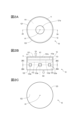
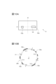
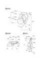
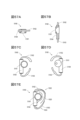
- FIG. 1 is a transparent perspective view illustrating the configuration of the acoustic signal output device of the first embodiment.
- FIG. 2A is a transparent plan view illustrating the configuration of the acoustic signal output device of the first embodiment.
- FIG. 2B is a transparent front view illustrating the configuration of the acoustic signal output device of the first embodiment.
- FIG. 2C is a bottom view illustrating the configuration of the acoustic signal output device of the first embodiment.
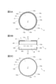
- FIG. 3A is an end view 2BA--2BA of FIG. 2B.
- FIG. 3B is an end view 2A-2A of FIG. 2A.
- FIG. 3C is an end view 2BC-2BC of FIG. 2B.
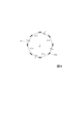
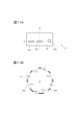
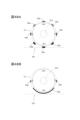
- FIG. 4 is a conceptual diagram illustrating the arrangement of sound holes.
- FIG. 4 is a conceptual diagram illustrating the arrangement of sound holes.
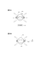
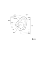
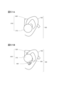
- FIG. 5A is a diagram for illustrating a usage state of the acoustic signal output device of the first embodiment
- FIG. 5B is a diagram for illustrating observation conditions for an acoustic signal emitted from the acoustic signal output device of the first embodiment.
- FIG. 6 is a graph illustrating frequency characteristics of acoustic signals observed at position P1 in FIG. 5B.
- FIG. 7 is a graph illustrating frequency characteristics of acoustic signals observed at position P2 in FIG. 5B.
- FIG. 8 is a graph illustrating the difference between the acoustic signal observed at position P1 and the acoustic signal observed at position P2.
- 9A and 9B are graphs illustrating the relationship between the area ratio of sound holes and sound leakage.
- FIG. 10A is a front view for illustrating the arrangement of sound holes.
- FIG. 10B is a conceptual diagram illustrating the arrangement of sound holes.
- FIG. 11A is a front view for illustrating the arrangement of sound holes.
- FIG. 11B is a conceptual diagram illustrating the arrangement of sound holes.
- 12A to 12C are front views for illustrating modifications of the arrangement of sound holes.
- 13A and 13B are transparent plan views for illustrating modifications of the arrangement of sound holes.
- 14A and 14B are conceptual diagrams for illustrating modifications of the arrangement of sound holes.
- FIG. 15A is a transparent front view for illustrating a modification of the arrangement of sound holes.
- FIG. 15B is an end view for illustrating a modification of the arrangement of the sound holes and a modification of the distance between the driver unit and the housing.
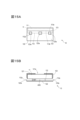
- FIG. 16A to 16C are end views for illustrating modifications of the acoustic signal output device of the first embodiment.
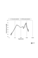
- FIG. 17 is a graph comparing frequency characteristics of acoustic signals observed at position P1 in FIG. 5B.
- FIG. 18 is a graph illustrating frequency characteristics of acoustic signals observed at position P2 in FIG. 5B.
- FIG. 19 is a graph illustrating the difference between the acoustic signal observed at position P1 and the acoustic signal observed at position P2.
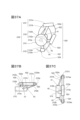
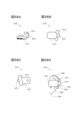
- FIG. 20 is a transparent perspective view illustrating the configuration of the acoustic signal output device of the second embodiment.
- FIG. 21A is a transparent plan view illustrating the configuration of the acoustic signal output device of the second embodiment.
- FIG. 21B is a transparent front view illustrating the configuration of the acoustic signal output device of the first embodiment.
- FIG. 21C is a bottom view illustrating the configuration of the acoustic signal output device of the first embodiment;
- FIG. 22A is an end view 21A-21A of FIG. 21B.
- FIG. 22B is a cross-sectional view taken along line 21B-21B of FIG. 21A.
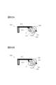
- 23A and 23B are diagrams for exemplifying the state of use of the acoustic signal output device of the second embodiment.
- FIG. 24 is a see-through perspective view illustrating a modification of the acoustic signal output device of the second embodiment.
- FIG. 25A is a transparent plan view illustrating a modification of the acoustic signal output device of the second embodiment.
- FIG. 25B is a transparent front view illustrating a modification of the acoustic signal output device of the second embodiment.
- FIG. 25C is a bottom view illustrating a modification of the acoustic signal output device of the second embodiment;
- FIG. 26 is an end view 25A-25A of FIG. 25B.
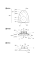
- FIG. 27 is a perspective view illustrating the configuration of the acoustic signal output device of the third embodiment.
- FIG. 28 is a transparent perspective view illustrating the configuration of the acoustic signal output device of the third embodiment.
- FIG. 29 is a conceptual diagram illustrating the arrangement of sound holes.
- 30A to 30C are block diagrams illustrating configurations of circuit units.
- FIG. 31 is a diagram for exemplifying the usage state of the acoustic signal output device of the third embodiment.
- 32A is a perspective view illustrating a modification of the acoustic signal output device of the third embodiment;
- FIG. 32B is a conceptual diagram illustrating a modification of the arrangement of sound holes.
- FIG. 33A is a transparent perspective view illustrating a modification of the acoustic signal output device of the third embodiment;
- FIG. 33B is a diagram illustrating a modification of the acoustic signal output device of the third embodiment;
- FIG. 34A is a diagram for illustrating the configuration of the acoustic signal output device of the fourth embodiment;
- FIG. 34B is a diagram illustrating a modification of the acoustic signal output device of the fourth embodiment
- FIG. 35A is a transparent front view for illustrating the configuration of the acoustic signal output device of the fifth embodiment
- 35B is a transparent plan view for illustrating the configuration of the acoustic signal output device of the fifth embodiment
- FIG. 35C is a transparent right side view for illustrating the configuration of the acoustic signal output device of the fifth embodiment.
- FIG. FIG. 36A is a plan view illustrating the fixing portion of the fifth embodiment
- 36B is a right side view illustrating the fixing portion of the fifth embodiment
- FIG. FIG. 36C is a front view illustrating the fixing portion of the fifth embodiment;
- FIG. 36D is a cross-sectional view 36A-36A of FIG. 36A.
- FIG. 37A is a transparent front view for illustrating a modification of the acoustic signal output device of the fifth embodiment
- 37B is a transparent plan view for illustrating a modification of the acoustic signal output device of the fifth embodiment
- FIG. 37C is a transparent right side view for illustrating a modification of the acoustic signal output device of the fifth embodiment
- FIG. FIG. 38 is a front view for illustrating a modification of the acoustic signal output device of the fifth embodiment
- 39A and 39B are front views illustrating modifications of the acoustic signal output device of the fifth embodiment.
- FIG. 37A is a transparent front view for illustrating a modification of the acoustic signal output device of the fifth embodiment
- 37B is a transparent plan view for illustrating a modification of the acoustic signal output device of the fifth embodiment
- FIG. 37C is a transparent right side view for
- FIG. 40A is a plan view illustrating a modification of the acoustic signal output device of the fifth embodiment
- FIG. 40B is a conceptual diagram illustrating a modification of the arrangement of sound holes.
- FIG. 41A is a plan view illustrating a modification of the acoustic signal output device of the fifth embodiment;
- FIG. 41B is a conceptual diagram illustrating a modification of the arrangement of sound holes.
- FIG. 42 is a transparent front view for illustrating the configuration of the acoustic signal output device of the fifth embodiment.
- FIG. 43A is a rear view for illustrating the configuration of the acoustic signal output device of the fifth embodiment;
- FIG. 43B is a cross-sectional view taken along line 43A-43A of FIG. 43A.
- FIG. 44 is a transparent front view for illustrating a modification of the acoustic signal output device of the fifth embodiment.
- FIG. 45 is a transparent front view for illustrating a modification of the acoustic signal output device of the fifth embodiment.
- FIG. 46A is a transparent front view for illustrating a modification of the acoustic signal output device of the fifth embodiment;
- 46B is a transparent bottom view for illustrating a modification of the acoustic signal output device of the fifth embodiment;
- FIG. 46C is a plan view illustrating a modification of the acoustic signal output device of the fifth embodiment;
- FIG. 47A and 47B are conceptual diagrams for illustrating modifications of the arrangement of sound holes.
- FIGS. 48A and 48B are conceptual diagrams illustrating modifications of the arrangement of sound holes.
- FIG. 49A is a front view illustrating a modification of the acoustic signal output device of the sixth embodiment
- FIG. 49B is a perspective view illustrating a modification of the acoustic signal output device of the sixth embodiment
- FIG. 50A is a perspective view illustrating a modification of the acoustic signal output device of the sixth embodiment
- FIG. 50B is a plan view illustrating a modification of the acoustic signal output device of the sixth embodiment
- FIG. 51A is a plan view illustrating a modification of the acoustic signal output device of the sixth embodiment
- FIG. 51B is a plan view illustrating a modification of the acoustic signal output device of the sixth embodiment
- FIG. 51A is a plan view illustrating a modification of the acoustic signal output device of the sixth embodiment
- FIG. 51B is a plan view illustrating a modification of the acoustic signal output device of the sixth embodiment
- FIG. 49A is a front view illustrating a modification
- FIG. 52A is a plan view illustrating a modification of the acoustic signal output device of the sixth embodiment
- FIG. 52B is a see-through perspective view for illustrating a modification of the acoustic signal output device of the sixth embodiment.
- FIG. 53A is a plan view illustrating a modification of the acoustic signal output device of the sixth embodiment;
- FIG. 53B is a right side view illustrating a modification of the acoustic signal output device of the sixth embodiment;
- FIG. 53C is a front view illustrating a modification of the acoustic signal output device of the sixth embodiment;
- FIG. 53D is a rear view for illustrating a modification of the acoustic signal output device of the sixth embodiment;
- FIG. 53A is a plan view illustrating a modification of the acoustic signal output device of the sixth embodiment
- FIG. 52B is a see-through perspective view for illustrating a modification of the acoustic signal output device of the sixth embodiment.
- FIG. 53E is a front view for illustrating the usage state of the modified example of the acoustic signal output device of the sixth embodiment.
- FIG. 54A is a perspective view illustrating a modification of the acoustic signal output device of the sixth embodiment;
- FIG. 54B is a perspective view illustrating a modification of the acoustic signal output device of the sixth embodiment;
- FIG. 54C is a perspective view illustrating a usage state of the modified example of the acoustic signal output device of the sixth embodiment.
- FIGS. 55A and 55B are front views for illustrating the state of use of the modified example of the acoustic signal output device of the sixth embodiment.
- FIG. 56A is a front view illustrating a modification of the acoustic signal output device of the sixth embodiment;
- FIG. 56A is a front view illustrating a modification of the acoustic signal output device of the sixth embodiment;
- FIG. 56A is a front view illustrating a modification of the acou
- FIG. 56B is a rear view for illustrating a modification of the acoustic signal output device of the sixth embodiment
- FIG. 56C is a front view for illustrating the usage state of the modified example of the acoustic signal output device of the sixth embodiment.
- FIG. 57A is a plan view illustrating a modification of the acoustic signal output device of the sixth embodiment
- FIG. 57B is a right side view illustrating a modification of the acoustic signal output device of the sixth embodiment
- FIG. 57C is a front view illustrating a modification of the acoustic signal output device of the sixth embodiment
- FIG. 57D is a rear view for illustrating a modification of the acoustic signal output device of the sixth embodiment
- FIG. 57E is a front view for illustrating the usage state of the modified example of the acoustic signal output device of the sixth embodiment.
- FIG. 58A is a plan view illustrating a modification of the acoustic signal output device of the sixth embodiment;
- FIG. 58B is a front view illustrating a modification of the acoustic signal output device of the sixth embodiment;
- FIG. 58C is a rear view for illustrating a modification of the acoustic signal output device of the sixth embodiment;
- FIG. 58D is a front view for illustrating the usage state of the modified example of the acoustic signal output device of the sixth embodiment.
- FIG. 59A is a plan view illustrating a modification of the acoustic signal output device of the sixth embodiment;
- FIG. 60A is a left side view illustrating a modification of the acoustic signal output device of the sixth embodiment
- FIG. 60B is a front view illustrating a modification of the acoustic signal output device of the sixth embodiment
- FIG. 60C is a front view for illustrating the usage state of the modified example of the acoustic signal output device of the sixth embodiment.
- FIG. 61A is a plan view illustrating a modification of the acoustic signal output device of the sixth embodiment
- FIG. 61B is a right side view illustrating a modification of the acoustic signal output device of the sixth embodiment
- FIG. 61C is a front view illustrating a modification of the acoustic signal output device of the sixth embodiment
- FIG. 61D is a rear view illustrating a modification of the acoustic signal output device of the sixth embodiment
- FIG. 61E is a front view for illustrating the usage state of the modified example of the acoustic signal output device of the sixth embodiment.
- 62A and 62B are conceptual diagrams illustrating modifications of the acoustic signal output device of the sixth embodiment.
- 63A and 63B are conceptual diagrams illustrating modifications of the acoustic signal output device of the sixth embodiment.
- 64A and 64B are conceptual diagrams illustrating modifications of the acoustic signal output device of the sixth embodiment.
- 65A to 65C are conceptual diagrams illustrating modifications of the acoustic signal output device of the sixth embodiment.
- the acoustic signal output device 10 of the present embodiment is a device for listening to sound (for example, open-ear earphones, headphones, etc.) that is worn without sealing the ear canal of the user.
- an acoustic signal output device 10 of the present embodiment converts an output signal (an electrical signal representing an acoustic signal) output from a playback device into an acoustic signal. It has a driver unit 11 that converts it into a signal and outputs it, and a housing 12 that accommodates the driver unit 11 inside.
- the driver unit (speaker driver unit) 11 emits (sounds) an acoustic signal AC1 (first acoustic signal) based on the input output signal to one side (D1 direction side), and generates a reverse phase signal ( A device (device having a speaker function) that emits an acoustic signal AC2 (second acoustic signal), which is an approximation signal of an inverted phase signal) or an antiphase signal, to the other side (D2 direction side).
- an acoustic signal emitted from the driver unit 11 to one side is called an acoustic signal AC1 (first acoustic signal)
- an acoustic signal emitted from the driver unit 11 to the other side is called an acoustic signal AC1 (first acoustic signal).
- acoustic signal AC2 second acoustic signal
- the driver unit 11 includes a diaphragm 113 that vibrates to emit an acoustic signal AC1 from one surface 113a in the D1 direction, and vibrates to emit an acoustic signal AC2 from the other surface 113b in the D2 direction (FIG. 2B).
- the driver unit 11 of this example emits the acoustic signal AC1 from the surface 111 on one side in the D1 direction by vibrating the diaphragm 113 based on the input output signal, and generates a reverse phase signal of the acoustic signal AC1 or An acoustic signal AC2, which is an approximation signal of the antiphase signal, is emitted from the other side 112 in the direction D2. That is, the acoustic signal AC2 is emitted secondarily with the emission of the acoustic signal AC1.
- the D2 direction (the other side) is, for example, the opposite direction of the D1 direction (one side), but the D2 direction does not have to be strictly the opposite direction of the D1 direction, as long as the D2 direction is different from the D1 direction. good.
- the relationship between one side (D1 direction) and the other side (D2 direction) depends on the type and shape of the driver unit 11 .
- the acoustic signal AC2 may be strictly the anti-phase signal of the acoustic signal AC1, or the acoustic signal AC2 may be an approximation signal of the anti-phase signal of the acoustic signal AC1. .
- the approximation signal of the anti-phase signal of the acoustic signal AC1 may be (1) a signal obtained by shifting the phase of the anti-phase signal of the acoustic signal AC1, or (2) an anti-phase signal of the acoustic signal AC1. It may be a signal obtained by changing (amplifying or attenuating) the amplitude of (3), or a signal obtained by shifting the phase of the anti-phase signal of the acoustic signal AC1 and further changing the amplitude. good.
- the phase difference between the antiphase signal of the acoustic signal AC1 and its approximation signal is preferably ⁇ 1 % or less of one period of the antiphase signal of the acoustic signal AC1.
- Examples of ⁇ 1 % are 1%, 3%, 5%, 10%, 20%, and so on. Moreover, it is desirable that the difference between the amplitude of the antiphase signal of the acoustic signal AC1 and the amplitude of its approximation signal is ⁇ 2 % or less of the amplitude of the antiphase signal of the acoustic signal AC1. Examples of ⁇ 2 % are 1%, 3%, 5%, 10%, 20%, and so on.
- Examples of the system of the driver unit 11 include a dynamic type, a balanced armature type, a hybrid type of a dynamic type and a balanced armature type, and a condenser type. Also, the shapes of the driver unit 11 and the diaphragm 113 are not limited.
- the outer shape of the driver unit 11 has a substantially cylindrical shape with both end faces and the diaphragm 113 has a substantially disk shape is shown, but this is a limitation of the present invention. isn't it.
- the outer shape of the driver unit 11 may be rectangular parallelepiped, and the diaphragm 113 may be dome-shaped.
- Examples of acoustic signals are sounds such as music, voice, sound effects, and environmental sounds.
- the housing 12 is a hollow member having a wall portion on the outside, and accommodates the driver unit 11 inside.
- the driver unit 11 is fixed to the end portion on the D1 direction side inside the housing 12 .
- the shape of the housing 12 is not limited, for example, it is desirable that the shape of the housing 12 is rotationally symmetrical (line symmetrical) or approximately rotationally symmetrical about an axis A1 extending along the D1 direction. This makes it easy to provide the sound holes 123a (details of which will be described later) so that the energy of the sound emitted from the housing 12 does not fluctuate in each direction.
- the housing 12 has a first end surface, which is a wall portion 121 arranged on one side (D1 direction side) of the driver unit 11, and a wall portion 122 arranged on the other side (D2 direction side) of the driver unit 11. and a side surface that is a wall portion 123 that surrounds the space sandwiched between the first and second end surfaces around an axis A1 passing through the first and second end surfaces (FIG. 2B , FIG. 3B).
- the housing 12 has a substantially cylindrical shape with both end faces is shown for the sake of simplicity of explanation.
- the distance between the walls 121 and 122 is 10 mm, and the walls 121 and 122 are circular with a radius of 10 mm.
- the housing 12 may have a substantially dome shape with walls at the ends, a hollow substantially cubic shape, or other three-dimensional shapes.
- the material constituting the housing 12 is not limited.
- the housing 12 may be composed of a rigid body such as synthetic resin or metal, or may be composed of an elastic body such as rubber.
- the acoustic signal AC1 emitted from the sound hole 121a reaches the user's ear canal and is heard by the user.
- an acoustic signal AC2 which is a reverse phase signal of the acoustic signal AC1 or an approximation signal of the reverse phase signal, is emitted.
- Part of the acoustic signal AC2 cancels part of the acoustic signal AC1 emitted from the sound hole 121a (sound leakage component).
- an acoustic signal AC1 (first acoustic signal) is emitted from the sound hole 121a (first sound hole)
- an acoustic signal AC2 (second acoustic signal) is emitted from the sound hole 123a (second sound hole).
- the attenuation rate ⁇ 11 of the acoustic signal AC1 (first acoustic signal) at the position P2 (second point) relative to the position P1 (first point) can be set to a predetermined value ⁇ th or less
- the attenuation ⁇ 12 of the acoustic signal AC1 (first acoustic signal) at the position P2 (second point) with reference to the position P1 (first point) can be made equal to or greater than a predetermined value ⁇ th .
- the position P1 (first point) is a predetermined point at which the acoustic signal AC1 (first acoustic signal) emitted from the sound hole 121a (first sound hole) reaches.
- position P2 (second point) is a predetermined point that is farther from acoustic signal output device 10 than position P1 (first point).
- the predetermined value ⁇ th is a value ( low value). Further, the predetermined value ⁇ th is greater than the attenuation ⁇ 22 due to air propagation of an arbitrary or specific acoustic signal (sound) at the position P2 (second point) relative to the position P1 (first point). value.
- the acoustic signal output device 10 of the present embodiment is designed such that the attenuation rate ⁇ 11 is equal to or less than a predetermined value ⁇ th smaller than the attenuation rate ⁇ 21 , or the attenuation amount ⁇ 12 is It is designed to be equal to or greater than a predetermined value ⁇ th that is greater than the attenuation ⁇ 22 .
- Acoustic signal AC1 is air-propagated from position P1 to position P2, and is attenuated due to this air propagation and acoustic signal AC2.
- the attenuation factor ⁇ 11 is the magnitude AMP 2 (AC1 ) ratio (AMP 2 (AC1)/AMP 1 (AC1)).
- the attenuation ⁇ 12 is the difference (
- the acoustic signal AC2 is not assumed, then any or particular acoustic signal AC ar air propagated from position P1 to position P2 will be attenuated due to air propagation and not due to acoustic signal AC2.
- the attenuation rate ⁇ 21 is the acoustic signal at the position P2 that is attenuated due to air propagation (attenuated without being due to the acoustic signal AC2) with respect to the magnitude AMP 1 (AC ar ) of the acoustic signal AC ar at the position P1.
- the magnitude of AC ar is the ratio of AMP 2 (AC ar ) (AMP 2 (AC ar )/AMP 1 (AC ar )).
- the attenuation ⁇ 22 is the difference (
- An example of the magnitude of the acoustic signal is the sound pressure of the acoustic signal or the energy of the acoustic signal.
- the "sound leakage component” is, for example, an area of the acoustic signal AC1 emitted from the sound hole 121a other than the user wearing the acoustic signal output device 10 (for example, the It means a component that has a high possibility of arriving in humans (other than humans).
- the "sound leakage component” means a component of the acoustic signal AC1 that propagates in directions other than the D1 direction.
- the direct wave of the acoustic signal AC1 is mainly emitted from the sound hole 121a, and the direct wave of the second acoustic signal is mainly emitted from the second sound hole.
- Part of the direct wave of the acoustic signal AC1 emitted from the sound hole 121a (sound leakage component) is canceled by interference with at least part of the direct wave of the acoustic signal AC2 emitted from the sound hole 123a.
- the arrangement configuration of the sound holes 121a and 123a is illustrated.
- the sound hole 121a (first sound hole) of the present embodiment is an area AR1 (first area ) (FIGS. 1, 2A, 2B, and 3B). That is, the sound hole 121a is open facing the D1 direction (first direction) along the axis A1.
- the sound hole 123a (second sound hole) of the present embodiment is located between the area AR1 (first area) of the wall portion 121 of the housing 12 and the D2 direction side of the driver unit 11 (the side where the acoustic signal AC2 is emitted). provided in the area AR3 of the wall 123 that is in contact with the area AR between the area AR2 (second area) of the wall 122 arranged on the other side).
- the direction between the direction D1 (first direction) and the direction opposite to the direction D1 is the direction D12 (second direction) (FIG. 3B).
- the sound hole 123a (second sound hole) is provided on the D1 direction side (first direction side) of the housing 12, and the sound hole 123a (second sound hole) is provided on the D12 direction side (second direction side) of the housing 12.
- the housing 12 has a first end surface, which is a wall portion 121 arranged on one side (D1 direction side) of the driver unit 11, and a wall portion 122 arranged on the other side (D2 direction side) of the driver unit 11.
- the sound hole 121a (first sound hole) is provided on the first end face and the sound hole 123a (second sound hole) is provided on the side surface. is provided. Further, in the present embodiment, no sound hole is provided on the wall portion 122 side of the housing 12 . If a sound hole is provided in the wall portion 122 side of the housing 12, the sound pressure level of the acoustic signal AC2 emitted from the housing 12 exceeds the level necessary to cancel out the sound leakage component of the acoustic signal AC1. This is because the excess amount is perceived as sound leakage.
- the sound hole 121a of this embodiment is arranged on or near the axis A1 along the emission direction (D1 direction) of the acoustic signal AC1.
- the axis A1 of the present embodiment passes through or near the center of a region AR1 (first region) of the wall portion 121 arranged on one side (D1 direction side) of the driver unit 11 of the housing 12 .
- the axis A1 is an axis that passes through the central region of the housing 12 and extends in the D1 direction. That is, the sound hole 121a of this embodiment is provided at the center position of the area AR1 of the wall portion 121 of the housing 12 .
- the shape of the edge of the open end of the sound hole 121a is circular (the open end is circular) is shown for the sake of simplicity of explanation.
- the radius of such sound holes 121a is, for example, 3.5 mm.
- the shape of the edge of the open end of the sound hole 121a may be oval, square, triangular, or any other shape.
- the open end of the sound hole 121a may be meshed. In other words, the open end of the sound hole 121a may be composed of a plurality of holes.
- the sound hole 123a (second sound hole) of the present embodiment is desirably arranged in consideration of, for example, the following points of view.
- Viewpoint of position The sound hole 123a is arranged so that the propagation path of the acoustic signal AC2 emitted from the sound hole 123a overlaps the propagation path of the sound leakage component of the acoustic signal AC1 to be canceled.
- Viewpoint of area The propagation region of the acoustic signal AC2 emitted from the sound hole 123a and the frequency characteristics of the housing 12 differ according to the opening area of the sound hole 123a.
- the frequency characteristics of the housing 12 affect the frequency characteristics of the acoustic signal AC2 emitted from the sound hole 123a, that is, the amplitude at each frequency.
- the sound leakage component is canceled by the acoustic signal AC2 emitted from the sound hole 123a in the region where the sound leakage component is to be canceled.
- the opening area of the sound hole 123a is determined so that From the above point of view, for example, it is desirable that the sound hole 123a (second sound hole) is configured as follows. For example, as illustrated in FIGS.
- the sound hole 123a (second sound hole) of the present embodiment is centered on the axis A1 along the emission direction of the acoustic signal AC1 (first acoustic signal). It is desirable to provide a plurality of them along the circumference (circle) C1.
- the acoustic signal AC2 is emitted radially (radially about the axis A1) to the outside from the sound holes 123a.
- the sound leakage component of the acoustic signal AC1 is also emitted radially (radially about the axis A1) to the outside from the sound hole 121a.
- the sound leakage component of the acoustic signal AC1 can be offset appropriately by the acoustic signal AC2.
- a plurality of sound holes 123a are provided on the circumference C1 for simplification of explanation.
- the sound hole 123a (second sound hole) provided along the first arc area which is one of the unit arc areas
- the total opening area is the same or substantially the same as the total opening area of the sound holes 123a (second sound holes) provided along the second arc area, which is one of the unit arc areas excluding the first arc area.
- the total opening area of the sound holes 123a (second sound holes) provided along the first circular arc region is equal to that of the unit circular arc region excluding the first circular arc region. It is the same or substantially the same as the total opening area of the sound holes 123a (second sound holes) provided along any second arc area (for example, the unit arc area C1-2).
- the circumference C1 is equally divided into four unit arc regions C1-1, . isn't it.
- " ⁇ 1 and ⁇ 2 are substantially the same” means that the difference between ⁇ 1 and ⁇ 2 is ⁇ % or less of ⁇ 1. Examples of ⁇ % are 3%, 5%, 10%, and so on.
- the sound pressure distribution of the acoustic signal AC2 emitted from the sound hole 123a provided along the first arc area and the sound pressure distribution of the acoustic signal AC2 emitted from the sound hole 123a provided along the second arc area The sound pressure distribution of AC2 is point-symmetrical or substantially point-symmetrical with respect to the axis A1.
- the total sum of the opening areas of the sound holes 123a (second sound holes) provided along each unit arc area is the same or substantially the same.
- the sound pressure distribution of the acoustic signal AC2 emitted from the sound hole 123a becomes point-symmetrical or substantially point-symmetrical with respect to the axis A1.
- the sound leakage component of the acoustic signal AC1 can be offset more appropriately by the acoustic signal AC2.
- the plurality of sound holes 123a are provided along the circumference C1 with the same shape, the same size, and the same intervals.
- a plurality of sound holes 123a having a width of 4 mm and a height of 3.5 mm are provided along the circumference C1 with the same shape, the same size, and the same intervals.
- the sound hole 123a (second sound hole) is provided in a wall portion that contacts the area AR located on the other side (D2 direction side) of the driver unit 11 (FIG. 3B).
- the direct wave of the acoustic signal AC2 emitted from the other side of the driver unit 11 is efficiently led out from the sound hole 123a.
- the sound leakage component of the acoustic signal AC1 can be offset more appropriately by the acoustic signal AC2.
- the ratio S2 /S1 of the sum of the opening areas of the sound holes 123a (second sound holes) to the sum S1 of the opening areas of the sound holes 121a (first sound holes) is 2 /3 ⁇ S2 / S1. It is desirable to satisfy ⁇ 4 (details will be described later). Thereby, the sound leakage component of the acoustic signal AC1 can be appropriately canceled by the acoustic signal AC2.
- the sound leakage suppression performance may also depend on the ratio between the area of the wall portion 123 in which the sound hole 123a is provided and the opening area of the sound hole 123a.
- the housing 12 has a first end surface, which is a wall portion 121 arranged on one side (D1 direction side) of the driver unit 11, and a wall portion 122 arranged on the other side (D2 direction side) of the driver unit 11. , and the space sandwiched between the first and second end faces is centered on the axis A1 along the emission direction (D1 direction) of the acoustic signal AC1 passing through the first and second end faces.
- the ratio S 2 /S 3 of the sum S 2 of the opening area of the sound holes 123a to the total area S 3 of the side surfaces is preferably 1/20 ⁇ S 2 /S 3 ⁇ 1/5 ( Details will be described later).
- Acoustic signal AC1 is emitted from sound hole 121a, emitted acoustic signal AC1 enters right ear 1010 and left ear 1020, and is heard by user 1000.
- FIG. On the other hand, from the sound hole 123a, an acoustic signal AC2, which is a reverse phase signal of the acoustic signal AC1 or an approximation signal of the reverse phase signal, is emitted. Part of the acoustic signal AC2 cancels part of the acoustic signal AC1 emitted from the sound hole 121a (sound leakage component).
- the solid line graph illustrates frequency characteristics when using the acoustic signal output device 10 of the present embodiment
- the dashed line graph illustrates frequency characteristics when using a conventional acoustic signal output device (open-ear earphone). do.
- a conventional acoustic signal output device open-ear earphone
- FIG. 8 when the acoustic signal output device 10 of the present embodiment is used, compared with the case of using the conventional acoustic signal output device, the acoustic signal observed at the position P1 and the acoustic signal observed at the position P2 It can be seen that the difference from the sound pressure of the acoustic signal is large. This indicates that the sound leakage at the position P2 can be suppressed in the acoustic signal output device 10 of the present embodiment as compared with the conventional acoustic signal output device.
- FIG. 9A shows the ratio S2/S1 of the total opening area of the sound hole 123a (second sound hole) to the total S1 of the opening area of the sound hole 121a (first sound hole), and the ratio S2 / S1 of the total opening area of the sound hole 121a (first sound hole).
- 2 illustrates the relationship between the difference between the frequency characteristics of the acoustic signal observed at position P2 and the frequency characteristics of the acoustic signal observed at position P2.
- the horizontal axis indicates the ratio S2 / S1
- the vertical axis indicates the sound pressure level (SPL) [dB] representing the difference.
- r12h6 shows the result when the number of sound holes 121a is 6 and the number of sound holes 123a is 4, and r12h12 shows the result when the number of sounds 21a is 12 and the number of sound holes 123a is 4.
- r45h35 illustrates the result when the number of sound holes 121a is one and the number of sound holes 123a is four. As illustrated in FIG.
- FIG. 9A shows the ratio S2 / S3 of the sum S2 of the opening area of the sound hole 123a (second sound hole) to the total side area S3 , the frequency characteristics of the acoustic signal observed at the position P1, and the position P2.
- the horizontal axis indicates the ratio S2 / S3
- the vertical axis indicates the sound pressure level (SPL) [dB] representing the difference.
- SPL sound pressure level
- the meanings of r12h6, r12h12 and r45h35 are the same as in FIG. 9A.
- the ratio S2 / S3 of the total opening area S2 of the sound hole 123a (second sound hole) to the total side area S3 is 1/20 ⁇ S2 / S3 ⁇ 1. It can be seen that in the range of /5, the difference in sound pressure between the acoustic signal observed at the position P1 and the acoustic signal observed at the position P2 is particularly large. This indicates that the sound leakage suppression effect is great in this range.
- FIGS. 10A, 10B, 11A, 11B, and 12A a plurality of sound holes 123a having different shapes and intervals may be provided in the wall portion 123 along the circumference C1.
- 12B a plurality of sound holes 123a with different intervals may be provided in the wall portion 123 along the circumference C1.
- a second sound hole 123a may be provided in the wall portion 123 along the circumference C1.
- the sound hole 123a provided along the first arc region which is one of the unit arc regions is equal to or substantially the sum of the opening areas of the sound holes 123a provided along the second arc area, which is any of the unit arc areas excluding the first arc area. preferably identical. More preferably, the total sum of the opening areas of the sound holes 123a provided along each unit arc area for each unit arc area is the same or substantially the same. For example, as illustrated in FIGS.
- the number of sound holes 123a provided in each unit arc area C1-1, C1-2, C1-3, and C1-4 Although the sizes are different from each other, the sum of the opening areas of the sound holes 123a provided in the unit arc area C1-1, the sum of the opening areas of the sound holes 123a provided in the unit arc area C1-2, and the unit arc area It is desirable that the sum of the opening areas of the sound holes 123a provided in C1-3 and the sum of the opening areas of the sound holes 123a provided in the unit arc area C1-4 are all the same or substantially the same.
- a plurality of sound holes 123a need only be arranged along the circumference C1, and not all the sound holes 123a are strictly arranged on the circumference C1.
- not all sound holes 123a need be arranged on the circumference C1, and a plurality of sound holes 123a may be arranged along the circumference C1.
- the position of the circumference C1 is not limited to the one exemplified in the first embodiment, and may be any circumference centered on the axis A1.
- all the sound holes 123a need not be arranged along the circumference C1 as long as a sufficient sound leakage suppression effect can be obtained. That is, some of the sound holes 123a may be arranged outside the circumference C1.
- the number of sound holes 123a is not limited as long as a sufficient sound leakage suppression effect can be obtained, and one sound hole 123a may be provided.
- one sound hole is provided at the central position (hereinafter simply referred to as the "central position") of the area AR1 (the wall area arranged on one side of the driver unit) of the wall portion 121 of the housing 12.
- 121a is exemplified.
- a plurality of sound holes 121a may be provided in the region AR1 of the wall portion 121 of the housing 12, and the sound holes 121a may be displaced from the center (central position) of the region AR1 of the wall portion 121 of the housing 12. It may be biased to the eccentric position. For example, as illustrated in FIG.
- one sound hole 121a is located at an eccentric position on the area AR1 (a position on the axis A12 parallel to the axis A1 deviated from the axis A1) (hereinafter simply referred to as "eccentric position").
- eccentric position a position on the axis A12 parallel to the axis A1 deviated from the axis A1
- the position of one sound hole 121a provided in the area AR1 may be biased toward the eccentric position.
- a plurality of sound holes 121a are provided in the area AR1, and the plurality of sound holes 121a are located at eccentric positions on an axis A12 parallel to the axis A1 deviated from the axis A1. It can be biased.
- the positions of the plurality of sound holes 121a provided in the area AR1 may be eccentric. That is, a single sound hole 121a may be provided, or a plurality of sound holes 121a may be provided. may be biased toward Note that the distance between the axis A1 and the axis A2 is not limited, and may be set according to the required sound leakage suppression performance. An example of the distance between axis A1 and axis A2 is 4 mm, but this does not limit the invention.
- the resonance frequency of the housing 12 can be controlled by the arrangement configuration of the sound holes 121a provided in the area AR1 (for example, the number, size, interval, arrangement, etc. of the sound holes 121a).
- the resonance frequency of the housing 12 affects the frequency characteristics of acoustic signals emitted from the sound holes 121a and 123a. Therefore, the frequency characteristics of the acoustic signals emitted from the sound holes 121a and 123a can be controlled by the arrangement configuration of the sound holes 121a provided in the area AR1.
- the resonance frequency of the housing 12 may be controlled by setting the arrangement configuration of the sound holes 121a as shown in Examples 2-1 and 2-2 below.
- the arrangement configuration of the sound holes 121a may be set so that the human auditory sensitivity to the resonance frequency of the housing 12 is low in the high frequency band where it is difficult to suppress sound leakage.
- Sd be the human auditory sensitivity (ease of hearing) to an acoustic signal having a resonance frequency equal to or higher than a predetermined frequency fth of the housing 12 in which the sound hole 121a is located at a certain eccentric position.
- S c is the auditory sensitivity of a human to an acoustic signal having a resonance frequency equal to or higher than a predetermined frequency f th of the housing 12 in which the sound hole 121 a is provided at the center position.
- the auditory sensitivity Sd in this case is lower than the auditory sensitivity Sc . That is, the predetermined frequency f of the housing 12 where the position of the sound hole 121a (first sound hole) is biased to a certain eccentric position (a position deviated from the center of the area of the wall portion arranged on one side of the driver unit)
- the human auditory sensitivity Sd to an acoustic signal having a resonance frequency of th or more is the value obtained when it is assumed that the sound hole 121a is provided at the center position (the center of the wall region arranged on one side of the driver unit).
- the auditory sensitivity may be any indicator as long as it represents the easiness of hearing a sound. The higher the hearing sensitivity, the easier it is to hear.
- An example of auditory sensitivity is the reciprocal of the sound pressure level required for humans to perceive a reference loudness sound. For example, the reciprocal of the sound pressure level at each frequency on the equal loudness curve is the auditory sensitivity.
- the predetermined frequency fth means the lower limit of the frequency band including the frequency at which it becomes difficult to cancel the sound leakage component of the acoustic signal AC1 with the acoustic signal AC2.
- Examples of the predetermined frequency f th are 3000 Hz, 4000 Hz, 5000 Hz, 6000 Hz, and the like.
- the resonance peak of the magnitude of the acoustic signal AC1 and/or the acoustic signal AC2 emitted from the housing 12 may be altered.
- the acoustic signal AC1 emitted from the sound hole 121a and/or the acoustic signal AC2 emitted from the sound hole 123a of the housing 12 in which the position of the sound hole 121a is biased to a certain eccentric position f Let Qd be the sharpness (sharpness) of the peak above th .
- the acoustic signal AC1 first acoustic signal
- the sharpness Qd of the peak of the amplitude of the acoustic signal AC2 second acoustic signal emitted from the sound hole 123a (second sound hole) at a predetermined frequency fth or higher is determined when the sound hole 121a is provided at the center position.
- Acoustic signal AC1 (first acoustic signal) emitted from sound hole 121a (first sound hole) and/or sound emitted from sound hole 123a (second sound hole) of housing 12 when assumed to be It is duller than the peak sharpness Qc of the amplitude of the signal AC2 (second acoustic signal) above the predetermined frequency fth .
- the peak of the magnitude of the acoustic signal AC1 and/or the acoustic signal AC2 emitted from the housing 12 in which the position of the sound hole 121a is biased to a certain eccentric position at a predetermined frequency f th or higher is the sound hole 121a.
- the magnitude of the acoustic signal AC1 and/or the acoustic signal AC2 emitted from the housing 12 is flattened from the peak above the predetermined frequency fth .
- the position of the sound hole 121a may be biased to such an eccentric position.
- the distribution and opening area of the sound holes 123a may be biased accordingly.
- the position of one or more sound holes 121a provided in the area AR1 is biased to an eccentric position on the axis A12 deviated from the axis A1, as illustrated in FIGS. 14A and 14B.
- the opening area of the sound hole 121a provided in the area AR3 may also be biased toward the eccentric position on the axis A12.
- the number of sound holes 123a provided along the unit arc area C1-3 farther from the eccentric position on the axis A12 is greater than that along the unit arc area C1-1 closer to the eccentric position.
- each sound hole 123a is less than the number of sound holes 123a provided in each case.
- the opening area of each sound hole 123a provided along the unit arc region C1-3 far from the eccentric position on the axis A12 is closer to the eccentric position than that. It is smaller than the opening area of each sound hole 123a provided along the unit arc area C1-1. That is, when the circumference C1 is equally divided into a plurality of unit arc regions, the sound hole 123a (the second 2 sound holes) is the sound hole 123a provided along the second arc region (for example, C1-1) which is any of the unit arc regions closer to the eccentric position than the first arc region.
- the distribution of the acoustic signal AC1 emitted from the sound hole 121a to the outside is also biased to the eccentric position.
- the distribution of the acoustic signal AC2 emitted from the sound hole 123a to the outside can also be biased to the eccentric position.
- the sound leakage component of the acoustic signal AC1 can be sufficiently canceled by the emitted acoustic signal AC2.
- the sound hole 121a may be offset from the center (central position) of the area AR1 of the wall portion 121 of the housing 12 to an eccentric position.
- the size of the openings of the sound holes 121 a and 123 , the thickness of the walls of the housing 12 , and the volume inside the housing 12 affect the resonance frequency of the housing 12 . Therefore, by controlling at least part of these, the resonance frequency of the housing 12 can be increased or decreased. That is, the larger the size of the openings of the sound holes 121a and 123, the thinner the thickness of the walls of the housing 12, and the smaller the internal volume of the housing 12, the higher the resonance frequency of the housing 12. can do. Conversely, the smaller the size of the openings of the sound holes 121a and 123, the thicker the wall of the housing 12, and the larger the internal volume of the housing 12, the more the resonance frequency of the housing 12 increases. can be lowered.
- the acoustic signal AC2 which is an antiphase signal of the acoustic signal AC1 or an approximation signal of the antiphase signal, is emitted from the sound hole 123a, and the emitted acoustic signal Part of the acoustic signal AC1 emitted from the sound hole 121a (sound leakage component) is canceled by part of the AC2.
- the direct wave of the acoustic signal AC1 is mainly emitted from the sound hole 121a
- it is preferable that the direct wave of the acoustic signal AC2 is mainly emitted from the sound hole 123a.
- the reflected wave has a different propagation path from the direct wave
- the acoustic signal AC2 emitted from the sound hole 123a includes the reflected wave
- the acoustic signal AC2 emitted from the sound hole 123a is emitted from the sound hole 121a. This is because there is a possibility that a phase different from that of the anti-phase signal or the approximation signal of the anti-phase signal of the received acoustic signal AC1, and the efficiency of canceling the sound leakage component may decrease.
- the housing 12 has an internal structure that suppresses echoes of the acoustic signal AC2 (second acoustic signal) inside the housing 12, and the acoustic signal AC2 is mainly emitted directly from the sound hole 123a (second sound hole).
- a configuration in which waves are emitted is desirable. An example of such a configuration is given below.
- a reverberation suppressing material eg, sponge, paper, etc.
- that suppresses reverberation may be installed in the inner regions (eg, regions AR2 and AR3) of the wall portion of the housing 12 .
- the wall portion of the housing 12 itself may be made of a reverberation suppressing material, or a sheet-like reverberation suppressing material may be fixed to the wall portion of the housing 12 .
- the inner regions (for example, the regions AR2 and AR3) of the wall portion of the housing 12 may be made uneven to suppress echoes.
- a sheet having an uneven surface having a reverberation suppressing effect may be fixed to the inner region of the wall of the housing 12 .
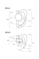
- Example 3-2 As illustrated in FIGS. 15A and 15B, the open end of the sound hole 123a (second sound hole) faces the edge portion 112a on the other side 112 (D2 direction side) of the driver unit 11, and the sound hole 123a A direct wave of the acoustic signal AC2 (second acoustic signal) emitted mainly from the other side 112 of the driver unit 11 may be emitted.
- the wall portion 122 (area AR2) arranged on the other side of the driver unit 11 is out of contact with the driver unit 11 (non-contact while the driver unit 11 is driven), and 11 and the wall portion 122 arranged on the other side 112 of the driver unit 1 is 5 mm or less, and the acoustic signal AC2 (second acoustic signal ) may be a configuration in which a direct wave is emitted.
- the fact that the area AR2 is out of contact with the driver unit 11 while the driver unit 11 is driving means, for example, that the distance dis1 is greater than the amplitude of the other side 112 of the driver unit 11 during driving.
- the housing 12 may be provided with a sound absorbing material that absorbs high-frequency acoustic signals.
- This sound absorbing material has a characteristic that the sound absorption coefficient for the sound signal of frequency f1 is larger than the sound absorption coefficient for the sound signal of frequency f2 .
- frequency f 1 is higher than frequency f 2 (f 1 >f 2 ). That is, the sound absorbing material suppresses the high frequency components of the acoustic signal more than the low frequency components.
- the frequency f1 is less than or equal to the predetermined frequency f2th
- the frequency f2 is greater than the predetermined frequency f2th .
- Examples of the predetermined frequency f2 th are 3000 Hz, 4000 Hz, 5000 Hz and 6000 Hz.
- E in is the energy of the sound signal input to the sound absorbing material
- E out is the energy of the sound signal reflected by the sound absorbing material or the energy of the sound signal passing through the sound absorbing material.
- the sound absorbing material 13 may be provided in at least one of the sound holes 123a (second sound holes).
- the sound holes 123a may be filled with the sound absorbing material 13 .
- At least one of the inside and outside of at least one of the sound holes 123 a may be covered with the sound absorbing material 13 .
- the sound absorbing material 13 may be provided in a region on the other side 112 (D2 direction side) of the driver unit 11 inside the housing 12 .
- the sound absorbing material 13 may be fixed to the area AR2 of the wall portion 122 arranged on the other side 112 (D2 direction side) of the driver unit 11 .
- the sound absorbing material 13 may be fixed inside the wall portion 123 .
- a sound absorbing material 13 is provided in at least one of the sound holes 123a (second sound holes), and the sound absorbing material 13 is provided in a region on the other side 112 (D2 direction side) of the driver unit 11 inside the housing 12.
- the sound absorbing material 13 may be fixed to the area AR ⁇ b>2 of the wall portion 122 .
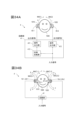
- the acoustic signal output devices 10 were attached to both ears of a dummy head 1100 imitating a human head, and acoustic signals were observed at positions P1 and P2.
- a position P1 is a position near the left ear 1120 of the dummy head 1100 (near the acoustic signal output device 10), and a position P2 is a position 15 cm outward from the position P1.
- FIG. 17 illustrates the frequency characteristics of the acoustic signal observed at position P1 in FIG. 5B
- FIG. 18 illustrates the frequency characteristics of the acoustic signal observed at position P2 in FIG. 5B
- FIG. 2 illustrates the difference between the frequency characteristics of the acoustic signal observed at position P2 and the frequency characteristics of the acoustic signal observed at position P2.
- the horizontal axis indicates frequency (Frequency [Hz]), and the vertical axis indicates sound pressure level (SPL) [dB]).
- the solid line graph illustrates the frequency characteristics when using the acoustic signal output device 10 in which the sound hole 123a is covered with a sound absorbing material (With acoustic absorbent), and the dashed line graph illustrates the frequency characteristics when using the acoustic signal output device 10 of the first embodiment.
- An example of the frequency characteristics in the case of no acoustic absorption is shown. As exemplified in FIG. 19, in the frequency band of 2000 Hz or higher, the sound signal output device 10 having the sound hole 123a covered with the sound absorbing material is generally better than the sound signal output device 10 having no sound absorbing material.
- the difference in sound pressure between the acoustic signal observed at the position P1 and the acoustic signal observed at the position P2 is greater than in the case of using. This indicates that, in a frequency band of 2000 Hz or higher, the sound leakage at the position P2 can be suppressed more generally when the sound signal output device 10 in which the sound hole 123a is covered with the sound absorbing material is used.
- the size of the driver unit 11 must be increased in order to improve the sound quality of the acoustic signal output device 10 of the first embodiment or its modification.
- the size and weight of the acoustic signal output device 10 itself also increase.
- wearing the acoustic signal output device 10 having a large size and weight near the ear canal increases the burden on the ear and the feeling of a foreign body. Therefore, the housing provided with the sound hole and the driver unit 11 may be separated and connected by a waveguide. As a result, it is possible to increase the size of the driver unit 11 without increasing the size and weight of the housing mounted near the ear canal. A detailed description will be given below.
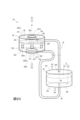
- the acoustic signal output device 20 of the present embodiment is also a device for listening to sound that is worn without sealing the user's ear canal.
- an acoustic signal output device 20 of this embodiment includes a driver unit 11, a housing 22 having hollow portions AR21 and AR22 (first and second hollow portions), and a driver unit 11 inside.
- the driver unit 11 emits an acoustic signal AC1 (first acoustic signal) based on the input output signal to one side (D3 direction side).
- This device emits an acoustic signal AC2 (second acoustic signal), which is an approximation signal of the phase signal, to the other side (D4 direction side).
- the configuration of the driver unit 11 is the same as that of the first embodiment except that the D1 direction is replaced with the D3 direction and the D2 direction is replaced with the D4 direction.
- the housing 23 is a hollow member having a wall portion on the outside, and accommodates the driver unit 11 inside.
- the shape of the housing 23 is not limited, for example, it is desirable that the shape of the housing 23 be rotationally symmetrical (line symmetrical) or substantially rotationally symmetrical about an axis A2 extending along the D3 direction.
- the housing 23 may have a substantially dome shape with walls at the ends, a hollow substantially cubic shape, or other three-dimensional shapes.
- One end 241 of the waveguide 24 is attached to the wall portion 231 of the housing 23 arranged on the surface 111 side (D3 direction side) of the driver unit 11 .
- Waveguide 24 (first waveguide) having one end 241 connected to one side (D3 direction side) of driver unit 11 in this way emits light from surface 111 of driver unit 11 to one side (D3 direction side).
- Acoustic signal AC ⁇ b>1 thus generated is led to the outside of housing 23 .
- One end 251 of the waveguide 25 is attached to the wall portion 232 of the housing 23 arranged on the side of the surface 112 on the other side (D4 direction side) of the driver unit 11 .
- Waveguide 25 (second waveguide) having one end 251 connected to the other side (D4 direction side) of driver unit 11 in this manner emits light from surface 112 of driver unit 11 to the other side (D4 direction side). Acoustic signal AC ⁇ b>2 thus generated is led to the outside of housing 23 .
- the material constituting the housing 23 is not limited.
- the housing 23 may be composed of a rigid body such as synthetic resin or metal, or may be composed of an elastic body such as rubber.
- the waveguides 24 and 25 are, for example, tubular hollow members, and transmit acoustic signals AC1 and AC2 input from one ends 241 and 251 to the other ends 242 and 251, respectively. 252 and emitted from the other end 242,252.
- the waveguides 24 and 25 are not limited to tubular ones, and the acoustic signals collected at one ends 241 and 251 (first position) are transmitted to the other end different from the one ends 241 and 251 (first position). Any structure that leads to 242, 252 (second position) may be used.
- the length of the waveguides 24 and 25 is not limited, preferably, the length of the sound path of the waveguide 24 and the length of the sound path of the waveguide 25 are equal, or the length of the sound path of the waveguide 24 is It is desirable that the difference between the length and the length of the sound path of the waveguide 25 is an integral multiple of the wavelengths of the acoustic signals AC1 and AC2.
- the length of the sound path of the waveguide 24 (first waveguide) is L1
- the length of the sound path of the waveguide 25 (second waveguide) is L2
- n is an integer
- acoustic signal AC1 first acoustic signal
- acoustic signal AC2 second acoustic signal
- a specific example of the length of the sound path of the waveguides 24 and 25 is the length of the waveguides 24 and 25. is.
- the waveguides 24 and 25 may be composed of a rigid body such as synthetic resin or metal, or may be composed of an elastic body such as rubber.
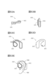
- the joint member 26 has an open end 261 located on one side, a wall portion 262 which is a bottom surface located on the other side of the open end 261, and a space between the open end 261 and the wall portion 263, which is arranged around the axis A1. It is a hollow member having a wall portion 263 which is a side surface surrounding the .
- the axis A1 of this embodiment passes through the open end 261 and the wall portion 263 .
- axis A1 is perpendicular or substantially perpendicular to wall 262 .
- the joining member 26 is rotationally symmetrical with respect to the axis A1.
- the wall portion 263 has a cylindrical shape
- the wall portion 263 may have another shape such as a prismatic shape.
- the other end 242 of the waveguide 24 is attached to the wall portion 263, and the acoustic signal AC1 emitted from the other end 242 of the waveguide 24 is transmitted to the inside of the joint member 26 (between the open end 261 and the wall portion 263). space between). Acoustic signal AC1 introduced into joint member 26 is emitted from open end 261 .
- the material constituting the joint member 26 is not limited.
- the joining member 26 may be composed of a rigid body such as synthetic resin or metal, or may be composed of an elastic body such as rubber.
- the joint member 27 has an open end 271 located on one side, a wall portion 272 which is a bottom surface located on the other side of the open end 271, and a space between the open end 271 and the wall portion 273, which is defined by an axis line. It is a hollow member having a wall portion 273 which is a side surface surrounding A1 at the center.
- the axis A1 of this embodiment passes through the open end 271 and the wall portion 273 .
- axis A1 is perpendicular or substantially perpendicular to wall 272 .
- the joint member 27 is rotationally symmetrical with respect to the axis A1.
- the wall portion 273 may have another shape such as a prismatic shape.
- the other end 252 of the waveguide 25 is attached to the wall portion 273, and the acoustic signal AC2 emitted from the other end 252 of the waveguide 25 is transmitted to the inside of the joint member 27 (between the open end 271 and the wall portion 273). space between). Acoustic signal AC ⁇ b>2 introduced into joint member 27 is emitted from open end 271 .
- the joining member 27 may be composed of a rigid body such as synthetic resin or metal, or may be composed of an elastic body such as rubber.
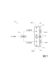
- the housing 22 of the present embodiment includes a wall portion 221 located on one side (D1 direction side) and a wall portion 221 located on the other side (D2 direction side). side), a wall portion 223 surrounding a space between the wall portions 221 and 222, and a space surrounded by the wall portions 221, 222, and 223 is a hollow portion. It has a wall portion 224 separating the AR21 (first hollow portion) and the hollow portion AR22 (second hollow portion).
- the hollow portions AR21 and AR22 are arranged on the same axis A1 extending in the D1 direction.
- the central regions of the hollow portions AR21 and AR22 are arranged on the same axis A1 are placed.
- the inner space of hollow portion AR21 is desirably separated from the inner space of hollow portion AR22 by wall portion 224 .
- a joint member 26 to which the other end 242 of the waveguide 24 is attached is fixed or integrated with the inner wall portion of the hollow portion AR21, and the open end 261 side of the joint member 26 is directed toward the wall portion 221 side.
- the wall portion 262 side of the joint member 26 is fixed to or integrated with the wall portion 224 inside the hollow portion AR21, and the open end 261 side faces the wall portion 221 side.
- the center of the wall portion 262 and the open end 261 of the joining member 26 is arranged on the axis A1.
- the other end 242 of the waveguide 24 is connected to the hollow portion AR21 through the joint member 26, and the acoustic signal AC1 sent to the joint member 26 is transmitted from the open end 261 to the wall portion 221 side (D1 direction side). released towards. That is, for example, the joint member 26 is arranged on the axis A1, the open end 261 of the joint member 26 is opened in the direction D1 (first direction) along the axis A1, and the other end of the waveguide 24 Acoustic signal AC1 introduced from 242 is emitted toward direction D1 inside hollow part AR21.
- a through hole 222a is provided in the wall portion 222 of the hollow portion AR22.
- the through hole 222a is preferably arranged on the axis A1, and more preferably, the center of the through hole 222a is arranged on the axis A1.
- the shape of the through-hole 222a is not limited, but it is preferable that the open portion of the through-hole 222a is rotationally symmetrical with respect to the axis A1, and more preferably, the edge of the open portion of the through-hole 222a is circular.
- a joint member 27 to which the other end 252 of the waveguide 25 is attached is fixed or integrated to the outside of the wall portion 222 of the housing 22, and the open end 271 side of the joint member 27 is directed to the through hole 222a.
- the wall portion 272 of the joining member 27, the open end 271, and the center of the through hole 222a are arranged on the axis A1.
- the other end 252 of the waveguide 25 is connected to the hollow portion AR22 via the joint member 27, and the acoustic signal AC2 sent to the joint member 27 is emitted from the open end 271 toward the inner space of the hollow portion AR22. be done.
- the acoustic signal AC2 is emitted from the open end 271 toward the wall portion 224 side (D1 direction side). That is, for example, the joint member 27 is arranged on the axis A1, and the open end 271 of the joint member 27 is opened in a direction D1 (first direction) along the axis A1, and the other end of the waveguide 25 Acoustic signal AC2 introduced from 252 is emitted toward direction D1 inside hollow part AR22.
- the shape of the housing 22 is not limited, for example, it is desirable that the shape of the housing 22 is rotationally symmetrical or substantially rotationally symmetrical about the axis A1.
- the outer shape of the housing 22 is a substantially cylindrical shape having wall portions 221 and 222 as both end surfaces and a wall portion 223 as a side surface.
- the wall portions 221, 222, and 224 are perpendicular or substantially perpendicular to the axis A1, and the wall portion 223 is parallel or substantially parallel to the axis A1.
- these are only examples and do not limit the present invention.
- the external shape of the housing 22 may be a substantially dome shape with walls at the ends, a hollow substantially cubic shape, or other three-dimensional shapes.
- the material constituting the housing 22 is not limited.
- the housing 22 may be composed of a rigid body such as synthetic resin or metal, or may be composed of an elastic body such as rubber.
- ⁇ Sound holes 221a, 223a> The acoustic signal AC1 (first acoustic signal) introduced into the hollow portion AR21 by the waveguide 24 (first waveguide) is led out to the wall portion 221 of the hollow portion AR21 (first hollow portion). A sound hole 221a (first sound hole) is provided. Further, the wall portion 223 of the hollow portion AR22 (second hollow portion) receives the acoustic signal AC2 (second acoustic signal) introduced into the hollow portion AR22 by the waveguide 25 (second waveguide). 221a (second sound hole) is provided.
- the sound hole 221a and the sound hole 223a are, for example, through-holes passing through the wall of the housing 12, but this does not limit the present invention. do not have.
- the sound hole 221a and the sound hole 223a do not have to be through holes as long as the acoustic signal AC1 and the acoustic signal AC2 can be led out to the outside.
- the acoustic signal AC1 emitted from the sound hole 221a reaches the user's ear canal and is heard by the user.
- the sound hole 223a emits an acoustic signal AC2, which is an anti-phase signal of the acoustic signal AC1 or an approximation signal of the anti-phase signal.
- a portion of the acoustic signal AC2 cancels a portion (sound leakage component) of the acoustic signal AC1 emitted from the sound hole 221a. Thereby, sound leakage can be suppressed.
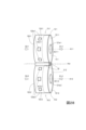
- the arrangement configuration of the sound holes 221a and 223a is illustrated.
- the sound hole 221a (first sound hole) of the present embodiment is provided in the wall portion 221 of the hollow portion AR21 arranged on one side of the joint member 26 (the D1 direction side from which the acoustic signal AC1 is emitted).
- the sound hole 223a (second sound hole) of the present embodiment is provided in the wall portion 223 in contact with the hollow portion AR22. That is, with the center of the hollow portion AR22 as a reference, the direction between the D1 direction (first direction) and the direction opposite to the D1 direction is defined as the D12 direction (second direction) (FIG. 22A).
- the sound hole 223a (second sound hole) is provided on the D1 direction side (first direction side) of the housing 22, and the sound hole 223a (second sound hole) is provided on the D12 direction side (second direction side) of the housing 22. It is That is, the sound hole 221a opens in the D1 direction (first direction) along the axis A1, and the sound hole 223a opens in the D12 direction (second direction).
- the housing 22 has a first end surface that is a wall portion 221 arranged on one side (D1 direction side) of the joint member 26 and a wall arranged on the other side (D2 direction side) of the joint member 26.
- the space sandwiched between the second end surface, which is the portion 222, and the first and second end surfaces is defined by an axis A1 along the emission direction (D1 direction) of the acoustic signal AC1 passing through the first and second end surfaces.
- the sound hole 221a first sound hole
- the sound hole 223a second sound hole
- no sound hole is provided on the wall portion 222 side of the housing 22 .
- the sound pressure level of the acoustic signal AC2 emitted from the housing 22 exceeds the level necessary to cancel out the sound leakage component of the acoustic signal AC1. This is because the excess amount is perceived as sound leakage.
- the sound hole 221a of the present embodiment is arranged on or near the axis A1 along the emission direction (D1 direction) of the acoustic signal AC1.
- the axis A1 of the present embodiment passes through the center of the region of the wall portion 221 arranged on one side (D1 direction side) of the joint member 26 or the vicinity of the center.
- the axis A1 is an axis that passes through the central region of the housing 22 and extends in the D1 direction. That is, the sound hole 221a of this embodiment is provided at the central position of the area of the wall portion 221 of the housing 22 .
- the shape of the edge of the open end of the sound hole 221a is circular (the open end is circular) is shown for the sake of simplicity of explanation.
- the shape of the edge of the open end of the sound hole 221a may be oval, square, triangular, or any other shape.
- the open end of the sound hole 221a may be meshed.
- the open end of the sound hole 221a may be composed of a plurality of holes.
- the wall portion 221 of the housing 22 may be provided with two or more sound holes 221a.
- the sound hole 223a (second sound hole) of the present embodiment has an axis A1 along the emission direction of the acoustic signal AC1 (first acoustic signal). are provided along a circumference C1 centered on .
- an example in which a plurality of sound holes 223a are provided on the circumference C1 is shown for simplification of explanation. However, it is sufficient that the plurality of sound holes 223a are provided along the circumference C1, and not all the sound holes 223a are strictly arranged on the circumference C1.
- the sound hole 223a is provided along the first arc area which is one of the unit arc areas.
- the sum of the opening areas of the (second sound holes) is the opening area of the sound holes 223a (second sound holes) provided along the second arc area, which is any of the unit arc areas excluding the first arc area. is the same or nearly the same as the sum of (FIG. 22B).
- the plurality of sound holes 223a have the same shape, the same size, and the same spacing along the circumference C1.
- this is not a limitation of the invention.
- the shape of the edge of the open end of the sound hole 223a is a square is exemplified, but this does not limit the present invention.
- the shape of the edge of the open end of the sound hole 223a may be a circle, an ellipse, a triangle, or any other shape.
- the open end of the sound hole 223a may be meshed.
- the open end of the sound hole 223a may be composed of a plurality of holes.
- the number of sound holes 223a is not limited, and the wall portion 223 of the housing 22 may be provided with a single sound hole 223a or a plurality of sound holes 223a.
- the ratio S2/ S1 of the sum of the opening areas of the sound holes 223a (second sound holes) to the sum S1 of the opening areas of the sound holes 221a (first sound holes) is 2 / It is desirable to satisfy 3 ⁇ S 2 /S 1 ⁇ 4.
- the outer shape of the housing 22 consists of a first end face, which is a wall portion 221 arranged on one side (D1 direction side) of the joint member 26, and a wall arranged on the other side (D2 direction side) of the joint member 26.
- the space sandwiched between the second end surface, which is the portion 222, and the first and second end surfaces is defined by an axis A1 along the emission direction (D1 direction) of the acoustic signal AC1 passing through the first and second end surfaces. 21B and 22A), the ratio S2 / S3 of the sum of the opening areas S2 of the sound holes 123a to the total area S3 of the side surfaces is 1/20. It is desirable that ⁇ S 2 /S 3 ⁇ 1/5.
- FIGS. 23A and 23B the state of use of the acoustic signal output device 20 is illustrated.
- one acoustic signal output device 20 is attached to each of the user's 1000 right ear 1010 and left ear (not shown). Any mounting mechanism is used for mounting the acoustic signal output device 20 on the ear.
- the housing 22 of the acoustic signal output device 20 is arranged on the side of the ear canal 1011 of the right ear 1010 and the left ear, and the D1 direction side is directed to the ear canal 1011 side of the user 1000 .
- the playback device 210 including the housing 23 is arranged behind the auricle of the right ear 1010 and the left ear, respectively, and the housings 23 and 22 are connected by the waveguides 24 and 25 as described above. .
- An acoustic signal AC1 introduced from the driver unit 11 in the housing 23 into the hollow part AR21 of the housing 22 is emitted from the sound hole 221a, and the emitted acoustic signal AC1 is heard by the user 1000.
- the acoustic signal AC2 introduced from the driver unit 11 inside the housing 23 into the hollow portion AR22 of the housing 22 is emitted from the sound hole 123a.
- a part of the acoustic signal AC2 is an anti-phase signal or an approximation signal of the anti-phase signal of the acoustic signal AC1, and cancels a part (sound leakage component) of the acoustic signal AC1 emitted from the sound hole 221a.
- the playback device 210 including the housing 23 is placed on the head on the front side of the right ear 1010 and the auricle of the left ear, and the housing 23 and the housing 22 are guided as described above. They may be connected by tubes 24,25. Others are the same as the example of FIG. 23A.
- Modification 2 of Second Embodiment In the second embodiment, the configuration in which one sound hole 221a is arranged at the central position of the wall portion 221 of the housing 22 is exemplified.
- a plurality of sound holes 221a may be provided in the region of the wall portion 221 of the housing 22, or the sound holes 221a may be formed in the wall portion 221 of the housing 22. It may be biased to an eccentric position shifted from the center of the region.
- the housing 22 may be provided with sound holes 221a having the same arrangement configuration as the arrangement configuration of the sound holes 121a in Modification 2 of the first embodiment (FIGS. 13A and 13B).
- the distribution and opening area of the sound holes 223a may be biased accordingly. That is, when the circumference C1 is equally divided into a plurality of unit arc areas, the opening area of the sound hole 223a (second sound hole) provided along the first arc area which is one of the unit arc areas may be smaller than the sum of the opening areas of the sound holes 123a provided along the second arc area, which is any unit arc area closer to the eccentric position than the first arc area.
- the housing 22 may be provided with sound holes 223a having the same arrangement configuration as the arrangement configuration of the sound holes 123a in Modification 2 of the first embodiment (FIGS. 14A and 14B).
- the resonance frequency of the housing 22 is controlled by controlling the size of the openings of the sound holes 221a and 223, the thickness of the walls of the housing 22, and at least part of the volume inside the housing 22.
- the acoustic signal output device 20 is provided with a sound absorbing material having a higher sound absorption coefficient for the frequency f 1 sound signal than the sound absorption coefficient for the frequency f 2 (f 1 >f 2 ) sound signal described in the modification 4 of the first embodiment.
- the sound absorbing material may be provided on the other side 112 (D4 direction side) of the driver unit 11 inside the housing 23, or may be provided inside the waveguide 25 (second waveguide). However, it may be provided at the end portion (open end portion) of the waveguide 25, or may be provided in at least one of the sound holes 223a (second sound hole), or may be provided in the hollow portion AR22 (second sound hole). 2 hollow portion).
- the housing 12 is replaced with the hollow part AR22, the sound hole 123a is replaced with the sound hole 223a, and the other side of the driver unit 11 is replaced.
- a configuration in which the region 112 is replaced with the inner region of the hollow portion AR22 and the region AR2 of the wall portion 122 is replaced with the region of the wall portion 222 may be used.
- the emission directions of the acoustic signals AC1 and AC2 in the hollow portions AR21 and AR22 can be controlled.
- the acoustic signal AC1 introduced from the other end 242 of the waveguide 24 is emitted in the direction D1 along the axis A1 inside the hollow portion AR21
- the acoustic signal AC2 introduced from the other end 252 of the waveguide 25 is emitted.
- the sound pressure distributions of the acoustic signal AC1 emitted from the sound hole 221a and the acoustic signal AC2 emitted from the sound hole 223a can be rotationally symmetrical or substantially rotationally symmetrical with respect to the axis A1. This makes it possible to appropriately suppress sound leakage.
- this is not a limitation of the invention.
- the acoustic signal output device 20 does not have the joining member 26, and the other end 242 of the waveguide 24 is directly hollow.
- the acoustic signal AC1 connected to the wall portion 223 of the portion AR21 and sent to the other end 242 of the waveguide 24 may be emitted toward the inside of the hollow portion AR21.
- the acoustic signal output device 20 does not have the joint member 27, and the other end 252 side of the waveguide 25 is directly connected to the wall portion 223 of the hollow portion AR22 to transmit to the other end 252 of the waveguide 25.
- the received acoustic signal AC2 may be emitted toward the interior of the hollow portion AR22.
- the example in which the internal space of the hollow portion AR21 of the housing 22 is separated from the internal space of the hollow portion AR22 by the wall portion 224 is shown. (FIGS. 20, 21B, 22A).
- the internal space of the hollow portion AR21 of the housing 22 does not have to be separated from the internal space of the hollow portion AR22.
- the open end 261 of the joint member 26 faces the wall portion 221 side (D1 direction side) of the housing 22 (for example, the sound hole 221a side), and the open end 271 of the joint member 27 faces the housing 22. It is preferably oriented toward the wall portion 222 side (D2 direction side). Even with such a configuration, the acoustic signal AC1 is emitted from the sound hole 221a, and the acoustic signal AC2 is emitted from the sound hole 223a.
- a plurality of acoustic signal output devices 10 described in the first embodiment or its modification may be provided and controlled independently.
- the sound pressure level of the acoustic signal AC1 emitted from a certain acoustic signal output device 10 and the sound pressure level of the acoustic signal AC2 emitted from the other acoustic signal output device 10 can be independently controlled.
- a certain acoustic signal output device 10 and another acoustic signal output device 10 can be driven in antiphase or substantially antiphase, and the level (power) at each frequency can be controlled independently.
- the sound leakage components of the acoustic signal AC1 of the individual acoustic signal output devices 10 are partially offset by the acoustic signal AC2, and from the different acoustic signal output devices 10 A part of the output acoustic signal AC1 and a part of the acoustic signal AC2 can be offset. As a result, it becomes possible to cancel out sound leakage components more appropriately.
- this embodiment for simplification of explanation, an example in which two acoustic signal output devices 10 are provided for one ear and controlled independently is shown. However, this does not limit the invention, and three or more acoustic signal output devices 10 may be provided for one ear and controlled independently.
- the two acoustic signal output devices 10 are referred to as an acoustic signal output device 10-1 and an acoustic signal output device 10-2. are identical.
- the acoustic signal output device 30 of this embodiment is a device for listening to sound that is worn without sealing the user's external auditory canal. As illustrated in FIGS. 27 and 28, the acoustic signal output device 30 of this embodiment has acoustic signal output devices 10-1 and 2, a circuit section 31, and a connection section 32. FIG.
- the configuration of the acoustic signal output device 10-1 is the same as the acoustic signal output device 10 exemplified in the first embodiment and its modifications. That is, the acoustic signal output device 10-1 has a driver unit 11-1 (first driver unit) and a housing 12-1 (first housing section) housing the driver unit 11-1 therein. .
- the driver unit 11-1 emits an acoustic signal AC1-1 (first acoustic signal) in the D1-1 direction (one side) based on the input output signal I (electrical signal representing the acoustic signal), and D2.
- An acoustic signal AC2-1 (second acoustic signal), which is an anti-phase signal of the acoustic signal AC1-1 (first acoustic signal) or an approximation signal of the anti-phase signal, is emitted to the -1 direction side (the other side).
- the wall portion 121-1 of the housing 12-1 has one or more sound holes 121a-1 (first 1 tone hole) are provided.
- a wall portion 123-1 of the housing 12-1 has one or more sound holes 123a-1 (second 2 sound holes) are provided.
- the details of the configuration of the acoustic signal output device 10-1 are the same as those of the acoustic signal output device 10 described in the first embodiment.
- the sound hole 123a-1 (second sound hole) has a circumference C1- 1 (first circumference) (FIG. 29).
- the circumference C1-1 first circumference
- the The total opening area of the sound hole 123a-1 (second sound hole) is the sound hole 123a-1 provided along the second arc area which is any of the first unit arc areas excluding the first arc area. It is the same or substantially the same as the total opening area of the (second sound holes).
- the configuration of the acoustic signal output device 10-2 is also the same as the acoustic signal output device 10 exemplified in the first embodiment and its modification. That is, the acoustic signal output device 10-2 has a driver unit 11-2 (second driver unit) and a housing 12-2 (second housing section) housing the driver unit 11-2 therein. .
- the driver unit 11-2 emits an acoustic signal AC1-2 (fourth acoustic signal) in the direction of D1-2 (one side) based on the input output signal II (electrical signal representing the acoustic signal).
- An acoustic signal AC2-2 (third acoustic signal), which is an anti-phase signal of the acoustic signal AC1-2 or an approximation signal of the anti-phase signal, is emitted to the -2 direction side (the other side).
- the phase of the acoustic signal AC1-2 (fourth acoustic signal) is the same as or approximates the phase of the acoustic signal AC2-1 (second acoustic signal).
- the phase of the acoustic signal AC2-2 (third acoustic signal) is the same as or approximates the phase of the acoustic signal AC1-1 (first acoustic signal).
- the driver unit 11-2 may have the same design as the driver unit 11-1, or may have a different design from the driver unit 11-1.
- the driver unit 11-2 may be smaller than the driver unit 11-1, or the performance of the driver unit 11-2 may be inferior to that of the driver unit 11-1.
- a wall portion 123-2 of the housing 12-2 has one or more sound holes 123a-2 (third 3 tone holes) are provided.
- a wall portion 121-2 of the housing 12-2 is provided with one or more sound holes 121a-2 (fourth acoustic signal) for leading out the acoustic signal AC1-2 (fourth acoustic signal) emitted from the driver unit 11-2. 4 tone holes) are provided.
- the sound hole 123a-2 (third sound hole) has a circumference C1- 2 (fourth circumference) (FIG. 29).
- the circumference C1-2 fourth circumference
- the The total opening area of the sound hole 123a-2 is the sound hole 123a-2 provided along the fourth unit arc area, which is one of the fourth unit arc areas excluding the third arc area. It is the same or substantially the same as the sum of the opening areas of the (third sound holes).
- the connecting portion 32 fixes the housing 12-1 of the acoustic signal output device 10-1 and the housing 12-2 of the acoustic signal output device 10-2 to each other. are doing.
- the outside of the wall portion 123-1 of the housing 12-1 of the acoustic signal output device 10-1 and the outside of the wall portion 123-2 of the housing 12-2 of the acoustic signal output device 10-2. is joined with.
- the sound hole 121a-1 (first sound hole) opens in a direction D1-1 (first direction) along the axis A1-1.
- the direction D1-1 is a direction along the axis A1-1.
- the sound hole 123a-1 (second sound hole) faces in a direction D12-1 (second direction) between direction D1-1 (first direction) and the direction opposite to direction D1-1 (first direction). is open.
- the sound hole 121a-2 (fourth sound hole) opens in a direction D1-2 (fourth direction) that is the same as or similar to the direction D1-1 (first direction).
- the direction D1-2 is a direction along the axis A1-2.
- the sound hole 123a-2 (third sound hole) faces D12-2 (third direction) between the direction D1-2 (fourth direction) and the opposite direction of direction D1-2 (fourth direction). It's open.
- this arrangement configuration is an example and does not limit the present invention.
- the sound hole 121a-1 (first sound hole) and the sound hole 121a-2 (fourth sound hole) are preferably arranged in the direction D1-1 (first direction ) extending parallel to or substantially parallel to the straight line (axis A1-1).
- the sound hole 123a-1 (second sound hole) and the sound hole 123a-2 (third sound hole) are preferably plane-symmetrical or approximately plane-symmetrical with respect to the reference plane P31.
- housing 12-1 (first housing section) and housing 12-2 (second housing section) are plane-symmetrical or substantially plane-symmetrical with respect to reference plane P31.
- the circuit section 31 uses an input signal, which is an electrical signal representing an acoustic signal, as an input, and outputs an output signal I, which is an electrical signal for driving the driver unit 11-1, and an electrical signal for driving the driver unit 11-2. is a circuit for outputting an output signal II.
- the output signal I and the output signal II are electric signals representing acoustic signals, and the output signal II is an antiphase signal of the output signal I or an approximation signal of the antiphase signal.
- the configuration of the circuit section 31 is exemplified below.
- the circuit section 31 illustrated in FIG. 30A has a phase inverter section 311 which is a phase inverter circuit.
- An input signal input to the circuit section 31 is output as it is as an output signal I and supplied to the driver unit 11-1. Furthermore, the input signal input to the circuit section 31 is also input to the phase inverter section 311 .
- the phase inverter 311 outputs a reverse phase signal of the input signal or an approximation signal of the reverse phase signal as an output signal II.
- the output signal II is supplied to the driver unit 11-2.
- the circuit section 31 illustrated in FIG. 30B has a level correction section 312 , a phase control section 313 and a delay correction section 314 .
- An input signal input to the circuit section 31 is input to the level correction section 312 and the delay correction section 314 .
- the level correction section 312 adjusts the level of each frequency band of the input signal and outputs the resulting band level adjusted signal. That is, if the driver units 11-1 and 11-2 are different in design (aperture, structure, etc.), the frequency characteristics of the acoustic signals output from the driver units 11-1 and 2 are also different. The difference in the frequency characteristics of the acoustic signals output from the driver units 11-1 and 11-2 is related to the canceling effect of sound leakage.
- the acoustic signals output from the driver units 11-1 and 11-2 are adjusted to enhance the effect of sound leakage cancellation. It is desirable that the frequency characteristics are the same. Therefore, it is desirable to adjust the output signals so that the frequency characteristics of the acoustic signals output from the driver units 11-1 and 2 are the same.
- the driver unit 11-1 is arranged in such a way as to enhance the effect of canceling out the sound leakage according to their asymmetry. , 2 to balance the frequency characteristics of the acoustic signals.
- the level correction section 312 realizes these by adjusting the level of each band of the input signal.
- the band level-adjusted signal output from level correction section 312 is input to phase control section 313 .
- Phase control section 313 generates an anti-phase signal of the band level-adjusted signal or an approximation signal of the anti-phase signal, and outputs this as output signal II.
- the phase controller 313 is, for example, a phase inverter circuit or an all-pass filter. When the phase control section 313 is an all-pass filter, the phase characteristic of the level correction section 312 can be taken into consideration to generate an anti-phase signal of the band level-adjusted signal or an approximation signal of the anti-phase signal.
- the output signal II is supplied to the driver unit 11-2. Further, the delay correction unit 314 outputs an output signal I obtained by adjusting the delay amount of the input signal. That is, when a delay occurs in the processing (filter processing) of the level correction section 312 and the phase control section 313, the delay correction section 314 adjusts the amount of delay. As a result, the phases of the acoustic signals output from the driver units 11-1 and 11-2 can be adjusted, and the effect of suppressing sound leakage can be improved.
- the output signal I is supplied to the driver unit 11-1. As described above, in configuration example 2 of the circuit unit 31, the output signal I and the output signal II based on the input signal can be independently controlled.
- the importance of the acoustic signal AC2 for suppressing sound leakage components is low in such a low frequency band. Furthermore, the human hearing sensitivity to acoustic signals with frequencies between 2000 Hz and 6000 Hz is relatively high. In other words, the importance of the acoustic signal AC2 that suppresses the sound leakage component of the acoustic signal AC1 in such a frequency band is high.
- the frequency band of the acoustic signal emitted from the acoustic signal output device 10-1 when the user listens to the acoustic signal AC1 emitted from the sound hole 121a-1 of the acoustic signal output device 10-1, the frequency band of the acoustic signal emitted from the acoustic signal output device 10-2 is , the frequency band of the acoustic signal emitted from the acoustic signal output device 10-1 may be restricted.
- the frequency bandwidth BW-2 of the acoustic signal AC2-2 and the acoustic signal AC1-2 (third acoustic signal and fourth acoustic signal) emitted from the driver unit 11-2 (second driver unit) is
- the frequency bandwidth BW-1 of the acoustic signals AC1-1 and AC2-1 (first acoustic signal and second acoustic signal) emitted from 11-1 (first driver unit) may be narrower than BW-1.
- Example 31-1 For example, the magnitude (level) on the high frequency side of the acoustic signal AC2-2 and the acoustic signal AC1-2 may be suppressed more than the magnitude on the high frequency side of the acoustic signal AC1-1 and the acoustic signal AC2-1. . That is, the component of frequency f 31 (first frequency) or higher of acoustic signals AC2-2 and AC1-2 (third acoustic signal and fourth acoustic signal) emitted from driver unit 11-2 (second driver unit) The magnitude is greater than the magnitude of components of frequency f31 or higher of acoustic signals AC1-1 and AC2-1 (first acoustic signal and second acoustic signal) emitted from driver unit 11-1 (first driver unit).
- the driver unit 11-2 may output the acoustic signal AC2-2 and the acoustic signal AC1-2 in which the frequency band above the frequency f31 is suppressed.
- the frequency f31 are 3000 Hz, 4000 Hz, 5000 Hz, 6000 Hz, and the like.
- Example 31-2 For example, the magnitudes of the audio signals AC2-2 and AC1-2 on the low frequency side may be suppressed more than the magnitudes of the audio signals AC1-1 and AC2-1 on the low frequency side. That is, the components below frequency f 32 (second frequency) of acoustic signals AC2-2 and AC1-2 (third acoustic signal and fourth acoustic signal) emitted from driver unit 11-2 (second driver unit) The magnitude is greater than the magnitude of the components below frequency f32 of the acoustic signals AC1-1 and AC2-1 (first and second acoustic signals) emitted from the driver unit 11-1 (first driver unit). It can be small.
- the driver unit 11-2 may output the acoustic signal AC2-2 and the acoustic signal AC1-2 in which the frequency band below the frequency f32 is suppressed.
- Specific examples of the frequency f32 are 1000 Hz, 2000 Hz, 3000 Hz, and the like.
- Example 31-3 For example, the magnitudes of the audio signal AC2-2 and the audio signal AC1-2 on the high frequency side are suppressed more than the magnitudes of the audio signal AC2-1 and the audio signal AC1-1 on the high frequency side, and the audio signal AC2- 2 and the amplitude of the acoustic signal AC1-2 on the low frequency side may be suppressed more than the amplitude of the acoustic signal AC2-1 and the acoustic signal AC1-1 on the low frequency side.
- the driver unit 11-2 outputs the acoustic signal AC2-2 and the acoustic signal AC1-2 in which the frequency band below the frequency f32 and the frequency band above the frequency f31 are suppressed (for example, frequency f32 and frequency f31 ).
- the circuit section 31 of this example has a level correction section 312 , a phase control section 313 , a delay correction section 314 and a bandpass filter section 315 .
- An input signal input to the circuit section 31 is input to the bandpass filter section 315 and the delay correction section 314 .
- Bandpass filter section 315 obtains and outputs a band-limited signal obtained by limiting (narrowing) the band of the input signal.
- a signal obtained by suppressing the high frequency side of the input signal (for example, the frequency band of frequency f31 or higher) is output as the band-limited signal.
- a signal obtained by suppressing the low-frequency side of the input signal (for example, the frequency band below frequency f32 ) is output as the band-limited signal.
- a signal obtained by suppressing the high frequency side (for example, the frequency band of frequency f31 or higher) and the low frequency side (for example, the frequency band of frequency f32 or lower) of the input signal is used as the band-limited signal. output.
- the band-limited signal is input to level correction section 312 .
- Level correction section 312 adjusts the level of each band of the band-limited signal and outputs the band-level-adjusted signal obtained thereby.
- the band level-adjusted signal output from level correction section 312 is input to phase control section 313 .
- Phase control section 313 generates an anti-phase signal of the band level-adjusted signal or an approximation signal of the anti-phase signal, and outputs this as output signal II.
- the output signal II is supplied to the driver unit 11-2.
- the delay correction unit 314 outputs an output signal I obtained by adjusting the delay amount of the input signal.
- FIG. 31 the state of use of the acoustic signal output device 30 is illustrated.
- One acoustic signal output device 30 is attached to each of the right ear 1010 and the left ear (not shown) of the user 1000 in FIG.
- the D1 direction side of the acoustic signal output device 10-1 of the acoustic signal output device 30 is directed to the ear canal 1011 side of the user 1000.
- FIG. Also, the acoustic signal output device 10-2 is arranged at a position shifted from the external auditory canal 1011.
- the sound hole 121a-1 (first sound hole) is arranged in the direction of the ear canal 1022, and the sound hole 123a-1 (second sound hole) and the sound hole 123a are arranged toward the ear canal 1022.
- -2 third sound hole and sound hole 121a-2 (fourth sound hole) are arranged in a direction other than the external auditory canal 1022.
- Any mounting mechanism is used to mount the acoustic signal output device 30 on the ear.
- the user 1000 listens to the acoustic signal AC1-1 (first acoustic signal) emitted from the sound hole 121a-1 (first sound hole) of the acoustic signal output device 10-1.
- part of the acoustic signal AC2-1 (second acoustic signal) emitted from the sound hole 123a-1 (second sound hole) is the acoustic signal AC1 emitted from the sound hole 121a-1 (first sound hole).
- Cancel part of -1 (first acoustic signal).
- a part of the acoustic signal AC2-2 (third acoustic signal) emitted from the sound hole 123a-2 (third sound hole) is replaced by the acoustic signal AC1 emitted from the sound hole 121a-2 (fourth sound hole).
- -2 (fourth acoustic signal) is partially cancelled.
- a part of the acoustic signal AC2-2 (third acoustic signal) emitted from the sound hole 123a-2 (third sound hole) is replaced with the acoustic signal AC2 emitted from the sound hole 123a-1 (second sound hole).
- -1 second acoustic signal
- part of the acoustic signal AC1-2 (fourth acoustic signal) emitted from the sound hole 121a-2 (fourth sound hole) is the acoustic signal AC1 emitted from the sound hole 121a-1 (first sound hole).
- an acoustic signal AC2-2 (third acoustic signal) is emitted from the sound hole 123a-2 (third sound hole)
- an acoustic signal AC2-2 (third sound hole) is emitted from the sound hole 121a-2 (fourth sound hole).
- Acoustic signals AC1-2 (fourth acoustic signals) are emitted.
- the attenuation rate ⁇ 11 of the acoustic signal AC1-1 (first acoustic signal) at the position P2 (second point) with respect to the position P1 (first point) is It is equal to or less than a predetermined value ⁇ th that is smaller than the attenuation rate ⁇ 21 due to air propagation of the acoustic signal at the reference position P2 (second point).
- the attenuation amount ⁇ 12 of the acoustic signal AC1-1 (first acoustic signal) at the position P2 (second point) with reference to the position P1 (first point) is the position P1 (first point .
- the position P1 (first point) in this embodiment is a predetermined point where the acoustic signal AC1-1 (first acoustic signal) emitted from the sound hole 121a-1 (first sound hole) reaches. be.
- the position P2 (second point) in the present embodiment is a predetermined point that is farther from the acoustic signal output device 30 than the position P1 (first point).
- the sound leakage component from the acoustic signal output device 30 is cancelled.
- the relative level of the driver unit 11-2 with respect to the driver unit 11-1 can be controlled, sound leakage can be reduced more than in the case where one driver unit 11 is used as in the first embodiment. can be reduced.
- the acoustic signal output device 10- 2 when the user listens to the acoustic signal AC1 emitted from the sound hole 121a-1 of the acoustic signal output device 10-1, the acoustic signal output device 10- 2, a sufficient sound leakage suppression effect can be expected by limiting the frequency band of the acoustic signal emitted from the acoustic signal output device 10-1 to a frequency band of the acoustic signal emitted from the acoustic signal output device 10-1.
- the magnitude of the acoustic signal AC2-2 and the acoustic signal AC1-2 on the high frequency side is And when the amplitude of the acoustic signal AC1-1 is suppressed more than the magnitude on the high frequency side, it is possible to suppress the increase in sound leakage on the high frequency side.
- the magnitude of the acoustic signal AC2-2 and the acoustic signal AC1-2 on the low frequency side is greater than the magnitude of the acoustic signal AC2-1 and the acoustic signal AC1-1 on the low frequency side.
- the driver unit 11-2 is smaller than the driver unit 11-1 or has lower performance, a sufficient sound leakage suppression effect can be expected.
- the acoustic signal output devices 10-1 and 10-2 may be the acoustic signal output devices 10 described in the modified example of the first embodiment.
- the position of the sound hole 121a-1 (first sound hole) extends in the direction D1-1 (first sound hole) through the central region of the housing 12-1 (first housing section). direction) extending in the first eccentric position (position on the axis A12-1 parallel to the axis A1-1 deviated from the axis A1-1) deviated from the axis A1-1 (first central axis) .
- FIG. 32A the position of the sound hole 121a-1 (first sound hole) extends in the direction D1-1 (first sound hole) through the central region of the housing 12-1 (first housing section). direction) extending in the first eccentric position (position on the axis A12-1 parallel to the axis A1-1 deviated from the axis A1-1) deviated from the axis A1-1 (first central axis) .
- the first arc area which is one of the first unit arc areas
- the sum of the opening areas of the sound holes 123a-1 (second sound holes) provided along the second circular arc is any of the first unit circular arc regions closer to the first eccentric position than the first circular arc region It may be smaller than the total opening area of the sound holes 123a-1 (second sound holes) provided along the region.
- the position of the sound hole 121a-2 (fourth sound hole) is the axis extending in the direction D1-2 (fourth direction) through the central region of the housing 10-2 (second housing section).
- the third arc area which is one of the second unit arc areas
- the sum of the opening areas of the sound holes 121a-2 (fourth sound holes) provided along the fourth arc is any of the second unit arc areas closer to the fourth eccentric position than the third arc area. It may be smaller than the total opening area of the fourth sound holes provided along the region.
- the sound hole 121a-1 (first sound hole) and the sound hole 121a-2 (fourth sound hole) extend in the direction D1-1 (first direction). It is desirable to have plane symmetry or approximately plane symmetry with respect to a reference plane P31 including a straight line parallel or approximately parallel to the axis A1-1).
- the sound hole 123a-1 (second sound hole) and the sound hole 123a-2 (third sound hole) are preferably plane-symmetrical or approximately plane-symmetrical with respect to the reference plane P31.
- housing 12-1 (first housing section) and housing 12-2 (second housing section) are plane-symmetrical or substantially plane-symmetrical with respect to reference plane P31.
- the sound absorbing material described in the modified example of the first embodiment may be provided in at least one of the acoustic signal output devices 10-1 and 10-2.
- the housing 12-1 (first housing portion) of the acoustic signal output device 10-1 and the housing 12-2 (second housing portion) of the acoustic signal output device 10-2 are integrated. may be modified.
- the housing 12-1 of the acoustic signal output device 10-1 and the housing 12-2 of the acoustic signal output device 10-2 are replaced with an integrated housing 12'', and the driver An area AR31 in which the unit 11-1 is accommodated and an area AR32 in which the driver unit 11-2 is accommodated are partitioned by a wall portion 351 provided inside the housing 12'', and the area AR31 is separated from the area AR32. good too.
- the area AR31 and the area AR32 are partitioned by the wall portion 351, a part of the acoustic signal AC1-1 and a part of the acoustic signal AC1-2 cancel each other inside the housing 12′′.
- the area AR31 and the area AR32 are partitioned by the wall portion 351 to prevent the acoustic signal AC2-1 from being lost and the acoustic signal AC2-2 from canceling each other.
- the area AR31 and the area AR32 need not be partitioned by the wall 351.
- part of the acoustic signals AC1-1 and AC2-1 emitted from the driver unit 11-1 is , sound holes 121a-1, 123a-1, 121a-2, and 123a-2, and the acoustic signals AC1-2 and AC2 emitted from the driver unit 11-2 inside the housing 12′′. May be offset with part of -2.
- the components of the acoustic signals AC1-1, AC2-1, AC1-2, AC2-2 that have not been canceled inside the housing 12′′ are -2, 123a-2 to the outside.
- the components of the acoustic signals AC1-1 and AC2-1 emitted from the driver unit 11-1 that are not canceled inside the housing 12'' is emitted to the outside from any one of 121a-1, 123a-1, 121a-2 and 123a-2.
- They are components of other acoustic signals emitted from any of the driver units 11-1, 2 and emitted to the outside from any of the sound holes 121a-1, 123a-1, 121a-2, 123a-2. Needless to say, it will be offset by some.
- the sound hole 121a-1 (first sound hole) and the sound hole 121a-2 (fourth sound hole) are plane-symmetrical or substantially plane-symmetrical with respect to the reference plane P31.
- the housing 12-1 (first housing section) and housing 12-2 (second housing section) are plane-symmetrical or substantially plane-symmetrical with respect to the reference plane P31. It is desirable to be plane-symmetrical or substantially plane-symmetrical with respect to the reference plane P31.
- the sound absorbing material described in the modified example of the first embodiment is provided inside the housing 12′′ and the sound holes 121a-1, 121a-2, and 123a. -1, 123a-2. Others are the same as those of the third embodiment or its first modification.
- acoustic signal output devices 20-1 and 2 having the same configuration as the acoustic signal output device 20 of the second embodiment may be used.
- the housings 22-1 and 22-2 of the acoustic signal output devices 20-1 and 20-2 are joined by the connecting portion 32, and as described in the second embodiment,
- the housing 22-1 and the housing 23-1 are connected by waveguides 24-1 and 25-1, and the housing 22-2 and the housing 23-2 are connected by waveguides 24-2 and 25-2. may be connected.
- the circuit section 31 supplies an output signal I to the driver unit 11-1 housed in the housing 23-1, and supplies an output signal II to the driver unit 11-2 housed in the housing 23-2.
- the acoustic signal AC1-1 sent from the housing 23-1 to the housing 22-1 through the waveguides 24-1 and 25-1 is emitted from the sound hole 221a-1.
- the acoustic signal AC2-1 is emitted from the sound hole 223a-1.
- the acoustic signal AC1-2 sent from the housing 23-2 to the housing 22-2 through the waveguides 24-2 and 25-2 is emitted from the sound hole 221a-2
- the acoustic signal AC2-2 is It is emitted from the sound hole 223a-2.
- housings 12-1, 12-2, sound holes 121a-1, 121a-2, 123a-1, 123a-2, walls 121-1, 121-2, 122-1, 122-2 , 123-1, 123-2 are provided with housings 22-1, 22-2, sound holes 221a-1, 221a-2, 223a-1, 223a-2, wall portions 221-1, 221-2, 222- 1, 222-2, 223-1, and 223-2 are the same as the third embodiment or its modifications 1 and 2.
- the housing 23-1 may be connected to the housing 22-1 via waveguides 24-1 and 25-1, and connected to the housing 23-1 via waveguides 24-2 and 25-2.
- the circuit section 31 supplies the output signal I to the driver unit 11-1 housed in the housing 23-1.
- Acoustic signal AC1-1 sent from housing 23-1 to housing 22-1 through waveguides 24-1 and 25-1 is emitted from sound hole 221a-1, and acoustic signal AC2-1 is emitted from sound hole 223a. Emitted from -1.
- the acoustic signal AC1-2 sent from the housing 23-1 to the housing 22-2 through the waveguides 24-2 and 25-2 is emitted from the sound hole 221a-2, and the acoustic signal AC2-2 is It is emitted from the sound hole 223a-2.
- the circuit section 31 supplies the output signal I to the driver unit 11-1 housed in the housing 23-1.
- Acoustic signal AC1- ⁇ sent from casing 23-1 to casing 22- ⁇ through waveguides 24- ⁇ and 25- ⁇ is emitted from sound hole 221a- ⁇
- acoustic signal AC2- ⁇ is emitted from sound hole 223a.
- - is released from ⁇ .
- the housing 23-2 and the driver unit 11-2 may be omitted, and the circuit section 31 may not output the output signal II.
- the housing 23-2 and the driver unit 11-2 may not be omitted, and the housing 23-2 may be connected to another housing 22- ⁇ via waveguides 24- ⁇ and 25- ⁇ .
- ⁇ ⁇ max +1 , .
- the output signal II output from the circuit section 31 is further supplied to the driver unit 11-2 accommodated in the housing 22-2, and is transmitted from the housing 23-2 through the waveguides 24- ⁇ and 25- ⁇ .
- the acoustic signal AC1- ⁇ sent to the housing 22- ⁇ is emitted from the sound hole 221a- ⁇
- the acoustic signal AC2- ⁇ is emitted from the sound hole 223a- ⁇ . That is, the acoustic signal AC1-1 (first acoustic signal) emitted from either one or a plurality of driver units may be emitted to the outside from the sound hole 221a-1 (first sound hole).
- the acoustic signal AC2-1 (second acoustic signal) emitted from either the single or plural driver units may be emitted to the outside from the sound hole 123a-1 (second sound hole).
- the acoustic signal AC2-2 (third acoustic signal) emitted from either the single or plural driver units may be emitted from the sound hole 123a-2 (third sound hole).
- the acoustic signal AC1-2 (fourth acoustic signal) emitted from any one of the single or plural driver units may be emitted to the outside from the sound hole 221a-2 (fourth sound hole).
- the acoustic signal AC1-1 (first acoustic signal) and the acoustic signal AC2-2 (third acoustic signal) may be the same signal emitted from the same driver unit, or they may be emitted from different driver units. It may be another signal emitted.
- the acoustic signal AC2-1 (second acoustic signal) and the acoustic signal AC1-2 (fourth acoustic signal) may be the same signal emitted from the same driver unit, or they may be different driver units. may be another signal emitted from the
- the fourth embodiment shows an example in which an acoustic signal output device worn on both ears without sealing the external auditory canal of the user emits monaural acoustic signals whose phases are opposite to each other toward the left and right ears. . From such an acoustic signal output device, part of the monaural acoustic signal is emitted not only to the user's ear canal side but also to the outside of the user. However, since the monaural acoustic signals having phases opposite to each other are emitted, the monaural acoustic signals propagating to the outside of the user cancel each other out, thereby reducing sound leakage.
- the acoustic signal output device 4 of the present embodiment includes an acoustic signal output section 40-1 (first acoustic signal output section) worn on the right ear (one ear) 1010 of the user 1000. , an acoustic signal output section 40 - 2 (second acoustic signal output section) worn on the left ear (the other ear) 1020 , and a circuit section 41 .
- the circuit unit 41 uses an input signal, which is an electric signal representing a monaural sound signal, as an input to generate an output signal I to be supplied to the sound signal output unit 40-1 and an output signal II to be supplied to the sound signal output unit 40-2. It is a circuit that outputs as The circuit section 41 of this embodiment has signal output sections 411 and 412 and a phase inverter section 413 .
- the input signal is input to phase inverter 413 and signal output unit 412 .
- the phase inverting section 413 outputs an output signal I (first output signal) that is an anti-phase signal of the input signal or an approximation signal of the anti-phase signal.
- the signal output section 411 (first signal output section) outputs the output signal I (first output signal) to the acoustic signal output section 40-1 (first acoustic signal output section). That is, signal output section 411 (first signal output section) outputs monaural acoustic signal MAC1 (first output signal I (first output signal) for outputting a monaural sound signal). Further, the signal output unit 412 outputs the input signal as it is to the acoustic signal output unit 40-2 (second acoustic signal output unit) as the output signal II (second output signal).
- signal output unit 412 outputs monaural acoustic signal MAC2 (second monaural acoustic signal) from acoustic signal output unit 40-2 (second acoustic signal output unit) worn on left ear (other ear) 1020.
- output signal II second output signal
- the sound signal output units 40-1 and 40-2 are devices for listening to sound worn on both ears without sealing the external auditory canal of the user.
- An output signal I is input to the acoustic signal output unit 40-1, and the acoustic signal output unit 40-1 converts the output signal I into a monaural acoustic signal MAC1 (a phase that is the same or substantially the same as the phase of the monaural acoustic signal MAC1 is "+"). ) and emitted toward the ear canal of the right ear 1010 .
- the output signal II is input to the acoustic signal output unit 40-2, and the acoustic signal output unit 40-2 converts the output signal II into a monaural acoustic signal MAC2 (the phase of which is the same or substantially the same as the phase of the monaural acoustic signal MAC2 is "-"). ) and emitted toward the external auditory canal of the left ear 1020 .
- the monaural acoustic signal MAC2 is an anti-phase signal of the monaural acoustic signal MAC1 or an approximation signal of an anti-phase signal of the monaural acoustic signal MAC1.
- part of the emitted monaural acoustic signal MAC1 (first monaural acoustic signal) and emitted monaural acoustic signal MAC2 (part of the second monaural acoustic signal) are attached to the right ear 1010 (one ear).
- the outer side of the acoustic signal output unit 40-1 (first acoustic signal output unit) (the outer side of the user 1000, that is, the side opposite to the right ear 1010 side) and/or the left ear 1020 (the other By interfering with each other on the outer side (the outer side of the user 1000, that is, the side opposite to the left ear 1020 side) of the acoustic signal output section 40-2 (second acoustic signal output section) worn on the ear) canceled out.
- the monaural acoustic signal MAC1 (first monaural acoustic signal) is output from the acoustic signal output section 40-1 (first acoustic signal output section), and the acoustic signal output section 40-2 (second acoustic signal output section) outputs a monaural acoustic signal MAC2 (second monaural acoustic signal).
- the attenuation rate ⁇ 11 of the monaural acoustic signal MAC1 (first monaural acoustic signal) at position P2 (second point) with reference to position P1 (first point) is It is equal to or less than a predetermined value ⁇ th that is smaller than the attenuation rate ⁇ 21 due to air propagation of the acoustic signal at the reference position P2 (second point).
- the attenuation amount ⁇ 12 of the first monaural acoustic signal at the position P2 (second point) with respect to the position P1 (first point) is the position P1 (first point) as a reference It is equal to or greater than a predetermined value ⁇ th that is greater than the attenuation amount ⁇ 22 of the acoustic signal due to air propagation at P2 (second point).
- the position P1 (first point) in the present embodiment is a predetermined position reached by the monaural acoustic signal MAC1 (first monaural acoustic signal).
- the position P2 (second point) in this embodiment is a position farther from the acoustic signal output section 40-1 (first acoustic signal output section) than the position P1 (first point). As a result, sound leakage is suppressed.
- Modification 1 of the fourth embodiment instead of the acoustic signal output units 40-1 and 40-2, the acoustic signal output device 10 of the first embodiment or its modification may be used, or the acoustic signal output device 20 of the second embodiment or its modification may be used. may be used.
- the acoustic signal output device 4′ of this modification includes the acoustic signal output device 10-1 (first acoustic signal output section) attached to the right ear (one ear) 1010 of the user 1000. ), an acoustic signal output device 10-2 (second acoustic signal output unit) worn on the left ear (the other ear) 1020, and a circuit unit 41, or the right ear (one ear) of the user 1000 Acoustic signal output device 20-1 (first acoustic signal output unit) attached to ear 1010 and acoustic signal output device 20-2 (second acoustic signal output unit) attached to left ear (other ear) 1020 section) and a circuit section 41 .
- the acoustic signal output device 10-1 or 20-1 (first acoustic signal output unit) emits a monaural acoustic signal MAC1-1 (first acoustic signal, first monaural acoustic signal) in the D1-1 direction (one side). Then, a monaural acoustic signal MAC2-1 (second acoustic signal), which is an anti-phase signal of the monaural acoustic signal MAC1-1 or an approximation signal of the anti-phase signal of the monaural acoustic signal MAC1-1, is emitted to the other side of the D1-1 direction.
- a monaural acoustic signal MAC2-1 second acoustic signal
- driver unit 11-1 (first driver unit), and one or more sound holes 121a-1 or 221a-1 (first sound hole) and one or more sound holes 123a-1 or 223a-1 for leading out the monaural sound signal MAC2-1 (second sound signal) emitted from the driver unit 11-1. (second sound hole) and housing 12-1 or 22-1 (first housing) provided on the wall.
- the acoustic signal output device 10-2 or 20-2 (second acoustic signal output unit) outputs a monaural acoustic signal identical or similar to the monaural acoustic signal MAC2-1 (second acoustic signal) in the D1-2 direction (one side).
- MAC1-2 fourth acoustic signal, second monaural acoustic signal
- monaural acoustic signal MAC2-2 identical or similar to monaural acoustic signal MAC1-1 (first acoustic signal) is emitted to the other side in the D1-2 direction.
- a driver unit 11-2 (second driver unit) that emits (third acoustic signal), and a monaural acoustic signal MAC2-2 (third acoustic signal) emitted from the driver unit 11-2 is derived to the outside.
- a plurality of sound holes 123a-2 or 223a-2 (third sound hole) and a single or a plurality of sounds for leading outside the monaural sound signal MAC1-2 (fourth sound signal) emitted from the driver unit 11-2 housings 12-2 and 22-2 (second housings) having walls provided with holes 121a-2 or 221a-2 (fourth sound holes).
- the acoustic signal AC1-1 (first acoustic signal) is the monaural acoustic signal MAC1-1 (first monaural acoustic signal)
- the acoustic signal AC2-1 is the monaural acoustic signal MAC2-1
- the acoustic signal AC1-2 (fourth acoustic signal) is the monaural acoustic signal MAC1-2 (second monaural acoustic signal)
- acoustic signal AC2-2 is the monaural acoustic signal MAC2-2.
- Other detailed configurations of the acoustic signal output devices 10-1 and 10-2 are the same as the acoustic signal output device 10 of the first embodiment or its modification. Further, the detailed configuration of the acoustic signal output devices 20-1 and 20-2 is the same as the acoustic signal output device 20 of the second embodiment or its modification.
- the sound hole 121a-1 or 221a-1 of the sound signal output device 10-1 or 20-1 is directed toward the right ear 1010 (that is, direction D1-1). is directed to the right ear 1010), and the sound hole 121a-2 or 121a-2 of the sound signal output device 10-2 or 20-2 is directed to the left ear 1020 (that is, the D1-2 direction is directed to the left ear 1020). be done).
- a monaural acoustic signal MAC1-1 (first monaural acoustic signal) is transmitted from the sound hole 121a-1 or 221a-1 of the acoustic signal output device 10-1 or 20-1 (first acoustic signal output section) to the right ear 1010. It is released into the ear canal.
- Monaural acoustic signal MAC1-2 (second monaural acoustic signal) is transmitted to left ear 1020 from sound hole 121a-2 or 221a-2 of acoustic signal output device 10-2 or 20-2 (second acoustic signal output unit). It is released into the ear canal.
- the monaural acoustic signal MAC1-2 is an anti-phase signal of the monaural acoustic signal MAC1-1 or an approximation signal of an anti-phase signal of the monaural acoustic signal MAC1-1.
- the phases of the acoustic signals perceived by the left and right ears are mutually inverted, there is almost no problem in viewing.
- Part of the emitted monaural acoustic signal MAC1-1 and monaural acoustic signal MAC1-2 is also emitted outside both ears, but the monaural acoustic signal MAC1-1 and the monaural acoustic signal MAC1-2 are in opposite phases to each other.
- part of the emitted monaural acoustic signal MAC1-1 (first monaural acoustic signal) and emitted monaural acoustic signal MAC1-2 (part of the second monaural acoustic signal) are combined into the right ear 1010 (one of the and/ Alternatively, the outer side of the acoustic signal output device 10-2 or 20-2 (second acoustic signal output unit) attached to the left ear 1020 (the other ear) (the outer side of the user 1000, that is, the left ear 1020 opposite sides) and are canceled by interfering with each other.
- a monaural acoustic signal MAC2-1 is emitted from the sound hole 123a-1 or 223a-1 of the acoustic signal output device 10-1 or 20-1 (first acoustic signal output section). Part of the emitted monaural acoustic signal MAC2-1 cancels part of the monaural acoustic signal MAC1-1 emitted from the sound hole 121a-1 or 221a-1.
- a monaural acoustic signal MAC2-2 is emitted from the sound hole 123a-2 or 223a-2 of the acoustic signal output device 10-2 or 20-2 (second acoustic signal output section).
- the output signal I and the output signal II in the fourth embodiment or modification 1 of the fourth embodiment may be reversed. That is, the input signal input to the circuit unit 41 is input to the phase inverter 413 and the signal output unit 412, and the phase inverter 413 outputs an output signal II (second output signal) is output to the sound signal output unit 40-2 (second sound signal output unit), and the signal output unit 412 outputs the input signal as it is to the sound signal output unit as the output signal I (first output signal). It may be output to 40-1 (first acoustic signal output unit).
- a method of wearing an ear-mounted acoustic signal output device will be exemplified.
- the conventional wearing method may cause problems such as a heavy burden on the ears and difficulty in stable wearing.
- This embodiment exemplifies a new mounting method of the acoustic signal output device for solving such a problem.
- FIGS. 35A to 36D are used to illustrate mounting method 1.
- FIG. As illustrated in FIGS. 35A to 35C, the acoustic signal output device 2100 of wearing method 1 holds a housing 2112 that emits an acoustic signal and the housing 2112, and is part of the auricle 1020.
- the upper part 1022 of the auricle 1020 holds the mounting part 2121 (first mounting part) configured to be mounted on the upper part 1022 (first auricle part) of the auricle 1020 and the housing 2112 .
- a mounting portion 2122 configured to be mounted on an intermediate portion 1023 (second auricle portion) that is a part of the auricle 1020 different from the (first auricle portion); have.
- the intermediate portion 1023 is an intermediate portion between the upper portion 1022 (helix side) and the lower portion 1024 (earlobe side) of the auricle 1020 .
- the auricle 1020 is the auricle of a human is shown, but the auricle 1020 may be the auricle of an animal other than humans (such as a chimpanzee).
- the housing 2112 in this example may be any of the housings 12, 12'', and 22 exemplified in the first to fourth embodiments and their modifications, or may be a conventional earphone or the like that emits an acoustic signal.
- the housing 2112 When the acoustic signal output device 2100 is worn, the housing 2112 has a sound hole 2112a directed toward the ear canal 1021 and the ear canal 1021 is not blocked. are arranged as follows.
- the mounting portion 2121 (first mounting portion) in this example includes a fixing portion 2121a (first fixing portion) for gripping the helix 1022a (end portion) of the upper portion 1022 (first auricle portion) of the auricle 1020, and a fixing portion 2121a (first fixing portion). and a support portion 2121b that fixes the portion 2121a (first fixing portion) to the housing 2112 .
- One end of the support portion 2121b holds a specific region of the outer wall portion of the fixed portion 2121a, and the other end of the support portion 2121b holds a specific region H1 (first holding region) of the outer wall portion of the housing 2112.
- the support portion 2121b may be fixed to a specific region of the wall of the fixing portion 2121a, or may be integrated with the wall of the fixing portion 2121a in the specific region.
- the other end of the support portion 2121b may be fixed to a specific region H1 of the outer wall of the housing 2112, or integrated with the outer wall of the housing 2112 at the specific region H1.
- the support portion 2121b holds the housing 2112 from the outer side (first outer side) of the specific region H1 of the wall portion of the housing 2112 .
- the outer side (first outer side) of the region H1 is the upper portion 1022 side of the auricle 1020 when the fixing portion 2121a is attached to the helix 1022a.
- the fixing part 2121a (first fixing part) is configured to grip the helix 1022a of the upper portion 1022 (first auricle portion) of the auricle 1020 from above the auricle 1020.
- the housing 2112 is configured to be suspended by a mounting portion 2121 (first mounting portion) including a fixing portion 2121a (first fixing portion) that grips the helix 1022a. That is, the fixing part 2121a holds the helix 1022a from above the auricle 1020, and the housing 2112 is suspended by the other end of the supporting part 2121b that holds the fixing part 2121a at one end.
- the reaction force against the weight of the housing 2112 suspended in this manner is supported by the inner wall surface of the fixed portion 2121a.
- this reaction force is supported by the inner wall surface of the fixed portion 2121a arranged perpendicularly or substantially perpendicularly to the direction of the reaction force.
- the weight of the housing 2112 can be supported even if the holding force of the fixing portion 2121a is small.
- the smaller the gripping force of the fixing portion 2121a the smaller the burden on the auricle 1020, so the burden on the ear can be reduced.
- the fixing portion 2121a may have any specific shape.
- An example of the fixing portion 2121a is a member that has a hollow shape with a C-shaped or U-shaped cross section and is configured to hold the helix 1022a while the helix 1022a is in contact with the inner wall surface 2121aa (for example, , FIGS. 36A to 36D).
- the fixing part 2121a having an ear cuff shape can be exemplified.
- the mounting part 2122 (second mounting part) of this example includes a fixing part 2122a (second fixing part) for gripping the end of the intermediate part 1023 (second auricle part) of the auricle 1020, and a fixing part 2122a (second 2 fixing portion) to the housing 2112;
- One end of the support portion 2122b holds a specific region of the outer wall portion of the fixed portion 2122a, and the other end of the support portion 2122b holds a specific region H2 (second holding region) of the outer wall portion of the housing 2112.
- holding Region H2 differs from region H1 described above.
- One end of the support portion 2122b may be fixed to a specific region of the wall of the fixing portion 2122a, or may be integrated with the wall of the fixing portion 2122a in the specific region.
- the other end of the support portion 2122b may be fixed to a specific region H2 of the outer wall of the housing 2112, or integrated with the outer wall of the housing 2112 at the specific region H2. may be
- the support portion 2122b holds the housing 2112 from the outer side (the second outer side different from the first outer side) of the specific region H2 of the wall portion of the housing 2112 .
- the outer side (second outer side) of the region H2 is the intermediate portion 1023 side of the auricle 1020.
- the housing 2112 is held on the upper portion 1022 of the auricle 1020 from the outer side (first outer side) of the region H1 by the mounting portion 2121 (first mounting portion) as described above, and is further mounted. It is held by the middle portion 1023 of the auricle 1020 from the outer side of the region H2 (second outer side different from the first outer side) by the portion 2122 (second mounting portion). This stabilizes the position of housing 2112 attached to auricle 1020 .
- the housing 2112 is held at mutually different parts (upper part 1022 and middle part 1023) of the auricle 1020 by the mounting part 2121 (first mounting part) and the mounting part 2122 (second mounting part). , the burden on the auricle 1020 due to wearing can be dispersed. Furthermore, the housing 2112 is attached to the auricle 1020 by attachment portions 2121 and 2122 that grip the ends of the auricle 1020 . Such mounting parts 2121 and 2122 do not interfere with the temples of spectacles or the strings of the mask that are hooked on the back side of the auricle 1020 . Note that the fixing portion 2122a may have any specific shape.
- An example of the fixing part 2122a is a member that has a hollow shape with a C-shaped or U-shaped cross section and is configured to hold the intermediate part 1023 of the auricle 1020 while the helix 1022a is in contact with the inner wall surface 2122aa.
- the fixing part 2122a having an ear cuff shape can be exemplified.
- the mounting portion 2121 and the mounting portion 2122 may be composed of a rigid body such as synthetic resin or metal, or may be composed of an elastic body such as rubber.
- FIGS. 37A to 37C are used to illustrate mounting method 2.
- FIG. As illustrated in FIGS. 37A to 37C , the acoustic signal output device 2100′ of the wearing method 2 is the acoustic signal output device 2100 of the wearing method 1, and the upper part 1022 (first auricle part) of the auricle 1020 and A mounting portion 2123 (second mounting portion) configured to be mounted on a lower portion 1024 (second auricle portion) which is a part of the auricle 1020 different from the intermediate portion 1023 (second auricle portion). ) was added.
- the mounting part 2123 (second mounting part) in this example includes a fixing part 2123a (second fixing part) for gripping the end of the lower part 1024 (second auricle part) of the auricle 1020, and a fixing part 2123a ( and a support portion 2123 b fixing the second fixing portion) to the housing 2112 .
- One end of the support portion 2123b holds a specific region of the outer wall portion of the fixed portion 2123a
- the other end of the support portion 2123b holds a specific region H3 (second holding region) of the outer wall portion of the housing 2112.
- holding Region H3 differs from regions H1 and H2 described above.
- One end of the support portion 2123b may be fixed to a specific region of the wall of the fixing portion 2123a, or may be integrated with the wall of the fixing portion 2123a in the specific region.
- the other end of the support portion 2123b may be fixed to a specific region H3 of the outer wall of the housing 2112, or integrated with the outer wall of the housing 2112 at the specific region H3. may be
- the support portion 2123b holds the housing 2112 from the outer side (the second outer side different from the first outer side) of the specific region H3 of the wall portion of the housing 2112 .
- the outer side (second outer side) of the region H3 is the lower portion 1024 side of the auricle 1020. becomes.
- the housing 2112 further extends from the outer side of the region H3 (the second outer side different from the first outer side) to the lower portion 1024 of the auricle 1020 by the mounting portion 2123 (second mounting portion). is held to This further stabilizes the position of housing 2112 attached to auricle 1020 .
- the housing 2112 has a mounting portion 2121 (first mounting portion), a mounting portion 2122 (second mounting portion), and a mounting portion 2123 (second mounting portion), which are different parts of the auricle 1020 (upper portion 1022 and intermediate portion). Since it is held by the portion 1023 and the lower portion 1024), the burden on the auricle 1020 due to wearing can be distributed. Furthermore, the housing 2112 is attached to the auricle 1020 by attaching portions 2121 , 2122 , and 2123 that grip the ends of the auricle 1020 . Such mounting parts 2121 , 2122 , 2123 do not interfere with the temples of spectacles or the strings of the mask that are hooked on the back side of the auricle 1020 .
- the fixing portion 2123a may have any specific shape.
- An example of the fixing part 2123a has a hollow shape with a C-shaped or U-shaped cross section, and is configured to hold the lower part 1024 of the auricle 1020 while the helix 1022a is in contact with the inner wall surface 2123aa. It is a member.
- the fixing part 2123a having an ear cuff shape can be exemplified.
- the material forming the mounting portion 2123 is also not limited.
- ⁇ Wearing method 3> A configuration in which the mounting portion 2122 of the acoustic signal output device 2100' of the mounting method 2 is omitted may be employed.
- the attachment part 2121 of the acoustic signal output device 2100 of the wearing method 1 is hooked on the back side of the upper part 1022 of the auricle 1020 (spectacle temple type). 2224 may be substituted.
- the mounting portion 2224 is a rod-shaped member. One end side of the mounting portion 2224 is bent so as to be hooked on the back side of the upper portion 1022 of the auricle 1020, and the other end holds a specific region H1 (first holding region) of the outer wall portion of the housing 2112. are doing.
- the other end of the mounting portion 2224 may be fixed to a specific region H1 of the outer wall of the housing 2112, or may be integrated with the outer wall of the housing 2112 in the specific region H1. good.
- the mounting portion 2121 of the acoustic signal output device 2100′ of mounting methods 2 and 3 may be replaced with a mounting portion 2224 of a type hooked on the back side of the upper portion 1022 of the auricle 1020.
- the material forming the mounting portion 2224 is not limited.
- the mounting portion 2122 of the acoustic signal output device 2100 of the mounting method 1 sandwiches the end of the intermediate portion 1023 (second auricle portion) of the auricle 1020.
- 2124 (second mounting part) may be substituted.
- the mounting portion 2124 (second mounting portion) includes a fixing portion 2124a (second fixing portion) that sandwiches the end of the intermediate portion 1023 (second auricle portion) of the auricle 1020, and a fixing portion 2124a (second fixing portion). is fixed to the housing 2112, and a support portion 2124b.
- One end of the support portion 2124b holds the end portion of the fixed portion 2124a, and the other end of the support portion 2124b holds a specific region H2 (second holding region) of the outer wall portion of the housing 2112.
- FIG. One end of the support portion 2124b may be fixed to the end of the fixed portion 2124a, or may be integrated with the end of the fixed portion 2124a.
- the other end of the support portion 2124b may be fixed to a specific region H2 of the outer wall of the housing 2112, or may be integrated with the outer wall of the housing 2112 at the specific region H2.
- the support portion 2124b holds the housing 2112 from the outer side (the second outer side different from the first outer side) of the specific region H2 of the wall portion of the housing 2112 .
- the housing 2112 is held by the mounting portion 2121 (first mounting portion) from the outer side (first outer side) of the region H1 to the upper portion 1022 of the auricle 1020 as described above. It is held by the middle portion 1023 of the auricle 1020 from the outer side of the region H2 (second outer side different from the first outer side) by the portion 2124 (second mounting portion). This stabilizes the position of housing 2112 attached to auricle 1020 .
- the housing 2112 is held at different parts (upper part 1022 and intermediate part 1023) of the auricle 1020 by the mounting part 2121 (first mounting part) and the mounting part 2124 (second mounting part). Therefore, the burden on the auricle 1020 due to wearing can be dispersed. Furthermore, the mounting parts 2121 and 2124 do not interfere with the temples of the spectacles or the straps of the mask that are hooked on the back side of the auricle 1020 .
- the holding portion 2124 a (second holding portion) may be configured to hold the lower portion 1024 of the auricle 1020 instead of the intermediate portion 1023 of the auricle 1020 .
- the fixing portion 2124a may have any specific shape.
- the fixing portion 2124a may be a clip-like sandwiching mechanism or an integrated plate spring.
- the material forming the mounting portion 2124 is not limited.
- ⁇ Wearing method 6> Like the acoustic signal output device 2400 illustrated in FIG. 39B , the mounting portion 2121 of the acoustic signal output device 2300 of the wearing method 5 is replaced with the mounting portion 2224 of the type hooked on the back side of the upper portion 1022 of the auricle 1020. good too.
- the configuration of the mounting portion 2224 is the same as that of the mounting method 4.
- the sound holes 121a, 221a (first sound holes) of the housings 12, 12'', 22 ) emitted from the sound holes 123a and 223a (second sound holes ) may be made smaller than the opening areas of the sound holes 123a and 223a (second sound holes) provided at positions away from the shielded area.
- part of the acoustic signal AC1 (first acoustic signal) emitted from the sound holes 121a, 221a (first sound holes) of the housings 12, 12'', 22 is converted into sound holes 123a, 223a (second sound holes).
- the sound leakage is suppressed by the acoustic signal AC2 (second acoustic signal) emitted from the sound hole).
- the sound pressure of the first acoustic signal is small, and the opening area of the sound holes 123a and 223a (second sound holes) provided in or near the shielded area is reduced accordingly, thereby leaking the acoustic signal AC1 to the outside. It is possible to balance the sound pressure distribution (first acoustic signal) and the sound pressure distribution of the acoustic signal AC2 (second acoustic signal) emitted from the sound holes 123a and 223a (second sound holes).
- an acoustic signal AC1 (first acoustic signal) is emitted from the sound holes 121a and 221a (first sound hole)
- an acoustic signal AC2 (second acoustic signal) is emitted from the sound holes 123a and 223a (second sound hole).
- the attenuation rate ⁇ 11 of the acoustic signal AC1 (first acoustic signal) at the position P2 (second point) with respect to the position P1 (first point) is equal to the position P1 (first). It is possible to balance the sound pressure distribution so that the sound pressure distribution is equal to or less than a predetermined value ⁇ th that is smaller than the attenuation rate ⁇ 21 of the acoustic signal due to air propagation at the position P2 (second point) with reference to the second point).
- the attenuation amount ⁇ 12 of the acoustic signal AC1 (first acoustic signal) at the position P2 (second point) with respect to the position P1 (first point) is equal to the position P1 (first point )
- the sound pressure distribution can be balanced so that the sound pressure distribution is equal to or greater than a predetermined value ⁇ th that is larger than the attenuation amount ⁇ 22 of the sound signal due to air propagation at the position P2 (second point).
- the position P1 (first point) here is a predetermined point at which the acoustic signal AC1 (first acoustic signal) emitted from the sound hole 221a (first sound hole) reaches.
- the position P2 (second point) here is a predetermined point that is farther from the sound signal output device than the position P1 (first point).As a result, sound leakage can be effectively suppressed. can be done.
- the housing 2112 is the housing 12 of the first embodiment or its modification, and the housing 12 (the housing 2112) is held by the mounting portions 2121 and 2122 of the mounting method 1 will be described below.
- the housing 2112 may be the housings 12, 12'', 22 exemplified in the second to fourth embodiments and their modifications. It may be held by any one of the mounting portions 2121, 2122, 2123, 2124, and 2224. Also in this case, the following configuration can be applied.
- the acoustic signal output device 2100 in this case emits an acoustic signal AC1 (first acoustic signal) to one side (D1 direction side) and outputs an acoustic signal AC1 to the other side (D2 direction side). It has a driver unit 11 that emits an acoustic signal AC2 (second acoustic signal) that is an anti-phase signal of the (first acoustic signal) or an approximation signal of the anti-phase signal.
- the walls 121 and 123 of the housing 12 are provided with one or more sound holes 121a (first sound holes) for leading the acoustic signal AC1 (first acoustic signal) emitted from the driver unit 11 to the outside. ), and one or more sound holes 123a (second sound holes) for leading the acoustic signal AC2 (second acoustic signal) emitted from the driver unit 11 to the outside.
- first sound holes for leading the acoustic signal AC1 (first acoustic signal) emitted from the driver unit 11 to the outside.
- second sound holes for leading the acoustic signal AC2 (second acoustic signal) emitted from the driver unit 11 to the outside.
- part of the acoustic signal AC2 (second acoustic signal) emitted from the sound hole 123a (second sound hole) is converted to the acoustic signal AC1 (first acoustic signal) emitted from the sound hole 121a (first sound hole).
- the supporting portion 2121b of the mounting portion 2121 holds the region H1 (first holding region) of the wall portion 123 of the housing 12 (housing 2112), and the mounting portion 2122 (second The supporting portion 2122b of the mounting portion) holds the area H2 (second holding area) of the wall portion 123 of the housing 12 (housing 2112).
- the sound hole 121a (first sound hole) is one side (D1 direction side) of a space partitioned by a virtual plane P51 passing through the region H1 (first holding region) and the mounting portion 2122 (second mounting portion).
- the sound hole 123a (second sound hole) is arranged on the other side (D2 direction side) of the space partitioned by the virtual plane P51.
- the acoustic signal AC1 (first acoustic signal) is blocked by the support portion 2121b of the mounting portion 2121 (first mounting portion) or the support portion 2122b of the mounting portion 2122 (second mounting portion) in or near the shielded area AR51.
- the opening area of the provided sound hole 123a (second sound hole) is reduced. That is, as illustrated in FIG. 40B, it is assumed that the sound hole 123a (second sound hole) is provided along the circumference C1 described above.
- the surface of the wall portion 123 of the housing 12 is equally divided into a plurality of unit area areas (unit area areas C5-1, C5-2, C5-3, C5-4 in this example) along the circumference C1.
- the sound hole 123a (second sound hole) provided in the first unit area area (unit area areas C5-2 and C5-3 in this example) that is one of the unit area areas including the shielding area AR51. is any of the unit area areas that do not include the shielding area AR51. ).
- the sound hole 123a (second sound hole) provided in the first unit area area (the unit area areas C5-2 and C5-3 in this example) that is one of the unit area areas including the shielding area AR51
- the total opening area is the sound hole 123a (second smaller than the sum of the opening areas of the sound holes).
- the sound hole 123a (second sound hole) provided in the first unit area area (unit area areas C5-2 and C5-3 in this example) including the shielding area AR51 is smaller than the number of sound holes 123a (second sound holes) provided in the second unit area areas (unit area areas C5-1 and C5-4 in this example) that do not include the shielding area AR51, and A sound hole 123a having an opening area larger than that of the first unit area may be provided in the second unit area.
- the number of sound holes 123a is the same in the first unit area area and the second unit area area, and the opening area of each sound hole 123a provided in the first unit area area is provided in the second unit area area.
- each sound hole 123a It may be smaller than the opening area of each sound hole 123a. Even in such a case, the total opening area of the sound holes 123a (second sound holes) provided in the first unit area area (unit area areas C5-2 and C5-3 in this example) is the second unit area area It is smaller than the total opening area of the sound holes 123a (second sound holes) provided in the regions (unit area regions C5-1 and C5-4 in this example). Even in this way, sound leakage can be effectively suppressed.
- FIGS. 42 and 43A are used to illustrate mounting method 8.
- FIGS. 42 and 43A the acoustic signal output device 2500 of wearing method 8 holds a housing 2112 that emits an acoustic signal and the housing 2112 so as to be worn on the auricle 1020. and a mounting portion 2221 configured.
- the mounting portion 2221 includes a fixing portion 2221a having a concave inner wall surface 2221aa that is configured to be fitted into the upper portion 1022 of the auricle 1020, and an inner wall surface 2221aa side of the fixing portion 2221a that is fitted into the upper portion 1022 of the auricle 1020.
- Shielding wall 2221b configured to cover only a portion of auricle 1020 when closed.
- the fixing part 2221a in this example has a hollow structure that accommodates at least part of the upper part 1022 of the auricle 1020 (for example, the helix 1022a).
- the inner wall surface 2221aa of the fixing portion 2221a is preferably curved.
- the shielding wall 2221b is a plate having a flat or curved wall surface.
- the shielding wall 2221b in this example covers the upper portion 1022 of the auricle 1020 and protects the lower portion 1024 of the auricle 1020 from the outside when the inner wall surface 2221aa side of the fixing portion 2221a is fitted into the upper portion 1022 of the auricle 1020. It is configured in a shape that opens to That is, the end portion 2221c (the end portion opposite to the fixed portion 2221a) of the shielding wall 2221b is the open portion O51.
- the open portion O51 is provided at a position where the lower portion 1024 of the auricle 1020 is opened to the outside when the upper portion 1022 of the auricle 1020 is fitted into the inner wall surface 2221aa side of the fixing portion 2221a.
- the material forming the mounting portion 2221 is also not limited.
- the housing 2112 in this example may be any of the housings 12, 12'', and 22 exemplified in the first to fourth embodiments and their modifications, or may be a conventional earphone or the like that emits an acoustic signal.
- the housing 2112 is held on the inner wall surface 2221bb side of the shielding wall 2221b, and the sound hole 2112a that emits the sound signal faces the direction opposite to the inner wall surface 2221bb.
- the acoustic signal output device 2500 is attached to the auricle 1020, the outer wall surface 2221ba side of the shielding wall 2221b faces outward, and the inner wall surface 2221bb side of the shielding wall 2221b faces inward (toward the auricle 1020).
- the sound hole 2112a of the housing 2112 held by the inner wall surface 2221bb is directed toward the ear canal 1021, and the housing 2112 is arranged so as not to block the ear canal 1021.
- the sound hole 2112a is arranged on the inner side of the shielding wall 2221b, it is possible to suppress the influence of external noise and suppress sound leakage of the acoustic signal emitted from the sound hole 2112a. Since only the auricle 1020 is covered (the lower portion 1024 side of the auricle 1020 is not blocked), external sounds are not completely blocked, and the user can also hear external sounds.
- the acoustic signal output device 2500′ of mounting method 9 is a modification of the acoustic signal output device 2500 of mounting method 8, and the mounting portion 2221 of the acoustic signal output device 2500 is replaced with the mounting portion 2221′. It is replaced.
- the mounting portion 2221' is obtained by replacing the shielding wall 2221b of the mounting portion 2221 with a shielding wall 2221b'.
- the shielding wall 2221b′ is configured such that when the inner wall surface 2221aa side of the fixing portion 2221a is fitted into the upper portion 1022 of the auricle 1020, a part of the upper portion 1022 of the auricle 1020 is opened to the outside.
- the end portion 2221c (end portion opposite to the fixed portion 2221a) of the shielding wall 2221b′ is an open portion O51, and a part of the shielding wall 2221b′ on the fixed portion 2221a side is also an open portion O52 (through hole).
- the open portion O52 is provided at a position where a portion of the upper portion 1022 of the auricle 1020 is opened to the outside.
- Others are the same as the mounting method 8. Since the shielding wall 2221b′ covers only a portion of the auricle 1020 (parts of the lower portion 1024 side and the upper portion 1022 side of the auricle 1020 are not blocked), external sounds are not completely blocked, and the use of the auricle 1020 is prevented. A person can also hear external sounds.
- the housing 2112 is the housings 12, 12'', 22 exemplified in the first to fourth embodiments and their modifications
- the sound holes 121a, 221a (first sound holes) of the housings 12, 12'', 22 ) are arranged inside the shielding wall 2221b
- the sound holes 123a, 223a (second sound holes) are arranged outside the shielding wall 2221b. This prevents the acoustic signal AC1 from being canceled out by the acoustic signal AC2 inside the shielding wall 2221b, while suppressing part of the acoustic signal AC1 (first acoustic signal) leaking to the outside of the shielding wall 2221b.
- the sound pressure of the acoustic signal AC1 leaking to the outside from the openings O51 and O52 of the shielding walls 2221b and 2221b' is the sound pressure of the acoustic signal leaking to the outside from the shielding walls 2221b and 2221b' other than the openings O51 and O52. It is larger than the sound pressure of AC1. Therefore, the opening area per unit area of the sound holes 123a and 223a (second sound holes) arranged on the side where the openings O51 and O52 are provided is reduced to the side where the openings O51 and O52 are not provided. It is desirable that the opening area per unit area of the arranged sound holes 123a and 223a (second sound holes) is larger.
- the distribution of the sound pressure of the acoustic signal AC1 leaking out of the shielding wall 2221b and the distribution of the sound pressure of the acoustic signal AC2 (second acoustic signal) emitted from the sound holes 123a and 223a (second sound hole) are combined. can be brought close to each other, and the acoustic signal AC1 can be properly canceled by the acoustic signal AC2.
- an acoustic signal AC1 (first acoustic signal) is emitted from the sound holes 121a and 221a (first sound hole), and an acoustic signal AC2 (second acoustic signal) is emitted from the sound holes 123a and 223a (second sound hole). is emitted.
- the attenuation rate ⁇ 11 of the acoustic signal AC1 (first acoustic signal) at the position P2 (second point) with respect to the position P1 (first point) is
- the sound pressure distribution can be balanced so that the sound pressure is equal to or less than a predetermined value ⁇ th which is smaller than the attenuation rate ⁇ 21 due to air propagation of the acoustic signal at the position P2 (second point).
- the attenuation ⁇ 12 of the acoustic signal AC1 (first acoustic signal) at the position P2 (second point) with respect to the position P1 (first point) is
- the sound pressure distribution can be balanced so that the sound pressure is equal to or greater than a predetermined value ⁇ th that is greater than the attenuation ⁇ 22 due to air propagation of the sound signal at the reference position P2 (second point).
- the position P1 (first point) here is a predetermined point at which the acoustic signal AC1 (first acoustic signal) emitted from the sound hole 221a (first sound hole) reaches.
- the position P2 (second point) here is a predetermined point that is farther from the acoustic signal output device than the position P1 (first point).
- the housing 2112 is the housing 12 of the first embodiment or its modification, and the housing 12 (the housing 2112) is held by the mounting portion 2221 of the mounting method 8 will be described below.
- the housing 2112 may be the housings 12, 12'', and 22 illustrated in the second to fourth embodiments and their modifications, or the housings 12, 12'', and 22 may be the mounting portion 2221 of the mounting method 9. ' may be held. Also in this case, the following configuration can be applied.
- the acoustic signal output device 2600 in this case emits an acoustic signal AC1 (first acoustic signal) to one side (D1 direction side) and outputs an acoustic signal AC1 to the other side (D2 direction side). It has a driver unit 11 that emits an acoustic signal AC2 (second acoustic signal) that is an anti-phase signal of the (first acoustic signal) or an approximation signal of the anti-phase signal.
- the walls 121 and 123 of the housing 12 are provided with one or more sound holes 121a (first sound holes) for leading the acoustic signal AC1 (first acoustic signal) emitted from the driver unit 11 to the outside. ) and one or more sound holes 123a (second sound holes) for leading out the acoustic signal AC2 (second acoustic signal) emitted from the driver unit 11 (FIGS. 46B and 46C). ).
- the sound hole 121a (first sound hole) of the housing 12 is arranged on the inner side (D1 direction side) of the shielding wall 2221b, and the sound hole 123a (second sound hole) is shielded. It is arranged on the outside side (D2 direction side) of the wall 2221b.
- a part of the shielding wall 2221b accommodates the part of the auricle 1020 (the lower side) when the upper part 1022 of the auricle 1020 is fitted into the inner wall surface 2221aa of the fixing part 2221a. 1024) is partially opened to the outside (FIGS. 46A and 46B). That is, the open portion O51 in this example is provided at a position to open the lower portion 1024 of the auricle 1020 to the outside when the upper portion 1022 of the auricle 1020 is fitted into the inner wall surface 2221aa side of the fixing portion 2221a. ing.
- the opening area per unit area FIG.
- the sound hole 123a (second sound hole) arranged on the side where the opening O51 is provided is the same as that on the side where the opening is not arranged. is larger than the opening area per unit area of the sound hole 123a (second sound hole) (FIG. 46C). That is, as illustrated in FIGS. 46B, 46C, and 47A, the sound hole 123a (second sound hole) is provided along the circumference C1 described above.
- the surface of the wall portion 123 of the housing 12 is equally divided into unit area areas (unit area areas C5-1 and C5-2 in this example) along the circumference C1.
- the number of sound holes 123a (second sound holes) arranged on the side (unit area area C5-1) where the opening O51 is provided is It is larger than the number of sound holes 123a (second sound holes) arranged in the region C5-2). Therefore, the opening area per unit area arranged on the side where the open portion O51 is provided (unit area region C5-1) is arranged on the side where the open portion is not provided (unit area region C5-2). is larger than the opening area per unit area of the sound hole 123a (second sound hole).
- the distribution of the sound pressure of the acoustic signal AC1 leaking to the outside of the shielding wall 2221b matches the distribution of the sound pressure of the acoustic signal AC2 (second acoustic signal) emitted from the sound holes 123a and 223a (second sound holes).
- the acoustic signal AC1 can be appropriately canceled by the acoustic signal AC2, and the sound leakage can be effectively suppressed.
- the average value of the opening areas of the sound holes 123a (second sound holes) arranged on the side where the open portion O51 is provided (unit area area C5-1) It may be larger than the average value of the opening area of the sound holes 123a (second sound holes) arranged on the side (unit area area C5-2) where no portion is provided.
- two sound holes 123a (second sound holes) are arranged in a direction perpendicular to the circumference C1.
- the sound hole 123a (second sound hole) is arranged at regular intervals in the direction of the circumference C1, and one sound hole 123a (second sound hole) is provided on each side (unit area area C5-2) where no open portion is provided. may be arranged at equal intervals.
- the sound hole 123a (second sound hole) is arranged on the side (unit area area C5-1) where the open portion O51 is provided, but the open portion is not provided.
- the sound hole 123a (second sound hole) may not be arranged on the side (unit area area C5-2) where the sound hole 123a is not formed. Even in this way, sound leakage can be effectively suppressed.
- ⁇ Wearing method 11> As an acoustic signal output device 3100 illustrated in FIG. 49A , a configuration in which the mounting portion 2121 of the acoustic signal output device 2100 of the mounting method 1 is omitted may be used.
- ⁇ Wearing method 12> Like the acoustic signal output device 3200 illustrated in FIG. 49B , the mounting portion 2123 of the acoustic signal output device 2100 of the mounting method 1 is omitted, and the housing 2112 is any one of the housings 12, 12′′, and 22 described above. However, in this example, when the acoustic signal output device 3200 is attached to the auricle 1020, the opening direction (D1) of the sound holes 121a and 221a of the housings 12, 12'' and 22 is aligned with the direction of the external auditory canal 1021. It is configured to be substantially perpendicular to the direction.
- ⁇ Wearing method 13> Like the acoustic signal output device 3300 illustrated in FIG. 50A , the mounting portion 2121 of the acoustic signal output device 2300 of mounting method 5 is omitted, and the housing 2112 is any one of the housings 12, 12′′, and 22 described above. In this example, when the acoustic signal output device 3300 is attached to the auricle 1020, the sound holes 121a, 221a of the housings 12, 12'', 22 are configured to face the ear canal 1021 side.
- mounting portion 2221 of the acoustic signal output device 2500 of the mounting method 8 may be replaced with the mounting portion 2221′.
- Mounting portion 2221 ′ includes shielding wall 2221 b configured to cover only upper portion 1022 of auricle 1020 when the inner wall surface side of fixing portion 2221 a is fitted into upper portion 1022 of auricle 1020 .
- the end portion 2221c′ of the shielding wall 2221b is curved, and the area covered by the shielding wall 2221b on the side of the helix 1022a of the auricle 1020 is the area covered by the shielding wall 2221b on the base side of the auricle 1020. less than
- ⁇ Wearing method 15> As an acoustic signal output device 4100 illustrated in FIG. 51A , a configuration in which the mounting portion 2122 of the acoustic signal output device 2200 of the mounting method 4 is omitted may be used.
- the mounting portion 2122 of the acoustic signal output device 2200 of the mounting method 4 is omitted, and furthermore, it is configured to contact the concha cavity 1025 of the auricle 1020 when worn.
- a configuration in which a mounting portion 4421 is provided may also be used.
- One end of the mounting portion 4421 holds the housing 2112, and the other end of the mounting portion 4421 is configured in a shape capable of supporting the conchal cavity 1025 so as not to block the external auditory canal. This enables more stable mounting.
- the acoustic signal output device 4200 illustrated in FIG. 52A holds a housing 2112, a columnar mounting section 4210 configured to be arranged on the root side of the auricle 1020 when worn, and the housing 2112.
- Arc-shaped mounting portions 4220 are held at both ends of the mounting portion 4210 and mounted on the area from the back side of the upper portion 1022 to the lower portion 1024 of the auricle 1020 .
- the mounting portion 2122 of the acoustic signal output device 2200 of mounting method 4 is omitted, and the housing 2112 is any one of the housings 12, 12′′, and 22 described above.
- the opening direction (D1) of the sound holes 121a and 221a of the housings 12, 12′′ and 22 is aligned with the direction of the ear canal 1021. It is configured to be substantially perpendicular to the direction.
- Acoustic signal output device 5110 of wearing method 19 illustrated in FIGS. It has a mounting part 5112 of a type that can be hooked.
- the mounting portion 5112 is a bent rod-shaped member, and the housing 5111 is attached to one end thereof so as to be rotatable in the R5 direction.
- the housing 5111 is worn with the sound hole through which the acoustic signal is emitted directed toward the ear canal without blocking the ear canal.
- the auricle 1020 is sandwiched between the housing 5111 and the mounting portion 5112 , thereby fixing the acoustic signal output device 5110 to the auricle 1020 .
- the housing 5111 is rotatable in the R5 direction with respect to one end of the mounting portion 5112, the mounting position and the position of the sound hole can be adjusted according to the size and shape of each auricle 1020.
- Acoustic signal output device 5120 of wearing method 20 illustrated in FIGS. It has a mounting part 5122 of a type that can be hooked. Unlike the mounting method 19, the housing 5121 is not rotatable to the mounting portion 5122.
- FIG. 54C the housing 5121 is worn with the sound hole through which the acoustic signal is emitted directed toward the ear canal without blocking the ear canal.
- the auricle 1020 is sandwiched between the housing 5121 and the mounting portion 5122 , thereby fixing the acoustic signal output device 5120 to the auricle 1020 .
- Acoustic signal output devices 5130 and 5140 of wearing method 21 illustrated in FIGS. 55A and 55B respectively hold housings 5131 and 5141 for emitting acoustic signals and housings 5131 and 5141. It has mounting parts 5132 and 5142 of the type hooked on the back side of the upper part 1022 of 1020 . Furthermore, the acoustic signal output device 5140 illustrated in FIG. 55B is provided with a mounting portion 5143 that is configured to come into contact with the concha 1025 of the auricle 1020 when worn. This enables more stable mounting.
- An acoustic signal output device 5150 illustrated in FIGS. 56A, 56B, and 56C holds a housing 5151 that emits an acoustic signal and the housing 5151, and is hooked on the back side of the upper portion 1022 of the auricle 1020 when worn.
- a rod-shaped mounting portion 5152 of the type that is attached a column-shaped support portion 5154 that holds the housing 5151 at one end and the mounting portion 5152 at the other end, and the back side of the middle portion 1023 and the upper portion 1022 of the auricle 102 when worn. and a columnar support 5155 that holds the housing 5151 at one end and the mounting portion 5153 at the other end.
- FIG. 56A, 56B, and 56C holds a housing 5151 that emits an acoustic signal and the housing 5151, and is hooked on the back side of the upper portion 1022 of the auricle 1020 when worn.
- a rod-shaped mounting portion 5152 of the type that is attached a column-shaped support portion 5
- the housing 5151 is worn with the sound hole through which the acoustic signal is emitted directed toward the ear canal without blocking the ear canal.
- the auricle 1020 is sandwiched between the housing 5151 and the mounting portions 5152 and 5153 , thereby fixing the acoustic signal output device 5150 to the auricle 1020 .
- An acoustic signal output device 5160 illustrated in FIGS. 57A to 57E holds a housing 5161 that emits an acoustic signal and the housing 5161, and is configured to be arranged on the root side of the auricle 1020 when worn.
- a rod-shaped mounting portion 5164 of a type that is held at one end of the mounting portion 5164 and is hooked on the back side of the upper portion 1022 of the auricle 1020 when worn, and is held at the other end of the mounting portion 5164.
- a rod-shaped mounting portion 5163 that is hooked on the back side of the lower portion 1024 of the auricle 1020 when worn. As illustrated in FIG.
- the housing 5161 is worn with the sound hole through which the acoustic signal is emitted directed toward the ear canal without blocking the ear canal.
- the auricle 1020 is sandwiched between the housing 5161 and the mounting portion 5164 and the mounting portions 5152 and 5153 , thereby fixing the acoustic signal output device 5160 to the auricle 1020 .
- Acoustic signal output devices 5170 and 5180 illustrated in FIGS. 58A to 58D and FIGS. 59A to 59D respectively include housings 5171 and 5181 that emit acoustic signals and the rear side of the intermediate portion 1023 of the auricle 102 when worn.
- column-shaped mounting portions 5172 and 5182 configured to be arranged in the pillar-shaped mounting portions 5172 and 5182, and a curved band-shaped support portion having one end holding the housings 5171 and 5181 and the other end holding the mounting portions 5172 and 5182. 5173, 5183. As illustrated in FIGS.
- the housings 5171 and 5181 are worn with the sound hole through which the acoustic signal is emitted directed toward the ear canal without blocking the ear canal.
- the auricle 1020 is sandwiched between the housings 5171 and 5181 and the mounting portions 5172 and 5182 , thereby fixing the acoustic signal output devices 5170 and 5180 to the auricle 1020 .
- the acoustic signal output device 5190 illustrated in FIGS. 60A to 60C holds a housing 5191 that emits an acoustic signal and the housing 5191, and is configured to be placed on the back side of the auricle 102 when worn. and a rod-shaped mounting portion 5192 .
- the mounting portion 5192 holds the housing 5191 at one end of the side arranged on the lower portion 1024 side of the auricle 1020 when worn.
- the housing 5191 is worn with the sound hole through which the acoustic signal is emitted directed toward the ear canal without blocking the ear canal.
- the auricle 1020 is sandwiched between the housing 5191 and the mounting portion 5192 , thereby fixing the acoustic signal output device 5190 to the auricle 1020 .
- An acoustic signal output device 5200 illustrated in FIGS. 61A to 61E has a housing 5201 that emits an acoustic signal and an annular mounting portion 5202 that holds the housing 5021 .
- the housing 5201 is worn with the sound hole through which the acoustic signal is emitted directed toward the ear canal without blocking the ear canal.
- the auricle 1020 is inserted into the annular mounting portion 5202 , and the mounting portion 5202 is arranged behind the upper portion 1022 , the middle portion 1023 and the lower portion 1024 of the auricle 1020 .
- the auricle 1020 is sandwiched between the housing 5201 and the mounting portion 5202 , thereby fixing the acoustic signal output device 5200 to the auricle 1020 .
- ⁇ Wearing method 27> As illustrated in FIGS. 62A and 64B, a type in which any one of the housings 12, 12'', and 22 exemplified in the first to fourth embodiments and their modifications is fixed to the temple (temple) of the spectacles. It may be an acoustic signal output device.
- the temple 5311 of the spectacles is placed behind the upper part 1022 of the auricle 1020 when worn.
- the opening direction of the sound hole 121a of the housing 12 is inclined with respect to the ear canal 1021 when worn.
- the sound hole 121a of the housing 12 is arranged toward the ear canal 1021 side when worn.
- the housing 12 is directly held by the middle part of the temple 5311 of the glasses.
- the temple 5311 of the spectacles is placed behind the upper part 1022 of the auricle 1020 when worn.
- the housing 12 is held by the temple 5311 so that the opening direction of the sound hole 121a of the housing 12 is substantially perpendicular to the temple 5311.
- the opening direction of the sound hole 121 a of the housing 12 is arranged to be substantially perpendicular to the external auditory canal 1021 .
- the opening direction of the sound hole 121 a of the housing 12 is arranged to face the upper part 1022 of the auricle 1020 .
- Acoustic signal output devices 5360 and 5370 exemplified in FIGS. 64A and 64B directly hold the housing 12 at the tips of temples 5361 and 5371 of eyeglasses.
- the temple 5361 of the spectacles is placed behind the upper portion 1022 of the auricle 1020 when worn.
- the acoustic signal output device 5360 illustrated in FIG. 64A is arranged so that the opening direction of the sound hole 121a of the housing 12 is directed from the root side of the lower portion 1024 of the auricle 1020 toward the ear canal 10 side when worn.
- the acoustic signal output device 5370 illustrated in FIG. 64B is arranged such that the opening direction of the sound hole 121a of the housing 12 is directed from the outside of the lower portion 1024 of the auricle 1020 toward the ear canal 10 when worn.
- a rod-shaped mounting portion 5381 curved into a shape to be worn on the neck or shoulder of the user 1000 can be used in the first to fourth embodiments and modifications thereof.
- Any one of the housings 12, 12′′, and 22 illustrated in the example may be fixed.
- Any one of the housings 12, 12'', and 22 may be fixed to a rod-shaped mounting portion 5391 that is curved in a similar shape.
- any one of the housings 12, 12′′, and 22 is attached to a rod-shaped mounting portion 5401 curved into a shape to be mounted on the back of the user's head and the auricle 1020. or may be fixed.
- the existing open-ear earphone wearing method may be applied to the acoustic signal output devices 4, 4′, 10, 20, and 30 illustrated in the first to fourth embodiments and their modifications.
- the existing open-ear earphone wearing method may be applied to the acoustic signal output devices 4, 4′, 10, 20, and 30 illustrated in the first to fourth embodiments and their modifications.
- Reference 1 https://www.sony.jp/headphone/products/STH40D/feature_1.html
- a mounting portion may be added.
- the annulus is applied to the peripheral portion of the external ear canal (for example, the concha), and the lower part of the auricle is sandwiched between the U-shaped mounting portion, so that the housings 12, 12 ′′, 22 Alternatively, the acoustic signal output units 40-1 and 40-2 are attached to the auricles.
- a ring that serves as a stopper is added to the D1 direction side, and the U-shaped mounting portion added to the D2 direction side of the housing 22 may also serve as the waveguides 24 and 25 and the housing 23 ( Figure 20).
- housings 12, 12'' , 22 or the acoustic signal output units 40-1 and 40-2 are formed into a substantially elliptical cylindrical shape, and the housings 12, 12'' and 22 or the acoustic signal output units 40-1 and 40-2 are provided with J-shaped mounting portions.
- the housings 12, 12'', 22 or the D1 direction side of the acoustic signal output units 40-1, 40-2 are applied to the front side (external ear canal side) of the upper part of the auricle, and the J-shaped mounting part is hooked on the back side of the upper part of the auricle, the housings 12, 12'', 22 or the acoustic signal output units 40-1, 40-2 are attached to the auricle.
- housings 12, 12′′, 22 or acoustic signal output units 40-1, 40-2 may be held by one end of a C-shaped mounting portion on the side opposite to the D1 direction.
- the other end of the C-shaped mounting portion may also be configured in a substantially spherical shape.
- the D1 direction side of the housings 12, 12'', 22 or the acoustic signal output units 40-1, 40-2 is applied to the peripheral part of the external ear canal (for example, the concha), and the C-shaped mounting is performed.
- the housings 12, 12'', 22 or the acoustic signal output units 40-1, 40-2 are attached to the auricles by gripping (sandwiching) the middle part of the auricle with the parts.
- housings 12, 12'', 22 or the sound holes 121a and 221a of the sound signal output units 40-1 and 40-2 may be provided with sound conduit tubes for directing the sound signals emitted from the sound holes 121a and 221a to the outer ear canal.
- the mounted housings 12, 12 ′′, 22 or the acoustic signal output unit 40- A semicircular mounting portion (ear hanger) having an adjustment mechanism (slide fit mechanism) for adjusting the position of the housing 12, 40-2 with respect to the auricle may be provided. 12′′, 22 or the D1 direction side of the acoustic signal output units 40-1, 40-2 is applied to the front side of the upper part of the auricle, and the semicircular mounting part is hooked on the back side of the upper part of the auricle.
- the housings 12, 12'', 22 or the acoustic signal output units 40-1, 40-2 are attached to the auricles. By operating the adjustment mechanism in this state, the mounted housings 12, 12'', 22 Alternatively, the positions of the acoustic signal output units 40-1 and 40-2 with respect to the auricle can be adjusted.
- a headband type mounting unit is attached to the housing 12, 12 ′′, 22 or the sound signal output unit 40-1, 40-2
- both ends of a headband-type attachment may hold housings 12, 12'', 22 or acoustic signal output units 40-1, 40-2.
- the housings 12, 12'', 22 or the acoustic signal output units 40-1, 40-2 may be rotatable with respect to both ends of the headband-type mounting unit.
- the D1 direction side of the body 12, 12'', 22 or the acoustic signal output units 40-1, 40-2 is applied to the auricle or the vicinity of the auricle, and a headband type mounting unit is attached to the head.
- a headband type mounting unit is attached to the head.
- the present invention is not limited to the above-described embodiments.
- the present invention is applied to a device for listening to sound (for example, open-ear earphones, headphones, etc.) worn on the ear without sealing the external auditory canal of the user.
- a device for listening to sound for example, open-ear earphones, headphones, etc.
- this does not limit the present invention, and the present invention can be applied to sound listening devices such as bone conduction earphones and neck speaker earphones that are worn on a body part other than the ear without sealing the user's external auditory canal. may be
- the present invention can control the attenuation rate of the acoustic signal emitted to the outside without providing a sound absorbing material in the sound hole through which the acoustic signal emitted from the driver unit passes. It may be used as a device.
- the present invention is an acoustic signal output device capable of attenuating an acoustic signal emitted from a driver unit so that it cannot be heard at a predetermined position without directivity control by physical shape or signal processing.
- the present invention may be used as an acoustic signal output device capable of attenuating an acoustic signal at a point where the acoustic signal is to be attenuated without arranging a speaker at that point. Further, for example, the present invention may be used as an acoustic signal output device capable of locally reproducing an acoustic signal in a specific local area without covering the periphery of the specific local area with a sound absorbing material.
- Audio signal output device 11 Driver unit 113 Diaphragm 12, 12'', 22, 23 , 2112, 5021, 5111, 5121, 5131, 5151, 5161, 5171, 5191, 5201 housings 121a, 123a, 221a, 223a sound holes 13 sound absorbing materials 24, 25 waveguides 31, 41 circuit sections 40-1, 40 -2 Acoustic signal output units AC1, AC2 Acoustic signals AR21, AR22 Hollow portion C1 Circumferences C1-1, C1-2, C1-3, C1-4 Unit arc areas MAC1, MAC2 Monaural acoustic signals 2121, 2122, 2123, 2124 , 2221, 2224, 4210, 4220, 4421, 5112, 5122, 5132, 5152, 5153, 5162, 5163, 5164, 5172, 5192, 5202, 5381, 5391, 5401 , 2221a fixed Part 22
Landscapes
- Physics & Mathematics (AREA)
- Engineering & Computer Science (AREA)
- Acoustics & Sound (AREA)
- Signal Processing (AREA)
- Fittings On The Vehicle Exterior For Carrying Loads, And Devices For Holding Or Mounting Articles (AREA)
Abstract
L'invention concerne un dispositif de sortie de signal audio qui a : une unité d'entraînement qui émet un premier signal audio d'un côté et émet un second signal audio dans la phase opposée, d'un autre côté ; un premier tube à guide d'ondes dont une extrémité est connectée à un côté de l'unité d'entraînement et qui guide un premier signal audio ; un second tube à guide d'ondes dont une extrémité est connectée à l'autre côté de l'unité d'entraînement et qui guide un second signal audio ; et un dispositif d'entraînement qui comprend une première section creuse à laquelle l'autre extrémité du premier tube à guide d'ondes est connectée et une seconde section creuse à laquelle l'autre extrémité du second tube à guide d'ondes est connectée. Un premier trou acoustique qui guide le premier signal audio vers l'extérieur est prévu dans la première section creuse et un deuxième trou acoustique qui guide le deuxième signal audio vers l'extérieur est prévu dans la deuxième section creuse. Le taux d'atténuation du premier signal audio à un deuxième emplacement, qui est relatif à un premier emplacement prédéfini atteint par le premier signal audio et qui est plus éloigné du dispositif de sortie du signal audio que le premier emplacement, ne dépasse pas une valeur prédéterminée qui est inférieure au taux d'atténuation pour la propagation de l'air. En outre, le degré d'atténuation du premier signal audio au deuxième emplacement par rapport au premier emplacement est au moins une valeur prédéterminée supérieure au degré d'atténuation de la propagation dans l'air.
Priority Applications (1)
| Application Number | Priority Date | Filing Date | Title |
|---|---|---|---|
| PCT/JP2021/041124 WO2023084575A1 (fr) | 2021-11-09 | 2021-11-09 | Dispositif de sortie de signal audio |
Applications Claiming Priority (1)
| Application Number | Priority Date | Filing Date | Title |
|---|---|---|---|
| PCT/JP2021/041124 WO2023084575A1 (fr) | 2021-11-09 | 2021-11-09 | Dispositif de sortie de signal audio |
Publications (1)
| Publication Number | Publication Date |
|---|---|
| WO2023084575A1 true WO2023084575A1 (fr) | 2023-05-19 |
Family
ID=86335255
Family Applications (1)
| Application Number | Title | Priority Date | Filing Date |
|---|---|---|---|
| PCT/JP2021/041124 WO2023084575A1 (fr) | 2021-11-09 | 2021-11-09 | Dispositif de sortie de signal audio |
Country Status (1)
| Country | Link |
|---|---|
| WO (1) | WO2023084575A1 (fr) |
Citations (4)
| Publication number | Priority date | Publication date | Assignee | Title |
|---|---|---|---|---|
| WO2004052050A1 (fr) * | 2002-12-02 | 2004-06-17 | Plantronics, Inc. | Procede et appareil de communication personnelle a suppression des champs de dispersion acoustique |
| US20040264727A1 (en) * | 2001-08-24 | 2004-12-30 | Kim Sung-Il | Bass reflex-type headphone |
| JP2015080183A (ja) * | 2013-10-16 | 2015-04-23 | 大串 正彦 | ハウリング防止構造を持つイヤホン |
| US20210274276A1 (en) * | 2019-04-30 | 2021-09-02 | Shenzhen Voxtech Co., Ltd. | Earphone without covering an ear canal |
-
2021
- 2021-11-09 WO PCT/JP2021/041124 patent/WO2023084575A1/fr unknown
Patent Citations (4)
| Publication number | Priority date | Publication date | Assignee | Title |
|---|---|---|---|---|
| US20040264727A1 (en) * | 2001-08-24 | 2004-12-30 | Kim Sung-Il | Bass reflex-type headphone |
| WO2004052050A1 (fr) * | 2002-12-02 | 2004-06-17 | Plantronics, Inc. | Procede et appareil de communication personnelle a suppression des champs de dispersion acoustique |
| JP2015080183A (ja) * | 2013-10-16 | 2015-04-23 | 大串 正彦 | ハウリング防止構造を持つイヤホン |
| US20210274276A1 (en) * | 2019-04-30 | 2021-09-02 | Shenzhen Voxtech Co., Ltd. | Earphone without covering an ear canal |
Non-Patent Citations (1)
| Title |
|---|
| "WHAT ARE OPEN-EAR HEADPHONES?", 13 September 2021, BOSE CORPORATION |
Similar Documents
| Publication | Publication Date | Title |
|---|---|---|
| US20230336902A1 (en) | Earphone without covering an ear canal | |
| CN114175673B (zh) | 一种声学输出装置 | |
| US11706552B2 (en) | Open audio device | |
| US8213632B2 (en) | Electroacoustic transducer and ear speaker device | |
| JP2018500835A (ja) | 開放型ヘッドホン | |
| WO2023084575A1 (fr) | Dispositif de sortie de signal audio | |
| WO2023084577A1 (fr) | Dispositif de sortie de signal acoustique | |
| WO2023084580A1 (fr) | Dispositif de sortie de signal audio | |
| WO2023084574A1 (fr) | Dispositif de sortie de signal acoustique | |
| WO2023084579A1 (fr) | Dispositif de sortie de signal sonore | |
| WO2023084576A1 (fr) | Dispositif de sortie de signal audio | |
| WO2023084578A1 (fr) | Dispositif de sortie de signal acoustique | |
| US11638105B2 (en) | Systems and methods for suppressing sound leakage | |
| WO2023188345A1 (fr) | Dispositif de sortie de signal acoustique | |
| US20210219067A1 (en) | Systems and methods for suppressing sound leakage | |
| WO2024004089A1 (fr) | Dispositif de sortie de signal acoustique | |
| US20210219066A1 (en) | Systems and methods for suppressing sound leakage | |
| KR20240074817A (ko) | 음향 신호 출력 장치 | |
| EP4156714A1 (fr) | Appareil de sortie acoustique | |
| JP2009027675A (ja) | イヤホンアタッチメント | |
| RU2801637C1 (ru) | Акустическое выходное устройство | |
| US20230362557A1 (en) | Systems and methods for suppressing sound leakage | |
| RU2796796C1 (ru) | Акустическое выходное устройство | |
| US20230370791A1 (en) | Systems and methods for suppressing sound leakage | |
| WO2023243379A1 (fr) | Dispositif de sortie de signal acoustique |
Legal Events
| Date | Code | Title | Description |
|---|---|---|---|
| 121 | Ep: the epo has been informed by wipo that ep was designated in this application |
Ref document number: 21963942 Country of ref document: EP Kind code of ref document: A1 |
|
| ENP | Entry into the national phase |
Ref document number: 2023559211 Country of ref document: JP Kind code of ref document: A |