WO2023080203A1 - State-monitoring device and state-monitoring method - Google Patents
State-monitoring device and state-monitoring method Download PDFInfo
- Publication number
- WO2023080203A1 WO2023080203A1 PCT/JP2022/041201 JP2022041201W WO2023080203A1 WO 2023080203 A1 WO2023080203 A1 WO 2023080203A1 JP 2022041201 W JP2022041201 W JP 2022041201W WO 2023080203 A1 WO2023080203 A1 WO 2023080203A1
- Authority
- WO
- WIPO (PCT)
- Prior art keywords
- current
- data
- temperature
- monitoring device
- basic
- Prior art date
Links
- 238000012806 monitoring device Methods 0.000 title claims description 99
- 238000000034 method Methods 0.000 title claims description 34
- 238000012544 monitoring process Methods 0.000 title claims description 14
- 238000011156 evaluation Methods 0.000 claims abstract description 129
- 238000012937 correction Methods 0.000 claims abstract description 79
- 230000033001 locomotion Effects 0.000 claims description 24
- 230000008859 change Effects 0.000 claims description 23
- 238000004364 calculation method Methods 0.000 claims description 10
- 230000000694 effects Effects 0.000 abstract description 14
- 230000008569 process Effects 0.000 description 14
- 238000012545 processing Methods 0.000 description 13
- 230000007704 transition Effects 0.000 description 13
- 239000003638 chemical reducing agent Substances 0.000 description 11
- 230000009471 action Effects 0.000 description 10
- 230000006870 function Effects 0.000 description 10
- 238000010586 diagram Methods 0.000 description 9
- 239000004519 grease Substances 0.000 description 7
- 230000005856 abnormality Effects 0.000 description 6
- 238000012423 maintenance Methods 0.000 description 6
- 238000013213 extrapolation Methods 0.000 description 4
- 210000000707 wrist Anatomy 0.000 description 4
- 230000006866 deterioration Effects 0.000 description 3
- 238000001914 filtration Methods 0.000 description 3
- 238000005259 measurement Methods 0.000 description 3
- 230000001172 regenerating effect Effects 0.000 description 3
- 238000012935 Averaging Methods 0.000 description 2
- 239000012080 ambient air Substances 0.000 description 2
- 239000004973 liquid crystal related substance Substances 0.000 description 2
- 239000000314 lubricant Substances 0.000 description 2
- 230000007257 malfunction Effects 0.000 description 2
- 239000011159 matrix material Substances 0.000 description 2
- 230000010363 phase shift Effects 0.000 description 2
- 238000005070 sampling Methods 0.000 description 2
- 238000012360 testing method Methods 0.000 description 2
- 238000013459 approach Methods 0.000 description 1
- 238000006243 chemical reaction Methods 0.000 description 1
- 238000004140 cleaning Methods 0.000 description 1
- 238000004891 communication Methods 0.000 description 1
- 230000008602 contraction Effects 0.000 description 1
- 238000001514 detection method Methods 0.000 description 1
- 229910003460 diamond Inorganic materials 0.000 description 1
- 239000010432 diamond Substances 0.000 description 1
- 239000012636 effector Substances 0.000 description 1
- 238000009434 installation Methods 0.000 description 1
- 238000010422 painting Methods 0.000 description 1
- 230000009467 reduction Effects 0.000 description 1
- 230000008929 regeneration Effects 0.000 description 1
- 238000011069 regeneration method Methods 0.000 description 1
- 238000004088 simulation Methods 0.000 description 1
- 238000012795 verification Methods 0.000 description 1
- 238000003466 welding Methods 0.000 description 1
Images


Classifications
-
- B—PERFORMING OPERATIONS; TRANSPORTING
- B25—HAND TOOLS; PORTABLE POWER-DRIVEN TOOLS; MANIPULATORS
- B25J—MANIPULATORS; CHAMBERS PROVIDED WITH MANIPULATION DEVICES
- B25J19/00—Accessories fitted to manipulators, e.g. for monitoring, for viewing; Safety devices combined with or specially adapted for use in connection with manipulators
Definitions
- the present disclosure mainly relates to a state monitoring device that monitors the state of a robot and supports maintenance of the robot.
- Patent Document 1 discloses a robot controller.
- data in the robot controller can be saved externally and analyzed by an analysis device.
- Patent Document 1 The robot data analyzed in Patent Document 1 may include data that is affected by temperature. However, Patent Literature 1 does not describe at all how to suppress the influence of temperature change on data.
- the present disclosure has been made in view of the above circumstances, and its main purpose is to effectively suppress the effects of temperature changes and to better detect signs of robot failure.
- a state monitoring device having the following configuration. That is, this state monitoring device monitors the state of an industrial robot capable of reproducing a predetermined motion.
- the state monitoring device includes a current-related basic data acquisition section, a basic temperature acquisition section, a current-related data acquisition section, a temperature acquisition section, a correction section, and a robot state evaluation section.
- the current-related basic data acquisition unit obtains at least one current data or first current-related basic data, which is statistical data of the current data, and at least one current data or Second current-related basic data, which is statistical data of the current data, is acquired.
- the basal temperature acquisition unit acquires a first basal temperature, which is the temperature when the first current-related basic data is obtained, and a second basal temperature, which is the temperature when the second current-related basic data is obtained.
- the current-related data acquisition unit acquires current-related data, which is at least one piece of current data or statistical data of the current data, regarding the current of the motor.
- the temperature acquisition unit acquires a data acquisition temperature, which is the temperature at the time of acquisition of the current-related data.
- the correction unit corrects the current-related data based on the first current-related basic data, the second current-related basic data, the first basic temperature, the second basic temperature, and the data acquisition temperature. I do.
- the robot state evaluation unit evaluates the state of the robot using the corrected current-related data.
- the following state monitoring method is provided. That is, in this state monitoring method, the state of an industrial robot capable of reproducing a predetermined motion is monitored.
- First current-related basic data which is at least one current data or statistical data of the current data
- first current-related basic data which is at least one current data or statistical data of the current data, regarding the current of the motor that drives the industrial robot.
- 2 Acquire current-related basic data.
- a first basic temperature which is the temperature when the first current-related basic data is acquired
- a second basic temperature which is the temperature when the second current-related basic data is acquired, are acquired.
- At least one piece of current data or current-related data, which is statistical data of the current data is obtained for the current of the motor.
- a data acquisition temperature which is the temperature at which the current-related data is acquired, is acquired.
- the current-related data is corrected based on the first current-related basic data, the second current-related basic data, the first basic temperature, the second basic temperature, and the data acquisition temperature.
- the corrected current-related data are used for evaluating the state of the robot.
- FIG. 1 is a perspective view showing the configuration of a robot according to a first embodiment of the present disclosure
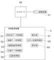
- FIG. FIG. 2 is a block diagram schematically showing the electrical configuration of the robot and state monitoring device
- Graph showing an example of current time-series data Graph showing the relationship between encoder temperature and grease temperature.
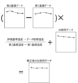
- FIG. 4 is a conceptual diagram for explaining correction performed on comparison data; Graph showing changes in I2 and temperature over time. Graph showing changes in I2 and temperature over time. 4 is a graph showing the transition of I2 after correction over time.
- FIG. 10 is a diagram showing an example of a screen displayed on the display unit for predicting the failure date based on the transition of I2 after correction; A graph for explaining a change in the prediction line for obtaining the failure prediction date linked to the number of reference days.
- FIG. 4 is a flowchart showing processing performed in the state monitoring device
- FIG. 2 is a block diagram schematically showing the electrical configuration of a condition monitoring device in a second embodiment
- FIG. 9 is a flowchart showing processing performed in the state monitoring device of the second embodiment
- FIG. 12 is a conceptual diagram illustrating processing performed on comparison data before correction in the fifth embodiment
- FIG. 12 is a conceptual diagram illustrating processing performed on comparison data before correction in the sixth embodiment
- FIG. 11 is a conceptual diagram for explaining the DTW method used in the seventh embodiment
- the graph which shows the temperature dependence of current time-series data regarding 8th Embodiment. 18 is a graph showing changes in motor speed corresponding to FIG. 17;
- FIG. 1 is a perspective view showing the configuration of the robot 1 according to the first embodiment of the present disclosure.
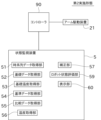
- FIG. 2 is a block diagram showing electrical configurations of the robot 1 and the state monitoring device 5. As shown in FIG.
- a state monitoring device 5 according to the present disclosure is applied to a robot (industrial robot) 1 as shown in FIG. 1, for example.
- the robot 1 performs operations such as painting, cleaning, welding, and transportation on the work to be worked.
- the robot 1 is implemented by, for example, a vertically articulated robot.
- the robot 1 includes a swivel base 10, an articulated arm 11, and a wrist portion 12.
- the swivel base 10 is fixed to the ground (for example, the floor of a factory).
- the articulated arm 11 has multiple joints.
- the wrist part 12 is attached to the tip of the articulated arm 11 .
- An end effector 13 is attached to the wrist portion 12 to work on a work to be worked.
- the robot 1 has an arm driving device 21.
- These drive devices are composed of, for example, an actuator configured as a servomotor, a reducer, and the like. However, the configuration of the driving device is not limited to the above.
- Each actuator is electrically connected to the controller 90 .
- the actuator operates to reflect command values input from the controller 90 .
- each servomotor that configures the arm drive device 21 is transmitted to each joint of the multi-joint arm 11, the swivel base 10, and the wrist portion 12 via a reduction gear.
- Each servomotor is attached with an unillustrated encoder for detecting its rotational position.
- the robot 1 works by reproducing the motions recorded by teaching.
- the controller 90 controls the actuators so that the robot 1 reproduces a series of actions taught in advance by the teacher.
- Teaching to the robot 1 can be performed by a teacher operating a teaching pendant (not shown).
- a program for moving the robot 1 is generated by teaching the robot 1.
- a program is generated each time the robot 1 is taught. If the operation to be taught to the robot 1 is different, the program is also different. By switching the program to be executed among a plurality of programs, the action to be performed by the robot 1 can be changed.
- the controller 90 is configured as a known computer including, for example, a CPU, ROM, RAM, auxiliary storage device, and the like.
- the auxiliary storage device is configured as, for example, an HDD, SSD, or the like.
- a program for moving the robot 1 and the like are stored in the auxiliary storage device.
- the state monitoring device 5 is connected to the controller 90 as shown in FIG.
- the state monitoring device 5 acquires, via the controller 90, changes such as the current value of the current flowing through the actuator (servomotor).
- this current value corresponds to a state signal reflecting the state of the robot 1 .
- the transition of the current value can be expressed by repeatedly acquiring the current value at short time intervals and arranging many current values in time series.
- the data obtained by arranging the values of the state signals in time series may be referred to as time series data.
- the state monitoring device 5 can determine whether there is an abnormality in the robot 1 by monitoring the acquired time-series data.
- the condition monitoring device 5 mainly targets the servo motors and speed reducers of the respective joints and determines whether or not there is an abnormality.
- abnormality includes a situation in which some kind of situation that is a sign of malfunction/impossibility does not occur in the servomotor, speed reducer, or bearing.
- the state monitoring device 5 includes a time-series data acquisition unit 51, a basic data acquisition unit (current-related basic data acquisition unit) 52, a basic temperature acquisition unit 53, and a comparison data acquisition unit (current-related A data acquisition unit 55 , a temperature acquisition unit 56 , a correction unit 57 , a robot state evaluation unit 59 , and a display unit 60 .
- the state monitoring device 5 is configured as a known computer including a CPU, ROM, RAM, auxiliary storage device, and the like.
- the auxiliary storage device is configured as, for example, an HDD, SSD, or the like.
- Programs for evaluating the state of the robot 1 and the like are stored in the auxiliary storage device.
- the computer can operate as a time-series data acquisition unit 51, a basic data acquisition unit 52, a basic temperature acquisition unit 53, a comparison data acquisition unit 55, a temperature acquisition unit 56, a correction unit 57, and a robot state. It can be operated as the evaluation unit 59, the display unit 60, and the like.
- the time-series data acquisition unit 51 acquires the time-series data described above.
- the time-series data acquisition unit 51 acquires time-series data for all servo motors included in the arm driving device 21 of the robot 1 .
- the time-series data is individually acquired for each of the plurality of servomotors (in other words, the plurality of speed reducers) arranged in each part of the robot 1 .
- the state signal is the current value.
- the current value means a measured value obtained by measuring the magnitude of the current flowing through the servomotor with a sensor.
- the sensor is provided in a servo driver (not shown) that controls the servo motor.
- a sensor may be provided for monitoring separately from the servo driver.
- a current command value given to the servomotor by the servo driver may be employed as the status signal.
- the servo driver feedback-controls the servo motor so that the current current value approaches the current command value. Therefore, for the purpose of detecting an abnormality in the servomotor or speed reducer, there is almost no difference between the current value and the current command value.
- the magnitude of the torque of the servo motor is proportional to the magnitude of the current. Therefore, a torque value or a torque command value may be used as the state signal.
- a deviation (rotational position deviation) between the target value for the rotational position of the servomotor and the actual rotational position obtained by the encoder may be used as the status signal.
- the servo driver gives a current command value obtained by multiplying this deviation by a gain to the servo motor. Therefore, the transition of the rotational position deviation shows a tendency similar to the transition of the current command value.
- the time-series data acquisition unit 51 acquires time-series data for each servo motor each time the robot 1 reproduces the instructed motion. However, instead of acquiring the time-series data for all reproduction operations, for example, it is possible to acquire only one or several reproduction operations per day.
- the time-series data acquisition unit 51 acquires time-series data of the current value flowing through each servomotor between the timing at which the acquisition start signal is received and the timing at which the acquisition end signal is received.
- the acquisition start signal and acquisition end signal are output by the controller 90, for example.
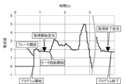
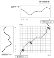
- the graph in FIG. 3 shows an example of current values flowing through the servo motors of certain joints when the robot 1 performs a regenerative motion. As shown in FIG. 3, the current value of the servomotor is zero before the reproduction operation program is executed. At this time, since an electromagnetic brake (not shown) operates at each joint, the attitude of the multi-joint arm 11 and the like is maintained.
- the program for the reproduction operation of the robot 1 is started.
- the brake is released, and almost at the same time, current begins to flow through the servomotor.
- the output shaft of the servomotor is controlled to stop.
- the rotation of the servomotor is started. Thereby, the motion of the robot 1 is substantially started.
- the controller 90 After the brake is released, the controller 90 outputs an acquisition start signal to the state monitoring device 5 (and thus the time-series data acquisition section 51) at a point shortly before the rotation of the servomotor starts.
- the controller 90 outputs an acquisition end signal to the time-series data acquisition section 51 after the servomotor stops rotating and before the program ends.
- the time-series data is a number of current values obtained by repeated detection at short, constant time intervals and arranged in chronological order. Therefore, current values in time-series data are sampled values.
- a time interval (sampling interval) for detecting the current value is, for example, several milliseconds.
- the sampling interval of the current value may match the control cycle of the robot 1 or may differ.
- the time-series data corresponds to the transition of the current value from the timing of the acquisition start signal to the timing of the acquisition end signal in the graph of FIG.
- the acquisition start signal or the acquisition end signal may be practically realized using other existing signals without preparing specially for measurement such as acquisition of time-series data.
- the falling edge of the "regeneration in progress" signal which is mainly used for safety purposes, can be used as the acquisition end signal.
- the time-series data acquisition unit 51 repeatedly acquires time-series data over a long period of time while the robot 1 is operating in a factory or the like.
- the basic data acquisition unit 52 obtains two pieces of basic data based on the time series data acquired by the time series data acquisition unit 51.
- the two basic data correspond to two different temperatures.
- the two basic data and the corresponding two different temperatures are the information on which the temperature compensation is based.
- Two basic data and two corresponding different temperatures are acquired for a period of time when the robot 1 is considered new and normal. This fixed period can also be called a learning period.
- the time when the robot 1 is regarded as new and normal typically means immediately after installation of the robot 1, but it may be after a trial run or break-in run for a while.
- the basic temperature acquisition unit 53 acquires temperatures corresponding to two pieces of basic data.
- the time-series data acquiring unit 51 obtains time-series data for a plurality of times by causing the robot 1 to perform the playback motion a plurality of times including the first time.
- the number of playback operations is arbitrary.
- the temperature at the time of acquisition of the time-series data is also acquired.
- the temperature can be detected, for example, by a temperature sensor (not shown) provided in the encoder described above.
- the no-load running torque which is the loss torque of the speed reducer
- this temperature can be considered the temperature of the grease, which is the lubricant inside the speed reducer.
- the speed reducer is usually located on the output shaft side of the motor, and the case of the motor and the case of the speed reducer are often in contact with each other.
- the temperature of the grease is affected by the temperature of the motor as well as the ambient air temperature.
- the encoder is located on the side opposite to the output shaft of the motor (the side opposite to the output shaft), and the case of the encoder is often in contact with the motor case.
- the temperature of the encoder is also affected by the temperature of the motor as well as the ambient air temperature.
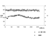
- FIG. 4 is a graph showing the result of verification of the relationship between the encoder temperature and the grease temperature by the inventor of the present application.
- the vertical axis indicates the temperature of the grease
- the horizontal axis indicates the temperature of the encoder.
- a durability test was conducted by having the robot repeatedly perform a certain operation.
- the graph shows two test results (diamond plot and square plot) when the robot repeatedly performed different actions. From the linear correlation between the two, the temperature of the grease can be estimated from the detected value of the encoder temperature. It is also possible to evaluate the encoder temperature as the grease temperature.
- the temperature sensor may be provided at a location different from the encoder.
- a room temperature sensor that measures the room temperature of the factory where the robot 1 operates can be used as the temperature sensor.
- a single room temperature sensor measurement value can be shared by a plurality of servo motors.
- the temperature detected by the temperature sensor is handled in units of 1°C, for example, by rounding down decimal places. It is not limited to this, and may be handled in units of 0.5° C., for example.
- time-series data Due to various factors such as time, weather, season, etc., temperature fluctuations occur when acquiring time-series data. For example, 60 playback operations including the first time yielded 60 time-series data, 5 of which were obtained when the temperature was 25°C, and another 5 were obtained when the temperature was 45°C. Consider the case where is obtained when .
- the 60 reproduction operations including the first time means the aforementioned learning period for temperature compensation.
- the basic data acquisition unit 52 of this embodiment acquires the first basic data by averaging five pieces of time-series data corresponding to a temperature of 25°C. Further, the basic data acquisition unit 52 obtains the second basic data by averaging the five pieces of time-series data corresponding to the temperature of 45°C. Each of the first basic data and the second basic data is time-series data of average values.
- the temperature at the time of acquiring the first basic data may be referred to as the first basic temperature
- the temperature at the time of acquiring the second basic data may be referred to as the second basic temperature.
- the basal temperature acquisition unit 53 acquires the first basal temperature (25° C.) and the second basal temperature (45° C.).
- the first basic data corresponds to the first current-related basic data
- the second basic data corresponds to the second current-related basic data
- the basic data acquisition unit 52 can also use one piece of time-series data as the first basic data as it is, instead of using time-series data of average values.
- the time-series data of current values contain many noise components. Therefore, it is preferable to use the average of a plurality of time-series data as the first basic data from the viewpoint of improving reliability.
- the second basic data is also preferably an average of a plurality of time-series data. In the above example, the average of five pieces of time-series data is obtained, but the number is not limited to five, and the number of pieces of time-series data is arbitrary as long as it is plural. From the viewpoint of reliability, the more time-series data to be averaged, the better.
- the first basal temperature and the second basal temperature are set so that the temperature difference between the two is not too small, and that a sufficient number of time-series data are obtained for both the first basal temperature and the second basal temperature. , as appropriate.
- a known filtering process may be performed on the first basic data and the second basic data.
- the comparison data acquisition unit 55 acquires comparison data.
- the time-series data that is the source of the first basic data and the second basic data is acquired only in the early stage, but the time-series data acquired in the initial stage and later is used as comparison data.
- the replay motions repeated by the robot 1 can be divided into 60 replay motions including the first replay motion and subsequent replay motions.
- the basic data acquisition unit 52 acquires the first basic data and the second basic data from the initial 60 time-series data.
- the comparison data acquisition unit 55 acquires comparison data from the initial 60 reproduction operations and subsequent reproduction operations.
- the time series data can be used as it is as the comparison data, or the time series data can be filtered and used as the comparison data.
- the basic data and comparison data are prepared for each reproduction operation of the robot 1 (in other words, for each program).
- the basic data and comparison data may be acquired for all the motions that have been taught, but for example, the main motion of the robot 1, or a simple motion that is not the main one but played back once a day. If there is an action to be performed, basic data and comparison data may be obtained only for this action.
- the temperature acquisition unit 56 acquires the temperature at the time of data acquisition when the comparison data acquisition unit 55 acquires comparison data.
- the temperature can be obtained in the same way as the basal temperature described above.
- the temperature at which the comparison data is acquired may be referred to as the data acquisition temperature.
- the filtering process performed on the basic data and the comparison data is performed, for example, to remove noise, etc. contained in the time-series data. Since the filtering process for data is well known, detailed description is omitted, but any filter such as a moving average filter, a CR circuit simulation filter, or the like can be used.
- the correction unit 57 corrects the influence of temperature change on the comparison data.
- a predetermined evaluation reference temperature is defined as a reference for data comparison. If the temperature at which the comparison data was acquired differs from the evaluation reference temperature, the correction unit 57 corrects the comparison data so that it corresponds to the data at the evaluation reference temperature.
- the first basic data, the first basic temperature, the second basic data, and the second basic temperature are used for this correction.
- the first basal temperature is 25°C
- the second basal temperature is 45°C
- the data acquisition temperature is 32°C
- the evaluation reference temperature is 30°C.
- the temperature ratio R2 is a ratio that indicates how close the data acquisition temperature is to the evaluation reference temperature. If the absolute value of the difference between the data acquisition temperature and the evaluation reference temperature is small, the temperature ratio R2 will be a value close to 0, and if the absolute value of the difference between the data acquisition temperature and the evaluation reference temperature is large, the temperature ratio R2 will range from 0 to 0. The values are separated in the positive or negative direction. In addition, the temperature ratio R2 indicates the magnitude relationship between the data acquisition temperature and the evaluation reference temperature. If the evaluation reference temperature is higher than the data acquisition temperature, R2 is positive, and if the evaluation reference temperature is lower than the data acquisition temperature, R2 is negative.
- the temperature ratio R2 is used to correct the comparison data. Therefore, the temperature ratio R2 can also be called a temperature ratio for correction.
- the correction unit 57 multiplies the difference obtained by subtracting the first basic data from the second basic data by the temperature ratio R2, and converts the obtained result into data for comparison. add to As described above, corrected comparison data is obtained.
- the post-correction comparison data means time-series data estimated assuming that it was acquired at the evaluation reference temperature instead of the data acquisition temperature. As described above, this correction is performed linearly in consideration of the difference between the temperature (data acquisition temperature) at the time of acquisition of the comparison data and the evaluation reference temperature.
- the robot state evaluation unit 59 evaluates the state of the robot 1 (each unit) based on the comparison data corrected by the correction unit 57 .
- the robot state evaluation unit 59 calculates statistics based on the corrected comparison data (time-series data).
- I2 is the root mean square value of the current.
- PTP is an abbreviation for Peak to Peak, and is a value obtained by subtracting a low peak current value from a high peak current value of a current waveform.
- PEAK is the larger of the absolute value of the maximum current and the absolute value of the minimum current. For example, if the current waveform has a maximum current value of +15A and a minimum current value of -12A, PEAK will be 15A. If the current waveform has a maximum current value of +11A and a minimum current value of -14A, PEAK will be 14A.
- FIG. 6 shows the transition of the value of I2 and the temperature transition in the first example for one of the servo motors provided in the robot 1 .
- FIG. 7 shows changes in the value of I2 and changes in temperature in the second example.
- the horizontal axis is time (specifically, elapsed days). The two data were acquired at the same time, and the temperature transitions are identical in the two graphs.
- the robot state evaluation unit 59 outputs the obtained statistics such as I2.
- the robot state evaluation unit 59 can plot statistics such as I2 over time and calculate a trend line indicating the trend. Since the trend line is well known, it will be briefly described.
- the trend line can be obtained as a straight line that approximates the point group plotted on the graph.
- the approximate straight line can be obtained by using the known method of least squares, but the method is not limited.
- the robot state evaluation unit 59 calculates the date and time when the trend line obtained as described above reaches a predetermined lifespan threshold.
- the robot state evaluation unit 59 can predict the remaining life of the servomotor or the like by calculating the period from the present to the date and time.
- the display unit 60 is configured as, for example, a liquid crystal display.
- the display unit 60 can display, for example, a variety of information such as a transition over time of a statistic such as I2 and a trend line.
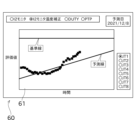
- the current value I2 monitor does not tend to increase due to deterioration, but in the example of the graph in FIG. 9, the current value I2 monitor increases due to deterioration.
- the scale in the direction of the vertical axis is set large in order to explain the changes in an easy-to-understand manner.
- FIG. 9 shows an example of output to the display unit 60 by the state monitoring device 5.
- the state monitoring device 5 predicts the future change of the evaluation value based on the past tendency of the evaluation value obtained based on the current value time-series data, and displays it on the display unit 60.
- the predicted failure date of the robot 1 is obtained based on the changing mode of .
- the condition monitoring device 5 can display a trend management screen as shown in FIG. Therefore, the condition monitoring device 5 also functions as a maintenance support device.
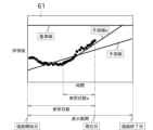
- the trend management screen includes a graph display section 61.
- the state monitoring device 5 can change the display mode of the graph displayed on the graph display unit 61 as shown in FIG.
- one end of the horizontal axis of the graph display portion 61 is the drawing start date
- the other end of the horizontal axis is the drawing end date.
- the period from the drawing start date to the drawing end date corresponds to the display period of the evaluation value, the prediction line, and the like.
- the drawing start date and drawing end date can be changed. For example, if the drawing start date is the first number of days before the current date and the drawing end date is the second number of days after the current date, the operator sets these first and second days independently. Can be changed. This allows the operator to grasp the evaluation value within the desired range.
- the post-correction comparison data is time-series data that is estimated when it is assumed to have been acquired at the evaluation reference temperature. Therefore, the influence of temperature change can be eliminated. As a result, the robot state evaluation unit 59 can more appropriately evaluate the state of the robot 1 .
- the evaluation reference temperature is determined to be a temperature different from the first basal temperature and the second basal temperature.
- the evaluation reference temperature may be equal to either the first basal temperature or the second basal temperature.
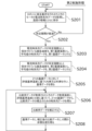
- the time-series data acquisition unit 51 of the state monitoring device 5 acquires current time-series data each time the robot 1 performs one reproduction operation, and stores the current time-series data together with information on the date and time of acquisition and temperature. (step S101).
- the state monitoring device 5 repeats the above process until a predetermined period of time elapses (step S102).
- the basal temperature acquisition unit 53 of the state monitoring device 5 acquires the lowest temperature at which, for example, five or more pieces of current time-series data are stored as the first basal temperature. Further, the basic data acquisition unit 52 obtains time series data of average values based on the plurality of current time series data acquired at the first basic temperature (step S103). The time-series data of this average value is the first basic data.
- the basal temperature acquisition unit 53 acquires, as the second basal temperature, the maximum temperature at which, for example, five or more pieces of current time-series data are stored.
- the basic data acquiring unit 52 obtains average time-series data based on the plurality of current time-series data acquired at the second basic temperature (step S104). The time-series data of this average value is the second basic data.
- Steps S101 to S104 are the preparatory process, that is, the learning period for temperature compensation. Next, the process of actually evaluating the state of the robot 1 is started.
- the comparison data acquisition unit 55 acquires time series data from the time series data acquisition unit 51 .
- This time-series data is comparison data.
- the temperature obtaining unit 56 obtains the temperature when the comparison data is obtained. This temperature is the data acquisition temperature.
- the correction unit 57 calculates the above temperature ratio R2 based on the difference between the evaluation reference temperature and the data acquisition temperature.
- the correction unit 57 multiplies the difference obtained by subtracting the first basic data from the second basic data by the temperature ratio R2.
- time-series data for correcting the comparison data can be obtained (step S105).
- the correction unit 57 corrects the comparison data by adding the time-series data to the comparison data (step S106).
- the robot state evaluation unit 59 calculates statistics such as I2 for the comparison data corrected in step S106, and outputs them to the display unit 60 (step S107).
- the state monitoring device 5 of this embodiment monitors the state of the robot 1 that can reproduce predetermined actions.
- the condition monitoring device 5 includes a basic data acquisition unit 52 , a basic temperature acquisition unit 53 , a comparison data acquisition unit 55 , a temperature acquisition unit 56 , a correction unit 57 and a robot condition evaluation unit 59 .
- the basic data acquisition unit 52 acquires first basic data, which is current data, and second basic data, which is current data, regarding the current of the motor that drives the robot 1 .
- the basal temperature acquisition unit 53 acquires a first basal temperature, which is the temperature when the first basic data is obtained, and a second basal temperature, which is the temperature when the second basic data is obtained.
- the comparison data acquisition unit 55 acquires comparison data, which is current data, regarding the current of the motor.
- the temperature acquisition unit 56 acquires the data acquisition temperature, which is the temperature at the time of acquisition of the comparison data.
- the correction unit 57 corrects the comparison data based on the first basic data, the second basic data, the first basic temperature, the second basic temperature, and the data acquisition temperature.
- the robot state evaluation unit 59 evaluates the state of the robot 1 using the corrected comparison data.
- the robot state evaluation unit 59 calculates I2, the maximum current value, the minimum current value, PTP, or PEAK based on the corrected comparison data, and the calculation result The state of the robot is evaluated based on
- the first basic data, the second basic data, and the comparison data are current time-series data.
- the correction unit 57 corrects the comparison data so that it corresponds to the data at the predetermined evaluation reference temperature.
- the correction unit 57 linearly corrects the current-related data.
- each of the first basic data and the second basic data is average value time-series data based on a plurality of time-series data.
- the condition monitoring device 5 includes a reference data acquisition unit 54 in addition to the configuration of the first embodiment.
- the reference data acquisition unit 54 obtains reference data based on the two pieces of basic data obtained by the basic data acquisition unit 52.
- Reference data means time-series data corresponding to the above-mentioned evaluation reference temperature. Specifically, the reference data is obtained by estimating the time-series data at the evaluation reference temperature by interpolation or extrapolation based on the first basic data and the second basic data.
- the evaluation reference temperature is 30°C.
- the first basal temperature is 25°C
- the second basal temperature is 45°C
- the temperature ratio R1 is a ratio that indicates how close the evaluation reference temperature is to the first basal temperature. If the evaluation reference temperature is close to the first basic temperature, the temperature ratio R1 will be close to 0, and if the evaluation reference temperature is close to the second basic temperature, the temperature ratio R1 will be close to 1.
- the reference data acquisition unit 54 multiplies the difference obtained by subtracting the first basic data from the second basic data by the temperature ratio R1, and adds the obtained result to the first basic data. As described above, the reference data is obtained.
- the first basic data and the second basic data are plotted in this multidimensional space.
- the reference data corresponds to a point obtained by internally dividing a line segment connecting a point of the first basic data and a point of the second basic data in the multidimensional space.
- the internal division ratio at this time is determined based on a ratio indicating how close the evaluation reference temperature is to the first and second basal temperatures.
- reference data is obtained by externally dividing the line segment connecting the points of the two basic data, instead of internally dividing it.
- reference data can also be obtained by extrapolation.
- the reference data obtained as described above means time-series data estimated when it is assumed that it is obtained at the evaluation reference temperature, not at the first basal temperature or the second basal temperature.
- the basic data and reference data are prepared for each reproduction operation of the robot 1 (in other words, for each program). Although basic data and reference data may be acquired for all taught actions, for example, a main action to be performed by the robot 1, or a simple non-main action that is reproduced once a day. Basic data and reference data may be acquired only for the movement of the body, if any.
- the robot state evaluation unit 59 calculates the Euclidean distance (dissimilarity) indicating the magnitude of the difference between the corrected comparison data and the reference data.
- the robot state evaluation unit 59 outputs the obtained Euclidean distance as an evaluation amount.
- the Euclidean distance D between the time-series data a and the time-series data b is represented by the following formula (1), where m is the length (number of elements) of the time-series data.
- the robot state evaluation unit 59 uses the Euclidean distance calculated as described above to evaluate the state of the robot 1 (each unit). Specifically, the robot state evaluation unit 59 uses each Euclidean distance obtained for each servo motor to evaluate the state of the servo motor.
- the Euclidean distance can be considered as a numerical representation of the degree of this divergence.
- the robot state evaluation unit 59 uses the Euclidean distance to determine whether or not there is an abnormality in each of the servomotors of the six joints. Further, based on the transition of the Euclidean distance with the passage of time up to the present, it is possible to predict the timing at which the servo motor will malfunction/be disabled in the future.
- the robot state evaluation unit 59 can calculate a trend line that indicates the tendency of the Euclidean distance over time.
- the robot state evaluation unit 59 calculates the date and time when the trend line obtained as described above reaches a predetermined life threshold.
- the robot state evaluation unit 59 can predict the remaining life of the servomotor or the like by calculating the period from the present to the date and time.
- the display unit 60 is configured as, for example, a liquid crystal display.
- the display unit 60 can display, for example, various information such as the transition of the Euclidean distance over time and trend lines.
- the reference data is time-series data that is estimated when it is assumed to have been acquired at the evaluation reference temperature. The same applies to the corrected comparison data. Therefore, the effect of temperature change can be removed when calculating the dissimilarity. As a result, the robot state evaluation unit 59 can more appropriately evaluate the state of the robot 1 .
- the evaluation reference temperature is determined to be a temperature different from the first basal temperature and the second basal temperature.
- the evaluation reference temperature may be equal to either the first basal temperature or the second basal temperature.
- the value of the above-mentioned temperature ratio R1 becomes 0 or 1, so the calculation becomes simple.
- Steps S201 to S204 in FIG. 13 are the same as steps S101 to S104 in FIG. 11, respectively, so description thereof will be omitted.
- step S205 the process of step S205 is performed after step S204 and before step S206.
- the reference data acquisition unit 54 interpolates or extrapolates the first basic data and the second basic data based on the aforementioned evaluation reference temperature to obtain time-series data. This time-series data is reference data.
- Steps S206 and S207 in FIG. 13 are the same as steps S105 and S106 in FIG. 11, respectively, so description thereof will be omitted.
- step S208 the robot state evaluation unit 59 obtains the degree of dissimilarity between the reference data obtained in step S205 and the comparison data corrected in step S207.
- the obtained dissimilarity is output to the display unit 60 .
- reference data to be compared with the comparison data is obtained based on the first basic data and the second basic data.
- the robot state evaluation unit 59 obtains the degree of dissimilarity between the comparison data and the reference data.
- the robot state evaluation unit 59 obtains the Euclidean distance between the comparison data and the reference data as the degree of dissimilarity.
- the correction unit 57 adds (evaluation reference temperature ⁇ data acquisition temperature)/(second basic temperature ⁇ second 1 basal temperature) is added to the comparison data to perform linear correction.
- the corrected comparison data is used to calculate statistics such as I2, and the state of the robot 1 is evaluated based on these statistics.
- reference data is created, and the similarity between the reference data and the corrected comparison data is focused on. is being evaluated.
- any of the above evaluation methods can be applied, with some exceptions.
- dissimilarity such as the Euclidean distance between the reference data and the comparison data, in addition to the evaluation with statistics. It means that you can also evaluate
- the current ratio obtained from the temperature ratio is used. Interpolate or extrapolate.
- the reference data can be obtained.
- the correction unit 57 multiplies the difference obtained by subtracting the first basic data from the second basic data by f (evaluation reference temperature - data acquisition temperature) / f (second basic temperature - first basic temperature). is added to the current-related data to perform linear correction.
- the correction unit 57 corrects the comparison data by a method different from that of the above embodiments.
- the first basic data and the second basic data which are current time-series data, are obtained at different temperatures. If there is a difference in current value between the first basic data and the second basic data, this difference in current value is the combination of the dry friction torque variation and the no-load running torque variation. Equivalent to.
- Dry friction torque refers to loss torque when the number of revolutions of the motor is near zero, and means loss torque due to known dry friction. However, the torque when the number of revolutions of the motor is near zero is considered to include loss torque other than dry friction torque, such as hysteresis loss.
- the no-load running torque means loss torque due to the viscosity of the lubricant when the motor is rotated without load.
- the current value corresponding to the sum of the dry friction torque and the no-load running torque may be referred to as the loss torque current value.
- the loss torque current value has the property of increasing by 1/A each time the temperature increases by a predetermined unit temperature tU .
- A is a number larger than one. Any combination of values of A and t U can be determined. For example, when t U is 10° C., the value of A can be set to 1.1 or more and 1.6 or less, depending on the type of speed reducer. For example, the value of A may be changed between the high temperature range and the low temperature range.
- the loss torque current value I lt,tp1 at the first basic temperature is obtained by using the current value of the first basic data as I 1 , the current value of the second basic data as I 2 , and the first basic temperature as tp 1 .
- I lt,tp1 (I 1 -I 2 )/(1-A ⁇ ((tp 1 -tp 2 )/t U ))
- the loss torque current value Ilt,tpX at the data acquisition temperature tpX can be expressed by the following equation.
- I lt,tpX I lt,tp1 ⁇ A ⁇ ((tp 1 -tp X )/t U )
- the loss torque current value Ilt,tpS at the evaluation reference temperature tpS can be expressed by the following equation.
- I lt,tpS I lt,tp1 ⁇ A ⁇ ((tp 1 -tp S )/t U )
- the comparison data I COMP corrected to correspond to the evaluation reference temperature tp S can be obtained.
- I COMP I ORIG -I lt,tpX +I lt,tnS
- the first basic data, the second basic data, and the current-related data are current time-series data.
- the correction unit 57 corrects the comparison data with respect to the temperature characteristic of the loss torque of the motor.
- the correction unit 57 increases the current value corresponding to the loss torque by 1/A each time the temperature increases by a predetermined unit temperature tU , where A is a number greater than 1. Compensation is performed on the comparison data using the following relationship.
- A is 1.1 or more and 1.6 or less when the unit temperature t U is 10°C.
- the correction unit 57 can also correct the comparison data so as to cancel the current corresponding to the loss torque of the motor.
- the current corresponding to the loss torque of the motor can be removed from the current time series data. Therefore, the evaluation becomes simpler, which may be advantageous for evaluating the state of the robot 1 .
- the robot state evaluation unit 59 moves relatively in the time axis direction in order to match the phase of the comparison data with the reference data (comparison target data). The difference is that the processing to cause
- the robot state evaluation unit 59 of the present embodiment performs a process of moving the waveform of the comparison data in multiple steps in the time axis direction.
- the robot state evaluation unit 59 acquires the Euclidean distance (dissimilarity) between the comparison data and the reference data for each stage by calculation.
- FIG. 14 shows an example in which the comparison data is moved by two steps, one step in the negative direction of the time axis and one step in the positive direction.
- the Euclidean distance is calculated for three stages including no movement. Both the amount of movement in the direction of the time axis per stage and the number of stages of movement can be determined arbitrarily.
- this waveform shift uniformly shifts the correspondence between the m current values included in the reference data and the m current values included in the comparison data. can be practically realized.
- the robot state evaluation unit 59 obtains the minimum Euclidean distance.
- the minimum value of this Euclidean distance is used as an evaluation value.
- the robot state evaluation unit 59 moves at least one of the waveform of the reference data and the waveform of the comparison data in the time axis direction in a plurality of stages. while obtaining the dissimilarity between the two waveforms. With the comparison data moved so that the dissimilarity between the two waveforms is minimized, the robot state evaluation unit 59 obtains the dissimilarity between the reference data and the comparison data.
- the correction unit 57 corrects the i-th current value among the m current values included in the reference data and the i ⁇ p-th to i+p-th current values among the m current values included in the comparison data. Calculate the difference between the current value of and , respectively.
- the correction unit 57 checks which of the i ⁇ pth to i+pth current values of the comparison data is closest to the ith current value of the reference data.
- the i ⁇ 1th has the smallest absolute value of difference with respect to the ith current value of the reference data.
- the difference is -0.2.
- the correction unit 57 corrects the i-th current value of the comparison data so that it becomes the (i-1)-th current value with the minimum absolute value of the difference.
- the correction unit 57 repeats the above processing for all m current values of the reference data.
- the comparison data can be moved in the direction of the time axis to some extent and expanded or contracted in the direction of the time axis to some extent so as to increase the degree of similarity to the reference data.
- the robot state evaluation unit 59 obtains the Euclidean distance between the reference data and the corrected comparison data as the degree of dissimilarity. This enables appropriate evaluation.
- reference data to be compared with the comparison data is obtained based on at least one of the first basic data and the second basic data.
- the robot state evaluation unit 59 selects the closest sampled value to the i-th sampled value of the waveform of the reference data among the i ⁇ p-th to i+p-th sampled values (where i and p are integers equal to or greater than 1) of the comparison data. Modify the i-th sampled value of the comparison data with the sampled value.
- the robot state evaluation unit 59 obtains the degree of dissimilarity between the corrected comparison data and the reference data.
- the condition monitoring device 5 of this embodiment includes a reference data acquisition unit 54, as in the second embodiment described above.
- the robot state evaluation unit 59 uses the DTW distance is obtained and used as an evaluation value.
- DTW is an abbreviation for Dynamic Time Warping.
- the DTW method is used to calculate the degree of similarity between two time series data.
- a major feature of the DTW method is that it allows non-linear expansion and contraction of time-series data in the direction of the time axis when calculating the degree of similarity. As a result, the DTW method can obtain a result close to human intuition regarding the degree of similarity of time-series data.
- the robot state evaluation unit 59 calculates the DTW distance (dissimilarity) indicating the magnitude of the difference between the comparison data and the reference data, and outputs this value as an evaluation value.
- a plurality (s) of current values included in the reference data are arranged in chronological order along a first axis extending in the horizontal direction.
- a plurality (p) of current values included in the comparison data are arranged in chronological order along the second axis extending in the vertical direction.
- Each cell (c, d) represents correspondence between the c-th current value in the reference data and the d-th current value in the comparison data. However, 1 ⁇ c ⁇ d.
- Each cell (c, d) is associated with a numerical value representing the difference between the c-th current value in the reference data and the d-th current value in the comparison data.
- the absolute value of the difference between the c-th current value and the d-th current value is stored in association with each cell.
- the robot state evaluation unit 59 obtains a warping path from the starting point cell located in the lower left corner of the matrix in FIG. 16 to the ending point cell located in the upper right corner.
- the starting point cell (1, 1) is the current value at the earliest timing (that is, the first) in the time series among the s current values in the reference data, and the p current values in the comparison data, This corresponds to associating the earliest timing (that is, the first) current value in the time series.
- the end point cell (s, p) is the current value at the last timing (that is, the sth) in the time series among the s current values in the reference data, and the current value in the p current values in the comparison data. This corresponds to associating the last timing (that is, the p-th) current value in the sequence.
- a route starting from the starting point cell and reaching the ending point cell is considered according to the following rules [1] and [2]. [1] You can only move to adjacent cells vertically, horizontally, or diagonally. [2] The reference data cannot be moved back in time, and the comparison data cannot be moved back in time either.
- a series of such cells is called a route or warping path.
- a warping path indicates how s current values in the reference data are associated with p current values in the comparison data. From another point of view, the warping path represents how the two pieces of time-series data are expanded or contracted along the time axis.
- the robot state evaluation unit 59 calculates the sum of numerical values (in this embodiment, the absolute value of the difference between the c-th current value and the d-th current value) that represent the differences associated with the passing cells in the possible warping paths. Find the warping path that minimizes . In the following, this warping pass may be called an optimal warping pass. Also, the total value of the values in each square in this optimal warping path is sometimes called the DTW distance. The robot state evaluation unit 59 obtains this DTW distance.
- the DTW distance average value By dividing the DTW distance by the number of squares passed through, the DTW distance average value can be obtained.
- the DTW distance average value may be obtained by dividing the DTW distance by the number of elements s or p of any time-series data. Instead of the DTW distance, the DTW distance average value can also be used as the evaluation value.
- the robot state evaluation unit 59 of this embodiment obtains an optimum warping path using a DP matching technique (dynamic programming).
- DP is an abbreviation for Dynamic Programming. Since the DP matching method is well known, the explanation is omitted.
- reference data to be compared with the comparison data is obtained based on at least one of the first basic data and the second basic data.
- the robot state evaluation unit 59 obtains the DTW distance between the comparison data and the reference data as the degree of dissimilarity.
- the first basic data, the second basic data, and the comparison data are all time-series data of current values, and statistics are calculated from the comparison data.
- the first basic data, the second basic data, and the comparison data are data obtained by statistically appropriately processing the time-series data of current values.
- I2 maximum current value
- minimum current value PTP, and PEAK
- the first basic data, second basic data, and comparison data are simple scalar quantities. Therefore, calculations for interpolation or extrapolation are simplified when calculating the reference data and when correcting the comparison data.
- the first current-related basic data, the second current-related basic data, and the current-related data are I2, the maximum current value, the minimum current value, PTP , or PEAK.
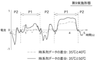
- the graph in FIG. 17 shows the current waveform obtained by subtracting the current waveform at 40° C. from the current waveform at 35° C., and the current waveform obtained by subtracting the current waveform at 50° C. from the current waveform at 35° C. for one of the servo motors provided in the robot 1. something is shown.
- the vertical axis of the graph is current value, and the horizontal axis is time (specifically, seconds). Since the two differential waveforms are clearly different, it can be seen that the current waveform has temperature dependence.
- the graph in FIG. 18 shows changes in the speed of the servomotor when the robot 1 is caused to perform a regenerative operation with the current waveform corresponding to FIG.
- the vertical axis of the graph is speed
- the horizontal axis is time (specifically, seconds).
- the time on the horizontal axis of FIG. 18 corresponds to the time on the horizontal axis of FIG.
- the period during which the robot 1 performs the regenerative operation with the current waveform that is the basis of the differential waveform in FIG. is included.
- the first period P1 indicated by the white arrow is the period during which the rotation of the motor is substantially zero.
- the current value in this first period P1 is considered to correspond to the dry friction torque.
- a second period P2 without an arrow is a period during which the rotation of the motor does not become substantially zero.
- the current value in this second period P2 is considered to correspond to the no-load running torque.
- the correction unit 57 can correct the comparison data only for one of the first period P1 and the second period P2 shown in FIG. Further, for example, for the first period P1, the simple linear correction as shown in the first embodiment is performed on the comparison data, while for the second period P2, the temperature increases by a predetermined unit temperature tU .
- the comparison data can be corrected by using the property of 1/A times each time. Alternatively, simple linear correction may be performed for both periods, and correction may be made from the basic data divided into the respective periods. Furthermore, using the property that the temperature increases by 1/A each time the temperature increases by a predetermined unit temperature t U in both periods, the comparison data can be corrected with a different value of A for each period.
- the time-series data of the current value is divided into a period in which the rotation of the motor is substantially zero and a period in which it is not, and the correction method or parameters performed by the correction unit 57 are different for each period.
- corrections are made to only one of the two. This makes it possible to more effectively remove the influence of temperature change.
- the correction unit 57 sets the comparison data to the first period P1 in which the motor rotation speed is substantially zero and the period P1 in which the motor rotation speed is substantially zero. and a second period P2 which is essentially non-zero, only one of the first period P1 and the second period P2 is corrected. Alternatively, different corrections are performed between the first period P1 and the second period P2.
- the state monitoring device 5 does not have to be directly connected to the robot 1, and may acquire time-series data reflecting the state of the robot 1 from the controller 90 of the robot 1, for example, via a communication line such as the Internet.
- the controller 90 acquires and stores the current value in real time during the reproduction operation, and by batch processing or the like, outputs the program number, the date and time of acquisition of the current value, the information identifying the servomotor, and the time-series data of the current value. It is transmitted collectively to the state monitoring device 5 .
- the state monitoring device 5 may be incorporated in the controller 90 instead of being provided separately from the controller 90 .
- the state monitoring device 5 may be realized by using the computer of the controller 90 of the robot 1 without providing the computer functioning as the CPU, ROM, RAM, auxiliary storage device, etc. of the state monitoring device 5 .
- each element including the condition monitoring device 5 disclosed above are general-purpose processors, dedicated processors, integrated circuits, ASICs (Application Specific Integrated Circuits) configured or programmed to perform the disclosed functions, It can be implemented using circuitry or processing circuitry including conventional circuitry and/or combinations thereof.
- a processor is considered a processing circuit or circuit because it includes transistors and other circuits.
- a circuit, unit, or means is hardware that performs or is programmed to perform the recited functions.
- the hardware may be the hardware disclosed herein, or other known hardware programmed or configured to perform the recited functions.
- a circuit, means or unit is a combination of hardware and software, where the hardware is a processor which is considered a type of circuit, the software being used to configure the hardware and/or the processor.
- a state monitoring device for monitoring the state of an industrial robot capable of reproducing a predetermined motion First current-related basic data, which is at least one current data or statistical data of the current data, and first current-related basic data, which is at least one current data or statistical data of the current data, regarding the current of the motor that drives the industrial robot.
- a current-related basic data acquisition unit for acquiring current-related basic data
- a basal temperature acquisition unit that acquires a first basal temperature, which is the temperature at the time of acquiring the first current-related basic data, and a second basal temperature, which is the temperature at the time of acquiring the second current-related basic data
- a current-related data acquiring unit for acquiring at least one piece of current data or current-related data, which is statistical data of the current data, regarding the current of the motor
- a temperature acquisition unit that acquires a data acquisition temperature that is the temperature at the time of acquisition of the current-related data
- a correction unit that corrects the current-related data based on the first current-related basic data, the second current-related basic data, the first basic temperature, the second basic temperature, and the data acquisition temperature
- a robot state evaluation unit that evaluates the state of the robot using the corrected current-related data
- a condition monitoring device comprising:
- (Item 2) The condition monitoring device according to item 1,
- the robot state evaluation unit based on the corrected current-related data, the root mean square of the current, maximum current, the minimum value of the current, A value obtained by subtracting the current value of the low peak from the current value of the high peak of the current waveform, or the absolute value of the maximum current or the absolute value of the minimum current, whichever is greater; is calculated, and the state of the robot is evaluated based on the calculation result.
- Comparison target data to be compared with the current-related data is obtained based on at least one of the first current-related basic data and the second current-related basic data, The state monitoring device, wherein the robot state evaluation unit obtains a degree of dissimilarity between the current-related data and the comparison target data.
- the condition monitoring device (Item 4) The condition monitoring device according to item 1, The robot state evaluation unit obtains a Euclidean distance between the current-related data and the comparison target data as the degree of dissimilarity.
- the condition monitoring device (Item 5) The condition monitoring device according to item 3 or 4, The robot state evaluation unit obtains a degree of dissimilarity between the current-related data and the comparison target data while moving the current-related data relative to the comparison target data in a plurality of steps in a time axis direction. , In a state in which the current-related data is relatively moved so that the dissimilarity becomes a minimum value, the robot state evaluation unit obtains the dissimilarity between the current-related data and the comparison target data. surveillance equipment.
- the condition monitoring device (Item 6) The condition monitoring device according to item 3, The robot state evaluation unit obtains a DTW distance between the current-related data and the comparison target data as the degree of dissimilarity.
- the condition monitoring device (Item 8) The condition monitoring device according to item 1,
- the first current-related basic data, the second current-related basic data, and the current-related data are the root mean square of the current, maximum current, the minimum value of the current, A value obtained by subtracting the current value of the low peak from the current value of the high peak of the current waveform, or A condition monitoring device that is the larger of the absolute value of the maximum current and the absolute value of the minimum current.
- the condition monitoring device according to any one of items 1 to 7 or item 9,
- the correction unit adds (said evaluation reference temperature - said data acquisition temperature) / ( said second basic temperature - said first 1 basal temperature) is added to the current-related data to perform linear correction.
- f the evaluation reference temperature - the data acquisition temperature
- f the second basal temperature - the first basal temperature
- the condition monitoring device according to any one of items 1 to 7 or any one of items 9 to 11,
- the first current-related basic data, the second current-related basic data, and the current-related data are current time-series data
- the correction unit corrects the current-related data so that it corresponds to data at a predetermined evaluation reference temperature, corrects the temperature characteristics of the loss torque of the motor, or cancels the current corresponding to the loss torque of the motor.
- the condition monitoring device according to any one of items 1 to 7 or any one of items 9 to 12,
- the correction unit calculates the current-related A condition monitoring device that corrects data.
- the condition monitoring device according to any one of items 1 to 7 or any one of items 9 to 12,
- the correction unit divides the time-series data of the current-related data into a first period in which the number of rotations of the motor is substantially zero and a second period in which the number of rotations of the motor is not substantially zero. different corrections for the first period and the second period, respectively.
- a state monitoring method for monitoring the state of an industrial robot capable of reproducing a predetermined motion First current-related basic data, which is at least one current data or statistical data of the current data, and first current-related basic data, which is at least one current data or statistical data of the current data, regarding the current of the motor that drives the industrial robot.
- Acquire current-related basic data Acquiring a first basic temperature, which is the temperature at the time of acquiring the first current-related basic data, and a second basic temperature, which is the temperature at the time of acquiring the second current-related basic data, obtaining at least one current data or current-related data, which is statistical data of the current data, for the current of the motor; Acquiring a data acquisition temperature, which is the temperature at the time of acquisition of the current-related data; correcting the current-related data based on the first current-related basic data, the second current-related basic data, the first basic temperature, the second basic temperature, and the data acquisition temperature; A state monitoring method, wherein the corrected current-related data is used for robot state evaluation.
Landscapes
- Engineering & Computer Science (AREA)
- Robotics (AREA)
- Mechanical Engineering (AREA)
- Manipulator (AREA)
- Numerical Control (AREA)
Abstract
A current-related basis data acquisition unit acquires first current-related basis data and second current-related basis data pertaining to the current of a motor for driving a robot. A basis temperature acquisition unit acquires a first basis temperature and a second basis temperature that are in effect during the aforementioned acquisition of data. A current-related data acquisition unit acquires current-related data pertaining to the current of the motor. A temperature acquisition unit acquires a data acquisition temperature that is in effect during the aforementioned acquisition of data. On the basis of the first current-related basis data, the second current-related basis data, the first basis temperature, the second basis temperature, and the data acquisition temperature, a correction unit corrects the current-related data so as to correspond to a prescribed evaluation reference temperature. A robot state evaluation unit evaluates the state of the robot using the corrected current-related data.
Description
本開示は、主として、ロボットの状態を監視し、ロボットのメンテナンスを支援する状態監視装置に関する。
The present disclosure mainly relates to a state monitoring device that monitors the state of a robot and supports maintenance of the robot.
産業用ロボットを工場等で反復的に稼動させると、ロボットの各部(例えば、機械部品)が劣化していくことが避けられない。状況が進行すると、やがてロボットが故障する。ロボットが故障してラインが長期間停止した場合、大きな損失となることから、ロボットの故障発生前にメンテナンス(保全)を実施することが強く求められている。一方で、メンテナンスを頻繁に行うことも、メンテナンス費用等の観点から困難である。
When industrial robots are operated repeatedly in factories, etc., it is inevitable that each part of the robot (for example, mechanical parts) will deteriorate. As the situation progresses, the robot eventually breaks down. If a robot breaks down and the line stops for a long period of time, it will result in a large loss, so there is a strong demand to perform maintenance before the robot breaks down. On the other hand, frequent maintenance is also difficult from the viewpoint of maintenance costs and the like.
特許文献1は、ロボットコントローラを開示する。特許文献1の構成においては、ロボットコントローラ内のデータを外部に保存し、解析用装置で解析することができる。
Patent Document 1 discloses a robot controller. In the configuration of Patent Literature 1, data in the robot controller can be saved externally and analyzed by an analysis device.
特許文献1において解析されるロボットのデータには、温度による影響を受けるデータが含まれている場合がある。しかし、特許文献1では、温度変化のデータに対する影響を抑制する方法について何ら記載されていない。
The robot data analyzed in Patent Document 1 may include data that is affected by temperature. However, Patent Literature 1 does not describe at all how to suppress the influence of temperature change on data.
本開示は以上の事情に鑑みてされたものであり、その主な目的は、温度変化の影響を効果的に抑制して、ロボットの故障の予兆を良好に捉えることにある。
The present disclosure has been made in view of the above circumstances, and its main purpose is to effectively suppress the effects of temperature changes and to better detect signs of robot failure.
本開示の解決しようとする課題は以上の如くであり、次にこの課題を解決するための手段とその効果を説明する。
The problem to be solved by the present disclosure is as described above. Next, the means for solving this problem and its effect will be explained.
本開示の第1の観点によれば、以下の構成の状態監視装置が提供される。即ち、この状態監視装置は、予め決められた動作を再生可能な産業用ロボットの状態を監視する。状態監視装置は、電流関連基礎データ取得部と、基礎温度取得部と、電流関連データ取得部と、温度取得部と、補正部と、ロボット状態評価部と、を備える。前記電流関連基礎データ取得部は、前記産業用ロボットを駆動するモータの電流について、少なくとも1つの電流データ又は前記電流データの統計データである第1電流関連基礎データ、及び、少なくとも1つの電流データ又は前記電流データの統計データである第2電流関連基礎データを取得する。前記基礎温度取得部は、前記第1電流関連基礎データの取得時における温度である第1基礎温度、及び、前記第2電流関連基礎データの取得時における温度である第2基礎温度を取得する。前記電流関連データ取得部は、前記モータの電流について、少なくとも1つの電流データ又は前記電流データの統計データである電流関連データを取得する。前記温度取得部は、前記電流関連データの取得時における温度であるデータ取得温度を取得する。前記補正部は、前記第1電流関連基礎データ、前記第2電流関連基礎データ、前記第1基礎温度、前記第2基礎温度、及び前記データ取得温度に基づいて、前記電流関連データに対して補正を行う。前記ロボット状態評価部は、補正後の前記電流関連データを用いてロボットの状態評価を行う。
According to the first aspect of the present disclosure, a state monitoring device having the following configuration is provided. That is, this state monitoring device monitors the state of an industrial robot capable of reproducing a predetermined motion. The state monitoring device includes a current-related basic data acquisition section, a basic temperature acquisition section, a current-related data acquisition section, a temperature acquisition section, a correction section, and a robot state evaluation section. The current-related basic data acquisition unit obtains at least one current data or first current-related basic data, which is statistical data of the current data, and at least one current data or Second current-related basic data, which is statistical data of the current data, is acquired. The basal temperature acquisition unit acquires a first basal temperature, which is the temperature when the first current-related basic data is obtained, and a second basal temperature, which is the temperature when the second current-related basic data is obtained. The current-related data acquisition unit acquires current-related data, which is at least one piece of current data or statistical data of the current data, regarding the current of the motor. The temperature acquisition unit acquires a data acquisition temperature, which is the temperature at the time of acquisition of the current-related data. The correction unit corrects the current-related data based on the first current-related basic data, the second current-related basic data, the first basic temperature, the second basic temperature, and the data acquisition temperature. I do. The robot state evaluation unit evaluates the state of the robot using the corrected current-related data.
本開示の第2の観点によれば、以下の状態監視方法が提供される。即ち、この状態監視方法では、予め決められた動作を再生可能な産業用ロボットの状態を監視する。前記産業用ロボットを駆動するモータの電流について、少なくとも1つの電流データ又は前記電流データの統計データである第1電流関連基礎データ、及び、少なくとも1つの電流データ又は前記電流データの統計データである第2電流関連基礎データを取得する。前記第1電流関連基礎データの取得時における温度である第1基礎温度、及び、前記第2電流関連基礎データの取得時における温度である第2基礎温度を取得する。前記モータの電流について、少なくとも1つの電流データ又は前記電流データの統計データである電流関連データを取得する。前記電流関連データの取得時における温度であるデータ取得温度を取得する。前記第1電流関連基礎データ、前記第2電流関連基礎データ、前記第1基礎温度、前記第2基礎温度、及び前記データ取得温度に基づいて、前記電流関連データに対して補正を行う。補正後の前記電流関連データをロボットの状態評価のために使用する。
According to the second aspect of the present disclosure, the following state monitoring method is provided. That is, in this state monitoring method, the state of an industrial robot capable of reproducing a predetermined motion is monitored. First current-related basic data, which is at least one current data or statistical data of the current data, and first current-related basic data, which is at least one current data or statistical data of the current data, regarding the current of the motor that drives the industrial robot. 2 Acquire current-related basic data. A first basic temperature, which is the temperature when the first current-related basic data is acquired, and a second basic temperature, which is the temperature when the second current-related basic data is acquired, are acquired. At least one piece of current data or current-related data, which is statistical data of the current data, is obtained for the current of the motor. A data acquisition temperature, which is the temperature at which the current-related data is acquired, is acquired. The current-related data is corrected based on the first current-related basic data, the second current-related basic data, the first basic temperature, the second basic temperature, and the data acquisition temperature. The corrected current-related data are used for evaluating the state of the robot.
これにより、温度変化の影響を補正によって抑制しつつ、ロボットの状態を評価することができる。従って、ロボットの故障の予兆を良好に発見することができる。
This makes it possible to evaluate the state of the robot while suppressing the effects of temperature changes through correction. Therefore, it is possible to find a good sign of failure of the robot.
本開示によれば、温度変化の影響を効果的に抑制して、ロボットの故障の予兆を良好に捉えることができる。
According to the present disclosure, it is possible to effectively suppress the effects of temperature changes and to better detect signs of robot failure.
次に、図面を参照して、開示される実施の形態を説明する。図1は、本開示の第1実施形態に係るロボット1の構成を示す斜視図である。図2は、ロボット1及び状態監視装置5の電気的な構成を示すブロック図である。
Next, the disclosed embodiments will be described with reference to the drawings. FIG. 1 is a perspective view showing the configuration of the robot 1 according to the first embodiment of the present disclosure. FIG. 2 is a block diagram showing electrical configurations of the robot 1 and the state monitoring device 5. As shown in FIG.
本開示に関する状態監視装置5は、例えば、図1に示すようなロボット(産業用ロボット)1に適用される。ロボット1は、作業対象のワークに対して塗装、洗浄、溶接、搬送等の作業を行う。ロボット1は、例えば、垂直多関節ロボットによって実現される。
A state monitoring device 5 according to the present disclosure is applied to a robot (industrial robot) 1 as shown in FIG. 1, for example. The robot 1 performs operations such as painting, cleaning, welding, and transportation on the work to be worked. The robot 1 is implemented by, for example, a vertically articulated robot.
以下、ロボット1の構成について、図1及び図2等を参照しながら簡単に説明する。
The configuration of the robot 1 will be briefly described below with reference to FIGS. 1 and 2.
ロボット1は、旋回ベース10と、多関節アーム11と、手首部12と、を備える。旋回ベース10は、地面(例えば、工場の床面)に固定される。多関節アーム11は、複数の関節を有する。手首部12は、多関節アーム11の先端に取り付けられる。手首部12には、作業対象のワークに対して作業を行うエンドエフェクタ13が取り付けられる。
The robot 1 includes a swivel base 10, an articulated arm 11, and a wrist portion 12. The swivel base 10 is fixed to the ground (for example, the floor of a factory). The articulated arm 11 has multiple joints. The wrist part 12 is attached to the tip of the articulated arm 11 . An end effector 13 is attached to the wrist portion 12 to work on a work to be worked.
図2に示すように、ロボット1は、アーム駆動装置21を備える。
As shown in FIG. 2, the robot 1 has an arm driving device 21.
これらの駆動装置は、例えばサーボモータとして構成されるアクチュエータ、及び減速機等から構成される。しかし、駆動装置の構成は上記に限定されない。それぞれのアクチュエータは、コントローラ90に電気的に接続される。アクチュエータは、コントローラ90から入力された指令値を反映するように動作する。
These drive devices are composed of, for example, an actuator configured as a servomotor, a reducer, and the like. However, the configuration of the driving device is not limited to the above. Each actuator is electrically connected to the controller 90 . The actuator operates to reflect command values input from the controller 90 .
アーム駆動装置21を構成するそれぞれのサーボモータからの駆動力が、減速機を介して、多関節アーム11の各関節と、旋回ベース10と、手首部12と、に伝達される。それぞれのサーボモータには、その回転位置を検出する図略のエンコーダが取り付けられている。
The driving force from each servomotor that configures the arm drive device 21 is transmitted to each joint of the multi-joint arm 11, the swivel base 10, and the wrist portion 12 via a reduction gear. Each servomotor is attached with an unillustrated encoder for detecting its rotational position.
ロボット1は、教示によって記録された動作を再生することで作業を行う。コントローラ90は、教示者が事前に教示した一連の動作をロボット1が再現するように、上記アクチュエータを制御する。ロボット1への教示は、図略の教示ペンダントを教示者が操作することにより行うことができる。
The robot 1 works by reproducing the motions recorded by teaching. The controller 90 controls the actuators so that the robot 1 reproduces a series of actions taught in advance by the teacher. Teaching to the robot 1 can be performed by a teacher operating a teaching pendant (not shown).
ロボット1への教示により、ロボット1を動かすためのプログラムが生成される。プログラムは、ロボット1への教示が行われる毎に生成される。ロボット1へ教示する動作が異なれば、プログラムも異なる。実行するプログラムを複数のプログラムの間で切り換えることで、ロボット1に行わせる動作を変更することができる。
A program for moving the robot 1 is generated by teaching the robot 1. A program is generated each time the robot 1 is taught. If the operation to be taught to the robot 1 is different, the program is also different. By switching the program to be executed among a plurality of programs, the action to be performed by the robot 1 can be changed.
コントローラ90は、例えば、CPU、ROM、RAM、補助記憶装置等を備える公知のコンピュータとして構成されている。補助記憶装置は、例えばHDD、SSD等として構成される。補助記憶装置には、ロボット1を動かすプログラム等が記憶されている。
The controller 90 is configured as a known computer including, for example, a CPU, ROM, RAM, auxiliary storage device, and the like. The auxiliary storage device is configured as, for example, an HDD, SSD, or the like. A program for moving the robot 1 and the like are stored in the auxiliary storage device.
状態監視装置5は、図1に示すように、コントローラ90に接続される。状態監視装置5は、アクチュエータ(サーボモータ)に流れる電流の電流値等の推移を、コントローラ90を介して取得する。
The state monitoring device 5 is connected to the controller 90 as shown in FIG. The state monitoring device 5 acquires, via the controller 90, changes such as the current value of the current flowing through the actuator (servomotor).
サーボモータ、及びこれに連結される減速機等に仮に異常が生じていれば、サーボモータの電流値は、その影響を受けて変動すると考えられる。従って、この電流値は、ロボット1の状態を反映する状態信号に相当する。電流値の推移は、当該電流値を短い時間間隔で反復して取得し、多数の電流値を時系列で並べることで表現することができる。以下、状態信号の値を時系列で並べたデータを、時系列データと呼ぶことがある。
If there is an abnormality in the servomotor and the speed reducer connected to it, the current value of the servomotor will be affected and fluctuate. Therefore, this current value corresponds to a state signal reflecting the state of the robot 1 . The transition of the current value can be expressed by repeatedly acquiring the current value at short time intervals and arranging many current values in time series. Hereinafter, the data obtained by arranging the values of the state signals in time series may be referred to as time series data.
状態監視装置5は、取得した時系列データを監視することで、ロボット1の異常の有無を判定することができる。本実施形態では、状態監視装置5は、それぞれの関節のサーボモータ及び減速機を主に対象として、異常の有無を判定する。ここで、「異常」とは、動作不良/不能まで至らないが、その予兆となる何らかの状況がサーボモータ、減速機又は軸受けに生じている場合を含む。
The state monitoring device 5 can determine whether there is an abnormality in the robot 1 by monitoring the acquired time-series data. In this embodiment, the condition monitoring device 5 mainly targets the servo motors and speed reducers of the respective joints and determines whether or not there is an abnormality. Here, the term "abnormality" includes a situation in which some kind of situation that is a sign of malfunction/impossibility does not occur in the servomotor, speed reducer, or bearing.
状態監視装置5は、図2に示すように、時系列データ取得部51と、基礎データ取得部(電流関連基礎データ取得部)52と、基礎温度取得部53と、比較データ取得部(電流関連データ取得部)55と、温度取得部56と、補正部57と、ロボット状態評価部59と、表示部60と、を備える。
As shown in FIG. 2, the state monitoring device 5 includes a time-series data acquisition unit 51, a basic data acquisition unit (current-related basic data acquisition unit) 52, a basic temperature acquisition unit 53, and a comparison data acquisition unit (current-related A data acquisition unit 55 , a temperature acquisition unit 56 , a correction unit 57 , a robot state evaluation unit 59 , and a display unit 60 .
状態監視装置5は、CPU、ROM、RAM、補助記憶装置等を備える公知のコンピュータとして構成されている。補助記憶装置は、例えばHDD、SSD等として構成される。補助記憶装置には、ロボット1の状態評価等のためのプログラム等が記憶されている。これらのハードウェア及びソフトウェアの協働により、コンピュータを、時系列データ取得部51、基礎データ取得部52、基礎温度取得部53、比較データ取得部55、温度取得部56、補正部57、ロボット状態評価部59、及び表示部60等として動作させることができる。
The state monitoring device 5 is configured as a known computer including a CPU, ROM, RAM, auxiliary storage device, and the like. The auxiliary storage device is configured as, for example, an HDD, SSD, or the like. Programs for evaluating the state of the robot 1 and the like are stored in the auxiliary storage device. Through the cooperation of these hardware and software, the computer can operate as a time-series data acquisition unit 51, a basic data acquisition unit 52, a basic temperature acquisition unit 53, a comparison data acquisition unit 55, a temperature acquisition unit 56, a correction unit 57, and a robot state. It can be operated as the evaluation unit 59, the display unit 60, and the like.
時系列データ取得部51は、上述の時系列データを取得する。時系列データ取得部51は、ロボット1のアーム駆動装置21が備える全てのサーボモータを対象として、時系列データを取得する。時系列データは、ロボット1の各部に配置される複数のサーボモータ(言い換えれば、複数の減速機)のそれぞれに対して、個別に取得される。
The time-series data acquisition unit 51 acquires the time-series data described above. The time-series data acquisition unit 51 acquires time-series data for all servo motors included in the arm driving device 21 of the robot 1 . The time-series data is individually acquired for each of the plurality of servomotors (in other words, the plurality of speed reducers) arranged in each part of the robot 1 .
本実施形態において、状態信号は電流値である。ここで、電流値とは、サーボモータに流れる電流の大きさをセンサによって測定した測定値を意味する。センサは、サーボモータを制御する図略のサーボドライバに設けられている。ただし、センサが、サーボドライバとは別に監視用に設けられても良い。これに代えて、サーボドライバがサーボモータに与える電流指令値が、状態信号として採用されても良い。サーボドライバは、現在の電流値を電流指令値に近づけるようにサーボモータをフィードバック制御する。従って、サーボモータ又は減速機の異常を検出する目的からすれば、電流値と電流指令値は殆ど違いがない。
In this embodiment, the state signal is the current value. Here, the current value means a measured value obtained by measuring the magnitude of the current flowing through the servomotor with a sensor. The sensor is provided in a servo driver (not shown) that controls the servo motor. However, a sensor may be provided for monitoring separately from the servo driver. Alternatively, a current command value given to the servomotor by the servo driver may be employed as the status signal. The servo driver feedback-controls the servo motor so that the current current value approaches the current command value. Therefore, for the purpose of detecting an abnormality in the servomotor or speed reducer, there is almost no difference between the current value and the current command value.
サーボモータのトルクの大きさは、電流の大きさに比例する。従って、状態信号として、トルク値又はトルク指令値が用いられても良い。
The magnitude of the torque of the servo motor is proportional to the magnitude of the current. Therefore, a torque value or a torque command value may be used as the state signal.
状態信号として、サーボモータの回転位置に関する目標値と、前記エンコーダによって得られる実際の回転位置と、の偏差(回転位置偏差)が用いられても良い。通常、サーボドライバは、この偏差にゲインを乗じたものを電流指令値としてサーボモータに与える。従って、回転位置の偏差の推移は電流指令値の推移と似た傾向を示す。
A deviation (rotational position deviation) between the target value for the rotational position of the servomotor and the actual rotational position obtained by the encoder may be used as the status signal. Normally, the servo driver gives a current command value obtained by multiplying this deviation by a gain to the servo motor. Therefore, the transition of the rotational position deviation shows a tendency similar to the transition of the current command value.
時系列データ取得部51は、教示された動作をロボット1が再生する毎に、それぞれのサーボモータについて時系列データを取得する。ただし、時系列データを全ての再生動作に対して取得する代わりに、例えば1日につき1回又は数回の再生動作だけを対象として取得しても良い。
The time-series data acquisition unit 51 acquires time-series data for each servo motor each time the robot 1 reproduces the instructed motion. However, instead of acquiring the time-series data for all reproduction operations, for example, it is possible to acquire only one or several reproduction operations per day.
時系列データ取得部51は、取得開始信号を受信したタイミングと、取得終了信号を受信したタイミングと、の間の、各サーボモータに流れる電流値の時系列データを取得する。この取得開始信号及び取得終了信号は、例えば、コントローラ90により出力される。
The time-series data acquisition unit 51 acquires time-series data of the current value flowing through each servomotor between the timing at which the acquisition start signal is received and the timing at which the acquisition end signal is received. The acquisition start signal and acquisition end signal are output by the controller 90, for example.
図3のグラフは、ロボット1が再生動作を行う場合に、ある関節のサーボモータに流れる電流値の一例を示している。図3に示すように、再生動作のプログラムが実行される前の状態では、サーボモータの電流値はゼロである。このとき、各関節において図示しない電磁ブレーキが動作しているため、多関節アーム11等の姿勢は保持される。
The graph in FIG. 3 shows an example of current values flowing through the servo motors of certain joints when the robot 1 performs a regenerative motion. As shown in FIG. 3, the current value of the servomotor is zero before the reproduction operation program is executed. At this time, since an electromagnetic brake (not shown) operates at each joint, the attitude of the multi-joint arm 11 and the like is maintained.
続いて、ロボット1の再生動作のプログラムが開始される。これに伴ってブレーキが開放され、これとほぼ同時にサーボモータに電流が流れ始める。この時点では、サーボモータの出力軸は停止するように制御される。サーボモータの出力軸の角度が安定するのに必要なある程度の時間が経過した後、サーボモータの回転が開始される。これにより、ロボット1の動作が実質的に開始される。
Subsequently, the program for the reproduction operation of the robot 1 is started. Along with this, the brake is released, and almost at the same time, current begins to flow through the servomotor. At this point, the output shaft of the servomotor is controlled to stop. After a certain amount of time required for the angle of the output shaft of the servomotor to stabilize, the rotation of the servomotor is started. Thereby, the motion of the robot 1 is substantially started.
コントローラ90は、ブレーキが開放された後、サーボモータの回転が開始される少し前の時点で、取得開始信号を状態監視装置5(ひいては時系列データ取得部51)に出力する。
After the brake is released, the controller 90 outputs an acquisition start signal to the state monitoring device 5 (and thus the time-series data acquisition section 51) at a point shortly before the rotation of the servomotor starts.
ロボット1に教示した一連の動作が全て完了すると、サーボモータは回転を停止するように制御される。コントローラ90は、サーボモータが回転停止状態となった後、プログラムが終了する前の時点で、取得終了信号を時系列データ取得部51に出力する。
When the series of actions taught to the robot 1 are all completed, the servo motors are controlled to stop rotating. The controller 90 outputs an acquisition end signal to the time-series data acquisition section 51 after the servomotor stops rotating and before the program ends.
本実施形態で、時系列データは、短い一定の時間間隔で繰り返し検出することで得られた多数の電流値を時間順に並べたものである。従って、時系列データにおける電流値はサンプリング値である。電流値を検出する時間間隔(サンプリング間隔)は、例えば数ミリ秒である。電流値のサンプリング間隔は、ロボット1の制御周期と一致していても良いし、異なっていても良い。時系列データは、図3のグラフにおいて、取得開始信号のタイミングから取得終了信号のタイミングまでの電流値の推移に相当する。
In this embodiment, the time-series data is a number of current values obtained by repeated detection at short, constant time intervals and arranged in chronological order. Therefore, current values in time-series data are sampled values. A time interval (sampling interval) for detecting the current value is, for example, several milliseconds. The sampling interval of the current value may match the control cycle of the robot 1 or may differ. The time-series data corresponds to the transition of the current value from the timing of the acquisition start signal to the timing of the acquisition end signal in the graph of FIG.
なお、取得開始信号又は取得終了信号は、時系列データの取得等の計測のために特別に用意せずに、他の既存の信号を用いて実質的に実現しても良い。例えば、主に安全確保の目的に用いられる「再生運転中」信号の立下りを、取得終了信号として使用することができる。
It should be noted that the acquisition start signal or the acquisition end signal may be practically realized using other existing signals without preparing specially for measurement such as acquisition of time-series data. For example, the falling edge of the "regeneration in progress" signal, which is mainly used for safety purposes, can be used as the acquisition end signal.
時系列データ取得部51は、ロボット1が工場等で稼動する過程で、時系列データを長期にわたって反復して取得する。
The time-series data acquisition unit 51 repeatedly acquires time-series data over a long period of time while the robot 1 is operating in a factory or the like.
基礎データ取得部52は、時系列データ取得部51が取得した時系列データに基づいて、2つの基礎データを求める。2つの基礎データは、2つの異なる温度に対応する。2つの基礎データ、及び、対応する2つの異なる温度は、温度補償の基礎になる情報となる。2つの基礎データ、及び、対応する2つの異なる温度は、ロボット1が新品で正常とみなされる時期に、一定期間取得される。この一定期間は、学習期間と呼ぶこともできる。ロボット1が新品で正常とみなされる時期は、典型的にはロボット1を据え付けた直後を意味するが、試運転又は慣らし運転をしばらく行った後でも良い。
The basic data acquisition unit 52 obtains two pieces of basic data based on the time series data acquired by the time series data acquisition unit 51. The two basic data correspond to two different temperatures. The two basic data and the corresponding two different temperatures are the information on which the temperature compensation is based. Two basic data and two corresponding different temperatures are acquired for a period of time when the robot 1 is considered new and normal. This fixed period can also be called a learning period. The time when the robot 1 is regarded as new and normal typically means immediately after installation of the robot 1, but it may be after a trial run or break-in run for a while.
基礎温度取得部53は、2つの基礎データに対応する温度を取得する。
The basic temperature acquisition unit 53 acquires temperatures corresponding to two pieces of basic data.
以下、詳細に説明する。即ち、ロボット1に動作を教示した後、初回を含む複数回にわたってロボット1に再生動作を行わせることで、時系列データ取得部51は複数回の時系列データを得る。再生動作の回数は任意である。時系列データを取得するとき、時系列データ取得時の温度が併せて取得される。温度は、例えば、上述のエンコーダに設けられている図略の温度センサにより検出することができる。
A detailed explanation is given below. That is, after instructing the robot 1 to perform a motion, the time-series data acquiring unit 51 obtains time-series data for a plurality of times by causing the robot 1 to perform the playback motion a plurality of times including the first time. The number of playback operations is arbitrary. When acquiring the time-series data, the temperature at the time of acquisition of the time-series data is also acquired. The temperature can be detected, for example, by a temperature sensor (not shown) provided in the encoder described above.
後述するように減速機のロストルクである無負荷ランニングトルクは温度により変化するが、この温度は減速機内の潤滑剤であるグリースの温度と考えてよい。減速機は通常、モータの出力軸側にあり、モータのケースと減速機のケースは接触している場合が多い。グリースの温度は、周囲の気温のほかモータの温度の影響を受ける。一方、エンコーダはモータの反出力軸側(出力軸と反対側)にあり、やはりエンコーダのケースはモータケースに接触している場合が多い。エンコーダの温度も、周囲の気温のほかモータの温度の影響を受ける。図4は、本願発明者がエンコーダ温度とグリース温度の関係を検証した結果を示すグラフである。ここでは縦軸がグリースの温度を示し、横軸がエンコーダの温度を示している。ここではロボットに一定の動作を繰返し行わせることにより耐久試験を実施した。グラフは、ロボットに異なる動作を繰返し行わせた場合の2つの試験結果(菱形のプロット及び四角形のプロット)を示している。両者の線形的な相関関係から、エンコーダ温度の検出値からグリースの温度を推測することができる。また、エンコーダ温度をグリースの温度とみなして評価することも可能である。
As will be described later, the no-load running torque, which is the loss torque of the speed reducer, changes depending on the temperature, but this temperature can be considered the temperature of the grease, which is the lubricant inside the speed reducer. The speed reducer is usually located on the output shaft side of the motor, and the case of the motor and the case of the speed reducer are often in contact with each other. The temperature of the grease is affected by the temperature of the motor as well as the ambient air temperature. On the other hand, the encoder is located on the side opposite to the output shaft of the motor (the side opposite to the output shaft), and the case of the encoder is often in contact with the motor case. The temperature of the encoder is also affected by the temperature of the motor as well as the ambient air temperature. FIG. 4 is a graph showing the result of verification of the relationship between the encoder temperature and the grease temperature by the inventor of the present application. Here, the vertical axis indicates the temperature of the grease, and the horizontal axis indicates the temperature of the encoder. Here, a durability test was conducted by having the robot repeatedly perform a certain operation. The graph shows two test results (diamond plot and square plot) when the robot repeatedly performed different actions. From the linear correlation between the two, the temperature of the grease can be estimated from the detected value of the encoder temperature. It is also possible to evaluate the encoder temperature as the grease temperature.
温度センサがエンコーダと異なる場所に設けられても良い。例えば、温度センサとして、ロボット1が稼動する工場の室温を測定する室温センサを用いることができる。1つの室温センサの測定値を、複数のサーボモータで共用することができる。
The temperature sensor may be provided at a location different from the encoder. For example, a room temperature sensor that measures the room temperature of the factory where the robot 1 operates can be used as the temperature sensor. A single room temperature sensor measurement value can be shared by a plurality of servo motors.
本実施形態において、温度センサが検出する温度は、例えば小数点以下を切り捨てる処理により、1℃単位で取り扱われる。これに限定されず、例えば0.5℃単位で取り扱われても良い。
In the present embodiment, the temperature detected by the temperature sensor is handled in units of 1°C, for example, by rounding down decimal places. It is not limited to this, and may be handled in units of 0.5° C., for example.
時間、天候、季節等の様々な要因により、時系列データを取得するときの温度には変動が生じる。例えば、初回を含む60回の再生動作によって時系列データが60個得られ、そのうち5個が、温度が25℃であるときに得られたものであり、別の5個が、温度が45℃であるときに得られたものである場合を考える。初回を含む60回の再生動作とは、前述の温度補償用の学習期間を意味する。
Due to various factors such as time, weather, season, etc., temperature fluctuations occur when acquiring time-series data. For example, 60 playback operations including the first time yielded 60 time-series data, 5 of which were obtained when the temperature was 25°C, and another 5 were obtained when the temperature was 45°C. Consider the case where is obtained when . The 60 reproduction operations including the first time means the aforementioned learning period for temperature compensation.
この例では、本実施形態の基礎データ取得部52は、温度が25℃に対応する5個の時系列データを平均することにより、第1基礎データを得る。また、基礎データ取得部52は、温度が45℃に対応する5個の時系列データを平均することにより、第2基礎データを得る。第1基礎データ及び第2基礎データのそれぞれは、平均値の時系列データである。
In this example, the basic data acquisition unit 52 of this embodiment acquires the first basic data by averaging five pieces of time-series data corresponding to a temperature of 25°C. Further, the basic data acquisition unit 52 obtains the second basic data by averaging the five pieces of time-series data corresponding to the temperature of 45°C. Each of the first basic data and the second basic data is time-series data of average values.
以下、第1基礎データの取得時の温度を第1基礎温度と呼び、第2基礎データの取得時の温度を第2基礎温度と呼ぶことがある。基礎温度取得部53は、第1基礎温度(25℃)を取得するとともに、第2基礎温度(45℃)を取得する。
Hereinafter, the temperature at the time of acquiring the first basic data may be referred to as the first basic temperature, and the temperature at the time of acquiring the second basic data may be referred to as the second basic temperature. The basal temperature acquisition unit 53 acquires the first basal temperature (25° C.) and the second basal temperature (45° C.).
第1基礎データは第1電流関連基礎データに相当し、第2基礎データは第2電流関連基礎データに相当する。
The first basic data corresponds to the first current-related basic data, and the second basic data corresponds to the second current-related basic data.
基礎データ取得部52は、第1基礎データとして、平均値の時系列データとせずに、1つの時系列データをそのまま用いることもできる。しかし、電流値の時系列データにはノイズ成分が多い。従って、複数の時系列データを平均したものを第1基礎データとすることが、信頼性向上の観点から好ましい。同様に、第2基礎データについても、複数の時系列データを平均したものとすることが好ましい。上記の例では、5個の時系列データの平均が求められているが、5個に限定されず、時系列データの数は複数であれば任意である。信頼性の観点から、平均の対象となる時系列データは多い方が好ましい。
The basic data acquisition unit 52 can also use one piece of time-series data as the first basic data as it is, instead of using time-series data of average values. However, the time-series data of current values contain many noise components. Therefore, it is preferable to use the average of a plurality of time-series data as the first basic data from the viewpoint of improving reliability. Similarly, the second basic data is also preferably an average of a plurality of time-series data. In the above example, the average of five pieces of time-series data is obtained, but the number is not limited to five, and the number of pieces of time-series data is arbitrary as long as it is plural. From the viewpoint of reliability, the more time-series data to be averaged, the better.
第1基礎温度及び第2基礎温度は、両者の温度差があまり小さくならないように、かつ、第1基礎温度及び第2基礎温度の両方において十分な数の時系列データが得られているように、適宜定められる。
The first basal temperature and the second basal temperature are set so that the temperature difference between the two is not too small, and that a sufficient number of time-series data are obtained for both the first basal temperature and the second basal temperature. , as appropriate.
第1基礎データ及び第2基礎データに対して、公知のフィルタ処理が行われても良い。
A known filtering process may be performed on the first basic data and the second basic data.
比較データ取得部55は、比較用データを取得する。第1基礎データ及び第2基礎データの元となる時系列データは初期にのみ取得されるが、比較用データとしては、初期及びそれ以降に取得された時系列データが用いられる。上記の例では、ロボット1において反復される再生動作は、初回を含む60回の再生動作と、その後の再生動作と、に分けることができる。基礎データ取得部52は、初期の60回の時系列データから第1基礎データ及び第2基礎データを取得する。比較データ取得部55は、初期の60回、及び、その後の再生動作から、比較用データを取得する。
The comparison data acquisition unit 55 acquires comparison data. The time-series data that is the source of the first basic data and the second basic data is acquired only in the early stage, but the time-series data acquired in the initial stage and later is used as comparison data. In the above example, the replay motions repeated by the robot 1 can be divided into 60 replay motions including the first replay motion and subsequent replay motions. The basic data acquisition unit 52 acquires the first basic data and the second basic data from the initial 60 time-series data. The comparison data acquisition unit 55 acquires comparison data from the initial 60 reproduction operations and subsequent reproduction operations.
比較用データに関しては、時系列データをそのまま比較用データとしても良いし、時系列データに対してフィルタ処理したものを比較用データとしても良い。
As for the comparison data, the time series data can be used as it is as the comparison data, or the time series data can be filtered and used as the comparison data.
基礎データ及び比較用データは、ロボット1の再生動作毎に(言い換えれば、プログラム毎に)用意される。教示済の全ての動作について基礎データ及び比較用データを取得しても良いが、例えば、ロボット1にメインで行わせる動作、又は、メインではないものの単純な動きであって1日に1回再生される動作があれば、これについてだけ基礎データ及び比較用データを取得しても良い。
The basic data and comparison data are prepared for each reproduction operation of the robot 1 (in other words, for each program). The basic data and comparison data may be acquired for all the motions that have been taught, but for example, the main motion of the robot 1, or a simple motion that is not the main one but played back once a day. If there is an action to be performed, basic data and comparison data may be obtained only for this action.
温度取得部56は、比較データ取得部55が比較用データを取得する場合に、データ取得時の温度を取得する。温度は、上述の基礎温度と同じ方法で取得することができる。以下、比較用データが取得されたときの温度を、データ取得温度と呼ぶことがある。
The temperature acquisition unit 56 acquires the temperature at the time of data acquisition when the comparison data acquisition unit 55 acquires comparison data. The temperature can be obtained in the same way as the basal temperature described above. Hereinafter, the temperature at which the comparison data is acquired may be referred to as the data acquisition temperature.
基礎データ及び比較用データに対して行われるフィルタ処理は、例えば、時系列データに含まれるノイズ等を除去するために行われる。データに対するフィルタ処理は公知であるため詳細な説明を省略するが、例えば移動平均フィルタ、CR回路模擬フィルタ等の任意のフィルタを用いることができる。
The filtering process performed on the basic data and the comparison data is performed, for example, to remove noise, etc. contained in the time-series data. Since the filtering process for data is well known, detailed description is omitted, but any filter such as a moving average filter, a CR circuit simulation filter, or the like can be used.
補正部57は、比較用データに対し、温度変化に関する影響を補正する。
The correction unit 57 corrects the influence of temperature change on the comparison data.
補正は、以下のようにして行われる。本実施形態の状態監視装置5においては、データ比較の基準となる所定の評価基準温度が定められている。補正部57は、比較用データが取得されたときの温度が評価基準温度と異なる場合には、比較用データを、評価基準温度におけるデータに相当するものとなるように補正する。この補正には、上述の第1基礎データ、第1基礎温度、第2基礎データ、及び第2基礎温度が用いられる。
Corrections are made as follows. In the condition monitoring device 5 of the present embodiment, a predetermined evaluation reference temperature is defined as a reference for data comparison. If the temperature at which the comparison data was acquired differs from the evaluation reference temperature, the correction unit 57 corrects the comparison data so that it corresponds to the data at the evaluation reference temperature. The first basic data, the first basic temperature, the second basic data, and the second basic temperature are used for this correction.
例えば、第1基礎温度が25℃、第2基礎温度が45℃、データ取得温度が32℃、評価基準温度が30℃であった場合を考える。
For example, consider a case where the first basal temperature is 25°C, the second basal temperature is 45°C, the data acquisition temperature is 32°C, and the evaluation reference temperature is 30°C.
補正部57は、R2=(評価基準温度-データ取得温度)/(第2基礎温度-第1基礎温度)で定義される温度比率R2の値を計算する。上記の温度の数値を代入すると、R2=-0.1となる。
The correction unit 57 calculates the value of the temperature ratio R2 defined by R2=(evaluation reference temperature-data acquisition temperature)/(second basal temperature-first basal temperature). Substituting the above temperature values gives R2=-0.1.
温度比率R2は、データ取得温度が評価基準温度にどれだけ近いかを示す比率である。データ取得温度と評価基準温度との差の絶対値が小さければ、温度比率R2は0に近い値となり、データ取得温度と評価基準温度との差の絶対値が大きければ、温度比率R2は0から正又は負の方向に離れた値となる。加えて、温度比率R2は、データ取得温度と評価基準温度の大小関係を示す。評価基準温度がデータ取得温度よりも高ければ、R2は正となり、評価基準温度がデータ取得温度よりも低ければ、R2は負となる。
The temperature ratio R2 is a ratio that indicates how close the data acquisition temperature is to the evaluation reference temperature. If the absolute value of the difference between the data acquisition temperature and the evaluation reference temperature is small, the temperature ratio R2 will be a value close to 0, and if the absolute value of the difference between the data acquisition temperature and the evaluation reference temperature is large, the temperature ratio R2 will range from 0 to 0. The values are separated in the positive or negative direction. In addition, the temperature ratio R2 indicates the magnitude relationship between the data acquisition temperature and the evaluation reference temperature. If the evaluation reference temperature is higher than the data acquisition temperature, R2 is positive, and if the evaluation reference temperature is lower than the data acquisition temperature, R2 is negative.
温度比率R2は、比較用データの補正に用いられる。従って、温度比率R2は補正のための温度比率ということもできる。
The temperature ratio R2 is used to correct the comparison data. Therefore, the temperature ratio R2 can also be called a temperature ratio for correction.
補正部57は、図5に概念的に示されるように、第2基礎データから第1基礎データを減算して得られる差分に、上記の温度比率R2を乗じ、得られた結果を比較用データに加算する。以上により、補正後の比較用データが得られる。
As conceptually shown in FIG. 5, the correction unit 57 multiplies the difference obtained by subtracting the first basic data from the second basic data by the temperature ratio R2, and converts the obtained result into data for comparison. add to As described above, corrected comparison data is obtained.
補正後の比較用データは、データ取得温度ではなく評価基準温度において取得されたと仮定した場合に推定される時系列データを意味する。この補正は、上述のように、比較用データの取得時における温度(データ取得温度)と、評価基準温度と、の差を考慮して、線形的に行われる。
The post-correction comparison data means time-series data estimated assuming that it was acquired at the evaluation reference temperature instead of the data acquisition temperature. As described above, this correction is performed linearly in consideration of the difference between the temperature (data acquisition temperature) at the time of acquisition of the comparison data and the evaluation reference temperature.
ロボット状態評価部59は、補正部57で補正された比較用データに基づいて、ロボット1(各部のそれぞれ)の状態を評価する。
The robot state evaluation unit 59 evaluates the state of the robot 1 (each unit) based on the comparison data corrected by the correction unit 57 .
本実施形態において、ロボット状態評価部59は、補正後の比較用データ(時系列データ)に基づいて、統計量を計算する。統計量としては、I2、電流の最大値、電流の最小値、PTP、及びPEAKを採用することができる。I2は、電流の2乗平均平方根の値である。PTPは、Peak to Peakの略称であり、電流波形の高いピークの電流値から低いピークの電流値を減算した値である。PEAKは、電流の最大値の絶対値と最小値の絶対値のうち、大きい方の値である。例えば、電流波形において電流の最大値が+15Aであり、最小値が-12Aの場合、PEAKは15Aとなる。電流波形において電流の最大値が+11Aであり、最小値が-14Aの場合、PEAKは14Aとなる。
In this embodiment, the robot state evaluation unit 59 calculates statistics based on the corrected comparison data (time-series data). As statistics, I2, maximum current, minimum current, PTP, and PEAK can be used. I2 is the root mean square value of the current. PTP is an abbreviation for Peak to Peak, and is a value obtained by subtracting a low peak current value from a high peak current value of a current waveform. PEAK is the larger of the absolute value of the maximum current and the absolute value of the minimum current. For example, if the current waveform has a maximum current value of +15A and a minimum current value of -12A, PEAK will be 15A. If the current waveform has a maximum current value of +11A and a minimum current value of -14A, PEAK will be 14A.
次に、時系列データの統計量に対する温度変化の影響について説明する。
Next, we will explain the effect of temperature changes on the statistics of time-series data.
図6には、ロボット1が備えるサーボモータの1つに関し、第1例のI2の値の推移と、温度推移と、が示されている。図7には、第2例のI2の値の推移と、温度推移と、が示されている。何れのグラフにおいても、横軸は時間(具体的には、経過日数)である。2つのデータは同時に取得されたものであり、2つのグラフにおいて温度推移は同一である。
FIG. 6 shows the transition of the value of I2 and the temperature transition in the first example for one of the servo motors provided in the robot 1 . FIG. 7 shows changes in the value of I2 and changes in temperature in the second example. In any graph, the horizontal axis is time (specifically, elapsed days). The two data were acquired at the same time, and the temperature transitions are identical in the two graphs.
図6及び図7において、温度は周期的に緩やかに上下動していることが確認できる。第1例の波形について計算されたI2の値に関しては、図6に示すように、特に温度依存性があると認めることはできなかった。第2例の波形について計算されたI2の値に関しては、図7に示すように、温度依存性を示していることがわかる。図8には、第2例の波形について上述の補正を行った後、計算されたI2の値が示されている。図8のグラフにおいてI2の値は安定して推移しており、補正が有効であることを示している。
In Figures 6 and 7, it can be confirmed that the temperature gently fluctuates periodically. Regarding the value of I2 calculated for the waveform of the first example, as shown in FIG. 6, no particular temperature dependence could be recognized. It can be seen that the value of I2 calculated for the waveform of the second example exhibits temperature dependence, as shown in FIG. FIG. 8 shows the calculated value of I2 after the above correction for the second example waveform. In the graph of FIG. 8, the value of I2 remains stable, indicating that the correction is effective.
ロボット状態評価部59は、得られたI2等の統計量を出力する。ロボット状態評価部59は、I2等の統計量を時間の経過に応じてプロットするとともに、その傾向を示すトレンドラインを計算により求めることができる。トレンドラインについては公知であるので簡単に説明するが、トレンドラインは、グラフにプロットされる点群を近似する直線として求めることができる。近似直線は、公知の最小2乗法を用いることで得ることができるが、方法は限定されない。
The robot state evaluation unit 59 outputs the obtained statistics such as I2. The robot state evaluation unit 59 can plot statistics such as I2 over time and calculate a trend line indicating the trend. Since the trend line is well known, it will be briefly described. The trend line can be obtained as a straight line that approximates the point group plotted on the graph. The approximate straight line can be obtained by using the known method of least squares, but the method is not limited.
ロボット状態評価部59は、上記のようにして得られたトレンドラインが、予め定められた寿命閾値に到達する日時を計算する。ロボット状態評価部59は、現在から当該日時までの期間を計算することで、サーボモータ等の残余寿命を予測することができる。
The robot state evaluation unit 59 calculates the date and time when the trend line obtained as described above reaches a predetermined lifespan threshold. The robot state evaluation unit 59 can predict the remaining life of the servomotor or the like by calculating the period from the present to the date and time.
表示部60は、例えば液晶ディスプレイとして構成されている。表示部60は、例えば、上記のI2等の統計量の時間経過に伴う推移、及び、トレンドライン等の様々な情報を表示することができる。
The display unit 60 is configured as, for example, a liquid crystal display. The display unit 60 can display, for example, a variety of information such as a transition over time of a statistic such as I2 and a trend line.
以下、図8と同様に温度補正されたグラフを用いてロボットの故障予知を行う方法を、図9を参照して説明する。図8は劣化に伴う電流値I2モニタの増加傾向がない状態であったが、図9のグラフの例では、劣化に伴って、電流値I2モニタの増加傾向が表れている。図9のグラフにおいては、変化を分かり易く説明するために縦軸方向のスケールが大きく設定されている。
Hereinafter, a method for predicting a failure of a robot using a temperature-corrected graph similar to that of FIG. 8 will be described with reference to FIG. In FIG. 8, the current value I2 monitor does not tend to increase due to deterioration, but in the example of the graph in FIG. 9, the current value I2 monitor increases due to deterioration. In the graph of FIG. 9, the scale in the direction of the vertical axis is set large in order to explain the changes in an easy-to-understand manner.
図9には、状態監視装置5による表示部60への出力例が示されている。状態監視装置5は、電流値時系列データに基づいて求められた評価値の過去の傾向に基づいて、評価値の将来の変化態様を予測して表示部60に表示するとともに、評価値の将来の変化態様に基づいてロボット1の故障予測日を求める。
FIG. 9 shows an example of output to the display unit 60 by the state monitoring device 5. FIG. The state monitoring device 5 predicts the future change of the evaluation value based on the past tendency of the evaluation value obtained based on the current value time-series data, and displays it on the display unit 60. The predicted failure date of the robot 1 is obtained based on the changing mode of .
保守を支援するために、状態監視装置5は、表示部60に、図9に示すような傾向管理画面を表示することができる。従って、状態監視装置5は、保守支援装置としても機能する。図9の例では、傾向管理画面がグラフ表示部61を含んでいる。グラフ表示部61においては、電流値I2モニタの推移がグラフで示されている。この電流値I2は、温度変化に関する影響が補正されたものである。
In order to support maintenance, the condition monitoring device 5 can display a trend management screen as shown in FIG. Therefore, the condition monitoring device 5 also functions as a maintenance support device. In the example of FIG. 9, the trend management screen includes a graph display section 61. FIG. In the graph display section 61, transition of the current value I2 monitor is shown in a graph. This current value I2 is corrected for the influence of temperature change.
状態監視装置5は、グラフ表示部61に表示されるグラフの表示態様を、図10に示すように変更することができる。図10において、グラフ表示部61の横軸の一端が描画開始日であり、横軸の他端が描画終了日である。描画開始日から描画終了日までの期間は、評価値及び予測線等の表示期間に相当する。図10の例では、描画開始日と描画終了日を変更することができる。例えば、現在日を基準として第1日数前を描画開始日とし、現在日を基準として第2日数後を描画終了日とした場合、オペレータは、これらの第1日数と第2日数を独立して変更可能である。これにより、オペレータは、自身が希望する範囲の評価値を把握することができる。
The state monitoring device 5 can change the display mode of the graph displayed on the graph display unit 61 as shown in FIG. In FIG. 10, one end of the horizontal axis of the graph display portion 61 is the drawing start date, and the other end of the horizontal axis is the drawing end date. The period from the drawing start date to the drawing end date corresponds to the display period of the evaluation value, the prediction line, and the like. In the example of FIG. 10, the drawing start date and drawing end date can be changed. For example, if the drawing start date is the first number of days before the current date and the drawing end date is the second number of days after the current date, the operator sets these first and second days independently. Can be changed. This allows the operator to grasp the evaluation value within the desired range.
前述したように、補正後の比較用データは、評価基準温度において取得されたと仮定した場合に推定される時系列データである。従って、温度変化の影響を除去することができる。この結果、ロボット状態評価部59においてロボット1の状態をより適切に評価することができる。
As mentioned above, the post-correction comparison data is time-series data that is estimated when it is assumed to have been acquired at the evaluation reference temperature. Therefore, the influence of temperature change can be eliminated. As a result, the robot state evaluation unit 59 can more appropriately evaluate the state of the robot 1 .
上記の例で、評価基準温度は、第1基礎温度とも第2基礎温度とも異なる温度となるように定められている。しかし、評価基準温度が、第1基礎温度及び第2基礎温度の何れかと等しくても良い。
In the above example, the evaluation reference temperature is determined to be a temperature different from the first basal temperature and the second basal temperature. However, the evaluation reference temperature may be equal to either the first basal temperature or the second basal temperature.
次に、図11を参照して、状態監視装置5の処理について説明する。
Next, referring to FIG. 11, the processing of the state monitoring device 5 will be described.
図11の処理がスタートすると、状態監視装置5の時系列データ取得部51は、ロボット1が1回の再生動作を行う毎に、電流時系列データを取得し、取得日時及び温度の情報とともに保存する(ステップS101)。状態監視装置5は、上記の処理を、所定期間が経過するまで反復する(ステップS102)。
When the process of FIG. 11 starts, the time-series data acquisition unit 51 of the state monitoring device 5 acquires current time-series data each time the robot 1 performs one reproduction operation, and stores the current time-series data together with information on the date and time of acquisition and temperature. (step S101). The state monitoring device 5 repeats the above process until a predetermined period of time elapses (step S102).
所定期間が経過した場合、状態監視装置5の基礎温度取得部53は、電流時系列データが例えば5個以上保存されている最低温度を、第1基礎温度として取得する。また、基礎データ取得部52は、この第1基礎温度において取得された複数の電流時系列データに基づいて、平均値の時系列データを求める(ステップS103)。この平均値の時系列データが、第1基礎データである。
When the predetermined period has passed, the basal temperature acquisition unit 53 of the state monitoring device 5 acquires the lowest temperature at which, for example, five or more pieces of current time-series data are stored as the first basal temperature. Further, the basic data acquisition unit 52 obtains time series data of average values based on the plurality of current time series data acquired at the first basic temperature (step S103). The time-series data of this average value is the first basic data.
続いて、基礎温度取得部53は、電流時系列データが例えば5個以上保存されている最高温度を、第2基礎温度として取得する。また、基礎データ取得部52は、この第2基礎温度において取得された複数の電流時系列データに基づいて、平均値の時系列データを求める(ステップS104)。この平均値の時系列データが、第2基礎データである。
Subsequently, the basal temperature acquisition unit 53 acquires, as the second basal temperature, the maximum temperature at which, for example, five or more pieces of current time-series data are stored. In addition, the basic data acquiring unit 52 obtains average time-series data based on the plurality of current time-series data acquired at the second basic temperature (step S104). The time-series data of this average value is the second basic data.
ステップS101からS104までが準備処理、即ち、温度補償のための学習期間である。次に、ロボット1の状態に関して実際に評価を行う処理が開始される。
Steps S101 to S104 are the preparatory process, that is, the learning period for temperature compensation. Next, the process of actually evaluating the state of the robot 1 is started.
まず、比較データ取得部55が、時系列データ取得部51から時系列データを取得する。この時系列データが、比較データである。このとき、温度取得部56は、比較データを取得したときの温度を取得する。この温度が、データ取得温度である。
First, the comparison data acquisition unit 55 acquires time series data from the time series data acquisition unit 51 . This time-series data is comparison data. At this time, the temperature obtaining unit 56 obtains the temperature when the comparison data is obtained. This temperature is the data acquisition temperature.
比較データとデータ取得温度が得られると、補正部57は、評価基準温度とデータ取得温度の差に基づいて、上述の温度比率R2を算出する。補正部57は、第2基礎データから第1基礎データを減算した差分に温度比率R2を乗じる。この結果、比較用データを補正するための時系列データを得ることができる(ステップS105)。
When the comparison data and the data acquisition temperature are obtained, the correction unit 57 calculates the above temperature ratio R2 based on the difference between the evaluation reference temperature and the data acquisition temperature. The correction unit 57 multiplies the difference obtained by subtracting the first basic data from the second basic data by the temperature ratio R2. As a result, time-series data for correcting the comparison data can be obtained (step S105).
続いて、補正部57は、上記の時系列データを比較用データに加算することにより、比較用データを補正する(ステップS106)。
Subsequently, the correction unit 57 corrects the comparison data by adding the time-series data to the comparison data (step S106).
ロボット状態評価部59は、ステップS106で補正された比較用データについて、I2等の統計量を計算し、表示部60に出力する(ステップS107)。
The robot state evaluation unit 59 calculates statistics such as I2 for the comparison data corrected in step S106, and outputs them to the display unit 60 (step S107).
その後、処理はステップS105に戻り、ステップS105からS107までの処理が反復される。
After that, the process returns to step S105, and the processes from steps S105 to S107 are repeated.
以上に説明したように、本実施形態の状態監視装置5は、予め決められた動作を再生可能なロボット1の状態を監視する。状態監視装置5は、基礎データ取得部52と、基礎温度取得部53と、比較データ取得部55と、温度取得部56と、補正部57と、ロボット状態評価部59と、を備える。基礎データ取得部52は、ロボット1を駆動するモータの電流について、電流データである第1基礎データ、及び、電流データである第2基礎データを取得する。基礎温度取得部53は、第1基礎データの取得時における温度である第1基礎温度、及び、第2基礎データの取得時における温度である第2基礎温度を取得する。比較データ取得部55は、モータの電流について、電流データである比較用データを取得する。温度取得部56は、比較用データの取得時における温度であるデータ取得温度を取得する。補正部57は、第1基礎データ、第2基礎データ、第1基礎温度、第2基礎温度、及びデータ取得温度に基づいて、比較用データに対して補正を行う。ロボット状態評価部59は、補正後の比較用データを用いて、ロボット1の状態評価を行う。
As described above, the state monitoring device 5 of this embodiment monitors the state of the robot 1 that can reproduce predetermined actions. The condition monitoring device 5 includes a basic data acquisition unit 52 , a basic temperature acquisition unit 53 , a comparison data acquisition unit 55 , a temperature acquisition unit 56 , a correction unit 57 and a robot condition evaluation unit 59 . The basic data acquisition unit 52 acquires first basic data, which is current data, and second basic data, which is current data, regarding the current of the motor that drives the robot 1 . The basal temperature acquisition unit 53 acquires a first basal temperature, which is the temperature when the first basic data is obtained, and a second basal temperature, which is the temperature when the second basic data is obtained. The comparison data acquisition unit 55 acquires comparison data, which is current data, regarding the current of the motor. The temperature acquisition unit 56 acquires the data acquisition temperature, which is the temperature at the time of acquisition of the comparison data. The correction unit 57 corrects the comparison data based on the first basic data, the second basic data, the first basic temperature, the second basic temperature, and the data acquisition temperature. The robot state evaluation unit 59 evaluates the state of the robot 1 using the corrected comparison data.
これにより、温度変化の影響を補正によって抑制しつつ、ロボット1の状態を評価することができる。従って、ロボットの故障の予兆を良好に発見することができる。
This makes it possible to evaluate the state of the robot 1 while suppressing the effects of temperature changes through correction. Therefore, it is possible to find a good sign of failure of the robot.
本実施形態の状態監視装置5において、ロボット状態評価部59は、補正後の比較用データに基づいて、I2、電流の最大値、電流の最小値、PTP、又はPEAKを計算し、この計算結果に基づいてロボットの状態評価を行う。
In the state monitoring device 5 of the present embodiment, the robot state evaluation unit 59 calculates I2, the maximum current value, the minimum current value, PTP, or PEAK based on the corrected comparison data, and the calculation result The state of the robot is evaluated based on
これにより、温度変化の影響を取り除いた状態で、統計量を用いた評価を行うことができる。
As a result, evaluation using statistics can be performed with the effects of temperature changes removed.
本実施形態の状態監視装置5において、第1基礎データ、第2基礎データ、及び比較用データが、電流の時系列データである。
In the state monitoring device 5 of this embodiment, the first basic data, the second basic data, and the comparison data are current time-series data.
これにより、詳細なデータを用いて、ロボット1の状態をより適切に評価することができる。
This makes it possible to more appropriately evaluate the state of the robot 1 using detailed data.
本実施形態の状態監視装置5において、補正部57は、所定の評価基準温度におけるデータに相当するように、比較用データに対して補正を行う。
In the condition monitoring device 5 of this embodiment, the correction unit 57 corrects the comparison data so that it corresponds to the data at the predetermined evaluation reference temperature.
これにより、統一的な温度での評価を実現できる。
As a result, evaluation at a uniform temperature can be realized.
本実施形態の状態監視装置5において、補正部57は、電流関連データに対して線形の補正を行う。
In the state monitoring device 5 of this embodiment, the correction unit 57 linearly corrects the current-related data.
これにより、簡単な計算で、温度変化の影響を抑制することができる。
This makes it possible to suppress the effects of temperature changes with simple calculations.
本実施形態の状態監視装置5において、第1基礎データ及び第2基礎データのそれぞれは、複数の時系列データに基づく平均値の時系列データである。
In the state monitoring device 5 of the present embodiment, each of the first basic data and the second basic data is average value time-series data based on a plurality of time-series data.
これにより、状態監視の信頼性を高めることができる。
This will increase the reliability of status monitoring.
次に、第2実施形態について説明する。本実施形態以降の説明においては、前述の実施形態と同一又は類似の部材には図面に同一の符号を付し、説明を省略する場合がある。
Next, a second embodiment will be described. In the description of this embodiment and subsequent embodiments, the same or similar members as those in the above-described embodiment are denoted by the same reference numerals in the drawings, and descriptions thereof may be omitted.
本実施形態において、状態監視装置5は図12に示すように、第1実施形態の構成に加えて、基準データ取得部54を備える。
In this embodiment, as shown in FIG. 12, the condition monitoring device 5 includes a reference data acquisition unit 54 in addition to the configuration of the first embodiment.
基準データ取得部54は、基礎データ取得部52で得られた2つの基礎データに基づいて、基準データを求める。
The reference data acquisition unit 54 obtains reference data based on the two pieces of basic data obtained by the basic data acquisition unit 52.
基準データとは、上述の評価基準温度に相当する時系列データを意味する。詳細に説明すると、基準データは、第1基礎データ及び第2基礎データに基づいて、評価基準温度における時系列データを、内挿又は外挿によって推定したものである。ここでは、評価基準温度が30℃であった場合を考える。
Reference data means time-series data corresponding to the above-mentioned evaluation reference temperature. Specifically, the reference data is obtained by estimating the time-series data at the evaluation reference temperature by interpolation or extrapolation based on the first basic data and the second basic data. Here, consider the case where the evaluation reference temperature is 30°C.
基準データ取得部54は、R1=(評価基準温度-第1基礎温度)/(第2基礎温度-第1基礎温度)で定義される温度比率R1の値を計算する。今回の例では、第1基礎温度は25℃であり、第2基礎温度は45℃であり、評価基準温度が30℃である。これらの数値を代入すると、R1=0.25となる。
The reference data acquisition unit 54 calculates the value of the temperature ratio R1 defined by R1=(evaluation reference temperature-first basal temperature)/(second basal temperature-first basal temperature). In this example, the first basal temperature is 25°C, the second basal temperature is 45°C, and the evaluation reference temperature is 30°C. Substituting these numbers gives R1=0.25.
温度比率R1は、評価基準温度が第1基礎温度にどれだけ近いかを示す比率である。評価基準温度が第1基礎温度に近ければ、温度比率R1は0に近い値となり、評価基準温度が第2基礎温度に近ければ、温度比率R1は1に近い値となる。
The temperature ratio R1 is a ratio that indicates how close the evaluation reference temperature is to the first basal temperature. If the evaluation reference temperature is close to the first basic temperature, the temperature ratio R1 will be close to 0, and if the evaluation reference temperature is close to the second basic temperature, the temperature ratio R1 will be close to 1.
基準データ取得部54は、第2基礎データから第1基礎データを減算して得られる差分に、上記の温度比率R1を乗じ、得られた結果を第1基礎データに加算する。以上により、基準データが得られる。
The reference data acquisition unit 54 multiplies the difference obtained by subtracting the first basic data from the second basic data by the temperature ratio R1, and adds the obtained result to the first basic data. As described above, the reference data is obtained.
ここで、時系列データの要素数と等しい数の次元を有する多次元空間を考える。この多次元空間には、第1基礎データ及び第2基礎データがプロットされる。基準データは、多次元空間において第1基礎データの点と第2基礎データ点を結ぶ線分を内分して得られる点に相当する。このときの内分比は、評価基準温度が第1基礎温度及び第2基礎温度に対してどの程度近いかを示す比率に基づいて定められる。
Now, consider a multidimensional space with the same number of dimensions as the number of elements in the time series data. The first basic data and the second basic data are plotted in this multidimensional space. The reference data corresponds to a point obtained by internally dividing a line segment connecting a point of the first basic data and a point of the second basic data in the multidimensional space. The internal division ratio at this time is determined based on a ratio indicating how close the evaluation reference temperature is to the first and second basal temperatures.
上記は内挿によって基準データを得る例であるが、評価基準温度が、第1基礎温度と第2基礎温度の間にない場合もあり得る。この場合、基準データは、2つの基礎データの点を結ぶ線分を内分ではなく外分することにより得られる。このように、外挿によって基準データを得ることもできる。
Although the above is an example of obtaining reference data by interpolation, there may be cases where the evaluation reference temperature is not between the first and second basal temperatures. In this case, the reference data is obtained by externally dividing the line segment connecting the points of the two basic data, instead of internally dividing it. Thus, reference data can also be obtained by extrapolation.
上記のようにして得られる基準データは、第1基礎温度でも第2基礎温度でもなく評価基準温度において取得されたと仮定した場合に推定される時系列データを意味する。
The reference data obtained as described above means time-series data estimated when it is assumed that it is obtained at the evaluation reference temperature, not at the first basal temperature or the second basal temperature.
基礎データ及び基準データは、ロボット1の再生動作毎に(言い換えれば、プログラム毎に)用意される。教示済の全ての動作について基礎データ及び基準データを取得しても良いが、例えば、ロボット1にメインで行わせる動作、又は、メインではないものの単純な動きであって1日に1回再生される動作があれば、これについてだけ基礎データ及び基準データを取得しても良い。
The basic data and reference data are prepared for each reproduction operation of the robot 1 (in other words, for each program). Although basic data and reference data may be acquired for all taught actions, for example, a main action to be performed by the robot 1, or a simple non-main action that is reproduced once a day. Basic data and reference data may be acquired only for the movement of the body, if any.
本実施形態において、ロボット状態評価部59は、補正後の比較用データと、基準データとの差異の大きさを示すユークリッド距離(非類似度)を計算する。ロボット状態評価部59は、得られたユークリッド距離を、評価量として出力する。
In this embodiment, the robot state evaluation unit 59 calculates the Euclidean distance (dissimilarity) indicating the magnitude of the difference between the corrected comparison data and the reference data. The robot state evaluation unit 59 outputs the obtained Euclidean distance as an evaluation amount.
時系列データaと時系列データbとの間のユークリッド距離Dは、時系列データの長さ(要素数)をmとして、以下の式(1)で表される。

The Euclidean distance D between the time-series data a and the time-series data b is represented by the following formula (1), where m is the length (number of elements) of the time-series data.
ユークリッド距離は公知であるので、詳細な説明は省略する。
Since the Euclidean distance is publicly known, detailed description is omitted.
ロボット状態評価部59は、上記のように計算したユークリッド距離を用いて、ロボット1(各部のそれぞれ)の状態を評価する。具体的にいうと、ロボット状態評価部59は、各サーボモータに対して取得された各ユークリッド距離を用いて、当該サーボモータの状態を評価する。
The robot state evaluation unit 59 uses the Euclidean distance calculated as described above to evaluate the state of the robot 1 (each unit). Specifically, the robot state evaluation unit 59 uses each Euclidean distance obtained for each servo motor to evaluate the state of the servo motor.
時間の経過に伴って、初期に得られた電流値の時系列データに相当する波形に対して、現在の電流値の時系列データに相当する波形が乖離していくことが想定される。ユークリッド距離は、この乖離の度合いを数値化したものと考えることができる。ロボット状態評価部59は、ユークリッド距離を用いて、6つの関節のサーボモータのそれぞれに異常があるか否かを判定する。また、現在までの時間の経過に伴うユークリッド距離の推移に基づいて、サーボモータが将来に動作不良/不能となるタイミングを予測することができる。
As time passes, it is assumed that the waveform corresponding to the current time-series data of the current value diverges from the waveform corresponding to the time-series data of the current value obtained initially. The Euclidean distance can be considered as a numerical representation of the degree of this divergence. The robot state evaluation unit 59 uses the Euclidean distance to determine whether or not there is an abnormality in each of the servomotors of the six joints. Further, based on the transition of the Euclidean distance with the passage of time up to the present, it is possible to predict the timing at which the servo motor will malfunction/be disabled in the future.
ロボット状態評価部59は、時間経過に伴うユークリッド距離の傾向を示すトレンドラインを計算により求めることができる。ロボット状態評価部59は、上記のようにして得られたトレンドラインが、予め定められた寿命閾値に到達する日時を計算する。ロボット状態評価部59は、現在から当該日時までの期間を計算することで、サーボモータ等の残余寿命を予測することができる。
The robot state evaluation unit 59 can calculate a trend line that indicates the tendency of the Euclidean distance over time. The robot state evaluation unit 59 calculates the date and time when the trend line obtained as described above reaches a predetermined life threshold. The robot state evaluation unit 59 can predict the remaining life of the servomotor or the like by calculating the period from the present to the date and time.
表示部60は、例えば液晶ディスプレイとして構成されている。表示部60は、例えば、上記のユークリッド距離の時間経過に伴う推移、及び、トレンドライン等の様々な情報を表示することができる。
The display unit 60 is configured as, for example, a liquid crystal display. The display unit 60 can display, for example, various information such as the transition of the Euclidean distance over time and trend lines.
前述したように、基準データは、評価基準温度において取得されたと仮定した場合に推定される時系列データである。補正後の比較用データも同様である。従って、非類似度を計算する場合に、温度変化の影響を除去することができる。この結果、ロボット状態評価部59においてロボット1の状態をより適切に評価することができる。
As mentioned above, the reference data is time-series data that is estimated when it is assumed to have been acquired at the evaluation reference temperature. The same applies to the corrected comparison data. Therefore, the effect of temperature change can be removed when calculating the dissimilarity. As a result, the robot state evaluation unit 59 can more appropriately evaluate the state of the robot 1 .
上記の例で、評価基準温度は、第1基礎温度とも第2基礎温度とも異なる温度となるように定められている。しかし、評価基準温度が、第1基礎温度及び第2基礎温度の何れかと等しくても良い。この場合、上述の温度比率R1の値が0又は1になるので、計算が簡単になる。
In the above example, the evaluation reference temperature is determined to be a temperature different from the first basal temperature and the second basal temperature. However, the evaluation reference temperature may be equal to either the first basal temperature or the second basal temperature. In this case, the value of the above-mentioned temperature ratio R1 becomes 0 or 1, so the calculation becomes simple.
以下、図13のフローチャートを参照して、状態監視装置5の処理について説明する。図13のステップS201~ステップS204は、図11のステップS101~ステップS104とそれぞれ同じであるので、説明を省略する。
The processing of the state monitoring device 5 will be described below with reference to the flowchart of FIG. Steps S201 to S204 in FIG. 13 are the same as steps S101 to S104 in FIG. 11, respectively, so description thereof will be omitted.
本実施形態では、ステップS204の後、ステップS206の前に、ステップS205の処理が行われる。ステップS205において、基準データ取得部54は、第1基礎データ及び第2基礎データに対し、前述の評価基準温度に基づいて内挿又は外挿を行い、時系列データを得る。この時系列データが、基準データである。
In this embodiment, the process of step S205 is performed after step S204 and before step S206. In step S205, the reference data acquisition unit 54 interpolates or extrapolates the first basic data and the second basic data based on the aforementioned evaluation reference temperature to obtain time-series data. This time-series data is reference data.
図13のステップS206及びステップS207は、図11のステップS105及びステップS106とそれぞれ同じであるので、説明を省略する。
Steps S206 and S207 in FIG. 13 are the same as steps S105 and S106 in FIG. 11, respectively, so description thereof will be omitted.
ステップS208において、ロボット状態評価部59は、ステップS205で得られた基準データと、ステップS207で補正された比較用データと、の間の非類似度を求める。得られた非類似度は、表示部60に出力される。
In step S208, the robot state evaluation unit 59 obtains the degree of dissimilarity between the reference data obtained in step S205 and the comparison data corrected in step S207. The obtained dissimilarity is output to the display unit 60 .
その後、処理はステップS206に戻り、ステップS206からS208までの処理が反復される。
After that, the process returns to step S206, and the processes from steps S206 to S208 are repeated.
以上に説明したように、本実施形態の状態監視装置5において、第1基礎データ及び第2基礎データに基づいて、比較用データと比較される基準データが求められる。ロボット状態評価部59は、比較用データと基準データとの非類似度を求める。
As described above, in the condition monitoring device 5 of the present embodiment, reference data to be compared with the comparison data is obtained based on the first basic data and the second basic data. The robot state evaluation unit 59 obtains the degree of dissimilarity between the comparison data and the reference data.
これにより、温度変化の影響を抑制しつつ、電流波形の変化の度合いを適切に評価することができる。
As a result, it is possible to appropriately evaluate the degree of change in the current waveform while suppressing the influence of temperature changes.
本実施形態の状態監視装置5において、ロボット状態評価部59は、比較用データと基準データとの間のユークリッド距離を、非類似度として求める。
In the state monitoring device 5 of this embodiment, the robot state evaluation unit 59 obtains the Euclidean distance between the comparison data and the reference data as the degree of dissimilarity.
これにより、電流波形の変化の度合いを好適に評価することができる。
This makes it possible to suitably evaluate the degree of change in the current waveform.
本実施形態の状態監視装置5において、補正部57は、第2基礎データから第1基礎データを減算して得られる差分に、(評価基準温度-データ取得温度)/(第2基礎温度-第1基礎温度)を乗じたものを比較用データに加算することで、線形補正を行う。
In the condition monitoring device 5 of the present embodiment, the correction unit 57 adds (evaluation reference temperature−data acquisition temperature)/(second basic temperature−second 1 basal temperature) is added to the comparison data to perform linear correction.
これにより、計算の簡素化を実現できる。
This makes it possible to simplify calculations.
次に、第3実施形態について説明する。
Next, a third embodiment will be described.
上述の第1実施形態では、基準データは作成せず、補正された比較用データを用いてI2等の統計量を計算し、この統計量によって、ロボット1の状態の評価を行っている。また、第2実施形態では、基準データを作成した上で、基準データと補正された比較用データとの間の類似性に着目し、ユークリッド距離(非類似度)を用いて、ロボット1の状態の評価を行っている。
In the above-described first embodiment, no reference data is created, but the corrected comparison data is used to calculate statistics such as I2, and the state of the robot 1 is evaluated based on these statistics. In addition, in the second embodiment, reference data is created, and the similarity between the reference data and the corrected comparison data is focused on. is being evaluated.
本実施形態以降では、一部を除いて、上記の評価方法のうち何れも適用することができる。説明の中で「基準データを作成する場合は」と断って説明する場合は、統計量での評価だけでなく、その基準データと比較用データとの間でユークリッド距離等の非類似度を用いて評価することもできることを意味する。
After this embodiment, any of the above evaluation methods can be applied, with some exceptions. In the explanation, it is necessary to use dissimilarity such as the Euclidean distance between the reference data and the comparison data, in addition to the evaluation with statistics. It means that you can also evaluate
本実施形態においては、基準データを算出する際に、第1基礎データ及び第2基礎データに対して単純に温度比率で内挿又は外挿を行うのではなく、温度比率から求められる電流比率によって内挿又は外挿を行う。
In this embodiment, when calculating the reference data, instead of simply interpolating or extrapolating the first basic data and the second basic data using the temperature ratio, the current ratio obtained from the temperature ratio is used. Interpolate or extrapolate.
以下、詳細に説明する。モータのロストルクのうち多くの部分を無負荷ランニングトルクが占めると仮定した場合、このロストルクに相当する電流は、温度が例えばtpU℃増加する毎に概ね1/A倍になる性質がある。Aは1より大きい数である。この詳細については後述する。
A detailed description will be given below. Assuming that no-load running torque accounts for most of the loss torque of the motor, the current corresponding to this loss torque has the property of becoming approximately 1/A times as the temperature increases, for example, tp U °C. A is a number greater than one. Details of this will be described later.
従って、Δtp℃の変化毎に電流がA^(-Δtp/tpU)変化することを表す関数を用いて、第1基礎データ及び第2基礎データに対して内挿又は外挿を行うことにより、基準データを得ることができる。上記の関数ΔI=f(Δtp)は、比較用データを補正する場合にも用いられる。
Therefore, by interpolating or extrapolating the first basic data and the second basic data using a function representing that the current changes by A (-Δtp/tp U ) for each change in Δtp°C, , the reference data can be obtained. The above function ΔI=f(Δtp) is also used when correcting comparison data.
基準データを作成せず、上記の関数ΔI=f(Δtp)を、比較用データを補正するためだけに用いることもできる。この場合、補正後の比較用データからI2等が計算され、評価に用いられる。
It is also possible to use the above function ΔI=f(Δtp) only to correct the comparison data without creating the reference data. In this case, I2 and the like are calculated from the corrected comparison data and used for evaluation.
以上に説明したように、本実施形態の状態監視装置5において、電流変化ΔIを温度変化Δtpにより表す関数ΔI=f(Δtp)=A^(-Δtp/tpU)が定義されている。補正部57は、第2基礎データから第1基礎データを減算して得られる差分に、f(評価基準温度-データ取得温度)/f(第2基礎温度-第1基礎温度)を乗じたものを電流関連データに加算することで、線形の補正を行う。
As described above, in the state monitoring device 5 of the present embodiment, the function ΔI=f(Δtp)=Â(−Δtp/tp U ) expressing the current change ΔI by the temperature change Δtp is defined. The correction unit 57 multiplies the difference obtained by subtracting the first basic data from the second basic data by f (evaluation reference temperature - data acquisition temperature) / f (second basic temperature - first basic temperature). is added to the current-related data to perform linear correction.
これにより、温度変化に対する電流変化の性質をより適切に反映した形で、比較用データを補正することができる。
As a result, it is possible to correct the comparison data in a form that more appropriately reflects the properties of the current change with respect to the temperature change.
次に、第4実施形態について説明する。第4実施形態では、上記の実施形態とは異なる方法で、補正部57が比較用データに対して補正を行う。
Next, a fourth embodiment will be described. In the fourth embodiment, the correction unit 57 corrects the comparison data by a method different from that of the above embodiments.
上述の例において、電流時系列データである第1基礎データと第2基礎データは、互いに異なる温度において取得されている。第1基礎データと第2基礎データとの間に電流値の差がある場合、この電流値の差は、乾性摩擦トルクの変動分と、無負荷ランニングトルクの変動分と、を合成したものに相当する。
In the above example, the first basic data and the second basic data, which are current time-series data, are obtained at different temperatures. If there is a difference in current value between the first basic data and the second basic data, this difference in current value is the combination of the dry friction torque variation and the no-load running torque variation. Equivalent to.
乾性摩擦トルクとは、モータの回転数がゼロ付近である場合のロストルクをいい、公知の乾性摩擦によるロストルクを意味する。ただし、モータの回転数がゼロ付近である場合のトルクには、乾性摩擦トルク以外のロストルク、例えばヒステリシスロス等が含まれていると考えられる。無負荷ランニングトルクとは、モータを無負荷で回転させた場合の潤滑剤の粘性によるロストルクを意味する。以下、乾性摩擦トルクと無負荷ランニングトルクの合計に相当する電流値を、ロストルク電流値と呼ぶことがある。
Dry friction torque refers to loss torque when the number of revolutions of the motor is near zero, and means loss torque due to known dry friction. However, the torque when the number of revolutions of the motor is near zero is considered to include loss torque other than dry friction torque, such as hysteresis loss. The no-load running torque means loss torque due to the viscosity of the lubricant when the motor is rotated without load. Hereinafter, the current value corresponding to the sum of the dry friction torque and the no-load running torque may be referred to as the loss torque current value.
ロストルク電流値は、温度が所定の単位温度tU増加する毎に、1/A倍となる性質がある。ただし、Aは1より大きい数である。AとtUの値の組合せは任意に定めることができる。例えば、tUが10℃である場合、減速機の種類等にもよるが、Aの値は1.1以上1.6以下となるように定めることができる。例えば高温度域と低温度域とで、Aの値を変化させても良い。
The loss torque current value has the property of increasing by 1/A each time the temperature increases by a predetermined unit temperature tU . However, A is a number larger than one. Any combination of values of A and t U can be determined. For example, when t U is 10° C., the value of A can be set to 1.1 or more and 1.6 or less, depending on the type of speed reducer. For example, the value of A may be changed between the high temperature range and the low temperature range.
上記の性質を考慮すると、第1基礎温度におけるロストルク電流値Ilt,tp1は、第1基礎データの電流値をI1、第2基礎データの電流値をI2、第1基礎温度をtp1、第2基礎温度をtp2としたときに、以下の式で表すことができる。
Ilt,tp1=(I1-I2)/(1-A^((tp1-tp2)/tU)) Considering the above properties, the loss torque current value I lt,tp1 at the first basic temperature is obtained by using the current value of the first basic data as I 1 , the current value of the second basic data as I 2 , and the first basic temperature as tp 1 . , when the second basal temperature is tp 2 , it can be expressed by the following equation.
I lt,tp1 =(I 1 -I 2 )/(1-A^((tp 1 -tp 2 )/t U ))
データ取得温度tpXにおけるロストルク電流値Ilt,tpXは、以下の式で表すことができる。
Ilt,tpX=Ilt,tp1×A^((tp1-tpX)/tU)
評価基準温度tpSにおけるロストルク電流値Ilt,tpSは、以下の式で表すことができる。
Ilt,tpS=Ilt,tp1×A^((tp1-tpS)/tU) The loss torque current value Ilt,tpX at the data acquisition temperature tpX can be expressed by the following equation.
I lt,tpX =I lt,tp1 ×A^((tp 1 -tp X )/t U )
The loss torque current value Ilt,tpS at the evaluation reference temperature tpS can be expressed by the following equation.
I lt,tpS =I lt,tp1 ×A^((tp 1 -tp S )/t U )
従って、得られた比較用データIORIGに対し、データ取得温度tpXにおけるロストルク電流値Ilt,tpXを減算し、更に、評価基準温度tpSにおけるロストルク電流値Ilt,tnSを加算することで、評価基準温度tpSに相当するように補正した比較データICOMPを得ることができる。
ICOMP=IORIG-Ilt,tpX+Ilt,tnS
以上により、補正部57による補正が完了する。 Therefore, by subtracting the loss torque current value Ilt,tpX at the data acquisition temperature tpX from the obtained comparison data I ORIG and further adding the loss torque current value Ilt,tnS at the evaluation reference temperature tpS , , the comparison data I COMP corrected to correspond to the evaluation reference temperature tp S can be obtained.
I COMP =I ORIG -I lt,tpX +I lt,tnS
Thus, the correction by thecorrection unit 57 is completed.
ICOMP=IORIG-Ilt,tpX+Ilt,tnS
以上により、補正部57による補正が完了する。 Therefore, by subtracting the loss torque current value Ilt,tpX at the data acquisition temperature tpX from the obtained comparison data I ORIG and further adding the loss torque current value Ilt,tnS at the evaluation reference temperature tpS , , the comparison data I COMP corrected to correspond to the evaluation reference temperature tp S can be obtained.
I COMP =I ORIG -I lt,tpX +I lt,tnS
Thus, the correction by the
比較用データIORIGからデータ取得温度tpXにおけるロストルク電流値Ilt,tpXを減算するだけで、評価基準温度tpSにおけるロストルク電流値Ilt,tnSを加算しないようにすることもできる(ICOMP=IORIG-Ilt,tpX)。この場合、比較用データIORIGにおいて、単純にモータのロストルクに相当する電流をキャンセルすることができる。これに対応して、上述の基準データにおいては、評価基準温度tpSにおけるロストルク電流値Ilt,tnSが減算される。以上により、モータのロストルクに相当する電流を除去した形で、基準データと、補正後の比較用データと、を適切に比較することができる。
Only by subtracting the loss torque current value I lt,tpX at the data acquisition temperature tp X from the comparison data I ORIG , it is possible not to add the loss torque current value I lt,tnS at the evaluation reference temperature tp S (I COMP =I ORIG -I lt,tpX ). In this case, the current corresponding to the torque loss of the motor can be simply canceled in the comparison data I ORIG . Correspondingly, in the reference data described above, the loss torque current value I lt,tnS at the evaluation reference temperature tp S is subtracted. As described above, the reference data and the corrected comparison data can be appropriately compared with the current corresponding to the loss torque of the motor removed.
データ取得温度tpXにおけるロストルク電流値Ilt,tpXを求める際、上の式において、tpX以外は定数である。従って、tpXからIlt,tpXを求める換算テーブルを予め作成しておくと、計算を高速化することができ、また、細かいパラメータを容易に調整することができる。評価基準温度tpSにおけるロストルク電流値Ilt,tpSを求める場合も同様である。
When obtaining the loss torque current value I lt,tpX at the data acquisition temperature tpX , in the above equation, the values other than tpX are constants. Therefore, if a conversion table for obtaining Ilt ,tpX from tpX is created in advance, the calculation speed can be increased, and detailed parameters can be easily adjusted. The same applies to obtaining the loss torque current value Ilt,tpS at the evaluation reference temperature tpS .
以上に説明したように、本実施形態の状態監視装置5において、第1基礎データ、第2基礎データ、及び電流関連データが、電流の時系列データである。補正部57は、モータのロストルクの温度特性に関し、比較用データに対して補正を行う。
As described above, in the state monitoring device 5 of the present embodiment, the first basic data, the second basic data, and the current-related data are current time-series data. The correction unit 57 corrects the comparison data with respect to the temperature characteristic of the loss torque of the motor.
これにより、モータのロストルクの温度特性を適切に考慮した補正を行うことができる。
As a result, it is possible to perform correction that appropriately considers the temperature characteristics of the motor loss torque.
本実施形態の状態監視装置5において、補正部57は、Aを1より大きい数としたときに、温度が所定の単位温度tU増加する毎にロストルクに相当する電流値が1/A倍となる関係を用いて、比較用データに対して補正を行う。
In the state monitoring device 5 of the present embodiment, the correction unit 57 increases the current value corresponding to the loss torque by 1/A each time the temperature increases by a predetermined unit temperature tU , where A is a number greater than 1. Compensation is performed on the comparison data using the following relationship.
これにより、ロストルクの温度特性の傾向を適切に考慮した補正を行うことができる。
As a result, it is possible to perform correction that appropriately considers the tendency of the temperature characteristics of loss torque.
本実施形態の状態監視装置5において、単位温度tUを10℃としたときに、Aは1.1以上1.6以下である。
In the state monitoring device 5 of the present embodiment, A is 1.1 or more and 1.6 or less when the unit temperature t U is 10°C.
これにより、ロストルクの温度特性の傾向を具体的に考慮した補正を行うことができる。
As a result, it is possible to perform correction that specifically considers the tendency of the temperature characteristic of loss torque.
本実施形態の状態監視装置5において、補正部57は、モータのロストルクに相当する電流をキャンセルするように、比較用データに対して補正を行うこともできる。
In the state monitoring device 5 of this embodiment, the correction unit 57 can also correct the comparison data so as to cancel the current corresponding to the loss torque of the motor.
この場合、モータのロストルクに相当する電流を、電流の時系列データから取り除くことができる。従って、評価がよりシンプルになり、ロボット1の状態評価に対して有利になる場合がある。
In this case, the current corresponding to the loss torque of the motor can be removed from the current time series data. Therefore, the evaluation becomes simpler, which may be advantageous for evaluating the state of the robot 1 .
次に、第5実施形態について説明する。
Next, a fifth embodiment will be described.
本実施形態は、上述の第2実施形態と比較して、ロボット状態評価部59が、比較用データを基準データ(比較対象データ)に対して位相を一致させるために、時間軸方向に相対移動させる処理を行う点が異なる。
Compared to the above-described second embodiment, in the present embodiment, the robot state evaluation unit 59 moves relatively in the time axis direction in order to match the phase of the comparison data with the reference data (comparison target data). The difference is that the processing to cause
具体的に説明すると、本実施形態のロボット状態評価部59は、比較用データの波形を時間軸方向に複数段階で移動させる処理を行う。ロボット状態評価部59は、各段階について、比較用データと基準データとの間のユークリッド距離(非類似度)を、計算により取得する。
Specifically, the robot state evaluation unit 59 of the present embodiment performs a process of moving the waveform of the comparison data in multiple steps in the time axis direction. The robot state evaluation unit 59 acquires the Euclidean distance (dissimilarity) between the comparison data and the reference data for each stage by calculation.
図14には、比較用データを、時間軸のマイナス方向に1段階、プラス方向に1段階の合計2段階移動させる例が示されている。ユークリッド距離は、移動なしも含めて3段階分計算される。1段階あたりの時間軸方向での移動量、及び移動の段階数は、何れも任意に定めることができる。
FIG. 14 shows an example in which the comparison data is moved by two steps, one step in the negative direction of the time axis and one step in the positive direction. The Euclidean distance is calculated for three stages including no movement. Both the amount of movement in the direction of the time axis per stage and the number of stages of movement can be determined arbitrarily.
この波形の移動は、ユークリッド距離の計算時において、基準データに含まれるm個の電流値と、比較用データに含まれるm個の電流値と、の対応関係を一律にズラすことで、実質的に実現することができる。
When calculating the Euclidean distance, this waveform shift uniformly shifts the correspondence between the m current values included in the reference data and the m current values included in the comparison data. can be practically realized.
本実施形態では、ロボット状態評価部59は、上記のユークリッド距離の最小値を求める。このユークリッド距離の最小値が、評価値として用いられる。
In this embodiment, the robot state evaluation unit 59 obtains the minimum Euclidean distance. The minimum value of this Euclidean distance is used as an evaluation value.
上述の実施形態のように単純に内挿又は外挿の処理を行った場合、比較用データの波形と、基準データの波形と、の間に例えば時間遅れが少し生じたりすると、ユークリッド距離、即ち評価値が大きく影響を受けてしまう。この点、本実施形態では、比較用データと基準データの一致度を高めるように、比較用データを時間軸方向で相対移動させる処理が行われる。従って、適切な評価を行うことができる。
When interpolation or extrapolation processing is simply performed as in the above-described embodiment, if a slight time delay occurs between the waveform of the comparison data and the waveform of the reference data, the Euclidean distance, that is, Ratings are greatly affected. In this regard, in the present embodiment, a process of relatively moving the comparison data in the time axis direction is performed so as to increase the matching degree between the comparison data and the reference data. Therefore, appropriate evaluation can be performed.
比較用データを基準データに対して時間軸方向で相対移動させる量に関しては、上限値が定められることが好ましい。これにより、計測誤差としての位相ズレは無視する一方で、サーボモータ等の劣化を示す大きな位相ズレは適切に検出することができる。
It is preferable to set an upper limit for the amount of relative movement of the comparison data in the time axis direction with respect to the reference data. As a result, while ignoring the phase shift as a measurement error, it is possible to appropriately detect a large phase shift indicating deterioration of the servomotor or the like.
以上に説明したように、本実施形態の状態監視装置5において、ロボット状態評価部59は、基準データの波形と、比較用データの波形と、のうち少なくとも一方を時間軸方向に複数段階で移動させながら、2つの波形の間の非類似度をそれぞれ求める。2つの波形の間の非類似度が最小値となるように比較用データを移動させた状態において、ロボット状態評価部59は、基準データと比較データとの間の非類似度を求める。
As described above, in the state monitoring device 5 of the present embodiment, the robot state evaluation unit 59 moves at least one of the waveform of the reference data and the waveform of the comparison data in the time axis direction in a plurality of stages. while obtaining the dissimilarity between the two waveforms. With the comparison data moved so that the dissimilarity between the two waveforms is minimized, the robot state evaluation unit 59 obtains the dissimilarity between the reference data and the comparison data.
これにより、基準データと比較用データの時間軸方向のズレを一定程度修正しながら、基準データと比較用データの非類似度の評価を行うことができる。従って、ロボット1の状態の評価がより適切になる。
As a result, it is possible to evaluate the degree of dissimilarity between the reference data and the comparison data while correcting the deviation in the time axis direction between the reference data and the comparison data to a certain extent. Therefore, the evaluation of the state of the robot 1 becomes more appropriate.
次に、第6実施形態について説明する。
Next, a sixth embodiment will be described.
本実施形態において、補正部57は、基準データに含まれるm個の電流値のうちi番目の電流値と、比較用データに含まれるm個の電流値のうちi-p番目からi+p番目までの電流値と、の差をそれぞれ求める。図15はp=2である場合を示す模式図であり、電流値の差が下線付きの数値で表されている。
In the present embodiment, the correction unit 57 corrects the i-th current value among the m current values included in the reference data and the i−p-th to i+p-th current values among the m current values included in the comparison data. Calculate the difference between the current value of and , respectively. FIG. 15 is a schematic diagram showing the case where p=2, and the difference in current values is represented by underlined numerical values.
続いて、補正部57は、比較用データのi-p番目からi+p番目までの電流値のうち、基準データのi番目の電流値に最も近いものは何れになるかを調べる。図15の例で、比較用データのi-2番目からi+2番目までの電流値のうち、基準データのi番目の電流値に対して差の絶対値が最も小さいのはi-1番目であり、その差は-0.2となっている。補正部57は、比較用データのi番目の電流値を、上記の差の絶対値が最小であるi-1番目の電流値となるように修正する。
Next, the correction unit 57 checks which of the i−pth to i+pth current values of the comparison data is closest to the ith current value of the reference data. In the example of FIG. 15, among the i−2th to i+2th current values of the comparison data, the i−1th has the smallest absolute value of difference with respect to the ith current value of the reference data. , the difference is -0.2. The correction unit 57 corrects the i-th current value of the comparison data so that it becomes the (i-1)-th current value with the minimum absolute value of the difference.
補正部57は、基準データのm個の電流値の全てについて、上記の処理を繰り返す。この修正により、比較用データを、基準データに対する類似度を高めるように、時間軸方向にある程度移動し、かつ、時間軸方向にある程度伸縮させることができる。その後に、ロボット状態評価部59は、基準データと補正後の比較用データとの間のユークリッド距離を、非類似度として求める。これにより、適切に評価を行うことができる。
The correction unit 57 repeats the above processing for all m current values of the reference data. By this correction, the comparison data can be moved in the direction of the time axis to some extent and expanded or contracted in the direction of the time axis to some extent so as to increase the degree of similarity to the reference data. After that, the robot state evaluation unit 59 obtains the Euclidean distance between the reference data and the corrected comparison data as the degree of dissimilarity. This enables appropriate evaluation.
以上に説明したように、本実施形態の状態監視装置5においては、第1基礎データ及び第2基礎データのうち少なくとも何れかに基づいて、比較用データと比較される基準データが求められる。ロボット状態評価部59は、比較用データのi-p番目からi+p番目まで(ただし、i及びpは1以上の整数)のサンプリング値のうち、基準データの波形のi番目のサンプリング値に最も近いサンプリング値で、比較用データのi番目のサンプリング値を修正する。ロボット状態評価部59は、修正された後の比較用データと基準データとの間の非類似度を求める。
As described above, in the condition monitoring device 5 of the present embodiment, reference data to be compared with the comparison data is obtained based on at least one of the first basic data and the second basic data. The robot state evaluation unit 59 selects the closest sampled value to the i-th sampled value of the waveform of the reference data among the i−p-th to i+p-th sampled values (where i and p are integers equal to or greater than 1) of the comparison data. Modify the i-th sampled value of the comparison data with the sampled value. The robot state evaluation unit 59 obtains the degree of dissimilarity between the corrected comparison data and the reference data.
これにより、基準データと比較用データの時間軸方向のズレ及び歪みを一定程度修正しながら、比較用データを評価することができる。従って、ロボット1の状態の評価がより適切になる。
As a result, it is possible to evaluate the comparison data while correcting deviations and distortions in the time axis direction between the reference data and the comparison data to a certain extent. Therefore, the evaluation of the state of the robot 1 becomes more appropriate.
次に、第7実施形態について説明する。
Next, a seventh embodiment will be described.
本実施形態の状態監視装置5は、上述の第2実施形態と同様に、基準データ取得部54を備える。本実施形態は、第2実施形態と比較して、ロボット状態評価部59が、比較用データと基準データ(比較対象データ)との間の非類似度を示す値として、DTW法に基づくDTW距離を求め、これを評価値とする点が異なる。DTWは、Dynamic Time Warpingの略称である。
The condition monitoring device 5 of this embodiment includes a reference data acquisition unit 54, as in the second embodiment described above. In this embodiment, as compared with the second embodiment, the robot state evaluation unit 59 uses the DTW distance is obtained and used as an evaluation value. DTW is an abbreviation for Dynamic Time Warping.
DTW法について簡単に説明する。DTW法は、2つの時系列データが類似する度合いを計算するために用いられる。DTW法の大きな特徴は、類似度の計算にあたって、時系列データの時間軸方向での非線形な伸縮を許容する点である。これにより、DTW法は、時系列データの類似度に関して、人間の直観に近い結果を得ることができる。
Briefly explain the DTW method. The DTW method is used to calculate the degree of similarity between two time series data. A major feature of the DTW method is that it allows non-linear expansion and contraction of time-series data in the direction of the time axis when calculating the degree of similarity. As a result, the DTW method can obtain a result close to human intuition regarding the degree of similarity of time-series data.
本実施形態では、ロボット状態評価部59は、比較用データと基準データとの差異の大きさを示すDTW距離(非類似度)を計算し、この値を評価値として出力する。
In this embodiment, the robot state evaluation unit 59 calculates the DTW distance (dissimilarity) indicating the magnitude of the difference between the comparison data and the reference data, and outputs this value as an evaluation value.
DTW法の原理について、図16を用いて説明する。基準データに含まれる複数(s個)の電流値を、横方向に延びる第1軸に沿って、時系列順に配置する。比較用データに含まれる複数(p個)の電流値を、縦方向に延びる第2軸に沿って、時系列順に配置する。
The principle of the DTW method will be explained using FIG. A plurality (s) of current values included in the reference data are arranged in chronological order along a first axis extending in the horizontal direction. A plurality (p) of current values included in the comparison data are arranged in chronological order along the second axis extending in the vertical direction.
続いて、縦横の軸で定義される平面に、マトリクス状に配置されたs×p個のセルを定義する。それぞれのセル(c,d)は、基準データにおけるc番目の電流値と、比較用データにおけるd番目の電流値と、の対応付けを表している。ただし、1≦c≦dである。
Next, define s×p cells arranged in a matrix on the plane defined by the vertical and horizontal axes. Each cell (c, d) represents correspondence between the c-th current value in the reference data and the d-th current value in the comparison data. However, 1≤c≤d.
それぞれのセル(c,d)には、基準データにおけるc番目の電流値と、比較用データにおけるd番目の電流値と、の差異を表す数値が関連付けられている。本実施形態では、各セルに、c番目の電流値とd番目の電流値の差の絶対値が関連付けて記憶される。
Each cell (c, d) is associated with a numerical value representing the difference between the c-th current value in the reference data and the d-th current value in the comparison data. In this embodiment, the absolute value of the difference between the c-th current value and the d-th current value is stored in association with each cell.
ロボット状態評価部59は、図16のマトリクスの左下隅に位置する始点セルから、右上隅に位置する終点セルに至るワーピングパス(経路)を求める。
The robot state evaluation unit 59 obtains a warping path from the starting point cell located in the lower left corner of the matrix in FIG. 16 to the ending point cell located in the upper right corner.
始点セル(1,1)は、基準データにおけるs個の電流値のうち、時系列で最先のタイミング(即ち、1番目)の電流値と、比較用データにおけるp個の電流値のうち、時系列で最先のタイミング(即ち、1番目)の電流値と、を対応付けることに相当する。
The starting point cell (1, 1) is the current value at the earliest timing (that is, the first) in the time series among the s current values in the reference data, and the p current values in the comparison data, This corresponds to associating the earliest timing (that is, the first) current value in the time series.
終点セル(s,p)は、基準データにおけるs個の電流値のうち、時系列で最後のタイミング(即ち、s番目)の電流値と、比較用データにおけるp個の電流値のうち、時系列で最後のタイミング(即ち、p番目)の電流値と、を対応付けることに相当する。
The end point cell (s, p) is the current value at the last timing (that is, the sth) in the time series among the s current values in the reference data, and the current value in the p current values in the comparison data. This corresponds to associating the last timing (that is, the p-th) current value in the sequence.
以上のように構築されたs×p個のマトリクスにおいて、以下の[1]及び[2]のルールに従い、始点セルを出発して終点セルへ到達する経路を考える。[1]縦、横、又は斜めに隣接するセルにだけ移動できる。[2]基準データの時間を戻す方向には移動できず、比較用データの時間を戻す方向にも移動できない。
In the s×p matrices constructed as described above, a route starting from the starting point cell and reaching the ending point cell is considered according to the following rules [1] and [2]. [1] You can only move to adjacent cells vertically, horizontally, or diagonally. [2] The reference data cannot be moved back in time, and the comparison data cannot be moved back in time either.
このようなセルが連なったものは、経路又はワーピングパスと呼ばれる。ワーピングパスは、基準データにおけるs個の電流値と、比較用データにおけるp個の電流値とを、どのようにそれぞれ対応付けるかを示している。別の観点で言えば、ワーピングパスは、2つの時系列データを時間軸方向でどのように伸縮させるかを表している。
A series of such cells is called a route or warping path. A warping path indicates how s current values in the reference data are associated with p current values in the comparison data. From another point of view, the warping path represents how the two pieces of time-series data are expanded or contracted along the time axis.
始点セルから終点セルへ至るワーピングパスは複数通り考えられる。ロボット状態評価部59は、考え得るワーピングパスの中で、通過するセルに関連付けられる差異を表す数値(本実施形態では、c番目の電流値とd番目の電流値の差の絶対値)の合計が最小となるワーピングパスを求める。以下では、このワーピングパスを最適ワーピングパスと呼ぶことがある。また、この最適ワーピングパスにおける各マス内の値の合計値をDTW距離と呼ぶことがある。ロボット状態評価部59は、このDTW距離を求める。
There are multiple possible warping paths from the starting point cell to the ending point cell. The robot state evaluation unit 59 calculates the sum of numerical values (in this embodiment, the absolute value of the difference between the c-th current value and the d-th current value) that represent the differences associated with the passing cells in the possible warping paths. Find the warping path that minimizes . In the following, this warping pass may be called an optimal warping pass. Also, the total value of the values in each square in this optimal warping path is sometimes called the DTW distance. The robot state evaluation unit 59 obtains this DTW distance.
DTW距離を、通過したマスの数で除算することで、DTW距離平均値を求めることができる。DTW距離平均値は、DTW距離を何れかの時系列データの要素数s又はpで除算することにより求めても良い。DTW距離に代えて、DTW距離平均値を評価値とすることもできる。
By dividing the DTW distance by the number of squares passed through, the DTW distance average value can be obtained. The DTW distance average value may be obtained by dividing the DTW distance by the number of elements s or p of any time-series data. Instead of the DTW distance, the DTW distance average value can also be used as the evaluation value.
s及びpが大きい場合、膨大な数のワーピングパスが考えられる。従って、考え得る全てのワーピングパスを仮に考慮すると、最適ワーピングパスを求めるための計算量が爆発的に増大してしまう。この課題を解決するために、本実施形態のロボット状態評価部59は、DPマッチング手法(動的計画法)を用いて最適ワーピングパスを求める。DPは、Dynamic Programmingの略称である。DPマッチング手法は公知であるので説明を省略する。
When s and p are large, a huge number of warping paths are possible. Therefore, if all conceivable warping paths are taken into consideration, the amount of calculation for obtaining the optimum warping path will increase explosively. In order to solve this problem, the robot state evaluation unit 59 of this embodiment obtains an optimum warping path using a DP matching technique (dynamic programming). DP is an abbreviation for Dynamic Programming. Since the DP matching method is well known, the explanation is omitted.
以上に説明したように、本実施形態の状態監視装置5においては、第1基礎データ及び第2基礎データのうち少なくとも何れかに基づいて、比較用データと比較される基準データが求められる。ロボット状態評価部59は、比較用データと基準データとの間のDTW距離を、非類似度として求める。
As described above, in the condition monitoring device 5 of the present embodiment, reference data to be compared with the comparison data is obtained based on at least one of the first basic data and the second basic data. The robot state evaluation unit 59 obtains the DTW distance between the comparison data and the reference data as the degree of dissimilarity.
これにより、比較用データと基準データとの間で、時間遅れ、又は、時間軸方向での歪み等が生じたとしても、その影響を強力に除外して非類似度を得ることができる。
As a result, even if a time delay or distortion in the direction of the time axis occurs between the comparison data and the reference data, it is possible to strongly exclude its influence and obtain the degree of dissimilarity.
次に、第8実施形態について説明する。
Next, an eighth embodiment will be described.
例えば第1実施形態では、第1基礎データ、第2基礎データ、及び比較用データは、何れも電流値の時系列データであり、比較用データから統計量が計算される。一方、本実施形態では、第1基礎データ、第2基礎データ、及び比較用データを、電流値の時系列データを統計的に適宜処理したデータとしている。
For example, in the first embodiment, the first basic data, the second basic data, and the comparison data are all time-series data of current values, and statistics are calculated from the comparison data. On the other hand, in the present embodiment, the first basic data, the second basic data, and the comparison data are data obtained by statistically appropriately processing the time-series data of current values.
統計データは、前述と同様に、I2、電流の最大値、電流の最小値、PTP、及びPEAKのうち何れかを採用することができる。
Any one of I2, maximum current value, minimum current value, PTP, and PEAK can be used as the statistical data, as described above.
統計データを用いる場合、第1基礎データ、第2基礎データ及び比較用データは単純なスカラ量となる。従って、基準データを算出する場合、及び、比較用データを補正する場合において、内挿又は外挿のための計算が簡単になる。
When using statistical data, the first basic data, second basic data, and comparison data are simple scalar quantities. Therefore, calculations for interpolation or extrapolation are simplified when calculating the reference data and when correcting the comparison data.
以上に説明したように、本実施形態の状態監視装置5において、第1電流関連基礎データ、第2電流関連基礎データ、及び電流関連データは、I2、電流の最大値、電流の最小値、PTP、又はPEAKである。
As described above, in the state monitoring device 5 of the present embodiment, the first current-related basic data, the second current-related basic data, and the current-related data are I2, the maximum current value, the minimum current value, PTP , or PEAK.
これにより、電流データの統計データについて、温度変化の影響を補正によって抑制することができる。
As a result, the effect of temperature change can be suppressed by correcting the statistical data of the current data.
次に、第9実施形態について説明する。最初に、前述の図6から図11までと異なるグラフを参照して、温度変化の影響について説明する。
Next, the ninth embodiment will be described. First, the effect of temperature change will be described with reference to graphs different from those shown in FIGS. 6 to 11 described above.
図17のグラフには、ロボット1が備えるサーボモータの1つに関し、35℃における電流波形から40℃における電流波形を減算したもの、及び、35℃における電流波形から50℃における電流波形を減算したものが示されている。グラフの縦軸は電流値、横軸は時間(具体的には、秒)である。2つの差分波形が明らかに異なっていることから、電流波形が温度依存性を有していることがわかる。
The graph in FIG. 17 shows the current waveform obtained by subtracting the current waveform at 40° C. from the current waveform at 35° C., and the current waveform obtained by subtracting the current waveform at 50° C. from the current waveform at 35° C. for one of the servo motors provided in the robot 1. something is shown. The vertical axis of the graph is current value, and the horizontal axis is time (specifically, seconds). Since the two differential waveforms are clearly different, it can be seen that the current waveform has temperature dependence.
図18のグラフは、図17に相当する電流波形によってロボット1に再生動作をさせた場合の、サーボモータの速度の推移を示す。グラフの縦軸は速度、横軸は時間(具体的には、秒)である。図18の横軸の時間は、図17の横軸の時間に対応している。図18に示すように、図17の差分波形の元となる電流波形によってロボット1が再生動作する期間には、モータの回転が実質的にゼロとなる期間と、実質的にゼロとならない期間と、が含まれる。
The graph in FIG. 18 shows changes in the speed of the servomotor when the robot 1 is caused to perform a regenerative operation with the current waveform corresponding to FIG. The vertical axis of the graph is speed, and the horizontal axis is time (specifically, seconds). The time on the horizontal axis of FIG. 18 corresponds to the time on the horizontal axis of FIG. As shown in FIG. 18, the period during which the robot 1 performs the regenerative operation with the current waveform that is the basis of the differential waveform in FIG. , is included.
図17のグラフにおいて、白抜き矢印で示される第1期間P1は、モータの回転が実質的にゼロとなる期間である。この第1期間P1における電流値は、乾性摩擦トルクに相当すると考えられる。矢印がない第2期間P2は、モータの回転が実質的にゼロとならない期間である。この第2期間P2における電流値は、無負荷ランニングトルクに相当すると考えられる。
In the graph of FIG. 17, the first period P1 indicated by the white arrow is the period during which the rotation of the motor is substantially zero. The current value in this first period P1 is considered to correspond to the dry friction torque. A second period P2 without an arrow is a period during which the rotation of the motor does not become substantially zero. The current value in this second period P2 is considered to correspond to the no-load running torque.
比較用データが時系列データである場合、例えば、図17に示す第1期間P1と第2期間P2のうち何れかについてのみ、比較用データに対して補正部57による補正を行うことができる。また、例えば、第1期間P1については第1実施形態に示すような単純な線形補正を比較用データに対して行う一方で、第2期間P2については、温度が所定の単位温度tU増加する毎に1/A倍となる性質を用いて、比較用データを補正することができる。また、両期間とも単純な線形補正を行い、それぞれの期間に分けた基礎データから補正しても良い。更に、両期間とも温度が所定の単位温度tU増加する毎に1/A倍となる性質を用いて、期間毎に異なるAの値で比較用データを補正することもできる。
When the comparison data is time-series data, for example, the correction unit 57 can correct the comparison data only for one of the first period P1 and the second period P2 shown in FIG. Further, for example, for the first period P1, the simple linear correction as shown in the first embodiment is performed on the comparison data, while for the second period P2, the temperature increases by a predetermined unit temperature tU . The comparison data can be corrected by using the property of 1/A times each time. Alternatively, simple linear correction may be performed for both periods, and correction may be made from the basic data divided into the respective periods. Furthermore, using the property that the temperature increases by 1/A each time the temperature increases by a predetermined unit temperature t U in both periods, the comparison data can be corrected with a different value of A for each period.
このように、電流値の時系列データが、モータの回転が実質的にゼロとなる期間とそうでない期間とに分けられ、それぞれの期間に対して補正部57が行う補正の方法又はパラメータが異なるようにすることができる。あるいは、2つの一方に対してのみ補正が行われる。これにより、温度変化の影響をより効果的に取り除くことができる。
In this way, the time-series data of the current value is divided into a period in which the rotation of the motor is substantially zero and a period in which it is not, and the correction method or parameters performed by the correction unit 57 are different for each period. can be made Alternatively, corrections are made to only one of the two. This makes it possible to more effectively remove the influence of temperature change.
以上に説明したように、本実施形態の状態監視装置5において、補正部57は、比較用データを、モータの回転数が実質的にゼロである第1期間P1と、モータの回転数が実質的にゼロでない第2期間P2と、に区分したときに、第1期間P1及び第2期間P2のうち一方に対してのみ補正を行う。又は、第1期間P1と第2期間P2とで、互いに異なる補正が行われる。
As described above, in the state monitoring device 5 of the present embodiment, the correction unit 57 sets the comparison data to the first period P1 in which the motor rotation speed is substantially zero and the period P1 in which the motor rotation speed is substantially zero. and a second period P2 which is essentially non-zero, only one of the first period P1 and the second period P2 is corrected. Alternatively, different corrections are performed between the first period P1 and the second period P2.
これにより、温度変化の影響をより良好に抑制することができる。
This makes it possible to better suppress the effects of temperature changes.
以上に本開示の好適な実施の形態を説明したが、上記の構成は例えば以下のように変更することができる。変更は単独で行われても良いし、複数の変更が任意に組み合わせて行われても良い。
Although the preferred embodiment of the present disclosure has been described above, the above configuration can be modified as follows, for example. A single change may be made, or multiple changes may be made in any combination.
状態監視装置5は、ロボット1に直接に接続しなくても良く、例えばインターネット等の通信回線を介してロボット1のコントローラ90からロボット1の状態を反映する時系列データを取得しても良い。この場合、コントローラ90は、再生動作において、リアルタイムで電流値を取得して保存し、バッチ処理等によってプログラム番号、電流値の取得日時、サーボモータを識別する情報とともに、電流値の時系列データをまとめて状態監視装置5に送信する。
The state monitoring device 5 does not have to be directly connected to the robot 1, and may acquire time-series data reflecting the state of the robot 1 from the controller 90 of the robot 1, for example, via a communication line such as the Internet. In this case, the controller 90 acquires and stores the current value in real time during the reproduction operation, and by batch processing or the like, outputs the program number, the date and time of acquisition of the current value, the information identifying the servomotor, and the time-series data of the current value. It is transmitted collectively to the state monitoring device 5 .
状態監視装置5は、コントローラ90と別途に設けず、コントローラ90に内蔵されても良い。また、状態監視装置5の、CPU、ROM、RAM、補助記憶装置等として機能するコンピュータを設けず、状態監視装置5は、ロボット1のコントローラ90のコンピュータを用いて実現されても良い。
The state monitoring device 5 may be incorporated in the controller 90 instead of being provided separately from the controller 90 . Alternatively, the state monitoring device 5 may be realized by using the computer of the controller 90 of the robot 1 without providing the computer functioning as the CPU, ROM, RAM, auxiliary storage device, etc. of the state monitoring device 5 .
上記で開示される状態監視装置5をはじめとする各要素の機能は、開示された機能を実行するように構成又はプログラムされた汎用プロセッサ、専用プロセッサ、集積回路、ASIC(Application Specific Integrated Circuits)、従来の回路、及び/又は、それらの組み合わせ、を含む回路又は処理回路を使用して実行できる。プロセッサは、トランジスタやその他の回路を含むため、処理回路又は回路と見なされる。本開示において、回路、ユニット、又は手段は、列挙された機能を実行するハードウェアであるか、又は、列挙された機能を実行するようにプログラムされたハードウェアである。ハードウェアは、本明細書に開示されているハードウェアであってもよいし、あるいは、列挙された機能を実行するようにプログラム又は構成されているその他の既知のハードウェアであってもよい。ハードウェアが回路の一種と考えられるプロセッサである場合、回路、手段、又はユニットはハードウェアとソフトウェアの組み合わせであり、ソフトウェアはハードウェア及び/又はプロセッサの構成に使用される。
The functions of each element including the condition monitoring device 5 disclosed above are general-purpose processors, dedicated processors, integrated circuits, ASICs (Application Specific Integrated Circuits) configured or programmed to perform the disclosed functions, It can be implemented using circuitry or processing circuitry including conventional circuitry and/or combinations thereof. A processor is considered a processing circuit or circuit because it includes transistors and other circuits. In this disclosure, a circuit, unit, or means is hardware that performs or is programmed to perform the recited functions. The hardware may be the hardware disclosed herein, or other known hardware programmed or configured to perform the recited functions. A circuit, means or unit is a combination of hardware and software, where the hardware is a processor which is considered a type of circuit, the software being used to configure the hardware and/or the processor.
上記の開示から、少なくとも以下の技術思想を把握することができる。
From the above disclosure, at least the following technical ideas can be grasped.
(項目1)予め決められた動作を再生可能な産業用ロボットの状態を監視する状態監視装置であって、
前記産業用ロボットを駆動するモータの電流について、少なくとも1つの電流データ又は前記電流データの統計データである第1電流関連基礎データ、及び、少なくとも1つの電流データ又は前記電流データの統計データである第2電流関連基礎データを取得する電流関連基礎データ取得部と、
前記第1電流関連基礎データの取得時における温度である第1基礎温度、及び、前記第2電流関連基礎データの取得時における温度である第2基礎温度を取得する基礎温度取得部と、
前記モータの電流について、少なくとも1つの電流データ又は前記電流データの統計データである電流関連データを取得する電流関連データ取得部と、
前記電流関連データの取得時における温度であるデータ取得温度を取得する温度取得部と、
前記第1電流関連基礎データ、前記第2電流関連基礎データ、前記第1基礎温度、前記第2基礎温度、及び前記データ取得温度に基づいて、前記電流関連データに対して補正を行う補正部と、
補正後の前記電流関連データを用いてロボットの状態評価を行うロボット状態評価部と、
を備える、状態監視装置。 (Item 1) A state monitoring device for monitoring the state of an industrial robot capable of reproducing a predetermined motion,
First current-related basic data, which is at least one current data or statistical data of the current data, and first current-related basic data, which is at least one current data or statistical data of the current data, regarding the current of the motor that drives the industrial robot. 2 a current-related basic data acquisition unit for acquiring current-related basic data;
a basal temperature acquisition unit that acquires a first basal temperature, which is the temperature at the time of acquiring the first current-related basic data, and a second basal temperature, which is the temperature at the time of acquiring the second current-related basic data;
a current-related data acquiring unit for acquiring at least one piece of current data or current-related data, which is statistical data of the current data, regarding the current of the motor;
a temperature acquisition unit that acquires a data acquisition temperature that is the temperature at the time of acquisition of the current-related data;
a correction unit that corrects the current-related data based on the first current-related basic data, the second current-related basic data, the first basic temperature, the second basic temperature, and the data acquisition temperature; ,
a robot state evaluation unit that evaluates the state of the robot using the corrected current-related data;
A condition monitoring device comprising:
(項目2)項目1に記載の状態監視装置であって、
前記ロボット状態評価部は、補正後の前記電流関連データに基づいて、
電流の2乗平均平方根、
電流の最大値、
電流の最小値、
電流波形の高いピークの電流値から低いピークの電流値を減算した値、又は、
電流の最大値の絶対値及び最小値の絶対値のうち大きい方の値、
を計算し、この計算結果に基づいてロボットの状態評価を行う、状態監視装置。 (Item 2) The condition monitoring device according toitem 1,
The robot state evaluation unit, based on the corrected current-related data,
the root mean square of the current,
maximum current,
the minimum value of the current,
A value obtained by subtracting the current value of the low peak from the current value of the high peak of the current waveform, or
the absolute value of the maximum current or the absolute value of the minimum current, whichever is greater;
is calculated, and the state of the robot is evaluated based on the calculation result.
前記ロボット状態評価部は、補正後の前記電流関連データに基づいて、
電流の2乗平均平方根、
電流の最大値、
電流の最小値、
電流波形の高いピークの電流値から低いピークの電流値を減算した値、又は、
電流の最大値の絶対値及び最小値の絶対値のうち大きい方の値、
を計算し、この計算結果に基づいてロボットの状態評価を行う、状態監視装置。 (Item 2) The condition monitoring device according to
The robot state evaluation unit, based on the corrected current-related data,
the root mean square of the current,
maximum current,
the minimum value of the current,
A value obtained by subtracting the current value of the low peak from the current value of the high peak of the current waveform, or
the absolute value of the maximum current or the absolute value of the minimum current, whichever is greater;
is calculated, and the state of the robot is evaluated based on the calculation result.
(項目3)項目1に記載の状態監視装置であって、
前記第1電流関連基礎データ及び前記第2電流関連基礎データのうち少なくとも何れかに基づいて、前記電流関連データと比較される比較対象データが求められ、
前記ロボット状態評価部は、前記電流関連データと前記比較対象データとの非類似度を求める、状態監視装置。 (Item 3) The condition monitoring device according toitem 1,
Comparison target data to be compared with the current-related data is obtained based on at least one of the first current-related basic data and the second current-related basic data,
The state monitoring device, wherein the robot state evaluation unit obtains a degree of dissimilarity between the current-related data and the comparison target data.
前記第1電流関連基礎データ及び前記第2電流関連基礎データのうち少なくとも何れかに基づいて、前記電流関連データと比較される比較対象データが求められ、
前記ロボット状態評価部は、前記電流関連データと前記比較対象データとの非類似度を求める、状態監視装置。 (Item 3) The condition monitoring device according to
Comparison target data to be compared with the current-related data is obtained based on at least one of the first current-related basic data and the second current-related basic data,
The state monitoring device, wherein the robot state evaluation unit obtains a degree of dissimilarity between the current-related data and the comparison target data.
(項目4)項目1に記載の状態監視装置であって、
前記ロボット状態評価部は、前記電流関連データと前記比較対象データとの間のユークリッド距離を、前記非類似度として求める、状態監視装置。 (Item 4) The condition monitoring device according toitem 1,
The robot state evaluation unit obtains a Euclidean distance between the current-related data and the comparison target data as the degree of dissimilarity.
前記ロボット状態評価部は、前記電流関連データと前記比較対象データとの間のユークリッド距離を、前記非類似度として求める、状態監視装置。 (Item 4) The condition monitoring device according to
The robot state evaluation unit obtains a Euclidean distance between the current-related data and the comparison target data as the degree of dissimilarity.
(項目5)項目3又は4に記載の状態監視装置であって、
前記ロボット状態評価部は、前記電流関連データを、前記比較対象データに対して時間軸方向に複数段階で相対移動させながら、前記電流関連データと前記比較対象データとの間の非類似度を求め、
前記非類似度が最小値となるように前記電流関連データを相対移動させた状態において、前記ロボット状態評価部は、前記電流関連データと前記比較対象データとの間の非類似度を求める、状態監視装置。 (Item 5) The condition monitoring device according to item 3 or 4,
The robot state evaluation unit obtains a degree of dissimilarity between the current-related data and the comparison target data while moving the current-related data relative to the comparison target data in a plurality of steps in a time axis direction. ,
In a state in which the current-related data is relatively moved so that the dissimilarity becomes a minimum value, the robot state evaluation unit obtains the dissimilarity between the current-related data and the comparison target data. surveillance equipment.
前記ロボット状態評価部は、前記電流関連データを、前記比較対象データに対して時間軸方向に複数段階で相対移動させながら、前記電流関連データと前記比較対象データとの間の非類似度を求め、
前記非類似度が最小値となるように前記電流関連データを相対移動させた状態において、前記ロボット状態評価部は、前記電流関連データと前記比較対象データとの間の非類似度を求める、状態監視装置。 (Item 5) The condition monitoring device according to
The robot state evaluation unit obtains a degree of dissimilarity between the current-related data and the comparison target data while moving the current-related data relative to the comparison target data in a plurality of steps in a time axis direction. ,
In a state in which the current-related data is relatively moved so that the dissimilarity becomes a minimum value, the robot state evaluation unit obtains the dissimilarity between the current-related data and the comparison target data. surveillance equipment.
(項目6)項目3に記載の状態監視装置であって、
前記ロボット状態評価部は、前記電流関連データと前記比較対象データとの間のDTW距離を、前記非類似度として求める、状態監視装置。 (Item 6) The condition monitoring device according toitem 3,
The robot state evaluation unit obtains a DTW distance between the current-related data and the comparison target data as the degree of dissimilarity.
前記ロボット状態評価部は、前記電流関連データと前記比較対象データとの間のDTW距離を、前記非類似度として求める、状態監視装置。 (Item 6) The condition monitoring device according to
The robot state evaluation unit obtains a DTW distance between the current-related data and the comparison target data as the degree of dissimilarity.
(項目7)項目1から6までの何れか一項に記載の状態監視装置であって、
前記第1電流関連基礎データ、前記第2電流関連基礎データ、及び前記電流関連データが、電流の時系列データである、状態監視装置。 (Item 7) The condition monitoring device according to any one ofitems 1 to 6,
The condition monitoring device, wherein the first current-related basic data, the second current-related basic data, and the current-related data are current time-series data.
前記第1電流関連基礎データ、前記第2電流関連基礎データ、及び前記電流関連データが、電流の時系列データである、状態監視装置。 (Item 7) The condition monitoring device according to any one of
The condition monitoring device, wherein the first current-related basic data, the second current-related basic data, and the current-related data are current time-series data.
(項目8)項目1に記載の状態監視装置であって、
前記第1電流関連基礎データ、前記第2電流関連基礎データ、及び前記電流関連データが、
電流の2乗平均平方根、
電流の最大値、
電流の最小値、
電流波形の高いピークの電流値から低いピークの電流値を減算した値、又は、
電流の最大値の絶対値及び最小値の絶対値のうち大きい方の値である、状態監視装置。 (Item 8) The condition monitoring device according toitem 1,
The first current-related basic data, the second current-related basic data, and the current-related data are
the root mean square of the current,
maximum current,
the minimum value of the current,
A value obtained by subtracting the current value of the low peak from the current value of the high peak of the current waveform, or
A condition monitoring device that is the larger of the absolute value of the maximum current and the absolute value of the minimum current.
前記第1電流関連基礎データ、前記第2電流関連基礎データ、及び前記電流関連データが、
電流の2乗平均平方根、
電流の最大値、
電流の最小値、
電流波形の高いピークの電流値から低いピークの電流値を減算した値、又は、
電流の最大値の絶対値及び最小値の絶対値のうち大きい方の値である、状態監視装置。 (Item 8) The condition monitoring device according to
The first current-related basic data, the second current-related basic data, and the current-related data are
the root mean square of the current,
maximum current,
the minimum value of the current,
A value obtained by subtracting the current value of the low peak from the current value of the high peak of the current waveform, or
A condition monitoring device that is the larger of the absolute value of the maximum current and the absolute value of the minimum current.
(項目9)項目1から8までの何れか一項に記載の状態監視装置であって、
前記補正部は、所定の評価基準温度におけるデータに相当するように、前記電流関連データに対して補正を行う、状態監視装置。 (Item 9) The condition monitoring device according to any one ofitems 1 to 8,
The condition monitoring device, wherein the correction unit corrects the current-related data so as to correspond to data at a predetermined evaluation reference temperature.
前記補正部は、所定の評価基準温度におけるデータに相当するように、前記電流関連データに対して補正を行う、状態監視装置。 (Item 9) The condition monitoring device according to any one of
The condition monitoring device, wherein the correction unit corrects the current-related data so as to correspond to data at a predetermined evaluation reference temperature.
(項目10)項目1から7までの何れか一項、又は項目9に記載の状態監視装置であって、
前記補正部は、前記第2電流関連基礎データから前記第1電流関連基礎データを減算して得られる差分に、(前記評価基準温度-前記データ取得温度)/(前記第2基礎温度-前記第1基礎温度)を乗じたものを前記電流関連データに加算することで、線形の補正を行う、状態監視装置。 (Item 10) The condition monitoring device according to any one ofitems 1 to 7 or item 9,
The correction unit adds (said evaluation reference temperature - said data acquisition temperature) / ( said second basic temperature - said first 1 basal temperature) is added to the current-related data to perform linear correction.
前記補正部は、前記第2電流関連基礎データから前記第1電流関連基礎データを減算して得られる差分に、(前記評価基準温度-前記データ取得温度)/(前記第2基礎温度-前記第1基礎温度)を乗じたものを前記電流関連データに加算することで、線形の補正を行う、状態監視装置。 (Item 10) The condition monitoring device according to any one of
The correction unit adds (said evaluation reference temperature - said data acquisition temperature) / ( said second basic temperature - said first 1 basal temperature) is added to the current-related data to perform linear correction.
(項目11)項目1から7までの何れか一項、又は項目9に記載の状態監視装置であって、
前記補正部は、電流変化ΔIを温度変化Δtpにより表す関数をΔI=f(Δtp)としたときに、前記第2電流関連基礎データから前記第1電流関連基礎データを減算して得られる差分に、f(前記評価基準温度-前記データ取得温度)/f(前記第2基礎温度-前記第1基礎温度)を乗じたものを前記電流関連データに加算することで、線形の補正を行う、状態監視装置。 (Item 11) The condition monitoring device according to any one ofitems 1 to 7 or item 9,
The correction unit calculates a difference obtained by subtracting the first current-related basic data from the second current-related basic data when a function representing the current change ΔI by the temperature change Δtp is ΔI=f(Δtp). , f (the evaluation reference temperature - the data acquisition temperature) / f (the second basal temperature - the first basal temperature) is added to the current-related data to perform linear correction. surveillance equipment.
前記補正部は、電流変化ΔIを温度変化Δtpにより表す関数をΔI=f(Δtp)としたときに、前記第2電流関連基礎データから前記第1電流関連基礎データを減算して得られる差分に、f(前記評価基準温度-前記データ取得温度)/f(前記第2基礎温度-前記第1基礎温度)を乗じたものを前記電流関連データに加算することで、線形の補正を行う、状態監視装置。 (Item 11) The condition monitoring device according to any one of
The correction unit calculates a difference obtained by subtracting the first current-related basic data from the second current-related basic data when a function representing the current change ΔI by the temperature change Δtp is ΔI=f(Δtp). , f (the evaluation reference temperature - the data acquisition temperature) / f (the second basal temperature - the first basal temperature) is added to the current-related data to perform linear correction. surveillance equipment.
(項目12)項目1から7までの何れか一項、又は項目9から11までの何れか一項に記載の状態監視装置であって、
前記第1電流関連基礎データ、前記第2電流関連基礎データ、及び前記電流関連データが、電流の時系列データであり、
前記補正部は、前記電流関連データに対して、所定の評価基準温度におけるデータに相当するように補正し、前記モータのロストルクの温度特性に関して補正し、又は、モータのロストルクに相当する電流をキャンセルするように補正する、状態監視装置。 (Item 12) The condition monitoring device according to any one ofitems 1 to 7 or any one of items 9 to 11,
The first current-related basic data, the second current-related basic data, and the current-related data are current time-series data,
The correction unit corrects the current-related data so that it corresponds to data at a predetermined evaluation reference temperature, corrects the temperature characteristics of the loss torque of the motor, or cancels the current corresponding to the loss torque of the motor. A condition monitoring device that corrects to
前記第1電流関連基礎データ、前記第2電流関連基礎データ、及び前記電流関連データが、電流の時系列データであり、
前記補正部は、前記電流関連データに対して、所定の評価基準温度におけるデータに相当するように補正し、前記モータのロストルクの温度特性に関して補正し、又は、モータのロストルクに相当する電流をキャンセルするように補正する、状態監視装置。 (Item 12) The condition monitoring device according to any one of
The first current-related basic data, the second current-related basic data, and the current-related data are current time-series data,
The correction unit corrects the current-related data so that it corresponds to data at a predetermined evaluation reference temperature, corrects the temperature characteristics of the loss torque of the motor, or cancels the current corresponding to the loss torque of the motor. A condition monitoring device that corrects to
(項目13)項目1から7までの何れか一項、又は項目9から12までの何れか一項に記載の状態監視装置であって、
前記補正部は、Aを1より大きい数としたときに、温度が所定の単位温度増加する毎に前記モータのロストルクに相当する電流値が1/A倍となる関係を用いて、前記電流関連データに対して補正を行う、状態監視装置。 (Item 13) The condition monitoring device according to any one ofitems 1 to 7 or any one of items 9 to 12,
The correction unit calculates the current-related A condition monitoring device that corrects data.
前記補正部は、Aを1より大きい数としたときに、温度が所定の単位温度増加する毎に前記モータのロストルクに相当する電流値が1/A倍となる関係を用いて、前記電流関連データに対して補正を行う、状態監視装置。 (Item 13) The condition monitoring device according to any one of
The correction unit calculates the current-related A condition monitoring device that corrects data.
(項目14)項目1から7までの何れか一項、又は項目9から12までの何れか一項に記載の状態監視装置であって、
前記補正部は、前記電流関連データの時系列データを、前記モータの回転数が実質的にゼロである第1期間と、前記モータの回転数が実質的にゼロでない第2期間と、に区分したときに、前記第1期間と前記第2期間のそれぞれに対して互いに異なる補正を行う、状態監視装置。 (Item 14) The condition monitoring device according to any one ofitems 1 to 7 or any one of items 9 to 12,
The correction unit divides the time-series data of the current-related data into a first period in which the number of rotations of the motor is substantially zero and a second period in which the number of rotations of the motor is not substantially zero. different corrections for the first period and the second period, respectively.
前記補正部は、前記電流関連データの時系列データを、前記モータの回転数が実質的にゼロである第1期間と、前記モータの回転数が実質的にゼロでない第2期間と、に区分したときに、前記第1期間と前記第2期間のそれぞれに対して互いに異なる補正を行う、状態監視装置。 (Item 14) The condition monitoring device according to any one of
The correction unit divides the time-series data of the current-related data into a first period in which the number of rotations of the motor is substantially zero and a second period in which the number of rotations of the motor is not substantially zero. different corrections for the first period and the second period, respectively.
(項目15)予め決められた動作を再生可能な産業用ロボットの状態を監視する状態監視方法であって、
前記産業用ロボットを駆動するモータの電流について、少なくとも1つの電流データ又は前記電流データの統計データである第1電流関連基礎データ、及び、少なくとも1つの電流データ又は前記電流データの統計データである第2電流関連基礎データを取得し、
前記第1電流関連基礎データの取得時における温度である第1基礎温度、及び、前記第2電流関連基礎データの取得時における温度である第2基礎温度を取得し、
前記モータの電流について、少なくとも1つの電流データ又は前記電流データの統計データである電流関連データを取得し、
前記電流関連データの取得時における温度であるデータ取得温度を取得し、
前記第1電流関連基礎データ、前記第2電流関連基礎データ、前記第1基礎温度、前記第2基礎温度、及び前記データ取得温度に基づいて、前記電流関連データに対して補正を行い、
補正後の前記電流関連データをロボットの状態評価のために使用する、状態監視方法。 (Item 15) A state monitoring method for monitoring the state of an industrial robot capable of reproducing a predetermined motion,
First current-related basic data, which is at least one current data or statistical data of the current data, and first current-related basic data, which is at least one current data or statistical data of the current data, regarding the current of the motor that drives the industrial robot. 2 Acquire current-related basic data,
Acquiring a first basic temperature, which is the temperature at the time of acquiring the first current-related basic data, and a second basic temperature, which is the temperature at the time of acquiring the second current-related basic data,
obtaining at least one current data or current-related data, which is statistical data of the current data, for the current of the motor;
Acquiring a data acquisition temperature, which is the temperature at the time of acquisition of the current-related data;
correcting the current-related data based on the first current-related basic data, the second current-related basic data, the first basic temperature, the second basic temperature, and the data acquisition temperature;
A state monitoring method, wherein the corrected current-related data is used for robot state evaluation.
Claims (15)
- 予め決められた動作を再生可能な産業用ロボットの状態を監視する状態監視装置であって、
前記産業用ロボットを駆動するモータの電流について、少なくとも1つの電流データ又は前記電流データの統計データである第1電流関連基礎データ、及び、少なくとも1つの電流データ又は前記電流データの統計データである第2電流関連基礎データを取得する電流関連基礎データ取得部と、
前記第1電流関連基礎データの取得時における温度である第1基礎温度、及び、前記第2電流関連基礎データの取得時における温度である第2基礎温度を取得する基礎温度取得部と、
前記モータの電流について、少なくとも1つの電流データ又は前記電流データの統計データである電流関連データを取得する電流関連データ取得部と、
前記電流関連データの取得時における温度であるデータ取得温度を取得する温度取得部と、
前記第1電流関連基礎データ、前記第2電流関連基礎データ、前記第1基礎温度、前記第2基礎温度、及び前記データ取得温度に基づいて、前記電流関連データに対して補正を行う補正部と、
補正後の前記電流関連データを用いてロボットの状態評価を行うロボット状態評価部と、
を備える、状態監視装置。 A state monitoring device for monitoring the state of an industrial robot capable of reproducing a predetermined motion,
First current-related basic data, which is at least one current data or statistical data of the current data, and first current-related basic data, which is at least one current data or statistical data of the current data, regarding the current of the motor that drives the industrial robot. 2 a current-related basic data acquisition unit for acquiring current-related basic data;
a basal temperature acquisition unit that acquires a first basal temperature, which is the temperature at the time of acquiring the first current-related basic data, and a second basal temperature, which is the temperature at the time of acquiring the second current-related basic data;
a current-related data acquiring unit for acquiring at least one piece of current data or current-related data, which is statistical data of the current data, regarding the current of the motor;
a temperature acquisition unit that acquires a data acquisition temperature that is the temperature at the time of acquisition of the current-related data;
a correction unit that corrects the current-related data based on the first current-related basic data, the second current-related basic data, the first basic temperature, the second basic temperature, and the data acquisition temperature; ,
a robot state evaluation unit that evaluates the state of the robot using the corrected current-related data;
A condition monitoring device comprising: - 請求項1に記載の状態監視装置であって、
前記ロボット状態評価部は、補正後の前記電流関連データに基づいて、
電流の2乗平均平方根、
電流の最大値、
電流の最小値、
電流波形の高いピークの電流値から低いピークの電流値を減算した値、又は、
電流の最大値の絶対値及び最小値の絶対値のうち大きい方の値、
を計算し、この計算結果に基づいてロボットの状態評価を行う、状態監視装置。 The condition monitoring device according to claim 1,
The robot state evaluation unit, based on the corrected current-related data,
the root mean square of the current,
maximum current,
the minimum value of the current,
A value obtained by subtracting the current value of the low peak from the current value of the high peak of the current waveform, or
the absolute value of the maximum current or the absolute value of the minimum current, whichever is greater;
is calculated, and the state of the robot is evaluated based on the calculation result. - 請求項1に記載の状態監視装置であって、
前記第1電流関連基礎データ及び前記第2電流関連基礎データのうち少なくとも何れかに基づいて、前記電流関連データと比較される比較対象データが求められ、
前記ロボット状態評価部は、前記電流関連データと前記比較対象データとの非類似度を求める、状態監視装置。 The condition monitoring device according to claim 1,
Comparison target data to be compared with the current-related data is obtained based on at least one of the first current-related basic data and the second current-related basic data,
The state monitoring device, wherein the robot state evaluation unit obtains a degree of dissimilarity between the current-related data and the comparison target data. - 請求項3に記載の状態監視装置であって、
前記ロボット状態評価部は、前記電流関連データと前記比較対象データとの間のユークリッド距離を、前記非類似度として求める、状態監視装置。 The condition monitoring device according to claim 3,
The robot state evaluation unit obtains a Euclidean distance between the current-related data and the comparison target data as the degree of dissimilarity. - 請求項3に記載の状態監視装置であって、
前記ロボット状態評価部は、前記電流関連データを、前記比較対象データに対して時間軸方向に複数段階で相対移動させながら、前記電流関連データと前記比較対象データとの間の非類似度を求め、
前記非類似度が最小値となるように前記電流関連データを相対移動させた状態において、前記ロボット状態評価部は、前記電流関連データと前記比較対象データとの間の非類似度を求める、状態監視装置。 The condition monitoring device according to claim 3,
The robot state evaluation unit obtains a degree of dissimilarity between the current-related data and the comparison target data while moving the current-related data relative to the comparison target data in a plurality of steps in a time axis direction. ,
In a state in which the current-related data is relatively moved so that the dissimilarity becomes a minimum value, the robot state evaluation unit obtains the dissimilarity between the current-related data and the comparison target data. surveillance equipment. - 請求項3に記載の状態監視装置であって、
前記ロボット状態評価部は、前記電流関連データと前記比較対象データとの間のDTW距離を、前記非類似度として求める、状態監視装置。 The condition monitoring device according to claim 3,
The robot state evaluation unit obtains a DTW distance between the current-related data and the comparison target data as the degree of dissimilarity. - 請求項1に記載の状態監視装置であって、
前記第1電流関連基礎データ、前記第2電流関連基礎データ、及び前記電流関連データが、電流の時系列データである、状態監視装置。 The condition monitoring device according to claim 1,
The condition monitoring device, wherein the first current-related basic data, the second current-related basic data, and the current-related data are current time-series data. - 請求項1に記載の状態監視装置であって、
前記第1電流関連基礎データ、前記第2電流関連基礎データ、及び前記電流関連データが、
電流の2乗平均平方根、
電流の最大値、
電流の最小値、
電流波形の高いピークの電流値から低いピークの電流値を減算した値、又は、
電流の最大値の絶対値及び最小値の絶対値のうち大きい方の値である、状態監視装置。 The condition monitoring device according to claim 1,
The first current-related basic data, the second current-related basic data, and the current-related data are
the root mean square of the current,
maximum current,
the minimum value of the current,
A value obtained by subtracting the current value of the low peak from the current value of the high peak of the current waveform, or
A condition monitoring device that is the larger of the absolute value of the maximum current and the absolute value of the minimum current. - 請求項1に記載の状態監視装置であって、
前記補正部は、所定の評価基準温度におけるデータに相当するように、前記電流関連データに対して補正を行う、状態監視装置。 The condition monitoring device according to claim 1,
The condition monitoring device, wherein the correction unit corrects the current-related data so as to correspond to data at a predetermined evaluation reference temperature. - 請求項1に記載の状態監視装置であって、
前記補正部は、前記第2電流関連基礎データから前記第1電流関連基礎データを減算して得られる差分に、(前記評価基準温度-前記データ取得温度)/(前記第2基礎温度-前記第1基礎温度)を乗じたものを前記電流関連データに加算することで、線形の補正を行う、状態監視装置。 The condition monitoring device according to claim 1,
The correction unit adds (said evaluation reference temperature - said data acquisition temperature) / ( said second basic temperature - said first 1 basal temperature) is added to the current-related data to perform linear correction. - 請求項1に記載の状態監視装置であって、
前記補正部は、電流変化ΔIを温度変化Δtpにより表す関数をΔI=f(Δtp)としたときに、前記第2電流関連基礎データから前記第1電流関連基礎データを減算して得られる差分に、f(前記評価基準温度-前記データ取得温度)/f(前記第2基礎温度-前記第1基礎温度)を乗じたものを前記電流関連データに加算することで、線形の補正を行う、状態監視装置。 The condition monitoring device according to claim 1,
The correction unit calculates the difference obtained by subtracting the first current-related basic data from the second current-related basic data when a function representing the current change ΔI by the temperature change Δtp is ΔI=f(Δtp). , f (the evaluation reference temperature - the data acquisition temperature) / f (the second basal temperature - the first basal temperature) is added to the current-related data to perform linear correction. surveillance equipment. - 請求項1に記載の状態監視装置であって、
前記第1電流関連基礎データ、前記第2電流関連基礎データ、及び前記電流関連データが、電流の時系列データであり、
前記補正部は、前記電流関連データに対して、所定の評価基準温度におけるデータに相当するように補正し、前記モータのロストルクの温度特性に関して補正し、又は、モータのロストルクに相当する電流をキャンセルするように補正する、状態監視装置。 The condition monitoring device according to claim 1,
The first current-related basic data, the second current-related basic data, and the current-related data are current time-series data,
The correction unit corrects the current-related data so that it corresponds to data at a predetermined evaluation reference temperature, corrects the temperature characteristics of the loss torque of the motor, or cancels the current corresponding to the loss torque of the motor. A condition monitoring device that corrects to - 請求項1に記載の状態監視装置であって、
前記補正部は、Aを1より大きい数としたときに、温度が所定の単位温度増加する毎に前記モータのロストルクに相当する電流値が1/A倍となる関係を用いて、前記電流関連データに対して補正を行う、状態監視装置。 The condition monitoring device according to claim 1,
The correction unit calculates the current-related A condition monitoring device that corrects data. - 請求項1に記載の状態監視装置であって、
前記補正部は、前記電流関連データの時系列データを、前記モータの回転数が実質的にゼロである第1期間と、前記モータの回転数が実質的にゼロでない第2期間と、に区分したときに、前記第1期間と前記第2期間のそれぞれに対して互いに異なる補正を行う、状態監視装置。 The condition monitoring device according to claim 1,
The correction unit divides the time-series data of the current-related data into a first period in which the number of rotations of the motor is substantially zero and a second period in which the number of rotations of the motor is not substantially zero. different corrections for the first period and the second period, respectively. - 予め決められた動作を再生可能な産業用ロボットの状態を監視する状態監視方法であって、
前記産業用ロボットを駆動するモータの電流について、少なくとも1つの電流データ又は前記電流データの統計データである第1電流関連基礎データ、及び、少なくとも1つの電流データ又は前記電流データの統計データである第2電流関連基礎データを取得し、
前記第1電流関連基礎データの取得時における温度である第1基礎温度、及び、前記第2電流関連基礎データの取得時における温度である第2基礎温度を取得し、
前記モータの電流について、少なくとも1つの電流データ又は前記電流データの統計データである電流関連データを取得し、
前記電流関連データの取得時における温度であるデータ取得温度を取得し、
前記第1電流関連基礎データ、前記第2電流関連基礎データ、前記第1基礎温度、前記第2基礎温度、及び前記データ取得温度に基づいて、前記電流関連データに対して補正を行い、
補正後の前記電流関連データをロボットの状態評価のために使用する、状態監視方法。 A state monitoring method for monitoring the state of an industrial robot capable of reproducing a predetermined motion, comprising:
First current-related basic data, which is at least one current data or statistical data of the current data, and first current-related basic data, which is at least one current data or statistical data of the current data, regarding the current of the motor that drives the industrial robot. 2 Acquire current-related basic data,
Acquiring a first basic temperature, which is the temperature at the time of acquiring the first current-related basic data, and a second basic temperature, which is the temperature at the time of acquiring the second current-related basic data,
obtaining at least one current data or current-related data, which is statistical data of the current data, for the current of the motor;
Acquiring a data acquisition temperature, which is the temperature at the time of acquisition of the current-related data;
correcting the current-related data based on the first current-related basic data, the second current-related basic data, the first basic temperature, the second basic temperature, and the data acquisition temperature;
A state monitoring method, wherein the corrected current-related data is used for robot state evaluation.
Applications Claiming Priority (2)
| Application Number | Priority Date | Filing Date | Title |
|---|---|---|---|
| JP2021-180648 | 2021-11-04 | ||
| JP2021180648 | 2021-11-04 |
Publications (1)
| Publication Number | Publication Date |
|---|---|
| WO2023080203A1 true WO2023080203A1 (en) | 2023-05-11 |
Family
ID=86241559
Family Applications (1)
| Application Number | Title | Priority Date | Filing Date |
|---|---|---|---|
| PCT/JP2022/041201 WO2023080203A1 (en) | 2021-11-04 | 2022-11-04 | State-monitoring device and state-monitoring method |
Country Status (1)
| Country | Link |
|---|---|
| WO (1) | WO2023080203A1 (en) |
Citations (2)
| Publication number | Priority date | Publication date | Assignee | Title |
|---|---|---|---|---|
| JP2006281421A (en) * | 2005-04-05 | 2006-10-19 | Yaskawa Electric Corp | Robot and abnormality detection method of robot |
| JP2019141983A (en) * | 2018-02-23 | 2019-08-29 | 川崎重工業株式会社 | Robot control device |
-
2022
- 2022-11-04 WO PCT/JP2022/041201 patent/WO2023080203A1/en unknown
Patent Citations (2)
| Publication number | Priority date | Publication date | Assignee | Title |
|---|---|---|---|---|
| JP2006281421A (en) * | 2005-04-05 | 2006-10-19 | Yaskawa Electric Corp | Robot and abnormality detection method of robot |
| JP2019141983A (en) * | 2018-02-23 | 2019-08-29 | 川崎重工業株式会社 | Robot control device |
Similar Documents
| Publication | Publication Date | Title |
|---|---|---|
| US7904207B2 (en) | Method of evaluating and correcting robot program and device for evaluating and correcting robot program | |
| US7600435B2 (en) | Method of determining deterioration of pressurizing performance of spot welding gun | |
| JP6164948B2 (en) | Robot apparatus and component manufacturing method | |
| TWI790696B (en) | State monitoring device, state abnormality judging method, and state abnormality judging program | |
| WO2019106875A1 (en) | Abnormality determination system, motor control device, and abnormality determination device | |
| US10543604B2 (en) | Failure diagnostic device and failure diagnostic method | |
| JP2017019080A (en) | Measuring method for robot device and measuring method for rotary drive device | |
| Liu et al. | Adaptive Jacobian tracking control of rigid-link electrically driven robots based on visual task-space information | |
| CN113748597B (en) | Motor control device | |
| JP6744277B2 (en) | Life prediction device | |
| JP7043801B2 (en) | Abnormality sign notification system, abnormality sign notification method and program | |
| JP2019136860A5 (en) | Control devices, control methods, robot systems, article manufacturing methods, display devices, programs and recording media | |
| JP2024002993A (en) | Robot maintenance support device, robot maintenance support method, and robot maintenance support program | |
| WO2023080203A1 (en) | State-monitoring device and state-monitoring method | |
| JPH1139019A (en) | Off-line teaching method | |
| JP2005125427A (en) | Robot controller and controlling method | |
| US11597083B2 (en) | Robot apparatus, robot system, control method of robot apparatus, product manufacturing method using robot apparatus, and storage medium | |
| KR102536129B1 (en) | Processing apparatus and processing method for processing portion | |
| WO2022162740A1 (en) | Numerical control device | |
| CN111086023A (en) | Positioning precision compensation method based on internal temperature of industrial robot and use method thereof | |
| JPH07319558A (en) | Detection of force in force controller | |
| JP2020110877A (en) | Robot diagnostic method, drobot diagnostic device, control program, recording medium, production system and manufacturing method of article | |
| US11789437B2 (en) | Processing apparatus and processing method for processing portion | |
| JP6792131B2 (en) | Motor control system | |
| JP2020085820A (en) | Method for correction and robot system |
Legal Events
| Date | Code | Title | Description |
|---|---|---|---|
| 121 | Ep: the epo has been informed by wipo that ep was designated in this application |
Ref document number: 22890023 Country of ref document: EP Kind code of ref document: A1 |
|
| ENP | Entry into the national phase |
Ref document number: 2023558076 Country of ref document: JP Kind code of ref document: A |