WO2023079605A1 - 料金管理システム、料金管理装置及び料金管理方法 - Google Patents
料金管理システム、料金管理装置及び料金管理方法 Download PDFInfo
- Publication number
- WO2023079605A1 WO2023079605A1 PCT/JP2021/040487 JP2021040487W WO2023079605A1 WO 2023079605 A1 WO2023079605 A1 WO 2023079605A1 JP 2021040487 W JP2021040487 W JP 2021040487W WO 2023079605 A1 WO2023079605 A1 WO 2023079605A1
- Authority
- WO
- WIPO (PCT)
- Prior art keywords
- charge
- fee
- service
- optical fiber
- platformer
- Prior art date
- Legal status (The legal status is an assumption and is not a legal conclusion. Google has not performed a legal analysis and makes no representation as to the accuracy of the status listed.)
- Ceased
Links
Images






Classifications
-
- G—PHYSICS
- G06—COMPUTING OR CALCULATING; COUNTING
- G06Q—INFORMATION AND COMMUNICATION TECHNOLOGY [ICT] SPECIALLY ADAPTED FOR ADMINISTRATIVE, COMMERCIAL, FINANCIAL, MANAGERIAL OR SUPERVISORY PURPOSES; SYSTEMS OR METHODS SPECIALLY ADAPTED FOR ADMINISTRATIVE, COMMERCIAL, FINANCIAL, MANAGERIAL OR SUPERVISORY PURPOSES, NOT OTHERWISE PROVIDED FOR
- G06Q30/00—Commerce
- G06Q30/02—Marketing; Price estimation or determination; Fundraising
-
- G—PHYSICS
- G06—COMPUTING OR CALCULATING; COUNTING
- G06Q—INFORMATION AND COMMUNICATION TECHNOLOGY [ICT] SPECIALLY ADAPTED FOR ADMINISTRATIVE, COMMERCIAL, FINANCIAL, MANAGERIAL OR SUPERVISORY PURPOSES; SYSTEMS OR METHODS SPECIALLY ADAPTED FOR ADMINISTRATIVE, COMMERCIAL, FINANCIAL, MANAGERIAL OR SUPERVISORY PURPOSES, NOT OTHERWISE PROVIDED FOR
- G06Q50/00—Information and communication technology [ICT] specially adapted for implementation of business processes of specific business sectors, e.g. utilities or tourism
- G06Q50/40—Business processes related to the transportation industry
Definitions
- the present invention relates to fee management systems and the like.
- Patent Document 1 Technologies for providing various services based on data obtained by optical fiber sensing are known (see Patent Document 1, for example).
- the monitoring system described in Patent Literature 1 acquires data on vibration or sound by performing optical fiber sensing using an optical fiber cable provided on a highway. Based on the acquired data, service users are provided with a service for monitoring the movement of vehicles on expressways (paragraphs [0053] to [0055] of Patent Document 1, see FIG. 5, etc.).
- the surveillance system described in Patent Literature 1 obtains data on vibration or sound by performing optical fiber sensing using optical fiber cables laid on border fences. Based on the acquired data, service users are provided with a service for monitoring intruders at the border (paragraphs [0064] to [0067] of Patent Document 1, see FIG. 7, etc.).
- Patent Document 2 The technology described in Patent Document 2 is also known as a related technology. Also, as another related technique, the technique described in Patent Document 3 is also known.
- a fee is paid to the service provider as consideration for the provision of such service.
- the amount of such fee is preferably calculated to an appropriate value. It is also preferred that the payment of such fees be properly managed.
- the monitoring system described in Patent Literature 1 does not have means for managing such fees. Therefore, in the monitoring system described in Patent Document 1, there is a problem that it is difficult to appropriately manage such fees.
- the object of the present invention is to provide a charge management system, etc., capable of managing charges paid as compensation for providing services based on data obtained by optical fiber sensing.
- the fee management system of the present invention comprises fee management means for managing fees related to optical fiber sensing. It includes the first fee paid as a usage fee for the service.
- the fee management device of the present invention comprises fee management means for managing fees related to optical fiber sensing, and fees are determined by service users for service platformers for services based on data obtained by optical fiber sensing. It includes the first fee paid as a usage fee for the service.
- the charge management means manages the charge related to optical fiber sensing, and the charge is determined by the service user to the service platform for the service based on the data obtained by the optical fiber sensing. It includes the first fee paid as a usage fee for the service.
- FIG. 1 is a block diagram showing a fee management system and a corresponding managed system according to the first embodiment.
- FIG. 2 is a block diagram showing the fee management system according to the first embodiment.
- FIG. 3 is an explanatory diagram showing a specific example of charges to be managed by the charge management system according to the first embodiment.
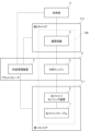
- FIG. 4 is a block diagram showing charge management means in the charge management system according to the first embodiment.
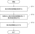
- FIG. 5 is a flow chart showing the operation of the first fee management means in the fee management system according to the first embodiment.
- FIG. 6 is a flow chart showing the operation of the second fee management means in the fee management system according to the first embodiment.
- FIG. 7 is a flow chart showing the operation of the third fee management means in the fee management system according to the first embodiment.
- FIG. 8 is an explanatory diagram showing a concrete example of the services provided in the managed system and the corresponding first charges.
- FIG. 9 is an explanatory diagram showing another specific example of the services provided in the managed system and the corresponding first charges.
- FIG. 10 is a block diagram showing a modification of the charge management system and managed system according to the first embodiment.
- FIG. 11 is a block diagram showing another modification of the charge management system and managed system according to the first embodiment.
- FIG. 12 is a block diagram showing a charge management device and corresponding managed system according to the second embodiment.
- FIG. 13 is a block diagram showing a charge management device according to the second embodiment.
- FIG. 14 is a block diagram showing the hardware configuration of the charge management device according to the second embodiment.
- FIG. 15 is a block diagram showing another hardware configuration of the charge management device according to the second embodiment.
- FIG. 16 is a block diagram showing another hardware configuration of the charge management device according to the second embodiment.
- FIG. 1 is a block diagram showing a fee management system and a corresponding managed system according to the first embodiment.
- FIG. 2 is a block diagram showing the fee management system according to the first embodiment.
- FIG. 3 is an explanatory diagram showing a specific example of charges to be managed by the charge management system according to the first embodiment.
- FIG. 4 is a block diagram showing charge management means in the charge management system according to the first embodiment. A charge management system and a corresponding managed system according to the first embodiment will be described with reference to FIGS. 1 to 4.
- FIG. 1 is a block diagram showing a fee management system and a corresponding managed system according to the first embodiment.
- the managed system 100 includes an optical fiber cable 1, an optical fiber sensing device 2, an analysis engine 3 and a communication line 4.
- the optical fiber cable 1 is composed of an existing optical fiber cable for communication or a dedicated optical fiber cable for optical fiber sensing.
- the optical fiber cable 1 is installed in any manner. Specifically, for example, the optical fiber cable 1 is installed on a plurality of utility poles or a plurality of steel towers. Alternatively, for example, the optical fiber cable 1 is buried underground.
- the optical fiber cable 1 may be an optical fiber composite ground wire (OPGW).
- OPGW optical fiber composite ground wire
- the optical fiber sensing device 2 is provided at the end of the optical fiber cable 1 .
- the optical fiber sensing device 2 performs optical fiber sensing using the optical fiber cable 1 . More specifically, the optical fiber sensing device 2 performs Distributed Fiber Optic Sensing (DFOS) using the optical fiber cable 1 .
- DFOS Distributed Fiber Optic Sensing
- the DFOS executed by the optical fiber sensing device 2 includes at least one of DVS (Distributed Vibration Sensing), DAS (Distributed Acoustic Sensing), or DTS (Distributed Temperature Sensing).
- the optical fiber sensing device 2 is composed of at least one of a DVS device, a DAS device and a DTS device.
- the optical fiber sensing device 2 outputs a pulsed optical signal.
- the output optical signal is input to the optical fiber of the optical fiber cable 1 .
- the input optical signal propagates inside such an optical fiber.
- backscattered light is generated at successive points in the laying direction (that is, longitudinal direction) of the optical fiber cable 1 .
- the amplitude, wavelength, frequency, etc. of such backscattered light will vary depending on vibration, pressure, temperature, etc. at the corresponding point.
- the optical fiber sensing device 2 receives such backscattered light.
- the optical fiber sensing device 2 detects a physical quantity related to vibration, pressure or temperature at the corresponding point, which is a predetermined physical quantity at each of the continuous points based on the amplitude, phase, frequency, etc. of the received backscattered light. do.
- Raw data, flow data, or the like relating to the detected physical quantity is thereby obtained.
- the DVS device detects physical quantities related to vibration at each of the continuous points.
- vibration data raw data, flow data, or the like
- the DAS device detects physical quantities related to pressure at each of the successive points.
- acoustic data raw data, flow data, etc.
- the DTS device detects a physical quantity related to temperature at each of the continuous points.
- temperature data raw data, flow data, etc.
- Sensing data includes at least one of vibration data, acoustic data, and temperature data, for example.
- the optical fiber sensing device 2 outputs sensing data.
- the analysis engine 3 acquires the output sensing data.
- the analysis engine 3 analyzes the acquired sensing data based on a predetermined algorithm.
- the analysis engine 3 is configured by, for example, a dedicated AI (Artificial Intelligence) engine.
- AI Artificial Intelligence
- Such an AI engine is generated by prior machine learning, for example.
- AI engine is provided, for example, in a so-called “cloud”. That is, the analysis engine 3 is configured by, for example, a cloud computer.
- the optical fiber sensing device 2 can freely communicate with the analysis engine 3 .
- the optical fiber sensing device 2 may communicate with the analysis engine 3 via an edge computer (not shown).
- the analysis engine 3 is owned by the platformer P.
- the analysis engine 3 is provided by the platformer P.
- the platformer P provides the user U with services based on the results of analysis by the analysis engine 3 . That is, the platformer P is the platformer for such services.
- services may be simply referred to as "services”.
- a specific example of the algorithm in the analysis engine 3 and a specific example of the service provided by the platform P will be described later with reference to FIGS. 8 and 9.
- Platformer P is, for example, a cloud service provider.
- the analysis engine 3 can be realized using a cloud computer.
- the charge management system 200 can be realized using a cloud computer.
- the user U is, for example, a so-called "end user”.
- the user U is the same person as the carrier (described later) of the optical fiber cable 1 .
- the optical fiber cable 1 is owned by the carrier of the optical fiber cable 1 (hereinafter sometimes referred to as the "first carrier") C_1.
- the fiber optic cable 1 is provided by the first carrier C_1.
- the optical fiber sensing device 2 is sold by the platformer P to the first carrier C_1 or lent by the platformer P to the first carrier C_1.
- the optical fiber sensing device 2 may be owned by the first carrier C_1.
- the first carrier C_1 may be a telecommunications carrier.
- the first carrier C_1 may be an electric power company.
- the first carrier C_1 may be the road administrator.
- the communication line 4 is used for the provision of services to the user U by the platformer P.
- the communication line 4 is configured by, for example, a public electric communication line or a dedicated electric communication line.
- the communication line 4 may be one using the Internet.
- the communication line 4 is owned by the carrier of the communication line 4 (hereinafter sometimes referred to as “second carrier”) C_2.
- the communication line 4 is provided by the second carrier C_2.
- the second carrier C_2 is typically a telecommunications carrier. Note that when the first carrier C_1 is a telecommunications carrier, the second carrier C_2 may be the same carrier as the first carrier C_1.
- the managed system 100 is configured in this manner.
- the fee management system 200 is a system for managing fees in the managed system 100 .
- the fee management system 200 includes fee management means 11.
- the fee management means 11 is means for managing fees in the managed system 100 .
- the fee management means 11 is configured by, for example, a cloud computer. Note that the fee management system 200 is owned by the platform P, as shown in FIG. In other words, the fee management system 200 is provided by the platform P. That is, the fee management means 11 is provided by the platform P.
- the charges to be managed by the charge management means 11 include the following first charges.
- the charges to be managed by the charge management means 11 can include at least one of the following second charges and third charges.
- the first fee is a fee paid as a service usage fee. That is, the first fee is paid by the user U to the platformer P.
- the amount of the first fee varies depending on the usage status of the service by the user U. Specifically, for example, the amount of the first charge differs depending on the distance ⁇ of the portion of the optical fiber cable 1 corresponding to the sensing data used for the service that the user U uses. Also, for example, the amount of the first fee varies depending on the time ⁇ at which the sensing data is acquired. Further, for example, when the service used by the user U is a service for detecting the occurrence of a predetermined event (e.g., abnormality or deterioration) in a predetermined object (e.g., individual utility poles or individual steel towers), the amount of the first charge varies depending on the quantity (for example, the number) ⁇ of the target objects. Also, for example, the amount of the first charge varies depending on the number ⁇ of services that the user U uses. Also, for example, the amount of the first charge varies depending on the usage period ⁇ of the service that the user U uses.
- a predetermined event e.g.
- the amount of the first fee is calculated based on these parameters ( ⁇ to ⁇ ). Specifically, for example, for at least one of distance ⁇ , time ⁇ , and quantity ⁇ , a unit for calculating the amount of the first fee is set in advance. Also, a unit price corresponding to each unit is set in advance. By multiplying the number of units and the unit price, a basic fee corresponding to the usage amount of the service by the user U (hereinafter sometimes referred to as "usage amount fee") is calculated. Also, for example, a discount rate or a discount amount for the usage fee is set according to at least one of the number ⁇ and the usage period ⁇ . The discount rate or discount amount is calculated using, for example, a predetermined formula including variables corresponding to these parameters ( ⁇ , ⁇ ). Alternatively, for example, the discount rate or discount amount is set to a predetermined value according to these parameters ( ⁇ , ⁇ ). The amount of the first charge is calculated by discounting the calculated usage amount charge based on the set discount rate or discount amount.
- the second fee is a fee paid as a usage fee for sensing data. That is, the second fee is paid by the platformer P to the first carrier C_1.
- the amount of the second charge varies depending on the usage state of the sensing data by the first carrier C_1. Specifically, for example, the amount of the second fee differs according to the data amount ⁇ of the sensing data provided to the platformer P by the first carrier C_1. The amount of the second fee is calculated by so-called "pay-as-you-go" based on the value of the data amount ⁇ , for example.
- a third fee is a fee paid as a usage fee for the communication line 4 . That is, the third fee is paid by the user U to the second carrier C_2. However, in the managed system 100, the third fee is paid via the platform P.
- the amount of the third charge varies depending on the state of use of the communication line 4 by the user U. Specifically, for example, the amount of the third charge varies depending on the amount of communication ⁇ using the communication line 4 by the user U.
- the amount of the third charge is calculated by pay-as-you-go billing, for example, based on the value of the amount of communication ⁇ .
- the charge management means 11 manages the first charge, the second charge, and the third charge.
- the charge management means 11 comprises a first charge management means 21, a second charge management means 22 and a third charge management means .
- the first fee management means 21 is means for managing the first fee.
- management of the first charge includes at least calculation of the amount of the first charge.
- the first fee management means 21 acquires information on the usage status of the service by the user U.
- information may be referred to as "first usage state information”.
- the first usage state information includes, for example, at least one of information indicating the distance ⁇ , information indicating the time ⁇ , and information indicating the quantity ⁇ .
- the first user information includes, for example, at least one of information indicating the number ⁇ and information indicating the period of use ⁇ .
- the first charge management means 21 calculates the amount of the first charge using the acquired first usage state information. A specific example of how to calculate such amount is as described above. That is, the first fee management means 21 calculates the usage amount fee by multiplying the number of units and the unit price based on the values of the parameters ( ⁇ to ⁇ ) included in the obtained first usage state information. Next, the first charge management means 21 discounts the calculated usage amount charge according to the values of the parameters ( ⁇ , ⁇ ) included in the first usage state information obtained above. Thus, the amount of the first charge is calculated.
- the first fee management means 21 outputs information including the calculated amount (hereinafter sometimes referred to as "first fee information") to the outside.
- first fee information information including the calculated amount (hereinafter sometimes referred to as "first fee information") to the outside.
- the platformer P is notified of the amount of the first charge.
- the amount of the first fee may be notified to the user U instead of or in addition to being notified to the platform P.
- the user U can know the amount of the first fee to be paid to the platformer P.
- the platformer P can confirm whether the amount is appropriate. In this way, management of the first fee is realized.
- the second charge management means 22 is means for managing the second charge.
- the management of the second charge includes at least calculation of the amount of the second charge.
- the second fee management means 22 acquires information on the usage status of the sensing data by the platformer P.
- information may be referred to as "second usage state information”.
- the second usage state information includes, for example, information indicating the data amount ⁇ . Such information is collected by the platformer P from the first carrier C_1 and managed by the platformer P, for example.
- the second charge management means 22 calculates the amount of the second charge using the acquired second usage state information.
- a specific example of how to calculate such amount is as described above. That is, the second charge management means 22 calculates the amount of the second charge by pay-as-you-go charging based on the value of the parameter ( ⁇ ) included in the obtained second usage state information.
- the second fee management means 22 outputs information including the calculated amount (hereinafter sometimes referred to as "second fee information") to the outside.
- second fee information information including the calculated amount (hereinafter sometimes referred to as "second fee information") to the outside.
- the platformer P is notified of the amount of the second charge.
- the amount of the second fee may be notified to the first carrier C_1 instead of or in addition to being notified to the platformer P. This allows the platformer P to know the amount of the second fee to be paid to the first carrier C_1.
- the first carrier C_1 can confirm whether the amount is appropriate. In this way, management of the second fee is realized.
- the third charge management means 23 is means for managing the third charge.
- management of the third charge includes at least calculation of the amount of the third charge.
- the third fee management means 23 acquires information on the usage status of the communication line 4 by the user U.
- information may be referred to as "third usage state information”.
- the third usage state information includes, for example, information indicating traffic ⁇ .
- Such information is collected by the platformer P from the second carrier C_2 or the user U, and managed by the platformer P, for example.
- the third charge management means 23 uses the acquired third usage state information to calculate the amount of the third charge.
- a specific example of how to calculate such amount is as described above. That is, the third charge management means 23 calculates the amount of the third charge by pay-as-you-go charging based on the value of the parameter ( ⁇ ) included in the acquired third usage state information.
- the third charge management means 23 outputs information including the calculated amount (hereinafter sometimes referred to as "third charge information") to the outside.
- the platformer P is notified of the amount of the third charge.
- the amount of the third fee may be notified to the user U and the second carrier C_2 instead of or in addition to being notified to the platform P.
- the user U can know the amount of the third charge to be paid via the platformer P.
- the second carrier C_2 can confirm whether the amount is appropriate. In this way, management of the third toll is realized.
- the charge management system 200 is configured in this manner.
- FIG. 5 the operation of the charge management system 200 will be explained. More specifically, the operation of the charge management means 11 will be described with reference to the flow charts shown in FIGS. 5 to 7.
- FIG. 5 the flow charts shown in FIGS. 5 to 7.
- the first charge management means 21 acquires first usage state information (step ST1).
- first usage state information A specific example of the content of the first usage state information and a specific example of the acquisition source of the first usage state information have already been described. Therefore, repetitive description is omitted.
- the first charge management means 21 uses the first usage state information acquired in step ST1 to calculate the amount of the first charge (step ST2).
- a specific example of the method of calculating the amount of money has already been described. Therefore, repetitive description is omitted.
- the first fee management means 21 outputs information including the amount calculated in step ST2 (that is, first amount information) to the outside (step ST3). As a result, at least the platformer P is notified of the amount of the first charge.
- the second fee management means 22 acquires second usage state information (step ST11).
- a specific example of the content of the second usage state information and a specific example of the acquisition source of the second usage state information have already been described. Therefore, repetitive description is omitted.
- the second charge management means 22 uses the second usage state information acquired in step ST11 to calculate the amount of the second charge (step ST12).
- step ST11 A specific example of the method of calculating the amount of money has already been described. Therefore, repetitive description is omitted.
- the second fee management means 22 outputs information including the amount calculated in step ST12 (that is, second amount information) to the outside (step ST13). As a result, at least the platformer P is notified of the amount of the second charge.
- the third charge management means 23 acquires the third usage state information (step ST21).
- a specific example of the content of the third usage state information and a specific example of the acquisition source of the third usage state information have already been described. Therefore, repetitive description is omitted.
- the third charge management means 23 uses the third usage state information acquired in step ST21 to calculate the amount of the third charge (step ST22).
- a specific example of the method of calculating the amount of money has already been described. Therefore, repetitive description is omitted.
- the third charge management means 23 outputs information including the amount calculated in step ST22 (that is, third amount information) to the outside (step ST23). As a result, at least the platformer P is notified of the amount of the third charge.
- the platformer P stores information (hereinafter referred to as "position (refer to FIG. 8). That is, the platformer P provides a so-called “Lat-long” service. Hereinafter, such a service may be referred to as a “location coordinate information generation service”.
- the platformer P acquires information about the optical fiber cable 1 (hereinafter sometimes referred to as "cable information") from the first carrier C_1.
- the cable information includes, for example, information indicating the length of the optical fiber cable 1, information indicating the installation position of the optical fiber cable 1, and information indicating the installation mode (installation, burying, etc.) of the optical fiber cable 1.
- the platformer P Based on the cable information, the platformer P generates a predetermined vibration at a point corresponding to predetermined position coordinates among the laying positions of the optical fiber cable 1 .
- An existing device such as a heavy machine
- the optical fiber sensing device 2 detects the distance in the optical fiber cable 1, which is the distance from the installation position of the optical fiber sensing device 2 to the vibration generating position.
- the platformer P acquires data indicating the detected distance (that is, sensing data for rat long) from the first carrier C_1.
- the platformer P associates the position coordinates of the point where the vibration was generated with the distance indicated by the acquired data. These processes are executed for each of a plurality of points. In this way, position coordinate information is generated.
- the function of generating position coordinate information may be implemented by the analysis engine 3 .
- the analysis engine 3 may generate position coordinate information by analyzing data based on the Lat-long algorithm as described above.
- the location coordinate information generation service is a service provided by the platformer P to the first carrier C_1. That is, the user of the location coordinate information generation service (“first user U_1” in the figure) is the first carrier C_1. For this reason, the first carrier C_1 pays the corresponding first fee to the platformer P as the usage fee for the location coordinate information generation service.
- This first charge is managed by the first charge management means 21 .
- the platformer P provides a service that detects the occurrence of a given event by analyzing sensing data using the analysis engine 3 (see FIGS. 8 and 9).
- a service that detects the occurrence of a given event by analyzing sensing data using the analysis engine 3 (see FIGS. 8 and 9).
- an event detection service Such a service may be referred to as an "event detection service”.
- the events to be detected by the event detection service (hereinafter sometimes referred to as “detection target events”) depend on the installation mode of the optical fiber cable 1 (installation using multiple utility poles, installation using multiple steel towers, burying, etc.).
- the detection target event is deterioration of individual utility poles, abnormality of individual utility poles, deterioration of individual steel towers, abnormality of individual steel towers, damage to the optical fiber cable 1 in the ground, or It is a disconnection of the optical fiber cable 1 .
- the analysis engine 3 analyzes sensing data based on the following algorithm. That is, in the analysis engine 3, information indicating the pattern of vibration of the optical fiber cable 1 when the event to be detected occurs is prepared in advance. On the other hand, the analysis engine 3 uses the vibration data included in the acquired sensing data to detect the vibration pattern for each distance in the optical fiber cable 1 . These patterns are, for example, patterns showing vibration intensity against time or patterns showing vibration intensity against frequency.
- the analysis engine 3 compares the detected pattern with the previously prepared pattern. As a result, the analysis engine 3 determines whether or not the detection target event occurs for each distance in the optical fiber cable 1 . In this way, the occurrence of the detectable event is detected.
- the platformer P provides the user U with the result of such detection. This implements an event detection service.
- the analysis engine 3 uses the position coordinate information generated by the position coordinate information generation service to detect the position coordinates of the point where the detection target event occurs.
- the platformer P also provides the user U with the result of detection of the position coordinates. As a result, not only can the user U be notified of the occurrence of the detection target event, but also the user U can be notified of the position of the point where the detection target event is occurring.
- the event detection service can be said to be a service provided to the user U by the platformer P. That is, the user U is the user of the event detection service (“second user U_2” in the figure). For this reason, the user U pays the corresponding first fee to the platformer P as a usage fee for the event detection service. This first charge is managed by the first charge management means 21 .
- the platformer P provides a service for updating the generated position coordinate information after the position coordinate information is generated by the position coordinate information generation service (see FIG. 9).
- a service for updating the generated position coordinate information after the position coordinate information is generated by the position coordinate information generation service (see FIG. 9).
- a service may be referred to as a "location coordinate information update service”.
- the processing executed in the position coordinate information update service is the same as the processing executed in the position coordinate information generation service.
- the algorithm in the location coordinate information update service is a Lat-long algorithm similar to the algorithm in the location coordinate information generation service. Therefore, detailed description is omitted.
- the correspondence relationship between the distance and the positional coordinates in the optical fiber cable 1 can change due to various factors (for example, troubled movement of the optical fiber cable 1).
- By updating the location coordinate information with the location coordinate information update service and using the updated location coordinate information for the event detection service it is possible to implement an event detection service that responds to such changes.
- the location coordinate information update service is a service provided by the platformer P to the first carrier C_1. That is, the user of the location coordinate information update service (“first user U_1” in the drawing) is the first carrier C_1. Therefore, the first carrier C_1 pays the corresponding first fee to the platformer P as the usage fee for the location coordinate information update service.
- This first charge is managed by the first charge management means 21 .
- the location coordinate information update service (see FIG. 9) is a paid service
- the location coordinate information generation service (see FIG. 8) may be a free service. That is, the amount of the first charge corresponding to the position coordinate information generation service may be calculated as 0 yen by the first charge management means 21 .
- the second carrier C_2 may be the same operator as the first carrier C_1 (for example, a telecommunications operator). That is, the optical fiber cable 1 and the communication line 4 may be provided by the same carrier C as shown in FIG. Also, the optical fiber sensing device 2 may be sold or lent to such a carrier C.
- the charge management system 200 may be provided by a business operator different from the service platform P (for example, a cloud service business operator). For example, as shown in FIG. 11, the charge management system 200 is provided by another platform (“second platform P_2" in the figure) different from the service platform ("first platform P_1" in the figure). It can be anything.
- the fee management system 200 may manage only the first fee out of the first fee, the second fee and the third fee. That is, the charge management means 11 may include only the first charge management means 21 out of the first charge management means 21, the second charge management means 22 and the third charge management means 23. FIG.
- the charge management system 200 may manage only the first charge and the second charge among the first charge, the second charge and the third charge. That is, the charge management means 11 includes only the first charge management means 21 and the second charge management means 22 out of the first charge control means 21, the second charge control means 22 and the third charge control means 23. can be
- the charge management system 200 may manage only the first charge and the third charge out of the first charge, the second charge and the third charge. That is, the charge management means 11 includes only the first charge management means 21 and the third charge management means 23 out of the first charge control means 21, the second charge control means 22 and the third charge control means 23. can be
- the charges to be managed by the charge management means 11 may be the charges in the managed system 100, and are not limited to the first, second and third charges.
- the charge subject to the management may include the following fourth charge. That is, the fourth fee is a fee paid by the first carrier C_1 to the platformer P as a usage fee for the optical fiber sensing device 2 .
- the fee management system 200 includes fee management means 11 that manages fees related to optical fiber sensing.
- the fee includes a first fee paid to the service platformer P by the service user U as a service usage fee for a service based on data obtained by optical fiber sensing.
- the charge management means 11 the first charge can be managed. That is, it is possible to manage the fee paid by the user U to the platformer P as consideration for using the service.
- the charge management means 11 acquires first usage state information regarding the usage state of the service by the user U, and uses the first usage state information to calculate the amount of the first charge. By using the first usage state information, it is possible to calculate the amount of money corresponding to the usage state of the service by the user U for the first fee.
- the fee also includes a second fee paid as a usage fee for data (sensing data) by the platformer P to the first carrier C_1 that provides the optical fiber cable 1 used for optical fiber sensing.
- the second charge can be managed.
- the charge management means 11 acquires second usage state information regarding the usage state of data (sensing data) by the platformer P, and uses the second usage state information to calculate the amount of the second charge. By using the second usage state information, it is possible to calculate the amount of money according to the usage state of the sensing data by the platformer P for the second charge.
- the fee includes a third fee paid by the user U to the second carrier C_2, which provides the communication line 4 used for providing the service, as a usage fee for the communication line 4.
- the charge management means 11 acquires third usage state information regarding the usage state of the communication line 4 by the user U, and uses the third usage state information to calculate the amount of the third charge. By using the third usage state information, it is possible to calculate the third charge according to the usage state of the communication line 4 by the user U.
- FIG. 1 A block diagram
- the third charge is paid by the user U to the second carrier C_2 via the platform P.
- management of the third fee can be realized in the platform P.
- the fee management means 11 is provided by the platform P.
- management of each fee can be realized in the service platform P (for example, cloud service provider).
- first carrier C_1 and the second carrier C_2 are the same carrier C (see FIGS. 1 and 10).
- carrier C can increase the number of users of communication line 4 by providing sensing data.
- carrier C can be given an incentive to provide sensing data.
- FIG. 12 is a block diagram showing a charge management device and corresponding managed system according to the second embodiment.
- FIG. 13 is a block diagram showing a charge management device according to the second embodiment.
- a charge management device and a corresponding managed system according to the second embodiment will be described with reference to FIGS. 12 and 13.
- FIG. 12 and 13 elements similar to those shown in FIGS. 1 and 2 are denoted by the same reference numerals, and description thereof is omitted.
- a fee management device 5 is provided instead of the fee management system 200 according to the first embodiment.
- the fee management device 5 is a device for managing fees in the managed system 100 .
- the fee management device 5 includes fee management means 11.
- the fee management means 11 of the fee management device 5 is similar to the fee management means 11 of the fee management system 200 according to the first embodiment. That is, the fee management means 11 includes a first fee management means 21 (not shown in FIG. 13).
- the charge management means 11 may comprise at least one of the second charge management means 22 and the third charge management means 23 (not shown in FIG. 13).
- the fee management means 11 is as explained in the first embodiment. Therefore, repetitive description is omitted.
- the fee management device 5 is configured in this way.
- FIG. 14 the hardware configuration of the charge management device 5 will be described with reference to FIGS. 14 to 16.
- FIG. 14 the hardware configuration of the charge management device 5 will be described with reference to FIGS. 14 to 16.
- the fee management device 5 is composed of a computer 31.
- the computer 31 includes a processor 41 and a memory 42.
- Memory 42 stores a program for causing computer 31 to function as fee management means 11 .
- the processor 41 reads and executes programs stored in the memory 42 . Thereby, the function of the charge management means 11 is realized.
- the computer 31 includes a processing circuit 43 as shown in FIG.
- the processing circuit 43 executes processing for causing the computer 31 to function as the fee management means 11 . Thereby, the function of the charge management means 11 is realized.
- the computer 31 comprises a processor 41, a memory 42 and a processing circuit 43.
- part of the functions of the charge management means 11 are implemented by the processor 41 and the memory 42 , and the rest of the functions of the charge management means 11 are implemented by the processing circuit 43 .
- the processor 41 is composed of one or more processors.
- the individual processors use, for example, CPUs (Central Processing Units), GPUs (Graphics Processing Units), microprocessors, microcontrollers, or DSPs (Digital Signal Processors).
- CPUs Central Processing Units
- GPUs Graphics Processing Units
- microprocessors microcontrollers
- DSPs Digital Signal Processors
- the memory 42 is composed of one or more memories. Individual memories are those using volatile memory or non-volatile memory. Specifically, for example, individual memories include RAM (Random Access Memory), ROM (Read Only Memory), flash memory, EPROM (Erasable Programmable Read Only Memory), EEPROM (Electrically Erasable Programmable Rea d Only Memory), solid state Drives, hard disk drives, flexible discs, compact discs, DVDs (Digital Versatile Discs), Blu-ray discs, MO (Magneto Optical) discs, or mini discs are used.
- RAM Random Access Memory
- ROM Read Only Memory
- flash memory EPROM (Erasable Programmable Read Only Memory)
- EEPROM Electrical Erasable Programmable Rea d Only Memory
- solid state Drives hard disk drives, flexible discs, compact discs, DVDs (Digital Versatile Discs), Blu-ray discs, MO (Magneto Optical) discs, or mini discs are used.
- the processing circuit 43 is composed of one or more processing circuits. Individual processing circuits are, for example, ASIC (Application Specific Integrated Circuit), PLD (Programmable Logic Device), FPGA (Field Programmable Gate Array), SoC (System a Chip), or system LSI (Lar ge Scale Integration) is.
- ASIC Application Specific Integrated Circuit
- PLD Programmable Logic Device
- FPGA Field Programmable Gate Array
- SoC System a Chip
- system LSI Long ge Scale Integration
- the operation of the fee management device 5 is the same as the operation of the fee management system 200 described in the first embodiment. Therefore, repetitive description is omitted.
- the charge management device 5 can employ various modifications similar to those described in the first embodiment. Description of these modified examples will be omitted.
- the effect of the fee management device 5 is the same as the effect of the fee management system 200 described in the first embodiment. Therefore, repetitive description is omitted.
- [Appendix] [Appendix 1] Equipped with fee management means for managing fees related to optical fiber sensing, wherein the fee includes a first fee paid to a platformer of the service as a usage fee for the service by a user of the service for the service based on the data obtained by the optical fiber sensing. system.
- the charge management means acquires first usage state information relating to the usage state of the service by the user, and calculates the amount of the first charge using the first usage state information. 1.
- the charge management system according to 1.
- [Appendix 3] 2. The charge according to appendix 1 or 2, wherein the fee includes a second fee paid to a first carrier that provides an optical fiber cable used for the optical fiber sensing as a fee for using the data by the platformer.
- the charge management means acquires second usage state information relating to the usage state of the data by the platformer, and calculates the amount of the second charge using the second usage state information. 3.
- the charge management system according to 3. [Appendix 5] wherein the fee includes a third fee paid by the user to a second carrier that provides a communication line used for providing the service as a usage fee for the communication line.
- the charge management means is characterized in that it acquires third usage state information relating to the usage state of the communication line by the user, and calculates the amount of the third charge using the third usage state information.
- [Appendix 7] The charge management system according to appendix 5 or appendix 6, wherein the third charge is paid by the user to the second carrier via the platformer.
- [Appendix 8] The charge management system according to any one of appendices 1 to 7, wherein the charge management means is provided by the platformer.
- [Appendix 9] Equipped with fee management means for managing fees related to optical fiber sensing, wherein the fee includes a first fee paid to a platformer of the service as a usage fee for the service by a user of the service for the service based on the data obtained by the optical fiber sensing. Device.
- the charge management means acquires first usage state information relating to the usage state of the service by the user, and calculates the amount of the first charge using the first usage state information.
- the charge management device according to 9.
- the charge management means acquires second usage state information relating to the usage state of the data by the platformer, and calculates the amount of the second charge using the second usage state information. 11. The charge management device according to 11.
- the fee management device according to any one of .
- the charge management means is characterized in that it acquires third usage state information relating to the usage state of the communication line by the user, and calculates the amount of the third charge using the third usage state information.
- [Appendix 15] 15.
- the fee management device according to appendix 13 or 14, wherein the third fee is paid by the user to the second carrier via the platformer.
- the charge management device according to any one of appendices 9 to 15, wherein the charge management means is provided by the platformer.
- the fee management means manages fees for optical fiber sensing; wherein the fee includes a first fee paid to a platformer of the service as a usage fee for the service by a user of the service for the service based on the data obtained by the optical fiber sensing.
- Method. [Appendix 18]
- the charge management means acquires first usage state information relating to the usage state of the service by the user, and calculates the amount of the first charge using the first usage state information. 17.
- the fee management method according to 17.
- the charge management means acquires second usage state information relating to the usage state of the data by the platformer, and calculates the amount of the second charge using the second usage state information. 19. The fee management method according to 19 above.
- the charge management means is characterized in that it acquires third usage state information relating to the usage state of the communication line by the user, and calculates the amount of the third charge using the third usage state information.
- [Appendix 25] recording a program for causing a computer to function as fee management means for managing fees related to optical fiber sensing; A recording medium, wherein the charge includes a first charge to be paid by a user of the service to a platformer of the service as a usage charge for the service based on the data obtained by the optical fiber sensing. .
- the charge management means acquires first usage state information relating to the usage state of the service by the user, and calculates the amount of the first charge using the first usage state information. 26.
- the charge management means acquires second usage state information relating to the usage state of the data by the platformer, and calculates the amount of the second charge using the second usage state information. 28.
- the recording medium according to 27.
- the fee includes a third fee paid by the user to a second carrier that provides a communication line used for providing the service as a usage fee for the communication line.
- the recording medium according to any one of [Appendix 30] The charge management means is characterized in that it acquires third usage state information relating to the usage state of the communication line by the user, and calculates the amount of the third charge using the third usage state information. 29.
- optical fiber cable 1 optical fiber cable 2 optical fiber sensing device 3 analysis engine 4 communication line 5 fee management device 11 fee management means 21 first fee management means 22 second fee management means 23 third fee management means 31 computer 41 processor 42 memory 43 processing circuit 100 Managed system 200 Fee management system
Landscapes
- Business, Economics & Management (AREA)
- Strategic Management (AREA)
- Engineering & Computer Science (AREA)
- Physics & Mathematics (AREA)
- General Physics & Mathematics (AREA)
- Finance (AREA)
- Theoretical Computer Science (AREA)
- Development Economics (AREA)
- Economics (AREA)
- Marketing (AREA)
- Accounting & Taxation (AREA)
- General Business, Economics & Management (AREA)
- Entrepreneurship & Innovation (AREA)
- Game Theory and Decision Science (AREA)
- Health & Medical Sciences (AREA)
- General Health & Medical Sciences (AREA)
- Human Resources & Organizations (AREA)
- Primary Health Care (AREA)
- Tourism & Hospitality (AREA)
- Management, Administration, Business Operations System, And Electronic Commerce (AREA)
Priority Applications (2)
| Application Number | Priority Date | Filing Date | Title |
|---|---|---|---|
| JP2023557873A JPWO2023079605A1 (https=) | 2021-11-04 | 2021-11-04 | |
| PCT/JP2021/040487 WO2023079605A1 (ja) | 2021-11-04 | 2021-11-04 | 料金管理システム、料金管理装置及び料金管理方法 |
Applications Claiming Priority (1)
| Application Number | Priority Date | Filing Date | Title |
|---|---|---|---|
| PCT/JP2021/040487 WO2023079605A1 (ja) | 2021-11-04 | 2021-11-04 | 料金管理システム、料金管理装置及び料金管理方法 |
Publications (1)
| Publication Number | Publication Date |
|---|---|
| WO2023079605A1 true WO2023079605A1 (ja) | 2023-05-11 |
Family
ID=86240800
Family Applications (1)
| Application Number | Title | Priority Date | Filing Date |
|---|---|---|---|
| PCT/JP2021/040487 Ceased WO2023079605A1 (ja) | 2021-11-04 | 2021-11-04 | 料金管理システム、料金管理装置及び料金管理方法 |
Country Status (2)
| Country | Link |
|---|---|
| JP (1) | JPWO2023079605A1 (https=) |
| WO (1) | WO2023079605A1 (https=) |
Citations (3)
| Publication number | Priority date | Publication date | Assignee | Title |
|---|---|---|---|---|
| US6271766B1 (en) * | 1998-12-23 | 2001-08-07 | Cidra Corporation | Distributed selectable latent fiber optic sensors |
| CN108731752A (zh) * | 2018-05-29 | 2018-11-02 | 四川原皓源环境工程有限公司 | 一种中央空调用气量动态监控方法、装置及费用统计系统 |
| WO2021176683A1 (ja) * | 2020-03-06 | 2021-09-10 | 日本電気株式会社 | 光ファイバセンシングシステム、光ファイバセンシング方法、及び光ファイバセンシング装置 |
-
2021
- 2021-11-04 JP JP2023557873A patent/JPWO2023079605A1/ja active Pending
- 2021-11-04 WO PCT/JP2021/040487 patent/WO2023079605A1/ja not_active Ceased
Patent Citations (3)
| Publication number | Priority date | Publication date | Assignee | Title |
|---|---|---|---|---|
| US6271766B1 (en) * | 1998-12-23 | 2001-08-07 | Cidra Corporation | Distributed selectable latent fiber optic sensors |
| CN108731752A (zh) * | 2018-05-29 | 2018-11-02 | 四川原皓源环境工程有限公司 | 一种中央空调用气量动态监控方法、装置及费用统计系统 |
| WO2021176683A1 (ja) * | 2020-03-06 | 2021-09-10 | 日本電気株式会社 | 光ファイバセンシングシステム、光ファイバセンシング方法、及び光ファイバセンシング装置 |
Also Published As
| Publication number | Publication date |
|---|---|
| JPWO2023079605A1 (https=) | 2023-05-11 |
Similar Documents
| Publication | Publication Date | Title |
|---|---|---|
| Sevillano et al. | DYNAMAP-Development of low cost sensors networks for real time noise mapping | |
| Singh et al. | Development of an adaptive neuro fuzzy inference system based vehicular traffic noise prediction model | |
| US8020616B2 (en) | Determining a status in a wellbore based on acoustic events detected by an optical fiber mechanism | |
| CN114623922A (zh) | 分布式光纤传感预警系统及其控制方法、设备、存储介质 | |
| AU2016344513A1 (en) | Monitoring traffic flow | |
| CA3208890A1 (en) | Distributed fiber-optic sensing systems, devices, and methods | |
| Bontempi et al. | Systemic approach for the maintenance of complex structural systems | |
| Nobles et al. | Comparing costs of onsite best management practices to nutrient credits for stormwater management: A case study in Virginia | |
| JP2026501563A (ja) | 既存の通信ケーブルを介した車両・インフラストラクチャ相互作用に基づく車両の検知と分類 | |
| JP2002298063A (ja) | 浸水予測と排水管理をするためのリアル浸水マップシステムおよびその方法 | |
| Praticò et al. | Innovative smart road management systems in the urban context: Integrating smart sensors and miniaturized sensing systems | |
| WO2023079605A1 (ja) | 料金管理システム、料金管理装置及び料金管理方法 | |
| KR20220145785A (ko) | 홍수예측방법 및 홍수예측장치 | |
| Tran et al. | Real-time flood forecasting using time-varying parameter hydrological model: case study for Ta Trach reservoir | |
| US20220129805A1 (en) | Digital platform for automated assessing and rating of construction and erection risks, and method thereof | |
| Sangin et al. | Analogy between SCS-CN and Muskingum methods | |
| Tiwari et al. | Strategies and implications of noise pollution monitoring, modelling, and mitigation in urban cities | |
| Walch et al. | Floating Car Data–Based Short-Term Travel Time Forecasting with Deep Recurrent Neural Networks Incorporating Weather Data | |
| Wirahadikusumah et al. | Application of dynamic programming and simulation for sewer management | |
| JP7632653B2 (ja) | 事象検出装置、事象検出システム及び事象検出方法 | |
| US12028110B2 (en) | Distributed fiber optic sensor placement | |
| Marzouk et al. | Framework for assessing bridges construction impact on work zone traffic using BrIM | |
| Urquijo et al. | Real options of distributed DAS sensing applied to road transport engineering | |
| Epple et al. | From the Lab to the Structure: Monitoring of a German Road Bridge Using Embedded Ultrasonic Transducers and Coda Waves | |
| CN113483778A (zh) | 一种基于车联网干涉的智能导航方法、装置和电子设备 |
Legal Events
| Date | Code | Title | Description |
|---|---|---|---|
| 121 | Ep: the epo has been informed by wipo that ep was designated in this application |
Ref document number: 21963203 Country of ref document: EP Kind code of ref document: A1 |
|
| ENP | Entry into the national phase |
Ref document number: 2023557873 Country of ref document: JP Kind code of ref document: A |
|
| NENP | Non-entry into the national phase |
Ref country code: DE |
|
| 122 | Ep: pct application non-entry in european phase |
Ref document number: 21963203 Country of ref document: EP Kind code of ref document: A1 |