WO2023075477A1 - Cooking apparatus - Google Patents
Cooking apparatus Download PDFInfo
- Publication number
- WO2023075477A1 WO2023075477A1 PCT/KR2022/016622 KR2022016622W WO2023075477A1 WO 2023075477 A1 WO2023075477 A1 WO 2023075477A1 KR 2022016622 W KR2022016622 W KR 2022016622W WO 2023075477 A1 WO2023075477 A1 WO 2023075477A1
- Authority
- WO
- WIPO (PCT)
- Prior art keywords
- coupling
- link
- moving assembly
- heater
- motor
- Prior art date
Links
- 238000010411 cooking Methods 0.000 title claims abstract description 180
- 230000008878 coupling Effects 0.000 claims abstract description 208
- 238000010168 coupling process Methods 0.000 claims abstract description 208
- 238000005859 coupling reaction Methods 0.000 claims abstract description 208
- 235000013305 food Nutrition 0.000 claims abstract description 66
- 238000001514 detection method Methods 0.000 claims abstract description 21
- 238000000034 method Methods 0.000 claims description 15
- 230000007423 decrease Effects 0.000 claims description 7
- 238000012546 transfer Methods 0.000 claims description 2
- 230000008901 benefit Effects 0.000 abstract description 5
- 238000007667 floating Methods 0.000 description 57
- 230000001681 protective effect Effects 0.000 description 56
- 230000033001 locomotion Effects 0.000 description 21
- 230000002441 reversible effect Effects 0.000 description 10
- 238000011065 in-situ storage Methods 0.000 description 9
- 230000036961 partial effect Effects 0.000 description 8
- 230000000149 penetrating effect Effects 0.000 description 6
- 238000009434 installation Methods 0.000 description 5
- 230000008569 process Effects 0.000 description 5
- 238000003303 reheating Methods 0.000 description 5
- 230000002452 interceptive effect Effects 0.000 description 4
- 230000003014 reinforcing effect Effects 0.000 description 4
- 238000005452 bending Methods 0.000 description 3
- 230000000903 blocking effect Effects 0.000 description 3
- 230000008859 change Effects 0.000 description 3
- 230000000994 depressogenic effect Effects 0.000 description 3
- 230000000694 effects Effects 0.000 description 3
- 238000010438 heat treatment Methods 0.000 description 3
- 239000000463 material Substances 0.000 description 3
- 230000002829 reductive effect Effects 0.000 description 3
- 238000013459 approach Methods 0.000 description 2
- 230000001174 ascending effect Effects 0.000 description 2
- 230000005540 biological transmission Effects 0.000 description 2
- 239000013013 elastic material Substances 0.000 description 2
- 235000013611 frozen food Nutrition 0.000 description 2
- 238000003780 insertion Methods 0.000 description 2
- 230000037431 insertion Effects 0.000 description 2
- NLYAJNPCOHFWQQ-UHFFFAOYSA-N kaolin Chemical compound O.O.O=[Al]O[Si](=O)O[Si](=O)O[Al]=O NLYAJNPCOHFWQQ-UHFFFAOYSA-N 0.000 description 2
- 230000007246 mechanism Effects 0.000 description 2
- 238000004806 packaging method and process Methods 0.000 description 2
- 238000010257 thawing Methods 0.000 description 2
- 230000000712 assembly Effects 0.000 description 1
- 238000000429 assembly Methods 0.000 description 1
- 238000010276 construction Methods 0.000 description 1
- 238000009499 grossing Methods 0.000 description 1
- 238000012423 maintenance Methods 0.000 description 1
- 239000007769 metal material Substances 0.000 description 1
- 238000012986 modification Methods 0.000 description 1
- 230000004048 modification Effects 0.000 description 1
- 230000009467 reduction Effects 0.000 description 1
- 230000002787 reinforcement Effects 0.000 description 1
- 238000000926 separation method Methods 0.000 description 1
Images


Classifications
-
- H—ELECTRICITY
- H05—ELECTRIC TECHNIQUES NOT OTHERWISE PROVIDED FOR
- H05B—ELECTRIC HEATING; ELECTRIC LIGHT SOURCES NOT OTHERWISE PROVIDED FOR; CIRCUIT ARRANGEMENTS FOR ELECTRIC LIGHT SOURCES, IN GENERAL
- H05B6/00—Heating by electric, magnetic or electromagnetic fields
- H05B6/64—Heating using microwaves
- H05B6/76—Prevention of microwave leakage, e.g. door sealings
Definitions
- the present invention relates to a cooking appliance equipped with a heater capable of moving up and down inside a cooking chamber.
- the cooking appliance is an appliance that cooks food accommodated therein by using heat from a heater, which is a heating source.
- the cooking appliance is generally composed of a main body having a cooking chamber, which is a space for accommodating food, one or more heaters provided in the main body, and a door rotatably coupled to the main body to open and close the front of the cooking chamber.
- the food defrosting device disclosed in US Registration No. US4303820 is provided with a pair of flat electrodes, and one of the electrodes is configured to move to put frozen food. And it provides a relatively low wattage power supply that evenly distributes energy to food for gentle heating (thawing).
- US registration number US8258440 discloses an apparatus and method for reheating a package of refrigerated or frozen food. It has a conductive heat transfer contact with the food packaging, reheats the food packaging to the reheating temperature during the reheating time in the reheating mode, and maintains the temperature in the maintenance mode after the food reaches the reheating temperature.
- an object of the present invention is to solve the problems of the prior art as described above, and to provide a cooking appliance in which a heater artificially moves up and down inside a cooking chamber.
- An object of the present invention is to provide a cooking appliance that effectively shields electromagnetic waves passing through the periphery of a heater system that ascends and descends.
- An object of the present invention is to provide a cooking appliance that stops descending and returns to its original position when a moving assembly or heater descending inside a cooking chamber collides with food.
- An object of the present invention is to provide a cooking appliance that transmits power by a female (-) male (+) coupling so that power transmission is blocked when a moving assembly or a heater collides with food.
- a pair of female (-) male (+) couplings in which concavo-convex ( ⁇ ) of a shape corresponding to each other are formed and coupled is provided
- connection couplings having coupling protrusions and coupling grooves formed in corresponding shapes and selectively coupled to each other are provided to transmit or block the rotation of the motor to the lead screw.
- a cooking appliance includes a case having a cooking compartment inside, a door for opening and closing the cooking compartment, a moving assembly installed to move up and down inside the cooking compartment, and the moving assembly interfering with food inside the cooking compartment. It includes a food detection system that detects whether or not it is; The food detection system is characterized in that it is provided with a pair of connecting couplings formed and coupled to each other in corresponding shapes.
- connection coupling may be provided between a motor that generates rotational power and a lead screw interlocked according to the rotational power of the motor, and transmits rotational power of the motor to the leadscrew.
- connection couplings are characterized in that coupling protrusions and coupling grooves formed in corresponding shapes and selectively coupled to each other are formed, respectively.
- a center protrusion and a center hole formed in a shape corresponding to each other and rotatably coupled are formed, respectively.
- Each of the coupling protrusion and the coupling groove is characterized in that two or more are formed.
- the width of the coupling protrusion is smaller than that of the coupling groove.
- the coupling protrusion may have a width smaller than that of the coupling groove by 0.1 mm.
- the width of the coupling protrusion is characterized in that the size gradually decreases toward one end.
- the width of the coupling groove is characterized in that the size gradually increases toward one end.
- the end of the center protrusion is characterized in that it is formed to protrude outward more than an outer edge of at least one of the pair of connection couplings.
- One of the pair of connection couplings is connected to the motor shaft of the motor, and the other is coupled to one end of the lead screw.
- connection couplings are coupled to the motor shaft or lead screw by interference fitting or screwing.
- the cooking appliance according to the present invention has the following effects.
- the heater can flow up and down inside the cooking chamber. Therefore, since the heater can be brought close to the food in the cooking chamber to cook, heat loss can be minimized and the cooking time of the food can be shortened.
- a link assembly including a plurality of links is provided for vertical movement of the moving assembly equipped with a motor.
- a traction kit for assisting the operation of the link is further provided to operate in a specific section when the moving assembly rises.
- a food detection system for detecting whether or not interference with food is provided when the moving assembly descends. Therefore, when the food and the moving assembly come into contact, the descending of the moving assembly is stopped, thereby preventing damage to food and parts.
- a female (-) coupling and a male (+) coupling consisting of a male (-) and a male (+) are respectively provided to constitute a pair of connection couplings, and these connection couplings provide rotational power. It is provided between the generating motor and the lead screw to transmit the rotational power of the motor to the lead screw, and when the moving assembly interferes with food, the coupling between the female (-) coupling and the male (+) coupling is released, so that the motor Rotational motion is not transmitted to the moving assembly. Therefore, there is an advantage in preventing an increase in the load of the motor.
- a center protrusion and a center hole in which a female (-) coupling and a male (+) coupling are rotatably coupled to each other are formed, respectively, and the female (-) male (+) +)
- the center protrusion remains inserted into the center hole. Therefore, even when the female (-) male (+) couplings come close to each other again due to the reverse rotation of the motor, the concentricity of the female (-) male (+) couplings is maintained, making it easy to combine the coupling protrusion and the coupling groove.
- FIG. 1 is a perspective view showing the internal structure of a cooking appliance in a state in which an outer cover is removed in a preferred embodiment of the cooking appliance according to the present invention
- FIG. 2 is a perspective view showing the configuration of a flow heater system constituting an embodiment of the present invention.
- FIG. 3 is an exploded perspective view showing the configuration of a flow heater system constituting an embodiment of the present invention.
- FIG. 4 is a plan view of the flow heater system shown in FIG. 2;
- FIG. 5 is a front view of the flow heater system shown in FIG. 2;
- FIG. 6 is a side view of the flow heater system shown in FIG. 2;
- FIG. 7 is a front cross-sectional view of the flow heater system shown in FIG. 2;
- FIG. 8 is a perspective view showing a state when a heater descends in the flow heater system shown in FIG. 2;
- FIG. 9 is a plan view of the flow heater system shown in FIG. 8.
- FIG. 10 is a front view of the flow heater system shown in FIG. 8;
- FIG. 11 is a side view of the flow heater system shown in FIG. 8;
- FIG. 12 is an exploded perspective view showing the configuration of a fixed assembly constituting a flow heater system of a cooking appliance according to the present invention
- FIG. 13 is an exploded perspective view showing the configuration of a moving assembly constituting a flow heater system of a cooking appliance according to the present invention
- FIG. 14 is an exploded perspective view showing the configuration of a link assembly constituting a flow heater system of a cooking appliance according to the present invention.
- 15 is an exploded perspective view showing the configuration of an upper plate, a protective cover, and a fixing frame constituting an embodiment of the present invention.
- 16 is a perspective view showing the configuration of a guide member constituting an embodiment of the present invention.
- 17 is an exploded perspective view showing the configuration of moving control means constituting an embodiment of the present invention.
- Fig. 18 is a front view showing the configuration of moving control means constituting an embodiment of the present invention.
- 19 is a perspective view showing the configuration of a fixing bracket constituting an embodiment of the present invention.
- Figure 20 is a perspective view showing the configuration of the floating bracket constituting the embodiment of the present invention.
- 21 is a perspective view showing the configuration of a protection bracket constituting an embodiment of the present invention.
- 22 is a perspective view showing the configuration of a location bracket constituting an embodiment of the present invention.
- FIG. 23 is an exploded perspective view showing the configuration of a heater housing and an insulating member constituting an embodiment of the present invention
- 24 is a perspective view showing the configuration of a support end of a moving assembly constituting an embodiment of the present invention.
- 25 is an exploded perspective view showing the main configuration of a link assembly constituting an embodiment of the present invention.
- 26 is a perspective view showing a coupled state of a link assembly constituting an embodiment of the present invention and a moving control means;
- FIG. 27 is a front view showing a state in which a moving assembly is located at a specific height according to the operation of a link assembly constituting an embodiment of the present invention
- 28 is a partial cross-sectional view showing a state in which an in-situ detection means constituting an embodiment of the present invention is installed.
- 29 is a partially enlarged view showing the configuration and operating state of the in-situ detection means constituting the embodiment of the present invention.
- FIG. 30 is a cutaway perspective view showing the configuration of the flow heater system shown in FIG. 8;
- Fig. 31 is a partial front cross-sectional view showing the construction of shielding means constituting an embodiment of the present invention.
- 32 is a front view showing the configuration of a food detection system constituting an embodiment of the present invention.
- FIG. 33 is a plan view of a flow heater system constituting another embodiment of a cooking appliance according to the present invention.
- FIG. 34 is a front sectional view of a flow heater system constituting another embodiment of a cooking appliance according to the present invention.
- 35 is a perspective view of a floating bracket constituting another embodiment of the cooking appliance according to the present invention.
- Figure 36 is a plan view of the floating bracket shown in Figure 35;
- FIG. 38 is a perspective view of a traction kit constituting an embodiment of the present invention.
- Fig. 39 is a plan view of Fig. 38;
- Fig. 40 is a BB' cross-sectional view of Fig. 39;
- Fig. 41 is a cross-sectional view taken along line C-C' of Fig. 39;
- FIG. 43 is a perspective view of a pull hook constituting an embodiment of the present invention.
- Fig. 44 is a plan view of Fig. 43;
- Fig. 45 is a bottom view of Fig. 43;
- Fig. 46 is a front view of Fig. 43;
- Fig. 47 is a left side view of Fig. 43;
- 49 is a partial front cross-sectional view showing a state in which a heater is lowered by a link assembly constituting an embodiment of the present invention
- 50 is a partial front sectional view showing an operating state of a traction kit constituting an embodiment of the present invention.
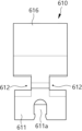
- connection coupling 51 is a perspective view of a connection coupling constituting another embodiment of a cooking appliance according to the present invention.
- FIG. 52 is an exploded perspective view of the connecting coupling shown in FIG. 51;
- FIG. 53 is a front cross-sectional view showing a state in which female (-) male (+) of the connection coupling shown in FIG. 51 are partially coupled;
- FIG. 54 is a front cross-sectional view showing a disengaged state of the female (-) male (+) connection couplings shown in FIG. 51;
- FIG. 55 is a front view showing the configuration of a food detection system to which the connection coupling of FIG. 51 is applied;
- FIG. 56 is a front view showing the configuration of a moving control means to which the connection coupling of FIG. 51 is applied;
- the cooking appliance according to the present invention may be various types of food cooking appliances such as a microwave oven or an electric oven.
- FIG. 1 is a perspective view of an embodiment of a cooking appliance according to the present invention. That is, FIG. 1 shows a perspective view of the main components of the inside of the cooking appliance in a state in which the outer cover is removed for description of the cooking appliance according to the present invention.
- the cooking appliance according to the present invention includes a case 10 in which a cooking chamber 12 is formed therein, and a door 20 provided on one side of the case 10 to open and close the cooking chamber 12. made up of etc.
- the case 10 serves as a main body of the cooking appliance, and may be formed in a rectangular box shape as shown, and is preferably opened at the front for storing or withdrawing food.
- a door 20 for shielding when cooking food is provided.
- This door 20 may be rotatably installed around a hinge to open and close.
- a front frame 14 is provided on the front of the case 10 to form a front appearance of the case 10, and various display units (not shown) or deco panels may be further provided thereto.
- a support plate 30 for supporting food or containers may be provided inside the cooking chamber 12, and the support plate 30 may be rotatably installed.
- the flow heater system 100 is provided on the upper side of the case 10 as shown.
- the flow heater system 100 is a system that allows a heater to flow vertically inside the cooking chamber 12 .
- a heater for generating heat may be provided on the upper side of the case 10, and two or more such heaters may be provided. That is, a heater is also provided in the flow heater system 100 to flow up and down the cooking chamber 12, and in addition to the flow heater system 100, a heater may be further provided in the case 10.
- the cooking appliance according to the present invention has a sensing function for detecting whether the heater of the flow heater system 100 is in contact with food in the cooking chamber 12 or has a certain distance, and the flow heater system ( 100) A function of detecting a return of a heater to an original position may be provided.
- FIGS. 2 to 14 show the configuration of the flow heater system 100. That is, FIGS. 2 and 3 show a perspective view and an exploded perspective view showing the configuration of the flow heater system 100, respectively, and FIGS. 4 to 7 show a plan view, front view, side view, and front view of the flow heater system 100. Cross-sectional views are shown, respectively.
- FIG. 8 shows a perspective view of the flow heater system 100 in a state in which the internal heater is lowered
- FIGS. 9 to 11 show plan and front views of the flow heater system 100 shown in FIG. A side view is shown, respectively.
- FIGS. 12 to 14 show exploded perspective views of a fixed assembly, a moving assembly, and a link assembly constituting the flow heater system 100, respectively.
- the flow heater system 100 is provided with a heater 210 that generates heat, and this heater 210 can be installed to flow vertically inside the cooking chamber 12. .
- case 10 or the flow heater system 100 has a sensing function for detecting whether the heater 210 is in contact with food in the cooking chamber 12 or has a certain distance, and the heater 210 A function of detecting a return to the original position of may be provided.
- the moving heater system 100 includes a moving assembly 200 to which the heater 210 is mounted and protected, and a fixed assembly provided on one side of the case 10 to control the up and down movement of the moving assembly 200 ( 300), and a link assembly 400 provided on one side of the moving assembly 200 so that the moving assembly 200 is connected to the fixed assembly 300 in a flexible manner.
- the moving assembly 200 is made separate from the case 10 and is installed so as to be able to move up and down inside the cooking chamber 12, and is configured to cover at least the side of the heater 210 so that the heater 210 It is preferable to be configured so that the heat of the is concentrated to the lower side and not dissipated to the side.
- the fixing assembly 300 is fixedly installed on the upper side of the case 10 to support the moving assembly 200 to move vertically in a state supported on the upper surface of the case 10 .
- a moving control means 500 for forcing the moving assembly 200 to move up and down under the control of the link assembly 400 is provided in the fixed assembly 300 .
- the link assembly 400 may be provided on the upper side of the moving assembly 200, and is configured to include one or more links, so that the moving assembly 200 is connected to the fixed assembly 300. is guided to flow up and down.
- Upper and lower ends of the link assembly 400 may be rotatably connected to the fixed assembly 300 and the moving assembly 200, respectively.
- the fixing assembly 300 is provided on the upper plate 310 forming the upper surface of the cooking chamber 12 and the upper plate 310 to close the gap between the moving assembly 200 and the fixing assembly 300. It may be composed of a protective cover 320 that blocks electromagnetic waves through the upper plate 310 and a fixed frame 330 provided on the upper side of the upper plate 310 to support the moving control means 500 .
- the upper plate 310 may be formed in the shape of a square flat plate having a predetermined thickness to form the upper surface of the cooking chamber 12 .
- the central portion of the upper plate 310 may penetrate vertically to provide a passage through which the moving assembly 200 flows vertically.
- the fixing frame 330 may be installed to be spaced apart from the protective cover 320 .
- the protective cover 320 may also be configured to have a rectangular shape as a whole like the upper plate 310, and the central portion of the protective cover 320 also vertically like the upper plate 310.
- a through hole may be formed to have a square frame shape. Therefore, the moving assembly 200 can move up and down through the central hole of the upper plate 310 and the protective cover 320 .
- the fixing frame 330 may be formed in a square shape smaller than a rectangular hole formed in the central portion of the protective cover 320, and thus the fixing frame 330 and the protective cover 320 ), a predetermined gap is formed between them, and it is preferable that the heater housing 220 of the moving assembly 200 to be described below is accommodated in this gap and moves up and down.
- the fixing frame 330 may be fixedly installed on the upper side of the upper plate 310, and for this purpose, a fixing guide 340 may be further provided between the upper plate 310 and the fixing frame 330.
- the fixing guide 340 may have a ' ⁇ ' shape (when viewed from the front). Accordingly, the fixing guide 340 may have an upper end coupled to the fixing frame 330 and a lower end fixed to the upper plate 310 or the protective cover 320 .
- the fixing guide 340 includes a frame coupling portion 342 coupled to the fixing frame 330 and an upper coupling portion 344 fixed to the upper plate 310 or protective cover 320. It may be made, and in the present invention, the case where the lower end of the fixing guide 340, the upper coupling part 344 is fastened to the upper surface of the upper plate 310 is exemplified.
- the fixing guide 340 may be provided in plurality, and in the present invention, two fixing guides 340 are installed front and rear at a predetermined distance on the upper side of the upper plate 310 to support the fixing frame 330. foreshadowing that
- the fixing assembly 300 may be provided with a sliding rail 350 that supports a floating bracket 560 or a lead nut 530 to be described below in a sliding manner.
- sliding rails 350 are provided on the upper surface of the fixed frame 330 to have a predetermined length from side to side, and to these sliding rails 350, floating brackets 560 or lead nuts 530 to be described below are provided. It can be installed so that it can move left and right.
- a moving control means 500 may also be provided on the upper side of the fixed frame 330 .
- the moving control unit 500 includes a motor 510 generating rotational power, a lead screw 520 provided on one side of the motor 510 and rotating in conjunction with rotation generated by the motor 510, and , a lead nut 530 fastened to the lead screw 520 by screwing, and a connection coupling 540 connecting one end of the lead screw 520 and a motor shaft.
- the motor 510 generates rotational power, and a stepping motor or the like may be used for precise rotation control.
- a stepping motor may be capable of supplying forward and reverse rotational motion according to a rotational angle through pulse control.
- the lead screw 520 has a male screw formed on an outer surface of a thin cylinder having a predetermined length, and a lead nut 530 having a female screw corresponding to the male screw of the lead screw 520 is fastened thereto. Accordingly, when the lead screw 520 is rotated by the power of the motor 510, the lead nut 530 moves left and right along the lead screw 520. As such, the lead screw 520 and the lead nut 530 (Nut) play a role of changing forward/reverse rotational motion into linear motion.
- connection coupling 540 connecting one end of the lead screw 520 and a motor shaft may be further provided. That is, as shown, a connection coupling 540 may be further provided at the motor shaft protruding from the right end of the lead screw 520 and the left side of the motor 510 .
- connection coupling 540 is used for the purpose of reducing power loss due to concentricity error between the shaft of the motor 510 and the shaft of the lead screw 520 and smoothing the rotation, and is a flexible coupling. coupling) is preferably used. That is, as the connection coupling 540, an MST or MSTS type flexible coupling may be used.
- the motor 510 is installed on a fixing bracket 550 fixedly mounted to the fixing assembly 300, and the lead nut 530 is attached to a floating bracket 560 movably installed on the fixing assembly 300. can be fitted
- the fixing frame 330 is spaced apart from the upper side of the upper plate 310 by the fixing guide 340, and a gap of a certain size is formed between the fixing frame 330 and the protective cover 320. formed to form a moving passage of the heater housing 220 to be described below.
- a fixed bracket 550 and a floating bracket 560 are provided on the upper side of the fixing frame 330 of the fixing assembly 300, respectively.
- the fixing bracket 550 is fixedly mounted on the upper surface of the fixing frame 330
- the floating bracket 560 is close to or closer to the fixing bracket 550 on the upper side of the fixing frame 330. It is installed flexibly so as to move away from it.
- the sliding rail 350 is fixedly installed on the upper surface of the fixed frame 330, and the sliding member 352 supporting the floating bracket 560 slides on the sliding rail 350. Possibly can be provided.
- a sliding member 352 in the shape of a square plate is installed to slide left and right, and the floating bracket 560 is fixed to the upper surface of the sliding member 352, It can move left and right.
- the motor 510 is mounted on the fixed bracket 550, and the lead nut 530 is mounted on the floating bracket 560. Therefore, when the lead screw 520 rotates according to the rotation of the motor 510 mounted on the fixed bracket 550, the lead nut 530 moves left and right, so that the floating bracket 560 moves to the sliding position. It flows left and right along the rail 350.
- An upper end of a link of the link assembly 400 is rotatably installed in the fixed bracket 550 and the floating bracket 560 . That is, when the left and right upper ends of the 'X' shaped links provided in the link assembly 400 are connected to the fixed bracket 550 and the floating bracket 560, respectively, the left and right movement of the floating bracket 560 According to this, since the left and right upper ends of the 'X'-shaped links are closer to or farther apart from each other, the moving assembly 200 fixed to the lower end of the link assembly 400 moves up and down.
- a protection bracket 360 and a positioning bracket 380 may be further provided on the upper side of the fixing frame 330 of the fixing assembly 300 .
- the protection bracket 360 may be provided on an upper surface of the left end of the fixing frame 330, and includes a protection having a sensing function to protect parts from interference of the heater 210 and food.
- a switch 370 or the like may be installed.
- the protection switch 370 may be made of a microswitch, and is preferably installed to be turned on/off by the moving control means 500.
- This protection switch 370 together with the moving control unit 500 constitutes a food detection system 375 to be described below.
- the protection switch 370 may be installed to be spaced apart from one end of the lead screw 520 by a predetermined distance. That is, as shown, the left end of the lead screw 520 and the protection switch 370 may be installed to be spaced apart from each other by a predetermined distance.
- a protection lever 372 may be further provided in the protection bracket 360 . That is, as shown, between the protection switch 370 and the lead screw 520, there is a protection lever that is forced by the lead screw 520 and selectively presses the protection button 370a of the protection switch 370 ( 372) may be provided.
- the protection lever 372 is turned on by pressing the protection button 370a of the protection switch 370 ( on).
- the positioning bracket 380 may be provided on the upper surface of the right end of the fixing frame 330, which allows the moving assembly 200 to be returned to its original position or to sense its original position.
- a position switch 390 or the like may be installed.
- the protective cover 320 is provided with a plurality of guide members 322 for guiding the vertical flow of the moving assembly 200 . As shown, four guide members 322 may be provided near the corners of the square-shaped protective cover 320, respectively, and these guide members 322 are the heater housing 220 to be described below. When passing through the gap between the fixing frame 330 and the protective cover 320, it serves to support the protective cover 320 so as not to interfere with it.
- the moving assembly 200 may include a heater housing 220 that surrounds and protects the heater 210 and an insulating member 230 provided at one end of the heater housing 220 to block heat or electromagnetic waves.
- the heater housing 220 may be formed in a rectangular box shape, and one or more holes through which hot air from the heater 210 may pass may be vertically formed on a bottom surface.
- the heater housing 220 may flow vertically through a gap between the fixing frame 330 and the protective cover 320 . Accordingly, the heater housing 220 has a rectangular box shape with an open top and a predetermined thickness. It is preferable that the thickness of the four sides of the heater housing 220 is smaller than the size of the gap between the fixing frame 330 and the protective cover 320 .
- a guide groove 222 in which the fixing guide 340 is selectively accommodated may be formed in the heater housing 220 . That is, as shown, guide grooves 222 recessed to have a predetermined length from the top to the bottom are formed on the left and right sides of the heater housing 220, and the moving assembly 200 is formed in these guide grooves 222. When ascending, the frame coupling part 342 of the fixing guide 340 is accommodated.
- the insulating member 230 is preferably formed to have a square shape, and a side end is preferably formed to protrude outward more than a side end of the heater housing 220 . That is, the outer size of the insulating member 230 is formed to be larger than the side size of the heater housing 220 so that when the moving assembly 200 is elevated, the gap between the fixed frame 330 and the protective cover 320 is increased. Through this, it can play a role in blocking electromagnetic waves from leaking to the outside.
- a seating groove 232 in which a lower end of the heater housing 220 is seated may be recessed downward on an upper surface of the insulating member 230 .
- the heater 210 is received and fixed inside the heater housing 220 .
- the heater 210 may be formed long in the left and right or front and back, and it is preferable that a plurality of heaters 210 are provided and installed at the inner lower end of the heater housing 220 .
- Heater brackets 212 are provided at both ends of the plurality of heaters 210 to guide installation of the heaters 210 or supply of power to the heaters 210 .
- a pair of support ends 240 symmetrical to each other may be provided at the inner lower end of the heater housing 220 , and these support ends 240 may support the plurality of heaters 210 .
- the support end 240 may support the lower end of the link assembly 400 . That is, the upper end of the support end 240 may be coupled to the lower end of the link assembly 400 . Accordingly, the moving assembly 200 can move up and down while being fixed to the lower end of the link assembly 400 .
- a heater cover 250 covering the upper part of the heater 210 may be further provided on the upper side of the heater 210, and the heater cover 250 may have a shape corresponding to the number or shape of the heaters 210. there is.
- the link assembly 400 has a configuration including one or more links, and preferably has an upper end rotatably connected to the fixed assembly 300 and a lower end rotatably connected to the moving assembly 200 .
- the link assembly 400 may be composed of a pair of front links 410 and 420 and rear links 430 and 440 installed at a predetermined distance in front and back, and the lower ends of the front links 410 and 420 and the rear links 430 and 440 are A link frame 450 coupled with the moving assembly 200 may be further provided.
- At least one of the left and right lower ends of the front links 410 and 420 and the rear links 430 and 440 be movably installed while being coupled to the link frame 450 .
- the pair of front links 410 and 420 are coupled so that the front 1 link 410 and the front 2 link 420 forming an 'X' shape cross rotatably about the center of each other.
- the pair of rear links 430 and 440 are coupled such that the rear 1 link 430 and the rear 2 link 440 forming an 'X' shape cross rotatably about the center of each other.
- the lower ends of the front 1 link 410 and the rear 1 link 430 installed at a predetermined distance from each other can be connected by a connecting link 460, and the front 2 links 420 and the rear 2 links 440 The bottom of can also be connected to each other by the connection link (460).
- At least one of the left and right lower ends of the front links 410 and 420 and the rear links 430 and 440 is preferably installed movably while being coupled to the link frame 450.
- the front 1 link 410 and the lower end of the rear 1 link 430 are exemplarily installed to be movable to the left and right of the link frame 450.
- a 1-link protruding hole 452 is formed in the left half of the link frame 450 to guide the lower shafts of the front 1-link 410 and the rear 1-link 430 to be inserted so that the left and right rolls are possible.
- the link frame 450 may further include a positioning member 470 for detecting the return of the moving assembly 200 to the original position.
- the positioning member 470 may be formed to protrude upward from the upper surface of the link frame 450 to a predetermined height, and the upper end of the positioning member 470 may selectively interfere with the position switch 390. .
- a home position detecting means for detecting the original position of the moving assembly 200, and a device for detecting whether or not the lower end of the moving assembly 200 is in contact with food inside the cooking chamber 12
- a contact sensing means may be provided.
- the original position detecting means detects whether or not the movement of the moving assembly 200 to the upper side inside the cooking chamber 12 is completed, and may include the position switch 390 or the like.
- the contact detecting means is for detecting whether the lower end of the moving assembly 200 equipped with the heater 210 is in contact with food, and may be composed of the protection switch 370 or the like.
- FIG. 15 is an exploded perspective view of the upper plate 310, the protective cover 320, and the fixing frame 330 constituting the fixing assembly 300.
- the upper plate 310 has a square flat plate shape, and upper holes 312, which are square holes of a predetermined size, are formed inside to penetrate vertically.
- This upper hole 312 becomes a passage through which the moving assembly 200 moves up and down. Therefore, it is preferable that the inner size of the upper hole 312 is larger than the outer size of the heater housing 220 .
- a plurality of choke pieces 314 are formed on the upper plate 310 . That is, as shown, a plurality of choke pieces 314 vertically bent upward are formed extending upward on the inner circumferential surface of the upper plate 310 having a square frame shape.
- a plurality of chalk pieces 314 protruding upward are formed on the edge of the upper hole 312 formed in the central portion of the upper plate 310, and these chalk pieces 314 are formed in the cooking chamber 12 It serves to block internal electromagnetic wave leakage.
- spaced holes 314a in a 'U' shape are formed between the plurality of choke pieces 314 to function as electromagnetic waves extinguishing.
- a choke groove 314b may be further formed in the choke piece 314 .
- the choke groove 314b has a shape that is recessed from the side of the choke piece 314 to one side. That is, as shown, a recessed choke groove 314b recessed outward to a predetermined depth is formed at the center of the choke piece 314 .
- the choke groove 314b may serve to prevent leakage of electromagnetic waves inside the cooking chamber 12 to the outside.
- electromagnetic waves generated inside the cooking chamber 12 may leak to the outside through a gap between the upper plate 310 and the moving assembly 200.
- the electromagnetic waves leaking to the outside through the gap between the upper plate 310 and the moving assembly 200 pass through the gap hole 314a or pass through the choke groove 314b, and the wavelength is dispersed and offset, have a dissipating effect.
- the protective cover 320 preferably has a square frame shape corresponding to the upper plate 310, and the size of the outer edge is preferably slightly smaller than the size of the outer edge of the upper plate 310.
- a protective hole 325 corresponding to the upper hole 312 is formed to penetrate vertically, allowing the heater housing 220 to move up and down.
- the protective cover 320 is preferably formed to be stepped, so that the height of the inner rim is higher than that of the outer rim.
- the protection cover 320 includes a protection step portion 324 formed to have ' ⁇ ' and ' ⁇ ' shaped cross sections (when viewed from the front or rear or left and right), and the lower end of the protection step portion 324. It may be composed of a protective lower portion 326 vertically bent and extended from the side and a protective upper portion 328 vertically bent and extended upward from the inner rim of the protective stepped portion 324.
- a choke piece 314 of the upper plate 310 may be accommodated below the protective stepped portion 324 .
- the fixing frame 330 may be formed to have a ' ⁇ '-shaped cross section (when viewed from the side). Therefore, the fixing frame 330 may be composed of a flat plate-shaped horizontal end 332 having a predetermined thickness, and a vertical end 334 extending by being vertically bent downward from the front and rear ends of the horizontal end 332. there is.
- a pair of link passage holes 336 are vertically formed through the horizontal end 332 .
- the link passage hole 336 is preferably formed to have a predetermined length in left and right directions, and becomes a passage through which a link of the link assembly 400 passes. That is, the pair of front links 410 and 420 and the rear links 430 and 440 are installed or passed through the link passage hole 336 so as to vertically pass through.
- FIG. 16 shows the configuration of the guide member 322 in a perspective view.
- the guide member 322 includes a roller 322a selectively contacting the outer surface of the heater housing 220, a roller shaft 322b serving as a rotational center of the roller 322a, and the roller 322b. (322a) or a roller support portion (322c) for rotatably supporting the roller shaft (322b) and a roller fixing end (322d) bent and extended from the lower end of the roller support portion (322c) and closely fixed to the protective cover (320). etc. can be made.
- the roller 322a may have a cylindrical shape or a cylindrical shape, and may be made of an elastic material such as rubber. Also, the roller 322a may be rotatably connected to the roller shaft 322b, or the roller 322a and the roller shaft 322b may be fixed. When the roller 322a and the roller shaft 322b are fixed or integrally formed, the roller shaft 322b should be rotatably connected to an upper end of the roller support part 322c.
- the roller support 322c may be formed of a flat plate having a predetermined thickness or may have a bent shape.
- the roller fixing end 322d extends from the roller support part 322c and may be bent to be perpendicular to the roller support part 322c or to have a predetermined inclination.
- the roller fixing end 322d is preferably fixedly mounted on the upper surface of the protective step 324 of the protective cover 320 .
- the end (inner end) of the roller 322a partially protrudes into the protective hole 325 of the protective cover 320 to close the gap between the protective cover 320 and the fixing frame 330. It comes into contact with the outer surface of the heater housing 220 passing therethrough.
- 17 and 18 show the moving control unit 500 in an exploded perspective view and a front view.
- the lead screw 520 of the moving control means 500 is formed long to the left and right, and a screw thread is formed on the outer circumferential surface.
- an insertion protrusion 522 protruding to the right is formed at the right end of the lead screw 520 , and the insertion protrusion 522 can be fitted into a groove in the center of the connection coupling 540 .
- the lead nut 530 has a cylindrical shape and is formed to extend vertically with the nut portion 532 through which the lead screw 520 passes, and the nut portion 532 to form the floating bracket 560. ) It may be made of a nut fixing part 534 to be fixed to.
- a female screw corresponding to the male screw formed on the outer circumferential surface of the lead screw 520 is formed on the inner circumferential surface of the nut portion 532 of the lead nut 530, so that the lead screw 520 and the lead nut 530 are screwed together. It is preferable to be configured to do so.
- connection coupling 540 is made of a flexible coupling, and may have a predetermined elasticity from side to side or change a certain amount of length (length reduction and extension) from side to side.
- connection coupling 540 reduces power loss due to concentricity errors between the motor 510 and the lead screw 520 and also functions to smoothly transmit rotation.
- the motor 510 generates rotational power and provides it to the lead screw 520, and the motor shaft 510a of the motor 510 is the right end of the connection coupling 540. It is preferable to be inserted into the central groove and fixed.
- the fixing bracket 550 is formed to have at least a flat top surface and supports the motor 510 to be seated and fixed therefrom, and the motor seating end 552.
- a motor fixing end 554 extending vertically upward to support the side surface of the motor 510, and extending upward from the front and rear ends of the motor seating end 552, respectively, to form the front links 410 and 420 and It may be composed of a link fastening end 556 or the like that rotatably supports the top of the rear links 430 and 440 .
- Fixed fastening ends 558 may be further formed at the left and right ends of the motor seating end 552 to allow the fixing bracket 550 to be fixedly mounted on the upper surface of the fixing frame 330 by a fastening tool such as a bolt. . As shown, the fixed fastening end 558 may be formed to have a position lower than the height of the motor seating end 552 .
- the motor fixing end 554 may be formed to form a vertical plane, and a motor hole 554a penetrating left and right may be formed therein.
- the motor hole 554a is formed to have a diameter of a predetermined size, and a motor shaft (not shown) of the motor 510 or a coupling 540 of the motor 510 is accommodated to pass through the motor hole 554a from side to side. It can be.
- a reinforcement part 556a protruding forward or backward may be further formed on the front or rear surface of the pair of link fastening ends 556 to reinforce strength.
- FIG 20 is a perspective view showing the configuration of the floating bracket 560 is shown. As shown therein, it is preferable that the lower surface of the floating bracket 560 is formed to have a square or rectangular cross-section and is tightly fixed to the upper surface of the sliding member 352 .
- a nut support end 562 is formed to protrude to the right.
- the nut support end 562 supports the lead nut 530 so that it is seated and fixed. It can be configured to support.
- Screw grooves 564 penetrating left and right may be formed in the central portion of the floating bracket 560 to be recessed downward.
- the screw groove 564 is preferably formed larger than the outer diameter of the lead screw 520, and the lead screw 520 can be accommodated therein.
- Upper left link shafts 566 protruding forward and backward are formed on the front and rear surfaces of the floating bracket 560, respectively.
- the upper left link shaft 566 is a part to which an upper end of a link of the link assembly 400 is rotatably connected together with the upper right link shaft 557 . That is, it is preferable that upper ends of the front 2 links 420 and the rear 2 links 440 are rotatably connected to the pair of upper left link shafts 566 .
- reinforcing parts 566a such as the reinforcing part 556a formed at the link fastening end 556, may be further formed on the front and rear surfaces of the floating bracket 560 to protrude forward and backward, respectively.
- 21 is a front perspective view showing the configuration of the protection bracket 360 is shown.
- the protective bracket 360 has a protective support portion 362 formed to have a predetermined size and thickness vertically, and is vertically bent from the lower end of the protective support portion 362 to secure the fixed frame 330. It may be composed of a protective fixing end 364 that is closely fixed to the upper surface.
- a protection switch 370 may be installed in the protection support part 362 to detect whether the moving assembly 200 is in contact with food by interfering with the lead screw 520, and for this purpose, the protection support part ( 362 may further include a protection installation end 366 for supporting the protection switch 370.
- the protective installation end 366 is formed to extend from the rear surface of the protective support part 362 to the rear side to support the protective switch 370.
- 22 is a front perspective view showing the configuration of the location bracket 380 is shown.
- the positioning bracket 380 is vertically bent from the lower end of the positioning support part 382 formed to have a predetermined size and thickness up and down, and the positioning support part 382 to secure the fixed frame 330. It may be composed of a position fixing end 384 that is closely fixed to the upper surface.
- a position switch 390 for detecting whether or not the moving assembly 200 has returned to its original position by interfering with the positioning member 470 may be installed in the position support part 382.
- a position installation end 386 for supporting the position switch 390 and the like may be further provided in the position support part 382 .
- the positioning end 386 extends from the rear surface of the position support part 382 to the rear side to support the position switch 390 and the like.
- the positioning bracket 380 may also be combined with the fixing bracket 550.
- the bracket coupling end 388 at the left end of the positioning bracket 380 is perpendicular to the positioning support part 382. more can be formed.
- FIG. 23 is an exploded perspective view showing the configuration of the heater housing 220 and the insulating member 230 is shown.
- the heater housing 220 has a rectangular box shape with an upper opening, and a heater net 224 is formed on the bottom surface of the heater housing 220 .
- the heater net 224 is preferably configured to have a net shape in which a plurality of upper and lower through holes are formed. This is to ensure that the radiant heat of the heater 210 provided inside the heater housing 220 penetrates the bottom surface of the heater housing 220 and is well transmitted to the lower side.
- the insulating member 230 has an insulating hole 234 penetrating vertically therein so as to have a square frame shape, and the moving assembly 200 is placed back to the top of the cooking chamber 12. In this case, it can play a role of preventing external leakage such as electronic board by shielding the gap between the protective cover 320 and the fixing frame 330.
- the size of the insulating member 230 is preferably larger than the inner diameters of the upper hole 312 and the protection hole 325 . That is, the horizontal and vertical external dimensions of the insulating member 230 having a square shape are formed larger than the horizontal and vertical dimensions of the inner diameters of the upper hole 312 and the protection hole 325, so that the moving assembly 200 is installed in the cooking chamber. It is preferable to prevent electromagnetic waves inside the cooking chamber 12 from leaking to the outside by partially overlapping the insulating member 230 and the upper plate 310 when they are placed in the original position at the upper end of the cooking chamber 12 .
- 24 is a perspective view showing the configuration of the support end 240 of the moving assembly 200.
- the pair of support ends 240 are installed in a shape symmetrical to each other from side to side, and support the plurality of heaters 210 and the like, and at the same time, the moving assembly 200 moves the link assembly 400 ) It is preferable to be configured to be coupled to the bottom of the.
- the support end 240 supports the heater 210 by protruding upward from one end of the bottom support part 242 closely fixed to the top surface of the bottom surface of the heater housing 220 and the bottom support part 242. It may be composed of a heater seating portion 244 and a link connection portion 246 formed by being vertically bent upward from the other end of the bottom support portion 242 to extend.
- the link connection part 246 may be formed to have a size larger than the vertical height of the heater seating part 244, and the link of the link assembly 400 is at the top of the link connection part 246.
- the lower surface of the frame 450 may be tightly fixed.
- One or more grooves through which the heater 210 passes or is supported may be formed in the heater mounting portion 244 so as to be recessed downward, and the heater bracket 212 may be fixed.
- 25 is an exploded perspective view showing the main configuration of the link assembly 400 is shown.
- the front 1 link 410 and the front 2 link 420 rotatably cross each other in an 'X' shape centered on each other, and the rear 1 link 430 and the rear 2 link 440 intersect each other rotatably in an 'X' shape centered on each other.
- a link center shaft 412 and a link center hole 422 formed in corresponding shapes and rotatably coupled to each other are formed at the central portions of the front 1 link 410 and the front 2 link 420, respectively.
- the link center axis 412 is formed in the front 1 link 410
- the link center hole 422 is formed in the front 2 links 420.
- the link center axis 412 is formed to protrude forward or rearward from the front or rear center of the front 1 link 410
- the link center hole 422 is formed to protrude forward or backward from the center of the front 2 link 420. It is formed to penetrate, so that the link center axis 412 of the front 1 link 410 can be inserted into the link center hole 422 of the front 2 link 420 and installed rotatably.
- a link center shaft 412 and a link center hole 422 rotatably coupled to each other are formed in the central portions of the rear 1 link 430 and the rear 2 link 440, respectively.
- the link center axis 412 is formed in the rear 1 link 430
- the link center hole 422 is formed in the rear 2 links 440. .
- 1 link holes 414 penetrating back and forth are formed, respectively, and in these 1 link holes 414, the upper link shaft of the fixing bracket 550 ( 557) is rotatably inserted and engaged.
- Two link holes 424 penetrating back and forth are formed at the upper ends of the front two links 420 and the rear two links 440, respectively. In these two link holes 424, the upper left link shaft of the floating bracket 560 ( 566) is rotatably inserted and engaged.
- a 1-link protrusion 416 may be formed to protrude forward or backward, and this 1-link protrusion 416 may be formed to protrude forward or backward. Connected.
- two-link protrusions 426 may be formed to protrude forward or backward, and these two-link protrusions 426 may be formed to protrude forward or backward. Connected.
- the link frame 450 includes a bottom portion 454 made of a flat plate having a predetermined thickness, and a link connection end 456 formed by bending vertically upward from the front and rear ends of the bottom portion 454 and extending therefrom. ), etc.
- the lower ends of the front 1 link 410 and the rear 1 link 430 and the lower ends of the front 2 links 420 and the rear 2 links 440 may be rotatably connected to the link connection end 456, respectively.
- the left half of the link connection end 456 has a 1-link protrusion hole 452 in which a 1-link protrusion 416 formed at the lower ends of the front 1-link 410 and the rear 1-link 430 is accommodated. ) is formed to penetrate from front to back.
- the one-link protrusion hole 452 is preferably formed to have a predetermined length left and right, so that the one-link protrusion 416 can move left and right while being accommodated in the one-link protrusion hole 452. do.
- 1-link protrusion grooves 452a recessed downward may be formed at both left and right ends of the 1-link protrusion hole 452, respectively.
- the 1-link protrusion groove 452a allows the moving assembly 200 to temporarily maintain a stopped state after moving up and down, and is a place where the 1-link protrusion 416 can temporarily stay.
- the right half of the link connection end 456 has a 2-link protrusion hole 458 in which a 2-link protrusion 426 formed at the lower ends of the front 2-link 420 and the rear 2-link 440 is accommodated. ) is formed to penetrate from front to back.
- the 2-link projection 426 maintains a state accommodated in the 2-link projection hole 458, and the 1-link projection 416 moves left and right while being accommodated in the 1-link projection hole 452. Since it is movable, the lower ends of the front 1 link 410 and the rear 1 link 430 may be closer or farther from the lower ends of the front 2 links 420 and the rear 2 links 440, so that the link connection end ( 456) can move up and down.
- the height at which the heater 210 descends inside the cooking chamber can be arbitrarily set. That is, the height at which the heater 210 descends inside the cooking chamber or the height at which the heater 210 is positioned when cooking inside the cooking chamber can be set by a user or a designer. That is, it is preferable that the heater 210 descending inside the cooking chamber by the rotation (normal rotation or reverse rotation) of the motor 510 or the descending height of the moving assembly 200 in which the heater 210 is installed can be set by a user or the like. do.
- the height at which the heater 210 or the moving assembly 200 descends inside the cooking chamber may be set to 2 or more. That is, the height at which the heater 210 or the moving assembly 200 descends is set in advance, and the user selects the set position to automatically lower the heater 210 or the moving assembly 200 to the set height to perform cooking. will be able to do it
- FIG. 26 and 27 show a state in which the link assembly 400 moves up and down by the rotation of the motor 510 . That is, FIG. 26 is a perspective view showing a coupled state of the link assembly 400 and the moving control means 500, and FIG. 27 shows a state where the heater 210 is located at a specific height inside the cooking chamber.
- FIG. 27(a) is a front view showing the state of the link assembly 400 when the heater 210 and the moving assembly 200 are in their original position at the top of the cooking chamber
- FIG. 27(b) is a front view showing the heater 210 and the moving assembly ( 200) is a front view showing the state of the link assembly 400 when it descends to the first position inside the cooking chamber
- FIG. 27(c) shows the heater 210 and the moving assembly 200 at the second position inside the cooking chamber. It is a front view showing the state of the link assembly 400 when it descends.
- the moving assembly 200 coupled to the link frame 450 of the link assembly 400 moves inside the cooking chamber. It flows up and down, and eventually the heater 210 flows up and down inside the cooking chamber to reach a specific position so that cooking can be performed.
- FIG. 27(a) shows a state in which the upper and lower ends of the respective links are close to each other, which may indicate a state in which the heater 210 and the moving assembly 200 are positioned at the upper end of the inside of the cooking chamber. there is. That is, it may be the case that the height at which the heater 210 and the moving assembly 200 descend into the cooking chamber is 0 mm.
- 27(b) may show a state in which the heater 210 and the moving assembly 200 reach the first position set by the designer or the user. That is, it may be the case that the height at which the heater 210 and the moving assembly 200 descend into the cooking chamber is 46 mm. In this way, when the heater 210 descends inside the cooking chamber, cooking efficiency can be improved by being closer to the food.
- the heater 210 and the moving assembly 200 may show a state in which the heater 210 and the moving assembly 200 reach the second position set by the designer or the user. That is, the height at which the heater 210 and the moving assembly 200 descend into the cooking chamber may be 92 mm. Of course, the descending height should be set smaller than the height inside the cooking chamber. As such, when the heater 210 descends to the lower end of the inside of the cooking chamber, cooking efficiency can be improved by being closer to food.
- the heater 210 and the moving assembly 200 must rise again to the top of the cooking chamber and return to their original position. At this time, the heater 210 or the moving assembly 200 must return to its original position Sensing may be accomplished by in situ sensing means.
- FIG. 28 and 29 show the configuration and installation state of the home position detecting means for detecting whether the heater 210 or the moving assembly 200 is located in the original position. That is, FIG. 28 is a partial cross-sectional view showing a state in which the in-situ sensing means is installed on one side of the case 10, and FIG. 29 is a partially enlarged view showing the configuration and operation of the in-situ sensing means.
- the flow heater system 100 may be provided with an in-situ detection means 395 for detecting whether or not the heater 210 is located in the in-situ position.
- the home position detecting means 395 includes a position switch 390 provided on one side of the flow heater system 100 and a position lever 394 for selectively pressing the position button 392 of the position switch 390. and a positioning member 470 that selectively pushes the positioning lever 394 according to the vertical movement of the heater 210.
- the position switch 390 may be installed on the position bracket 380, and the position lever 394 may also be installed on the position bracket 380.
- the position lever 394 may be installed at a location other than the position bracket 380, but in the present invention, as shown, the position lever 394 is installed vertically together with the position switch 390 on the position bracket 380. case is exemplified.
- the positioning member 470 may be installed in the link assembly 400 . That is, the positioning member 470 is formed to protrude upward from the upper surface of the link frame 450 to a predetermined height so that the upper end can selectively interfere with the position switch 390 .
- a positioning member 470 may also be installed on the moving assembly 200 in addition to the link frame 450 .
- the position lever 394 may be formed to have elasticity due to its own material or shape. That is, the position lever 394 is formed to have a predetermined length, and may have elasticity or be made of an elastic material so that bending may occur due to the shape of the position lever 394 having a predetermined length.
- the position lever 394 may have a shape bent one or more times as shown.
- a contact end 394a for directly or indirectly pressing the position button 392 of the position switch 390 and one end of the position member 470 selectively come into contact with each other.
- the contact end 394a is formed at the end (right end in FIG. 29) of the position lever 394, and is a position button 392 provided in the position switch 390 or will be described below.
- the guide lever 392b is pressed upward (in FIGS. 28 and 29).
- the fixing part 394d may have a circular ring shape, and is fixedly installed to the location bracket 380.
- the coupling part 394e protrudes from the fixing part 394d to one side (downward right in FIG. 29), and the right end (in FIG. 29) is integrally connected to the interference part 394b.
- the interference portion 394b is a portion that selectively directly contacts the upper end of the positioning member 470, and is preferably installed horizontally as shown. This is to enable the upper end of the positioning member 470 to move upward.
- the connecting portion 394c extends further to the right from the right end of the interference portion 394b, and is preferably bent at a predetermined angle with the interference portion 394b. That is, as shown, it is preferable that the right end of the connection part 394c is positioned above the left end (in FIG. 29).
- the contact end 394a may be integrally formed at the end (right end in FIG. 29) of the connection part 394c, and is formed to be horizontal to hold the position button 392 or the guide lever 392b. It is preferably configured to be easily pushed upward.
- the position switch 390 may include one or more terminals 392a and a position button 392.
- the position button 392 is commonly called an actuator, and is a mechanism that directly or indirectly receives an external force to operate a switch and transmits the operation to the inside to open and close the switch .
- the position switch 390 may further include a guide lever 392b installed to have elasticity and directly contact the position button 392 .
- This guide lever (392b) is formed to have a predetermined length, it is preferably made of a metal material or the like to have elasticity.
- the position lever 394 may be configured to directly press the position button 392, and the position switch 390 may When there is a guide lever 392b, the position button 392 may be pressed by the guide lever 392b by allowing the position lever 394 to press the guide lever 392b.
- the moving assembly 200 and the heater 210 described above can move up and down inside the cooking chamber by the rotation of the motor 510 constituting the moving control means 500.
- the movement of the moving assembly 200 and the heater 210 may be configured to stop when the position button 392 of the position switch 390 is pressed. That is, when the moving assembly 200 and the heater 210, which have descended into the cooking chamber, rise, the moving assembly 200 or the positioning member 470 installed in the link assembly 400 also rises together.
- the positioning member 470 presses the positioning lever 394 upward, the positioning lever 394 or the guide lever 392b pushes the positioning button 392 upward, thereby The position switch 390 is turned on.
- the position switch 390 is turned on, the upper flow of the moving assembly 200 and the heater 210 may be stopped.
- the upward movement of the moving assembly 200 may be set to be maintained for a predetermined period of time longer. That is, the motor 510 may be set to be operated for a predetermined period of time even after the position button 392 of the position switch 390 is pressed and turned on, and then stopped. This is to effectively block the gap between the moving assembly 200 and the inner upper surface of the cooking chamber to prevent leakage of microwaves.
- the cooking appliance according to the present invention is basically configured to enable cooking by microwave waves, and these microwaves cause the moving assembly 200 and the heater 210 to accurately return to their original positions and switch the position switch. It is preferable to set to operate only when 390 is turned on. That is, in order for the microwave to operate in the cooking appliance according to the present invention, it is preferable that the moving assembly 200 or the heater 210 be in the original position.
- the upper plate 310 and the insulating member 230 of the moving assembly 200 come into contact with each other so that the moving assembly 200 and the upper plate 310 come into contact with each other.
- microwaves may be set to operate.
- the moving assembly 200 can be set to move upward by a predetermined distance, which also causes the upper plate 310 and This is to completely block the gap between the moving assemblies 200.
- the position switch 390 is turned on. setting, and even after the position switch 390 is turned on, the motor 510 is set to additionally rotate by 29°. In this case, the lower surface of the upper plate 310 and the upper surface of the insulating member 230 of the moving assembly 200 are completely in close contact, and leakage of microwaves through the gap G is prevented.
- Step 394a reaches point 'B' and presses the position button 392 so that the position switch 390 is turned on.
- a shielding structure is added to block electromagnetic waves leaking from the cooking chamber inside the cooking appliance to the outside. That is, when microwaves are operated in the cooking appliance according to the present invention, electromagnetic waves are generated, and these electromagnetic waves may leak to the outside through gaps around the moving assembly 200. Therefore, a shielding structure for blocking leakage of such electromagnetic waves is required.
- 30 and 31 show the configuration of the shielding means 260 for preventing leakage of electromagnetic waves through the gap between the case 10 and the moving assembly 200 in detail.
- 30 is a cut-away perspective view showing the configuration of the flow heater system 100
- FIG. 31 is a partial front sectional view showing the configuration of a shielding means 260 for blocking leakage of electromagnetic waves.
- a shielding means 260 is provided to block electromagnetic waves inside the cooking chamber from leaking to the outside. It may be composed of the described insulating member 230 and the protective cover 320 and the like.
- the shielding means 260 functions to prevent leakage of electromagnetic waves through a gap between the case 10 and the moving assembly 200 when the heater 210 and the moving assembly 200 are in their original positions.
- the insulating member 230 is provided at the lower end of the moving assembly 200 and is preferably installed such that an outer edge protrudes more outward than the moving assembly 200 .
- the protective cover 320 is provided in the case 10 and may be installed to surround the moving assembly 200 from the side.
- the insulating member 230 and the protective cover 320 preferably have a structure in which certain portions overlap vertically. That is, as shown, when the moving assembly 200 and the heater 210 are in their original positions, it is preferable that the insulating member 230 and the protective cover 320 are installed so as to partially overlap each other. This is to prevent leakage of electromagnetic waves inside the cooking chamber due to overlapping of the insulating member 230 and the protective cover 320 .
- the shielding means 260 may be provided with resonance chambers 262 and 264 that confine electromagnetic waves or cancel each other. That is, the insulating member 230 or the protective cover 320 may be provided with resonance chambers 262 and 264 that confine electromagnetic waves or cancel each other, and these resonance chambers 262 and 264 are the insulating member 230 and the protective cover ( 320) may be formed.
- resonance chambers 262 and 264 are formed in both the insulating member 230 and the protective cover 320 . That is, as shown, the first resonant chamber 262 is formed in the insulating member 230 and the second resonant chamber 264 is formed in the protective cover 320 .
- the first resonant chamber 262 and the second resonant chamber 264 are preferably formed in passages for electromagnetic waves passing through gaps around the moving assembly 200, and as shown, have a space of a predetermined size. may be formed.
- the moving assembly 200 and the heater 210 are raised (in the original position), it is preferable that a certain portion of the insulating member 230 and the upper plate 310 overlap or come into contact with each other, and at least the insulating member ( 230) and the upper plate 310 are preferably controlled to operate in a state close enough to block leakage of electromagnetic waves. That is, as shown, the microwave is operated only when the moving assembly 200 rises and the upper surface of the insulating member 230 at the lower end comes into contact with the lower surface of the upper plate 310. It is preferable to control the cooking to be possible, or to operate the microwave in a state where at least the insulating member 230 and the upper plate 310 are close enough to block electromagnetic wave leakage.
- Contact or proximity control between the insulating member 230 and the upper plate 310 may be performed by an in-situ detection unit 395 that detects whether or not the heater 210 is located in the original location. Therefore, it is preferable that the microwave is operated only when contact or proximity between the insulating member 230 and the upper plate 310 is confirmed by the in-situ detection unit 395 .
- the food detection system 375 is provided in the case 10 and the like to detect whether the moving assembly 200 interferes with food in the cooking chamber 12 .
- the food detection system 375 may be composed of the moving control unit 500 and the protection switch 370 described above. That is, the food detection system 375 is turned on/off by the moving control means 500 forcing the moving assembly 200 to move up and down, and the moving control means 500. It may be composed of a protection switch 370 and the like.
- the protection switch 370 and the protection lever 372 are mounted on the protection bracket 360, and the protection lever 372 is located between the protection switch 370 and the lead screw 520. It is desirable to be
- an additional guide lever 374 such as the guide lever 392b of the position switch 390, is further provided in the protection switch 370 to directly contact the protection button 370a. will be.
- the protection switch 370 is preferably installed at a predetermined distance from one end (the left end in FIG. 32) of the lead screw 520.
- the separation distance between one end of the lead screw 520 (the left end in FIG. 32) and the protection switch 370 or protection lever 372 is smaller than the extensible distance of the connection coupling 540. it is desirable
- the distance between the protection lever 372 and the left end of the lead screw 520 ( L) is preferably installed to have a size smaller than the length of the connection coupling 540 made of a flexible coupling extending left and right.
- the protective lever 372 and the lead screw 520 is preferably installed so that the distance (L) between the left ends is about 1.7 mm. This is to ensure that the distance L between the protection lever 372 and the left end of the lead screw 520 is sufficiently smaller than the elastic limit tensile change limit of the connection coupling 540 so that there is no risk of breakage.
- the protection switch 370 and the protection lever 372 may have the same configuration as the position switch 390 and the position lever 394 described above.
- the protection switch 370 may also include a protection button 370a and one or more terminals 370b.
- the protection button 370a is also commonly referred to as an actuator, and is a mechanism that directly or indirectly receives an external force to operate a switch and transmits the operation to the inside to open and close the switch.
- the protection lever 372 also has elasticity like the position lever 394 and may be installed to directly contact the protection button 370a. That is, it is formed to have elasticity by its own material or shape, and the lower end can be installed to directly contact and push the protection button (370a).
- the protection lever 372 may have a shape bent one or more times.
- the moving assembly 200 may be set to stop descending and rise again when the protection button 370a of the protection switch 370 is pressed and turned on. Of course, the moving assembly 200 may be set to stop descending when the protection button 370a of the protection switch 370 is pressed and turned on, and then rise after a certain period of time.
- a message or signal guiding food contact may be displayed or transmitted to the outside.
- FIG. 33 to 50 show another embodiment of the cooking appliance according to the present invention. That is, a cooking appliance further provided with a traction kit 600 to be described below is shown.
- 33 and 34 respectively show a plan view and a front sectional view of a flow heater system constituting another embodiment of a cooking appliance according to the present invention.
- the flow heater system 100 is provided on the upper side of the case 10 to allow a heater to flow vertically inside the cooking chamber 12 .
- the moving heater system 100 includes a moving assembly 200 to which the heater 210 is mounted and protected, and a fixed assembly provided on one side of the case 10 to control the up and down movement of the moving assembly 200 ( 300), and a link assembly 400 provided on one side of the moving assembly 200 so that the moving assembly 200 is connected to the fixed assembly 300 in a flexible manner.
- the positioning bracket 380 may be provided on the upper surface of the right end of the fixing frame 330, so that the moving assembly 200 is returned to its original position or to sense its original position.
- a position switch 390 and the like may be installed.
- the positioning bracket 380 and the positioning switch 390 may be provided in pairs spaced apart at predetermined intervals in front and rear.
- the protection bracket 360 may be provided on an upper surface of the left end of the fixing frame 330, and includes a protection having a sensing function to protect parts from interference of the heater 210 and food.
- a switch 370 or the like may be installed.
- the protection switch 370 may be formed of a microswitch, and is preferably installed to be turned on/off by the moving control means 500.
- the protection switch 370 may be installed on the side surface of the protection bracket 360, but may be installed on the top surface of the protection bracket 360 in a laid-down state, as shown.
- the protection switch 370 is preferably installed at a predetermined distance from one end of the lead screw 520, and a protection lever 372 may be further provided in the protection bracket 360. That is, as shown, between the protection switch 370 and the lead screw 520, there is a protection lever that is forced by the lead screw 520 and selectively presses the protection button 370a of the protection switch 370 ( 372) may be provided.
- the protection lever 372 is turned on by pressing the protection button 370a of the protection switch 370 ( on).
- a traction kit 600 for helping movement of the flow heater system 100 may be provided on one side of the case 10 .
- the traction kit 600 serves to facilitate the elevation of the heater 210 by being operated in a certain section among the ascending sections of the flow heater system 100, and the link of the link assembly 400 It is preferable that the top is configured to be operated by contact with the floating bracket 560 rotatably installed.
- the traction kit 600 may be provided in pairs. That is, as shown, the traction kit 600 may be installed in pairs to be spaced apart at a predetermined distance from the front and back of the protection bracket 360 (in FIG. 33), and may be integrally configured with the protection bracket 360. .
- FIG. 35 to 37 show a configuration of another embodiment of the floating bracket 560. That is, FIG. 35 is a perspective view of another embodiment of the floating bracket 560, FIG. 36 is a plan view of the floating bracket 560 shown in FIG. 35, and FIG. 37 is A-A' of FIG. A sub-section is shown.
- the floating bracket 560 is provided on the upper side of the fixing frame 330 of the fixing assembly 300.
- the floating bracket 560 moves closer to or farther from the fixed bracket 550 on the upper side of the fixing frame 330 .
- the floating bracket 560 may be formed in the shape of a hollow rectangular cylinder, and flows in conjunction with the vertical movement of the heater 210 . That is, the upper end of the link of the link assembly 400 is rotatably installed in the movable bracket 560, and this causes left and right movement of the movable bracket 560 and a heater provided on the lower side of the link assembly 400. Up and down movement of 210 is interlocked.
- the left and right upper ends of the 'X' shaped links provided in the link assembly 400 are connected to the fixed bracket 550 and the floating bracket 560, respectively, the floating bracket 560 ), the left and right upper ends of the 'X'-shaped links move closer or farther apart from each other according to the left and right movement of the link assembly 400, so that the moving assembly 200 fixed to the lower end of the link assembly 400 moves up and down.
- a hook hole 570 accommodating one end of a pull hook 610 to be described below is formed in the floating bracket 560. That is, the bottom surface 571 of the floating bracket 560 is formed with a hook hole 570 having a predetermined size to penetrate vertically, and a space in which the hanging end 618 of the towing hook 610 to be described below is accommodated. can provide.
- the hook hole 570 may be formed to have a square shape as shown, and may be formed to correspond to the quantity and position of the traction kit 600. Since the present invention exemplifies the case where the traction kits 600 are installed in pairs, it is preferable that two hook holes 570 are formed spaced apart from each other by a predetermined distance in front and back on the bottom surface 571 of the floating bracket 560. do.
- Screw grooves 564 penetrating left and right may be formed in the central portion of the floating bracket 560 to be recessed downward.
- the screw groove 564 is preferably formed larger than the outer diameter of the lead screw 520, and the lead screw 520 can be accommodated therein.
- Upper left link shafts 566 protruding forward and backward are formed on the front and rear surfaces of the floating bracket 560, respectively.
- the upper left link shaft 566 is a part to which an upper end of a link of the link assembly 400 is rotatably connected together with the upper right link shaft 557 . That is, it is preferable that upper ends of the front 2 links 420 and the rear 2 links 440 are rotatably connected to the pair of upper left link shafts 566 .
- reinforcing parts 566a such as the reinforcing part 556a formed at the link fastening end 556, may be further formed on the front and rear surfaces of the floating bracket 560 to protrude forward and backward, respectively.
- the floating bracket 560 may be formed in the form of a plurality of rooms with an open top. Therefore, the floating bracket 560 includes a left rib 572 located on the left side, a right rib 574 located on the right side, and a central rib 576 formed between the left rib 572 and the right rib 574. ) and the like can be formed.
- the hook hole 570 may be formed between the left rib 572 and the central rib 576, and the left end 572a, which is the lower end of the left rib 572, is a traction to be described below. It may be inserted into the hook groove 614 of the hook 610.
- FIG. 38 to 48 show the structure of the traction kit 600 in detail. That is, FIG. 38 shows a perspective view of the traction kit 600, and FIG. 39 shows a plan view of FIG. 40 and 41 show cross-sectional views of BB' and C-C' of FIG. 39, respectively, and FIG. 42 shows an exploded perspective view of the traction kit 600. 43 to 47 show a perspective view, a plan view, a bottom view, a front view, and a left side view of the tow hook constituting the tow kit 600, respectively, and FIG. 48 is a cross-sectional view of D-D' of FIG. is shown. 49 is a partial front cross-sectional view showing a state in which the heater 210 is lowered by the link assembly 400, and FIG. 50 is a partial front end view showing an operating state of the traction kit 600, respectively. has been
- the traction kit 600 includes a traction hook 610 that selectively interferes with the floating bracket 560, and a force member 620 that applies a force in one direction to the traction hook 610. ), and a traction rail 630 that guides the traction hook 610 to be slidable.
- the traction rail 630 and the traction hook 610 have a shape corresponding to each other and are coupled, so that the traction hook 610 can move along the traction rail 630, the rail guide 632 and the guide groove ( 612) are formed respectively.
- the traction kit 600 may be integrally formed at the front and rear of the lower end of the protection bracket 360. That is, as shown, the traction rails 630 are formed long to the left and right at the front and rear ends of the lower end of the protection bracket 360, respectively.
- the traction rail 630 provides a passage through which the traction hook 610 flows left and right and simultaneously guides the flow, and a pair of rail walls 634 may be provided therein.
- the rail walls 634 may be formed of flat plates having a predetermined thickness, and are preferably installed in pairs spaced apart from each other by a predetermined interval. Therefore, the traction hook 610 is inserted between the pair of rail walls 634 and can move left and right.
- Rail guides 632 may be formed in pairs inside the pair of rail walls 634 .
- the rail guides 632 may be formed to protrude inwardly (left and right in FIG. 41) from the inner surface of the pair of rail walls 634, and are formed long to the left and right to guide the pull hook 610. this is preferable
- Guide grooves 612 recessed inward are formed on the front and rear surfaces (left and right surfaces in FIG. 41) of the pull hook 610, as shown.
- the guide groove 612 is a portion where the rail guide 632 is accommodated.
- the guide groove 612 may be symmetrically formed on the front (left side in FIG. 41) and the rear (right side in FIG. 41) of the pull hook 610, respectively. That is, the guide groove 612 is formed to be recessed to a predetermined depth from the front side (left side in FIG. 41) to the rear side (right side in FIG. 41) of the pull hook 610, while the rear side of the pull hook 610 It may be formed to be recessed to a predetermined depth from (right side in FIG. 41) to the front side (left side in FIG. 41).
- the pair of guide grooves 612 are formed to penetrate left and right through the front and rear surfaces of the pull hook 610, and the pull hook ( 610) is preferably configured to be able to move left and right.
- the rail corner portion 632a and the corner groove portion are formed in corresponding shapes so that the traction hook 610 maintains a stopped state at one end of the traction rail 630. 612a may be formed respectively.
- the right end of the rail guide 632 is bent at a predetermined angle to extend downward. That is, the right end of the rail guide 632 is bent in an 'L' shape as shown to form the rail corner portion 632a.
- the bent angle of the rail corner portion 632a is an obtuse angle slightly larger than 90°. That is, it is preferable that the bending angle of the rail corner portion 632a has a slightly larger angle than that of the corner groove portion 612a to be described below. This is to ensure that the rail corner portion 632a can be easily separated when an external force is applied while being accommodated in the corner groove portion 612a. That is, if the tow hook 610 interferes with the lower end of the floating bracket 560 while it is stopped on the right side of the rail guide 632, the tow hook 610 is easily separated from the right end of the rail guide 632 and left This is to make it easier to move to.
- a corner groove portion 612a corresponding to the rail corner portion 632a is formed in the guide groove 612 of the pull hook 610. That is, as shown, it is preferable that the upper end of the guide groove 612 is further recessed upward to the right to form an inclined 'L' shaped corner groove 612a.
- the pull hook 610 can maintain a stopped state without being moved by the force member 620.
- a hook groove 614 in which one end of the floating bracket 560 is accommodated is formed in the towing hook 610 . That is, it is preferable that the hook groove 614 into which the left end 572a of the floating bracket 560 is inserted is formed on the upper surface of the towing hook 610 so as to be recessed downward.
- An upper surface of the pull hook 610 may be formed to have a rounded curvature as a whole, and a hook groove 614 is formed by being recessed downward to a predetermined depth.
- an interference end 616 selectively interfering with one end of the floating bracket 560 and a hooking end 618 selectively inserted into the hook hole of the floating bracket 560 are provided. More may be provided.
- the upper half of the pull hook 610 may be formed to have a semicircular cross section as a whole, and the hook groove 614 is formed on the upper surface of the central portion of the pull hook 610 .
- the hook groove 614 may be formed to have a 'U'-shaped cross section (when viewed from the front) as shown, and the left end of the hook groove 614 is the bottom of the hook groove 614. It protrudes relatively upward from the surface to form the interference end 616, and the right end of the hook groove 614 protrudes relatively upward from the bottom surface of the hook groove 614 to form the hooking end 618.
- connection end 611 may be formed to protrude downward.
- the connection end 611 is a part to which one end (right end) of the force member 620 is connected. Therefore, the member hole 611a into which the right end of the force member 620 is inserted may be formed to pass through the connection end 611 from side to side.
- the force member 620 preferably has elasticity due to its shape or material, and in the present invention, a case in which an elastic spring is used as the force member 620 is exemplified.
- the force member 620 is formed to have a predetermined length and elasticity in left and right directions, and is accommodated inside the traction rail 630. As shown, the force member 620 may have a left end connected to the left end of the traction rail 630 and a right end connected to the connection end 611 of the traction hook 610.
- the traction hook 610 tries to move to the left along the rail guide 632 of the traction rail 630 by the elastic force of the force member 620, and the rail edge of the rail guide 632 When positioned at the portion 632a, as shown in FIG. 40, the pull hook 610 is tilted so that it is not pulled to the left even by the elastic force of the force member 620.
- a kit fastening part 602 for coupling the towing kit 600 to other parts such as the fixing frame 330 of the fixing assembly 300 may be further provided at the front or rear end of the towing kit 600. there is.
- a switch shaft 360a to which the protection switch 370 is coupled and a lever shaft 360b to which the protection lever 372 is coupled and installed are formed to protrude upward. It can be.
- 49 and 50 are views for explaining a state in which the traction kit 600 is operated.
- the state of the traction kit 600 when the moving assembly 200 is descended into the lower inside of the cooking chamber 12 is shown in FIG. 50(a).
- the traction hook 610 constituting the traction kit 600 is stopped at the right end of the rail guide 632.
- the rail edge portion 632a of the rail guide 632 is located in the corner groove portion 612a of the pull hook 610, the pull hook 610 is able to maintain a stopped state at the right end of the rail guide 632.
- the floating bracket 560 is spaced apart from the traction kit 600, and the angle ⁇ formed by the links 410, 420, 430, and 440 with the horizontal line has a large value.
- the distance T between the upper plate 310 and the insulating member 230 of the floating bracket 560 is about 92 mm.
- the floating bracket 560 moves to the left and the left end of the floating bracket 560 touches the traction hook 610 and interferes, the upper plate 310 and the insulating member 230 of the floating bracket 560 The distance T between them may be about 22 mm.
- the left end 572a of the movable bracket 560 pushes the interference end 616 of the traction hook 610 to the left, and as a result, the traction hook 610 moves to the right end of the rail guide 632. It leaves the rail edge portion 632a and moves to the left by the elastic force of the force member 620.
- FIG. 50 A state in which the left end 572a of the floating bracket 560 touches the interference end 616 of the traction hook 610 and pushes it to the left is shown in (b) of FIG. 50.
- the force member 620 The load applied to the motor 510 is greatly reduced by the force that pulls the floating bracket 560 to the left.
- FIG. 50(c) shows a state in which the traction kit 600 is operated and the traction hook 610 moves to the left along the rail guide 632, and at this time, the upper plate 310 and the flow
- the distance T between the insulating members 230 of the bracket 560 is about 14 mm.
- the traction hook 610 and the moving bracket 560 are maintained in a coupled state. That is, the left end 572a of the floating bracket 560 is inserted into the hook groove 614 of the towing hook 610.
- 51 to 55 show another embodiment of the connection coupling 540 and a configuration to which it is applied.
- 51 and 52 show a perspective view and an exploded perspective view showing the configuration of another embodiment of the connection coupling 540, respectively, and
- FIGS. 53 and 54 show a configuration of another embodiment of the connection coupling 540.
- Front cross-sectional views showing a state in which the female (-) male (+) coupling is partially coupled and a state in which the coupling is released are respectively shown.
- 55 shows a front view of the food detection system 375 to which another embodiment of the connection coupling 540 is applied
- FIG. 56 shows a moving control means 500 to which another embodiment of the connection coupling 540 is applied. ) is shown in front view.
- connection couplings 540 formed in corresponding shapes and coupled to each other. That is, a female (-) coupling 540' and a male (+) coupling 540" made of a female (-) and a male (+) are respectively provided so that protrusions and grooves corresponding to each other are formed to enable coupling. It constitutes the connection coupling 540.
- connection coupling 540 is provided between the motor 510 that generates rotational power and the lead screw 520 interlocked according to the rotational power of the motor 510, so that the motor 510 ) is transmitted to the lead screw 520.
- Coupling protrusions 541 and 541' and coupling grooves 542 and 542' formed in corresponding shapes and selectively coupled to each other may be formed on the pair of connection couplings 540, respectively. And, as shown, two or more coupling protrusions 541 and 541' and coupling grooves 542 and 542' may be respectively formed.
- connection couplings 540 may consist of a left female (-) coupling 540' and a right male (+) coupling 540", and the female (-) Concave-convex shapes corresponding to each other are formed at the right end of the coupling 540' and the left end of the male (+) coupling 540", so that the female (-) coupling 540' and the male (+) coupling 540' Couplings 540" are matable to each other.
- a plurality of female (-) coupling grooves 542 are formed to be depressed inward from the outer circumferential surface, and such a plurality of female (-) coupling grooves ( 542), a plurality of female (-) coupling protrusions 541' are respectively formed.
- the female (-) coupling grooves 542 and the female (-) coupling protrusions 541' may be formed at equal intervals, and the outer circumference of the plurality of female (-) coupling protrusions 541' is It may have the same surface as the outer circumferential surface of the female (-) coupling 540'.
- a plurality of male (+) coupling grooves 542' are formed to be recessed inward from the outer circumferential surface, and such a plurality of male (+) coupling grooves
- a plurality of male (+) coupling protrusions 541 are respectively formed between the 542'.
- the male (+) coupling grooves 542' and the male (+) coupling protrusions 541 are equal It may be formed at intervals, and the outer circumferential surface of the plurality of male (+) coupling protrusions 541 may have the same surface as the outer circumferential surface of the male (+) coupling 540".
- the width of the coupling protrusions 541 and 541' may be formed to have a smaller width than that of the coupling groove to which they are coupled.
- the coupling protrusions 541 and 541' may have a width smaller than that of the coupled coupling grooves 542 and 542' by 0.1 mm. This may have the effect of enabling the coupling protrusions 541 and 541' to be easily coupled to the coupling grooves 542 and 542' and at the same time having a slight gap.
- the male (+) coupling protrusion 541 formed at the left end of the coupling 540" may have a smaller width (N).
- the male (+) coupling protrusion 541 The width (N) of ) is preferably formed to have a size smaller than the width (M) of the female (-) coupling groove 542 coupled to the male (+) coupling protrusion 541 by 0.1 mm. .
- the width of the coupling protrusions 541 and 541' may gradually decrease toward one end. That is, the coupling protrusions 541 and 541' may be configured to gradually increase or decrease in width toward the left end or right end of the female (-) coupling 540' and the male (+) coupling 540". there is.
- the width of the coupling grooves 542 and 542' may be configured to gradually increase toward one end. That is, the coupling grooves 542 and 542' may be configured to gradually increase or decrease in width toward the left end or right end of the female (-) coupling 540' and the male (+) coupling 540". .
- the width (N) of the male (+) coupling protrusion 541 may be formed to gradually decrease in size toward the left end, correspondingly to the width of the female (-) coupling groove 542.
- the size M may be configured to gradually increase toward the right end.
- a central protrusion 543 and a central hole 544 rotatably coupled to each other may be formed at the central portion of the pair of connection couplings 540, respectively. That is, a central protrusion 543 protruding to the left from the center of the male (+) coupling 540" is formed to have a predetermined diameter, and the right end of the female (-) coupling 540' has the A center hole 544 corresponding to the center protrusion 543 may be formed.
- the center hole 544 is formed to penetrate left and right through the female (-) coupling 540', or is depressed to have a predetermined depth from the right side of the female (-) coupling 540' to the left. It can be formed in the shape of a groove.
- the inner diameter of the center hole 544 is larger than the outer diameter of the center protrusion 543 so that the center protrusion 543 can rotate while being inserted into the center hole 544. .
- An end of the center protrusion 543 may protrude outward more than an outer edge of at least one of the pair of connection couplings 540 .
- the left end of the center protrusion 543 formed on the male (+) coupling 540" protrudes more to the left than the left end of the male (+) coupling 540", as shown. It is desirable to be This is because the coupling protrusions 541 and 541' and the coupling grooves 542 and 542' formed to correspond to each other and coupled to the female (-) coupling 540' and the male (+) coupling 540" are shown in FIG. This is to keep the center protrusion 543 inserted into the center hole 544 even when they are spaced apart from each other.
- connection couplings 540 may be connected to the motor shaft 510a of the motor 510, and the other may be coupled to one end (end) of the lead screw 520.
- the pair of connection couplings 540 may be coupled to the motor shaft 510a or the lead screw 520 by interference fitting or screwing.
- a screw hole 545 into which the right end of the lead screw 520 is inserted and fixed is formed in the female (-) coupling 540'.
- the screw hole 545 is formed to pass through the female (-) coupling 540' from side to side, or is depressed to have a predetermined depth from the left side of the female (-) coupling 540' to the right. It could have a home shape.
- the screw hole 545 and the center hole 544 formed in the female (-) coupling 540' may have different diameters. That is, the screw hole 545 is formed in the left part inside the center of the female (-) coupling 540', and the center hole 544 is formed in the right part inside the center of the female (-) coupling 540'. ) may be formed, and the diameter of the screw hole 545 may have a larger size than the diameter of the center hole 544 .
- a right end of the lead screw 520 may be coupled to the screw hole 545 through an interference fit.
- corresponding female and male threads are formed on the inner circumferential surface of the screw hole 545 and the outer circumferential surface of the right end of the lead screw 520, so that the right end of the lead screw 520 is screwed into the screw hole 545. It could be.
- a motor shaft groove 546 to which the motor shaft 510a is coupled may be formed in the male (+) coupling 540". That is, as shown, the center of the right side of the male (+) coupling 540". A motor shaft groove 546 recessed to the left is formed, and the left end of the motor shaft 510a is inserted into the motor shaft groove 546.
- a keyway may be further formed in the motor shaft groove 546 to prevent the motor shaft 510a from rotating in an inserted state, and the motor shaft 510a may be coupled to the motor shaft groove 546 with an interference fit. may be Accordingly, the rotational motion of the motor 510 is transmitted to the male (+) coupling 540".
- the length E of the coupling protrusions 541 and 541' or the coupling grooves 542 and 542' has a size corresponding to the distance L between the protection lever 372 and the left end of the lead screw 520 described above. it is desirable Therefore, as shown in FIG. 56, the difference (E) in the position of the left end of the lead screw 520 between when the coupling protrusions 541 and 541' and the coupling grooves 542 and 542' are coupled to each other and when they are separated is the protective lever 372 ) and the distance L between the left end of the lead screw 520.
- the lead nut 530 Since is mounted on the fixing bracket 560, it can no longer flow to the left. However, even at this time, the motor 510 continues to rotate forward so that the lead screw 520 moves to the left, and when the coupling protrusions 541 and 541' are separated from the coupling grooves 542 and 542', the lead screw 520 The left end of the pushes the protection lever 372 to the left, and the protection switch 370 is turned on.
- the 1 link protrusion 416 of the front 1 link 410 and the rear 1 link 430 is the 1 link protrusion hole of the link frame 450 ( 452) is located at the left end.
- the lead nut 530 is bound In this way, when the movement of the lead nut 530 is stopped while the motor 510 continues to rotate forward, a tensile force is generated in the connection coupling 540 according to the rotation of the lead screw 520. Thus, the left end of the lead screw 520 extends to the left.
- the lead nut 530 Since it is mounted on the fixing bracket 560, it can no longer flow left and right.
- the motor 510 may directly reversely rotate and the moving assembly 200 may rise, or the moving assembly 200 may rise after a certain period of time has elapsed.
- the timing of reverse rotation of the motor 510 may vary depending on settings.
- the moving heater system 100 in a state in which the moving assembly 200 moves to the lower side of the upper plate 310 and descends into the inside of the cooking chamber 12 is shown in FIGS. 8 to 11 .
- the 1 link protrusion 416 of the front 1 link 410 and the rear 1 link 430 is located at the right end of the 1 link protrusion hole 452 of the link frame 450.
- the heater 210 comes close to the food inside the cooking chamber 12, so that the food can be cooked more quickly.
- the moving assembly 200 When cooking is completed in this state, the moving assembly 200 must be raised and returned to its original position.
- the motor 510 In order to raise the moving assembly 200, the motor 510 must be controlled to rotate in reverse, and when the lead nut 530 gradually moves to the left by the reverse rotation of the motor 510, the front The upper ends of the 1 link 410 and the front 2 links 420 and the upper ends of the rear 1 link 430 and the rear 2 links 440 gradually move away from each other, so that the moving assembly 200 moves along the upper side of the cooking chamber 12. Move to and return to the original position.
- Whether or not the moving assembly 200 is raised and returned to its original position can be detected by the positioning member 470 and the position switch 390 or the like.
- the position switch 390 is operated to control the motor 510 to stop.
- the cooking appliance is controlled to use electromagnetic waves only when the moving assembly 200 is returned to its original position by the position switch 390 . Therefore, when the moving assembly 200 descends into the cooking chamber 12, use of electromagnetic waves by the cooking appliance is blocked, thereby preventing leakage of electromagnetic waves.
- the microwave is generated only when the moving assembly 200 reaches the top inside the cooking chamber and the upper plate 310 and the insulating member 230 of the moving assembly 200 come into contact with each other. ) is controlled to operate.
- the position switch 390 When the gap G between the lower surface of the upper plate 310 and the upper surface of the insulating member 230 of the moving assembly 200 reaches 0.5 mm, the position switch 390 is turned on, and the position switch 390 is turned on. Even after the switch 390 is turned on, the motor 510 is further rotated (about 29°) so that the lower surface of the upper plate 310 and the upper surface of the insulating member 230 of the moving assembly 200 are completely It is possible to set the operation of microwaves only when they are in close contact.
- electromagnetic waves inside the cooking chamber 12 are transmitted between the upper plate 310 and the insulating member 230. After flowing through the gap of the first resonance chamber 262, it is primarily offset, and then moves upward through the gap between the choke piece 314 and the moving assembly 200. In this process, electromagnetic waves are dispersed while flowing through the choke groove 314b or gap hole 314a of the choke piece 314, or are secondarily canceled by interference with each other, and subsequently, the second hole of the protective cover 320 into truth (264) and cancels out in a third order. Then, it will be able to flow upward through the gap between the protective upper part 328 of the protective cover 320 and the heater housing 220 of the moving assembly 200.
- Electromagnetic waves inside the cooking chamber 12 are transmitted through the gap between the upper plate 310 and the insulating member 230, the heater housing 220, the insulating member 230, and the protective cover 320 of the moving assembly 200. Since it passes through the gap between the first resonant chamber 262 and the second resonant chamber 264, etc., it almost disappears and leakage to the outside of the cooking appliance is blocked.
- the moving assembly 200 is easily raised by the traction kit 600 . That is, the traction kit 600 serves to share the load applied to the motor 510 .
- the motor 510 and the lead screw 520 are used for vertical movement of the moving assembly 200, and the lead nut 530 is horizontally moved by the rotational force of the motor 510.
- the moving assembly 200 is forced to move up and down using the link assembly 400 equipped with the 'X' shaped links 410, 420, 430 and 440.
- the structure using the 'X' shaped (Scissors lift) link has the advantage of high space utilization, but when the vertical angle of the 'X' shaped links (410, 420, 430, 440) widens, the required power increases.
- the vertical angle of the 'X' shaped links (410, 420, 430, 440) widens, the required power increases.
- the vertical angles of the links 410 , 420 , 430 , and 440 widen (the left and right angles of the links decrease), the load applied to the motor 510 increases.
- the traction kit 600 is operated when the left and right crossing angles ⁇ of the 'X'-shaped links 410, 420, 430, and 440 are reduced to reduce the load applied to the motor 510. That is, when the moving assembly 200 is lifted and the load applied to the motor 510 increases as the moving assembly 200 approaches the top of the cooking chamber 12, the traction kit 600 is operated to move the moving assembly ( 200) to be easily lifted.
- connection coupling 540 composed of the female (-) male (+) coupling 540" as described above. That is, In a state in which the moving assembly 200 cannot descend any further, the movement of the lead nut 530 is also stopped, and when the rotational force of the motor 510 is continuously applied to the connection coupling 540, the arm (- The ) coupling 540' and the male (+) coupling 540" are gradually spaced apart from each other as shown in FIG. 54.
Abstract
The present invention relates to a cooking apparatus having a heater capable of moving vertically inside a cooking chamber. The cooking apparatus according to the present invention comprises: a case having the cooking chamber formed therein; a door for opening and closing the cooking chamber; a moving assembly provided so as to be able to vertically move inside the cooking chamber; and a food detection system for detecting whether or not the moving assembly interferes with the food inside the cooking chamber, wherein the food detection system is provided with a pair of connection coupling parts which are formed in a corresponding shape to be coupled to each other. The cooking apparatus has the advantage of preventing a motor or the food from being damaged.
Description
본 발명은 조리실 내부에서 상하로 이동가능한 히터가 구비되는 조리기기에 관한 것이다.The present invention relates to a cooking appliance equipped with a heater capable of moving up and down inside a cooking chamber.
조리기기는 가열원인 히터의 열을 이용하여 내부에 수용된 음식물을 조리하는 기기이다. The cooking appliance is an appliance that cooks food accommodated therein by using heat from a heater, which is a heating source.
그리고, 조리기기는 음식물을 수용하는 공간인 조리실이 구비된 본체와, 본체에 구비되는 하나 이상의 히터와, 본체에 회전 가능하게 결합되어 조리실의 전면을 개폐하는 도어 등으로 이루어지는 것이 일반적이다.Further, the cooking appliance is generally composed of a main body having a cooking chamber, which is a space for accommodating food, one or more heaters provided in the main body, and a door rotatably coupled to the main body to open and close the front of the cooking chamber.
근래에는 이러한 조리기기의 효용성을 높이기 위해 한국 공개번호 제10-2018-0126237호에서와 같은 스팀발생장치를 부가하기도 한다.Recently, a steam generating device such as Korean Publication No. 10-2018-0126237 is sometimes added to increase the effectiveness of such a cooking appliance.
또한 미국등록번호 US4303820에 개시된 식품 해동 장치는, 한 쌍의 평면 전극이 제공되며, 전극 중 하나는 냉동 식품을 넣을 수 있도록 움직이게 구성된다. 그리고 부드러운 가열(해동)을 위해 식품에 균일한 에너지를 분배하는 상대적으로 낮은 와트의 전원 공급 장치를 제공한다.In addition, the food defrosting device disclosed in US Registration No. US4303820 is provided with a pair of flat electrodes, and one of the electrodes is configured to move to put frozen food. And it provides a relatively low wattage power supply that evenly distributes energy to food for gentle heating (thawing).
미국등록번호 US8258440에서는 냉장 또는 냉동 식품의 패키지를 재가열하는 장치 및 방법이 개시된다. 식품 포장과 전도성 열 전달 접촉을 하며, 재가열 모드에서 식품 포장을 재가열 시간동안 재가열 온도까지 재가열하며, 식품이 재가열 온도에 도달한 후 유지모드에서 온도를 유지하게 된다.US registration number US8258440 discloses an apparatus and method for reheating a package of refrigerated or frozen food. It has a conductive heat transfer contact with the food packaging, reheats the food packaging to the reheating temperature during the reheating time in the reheating mode, and maintains the temperature in the maintenance mode after the food reaches the reheating temperature.
이러한 종래의 조리기기에서도 링크 타입의 승강시스템 등은 개시되어 있으나 식품의 해동을 위해 히터가 자중에 의해 하강하는 등의 구조로 인하여 히터의 승하강이 정확하지 못하고, 조리기기 내부의 음식물과의 충돌시 모터 등의 보호나 음식물의 보호를 위한 장치 등이 미흡한 문제점이 있다. 따라서 조리기기 내부의 안전사고의 발생 그리고 제품의 파손으로 인한 고장의 우려가 있다. Although a link-type lifting system has been disclosed in this conventional cooking appliance, the heating is not accurate due to the structure in which the heater is lowered by its own weight to defrost food, and the heater collides with food inside the cooking appliance. There is a problem in that a device for protecting a city motor or the like or food protection is insufficient. Therefore, there is a risk of a safety accident inside the cooking appliance and a failure due to damage to the product.
따라서 본 발명의 목적은 상기한 바와 같은 종래기술의 문제점을 해결하기 위한 것으로, 히터가 조리실 내부에서 상하로 인위적으로 이동하는 조리기기를 제공하는 것이다.Accordingly, an object of the present invention is to solve the problems of the prior art as described above, and to provide a cooking appliance in which a heater artificially moves up and down inside a cooking chamber.
본 발명은 승하강하는 히터 시스템의 주위를 통한 전자파가 효과적으로 차폐되는 조리기기를 제공하는 것을 목적으로 한다.An object of the present invention is to provide a cooking appliance that effectively shields electromagnetic waves passing through the periphery of a heater system that ascends and descends.
본 발명은 조리실 내부를 하강하는 무빙어셈블리나 히터가 음식물과 충돌하는 경우에는 하강을 멈추고 원위치하는 조리기기를 제공하는 것을 목적으로 한다.An object of the present invention is to provide a cooking appliance that stops descending and returns to its original position when a moving assembly or heater descending inside a cooking chamber collides with food.
본 발명은 암(-)수(+)커플링에 의해 동력을 전달하는 구성에 의해 무빙어셈블리나 히터가 음식물과 충돌하는 경우에는 동력전달이 차단되도록 하는 조리기기를 제공하는 것을 목적으로 한다.An object of the present invention is to provide a cooking appliance that transmits power by a female (-) male (+) coupling so that power transmission is blocked when a moving assembly or a heater collides with food.
상기한 바와 같은 목적을 달성하기 위한 본 발명의 특징에 따르면, 본 발명에 의한 조리기기에서는 서로 대응되는 형상의 요철(凹凸)이 형성되어 결합되는 한 쌍의 암(-)수(+) 커플링이 구비된다.According to a feature of the present invention for achieving the above object, in the cooking appliance according to the present invention, a pair of female (-) male (+) couplings in which concavo-convex (凹凸) of a shape corresponding to each other are formed and coupled is provided
본 발명에서는 서로 대응되는 형상으로 이루어져 선택적으로 결합되는 커플링돌기와 커플링홈이 각각 형성된 한 쌍의 연결커플링이 구비되어 모터의 회전을 리드스크류에 전달하거나 차단하게 된다.In the present invention, a pair of connection couplings having coupling protrusions and coupling grooves formed in corresponding shapes and selectively coupled to each other are provided to transmit or block the rotation of the motor to the lead screw.
본 발명에 의한 조리기기는, 조리실이 내부에 형성되는 케이스와, 상기 조리실을 개폐하는 도어와, 상기 조리실 내부를 상하로 유동 가능하게 설치되는 무빙어셈블리와, 상기 무빙어셈블리가 조리실 내부의 음식물과 간섭되는지의 여부를 감지하는 음식물감지시스템을 포함하며; 상기 음식물감지시스템에는 서로 대응되는 형상으로 이루어져 결합되는 한 쌍의 연결커플링이 구비됨을 특징으로 한다.A cooking appliance according to the present invention includes a case having a cooking compartment inside, a door for opening and closing the cooking compartment, a moving assembly installed to move up and down inside the cooking compartment, and the moving assembly interfering with food inside the cooking compartment. It includes a food detection system that detects whether or not it is; The food detection system is characterized in that it is provided with a pair of connecting couplings formed and coupled to each other in corresponding shapes.
상기 연결커플링은, 회전 동력을 생성하는 모터와 상기 모터의 회전동력에 따라 연동되는 리드스크류 사이에 구비되어, 상기 모터의 회전 동력을 상기 리드스크류에 전달하는 것을 특징으로 한다.The connection coupling may be provided between a motor that generates rotational power and a lead screw interlocked according to the rotational power of the motor, and transmits rotational power of the motor to the leadscrew.
상기 한 쌍의 연결커플링에는, 서로 대응되는 형상으로 이루어져 선택적으로 결합되는 커플링돌기와 커플링홈이 각각 형성됨을 특징으로 한다.The pair of connection couplings are characterized in that coupling protrusions and coupling grooves formed in corresponding shapes and selectively coupled to each other are formed, respectively.
상기 한 쌍의 연결커플링 중앙부에는, 서로 대응되는 형상으로 이루어져 회전 가능하게 결합되는 중심돌기와 중심홀이 각각 형성됨을 특징으로 한다.In the central part of the pair of connection couplings, a center protrusion and a center hole formed in a shape corresponding to each other and rotatably coupled are formed, respectively.
상기 커플링돌기와 커플링홈은 각각 2이상이 형성됨을 특징으로 한다.Each of the coupling protrusion and the coupling groove is characterized in that two or more are formed.
상기 커플링돌기의 폭 크기는, 상기 커플링홈의 폭 크기보다 작은 크기를 가지는 것을 특징으로 한다.The width of the coupling protrusion is smaller than that of the coupling groove.
상기 커플링돌기의 폭 크기는, 상기 커플링홈의 폭 크기보다 0.1mm 더 작은 크기를 가지는 것을 특징으로 한다.The coupling protrusion may have a width smaller than that of the coupling groove by 0.1 mm.
상기 커플링돌기의 폭 크기는, 일단으로 갈수록 점차 크기가 감소하는 것을 특징으로 한다.The width of the coupling protrusion is characterized in that the size gradually decreases toward one end.
상기 커플링홈의 폭 크기는, 일단으로 갈수록 점차 크기가 증가하는 것을 특징으로 한다.The width of the coupling groove is characterized in that the size gradually increases toward one end.
상기 중심돌기의 끝단은, 상기 한 쌍의 연결커플링 중 적어도 어느 하나의 외측테두리보다 더 외측으로 돌출되게 형성됨을 특징으로 한다.The end of the center protrusion is characterized in that it is formed to protrude outward more than an outer edge of at least one of the pair of connection couplings.
상기 한 쌍의 연결커플링 중 어느 하나는 상기 모터의 모터축에 연결되고, 다른 하나는 상기 리드스크류의 일단에 결합됨을 특징으로 한다.One of the pair of connection couplings is connected to the motor shaft of the motor, and the other is coupled to one end of the lead screw.
상기 한 쌍의 연결커플링은, 상기 모터축 또는 리드스크류에 억지끼움이나 나사결합에 의해 결합됨을 특징으로 한다.The pair of connection couplings are coupled to the motor shaft or lead screw by interference fitting or screwing.
본 발명에 의한 조리기기에서는 다음과 같은 효과가 있다.The cooking appliance according to the present invention has the following effects.
첫째, 본 발명에 의한 조리기기에는 히터를 조리실 내부에서 상하로 유동시킬 수 있게 된다. 따라서 히터를 조리실 내부의 음식물에 가깝게 근접시켜 조리할 수 있으므로 열손실을 최소화하고 음식물의 조리 시간을 단축시킬 수 있는 장점이 있다.First, in the cooking appliance according to the present invention, the heater can flow up and down inside the cooking chamber. Therefore, since the heater can be brought close to the food in the cooking chamber to cook, heat loss can be minimized and the cooking time of the food can be shortened.
둘째, 본 발명에서는 모터가 구비된 무빙어셈블리의 상하 이동을 위해 다수의 링크(link)를 포함하는 링크어셈블리가 구비된다. 그리고 이러한 링크의 동작을 보조하기 위한 견인키트가 더 구비되어 무빙어셈블리의 상승시 특정 구간에서 작동하게 된다. 이렇게 되면, 'X'자 링크(link)가 서로 좌우로 벌어져서 큰 힘이 필요한 경우에도 견인키트에 의해 무빙어셈블리의 상승이 용이하게 이루어지는 장점이 있다.Second, in the present invention, a link assembly including a plurality of links is provided for vertical movement of the moving assembly equipped with a motor. In addition, a traction kit for assisting the operation of the link is further provided to operate in a specific section when the moving assembly rises. In this case, there is an advantage in that the moving assembly is easily lifted by the tow kit even when the 'X'-shaped links are opened left and right, so that a large force is required.
셋째, 본 발명에서는 무빙어셈블리의 하강시 음식물과 간섭되는지의 여부를 감지하는 음식물감지시스템이 구비된다. 따라서 음식물과 무빙어셈블리가 접촉되는 경우에는 무빙어셈블리의 하강이 정지되므로 음식물 및 부품 파손이 방지되는 장점이 있다.Thirdly, in the present invention, a food detection system for detecting whether or not interference with food is provided when the moving assembly descends. Therefore, when the food and the moving assembly come into contact, the descending of the moving assembly is stopped, thereby preventing damage to food and parts.
넷째, 본 발명에서는 암(-)수(+)로 이루어지는 암(-)커플링과 수(+)커플링이 각각 구비되어 한 쌍의 연결커플링을 구성하며, 이러한 연결커플링은 회전 동력을 생성하는 모터와 리드스크류 사이에 구비되어 모터의 회전 동력을 리드스크류에 전달하고, 무빙어셈블리가 음식물과 간섭되는 경우에는 암(-)커플링과 수(+)커플링의 결합이 해제되어 모터의 회전운동이 무빙어셈블리로 전달되지 않게 된다. 따라서 모터의 부하 증대가 방지되는 장점이 있다.Fourth, in the present invention, a female (-) coupling and a male (+) coupling consisting of a male (-) and a male (+) are respectively provided to constitute a pair of connection couplings, and these connection couplings provide rotational power. It is provided between the generating motor and the lead screw to transmit the rotational power of the motor to the lead screw, and when the moving assembly interferes with food, the coupling between the female (-) coupling and the male (+) coupling is released, so that the motor Rotational motion is not transmitted to the moving assembly. Therefore, there is an advantage in preventing an increase in the load of the motor.
다섯째, 본 발명에서는 암(-)수(+)로 이루어지는 암(-)커플링과 수(+)커플링이 서로 회전 가능하게 결합되는 중심돌기와 중심홀이 각각 형성되며, 암(-)수(+)커플링에 형성되는 커플링돌기와 커플링홈의 결합이 해제되는 경우에도 중심돌기는 중심홀에 삽입된 상태를 유지한다. 따라서 모터의 역회전에 의해 다시 암(-)수(+)커플링이 서로 근접하는 경우에도 암(-)수(+)커플링의 동심이 유지되어 커플링돌기와 커플링홈의 결합이 용이하게 가능한 이점이 있다.Fifth, in the present invention, a center protrusion and a center hole in which a female (-) coupling and a male (+) coupling are rotatably coupled to each other are formed, respectively, and the female (-) male (+) +) Even when the coupling between the coupling protrusion and the coupling groove formed in the coupling is released, the center protrusion remains inserted into the center hole. Therefore, even when the female (-) male (+) couplings come close to each other again due to the reverse rotation of the motor, the concentricity of the female (-) male (+) couplings is maintained, making it easy to combine the coupling protrusion and the coupling groove. There is an advantage.
도 1은 본 발명에 의한 조리기기의 바람직한 실시예에서 외부 커버가 제된 상태의 내부 구성을 보인 사시도.1 is a perspective view showing the internal structure of a cooking appliance in a state in which an outer cover is removed in a preferred embodiment of the cooking appliance according to the present invention;
도 2는 본 발명 실시예를 구성하는 유동히터시스템의 구성을 보인 사시도.2 is a perspective view showing the configuration of a flow heater system constituting an embodiment of the present invention.
도 3은 본 발명 실시예를 구성하는 유동히터시스템의 구성을 보인 분해사시도.3 is an exploded perspective view showing the configuration of a flow heater system constituting an embodiment of the present invention.
도 4는 도 2에 도시된 유동히터시스템의 평면도.4 is a plan view of the flow heater system shown in FIG. 2;
도 5는 도 2에 도시된 유동히터시스템의 정면도.5 is a front view of the flow heater system shown in FIG. 2;
도 6은 도 2에 도시된 유동히터시스템의 측면도.6 is a side view of the flow heater system shown in FIG. 2;
도 7은 도 2에 도시된 유동히터시스템의 정단면도.7 is a front cross-sectional view of the flow heater system shown in FIG. 2;
도 8은 도 2에 도시된 유동히터시스템에서 히터가 하강한 경우의 상태를 보인 사시도.8 is a perspective view showing a state when a heater descends in the flow heater system shown in FIG. 2;
도 9는 도 8에 도시된 유동히터시스템의 평면도.9 is a plan view of the flow heater system shown in FIG. 8;
도 10은 도 8에 도시된 유동히터시스템의 정면도.10 is a front view of the flow heater system shown in FIG. 8;
도 11은 도 8에 도시된 유동히터시스템의 측면도.11 is a side view of the flow heater system shown in FIG. 8;
도 12는 본 발명에 의한 조리기기의 유동히터시스템을 구성하는 고정어셈블리의 구성을 보인 분해사시도.12 is an exploded perspective view showing the configuration of a fixed assembly constituting a flow heater system of a cooking appliance according to the present invention;
도 13은 본 발명에 의한 조리기기의 유동히터시스템을 구성하는 무빙어셈블리의 구성을 보인 분해사시도.13 is an exploded perspective view showing the configuration of a moving assembly constituting a flow heater system of a cooking appliance according to the present invention;
도 14는 본 발명에 의한 조리기기의 유동히터시스템을 구성하는 링크어셈블리의 구성을 보인 분해사시도.14 is an exploded perspective view showing the configuration of a link assembly constituting a flow heater system of a cooking appliance according to the present invention;
도 15는 본 발명 실시예를 구성하는 어퍼플레이트와 보호커버 및 고정프레임의 구성을 보인 분해사시도.15 is an exploded perspective view showing the configuration of an upper plate, a protective cover, and a fixing frame constituting an embodiment of the present invention.
도 16은 본 발명 실시예를 구성하는 가이드부재의 구성을 보인 사시도.16 is a perspective view showing the configuration of a guide member constituting an embodiment of the present invention.
도 17은 본 발명 실시예를 구성하는 무빙제어수단의 구성을 보인 분해사시도.17 is an exploded perspective view showing the configuration of moving control means constituting an embodiment of the present invention;
도 18은 본 발명 실시예를 구성하는 무빙제어수단의 구성을 보인 정면도.Fig. 18 is a front view showing the configuration of moving control means constituting an embodiment of the present invention;
도 19은 본 발명 실시예를 구성하는 고정브라켓의 구성을 보인 사시도.19 is a perspective view showing the configuration of a fixing bracket constituting an embodiment of the present invention.
도 20는 본 발명 실시예를 구성하는 유동브라켓의 구성을 보인 사시도.Figure 20 is a perspective view showing the configuration of the floating bracket constituting the embodiment of the present invention.
도 21은 본 발명 실시예를 구성하는 보호브라켓의 구성을 보인 사시도.21 is a perspective view showing the configuration of a protection bracket constituting an embodiment of the present invention.
도 22은 본 발명 실시예를 구성하는 위치브라켓의 구성을 보인 사시도.22 is a perspective view showing the configuration of a location bracket constituting an embodiment of the present invention;
도 23는 본 발명 실시예를 구성하는 히터하우징과 절연부재의 구성을 보인 분해사시도.23 is an exploded perspective view showing the configuration of a heater housing and an insulating member constituting an embodiment of the present invention;
도 24은 본 발명 실시예를 구성하는 무빙어셈블리의 지지단 구성을 보인 사시도.24 is a perspective view showing the configuration of a support end of a moving assembly constituting an embodiment of the present invention;
도 25는 본 발명 실시예를 구성하는 링크어셈블리의 주요 구성을 보인 분해사시도.25 is an exploded perspective view showing the main configuration of a link assembly constituting an embodiment of the present invention;
도 26에는 본 발명 실시예를 구성하는 링크어셈블리와 무빙제어수단의 결합 상태를 보인 사시도.26 is a perspective view showing a coupled state of a link assembly constituting an embodiment of the present invention and a moving control means;
도 27은 본 발명 실시예를 구성하는 링크어셈블리의 작동에 따라 무빙어셈블리가 특정 높이에 위치한 상태를 보인 정면도.27 is a front view showing a state in which a moving assembly is located at a specific height according to the operation of a link assembly constituting an embodiment of the present invention;
도 28은 본 발명 실시예를 구성하는 원위치감지수단이 설치된 상태를 보인 부분 단면도.28 is a partial cross-sectional view showing a state in which an in-situ detection means constituting an embodiment of the present invention is installed.
도 29은 본 발명 실시예를 구성하는 원위치감지수단의 구성과 작동상태를 보인 부분 확대도.29 is a partially enlarged view showing the configuration and operating state of the in-situ detection means constituting the embodiment of the present invention.
도 30는 도 8에 도시된 유동히터시스템의 구성을 보인 절개사시도.30 is a cutaway perspective view showing the configuration of the flow heater system shown in FIG. 8;
도 31은 본 발명 실시예를 구성하는 차폐수단의 구성을 보인 부분 정단면도.Fig. 31 is a partial front cross-sectional view showing the construction of shielding means constituting an embodiment of the present invention;
도 32는 본 발명 실시예를 구성하는 음식물감지시스템의 구성을 보인 정면도.32 is a front view showing the configuration of a food detection system constituting an embodiment of the present invention;
도 33은 본 발명에 의한 조리기기의 다른 실시예를 구성하는 유동히터시스템의 평면도.33 is a plan view of a flow heater system constituting another embodiment of a cooking appliance according to the present invention;
도 34는 본 발명에 의한 조리기기의 다른 실시예를 구성하는 유동히터시스템의 정단면도.34 is a front sectional view of a flow heater system constituting another embodiment of a cooking appliance according to the present invention;
도 35는 본 발명에 의한 조리기기의 다른 실시예를 구성하는 유동브라켓의 사시도.35 is a perspective view of a floating bracket constituting another embodiment of the cooking appliance according to the present invention;
도 36은 도 35에 도시된 유동브라켓의 평면도.Figure 36 is a plan view of the floating bracket shown in Figure 35;
도 37은 도 36의 A-A'부 단면도.37 is a cross-sectional view along line A-A' of FIG. 36;
도 38은 본 발명 실시예를 구성하는 견인키트의 사시도.38 is a perspective view of a traction kit constituting an embodiment of the present invention;
도 39는 도 38의 평면도.Fig. 39 is a plan view of Fig. 38;
도 40은 도 39의 B-B'부 단면도.Fig. 40 is a BB' cross-sectional view of Fig. 39;
도 41은 도 39의 C-C'부 단면도.Fig. 41 is a cross-sectional view taken along line C-C' of Fig. 39;
도 42는 본 발명 실시예를 구성하는 견인키트의 분해사시도.42 is an exploded perspective view of a traction kit constituting an embodiment of the present invention;
도 43은 본 발명 실시예를 구성하는 견인후크의 사시도.43 is a perspective view of a pull hook constituting an embodiment of the present invention;
도 44는 도 43의 평면도.Fig. 44 is a plan view of Fig. 43;
도 45는 도 43의 저면도.Fig. 45 is a bottom view of Fig. 43;
도 46은 도 43의 정면도.Fig. 46 is a front view of Fig. 43;
도 47은 도 43의 좌측면도.Fig. 47 is a left side view of Fig. 43;
도 48은 도 44의 D-D'부 단면도.48 is a cross-sectional view taken along line D-D' of FIG. 44;
도 49는 본 발명 실시예를 구성하는 링크어셈블리에 의해 히터가 하강한 상태를 보인 부분정단면도.49 is a partial front cross-sectional view showing a state in which a heater is lowered by a link assembly constituting an embodiment of the present invention;
도 50은 본 발명 실시예를 구성하는 견인키트의 작동 상태를 보인 부분 정단면도.50 is a partial front sectional view showing an operating state of a traction kit constituting an embodiment of the present invention;
도 51은 본 발명에 의한 조리기기의 다른 실시예를 구성하는 연결커플링의 사시도.51 is a perspective view of a connection coupling constituting another embodiment of a cooking appliance according to the present invention;
도 52는 도 51에 도시된 연결커플링의 분해사시도.52 is an exploded perspective view of the connecting coupling shown in FIG. 51;
도 53은 도 51에 도시된 연결커플링의 암(-)수(+)가 일부 결합된 상태를 보인 정단면도.53 is a front cross-sectional view showing a state in which female (-) male (+) of the connection coupling shown in FIG. 51 are partially coupled;
도 54는 도 51에 도시된 암(-)수(+) 연결커플링의 결합이 해제된 상태를 보인 정단면도.54 is a front cross-sectional view showing a disengaged state of the female (-) male (+) connection couplings shown in FIG. 51;
도 55는 도 51의 연결커플링이 적용된 음식물감지시스템의 구성을 보인 정면도.55 is a front view showing the configuration of a food detection system to which the connection coupling of FIG. 51 is applied;
도 56은 도 51의 연결커플링이 적용된 무빙제어수단의 구성을 보인 정면도.56 is a front view showing the configuration of a moving control means to which the connection coupling of FIG. 51 is applied;
이하 본 발명에 의한 조리기기를 첨부된 도면을 참고하여 상세하게 설명한다. 본 발명에 의한 조리기기는 전자레인지나 전기오븐 등 다양한 형태의 음식 조리기일 수 있다.Hereinafter, a cooking appliance according to the present invention will be described in detail with reference to the accompanying drawings. The cooking appliance according to the present invention may be various types of food cooking appliances such as a microwave oven or an electric oven.
도 1에는 본 발명에 의한 조리기기의 일 실시예가 사시도로 도시되어 있다. 즉 도 1에는 본 발명에 의한 조리기기의 설명을 위해 외부 커버가 제거된 상태의 조리기기 내부의 주요 구성이 사시도로 도시되어 있다.1 is a perspective view of an embodiment of a cooking appliance according to the present invention. That is, FIG. 1 shows a perspective view of the main components of the inside of the cooking appliance in a state in which the outer cover is removed for description of the cooking appliance according to the present invention.
이에 도시된 바와 같이, 본 발명에 의한 조리기기는 조리실(12)이 내부에 형성되는 케이스(10)와, 상기 케이스(10)의 일측에 구비되어 상기 조리실(12)을 개폐하는 도어(20) 등으로 이루어진다.As shown, the cooking appliance according to the present invention includes a case 10 in which a cooking chamber 12 is formed therein, and a door 20 provided on one side of the case 10 to open and close the cooking chamber 12. made up of etc.
상기 케이스(10)는 조리기기의 본체 역할을 하는 것으로, 도시된 바와 같이 사각박스 형상으로 이루어질 수 있으며, 전방에는 음식물의 수납이나 인출을 위해 개구됨이 바람직하다.The case 10 serves as a main body of the cooking appliance, and may be formed in a rectangular box shape as shown, and is preferably opened at the front for storing or withdrawing food.
이와 같이 상기 케이스(10)의 전방이 개구되면, 음식물 조리시 차폐를 위한 도어(20)가 구비되는데, 이러한 도어(20)는 개폐 가능하도록 힌지를 중심으로 회전 가능하게 설치될 수 있다.In this way, when the front of the case 10 is opened, a door 20 for shielding when cooking food is provided. This door 20 may be rotatably installed around a hinge to open and close.
본 발명에서는 도시된 바와 같이 상기 도어(20)가 하단의 힌지를 중심으로 회전 가능하게 설치되는 경우를 예시하고 있다.In the present invention, as illustrated, a case in which the door 20 is rotatably installed around a lower hinge is exemplified.
상기 케이스(10)의 전면에는 전면프레임(14)이 구비되어 케이스(10)의 전방 외관을 형성하며, 여기에는 다양한 디스플레이부(도시되지 않음)나 데코 판넬 등이 더 구비될 수 있다.A front frame 14 is provided on the front of the case 10 to form a front appearance of the case 10, and various display units (not shown) or deco panels may be further provided thereto.
상기 조리실(12)의 내부에는 음식물이나 용기를 지지하는 지지판(30)이 구비될 수 있으며, 이러한 지지판(30)은 회전 가능하게 설치될 수 있다.A support plate 30 for supporting food or containers may be provided inside the cooking chamber 12, and the support plate 30 may be rotatably installed.
상기 케이스(10)의 상측에는 도시된 바와 같이 유동히터시스템(100)이 구비된다. 상기 유동히터시스템(100)은 히터(heater)가 상기 조리실(12) 내부를 상하로 유동하도록 하는 시스템이다.The flow heater system 100 is provided on the upper side of the case 10 as shown. The flow heater system 100 is a system that allows a heater to flow vertically inside the cooking chamber 12 .
상기 케이스(10)의 상측에는 열기를 발생하는 히터(heater)가 구비될 수 있으며, 이러한 히터(heater)는 2 이상이 구비될 수 있다. 즉, 상기 유동히터시스템(100)에도 히터(heater)가 구비되어 조리실(12) 상하로 유동할 수 있으며, 이러한 유동히터시스템(100) 외에도 상기 케이스(10)에 히터(heater)가 더 구비될 수 있다.A heater for generating heat may be provided on the upper side of the case 10, and two or more such heaters may be provided. That is, a heater is also provided in the flow heater system 100 to flow up and down the cooking chamber 12, and in addition to the flow heater system 100, a heater may be further provided in the case 10. can
그리고 본 발명에 의한 조리기기에는, 상기 유동히터시스템(100)의 히터(heater)가 조리실(12) 내부의 음식물과 접촉하거나 일정 거리를 가지는지의 여부를 감지하는 감지기능 및 상기 유동히터시스템(100) 히터(heater)의 원위치 복귀를 감지하는 기능이 구비될 수 있다.In addition, the cooking appliance according to the present invention has a sensing function for detecting whether the heater of the flow heater system 100 is in contact with food in the cooking chamber 12 or has a certain distance, and the flow heater system ( 100) A function of detecting a return of a heater to an original position may be provided.
이와 같은 유동히터시스템(100)과 다양한 기능은 아래에서 상세히 설명하기로 한다.Such a flow heater system 100 and various functions will be described in detail below.
도 2 내지 도 14에는 상기 유동히터시스템(100)의 구성이 도시되어 있다. 즉 도 2 및 도 3에는 상기 유동히터시스템(100)의 구성을 보인 사시도와 분해사시도가 각각 도시되어 있으며, 도 4 내지 도 7에는 상기 유동히터시스템(100)의 평면도와 정면도 및 측면도 그리고 정단면도가 각각 도시되어 있다. 또한 도 8에는 내부 히터가 하강한 상태의 상기 유동히터시스템(100)의 구성이 사시도로 도시되어 있으며, 도 9 내지 도 11에는 도 8에 도시된 유동히터시스템(100)의 평면도와 정면도 및 측면도가 각각 도시되어 있다. 그리고 도 12 내지 도 14에는 상기 유동히터시스템(100)을 구성하는 고정어셈블리와 무빙어셈블리 및 링크어셈블리의 분해사시도가 각각 도시되어 있다.2 to 14 show the configuration of the flow heater system 100. That is, FIGS. 2 and 3 show a perspective view and an exploded perspective view showing the configuration of the flow heater system 100, respectively, and FIGS. 4 to 7 show a plan view, front view, side view, and front view of the flow heater system 100. Cross-sectional views are shown, respectively. In addition, FIG. 8 shows a perspective view of the flow heater system 100 in a state in which the internal heater is lowered, and FIGS. 9 to 11 show plan and front views of the flow heater system 100 shown in FIG. A side view is shown, respectively. And FIGS. 12 to 14 show exploded perspective views of a fixed assembly, a moving assembly, and a link assembly constituting the flow heater system 100, respectively.
이들 도면에 도시된 바와 같이, 상기 유동히터시스템(100)에는 열기를 발생하는 히터(210)가 구비되며, 이러한 히터(210)는 상기 조리실(12) 내부에서 상하로 유동 가능하도록 설치될 수 있다.As shown in these drawings, the flow heater system 100 is provided with a heater 210 that generates heat, and this heater 210 can be installed to flow vertically inside the cooking chamber 12. .
또한, 상기 케이스(10)나 유동히터시스템(100)에는, 상기 히터(210)가 조리실(12) 내부의 음식물과 접촉하거나 일정 거리를 가지는지의 여부를 감지하는 감지기능 및 상기 히터(210)의 원위치 복귀를 감지하는 기능이 구비될 수 있다.In addition, the case 10 or the flow heater system 100 has a sensing function for detecting whether the heater 210 is in contact with food in the cooking chamber 12 or has a certain distance, and the heater 210 A function of detecting a return to the original position of may be provided.
상기 유동히터시스템(100)은, 상기 히터(210)가 장착되어 보호되는 무빙어셈블리(200)와, 상기 케이스(10)의 일측에 구비되어 무빙어셈블리(200)의 상하 유동을 제어하는 고정어셈블리(300)와, 상기 무빙어셈블리(200)의 일측에 구비되어 무빙어셈블리(200)가 상기 고정어셈블리(300)에 유동 가능하게 연결되도록 하는 링크어셈블리(400) 등으로 이루어질 수 있다.The moving heater system 100 includes a moving assembly 200 to which the heater 210 is mounted and protected, and a fixed assembly provided on one side of the case 10 to control the up and down movement of the moving assembly 200 ( 300), and a link assembly 400 provided on one side of the moving assembly 200 so that the moving assembly 200 is connected to the fixed assembly 300 in a flexible manner.
상기 무빙어셈블리(200)는, 상기 케이스(10)와 별개로 이루어져 상기 조리실(12) 내부를 상하로 유동 가능하도록 설치되며, 적어도 상기 히터(210)의 측방이 감싸여지도록 구성되어 히터(210)의 열기가 하측으로 집중되고 측방 등으로는 발산되지 않도록 구성됨이 바람직하다.The moving assembly 200 is made separate from the case 10 and is installed so as to be able to move up and down inside the cooking chamber 12, and is configured to cover at least the side of the heater 210 so that the heater 210 It is preferable to be configured so that the heat of the is concentrated to the lower side and not dissipated to the side.
상기 고정어셈블리(300)는, 상기 케이스(10)의 상측에 고정 설치되어 상기 무빙어셈블리(200)가 상기 케이스(10)의 상면에 지지된 상태로 상하 방향으로 유동하도록 지지하게 된다.The fixing assembly 300 is fixedly installed on the upper side of the case 10 to support the moving assembly 200 to move vertically in a state supported on the upper surface of the case 10 .
따라서 상기 고정어셈블리(300)에는, 상기 링크어셈블리(400)의 제어에 의해 상기 무빙어셈블리(200)가 상하로 유동하도록 강제하는 무빙제어수단(500)이 구비된다.Accordingly, a moving control means 500 for forcing the moving assembly 200 to move up and down under the control of the link assembly 400 is provided in the fixed assembly 300 .
상기 링크어셈블리(400)는 상기 무빙어셈블리(200)의 상측 등에 구비될 수 있으며, 하나 이상의 링크(link)를 포함하는 구성으로 이루어져, 상기 무빙어셈블리(200)가 상기 고정어셈블리(300)에 연결된 상태로 상하로 유동되도록 안내하게 된다.The link assembly 400 may be provided on the upper side of the moving assembly 200, and is configured to include one or more links, so that the moving assembly 200 is connected to the fixed assembly 300. is guided to flow up and down.
상기 링크어셈블리(400)의 상하단은 각각 상기 고정어셈블리(300)와 무빙어셈블리(200)에 회전 가능하게 연결될 수 있다.Upper and lower ends of the link assembly 400 may be rotatably connected to the fixed assembly 300 and the moving assembly 200, respectively.
상기 고정어셈블리(300)는, 상기 조리실(12)의 상면을 형성하는 어퍼플레이트(310)와, 상기 어퍼플레이트(310)에 구비되어 상기 무빙어셈블리(200)와 고정어셈블리(300) 사이의 틈새를 통한 전자파를 차단하는 보호커버(320)와, 상기 어퍼플레이트(310)의 상측에 구비되어 상기 무빙제어수단(500)을 지지하는 고정프레임(330) 등으로 이루어질 수 있다.The fixing assembly 300 is provided on the upper plate 310 forming the upper surface of the cooking chamber 12 and the upper plate 310 to close the gap between the moving assembly 200 and the fixing assembly 300. It may be composed of a protective cover 320 that blocks electromagnetic waves through the upper plate 310 and a fixed frame 330 provided on the upper side of the upper plate 310 to support the moving control means 500 .
상기 어퍼플레이트(310)는, 소정 두께를 가지는 사각 평판 형상으로 이루어져 상기 조리실(12)의 상면을 형성할 수 있다. 그리고 이러한 어퍼플레이트(310)의 중앙부는 상하로 관통되어 상기 무빙어셈블리(200)가 상하로 유동하는 통로를 제공할 수 있다.The upper plate 310 may be formed in the shape of a square flat plate having a predetermined thickness to form the upper surface of the cooking chamber 12 . In addition, the central portion of the upper plate 310 may penetrate vertically to provide a passage through which the moving assembly 200 flows vertically.
상기 고정프레임(330)은 상기 보호커버(320)와 이격되게 설치될 수 있다. The fixing frame 330 may be installed to be spaced apart from the protective cover 320 .
보다 상세하게는 상기 보호커버(320)도 상기 어퍼플레이트(310)와 같이 전체적으로는 사각형상을 가지도록 구성될 수 있으며, 이러한 보호커버(320)의 중앙부에도 상기 어퍼플레이트(310)와 같이 상하로 관통되는 홀(hole)이 형성되어 사각테 형상을 가질 수 있다. 따라서, 이러한 어퍼플레이트(310)와 보호커버(320)의 중앙 홀(hole)을 통해 상기 무빙어셈블리(200)가 상하로 유동할 수 있게 된다.More specifically, the protective cover 320 may also be configured to have a rectangular shape as a whole like the upper plate 310, and the central portion of the protective cover 320 also vertically like the upper plate 310. A through hole may be formed to have a square frame shape. Therefore, the moving assembly 200 can move up and down through the central hole of the upper plate 310 and the protective cover 320 .
그리고, 상기 고정프레임(330)은 상기 보호커버(320)의 중앙부에 형성되는 사각 형상의 홀(hole)보다 작은 크기의 사각형상으로 이루어질 수 있으며, 따라서 상기 고정프레임(330)과 보호커버(320) 사이에는 소정 틈새가 형성되고, 이러한 틈새에는 아래에서 설명할 무빙어셈블리(200)의 히터하우징(220)이 수용되어 상하로 유동하게 됨이 바람직하다.In addition, the fixing frame 330 may be formed in a square shape smaller than a rectangular hole formed in the central portion of the protective cover 320, and thus the fixing frame 330 and the protective cover 320 ), a predetermined gap is formed between them, and it is preferable that the heater housing 220 of the moving assembly 200 to be described below is accommodated in this gap and moves up and down.
상기 고정프레임(330)은 상기 어퍼플레이트(310)의 상측에 고정 설치될 수 있으며, 이를 위해 상기 어퍼플레이트(310)와 고정프레임(330) 사이에는 고정가이드(340)가 더 구비될 수 있다.The fixing frame 330 may be fixedly installed on the upper side of the upper plate 310, and for this purpose, a fixing guide 340 may be further provided between the upper plate 310 and the fixing frame 330.
상기 고정가이드(340)는 도시된 바와 같이 '∩'형상(정면에서 볼 때)을 가질 수 있다. 따라서 상기 고정가이드(340)는, 상단은 상기 고정프레임(330)과 결합되고, 하단은 상기 어퍼플레이트(310)나 보호커버(320)에 고정될 수 있다.As shown, the fixing guide 340 may have a '∩' shape (when viewed from the front). Accordingly, the fixing guide 340 may have an upper end coupled to the fixing frame 330 and a lower end fixed to the upper plate 310 or the protective cover 320 .
구체적으로는 상기 고정가이드(340)는 상기 고정프레임(330)에 결합되는 프레임결합부(342)와, 상기 어퍼플레이트(310)나 보호커버(320)에 고정되는 어퍼결합부(344) 등으로 이루어질 수 있으며, 본 발명에서는 상기 고정가이드(340)의 하단인 어퍼결합부(344)가 상기 어퍼플레이트(310)의 상면에 체결되는 경우를 예시하고 있다.Specifically, the fixing guide 340 includes a frame coupling portion 342 coupled to the fixing frame 330 and an upper coupling portion 344 fixed to the upper plate 310 or protective cover 320. It may be made, and in the present invention, the case where the lower end of the fixing guide 340, the upper coupling part 344 is fastened to the upper surface of the upper plate 310 is exemplified.
상기 고정가이드(340)는 다수개가 구비될 수 있으며, 본 발명에서는 상기 어퍼플레이트(310)의 상측에 2개의 고정가이드(340)가 전후로 소정 거리 이격되게 설치되어 상기 고정프레임(330)을 지지하는 것을 예시하고 있다.The fixing guide 340 may be provided in plurality, and in the present invention, two fixing guides 340 are installed front and rear at a predetermined distance on the upper side of the upper plate 310 to support the fixing frame 330. foreshadowing that
상기 고정어셈블리(300)에는, 아래에서 설명할 유동브라켓(560)이나 리드너트(530) 등을 슬라이딩 가능하게 지지하는 슬라이딩레일(350)이 구비될 수 있다.The fixing assembly 300 may be provided with a sliding rail 350 that supports a floating bracket 560 or a lead nut 530 to be described below in a sliding manner.
구체적으로는 고정프레임(330)의 상면에 슬라이딩레일(350)이 좌우로 소정 길이를 가지도록 구비되며, 이러한 슬라이딩레일(350)에 아래에서 설명할 유동브라켓(560)이나 리드너트(530) 등이 좌우로 유동 가능하게 설치될 수 있다.Specifically, sliding rails 350 are provided on the upper surface of the fixed frame 330 to have a predetermined length from side to side, and to these sliding rails 350, floating brackets 560 or lead nuts 530 to be described below are provided. It can be installed so that it can move left and right.
상기 고정프레임(330)의 상측에는 무빙제어수단(500)도 구비될 수 있다.A moving control means 500 may also be provided on the upper side of the fixed frame 330 .
상기 무빙제어수단(500)은, 회전동력을 생성하는 모터(510)와, 상기 모터(510)의 일측에 구비되어 상기 모터(510)에서 생성되는 회전과 연동하여 회전하는 리드스크류(520)와, 상기 리드스크류(520)와 나사 결합에 의해 체결되는 리드너트(530)와, 상기 리드스크류(520)의 일단과 모터축을 연결하는 연결커플링(540) 등으로 구성될 수 있다.The moving control unit 500 includes a motor 510 generating rotational power, a lead screw 520 provided on one side of the motor 510 and rotating in conjunction with rotation generated by the motor 510, and , a lead nut 530 fastened to the lead screw 520 by screwing, and a connection coupling 540 connecting one end of the lead screw 520 and a motor shaft.
상기 모터(510)는 회전 동력을 생성하는 것으로, 정밀한 회전 제어를 위해 스태핑모터(stepping motor) 등이 사용될 수 있다. 이러한 스태핑모터(stepping motor)는 펄스(Purse) 제어를 통해 회전각에 따라 순방향과 역방향의 회전 운동 공급이 가능할 수 있다.The motor 510 generates rotational power, and a stepping motor or the like may be used for precise rotation control. Such a stepping motor may be capable of supplying forward and reverse rotational motion according to a rotational angle through pulse control.
예로, 상기 모터(510)로 사용되는 스태핑모터(stepping motor)는 분당 회전수가 154.2 RPM(revolution per minute)인 것이 사용될 수 있으며, 펄스입력(pulse input)이 분당 154.2 x 200 Pulses Input(1purse =1.8˚회전, 1회전= 200 purses)가 될 수 있다.For example, a stepping motor used as the motor 510 may have a rotation rate of 154.2 RPM (revolution per minute) per minute, and a pulse input of 154.2 x 200 Pulses Input (1purse = 1.8 per minute). ˚ rotation, 1 rotation = 200 purses).
상기 리드스크류(520)는 도시된 바와 같이 소정 길이의 가는 원기둥 외면에 수나사가 형성된 것으로, 여기에는 상기 리드스크류(520)의 수나사와 대응되는 암나사를 가지는 리드너트(530)가 체결된다. 따라서, 상기 리드스크류(520)가 상기 모터(510)의 동력에 의해 회전하게 되면, 상기 리드너트(530)가 상기 리드스크류(520)을 따라 좌우로 유동하게 되는 것이다. 이와 같이 리드스크류(520)(Lead Screw)와 리드너트(530)(Nut)는 순/역방향 회전운동을 직선운동으로 변경하는 역할을 하게 된다.As shown, the lead screw 520 has a male screw formed on an outer surface of a thin cylinder having a predetermined length, and a lead nut 530 having a female screw corresponding to the male screw of the lead screw 520 is fastened thereto. Accordingly, when the lead screw 520 is rotated by the power of the motor 510, the lead nut 530 moves left and right along the lead screw 520. As such, the lead screw 520 and the lead nut 530 (Nut) play a role of changing forward/reverse rotational motion into linear motion.
상기 모터(510)와 리드스크류(520) 사이에는, 상기 리드스크류(520)의 일단과 모터축을 연결하는 연결커플링(540)이 더 구비될 수 있다. 즉, 도시된 바와 같이, 상기 리드스크류(520)의 우측단과 상기 모터(510)의 좌측으로 돌출된 모터축에는 연결커플링(540)이 더 구비될 수 있다.Between the motor 510 and the lead screw 520, a connection coupling 540 connecting one end of the lead screw 520 and a motor shaft may be further provided. That is, as shown, a connection coupling 540 may be further provided at the motor shaft protruding from the right end of the lead screw 520 and the left side of the motor 510 .
상기 연결커플링(540)은 상기 모터(510)의 축과 상기 리드스크류(520)의 축 사이의 동심도 오차에 의한 동력 손실을 줄이고 회전을 원할하게 하기 위한 목적으로 사용하며, 플렉시블 커플링(flexible coupling)이 사용됨이 바람직하다. 즉 상기 연결커플링(540)으로는 MST나 MSTS타입의 플렉시블 커플링(flexible coupling)이 사용될 수 있다.The connection coupling 540 is used for the purpose of reducing power loss due to concentricity error between the shaft of the motor 510 and the shaft of the lead screw 520 and smoothing the rotation, and is a flexible coupling. coupling) is preferably used. That is, as the connection coupling 540, an MST or MSTS type flexible coupling may be used.
상기 모터(510)는 상기 고정어셈블리(300)에 고정 장착되는 고정브라켓(550)에 설치되며, 상기 리드너트(530)는 상기 고정어셈블리(300)에 유동 가능하게 설치되는 유동브라켓(560)에 장착될 수 있다.The motor 510 is installed on a fixing bracket 550 fixedly mounted to the fixing assembly 300, and the lead nut 530 is attached to a floating bracket 560 movably installed on the fixing assembly 300. can be fitted
구체적으로 살펴보면, 상기 고정프레임(330)은 고정가이드(340)에 의해 상기 어퍼플레이트(310)의 상측에 이격 설치되며, 상기 고정프레임(330)과 보호커버(320) 사이에는 일정 크기의 틈새가 형성되어 아래에서 설명할 히터하우징(220)의 이동 통로를 형성한다.Specifically, the fixing frame 330 is spaced apart from the upper side of the upper plate 310 by the fixing guide 340, and a gap of a certain size is formed between the fixing frame 330 and the protective cover 320. formed to form a moving passage of the heater housing 220 to be described below.
그리고, 상기 고정어셈블리(300)의 고정프레임(330)의 상측에는 고정브라켓(550)과 유동브라켓(560)이 각각 구비된다. 도시된 바와 같이, 상기 고정브라켓(550)은 상기 고정프레임(330)의 상면에 고정 장착되며, 상기 유동브라켓(560)은 상기 고정프레임(330)의 상측에서 상기 고정브라켓(550)과 근접하거나 멀어지도록 유동 가능하게 설치된다.Also, a fixed bracket 550 and a floating bracket 560 are provided on the upper side of the fixing frame 330 of the fixing assembly 300, respectively. As shown, the fixing bracket 550 is fixedly mounted on the upper surface of the fixing frame 330, and the floating bracket 560 is close to or closer to the fixing bracket 550 on the upper side of the fixing frame 330. It is installed flexibly so as to move away from it.
상기에서 셜명한 바와 같이, 상기 고정프레임(330)의 상면에는 상기 슬라이딩레일(350)이 고정 설치되며, 이러한 슬라이딩레일(350)에는 상기 유동브라켓(560)을 지지하는 슬라이딩부재(352)가 슬라이딩 가능하게 구비될 수 있다.As described above, the sliding rail 350 is fixedly installed on the upper surface of the fixed frame 330, and the sliding member 352 supporting the floating bracket 560 slides on the sliding rail 350. Possibly can be provided.
도시된 바와 같이, 상기 슬라이딩레일(350)의 상측에는 사각평판 형상의 슬라이딩부재(352)가 좌우로 슬라이딩 가능하게 설치되며, 이러한 슬라이딩부재(352)의 상면에 상기 유동브라켓(560)이 고정되어 좌우로 유동 가능하게 된다.As shown, on the upper side of the sliding rail 350, a sliding member 352 in the shape of a square plate is installed to slide left and right, and the floating bracket 560 is fixed to the upper surface of the sliding member 352, It can move left and right.
상기 고정브라켓(550)에는 상기 모터(510)가 장착되며, 상기 유동브라켓(560)에는 상기 리드너트(530)가 장착된다. 따라서 상기 고정브라켓(550)에 장착된 모터(510)의 회전에 따라 상기 리드스크류(520)가 회전하게 되면, 상기 리드너트(530)가 좌우로 유동하게 되므로 결국 유동브라켓(560)이 상기 슬라이딩레일(350)을 따라 좌우로 유동하게 된다.The motor 510 is mounted on the fixed bracket 550, and the lead nut 530 is mounted on the floating bracket 560. Therefore, when the lead screw 520 rotates according to the rotation of the motor 510 mounted on the fixed bracket 550, the lead nut 530 moves left and right, so that the floating bracket 560 moves to the sliding position. It flows left and right along the rail 350.
상기 고정브라켓(550)과 유동브라켓(560)에는 상기 링크어셈블리(400)의 링크(link) 상단이 회전 가능하게 설치된다. 즉, 상기 링크어셈블리(400)에 구비되는 'X'자 형태의 링크(link) 좌우 상단이 각각 상기 고정브라켓(550)과 유동브라켓(560)에 연결되면, 상기 유동브라켓(560)의 좌우 유동에 따라 'X'자 링크(link)의 좌우 상단이 서로 근접하거나 멀어지게 되므로 상기 링크어셈블리(400)의 하단에 고정된 무빙어셈블리(200)가 상하로 유동하게 되는 것이다.An upper end of a link of the link assembly 400 is rotatably installed in the fixed bracket 550 and the floating bracket 560 . That is, when the left and right upper ends of the 'X' shaped links provided in the link assembly 400 are connected to the fixed bracket 550 and the floating bracket 560, respectively, the left and right movement of the floating bracket 560 According to this, since the left and right upper ends of the 'X'-shaped links are closer to or farther apart from each other, the moving assembly 200 fixed to the lower end of the link assembly 400 moves up and down.
상기 고정어셈블리(300)의 고정프레임(330) 상측에는 보호브라켓(360)과 위치브라켓(380)이 더 구비될 수 있다.A protection bracket 360 and a positioning bracket 380 may be further provided on the upper side of the fixing frame 330 of the fixing assembly 300 .
상기 보호브라켓(360)은 도시된 바와 같이 상기 고정프레임(330)의 좌측단 상면에 구비될 수 있으며, 여기에는 상기 히터(210)와 음식물의 간섭 등으로부터 부품을 보호하기 위한 감지 기능을 가지는 보호스위치(370) 등이 설치될 수 있다.As shown, the protection bracket 360 may be provided on an upper surface of the left end of the fixing frame 330, and includes a protection having a sensing function to protect parts from interference of the heater 210 and food. A switch 370 or the like may be installed.
상기 보호스위치(370)는, 마이크로스위치(microswitch)로 이루어질 수 있으며, 상기 무빙제어수단(500)에 의해 온(on)/오프(off)되도록 설치됨이 바람직하다.The protection switch 370 may be made of a microswitch, and is preferably installed to be turned on/off by the moving control means 500.
이러한 보호스위치(370)는 상기 무빙제어수단(500)과 더불어 아래에서 설명할 음식물감지시스템(375)을 구성한다.This protection switch 370 together with the moving control unit 500 constitutes a food detection system 375 to be described below.
상기 보호스위치(370)는, 상기 리드스크류(520)의 일단과 일정 거리 이격되게 설치될 수 있다. 즉, 도시된 바와 같이 상기 리드스크류(520)의 좌측단과 상기 보호스위치(370)는 소정 거리 이격되도록 설치될 수 있다.The protection switch 370 may be installed to be spaced apart from one end of the lead screw 520 by a predetermined distance. That is, as shown, the left end of the lead screw 520 and the protection switch 370 may be installed to be spaced apart from each other by a predetermined distance.
상기 보호브라켓(360)에는 보호레버(372)가 더 구비될 수 있다. 즉 도시된 바와 같이, 상기 보호스위치(370)와 리드스크류(520) 사이에는 상기 리드스크류(520)에 의해 강제되어 상기 보호스위치(370)의 보호버튼(370a)을 선택적으로 가압하는 보호레버(372)가 구비될 수 있다. A protection lever 372 may be further provided in the protection bracket 360 . That is, as shown, between the protection switch 370 and the lead screw 520, there is a protection lever that is forced by the lead screw 520 and selectively presses the protection button 370a of the protection switch 370 ( 372) may be provided.
따라서 상기 리드스크류(520)의 좌측단이 좌측으로 이동하여 상기 보호레버(372)를 좌측으로 밀게 되면, 상기 보호레버(372)가 상기 보호스위치(370)의 보호버튼(370a)을 눌러 온(on)시키게 된다.Therefore, when the left end of the lead screw 520 moves to the left and the protection lever 372 is pushed to the left, the protection lever 372 is turned on by pressing the protection button 370a of the protection switch 370 ( on).
상기 위치브라켓(380)은 도시된 바와 같이 상기 고정프레임(330)의 우측단 상면에 구비될 수 있으며, 여기에는 상기 무빙어셈블리(200)가 정위치에 원위치되도록 하거나 원위치된 것을 감지할 수 있도록 하는 위치스위치(390) 등이 설치될 수 있다.As shown, the positioning bracket 380 may be provided on the upper surface of the right end of the fixing frame 330, which allows the moving assembly 200 to be returned to its original position or to sense its original position. A position switch 390 or the like may be installed.
상기 보호커버(320)에는, 상기 무빙어셈블리(200)의 상하 유동을 안내하는 다수의 가이드부재(322)가 구비된다. 상기 가이드부재(322)는 도시된 바와 같이, 사각테 형상의 상기 보호커버(320)의 모서리 부근에 각각 4개가 구비될 수 있으며, 이러한 가이드부재(322)는 아래에서 설명할 히터하우징(220)이 상기 고정프레임(330)과 보호커버(320) 사이의 틈새를 통과할 때 보호커버(320)와 간섭되지 않게 지지하는 역할을 하게 된다.The protective cover 320 is provided with a plurality of guide members 322 for guiding the vertical flow of the moving assembly 200 . As shown, four guide members 322 may be provided near the corners of the square-shaped protective cover 320, respectively, and these guide members 322 are the heater housing 220 to be described below. When passing through the gap between the fixing frame 330 and the protective cover 320, it serves to support the protective cover 320 so as not to interfere with it.
상기 무빙어셈블리(200)는, 상기 히터(210)를 감싸 보호하는 히터하우징(220)과, 상기 히터하우징(220)의 일단에 구비되어 열이나 전자파를 차단하는 절연부재(230) 등으로 구성될 수 있다.The moving assembly 200 may include a heater housing 220 that surrounds and protects the heater 210 and an insulating member 230 provided at one end of the heater housing 220 to block heat or electromagnetic waves. can
상기 히터하우징(220)은, 도시된 바와 같이 사각박스 형상으로 이루어질 수 있으며, 바닥면에는 상기 히터(210)의 열기가 통과 가능한 하나 이상의 홀(hole)이 상하로 관통되게 형성될 수 있다.As shown, the heater housing 220 may be formed in a rectangular box shape, and one or more holes through which hot air from the heater 210 may pass may be vertically formed on a bottom surface.
상기 히터하우징(220)은, 상기 고정프레임(330)과 보호커버(320) 사이의 틈새를 통과하여 상하로 유동될 수 있다. 따라서, 상기 히터하우징(220)은 상방이 개구된 사각박스 형상을 가지며, 소정의 두께를 가진다. 상기 히터하우징(220)의 네 측면의 두께는 상기 고정프레임(330)과 보호커버(320) 사이의 틈새 크기보다 작게 형성됨이 바람직하다.The heater housing 220 may flow vertically through a gap between the fixing frame 330 and the protective cover 320 . Accordingly, the heater housing 220 has a rectangular box shape with an open top and a predetermined thickness. It is preferable that the thickness of the four sides of the heater housing 220 is smaller than the size of the gap between the fixing frame 330 and the protective cover 320 .
상기 히터하우징(220)에는 상기 고정가이드(340)가 선택적으로 수용되는 가이드홈(222)이 형성될 수 있다. 즉, 도시된 바와 같이 상기 히터하우징(220)의 좌우 측면에는 상단으로부터 하측으로 소정 길이를 가지도록 함몰된 가이드홈(222)이 형성되며, 이러한 가이드홈(222)에는 상기 무빙어셈블리(200)가 상승할때 상기 고정가이드(340)의 프레임결합부(342)가 수용된다.A guide groove 222 in which the fixing guide 340 is selectively accommodated may be formed in the heater housing 220 . That is, as shown, guide grooves 222 recessed to have a predetermined length from the top to the bottom are formed on the left and right sides of the heater housing 220, and the moving assembly 200 is formed in these guide grooves 222. When ascending, the frame coupling part 342 of the fixing guide 340 is accommodated.
상기 절연부재(230)는, 도시된 바와 같이 사각테 형상을 가지도록 형성됨이 바람직하며, 측단은 상기 히터하우징(220)의 측단보다 더 외측으로 돌출되게 형성됨이 바람직하다. 즉 상기 절연부재(230)의 외관 크기는 상기 히터하우징(220)의 측방 크기보다 더 크게 형성되어 상기 무빙어셈블리(200)가 상승한 경우에 상기 고정프레임(330)과 보호커버(320) 사이의 틈새를 통해 전자파가 외부로 누설되지 않도록 차단하는 역할을 할 수 있다.As shown in the drawing, the insulating member 230 is preferably formed to have a square shape, and a side end is preferably formed to protrude outward more than a side end of the heater housing 220 . That is, the outer size of the insulating member 230 is formed to be larger than the side size of the heater housing 220 so that when the moving assembly 200 is elevated, the gap between the fixed frame 330 and the protective cover 320 is increased. Through this, it can play a role in blocking electromagnetic waves from leaking to the outside.
상기 절연부재(230)의 상면에는 상기 히터하우징(220)의 하단이 안착되는 안착홈(232)이 하측으로 함몰되게 형성될 수 있다.A seating groove 232 in which a lower end of the heater housing 220 is seated may be recessed downward on an upper surface of the insulating member 230 .
상기 히터하우징(220)의 내부에는 상기 히터(210)가 수용되어 고정된다.The heater 210 is received and fixed inside the heater housing 220 .
상기 히터(210)는 좌우 또는 전후로 길게 형성될 수 있으며 다수개가 구비되어 상기 히터하우징(220)의 내부 하단부에 설치됨이 바람직하다.The heater 210 may be formed long in the left and right or front and back, and it is preferable that a plurality of heaters 210 are provided and installed at the inner lower end of the heater housing 220 .
상기 다수의 히터(210) 양단에는 히터브라켓(212)이 구비되어 히터(210)의 장착이나 히터(210)의 전원 공급을 안내하게 된다. Heater brackets 212 are provided at both ends of the plurality of heaters 210 to guide installation of the heaters 210 or supply of power to the heaters 210 .
상기 히터하우징(220)의 내측 하단부에는 좌우에 서로 대칭되는 형상의 지지단(240)이 쌍으로 구비될 수 있으며, 이러한 지지단(240)은 상기 다수의 히터(210)를 지지할 수 있다.A pair of support ends 240 symmetrical to each other may be provided at the inner lower end of the heater housing 220 , and these support ends 240 may support the plurality of heaters 210 .
한편, 상기 지지단(240)은 상기 링크어셈블리(400)의 하단을 지지할 수도 있다. 즉 상기 지지단(240)의 상단은 상기 링크어셈블리(400)의 하단과 결합될 수 있다. 따라서 상기 무빙어셈블리(200)가 상기 링크어셈블리(400)의 하단에 고정된 상태로 상하로 유동할 수 있게 된다.Meanwhile, the support end 240 may support the lower end of the link assembly 400 . That is, the upper end of the support end 240 may be coupled to the lower end of the link assembly 400 . Accordingly, the moving assembly 200 can move up and down while being fixed to the lower end of the link assembly 400 .
상기 히터(210)의 상측에는 히터(210)의 상부를 감싸는 히터커버(250)가 더 구비될 수 있으며, 상기 히터커버(250)는 상기 히터(210)의 수나 형상에 대응되는 형상을 가질 수 있다.A heater cover 250 covering the upper part of the heater 210 may be further provided on the upper side of the heater 210, and the heater cover 250 may have a shape corresponding to the number or shape of the heaters 210. there is.
상기 링크어셈블리(400)는, 하나 이상의 링크를 포함하는 구성을 가지며, 상단은 상기 고정어셈블리(300)에 회전 가능하게 연결되고, 하단은 상기 무빙어셈블리(200)에 회전 가능하게 연결됨이 바람직하다.The link assembly 400 has a configuration including one or more links, and preferably has an upper end rotatably connected to the fixed assembly 300 and a lower end rotatably connected to the moving assembly 200 .
상기 링크어셈블리(400)는 전후로 일정 거리 이격되게 설치되는 한 쌍의 전방링크(410,420) 및 후방링크(430,440) 등으로 이루어질 수 있으며, 상기 전방링크(410,420)와 후방링크(430,440)의 하단에는 상기 무빙어셈블리(200)와 결합되는 링크프레임(450)이 더 구비될 수 있다.The link assembly 400 may be composed of a pair of front links 410 and 420 and rear links 430 and 440 installed at a predetermined distance in front and back, and the lower ends of the front links 410 and 420 and the rear links 430 and 440 are A link frame 450 coupled with the moving assembly 200 may be further provided.
그리고, 상기 전방링크(410,420)와 후방링크(430,440)의 좌우 하단 중 적어도 어느 하나는 상기 링크프레임(450)에 결합된 상태로 유동 가능하게 설치됨이 바람직하다.In addition, it is preferable that at least one of the left and right lower ends of the front links 410 and 420 and the rear links 430 and 440 be movably installed while being coupled to the link frame 450 .
구체적으로 살펴보면, 상기 한 쌍의 전방링크(410,420)는 'X'자 형상을 이루는 전방1링크(410)와 전방2링크(420)가 서로 중앙을 중심으로 회전 가능하게 교차하도록 결합되며, 상기 한 쌍의 후방링크(430,440)는 'X'자 형상을 이루는 후방1링크(430)와 후방2링크(440)가 서로 중앙을 중심으로 회전 가능하게 교차하도록 결합된다.Specifically, the pair of front links 410 and 420 are coupled so that the front 1 link 410 and the front 2 link 420 forming an 'X' shape cross rotatably about the center of each other. The pair of rear links 430 and 440 are coupled such that the rear 1 link 430 and the rear 2 link 440 forming an 'X' shape cross rotatably about the center of each other.
서로 전후로 소정 거리 이격되게 설치되는 상기 전방1링크(410)와 후방1링크(430)의 하단은 연결링크(460)에 의해 연결될 수 있으며, 상기 전방2링크(420)와 후방2링크(440)의 하단도 연결링크(460)에 의해 서로 연결될 수 있다.The lower ends of the front 1 link 410 and the rear 1 link 430 installed at a predetermined distance from each other can be connected by a connecting link 460, and the front 2 links 420 and the rear 2 links 440 The bottom of can also be connected to each other by the connection link (460).
상기 전방링크(410,420)와 후방링크(430,440)의 좌우 하단 중 적어도 어느 하나는 상기 링크프레임(450)에 결합된 상태로 유동 가능하게 설치됨이 바람직하며, 본 발명에서는 도시된 바와 같이 상기 전방1링크(410)와 후방1링크(430)의 하단이 상기 링크프레임(450)의 좌우로 유동 가능하게 설치되는 경우를 예시하고 있다. At least one of the left and right lower ends of the front links 410 and 420 and the rear links 430 and 440 is preferably installed movably while being coupled to the link frame 450. In the present invention, as shown, the front 1 link 410 and the lower end of the rear 1 link 430 are exemplarily installed to be movable to the left and right of the link frame 450.
따라서 상기 링크프레임(450)의 좌반부에는 상기 전방1링크(410)와 후방1링크(430)의 하단축이 삽입되어 좌우롤 유동 가능하도록 안내하는 1링크돌기홀(452)이 형성됨이 바람직하다.Therefore, it is preferable that a 1-link protruding hole 452 is formed in the left half of the link frame 450 to guide the lower shafts of the front 1-link 410 and the rear 1-link 430 to be inserted so that the left and right rolls are possible. .
상기 링크프레임(450)에는 상기 무빙어셈블리(200)의 원위치 복귀를 감지하기 위한 위치부재(470) 등이 더 구비될 수 있다. 상기 위치부재(470)는 상기 링크프레임(450)의 상면으로부터 상측으로 소정 높이로 돌출되게 형성될 수 있으며, 이러한 위치부재(470)의 상단은 상기 위치스위치(390)와 선택적으로 간섭될 수 있다.The link frame 450 may further include a positioning member 470 for detecting the return of the moving assembly 200 to the original position. The positioning member 470 may be formed to protrude upward from the upper surface of the link frame 450 to a predetermined height, and the upper end of the positioning member 470 may selectively interfere with the position switch 390. .
상기 고정어셈블리(300)의 일측에는, 상기 무빙어셈블리(200)의 원위치를 감지하는 원위치감지수단과, 상기 무빙어셈블리(200)의 하단이 조리실(12) 내부의 음식물과 접촉되는지의 여부를 감지하는 접촉감지수단이 구비될 수 있다.On one side of the fixed assembly 300, a home position detecting means for detecting the original position of the moving assembly 200, and a device for detecting whether or not the lower end of the moving assembly 200 is in contact with food inside the cooking chamber 12 A contact sensing means may be provided.
상기 원위치감지수단은 상기 무빙어셈블리(200)가 상기 조리실(12)의 내부에서 상측으로 이동이 완료되었는지의 여부를 감지하는 것으로 상기 위치스위치(390) 등으로 구성될 수 있다.The original position detecting means detects whether or not the movement of the moving assembly 200 to the upper side inside the cooking chamber 12 is completed, and may include the position switch 390 or the like.
상기 접촉감지수단은 상기 히터(210)가 구비된 무빙어셈블리(200)의 하단이 음식물과 접촉하였는지 등을 감지하기 위한 것으로, 상기 보호스위치(370) 등으로 구성될 수 있다.The contact detecting means is for detecting whether the lower end of the moving assembly 200 equipped with the heater 210 is in contact with food, and may be composed of the protection switch 370 or the like.
도 15 내지 도 25에는 상기 유동히터시스템(100)을 구성하는 각 부품의 일례가 상세히 도시되어 있다.15 to 25 show examples of each part constituting the flow heater system 100 in detail.
먼저 도 15에는 상기 고정어셈블리(300)를 구성하는 어퍼플레이트(310)와 보호커버(320) 및 고정프레임(330)의 분해사시도가 도시되어 있다.First, FIG. 15 is an exploded perspective view of the upper plate 310, the protective cover 320, and the fixing frame 330 constituting the fixing assembly 300.
이에 도시된 바와 같이, 상기 어퍼플레이트(310)는 사각 평판 형상을 가지며, 내부에는 소정 크기의 사각홀인 어퍼홀(312)이 상하로 관통되게 형성된다. 이러한 어퍼홀(312)은 상기 무빙어셈블리(200)가 상하로 왕복하기 위한 통로가 된다. 따라서 상기 어퍼홀(312)의 내부 크기는 상기 히터하우징(220)의 외관 크기보다 더 크게 형성됨이 바람직하다.As shown in this, the upper plate 310 has a square flat plate shape, and upper holes 312, which are square holes of a predetermined size, are formed inside to penetrate vertically. This upper hole 312 becomes a passage through which the moving assembly 200 moves up and down. Therefore, it is preferable that the inner size of the upper hole 312 is larger than the outer size of the heater housing 220 .
상기 어퍼플레이트(310)에는 다수의 초크피스(314)가 형성된다. 즉 도시된 바와 같이 사각테 형상을 가지는 상기 어퍼플레이트(310)의 내주면에는 상측으로 수직 절곡된 다수의 초크피스(314)가 상측으로 연장 형성된다.A plurality of choke pieces 314 are formed on the upper plate 310 . That is, as shown, a plurality of choke pieces 314 vertically bent upward are formed extending upward on the inner circumferential surface of the upper plate 310 having a square frame shape.
구체적으로 살펴보면, 상기 어퍼플레이트(310)의 중앙부에 형성되는 어퍼홀(312)의 테두리에는 상측으로 돌출된 다수의 초크피스(314)가 형성되며, 이러한 초크피스(314)는 상기 조리실(12) 내부의 전자파 누출을 차단하는 역할을 하게 된다.Specifically, a plurality of chalk pieces 314 protruding upward are formed on the edge of the upper hole 312 formed in the central portion of the upper plate 310, and these chalk pieces 314 are formed in the cooking chamber 12 It serves to block internal electromagnetic wave leakage.
상기 다수의 초크피스(314) 사이에는 'U'자 형태(측방이나 전후방에서 볼 경우)의 간격홀(314a)이 형성된다. 즉 상기 다수의 초크피스(314)는 등(等)간격으로 설치되며, 이러한 다수의 초크피스(314) 사이에는 소정 크기의 간격홀(314a)이 형성되어 전자파 소멸기능을 하게 된다.Between the plurality of choke pieces 314, spaced holes 314a in a 'U' shape (when viewed from the side or front and rear) are formed. That is, the plurality of choke pieces 314 are installed at equal intervals, and gap holes 314a having a predetermined size are formed between the plurality of choke pieces 314 to function as electromagnetic waves extinguishing.
상기 초크피스(314)에는 초크홈(314b)이 더 형성될 수 있다. 상기 초크홈(314b)은 도시된 바와 같이, 상기 초크피스(314)의 측면으로부터 일측으로 함몰된 형상을 가진다. 즉 도시된 바와 같이 상기 초크피스(314)의 중앙부에는 외측으로 소정 깊이로 함몰된 함몰된 초크홈(314b)이 형성된다.A choke groove 314b may be further formed in the choke piece 314 . As shown, the choke groove 314b has a shape that is recessed from the side of the choke piece 314 to one side. That is, as shown, a recessed choke groove 314b recessed outward to a predetermined depth is formed at the center of the choke piece 314 .
상기 초크홈(314b)은 상기 간격홀(314a)과 더불어 상기 조리실(12) 내부의 전자파가 외부로 누출되는 것을 방지하는 역할을 할 수 있다. 구체적으로는 상기 조리실(12)에서 마이크로웨이브(microwave)를 사용할 경우에 조리실(12) 내부에서 발생된 전자파가 상기 어퍼플레이트(310)와 무빙어셈블리(200) 사이의 틈새를 통해 외부로 누출될 수 있는데, 이 경우 상기 어퍼플레이트(310)와 무빙어셈블리(200) 사이의 틈새를 통해 외부로 누출되는 전자파가 상기 간격홀(314a)을 통과하거나 초크홈(314b)을 경유하면서 파장이 분산되고 상쇄되어 소멸되는 효과를 가지게 된다.The choke groove 314b, together with the gap hole 314a, may serve to prevent leakage of electromagnetic waves inside the cooking chamber 12 to the outside. Specifically, when microwaves are used in the cooking chamber 12, electromagnetic waves generated inside the cooking chamber 12 may leak to the outside through a gap between the upper plate 310 and the moving assembly 200. In this case, the electromagnetic waves leaking to the outside through the gap between the upper plate 310 and the moving assembly 200 pass through the gap hole 314a or pass through the choke groove 314b, and the wavelength is dispersed and offset, have a dissipating effect.
상기 보호커버(320)는 상기 어퍼플레이트(310)와 대응되는 사각테 형상을 가지는 것이 바람직하며, 외관 테두리의 크기는 상기 어퍼플레이트(310)의 외관 테두리 크기보다 다소 작은 크기를 가지는 것이 바람직하다.The protective cover 320 preferably has a square frame shape corresponding to the upper plate 310, and the size of the outer edge is preferably slightly smaller than the size of the outer edge of the upper plate 310.
상기 보호커버(320)의 중앙부에도 도시된 바와 같이 상기 어퍼홀(312)과 대응되는 보호홀(325)이 상하로 관통되게 형성되어, 상기 히터하우징(220)의 상하 유동이 가능하게 한다.As shown in the central portion of the protective cover 320, a protective hole 325 corresponding to the upper hole 312 is formed to penetrate vertically, allowing the heater housing 220 to move up and down.
상기 보호커버(320)는 도시된 바와 같이 단차지게 형성되어 외부 테두리보다 내측 테두리의 높이가 더 높게 형성됨이 바람직하다. As shown, the protective cover 320 is preferably formed to be stepped, so that the height of the inner rim is higher than that of the outer rim.
구체적으로는 상기 보호커버(320)는 '┏' 및 '┓'형상의 단면(전후 또는 좌우에서 볼 경우)을 가지도록 형성되는 보호단차부(324)와, 상기 보호단차부(324)의 하단으로부터 측방으로 수직 절곡되어 연장 형성되는 보호하단부(326) 그리고 상기 보호단차부(324)의 내측 테두리로부터 상방으로 수직 절곡되어 연장 형성되는 보호상단부(328) 등으로 구성될 수 있다.Specifically, the protection cover 320 includes a protection step portion 324 formed to have '┏' and '┓' shaped cross sections (when viewed from the front or rear or left and right), and the lower end of the protection step portion 324. It may be composed of a protective lower portion 326 vertically bent and extended from the side and a protective upper portion 328 vertically bent and extended upward from the inner rim of the protective stepped portion 324.
상기 보호단차부(324)의 하측에는 상기 어퍼플레이트(310)의 초크피스(314)가 수용될 수 있다.A choke piece 314 of the upper plate 310 may be accommodated below the protective stepped portion 324 .
상기 고정프레임(330)은 도시된 바와 같이, '∩'형상의 단면(측방에서 볼 경우)을 가지도록 형성될 수 있다. 따라서 상기 고정프레임(330)은 소정 두께를 가지는 평판 형상의 수평단(332)과, 상기 수평단(332)의 전후단으로부터 하측으로 수직 절곡되어 연장 형성되는 수직단(334) 등으로 구성될 수 있다.As shown, the fixing frame 330 may be formed to have a '∩'-shaped cross section (when viewed from the side). Therefore, the fixing frame 330 may be composed of a flat plate-shaped horizontal end 332 having a predetermined thickness, and a vertical end 334 extending by being vertically bent downward from the front and rear ends of the horizontal end 332. there is.
상기 수평단(332)에는 한 쌍의 링크통과홀(336)이 상하로 관통 형성된다. 상기 링크통과홀(336)은 좌우로 소정 길이를 가지도록 형성됨이 바람직하며, 상기 링크어셈블리(400)의 링크(link)가 통과하는 통로가 된다. 즉 상기 링크통과홀(336)에는 상기 한 쌍의 전방링크(410,420) 및 후방링크(430,440)가 상하로 관통하도록 설치되거나 통과하게 된다.A pair of link passage holes 336 are vertically formed through the horizontal end 332 . The link passage hole 336 is preferably formed to have a predetermined length in left and right directions, and becomes a passage through which a link of the link assembly 400 passes. That is, the pair of front links 410 and 420 and the rear links 430 and 440 are installed or passed through the link passage hole 336 so as to vertically pass through.
도 16에는 상기 가이드부재(322)의 구성이 사시도로 도시되어 있다.16 shows the configuration of the guide member 322 in a perspective view.
이에 도시된 바와 같이, 상기 가이드부재(322)는 상기 히터하우징(220)의 외면에 선택적으로 접하는 롤러(322a)와, 상기 롤러(322a)의 회전 중심이 되는 롤러축(322b)과, 상기 롤러(322a) 또는 롤러축(322b)을 회전 가능하게 지지하는 롤러지지부(322c) 그리고 상기 롤러지지부(322c)의 하단으로부터 절곡 연장 형성되어 상기 보호커버(320)에 밀착 고정되는 롤러고정단(322d) 등으로 이루어질 수 있다.As shown, the guide member 322 includes a roller 322a selectively contacting the outer surface of the heater housing 220, a roller shaft 322b serving as a rotational center of the roller 322a, and the roller 322b. (322a) or a roller support portion (322c) for rotatably supporting the roller shaft (322b) and a roller fixing end (322d) bent and extended from the lower end of the roller support portion (322c) and closely fixed to the protective cover (320). etc. can be made.
상기 롤러(322a)는 원기둥 형상 또는 원통형상으로 이루어질 수 있으며, 재질은 고무와 같은 탄성재질로 구성될 수도 있다. 그리고 이러한 롤러(322a)는 롤러축(322b)에 회전 가능하게 연결되거나, 롤러(322a)와 롤러축(322b)이 고정되도록 구성될 수도 있을 것이다. 상기 롤러(322a)와 롤러축(322b)이 고정되거나 일체로 구성되는 경우에는 상기 롤러지지부(322c)의 상단에 상기 롤러축(322b)이 회전 가능하도록 연결되어야 할 것이다.The roller 322a may have a cylindrical shape or a cylindrical shape, and may be made of an elastic material such as rubber. Also, the roller 322a may be rotatably connected to the roller shaft 322b, or the roller 322a and the roller shaft 322b may be fixed. When the roller 322a and the roller shaft 322b are fixed or integrally formed, the roller shaft 322b should be rotatably connected to an upper end of the roller support part 322c.
상기 롤러지지부(322c)는 도시된 바와 같이 소정 두께를 가지는 평판으로 이루어지거나 절곡된 형상을 가질 수 있다.As shown, the roller support 322c may be formed of a flat plate having a predetermined thickness or may have a bent shape.
상기 롤러고정단(322d)은 상기 롤러지지부(322c)로부터 연장된 것으로, 롤러지지부(322c)와 수직을 이루거나 소정의 경사를 가지도록 벤딩될 수 있다. The roller fixing end 322d extends from the roller support part 322c and may be bent to be perpendicular to the roller support part 322c or to have a predetermined inclination.
상기 롤러고정단(322d)은 상기 보호커버(320)의 보호단차부(324) 상면에 고정 장착됨이 바람직하다. 이렇게 되면, 상기 롤러(322a)의 끝단부(내측단)가 상기 보호커버(320)의 보호홀(325) 내부로 일정 부분 돌출되어 상기 보호커버(320)와 고정프레임(330) 사이의 틈새를 통과하는 상기 히터하우징(220)의 외면과 접촉하게 된다.The roller fixing end 322d is preferably fixedly mounted on the upper surface of the protective step 324 of the protective cover 320 . In this case, the end (inner end) of the roller 322a partially protrudes into the protective hole 325 of the protective cover 320 to close the gap between the protective cover 320 and the fixing frame 330. It comes into contact with the outer surface of the heater housing 220 passing therethrough.
도 17 및 도 18에는 상기 무빙제어수단(500)이 분해사시도와 정면도로 도시되어 있다.17 and 18 show the moving control unit 500 in an exploded perspective view and a front view.
이에 도시된 바와 같이, 상기 무빙제어수단(500)의 리드스크류(520)는 좌우로 길게 형성되고, 외주면에는 나사산이 형성됨이 바람직하다. 그리고, 상기 리드스크류(520)의 우측단에는 우측으로 돌출된 삽입돌기(522)가 형성되며, 이러한 삽입돌기(522)는 상기 연결커플링(540)의 중앙부 홈에 끼워질 수 있다.As shown in this, it is preferable that the lead screw 520 of the moving control means 500 is formed long to the left and right, and a screw thread is formed on the outer circumferential surface. In addition, an insertion protrusion 522 protruding to the right is formed at the right end of the lead screw 520 , and the insertion protrusion 522 can be fitted into a groove in the center of the connection coupling 540 .
상기 리드너트(530)는 원통 형상으로 이루어져 상기 리드스크류(520)가 관통하는 너트부(532)와, 상기 너트부(532)와 수직으로 연장 형성되어 너트부(532)가 상기 유동브라켓(560)에 고정되도록 하는 너트고정부(534) 등으로 이루어질 수 있다.The lead nut 530 has a cylindrical shape and is formed to extend vertically with the nut portion 532 through which the lead screw 520 passes, and the nut portion 532 to form the floating bracket 560. ) It may be made of a nut fixing part 534 to be fixed to.
상기 리드너트(530)의 너트부(532) 내주면에는 상기 리드스크류(520)의 외주면에 형성되는 수나사와 대응되는 암나사가 형성되어, 상기 리드스크류(520)와 리드너트(530)가 서로 나사결합하도록 구성됨이 바람직하다.A female screw corresponding to the male screw formed on the outer circumferential surface of the lead screw 520 is formed on the inner circumferential surface of the nut portion 532 of the lead nut 530, so that the lead screw 520 and the lead nut 530 are screwed together. It is preferable to be configured to do so.
상기 연결커플링(540)은 상기에서 설명한 바와 같이, 플렉시블 커플링(flexible coupling)으로 이루어져, 좌우로 소정의 탄성을 가지거나 좌우로 일정량의 길이변화(길이의 감축 및 인장)가 가능할 수 있다.As described above, the connection coupling 540 is made of a flexible coupling, and may have a predetermined elasticity from side to side or change a certain amount of length (length reduction and extension) from side to side.
이러한 연결커플링(540)의 사용은 상기 모터(510)와 리드스크류(520)의 동심도 오차에 의한 동력손실을 줄이고, 회전을 원활하게 전달하기 위한 기능도 있다.The use of the connection coupling 540 reduces power loss due to concentricity errors between the motor 510 and the lead screw 520 and also functions to smoothly transmit rotation.
상기 모터(510)는 상기에서 설명한 바와 같이 회전 동력을 생성하여 상기 리드스크류(520)에 제공하기 위한 것으로, 이러한 모터(510)의 모터축(510a)이 상기 연결커플링(540)의 우측단 중앙부 홈에 삽입되어 고정됨이 바람직하다.As described above, the motor 510 generates rotational power and provides it to the lead screw 520, and the motor shaft 510a of the motor 510 is the right end of the connection coupling 540. It is preferable to be inserted into the central groove and fixed.
도 19에는 상기 고정브라켓(550)의 구성이 사시도로 도시되어 있다. 이에 도시된 바와 같이 상기 고정브라켓(550)은, 적어도 상면은 평면을 가지도록 형성되어 상기 모터(510)가 안착되어 고정되도록 지지하는 모터안착단(552)과, 상기 모터안착단(552)으로부터 상측으로 수직으로 연장 형성되어 상기 모터(510)의 측면을 지지하는 모터고정단(554)과, 상기 모터안착단(552)의 선단과 후단으로부터 각각 상측으로 연장 형성되어 상기 전방링크(410,420)와 후방링크(430,440)의 상단을 회전 가능하게 지지하는 링크체결단(556) 등으로 구성될 수 있다.19 shows the configuration of the fixing bracket 550 in a perspective view. As shown therein, the fixing bracket 550 is formed to have at least a flat top surface and supports the motor 510 to be seated and fixed therefrom, and the motor seating end 552. A motor fixing end 554 extending vertically upward to support the side surface of the motor 510, and extending upward from the front and rear ends of the motor seating end 552, respectively, to form the front links 410 and 420 and It may be composed of a link fastening end 556 or the like that rotatably supports the top of the rear links 430 and 440 .
상기 모터안착단(552)의 좌우 끝단에는 볼트 등의 체결도구에 의해 상기 고정브라켓(550)이 상기 고정프레임(330)의 상면에 고정 장착되도록 하는 고정체결단(558)이 더 형성될 수 있다. 상기 고정체결단(558)은 도시된 바와 같이 상기 모터안착단(552)의 높이보다 더 낮은 위치를 가지도록 형성될 수도 있을 것이다.Fixed fastening ends 558 may be further formed at the left and right ends of the motor seating end 552 to allow the fixing bracket 550 to be fixedly mounted on the upper surface of the fixing frame 330 by a fastening tool such as a bolt. . As shown, the fixed fastening end 558 may be formed to have a position lower than the height of the motor seating end 552 .
상기 모터고정단(554)은 도시된 바와 같이 수직면을 이루도록 형성될 수 있으며, 여기에는 좌우로 관통되는 모터홀(554a)이 형성될 수 있다. 상기 모터홀(554a)은 소정 크기의 직경을 가지도록 형성되며, 이러한 모터홀(554a)에는 상기 모터(510)의 모터축(도시되지 않음)이나 연결커플링(540)이 좌우로 관통하도록 수용될 수 있다.As shown, the motor fixing end 554 may be formed to form a vertical plane, and a motor hole 554a penetrating left and right may be formed therein. The motor hole 554a is formed to have a diameter of a predetermined size, and a motor shaft (not shown) of the motor 510 or a coupling 540 of the motor 510 is accommodated to pass through the motor hole 554a from side to side. It can be.
상기 한 쌍의 링크체결단(556)에는 상기 전방1링크(410)와 후방1링크(430)의 상단이 각각 회전 가능하게 연결되도록 지지하는 우상링크축(557)이 전방 및 후방으로 각각 돌출되게 형성될 수 있다.An upper right link shaft 557 supporting the upper ends of the front 1 link 410 and the rear 1 link 430 to be rotatably connected to each of the pair of link fastening ends 556 protrudes forward and backward, respectively. can be formed
그리고, 상기 한 쌍의 링크체결단(556) 전면이나 후면에는 전방 또는 후방으로 돌출된 보강부(556a)가 더 형성되어 강도 보강 역할을 할 수 있다.In addition, a reinforcement part 556a protruding forward or backward may be further formed on the front or rear surface of the pair of link fastening ends 556 to reinforce strength.
도 20에는 상기 유동브라켓(560)의 구성을 보인 사시도가 도시되어 있다. 이에 도시된 바와 같이, 상기 유동브라켓(560)은 저면은 사각형 또는 직사각형의 단면을 가지도록 형성되어 상기 슬라이딩부재(352)의 상면에 밀착 고정됨이 바람직하다.20 is a perspective view showing the configuration of the floating bracket 560 is shown. As shown therein, it is preferable that the lower surface of the floating bracket 560 is formed to have a square or rectangular cross-section and is tightly fixed to the upper surface of the sliding member 352 .
상기 유동브라켓(560)의 우측면에는 도시된 바와 같이 너트지지단(562)이 우측방으로 돌출되게 형성된다. 상기 너트지지단(562)은 상기 리드너트(530)가 안착되어 고정되도록 지지하는 것으로, 도시된 바와 같이 적어도 상기 리드너트(530)의 하단부 형상과 대응되는 형상으로 이루어져 리드너트(530)의 하부를 지지하도록 구성될 수 있다.As shown on the right side of the floating bracket 560, a nut support end 562 is formed to protrude to the right. The nut support end 562 supports the lead nut 530 so that it is seated and fixed. It can be configured to support.
상기 유동브라켓(560)의 중앙부에는 좌우를 관통하는 스크류홈(564)이 하측으로 함몰되게 형성될 수 있다. 상기 스크류홈(564)은 상기 리드스크류(520)의 외경보다 더 크게 형성됨이 바람직하며, 여기에는 상기 리드스크류(520)가 수용될 수 있다.Screw grooves 564 penetrating left and right may be formed in the central portion of the floating bracket 560 to be recessed downward. The screw groove 564 is preferably formed larger than the outer diameter of the lead screw 520, and the lead screw 520 can be accommodated therein.
상기 유동브라켓(560)의 전면과 후면에는 각각 전방과 후방으로 돌출된 좌상링크축(566)이 형성된다. 상기 좌상링크축(566)은 상기 우상링크축(557)과 더불어 상기 링크어셈블리(400)의 링크(link) 상단이 회전 가능하게 연결되는 부분이다. 즉, 상기 한 쌍의 좌상링크축(566)에는 상기 전방2링크(420)와 후방2링크(440)의 상단이 각각 회전 가능하게 연결됨이 바람직하다.Upper left link shafts 566 protruding forward and backward are formed on the front and rear surfaces of the floating bracket 560, respectively. The upper left link shaft 566 is a part to which an upper end of a link of the link assembly 400 is rotatably connected together with the upper right link shaft 557 . That is, it is preferable that upper ends of the front 2 links 420 and the rear 2 links 440 are rotatably connected to the pair of upper left link shafts 566 .
그리고, 상기 유동브라켓(560)의 전면과 후면에는 상기 링크체결단(556)에 형성된 보강부(556a)와 같은 보강부(566a)가 각각 전방과 후방으로 돌출되게 더 형성될 수 있다.In addition, reinforcing parts 566a, such as the reinforcing part 556a formed at the link fastening end 556, may be further formed on the front and rear surfaces of the floating bracket 560 to protrude forward and backward, respectively.
도 21에는 상기 보호브라켓(360)의 구성을 보인 전방사시도가 도시되어 있다.21 is a front perspective view showing the configuration of the protection bracket 360 is shown.
이에 도시된 바와 같이 상기 보호브라켓(360)은, 상하로 소정 크기와 두께를 가지도록 형성되는 보호지지부(362)와, 상기 보호지지부(362)의 하단으로부터 수직 절곡되어 상기 고정프레임(330)의 상면에 밀착 고정되는 보호고정단(364) 등으로 구성될 수 있다.As shown therein, the protective bracket 360 has a protective support portion 362 formed to have a predetermined size and thickness vertically, and is vertically bent from the lower end of the protective support portion 362 to secure the fixed frame 330. It may be composed of a protective fixing end 364 that is closely fixed to the upper surface.
그리고, 상기 보호지지부(362)에는 상기 리드스크류(520)와 간섭되어 상기 무빙어셈블리(200)와 음식물의 접촉 여부를 감지하기 위한 보호스위치(370)가 설치될 수 있으며, 이를 위해 상기 보호지지부(362)에는 보호스위치(370)를 지지하기 위한 보호설치단(366)이 더 구비될 수 있다.In addition, a protection switch 370 may be installed in the protection support part 362 to detect whether the moving assembly 200 is in contact with food by interfering with the lead screw 520, and for this purpose, the protection support part ( 362 may further include a protection installation end 366 for supporting the protection switch 370.
본 실시예에서는 도시된 바와 같이, 상기 보호설치단(366)이 상기 보호지지부(362)의 후면으로부터 후측으로 연장 형성되어 보호스위치(370)를 지지하는 구성을 예시하고 있다.As shown in the present embodiment, the protective installation end 366 is formed to extend from the rear surface of the protective support part 362 to the rear side to support the protective switch 370.
도 22에는 상기 위치브라켓(380)의 구성을 보인 전방사시도가 도시되어 있다.22 is a front perspective view showing the configuration of the location bracket 380 is shown.
이에 도시된 바와 같이 상기 위치브라켓(380)은, 상하로 소정 크기와 두께를 가지도록 형성되는 위치지지부(382)와, 상기 위치지지부(382)의 하단으로부터 수직 절곡되어 상기 고정프레임(330)의 상면에 밀착 고정되는 위치고정단(384) 등으로 구성될 수 있다.As shown therein, the positioning bracket 380 is vertically bent from the lower end of the positioning support part 382 formed to have a predetermined size and thickness up and down, and the positioning support part 382 to secure the fixed frame 330. It may be composed of a position fixing end 384 that is closely fixed to the upper surface.
그리고, 상기 위치지지부(382)에는 상기 위치부재(470)와 간섭되어 상기 무빙어셈블리(200)가 원위치에 복귀하였는지의 여부를 감지하기 위한 위치스위치(390) 등이 설치될 수 있으며, 이를 위해 상기 위치지지부(382)에는 위치스위치(390) 등을 지지하기 위한 위치설치단(386)이 더 구비될 수 있다.Also, a position switch 390 for detecting whether or not the moving assembly 200 has returned to its original position by interfering with the positioning member 470 may be installed in the position support part 382. A position installation end 386 for supporting the position switch 390 and the like may be further provided in the position support part 382 .
본 실시예에서는 도시된 바와 같이, 상기 위치설치단(386)이 상기 위치지지부(382)의 후면으로부터 후측으로 연장 형성되어 위치스위치(390) 등을 지지하는 구성을 예시하고 있다.As shown in the present embodiment, the positioning end 386 extends from the rear surface of the position support part 382 to the rear side to support the position switch 390 and the like.
한편, 상기 위치브라켓(380)은 상기 고정브라켓(550)과도 결합될 수 있으며, 이를 위해 상기 위치브라켓(380)의 좌측단에는 브라켓결합단(388)이 상기 위치지지부(382)와 수직을 이루도록 더 형성될 수 있다.Meanwhile, the positioning bracket 380 may also be combined with the fixing bracket 550. To this end, the bracket coupling end 388 at the left end of the positioning bracket 380 is perpendicular to the positioning support part 382. more can be formed.
도 23에는 상기 히터하우징(220)과 절연부재(230)의 구성을 보인 분해사시도가 도시되어 있다.23 is an exploded perspective view showing the configuration of the heater housing 220 and the insulating member 230 is shown.
이에 도시된 바와 같이, 상기 히터하우징(220)은 상방이 개구된 사각박스 형상을 가지며, 상기 히터하우징(220)의 바닥면에는 히터망(224)이 형성된다. As shown, the heater housing 220 has a rectangular box shape with an upper opening, and a heater net 224 is formed on the bottom surface of the heater housing 220 .
상기 히터망(224)은 도시된 바와 같이, 다수의 상하 관통홀(hole)이 형성된 망(網)형태를 가지도록 구성됨이 바람직하다. 이는 상기 히터하우징(220) 내부에 구비되는 상기 히터(210)의 복사열이 상기 히터하우징(220)의 바닥면을 관통하여 하측으로 잘 전달되도록 하기 위함이다.As shown, the heater net 224 is preferably configured to have a net shape in which a plurality of upper and lower through holes are formed. This is to ensure that the radiant heat of the heater 210 provided inside the heater housing 220 penetrates the bottom surface of the heater housing 220 and is well transmitted to the lower side.
상기 절연부재(230)는 도시된 바와 같이 내부에는 상하로 관통된 절연홀(234)이 형성되어 사각테 형상을 가지도록 형성되며, 상기 무빙어셈블리(200)가 조리실(12)의 상단으로 원위치하는 경우에 상기 보호커버(320)와 고정프레임(330) 사이의 틈새를 차폐하여 전자판 등의 외부 누설을 방지하는 역할을 할 수 있다.As shown, the insulating member 230 has an insulating hole 234 penetrating vertically therein so as to have a square frame shape, and the moving assembly 200 is placed back to the top of the cooking chamber 12. In this case, it can play a role of preventing external leakage such as electronic board by shielding the gap between the protective cover 320 and the fixing frame 330.
상기 절연부재(230)의 크기는 상기 어퍼홀(312) 및 보호홀(325)의 내경 크기보다는 더 크게 형성됨이 바람직하다. 즉, 사각 형상을 가지는 상기 절연부재(230)의 가로세로의 외관 크기는 상기 어퍼홀(312) 및 보호홀(325) 내경의 가로세로 크기보다는 더 크게 형성되어, 상기 무빙어셈블리(200)가 조리실(12)의 상단에 원위치할 때 상기 절연부재(230)와 어퍼플레이트(310)가 서로 부분적으로 겹치도록 하여 조리실(12) 내부의 전자파가 외부로 누설되지 않도록 하는 것이 바람직하다.The size of the insulating member 230 is preferably larger than the inner diameters of the upper hole 312 and the protection hole 325 . That is, the horizontal and vertical external dimensions of the insulating member 230 having a square shape are formed larger than the horizontal and vertical dimensions of the inner diameters of the upper hole 312 and the protection hole 325, so that the moving assembly 200 is installed in the cooking chamber. It is preferable to prevent electromagnetic waves inside the cooking chamber 12 from leaking to the outside by partially overlapping the insulating member 230 and the upper plate 310 when they are placed in the original position at the upper end of the cooking chamber 12 .
도 24은 상기 무빙어셈블리(200)의 지지단(240) 구성을 보인 사시도이다. 24 is a perspective view showing the configuration of the support end 240 of the moving assembly 200.
도시된 바와 같이, 상기 한 쌍의 지지단(240)은 좌우로 서로 대칭되는 형상으로 설치되어, 상기 다수의 히터(210) 등을 지지함과 동시에 상기 무빙어셈블리(200)가 상기 링크어셈블리(400)의 하단에 결합되도록 할 수 있도록 구성됨이 바람직하다.As shown, the pair of support ends 240 are installed in a shape symmetrical to each other from side to side, and support the plurality of heaters 210 and the like, and at the same time, the moving assembly 200 moves the link assembly 400 ) It is preferable to be configured to be coupled to the bottom of the.
따라서, 상기 지지단(240)은 상기 히터하우징(220)의 바닥면 상면에 밀착 고정되는 바닥지지부(242)와, 상기 바닥지지부(242)의 일단으로부터 상방으로 돌출되어 상기 히터(210)를 지지하는 히터안착부(244)와, 상기 바닥지지부(242)의 다른 일단으로부터 상방으로 수직 절곡되어 연장 형성되는 링크연결부(246) 등으로 구성될 수 있다.Therefore, the support end 240 supports the heater 210 by protruding upward from one end of the bottom support part 242 closely fixed to the top surface of the bottom surface of the heater housing 220 and the bottom support part 242. It may be composed of a heater seating portion 244 and a link connection portion 246 formed by being vertically bent upward from the other end of the bottom support portion 242 to extend.
상기 링크연결부(246)는 도시된 바와 같이 상기 히터안착부(244)의 상하 높이보다 더 큰 크기를 가지도록 형성될 수 있으며, 이러한 링크연결부(246)의 상단에는 상기 링크어셈블리(400)의 링크프레임(450) 저면이 밀착 고정될 수 있다.As shown, the link connection part 246 may be formed to have a size larger than the vertical height of the heater seating part 244, and the link of the link assembly 400 is at the top of the link connection part 246. The lower surface of the frame 450 may be tightly fixed.
상기 히터안착부(244)에는, 상기 히터(210)가 통과하거나 지지되도록 하는 홈이 하측으로 함몰되게 하나 이상 형성될 수 있으며, 상기 히터브라켓(212)이 고정될 수도 있을 것이다.One or more grooves through which the heater 210 passes or is supported may be formed in the heater mounting portion 244 so as to be recessed downward, and the heater bracket 212 may be fixed.
도 25에는 상기 링크어셈블리(400)의 주요 구성을 보인 분해사시도가 도시되어 있다. 25 is an exploded perspective view showing the main configuration of the link assembly 400 is shown.
이에 도시된 바와 같이, 상기 전방1링크(410)와 전방2링크(420)가 서로 중앙을 중심으로 'X'자 형태로 서로 회전 가능하게 교차하며, 상기 후방1링크(430)와 후방2링크(440)가 서로 중앙을 중심으로 'X'자 형태로 서로 회전 가능하게 교차하게 된다.As shown therein, the front 1 link 410 and the front 2 link 420 rotatably cross each other in an 'X' shape centered on each other, and the rear 1 link 430 and the rear 2 link 440 intersect each other rotatably in an 'X' shape centered on each other.
따라서, 상기 전방1링크(410)와 전방2링크(420)의 중앙부에는 서로 대응되는 형상으로 이루어져 회전 가능하게 결합되는 링크중심축(412)과 링크중심홀(422)이 각각 형성된다. 본 발명에서는 도시된 바와 같이, 상기 링크중심축(412)은 상기 전방1링크(410)에 형성되고, 상기 링크중심홀(422)은 상기 전방2링크(420)에 형성되는 경우를 예시하고 있다. 즉 상기 링크중심축(412)은 상기 전방1링크(410)의 중심부 전면이나 후면으로부터 전방 또는 후방으로 돌출되게 형성되고, 상기 링크중심홀(422)은 상기 전방2링크(420)의 중앙부에 전후로 관통되게 형성되어, 상기 전방1링크(410)의 링크중심축(412)이 상기 전방2링크(420)의 링크중심홀(422)에 삽입되어 회전 가능하게 설치될 수 있다.Accordingly, a link center shaft 412 and a link center hole 422 formed in corresponding shapes and rotatably coupled to each other are formed at the central portions of the front 1 link 410 and the front 2 link 420, respectively. As shown in the present invention, the link center axis 412 is formed in the front 1 link 410, and the link center hole 422 is formed in the front 2 links 420. . That is, the link center axis 412 is formed to protrude forward or rearward from the front or rear center of the front 1 link 410, and the link center hole 422 is formed to protrude forward or backward from the center of the front 2 link 420. It is formed to penetrate, so that the link center axis 412 of the front 1 link 410 can be inserted into the link center hole 422 of the front 2 link 420 and installed rotatably.
마찬가지로, 상기 후방1링크(430)와 후방2링크(440)의 중앙부에도 서로 대응되는 형상으로 이루어져 회전 가능하게 결합되는 링크중심축(412)과 링크중심홀(422)이 각각 형성된다. 본 발명에서는 도시된 바와 같이, 상기 링크중심축(412)은 상기 후방1링크(430)에 형성되고, 상기 링크중심홀(422)은 상기 후방2링크(440)에 형성되는 경우를 예시하고 있다. Similarly, a link center shaft 412 and a link center hole 422 rotatably coupled to each other are formed in the central portions of the rear 1 link 430 and the rear 2 link 440, respectively. As shown in the present invention, the link center axis 412 is formed in the rear 1 link 430, and the link center hole 422 is formed in the rear 2 links 440. .
상기 전방1링크(410)와 후방1링크(430)의 상단에는 전후로 관통되는 1링크홀(414)이 각각 형성되며, 이러한 1링크홀(414)에는 상기 고정브라켓(550)의 우상링크축(557)이 회전가능하게 삽입되어 결합된다.At the upper ends of the front 1 link 410 and the rear 1 link 430, 1 link holes 414 penetrating back and forth are formed, respectively, and in these 1 link holes 414, the upper link shaft of the fixing bracket 550 ( 557) is rotatably inserted and engaged.
상기 전방2링크(420)와 후방2링크(440)의 상단에는 전후로 관통되는 2링크홀(424)이 각각 형성되며, 이러한 2링크홀(424)에는 상기 유동브라켓(560)의 좌상링크축(566)이 회전가능하게 삽입되어 결합된다.Two link holes 424 penetrating back and forth are formed at the upper ends of the front two links 420 and the rear two links 440, respectively. In these two link holes 424, the upper left link shaft of the floating bracket 560 ( 566) is rotatably inserted and engaged.
상기 전방1링크(410)와 후방1링크(430)의 하단에는 1링크돌기(416)가 전방 또는 후방으로 돌출되게 형성될 수 있으며, 이러한 1링크돌기(416)는 상기 링크프레임(450)과 연결된다.At the lower ends of the front 1 link 410 and the rear 1 link 430, a 1-link protrusion 416 may be formed to protrude forward or backward, and this 1-link protrusion 416 may be formed to protrude forward or backward. Connected.
상기 전방2링크(420)와 후방2링크(440)의 하단에는 2링크돌기(426)가 전방 또는 후방으로 돌출되게 형성될 수 있으며, 이러한 2링크돌기(426)는 상기 링크프레임(450)과 연결된다.At the lower ends of the front two links 420 and the rear two links 440, two-link protrusions 426 may be formed to protrude forward or backward, and these two-link protrusions 426 may be formed to protrude forward or backward. Connected.
상기 링크프레임(450)은 도시된 바와 같이, 소정 두께를 가지는 평판으로 이루어지는 바닥부(454)와, 상기 바닥부(454)의 선단과 후단으로부터 상방으로 수직 절곡되어 연장 형성되는 링크연결단(456) 등으로 이루어진다.As shown, the link frame 450 includes a bottom portion 454 made of a flat plate having a predetermined thickness, and a link connection end 456 formed by bending vertically upward from the front and rear ends of the bottom portion 454 and extending therefrom. ), etc.
상기 링크연결단(456)에는 상기 전방1링크(410) 및 후방1링크(430)의 하단 그리고, 상기 전방2링크(420) 및 후방2링크(440)의 하단이 각각 회전 가능하게 연결될 수 있다.The lower ends of the front 1 link 410 and the rear 1 link 430 and the lower ends of the front 2 links 420 and the rear 2 links 440 may be rotatably connected to the link connection end 456, respectively. .
도시된 바와 같이, 상기 링크연결단(456)의 좌반부에는 상기 전방1링크(410) 및 후방1링크(430)의 하단에 형성되는 1링크돌기(416)가 수용되는 1링크돌기홀(452)이 전후로 관통되게 형성된다.As shown, the left half of the link connection end 456 has a 1-link protrusion hole 452 in which a 1-link protrusion 416 formed at the lower ends of the front 1-link 410 and the rear 1-link 430 is accommodated. ) is formed to penetrate from front to back.
상기 1링크돌기홀(452)은 도시된 바와 같이 좌우로 소정 길이를 가지도록 형성되어, 상기 1링크돌기(416)가 1링크돌기홀(452)에 수용된 상태로 좌우로 이동 가능하도록 구성됨이 바람직하다. As shown, the one-link protrusion hole 452 is preferably formed to have a predetermined length left and right, so that the one-link protrusion 416 can move left and right while being accommodated in the one-link protrusion hole 452. do.
상기 1링크돌기홀(452)의 좌우 양단에는 하측으로 함몰된 1링크돌기홈(452a)이 각각 형성될 수 있다. 상기 1링크돌기홈(452a)은 상기 무빙어셈블리(200)가 상하로 이동한 다음 일시적으로 정지한 상태를 유지할 수 있도록 하는 것으로, 상기 1링크돌기(416)가 일시적으로 머물수 있도록 하는 곳이다.1-link protrusion grooves 452a recessed downward may be formed at both left and right ends of the 1-link protrusion hole 452, respectively. The 1-link protrusion groove 452a allows the moving assembly 200 to temporarily maintain a stopped state after moving up and down, and is a place where the 1-link protrusion 416 can temporarily stay.
도시된 바와 같이, 상기 링크연결단(456)의 우반부에는 상기 전방2링크(420) 및 후방2링크(440)의 하단에 형성되는 2링크돌기(426)가 수용되는 2링크돌기홀(458)이 전후로 관통되게 형성된다.As shown, the right half of the link connection end 456 has a 2-link protrusion hole 458 in which a 2-link protrusion 426 formed at the lower ends of the front 2-link 420 and the rear 2-link 440 is accommodated. ) is formed to penetrate from front to back.
이와 같은 구성에 의하면, 상기 2링크돌기(426)는 상기 2링크돌기홀(458)에 수용된 상태를 유지하고, 상기 1링크돌기(416)가 1링크돌기홀(452)에 수용된 상태로 좌우로 이동 가능하게 되므로, 상기 전방1링크(410) 및 후방1링크(430)의 하단은 상기 전방2링크(420) 및 후방2링크(440)의 하단으로부터 근접하거나 멀어질 수 있으므로 상기 링크연결단(456)이 상하로 이동할 수 있게 된다.According to this configuration, the 2-link projection 426 maintains a state accommodated in the 2-link projection hole 458, and the 1-link projection 416 moves left and right while being accommodated in the 1-link projection hole 452. Since it is movable, the lower ends of the front 1 link 410 and the rear 1 link 430 may be closer or farther from the lower ends of the front 2 links 420 and the rear 2 links 440, so that the link connection end ( 456) can move up and down.
한편, 상기 히터(210)가 조리실 내부에서 하강하는 높이는 임의로 설정 가능함이 바람직하다. 즉 사용자나 설계자에 의해 상기 히터(210)가 조리실 내부에서 하강하는 높이 또는 조리실 내부에서 조리시 위치되는 높이는 설정할 수 있도록 구성될 수 있다. 즉 상기 모터(510)의 회전(정회전 또는 역회전)에 의해 상기 조리실 내부에서 하강하는 히터(210) 또는 히터(210)가 설치되는 무빙어셈블리(200)의 하강 높이는 사용자 등에 의해 설정 가능함이 바람직하다.Meanwhile, it is preferable that the height at which the heater 210 descends inside the cooking chamber can be arbitrarily set. That is, the height at which the heater 210 descends inside the cooking chamber or the height at which the heater 210 is positioned when cooking inside the cooking chamber can be set by a user or a designer. That is, it is preferable that the heater 210 descending inside the cooking chamber by the rotation (normal rotation or reverse rotation) of the motor 510 or the descending height of the moving assembly 200 in which the heater 210 is installed can be set by a user or the like. do.
그리고 이러한 히터(210) 또는 무빙어셈블리(200)가 조리실 내부에서 하강하는 높이는 2이상으로 설정될 수 있을 것이다. 즉 상기 히터(210) 또는 무빙어셈블리(200)가 하강하는 높이를 미리 설정하고, 사용자는 설정된 위치를 선택함으로써 자동으로 상기 히터(210) 또는 무빙어셈블리(200)가 설정된 높이로 하강하여 조리를 수행하도록 할 수 있을 것이다.Also, the height at which the heater 210 or the moving assembly 200 descends inside the cooking chamber may be set to 2 or more. That is, the height at which the heater 210 or the moving assembly 200 descends is set in advance, and the user selects the set position to automatically lower the heater 210 or the moving assembly 200 to the set height to perform cooking. will be able to do it
도 26 및 도 27에는 상기 링크어셈블리(400)가 상기 모터(510)의 회전에 의해 상하로 유동하는 상태가 도시되어 있다. 즉 도 26에는 상기 링크어셈블리(400)와 무빙제어수단(500)의 결합 상태를 보인 사시도가 도시되어 있으며, 도 27에는 상기 히터(210)가 조리실 내부에서 특정 높이에 위치한 상태가 각각 도시되어 있다. 도 27(a)는 상기 히터(210) 및 무빙어셈블리(200)가 조리실 상단부에 원위치 경우의 링크어셈블리(400) 상태를 보인 정면도이며, 도 27(b)는 상기 히터(210) 및 무빙어셈블리(200)가 조리실 내부의 제1위치에 하강한 경우의 링크어셈블리(400) 상태를 보인 정면도이고, 도 27(c)는 상기 히터(210) 및 무빙어셈블리(200)가 조리실 내부의 제2위치에 하강한 경우의 링크어셈블리(400) 상태를 보인 정면도이다.26 and 27 show a state in which the link assembly 400 moves up and down by the rotation of the motor 510 . That is, FIG. 26 is a perspective view showing a coupled state of the link assembly 400 and the moving control means 500, and FIG. 27 shows a state where the heater 210 is located at a specific height inside the cooking chamber. . 27(a) is a front view showing the state of the link assembly 400 when the heater 210 and the moving assembly 200 are in their original position at the top of the cooking chamber, and FIG. 27(b) is a front view showing the heater 210 and the moving assembly ( 200) is a front view showing the state of the link assembly 400 when it descends to the first position inside the cooking chamber, and FIG. 27(c) shows the heater 210 and the moving assembly 200 at the second position inside the cooking chamber. It is a front view showing the state of the link assembly 400 when it descends.
도 27에 도시된 바와 같이, 상기 모터(510)의 회전에 의해 상기 링크어셈블리(400)가 동작하면, 상기 링크어셈블리(400)의 링크프레임(450)에 결합된 무빙어셈블리(200)가 조리실 내부에서 상하로 유동하며, 결국 상기 히터(210)가 조리실 내부에서 상하로 유동하여 특정 위치에 도달하여 조리를 수행할 수 있게 된다.As shown in FIG. 27, when the link assembly 400 is operated by the rotation of the motor 510, the moving assembly 200 coupled to the link frame 450 of the link assembly 400 moves inside the cooking chamber. It flows up and down, and eventually the heater 210 flows up and down inside the cooking chamber to reach a specific position so that cooking can be performed.
예를 들어, 도 27(a)는 상기 각 링크(link)들의 상단과 하단이 서로 근접한 상태로, 이는 상기 히터(210) 및 무빙어셈블리(200)가 조리실 내부의 상단부에 원위치한 상태를 나타낼 수 있다. 즉 상기 상기 히터(210) 및 무빙어셈블리(200)가 조리실 내부로 하강한 높이가 0mm인 경우일 수 있다.For example, FIG. 27(a) shows a state in which the upper and lower ends of the respective links are close to each other, which may indicate a state in which the heater 210 and the moving assembly 200 are positioned at the upper end of the inside of the cooking chamber. there is. That is, it may be the case that the height at which the heater 210 and the moving assembly 200 descend into the cooking chamber is 0 mm.
도 27(b)는 설계자나 사용자에 의해 설정된 제1위치에 상기 히터(210) 및 무빙어셈블리(200)가 도달한 상태를 나타낼 수 있다. 즉 상기 상기 히터(210) 및 무빙어셈블리(200)가 조리실 내부로 하강한 높이가 46mm인 경우일 수 있다. 이와 같이 상기 히터(210)가 조리실 내부에서 하강하면 좀 더 음식물과 가까워져 조리 능률이 향상될 수 있다.27(b) may show a state in which the heater 210 and the moving assembly 200 reach the first position set by the designer or the user. That is, it may be the case that the height at which the heater 210 and the moving assembly 200 descend into the cooking chamber is 46 mm. In this way, when the heater 210 descends inside the cooking chamber, cooking efficiency can be improved by being closer to the food.
도 27(c)는 설계자나 사용자에 의해 설정된 제2위치에 상기 히터(210) 및 무빙어셈블리(200)가 도달한 상태를 나타낼 수 있다. 즉 상기 상기 히터(210) 및 무빙어셈블리(200)가 조리실 내부로 하강한 높이가 92mm인 경우일 수 있다. 물론 이러한 하강 높이는 조리실 내부의 높이보다는 작은 크기로 설정되어야 할 것이며, 이와 같이 상기 히터(210)가 조리실 내부의 하단부까지 하강하면 음식물과 더욱 가까워져 조리 능률이 향상될 수 있다.27(c) may show a state in which the heater 210 and the moving assembly 200 reach the second position set by the designer or the user. That is, the height at which the heater 210 and the moving assembly 200 descend into the cooking chamber may be 92 mm. Of course, the descending height should be set smaller than the height inside the cooking chamber. As such, when the heater 210 descends to the lower end of the inside of the cooking chamber, cooking efficiency can be improved by being closer to food.
이와 같이 설정된 높이에 도달하여 조리가 수행되고 나면 상기 히터(210) 및 무빙어셈블리(200)는 다시 조리실의 상단으로 상승하여 원위치되어야 하며, 이때에는 상기 히터(210) 또는 무빙어셈블리(200)의 원위치감지는 원위치감지수단에 의해 이루어질 수 있다.Once the set height is reached and cooking is performed, the heater 210 and the moving assembly 200 must rise again to the top of the cooking chamber and return to their original position. At this time, the heater 210 or the moving assembly 200 must return to its original position Sensing may be accomplished by in situ sensing means.
도 28 및 도 29에는 상기 히터(210) 또는 무빙어셈블리(200)가 원위치에 위치되었는지의 여부를 감지하는 원위치감지수단의 구성과 설치상태가 도시되어 있다. 즉, 도 28에는 원위치감지수단이 상기 케이스(10)의 일측에 설치된 상태를 보인 부분 단면도가 도시되어 있으며, 도 29에는 원위치감지수단의 구성과 작동상태를 보인 부분 확대도가 도시되어 있다.28 and 29 show the configuration and installation state of the home position detecting means for detecting whether the heater 210 or the moving assembly 200 is located in the original position. That is, FIG. 28 is a partial cross-sectional view showing a state in which the in-situ sensing means is installed on one side of the case 10, and FIG. 29 is a partially enlarged view showing the configuration and operation of the in-situ sensing means.
이들 도면에 도시된 바와 같이, 상기 유동히터시스템(100)에는 상기 히터(210)가 원위치에 위치하였는지의 여부를 감지하는 원위치감지수단(395)이 구비될 수 있다.As shown in these figures, the flow heater system 100 may be provided with an in-situ detection means 395 for detecting whether or not the heater 210 is located in the in-situ position.
상기 원위치감지수단(395)은, 상기 유동히터시스템(100)의 일측에 구비되는 위치스위치(390)와, 상기 위치스위치(390)의 위치버튼(392)을 선택적으로 가압하는 위치레버(394)와, 상기 히터(210)의 상하 유동에 따라 상기 위치레버(394)를 선택적으로 미는 위치부재(470) 등으로 구성될 수 있다.The home position detecting means 395 includes a position switch 390 provided on one side of the flow heater system 100 and a position lever 394 for selectively pressing the position button 392 of the position switch 390. and a positioning member 470 that selectively pushes the positioning lever 394 according to the vertical movement of the heater 210.
상기에서 설명한 바와 같이 위치스위치(390)는 상기 위치브라켓(380)에 설치될 수 있으며, 상기 위치레버(394)도 상기 위치브라켓(380)에 설치될 수 있다. 물론 상기 위치레버(394)가 상기 위치브라켓(380) 외의 다른 부위에 설치될 수도 있으나, 본 발명에서는 도시된 바와 같이 상기 상기 위치브라켓(380)에 상기 위치스위치(390)와 상하로 함께 설치되는 경우를 예시하고 있다.As described above, the position switch 390 may be installed on the position bracket 380, and the position lever 394 may also be installed on the position bracket 380. Of course, the position lever 394 may be installed at a location other than the position bracket 380, but in the present invention, as shown, the position lever 394 is installed vertically together with the position switch 390 on the position bracket 380. case is exemplified.
상기 위치부재(470)는 상기에서 설명한 바와 같이, 상기 링크어셈블리(400)에 설치될 수 있다. 즉, 상기 위치부재(470)는 상기 링크프레임(450)의 상면으로부터 상측으로 소정 높이로 돌출되게 형성되어 상단이 상기 위치스위치(390)와 선택적으로 간섭될 수 있다. 물론, 이러한 위치부재(470)도 상기 링크프레임(450) 외에 상기 무빙어셈블리(200) 등에 설치될 수도 있을 것이다.As described above, the positioning member 470 may be installed in the link assembly 400 . That is, the positioning member 470 is formed to protrude upward from the upper surface of the link frame 450 to a predetermined height so that the upper end can selectively interfere with the position switch 390 . Of course, such a positioning member 470 may also be installed on the moving assembly 200 in addition to the link frame 450 .
상기 위치레버(394)는 자체 재질이나 형상에 의해 탄성을 가지도록 형성될 수 있다. 즉 상기 위치레버(394)는 소정의 길이를 가지도록 형성되며, 소정 길이를 가지는 위치레버(394)의 형상에 의해 휨이 발생할 수 있도록 탄성을 가지거나, 탄성재질로 이루어질 수 있을 것이다.The position lever 394 may be formed to have elasticity due to its own material or shape. That is, the position lever 394 is formed to have a predetermined length, and may have elasticity or be made of an elastic material so that bending may occur due to the shape of the position lever 394 having a predetermined length.
또한 상기 위치레버(394)는 도시된 바와 같이 1회 이상 절곡된 형상을 가질 수 있을 것이다.Also, the position lever 394 may have a shape bent one or more times as shown.
구체적으로 살펴보면, 상기 위치레버(394)는, 상기 위치스위치(390)의 위치버튼(392)을 직접 또는 간접적으로 가압하는 접촉단(394a)과, 상기 위치부재(470)의 일단이 선택적으로 접하는 간섭부(394b)와, 상기 접촉단(394a)과 간섭부(394b) 사이에 구비되는 연결부(394c)와, 상기 위치브라켓(380)에 고정 장착되는 고정부(394d)와, 상기 고정부(394d)와 간섭부(394b)를 연결하는 결합부(394e) 등으로 이루어질 수 있다.Specifically, in the position lever 394, a contact end 394a for directly or indirectly pressing the position button 392 of the position switch 390 and one end of the position member 470 selectively come into contact with each other. The interference part 394b, the connection part 394c provided between the contact end 394a and the interference part 394b, the fixing part 394d fixedly mounted to the positioning bracket 380, and the fixing part ( 394d) and the coupling portion 394e connecting the interference portion 394b.
상기 접촉단(394a)은 도시된 바와 같이 상기 위치레버(394)의 끝단(도 29에서는 우측단)에 형성되는 것으로, 상기 위치스위치(390)에 구비되는 위치버튼(392)이나 아래에서 설명할 안내레버(392b)를 상측(도 28 및 도 29에서)으로 가압하게 된다.As shown, the contact end 394a is formed at the end (right end in FIG. 29) of the position lever 394, and is a position button 392 provided in the position switch 390 or will be described below. The guide lever 392b is pressed upward (in FIGS. 28 and 29).
상기 고정부(394d)는 도시된 바와 같이 원형의 링(ring) 형상을 가질 수 있으며, 상기 위치브라켓(380)에 고정 설치된다.As shown, the fixing part 394d may have a circular ring shape, and is fixedly installed to the location bracket 380.
상기 결합부(394e)는 상기 고정부(394d)로부터 일측(도 29에서는 우측 하향)으로 돌출되며, 우측단(도 29에서)은 상기 간섭부(394b)와 일체로 연결된다.The coupling part 394e protrudes from the fixing part 394d to one side (downward right in FIG. 29), and the right end (in FIG. 29) is integrally connected to the interference part 394b.
상기 간섭부(394b)는 상기 위치부재(470)의 상단과 선택적으로 직접 접촉되는 부위로 도시된 바와 같이 수평을 이루도록 설치됨이 바람직하다. 이는 상기 위치부재(470)의 상단에 의해 상측으로 이동 가능하도록 하기 위함이다.The interference portion 394b is a portion that selectively directly contacts the upper end of the positioning member 470, and is preferably installed horizontally as shown. This is to enable the upper end of the positioning member 470 to move upward.
상기 연결부(394c)는 상기 간섭부(394b)의 우측단으로부터 우측으로 더 연장 형성되며, 상기 간섭부(394b)와 소정 각도로 벤딩됨이 바람직하다. 즉 도시된 바와 같이 상기 연결부(394c)의 우측단은 좌측단보다 상측(도 29에서)에 위치되도록 형성됨이 바람직하다.The connecting portion 394c extends further to the right from the right end of the interference portion 394b, and is preferably bent at a predetermined angle with the interference portion 394b. That is, as shown, it is preferable that the right end of the connection part 394c is positioned above the left end (in FIG. 29).
상기 접촉단(394a)은 도시된 바와 같이 상기 연결부(394c)의 끝단(도 29에서는 우측단)에 일체로 형성될 수 있으며, 수평을 이루도록 형성되어 위치버튼(392)이나 안내레버(392b)를 용이하게 위로 밀 수 있도록 구성됨이 바람직하다.As shown, the contact end 394a may be integrally formed at the end (right end in FIG. 29) of the connection part 394c, and is formed to be horizontal to hold the position button 392 or the guide lever 392b. It is preferably configured to be easily pushed upward.
상기 위치스위치(390)는 마이크로 스위치(microswitch)가 사용됨이 바람직하다. 따라서 이러한 위치스위치(390)에는 하나 이상의 단자(392a)와 위치버튼(392)이 구비될 수 있다. 상기 위치버튼(392)은 통상 액추에이터(actuator)라 불리는 것으로, 스위치를 작동시키기 위하여 직접 또는 간접으로 외력을 받아 그 동작을 내부에 전달하여 스위치를 개폐 하도록 하는 기구이다.Preferably, a micro switch is used as the position switch 390. Accordingly, the position switch 390 may include one or more terminals 392a and a position button 392. The position button 392 is commonly called an actuator, and is a mechanism that directly or indirectly receives an external force to operate a switch and transmits the operation to the inside to open and close the switch .
상기 위치스위치(390)에는, 탄성을 가지도록 설치되어 상기 위치버튼(392)에 직접적으로 접촉하는 안내레버(392b)가 더 구비될 수 있다. 이러한 안내레버(392b)는 소정의 길이를 가지도록 형성되며, 금속재질 등으로 이루어져 탄성을 가지는 것이 바람직하다.The position switch 390 may further include a guide lever 392b installed to have elasticity and directly contact the position button 392 . This guide lever (392b) is formed to have a predetermined length, it is preferably made of a metal material or the like to have elasticity.
이와 같이 상기 위치스위치(390)에 안내레버(392b)가 구비되면, 상기 위치레버(394)의 접촉단(394a)은 상기 위치버튼(392)을 직접 가압하지 않고 상기 안내레버(392b)를 가압할 수 있다.In this way, when the guide lever 392b is provided in the position switch 390, the contact end 394a of the position lever 394 does not directly press the position button 392 but presses the guide lever 392b. can do.
이와 같이, 상기 위치스위치(390)에 상기 안내레버(392b)가 없는 경우에는 상기 위치레버(394)가 상기 위치버튼(392)을 직접 가압하도록 구성될 수 있으며, 상기 위치스위치(390)에 상기 안내레버(392b)가 있는 경우에는 상기 위치레버(394)가 상기 안내레버(392b)를 가압하도록 함으로써 안내레버(392b)에 의해 상기 위치버튼(392)이 눌러지도록 구성될 수 있다.As such, when the position switch 390 does not have the guide lever 392b, the position lever 394 may be configured to directly press the position button 392, and the position switch 390 may When there is a guide lever 392b, the position button 392 may be pressed by the guide lever 392b by allowing the position lever 394 to press the guide lever 392b.
상기에서 설명한 무빙어셈블리(200) 및 히터(210)는 상기 무빙제어수단(500)을 구성하는 모터(510)의 회전에 의해 조리실 내부에서 상하로 유동할 수 있게 된다. The moving assembly 200 and the heater 210 described above can move up and down inside the cooking chamber by the rotation of the motor 510 constituting the moving control means 500.
그리고, 상기 무빙어셈블리(200) 및 히터(210)의 유동은 상기 위치스위치(390)의 위치버튼(392)이 가압되면 정지되도록 구성될 수 있다. 즉, 조리실 내부로 하강한 상기 무빙어셈블리(200)와 히터(210)가 상승하게 되면, 상기 무빙어셈블리(200)나 링크어셈블리(400)에 설치된 위치부재(470)도 함께 상승하게 된다.Also, the movement of the moving assembly 200 and the heater 210 may be configured to stop when the position button 392 of the position switch 390 is pressed. That is, when the moving assembly 200 and the heater 210, which have descended into the cooking chamber, rise, the moving assembly 200 or the positioning member 470 installed in the link assembly 400 also rises together.
따라서 상기 위치부재(470)가 상기 위치레버(394)를 상측으로 가압하게 되면, 상기 위치레버(394)나 안내레버(392b)가 상기 위치버튼(392)을 상측으로 밀어 누르게 되고, 이로 인해 상기 위치스위치(390)가 온(on)된다. 상기 위치스위치(390)가 온(on)되면, 상기 무빙어셈블리(200) 및 히터(210)의 상측 유동은 정지될 수 있다.Therefore, when the positioning member 470 presses the positioning lever 394 upward, the positioning lever 394 or the guide lever 392b pushes the positioning button 392 upward, thereby The position switch 390 is turned on. When the position switch 390 is turned on, the upper flow of the moving assembly 200 and the heater 210 may be stopped.
물론 상기 위치스위치(390)가 온(on) 되는 경우에도, 상기 무빙어셈블리(200)의 상측 이동이 소정 시간 더 유지되도록 설정될 수 있다. 즉, 상기 모터(510)는 상기 위치스위치(390)의 위치버튼(392)이 가압되어 온(on) 된 후에도 일정 시간 더 작동된 후 정지되도록 설정될 수 있다. 이는 상기 무빙어셈블리(200)와 조리실 내부 상면 사이의 틈새를 효과적으로 차단하여 마이크로파의 누설을 방지하기 위함이다.Of course, even when the position switch 390 is turned on, the upward movement of the moving assembly 200 may be set to be maintained for a predetermined period of time longer. That is, the motor 510 may be set to be operated for a predetermined period of time even after the position button 392 of the position switch 390 is pressed and turned on, and then stopped. This is to effectively block the gap between the moving assembly 200 and the inner upper surface of the cooking chamber to prevent leakage of microwaves.
구체적으로 살펴보면, 본 발명에 의한 조리기기에는 기본적으로 마이크로(microwave)파에 의한 요리가 가능하도록 구성되는데, 이러한 마이크로파는 상기 무빙어셈블리(200) 및 히터(210)가 원위치에 정확하게 복귀하여 상기 위치스위치(390)가 온(on) 된 상태에서만 작동되도록 설정됨이 바람직하다. 즉 본 발명에 의한 조리기기에서 마이크로웨이브(microwave)가 작동하기 위해서는 상기 무빙어셈블리(200)나 히터(210)가 원위치하는 것이 전제조건이 되는 것이 바람직하다.Specifically, the cooking appliance according to the present invention is basically configured to enable cooking by microwave waves, and these microwaves cause the moving assembly 200 and the heater 210 to accurately return to their original positions and switch the position switch. It is preferable to set to operate only when 390 is turned on. That is, in order for the microwave to operate in the cooking appliance according to the present invention, it is preferable that the moving assembly 200 or the heater 210 be in the original position.
이는 상기 조리실 내부의 마이크로파가 외부로 누설되는 것을 차단하기 위함인데, 상기 무빙어셈블리(200)가 조리실 내부로 하강한 상태에서는 무빙어셈블리(200)와 조리실 상면인 상기 어퍼플레이트(310) 사이의 틈새를 통해 마이크로파가 외부로 누설되기 때문이다.This is to block leakage of microwaves inside the cooking chamber to the outside. When the moving assembly 200 descends into the cooking chamber, the gap between the moving assembly 200 and the upper plate 310, which is the upper surface of the cooking chamber, is closed. This is because microwaves are leaked to the outside through the
따라서 본 발명에 의한 조리기기에서는 상기 무빙어셈블리(200)가 조리실 내부 상단에 도달하여 상기 어퍼플레이트(310)와 상기 무빙어셈블리(200)의 절연부재(230)가 서로 접하여 무빙어셈블리(200)와 어퍼플레이트(310) 사이의 틈새가 차폐된 경우에 마이크로웨이브(microwave)가 작동되도록 설정될 수 있다. Therefore, in the cooking appliance according to the present invention, when the moving assembly 200 reaches the upper end of the inside of the cooking chamber, the upper plate 310 and the insulating member 230 of the moving assembly 200 come into contact with each other so that the moving assembly 200 and the upper plate 310 come into contact with each other. When the gap between the plates 310 is shielded, microwaves may be set to operate.
더 나아가 상기 위치버튼(392)이 눌러져 위치스위치(390)가 온(on) 된 경우에도 상기 무빙어셈블리(200)가 소정 거리 더 상측으로 이동하도록 설정할 수 있으며, 이 또한 상기 어퍼플레이트(310)와 상기 무빙어셈블리(200) 사이의 틈새를 완벽하게 차단하기 위함이다. Furthermore, even when the position switch 390 is turned on by pressing the position button 392, the moving assembly 200 can be set to move upward by a predetermined distance, which also causes the upper plate 310 and This is to completely block the gap between the moving assemblies 200.
예를 들어, 상기 어퍼플레이트(310)의 저면과 상기 무빙어셈블리(200) 절연부재(230)의 상면 사이의 틈새(G)가 0.5mm에 도달하면 상기 위치스위치(390)가 온(on)되도록 설정하고, 상기 위치스위치(390)가 온(on)된 이후에도 상기 모터(510)를 추가적으로 29°더 회전하도록 설정한다. 이렇게 되면, 상기 어퍼플레이트(310)의 저면과 상기 무빙어셈블리(200) 절연부재(230)의 상면은 완전히 밀착되어 틈새(G)를 통한 마이크로웨이브(microwave)의 누설이 방지된다.For example, when the gap G between the lower surface of the upper plate 310 and the upper surface of the insulating member 230 of the moving assembly 200 reaches 0.5 mm, the position switch 390 is turned on. setting, and even after the position switch 390 is turned on, the motor 510 is set to additionally rotate by 29°. In this case, the lower surface of the upper plate 310 and the upper surface of the insulating member 230 of the moving assembly 200 are completely in close contact, and leakage of microwaves through the gap G is prevented.
도면(도 29)을 참조하여 더 구체적으로 살펴보면, 상기 무빙어셈블리(200)와 히터(210)가 조리실(12) 내부에서 하강한 경우에는 상기 위치레버(394)의 끝단인 접촉단(394a)은 'A'지점에 위치하게 된다.Looking more specifically with reference to the drawing (FIG. 29), when the moving assembly 200 and the heater 210 descend inside the cooking chamber 12, the contact end 394a, which is the end of the position lever 394, It is located at point 'A'.
그러다가 상기 무빙어셈블리(200) 및 히터(210)의 상승에 따라 상기 위치부재(470)의 상단이 상기 상기 위치레버(394)의 간섭부(394b)를 위로 밀면, 상기 위치레버(394)의 접촉단(394a)은 'B'지점에 도달하여 상기 위치버튼(392)을 누르게 되어 위치스위치(390)가 온(on) 된다.Then, as the moving assembly 200 and the heater 210 rise, when the upper end of the positioning member 470 pushes the interference part 394b of the positioning lever 394 upward, the positioning lever 394 contacts. Step 394a reaches point 'B' and presses the position button 392 so that the position switch 390 is turned on.
이와 같은 상태에서는 상기 어퍼플레이트(310)의 저면과 상기 절연부재(230) 상면 사이의 틈새(G)가 0.5mm에 도달하게 되고, 연이어 상기 모터(510)가 추가적으로 29°더 회전하게 되면, 상기 위치부재(470)의 상단이 상기 위치레버(394)의 간섭부(394b)를 위로 소정 높이만큼 더 밀게 되어 상기 어퍼플레이트(310)와 절연부재(230) 사이의 틈새(G)는 거의 제로(0)가 된다.In this state, when the gap G between the lower surface of the upper plate 310 and the upper surface of the insulating member 230 reaches 0.5 mm, and the motor 510 additionally rotates 29° in succession, the The upper end of the positioning member 470 pushes the interference part 394b of the positioning lever 394 upward by a predetermined height, so that the gap G between the upper plate 310 and the insulating member 230 is almost zero ( 0) becomes
그리고 상기 안내레버(392b)가 구비되는 경우에는 상기 위치레버(394)의 접촉단(394a)은 직접적으로 상기 위치버튼(392)을 누르는 대신 상기 안내레버(392b)를 통하여 위치버튼(392)을 누르게 된다.And, when the guide lever 392b is provided, the contact end 394a of the position lever 394 presses the position button 392 through the guide lever 392b instead of directly pressing the position button 392. will be pressed
한편 본 발명에서는 조리기기 내부의 조리실로부터 외부로 누설되는 전자파를 차단하기 위한 차폐구조가 부가된다. 즉 본 발명에 의한 조리기기에서 마이크로웨이브(microwave)가 작동되면 전자파가 발생하게 되며, 이러한 전자파는 상기 무빙어셈블리(200) 주변의 틈새를 통해 외부로 누설될 수 있다. 따라서 이러한 전자파의 누설을 차단하기 위한 차폐구조가 필요하게 된다.Meanwhile, in the present invention, a shielding structure is added to block electromagnetic waves leaking from the cooking chamber inside the cooking appliance to the outside. That is, when microwaves are operated in the cooking appliance according to the present invention, electromagnetic waves are generated, and these electromagnetic waves may leak to the outside through gaps around the moving assembly 200. Therefore, a shielding structure for blocking leakage of such electromagnetic waves is required.
도 30 및 도 31에는 상기 케이스(10)와 무빙어셈블리(200) 사이의 틈새를 통한 전자파 누설을 방지하는 차폐수단(260)의 구성이 구체적으로 도시되어 있다. 도 30에는 상기 유동히터시스템(100)의 구성을 보인 절개사시도가 도시되어 있으며, 도 31에는 전자파 누설을 차단하는 차폐수단(260)의 구성을 보인 부분 정단면도가 도시되어 있다.30 and 31 show the configuration of the shielding means 260 for preventing leakage of electromagnetic waves through the gap between the case 10 and the moving assembly 200 in detail. 30 is a cut-away perspective view showing the configuration of the flow heater system 100, and FIG. 31 is a partial front sectional view showing the configuration of a shielding means 260 for blocking leakage of electromagnetic waves.
이들 도면에 도시된 바와 같이, 상기 히터(210)가 조리실 상단부로 원위치한 경우에 조리실 내부의 전자파가 외부로 누설되지 않도록 차단하는 차폐수단(260)이 구비되며, 이러한 차폐수단(260) 상기에서 설명한 절연부재(230)와 보호커버(320) 등으로 구성될 수 있다.As shown in these figures, when the heater 210 is returned to the upper part of the cooking chamber, a shielding means 260 is provided to block electromagnetic waves inside the cooking chamber from leaking to the outside. It may be composed of the described insulating member 230 and the protective cover 320 and the like.
상기 차폐수단(260)은, 상기 히터(210) 및 무빙어셈블리(200)가 원위치한 경우에 상기 케이스(10)와 무빙어셈블리(200) 사이의 틈새를 통한 전자파 누설을 방지하는 기능을 하게 된다.The shielding means 260 functions to prevent leakage of electromagnetic waves through a gap between the case 10 and the moving assembly 200 when the heater 210 and the moving assembly 200 are in their original positions.
상기 절연부재(230)는 상기에서 설명한 바와 같이, 상기 무빙어셈블리(200)의 하단에 구비되며, 외측테두리가 무빙어셈블리(200)보다 외측으로 더 돌출되도록 설치됨이 바람직하다.As described above, the insulating member 230 is provided at the lower end of the moving assembly 200 and is preferably installed such that an outer edge protrudes more outward than the moving assembly 200 .
상기 보호커버(320)는 상기에서 설명한 바와 같이, 상기 케이스(10)에 구비되어 상기 무빙어셈블리(200)를 측방에서 감싸도록 설치될 수 있다.As described above, the protective cover 320 is provided in the case 10 and may be installed to surround the moving assembly 200 from the side.
상기 절연부재(230)와 보호커버(320)는 일정 부분이 상하로 중첩되는 구조를 가지는 것이 바람직하다. 즉 도시된 바와 같이 상기 무빙어셈블리(200)와 히터(210)가 원위치한 경우에는 상기 절연부재(230)와 보호커버(320)는 상하로 서로 일부가 겹쳐지도록 설치됨이 바람직하다. 이는 상기 절연부재(230)와 보호커버(320)의 중첩으로 인하여 조리실 내부의 전자파가 누설되는 것을 차단하기 위함이다.The insulating member 230 and the protective cover 320 preferably have a structure in which certain portions overlap vertically. That is, as shown, when the moving assembly 200 and the heater 210 are in their original positions, it is preferable that the insulating member 230 and the protective cover 320 are installed so as to partially overlap each other. This is to prevent leakage of electromagnetic waves inside the cooking chamber due to overlapping of the insulating member 230 and the protective cover 320 .
상기 차폐수단(260)에는 전자파를 가두거나 서로 상쇄되도록 하는 공진실(262,264)이 구비될 수 있다. 즉 상기 절연부재(230) 또는 보호커버(320)에는 전자파를 가두거나 서로 상쇄되도록 하는 공진실(262,264)이 구비될 수 있으며, 이러한 공진실(262,264)은 상기 절연부재(230)와 보호커버(320)에 모두 형성될 수도 있다.The shielding means 260 may be provided with resonance chambers 262 and 264 that confine electromagnetic waves or cancel each other. That is, the insulating member 230 or the protective cover 320 may be provided with resonance chambers 262 and 264 that confine electromagnetic waves or cancel each other, and these resonance chambers 262 and 264 are the insulating member 230 and the protective cover ( 320) may be formed.
본 발명에서는 상기 절연부재(230)와 보호커버(320)에 모두 공진실(262,264)이 형성되는 경우를 예시하고 있다. 즉 도시된 바와 같이, 상기 절연부재(230)에는 제1공진실(262)이 형성되고, 상기 보호커버(320)에는 제2공진실(264)이 형성된다.In the present invention, a case in which resonance chambers 262 and 264 are formed in both the insulating member 230 and the protective cover 320 is exemplified. That is, as shown, the first resonant chamber 262 is formed in the insulating member 230 and the second resonant chamber 264 is formed in the protective cover 320 .
상기 제1공진실(262)과 제2공진실(264)은 상기 무빙어셈블리(200) 주변의 틈새를 통해 통과하는 전자파의 이동 통로에 형성됨이 바람직하며, 도시된 바와 같이 소정 크기의 공간을 가지도록 형성될 수 있다.The first resonant chamber 262 and the second resonant chamber 264 are preferably formed in passages for electromagnetic waves passing through gaps around the moving assembly 200, and as shown, have a space of a predetermined size. may be formed.
그리고, 상기 무빙어셈블리(200) 및 히터(210)의 상승시(원위치시)에는, 상기 절연부재(230)와 어퍼플레이트(310)는 일정 부분이 겹쳐지거나 접하는 것이 바람직하며, 적어도 상기 절연부재(230)와 어퍼플레이트(310)가 전자파 누설을 차단할 정도로 근접한 상태에서 마이크로웨이브(microwave)가 작동되도록 제어됨이 바람직하다. 즉 도시된 바와 같이 상기 무빙어셈블리(200)가 상승하여 하단부의 상기 절연부재(230) 상면이 상기 어퍼플레이트(310)의 저면과 접하는 경우에만 마이크로웨이브(microwave)가 작동되어 마이크로파(microwave)에 의한 조리가 가능하도록 제어되거나, 적어도 상기 절연부재(230)와 어퍼플레이트(310)가 전자파 누설을 차단할 정도로 근접한 상태에서 마이크로웨이브(microwave)가 작동되도록 제어되는 것이 바람직하다In addition, when the moving assembly 200 and the heater 210 are raised (in the original position), it is preferable that a certain portion of the insulating member 230 and the upper plate 310 overlap or come into contact with each other, and at least the insulating member ( 230) and the upper plate 310 are preferably controlled to operate in a state close enough to block leakage of electromagnetic waves. That is, as shown, the microwave is operated only when the moving assembly 200 rises and the upper surface of the insulating member 230 at the lower end comes into contact with the lower surface of the upper plate 310. It is preferable to control the cooking to be possible, or to operate the microwave in a state where at least the insulating member 230 and the upper plate 310 are close enough to block electromagnetic wave leakage.
상기 절연부재(230)와 어퍼플레이트(310)의 접촉 또는 근접 제어는, 상기 히터(210)가 원위치에 위치하였는지의 여부를 감지하는 원위치감지수단(395)에 의해 이루어질 수 있다. 따라서 상기 원위치감지수단(395)에 의해 상기 절연부재(230)와 어퍼플레이트(310)의 접촉 또는 근접이 확인된 경우에만 마이크로웨이브(microwave)가 작동됨이 바람직하다.Contact or proximity control between the insulating member 230 and the upper plate 310 may be performed by an in-situ detection unit 395 that detects whether or not the heater 210 is located in the original location. Therefore, it is preferable that the microwave is operated only when contact or proximity between the insulating member 230 and the upper plate 310 is confirmed by the in-situ detection unit 395 .
도 32에는 본 발명에 의한 조리기기를 구성하는 음식물감지시스템(375)의 구성이 도시되어 있다.32 shows the configuration of the food detection system 375 constituting the cooking appliance according to the present invention.
음식물감지시스템(375)은 상기 케이스(10) 등에 구비되어, 상기 무빙어셈블리(200)가 조리실(12) 내부의 음식물과 간섭되는지의 여부를 감지할 수 있다.The food detection system 375 is provided in the case 10 and the like to detect whether the moving assembly 200 interferes with food in the cooking chamber 12 .
상기 음식물감지시스템(375)은 상기에서 설명한 무빙제어수단(500)과 보호스위치(370) 등으로 구성될 수 있다. 즉, 상기 음식물감지시스템(375)은, 상기 무빙어셈블리(200)가 상하로 유동하도록 강제하는 무빙제어수단(500)과, 상기 무빙제어수단(500)에 의해 온(on)/오프(off)되는 보호스위치(370) 등으로 구성될 수 있다.The food detection system 375 may be composed of the moving control unit 500 and the protection switch 370 described above. That is, the food detection system 375 is turned on/off by the moving control means 500 forcing the moving assembly 200 to move up and down, and the moving control means 500. It may be composed of a protection switch 370 and the like.
도시된 바와 같이, 상기 보호브라켓(360)에는 상기 보호스위치(370)와 보호레버(372)가 장착되며, 상기 보호레버(372)는 상기 보호스위치(370)와 리드스크류(520) 사이에 위치됨이 바람직하다.As shown, the protection switch 370 and the protection lever 372 are mounted on the protection bracket 360, and the protection lever 372 is located between the protection switch 370 and the lead screw 520. It is desirable to be
그리고 상세히 도시하지는 않았지만, 상기 위치스위치(390)의 안내레버(392b)와 같은 추가적인 안내레버(374)가 보호스위치(370)에도 더 구비되어 상기 보호버튼(370a)에 직접적으로 접촉하도록 하는 것도 가능할 것이다.Although not shown in detail, it is also possible that an additional guide lever 374, such as the guide lever 392b of the position switch 390, is further provided in the protection switch 370 to directly contact the protection button 370a. will be.
상기 보호스위치(370)는, 상기에서도 설명한 바와 같이, 상기 리드스크류(520)의 일단(도 32에서는 좌측단)과 일정 거리 이격되게 설치됨이 바람직하다.As described above, the protection switch 370 is preferably installed at a predetermined distance from one end (the left end in FIG. 32) of the lead screw 520.
그리고, 상기 리드스크류(520)의 일단(도 32에서는 좌측단)과 상기 보호스위치(370) 또는 보호레버(372)의 이격 거리는, 상기 연결커플링(540)의 신장 가능 거리보다 작은 크기를 가지는 것이 바람직하다.Further, the separation distance between one end of the lead screw 520 (the left end in FIG. 32) and the protection switch 370 or protection lever 372 is smaller than the extensible distance of the connection coupling 540. it is desirable
구체적으로 살펴보면, 본 발명에서는 상기 보호스위치(370)와 리드스크류(520) 사이에 보호레버(372)가 설치되어 있으므로, 상기 보호레버(372)와 리드스크류(520)의 좌측단 사이의 거리(L)는 플렉시블 커플링(flexible coupling)으로 이루어지는 상기 연결커플링(540)이 좌우로 늘어나는 길이보다 작은 크기를 가지도록 설치됨이 바람직하다.Specifically, in the present invention, since the protection lever 372 is installed between the protection switch 370 and the lead screw 520, the distance between the protection lever 372 and the left end of the lead screw 520 ( L) is preferably installed to have a size smaller than the length of the connection coupling 540 made of a flexible coupling extending left and right.
이는 상기 무빙어셈블리(200)의 하측단이 음식물과 간섭되어 상기 연결커플링(540)이 늘어날때 연결커플링(540)의 파손 전에 상기 보호스위치(370)가 온(on)되도록 하기 위함이다.This is to ensure that the protection switch 370 is turned on before the connection coupling 540 is damaged when the lower end of the moving assembly 200 is interfered with food and the connection coupling 540 is stretched.
예를 들어, 상기 연결커플링(540)이 늘어날 수 있는 신장 길이 즉, 상기 연결커플링(540)의 탄성한계 인장변경 한도가 2.5mm인 경우에는, 상기 보호레버(372)와 리드스크류(520)의 좌측단 사이의 거리(L)는 약 1.7mm가 되도록 설치하는 것이 바람직하다. 이는 상기 보호레버(372)와 리드스크류(520)의 좌측단 사이의 거리(L)가 상기 연결커플링(540)의 탄성한계 인장변경 한도보다 충분히 작아서 파손 우려가 없도록 하기 위함이다.For example, when the elongation length at which the connection coupling 540 can be extended, that is, the elastic limit tensile change limit of the connection coupling 540 is 2.5 mm, the protective lever 372 and the lead screw 520 ) is preferably installed so that the distance (L) between the left ends is about 1.7 mm. This is to ensure that the distance L between the protection lever 372 and the left end of the lead screw 520 is sufficiently smaller than the elastic limit tensile change limit of the connection coupling 540 so that there is no risk of breakage.
상기 보호스위치(370) 및 보호레버(372)는 상기에서 설명한 위치스위치(390)와 위치레버(394)와 동일한 구성으로 이루어질 수 있다.The protection switch 370 and the protection lever 372 may have the same configuration as the position switch 390 and the position lever 394 described above.
따라서 상기 보호스위치(370)에도 보호버튼(370a)과 하나 이상의 단자(370b)가 구비될 수 있다. 상기 보호버튼(370a)도 통상 액추에이터(actuator)라 불리는 것으로, 스위치를 작동시키기 위하여 직접 또는 간접으로 외력을 받아 그 동작을 내부에 전달하여 스위치 개폐를 하도록 하는 기구이다.Therefore, the protection switch 370 may also include a protection button 370a and one or more terminals 370b. The protection button 370a is also commonly referred to as an actuator, and is a mechanism that directly or indirectly receives an external force to operate a switch and transmits the operation to the inside to open and close the switch.
상기 보호레버(372)도 위치레버(394)와 같이 탄성을 가지며, 상기 보호버튼(370a)에 직접적으로 접촉하도록 설치될 수 있다. 즉 자체 재질이나 형상에 의해 탄성을 가지도록 형성되어 하단이 보호버튼(370a)에 직접 접하여 밀도록 설치될 수 있다.The protection lever 372 also has elasticity like the position lever 394 and may be installed to directly contact the protection button 370a. That is, it is formed to have elasticity by its own material or shape, and the lower end can be installed to directly contact and push the protection button (370a).
또한 상기 보호레버(372)도 위치레버(394)와 같이 1회 이상 절곡된 형상을 가질 수 있다.Also, like the positioning lever 394, the protection lever 372 may have a shape bent one or more times.
상기와 같은 음식물감지시스템(375)에 의해 음식물과 조리기기의 파손이 방지된다. Damage to food and cooking equipment is prevented by the food detection system 375 as described above.
상기 무빙어셈블리(200)는 상기 보호스위치(370)의 보호버튼(370a)이 가압되어 온(on)되면 하강을 멈추고 다시 상승하도록 설정될 수 있다. 물론, 상기 무빙어셈블리(200)는 상기 보호스위치(370)의 보호버튼(370a)이 가압되어 온(on)되면 하강을 멈춘 후, 일정시간 경과후 상승하도록 설정될 수도 있을 것이다.The moving assembly 200 may be set to stop descending and rise again when the protection button 370a of the protection switch 370 is pressed and turned on. Of course, the moving assembly 200 may be set to stop descending when the protection button 370a of the protection switch 370 is pressed and turned on, and then rise after a certain period of time.
또한, 상기 보호스위치(370)의 보호버튼(370a)이 가압되어 온(on)되면, 음식물 접촉을 안내하는 메세지 또는 신호가 외부로 디스플레이되거나 송출되도록 구성될 수 있다.In addition, when the protection button 370a of the protection switch 370 is pressed and turned on, a message or signal guiding food contact may be displayed or transmitted to the outside.
상기 무빙어셈블리(200)가 조리실(12) 내부에서 하강하다가 조리실(12) 내부의 음식물과 간섭되는 경우에는, 상기 리드너트(530)는 상기 리드스크류(520)가 회전하더라고 유동이 정지된다. 따라서 상기 무빙어셈블리(200)가 하측으로 계속 이동하지 못하게 되므로 모터(510)의 회전에 의해 상기 리드스크류(520)가 계속 좌측으로 이동하여 상기 보호스위치(370)를 온(on) 시키게 된다.When the moving assembly 200 descends inside the cooking chamber 12 and interferes with food inside the cooking chamber 12, the flow of the lead nut 530 is stopped even though the lead screw 520 rotates. Therefore, since the moving assembly 200 is prevented from continuously moving downward, the lead screw 520 continues to move to the left by the rotation of the motor 510, thereby turning on the protection switch 370.
도 33 내지 도 50에는 본 발명에 의한 조리기기의 다른 실시예가 도시되어 있다. 즉 아래에서 설명할 견인키트(600)가 더 구비되는 조리기기가 도시되어 있다.33 to 50 show another embodiment of the cooking appliance according to the present invention. That is, a cooking appliance further provided with a traction kit 600 to be described below is shown.
이하에서는 본 발명의 다른 실시예를 도면을 참조하여 설명한다. 도 33 내지 도 50에 도시된 조리기기는 상기에서 설명한 조리기기의 구성에 견인키트(600)를 결합한 것이므로, 이하에서는 상기에서 설명한 동일한 기능의 구성에 대해서는 설명을 생략하고 상이하거나 추가된 구성을 위주로 설명한다. Hereinafter, another embodiment of the present invention will be described with reference to the drawings. Since the cooking appliances shown in FIGS. 33 to 50 combine the traction kit 600 with the configuration of the cooking appliance described above, descriptions of configurations of the same functions described above will be omitted, and a different or additional configuration will be provided in the following description. Explain.
먼저 도 33 및 도 34에는 본 발명에 의한 조리기기의 다른 실시예를 구성하는 유동히터시스템의 평면도와 정단면도가 각각 도시되어 있다.33 and 34 respectively show a plan view and a front sectional view of a flow heater system constituting another embodiment of a cooking appliance according to the present invention.
상기에서 설명한 바와 같이, 유동히터시스템(100)은 상기 케이스(10)의 상측에 구비되어 히터(heater)가 상기 조리실(12) 내부를 상하로 유동하도록 하는 시스템이다. 이러한 유동히터시스템(100)은, 상기 히터(210)가 장착되어 보호되는 무빙어셈블리(200)와, 상기 케이스(10)의 일측에 구비되어 무빙어셈블리(200)의 상하 유동을 제어하는 고정어셈블리(300)와, 상기 무빙어셈블리(200)의 일측에 구비되어 무빙어셈블리(200)가 상기 고정어셈블리(300)에 유동 가능하게 연결되도록 하는 링크어셈블리(400) 등으로 이루어질 수 있다.As described above, the flow heater system 100 is provided on the upper side of the case 10 to allow a heater to flow vertically inside the cooking chamber 12 . The moving heater system 100 includes a moving assembly 200 to which the heater 210 is mounted and protected, and a fixed assembly provided on one side of the case 10 to control the up and down movement of the moving assembly 200 ( 300), and a link assembly 400 provided on one side of the moving assembly 200 so that the moving assembly 200 is connected to the fixed assembly 300 in a flexible manner.
도시된 바와 같이, 상기 위치브라켓(380)은 상기 고정프레임(330)의 우측단 상면에 구비될 수 있으며, 여기에는 상기 무빙어셈블리(200)가 정위치에 원위치되도록 하거나 원위치된 것을 감지할 수 있도록 하는 위치스위치(390) 등이 설치될 수 있다. 그리고 이러한 위치브라켓(380)과 위치스위치(390)는 전후로 소정 간격 이격되게 쌍으로 구비될 수 있다.As shown, the positioning bracket 380 may be provided on the upper surface of the right end of the fixing frame 330, so that the moving assembly 200 is returned to its original position or to sense its original position. A position switch 390 and the like may be installed. In addition, the positioning bracket 380 and the positioning switch 390 may be provided in pairs spaced apart at predetermined intervals in front and rear.
상기 보호브라켓(360)은 도시된 바와 같이 상기 고정프레임(330)의 좌측단 상면에 구비될 수 있으며, 여기에는 상기 히터(210)와 음식물의 간섭 등으로부터 부품을 보호하기 위한 감지 기능을 가지는 보호스위치(370) 등이 설치될 수 있다.As shown, the protection bracket 360 may be provided on an upper surface of the left end of the fixing frame 330, and includes a protection having a sensing function to protect parts from interference of the heater 210 and food. A switch 370 or the like may be installed.
상기 보호스위치(370)는, 상기에서 설명한 바와 같이 마이크로스위치(microswitch)로 이루어질 수 있으며, 상기 무빙제어수단(500)에 의해 온(on)/오프(off)되도록 설치됨이 바람직하다.As described above, the protection switch 370 may be formed of a microswitch, and is preferably installed to be turned on/off by the moving control means 500.
상기 보호스위치(370)는 상기 보호브라켓(360)의 측면 등에 설치될 수 있으나, 도시된 바와 같이 상기 보호브라켓(360)의 상면에 눕혀진 상태로 설치될 수 있다.The protection switch 370 may be installed on the side surface of the protection bracket 360, but may be installed on the top surface of the protection bracket 360 in a laid-down state, as shown.
상기 보호스위치(370)는, 상기 리드스크류(520)의 일단과 일정 거리 이격되게 설치됨이 바람직하며, 이러한 보호브라켓(360)에는 보호레버(372)가 더 구비될 수 있다. 즉 도시된 바와 같이, 상기 보호스위치(370)와 리드스크류(520) 사이에는 상기 리드스크류(520)에 의해 강제되어 상기 보호스위치(370)의 보호버튼(370a)을 선택적으로 가압하는 보호레버(372)가 구비될 수 있다. The protection switch 370 is preferably installed at a predetermined distance from one end of the lead screw 520, and a protection lever 372 may be further provided in the protection bracket 360. That is, as shown, between the protection switch 370 and the lead screw 520, there is a protection lever that is forced by the lead screw 520 and selectively presses the protection button 370a of the protection switch 370 ( 372) may be provided.
따라서 상기 리드스크류(520)의 좌측단이 좌측으로 이동하여 상기 보호레버(372)를 좌측으로 밀게 되면, 상기 보호레버(372)가 상기 보호스위치(370)의 보호버튼(370a)을 눌러 온(on)시키게 된다.Therefore, when the left end of the lead screw 520 moves to the left and the protection lever 372 is pushed to the left, the protection lever 372 is turned on by pressing the protection button 370a of the protection switch 370 ( on).
상기 케이스(10)의 일측에는 상기 유동히터시스템(100)의 이동을 돕는 견인키트(600)가 구비될 수 있다. A traction kit 600 for helping movement of the flow heater system 100 may be provided on one side of the case 10 .
상기 견인키트(600)는, 상기 유동히터시스템(100)의 상승 구간 중 일정 구간에서 작동되어 상기 히터(210)의 상승을 용이하게 하는 역할을 하며, 상기 링크어셈블리(400)의 링크(link) 상단이 회전 가능하게 설치되는 유동브라켓(560)과의 접촉에 의해 작동되도록 구성됨이 바람직하다.The traction kit 600 serves to facilitate the elevation of the heater 210 by being operated in a certain section among the ascending sections of the flow heater system 100, and the link of the link assembly 400 It is preferable that the top is configured to be operated by contact with the floating bracket 560 rotatably installed.
상기 견인키트(600)는 쌍으로 구비될 수 있다. 즉 도시된 바와 같이 상기 견인키트(600)는 상기 보호브라켓(360)의 전후(도 33에서)에 소정 거리 이격되도록 쌍으로 설치될 수 있으며, 상기 보호브라켓(360)과 일체로 구성될 수도 있다.The traction kit 600 may be provided in pairs. That is, as shown, the traction kit 600 may be installed in pairs to be spaced apart at a predetermined distance from the front and back of the protection bracket 360 (in FIG. 33), and may be integrally configured with the protection bracket 360. .
도 35 내지 도 37에는 상기 유동브라켓(560)의 다른 실시예 구성이 도시되어 있다. 즉 도 35에는 상기 유동브라켓(560)의 다른 실시예의 사시도가 도시되어 있으며, 도 36에는 도 35에 도시된 유동브라켓(560)의 평면도가 도시되어 있고, 도 37에는 도 36의 A-A'부 단면이 도시되어 있다.35 to 37 show a configuration of another embodiment of the floating bracket 560. That is, FIG. 35 is a perspective view of another embodiment of the floating bracket 560, FIG. 36 is a plan view of the floating bracket 560 shown in FIG. 35, and FIG. 37 is A-A' of FIG. A sub-section is shown.
유동브라켓(560)은, 상기에서도 설명한 바와 같이, 상기 고정어셈블리(300)의 고정프레임(330)의 상측에 구비된다. 이러한 유동브라켓(560)은 상기 고정프레임(330)의 상측에서 상기 고정브라켓(550)과 근접하거나 멀어지도록 유동하게 된다.As described above, the floating bracket 560 is provided on the upper side of the fixing frame 330 of the fixing assembly 300. The floating bracket 560 moves closer to or farther from the fixed bracket 550 on the upper side of the fixing frame 330 .
상기 유동브라켓(560)은 도시된 바와 같이 내부가 중공된 사각통 형상으로 이루어질 수 있으며, 상기 히터(210)의 상하 이동과 연동하여 유동하게 된다. 즉 상기 유동브라켓(560)에는 상기 링크어셈블리(400)의 링크(link) 상단이 회전 가능하게 설치되며, 이로 인해 유동브라켓(560)의 좌우 이동과 상기 링크어셈블리(400)의 하측에 구비된 히터(210)의 상하 이동이 연동된다.As shown, the floating bracket 560 may be formed in the shape of a hollow rectangular cylinder, and flows in conjunction with the vertical movement of the heater 210 . That is, the upper end of the link of the link assembly 400 is rotatably installed in the movable bracket 560, and this causes left and right movement of the movable bracket 560 and a heater provided on the lower side of the link assembly 400. Up and down movement of 210 is interlocked.
상기에서도 설명한 바와 같이, 상기 링크어셈블리(400)에 구비되는 'X'자 형태의 링크(link) 좌우 상단이 각각 상기 고정브라켓(550)과 유동브라켓(560)에 연결되면, 상기 유동브라켓(560)의 좌우 유동에 따라 'X'자 링크(link)의 좌우 상단이 서로 근접하거나 멀어지게 되므로 상기 링크어셈블리(400)의 하단에 고정된 무빙어셈블리(200)가 상하로 유동하게 된다.As described above, when the left and right upper ends of the 'X' shaped links provided in the link assembly 400 are connected to the fixed bracket 550 and the floating bracket 560, respectively, the floating bracket 560 ), the left and right upper ends of the 'X'-shaped links move closer or farther apart from each other according to the left and right movement of the link assembly 400, so that the moving assembly 200 fixed to the lower end of the link assembly 400 moves up and down.
상기 유동브라켓(560)에는 아래에서 설명할 견인후크(610)의 일단이 수용되는 후크홀(570)이 형성돈다. 즉, 상기 유동브라켓(560)의 바닥면(571)에는 소정 크기의 후크홀(570)이 상하로 관통되게 형성되어, 아래에서 설명할 견인후크(610)의 걸림단(618)이 수용되는 공간을 제공할 수 있다.A hook hole 570 accommodating one end of a pull hook 610 to be described below is formed in the floating bracket 560. That is, the bottom surface 571 of the floating bracket 560 is formed with a hook hole 570 having a predetermined size to penetrate vertically, and a space in which the hanging end 618 of the towing hook 610 to be described below is accommodated. can provide.
상기 후크홀(570)은 도시된 바와 같이 사각형상을 가지도록 형성될 수 있으며, 상기 견인키트(600)의 수량 및 위치와 대응되도록 형성될 수 있다. 본 발명에서는 상기 견인키트(600)가 쌍으로 설치되는 경우를 예시하고 있으므로, 상기 후크홀(570)은 상기 유동브라켓(560)의 바닥면(571)에 전후로 소정 거리 이격되게 2개가 형성됨이 바람직하다.The hook hole 570 may be formed to have a square shape as shown, and may be formed to correspond to the quantity and position of the traction kit 600. Since the present invention exemplifies the case where the traction kits 600 are installed in pairs, it is preferable that two hook holes 570 are formed spaced apart from each other by a predetermined distance in front and back on the bottom surface 571 of the floating bracket 560. do.
상기 유동브라켓(560)의 중앙부에는 좌우를 관통하는 스크류홈(564)이 하측으로 함몰되게 형성될 수 있다. 상기 스크류홈(564)은 상기 리드스크류(520)의 외경보다 더 크게 형성됨이 바람직하며, 여기에는 상기 리드스크류(520)가 수용될 수 있다.Screw grooves 564 penetrating left and right may be formed in the central portion of the floating bracket 560 to be recessed downward. The screw groove 564 is preferably formed larger than the outer diameter of the lead screw 520, and the lead screw 520 can be accommodated therein.
상기 유동브라켓(560)의 전면과 후면에는 각각 전방과 후방으로 돌출된 좌상링크축(566)이 형성된다. 상기 좌상링크축(566)은 상기 우상링크축(557)과 더불어 상기 링크어셈블리(400)의 링크(link) 상단이 회전 가능하게 연결되는 부분이다. 즉, 상기 한 쌍의 좌상링크축(566)에는 상기 전방2링크(420)와 후방2링크(440)의 상단이 각각 회전 가능하게 연결됨이 바람직하다.Upper left link shafts 566 protruding forward and backward are formed on the front and rear surfaces of the floating bracket 560, respectively. The upper left link shaft 566 is a part to which an upper end of a link of the link assembly 400 is rotatably connected together with the upper right link shaft 557 . That is, it is preferable that upper ends of the front 2 links 420 and the rear 2 links 440 are rotatably connected to the pair of upper left link shafts 566 .
그리고, 상기 유동브라켓(560)의 전면과 후면에는 상기 링크체결단(556)에 형성된 보강부(556a)와 같은 보강부(566a)가 각각 전방과 후방으로 돌출되게 더 형성될 수 있다.In addition, reinforcing parts 566a, such as the reinforcing part 556a formed at the link fastening end 556, may be further formed on the front and rear surfaces of the floating bracket 560 to protrude forward and backward, respectively.
상기 유동브라켓(560)은 도시된 바와 같이 상방이 개구된 다수의 방 형태로 이루어질 수 있다. 따라서 상기 유동브라켓(560)에는 상대적으로 좌측에 위치되는 좌측리브(572)와 우측에 위치되는 우측리브(574) 그리고 상기 좌측리브(572)와 우측리브(574) 사이에 형성되는 중앙리브(576) 등이 형성될 수 있다.As shown, the floating bracket 560 may be formed in the form of a plurality of rooms with an open top. Therefore, the floating bracket 560 includes a left rib 572 located on the left side, a right rib 574 located on the right side, and a central rib 576 formed between the left rib 572 and the right rib 574. ) and the like can be formed.
상기 후크홀(570)은 도시된 바와 같이 상기 좌측리브(572)와 중앙리브(576) 사이에 형성될 수 있으며, 상기 좌측리브(572)의 하단인 좌측단부(572a)는 아래에서 설명할 견인후크(610)의 후크홈(614)에 삽입될 수 있다.As shown, the hook hole 570 may be formed between the left rib 572 and the central rib 576, and the left end 572a, which is the lower end of the left rib 572, is a traction to be described below. It may be inserted into the hook groove 614 of the hook 610.
도 38 내지 도 48에는 상기 견인키트(600)의 구성이 상세히 도시되어 있다. 즉 도 38에는 상기 견인키트(600)의 사시도가 도시되어 있으며, 도 39에는 도 38의 평면도가 도시되어 있다. 그리고 도 40 및 도 41에는 도 39의 B-B'부와 C-C'부의 단면도가 각각 도시되어 있고, 도 42에는 상기 견인키트(600)의 분해사시도가 도시되어 있다. 또한, 도 43 내지 도 47에는 상기 견인키트(600)를 구성하는 견인후크의 사시도와 평면도, 저면도, 정면도, 좌측면도가 각각 도시되어 있으며, 도 48에는 도 44의 D-D'부 단면도가 도시되어 있다. 그리고 도 49에는 상기 링크어셈블리(400)에 의해 히터(210)가 하강한 상태를 보인 부분 정단면도가 도시되어 있으며, 도 50에는 상기 견인키트(600)의 작동 상태를 보인 부분 정단도가 각각 도시되어 있다.38 to 48 show the structure of the traction kit 600 in detail. That is, FIG. 38 shows a perspective view of the traction kit 600, and FIG. 39 shows a plan view of FIG. 40 and 41 show cross-sectional views of BB' and C-C' of FIG. 39, respectively, and FIG. 42 shows an exploded perspective view of the traction kit 600. 43 to 47 show a perspective view, a plan view, a bottom view, a front view, and a left side view of the tow hook constituting the tow kit 600, respectively, and FIG. 48 is a cross-sectional view of D-D' of FIG. is shown. 49 is a partial front cross-sectional view showing a state in which the heater 210 is lowered by the link assembly 400, and FIG. 50 is a partial front end view showing an operating state of the traction kit 600, respectively. has been
이들 도면에 도시된 바와 같이, 상기 견인키트(600)는, 상기 유동브라켓(560)과 선택적으로 간섭되는 견인후크(610)와, 상기 견인후크(610)에 일방향의 힘을 가하는 힘부재(620)와, 상기 견인후크(610)가 슬라이딩 가능하도록 안내하는 견인레일(630) 등으로 구성될 수 있다. As shown in these figures, the traction kit 600 includes a traction hook 610 that selectively interferes with the floating bracket 560, and a force member 620 that applies a force in one direction to the traction hook 610. ), and a traction rail 630 that guides the traction hook 610 to be slidable.
상기 견인레일(630)과 견인후크(610)에는, 서로 대응되는 형상으로 이루어져 결합됨으로써, 상기 견인후크(610)가 견인레일(630)을 따라 유동 가능하도록 하는 레일가이드(632)와 가이드홈(612)이 각각 형성된다.The traction rail 630 and the traction hook 610 have a shape corresponding to each other and are coupled, so that the traction hook 610 can move along the traction rail 630, the rail guide 632 and the guide groove ( 612) are formed respectively.
구체적으로 살펴보면, 상기 견인키트(600)는 상기 보호브라켓(360)의 하단의 전후에 일체로 형성될 수 있다. 즉 도시된 바와 같이 상기 보호브라켓(360)의 하단부 선단과 후단에는 각각 상기 견인레일(630)이 좌우로 길게 형성된다.Specifically, the traction kit 600 may be integrally formed at the front and rear of the lower end of the protection bracket 360. That is, as shown, the traction rails 630 are formed long to the left and right at the front and rear ends of the lower end of the protection bracket 360, respectively.
상기 견인레일(630)은 상기 견인후크(610)가 좌우로 유동하는 통로를 제공함과 동시에 유동을 가이드하는 것으로, 여기에는 한 쌍의 레일벽(634)이 구비될 수 있다. 상기 레일벽(634)은 소정 두께를 가지는 평판으로 이루어질 수 있으며, 소정 간격 이격되도록 쌍으로 설치됨이 바람직하다. 따라서 상기 한 쌍의 레일벽(634) 사이에 상기 견인후크(610)가 삽입되어 좌우로 유동할 수 있게 된다.The traction rail 630 provides a passage through which the traction hook 610 flows left and right and simultaneously guides the flow, and a pair of rail walls 634 may be provided therein. The rail walls 634 may be formed of flat plates having a predetermined thickness, and are preferably installed in pairs spaced apart from each other by a predetermined interval. Therefore, the traction hook 610 is inserted between the pair of rail walls 634 and can move left and right.
상기 한 쌍의 레일벽(634) 내부에는 레일가이드(632)가 쌍으로 형성될 수 있다. 상기 레일가이드(632)는 쌍으로 이루어지는 한 쌍의 레일벽(634) 내면으로부터 각각 내측(도 41에서는 좌우)으로 돌출되게 형성될 수 있으며, 좌우로 길게 형성되어 상기 견인후크(610)를 안내함이 바람직하다.Rail guides 632 may be formed in pairs inside the pair of rail walls 634 . The rail guides 632 may be formed to protrude inwardly (left and right in FIG. 41) from the inner surface of the pair of rail walls 634, and are formed long to the left and right to guide the pull hook 610. this is preferable
상기 견인후크(610)의 전후면(도 41에서는 좌우면)에는 도시된 바와 같이 내측(도 43에서는 전후)으로 함몰된 가이드홈(612)이 형성된다. 상기 가이드홈(612)은 상기 레일가이드(632)가 수용되는 부분이다. Guide grooves 612 recessed inward (front and rear in FIG. 43) are formed on the front and rear surfaces (left and right surfaces in FIG. 41) of the pull hook 610, as shown. The guide groove 612 is a portion where the rail guide 632 is accommodated.
상기 가이드홈(612)은 상기 견인후크(610)의 전면(도 41에서는 좌측면)과 후면(도 41에서는 우측면)에 각각 서로 대칭되게 형성될 수 있다. 즉 상기 가이드홈(612)은, 상기 견인후크(610)의 전면(도 41에서는 좌측면)으로부터 후측(도 41에서는 우측)으로 소정 깊이로 함몰되게 형성되는 한편, 상기 견인후크(610)의 후면(도 41에서는 우측면)으로부터 전방(도 41에서는 좌측)측으로 소정 깊이로 함몰되게 형성될 수 있다.The guide groove 612 may be symmetrically formed on the front (left side in FIG. 41) and the rear (right side in FIG. 41) of the pull hook 610, respectively. That is, the guide groove 612 is formed to be recessed to a predetermined depth from the front side (left side in FIG. 41) to the rear side (right side in FIG. 41) of the pull hook 610, while the rear side of the pull hook 610 It may be formed to be recessed to a predetermined depth from (right side in FIG. 41) to the front side (left side in FIG. 41).
상기 한 쌍의 가이드홈(612)은 상기 견인후크(610)의 전면과 후면을 좌우로 관통하도록 형성되어, 상기 가이드홈(612)에 상기 레일가이드(632)가 결합된 상태로 상기 견인후크(610)가 좌우로 유동 가능하도록 구성됨이 바람직하다.The pair of guide grooves 612 are formed to penetrate left and right through the front and rear surfaces of the pull hook 610, and the pull hook ( 610) is preferably configured to be able to move left and right.
상기 레일가이드(632)와 가이드홈(612)에는, 서로 대응되는 형상으로 이루어져 상기 견인후크(610)가 견인레일(630)의 일단에서 정지 상태를 유지하도록 하는 레일모서리부(632a)와 모서리홈부(612a)가 각각 형성될 수 있다.In the rail guide 632 and the guide groove 612, the rail corner portion 632a and the corner groove portion are formed in corresponding shapes so that the traction hook 610 maintains a stopped state at one end of the traction rail 630. 612a may be formed respectively.
구체적으로 살펴보면, 상기 레일가이드(632)의 우측단은 소정 각도로 벤딩되어 하측으로 연장되도록 형성된다. 즉 상기 레일가이드(632)의 우측단은 도시된 바와 같이 'ㄱ'자 형태로 벤딩되어 레일모서리부(632a)를 형성한다. Specifically, the right end of the rail guide 632 is bent at a predetermined angle to extend downward. That is, the right end of the rail guide 632 is bent in an 'L' shape as shown to form the rail corner portion 632a.
상기 레일모서리부(632a)의 벤딩된 각도는 90°보다 약간 더 큰 둔각으로 형성됨이 바람직하다. 즉 상기 레일모서리부(632a)의 벤딩각도는 아래에서 설명할 모서리홈부(612a)의 각도보다 약간 더 큰 각도를 가지는 것이 바람직하다. 이는 상기 레일모서리부(632a)가 모서리홈부(612a)에 수용된 상태에서 외력이 작용하는 경우에는 쉽게 이탈할 수 있도록 하기 위함이다. 즉 상기 견인후크(610)가 레일가이드(632)의 우측에 정지된 상태에서 상기 유동브라켓(560)의 하단과 간섭되면 쉽게 견인후크(610)가 레일가이드(632)의 우측단으로부터 이탈하여 좌측으로 용이하게 이동하도록 하기 위함이다.Preferably, the bent angle of the rail corner portion 632a is an obtuse angle slightly larger than 90°. That is, it is preferable that the bending angle of the rail corner portion 632a has a slightly larger angle than that of the corner groove portion 612a to be described below. This is to ensure that the rail corner portion 632a can be easily separated when an external force is applied while being accommodated in the corner groove portion 612a. That is, if the tow hook 610 interferes with the lower end of the floating bracket 560 while it is stopped on the right side of the rail guide 632, the tow hook 610 is easily separated from the right end of the rail guide 632 and left This is to make it easier to move to.
상기 견인후크(610)의 가이드홈(612)에는 상기 레일모서리부(632a)와 대응되는 모서리홈부(612a)가 형성된다. 즉 도시된 바와 같이 상기 가이드홈(612)의 상단부는 우측 상방으로 더 함몰되어 기울어진 'ㄱ'자 형태의 모서리홈부(612a)가 형성됨이 바람직하다.A corner groove portion 612a corresponding to the rail corner portion 632a is formed in the guide groove 612 of the pull hook 610. That is, as shown, it is preferable that the upper end of the guide groove 612 is further recessed upward to the right to form an inclined 'L' shaped corner groove 612a.
따라서 상기 견인후크(610)가 상기 견인레일(630)의 우측단에 도달하여 상기 레일가이드(632)의 레일모서리부(632a)에 상기 견인후크(610)의 모서리홈부(612a)가 위치하게 되면, 상기 견인후크(610)는 상기 힘부재(620)에 의해 이동되지 않고 정지한 상태를 유지할 수 있게 된다.Therefore, when the traction hook 610 reaches the right end of the traction rail 630 and the corner groove portion 612a of the traction hook 610 is located at the rail corner portion 632a of the rail guide 632 , The pull hook 610 can maintain a stopped state without being moved by the force member 620.
상기 견인후크(610)에는 상기 유동브라켓(560)의 일단이 수용되는 후크홈(614)이 형성된다. 즉 상기 견인후크(610)의 상면에는 상기 유동브라켓(560)의 좌측단부(572a)가 삽입되는 후크홈(614)이 하측으로 함몰되게 형성됨이 바람직하다.A hook groove 614 in which one end of the floating bracket 560 is accommodated is formed in the towing hook 610 . That is, it is preferable that the hook groove 614 into which the left end 572a of the floating bracket 560 is inserted is formed on the upper surface of the towing hook 610 so as to be recessed downward.
상기 견인후크(610)의 상면은 전체적으로 라운드진 곡률을 가지도록 형성될 수 있으며, 여기에 하측으로 소정 깊이로 함몰되 후크홈(614)이 형성된다.An upper surface of the pull hook 610 may be formed to have a rounded curvature as a whole, and a hook groove 614 is formed by being recessed downward to a predetermined depth.
상기 후크홈(614)의 양단에는, 상기 유동브라켓(560)의 일단과 선택적으로 간섭되는 간섭단(616)과, 상기 유동브라켓(560)의 후크홀에 선택적으로 삽입되는 걸림단(618)이 더 구비될 수 있다.At both ends of the hook groove 614, an interference end 616 selectively interfering with one end of the floating bracket 560 and a hooking end 618 selectively inserted into the hook hole of the floating bracket 560 are provided. More may be provided.
구체적으로 살펴보면, 상기 견인후크(610)의 상반부는 전체적으로 반원 형상의 단면을 가지도록 형성될 수 있으며, 이러한 견인후크(610)의 중앙부 상면에 상기 후크홈(614)이 형성된다. 그리고, 이러한 후크홈(614)은 도시된 바와 같이 'U'형상의 단면(전방에서 볼 경우)을 가지도록 형성될 수 있으며, 이러한 후크홈(614)의 좌측단은 상기 후크홈(614) 바닥면보다 상대적으로 상측으로 돌출되어 간섭단(616)을 형성하고, 상기 후크홈(614)의 우측단은 상기 후크홈(614) 바닥면보다 상대적으로 상측으로 돌출되어 걸림단(618)을 형성한다.Specifically, the upper half of the pull hook 610 may be formed to have a semicircular cross section as a whole, and the hook groove 614 is formed on the upper surface of the central portion of the pull hook 610 . In addition, the hook groove 614 may be formed to have a 'U'-shaped cross section (when viewed from the front) as shown, and the left end of the hook groove 614 is the bottom of the hook groove 614. It protrudes relatively upward from the surface to form the interference end 616, and the right end of the hook groove 614 protrudes relatively upward from the bottom surface of the hook groove 614 to form the hooking end 618.
상기 견인후크(610)의 하단에는 연결단(611)이 하측으로 돌출되게 형성될 수 있다. 상기 연결단(611)은 상기 힘부재(620)의 일단(우측단)이 연결되는 부분이다. 따라서 상기 연결단(611)에는 상기 힘부재(620)의 우측단이 삽입되는 부재홀(611a)이 좌우로 관통되게 형성될 수 있다.At the lower end of the pull hook 610, a connection end 611 may be formed to protrude downward. The connection end 611 is a part to which one end (right end) of the force member 620 is connected. Therefore, the member hole 611a into which the right end of the force member 620 is inserted may be formed to pass through the connection end 611 from side to side.
상기 힘부재(620)는 자체 형상이나 재질에 의해 탄성력을 가지는 것이 바람직하며, 본 발명에서는 상기 힘부재(620)로 탄성스프링이 사용된 경우를 예시하고 있다.The force member 620 preferably has elasticity due to its shape or material, and in the present invention, a case in which an elastic spring is used as the force member 620 is exemplified.
상기 힘부재(620)는 좌우로 소정 길이와 탄성을 가지도록 형성되며, 상기 견인레일(630)의 내부에 수용된다. 상기 힘부재(620)는, 도시된 바와 같이 좌측단은 상기 견인레일(630)의 좌측단에 연결되고, 우측단은 상기 견인후크(610)의 연결단(611)에 연결될 수 있다.The force member 620 is formed to have a predetermined length and elasticity in left and right directions, and is accommodated inside the traction rail 630. As shown, the force member 620 may have a left end connected to the left end of the traction rail 630 and a right end connected to the connection end 611 of the traction hook 610.
이렇게 되면, 상기 견인후크(610)는 상기 힘부재(620)의 탄성력에 의해 상기 견인레일(630)의 레일가이드(632)를 따라 좌측으로 이동하려 하게 되고, 상기 레일가이드(632)의 레일모서리부(632a)에 위치되는 경우에는 도 40에서와 같이 상기 견인후크(610)가 기울어져 상기 힘부재(620)의 탄성력에 의해서도 좌측으로 당겨지지 않게 된다.In this case, the traction hook 610 tries to move to the left along the rail guide 632 of the traction rail 630 by the elastic force of the force member 620, and the rail edge of the rail guide 632 When positioned at the portion 632a, as shown in FIG. 40, the pull hook 610 is tilted so that it is not pulled to the left even by the elastic force of the force member 620.
상기 견인키트(600)의 선단이나 후단 등에는 견인키트(600)가 상기 고정어셈블리(300)의 고정프레임(330)과 같은 다른 부품에 결합되도록 하기 위한 키트체결부(602)가 더 구비될 수 있다.A kit fastening part 602 for coupling the towing kit 600 to other parts such as the fixing frame 330 of the fixing assembly 300 may be further provided at the front or rear end of the towing kit 600. there is.
상기 보호브라켓(360)의 상면에는, 상기 보호스위치(370)가 결합되는 스위치축(360a)과, 상기 보호레버(372)가 결합되어 설치되도록 하는 레버축(360b) 등이 상측으로 돌출되게 형성될 수 있다.On the upper surface of the protection bracket 360, a switch shaft 360a to which the protection switch 370 is coupled and a lever shaft 360b to which the protection lever 372 is coupled and installed are formed to protrude upward. It can be.
도 49 및 도 50은 상기 견인키트(600)가 작동되는 상태를 설명하기 위한 도면이다. 49 and 50 are views for explaining a state in which the traction kit 600 is operated.
상기 무빙어셈블리(200)가 상기 조리실(12) 내부에 내려와 있는 경우에는 도 49에서와 같이 상기 무빙어셈블리(200)를 구성하는 절연부재(230)와 히터(210) 등이 상기 어퍼플레이트(310)의 하측으로 소정 거리 이격된 상태이다.When the moving assembly 200 is down inside the cooking chamber 12, as shown in FIG. It is spaced apart a predetermined distance to the lower side of
이와 같이 상기 무빙어셈블리(200)가 상기 조리실(12) 하측 내부로 내려와 있는 경우의 상기 견인키트(600)의 상태는 도 50의 (a)에 도시되어 있다. 이에 도시된 바오 같이, 상기 견인키트(600)를 구성하는 견인후크(610)는 상기 레일가이드(632)의 우측단에 정지되어 있다. 이때 상기 견인후크(610)의 모서리홈부(612a)에 상기 레일가이드(632)의 레일모서리부(632a)가 위치되어 있으므로 인장스프링으로 이루어지는 상기 힘부재(620)의 탄성력에도 상기 견인후크(610)는 상기 레일가이드(632)의 우측단에 정지된 상태를 유지할 수 있게 된다. 그리고 이때에는 상기 유동브라켓(560)은 상기 견인키트(600)와 이격되어 있으며, 상기 링크(410,420,430,440)가 수평선과 이루는 각(θ)은 큰 값을 가지게 된다. 예로 이 경우에는 상기 어퍼플레이트(310)와 유동브라켓(560)의 절연부재(230) 사이의 거리(T)는 약 92mm이다.In this way, the state of the traction kit 600 when the moving assembly 200 is descended into the lower inside of the cooking chamber 12 is shown in FIG. 50(a). As shown therein, the traction hook 610 constituting the traction kit 600 is stopped at the right end of the rail guide 632. At this time, since the rail edge portion 632a of the rail guide 632 is located in the corner groove portion 612a of the pull hook 610, the pull hook 610 is able to maintain a stopped state at the right end of the rail guide 632. At this time, the floating bracket 560 is spaced apart from the traction kit 600, and the angle θ formed by the links 410, 420, 430, and 440 with the horizontal line has a large value. For example, in this case, the distance T between the upper plate 310 and the insulating member 230 of the floating bracket 560 is about 92 mm.
이와 같은 상태에서 상기 모터(510)의 회전(역회전)에 의해 상기 유동브라켓(560)이 좌측(도 49에서)으로 이동하게 되면, 상기 무빙어셈블리(200)는 조리실(12) 내부에서 점점 상측으로 올라오게 된다. In this state, when the moving bracket 560 is moved to the left (in FIG. 49) by the rotation (reverse rotation) of the motor 510, the moving assembly 200 gradually moves upward inside the cooking chamber 12. will rise to
상기 유동브라켓(560)이 좌측으로 이동하여 유동브라켓(560)의 좌측단이 상기 견인후크(610)에 닿게 되어 간섭되면, 상기 어퍼플레이트(310)와 유동브라켓(560)의 절연부재(230) 사이의 거리(T)는 약 22mm일 수 있다. 이때 상기 유동브라켓(560)의 좌측단부(572a)가 상기 견인후크(610)의 간섭단(616)을 좌측으로 밀게 되며, 이로 인해 상기 견인후크(610)는 상기 레일가이드(632)의 우측단의 레일모서리부(632a)를 벗어나게 되어 상기 힘부재(620)의 탄성력에 의해 좌측으로 이동한다. When the floating bracket 560 moves to the left and the left end of the floating bracket 560 touches the traction hook 610 and interferes, the upper plate 310 and the insulating member 230 of the floating bracket 560 The distance T between them may be about 22 mm. At this time, the left end 572a of the movable bracket 560 pushes the interference end 616 of the traction hook 610 to the left, and as a result, the traction hook 610 moves to the right end of the rail guide 632. It leaves the rail edge portion 632a and moves to the left by the elastic force of the force member 620.
상기 유동브라켓(560)의 좌측단부(572a)가 상기 견인후크(610)의 간섭단(616)에 닿아 좌측으로 미는 상태가 도 50의 (b)에 도시되어 있으며, 이렇게 되면 상기 힘부재(620)가 상기 유동브라켓(560)을 좌측으로 당기는 힘에 의해 모터(510)에 가해지는 부하가 훨씬 줄어들게 된다.A state in which the left end 572a of the floating bracket 560 touches the interference end 616 of the traction hook 610 and pushes it to the left is shown in (b) of FIG. 50. In this case, the force member 620 ) The load applied to the motor 510 is greatly reduced by the force that pulls the floating bracket 560 to the left.
도 50의 (c)는 상기 견인키트(600)가 작동되어 상기 견인후크(610)가 상기 레일가이드(632)를 따라 좌측으로 이동하는 상태를 도시한 것이며, 이때는 상기 어퍼플레이트(310)와 유동브라켓(560)의 절연부재(230) 사이의 거리(T)는 약 14mm인 경우를 예시하고 있다. 그리고 이와 같이 상기 견인키트(600)가 작동하는 경우에는 상기 견인후크(610)와 유동브라켓(560)이 서로 결합된 상태를 유지하게 된다. 즉 상기 견인후크(610)의 후크홈(614)에 상기 유동브라켓(560)의 좌측단부(572a)가 삽입된 상태가 된다.50(c) shows a state in which the traction kit 600 is operated and the traction hook 610 moves to the left along the rail guide 632, and at this time, the upper plate 310 and the flow The distance T between the insulating members 230 of the bracket 560 is about 14 mm. And when the traction kit 600 operates in this way, the traction hook 610 and the moving bracket 560 are maintained in a coupled state. That is, the left end 572a of the floating bracket 560 is inserted into the hook groove 614 of the towing hook 610.
상기와 같은 과정을 거쳐 상기 무빙어셈블리(200)의 상승이 완료되면 상기 어퍼플레이트(310)와 절연부재(230) 사이의 거리(T)는 0mm가 되어 서로 접할 수 있으며, 이때의 상태가 도 50의 (d)에 도시되어 있다.When the lifting of the moving assembly 200 is completed through the above process, the distance T between the upper plate 310 and the insulating member 230 becomes 0 mm and can contact each other, and the state at this time is shown in FIG. 50 It is shown in (d) of.
다음으로 상기 무빙어셈블리(200)가 다시 하강하는 경우에는 상기 견인키트(600)의 상태는 반대로 진행된다. 즉 도 50의 (d)에서부터 (c),(b),(a)의 순서로 진행된다. 구체적으로 살펴보면, 상기 무빙어셈블리(200)가 조리실(12)의 상측으로 이동한 경우에는 도 50의 (d)와 같은 상태가 되며, 이때에는 도시된 바와 같이 상기 견인후크(610)와 유동브라켓(560)의 하단이 서로 결합되어 같이 움직이게 된다.Next, when the moving assembly 200 descends again, the state of the traction kit 600 proceeds in reverse. 50 (d) to (c), (b), (a). Specifically, when the moving assembly 200 moves to the upper side of the cooking chamber 12, the state as shown in (d) of FIG. 50 is obtained. 560) are coupled to each other and move together.
따라서 상기 모터(510)의 정회전에 따라 상기 유동브라켓(560)이 점차 우측으로 이동하면 상기 견인후크(610)도 레일가이드(632)를 따라 점차 우측으로 이동하게 되고, 이때 상기 유동브라켓(560)의 좌측단부(572a)가 상기 견인후크(610)의 걸림단(618)에 접하여 걸림단(618)을 우측으로 밀게 된다.Therefore, when the floating bracket 560 gradually moves to the right according to the forward rotation of the motor 510, the traction hook 610 gradually moves to the right along the rail guide 632, and at this time, the floating bracket 560 The left end 572a of the pull hook 610 is in contact with the hooking end 618 to push the hooking end 618 to the right.
상기와 같은 과정에 의해 상기 유동브라켓(560)이 점차 우측으로 이동하면, 상기 견인후크(610)의 후크홈(614)에 삽입되어 있던 상기 유동브라켓(560)의 좌측단부(572a)가 상기 후크홈(614)으로부터 벗어나게 되고, 이때 상기 견인후크(610)는 도 50의 (b)와 같이 상기 레일가이드(632)의 우측단에 정지된 상태를 유지하게 되고, 상기 유동브라켓(560)은 점차 견인후크(610)의 우측으로 이격되어 멀어진다.When the movable bracket 560 gradually moves to the right by the above process, the left end 572a of the movable bracket 560 inserted into the hook groove 614 of the traction hook 610 moves to the hook. It is out of the groove 614, and at this time, the traction hook 610 maintains a stopped state at the right end of the rail guide 632 as shown in (b) of FIG. 50, and the floating bracket 560 gradually It is spaced apart to the right of the tow hook 610 and moves away.
도 51 내지 도 55에는 상기 연결커플링(540)의 다른 실시예 및 이를 적용한 구성이 도시되어 있다. 도 51 및 도 52에는 상기 연결커플링(540)의 다른 실시예의 구성을 보인 사시도와 분해사시도가 각각 도시되어 있으며, 도 53 및 도 54에는 상기 연결커플링(540)의 다른 실시예를 구성하는 암(-)수(+)커플링이 부분적으로 결합된 상태와 결합이 해제된 상태를 보인 정단면도가 각각 도시되어 있다. 도 55에는 상기 연결커플링(540)의 다른 실시예가 적용된 음식물감지시스템(375)의 구성이 정면도로 도시되어 있으며, 도 56에는 상기 연결커플링(540)의 다른 실시예가 적용된 무빙제어수단(500)이 정면도로 도시되어 있다.51 to 55 show another embodiment of the connection coupling 540 and a configuration to which it is applied. 51 and 52 show a perspective view and an exploded perspective view showing the configuration of another embodiment of the connection coupling 540, respectively, and FIGS. 53 and 54 show a configuration of another embodiment of the connection coupling 540. Front cross-sectional views showing a state in which the female (-) male (+) coupling is partially coupled and a state in which the coupling is released are respectively shown. 55 shows a front view of the food detection system 375 to which another embodiment of the connection coupling 540 is applied, and FIG. 56 shows a moving control means 500 to which another embodiment of the connection coupling 540 is applied. ) is shown in front view.
이에 도시된 바와 같이, 상기 음식물감지시스템(375)에는 서로 대응되는 형상으로 이루어져 결합되는 한 쌍의 연결커플링(540)이 구비된다. 즉 서로 대응되는 돌기와 홈이 형성되어 결합가능하도록 암(-)수(+)로 이루어지는 암(-)커플링(540')과 수(+)커플링(540")이 각각 구비되어 한 쌍의 연결커플링(540)을 구성한다.As shown in this, the food detection system 375 is provided with a pair of connection couplings 540 formed in corresponding shapes and coupled to each other. That is, a female (-) coupling 540' and a male (+) coupling 540" made of a female (-) and a male (+) are respectively provided so that protrusions and grooves corresponding to each other are formed to enable coupling. It constitutes the connection coupling 540.
상기 연결커플링(540)은, 상기에서도 설명한 바와 같이, 회전 동력을 생성하는 모터(510)와 상기 모터(510)의 회전동력에 따라 연동되는 리드스크류(520) 사이에 구비되어 상기 모터(510)의 회전 동력을 상기 리드스크류(520)에 전달하게 된다.As described above, the connection coupling 540 is provided between the motor 510 that generates rotational power and the lead screw 520 interlocked according to the rotational power of the motor 510, so that the motor 510 ) is transmitted to the lead screw 520.
상기 한 쌍의 연결커플링(540)에는 서로 대응되는 형상으로 이루어져 선택적으로 결합되는 커플링돌기(541,541')와 커플링홈(542,542')이 각각 형성될 수 있다. 그리고 도시된 바와 같이, 상기 커플링돌기(541,541')와 커플링홈(542,542')은 각각 2이상이 형성될 수 있다.Coupling protrusions 541 and 541' and coupling grooves 542 and 542' formed in corresponding shapes and selectively coupled to each other may be formed on the pair of connection couplings 540, respectively. And, as shown, two or more coupling protrusions 541 and 541' and coupling grooves 542 and 542' may be respectively formed.
구체적으로 살펴보면, 상기 한 쌍의 연결커플링(540)은 좌측의 암(-)커플링(540')과 우측의 수(+)커플링(540")으로 이루어질 수 있으며, 상기 암(-)커플링(540')의 우측단과 수(+)커플링(540")의 좌측단에는 서로 대응되는 요철(凹凸) 형상이 성형되어 상기 암(-)커플링(540')과 수(+)커플링(540")이 서로 결합 가능하게 된다.Specifically, the pair of connection couplings 540 may consist of a left female (-) coupling 540' and a right male (+) coupling 540", and the female (-) Concave-convex shapes corresponding to each other are formed at the right end of the coupling 540' and the left end of the male (+) coupling 540", so that the female (-) coupling 540' and the male (+) coupling 540' Couplings 540" are matable to each other.
상기 암(-)커플링(540')의 우측단에는 도시된 바와 같이 다수의 암(-)커플링홈(542)이 외주면으로부터 내측으로 함몰되게 형성되고, 이러한 다수의 암(-)커플링홈(542) 사이에는 다수의 암(-)커플링돌기(541')가 각각 형성된다. 상기 암(-)커플링홈(542)과 암(-)커플링돌기(541')는 등(等)간격으로 형성될 수 있으며, 상기 다수의 암(-)커플링돌기(541') 외주면은 상기 암(-)커플링(540')의 외주면과 동일면을 가질 수 있다.At the right end of the female (-) coupling 540', as shown, a plurality of female (-) coupling grooves 542 are formed to be depressed inward from the outer circumferential surface, and such a plurality of female (-) coupling grooves ( 542), a plurality of female (-) coupling protrusions 541' are respectively formed. The female (-) coupling grooves 542 and the female (-) coupling protrusions 541' may be formed at equal intervals, and the outer circumference of the plurality of female (-) coupling protrusions 541' is It may have the same surface as the outer circumferential surface of the female (-) coupling 540'.
상기 수(+)커플링(540")의 좌측단에는 도시된 바와 같이 다수의 수(+)커플링홈(542')이 외주면으로부터 내측으로 함몰되게 형성되고, 이러한 다수의 수(+)커플링홈(542') 사이에는 다수의 수(+)커플링돌기(541)가 각각 형성된다. 상기 수(+)커플링홈(542')과 수(+)커플링돌기(541)는 등(等)간격으로 형성될 수 있으며, 상기 다수 수(+)커플링돌기(541)의 외주면은 상기 수(+)커플링(540")의 외주면과 동일면을 가질 수 있다.At the left end of the male (+) coupling 540", as shown, a plurality of male (+) coupling grooves 542' are formed to be recessed inward from the outer circumferential surface, and such a plurality of male (+) coupling grooves A plurality of male (+) coupling protrusions 541 are respectively formed between the 542'. The male (+) coupling grooves 542' and the male (+) coupling protrusions 541 are equal It may be formed at intervals, and the outer circumferential surface of the plurality of male (+) coupling protrusions 541 may have the same surface as the outer circumferential surface of the male (+) coupling 540".
상기 커플링돌기(541,541')의 폭 크기는, 결합되는 상기 커플링홈의 폭 크기보다 작은 크기를 가지도록 형성될 수 있다. 예로 상기 커플링돌기(541,541')의 폭 크기는 결합되는 상기 커플링홈(542,542')의 폭 크기보다 0.1mm 더 작은 크기를 가지도록 형성될 수 있다. 이는 상기 커플링돌기(541,541')가 커플링홈(542,542')에 용이하게 결합되도록 함과 동시에 약각의 유격을 가지는 효과를 가질 수 있다.The width of the coupling protrusions 541 and 541' may be formed to have a smaller width than that of the coupling groove to which they are coupled. For example, the coupling protrusions 541 and 541' may have a width smaller than that of the coupled coupling grooves 542 and 542' by 0.1 mm. This may have the effect of enabling the coupling protrusions 541 and 541' to be easily coupled to the coupling grooves 542 and 542' and at the same time having a slight gap.
구체적으로는, 좌측에 위치된 상기 암(-)커플링(540')의 우측단에 형성되는 암(-)커플링홈(542)의 폭 크기(M)보다, 우측에 위치되는 상기 수(+)커플링(540")의 좌측단에 형성되는 상기 수(+)커플링돌기(541)의 폭 크기(N)가 더 작게 형성될 수 있다. 그리고, 상기 수(+)커플링돌기(541)의 폭 크기(N)는, 수(+)커플링돌기(541)와 결합되는 암(-)커플링홈(542)의 폭 크기(M)보다 0.1mm 더 작은 크기를 가지도록 형성됨이 바람직하다.Specifically, the number (+) located on the right side of the width M of the female (-) coupling groove 542 formed at the right end of the female (-) coupling 540' located on the left side. ) The male (+) coupling protrusion 541 formed at the left end of the coupling 540" may have a smaller width (N). Then, the male (+) coupling protrusion 541 The width (N) of ) is preferably formed to have a size smaller than the width (M) of the female (-) coupling groove 542 coupled to the male (+) coupling protrusion 541 by 0.1 mm. .
한편, 상기 커플링돌기(541,541')의 폭 크기는 일단으로 갈수록 점차 크기가 감소하도록 형성될 수 있다. 즉, 상기 커플링돌기(541,541')는 상기 암(-)커플링(540')과 수(+)커플링(540")의 좌측단 또는 우측단으로 갈수록 점차 폭 크기가 증감되도록 구성될 수 있다.Meanwhile, the width of the coupling protrusions 541 and 541' may gradually decrease toward one end. That is, the coupling protrusions 541 and 541' may be configured to gradually increase or decrease in width toward the left end or right end of the female (-) coupling 540' and the male (+) coupling 540". there is.
그리고, 상기 커플링홈(542,542')의 폭 크기는 일단으로 갈수록 점차 크기가 증가하도록 구성될 수 있다. 즉, 상기 커플링홈(542,542')은 상기 암(-)커플링(540')과 수(+)커플링(540")의 좌측단 또는 우측단으로 갈수록 점차 폭 크기가 증감되도록 구성될 수 있다.Further, the width of the coupling grooves 542 and 542' may be configured to gradually increase toward one end. That is, the coupling grooves 542 and 542' may be configured to gradually increase or decrease in width toward the left end or right end of the female (-) coupling 540' and the male (+) coupling 540". .
예를 들어 상기 수(+)커플링돌기(541)의 폭 크기(N)는 좌측단으로 갈수록 점차 크기가 감소되도록 형성될 수 있으며, 이와 대응하여 상기 암(-)커플링홈(542)의 폭 크기(M)는 우측단으로 갈수록 점차 크기가 증가되도록 구성될 수 있다. 이와 같이 구성되면, 상기 커플링돌기(541,541')와 커플링홈(542,542')의 결합이 보다 용이하게 이루어질 수 있다.For example, the width (N) of the male (+) coupling protrusion 541 may be formed to gradually decrease in size toward the left end, correspondingly to the width of the female (-) coupling groove 542. The size M may be configured to gradually increase toward the right end. With this configuration, coupling between the coupling protrusions 541 and 541' and the coupling grooves 542 and 542' can be made more easily.
상기 한 쌍의 연결커플링(540) 중앙부에는, 서로 대응되는 형상으로 이루어져 회전 가능하게 결합되는 중심돌기(543)와 중심홀(544)이 각각 형성될 수 있다. 즉 상기 수(+)커플링(540")의 중앙부로부터는 좌측으로 돌출된 중심돌기(543)가 소정 직경을 가지도록 형성되고, 상기 암(-)커플링(540')의 우측단에는 상기 중심돌기(543)와 대응되는 중심홀(544)이 형성될 수 있다.A central protrusion 543 and a central hole 544 rotatably coupled to each other may be formed at the central portion of the pair of connection couplings 540, respectively. That is, a central protrusion 543 protruding to the left from the center of the male (+) coupling 540" is formed to have a predetermined diameter, and the right end of the female (-) coupling 540' has the A center hole 544 corresponding to the center protrusion 543 may be formed.
상기 중심홀(544)은, 상기 암(-)커플링(540')을 좌우로 관통하도록 형성되거나, 상기 암(-)커플링(540')의 우측면으로부터 좌측으로 소정 깊이를 가지도록 함몰되도록 홈 형태로 형성될 수 있다.The center hole 544 is formed to penetrate left and right through the female (-) coupling 540', or is depressed to have a predetermined depth from the right side of the female (-) coupling 540' to the left. It can be formed in the shape of a groove.
상기 중심홀(544)의 내경 크기는 상기 중심돌기(543)의 외경 크기보다 더 크게 형성되어 상기 중심돌기(543)가 상기 중심홀(544)에 삽입된 상태로 회전할 수 있도록 구성됨이 바람직하다.It is preferable that the inner diameter of the center hole 544 is larger than the outer diameter of the center protrusion 543 so that the center protrusion 543 can rotate while being inserted into the center hole 544. .
상기 중심돌기(543)의 끝단은, 상기 한 쌍의 연결커플링(540) 중 적어도 어느 하나의 외측테두리보다 더 외측으로 돌출되게 형성될 수 있다.An end of the center protrusion 543 may protrude outward more than an outer edge of at least one of the pair of connection couplings 540 .
구체적으로 살펴보면, 상기 수(+)커플링(540")에 형성되는 중심돌기(543)의 좌측단은 도시된 바와 같이 상기 수(+)커플링(540")의 좌측단보다 더 좌측으로 돌출됨이 바람직하다. 이는 상기 암(-)커플링(540') 및 수(+)커플링(540")에 서로 대응되게 형성되어 결합된 커플링돌기(541,541')와 커플링홈(542,542')이 도 54에서와 같이 서로 이격된 경우에도 상기 중심돌기(543)는 상기 중심홀(544)에 삽입된 상태를 유지하도록 하기 위함이다.Specifically, the left end of the center protrusion 543 formed on the male (+) coupling 540" protrudes more to the left than the left end of the male (+) coupling 540", as shown. It is desirable to be This is because the coupling protrusions 541 and 541' and the coupling grooves 542 and 542' formed to correspond to each other and coupled to the female (-) coupling 540' and the male (+) coupling 540" are shown in FIG. This is to keep the center protrusion 543 inserted into the center hole 544 even when they are spaced apart from each other.
이와 같이 상기 한 쌍의 연결커플링(540)에 형성된 커플링돌기(541,541')와 커플링홈(542,542')의 결합이 해제된 경우에도 상기 중심돌기(543)와 중심홀(544)에 의해 상기 암(-)커플링(540')과 수(+)커플링(540")이 서로 동심을 유지하게 되면, 상기 암(-)커플링(540')과 수(+)커플링(540")이 다시 근접하는 경우에 커플링돌기(541,541')와 커플링홈(542,542')의 결합이 쉽게 가능할 수 있다.In this way, even when the coupling protrusions 541 and 541' and the coupling grooves 542 and 542' formed in the pair of connection couplings 540 are released, the center protrusion 543 and the center hole 544 When the female (-) coupling 540' and the male (+) coupling 540" remain concentric with each other, the female (-) coupling 540' and the male (+) coupling 540" ) is close again, coupling between the coupling protrusions 541 and 541' and the coupling grooves 542 and 542' may be easily possible.
상기 한 쌍의 연결커플링(540) 중 어느 하나는 상기 모터(510)의 모터축(510a)에 연결되고, 다른 하나는 상기 리드스크류(520)의 일단(끝단)에 결합될 수 있다. 그리고 상기 한 쌍의 연결커플링(540)은 상기 모터축(510a) 또는 리드스크류(520)에 억지끼움이나 나사결합에 의해 결합될 수 있다.One of the pair of connection couplings 540 may be connected to the motor shaft 510a of the motor 510, and the other may be coupled to one end (end) of the lead screw 520. The pair of connection couplings 540 may be coupled to the motor shaft 510a or the lead screw 520 by interference fitting or screwing.
보다 구체적으로 살펴보면, 상기 암(-)커플링(540')에는 상기 리드스크류(520)의 우측단이 삽입되어 고정되는 스크류홀(545)이 형성된다. 상기 스크류홀(545)은 상기 암(-)커플링(540')을 좌우로 관통하도록 형성되거나, 상기 암(-)커플링(540')의 좌측면으로부터 우측으로 소정 깊이를 가지도록 함몰되는 홈 형태를 가질 수 있을 것이다.Looking more specifically, a screw hole 545 into which the right end of the lead screw 520 is inserted and fixed is formed in the female (-) coupling 540'. The screw hole 545 is formed to pass through the female (-) coupling 540' from side to side, or is depressed to have a predetermined depth from the left side of the female (-) coupling 540' to the right. It could have a home shape.
상기 암(-)커플링(540')에 형성되는 스크류홀(545)과 중심홀(544)은 서로 다른 직경을 가질 수 있다. 즉 상기 암(-)커플링(540')의 중앙 내부 좌측부분에는 상기 스크류홀(545)이 형성되고, 상기 암(-)커플링(540')의 중앙 내부 우측부분에는 상기 중심홀(544)이 형성될 수 있으며, 상기 스크류홀(545)의 직경이 상기 중심홀(544)의 직경보다 더 큰 크기를 가질 수 있다.The screw hole 545 and the center hole 544 formed in the female (-) coupling 540' may have different diameters. That is, the screw hole 545 is formed in the left part inside the center of the female (-) coupling 540', and the center hole 544 is formed in the right part inside the center of the female (-) coupling 540'. ) may be formed, and the diameter of the screw hole 545 may have a larger size than the diameter of the center hole 544 .
상기 스크류홀(545)에는 상기 리드스크류(520)의 우측단이 억지끼움으로 결합될 수 있다. 물론 상기 스크류홀(545)의 내주면과 상기 리드스크류(520)의 우측단 외주면에 각각 서로 대응되는 암나사와 수나사가 형성되어 리드스크류(520)의 우측단이 스크류홀(545)에 나사결합하도록 구성될 수도 있을 것이다.A right end of the lead screw 520 may be coupled to the screw hole 545 through an interference fit. Of course, corresponding female and male threads are formed on the inner circumferential surface of the screw hole 545 and the outer circumferential surface of the right end of the lead screw 520, so that the right end of the lead screw 520 is screwed into the screw hole 545. It could be.
상기 수(+)커플링(540")에는 상기 모터축(510a)이 결합되는 모터축홈(546)이 형성될 있다. 즉 도시된 바와 같이 상기 수(+)커플링(540")의 우측면 중앙에는 좌측으로 함몰된 모터축홈(546)이 형성되며, 이러한 모터축홈(546)에는 상기 모터축(510a)의 좌측단이 삽입된다.A motor shaft groove 546 to which the motor shaft 510a is coupled may be formed in the male (+) coupling 540". That is, as shown, the center of the right side of the male (+) coupling 540". A motor shaft groove 546 recessed to the left is formed, and the left end of the motor shaft 510a is inserted into the motor shaft groove 546.
상기 모터축홈(546)에는 상기 모터축(510a)이 삽입된 상태로 헛돌지 않도록 하기 위함 키홈이 더 형성될 수 있으며, 상기 모터축(510a)이 상기 모터축홈(546)에 억지끼움으로 결합될 수도 있다. 따라서 상기 모터(510)의 회전 운동이 상기 수(+)커플링(540")에 전달된다.A keyway may be further formed in the motor shaft groove 546 to prevent the motor shaft 510a from rotating in an inserted state, and the motor shaft 510a may be coupled to the motor shaft groove 546 with an interference fit. may be Accordingly, the rotational motion of the motor 510 is transmitted to the male (+) coupling 540".
상기 커플링돌기(541,541') 또는 커플링홈(542,542')의 길이(E)는 상기에서 설명한 보호레버(372)와 리드스크류(520)의 좌측단 사이의 거리(L)와 대응되는 크기를 가지는 것이 바람직하다. 따라서 도 56에 도시된 바와 같이 상기 커플링돌기(541,541')와 커플링홈(542,542')이 서로 결합될 때와 분리될 때의 리드스크류(520) 좌측단 위치 차이(E)는 보호레버(372)와 리드스크류(520)의 좌측단 사이의 거리(L)와 같은 크기가 되는 것이 바람직하다.The length E of the coupling protrusions 541 and 541' or the coupling grooves 542 and 542' has a size corresponding to the distance L between the protection lever 372 and the left end of the lead screw 520 described above. it is desirable Therefore, as shown in FIG. 56, the difference (E) in the position of the left end of the lead screw 520 between when the coupling protrusions 541 and 541' and the coupling grooves 542 and 542' are coupled to each other and when they are separated is the protective lever 372 ) and the distance L between the left end of the lead screw 520.
이렇게 되면, 상기 무빙어셈블리(200)가 상기 조리실(12) 내부에서 하강하다가 조리실(12) 내부의 음식물과 충돌하여 상기 무빙어셈블리(200)가 더 이상 하강할 수 없게 되면, 상기 리드너트(530)는 상기 고정브라켓(560)에 장착된 상태이므로 좌측으로 더이상 유동할 수 없게 된다. 그러나 이때에도 상기 모터(510)는 계속 정회전을 하여 리드스크류(520)는 좌측으로 이동하고, 상기 커플링돌기(541,541')가 커플링홈(542,542')으로부터 이탈될 때 상기 리드스크류(520)의 좌측단이 상기 보호레버(372)를 좌측으로 밀게 되어 보호스위치(370)가 온(on)된다.In this case, when the moving assembly 200 descends inside the cooking chamber 12 and collides with food inside the cooking chamber 12 so that the moving assembly 200 cannot descend any further, the lead nut 530 Since is mounted on the fixing bracket 560, it can no longer flow to the left. However, even at this time, the motor 510 continues to rotate forward so that the lead screw 520 moves to the left, and when the coupling protrusions 541 and 541' are separated from the coupling grooves 542 and 542', the lead screw 520 The left end of the pushes the protection lever 372 to the left, and the protection switch 370 is turned on.
이하에서는 상기와 같은 구성을 가지는 본 발명에 의한 조리기기의 작용을 도면을 참조하여 살펴본다.Hereinafter, the operation of the cooking appliance according to the present invention having the above configuration will be described with reference to the drawings.
먼저 도 1과 같이 상기 유동히터시스템(100)이 상기 케이스(10)의 상면에 설치된 상태에서 조리가 시작되기 전에는 도 2 내지 도 7과 같이 상기 유동히터시스템(100)의 무빙어셈블리(200)는 상기 조리실(12)의 상단부에 위치되어 있다.First, as shown in FIG. 1, before cooking starts in a state where the flow heater system 100 is installed on the upper surface of the case 10, as shown in FIGS. 2 to 7, the moving assembly 200 of the flow heater system 100 It is located at the upper end of the cooking chamber 12.
따라서 이때에는 상기 무빙어셈블리(200)가 상측으로 올라간 상태이므로, 상기 전방1링크(410)와 후방1링크(430)의 1링크돌기(416)는 상기 링크프레임(450)의 1링크돌기홀(452) 좌측단에 위치하게 된다.Therefore, at this time, since the moving assembly 200 is raised upward, the 1 link protrusion 416 of the front 1 link 410 and the rear 1 link 430 is the 1 link protrusion hole of the link frame 450 ( 452) is located at the left end.
이러한 상태에서 상기 모터(510)의 회전(정회전)에 따라 상기 리드너트(530)가 점차 우측으로 이동하게 되면, 상기 전방1링크(410)와 전방2링크(420)의 상단 그리고 상기 후방1링크(430)와 후방2링크(440)의 상단은 점차 근접하게 되므로, 상기 무빙어셈블리(200)는 상기 조리실(12)의 하측으로 이동하게 된다.In this state, when the lead nut 530 gradually moves to the right according to the rotation (normal rotation) of the motor 510, the top of the front 1 link 410 and the front 2 link 420 and the rear 1 Since the upper ends of the link 430 and the rear two links 440 gradually come closer, the moving assembly 200 moves to the lower side of the cooking chamber 12 .
한편, 상기 무빙어셈블리(200)가 상기 조리실(12) 내부에서 하강하다가 조리실(12) 내부의 음식물과 충돌하게 되면, 상기 무빙어셈블리(200)가 더 이상 하강할 수 없으므로, 상기 리드너트(530)는 구속된다. 이와 같이 상기 모터(510)가 계속적으로 정회전을 하는 상태에서 상기 리드너트(530)의 이동이 정지되면, 상기 리드스크류(520)의 회전에 따라 상기 연결커플링(540)에 인장력이 발생하게 되어, 상기 리드스크류(520)의 좌측단은 좌측으로 늘어나게 된다.Meanwhile, when the moving assembly 200 descends inside the cooking chamber 12 and collides with food inside the cooking chamber 12, since the moving assembly 200 cannot descend any further, the lead nut 530 is bound In this way, when the movement of the lead nut 530 is stopped while the motor 510 continues to rotate forward, a tensile force is generated in the connection coupling 540 according to the rotation of the lead screw 520. Thus, the left end of the lead screw 520 extends to the left.
상기 리드스크류(520)의 좌측 끝단이 소정 거리 좌측으로 이동하게 되면, 리드스크류(520)와 인접하게 설치된 보호스위치(370)를 작동시켜 상기 모터(510)의 회전은 정지된다. 이와 같은 과정에 의해 상기 조리실(12) 내부의 음식물은 물론 상기 연결커플링(540)과 같은 부품의 파손이 방지된다.When the left end of the lead screw 520 moves to the left by a predetermined distance, the rotation of the motor 510 is stopped by operating the protection switch 370 installed adjacent to the lead screw 520 . Through this process, damage to parts such as the connection coupling 540 as well as food inside the cooking chamber 12 is prevented.
구체적으로 살펴보면, 상기 무빙어셈블리(200)가 상기 조리실(12) 내부에서 하강하다가 조리실(12) 내부의 음식물과 충돌하여 상기 무빙어셈블리(200)가 더 이상 하강할 수 없게 되면, 상기 리드너트(530)는 상기 고정브라켓(560)에 장착된 상태이므로 좌우로 더이상 유동할 수 없게 된다.Specifically, when the moving assembly 200 descends inside the cooking chamber 12 and collides with food inside the cooking chamber 12 so that the moving assembly 200 can no longer descend, the lead nut 530 ) Since it is mounted on the fixing bracket 560, it can no longer flow left and right.
그러나 이때에도 상기 모터(510)는 계속 정회전을 하게 되므로, 상기 리드스크류(520)는 좌측(도 32에서)으로 이동하여 리드스크류(520)의 좌측단이 상기 보호레버(372)를 좌측으로 밀게 된다. 상기 리드스크류(520)가 보호레버(372)를 좌측으로 밀면, 보호레버(372)의 하단은 상기 보호스위치(370)의 보호버튼(370a)을 누르게 되므로 보호스위치(370)가 온(on)된다.However, even at this time, since the motor 510 continues to rotate forward, the lead screw 520 moves to the left (in FIG. 32) so that the left end of the lead screw 520 moves the protection lever 372 to the left. will be pushed When the lead screw 520 pushes the protection lever 372 to the left, the lower end of the protection lever 372 presses the protection button 370a of the protection switch 370, so the protection switch 370 is turned on. do.
상기 보호스위치(370)가 온(on)되면, 상기 모터(510)의 정회전이 정지되어 상기 무빙어셈블리(200)의 하강이 멈추게 된다.When the protection switch 370 is turned on, the forward rotation of the motor 510 is stopped so that the moving assembly 200 stops descending.
연이어 상기 모터(510)가 바로 역회전을 하여 상기 무빙어셈블리(200)가 상승하거나, 일정 시간이 경과한 후에 상기 무빙어셈블리(200)가 상승할 수 있다. 이러한 모터(510)의 역회전 시점은 설정에 의해 달라질 수 있을 것이다.Subsequently, the motor 510 may directly reversely rotate and the moving assembly 200 may rise, or the moving assembly 200 may rise after a certain period of time has elapsed. The timing of reverse rotation of the motor 510 may vary depending on settings.
그리고, 상기 보호스위치(370)가 온(on)되면, 상기 모터(510)의 정회전이 정지된 경우에는 음식물 접촉을 안내하는 메세지 또는 신호가 외부로 디스플레이되거나 송출되어 사용자가 인지할 수 있을 것이다.In addition, when the protection switch 370 is turned on, when the forward rotation of the motor 510 is stopped, a message or signal guiding contact with food is displayed or transmitted to the outside so that the user can recognize it. .
상기 무빙어셈블리(200)가 상기 어퍼플레이트(310)의 하측으로 이동하여 조리실(12) 내부로 내려온 상태의 유동히터시스템(100)은 도 8 내지 도 11에 도시되어 있다.The moving heater system 100 in a state in which the moving assembly 200 moves to the lower side of the upper plate 310 and descends into the inside of the cooking chamber 12 is shown in FIGS. 8 to 11 .
이때에는 상기 전방1링크(410)와 후방1링크(430)의 1링크돌기(416)는 상기 링크프레임(450)의 1링크돌기홀(452) 우측단에 위치하게 된다.At this time, the 1 link protrusion 416 of the front 1 link 410 and the rear 1 link 430 is located at the right end of the 1 link protrusion hole 452 of the link frame 450.
상기 무빙어셈블리(200)가 조리실(12) 내부에서 하강하게 되면, 조리실(12) 내부의 음식물에 상기 히터(210)가 근접하게 되므로 음식물의 조리가 한층 빠르게 진행 가능할 수 있다.When the moving assembly 200 descends inside the cooking chamber 12, the heater 210 comes close to the food inside the cooking chamber 12, so that the food can be cooked more quickly.
이와 같은 상태에서 조리가 완료되면, 상기 무빙어셈블리(200)가 상승하여 원위치하여야 한다. 상기 무빙어셈블리(200)의 상승을 위해서는 상기 모터(510)가 역회전을 하도록 제어하여야 하며, 이러한 모터(510)의 역회전에 의해 상기 리드너트(530)가 점차 좌측으로 이동하게 되면, 상기 전방1링크(410)와 전방2링크(420)의 상단 그리고 상기 후방1링크(430)와 후방2링크(440)의 상단은 점차 멀어지게 되어 상기 무빙어셈블리(200)는 상기 조리실(12)의 상측으로 이동하여 원위치된다.When cooking is completed in this state, the moving assembly 200 must be raised and returned to its original position. In order to raise the moving assembly 200, the motor 510 must be controlled to rotate in reverse, and when the lead nut 530 gradually moves to the left by the reverse rotation of the motor 510, the front The upper ends of the 1 link 410 and the front 2 links 420 and the upper ends of the rear 1 link 430 and the rear 2 links 440 gradually move away from each other, so that the moving assembly 200 moves along the upper side of the cooking chamber 12. Move to and return to the original position.
상기 무빙어셈블리(200)가 상승하여 원위치되었는지의 여부는 상기 위치부재(470)와 위치스위치(390) 등에 의해 감지할 수 있다. 이는 상기 무빙어셈블리(200)의 절연부재(230)와 상기 어퍼플레이트(310) 사이의 간격이 설정된 일정 간격 이하가 되는 경우에는 상기 무빙어셈블리(200)에 구비된 위치부재(470)의 상단이 상기 위치스위치(390)를 작동시키도록 하여 상기 모터(510)가 정지하도록 제어한다.Whether or not the moving assembly 200 is raised and returned to its original position can be detected by the positioning member 470 and the position switch 390 or the like. When the distance between the insulating member 230 of the moving assembly 200 and the upper plate 310 is equal to or less than a predetermined distance, the upper end of the positioning member 470 provided in the moving assembly 200 The position switch 390 is operated to control the motor 510 to stop.
이와 같은 제어에 의해 상기 어퍼플레이트(310)와 절연부재(230)의 충돌 및 파손을 방지함과 아울러 상기 어퍼플레이트(310)와 절연부재(230) 사이의 틈새를 통한 전자파 누설도 방지할 수 있게 된다.Through this control, collision and damage between the upper plate 310 and the insulating member 230 can be prevented, as well as leakage of electromagnetic waves through the gap between the upper plate 310 and the insulating member 230 can be prevented. do.
또한 상기 위치스위치(390)에 의해 상기 무빙어셈블리(200)가 원위치로 복귀한 경우에만 조리기기의 전자파 이용이 가능하도록 제어하게 된다. 따라서 상기 무빙어셈블리(200)가 조리실(12) 내부로 하강한 경우에는 조리기기의 전자파 사용이 차단되므로 전자파 누설이 방지된다.In addition, the cooking appliance is controlled to use electromagnetic waves only when the moving assembly 200 is returned to its original position by the position switch 390 . Therefore, when the moving assembly 200 descends into the cooking chamber 12, use of electromagnetic waves by the cooking appliance is blocked, thereby preventing leakage of electromagnetic waves.
구체적으로는 상기에서 설명한 바와 같이, 상기 무빙어셈블리(200)가 조리실 내부 상단에 도달하여 상기 어퍼플레이트(310)와 상기 무빙어셈블리(200)의 절연부재(230)가 서로 접한 경우에만 마이크로웨이브(microwave)가 작동하도록 제어된다.Specifically, as described above, the microwave is generated only when the moving assembly 200 reaches the top inside the cooking chamber and the upper plate 310 and the insulating member 230 of the moving assembly 200 come into contact with each other. ) is controlled to operate.
그리고 상기 어퍼플레이트(310)의 저면과 상기 무빙어셈블리(200) 절연부재(230)의 상면 사이의 틈새(G)가 0.5mm에 도달하면 상기 위치스위치(390)가 온(on)되고, 상기 위치스위치(390)가 온(on)된 이후에도 상기 모터(510)를 추가적으로 더 회전(약 29°)하여 상기 어퍼플레이트(310)의 저면과 상기 무빙어셈블리(200) 절연부재(230)의 상면이 완전히 밀착된 경우에만 마이크로웨이브(microwave)의 동작 설정이 가능하게 된다.When the gap G between the lower surface of the upper plate 310 and the upper surface of the insulating member 230 of the moving assembly 200 reaches 0.5 mm, the position switch 390 is turned on, and the position switch 390 is turned on. Even after the switch 390 is turned on, the motor 510 is further rotated (about 29°) so that the lower surface of the upper plate 310 and the upper surface of the insulating member 230 of the moving assembly 200 are completely It is possible to set the operation of microwaves only when they are in close contact.
본 발명에서 마이크로웨이브(microwave)의 동작시 전자파가 누설되는 경로를 살펴보면, 도 30 및 도 31에서의 화살표와 같이 조리실(12) 내부의 전자파가 상기 어퍼플레이트(310)와 절연부재(230) 사이의 틈새를 통해 흘러가다가 상기 제1공진실(262)에서 1차적으로 상쇄된 다음, 상기 초크피스(314)와 무빙어셈블리(200) 사이의 틈새를 통해 상측으로 이동하게 된다. 이 과정에서 전자파는 상기 초크피스(314)의 초크홈(314b) 또는 간격홀(314a)을 통해 유동하면서 분산되거나 서로 간섭 등에 의해 2차적으로 상쇄되고, 연이어 상기 보호커버(320)의 제2공진실(264)로 유입되어 3차적으로 상쇄된다. 그런 다음 상기 보호커버(320)의 보호상단부(328)와 무빙어셈블리(200)의 히터하우징(220) 사이의 틈새를 통해 상측으로 유동 가능할 것이다.Looking at the path through which electromagnetic waves leak during microwave operation in the present invention, as indicated by the arrows in FIGS. 30 and 31, electromagnetic waves inside the cooking chamber 12 are transmitted between the upper plate 310 and the insulating member 230. After flowing through the gap of the first resonance chamber 262, it is primarily offset, and then moves upward through the gap between the choke piece 314 and the moving assembly 200. In this process, electromagnetic waves are dispersed while flowing through the choke groove 314b or gap hole 314a of the choke piece 314, or are secondarily canceled by interference with each other, and subsequently, the second hole of the protective cover 320 into truth (264) and cancels out in a third order. Then, it will be able to flow upward through the gap between the protective upper part 328 of the protective cover 320 and the heater housing 220 of the moving assembly 200.
이와 같은 조리실(12) 내부의 전자파는 상기 어퍼플레이트(310)와 절연부재(230) 사이의 틈새, 상기 무빙어셈블리(200)의 히터하우징(220)과 절연부재(230) 및 보호커버(320) 사이의 틈새 및 제1공진실(262)과 제2공진실(264) 등을 거치게 되므로 거의 소멸하여 조리기기 외부로의 누설이 차단된다.Electromagnetic waves inside the cooking chamber 12 are transmitted through the gap between the upper plate 310 and the insulating member 230, the heater housing 220, the insulating member 230, and the protective cover 320 of the moving assembly 200. Since it passes through the gap between the first resonant chamber 262 and the second resonant chamber 264, etc., it almost disappears and leakage to the outside of the cooking appliance is blocked.
한편, 상기 견인키트(600)에 의해 상기 무빙어셈블리(200)의 상승이 용이하게 이루어진다. 즉 상기 견인키트(600)는 상기 모터(510)에 가해지는 부하를 분담하는 역할을 하게 된다.Meanwhile, the moving assembly 200 is easily raised by the traction kit 600 . That is, the traction kit 600 serves to share the load applied to the motor 510 .
구체적으로 살펴보면, 본 발명에서는 상기 무빙어셈블리(200)의 상하 이동을 위해 상기 모터(510) 및 리드스크류(520)를 이용하고 있으며, 모터(510)의 회전력에 의한 리드너트(530)의 수평이동을 'X'자 형태의 링크(410,420,430,440)가 구비된 상기 링크어셈블리(400)를 이용하여 무빙어셈블리(200)가 상하로 이동하도록 강제하게 된다.Specifically, in the present invention, the motor 510 and the lead screw 520 are used for vertical movement of the moving assembly 200, and the lead nut 530 is horizontally moved by the rotational force of the motor 510. The moving assembly 200 is forced to move up and down using the link assembly 400 equipped with the 'X' shaped links 410, 420, 430 and 440.
이와 같이 'X'자 형태(Scissors lift)의 링크를 이용하는 구조에서는 공간활용도가 높은 장점이 있는 반면 'X'자 링크(410,420,430,440)의 상하각도가 벌어지는 경우에는 필요한 동력이 증대되는 문제점이 있다. 즉 상기 무빙어셈블리(200)가 조리실(12) 내부로 하강한 다음 상승하여 원위치하는 경우에 무빙어셈블리(200)가 조리실(12) 상단으로 가까워질수록 상기 링크어셈블리(400)를 구성하는 'X'자 링크(410,420,430,440)의 상하 각도가 벌어지게 되어(링크의 좌우 각도는 줄어듬) 상기 모터(510)에 가해지는 부하가 크게 된다.In this way, the structure using the 'X' shaped (Scissors lift) link has the advantage of high space utilization, but when the vertical angle of the 'X' shaped links (410, 420, 430, 440) widens, the required power increases. There is a problem. That is, when the moving assembly 200 descends into the cooking chamber 12 and then ascends to its original position, the closer the moving assembly 200 approaches the top of the cooking chamber 12, the 'X' constituting the link assembly 400. As the vertical angles of the links 410 , 420 , 430 , and 440 widen (the left and right angles of the links decrease), the load applied to the motor 510 increases.
예로 본 발명과 같이 'X'자 링크(410,420,430,440)를 사용하는 경우에는 링크 상단을 좌우로 유동시키는 힘(F), F= W(무빙어셈블리의 무게)/tanθ이므로 링크의 상하 각도가 벌어져 교차되는 링크 좌우의 각(θ)이 줄어드는 경우에는 많은 힘(F)이 소요된다. 따라서, 상기 견인키트(600)는 'X'자 링크(410,420,430,440)의 좌우 교차각도(θ)가 작아지는 경우에 작동하여 상기 모터(510)에 가해지는 부하를 줄이기 위한 것이다. 즉 상기 무빙어셈블리(200)를 들어올릴 때 무빙어셈블리(200)가 조리실(12) 상단에 근접하여 상기 모터(510)에 가해지는 부하가 커진 경우에 상기 견인키트(600)가 작동되어 무빙어셈블리(200)를 쉽게 들어올릴 수 있도록 하게 된다.For example, in the case of using 'X'-shaped links (410, 420, 430, 440) as in the present invention, the force (F) that moves the top of the link left and right, F = W (weight of the moving assembly) / tanθ, so the vertical angle of the link is widened and crossed When the angle (θ) of the left and right link is reduced, a lot of force (F) is required. Therefore, the traction kit 600 is operated when the left and right crossing angles θ of the 'X'-shaped links 410, 420, 430, and 440 are reduced to reduce the load applied to the motor 510. That is, when the moving assembly 200 is lifted and the load applied to the motor 510 increases as the moving assembly 200 approaches the top of the cooking chamber 12, the traction kit 600 is operated to move the moving assembly ( 200) to be easily lifted.
그리고, 상기 무빙어셈블리(200)가 상기 조리실(12) 내부에서 하강하다가 조리실(12) 내부의 음식물과 충돌하는 경우에는, 상기 보호스위치(370)가 온(on)되도록 하여 상기 모터(510)의 정회전 및 무빙어셈블리(200)의 하강이 정지되도록 하는 시스템은 상기에서 설명한 바와 같은 암(-)수(+)커플링(540")으로 이루어지는 연결커플링(540)에서도 동일하게 적용된다. 즉 상기 무빙어셈블리(200)가 더 이상 하강할 수 없는 상태에서는 상기 리드너트(530)의 이동도 정지되고, 상기 연결커플링(540)에 상기 모터(510)의 회전력이 계속 가해지면 상기 암(-)커플링(540')과 수(+)커플링(540")은 점차 서로 이격되어 도 54에서와 같이 된다.In addition, when the moving assembly 200 descends inside the cooking chamber 12 and collides with food inside the cooking chamber 12, the protection switch 370 is turned on so that the motor 510 is turned on. The system for stopping the forward rotation and the descent of the moving assembly 200 is equally applied to the connection coupling 540 composed of the female (-) male (+) coupling 540" as described above. That is, In a state in which the moving assembly 200 cannot descend any further, the movement of the lead nut 530 is also stopped, and when the rotational force of the motor 510 is continuously applied to the connection coupling 540, the arm (- The ) coupling 540' and the male (+) coupling 540" are gradually spaced apart from each other as shown in FIG. 54.
이와 같은 상태에서는 상기 상기 리드스크류(520)의 좌측단은 좌측으로 이동하여 상기 보호레버(372)를 좌측으로 밀어 보호스위치(370)를 작동시킴으로써 모터(510)의 회전은 정지된다. 이와 같은 과정에 의해 상기 조리실(12) 내부의 음식물은 물론 상기 연결커플링(540)과 같은 부품의 파손이 방지된다.In this state, the rotation of the motor 510 is stopped by moving the left end of the lead screw 520 to the left and pushing the protection lever 372 to the left to operate the protection switch 370 . Through this process, damage to parts such as the connection coupling 540 as well as food inside the cooking chamber 12 is prevented.
그 외 상기 모터(510)의 역회전으로 인한 무빙어셈블리(200)가 상승이나 외부로의 메세지 또는 신호 송출 등은 상기에서 설명한 바와 같이 진행될 수 있다.In addition, the lifting of the moving assembly 200 due to the reverse rotation of the motor 510 or transmission of a message or signal to the outside can proceed as described above.
이러한 본 발명의 범위는 상기에서 예시한 실시예에 한정되지 않고, 상기와 같은 기술범위 안에서 당 업계의 통상의 기술자에게 있어서는 본 발명을 기초로 하는 다른 많은 변형이 가능할 것이다.The scope of the present invention is not limited to the above-exemplified embodiments, and many other modifications based on the present invention will be possible for those skilled in the art within the above technical scope.
Claims (12)
- 조리실이 내부에 형성되는 케이스와, 상기 조리실을 개폐하는 도어와, 상기 조리실 내부를 상하로 유동 가능하게 설치되는 무빙어셈블리와, 상기 무빙어셈블리가 조리실 내부의 음식물과 간섭되는지의 여부를 감지하는 음식물감지시스템을 포함하며;A case in which a cooking compartment is formed, a door that opens and closes the cooking compartment, a moving assembly installed to be able to move up and down inside the cooking compartment, and a food detector detecting whether or not the moving assembly interferes with food inside the cooking compartment system;상기 음식물감지시스템에는,In the food detection system,서로 대응되는 형상으로 이루어져 결합되는 한 쌍의 연결커플링이 구비됨을 특징으로 하는 조리기기.A cooking appliance characterized in that it is provided with a pair of connection couplings formed in a shape corresponding to each other and coupled to each other.
- 제 1 항에 있어서, 상기 연결커플링은,The method of claim 1, wherein the connection coupling,회전 동력을 생성하는 모터와 상기 모터의 회전동력에 따라 연동되는 리드스크류 사이에 구비되어, 상기 모터의 회전 동력을 상기 리드스크류에 전달하는 것을 특징으로 하는 조리기기. A cooking appliance characterized in that it is provided between a motor that generates rotational power and a lead screw interlocked according to the rotational power of the motor, and transfers the rotational power of the motor to the leadscrew.
- 제 2 항에 있어서, 상기 한 쌍의 연결커플링에는,The method of claim 2, wherein the pair of connection couplings,서로 대응되는 형상으로 이루어져 선택적으로 결합되는 커플링돌기와 커플링홈이 각각 형성됨을 특징으로 하는 조리기기.A cooking appliance characterized in that a coupling protrusion and a coupling groove are formed in a shape corresponding to each other and selectively coupled to each other.
- 제 3 항에 있어서, 상기 한 쌍의 연결커플링 중앙부에는,The method of claim 3, wherein in the central portion of the pair of connection couplings,서로 대응되는 형상으로 이루어져 회전 가능하게 결합되는 중심돌기와 중심홀이 각각 형성됨을 특징으로 하는 조리기기.A cooking appliance characterized in that a center protrusion and a center hole are formed in a shape corresponding to each other and rotatably coupled to each other.
- 제 3 항에 있어서, 상기 커플링돌기와 커플링홈은 각각 2이상이 형성됨을 특징으로 하는 조리기기.The cooking appliance according to claim 3, wherein two or more coupling protrusions and two or more coupling grooves are formed respectively.
- 제 5 항에 있어서, 상기 커플링돌기의 폭 크기는,The method of claim 5, wherein the width size of the coupling protrusion,상기 커플링홈의 폭 크기보다 작은 크기를 가지는 것을 특징으로 하는 조리기기.A cooking appliance characterized in that it has a size smaller than the width of the coupling groove.
- 제 6 항에 있어서, 상기 커플링돌기의 폭 크기는,The method of claim 6, wherein the width size of the coupling protrusion,상기 커플링홈의 폭 크기보다 0.1mm 더 작은 크기를 가지는 것을 특징으로 하는 조리기기.A cooking appliance characterized in that it has a size smaller than the width of the coupling groove by 0.1mm.
- 제 3 항에 있어서, 상기 커플링돌기의 폭 크기는,The method of claim 3, wherein the width size of the coupling protrusion,일단으로 갈수록 점차 크기가 감소하는 것을 특징으로 하는 조리기기.A cooking appliance characterized in that its size gradually decreases as it goes to one end.
- 제 3 항에 있어서, 상기 커플링홈의 폭 크기는,The method of claim 3, wherein the width of the coupling groove,일단으로 갈수록 점차 크기가 증가하는 것을 특징으로 하는 조리기기.A cooking appliance characterized in that the size gradually increases as it goes to one end.
- 제 4 항에 있어서, 상기 중심돌기의 끝단은,The method of claim 4, wherein the end of the center protrusion,상기 한 쌍의 연결커플링 중 적어도 어느 하나의 외측테두리보다 더 외측으로 돌출되게 형성됨을 특징으로 하는 조리기기. Cooking appliance, characterized in that formed to protrude outward more than the outer edge of at least one of the pair of connection couplings.
- 제 2 항에 있어서, 상기 한 쌍의 연결커플링 중 어느 하나는 상기 모터의 모터축에 연결되고, 다른 하나는 상기 리드스크류의 일단에 결합됨을 특징으로 하는 조리기기.The cooking appliance according to claim 2, wherein one of the pair of connection couplings is connected to a motor shaft of the motor, and the other is coupled to one end of the lead screw.
- 제 11 항에 있어서, 상기 한 쌍의 연결커플링은,The method of claim 11, wherein the pair of connection couplings,상기 모터축 또는 리드스크류에 억지끼움이나 나사결합에 의해 결합됨을 특징으로 하는 조리기기. Cooking appliance, characterized in that coupled to the motor shaft or lead screw by interference or screwing.
Applications Claiming Priority (4)
| Application Number | Priority Date | Filing Date | Title |
|---|---|---|---|
| KR10-2021-0146087 | 2021-10-28 | ||
| KR20210146087 | 2021-10-28 | ||
| KR10-2022-0001825 | 2022-01-05 | ||
| KR1020220001825A KR20230061212A (en) | 2021-10-28 | 2022-01-05 | Cooking appliance |
Publications (1)
| Publication Number | Publication Date |
|---|---|
| WO2023075477A1 true WO2023075477A1 (en) | 2023-05-04 |
Family
ID=86158293
Family Applications (1)
| Application Number | Title | Priority Date | Filing Date |
|---|---|---|---|
| PCT/KR2022/016622 WO2023075477A1 (en) | 2021-10-28 | 2022-10-27 | Cooking apparatus |
Country Status (1)
| Country | Link |
|---|---|
| WO (1) | WO2023075477A1 (en) |
Citations (8)
| Publication number | Priority date | Publication date | Assignee | Title |
|---|---|---|---|---|
| US4303820A (en) | 1979-12-31 | 1981-12-01 | General Electric Company | Capacitative apparatus for thawing frozen food in a refrigeration appliance |
| KR100200780B1 (en) * | 1996-02-23 | 1999-06-15 | 윤종용 | Control apparatus of heater for microwave oven |
| KR200365796Y1 (en) * | 2004-07-02 | 2004-10-27 | 심창섭 | Backbreaker for kitchen and toilet ventilation |
| KR100778706B1 (en) * | 2006-05-30 | 2007-11-22 | 주식회사 대우일렉트로닉스 | Oven with movable heater |
| JP2012078006A (en) * | 2010-10-01 | 2012-04-19 | Mitsubishi Electric Corp | Heating cooker |
| US8258440B2 (en) | 2008-12-08 | 2012-09-04 | Duke Manufacturing Co. | Rethermalizing apparatus |
| KR20140091844A (en) * | 2013-01-14 | 2014-07-23 | 엘지전자 주식회사 | Cooking appliance |
| KR20180126237A (en) | 2017-05-17 | 2018-11-27 | 엘지전자 주식회사 | Cooking apparatus |
-
2022
- 2022-10-27 WO PCT/KR2022/016622 patent/WO2023075477A1/en unknown
Patent Citations (8)
| Publication number | Priority date | Publication date | Assignee | Title |
|---|---|---|---|---|
| US4303820A (en) | 1979-12-31 | 1981-12-01 | General Electric Company | Capacitative apparatus for thawing frozen food in a refrigeration appliance |
| KR100200780B1 (en) * | 1996-02-23 | 1999-06-15 | 윤종용 | Control apparatus of heater for microwave oven |
| KR200365796Y1 (en) * | 2004-07-02 | 2004-10-27 | 심창섭 | Backbreaker for kitchen and toilet ventilation |
| KR100778706B1 (en) * | 2006-05-30 | 2007-11-22 | 주식회사 대우일렉트로닉스 | Oven with movable heater |
| US8258440B2 (en) | 2008-12-08 | 2012-09-04 | Duke Manufacturing Co. | Rethermalizing apparatus |
| JP2012078006A (en) * | 2010-10-01 | 2012-04-19 | Mitsubishi Electric Corp | Heating cooker |
| KR20140091844A (en) * | 2013-01-14 | 2014-07-23 | 엘지전자 주식회사 | Cooking appliance |
| KR20180126237A (en) | 2017-05-17 | 2018-11-27 | 엘지전자 주식회사 | Cooking apparatus |
Similar Documents
| Publication | Publication Date | Title |
|---|---|---|
| EP3155323A1 (en) | Oven | |
| WO2015008943A1 (en) | Electric rice cooker | |
| WO2019212187A1 (en) | Nozzle of cleaner | |
| WO2019045318A1 (en) | Home appliance | |
| WO2019088745A1 (en) | Sink cabinet apparatus | |
| WO2020145767A1 (en) | Cooking device | |
| WO2021137505A1 (en) | Display apparatus | |
| WO2019177413A1 (en) | Indoor unit of air conditioner | |
| WO2021172948A2 (en) | Refrigerator | |
| WO2020101408A1 (en) | Ice maker and refrigerator having the same | |
| WO2020145761A1 (en) | Cooking device | |
| EP3619384A1 (en) | Home appliance | |
| WO2021172947A1 (en) | Refrigerator | |
| WO2020145763A1 (en) | Cooking device | |
| AU2019381567B2 (en) | Ice maker and refrigerator having the same | |
| WO2021177577A1 (en) | Cartridge equipped with sealing member, and high intensity focused ultrasonic device with cartridge coupled thereto | |
| WO2023075477A1 (en) | Cooking apparatus | |
| WO2015190713A1 (en) | Oven | |
| WO2023075478A1 (en) | Cooking apparatus | |
| WO2023075471A1 (en) | Cooking apparatus | |
| WO2020145766A1 (en) | Cooking appliance | |
| WO2021177580A1 (en) | Cartridge coupled to high intensity focused ultrasonic device and having built-in driving device, and high intensity focused ultrasonic device coupled to cartridge | |
| WO2021177581A1 (en) | High-intensity focused ultrasonic device including cartridge with cooling unit | |
| WO2023075476A1 (en) | Cooking appliance | |
| WO2020080610A1 (en) | Cooker |
Legal Events
| Date | Code | Title | Description |
|---|---|---|---|
| 121 | Ep: the epo has been informed by wipo that ep was designated in this application |
Ref document number: 22887672 Country of ref document: EP Kind code of ref document: A1 |