WO2023074717A1 - ロータリーバルブ、送気コントローラ及びマッサージシステム - Google Patents
ロータリーバルブ、送気コントローラ及びマッサージシステム Download PDFInfo
- Publication number
- WO2023074717A1 WO2023074717A1 PCT/JP2022/039815 JP2022039815W WO2023074717A1 WO 2023074717 A1 WO2023074717 A1 WO 2023074717A1 JP 2022039815 W JP2022039815 W JP 2022039815W WO 2023074717 A1 WO2023074717 A1 WO 2023074717A1
- Authority
- WO
- WIPO (PCT)
- Prior art keywords
- manifold
- groove
- rotary valve
- rotary
- radius
- Prior art date
- Legal status (The legal status is an assumption and is not a legal conclusion. Google has not performed a legal analysis and makes no representation as to the accuracy of the status listed.)
- Ceased
Links
Images







Classifications
-
- A—HUMAN NECESSITIES
- A61—MEDICAL OR VETERINARY SCIENCE; HYGIENE
- A61H—PHYSICAL THERAPY APPARATUS, e.g. DEVICES FOR LOCATING OR STIMULATING REFLEX POINTS IN THE BODY; ARTIFICIAL RESPIRATION; MASSAGE; BATHING DEVICES FOR SPECIAL THERAPEUTIC OR HYGIENIC PURPOSES OR SPECIFIC PARTS OF THE BODY
- A61H7/00—Devices for suction-kneading massage; Devices for massaging the skin by rubbing or brushing not otherwise provided for
Definitions
- the present invention relates to a rotary valve, an air supply controller, and a massage system for medical equipment that intermittently presses the limbs of a living body.
- thrombosis When blood flow stagnation occurs due to major surgery, etc., thrombosis may occur mainly in the leg veins. A blood clot travels through the venous bloodstream and lodges in a pulmonary vein, causing pulmonary vein thrombosis. Pulmonary venous thrombosis is estimated to affect 3.1 people and 0.6 deaths per 10,000 surgeries. Pulmonary venous thrombosis tends to increase in patients over the age of 40. Therefore, surgical guidelines recommend the use of intermittent pneumatic compression for major surgery in patients over 40 years of age.
- the intermittent pneumatic compression method is a method of intermittently compressing the patient's feet and lower legs using a foot pump (medical device). Intermittent pneumatic compression aids venous blood return in the lower extremities to prevent thrombus formation.
- a foot pump is a band-shaped member wrapped around a patient's foot, and includes a plurality of bags that are inflated by the inflow of air.
- the foot pump drive uses an air distribution valve that distributes the fluid to multiple bags.
- Air distribution valves include valves that are provided with the same number of solenoid valves as there are bags and that are electrically controlled.
- Japanese Patent No. 5374449 discloses a rotary valve for air distribution of a foot pump.
- a device having a plurality of solenoid valves increases the size of the device configuration and increases the price of the device.
- the conventional foot pump driving device causes reverse flow of compressed air from other bags when switching valves, which makes it difficult to control the fluid pressure.
- An object of the present invention is to solve the above problems.
- a rotary valve for distributing fluid to multiple bags of a foot pump, comprising a connection port to which tubing extending from the foot pump is connected and an air delivery port to which tubing extending from an air pump is connected.
- a through hole disposed adjacent to the port member and penetrating in a thickness direction to communicate with the connection port or the air supply port; and the through hole formed on the opposite side of the port member a first sliding surface with an opening; a second sliding surface arranged to face the fixed manifold and facing the first sliding surface;
- a rotary manifold that rotates, a pressing member that presses the rotary manifold toward the fixed manifold, and a rotation mechanism that rotates the rotary manifold, wherein the second sliding surface extends from the rotation center of the rotary manifold.
- a first communicating groove having a first arcuate groove formed with a first radius and an exhaust hole connected to the first arcuate groove; a second communication groove having two arcuate grooves, wherein the first communication groove has at least one first branch groove branching from the first arcuate groove and extending in the radial direction; is a rotary valve having at least one second communicating groove branching from said second arcuate groove and extending radially;
- Another aspect is an air supply controller that includes an air pump that supplies compressed air and the above-described rotary valve.
- Yet another aspect includes a foot pump having a plurality of bags, and an air supply controller that supplies and discharges compressed air to and from the plurality of bags of the foot pump, wherein the air supply controller includes the rotary valve in the massage system.
- the rotary valve, air supply controller, and massage system from the above perspectives can reduce the size of the foot pump driving device. Further, the above rotary valve is excellent in controllability of fluid pressure supplied to the foot pump.
- FIG. 1 is a perspective view of a massage system according to an embodiment
- FIG. 2 is a configuration diagram of an air supply controller of the massage system of FIG. 1.
- FIG. 3 is an explanatory diagram showing the rotary valve of FIG. 2 and the connection relationship to its ports.
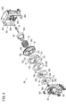
- 4 is an exploded perspective view showing the components of the rotary valve of FIG. 3;
- FIG. 5 is a perspective cross-sectional view of a rotating manifold and a frame.
- FIG. 6 is a perspective cross-sectional view of the stationary manifold and port members;
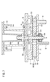
- FIG. 7 is a cross-sectional view of the rotating manifold pressed against the stationary manifold.
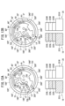
- 8A is an explanatory diagram showing the connection state of each port at the initial position of the rotary manifold, and FIG.
- FIG. 8B is an explanatory diagram showing the connection state of each port at the position where the rotary manifold is rotated by 20°.
- 9A is an explanatory diagram showing the connection state of each port when the rotary manifold is rotated by 40°
- FIG. 9B is an explanatory diagram showing the connection state of each port when the rotary manifold is rotated by 60°. be.
- 10A is an explanatory diagram showing the connection state of each port when the rotary manifold is rotated by 80°
- FIG. 10B is an explanatory diagram showing the connection state of each port when the rotary manifold is rotated by 160°. be.
- FIG. 11A is an explanatory diagram showing the connection state of each port when the rotary manifold is rotated by 190°
- FIG. 11B is an explanatory diagram showing the connection state of each port when the rotary manifold is rotated by 210°. be
- FIG. 12A is an explanatory diagram showing the connection state of each port when the rotary manifold is rotated by 230°
- FIG. 12B is an explanatory diagram showing the connection state of each port when the rotary manifold is rotated by 250°. be
- FIG. 13A is an explanatory diagram showing the connection state of each port at the position where the rotary manifold is rotated by 330°
- FIG. 13B is an explanatory diagram showing the connection state of each port at the position where the rotary manifold is rotated by 360°. be.
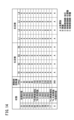
- FIG. 14 is a table showing the operation of the foot pump due to rotation of the rotary manifold shown in FIGS. 8A-13B.
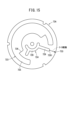
- FIG. 15 is a plan view of a rotary manifold according to a modification of the embodiment;
- the massage system 10 includes a foot pump 12, an air supply controller 14, and a tube 16, as shown in FIG.
- the foot pump 12 has a left sleeve 18 that is worn on the patient's left leg and a right sleeve 20 that is worn on the patient's right leg.
- the left sleeve 18 has a sleeve sheet 22L that can be wrapped around the left leg.
- the foot pump 12 of this embodiment is a foot calf pump. Therefore, the sleeve sheet 22L is used by being wrapped around the sole and the lower leg.
- the sleeve sheet 22L has hook-and-loop fasteners 24 on its side ends 220 for fixing while wrapped around the leg.
- the sleeve sheet 22L has four bags 221L, 222L, 223L and 224L that are inflated when air is supplied.
- the bag 221L is located at the most distal end of the sleeve sheet 22L.
- the distal end of the sleeve sheet 22L means a direction or a portion in which the sleeve sheet 22L is worn at a position relatively distant from the trunk when the patient wears the sleeve sheet 22L.
- proximal side of the sleeve sheet 22L means a direction or a portion in which the sleeve sheet 22L is worn at a position relatively closer to the trunk when the patient wears the sleeve sheet 22L.
- the bag 221L comes into contact with the sole and presses the sole.
- Bag 222L is positioned adjacent to and proximal to bag 221L. The bag 222L comes into contact with the ankle and compresses the ankle.
- the bag 223L is located proximal to and adjacent to the bag 222L.
- the bag 224L is arranged most proximally of the sleeve sheet 22L.
- the bags 223L and 224L press the lower leg of the left leg.
- Four tubes 16 are connected to each of the bags 221L-224L to individually supply air to the bags 221L-224L. That is, four tubes 16 are connected to the left sleeve 18 .
- the right sleeve 20 has the same structure as the left sleeve 18 except that it is formed symmetrically with the left sleeve 18 .
- the same numerals and the suffix R are added to the same structure as the left sleeve 18, and the explanation thereof is omitted.
- the tubes 16 of the left sleeve 18 and right sleeve 20 are connected to the tubes 16 of the air supply controller 14 via tube connectors 26 .
- the air supply controller 14 distributes and supplies compressed air to the four bags 221L to 224L of the left sleeve 18 and the four bags 221R to 224R of the right sleeve 20 at predetermined timings.
- the air supply controller 14 includes a rotary valve 28, an air pump 30, pressure regulating valves 32L and 32R, a pressure relief valve 34, a control section 36, a display section 38, and a communication section 40. , a temperature sensor 42 , a battery 44 , an audio output section 46 and a power supply circuit 48 .
- the air pump 30 supplies compressed air for inflating the bags 221L-224R of the left sleeve 18 and the right sleeve 20.
- Air pump 30 is connected to stationary manifold 70 (see FIG. 3) of rotary valve 28 .
- the stationary manifold 70 has an air flow path 50 .
- the air flow path 50 communicates the air pump 30 , the pressure relief valve 34 and the pressure sensor 54 inside the rotary valve 28 .
- a rotary valve 28 distributes compressed air to the plurality of tubes 16 in a predetermined order.
- the rotary valve 28 has a fixed manifold 70 and a rotary manifold 72, and connects the plurality of tubes 16 to the exhaust port at predetermined timings. Details of the rotary valve 28 will be described later.
- the pressure regulating valve 32L is a two-way valve that switches between an open state in which the regulating flow path 52L communicating with the left sleeve 18 is open to the atmosphere and a closed position in which the regulating flow path 52L is blocked from opening to the atmosphere.
- the adjustment channel 52L branches off from the air channel leading to the bag 223L of the left sleeve 18.
- One end of the pressure regulating valve 32L is connected to the regulating flow path 52L, and the other end of the pressure regulating valve 32L is open to the atmosphere.
- the pressure regulating valve 32L operates to switch between the open state and the closed state so that the pressure of the compressed air supplied to the bag 223L becomes a predetermined value.
- the pressure control valve 32L applies a predetermined pressure to the bag 223L of the left sleeve 18 at a predetermined timing, thereby making it possible to detect the state of blood flow in the left leg.
- the pressure regulating valve 32R is connected to the regulating flow path 52R that communicates with the right sleeve 20.
- the pressure regulating valve 32R is similar to the pressure regulating valve 32L except that it is connected to the bag 223R of the right sleeve 20.
- the pressure control valve 32R applies a predetermined pressure to the bag 223R, thereby making it possible to detect the state of blood flow in the right leg.
- the pressure relief valve 34 releases the compressed air inside the air channel 50 when the pressure in the air channel 50 exceeds a predetermined value.
- the pressure relief valve 34 prevents excessive pressure build-up in the air flow path 50 .
- the control section 36 controls each section of the air supply controller 14 .
- Control unit 36 includes a pressure sensor 54 .
- a pressure sensor 54 is connected to the air flow path 50 and detects the pressure of the compressed air in the air flow path 50 .
- the display unit 38 includes, for example, a touch panel. The display unit 38 receives input of operating conditions of the air supply controller 14 and displays the operating state of the massage system 10 .
- the communication unit 40 includes, for example, an NFC (Near Field Communication) antenna.
- a temperature sensor 42 measures the temperature of the compressed air.
- a battery 44 provides the power necessary to operate the air delivery controller 14 .
- the audio output unit 46 notifies the information about the operation and the information such as the alarm by voice.
- the power supply circuit 48 is connected to a commercial power supply through a power cord.
- a power supply circuit 48 supplies DC power at a voltage required for operation of the air supply controller 14 .
- the rotary valve 28 includes a fixed manifold 70, a rotary manifold 72, a port member 58 that supports the fixed manifold 70, and a frame 60 that rotatably holds the rotary manifold 72.
- the port member 58 has a rectangular plate member 581 .
- a plurality of ports 62 protrude from the first surface 582 of the plate member 581 .
- Port 62 has a tubular shape.
- port member 58 has eleven ports 62 .
- the port 62 has an air supply port 64, a pressure sensor port 65, a forced exhaust port 66, connection ports 621L-624L, and connection ports 621R-624R.
- the air supply port 64 is connected to the air pump 30 and introduces compressed air for driving the left sleeve 18 and the right sleeve 20 .
- Pressure sensor port 65 is connected to pressure sensor 54 via a tube.
- Forced exhaust port 66 is connected to pressure relief valve 34 via tubing.
- connection port 621L is connected to the bag 221L
- connection port 622L is connected to the bag 222L
- connection port 623L is connected to the bag 223L
- connection port 624L is connected to the bag 224L
- the connection port 621R is connected to the bag 221R
- the connection port 622R is connected to the bag 222R
- the connection port 623R is connected to the bag 223R
- the connection port 624R is connected to the bag 224R.
- the port 62 has a channel 625 that penetrates the plate member 581 in the thickness direction.
- a channel 625 of the port 62 opens to the second surface 583 of the plate member 581 .
- the port member 58 further has a drive motor 68 and a stationary manifold 70.
- the drive motor 68 is fixed to the first surface 582 of the plate member 581 .
- the drive motor 68 has a drive shaft 681 extending in the thickness direction of the plate member 581 .
- the plate member 581 has a notch hole 584 in a portion through which the drive shaft 681 passes. A cutout hole 584 allows rotation of the drive shaft 681 .
- the drive motor 68 rotates the drive shaft 681 around the longitudinal axis of rotation of the drive shaft 681 .
- a driving gear 682 is formed on the outer peripheral portion of the driving shaft 681 .
- the drive gear 682 meshes with a rotating gear 76 (see FIG. 4), which will be described later.
- Drive motor 68 rotates rotary gear 76 through drive gear 682 .
- Drive motor 68 is electrically connected to controller 36 through a cable (not shown).
- the drive motor 68 is rotated by the drive current of the controller 36 .
- the drive motor 68 forms part of the drive mechanism that rotates the rotary manifold 72 .
- the fixed manifold 70 has a disk-like shape and has an adhesive surface 701 and a first sliding surface 702 .
- the fixed manifold 70 is joined to the plate member 581 with the adhesive surface 701 facing the second surface 583 of the plate member 581 .
- a seal member 71 is arranged between the fixed manifold 70 and the plate member 581 as shown in FIG.
- the sealing member 71 is, for example, a double-sided adhesive tape, and fixes the stationary manifold 70 to the second surface 583 of the plate member 581 .
- the seal member 71 seals the gap between the adhesive surface 701 and the second surface 583 to prevent leakage of compressed air from the gap.
- the sealing member 71 has a through hole 703 of the bonding surface 701 of the fixed manifold 70, a fixing hole 704, a shaft hole 705, and an opening 71a having the same shape as the air flow path 50, which will be described later.
- the fixed manifold 70 further has a plurality of through holes 703, a plurality of fixed holes 704, an axial hole 705, and an air flow path 50.
- the through-holes 703 pass through the stationary manifold 70 in the thickness direction.
- the stationary manifold 70 has eleven through holes 703.
- the through holes 703 are arranged at positions corresponding to the plurality of connection ports 621L to 624L, 621R to 624R and the air flow path 50, respectively.
- the fixing holes 704 are non-through holes formed in the bonding surface 701 of the fixing manifold 70 .
- the fixed hole 704 prevents rotation of the fixed manifold 70 by engaging with a projection 585 protruding from the plate member 581 .
- the shaft hole 705 is positioned at the center of the fixed manifold 70 and is provided in the fixed manifold 70 alone.
- the shaft hole 705 penetrates through the fixed manifold 70 in the thickness direction.
- the shaft hole 705 allows an axial shaft 74, which will be described later, to pass therethrough.
- the plate member 581 has a bearing 586 communicating with the shaft hole 705 .
- the bearing 586 rotatably supports the tip of the shaft 74 .
- the first sliding surface 702 of the fixed manifold 70 serves as a sliding surface with the second sliding surface 721 (see FIG. 4) of the rotary manifold 72 .
- the fixed manifold 70 is made of a material such as metal, ceramic, resin, or the like that is difficult to deform.
- An aluminum alloy is suitable as a material for the stationary manifold 70 because it is excellent in formability, has sufficient strength, and is light in weight.
- the air flow path 50 is configured by non-penetrating grooves formed in the adhesive surface 701 of the fixed manifold 70 in the thickness direction.
- the air flow path 50 has an arc-shaped groove 501 having a second radius and branch-shaped grooves 502 and 503 branching outward from the arc-shaped groove 501 .
- Arcuate groove 501 communicates with pressure sensor port 65 located at the second radius.
- branch groove 502 extends to a third radius and is connected to insufflation port 64 located at the third radius.
- Branch groove 503 extends to a first radius and is connected to forced exhaust port 66 located at the first radius.
- the arc-shaped groove 501 is connected to the through holes 703a and 703b for supplying air.
- the frame 60 has a frame member 601, a rotating manifold 72, an axial shaft 74, a rotating gear 76, and a pressing member 78 (coil spring).
- the frame member 601 has a support plate 602 arranged parallel to the plate member 581 and four pillars 603 extending from the support plate 602 toward the plate member 581 .
- the struts 603 of the frame 60 come into contact with the plate member 581 .
- Post 603 is secured to port member 58 by screwing.
- the support plate 602 has a first column portion 604 and a second column portion 605 protruding toward the plate member 581 .
- the first column portion 604 has a bearing 606 at its tip.
- the first column 604 rotatably supports the proximal end of the shaft 74 through bearings 606 .
- the second column portion 605 has a bearing 607 at its tip.
- the second post 605 rotatably supports the end of a drive shaft 681 extending from the drive motor 68 (see FIG. 6).
- the rotary manifold 72 has a disk-like shape and has a second sliding surface 721 and a fitting surface 722 .
- Rotating manifold 72 is made of the same material as stationary manifold 70 .
- the rotating manifold 72 serves as a sliding surface on which the second sliding surface 721 faces the first sliding surface 702 of the fixed manifold 70 and slides thereon.
- the second sliding surface 721 has first communication grooves 723 and second communication grooves 724 that selectively allow the plurality of ports 62 to communicate.
- the first communication groove 723 includes a first arcuate groove 725 having a first radius formed near the outer circumference of the rotary manifold 72 and a plurality of first branch grooves extending radially inward from the first arcuate groove 725. 726 and .
- Exhaust holes 727 are formed at one end and the other end of the first arcuate groove 725 .
- the exhaust hole 727 penetrates the rotary manifold 72 in the thickness direction and opens to the fitting surface 722 .
- the exhaust hole 727 is open to the atmosphere and constitutes the exhaust port of this embodiment. Accordingly, the first communication groove 723 opens some of the ports 62 to the atmosphere to discharge compressed air from the bags 221L to 224L and 221R to 224R.
- the second communication groove 724 includes a second arc-shaped groove 728 spaced apart from the first communication groove 723 on the inner peripheral side, and a plurality of second arc-shaped grooves 728 extending radially outward from the second arc-shaped groove 728 . It has a bifurcated groove 729 .
- the second arcuate groove 728 is formed with a second radius that allows communication with the through holes 703a and 703b.
- the second branch grooves 729 extend to radial positions where they can be connected to the connection ports 621L-624L, 621R-624R. Therefore, the second communication groove 724 supplies compressed air to the connection ports 621L to 624L and 621R to 624R.
- the first communication groove 723 and the second communication groove 724 are spaced apart by a predetermined close distance or more to prevent leakage of compressed air.
- the rotary manifold 72 has a lubricating layer 80 on the second sliding surface 721 .
- the lubricating layer 80 prevents wear with the first sliding surface 702 of the stationary manifold 70 .
- the lubricating layer 80 blocks the gap between the second sliding surface 721 and the first sliding surface 702, thereby preventing compressed air from leaking.
- the lubricating layer 80 of the present embodiment is composed of a lubricating and airtight resin tape 82 such as polyethylene resin.
- the resin tape 82 is bonded to the second sliding surface 721 of the rotary manifold 72 with an adhesive.
- the resin tape 82 has grooves of the same shape as the first communication groove 723 and the second communication groove 724 of the second sliding surface 721 .
- the resin tape 82 has a thickness of about 0.4 mm.
- the resin tape 82 may be adhered to the first sliding surface 702 side of the stationary manifold 70 .
- the resin tape 82 has openings at positions corresponding to the ports 62 .
- the lubricating layer 80 is not limited to the resin tape 82, and may be formed of a lubricant such as grease or oil.
- the lubricating layer 80 may be formed by depositing a resin layer on the resin tape 82 .
- the rotary manifold 72 has an axial hole 720 through which the axial shaft 74 is inserted at its center.
- the shaft hole 720 penetrates through the rotary manifold 72 in the thickness direction.
- Rotating manifold 72 is connected to axial shaft 74 at axial hole 720 .
- the rotary manifold 72 has a recess 730 in the mating surface 722 .
- Three recesses 730 are provided at intervals of about 120° in the circumferential direction.
- the recess 730 fits with the projection 761 of the rotating gear 76 .
- the recess 730 and the projection 761 integrate the rotary manifold 72 and the rotary gear 76 in the rotational direction.
- an outer peripheral groove 731 is formed in the outer peripheral portion of the rotary manifold 72 .
- the outer peripheral groove 731 is a groove extending in the axial direction and is fitted with the pin 762 of the rotating gear 76 .
- the outer peripheral groove 731 and the pin 762 prevent the rotating manifold 72 and the resin tape 82 from being dislocated and rattling during rotation.
- the rotary gear 76 is arranged on the fitting surface 722 of the rotary manifold 72 .
- the rotary gear 76 is formed in a disc shape.
- the rotary gear 76 has an axial hole 763 in which the axial shaft 74 is fitted in the center.
- the rotary gear 76 is supported by the axial shaft 74 and rotates around the axis of the axial shaft 74 .
- the rotating gear 76 has a gear 764 on its outer periphery. Gear 764 rotates in mesh with drive gear 682 (see FIG. 6).
- the rotating gear 76 rotates by receiving a rotational force from the drive gear 682 .
- the rotary gear 76 has a first seat portion 765 on the surface facing the support plate 602 .
- the first seat portion 765 has a groove-like shape that can accommodate one end of the pressing member 78 .
- the rotary gear 76 has three projections 761 projecting toward the rotary manifold 72 . Further, the rotary gear 76 has three pins 762 fitted in the outer peripheral grooves 731 of the rotary manifold 72 on its outer periphery.
- the pressing member 78 is arranged adjacent to the rotating gear 76 .
- One end of the pressing member 78 contacts the rotating gear 76 .
- the other end of the pressing member 78 abuts on the holding portion 84 .
- the pressing member 78 generates an urging force that presses the rotary manifold 72 against the stationary manifold 70 .
- the urging force of the pressing member 78 is obtained by bringing the second sliding surface 721 of the rotary manifold 72 and the first sliding surface 702 of the stationary manifold 70 into close contact with each other via the lubricating layer 80 (see FIG. 7). prevent compressed air from leaking along the
- the holding portion 84 is a tubular member fixed to the support plate 602 .
- the holding portion 84 has a groove-shaped second seat portion 841 that accommodates the other end of the pressing member 78 in a portion adjacent to the support plate 602 .
- the second seat portion 841 prevents the pressing member 78 from coming off.
- the shaft 74 is arranged at the center of rotation of the rotary manifold 72 and rotary gear 76 .
- the axial shaft 74 has a substantially cylindrical shape. As shown in FIG. 5, one end of the shaft 74 is rotatably supported by the bearing 606 of the first column 604. As shown in FIG. Axial shaft 74 is joined to rotating gear 76 and rotates integrally with rotating gear 76 .
- the axial shaft 74 passes through the central portions of the rotary manifold 72 and the rotary gear 76 . Further, the shaft 74 passes through the shaft hole 705 of the fixed manifold 70 and is rotatably supported by the bearing 586 of the plate member 581 .
- the first arcuate groove 725 of the first communication groove 723 is formed at a first radial position from the rotation center of the rotary manifold 72 in the radial direction.
- the first arcuate groove 725 is formed in a range of 0° to 260° in the circumferential direction.
- Exhaust holes 727 are formed at both ends of the first arcuate groove 725 .
- the exhaust holes 727 are respectively provided at the 0° position and the 260° position in FIG. 8A.
- the first communicating groove 723 is open to the atmosphere through an exhaust hole 727 .
- a first branched groove 726 branched from the first communication groove 723 is formed in the range of about 40° to 80° and about 210° of the first arcuate groove 725 .
- a first branched groove 726 in the vicinity of 40° to 80° is formed wide in the circumferential direction.
- the first branched grooves 726 near 210° have a width in the circumferential direction narrower than the circumferential spacing of the through holes 703 .
- First branched groove 726 extends to a third radius that is less than the first radius.
- the first branch groove 726 can communicate with the connection port 623L or the connection port 623R arranged at the third radius.
- the second arcuate groove 728 of the second communication groove 724 is positioned at the second radius from the rotation center of the rotary manifold 72.
- the second radius is a smaller radius than the first and third radii.
- Through holes 703a and 703b are arranged at a second radius. Therefore, the second arcuate groove 728 can communicate with the air flow path 50 via the through hole 703a or the through hole 703b.
- the second arcuate groove 728 is formed in the range of 190° to 0° in FIG. 8A.
- Second branch grooves 729 branching radially outward from the second arc-shaped groove 728 are formed near 240° and 340° in FIG. 8A.
- the two second branched grooves 729 have a width in the circumferential direction narrower than the circumferential interval between the most adjacent through holes 703 .
- a second branched groove 729 near 240° extends to a third radius.
- a second branched groove 729 near 340° extends to the first radius.
- the positions of the first communication groove 723 and the second communication groove 724 of the rotary manifold 72 are displaced as the rotary manifold 72 rotates. Accordingly, the circumferential positions of the first branched groove 726 and the second branched groove 729 also change.
- the circumferential position of the rotary manifold 72 may be detected by an arranged position sensor.
- the position sensor for example, a photoelectric reflection type detector can be used. In this case, the photoelectric reflection type detector is arranged at a predetermined position of the rotary valve 28 .
- the rotary manifold 72 has a detected part arranged at a predetermined position.
- This method detects the position of the rotating manifold 72 in the circumferential direction by detecting the position of the detected part with a detector. Also, other known rotation detection methods can be applied to detect the circumferential position of the rotary manifold 72 . Also, as a method that does not use a position sensor, there is a method that uses a sequencer. In this method, the sequencer calculates the position of the rotary manifold 72 in the circumferential direction by counting the number of motor pulses to determine the amount of change from the initial position.
- the stationary manifold 70 has six through holes 703 at the first radius, two through holes 703 at the third radius, and two through holes 703 at the second radius.
- the through-hole 703 a at the position of 0° of the second radius and the through-hole 703 b at the position of 170° of the second radius communicate with the air supply port 64 via the air flow path 50 .
- the through hole 703 at the position of 40° of the third radius communicates with the connection port 623R
- the through hole 703 at the position of 210° of the third radius communicates with the connection port 623L.
- the through-hole 703 at the position of 0° of the first radius communicates with the connection port 621R, the through-hole 703 at the position of 20° of the first radius communicates with the connection port 622R, and the through-hole 703 at the position of 60° of the first radius communicates with the connection port 621R.
- Hole 703 communicates with connection port 624R.
- the through-hole 703 located at 170° of the first radius communicates with the connection port 621L
- the through-hole 703 located at 190° of the first radius communicates with the connection port 622L, and communicates with the connection port 622L at the position of 230° of the first radius.
- the through hole 703 communicates with the connection port 624L.
- FIGS. 8A-13B The operations of the left sleeve 18 and the right sleeve 20 accompanying the rotation of the rotary manifold 72 will be described below with reference to FIGS. 8A to 13B.
- 8A-13B the inflated portions of left sleeve 18 and right sleeve 20 are indicated in color.
- the table of FIG. 14 also shows the operation of the foot pump 12 due to the rotation of the rotary manifold 72 shown in FIGS. 8A-13B.
- L1 to L4 and R1 to R4 are denoted by L1 to L4 and R1 to R4 in FIGS. 8A to 13B.
- L1, L2, L3, and L4 indicate communication with connection ports 621L, 622L, 623L, and 624L, respectively.
- R1, R2, R3, and R4 indicate communication with connection ports 621R, 622R, 623R, and 624R, respectively.
- FIG. 8A shows the initial position of the rotary manifold 72, and all the connection ports 621L to 624L, 621R to 624R overlap the first communication grooves 723.
- the rotary manifold 72 rotates counterclockwise at a constant speed when viewed from the support plate 602 side. As shown in FIG. 8B, when the rotary manifold 72 rotates 20° from the initial position, the second branch groove 729 of the second communication groove 724 communicates with the connection port 621R. Also, the second communication groove 724 allows the second arcuate groove 728 to communicate with the through hole 703b. Therefore, the connection port 621 ⁇ /b>R communicates with the air supply port 64 through the second communication groove 724 and the air flow path 50 . As a result, compressed air is supplied to the bag 221R of the right sleeve 20 to inflate the bag 221R.
- the second branch groove 729 communicates with the connection port 622R as shown in FIG. 9A.
- the second communication groove 724 communicates the connection port 622R with the through hole 703b.
- compressed air is supplied to the bag 222R through the through hole 703b, and the bag 222R is inflated.
- the connection port 621R is closed by the sliding surfaces of the fixed manifold 70 and the rotary manifold 72. As shown in FIG. Therefore, the bag 221R is kept inflated.
- the width of the second branch groove 729 is narrower than the circumferential intervals of the plurality of connection ports 621L to 624L and 621R to 624R. Therefore, while the communication destination of the second communication groove 724 is switched from the connection port 621R to the connection port 622R, the connection port 621R and the connection port 622R do not communicate with each other. Therefore, backflow of compressed air from the bag 221R to the bag 222R can be prevented. Thereby, the rotary valve 28 facilitates pressure control of the plurality of bags 221L-224L, 221R-224R.
- the second branch groove 729 communicates with the connection port 623R as shown in FIG. 9B. This inflates the bag 223R.
- the bags 221R, 222R are kept inflated.
- the massage system 10 promotes the return of venous blood in the patient's lower extremities by gradually moving from the distal side to the proximal side of the site where the patient's body is pressed.
- the first arcuate groove 725 of the first communication groove 723 communicates with the connection port 621R.
- the first communication groove 723 exhausts compressed air from the bag 221R.
- the bag 221R is contracted.
- Further rotation of the rotary manifold 72 causes the first arcuate groove 725 to communicate with the connection port 622R.
- the first arcuate groove 725 communicates with the connection port 624R.
- the bags 221R, 222R, and 224R of the right sleeve 20 are evacuated and contracted in this order.
- connection port 623R is located at the third radius, the bag 223R remains inflated. 10B, the bag 223R is connected to the pressure sensor 54 of FIG. Therefore, the air supply controller 14 measures the pressure supplied to the bag 223R.
- the controller 36 detects changes in sleeve pressure associated with venous flow based on pressure changes.
- the control unit 36 estimates the time from the detected pressure change until the blood flow returns to the vein.
- the control unit 36 corrects the cycle speed based on the time required for blood flow to return to the vein.
- the first branch groove 726 communicates with the connection port 623R as shown in FIG. 11A.
- compressed air is discharged from the bag 223R.
- All the bags 221R to 224R of the right sleeve 20 are thereby contracted.
- the second branch groove 729 communicates with the connection port 621L. Thereby, the bag 221L of the left sleeve 18 is inflated.
- the second branch groove 729 communicates with the connection port 622L as shown in FIG. 11B. This inflates the bag 222L.
- the connection port 621L is closed by the sliding surface. Therefore, the bag 221L remains inflated.
- the second branch groove 729 communicates with the connection port 623L as shown in FIG. 12A. This inflates the bag 223L. Also, the connection ports 621L and 622L are closed by the sliding surface. Therefore, the bags 221L and 222L remain inflated.
- the second branch groove 729 communicates with the connection port 624L as shown in FIG. 12B. This inflates the bag 224L. All bags 221L-224L of left sleeve 18 are inflated.
- connection ports 621L, 622L, and 624L communicate with the first communication groove 723 in this order while the rotary manifold 72 rotates from the initial position to 330°.
- the bags 221L, 222L and 224L contract in this order.
- the controller 36 measures the pressure change of the bag 223L and corrects the operating conditions.
- connection port 623L communicates with the first branch groove 726 of the first communication groove 723.
- the bag 223L is evacuated and returns to the initial state.
- the rotary valve 28 causes the rotary manifold 72 to rotate at a constant speed.
- the massage system 10 repeatedly performs the compression operation of the foot pump 12 .
- the massage system 10 can prevent the formation of blood clots by promoting blood flow in the patient's feet.
- this modification relates to a modification of the rotary valve 28.
- a rotary manifold 72A of this modification has a larger diameter than the rotary manifold 72 shown in FIG.
- the first communication groove 723 has one wider first branch groove 726 .
- the first branched groove 726 extends over most of the circumferential range of the first arcuate groove 725 of the first communicating groove 723 .
- the resin tape 82 of this modified example has a thickness of 0.12 mm, which is thinner than the resin tape 82 of the embodiment (thickness of about 0.4 mm).
- the rotary manifold 72A of this modified example the proportion of the area occupied by the first arcuate grooves 725 and the first branch grooves 726 is increased. Therefore, the rotary manifold 72A can improve the surface pressure on the contact portion between the first sliding surface 702 and the second sliding surface 721, and can prevent leakage of compressed air. Further, by increasing the diameter of the rotary manifold 72A, it is possible to increase the distance between the tip 7291 of the second branch groove 729, which is the main leakage path of the compressed air, and the outer peripheral portion 733 of the rotary manifold 72A. Leakage of compressed air through the sliding surface can be suppressed.
- the massage system 10, air supply controller 14 and rotary valve 28 of this embodiment have the following effects.
- This embodiment is a rotary valve 28 that distributes fluid to a plurality of bags 221L-224L, 221R-224R of the foot pump 12, and includes a connection port to which a tube 16 extending from the foot pump 12 is connected and an air pump 30.
- a port member 58 having an air supply port 64 to which a tube is connected, a through hole 703 arranged adjacent to the port member 58 and penetrating in the thickness direction to communicate with the connection port or the air supply port 64, and a port.
- a fixed manifold 70 having a first sliding surface 702 formed on the opposite side of the member 58 and having a through hole 703 open therein;
- a rotating manifold 72 that has a sliding surface 721 and rotates with respect to the fixed manifold 70, a pressing member 78 that presses the rotating manifold 72 toward the fixed manifold 70, and a rotating mechanism (for example, a rotating mechanism) that rotates the rotating manifold 72.
- the second sliding surface 721 includes a first arcuate groove 725 formed at a first radius from the rotation center of the rotary manifold 72, and an exhaust pipe connected to the first arcuate groove 725.
- first communicating groove 723 having a hole 727
- second communicating groove 724 having a second arcuate groove 728 formed at a second radius different from the first radius from the center of rotation.
- at least one first branch groove 726 branched from the first arcuate groove 725 and extending in the radial direction
- second communication groove 724 branched from the second arcuate groove 728 and extending in the radial direction. It has a second branch groove 729 .
- the massage system 10 can be made smaller and lighter.
- air is supplied to some bags and blood flow in veins is detected while other bags are can be evacuated simultaneously.
- the second communicating groove 724 may have a plurality of second branched grooves 729, and the plurality of second branched grooves 729 may have different lengths in the radial direction. According to this rotary valve 28, it is possible to change the timing of inflation or deflation of a specific bag by changing the radial installation position of the connection port connected to the specific bag.
- At least one second branch groove 729 may have a circumferential width narrower than the circumferential interval of the through holes 703 . According to this rotary valve 28, it is possible to prevent the adjacent through holes 703 from communicating with each other when using the second branch groove 729 for supplying air. As a result, when switching the air supply destination, it is possible to prevent a phenomenon in which the compressed air of another bag flows backward and the pressure of the other bag decreases. Therefore, according to this rotary valve 28, the pressure controllability of the bags 221L to 224L and 221R to 224R is excellent.
- the air supply port 64 is arranged at the second radius
- the connection port is arranged at the first radius or a third radius between the first radius and the second radius
- the connection port is the center of rotation. may be spaced apart in the circumferential direction of the According to this rotary valve 28 , the air supply destination can be sequentially switched with the rotation of the rotary manifold 72 through the branch groove of the second communication groove 724 with respect to the connection port.
- connection ports may be arranged in the circumferential direction so that air is supplied in order from the bag on the distal end side of the foot pump 12 .
- venous blood can be sent out from the distal end of the patient's leg toward the trunk of the patient, so the occurrence of thrombus can be effectively suppressed.
- the space between the first sliding surface 702 of the fixed manifold 70 and the second sliding surface 721 of the rotating manifold 72 is airtightly sealed, and the first sliding surface 702 and the second sliding surface 721 It may have a lubricating layer 80 that lubricates the According to this rotary valve 28, it is possible to prevent leakage of air through the sliding surface and wear of the sliding surface.
- the lubricating layer 80 may be a resin tape 82 attached to the first sliding surface 702 or the second sliding surface 721 . According to this rotary valve 28, it is possible to maintain lubricity and airtightness over a longer period of time than when using oil, grease, or the like, and is highly reliable.
- the air supply controller 14 of this embodiment has an air pump 30 that supplies compressed air and the rotary valve 28 described above. Since the air supply controller 14 has the rotary valve 28, the device configuration can be reduced in size and weight.
- the massage system 10 of this embodiment includes a foot pump 12 having a plurality of bags, and an air supply controller 14 for supplying and discharging compressed air to and from the plurality of bags of the foot pump 12. of rotary valves 28 are provided. Since the massage system 10 has the rotary valve 28, the device configuration can be reduced in size and weight.
Landscapes
- Health & Medical Sciences (AREA)
- Dermatology (AREA)
- Epidemiology (AREA)
- Pain & Pain Management (AREA)
- Physical Education & Sports Medicine (AREA)
- Rehabilitation Therapy (AREA)
- Life Sciences & Earth Sciences (AREA)
- Animal Behavior & Ethology (AREA)
- General Health & Medical Sciences (AREA)
- Public Health (AREA)
- Veterinary Medicine (AREA)
- Massaging Devices (AREA)
Priority Applications (1)
| Application Number | Priority Date | Filing Date | Title |
|---|---|---|---|
| JP2023556586A JPWO2023074717A1 (https=) | 2021-11-01 | 2022-10-26 |
Applications Claiming Priority (2)
| Application Number | Priority Date | Filing Date | Title |
|---|---|---|---|
| JP2021-178610 | 2021-11-01 | ||
| JP2021178610 | 2021-11-01 |
Publications (1)
| Publication Number | Publication Date |
|---|---|
| WO2023074717A1 true WO2023074717A1 (ja) | 2023-05-04 |
Family
ID=86157948
Family Applications (1)
| Application Number | Title | Priority Date | Filing Date |
|---|---|---|---|
| PCT/JP2022/039815 Ceased WO2023074717A1 (ja) | 2021-11-01 | 2022-10-26 | ロータリーバルブ、送気コントローラ及びマッサージシステム |
Country Status (2)
| Country | Link |
|---|---|
| JP (1) | JPWO2023074717A1 (https=) |
| WO (1) | WO2023074717A1 (https=) |
Citations (4)
| Publication number | Priority date | Publication date | Assignee | Title |
|---|---|---|---|---|
| JPH0356434U (https=) * | 1989-10-05 | 1991-05-30 | ||
| JPH09313557A (ja) * | 1996-05-31 | 1997-12-09 | Megoafeck Ind Measuring Instr | 空圧マッサージ装置 |
| JP2012011065A (ja) * | 2010-07-02 | 2012-01-19 | Nitto Kohki Co Ltd | 空気圧マッサージ器の空気分配バルブ |
| US20150131022A1 (en) * | 2013-11-13 | 2015-05-14 | Shenzhen China Star Optoelectronics Technology Co. Ltd. | Multiple display monitor |
-
2022
- 2022-10-26 WO PCT/JP2022/039815 patent/WO2023074717A1/ja not_active Ceased
- 2022-10-26 JP JP2023556586A patent/JPWO2023074717A1/ja active Pending
Patent Citations (4)
| Publication number | Priority date | Publication date | Assignee | Title |
|---|---|---|---|---|
| JPH0356434U (https=) * | 1989-10-05 | 1991-05-30 | ||
| JPH09313557A (ja) * | 1996-05-31 | 1997-12-09 | Megoafeck Ind Measuring Instr | 空圧マッサージ装置 |
| JP2012011065A (ja) * | 2010-07-02 | 2012-01-19 | Nitto Kohki Co Ltd | 空気圧マッサージ器の空気分配バルブ |
| US20150131022A1 (en) * | 2013-11-13 | 2015-05-14 | Shenzhen China Star Optoelectronics Technology Co. Ltd. | Multiple display monitor |
Also Published As
| Publication number | Publication date |
|---|---|
| JPWO2023074717A1 (https=) | 2023-05-04 |
Similar Documents
| Publication | Publication Date | Title |
|---|---|---|
| US6062244A (en) | Fluidic connector | |
| CA2866698C (en) | Deep vein thrombosis ("dvt") and thermal/compression therapy systems, apparatuses and methods | |
| US9168197B2 (en) | Vascular compression system | |
| US7810519B2 (en) | Fluid conduit connector apparatus | |
| CN101312703B (zh) | 防止深静脉血栓的装置 | |
| US12514777B2 (en) | Controller for an extremity hyperbaric device | |
| JP4602996B2 (ja) | 流体導管コネクタ装置 | |
| JP6929926B2 (ja) | 磁力駆動型動静脈アクセスバルブシステム及びそれに関連する方法 | |
| US20120209153A1 (en) | Deep vein thrombosis therapy device | |
| WO2003041621A8 (en) | Compression garment for selective application of treatment of lymphedema and related illnesses manifested at various location of the body | |
| AU2006252009A1 (en) | Compression apparatus | |
| KR20070048196A (ko) | 항문 개폐장치 | |
| WO2023074717A1 (ja) | ロータリーバルブ、送気コントローラ及びマッサージシステム | |
| AU2010270547B2 (en) | Blood-pumping device | |
| JP2021510343A (ja) | 血液透析静脈準備方法 | |
| US3167067A (en) | Rotary distributor for pressure cuff tourniquets | |
| JP2002518136A (ja) | 高圧駆動システム | |
| US8118572B2 (en) | Peristaltic pump tubing with stopper and cooperative roller assembly housing having no moving parts | |
| CN205683114U (zh) | 便携式自动止血装置 | |
| EP0879982A3 (de) | Drehkupplung, Feuerwehrschlauch-Kupplung und Schlauch-Klemmvorrichtung | |
| JP3975807B2 (ja) | 生体情報計測装置 | |
| US20260083620A1 (en) | Pneumatic compression device | |
| JP4027505B2 (ja) | エアマッサージ器 | |
| BRPI0503972A (pt) | esfigmomanÈmetro aplicável a membros de diferentes medidas | |
| CN219803958U (zh) | 足部用洗浴装置 |
Legal Events
| Date | Code | Title | Description |
|---|---|---|---|
| 121 | Ep: the epo has been informed by wipo that ep was designated in this application |
Ref document number: 22887042 Country of ref document: EP Kind code of ref document: A1 |
|
| WWE | Wipo information: entry into national phase |
Ref document number: 2023556586 Country of ref document: JP |
|
| NENP | Non-entry into the national phase |
Ref country code: DE |
|
| 122 | Ep: pct application non-entry in european phase |
Ref document number: 22887042 Country of ref document: EP Kind code of ref document: A1 |