WO2023074529A1 - 通信方法 - Google Patents
通信方法 Download PDFInfo
- Publication number
- WO2023074529A1 WO2023074529A1 PCT/JP2022/039136 JP2022039136W WO2023074529A1 WO 2023074529 A1 WO2023074529 A1 WO 2023074529A1 JP 2022039136 W JP2022039136 W JP 2022039136W WO 2023074529 A1 WO2023074529 A1 WO 2023074529A1
- Authority
- WO
- WIPO (PCT)
- Prior art keywords
- cell
- mbs
- communication method
- paging
- reception
- Prior art date
- Legal status (The legal status is an assumption and is not a legal conclusion. Google has not performed a legal analysis and makes no representation as to the accuracy of the status listed.)
- Ceased
Links
Images




Classifications
-
- H—ELECTRICITY
- H04—ELECTRIC COMMUNICATION TECHNIQUE
- H04W—WIRELESS COMMUNICATION NETWORKS
- H04W68/00—User notification, e.g. alerting and paging, for incoming communication, change of service or the like
- H04W68/02—Arrangements for increasing efficiency of notification or paging channel
-
- H—ELECTRICITY
- H04—ELECTRIC COMMUNICATION TECHNIQUE
- H04W—WIRELESS COMMUNICATION NETWORKS
- H04W4/00—Services specially adapted for wireless communication networks; Facilities therefor
- H04W4/06—Selective distribution of broadcast services, e.g. multimedia broadcast multicast service [MBMS]; Services to user groups; One-way selective calling services
-
- H—ELECTRICITY
- H04—ELECTRIC COMMUNICATION TECHNIQUE
- H04W—WIRELESS COMMUNICATION NETWORKS
- H04W72/00—Local resource management
- H04W72/30—Resource management for broadcast services
-
- H—ELECTRICITY
- H04—ELECTRIC COMMUNICATION TECHNIQUE
- H04W—WIRELESS COMMUNICATION NETWORKS
- H04W76/00—Connection management
- H04W76/20—Manipulation of established connections
-
- H—ELECTRICITY
- H04—ELECTRIC COMMUNICATION TECHNIQUE
- H04W—WIRELESS COMMUNICATION NETWORKS
- H04W76/00—Connection management
- H04W76/40—Connection management for selective distribution or broadcast
Definitions
- the present disclosure relates to a communication method used in a mobile communication system.
- NR New Radio
- LTE Long Term Evolution
- 4G fourth generation radio access technology
- NR has features such as high speed, large capacity, high reliability, and low delay.
- MBS multicast/broadcast services
- 5G/NR multicast/broadcast services are expected to provide improved services over 4G/LTE multicast/broadcast services.
- an object of the present disclosure is to make it possible to implement an improved multicast/broadcast service.
- a communication method is a method performed by a user equipment that communicates with a first cell in a mobile communication system that provides a multicast/broadcast service (MBS).
- the communication method has a step of transmitting to the first cell a message regarding MBS reception timing at which the user equipment receives the MBS from a second cell belonging to a frequency different from the frequency to which the first cell belongs.
- MBS multicast/broadcast service
- a communication method is a method performed by a network device in a mobile communication system that provides a multicast/broadcast service (MBS).
- the communication method includes the step of receiving, from the user equipment via the first cell, a message regarding an MBS reception timing at which the user equipment receives an MBS from a second cell belonging to a frequency different from the frequency to which the first cell belongs.
- a communication method is a method performed by a user equipment that communicates with a first cell in a mobile communication system that provides a multicast/broadcast service (MBS).
- the communication method includes a step of receiving from the cell broadcast information indicating an MBS session being provided by the cell in ROM (Receive-Only Mode) and/or FTA (Free-To-Air); identifying the MBS session being served by the cell in the ROM and/or the FTA.
- FIG. 1 is a diagram showing the configuration of a mobile communication system according to an embodiment
- FIG. It is a figure which shows the structure of UE (user apparatus) which concerns on embodiment.
- It is a diagram showing the configuration of a gNB (base station) according to the embodiment.
- FIG. 2 is a diagram showing the configuration of a protocol stack of a user plane radio interface that handles data
- FIG. 2 is a diagram showing the configuration of a protocol stack of a radio interface of a control plane that handles signaling (control signals)
- FIG. 4 is a diagram illustrating an overview of MBS traffic distribution according to an embodiment
- FIG. 4 is a diagram showing an example of internal processing regarding MBS reception of the UE 100 according to the embodiment;
- FIG. 4 is a diagram showing another example of internal processing regarding MBS reception of the UE 100 according to the embodiment; It is a figure for demonstrating operation
- FIG. 1 is a diagram showing the configuration of a mobile communication system according to an embodiment.
- the mobile communication system 1 complies with the 3GPP standard 5th generation system (5GS: 5th Generation System).
- 5GS will be described below as an example, an LTE (Long Term Evolution) system may be at least partially applied to the mobile communication system.
- 6G sixth generation
- the mobile communication system 1 includes a user equipment (UE: User Equipment) 100, a 5G radio access network (NG-RAN: Next Generation Radio Access Network) 10, and a 5G core network (5GC: 5G Core Network) 20.
- UE User Equipment
- NG-RAN Next Generation Radio Access Network
- 5GC 5G Core Network
- the NG-RAN 10 may be simply referred to as the RAN 10 below.
- the 5GC 20 is sometimes simply referred to as a core network (CN) 20 .
- CN core network
- the UE 100 is a mobile wireless communication device.
- the UE 100 may be any device as long as it is used by a user.
- the UE 100 includes a mobile phone terminal (including a smartphone), a tablet terminal, a notebook PC, a communication module (including a communication card or chipset), a sensor or a device provided in the sensor, a vehicle or a device provided in the vehicle (Vehicle UE). ), an aircraft or a device (Aerial UE) provided on the aircraft.
- the NG-RAN 10 includes a base station (called “gNB” in the 5G system) 200.
- the gNBs 200 are interconnected via an Xn interface, which is an interface between base stations.
- the gNB 200 manages one or more cells.
- the gNB 200 performs radio communication with the UE 100 that has established connection with its own cell.
- the gNB 200 has a radio resource management (RRM) function, a user data (hereinafter simply referred to as “data”) routing function, a measurement control function for mobility control/scheduling, and the like.
- RRM radio resource management
- a “cell” is used as a term indicating the minimum unit of a wireless communication area.
- a “cell” is also used as a term indicating a function or resource for radio communication with the UE 100 .
- One cell belongs to one carrier frequency (hereinafter simply called "frequency").
- the gNB can also be connected to the EPC (Evolved Packet Core), which is the LTE core network.
- EPC Evolved Packet Core
- LTE base stations can also connect to 5GC.
- An LTE base station and a gNB may also be connected via an inter-base station interface.
- 5GC20 includes AMF (Access and Mobility Management Function) and UPF (User Plane Function) 300.
- AMF performs various mobility control etc. with respect to UE100.
- AMF manages the mobility of UE 100 by communicating with UE 100 using NAS (Non-Access Stratum) signaling.
- the UPF controls data transfer.
- AMF and UPF are connected to gNB 200 via NG interface, which is a base station-core network interface.
- FIG. 2 is a diagram showing the configuration of the UE 100 (user equipment) according to the embodiment.
- UE 100 includes a receiver 110 , a transmitter 120 and a controller 130 .
- the receiving unit 110 and the transmitting unit 120 constitute a wireless communication unit that performs wireless communication with the gNB 200 .
- the receiving unit 110 performs various types of reception under the control of the control unit 130.
- the receiver 110 includes an antenna and a receiver.
- the receiver converts a radio signal received by the antenna into a baseband signal (received signal) and outputs the baseband signal (received signal) to control section 130 .
- the transmission unit 120 performs various transmissions under the control of the control unit 130.
- the transmitter 120 includes an antenna and a transmitter.
- the transmitter converts a baseband signal (transmission signal) output from the control unit 130 into a radio signal and transmits the radio signal from an antenna.
- Control unit 130 performs various controls and processes in the UE 100. Such processing includes processing of each layer, which will be described later.
- Control unit 130 includes at least one processor and at least one memory.
- the memory stores programs executed by the processor and information used for processing by the processor.
- the processor may include a baseband processor and a CPU (Central Processing Unit).
- the baseband processor modulates/demodulates and encodes/decodes the baseband signal.
- the CPU executes programs stored in the memory to perform various processes.
- FIG. 3 is a diagram showing the configuration of gNB 200 (base station) according to the embodiment.
- the gNB 200 comprises a transmitter 210 , a receiver 220 , a controller 230 and a backhaul communicator 240 .
- the transmitting unit 210 and the receiving unit 220 constitute a radio communication unit that performs radio communication with the UE 100 .
- the backhaul communication unit 240 constitutes a network communication unit that communicates with the CN 20 .
- the transmission unit 210 performs various transmissions under the control of the control unit 230.
- Transmitter 210 includes an antenna and a transmitter.
- the transmitter converts a baseband signal (transmission signal) output by the control unit 230 into a radio signal and transmits the radio signal from an antenna.
- the receiving unit 220 performs various types of reception under the control of the control unit 230.
- the receiver 220 includes an antenna and a receiver.
- the receiver converts the radio signal received by the antenna into a baseband signal (received signal) and outputs the baseband signal (received signal) to the control unit 230 .
- Control unit 230 performs various controls and processes in the gNB200. Such processing includes processing of each layer, which will be described later.
- Control unit 230 includes at least one processor and at least one memory.
- the memory stores programs executed by the processor and information used for processing by the processor.
- the processor may include a baseband processor and a CPU.
- the baseband processor modulates/demodulates and encodes/decodes the baseband signal.
- the CPU executes programs stored in the memory to perform various processes.
- the backhaul communication unit 240 is connected to adjacent base stations via the Xn interface, which is an interface between base stations.
- the backhaul communication unit 240 is connected to the AMF/UPF 300 via the NG interface, which is the base station-core network interface.
- the gNB 200 may be composed of a CU (Central Unit) and a DU (Distributed Unit) (that is, functionally divided), and the two units may be connected by an F1 interface, which is a fronthaul interface.
- FIG. 4 is a diagram showing the configuration of the protocol stack of the radio interface of the user plane that handles data.
- the user plane radio interface protocol includes a physical (PHY) layer, a MAC (Medium Access Control) layer, an RLC (Radio Link Control) layer, a PDCP (Packet Data Convergence Protocol) layer, and an SDAP (Service Data Adaptation Protocol) layer. layer.
- PHY physical
- MAC Medium Access Control
- RLC Radio Link Control
- PDCP Packet Data Convergence Protocol
- SDAP Service Data Adaptation Protocol
- the PHY layer performs encoding/decoding, modulation/demodulation, antenna mapping/demapping, and resource mapping/demapping. Data and control information are transmitted between the PHY layer of the UE 100 and the PHY layer of the gNB 200 via physical channels.
- the PHY layer of UE 100 receives downlink control information (DCI) transmitted from gNB 200 on a physical downlink control channel (PDCCH). Specifically, the UE 100 blind-decodes the PDCCH using the radio network temporary identifier (RNTI), and acquires the successfully decoded DCI as the DCI addressed to the UE 100 itself.
- the DCI transmitted from the gNB 200 is appended with CRC parity bits scrambled by the RNTI.
- the MAC layer performs data priority control, retransmission processing by hybrid ARQ (HARQ: Hybrid Automatic Repeat reQuest), random access procedures, and the like. Data and control information are transmitted between the MAC layer of the UE 100 and the MAC layer of the gNB 200 via transport channels.
- the MAC layer of gNB 200 includes a scheduler. The scheduler determines uplink and downlink transport formats (transport block size, modulation and coding scheme (MCS: Modulation and Coding Scheme)) and resource blocks to be allocated to UE 100 .
- MCS Modulation and Coding Scheme
- the RLC layer uses the functions of the MAC layer and PHY layer to transmit data to the RLC layer on the receiving side. Data and control information are transmitted between the RLC layer of the UE 100 and the RLC layer of the gNB 200 via logical channels.
- the PDCP layer performs header compression/decompression, encryption/decryption, etc.
- the SDAP layer maps IP flows, which are units for QoS (Quality of Service) control by the core network, and radio bearers, which are units for QoS control by AS (Access Stratum). Note that SDAP may not be present when the RAN is connected to the EPC.
- FIG. 5 is a diagram showing the protocol stack configuration of the radio interface of the control plane that handles signaling (control signals).
- the radio interface protocol stack of the control plane has an RRC (Radio Resource Control) layer and a NAS (Non-Access Stratum) layer instead of the SDAP layer shown in FIG.
- RRC Radio Resource Control
- NAS Non-Access Stratum
- RRC signaling for various settings is transmitted between the RRC layer of the UE 100 and the RRC layer of the gNB 200.
- the RRC layer controls logical, transport and physical channels according to establishment, re-establishment and release of radio bearers.
- RRC connection connection between the RRC of UE 100 and the RRC of gNB 200
- UE 100 is in the RRC connected state.
- RRC connection no connection between the RRC of UE 100 and the RRC of gNB 200
- UE 100 is in the RRC idle state.
- UE 100 is in RRC inactive state.
- the NAS layer located above the RRC layer performs session management and mobility management.
- NAS signaling is transmitted between the NAS layer of UE 100 and the NAS layer of AMF 300A.
- the UE 100 has an application layer and the like in addition to the radio interface protocol.
- a layer lower than the NAS layer is called an AS layer.
- MBS is a service that enables data transmission from the NG-RAN 10 to the UE 100 via broadcast or multicast, that is, point-to-multipoint (PTM).
- MBS use cases include public safety communications, mission critical communications, V2X (Vehicle to Everything) communications, IPv4 or IPv6 multicast distribution, IPTV (Internet Protocol Television), group communication, and software distribution. .
- a broadcast service provides service to all UEs 100 within a specific service area for applications that do not require highly reliable QoS.
- An MBS session used for broadcast services is called a broadcast session.
- a multicast service provides a service not to all UEs 100 but to a group of UEs 100 participating in the multicast service (multicast session).
- An MBS session used for a multicast service is called a multicast session.
- FIG. 6 is a diagram showing an overview of MBS traffic distribution according to the embodiment.
- MBS traffic (MBS data) is delivered from a single data source (application service provider) to multiple UEs.
- a 5G CN (5GC) 20 which is a 5G core network, receives MBS data from an application service provider, creates a copy of the MBS data (Replication), and distributes it.
- 5GC20 From the perspective of 5GC20, two multicast delivery methods are possible: 5GC Shared MBS Traffic delivery and 5GC Individual MBS Traffic delivery.
- the 5GC 20 receives single copies of MBS data packets and delivers individual copies of those MBS data packets to individual UEs 100 via per-UE 100 PDU sessions. Therefore, one PDU session per UE 100 needs to be associated with the multicast session.
- the 5GC 20 receives a single copy of MBS data packets and delivers the single copy of those MBS packets to the RAN nodes (ie gNB 200).
- a gNB 200 receives MBS data packets over an MBS tunnel connection and delivers them to one or more UEs 100 .
- PTP Point-to-Point
- PTM Point-to-Multipoint
- the gNB 200 delivers individual copies of MBS data packets to individual UEs 100 over the air.
- the gNB 200 delivers a single copy of MBS data packets to a group of UEs 100 over the air.
- the gNB 200 can dynamically determine which of PTM and PTP to use as the MBS data delivery method for one UE 100 .
- the PTP and PTM delivery methods are primarily concerned with the user plane. There are two distribution modes, a first distribution mode and a second distribution mode, as MBS data distribution control modes.
- FIG. 7 is a diagram showing distribution modes according to the embodiment.
- the first delivery mode (delivery mode 1: DM1) is a delivery mode that can be used by UE 100 in the RRC connected state, and is a delivery mode for high QoS requirements.
- the first delivery mode is used for multicast sessions among MBS sessions. However, the first delivery mode may be used for broadcast sessions.
- the first delivery mode may also be available for UEs 100 in RRC idle state or RRC inactive state.
- MBS reception settings in the first delivery mode are done by UE-dedicated signaling.
- MBS reception settings in the first distribution mode are performed by an RRC Reconfiguration message (or RRC Release message), which is an RRC message unicast from the gNB 200 to the UE 100 .
- the MBS reception configuration includes MBS traffic channel configuration information (hereinafter referred to as "MTCH configuration information") regarding the configuration of the MBS traffic channel that transmits MBS data.
- the MTCH configuration information includes MBS session information (including an MBS session identifier, which will be described later) regarding an MBS session, and MTCH scheduling information corresponding to this MBS session.
- the MTCH scheduling information may include a discontinuous reception (DRX) configuration of the MTCH.
- the discontinuous reception setting includes a timer value (On Duration Timer) that defines an on duration (On Duration: reception period), a timer value (Inactivity Timer) that extends the on duration, a scheduling interval or DRX Cycle (Scheduling Period, DRX Cycle), Scheduling or DRX cycle start subframe offset value (Start Offset, DRX Cycle Offset), ON period timer start delay slot value (Slot Offset), timer value defining maximum time until retransmission (Retransmission Timer), HARQ It may include any one or more parameters of timer value (HARQ RTT Timer) that defines the minimum interval to DL allocation for retransmission.
- MTCH multicast traffic channel
- DL-SCH Down Link-Shared CHannel
- the second delivery mode (Delivery mode 2: DM2) is a delivery mode that can be used not only by the UE 100 in the RRC connected state but also by the UE 100 in the RRC idle state or RRC inactive state, and is a delivery mode for low QoS requirements. is.
- the second delivery mode is used for broadcast sessions among MBS sessions. However, the second delivery mode may also be applicable to multicast sessions.
- the setting for MBS reception in the second delivery mode is performed by broadcast signaling.
- the configuration of MBS reception in the second delivery mode is done via logical channels broadcasted from the gNB 200 to the UE 100, eg, Broadcast Control Channel (BCCH) and/or Multicast Control Channel (MCCH).
- the UE 100 can receive the BCCH and MCCH using, for example, a dedicated RNTI predefined in technical specifications.
- the RNTI for BCCH reception may be SI-RNTI
- the RNTI for MCCH reception may be MCCH-RNTI.
- the UE 100 may receive MBS data in the following three procedures. First, UE 100 receives MCCH configuration information from gNB 200 via MBS system information block (MBS SIB) transmitted on BCCH. Second, UE 100 receives MCCH from gNB 200 based on MCCH configuration information. MCCH carries MTCH configuration information. The MCCH may contain neighbor cell information indicating whether the currently serving MBS session is also served in the neighbor cell. Third, the UE 100 receives MTCH (MBS data) based on MTCH setting information. In the following, MTCH configuration information and/or MCCH configuration information may be referred to as MBS reception configuration. In the following embodiments, the case where the UE 100 receives an MBS session delivered in the second delivery mode will be mainly described.
- MBS SIB MBS system information block
- the UE 100 may receive MTCH using the group RNTI (G-RNTI) assigned by the gNB 200.
- G-RNTI corresponds to MTCH reception RNTI.
- the G-RNTI may be included in MBS reception settings (MTCH setting information).
- An MBS session consists of a TMGI (Temporary Mobile Group Identity), a source-specific IP multicast address (consisting of a source unicast IP address such as an application function or application server, and an IP multicast address indicating a destination address), a session identifier, and G- Identified by at least one of the RNTIs. At least one of TMGI, source-specific IP multicast address, and session identifier is called MBS session identifier. TMGI, source-specific IP multicast address, session identifier, and G-RNTI are collectively referred to as MBS session information.
- FIG. 8 is a diagram showing an example of internal processing related to MBS reception by the UE 100 according to the embodiment.
- FIG. 9 is a diagram illustrating another example of internal processing regarding MBS reception of the UE 100 according to the embodiment.
- MBS radio bearer is one radio bearer that carries a multicast or broadcast session. That is, there are cases where an MRB is associated with a multicast session and where an MRB is associated with a broadcast session.
- the MRB and the corresponding logical channel are set from gNB 200 to UE 100 by RRC signaling.
- the MRB setup procedure may be separate from the data radio bearer (DRB) setup procedure.
- DRB data radio bearer
- one MRB can be configured as "PTM only (PTM only)", “PTP only (PTP only)", or "both PTM and PTP".
- the bearer type of such MRB can be changed by RRC signaling.
- MRB#1 is associated with a multicast session and a dedicated traffic channel (DTCH)
- MRB#2 is associated with a multicast session and MTCH#1
- MRB#3 is associated with a broadcast session and MTCH#2.
- the DTCH is scheduled using the cell RNTI (C-RNTI).
- MTCH is scheduled using G-RNTI.
- the PHY layer of the UE 100 processes user data (received data) received on the PDSCH, which is one of the physical channels, and sends it to the downlink shared channel (DL-SCH), which is one of the transport channels.
- the MAC layer (MAC entity) of the UE 100 processes the data received on the DL-SCH, and corresponds to the received data based on the logical channel identifier (LCID) included in the header (MAC header) included in the received data. to the corresponding logical channel (corresponding RLC entity).
- LCID logical channel identifier
- FIG. 9 shows an example in which DTCH and MTCH are associated with MRB associated with a multicast session. Specifically, one MRB is divided (split) into two legs, one leg is associated with DTCH, and the other leg is associated with MTCH. The two legs are combined at the PDCP layer (PDCP entity). That is, the MRB is an MRB of both PTM and PTP (both PTM and PTP). Such an MRB is sometimes called a split MRB.
- FIG. 10 is a diagram for explaining the operation of the mobile communication system 1 according to the embodiment.
- the number indicated by "#" in FIG. 10 may mean an identifier or an index.
- the UE 100 is in the RRC connected state, RRC idle state, or RRC inactive state in cell #1.
- Cell #1 operates on frequency (carrier frequency) #1, and cell #2 operates on frequency (carrier frequency) #2.
- Such a frequency relationship is called inter-frequency.
- Cell #1 is managed by gNB 200#1, and cell #2 is managed by gNB 200#2.
- Cell #1 (gNB200#1) belongs to Public Land Mobile Network (PLMN) #1, and Cell #2 (gNB200#2) belongs to PLMN#2.
- PLMN Public Land Mobile Network
- gNB200#2 belongs to PLMN#2.
- PLMN Public Land Mobile Network
- PLMN#2 belongs to PLMN#2.
- Such a PLMN relationship is called an inter-PLMN.
- the gNB 200#1 and CN 20#1 are included in the network 50#1 of PLMN#1 (first PLMN).
- the gNB 200#2 and the CN 20#2 are included in the network 50#2 of PLMN#2 (second PLMN).
- PLMN Public Land Mobile Network
- second PLMN
- the UE 100 in the RRC connected state in cell #1 performs data communication with cell #1 (gNB 200 #1). Specifically, the UE 100 is assigned a C-RNTI from the gNB 200#1 as an RRC connection identifier. The gNB 200 # 1 allocates radio resources to the UE 100 through scheduling for the UE 100 .
- UE 100 in RRC idle state or RRC inactive state in cell #1 monitors paging from cell #1 (gNB 200 #1). Specifically, UE 100 monitors paging transmitted from cell #1 (gNB 200 #1) at paging reception timing (paging occasion) determined according to parameters such as its own UE identifier.
- cell #2 transmits MBS data belonging to an MBS session (eg, broadcast session) in PTM. Specifically, cell #2 (gNB 200 #2) performs MBS transmission in the second distribution mode.
- Cell #2 (gNB200#2) may provide MBS sessions in ROM (Receive-Only Mode) and/or FTA (Free-To-Air).
- ROM is a mode in which even UE 100 that does not have a SIM (Subscriber Identity Module) and/or does not have a service contract with an operator (PLMN) can receive MBS.
- the UE 100 may be a device (for example, a television receiver) that has a downlink reception function but does not have an uplink transmission function.
- FTA is an application (service) that enables free-to-air content broadcasting.
- FTA may be one aspect of ROM.
- An MBS session offered in an FTA may be made available to all users who are not mobile subscribers.
- ROM/FTA is used when there is no particular distinction between ROM and FTA.
- the UE 100 belongs to PLMN#1.
- UE 100 may have a SIM in PLMN #1 and/or a service contract with PLMN #1.
- UE 100 is interested in receiving an MBS session provided by PLMN #2, ie cell #2 (gNB 200 #2).
- PLMN #2 ie cell #2
- gNB 200 #2 ie cell #2
- UE 100 belonging to PLMN #1 can receive an MBS session provided by ROM/FTA from cell #2 (gNB 200 #2).
- gNB 200 #2 cell #2
- a scenario is mainly assumed in which UE 100 belonging to PLMN #1 receives an MBS session provided by ROM/FTA by cell #2 (gNB 200 #2).
- the UE 100 communicating with the cell #1 has a limited number of own receivers, so while maintaining the communication state with the cell #1 (gNB 200 #1), the cell #2 ( There is a problem that it is difficult to receive MBS from the gNB 200#2).
- the UE 100 maintains the cell #1 (frequency #1) as its serving cell (serving frequency), while it is difficult to receive MBS from the inter-frequency cell #2 (frequency #2). .
- UE 100 having only one receiver cannot receive MBS from cell #2 (frequency #2) while receiving from cell #1 (frequency #1).
- the UE 100 is the cell # 2 (Frequency #2) cannot receive MBS.
- the gNB 200 # 1 (network 50 # 1) is aware of the MBS interest of the UE 100 and the MBS transmission setting of the gNB 200 # 2 (in particular, the MBS timing), communication with the UE 100 so as to avoid the timing, For example, data communication or paging transmission can be performed.
- This allows the UE 100 to receive the MBS from the cell #2 (gNB 200 #2) at this timing.
- gNB 200#1 and gNB 200#2 belong to different PLMNs, making it difficult to share MBS transmission configuration through network cooperation.
- the UE 100 transmits a message regarding the MBS reception timing at which the UE 100 receives the MBS from the cell #2 to the cell #1.
- the message may be an RRC message transmitted from UE 100 to cell #1 (gNB 200 #1).
- the RRC message may be a UE Assistance Information message.
- the message may be an MBS Interest Indication message.
- the message may be a NAS message transmitted from UE 100 to CN 20#1 (AMF 300A) via cell #1 (gNB 200#1).
- the NAS message may be a CONFIGURATION UPDATE COMPLETE message, a REGISTRATIN REQUEST message, or a SERVICE REQUEST message.
- a network device included in network 50#1, for example, gNB 200#1 or CN 20#1 receives the message from UE 100 via cell#1. This enables the network device to communicate with the UE 100, for example, perform data communication or paging transmission so as to avoid the MBS reception timing at which the UE 100 receives the MBS from cell #2.
- gNB 200 # 1 that receives a message (eg, RRC message) from UE 100 suspends communication with cell # 1 in order to receive MBS from cell # 2
- the MBS gap setting indicating the setting of the MBS gap to be used is transmitted to the UE 100 via the cell #1.
- UE 100 receives, from cell #1, the MBS gap setting indicating the setting of the MBS gap for interrupting communication with cell #1 in order to receive MBS from cell #2.
- UE 100 in the RRC connected state in cell #1 suspends data communication with cell #1 in the MBS gap and receives MBS from cell #2 based on the MBS gap setting from gNB 200 #1. . This allows the UE 100 to receive MBS from the cell #2 while maintaining the RRC connected state for the cell #1 (gNB 200 #1).
- the UE 100 In the first operation example, the UE 100 generates request gap information indicating the MBS gap setting requested by the UE 100 based on the MCCH setting of the cell #2 and/or the MTCH setting of the cell #2. UE 100 transmits a message including request gap information to cell #1 (gNB 200 #1). Cell #1 (gNB 200 #1) receives the message including the requested gap information and transmits to UE 100 MBS gap configuration based on the requested gap information. This allows the MBS gap to be appropriately set in the UE 100 .
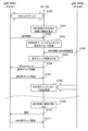
- FIG. 11 is a diagram showing a first operation example.
- cell #1 gNB 200 #1
- cell #2 gNB 200 #2
- PLMN #2 PLMN #2
- step S100 the UE 100 is in the RRC connected state in cell #1.
- step S101 the UE 100 is receiving MBS or is interested in receiving MBS.
- MBS e.g, a broadcast session
- receiving MBS may be a state in which an MBS session provided by ROM/FTA from cell #2 is being received.
- the UE 100 may acquire in advance upper layer information indicating the correspondence relationship between MBS sessions (MBS session identifiers) and frequencies (frequency identifiers) provided by the ROM/FTA.
- the higher layer information may further include information indicating the start time of the MBS session and/or information indicating the MBS service area in which the MBS session is provided.
- UE 100 may grasp the desired MBS frequency that provides the MBS session (desired MBS session) based on the higher layer information.
- Such upper layer information may be provided as a USD (User Service Description), or may be provided by NAS messages (eg, REGISTRATION ACCEPT message, CONFIGURATION UPDATE COMMAND message, or PDU SESSION ESTABLISHMENT ACCEPT message).
- step S102 the UE 100 sends the MBS information indicating the correspondence relationship between the MBS session and the frequency provided by the network 50 # 1 (PLMN # 1) and / or the MBS session provided by the ROM / FTA by the cell # 1 to the cell.
- MBS information may be information broadcast in the SIB or MCCH of cell #1.
- MBS information indicating the correspondence between MBS sessions and frequencies provided by network 50#1 may include multiple sets of MBS session identifiers and frequency identifiers. The UE 100 can grasp which MBS session is provided on which frequency based on such MBS information.
- the MBS information indicating the MBS sessions provided by the ROM/FTA by the cell #1 may include the MBS session identifier list of the MBS sessions provided by the ROM/FTA by the cell #1. Based on such MBS information, the UE 100 can grasp which MBS session the cell #1 provides in the ROM/FTA.
- the UE 100 recognizes, based on the MBS information received at step S102, that the desired MBS session to which the ROM/FTA is applied is not provided from the network 50#1 (PLMN#1).
- UE 100 is based on MBS information indicating the correspondence relationship between MBS sessions and frequencies provided by network 50 #1, and if the desired MBS session and/or desired MBS frequency are not indicated in the MBS information, the desired MBS It may be recognized that the session is not served from network 50#1 (PLMN#1). If the desired MBS frequency providing the desired MBS session to which the ROM/FTA is applied is not indicated in the MBS information, the desired MBS session and/or the desired MBS frequency of the UE 100 is another network, that is, the network 50 # 1 ( It may be recognized that it may be provided from PLMN #1).
- the desired MBS session is not indicated by the MBS information based on the MBS information indicating the MBS session provided by the ROM/FTA of the cell #1, the desired MBS session is determined by the network 50 #1 (PLMN # 1), the desired MBS session and/or desired MBS frequency may be provided by another network, namely network 50#1 (PLMN#1).
- the UE 100 receives the MBS information indicating the correspondence relationship between the MBS session provided by the network 50 #2 (PLMN #2) and the frequency and/or the MBS session provided by the cell #2 in the ROM/FTA. It may be received from #2 (gNB 200 #2). Such MBS information may be information broadcast in the SIB or MCCH of cell #2. UE 100 may confirm that the desired MBS session and/or the desired MBS frequency are provided from cell #2 based on the MBS information.
- the UE 100 receives the MBS reception setting in cell #2 from cell #2.
- MBS reception configuration includes MCCH configuration information broadcast in SIB of cell #2 (MBS SIB) and/or MTCH configuration information broadcast in MCCH of cell #2.
- MBS SIB MCCH configuration information broadcast in SIB of cell #2
- MTCH configuration information broadcast in MCCH of cell #2.
- UE 100 receives MCCH setting information from cell #2 by MBS SIB transmitted on BCCH, and then receives MTCH setting information by receiving MCCH from gNB 200 based on the MCCH setting information.
- the MCCH configuration information includes MCCH scheduling information, that is, information indicating MCCH reception timing (MCCH reception opportunity).
- the MTCH configuration information includes MTCH scheduling information, that is, information indicating MTCH reception timing (MTCH reception opportunity).
- Such MCCH reception timing (MCCH reception opportunity) and/or MTCH reception timing (MTCH reception opportunity) corresponds to MBS reception timing at which UE 100 receives MBS from cell #2.
- the MTCH reception timing that configures the MBS reception timing may be the MTCH reception timing associated with the desired MBS session, among the MTCH reception timings indicated by MCCH for each MBS session.
- step S105 the UE 100 determines the gap pattern setting of the MBS gap for interrupting data communication with the cell #1 based on the MBS reception timing ascertained in step S104, and requests gap information indicating the determined gap pattern setting.
- a gap pattern is a pattern of MBS gaps that is periodically repeated.
- the requested gap information includes information indicating the start timing of the gap pattern (system frame number and/or subframe number, etc.) and information indicating the gap pattern, for example, a bitmap for each subframe or MBS gap period (cycle length ) and
- the requested gap information may include information indicating the duration of each MBS gap. Note that the UE 100 determines the requested gap pattern in accordance with the timing (system frame number, etc.) of the cell #1.
- the UE 100 determines the time (margin) required to change the frequency of the receiver of the UE 100 and / or the measurement time for establishing synchronization with the cell # 2 to the requested gap pattern. may be added.
- step S106 the UE 100 transmits an RRC message containing the request gap information generated in step S105 to cell #1 (gNB 200 #1).
- the UE 100 may further include a desired MBS session identifier (eg, TMGI) and/or a desired MBS frequency identifier associated with the requested gap information in the RRC message.
- TMGI desired MBS session identifier
- cell #1 (gNB 200 #1) generates an MBS gap setting indicating an MBS gap setting (gap pattern) based on the requested gap information in the RRC message received from UE 100 in step S106. , transmits the MBS gap setting to the UE 100 .
- cell # 1 (gNB 200 # 1 ) transmits an RRC Reconfiguration message including MBS gap configuration to UE 100 .
- the type of information included in the gap configuration for MBS may be similar to the type of information included in the requested gap information.
- Cell #1 (gNB 200 #1) may further include the cell identifier and/or cell group identifier associated with the MBS gap configuration in the RRC reconfiguration message.
- Cell #1 (gNB 200 #1) may include multiple sets of MBS gap configuration and cell identifiers and/or cell group identifiers in the RRC reconfiguration message.
- step S108 the UE 100 suspends data communication with the cell #1 (gNB200 #1) in the MBS gap indicated by the MBS gap setting received from the cell #1 (gNB200 #1) in step S107, and the cell MBS reception of the desired MBS session from #2 (gNB200#2) is performed. Specifically, UE 100 changes (tunes) the reception frequency of the receiver from frequency # 1 to frequency # 2, and receives MBS from cell # 2 (gNB 200 # 2), that is, MTCH reception (and MCCH receive). Cell #1 (gNB 200 #1) does not allocate radio resources to the UE 100 during the set MBS reception gap.
- UE 100 uses multiple serving cells (or multiple cell groups) to communicate with network 50 # 1 (i.e., carrier aggregation or dual connectivity)
- UE 100 is the cell in the RRC reconfiguration message
- identify the serving cell (and / or cell group) to which the gap setting for MBS is applied using the receiver assigned to the identified serving cell (and / or cell group) MBS reception from cell #2 (gNB 200 #2) may be performed.
- the receiver assigned to a serving cell (and/or cell group) other than the specified serving cell (and/or cell group) remains on the same frequency/serving cell and continues receiving from the serving cell.
- the UE 100 may notify cell #1 (gNB 200 #1) (step S110).
- the UE 100 may send the notification in an RRC message, such as a UE Assistance Information message or an MBS Interest Indication message.
- the notification may be a request for clearing the gap.
- the notification may also be an MBS reception gap request that does not contain a request gap pattern.
- the cell #1 (gNB 200 #1) may remove (release) the MBS reception gap configuration from the UE 100 (step S111).
- UE 100 determines the request gap pattern.
- UE 100 transmits an RRC message including configuration information indicating MCCH configuration and/or MTCH configuration of cell #2 to cell #1 (gNB 200 #1) without determining the request gap pattern.
- the UE 100 may transfer the MBS reception configuration received from the cell #2 to the cell #1 (gNB 200 #1).
- Cell # 1 receives the RRC message from UE 100 , determines a gap pattern based on the MBS reception configuration in the RRC message, and configures the gap pattern in UE 100 .
- FIG. 12 is a diagram showing a second operation example. Here, differences from the first operation example described above will be described, and redundant description will be omitted.
- the UE 100 transmits to cell #1 (gNB 200 #1) an RRC message including at least part of the MBS reception information received from cell #2 in step S104.
- the UE 100 includes MCCH configuration information and/or MTCH configuration information for cell #2 in the RRC message.
- UE 100 may include only the MTCH configuration information (MTCH scheduling information) associated with the desired MBS session in the RRC message among the MTCH configuration information (MTCH scheduling information) for each MBS session.
- MTCH scheduling information MTCH scheduling information
- MTCH scheduling information the amount of shift (offset) in the RRC message.
- UE 100 may further include the desired MBS session identifier (eg, TMGI) and/or the desired MBS frequency identifier in the RRC message.
- cell #1 determines a gap pattern in the same manner as in step S105 above, based on the MBS reception setting in the RRC message received from UE 100 in step S106.
- Cell #1 (gNB 200 #1) then transmits to UE 100 an MBS gap setting indicating an MBS gap setting (gap pattern).
- cell # 1 (gNB 200 # 1 ) transmits an RRC Reconfiguration message including MBS gap configuration to UE 100 .
- Cell #1 (gNB 200 #1) may further include the cell identifier and/or cell group identifier associated with the MBS gap configuration in the RRC reconfiguration message, as in the first operation example described above.
- the UE 100 When the UE 100 is in the RRC idle state, the UE 100 monitors paging transmitted from the network 50#1, specifically, the AMF 300A#1 included in the CN 20#1 via the cell #1 (gNB 200#1). There is a need. When such paging reception timing (paging reception opportunity) and MBS reception timing (MBS reception opportunity) from cell #2 at least partially overlap, UE 100 appropriately receives MBS from cell #2. difficult to do.
- UE 100 transmits a NAS message regarding MBS reception timing for UE 100 to receive MBS from cell #2 to AMF 300A #1 via cell #1 (gNB 200 #1).
- UE 100 may transmit to AMF 300A#1 a NAS message including request information requesting a change in paging reception timing.
- the request information may include request gap information as in the first operation example described above.
- the request information may include MBS reception settings as in the second operation example described above.
- AMF 300A#1 Based on the received request information, AMF 300A#1 transmits to UE 100 via cell #1 (gNB 200#1) a paging reception setting that sets paging reception timing so as to avoid MBS reception timing in cell #2. . That is, AMF 300A#1 adjusts the paging reception timing of UE 100 so as to avoid MBS reception timing in cell #2. In this operation example, AMF 300A#1 corresponds to the paging management device.
- UE 100 in the RRC idle state monitors paging from cell #1 at the adjusted paging reception timing based on the paging reception setting from AMF 300A#1, and also monitors paging from cell #2 at timing different from the paging reception timing. MBS reception. This allows the UE 100 to receive MBS from the cell #2 while maintaining the RRC idle state in the cell #1.
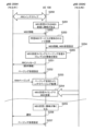
- FIG. 13 is a diagram showing a third operation example.
- differences from the first operation example and the second operation example described above will be mainly described, and redundant description will be omitted.
- step S200 the UE 100 is in the RRC idle state in cell #1.
- UE 100 in the RRC idle state in cell #1 monitors paging from cell #1 (gNB 200 #1). Specifically, UE 100 monitors paging transmitted from cell #1 (gNB 200 #1) at paging reception timing (paging occasion) determined according to parameters such as its own UE identifier.
- step S201 the UE 100 is receiving MBS or is interested in receiving MBS.
- MBS session eg, a broadcast session
- the UE 100 receives the MBS information indicating the correspondence relationship between the MBS session and the frequency provided by the network 50 # 1 (PLMN # 1) and / or the MBS session provided by the cell # 1 in the ROM / FTA. Receive from #1 (gNB 200 #1).
- MBS information may be information broadcast in the SIB or MCCH of cell #1.
- the UE 100 recognizes, based on the MBS information received at step S102, that the desired MBS session to which the ROM/FTA is applied is not provided from the network 50#1 (PLMN#1).
- step S204 the UE 100 sends the MBS information indicating the correspondence relationship between the MBS session provided by the network 50 #2 (PLMN #2) and the frequency and/or the MBS session provided by the cell #2 in the ROM/FTA to the cell. It may be received from #2 (gNB 200 #2). UE 100 may confirm that the desired MBS session and/or the desired MBS frequency are provided from cell #2 based on the MBS information.
- step S204 the UE 100 receives the MBS reception setting in cell #2 from cell #2, and grasps the MBS reception timing in cell #2.
- step S205 the UE 100 recognizes that the MBS reception timing in cell #2 overlaps (collides) with the paging reception timing in cell #1.
- UE 100 transmits a NAS message including request information requesting a change in paging reception timing to AMF 300A#1 via cell #1 (gNB 200#1).
- request information may be information requesting a change of the UE identity (eg 5G-S-TMSI), an alternative UE identity (i.e. the desired UE identity) or a UE identity offset value (i.e. , an offset value to be added to the UE identifier when calculating the paging reception timing, which may be a desired offset value).
- it may be information indicating a desired paging reception timing (PO: paging opportunity).
- the UE 100 may transmit the NAS message after transitioning from the RRC idle state to the RRC connected state.
- step S207 based on the received request information, AMF 300A#1 sets the paging reception setting to avoid MBS reception timing in cell #2 via cell #1 (gNB 200#1). It transmits to UE100.
- Such paging reception settings may include parameters that define the adjusted paging reception timing, eg, the UE identifier (5G-S-TMSI). Also, such paging reception settings may include an offset value to be added to the 5G-S-TMSI.
- the UE 100 may transition to the RRC idle state.
- UE 100 in the RRC idle state monitors paging from cell #1 at the adjusted paging reception timing based on the paging reception setting from AMF 300A #1 (step S208), and at a timing different from the paging reception timing. MBS reception from cell #2 is performed (step S209). Note that the order of steps S208 and S209 may be reversed.
- UE 100 When UE 100 loses interest in receiving MBS from cell #2 (gNB 200#2) (step S210), it may notify AMF 300A#1 (step S211).
- the UE 100 may make the notification after transitioning from the RRC idle state to the RRC connected state.
- the notification may be a request to unadjust the paging opportunity.
- the notification may be an adjustment request that does not include the request gap pattern.
- AMF 300A#1 may restore the paging reception setting in UE 100 (step S212).
- an example of transmitting a NAS message from UE 100 to AMF 300A#1 in step S206 has been described.
- an RRC message including request information may be transmitted from the UE 100 to the cell #1 (gNB 200 #1) in step S206.
- Cell #1 (gNB 200#1) may forward the received request information to AMF 300A#1 over the NG interface.
- FIG. 14 is a diagram showing a fourth operation example. Here, differences from the above-described third operation example will be described, and redundant description will be omitted.
- the UE 100 is in the RRC inactive state in cell #1.
- UE 100 in the RRC inactive state in cell #1 monitors paging from cell #1 (gNB 200 #1). Specifically, UE 100 monitors paging transmitted from cell #1 (gNB 200 #1) at paging reception timing (paging occasion) determined according to parameters such as its own UE identifier.
- step S251 the UE 100 transmits to cell #1 (gNB 200 #1) an RRC message including request information requesting a change in paging reception timing.
- the UE 100 may transmit the RRC message after transitioning from the RRC inactive state to the RRC connected state.
- the cell #1 transmits to the UE 100, based on the received request information, a paging reception setting for setting the paging reception timing so as to avoid the MBS reception timing in the cell #2.
- paging reception settings may include parameters that define the adjusted paging reception timing, eg, the UE identifier (5G-S-TMSI). Also, such paging reception settings may include an offset value to be added to the 5G-S-TMSI.
- the UE 100 may transition to the RRC inactive state. Note that steps S251 and S252 may be performed between AMF 300A#1 and UE 100, like steps S206 and S207 in the third operation example. In this case, AMF 300A#1 or UE 100 may notify gNB 200#1 of parameters that determine the adjusted paging reception timing using an NG-AP message or an RRC message.
- UE 100 in the RRC inactive state monitors paging from cell #1 at the adjusted paging reception timing based on the paging reception setting from cell #1 (gNB 200 #1) (step S253), and monitors the paging MBS reception from cell #2 is performed at a timing different from the reception timing (step S254). Note that the order of steps S253 and S254 may be reversed.
- the UE 100 When the UE 100 loses interest in receiving MBS from cell #2 (gNB 200 #2) (step S255), it may notify cell #1 (gNB 200 #1) (step S256).
- the UE 100 may make the notification after transitioning from the RRC inactive state to the RRC connected state.
- the notification may be a request to unadjust the paging opportunity.
- the notification may be an adjustment request that does not include the request gap pattern.
- Cell #1 (gNB 200 #1) may restore the paging reception setting in UE 100 based on the notification (step S257).
- the UE 100 receives the broadcast information (MBS information) indicating the MBS session being provided by the cell in the ROM/FTA from the cell in SIB or MCCH. That is, the cell (gNB 200) broadcasts MBS information indicating the MBS session being provided by the own cell in ROM/FTA. UE 100 identifies the MBS session being provided by the cell in ROM/FTA based on the broadcast information (MBS information).
- MBS information broadcast information
- MBS information indicating the MBS session being provided by the cell in the ROM/FTA from the cell in SIB or MCCH. That is, the cell (gNB 200) broadcasts MBS information indicating the MBS session being provided by the own cell in ROM/FTA.
- UE 100 identifies the MBS session being provided by the cell in ROM/FTA based on the broadcast information (MBS information).
- Such an operation may be used in a cell reselection procedure performed by UE 100 in RRC idle state or RRC inactive state. For example, when UE 100 in RRC idle state or RRC inactive state is receiving or interested in receiving a desired MBS session to which ROM/FTA is applied, preferentially reselect a cell that provides the desired MBS session. , camps on the cell.
- the UE 100 may receive MBS information broadcast from the cell and determine whether the cell provides the desired MBS session. When determining that the cell provides the desired MBS session, the UE 100 may determine the frequency to which the cell belongs as the highest priority for cell reselection.
- cell #1 is a cell belonging to PLMN #1 and cell #2 is a cell belonging to PLMN #2.
- cell #1 and cell #2 may belong to the same PLMN, not limited to such an inter-PLMN scenario.
- an inter-frequency scenario is assumed, an intra-frequency scenario, that is, a scenario in which cell #1 and cell #2 are operated on the same frequency, may be used.
- MBS reception from cell #2 is reception of an MBS session provided by ROM/FTA.
- the MBS session provided by cell #2 (gNB 200#2) is not necessarily ROM/FTA.
- the MBS session provided by cell #2 (gNB 200#2) may be a broadcast session or a multicast session.
- Each operation flow described above is not limited to being implemented independently, but can be implemented by combining two or more operation flows. For example, some steps of one operation flow may be added to another operation flow, or some steps of one operation flow may be replaced with some steps of another operation flow.
- the base station may be an NR base station (gNB) or a 6G base station.
- the base station may be a relay node such as an IAB (Integrated Access and Backhaul) node.
- IAB Integrated Access and Backhaul
- a base station may be a DU of an IAB node.
- the user equipment may be an MT (Mobile Termination) of an IAB node.
- a program that causes a computer to execute each process performed by the UE 100 or the gNB 200 may be provided.
- the program may be recorded on a computer readable medium.
- a computer readable medium allows the installation of the program on the computer.
- the computer-readable medium on which the program is recorded may be a non-transitory recording medium.
- the non-transitory recording medium is not particularly limited, but may be, for example, a recording medium such as CD-ROM or DVD-ROM.
- a circuit that executes each process performed by the UE 100 or gNB 200 may be integrated, and at least part of the UE 100 or gNB 200 may be configured as a semiconductor integrated circuit (chipset, SoC: System on a chip).
- the terms “based on” and “depending on,” unless expressly stated otherwise, “based only on.” does not mean The phrase “based on” means both “based only on” and “based at least in part on.” Similarly, the phrase “depending on” means both “only depending on” and “at least partially depending on.” Also, “obtain/acquire” may mean obtaining information among stored information, or it may mean obtaining information among information received from other nodes. or it may mean obtaining the information by generating the information.
- the terms “include,” “comprise,” and variations thereof are not meant to include only the recited items, and may include only the recited items or in addition to the recited items. Means that it may contain further items.
- references to elements using the "first,” “second,” etc. designations used in this disclosure do not generally limit the quantity or order of those elements. These designations may be used herein as a convenient method of distinguishing between two or more elements. Thus, references to first and second elements do not imply that only two elements may be employed therein, or that the first element must precede the second element in any way.
- references to first and second elements do not imply that only two elements may be employed therein, or that the first element must precede the second element in any way.
- Mobile communication system 10 RAN 20: CN 100: UE 110: Reception unit 120: Transmission unit 130: Control unit 200: gNB 210: Transmitting unit 220: Receiving unit 230: Control unit 240: Backhaul communication unit
Landscapes
- Engineering & Computer Science (AREA)
- Computer Networks & Wireless Communication (AREA)
- Signal Processing (AREA)
- Multimedia (AREA)
- Mobile Radio Communication Systems (AREA)
Priority Applications (3)
| Application Number | Priority Date | Filing Date | Title |
|---|---|---|---|
| JP2023556374A JP7769002B2 (ja) | 2021-10-26 | 2022-10-20 | 通信方法 |
| US18/646,442 US20240298381A1 (en) | 2021-10-26 | 2024-04-25 | Communication method |
| JP2025183735A JP2026021454A (ja) | 2021-10-26 | 2025-10-30 | ユーザ装置、プロセッサ、プログラム、ネットワークノード及び移動通信システム |
Applications Claiming Priority (2)
| Application Number | Priority Date | Filing Date | Title |
|---|---|---|---|
| JP2021-174776 | 2021-10-26 | ||
| JP2021174776 | 2021-10-26 |
Related Child Applications (1)
| Application Number | Title | Priority Date | Filing Date |
|---|---|---|---|
| US18/646,442 Continuation US20240298381A1 (en) | 2021-10-26 | 2024-04-25 | Communication method |
Publications (1)
| Publication Number | Publication Date |
|---|---|
| WO2023074529A1 true WO2023074529A1 (ja) | 2023-05-04 |
Family
ID=86159380
Family Applications (1)
| Application Number | Title | Priority Date | Filing Date |
|---|---|---|---|
| PCT/JP2022/039136 Ceased WO2023074529A1 (ja) | 2021-10-26 | 2022-10-20 | 通信方法 |
Country Status (3)
| Country | Link |
|---|---|
| US (1) | US20240298381A1 (https=) |
| JP (2) | JP7769002B2 (https=) |
| WO (1) | WO2023074529A1 (https=) |
Families Citing this family (1)
| Publication number | Priority date | Publication date | Assignee | Title |
|---|---|---|---|---|
| CN113676297B (zh) * | 2020-05-14 | 2022-11-18 | 展讯通信(上海)有限公司 | 多卡ue数据传输方法及装置、存储介质、用户设备、基站 |
Family Cites Families (1)
| Publication number | Priority date | Publication date | Assignee | Title |
|---|---|---|---|---|
| EP3503452A1 (en) | 2017-12-22 | 2019-06-26 | Koninklijke KPN N.V. | Coordinated transmission to a client device served by multiple communication networks |
-
2022
- 2022-10-20 JP JP2023556374A patent/JP7769002B2/ja active Active
- 2022-10-20 WO PCT/JP2022/039136 patent/WO2023074529A1/ja not_active Ceased
-
2024
- 2024-04-25 US US18/646,442 patent/US20240298381A1/en active Pending
-
2025
- 2025-10-30 JP JP2025183735A patent/JP2026021454A/ja active Pending
Non-Patent Citations (2)
| Title |
|---|
| ZTE CORPORATION: "MBMS enhancement for supporting of V2X service", 3GPP TSG-RAN WG2#95, R2-165265, 12 August 2016 (2016-08-12), XP051142745 * |
| ZTE, SANECHIPS: "Discussion on MBS Enhancement in Rel-18", 3GPP TSG RAN #93E, RP-212392, 6 September 2021 (2021-09-06), XP052050368 * |
Also Published As
| Publication number | Publication date |
|---|---|
| JP7769002B2 (ja) | 2025-11-12 |
| US20240298381A1 (en) | 2024-09-05 |
| JP2026021454A (ja) | 2026-02-10 |
| JPWO2023074529A1 (https=) | 2023-05-04 |
Similar Documents
| Publication | Publication Date | Title |
|---|---|---|
| JP7742460B2 (ja) | 通信制御方法、ネットワークノード、プロセッサ、プログラム及び移動通信システム | |
| WO2022239690A1 (ja) | 通信制御方法及びユーザ装置 | |
| JP7610027B2 (ja) | 通信方法、ユーザ装置、チップセット、プログラム、及び移動通信システム | |
| WO2022085717A1 (ja) | 通信制御方法 | |
| US20240298217A1 (en) | Communication method | |
| JP7829651B2 (ja) | 通信方法、ネットワークノード、ユーザ装置、チップセット、プログラム、及び移動通信システム | |
| US20240179798A1 (en) | Communication method | |
| WO2022239691A1 (ja) | 通信制御方法 | |
| JP2026021454A (ja) | ユーザ装置、プロセッサ、プログラム、ネットワークノード及び移動通信システム | |
| US20240373509A1 (en) | Communication method | |
| JP2025106507A (ja) | 通信制御方法、ユーザ装置、プロセッサ、ネットワーク装置、移動通信システム及びプログラム | |
| WO2022080230A1 (ja) | 通信制御方法 | |
| JP7774675B2 (ja) | 通信方法、ユーザ装置、プロセッサ、プログラム、及び移動通信システム | |
| JP7728348B2 (ja) | 通信方法、ユーザ装置 | |
| US20240373510A1 (en) | Communication method | |
| US20250220773A1 (en) | Communication method and user equipment | |
| WO2023074721A1 (ja) | 通信方法及びユーザ装置 | |
| JP2025157386A (ja) | 通信方法、ユーザ装置、チップセット、プログラム、及び移動通信システム | |
| WO2024034569A1 (ja) | 通信方法 | |
| WO2022085644A1 (ja) | 通信制御方法 |
Legal Events
| Date | Code | Title | Description |
|---|---|---|---|
| 121 | Ep: the epo has been informed by wipo that ep was designated in this application |
Ref document number: 22886857 Country of ref document: EP Kind code of ref document: A1 |
|
| ENP | Entry into the national phase |
Ref document number: 2023556374 Country of ref document: JP Kind code of ref document: A |
|
| NENP | Non-entry into the national phase |
Ref country code: DE |
|
| 122 | Ep: pct application non-entry in european phase |
Ref document number: 22886857 Country of ref document: EP Kind code of ref document: A1 |