WO2023074490A1 - 車載用アンテナ装置 - Google Patents
車載用アンテナ装置 Download PDFInfo
- Publication number
- WO2023074490A1 WO2023074490A1 PCT/JP2022/038896 JP2022038896W WO2023074490A1 WO 2023074490 A1 WO2023074490 A1 WO 2023074490A1 JP 2022038896 W JP2022038896 W JP 2022038896W WO 2023074490 A1 WO2023074490 A1 WO 2023074490A1
- Authority
- WO
- WIPO (PCT)
- Prior art keywords
- antenna
- vehicle
- monopole
- monopole antenna
- parasitic element
- Prior art date
- Legal status (The legal status is an assumption and is not a legal conclusion. Google has not performed a legal analysis and makes no representation as to the accuracy of the status listed.)
- Ceased
Links
Images


Classifications
-
- H—ELECTRICITY
- H01—ELECTRIC ELEMENTS
- H01Q—ANTENNAS, i.e. RADIO AERIALS
- H01Q1/00—Details of, or arrangements associated with, antennas
- H01Q1/27—Adaptation for use in or on movable bodies
- H01Q1/32—Adaptation for use in or on road or rail vehicles
- H01Q1/325—Adaptation for use in or on road or rail vehicles characterised by the location of the antenna on the vehicle
- H01Q1/3275—Adaptation for use in or on road or rail vehicles characterised by the location of the antenna on the vehicle mounted on a horizontal surface of the vehicle, e.g. on roof, hood, trunk
-
- B—PERFORMING OPERATIONS; TRANSPORTING
- B60—VEHICLES IN GENERAL
- B60R—VEHICLES, VEHICLE FITTINGS, OR VEHICLE PARTS, NOT OTHERWISE PROVIDED FOR
- B60R11/00—Arrangements for holding or mounting articles, not otherwise provided for
- B60R11/02—Arrangements for holding or mounting articles, not otherwise provided for for radio sets, television sets, telephones, or the like; Arrangement of controls thereof
-
- H—ELECTRICITY
- H01—ELECTRIC ELEMENTS
- H01Q—ANTENNAS, i.e. RADIO AERIALS
- H01Q1/00—Details of, or arrangements associated with, antennas
- H01Q1/42—Housings not intimately mechanically associated with radiating elements, e.g. radome
-
- H—ELECTRICITY
- H01—ELECTRIC ELEMENTS
- H01Q—ANTENNAS, i.e. RADIO AERIALS
- H01Q19/00—Combinations of primary active antenna elements and units with secondary devices, e.g. with quasi-optical devices, for giving the antenna a desired directional characteristic
- H01Q19/28—Combinations of primary active antenna elements and units with secondary devices, e.g. with quasi-optical devices, for giving the antenna a desired directional characteristic using a secondary device in the form of two or more substantially straight conductive elements
- H01Q19/32—Combinations of primary active antenna elements and units with secondary devices, e.g. with quasi-optical devices, for giving the antenna a desired directional characteristic using a secondary device in the form of two or more substantially straight conductive elements the primary active element being end-fed and elongated
-
- H—ELECTRICITY
- H01—ELECTRIC ELEMENTS
- H01Q—ANTENNAS, i.e. RADIO AERIALS
- H01Q21/00—Antenna arrays or systems
- H01Q21/28—Combinations of substantially independent non-interacting antenna units or systems
-
- H—ELECTRICITY
- H01—ELECTRIC ELEMENTS
- H01Q—ANTENNAS, i.e. RADIO AERIALS
- H01Q9/00—Electrically-short antennas having dimensions not more than twice the operating wavelength and consisting of conductive active radiating elements
- H01Q9/04—Resonant antennas
- H01Q9/30—Resonant antennas with feed to end of elongated active element, e.g. unipole
- H01Q9/32—Vertical arrangement of element
- H01Q9/36—Vertical arrangement of element with top loading
Definitions
- the present invention relates to an in-vehicle antenna device.
- an in-vehicle antenna device described in Patent Literature 1 includes a plurality of dipole antennas. A plurality of dipole antennas are arranged in the longitudinal direction of the vehicle.
- the antenna accommodated in the accommodation space is a V2X antenna
- a plurality of dipole antennas may be used as described in Patent Document 1, for example.
- the construction of dipoles can be relatively complex.
- V2X antennas may use frequencies in the 5.9 MHz band. In this case, the wavelength of the frequency used by the V2X antenna will be a relatively short wavelength. Therefore, it is required to make the configuration of the V2X antenna relatively simple.
- An example of the object of the present invention is to enhance the directivity of the antenna housed in the housing space of the antenna case in a desired direction with a simple configuration.
- One aspect of the present invention is an antenna case having a longitudinal direction; a plurality of monopole antennas housed in the housing space of the antenna case; with The plurality of monopole antennas are an in-vehicle antenna device arranged in a direction intersecting the longitudinal direction.
- One aspect of the present invention is an antenna case having a longitudinal direction; a monopole antenna housed in the housing space of the antenna case; a parasitic element accommodated in the accommodation space; with The monopole antenna and the parasitic element are arranged in a direction intersecting the longitudinal direction of the on-vehicle antenna device.
- One aspect of the present invention is an antenna case having a longitudinal direction; a monopole antenna housed in the housing space of the antenna case; a parasitic element accommodated in the accommodation space; with The monopole antenna and the parasitic element are arranged along the longitudinal direction of the on-vehicle antenna device.
- One aspect of the present invention is an antenna case having a longitudinal direction; An antenna element housed in the housing space of the antenna case; a pair of capacitive loading elements housed in the housing space and arranged in a direction crossing the longitudinal direction; with At least a portion of the antenna element is a vehicle-mounted antenna device positioned between the pair of capacitive loading elements.
- the directivity of the antenna accommodated in the accommodation space of the antenna case can be enhanced in a desired direction with a simple configuration.
- FIG. 1 is a perspective view of a vehicle-mounted antenna device according to Embodiment 1.
- FIG. 3 is a perspective view of an antenna section according to Embodiment 1.
- FIG. 2 is a perspective view of an in-vehicle antenna device according to Comparative Example 1.
- FIG. 3 is a perspective view of an antenna section according to Comparative Example 1.
- FIG. 4 is a graph showing the horizontal directivity of the array antenna in the vehicle-mounted antenna device according to Embodiment 1.
- FIG. 4 is a graph showing the horizontal directivity of the array antenna in the antenna section according to Embodiment 1.
- FIG. 7 is a graph showing the horizontal directivity of the monopole antenna in the in-vehicle antenna device according to Comparative Example 1.
- FIG. 9 is a graph showing the horizontal directivity of the monopole antenna in the antenna section according to Comparative Example 1.
- FIG. 10 is a perspective view of an in-vehicle antenna device according to Embodiment 2; 8 is a perspective view of an antenna section according to Embodiment 2.
- FIG. 9 is a graph showing the horizontal directivity of the monopole antenna in the vehicle-mounted antenna device according to Embodiment 2.
- FIG. 9 is a graph showing the horizontal directivity of a monopole antenna in the antenna section according to Embodiment 2.
- FIG. FIG. 11 is a perspective view of an in-vehicle antenna device according to Embodiment 3; FIG.
- FIG. 11 is a perspective view of an antenna section according to Embodiment 3; 10 is a graph showing the horizontal directivity of the monopole antenna in the vehicle-mounted antenna device according to Embodiment 3.
- FIG. 10 is a graph showing the horizontal directivity of the monopole antenna in the antenna section according to Embodiment 3.
- FIG. 12 is a perspective view of an in-vehicle antenna device according to Embodiment 4;
- FIG. 12 is a perspective view of an antenna section according to Embodiment 4;
- 10 is a graph showing the horizontal directivity of the monopole antenna in the vehicle-mounted antenna device according to Embodiment 4.
- FIG. 10 is a graph showing the horizontal directivity of the monopole antenna in the antenna section according to Embodiment 4.
- FIG. 11 is a perspective view of a vehicle-mounted antenna device according to Embodiment 5;
- FIG. 11 is an enlarged top view of a collinear array antenna and a pair of first capacitive loading elements in a vehicle-mounted antenna device according to Embodiment 5;
- FIG. 11 is an enlarged top view of a collinear array antenna and a pair of first capacitive loading elements in a vehicle-mounted antenna device according to a modification;
- 14 is a graph showing the horizontal plane directivity of the collinear array antenna in each of the vehicle-mounted antenna device according to Embodiment 5, the vehicle-mounted antenna device according to the modified example, and the vehicle-mounted antenna device according to Comparative Example 2.
- FIG. FIG. 11 is an enlarged top view of a collinear array antenna and a pair of first capacitive loading elements in a vehicle-mounted antenna device according to Comparative Example 2;
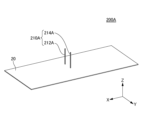
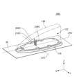
- FIG. 1 is a perspective view of a vehicle-mounted antenna device 10A according to Embodiment 1.
- FIG. 1 is a perspective view of a vehicle-mounted antenna device 10A according to Embodiment 1.
- the arrows indicating the first direction X, the second direction Y, or the third direction Z indicate that the direction from the base end of the arrow to the tip is the positive direction of the direction indicated by the arrow, and the tip of the arrow to the proximal end is the negative direction of the direction indicated by the arrow.
- the first direction X is a direction parallel to the front-rear direction of the vehicle-mounted antenna device 10A.
- the positive direction of the first direction X is the direction from the rear to the front of the vehicle-mounted antenna device 10A.
- the negative direction of the first direction X is the direction from the front to the rear of the in-vehicle antenna device 10A.
- the second direction Y is orthogonal to the first direction X. As shown in FIG.
- the second direction Y is parallel to the lateral direction of the in-vehicle antenna device 10A.
- the positive direction of the second direction Y is a direction from right to left of the vehicle-mounted antenna device 10A as viewed from behind the vehicle-mounted antenna device 10A.
- the negative direction of the second direction Y is a direction from left to right of the vehicle-mounted antenna device 10A as viewed from behind the vehicle-mounted antenna device 10A.
- the third direction Z is orthogonal to both the first direction X and the second direction Y. As shown in FIG.
- the third direction Z is a direction parallel to the vertical direction of the in-vehicle antenna device 10A.
- the positive direction of the third direction Z is the direction from the bottom to the top of the in-vehicle antenna device 10A.
- the negative direction of the third direction Z is a direction from above to below the vehicle-mounted antenna device 10A.
- the in-vehicle antenna device 10A includes an antenna base 110, an antenna case 120 and an array antenna 210A.
- the array antenna 210A has a first monopole antenna 212A and a second monopole antenna 214A.
- the antenna base 110 and the array antenna 210A are shown through the antenna case 120 for the sake of explanation.
- the antenna base 110 is provided on the upper surface side of the base plate 20 .
- the antenna base 110 has, for example, at least one of a metal base and a resin base.
- the ground plate 20 is, for example, the roof of an automobile.
- the ground plane 20 is assumed to extend infinitely in a direction perpendicular to the third direction Z unless otherwise specified.
- the antenna case 120 has radio wave transparency.
- the antenna case 120 is made of resin, for example.
- the antenna case 120 forms a housing space 122 together with the antenna base 110 .
- the housing space 122 houses a first monopole antenna 212A and a second monopole antenna 214A. That is, the antenna case 120 serves as a radome for the first monopole antenna 212A and the second monopole antenna 214A.
- the antenna case 120 covers the accommodation space 122 from above.
- the height of the antenna case 120 in the third direction Z increases from the front end of the antenna case 120 toward the rear end of the antenna case 120 . Therefore, the height of the accommodation space 122 in the third direction Z also increases from the front end of the antenna case 120 toward the rear end of the antenna case 120 .
- the length of the antenna case 120 in the first direction X is longer than the length of the antenna case 120 in the second direction Y. That is, the antenna case 120 has a longitudinal direction in the first direction X and a lateral direction in the second direction Y. As shown in FIG. Accordingly, the length of the accommodation space 122 in the first direction X is also longer than the length of the accommodation space 122 in the second direction Y. As shown in FIG.
- the directivity of the array antenna 210A is affected by the antenna case 120. Specifically, the directivity of array antenna 210A in the direction in which the distance from array antenna 210A to the inner wall of antenna case 120 is relatively short is relatively less affected by antenna case 120 . On the other hand, the directivity of array antenna 210A in the direction in which the distance from array antenna 210A to the inner wall of antenna case 120 is relatively long is relatively easily affected by antenna case 120 . Therefore, for example, when a single monopole antenna is arranged near the center of the accommodation space 122 in the first direction X and the second direction Y when viewed from the third direction Z, the directivity of the monopole antenna in the second direction Y The directivity of the monopole antenna in the first direction X becomes relatively weak. In contrast, according to the first embodiment, even if the array antenna 210A is accommodated in the accommodation space 122, the directivity of the array antenna 210A in the first direction X can be enhanced.
- the first monopole antenna 212A and the second monopole antenna 214A according to Embodiment 1 are half-wave monopole antennas.
- the configurations of the first monopole antenna 212A and the second monopole antenna 214A can be simplified compared to configurations of other antennas such as dipole antennas. Therefore, according to the first embodiment, the array antenna 210A can have a relatively simple configuration.
- the first monopole antenna 212A and the second monopole antenna 214A are provided on the upper surface side of the base plate 20 .
- the first monopole antenna 212A and the second monopole antenna 214A are arranged substantially perpendicular to the ground plane 20 .
- the lower end of the first monopole antenna 212A, which faces the ground plane 20, serves as a feeding portion of the first monopole antenna 212A.
- a lower end of the second monopole antenna 214A facing the ground plane 20 serves as a feeding portion of the second monopole antenna 214A.
- the wavelength of the frequency used in the array antenna 210A is ⁇ A .
- the length of the first monopole antenna 212A in the third direction Z and the length of the second monopole antenna 214A in the third direction Z are substantially equal to 1/2 times the wavelength ⁇ A .
- the first monopole antenna 212A and the second monopole antenna 214A are arranged in a direction crossing the first direction X. Specifically, the first monopole antenna 212A is located on the right side of the imaginary centerline LXA, and the second monopole antenna 214A is located on the left side of the imaginary centerline LXA.
- the imaginary centerline LXA passes through the center of the accommodation space 122 in the second direction Y in the first direction X.
- the first monopole antenna 212A and the second monopole antenna 214A are arranged on the imaginary intersection line LYA.
- the imaginary intersection line LYA intersects the imaginary center line LXA and passes through the first monopole antenna 212A and the second monopole antenna 214A in the second direction Y.
- the first monopole antenna 212A and the second monopole antenna 214A are located substantially symmetrically with respect to the virtual center line LXA.
- the imaginary center line LXA is the perpendicular bisector of the imaginary line segment connecting the first monopole antenna 212A and the second monopole antenna 214A. Therefore, the difference between the influence of the inner wall of the antenna case 120 on the right side of the housing space 122 on the directivity of the array antenna 210A and the influence of the inner wall of the antenna case 120 on the left side of the housing space 122 on the directivity of the array antenna 210A can be made smaller.
- the distance in the second direction Y between the first monopole antenna 212A and the second monopole antenna 214A is approximately equal to 1/2 times the wavelength ⁇ A , for example.
- the distance between the first monopole antenna 212A and the second monopole antenna 214A in the second direction Y may be between 3/8 and 5/8 times the wavelength ⁇ A .
- the distance in the second direction Y between the first monopole antenna 212A and the second monopole antenna 214A may be substantially equal to 1/4 times the wavelength ⁇ A .
- the distance between the first monopole antenna 212A and the second monopole antenna 214A in the second direction Y may be 1/8 to 3/8 times the wavelength ⁇ A .
- the first monopole antenna 212A and the second monopole antenna 214A are arranged along the second direction Y with a predetermined distance therebetween. Also, the first monopole antenna 212A and the second monopole antenna 214A are fed with substantially the same amplitude and substantially the same phase and are excited substantially simultaneously. As a result, when viewed from the positive direction of the third direction Z, radio waves radiated from the first monopole antenna 212A toward the virtual center line LXA and radio waves radiated from the second monopole antenna 214A toward the virtual center line LXA.
- the radio wave radiated in the second direction Y from the first monopole antenna 212A and the radio wave radiated in the second direction Y from the second monopole antenna 214A have substantially opposite phases, and the first monopole antenna 212A
- the radio waves radiated in the second direction Y from the pole antenna 212A and the radio waves radiated in the second direction Y from the second monopole antenna 214A cancel each other. Therefore, the directivity in the second direction Y of the array antenna 210A is weakened.
- the first monopole antenna 212A and the second monopole antenna 214A are arranged along the direction substantially perpendicular to the first direction X. From the above description, in Embodiment 1, compared to the case where the first monopole antenna 212A and the second monopole antenna 214A are arranged in a direction different from the direction substantially perpendicular to the first direction X, The directivity of the array antenna 210A in the first direction X can be further enhanced.
- the distance in the second direction Y between the first monopole antenna 212A and the second monopole antenna 214A is substantially equal to 1/2 times the wavelength ⁇ A
- the distance in the second direction Y between the first monopole antenna 212A and the second monopole antenna 214A is not limited to the example described above.
- the distance in the second direction Y between the first monopole antenna 212A and the second monopole antenna 214A is appropriately changed according to, for example, the distance from the inner wall of the antenna case 120 to the area where the array antenna 210A is arranged. can do.
- the position of the array antenna 210A in the first direction X is located at the center of the accommodation space 122 in the first direction X or its periphery. Therefore, the directivity of array antenna 210A is affected by the inner wall of antenna case 120 on the front side of accommodation space 122, and the directivity of array antenna 210A is affected by the inner wall of antenna case 120 on the rear side of accommodation space 122. can reduce the difference.
- the array antenna 210A when viewed from the third direction Z, can be positioned at the center of the housing space 122 in the first direction X or at a distance of 45% or less of the total length of the antenna case 120 in the first direction X from the center. can.
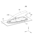
- FIG. 2 is a perspective view of the antenna section 200A according to Embodiment 1.
- FIG. An antenna unit 200A according to Embodiment 1 is the same as the vehicle-mounted antenna device 10A according to Embodiment 1, except for the following points.
- the antenna section 200A according to Embodiment 1 does not include the antenna base 110 and the antenna case 120.
- 200 A of antenna parts which concern on Embodiment 1 are equipped with the array antenna 210A like 10 A of vehicle-mounted antenna apparatuses which concern on Embodiment 1. As shown in FIG.
- FIG. 2 illustrates the configuration of the array antenna 210A that is not housed in the housing space 122. As shown in FIG. FIG. 2 compares the directivity of the array antenna 210A housed in the housing space 122 as shown in FIG. 1 and the directivity of the array antenna 210A not housed in the housing space 122 as shown in FIG. It is a diagram for
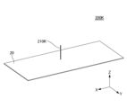
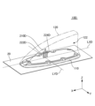
- FIG. 3 is a perspective view of a vehicle-mounted antenna device 10K according to Comparative Example 1.
- FIG. A vehicle-mounted antenna device 10K according to Comparative Example 1 is the same as the vehicle-mounted antenna device 10A according to Embodiment 1, except for the following points.
- a vehicle-mounted antenna device 10K according to Comparative Example 1 includes a single monopole antenna 210K.
- 3 shows a vehicle antenna device 10A according to Embodiment 1 of FIG. 1, a vehicle antenna device 10B according to Embodiment 2 of FIG. 9 described later, and a vehicle antenna device according to Embodiment 3 of FIG. 13 described later. 10C, and a vehicle-mounted antenna device 10D according to Embodiment 4 of FIG. 17 described later, and a vehicle-mounted antenna device 10K according to Comparative Example 1 of FIG. 3.
- Single monopole antenna 210K is a half-wave monopole antenna. Specifically, a single monopole antenna 210K is provided on the upper surface side of the base plate 20 . A single monopole antenna 210K is arranged substantially perpendicular to the ground plane 20 . The lower end of the single monopole antenna 210K, which faces the ground plane 20, serves as the feeding portion of the single monopole antenna 210K. Viewed from the third direction Z, the single monopole antenna 210K is positioned on the imaginary centerline LXK. The imaginary center line LXK passes through substantially the center of the accommodation space 122 in the second direction Y in parallel to the first direction X. As shown in FIG. The wavelength of the frequency used in the single monopole antenna 210K is ⁇ K . The length of the single monopole antenna 210K in the third direction Z is approximately equal to 1/2 times the wavelength ⁇ K .
- FIG. 4 is a perspective view of an antenna section 200K according to Comparative Example 1.
- FIG. An antenna section 200K according to Comparative Example 1 is the same as the in-vehicle antenna device 10K according to Comparative Example 1, except for the following points.
- the antenna section 200K according to Comparative Example 1 does not include the antenna base 110 and the antenna case 120 .
- An antenna section 200K according to Comparative Example 1 includes a single monopole antenna 210K in the same manner as the in-vehicle antenna device 10K according to Comparative Example 1.
- FIG. 1 is a single monopole antenna 210K in the same manner as the in-vehicle antenna device 10K according to Comparative Example 1.
- FIG. 4 illustrates the configuration of a single monopole antenna 210K that is not housed in the housing space 122.
- FIG. 4 shows the directivity of the single monopole antenna 210K housed in the housing space 122 as shown in FIG. 3 and the directivity of the single monopole antenna 210K not housed in the housing space 122 as shown in FIG.
- FIG. 10 is a diagram for comparing the directivity of .
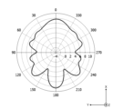
- FIG. 5 is a graph showing the horizontal directivity of the array antenna 210A in the vehicle-mounted antenna device 10A according to the first embodiment.
- FIG. 6 is a graph showing the in-horizontal directivity of the array antenna 210A in the antenna section 200A according to the first embodiment.
- FIG. 7 is a graph showing the in-horizontal directivity of a single monopole antenna 210K in the vehicle-mounted antenna device 10K according to Comparative Example 1.
- FIG. 8 is a graph showing the horizontal directivity of a single monopole antenna 210K in the antenna section 200K according to Comparative Example 1.
- FIG. 8 is a graph showing the horizontal directivity of a single monopole antenna 210K in the antenna section 200K according to Comparative Example 1.
- the "horizontal plane” means a plane perpendicular to the third direction Z.
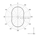
- the graphs of FIGS. 5 and 6 show the horizontal directivity of 5900 MHz, which is the frequency used in the array antenna 210A.
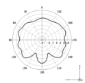
- the graphs of FIGS. 7 and 8 show the directivity in the horizontal plane at 5900 MHz, the frequency used in the single monopole antenna 210K.
- the numbers attached to the outer periphery of the graphs indicate the direction (unit: °) in the horizontal plane. 0°, 180°, 90° and 270° are forward, backward, left and right respectively.
- the dashed circles shown concentrically with respect to the center of the graphs indicate the sensitivity of the antenna (unit: dBi).
- the white circle with a black dot indicating the third direction Z is the positive direction of the third direction Z from the back to the front of the paper, and the third direction Z is the direction from the front to the back of the paper. is in the negative direction.
- the conditions of the in-vehicle antenna device 10A according to Embodiment 1 shown in FIG. 5 and the conditions of the antenna section 200A according to Embodiment 1 shown in FIG. 6 are as follows. That is, the total length of the antenna case 120 in the first direction X was set to 180 mm. The length in the third direction Z of the first monopole antenna 212A and the second monopole antenna 214A was 28.5 mm. The first monopole antenna 212A and the second monopole antenna 214A are arranged in the second Y direction. The first monopole antenna 212A and the second monopole antenna 214A are positioned symmetrically with respect to the virtual centerline LXA.
- the distance in the second direction Y between the first monopole antenna 212A and the second monopole antenna 214A was 16 mm.
- the distance in the first direction X from the front end of the antenna case 120 to the array antenna 210A was set to 70 mm.
- the conditions of the in-vehicle antenna device 10K according to Comparative Example 1 shown in FIG. 7 and the conditions of the antenna unit 200K according to Comparative Example 1 shown in FIG. 6 were the same. That is, the length of the single monopole antenna 210K in the third direction Z was 28.5 mm. Viewed from the third direction Z, the single monopole antenna 210K was positioned on the imaginary centerline LXK. The distance in the first direction X from the front end of the antenna case 120 to the single monopole antenna 210K was 70 mm.
- the directivity of the single monopole antenna 210K is omnidirectional. It is about 7dBi throughout. Therefore, when the single monopole antenna 210K is not accommodated in the accommodation space 122, the directivity of the single monopole antenna 210K is omnidirectional (omnidirectional) in the horizontal plane.
- the directivity of the single monopole antenna 210K is 0. 7dBi to 8dBi around ⁇ 30°, around 4dBi to 9dBi around 180° ⁇ 30°, around 8dBi to 10dBi around 90° ⁇ 30° and around 270° ⁇ 30°. It's becoming Therefore, in a state where the single monopole antenna 210K is housed in the housing space 122, the directivity of the single monopole antenna 210K in the positive and negative directions of the first direction X is the positive direction of the second direction Y. It is weaker than the directivity of a single monopole antenna 210K in both positive and negative directions.
- the directivity of the single monopole antenna 210K is affected by the antenna case 120.
- the distance from the single monopole antenna 210K to the inner wall of the antenna case 120 on both sides of the accommodation space 122 in the second direction Y is the distance from the single monopole antenna 210K to the accommodation space 122 in the first direction X and the distance from the single monopole antenna 210K to the inner wall of the antenna case 120 on the negative direction side of the first direction X of the accommodation space 122. It's getting shorter.
- the distance from the single monopole antenna 210K to the inner wall of the antenna case 120 is relatively short. It can be said that the directivity of 210K tends to be stronger than the directivity of the single monopole antenna 210K in the direction where the distance from the single monopole antenna 210K to the inner wall of the antenna case 120 is relatively long.
- the directivity of the array antenna 210A is around 0° ⁇ 30° and around 180° ⁇ 30°. It is about 8dBi to 9dBi, and about 3dBi to 5dBi near 90° ⁇ 30° and 270° ⁇ 30°. Therefore, in a state where the array antenna 210A is not accommodated in the accommodation space 122, the directivity of the array antenna 210A in the positive and negative directions of the first direction X is changed to that of the positive and negative directions of the second direction Y. directivity can be strengthened. That is, the directivity of the array antenna 210A in the longitudinal direction of the antenna case 120 can be enhanced when the array antenna 210A is not accommodated in the accommodation space 122.
- the directivity of the array antenna 210A is about 7dBi to 10dBi near 0° ⁇ 30°. 4dBi to 11dBi around 180° ⁇ 30°, and around 4dBi to 7dBi around 90° ⁇ 30° and 270° ⁇ 30°. Therefore, in a state where the array antenna 210A is housed in the housing space 122, the directivity of the array antenna 210A in the positive and negative directions of the first direction X is changed to the positive and negative directions of the second direction Y by the array antenna 210A. directivity can be strengthened. That is, in a state in which array antenna 210A is housed in housing space 122, the directivity of array antenna 210A in the longitudinal direction of antenna case 120 can be enhanced.
- the directivity in the positive direction and the negative direction in the second direction Y of the array antenna 210A according to Embodiment 1, which is not accommodated in the accommodation space 122 is It is weaker than the directivity in the positive and negative directions in the second direction Y of the single monopole antenna 210K according to Comparative Example 1, which is not housed in the space 122 .
- the directivity in the positive direction and the negative direction in the first direction X of the array antenna 210A according to the first embodiment when not accommodated in the accommodation space 122 is similar to that of the comparative example 1 when the array antenna 210A is not accommodated in the accommodation space 122. It is stronger than the directivity of the single monopole antenna 210K in the first direction X in the positive and negative directions.
- the directivity in the positive direction and the negative direction in the second direction Y of the array antenna 210A according to Embodiment 1 in the state accommodated in the accommodation space 122 is It is weaker than the directivity in the positive and negative directions in the second direction Y of the single monopole antenna 210K according to Comparative Example 1 in the state accommodated in the space 122 .
- the directivity in the positive direction and the negative direction in the first direction X of the array antenna 210A according to the first embodiment in the state accommodated in the accommodation space 122 is the same as that in the comparative example 1 in the state accommodated in the accommodation space 122. It is stronger than the directivity of the single monopole antenna 210K in the first direction X in the positive and negative directions.
- the configuration of the array antenna 210A is not limited to the configuration described using the first embodiment.
- At least one of the first monopole antenna 212A and the second monopole antenna 214A may be shifted forward or backward with respect to the imaginary intersection line LYA.
- the distance in the second direction Y between the first monopole antenna 212A and the imaginary centerline LXA and the distance in the second direction Y between the second monopole antenna 214A and the imaginary centerline LXA are They may be different from each other.
- the directivity of the array antenna 210A in at least one of the positive direction and the negative direction of the first direction X is achieved by appropriately adjusting predetermined conditions such as the arrangement and dimensions of the first monopole antenna 212A and the second monopole antenna 214A. can be made stronger than the directivity of the array antenna 210A in at least one of the positive direction and the negative direction of the second Y direction.
- the array antenna 210A may include three or more monopole antennas.
- four monopole antennas are arranged at four vertices of a quadrangle having two sides parallel to the first direction X and two sides parallel to the second direction Y. may have been
- the two sides parallel to the second direction Y may be longer than the two sides parallel to the first direction X, for example.
- first monopole antenna 212A and the second monopole antenna 214A may be quarter-wave monopole antennas. Further, the first monopole antenna 212A and the second monopole antenna 214A are not limited to linear, and may be plate-shaped.
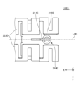
- FIG. 9 is a perspective view of a vehicle-mounted antenna device 10B according to Embodiment 2.
- FIG. The vehicle-mounted antenna device 10B according to Embodiment 2 is the same as the vehicle-mounted antenna device 10A according to Embodiment 1, except for the following points.
- a vehicle-mounted antenna device 10B according to Embodiment 2 includes a monopole antenna 210B, a first parasitic element 222B and a second parasitic element 224B.
- the monopole antenna 210B, the first parasitic element 222B and the second parasitic element 224B are housed in the housing space 122. As shown in FIG.
- a monopole antenna 210B according to the second embodiment is a half-wave monopole antenna. Specifically, the monopole antenna 210B is provided on the upper surface side of the base plate 20 . Monopole antenna 210B is arranged substantially perpendicular to ground plane 20 . A lower end of the monopole antenna 210B facing the ground plane 20 serves as a feeding portion of the monopole antenna 210B. The wavelength of the frequency used in the monopole antenna 210B is ⁇ B . The length of the monopole antenna 210B in the third direction Z is approximately equal to 1/2 times the wavelength ⁇ B .
- the monopole antenna 210B When viewed from the third direction Z, the monopole antenna 210B is positioned on the imaginary centerline LXB.
- the imaginary center line LXB passes through substantially the center of the housing space 122 in the second direction Y in parallel with the first direction X.
- the directivity of the monopole antenna 210B is affected by the inner wall of the antenna case 120 on the right side of the accommodation space 122
- the directivity of the monopole antenna 210B is affected by the inner wall of the antenna case 120 on the left side of the accommodation space 122, can reduce the difference between
- the first parasitic element 222B and the second parasitic element 224B are not grounded with respect to the ground plane 20. Specifically, the lower end of the first parasitic element 222B and the lower end of the second parasitic element 224B are not connected to the ground plane 20 . However, one of the first parasitic element 222B and the second parasitic element 224B may be grounded to the ground plane 20 . That is, at least one of the first parasitic element 222B and the second parasitic element 224B may be non-grounded with respect to the ground plane 20 .
- the length in the third direction Z of the first parasitic element 222B and the length in the third direction Z of the second parasitic element 224B are longer than the length in the third direction Z of the monopole antenna 210B.
- the length of the first parasitic element 222B in the third direction Z and the length of the second parasitic element 224B in the third direction Z are substantially equal to the wavelength ⁇ B .
- the first parasitic element 222B and the second parasitic element 224B are located on both sides in the second direction Y with respect to the virtual center line LXB. Therefore, monopole antenna 210B and first parasitic element 222B are arranged in a direction intersecting the longitudinal direction of antenna case 120 . Monopole antenna 210B and second parasitic element 224B are arranged in a direction crossing the longitudinal direction of antenna case 120 . Specifically, the first parasitic element 222B is located on the right side of the imaginary center line LXB. Thereby, the first parasitic element 222B is located between the right inner wall of the antenna case 120 and the monopole antenna 210B. The second parasitic element 224B is located on the left side with respect to the imaginary center line LXB.
- the second parasitic element 224B is located between the left inner wall of the antenna case 120 and the monopole antenna 210B.
- the first parasitic element 222B and the second parasitic element 224B can operate as reflecting elements that reflect radio waves radiated from the monopole antenna 210B. Therefore, it is possible to enhance the directivity of the monopole antenna 210B in a desired direction.
- the first parasitic element 222B and the second parasitic element 224B change the directivity of the monopole antenna 210B in at least one of the positive and negative directions of the second direction Y to the positive direction of the first direction X and the directivity of the monopole antenna 210B in at least one of the negative direction.
- the monopole antenna 210B, the first parasitic element 222B and the second parasitic element 224B are arranged in a direction substantially perpendicular to the first direction X. Specifically, when viewed from the third direction Z, the monopole antenna 210B, the first parasitic element 222B, and the second parasitic element 224B are positioned on the virtual intersection line LYB.
- the imaginary intersection line LYB intersects the imaginary centerline LXB and passes through the monopole antenna 210B in the second direction Y.
- the second direction The directivity of the monopole antenna 210B in at least one of the positive and negative directions of Y can be further weakened, and the directivity of the monopole antenna 210B in at least one of the positive and negative directions of the first direction X can be further strengthened. can be done.
- the distance in the second direction Y between the first parasitic element 222B and the second parasitic element 224B is the length of the first parasitic element 222B in the third direction Z and the length of the second parasitic element 224B in the third direction Z is shorter than the length of Also, the distance in the second direction Y between the first parasitic element 222B and the second parasitic element 224B is substantially equal to 1/2 times the wavelength ⁇ B .
- the first parasitic element 222B and the second parasitic element 224B are located at substantially equal distances from the monopole antenna 210B. Also, the length of the first parasitic element 222B in the third direction Z and the length of the second parasitic element 224B in the third direction Z are substantially equal to each other. However, the arrangement and dimensions of the first parasitic element 222B and the second parasitic element 224B are not limited to the arrangement and dimensions according to the second embodiment. For example, the distance between monopole antenna 210B and first parasitic element 222B and the distance between monopole antenna 210B and second parasitic element 224B may be different.
- the length in the third direction Z of the first parasitic element 222B and the length in the third direction Z of the second parasitic element 224B may be different from each other.
- the directivity of the monopole antenna 210B in the first direction X can be enhanced.
- the position of the monopole antenna 210B in the first direction X is located at the center of the housing space 122 in the first direction X or its periphery. Therefore, the directivity of the monopole antenna 210B is affected by the inner wall of the antenna case 120 on the front side of the accommodation space 122, and the directivity of the monopole antenna 210B is affected by the inner wall of the antenna case 120 on the rear side of the accommodation space 122. , can be reduced.
- the monopole antenna 210B, the first parasitic element 222B and the second parasitic element 224B can be implemented with various structures.
- the in-vehicle antenna device 10B may include a resin holder that holds the monopole antenna 210B, the first parasitic element 222B and the second parasitic element 224B.
- the in-vehicle antenna device 10B may include a substrate on which the monopole antenna 210B, the first parasitic element 222B and the second parasitic element 224B are provided as conductive patterns.
- each of the monopole antenna 210B, the first parasitic element 222B, and the second parasitic element 224B is not limited to a linear shape, and may be plate-shaped.
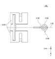
- FIG. 10 is a perspective view of the antenna section 200B according to Embodiment 2.
- FIG. An antenna unit 200B according to the second embodiment is the same as the vehicle-mounted antenna device 10B according to the second embodiment except for the following points.
- the antenna section 200B according to Embodiment 2 does not include the antenna base 110 and the antenna case 120.
- An antenna section 200B according to the second embodiment includes a monopole antenna 210B, a first parasitic element 222B, and a second parasitic element 224B in the same manner as the in-vehicle antenna device 10B according to the second embodiment.
- FIG. 10 illustrates the configuration of the monopole antenna 210B, the first parasitic element 222B, and the second parasitic element 224B that are not housed in the housing space 122.
- FIG. FIG. 10 shows the directivity of the monopole antenna 210B housed in the housing space 122 as shown in FIG. 9 and the directivity of the monopole antenna 210B not housed in the housing space 122 as shown in FIG. It is a figure for comparison.
- FIG. 11 is a graph showing the in-horizontal directivity of the monopole antenna 210B in the vehicle-mounted antenna device 10B according to the second embodiment.
- FIG. 12 is a graph showing the horizontal directivity of the monopole antenna 210B in the antenna section 200B according to the second embodiment.
- the graphs of FIGS. 11 and 12 show the horizontal directivity of 5900 MHz, which is the frequency used in the monopole antenna 210B.
- the conditions of the antenna unit 10A for the first embodiment and the conditions of the antenna unit 200A according to the first embodiment shown in FIG. 6 were the same. That is, the height of the monopole antenna 210B in the third direction Z was set to 25.3 mm. The height of the first parasitic element 222B and the second parasitic element 224B in the third direction Z was 47 mm.
- the monopole antenna 210B, the first parasitic element 222B and the second parasitic element 224B are arranged in the second Y direction.
- the monopole antenna 210B When viewed from the third direction Z, the monopole antenna 210B is positioned on the imaginary centerline LXB.
- the first parasitic element 222B and the second parasitic element 224B were positioned at equal distances from the monopole antenna 210B.
- the distance in the second direction Y between the first parasitic element 222B and the second parasitic element 224B was set to 21 mm.
- the distance in the first direction X from the front end of the antenna case 120 to the monopole antenna 210B, the first parasitic element 222B and the second parasitic element 224B was 110 mm.
- the directivity of the monopole antenna 210B is near 0° ⁇ 30° and 180° ⁇ 30°. It is approximately 9 dBi to 10 dBi in the vicinity, and approximately 8 dBi in the vicinity of 90° ⁇ 30° and 270° ⁇ 30°. Therefore, when the monopole antenna 210B is not accommodated in the accommodation space 122, the first parasitic element 222B and the second parasitic element 224B direct the monopole antenna 210B in the positive and negative directions of the first direction X. It can be said that the directivity of the monopole antenna 210B in the positive and negative directions of the second direction Y is enhanced.
- the directivity of the monopole antenna 210B is about 8dBi to 11dBi at around 0° ⁇ 30°. It is about 8dBi to 10dBi near 90° ⁇ 30° and 9270° ⁇ 30°.
- the first parasitic element 222B and the second parasitic element 224B change the directivity of the monopole antenna 210B in the positive direction of the first direction X to It can be said that the directivity of the monopole antenna 210B in the positive and negative directions of the second direction Y is stronger than that of the monopole antenna 210B.
- the directivity in the positive direction and the negative direction in the first direction X of the monopole antenna 210B according to Embodiment 2, which is not accommodated in the accommodation space 122, is The directivity in the positive and negative directions in the first direction X of the single monopole antenna 210K according to Comparative Example 1, which is not housed in the housing space 122, is stronger.
- the positive directivity of the monopole antenna 210B according to the embodiment in the state accommodated in the accommodation space 122 in the first direction X is in the accommodation space 122. It is stronger than the positive directivity in the first direction X of the single monopole antenna 210K according to Comparative Example 1 in the accommodated state.
- the configurations of the monopole antenna 210B, the first parasitic element 222B and the second parasitic element 224B are not limited to the configuration described using the second embodiment.
- the in-vehicle antenna device 10B may be a compound antenna having an antenna other than the monopole antenna 210B.
- the first parasitic element 222B and the second parasitic element 224B may be shifted with respect to the virtual intersection line LYB according to the deviation of the monopole antenna 210B from the virtual center line LXB.
- the directivity of the monopole antenna 210B in at least one of the positive direction and the negative direction of the first direction X can be changed to The directivity of the monopole antenna 210B in at least one of the positive direction and the negative direction of the two Y directions can be strengthened.
- the monopole antenna 210B may be arranged to be deviated to the provisional front side or rear side with respect to the imaginary intersection line LYB.
- the monopole antenna 210B may be arranged to be deviated to the provisional front side or rear side with respect to the imaginary intersection line LYB.
- the directivity of the monopole antenna 210B in the positive direction of the first direction X is the negative direction of the first direction X. It can be stronger than the directivity of monopole antenna 210B in a direction.
- the directivity of the monopole antenna 210B in the negative direction of the first direction X is the positive direction of the first direction X. It can be stronger than the directivity of monopole antenna 210B in a direction.
- only one parasitic element may be provided for one monopole antenna 210B.
- a parasitic element is arranged in the direction crossing the longitudinal direction of the antenna case 120 with respect to the monopole antenna 210B.
- the monopole antenna 210B and the parasitic element are arranged in a direction crossing the longitudinal direction of the antenna case 120.
- the directivity of monopole antenna 210B in the longitudinal direction of antenna case 120 can be made stronger than the directivity of monopole antenna 210B in a direction different from the longitudinal direction of antenna case 120 .
- the monopole antenna 210B and the parasitic element may be arranged in a direction substantially perpendicular to the longitudinal direction of the antenna case 120.
- the monopole antenna 210B in the longitudinal direction of the antenna case 120 directivity can be further strengthened.
- three or more parasitic elements may be provided for one monopole antenna 210B.
- four parasitic elements are arranged at the four vertices of a quadrangle having two sides parallel to the first direction X and two sides parallel to the second direction Y.
- the monopole antenna 210B may be arranged at the center of the square.
- the directivity of the monopole antenna 210B in one direction can be made stronger than the directivity of the monopole antenna 210B in at least one of the positive direction and the negative direction of the second Y direction.
- FIG. 13 is a perspective view of a vehicle-mounted antenna device 10C according to Embodiment 3.
- FIG. A vehicle-mounted antenna device 10C according to Embodiment 3 is the same as the vehicle-mounted antenna device 10B according to Embodiment 2, except for the following points.
- a vehicle-mounted antenna device 10C according to Embodiment 3 includes a monopole antenna 210C, a first parasitic element 222C, and a second parasitic element 224C.
- a monopole antenna 210C according to the third embodiment is a quarter-wave monopole antenna. Specifically, the wavelength of the frequency used in the monopole antenna 210C is ⁇ C . The length of the monopole antenna 210C in the third direction Z is approximately equal to 1/4 times the wavelength ⁇ C . When viewed from the third direction Z, the monopole antenna 210C is positioned on the imaginary centerline LXC.
- the first parasitic element 222 ⁇ /b>C and the second parasitic element 224 ⁇ /b>C are not grounded with respect to the ground plane 20 .
- the length in the third direction Z of the first parasitic element 222C and the length in the third direction Z of the second parasitic element 224C are longer than the length in the third direction Z of the monopole antenna 210C.
- the length of the first parasitic element 222C in the third direction Z and the length of the second parasitic element 224C in the third direction Z are substantially equal to 1/2 times the wavelength ⁇ C .
- one of the first parasitic element 222 ⁇ /b>C and the second parasitic element 224 ⁇ /b>C may be grounded to the ground plane 20 . That is, at least one of the first parasitic element 222 ⁇ /b>C and the second parasitic element 224 ⁇ /b>C may not be grounded with respect to the ground plane 20 .
- the monopole antenna 210C, the first parasitic element 222C and the second parasitic element 224C are positioned on the virtual intersection line LYC. Therefore, the monopole antenna 210C and the first parasitic element 222C are arranged in a direction crossing the longitudinal direction of the antenna case 120. As shown in FIG. The monopole antenna 210C and the second parasitic element 224C are arranged in a direction crossing the longitudinal direction of the antenna case 120. As shown in FIG. Specifically, the first parasitic element 222C is located on the right side of the virtual center line LXC. Thus, the first parasitic element 222C is positioned between the right inner wall of the antenna case 120 and the monopole antenna 210C.
- the second parasitic element 224C is located on the left side with respect to the imaginary center line LXC. Thereby, the second parasitic element 224C is located between the left inner wall of the antenna case 120 and the monopole antenna 210C.
- the distance in the second direction Y between the first parasitic element 222C and the second parasitic element 224C is the length of the first parasitic element 222C in the third direction Z and the distance in the third direction Z of the second parasitic element 224C. is shorter than the length of Specifically, in the third embodiment, the distance in the second direction Y between the first parasitic element 222C and the second parasitic element 224C is substantially equal to 1/4 times the wavelength ⁇ C . Also, the first parasitic element 222C and the second parasitic element 224C are located at approximately the same distance from the monopole antenna 210C.
- the first parasitic element 222C and the second parasitic element 224C reflect radio waves radiated from the monopole antenna 210C. It can operate as a reflective element. Therefore, it is possible to enhance the directivity of the monopole antenna 210B in a desired direction.
- the length of the monopole antenna 210C in the third direction Z, the length of the first parasitic element 222C in the third direction Z, and the length of the second parasitic element 224D in the third direction Z can be shortened. Therefore, the monopole antenna 210C, the first parasitic element 222C, and the second parasitic element 224C can be arranged at a lower height in the antenna case 120 than in the second embodiment. Specifically, the monopole antenna 210C, the first parasitic element 222C, and the second parasitic element 224C can be arranged on the front side of the antenna case 120 compared to the second embodiment.
- the distance in the second direction Y between the first parasitic element 222C and the second parasitic element 224C can be shortened compared to the second embodiment. Therefore, compared to the second embodiment, the space in the second direction Y required for arranging the monopole antenna 210C, the first parasitic element 222C and the second parasitic element 224C can be made smaller.
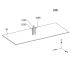
- FIG. 14 is a perspective view of an antenna section 200C according to Embodiment 3.
- FIG. An antenna unit 200C according to Embodiment 3 is the same as the in-vehicle antenna device 10C according to Embodiment 3, except for the following points.
- the antenna section 200C according to Embodiment 3 does not include the antenna base 110 and the antenna case 120.
- An antenna section 200C according to the third embodiment includes a monopole antenna 210C, a first parasitic element 222C, and a second parasitic element 224C in the same manner as the vehicle-mounted antenna device 10C according to the third embodiment.
- the monopole antenna 210C, the first parasitic element 222C and the second parasitic element 224C are housed in the housing space 122. As shown in FIG.
- FIG. 14 illustrates the configuration of the monopole antenna 210C, the first parasitic element 222C and the second parasitic element 224C which are not housed in the housing space 122.
- FIG. 14 shows the directivity of the monopole antenna 210C housed in the housing space 122 as shown in FIG. 13 and the directivity of the monopole antenna 210C not housed in the housing space 122 as shown in FIG. It is a figure for comparison.
- FIG. 15 is a graph showing the in-horizontal directivity of the monopole antenna 210C in the vehicle-mounted antenna device 10C according to the third embodiment.
- FIG. 16 is a graph showing the horizontal directivity of the monopole antenna 210C in the antenna section 200C according to the third embodiment.
- the graphs of FIGS. 15 and 16 show the horizontal directivity of 5900 MHz, which is the frequency used in the monopole antenna 210C.
- the conditions of the in-vehicle antenna device 10C according to Embodiment 3 shown in FIG. 15 and the conditions of the antenna unit 200C according to Embodiment 3 shown in FIG. The same conditions as those of the antenna device 10B and the conditions of the antenna unit 200B according to the second embodiment shown in FIG. 12 were used. That is, the height of the monopole antenna 210C in the third direction Z was set to 13 mm. The height of the first parasitic element 222C and the second parasitic element 224C in the third direction Z was 24 mm.
- the monopole antenna 210C, the first parasitic element 222C and the second parasitic element 224C are arranged in the second Y direction.
- the monopole antenna 210C When viewed from the third direction Z, the monopole antenna 210C is positioned on the imaginary centerline LXC.
- the first parasitic element 222C and the second parasitic element 224C were positioned at equal distances from the monopole antenna 210C.
- the distance in the second direction Y between the first parasitic element 222C and the second parasitic element 224C was 11 mm.
- the distance in the first direction X from the front end of the antenna case 120 to the monopole antenna 210C, the first parasitic element 222C and the second parasitic element 224C was set to 70 mm.
- the directivity of the monopole antenna 210C is near 0° ⁇ 30° and 180° ⁇ 30°. It is about 6dBi to 9dBi in the vicinity, and about -1dBi to 1dBi in the vicinity of 90° ⁇ 30° and 270° ⁇ 30°. Therefore, when the monopole antenna 210C is not accommodated in the accommodation space 122, the first parasitic element 222C and the second parasitic element 224C direct the monopole antenna 210C in the positive and negative directions of the first direction X. It can be said that the directivity of the monopole antenna 210C in the positive and negative directions of the second direction Y is enhanced.
- the directivity of the monopole antenna 210C is approximately 5dBi to 9dBi at around 0° ⁇ 30°. It is about 2dBi to 10dBi near 180° ⁇ 30°, and about 4dBi to 6dBi near 90° ⁇ 30° and 270° ⁇ 30°. Therefore, when the monopole antenna 210C is accommodated in the accommodation space 122, the first parasitic element 222C and the second parasitic element 224C direct the monopole antenna 210C in the positive and negative directions of the first direction X. It can be said that the directivity of the monopole antenna 210C in the positive and negative directions of the second direction Y is enhanced.
- the directivity of the monopole antenna 210C according to Embodiment 3, which is not accommodated in the accommodation space 122, in the second direction Y in the positive direction and the negative direction is It is weaker than the directivity in the positive and negative directions in the second direction Y of the single monopole antenna 210K according to Comparative Example 1 when it is not housed in the housing space 122 .
- the directivity in the positive direction and the negative direction in the first direction X of the monopole antenna 210C according to Embodiment 3 in the state not accommodated in the accommodation space 122 is the same as that in Comparative Example 1 in the state not accommodated in the accommodation space 122. is stronger than the directivity in the positive and negative directions in the first direction X of the single monopole antenna 210K.
- the directivity of the monopole antenna 210C according to Embodiment 3 in the state accommodated in the accommodation space 122 in the second direction Y in the positive direction and the negative direction is It is weaker than the directivity in the positive and negative directions in the second direction Y of the single monopole antenna 210K according to Comparative Example 1 in the state accommodated in the accommodation space 122 .
- the directivity in the positive direction and the negative direction in the first direction X of the monopole antenna 210C according to Embodiment 3 in the state accommodated in the accommodation space 122 is the same as that in Comparative Example 1 in the state accommodated in the accommodation space 122. is stronger than the directivity in the positive and negative directions in the first direction X of the single monopole antenna 210K.
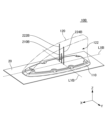
- FIG. 17 is a perspective view of a vehicle-mounted antenna device 10D according to Embodiment 4.
- FIG. A vehicle-mounted antenna device 10D according to Embodiment 4 is the same as the vehicle-mounted antenna device 10A according to Embodiment 1, except for the following points.
- a vehicle-mounted antenna device 10D according to Embodiment 4 includes a monopole antenna 210D, a first parasitic element 222D and a second parasitic element 224D.
- the monopole antenna 210D, the first parasitic element 222D and the second parasitic element 224D are housed in the housing space 122. As shown in FIG.
- a monopole antenna 210D according to the fourth embodiment is a half-wave monopole antenna. Specifically, the monopole antenna 210 ⁇ /b>D is provided on the upper surface side of the base plate 20 . Monopole antenna 210D is arranged substantially perpendicular to ground plane 20 . A lower end of the monopole antenna 210D facing the ground plane 20 serves as a feeding portion of the monopole antenna 210D. The wavelength of the frequency used in the monopole antenna 210D is ⁇ D . The length of the monopole antenna 210D in the third direction Z is approximately equal to 1/2 times the wavelength ⁇ D .
- the monopole antenna 210D When viewed from the third direction Z, the monopole antenna 210D is positioned on the imaginary centerline LXD.
- the imaginary center line LXD passes in the first direction X through substantially the center of the accommodation space 122 in the second direction Y. As shown in FIG.
- the first parasitic element 222D and the second parasitic element 224D are grounded to the ground plane 20. Specifically, the lower end of the first parasitic element 222D and the lower end of the second parasitic element 224D are connected to the ground plane 20 . However, one of the first parasitic element 222 ⁇ /b>D and the second parasitic element 224 ⁇ /b>D may be ungrounded with respect to the ground plane 20 . That is, at least one of the first parasitic element 222 ⁇ /b>D and the second parasitic element 224 ⁇ /b>D may be grounded to the ground plane 20 .
- the length in the third direction Z of the first parasitic element 222D and the length in the third direction Z of the second parasitic element 224D are shorter than the length in the third direction Z of the monopole antenna 210D. Also, the length of the first parasitic element 222D in the third direction Z and the length of the second parasitic element 224D in the third direction Z are longer than 1/4 times the wavelength ⁇ D .
- the first parasitic element 222D and the second parasitic element 224D are located on both sides in the first direction X with respect to the virtual intersection line LYD.
- the imaginary intersection line LYD intersects the imaginary centerline LXD and passes through the monopole antenna 210D in the second direction Y. Therefore, the monopole antenna 210D and the first parasitic element 222D are arranged along the longitudinal direction of the antenna case 120.
- Monopole antenna 210D and second parasitic element 224D are arranged along the longitudinal direction of antenna case 120 .
- the first parasitic element 222D is located on the front side with respect to the virtual intersection line LYD.
- the first parasitic element 222D is positioned between the front inner wall of the antenna case 120 and the monopole antenna 210D.
- the second parasitic element 224D is located on the rear side with respect to the virtual intersection line LYD. Thereby, the second parasitic element 224D is located between the rear inner wall of the antenna case 120 and the monopole antenna 210D.
- the first parasitic element 222D and the second parasitic element 224D can operate as inductive elements that induce radio waves radiated from the monopole antenna 210D. Therefore, the directivity of monopole antenna 210D in a desired direction can be enhanced.
- the first parasitic element 222D and the second parasitic element 224D change the directivity of the monopole antenna 210D in at least one of the positive and negative directions in the first direction X to the positive direction in the second direction Y and the directivity of the monopole antenna 210D in at least one of the negative direction.
- the monopole antenna 210D, the first parasitic element 222D and the second parasitic element 224D are arranged in a direction substantially parallel to the first direction X. Specifically, when viewed from the third direction Z, the monopole antenna 210D, the first parasitic element 222D and the second parasitic element 224D are positioned on the virtual center line LXD.
- the second direction The directivity of the monopole antenna 210D in at least one of the positive direction and the negative direction of Y can be further weakened, and the directivity of the monopole antenna 210D in at least one of the positive direction and the negative direction of the first direction X can be further strengthened. can be done.
- the distance in the first direction X between the first parasitic element 222D and the second parasitic element 224D is equal to the length in the third direction Z of the first parasitic element 222D and the length of the second parasitic element 224D is shorter than the length in the third direction Z of , and is substantially equal to 1/4 times the wavelength ⁇ D .
- the first parasitic element 222D and the second parasitic element 224D are located at substantially equal distances from the monopole antenna 210D. Also, the length in the third direction Z of the first parasitic element 222D and the length in the third direction Z of the second parasitic element 224D are substantially equal to each other. However, the arrangement and dimensions of the first parasitic element 222D and the second parasitic element 224D are not limited to the arrangement and dimensions according to the fourth embodiment. For example, the distance between monopole antenna 210D and first parasitic element 222D and the distance between monopole antenna 210D and second parasitic element 224D may be different.
- the length in the third direction Z of the first parasitic element 222D and the length in the third direction Z of the second parasitic element 224D may be different from each other.
- the directivity of the monopole antenna 210D in the first direction X can be enhanced.
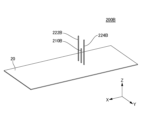
- FIG. 18 is a perspective view of an antenna section 200D according to Embodiment 4.
- FIG. An antenna unit 200D according to Embodiment 4 is the same as the in-vehicle antenna device 10D according to Embodiment 4, except for the following points.
- the antenna section 200D according to Embodiment 4 does not include the antenna base 110 and the antenna case 120.
- An antenna section 200C according to the fourth embodiment includes a monopole antenna 210D, a first parasitic element 222D and a second parasitic element 224D in the same manner as the vehicle-mounted antenna device 10D according to the fourth embodiment.
- FIG. 18 illustrates the configuration of the monopole antenna 210D, the first parasitic element 222D and the second parasitic element 224D that are not housed in the housing space 122.
- FIG. FIG. 18 shows the directivity of the monopole antenna 210D housed in the housing space 122 as shown in FIG. 17 and the directivity of the monopole antenna 210D not housed in the housing space 122 as shown in FIG. It is a figure for comparison.
- FIG. 19 is a graph showing the horizontal plane directivity of the monopole antenna 210D in the vehicle-mounted antenna device 10D according to the fourth embodiment.
- FIG. 20 is a graph showing the in-horizontal directivity of the monopole antenna 210D in the antenna section 200D according to the fourth embodiment.
- the graphs of FIGS. 19 and 20 show the horizontal directivity of 5900 MHz, which is the frequency used in the monopole antenna 210D.
- the conditions of the antenna unit 10A for the first embodiment and the conditions of the antenna unit 200A according to the first embodiment shown in FIG. 6 were the same. That is, the height of the monopole antenna 210D in the third direction Z was set to 28.5 mm. The height of the first parasitic element 222D and the second parasitic element 224D in the third direction Z was 20 mm.
- the monopole antenna 210D, the first parasitic element 222D and the second parasitic element 224D are positioned on the imaginary center line LXD.
- the first parasitic element 222D and the second parasitic element 224D were positioned at equal distances from the monopole antenna 210D.
- the distance in the first direction X between the first parasitic element 222D and the second parasitic element 224D was 11 mm.
- the distance in the first direction X from the front end of antenna case 120 to monopole antenna 210D was 70 mm.
- the directivity of the monopole antenna 210D is near 0° ⁇ 30° and 180° ⁇ 30°. It is about 7dBi in the vicinity, and about 5dBi to 6dBi in the vicinity of 90° ⁇ 30° and 270° ⁇ 30°. Therefore, when the monopole antenna 210D is not accommodated in the accommodation space 122, the first parasitic element 222D and the second parasitic element 224D direct the monopole antenna 210D in the positive and negative directions of the first direction X. It can be said that the directivity of the monopole antenna 210D in the positive and negative directions of the second direction Y is enhanced.
- the directivity of the monopole antenna 210D is about 5dBi to 8dBi at around 0° ⁇ 30°. It is about 4dBi to 9dBi near 180° ⁇ 30°, and about 5dBi to 7dBi near 90° ⁇ 30° and 270° ⁇ 30°. Therefore, when the monopole antenna 210D is accommodated in the accommodation space 122, the first parasitic element 222D and the second parasitic element 224D direct the monopole antenna 210D in the positive and negative directions of the first direction X. It can be said that the directivity of the monopole antenna 210D in the positive and negative directions of the second direction Y is enhanced.
- the directivity of the monopole antenna 210D according to Embodiment 4, which is not accommodated in the accommodation space 122, in the second direction Y in the positive direction and the negative direction is It is weaker than the directivity in the positive and negative directions in the second direction Y of the single monopole antenna 210K according to Comparative Example 1 when it is not housed in the housing space 122 .
- the directivity of the monopole antenna 210D according to Embodiment 4 in the state accommodated in the accommodation space 122 in the positive direction and the negative direction in the second direction Y is It is weaker than the directivity in the positive and negative directions in the second direction Y of the single monopole antenna 210K according to Comparative Example 1 in the state accommodated in the accommodation space 122 .
- the directivity in the negative direction of the first direction X of the monopole antenna 210D according to the fourth embodiment accommodated in the accommodation space 122 is the same as that of the monopole antenna 210D according to the comparative example 1 accommodated in the accommodation space 122. It is stronger than the negative directivity of the first direction X of one monopole antenna 210K.
- the configurations of the monopole antenna 210D, the first parasitic element 222D and the second parasitic element 224D are not limited to the configurations described in the fourth embodiment.
- At least one of the first parasitic element 222D and the second parasitic element 224D may be shifted to the right or left with respect to the virtual center line LXD.
- the monopole antenna 210D may be shifted to the right or left of the imaginary centerline LXD.
- the positive and negative can be made stronger than the directivity of the monopole antenna 210D in at least one of the positive direction and the negative direction of the second direction Y.
- only one parasitic element may be provided for one monopole antenna 210D.
- a parasitic element is arranged on the side of the antenna case 120 in the longitudinal direction (for example, the positive direction of the first direction X) with respect to the monopole antenna 210D.
- the monopole antenna 210 ⁇ /b>D and the parasitic element are thereby arranged along the longitudinal direction of the antenna case 120 . Therefore, the directivity of monopole antenna 210D in the longitudinal direction of antenna case 120 can be made stronger than the directivity of monopole antenna 210D in a direction different from the longitudinal direction of antenna case 120 .
- three or more parasitic elements may be provided for one monopole antenna 210D.
- four parasitic elements are arranged at the four vertices of a quadrangle having two sides parallel to the first direction X and two sides parallel to the second direction Y. and the monopole antenna 210D may be arranged at the center of the square.
- the directivity of the monopole antenna 210D in one direction can be made stronger than the directivity of the monopole antenna 210D in at least one of the positive direction and the negative direction of the second Y direction.
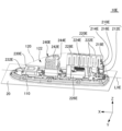
- FIG. 21 is a perspective view of a vehicle-mounted antenna device 10E according to Embodiment 5.
- FIG. 22 is an enlarged top view of a collinear array antenna 210E and a pair of first capacitive loading elements 222E in a vehicle-mounted antenna device 10E according to Embodiment 5.
- FIG. The vehicle-mounted antenna device 10E according to Embodiment 5 is the same as the vehicle-mounted antenna device 10B according to Embodiment 2 or the vehicle-mounted antenna device 10C according to Embodiment 3, except for the following points.
- a vehicle-mounted antenna device 10E according to Embodiment 5 is a composite antenna device.
- the in-vehicle antenna device 10E includes a collinear array antenna 210E, an AM/FM (Amplitude Modulation/Frequency Modulation) antenna 220E, a GNSS (Global Navigation Satellite System) antenna 230E, and a DAB (Digital Audio Brochure adcast) antenna 240E ing.
- the collinear array antenna 210E, the AM/FM antenna 220E, the GNSS antenna 230E and the DAB antenna 240E are housed in the housing space 122 of the antenna case 120.
- the collinear array antenna 210E is an antenna for performing V2X communication. As shown in FIG. 21, collinear array antenna 210E is arranged on the rear side of antenna base 110 . As shown in FIG. 21, the length of the antenna case 120 in the first direction X is longer than the length of the antenna case 120 in the second direction Y. As shown in FIG. Therefore, the directivity of the collinear array antenna 210E in at least one of the forward direction and the rearward direction can be made stronger than the directivity of the collinear array antenna 210E in the second Y direction. As shown in FIGS. 21 and 22, the collinear array antenna 210E is positioned on the imaginary centerline LXE of the antenna base 110 when viewed from the third direction Z. As shown in FIGS.
- the directivity of the collinear array antenna 210E is affected by the inner wall of the antenna case 120 on the right side of the accommodation space 122
- the directivity of the collinear array antenna 210E is affected by the inner wall of the antenna case 120 on the left side of the accommodation space 122, can reduce the difference between
- the wavelength of the frequency used in the collinear array antenna 210E is ⁇ E .
- the collinear array antenna 210E has a first straight portion 212E, a second straight portion 214E and an annular portion 216E.
- the first straight portion 212E, the second straight portion 214E, and the annular portion 216E are conductors such as metal.
- the first straight portion 212E is a substantially linear antenna element. As shown in FIG. 21, the first linear portion 212E is arranged substantially perpendicular to the base plate 20. As shown in FIG. A lower end portion of the first straight portion 212E serves as a power supply portion.
- the length of the first straight portion 212E in the third direction Z is adjusted to an appropriate length according to the wavelength ⁇ E of the frequency used in the collinear array antenna 210E. In Embodiment 5, the length of the first straight portion 212E in the third direction Z is approximately equal to 1/2 times the wavelength ⁇ E , for example.
- the length of the first linear portion 212E in the third direction Z may be 3/8 times or more and 5/8 times or less of the wavelength ⁇ E .
- the second straight portion 214E is a substantially linear antenna element. As shown in FIG. 21, the second linear portion 214E is inclined forward with respect to the third direction Z. As shown in FIG. The upper end of the second linear portion 214E is bent forward and substantially parallel to the first direction X. As shown in FIG. Therefore, the electrical length of the collinear array antenna 210E can be increased and the height can be reduced compared to the case where the upper end portion of the second straight portion 214E is not bent. However, the upper end portion of the second straight portion 214E may not be bent.
- the length of the second straight portion 214E in the third direction Z when the second straight portion 214E extends parallel to the third direction Z without bending the upper end portion of the second straight portion 214E is equal to the length of the first straight portion 214E. It is substantially equal to the length of 212E in the third direction Z.
- the length of the second straight portion 214E may be, for example, 95% or more and 105% or less of the length of the first straight portion 212E.
- the annular portion 216E is connected to the upper end of the first straight portion 212E and the lower end of the second straight portion 214E. As shown in FIGS. 21 and 22, when viewed from the third direction Z, the annular portion 216E is wound around in a substantially annular shape. The phase of the first linear portion 212E and the phase of the second linear portion 214E are matched by the annular portion 216E.
- the collinear array antenna 210E is held by a first holder 218E.
- the first holder 218E is arranged on the upper surface side of the antenna base 110 .
- the first holder 218E is made of resin, that is, dielectric. Therefore, the wavelength of radio waves transmitted and received in the collinear array antenna 210E can be shortened by the dielectric material forming the first holder 218E. Therefore, the height of the collinear array antenna 210E can be reduced compared to the case where such wavelength shortening does not occur.
- the AM/FM antenna 220E is an antenna for receiving radio waves of AM/FM radio broadcasting.
- the frequencies used in AM/FM antenna 220E are different from the frequencies used in collinear array antenna 210E.
- AM/FM antenna 220E has a pair of first capacitive loading element 222E and helical element 224E.
- each first capacitive loading element 222E is arranged on both sides of the imaginary center line LXE in the second direction Y when viewed from the third direction Z.
- Each first capacitive loading element 222E is made of sheet metal, for example.
- Each first capacitive loading element 222E has a meandering shape. Specifically, each first capacitive-loading element 222E is folded multiple times in the third direction Z from the front end to the rear end of each first capacitive-loading element 222E when viewed from the second direction Y. .
- the shape of the first capacitive loading element 222E is not limited to this example.
- the upper end of the helical element 224E is electrically connected to the pair of first capacitive loading elements 222E.
- the lower end of the helical element 224E is electrically connected to the amplifier board 226E.
- the amplifier board 226E is arranged on the upper surface side of the antenna base 110 .
- the pair of first capacitive loading elements 222E are held by a second holder 228E.
- the second holder 228E is arranged on the upper surface side of the antenna base 110 .
- the rear ends of the pair of first capacitive loading elements 222E are pulled out rearward from the rear ends of the second holders 228E.
- the upper end of the second linear portion 214E is positioned between the rear ends of the pair of first capacitive load elements 222E in the second direction Y. ing. Therefore, the rear end portion of the right first capacitive loading element 222E is positioned between the right inner wall of the antenna case 120 and the upper end portion of the second straight portion 214E.
- the rear end portion of the left first capacitive loading element 222E is positioned between the left inner wall of the antenna case 120 and the upper end portion of the second straight portion 214E.
- the first linear portion 212E and the annular portion 216E are arranged rearwardly with respect to the rear end portions of the pair of first capacitive loading elements 222E. It is located off.
- the pair of first capacitive loading elements 222E may operate as reflecting elements that reflect radio waves radiated from the collinear array antenna 210E. Therefore, in the fifth embodiment, compared to the case where the collinear array antenna 210E as a whole is shifted rearward from the rear end portions of the pair of first capacitive loading elements 222E as viewed from the third direction Z, the pair of first capacitive loading elements 222E The reflection of radio waves by the first capacitive loading element 222E can facilitate the induction of radio waves forward from the collinear array antenna 210E.
- the collinear The directivity of the array antenna 210E on the front side can be enhanced. Therefore, the directivity of the collinear array antenna 210E in a desired direction can be enhanced according to the relationship between the position of the collinear array antenna 210E and the position of the pair of first capacitive loading elements 222E.
- the upper end portion of the second linear portion 214E and the rear end portion of the pair of first capacitive loading elements 222E overlap in the second direction Y. Therefore, in the fifth embodiment, compared to the case where the upper end portion of the second linear portion 214E and the rear end portion of the pair of first capacitive loading elements 222E do not overlap in the second direction Y, the pair of first Radio waves can be easily guided forward from the collinear array antenna 210E by reflection of the radio waves by the capacitive loading element 222E.
- the collinear array antenna The directivity of the front side of 210E can be strengthened.
- the upper end portion of the second linear portion 214E and the rear end portion of the pair of first capacitive loading elements 222E do not have to overlap in the second direction Y.
- the upper end of the second straight portion 214E may be positioned below the lower ends of the rear end portions of the pair of first capacitive loading elements 222E.
- the first linear portion 212E and the annular portion 216E are shifted rearward from the rear end portions of the pair of first capacitive loading elements 222E. That is, when viewed from the third direction Z, a portion of the collinear array antenna 210E is shifted rearward from the rear end portions of the pair of first capacitive loading elements 222E. Therefore, compared to the case where the entire collinear array antenna 210E is positioned between the pair of first capacitive loading elements 222E in the second direction Y when viewed from the third direction Z, the pair of collinear array antennas 210E on the rear side is , the reflection of radio waves by the first capacitive loading element 222E can be reduced.
- the rear directivity of the collinear array antenna 210E is can be improved.
- the collinear array antenna 210E is arranged in the space existing between the pair of first capacitive loading elements 222E. Therefore, in the fifth embodiment, compared to the case where the entire collinear array antenna 210E is shifted rearward from the rear end portions of the pair of first capacitive loading elements 222E as viewed from the third direction Z, the in-vehicle The length in the first direction X of the antenna device 10E can be shortened.
- the rear end portions of the pair of first capacitive loading elements 222E extend to positions on both sides in the second direction Y of the upper end portion of the second linear portion 214E. Therefore, in the fifth embodiment, compared to the case where the rear end portions of the pair of first capacitive load elements 222E are shifted forward with respect to both sides in the second direction Y of the upper end portion of the second linear portion 214E, , the total length of each first capacitive loading element 222E can be increased.
- the AM/FM antenna 220E gain can be improved.
- the GNSS antenna 230E is an antenna for receiving GNSS radio waves.
- the GNSS antenna 230E is arranged on the upper surface side of the GNSS antenna substrate 232E.
- the antenna substrate 232E is arranged on the upper surface side of the antenna base 110 .
- the GNSS antenna 230E and the GNSS antenna board 232E are arranged on the front side of the antenna base 110 .
- the DAB antenna 240E is an antenna for receiving DAB radio waves.
- DAB antenna 240E has a second capacitive loading element 242E.
- the second capacitive loading element 242E is held by a third holder 244E.
- the DAB antenna 240E is positioned in the first direction X between the AM/FM antenna 220E and the GNSS antenna 230E.
- a vehicle-mounted antenna device 10E according to Embodiment 5 includes a collinear array antenna 210E as a V2X antenna.
- a collinear array antenna 210E as a V2X antenna.
- other antennas having linear antenna elements may be used instead of the collinear array antenna 210E.
- Another antenna is, for example, a monopole antenna that is substantially perpendicular to the ground plane 20 . In this example, when viewed from the third direction Z, at least a portion of the monopole antenna is positioned in the second direction Y between the pair of first capacitive loading elements 222E.
- a vehicle-mounted antenna device 10E according to Embodiment 5 includes an AM/FM antenna 220E.
- the vehicle-mounted antenna device 10E may include an antenna that operates only as an FM antenna instead of the AM/FM antenna 220E.
- This antenna also has a pair of first capacitive loading element and helical element, similar to AM/FM antenna 220E.
- At least a portion of the collinear array antenna 210E is positioned in the second direction Y between the pair of first capacitive loading elements when viewed from the third direction Z. As shown in FIG. Antennas that operate only as FM antennas may not have AM circuitry.
- FIG. 23 is an enlarged top view of a collinear array antenna 210E and a pair of first capacitive loading elements 222E in a vehicle-mounted antenna device 10E1 according to a modification.
- the vehicle-mounted antenna device 10E1 according to the modification is the same as the vehicle-mounted antenna device 10E according to the fifth embodiment except for the following points.
- the entire collinear array antenna 210E is located between the pair of first capacitive loading elements 222E in the second direction Y when viewed from the third direction Z.
- the pair of first capacitive loading elements 222E may operate as reflecting elements that reflect radio waves radiated from the collinear array antenna 210E.
- radio waves are reflected forward from the collinear array antenna 210E by the pair of first capacitive loading elements 222E on both sides of the collinear array antenna 210E in the second direction Y, as compared with the fifth embodiment. It can be made easier to induce. Therefore, in the modified example, compared with the fifth embodiment, the forward directivity of the collinear array antenna 210E can be further enhanced.
- the collinear array antenna 210E when viewed from the third direction Z, the collinear array antenna 210E is shifted rearward in the first direction X with respect to the center of the pair of first capacitive loading elements 222E. Therefore, compared to the case where the collinear array antenna 210E is arranged at or near the center of the pair of first capacitive loading elements 222E in the first direction X when viewed from the third direction Z, the rear side of the collinear array antenna 210E , the reflection of radio waves by the pair of first capacitive loading elements 222E can be reduced.
- the collinear array antenna 210E compared to the case where the collinear array antenna 210E is arranged at or near the center of the pair of first capacitive loading elements 222E in the first direction X when viewed from the third direction Z, the collinear array antenna 210E The directivity of the antenna 210E on the rear side can be improved.
- FIG. 24 is a graph showing the in-horizontal directivity of the collinear array antenna 210E in each of the vehicle-mounted antenna device 10E according to the fifth embodiment, the vehicle-mounted antenna device 10E1 according to the modified example, and the vehicle-mounted antenna device 10L according to the second comparative example.
- FIG. 25 is an enlarged top view of a collinear array antenna 210E and a pair of first capacitive loading elements 222E in a vehicle-mounted antenna device 10L according to Comparative Example 2.
- the horizontal plane directivity of the collinear array antenna 210E according to the fifth embodiment is indicated by a solid line.
- the in-horizontal directivity of the collinear array antenna 210E according to the modification is indicated by a dashed line.
- the horizontal directivity of collinear array antenna 210E according to Comparative Example 2 is indicated by a broken line.
- Each horizontal directivity in FIG. 24 indicates the horizontal directivity of collinear array antenna 210E when collinear array antenna 210E is housed in housing space 122.
- the numbers attached to the outer periphery of the graph indicate the direction (unit: °) in the horizontal plane. 180°, 0°, 270° and 90° are forward, backward, left and right respectively.
- the length from the front end to the rear end of the pair of first capacitive loading elements 222E is 80 mm in the fifth embodiment, 92 mm in the modified example, and 68 mm in the second comparative example.
- the upper end of the second linear portion 214E when viewed from the third direction Z, is located between the pair of first capacitive load elements 222E in the second direction Y.
- the first linear portion 212E is positioned 6 mm behind the rear end portions of the pair of first capacitive loading elements 222E.
- the entire collinear array antenna 210E is located between the pair of first capacitive loading elements 222E in the second direction Y when viewed from the third direction Z.
- the first linear portion 212E is positioned 5.5 mm forward with respect to the rear end portions of the pair of first capacitive loading elements 222E.
- Comparative Example 2 when viewed from the third direction Z, the entire collinear array antenna 210E is shifted rearward from the rear end portions of the pair of first capacitive loading elements 222E. When viewed from the third direction Z, the first linear portion 212E is positioned 17.5 mm behind the rear end portions of the pair of first capacitive loading elements 222E.
- Embodiment 5 and Comparative Example 2 are compared in FIG.
- the directivity at 120° and its periphery and the directivity at 240° and its periphery in Embodiment 5 are higher than the directivity at 120° and its periphery and the directivity at 240° and its periphery in Comparative Example 2. It's becoming The result is that when at least a portion of the collinear array antenna 210E as viewed in the third direction Z is positioned between the pair of first capacitive loading elements 222E in the second direction Y, the collinear array antenna 210E is shifted rearward with respect to the rear end of the first capacitive loading element 222E, it suggests that the directivity on the front side of the collinear array antenna 210E can be improved.
- the directivity at 120° and its periphery and the directivity at 240° and its periphery in the modified example are higher than the directivity at 120° and its periphery and the directivity at 240° and its periphery in Embodiment 5. ing.
- the collinear array antenna 210E as viewed from the third direction Z is positioned between the pair of first capacitive loading elements 222E in the second direction Y, the collinear array antenna 210E as viewed from the third direction Z
- the directivity on the front side of the collinear array antenna 210E can be improved compared to the case where a portion is shifted rearward with respect to the rear end of the first capacitive loading element 222E.
- the directivity at 0° and its periphery, the directivity at 45° and its periphery, and the directivity at 315° and its periphery in Embodiment 5 are the directivity at 0° and its periphery, 45° in the modified example. and the directivity at and around 315° and the directivity at and around 315°.
- the collinear array antenna 210E when a portion of the collinear array antenna 210E as viewed from the third direction Z is shifted rearward with respect to the rear end of the first capacitive loading element 222E, the collinear array antenna 210E is positioned between the pair of first capacitive loading elements 222E in the second direction Y, the directivity on the rear side of the collinear array antenna 210E can be improved.
- Aspect 1 is an antenna case having a longitudinal direction; a plurality of monopole antennas housed in the housing space of the antenna case; with The plurality of monopole antennas are an in-vehicle antenna device arranged in a direction intersecting the longitudinal direction.
- the radio waves radiated from each of the monopole antennas interfere with each other between the monopole antennas. This makes it possible to strengthen the directivity of the plurality of monopole antennas in the direction crossing the virtual line segment connecting two monopole antennas included in the plurality of monopole antennas. Therefore, it is possible to enhance the directivity of a plurality of monopole antennas in desired directions.
- Aspect 2 is The vehicle-mounted antenna device according to aspect 1, wherein the plurality of monopole antennas are arranged in a direction substantially perpendicular to the longitudinal direction.
- the directivity of the plurality of monopole antennas in the longitudinal direction of the antenna case compared to the case where the plurality of monopole antennas are arranged in a direction different from the direction substantially perpendicular to the longitudinal direction of the antenna case can be further strengthened.
- Aspect 3 is The on-vehicle use according to aspect 1 or 2, wherein the plurality of monopole antennas are positioned substantially symmetrically with respect to an imaginary line passing through the center of the housing space in a direction substantially parallel to the longitudinal direction. It is an antenna device. According to aspect 3, the influence of the directivity of the plurality of monopole antennas from the antenna case on one side of the virtual line in the accommodation space and the influence of the antenna case on the other side of the virtual line in the accommodation space on the plurality of monopole antennas It is possible to reduce the difference between the directivity of the pole antenna and the influence.
- Aspect 4 is The in-vehicle antenna device according to any one of aspects 1 to 3, wherein the length of the antenna case in the longitudinal direction of the vehicle in which the in-vehicle antenna device is mounted is longer than the length of the antenna case in the lateral direction of the vehicle. is. According to aspect 4, it is possible to strengthen the directivity of the monopole antenna in at least one of the forward direction and the rearward direction of the vehicle.
- Aspect 5 is Vehicle-mounted vehicle according to any one of modes 1 to 4, wherein the plurality of monopole antennas are positioned in the longitudinal direction at the center of the accommodation space or at a distance of 45% or less of the total length in the longitudinal direction from the center.
- Aspect 6 is an antenna case having a longitudinal direction; a monopole antenna housed in the housing space of the antenna case; a parasitic element accommodated in the accommodation space; with The monopole antenna and the parasitic element are arranged in a direction intersecting the longitudinal direction of the on-vehicle antenna device.
- the directivity of the monopole antenna in the longitudinal direction of the antenna case can be enhanced by operating the parasitic element as a reflecting element that reflects radio waves radiated from the monopole antenna. Therefore, it is possible to enhance the directivity of the monopole antenna in a desired direction. Also, the configuration of a monopole antenna can be simplified compared to the configuration of other antennas such as dipole antennas. Therefore, the vehicle-mounted antenna device can have a relatively simple configuration. (Aspect 7) Aspect 7 is The vehicle-mounted antenna device according to aspect 6, wherein the monopole antenna and the parasitic element are arranged in a direction substantially perpendicular to the longitudinal direction.
- Aspect 8 is The on-vehicle antenna device according to mode 6 or 7, wherein at least two of the parasitic elements are positioned on both sides of an imaginary line passing through the monopole antenna in a direction substantially parallel to the longitudinal direction. be. According to aspect 8, by operating at least two parasitic elements as reflecting elements that reflect radio waves radiated from the monopole antenna, the directivity of the monopole antenna in the longitudinal direction of the antenna case can be enhanced. .
- Aspect 9 is The on-vehicle antenna device according to any one of modes 6 to 8, wherein the at least two parasitic elements are arranged in a direction substantially perpendicular to the longitudinal direction.
- the directionality of the monopole antenna in the longitudinal direction of the antenna case is higher than when at least two parasitic elements are arranged in a direction different from the direction substantially perpendicular to the longitudinal direction of the antenna case. You can strengthen your sexuality.
- Aspect 10 is The vehicle-mounted antenna device according to any one of modes 6 to 9, wherein the parasitic element is ungrounded.
- the parasitic element can operate as a reflecting element that reflects radio waves radiated from the monopole antenna.
- Aspect 11 is 11.
- the directivity of the monopole antenna in the longitudinal direction of the antenna case can be enhanced in a state in which the parasitic element is positioned between the inner wall of the antenna case and the monopole antenna.
- Aspect 12 is The on-vehicle antenna device according to any one of modes 6 to 11, wherein the monopole antenna is positioned on a virtual line passing through the approximate center of the housing space in a direction substantially parallel to the longitudinal direction. is. According to aspect 12, the directivity of the monopole antenna is affected by the antenna case on one side of the virtual line in the accommodation space, and the directivity of the monopole antenna from the antenna case on the other side of the virtual line in the accommodation space.
- Aspect 13 is The vehicle-mounted antenna device according to any one of aspects 6 to 12, wherein the length of the antenna case in the front-rear direction of the vehicle in which the vehicle-mounted antenna device is mounted is longer than the length of the antenna case in the left-right direction of the vehicle. is. According to aspect 13, the directivity of the monopole antenna in at least one of the forward direction and the rearward direction of the vehicle can be enhanced.
- Aspect 14 is The in-vehicle antenna according to any one of aspects 6 to 13, wherein the monopole antenna is positioned in the longitudinal direction at the center of the accommodation space or at a distance of 45% or less of the total length in the longitudinal direction from the center. It is a device.
- Aspect 15 is an antenna case having a longitudinal direction; a monopole antenna housed in the housing space of the antenna case; a parasitic element accommodated in the accommodation space; with The monopole antenna and the parasitic element are arranged along the longitudinal direction of the on-vehicle antenna device.
- the directivity of the monopole antenna in the longitudinal direction of the antenna case can be enhanced by operating the parasitic element as an inductive element that induces radio waves radiated from the monopole antenna.
- Aspect 16 is 16.
- the directivity of the monopole antenna in the longitudinal direction of the antenna case can be enhanced by operating at least two parasitic elements as inductive elements that guide radio waves radiated from the monopole antenna. .
- Aspect 17 is 17.
- the orientation of the monopole antenna in the longitudinal direction of the antenna case You can strengthen your sexuality.
- Aspect 18 is 18.
- the parasitic element can operate as an inductive element that induces radio waves radiated from the monopole antenna.
- Aspect 19 is 19.
- the directivity of the monopole antenna in the longitudinal direction of the antenna case can be enhanced in a state in which the parasitic element is positioned between the inner wall of the antenna case and the monopole antenna.
- Aspect 20 is The on-vehicle antenna device according to any one of aspects 15 to 19, wherein the monopole antenna is positioned on a virtual line passing through a substantially center of the accommodation space in a direction substantially parallel to the longitudinal direction. is. According to aspect 20, the directivity of the monopole antenna is affected by the antenna case on one side of the virtual line in the accommodation space, and the directivity of the monopole antenna from the antenna case on the other side of the virtual line in the accommodation space.
- Aspect 21 is The in-vehicle antenna device according to any one of aspects 15 to 20, wherein the length of the antenna case in the longitudinal direction of the vehicle in which the in-vehicle antenna device is mounted is longer than the length of the antenna case in the lateral direction of the vehicle. is. According to aspect 21, the directivity of the monopole antenna in at least one of the forward direction and the rearward direction of the vehicle can be enhanced.
- Aspect 22 is The on-vehicle antenna according to any one of aspects 15 to 21, wherein the monopole antenna is positioned in the longitudinal direction at the center of the accommodation space or at a distance of 45% or less of the total length in the longitudinal direction from the center. It is a device.
- Aspect 23 is an antenna case having a longitudinal direction; An antenna element housed in the housing space of the antenna case; a pair of capacitive loading elements housed in the housing space and arranged in a direction crossing the longitudinal direction; with At least a portion of the antenna element is a vehicle-mounted antenna device positioned between the pair of capacitive loading elements.
- Aspect 24 is 24.
- the antenna element is shifted from the center of the capacitive loading element compared to the case where the antenna element is arranged at or near the center of the pair of capacitive loading elements in the longitudinal direction of the antenna case. It is possible to reduce the reflection of radio waves by the pair of capacitively-loaded elements on the side of the antenna. Therefore, according to aspect 24, the antenna element is displaced from the center of the capacitive-loading element compared to the case where the antenna element is arranged at or near the center of the pair of capacitive-loading elements in the longitudinal direction of the antenna case.
- Aspect 25 is 25.
- the pair of The reflection of radio waves by the capacitively loaded element can be reduced. Therefore, according to aspect 25, compared to the case where the entire antenna element is positioned between the pair of capacitive loading elements, the other part of the antenna element is shifted from the pair of capacitive loading elements. can improve the directivity of the antenna element.
- Aspect 26 is The vehicle-mounted vehicle according to any one of claims 23 to 25, wherein said at least part of said antenna element and at least part of said pair of capacitive loading elements overlap in a direction substantially perpendicular to said longitudinal direction. It is an antenna device for According to aspect 26, at least a portion of the antenna element and at least a portion of the pair of ridge-beam loading elements are substantially perpendicular to the longitudinal direction of the antenna case, as compared to non-overlapping cases where the pair of capacitive loading elements The reflection of radio waves from the antenna element can facilitate the induction of radio waves in the longitudinal direction of the antenna case. Therefore, according to aspect 26, the directivity of the antenna element in the longitudinal direction of the antenna case can be enhanced. (Aspect 27) Aspect 27 is 27.
- the on-vehicle antenna device according to any one of modes 23 to 26, wherein the antenna element is positioned on an imaginary line passing through substantially the center of the housing space in a direction substantially parallel to the longitudinal direction.
- the directivity of the antenna element is influenced by the antenna case on one side of the virtual line in the accommodation space, and the directivity of the antenna element is affected by the antenna case on the other side of the virtual line in the accommodation space. It is possible to reduce the difference between the influence received and the (Aspect 28)
- the vehicle-mounted antenna device according to any one of aspects 23 to 27, wherein the length of the antenna case in the front-rear direction of the vehicle in which the vehicle-mounted antenna device is mounted is longer than the length of the antenna case in the left-right direction of the vehicle. .
- the directivity of the antenna element in at least one of the forward direction and the rearward direction of the vehicle can be enhanced.
- 10A, 10B, 10C, 10D, 10E, 10E1, 10K, 10L Automotive antenna device 20 Base plate, 110 Antenna base, 120 Antenna case, 122 Storage space, 200A, 200B, 200C, 200D, 200K Antenna part, 210A Array antenna , 210B, 210C, 210D, 210K monopole antenna, 212A first monopole antenna, 214A second monopole antenna, 222B, 222C, 222D first parasitic element, 224B, 224C, 224D second parasitic element, 210E collinear Array antenna, 212E first straight part, 214E second straight part, 216E annular part, 218E first holder, 220E AM/FM antenna, 222E first capacitive loading element, 224E helical element, 226E amplifier board, 228E second holder, 230E GNSS antenna, 232E GNSS antenna substrate, 240E DAB antenna, 242E second capaci
Landscapes
- Engineering & Computer Science (AREA)
- Remote Sensing (AREA)
- Mechanical Engineering (AREA)
- Variable-Direction Aerials And Aerial Arrays (AREA)
- Details Of Aerials (AREA)
Priority Applications (3)
| Application Number | Priority Date | Filing Date | Title |
|---|---|---|---|
| JP2023556357A JPWO2023074490A1 (https=) | 2021-10-25 | 2022-10-19 | |
| CN202280070276.XA CN118140354A (zh) | 2021-10-25 | 2022-10-19 | 车载用天线装置 |
| US18/645,712 US20240283142A1 (en) | 2021-10-25 | 2024-04-25 | Vehicular antenna device |
Applications Claiming Priority (2)
| Application Number | Priority Date | Filing Date | Title |
|---|---|---|---|
| JP2021173607 | 2021-10-25 | ||
| JP2021-173607 | 2021-10-25 |
Related Child Applications (1)
| Application Number | Title | Priority Date | Filing Date |
|---|---|---|---|
| US18/645,712 Continuation-In-Part US20240283142A1 (en) | 2021-10-25 | 2024-04-25 | Vehicular antenna device |
Publications (1)
| Publication Number | Publication Date |
|---|---|
| WO2023074490A1 true WO2023074490A1 (ja) | 2023-05-04 |
Family
ID=86159381
Family Applications (1)
| Application Number | Title | Priority Date | Filing Date |
|---|---|---|---|
| PCT/JP2022/038896 Ceased WO2023074490A1 (ja) | 2021-10-25 | 2022-10-19 | 車載用アンテナ装置 |
Country Status (4)
| Country | Link |
|---|---|
| US (1) | US20240283142A1 (https=) |
| JP (1) | JPWO2023074490A1 (https=) |
| CN (1) | CN118140354A (https=) |
| WO (1) | WO2023074490A1 (https=) |
Citations (5)
| Publication number | Priority date | Publication date | Assignee | Title |
|---|---|---|---|---|
| JP2004147351A (ja) * | 2000-03-01 | 2004-05-20 | Matsushita Electric Ind Co Ltd | 無線通信端末用内蔵アンテナ |
| JP2005286801A (ja) * | 2004-03-30 | 2005-10-13 | Denso Corp | 車載アンテナ装置および車載アンテナ装置の搭載方法 |
| JP2012054915A (ja) * | 2010-08-06 | 2012-03-15 | Nippon Soken Inc | アンテナ構造及びダイバーシティアンテナ構造 |
| JP2015061098A (ja) * | 2013-09-17 | 2015-03-30 | アルプス電気株式会社 | アンテナ装置 |
| WO2017141635A1 (ja) * | 2016-02-19 | 2017-08-24 | 株式会社ヨコオ | アンテナ装置 |
-
2022
- 2022-10-19 CN CN202280070276.XA patent/CN118140354A/zh active Pending
- 2022-10-19 JP JP2023556357A patent/JPWO2023074490A1/ja active Pending
- 2022-10-19 WO PCT/JP2022/038896 patent/WO2023074490A1/ja not_active Ceased
-
2024
- 2024-04-25 US US18/645,712 patent/US20240283142A1/en active Pending
Patent Citations (5)
| Publication number | Priority date | Publication date | Assignee | Title |
|---|---|---|---|---|
| JP2004147351A (ja) * | 2000-03-01 | 2004-05-20 | Matsushita Electric Ind Co Ltd | 無線通信端末用内蔵アンテナ |
| JP2005286801A (ja) * | 2004-03-30 | 2005-10-13 | Denso Corp | 車載アンテナ装置および車載アンテナ装置の搭載方法 |
| JP2012054915A (ja) * | 2010-08-06 | 2012-03-15 | Nippon Soken Inc | アンテナ構造及びダイバーシティアンテナ構造 |
| JP2015061098A (ja) * | 2013-09-17 | 2015-03-30 | アルプス電気株式会社 | アンテナ装置 |
| WO2017141635A1 (ja) * | 2016-02-19 | 2017-08-24 | 株式会社ヨコオ | アンテナ装置 |
Non-Patent Citations (1)
| Title |
|---|
| YAMASAKI, MASAAKI; TSUKIJI, TAKEHIKO: "19-5 Widening the bandwidth of monopole antennas by parallel lines", PROCEEDINGS OF THE 2013 ITE ANNUAL CONVENTION; 2013/08/28 - 2013/08/30, INSTITUTE OF IMAGE INFORMATION AND TELEVISION ENGINEERS, JP, 29 August 2008 (2008-08-29), JP, pages 19 - 19-5-2, XP009545827, ISSN: 1343-1846, DOI: 10.11485/iteac.2008.0__19-5-1_ * |
Also Published As
| Publication number | Publication date |
|---|---|
| JPWO2023074490A1 (https=) | 2023-05-04 |
| US20240283142A1 (en) | 2024-08-22 |
| CN118140354A (zh) | 2024-06-04 |
Similar Documents
| Publication | Publication Date | Title |
|---|---|---|
| JP7399239B2 (ja) | 車載用アンテナ装置 | |
| JP5278673B2 (ja) | アンテナ装置および複合アンテナ装置 | |
| US20190280365A1 (en) | Vehicle integrated antenna with enhanced beam steering | |
| EP3040736A1 (en) | Radar antenna assembly with panoramic detection | |
| JP6411593B1 (ja) | 車載用アンテナ装置 | |
| US7079078B2 (en) | Patch antenna apparatus preferable for receiving ground wave and signal wave from low elevation angle satellite | |
| JP6792406B2 (ja) | 車載用アンテナ装置 | |
| WO2012077389A1 (ja) | アンテナ装置 | |
| JP4141979B2 (ja) | 自動車用高周波ガラスアンテナ | |
| KR102566812B1 (ko) | 차량 일체형 안테나 | |
| CN110574233A (zh) | 天线装置 | |
| WO2019065531A1 (ja) | パッチアンテナ及びアンテナ装置 | |
| JP7765978B2 (ja) | アンテナ装置 | |
| CN210040534U (zh) | 车载天线装置 | |
| CN112186355A (zh) | 天线模块及车机装置 | |
| US20130135161A1 (en) | Antenna device | |
| WO2006092862A1 (ja) | 導波管スロットアレーアンテナ装置 | |
| WO2023074490A1 (ja) | 車載用アンテナ装置 | |
| WO2012127734A1 (ja) | アンテナ装置 | |
| JP5032910B2 (ja) | パルスレーダ用アンテナ装置 | |
| JP4021814B2 (ja) | 車載アンテナ | |
| JP2025085734A (ja) | 車載用アンテナ装置 | |
| JP2002135045A (ja) | 複合アンテナ装置 | |
| JP7498507B2 (ja) | 低背型複合アンテナ装置 | |
| JP2025027533A (ja) | アンテナ装置及び車両 |
Legal Events
| Date | Code | Title | Description |
|---|---|---|---|
| 121 | Ep: the epo has been informed by wipo that ep was designated in this application |
Ref document number: 22886818 Country of ref document: EP Kind code of ref document: A1 |
|
| WWE | Wipo information: entry into national phase |
Ref document number: 2023556357 Country of ref document: JP |
|
| WWE | Wipo information: entry into national phase |
Ref document number: 202280070276.X Country of ref document: CN |
|
| NENP | Non-entry into the national phase |
Ref country code: DE |
|
| 122 | Ep: pct application non-entry in european phase |
Ref document number: 22886818 Country of ref document: EP Kind code of ref document: A1 |