WO2023074312A1 - Rubber product, test jig and test device for seal material, and leak detection member - Google Patents
Rubber product, test jig and test device for seal material, and leak detection member Download PDFInfo
- Publication number
- WO2023074312A1 WO2023074312A1 PCT/JP2022/037574 JP2022037574W WO2023074312A1 WO 2023074312 A1 WO2023074312 A1 WO 2023074312A1 JP 2022037574 W JP2022037574 W JP 2022037574W WO 2023074312 A1 WO2023074312 A1 WO 2023074312A1
- Authority
- WO
- WIPO (PCT)
- Prior art keywords
- sealing material
- leakage
- test
- detection member
- leak
- Prior art date
Links
- 239000000463 material Substances 0.000 title claims abstract description 65
- 229920001971 elastomer Polymers 0.000 title claims abstract description 54
- 239000005060 rubber Substances 0.000 title claims abstract description 54
- 238000012360 testing method Methods 0.000 title claims description 118
- 238000001514 detection method Methods 0.000 title claims description 74
- 238000007789 sealing Methods 0.000 claims abstract description 28
- 238000006479 redox reaction Methods 0.000 claims abstract description 22
- 239000003566 sealing material Substances 0.000 claims description 79
- UFHFLCQGNIYNRP-UHFFFAOYSA-N Hydrogen Chemical compound [H][H] UFHFLCQGNIYNRP-UHFFFAOYSA-N 0.000 claims description 34
- 230000008859 change Effects 0.000 claims description 11
- 239000013013 elastic material Substances 0.000 claims description 9
- 230000002093 peripheral effect Effects 0.000 claims description 7
- 125000004122 cyclic group Chemical group 0.000 claims description 2
- 239000001257 hydrogen Substances 0.000 description 32
- 229910052739 hydrogen Inorganic materials 0.000 description 32
- 239000012530 fluid Substances 0.000 description 18
- 238000000034 method Methods 0.000 description 18
- 239000007789 gas Substances 0.000 description 15
- 238000007689 inspection Methods 0.000 description 14
- BASFCYQUMIYNBI-UHFFFAOYSA-N platinum Chemical compound [Pt] BASFCYQUMIYNBI-UHFFFAOYSA-N 0.000 description 14
- 238000006243 chemical reaction Methods 0.000 description 6
- 239000000446 fuel Substances 0.000 description 6
- 239000011347 resin Substances 0.000 description 6
- 229920005989 resin Polymers 0.000 description 6
- 230000000694 effects Effects 0.000 description 5
- 238000003384 imaging method Methods 0.000 description 5
- 229910052697 platinum Inorganic materials 0.000 description 5
- 230000015572 biosynthetic process Effects 0.000 description 4
- 238000002845 discoloration Methods 0.000 description 4
- 239000011521 glass Substances 0.000 description 4
- 239000007788 liquid Substances 0.000 description 4
- 238000002156 mixing Methods 0.000 description 4
- QGLKJKCYBOYXKC-UHFFFAOYSA-N nonaoxidotritungsten Chemical compound O=[W]1(=O)O[W](=O)(=O)O[W](=O)(=O)O1 QGLKJKCYBOYXKC-UHFFFAOYSA-N 0.000 description 4
- 239000007787 solid Substances 0.000 description 4
- 239000010409 thin film Substances 0.000 description 4
- 229910001930 tungsten oxide Inorganic materials 0.000 description 4
- 229920000459 Nitrile rubber Polymers 0.000 description 3
- 238000011161 development Methods 0.000 description 3
- 239000010408 film Substances 0.000 description 3
- 238000005259 measurement Methods 0.000 description 3
- 239000001301 oxygen Substances 0.000 description 3
- 229910052760 oxygen Inorganic materials 0.000 description 3
- 230000002441 reversible effect Effects 0.000 description 3
- 239000000523 sample Substances 0.000 description 3
- XLYOFNOQVPJJNP-UHFFFAOYSA-N water Substances O XLYOFNOQVPJJNP-UHFFFAOYSA-N 0.000 description 3
- 239000004925 Acrylic resin Substances 0.000 description 2
- 229920000178 Acrylic resin Polymers 0.000 description 2
- VYZAMTAEIAYCRO-UHFFFAOYSA-N Chromium Chemical compound [Cr] VYZAMTAEIAYCRO-UHFFFAOYSA-N 0.000 description 2
- 229910000831 Steel Inorganic materials 0.000 description 2
- WGLPBDUCMAPZCE-UHFFFAOYSA-N Trioxochromium Chemical compound O=[Cr](=O)=O WGLPBDUCMAPZCE-UHFFFAOYSA-N 0.000 description 2
- XHCLAFWTIXFWPH-UHFFFAOYSA-N [O-2].[O-2].[O-2].[O-2].[O-2].[V+5].[V+5] Chemical compound [O-2].[O-2].[O-2].[O-2].[O-2].[V+5].[V+5] XHCLAFWTIXFWPH-UHFFFAOYSA-N 0.000 description 2
- 229910052782 aluminium Inorganic materials 0.000 description 2
- XAGFODPZIPBFFR-UHFFFAOYSA-N aluminium Chemical compound [Al] XAGFODPZIPBFFR-UHFFFAOYSA-N 0.000 description 2
- QVGXLLKOCUKJST-UHFFFAOYSA-N atomic oxygen Chemical compound [O] QVGXLLKOCUKJST-UHFFFAOYSA-N 0.000 description 2
- 239000003054 catalyst Substances 0.000 description 2
- 229910052804 chromium Inorganic materials 0.000 description 2
- 239000011651 chromium Substances 0.000 description 2
- 229910000423 chromium oxide Inorganic materials 0.000 description 2
- 238000010586 diagram Methods 0.000 description 2
- 239000006185 dispersion Substances 0.000 description 2
- 150000002431 hydrogen Chemical class 0.000 description 2
- 230000006872 improvement Effects 0.000 description 2
- 238000004898 kneading Methods 0.000 description 2
- 229910000484 niobium oxide Inorganic materials 0.000 description 2
- URLJKFSTXLNXLG-UHFFFAOYSA-N niobium(5+);oxygen(2-) Chemical compound [O-2].[O-2].[O-2].[O-2].[O-2].[Nb+5].[Nb+5] URLJKFSTXLNXLG-UHFFFAOYSA-N 0.000 description 2
- BPUBBGLMJRNUCC-UHFFFAOYSA-N oxygen(2-);tantalum(5+) Chemical compound [O-2].[O-2].[O-2].[O-2].[O-2].[Ta+5].[Ta+5] BPUBBGLMJRNUCC-UHFFFAOYSA-N 0.000 description 2
- RVTZCBVAJQQJTK-UHFFFAOYSA-N oxygen(2-);zirconium(4+) Chemical compound [O-2].[O-2].[Zr+4] RVTZCBVAJQQJTK-UHFFFAOYSA-N 0.000 description 2
- 230000008569 process Effects 0.000 description 2
- 239000002994 raw material Substances 0.000 description 2
- 229910001220 stainless steel Inorganic materials 0.000 description 2
- 239000010935 stainless steel Substances 0.000 description 2
- 239000010959 steel Substances 0.000 description 2
- 229910001936 tantalum oxide Inorganic materials 0.000 description 2
- 229910000314 transition metal oxide Inorganic materials 0.000 description 2
- 238000002834 transmittance Methods 0.000 description 2
- 239000012780 transparent material Substances 0.000 description 2
- 229910001935 vanadium oxide Inorganic materials 0.000 description 2
- 229910001928 zirconium oxide Inorganic materials 0.000 description 2
- NIXOWILDQLNWCW-UHFFFAOYSA-N acrylic acid group Chemical group C(C=C)(=O)O NIXOWILDQLNWCW-UHFFFAOYSA-N 0.000 description 1
- 230000000712 assembly Effects 0.000 description 1
- 238000000429 assembly Methods 0.000 description 1
- 239000011324 bead Substances 0.000 description 1
- 239000011230 binding agent Substances 0.000 description 1
- 238000009530 blood pressure measurement Methods 0.000 description 1
- 239000003795 chemical substances by application Substances 0.000 description 1
- 238000012790 confirmation Methods 0.000 description 1
- 230000007547 defect Effects 0.000 description 1
- 238000013461 design Methods 0.000 description 1
- 230000006866 deterioration Effects 0.000 description 1
- 239000002270 dispersing agent Substances 0.000 description 1
- 238000004880 explosion Methods 0.000 description 1
- 229920001973 fluoroelastomer Polymers 0.000 description 1
- 238000005187 foaming Methods 0.000 description 1
- 239000002737 fuel gas Substances 0.000 description 1
- 239000010410 layer Substances 0.000 description 1
- WABPQHHGFIMREM-UHFFFAOYSA-N lead(0) Chemical compound [Pb] WABPQHHGFIMREM-UHFFFAOYSA-N 0.000 description 1
- 238000012423 maintenance Methods 0.000 description 1
- 238000004519 manufacturing process Methods 0.000 description 1
- 238000012544 monitoring process Methods 0.000 description 1
- 239000004570 mortar (masonry) Substances 0.000 description 1
- 150000002926 oxygen Chemical class 0.000 description 1
- 238000012856 packing Methods 0.000 description 1
- 230000035699 permeability Effects 0.000 description 1
- 229920000515 polycarbonate Polymers 0.000 description 1
- 239000004417 polycarbonate Substances 0.000 description 1
- 239000005518 polymer electrolyte Substances 0.000 description 1
- 239000002861 polymer material Substances 0.000 description 1
- 238000010248 power generation Methods 0.000 description 1
- 238000012545 processing Methods 0.000 description 1
- 238000010298 pulverizing process Methods 0.000 description 1
- 238000006722 reduction reaction Methods 0.000 description 1
- 230000004044 response Effects 0.000 description 1
- 230000004043 responsiveness Effects 0.000 description 1
- 239000000565 sealant Substances 0.000 description 1
- 230000035939 shock Effects 0.000 description 1
- 239000002356 single layer Substances 0.000 description 1
- 238000004381 surface treatment Methods 0.000 description 1
- 238000004154 testing of material Methods 0.000 description 1
- ZNOKGRXACCSDPY-UHFFFAOYSA-N tungsten trioxide Chemical compound O=[W](=O)=O ZNOKGRXACCSDPY-UHFFFAOYSA-N 0.000 description 1
- 238000004073 vulcanization Methods 0.000 description 1
Images


Classifications
-
- C—CHEMISTRY; METALLURGY
- C08—ORGANIC MACROMOLECULAR COMPOUNDS; THEIR PREPARATION OR CHEMICAL WORKING-UP; COMPOSITIONS BASED THEREON
- C08L—COMPOSITIONS OF MACROMOLECULAR COMPOUNDS
- C08L21/00—Compositions of unspecified rubbers
-
- G—PHYSICS
- G01—MEASURING; TESTING
- G01M—TESTING STATIC OR DYNAMIC BALANCE OF MACHINES OR STRUCTURES; TESTING OF STRUCTURES OR APPARATUS, NOT OTHERWISE PROVIDED FOR
- G01M3/00—Investigating fluid-tightness of structures
- G01M3/02—Investigating fluid-tightness of structures by using fluid or vacuum
- G01M3/04—Investigating fluid-tightness of structures by using fluid or vacuum by detecting the presence of fluid at the leakage point
- G01M3/20—Investigating fluid-tightness of structures by using fluid or vacuum by detecting the presence of fluid at the leakage point using special tracer materials, e.g. dye, fluorescent material, radioactive material
-
- G—PHYSICS
- G02—OPTICS
- G02F—OPTICAL DEVICES OR ARRANGEMENTS FOR THE CONTROL OF LIGHT BY MODIFICATION OF THE OPTICAL PROPERTIES OF THE MEDIA OF THE ELEMENTS INVOLVED THEREIN; NON-LINEAR OPTICS; FREQUENCY-CHANGING OF LIGHT; OPTICAL LOGIC ELEMENTS; OPTICAL ANALOGUE/DIGITAL CONVERTERS
- G02F1/00—Devices or arrangements for the control of the intensity, colour, phase, polarisation or direction of light arriving from an independent light source, e.g. switching, gating or modulating; Non-linear optics
- G02F1/01—Devices or arrangements for the control of the intensity, colour, phase, polarisation or direction of light arriving from an independent light source, e.g. switching, gating or modulating; Non-linear optics for the control of the intensity, phase, polarisation or colour
- G02F1/17—Devices or arrangements for the control of the intensity, colour, phase, polarisation or direction of light arriving from an independent light source, e.g. switching, gating or modulating; Non-linear optics for the control of the intensity, phase, polarisation or colour based on variable-absorption elements not provided for in groups G02F1/015 - G02F1/169
-
- Y—GENERAL TAGGING OF NEW TECHNOLOGICAL DEVELOPMENTS; GENERAL TAGGING OF CROSS-SECTIONAL TECHNOLOGIES SPANNING OVER SEVERAL SECTIONS OF THE IPC; TECHNICAL SUBJECTS COVERED BY FORMER USPC CROSS-REFERENCE ART COLLECTIONS [XRACs] AND DIGESTS
- Y02—TECHNOLOGIES OR APPLICATIONS FOR MITIGATION OR ADAPTATION AGAINST CLIMATE CHANGE
- Y02E—REDUCTION OF GREENHOUSE GAS [GHG] EMISSIONS, RELATED TO ENERGY GENERATION, TRANSMISSION OR DISTRIBUTION
- Y02E60/00—Enabling technologies; Technologies with a potential or indirect contribution to GHG emissions mitigation
- Y02E60/30—Hydrogen technology
- Y02E60/50—Fuel cells
Definitions
- the present invention relates to a rubber product, a test jig and testing device for sealing materials, and a leak detection member. More particularly, the present invention relates to rubber products such as seal products for sealing pipes and the like, test jigs and test devices for seal materials, and leak detection members.
- sealing materials such as packings and gaskets are widely used in automobiles and electrical appliances. More specifically, for example, between cell assemblies in a fuel cell is sealed with a gasket (rubber) (see Patent Document 1, for example).
- This gasket prevents hydrogen leakage from the fuel cell, and there are concerns that hydrogen leakage may cause various problems. Therefore, the inspection (seal inspection) before assembly to the fuel cell is particularly important, and it is required to check the presence or absence of leakage and the location of leakage in the seal inspection.
- Patent Document 2 requires work to be attached to the gasket or the like to be inspected when performing a seal inspection. Moreover, after the inspection is finished, it is necessary to peel off the sheet from the gasket to be inspected, and there is a concern that the inspection object may be damaged when the sheet is peeled off.
- the present invention has been made in view of such prior art, and its object is to avoid damaging the inspection object during seal inspection, and furthermore, to check the presence or absence of leakage.
- An object of the present invention is to develop a test jig and testing device for rubber products and seal materials, and a leak detection member, which can detect the position of the leak simply and accurately.
- test jigs and testing devices for rubber products and sealing materials, and leak detection members are provided.
- a rubber product that contains a gaschromic material that reversibly changes color or changes electrical resistance due to an oxidation-reduction reaction.
- a sealing material for sealing a gap between two members The rubber product according to the above [1], which contains a gaschromic material that reversibly changes color or changes electric resistance by an oxidation-reduction reaction, and is cyclic.
- the leakage detection member contains a gaschromic material that reversibly changes color or changes electric resistance by oxidation-reduction reaction,
- a test jig for a sealing material wherein a color of a portion of the leakage detection member where leakage from the sealing material is recognized changes with leakage from the sealing material.
- test jig according to any one of [4] to [8]; and a photographing unit for recording changes in the leak detection member in the test jig.
- a cylindrical elastic portion made of an elastic material containing a gaschromic material that reversibly changes color or changes electrical resistance by an oxidation-reduction reaction; and at least a pair of electrodes arranged on the outer peripheral surface of the tubular elastic portion.
- the rubber product of the present invention has the effect of being able to easily and accurately detect the presence or absence of leakage and its location.
- this rubber product as a sealing material (sealing product), it is possible to avoid damaging the inspection object during the seal inspection, and furthermore, it is possible to easily and accurately check the presence or absence of leakage and its position. It is effective in being able to detect well.
- test jig for sealing materials of the present invention has the effect of being able to easily and accurately detect the presence or absence of leakage in the sealing material and its position.
- the sealing material testing device of the present invention has the effect of being able to detect the presence or absence of leakage in the sealing material and its position simply and accurately.
- the leak detection member of the present invention has the effect of being able to easily and accurately detect the presence or absence of leakage of gas, etc. from a pipe or the like, and the location of the leakage.
- FIG. 1 is a plan view schematically showing a sealing material that is one embodiment of the rubber product of the present invention
- FIG. 1 is a perspective view schematically showing a sealing material that is one embodiment of the rubber product of the present invention
- FIG. 4 is an explanatory view schematically showing a state in which a sealing material, which is one embodiment of the rubber product of the present invention, is tested for the presence or absence of leakage, etc.
- FIG. FIG. 2 is an explanatory view schematically showing a state after testing the presence or absence of leakage of the rubber product shown in FIG. 1; BRIEF DESCRIPTION OF THE DRAWINGS FIG.
- FIG. 1 is a side view schematically showing a partly see-through of one embodiment of a test jig for a sealing material of the present invention
- FIG. 6 is an explanatory view schematically showing a state in which the upper member of the test jig for the sealing material shown in FIG. 5 is seen through
- FIG. 2 is an explanatory view schematically showing a state in which a seal material leakage test is performed in one embodiment of the seal material test apparatus of the present invention.
- FIG. 6 is an explanatory view schematically showing a state after a test for the presence or absence of leakage of the sealing material using the test jig for the sealing material shown in FIG. 5
- 1 is a side view schematically showing one embodiment of a leak detection member of the present invention
- FIG. 1 is a plan view schematically showing one embodiment of a leak detection member of the present invention
- FIG. It is explanatory drawing which shows typically the state which attached the leakage detection member shown in FIG. 9 to the fastening part of piping.
- FIG. 10 is an explanatory view schematically showing a state in which leakage is monitored using the leak detection member shown in FIG. 9;
- FIG. 4 is an explanatory diagram schematically showing a state in which another embodiment of the leak detection member of the present invention is attached to a fastening portion of a pipe;
- FIG. 10 is an explanatory diagram schematically showing a state in which still another embodiment of the leak detection member of the present invention is attached to a fastening portion of a pipe;
- Rubber products One embodiment of the rubber product of the present invention contains a gaschromic material that reversibly changes color or changes electrical resistance by oxidation-reduction reaction. With this rubber product, the presence or absence of leakage and the location of leakage can be easily and accurately detected.
- a gaschromic material is a material whose color changes reversibly or whose electrical resistance value changes due to an oxidation-reduction reaction.
- gaschromic materials include transition metal oxides such as tungsten oxide, vanadium oxide, niobium oxide, tantalum oxide, zirconium oxide, and chromium oxide, as described later.
- transition metal oxides such as tungsten oxide, vanadium oxide, niobium oxide, tantalum oxide, zirconium oxide, and chromium oxide, as described later.
- the light transmittance changes due to the oxidation-reduction reaction (that is, the transmittance in a specific wavelength band changes greatly), so that the color appears to change.
- the rubber product of the present invention can be produced, for example, as follows. First, a solid containing platinum (Pt) and tungsten oxide (WO 3 ) is synthesized by a conventionally known method (see, for example, JP-A-2017-181996). Next, the synthesized solid matter is pulverized. Examples of means for pulverizing solids include bead mills, jet mills, and mortars. In order to improve the dispersibility of Pt and WO3 in rubber products, surface treatment may be performed with an arbitrary dispersant.
- Pt platinum
- WO 3 tungsten oxide
- the pulverized solid (sometimes referred to as “Pt/WO 3 ”) is mixed with raw rubber together with other components.
- the timing of mixing is not particularly limited as long as it is at a stage before vulcanization of rubber, such as during kneading or during introduction of a vulcanizing agent.
- the device for mixing is not particularly limited, and a general device used for kneading rubber such as a kneader and rolls can be employed.
- liquid rubber is used as the raw material rubber, it may be mixed manually without using a device. After that, the rubber material mixed with Pt/WO 3 is formed into an arbitrary shape and vulcanized to produce a rubber product.
- Seal products One embodiment of the rubber product of the present invention is the seal product 10 shown in FIGS.
- This sealing product 10 is a sealing material for sealing a gap between two members (for example, pipes or separators), and is a gaschromic material that reversibly changes color or changes electrical resistance by oxidation-reduction reaction. It contains material and is annular.
- the seal product 10 can easily and accurately detect the presence or absence of leakage and its position.
- the seal product 10 is a device that prevents fluid from leaking from the inside of the machine to the outside, and specifically includes oil seals, rubber gaskets, O-rings, and the like.
- sealing products such as O-rings and gaskets are devices that are attached to the joints between machines and prevent liquids and gases inside the machines from leaking to the outside.
- leaks may occur due to insufficient airtightness due to factors such as disturbances and sudden defects.
- the sealing medium is a colorless gas (such as hydrogen), it tends to be difficult to accurately visually identify the leak location.
- Gases that are sealing media include gases such as H 2 and He that are highly permeable to matter.
- H 2 is widely known to have an explosion risk due to its reaction with O 2 . Therefore, although it is difficult to completely eliminate the leakage of H2 to the outside, it is required to minimize the amount of leakage from the viewpoint of ensuring safety.
- sealing products used to fill gaps between fastening parts are often formed of elastic bodies with relatively low density, and therefore there is a concern that permeation leakage may occur.
- the sealing product itself can be used as a sensor by mixing a gaschromic material with a polymeric material such as resin.
- seal product itself as a sensor in this way not only facilitates accurate identification of the leak occurrence site, but also saves the trouble of installing another sensor device.
- the rubber product (specifically, the seal product) of the present invention leakage can be detected using the peripheral member as it is.
- gaschromic materials are reversible, the same product can be used repeatedly, making it economical.
- the time for the reversible reaction can be adjusted by using a polymeric material with a low gas permeability or by stacking polymeric materials to form two layers.
- a polymer material to be used a material suitable for the specifications and the environment for observing leakage can be appropriately selected.
- minute leaks for example, very small leaks of less than 0.1 cc/min
- the detection method can be selected, such as image processing of images acquired by a camera or acquisition of electrical signals, and the gas chromism color development performance (color tone and maintenance time) and resistance value change performance can be controlled in the usage environment. .
- the seal product of this embodiment can be applied not only to identify the leak position, but also to visualize the gas flow. For example, it can be applied to visualize unevenness in the flow rate of hydrogen flowing on the power generation surface of a fuel cell. That is, there is a flow of hydrogen inside the seal product, and the inner surface portion of the seal product is strongly discolored (deeply discolored) in a portion closer to a region where the flow rate of hydrogen is large (high flow rate region), and is farther from the high flow rate region. The inner surface portion of the seal product is lightly discolored. Therefore, by checking the degree of discoloration of the inner surface of the seal product, the hydrogen flow rate distribution can be known.
- Such sealing products can be used as sealing materials in contact with hydrogen gas. It can be applied to seals or gaskets for hydrogen piping in
- an elastic material mixed with a gaschromic material is applied to a sealing product (a sealing material that is used in a fuel cell and is in contact with hydrogen in the cell) as in the present invention
- the oxidation-reduction reaction of the gaschromic material causes a rubber (sealing material).
- hydrogen can be converted to water in the product).
- the seal product of the present embodiment contains a gaschromic material, and the seal product itself changes in response to leakage directly, so the position of the leak can be detected more accurately and easily. can.
- hydrogen gas when used, hydrogen leakage can be prevented, and the risk of accidents due to hydrogen leakage can be reduced.
- a hydrogen detection sheet see, for example, Patent Document 2
- a gap may occur between the leak detection target and the hydrogen detection sheet. There is a concern that it is not possible to detect In other words, since the portion where the gap is generated is discolored widely as a whole, the presence of the leak can be recognized, but there is a tendency that it is not sufficient to accurately confirm the location of the leak.
- the leak detection target when a leak occurs, the leak detection target (the seal product itself) changes color as described above, so the leak position can be accurately grasped. Furthermore, unlike the above-mentioned hydrogen detection sheet, a separate member is not used for the leak detection target and this separate member is not directly attached to the leak detection target. (detection object) can be avoided from being damaged.
- the sealing product of the present embodiment has elasticity, and the material thereof is not particularly limited. Examples include acrylonitrile-butadiene rubber (NBR).
- NBR acrylonitrile-butadiene rubber
- the seal product of this embodiment can be transparent. If it is transparent, leakage due to cracks or the like inside the seal product can be reliably confirmed from the outside by its discoloration. As long as the inside of the seal product can be visually recognized, it can be colored or colorless, but it is preferably colorless.
- transparent is a concept that includes not only completely transparent but also transparent enough to transmit light (translucent).
- a gaschromic material is a material whose color changes reversibly or whose electrical resistance value changes due to an oxidation-reduction reaction.
- Such gaschromic materials include, for example, transition metal oxides such as tungsten oxide, vanadium oxide, niobium oxide, tantalum oxide, zirconium oxide, and chromium oxide.
- transition metal oxides such as tungsten oxide, vanadium oxide, niobium oxide, tantalum oxide, zirconium oxide, and chromium oxide.
- the reaction of the gaschromic material is a reversible oxidation-reduction reaction, and the higher the hydrogen concentration, the higher the change performance, such as the easier it is to develop color and the lower the resistance value.
- the higher the oxygen concentration the lower the ability to change color development and resistance value.
- the higher the temperature the more activated the reaction, and the quicker the responsiveness of color development and resistance value.
- the changing performance can be enhanced by increasing the blending amount of the gaschromic material in the polymeric material.
- the sealing product 10 is not particularly limited as to its usage conditions, but is used in a temperature environment of, for example, -60°C to 230°C. And it can be detected with high accuracy.
- hydrogen is used as a fuel gas for polymer electrolyte fuel cells, and this hydrogen is sealed inside the cell using a sealing product.
- a sealing product There is a concern that such hydrogen may leak very slightly when the battery is subjected to shock, vibration, or the like. Therefore, by using the sealing product of the present embodiment, the presence or absence and location of leakage can be reliably and easily detected.
- the seal product 10 can be attached to the test section 21 of the test device 100 and tested to confirm the presence or absence of leakage and its location.
- the test apparatus 100 includes a test section 21, an imaging section 23 for recording changes in the seal product 10 attached to the test section 21, and a test fluid supply section 25 for supplying a test fluid such as hydrogen to the test section 21.
- the member (upper member 22) that presses the seal product 10 from above in the test section 21 has a transparent member so that changes in the seal product 10 can be observed during the test.
- This testing apparatus 100 can be used to test the presence or absence of leakage in the seal product 10. If there is leakage in the seal product 10, as shown in FIG. 27 is confirmed. In this way, the presence or absence of a leak and its location can be easily detected.
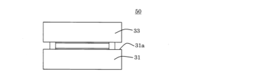
- Test jig 50 is a test jig for conducting a leak test of an annular sealing material that seals a gap between two members.
- the test jig 50 includes a mounting table 31 having a mounting surface 31a on which a sealing material is placed, an upper arrangement member 33 disposed above the sealing material mounted on the mounting table 31, and a mounting table. and a leak detection member 35 located outside the sealing material placed on the 31 .
- the leak detection member 35 contains a gaschromic material that reversibly changes its color or changes its electrical resistance value by an oxidation-reduction reaction.
- the test jig 50 changes the color or electrical resistance value of the portion of the leakage detecting member 35 where leakage from the sealing material is recognized in accordance with leakage from the sealing material, and detects the presence or absence of leakage and the location of the leakage. can be detected.
- Such a sealing material test jig 50 can easily and accurately detect the presence or absence of leakage in the sealing material and its position. Further, the test jig 50 is for placing the sealing material on the mounting table 31 during the seal inspection, so that it is possible to avoid damaging the inspection object during the seal inspection.
- the test jig 50 is attached to the test portion of a test device 200 for testing the sealing performance of the sealing material 15, and then, using a test fluid such as hydrogen, the test fluid is
- a test fluid such as hydrogen
- the test fluid is This is a jig that detects the presence or absence of leaks and the location of leaks based on changes in color, etc.
- the sealing material 15 a test product for testing sealing performance
- the test apparatus 200 has the same configuration as the test apparatus 100 except that the test jig 50 is installed in the test section.
- FIG. 8 is a plan view showing a state after the test jig 50 is attached to the test device 200 and the sealing performance of the sealing material 15 is tested. This is an example showing that a part is discolored and a discolored portion 27 is developed.
- a sealing material is the same as the sealing product described above, but it is a device that prevents fluid from leaking from the inside of the machine to the outside, and specifically includes oil seals, rubber gaskets, O-rings, etc.
- the mounting table 31 has a mounting surface 31a on which the sealing material 15 is mounted. As long as it has the mounting surface 31a in this way, there are no particular restrictions on its material, shape, size, and the like.
- the material of the mounting table 31 is not particularly limited as long as the material does not leak the test fluid when the sealing material is sandwiched.
- Examples of the material of the mounting table 31 include resin, glass, steel materials such as stainless steel, and aluminum.
- FIGS. 5 and 6 show a cubic mounting table 31, and show an example of having a mounting surface 31a on which the sealing material 15 is mounted on the top surface.
- the upper arrangement member 33 is arranged above the sealing material mounted on the mounting table 31 .
- the material, shape, size, etc. of the upper arranged member 33 are not particularly limited and can be determined as appropriate.
- FIG. 5 shows a cubic upper arranged member 33, and a sheet member 37 as a leakage detection member 35 is arranged on the surface on the mounting table 31 side.
- the material of the upper arranged member 33 is not particularly limited as long as it is a material that does not leak the test fluid when the sealing material is clamped, like the mounting table 31 .
- Examples of materials for the upper arranged member 33 include resin, glass, steel materials such as stainless steel, and aluminum.
- the upper arranged member 33 can be made of resin or glass, and in the case of resin, it can be made of a transparent material.
- transparent materials include acrylic resins and polycarbonates.
- the leak detection member 35 is positioned outside the sealing material 15 mounted on the mounting table 31, and contains a gaschromic material that reversibly changes color or changes electrical resistance by an oxidation-reduction reaction. there is The leakage detection member 35 and the sealing material 15 may be arranged so as to be in contact with each other, or may be arranged with a gap therebetween.
- the material of the leak detection member 35 is not particularly limited, but examples include resin and rubber.
- the position of the leak detection member 35 is not particularly limited as long as it is positioned outside the sealing material 15 .
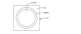
- the leakage detection member 35 may be arranged as a sheet member 37 on the surface of the mounting table 31 or the upper arranged member 33 , or may be arranged as a protrusion 39 on the mounting table 31 . Note that both the sheet member 37 and the protrusion 39 may be used as the leakage detection member 35 . In this way, the presence or absence of leakage and its location can be confirmed more accurately.
- the test jig 50 may further include a sheet-shaped sheet member 37 arranged on at least one of the mounting table 31 side and the upper arranged member 33 side of the sealing material 15.
- a sealing material is arranged so as to be positioned outside the sheet member 37 .
- At least one of the sheet members 37 can constitute at least a part of the leak detection member 35 .
- this sheet member 37 is in the form of a sheet, which includes the case of being in the form of a “thin film”.
- the arrangement of the sheet member 37 is not particularly limited, and the arrangement range (the film formation range in the case of producing a thin film sheet member by film formation) may be the entire surface of the mounting table 31 or the like, or the contact surface of the sealing material. It may be a part such as when (boundary) with.
- the sheet member 37 may be a single-layer sheet, or may be a multi-layered sheet having a thin film in which a gas chromic material is dispersed using a polymeric material as a binder, and a polymeric material film further disposed on this thin film. You can use a sheet.
- the test jig 50 may further include a projecting portion 39 projecting from the mounting surface 31a of the mounting table 31, and when testing the sealing material 15, the inner surface of the projecting portion 39 is brought into contact with the sealing material 15.
- the protrusion 39 can constitute at least a part of the leak detection member 35 .
- the protrusion 39 may have a continuous annular shape as shown in FIG. 6, or may have a discontinuous annular shape.
- the distribution state of the gaschromic material in the protrusion 39 may be limited to the inner surface portion in contact with the sealing member 15, or may be dispersed over the entire surface.
- the projecting portion 39 may be formed integrally with the mounting table 31 or may be formed separately from the mounting table 31 . If it is separate from the mounting table 31 , it is preferably fixed to the mounting table 31 .
- the protruding portion 39 can be made of an elastic material, and the material is not particularly limited, but for example, fluororubber can be mentioned.
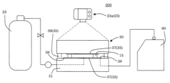
- Test equipment One embodiment of the testing apparatus of the present invention is a testing apparatus 200 for sealants shown in FIG.
- the seal material 15 is set at a predetermined position, and then a test fluid such as hydrogen is supplied to the seal surface (the area inside the seal material) to prevent leakage of the test fluid from the seal surface. It is a testing machine for detection.
- the test apparatus 200 includes the test jig 50 described above, an imaging unit 23 for recording changes in the leak detection member 35 in the test jig 50, a test fluid supply unit 25, and a leak amount measurement unit 60. ing.
- the test jig 50 and the test fluid supply section 25 are connected by piping.
- the test jig 50 functions as a test section.
- the test fluid supply unit 25 is a tank or the like for supplying a test fluid such as hydrogen to the test jig 50 which is the test unit.
- Such a sealing material test apparatus 200 is provided with the above-described test jig 50, so that the presence or absence of leakage in the sealing material 15 and its position can be detected simply and accurately. Since the portion 60 can measure the leakage amount of the leaking fluid, the leakage countermeasure effect is improved.
- the first method is to disassemble the test jig 50 after the test and check it
- the second method is to configure a part of the test jig 50 with a transparent member and check it during the test.
- the leak position can be specified by analyzing the image captured by the imaging unit 23 such as a camera.
- the test apparatus 200 shown in FIG. 7 has at least one (preferably, the upper arranged member 33) of two members (that is, the upper arranged member 33 and the mounting table 31 of the test jig 50) that sandwich the sealing material 15. , a transparent member (for example, acrylic resin, glass, etc.) through which light can pass.
- This test apparatus 200 adopts the second method described above, and detects discoloration of the leaking portion with the camera 23a (photographing unit 23).
- the imaging unit 23 is not particularly limited as long as it can record the presence or absence of leakage in the sealing material 15 and its position, and a predetermined device can be appropriately adopted.
- the leakage amount measuring unit 60 measures the amount of leakage of the leaking fluid, and is a distributed rubber sheet that is a probe arranged between the sealing material 15 to be tested and the protrusion 39 (leak detection member 35). 38.
- Specific examples of the leak rate measurement unit 60 include a pressure gauge, a flow meter, a leak detector, and the like, and the leak rate can be detected by changes in the electrical resistance of the dispersion rubber sheet 38 .
- the above-described test jig 50 alone can only confirm the change in color and cannot grasp the amount of leakage. It becomes possible to distinguish places where minute leaks are likely to occur. Since it is conceivable that the cause of leakage differs depending on the amount of leakage, by using the leakage amount measuring unit 60 and the test jig 50 in combination, countermeasures against leakage can be taken more effectively.
- the leakage detection member of the present invention comprises a tubular elastic portion made of an elastic material containing a gaschromic material whose color reversibly changes or electrical resistance changes due to an oxidation-reduction reaction, and the tubular elastic portion. and at least one pair of electrodes arranged on the outer peripheral surface.
- a leak detection member can easily and accurately detect the presence or absence of leakage of gas or the like from a pipe or the like and the location of the leakage.
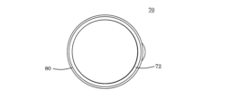
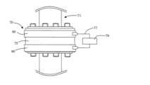
- the leak detection member 70 includes a cylindrical elastic portion 72 made of an elastic material containing a gaschromic material whose color reversibly changes or whose electric resistance value changes due to an oxidation-reduction reaction, and the cylindrical elastic portion 72. and a pair of electrodes 80 respectively arranged on the outer peripheral surface of the one end surface 73 side and the other end surface 75 side.
- Such a leak detection member 70 can easily and accurately detect the presence or absence of leakage of gas or the like from a pipe or the like and the location of the leakage.
- the leak detection member 70 is attached to a joint (fastening portion) of the hydrogen pipe 71 or the like, and leaks from the joint or the like are detected by changes in color or electrical resistance. It is an instrument that detects by Furthermore, as shown in FIG. 11, by attaching a conducting wire 77 to the leak detection member 70 and connecting it to a measuring device 79 such as a voltmeter or an ammeter, when a leak occurs, not only the color change but also the electrical resistance Leakage can be detected by checking the change in
- the tubular elastic portion 72 is tubular and made of an elastic material containing a gaschromic material whose color is reversibly changed or whose electric resistance value is changed by an oxidation-reduction reaction.
- the size and opening shape of the tubular elastic portion 72 are not particularly limited as long as they are tubular, and can be appropriately determined in accordance with the shape and size of the piping to which the leak detection member 70 is attached.
- the shape of the cylindrical elastic portion 72 can be cylindrical.
- the cylindrical elastic portion 72 may have a slit or a notch formed in its central axis direction. This is because the formation of the slits and notches facilitates work such as piping. In addition, even when a part is missing due to the formation of a notch, it corresponds to the "cylindrical shape".
- the material of the elastic material of the tubular elastic portion 72 is not particularly limited. (NBR) and the like.
- a pair of electrodes The pair of electrodes 80 are arranged on the outer peripheral surface of the cylindrical elastic portion 72 on one end surface 73 side and the other end surface 75 side, respectively.
- Electrodes can be adopted for the pair of electrodes 80, and the positions of the electrodes can be determined as appropriate without any particular limitations.
- each electrode may have a ring shape arranged along the outer peripheral surface of the cylindrical elastic portion 72, and a part of the ring structure may be missing.
- a measuring instrument 79 such as an ammeter can be connected to each of the electrodes 80 as shown in FIG. Leakage can be confirmed (detected).
- FIG. 12 shows the state of use of the leak detection member 70, and the leak detection member 70 is arranged at a plurality of fastening portions present in the pipe. Then, an electric signal is transmitted wirelessly or the like in each leak detection member 70 and observed.
- the leak detection member 90 arranged at the portion where gas leakage occurs the color of the tubular elastic portion 72 changes, and the current resistance value of the tubular elastic portion 72 also changes.
- leak detection members 70 may be attached to joints of pipes through which hydrogen flows, and electrical signals sent from these may be monitored for 24 hours. By monitoring the electric signal in this way, even if a leak occurs, it is possible to quickly identify the joint where the leak has occurred from among many joints.
- FIG. 13 shows a leak detection member 170 of another embodiment of the leak detection member of the present invention.
- the leak detection member 170 includes a tubular elastic portion 72 and a plurality of pairs of electrodes 80 arranged on the surface of the tubular elastic portion 72 .
- the multiple pairs of electrodes 80 are arranged side by side in the direction in which the cylindrical elastic portion 72 extends (the central axis direction).
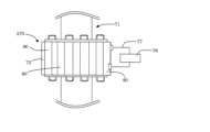
- FIG. 14 shows a leak detection member 270 of another embodiment of the leak detection member of the present invention.
- the leak detection member 270 includes a tubular elastic portion 72 and a plurality of pairs of electrodes 80 arranged on the surface of the tubular elastic portion 72.
- the plural pairs of electrodes 80 extend from the tubular elastic portion 72. It is arranged so as to extend along the direction (central axis direction). By providing a plurality of pairs of electrodes 80 in this way, it is possible to detect leak positions in the circumferential direction.
- the rubber product of the present invention can be used as a sealing material in joints (fastened parts) of pipes and the like.
- INDUSTRIAL APPLICABILITY The test jig and testing apparatus for sealing materials of the present invention can be used as a jig or device for testing the presence or absence of leakage in sealing materials at joints of pipes and the like.
- INDUSTRIAL APPLICABILITY The leak detection member of the present invention can be used to detect the presence or absence of leaks in joints of pipes and the like.
Abstract
[Problem] To provide a rubber product wherein the existence and location of a leak can be simply and accurately detected. [Solution] A rubber product including a gasochromic material in which the color reversibly changes or the electrical resistance value changes due to a redox reaction. A rubber product (seal product 10) that is a seal material for sealing a gap between two members, and includes a gasochromic material in which the color reversibly changes or the electrical resistance value changes due to a redox reaction, wherein the rubber product is ring-shaped.
Description
本発明は、ゴム製品、シール材用の試験治具及び試験装置並びに漏れ検知部材に関する。更に詳しくは、配管等をシールするためのシール製品などのゴム製品、シール材用の試験治具及び試験装置並びに漏れ検知部材に関する。
The present invention relates to a rubber product, a test jig and testing device for sealing materials, and a leak detection member. More particularly, the present invention relates to rubber products such as seal products for sealing pipes and the like, test jigs and test devices for seal materials, and leak detection members.
従来、ゴムを主原料とするゴム製品は、多くの分野で使用されており、例えば、パッキンやガスケットのようなシール材などは、自動車や電化製品などに多数用いられている。より具体的には、例えば燃料電池におけるセルアセンブリ間は、ガスケット(ゴム)で封止されている(例えば、特許文献1参照)。
Conventionally, rubber products that use rubber as the main raw material have been used in many fields. For example, sealing materials such as packings and gaskets are widely used in automobiles and electrical appliances. More specifically, for example, between cell assemblies in a fuel cell is sealed with a gasket (rubber) (see Patent Document 1, for example).
このガスケットは、燃料電池における水素漏れを防ぐものであり、水素漏れは様々な問題を生じる懸念がある。そのため、燃料電池に組付ける前における検査(シール検査)が特に重要であり、シール検査では漏洩の有無や漏洩位置を確認することが求められる。
This gasket prevents hydrogen leakage from the fuel cell, and there are concerns that hydrogen leakage may cause various problems. Therefore, the inspection (seal inspection) before assembly to the fuel cell is particularly important, and it is required to check the presence or absence of leakage and the location of leakage in the seal inspection.
このようなシール検査に際して、クロミック材を用いた水素漏れ検知の方法が提案されている(例えば、特許文献2参照)。
A hydrogen leak detection method using a chromic material has been proposed for such seal inspections (see, for example, Patent Document 2).
しかしながら、特許文献2に記載のシートは、シール検査に際して、検査対象であるガスケット等に貼り付ける作業が必要になる。また、検査終了後には、検査対象であるガスケットから上記シートを剥がすことが必要になり、当該シートを剥がす際に検査対象に傷が付くことなどの懸念があった。
However, the sheet described in Patent Document 2 requires work to be attached to the gasket or the like to be inspected when performing a seal inspection. Moreover, after the inspection is finished, it is necessary to peel off the sheet from the gasket to be inspected, and there is a concern that the inspection object may be damaged when the sheet is peeled off.
更に、特許文献2に記載のシートを検査対象に貼り付けた際に、シートと検査対象との間に僅かな隙間が生じる場合があり、この隙間があると、隙間周辺部分が広く変色してしまうことがある。そのため、漏洩は認められるものの、その正確な場所を検知できないという懸念があった。このように特許文献2に記載のシートであっても、未だ改良の余地があった。
Furthermore, when the sheet described in Patent Document 2 is attached to an object to be inspected, a slight gap may occur between the sheet and the object to be inspected. I can put it away. Therefore, there was a concern that although the leak was recognized, its exact location could not be detected. Thus, even the sheet described in Patent Document 2 still has room for improvement.
本発明は、このような従来技術に鑑みてなされたものであり、その課題とするところは、シール検査の際に検査対象を傷付けてしまうことを回避することができ、更に、漏洩の有無及びその位置について簡便に且つ精度良く検知することができるゴム製品、シール材用の試験治具及び試験装置並びに漏れ検知部材を開発することにある。
The present invention has been made in view of such prior art, and its object is to avoid damaging the inspection object during seal inspection, and furthermore, to check the presence or absence of leakage. An object of the present invention is to develop a test jig and testing device for rubber products and seal materials, and a leak detection member, which can detect the position of the leak simply and accurately.
本発明によれば、以下に示す、ゴム製品、シール材用の試験治具及び試験装置並びに漏れ検知部材が提供される。
According to the present invention, the following test jigs and testing devices for rubber products and sealing materials, and leak detection members are provided.
[1] 酸化還元反応により色が可逆的に変化または電気抵抗値が変化するガスクロミック材料を含有する、ゴム製品。
[1] A rubber product that contains a gaschromic material that reversibly changes color or changes electrical resistance due to an oxidation-reduction reaction.
[2] 2つの部材の間の隙間を密封するシール材であって、
酸化還元反応により色が可逆的に変化または電気抵抗値が変化するガスクロミック材料を含有し、環状である、前記[1]に記載のゴム製品。 [2] A sealing material for sealing a gap between two members,
The rubber product according to the above [1], which contains a gaschromic material that reversibly changes color or changes electric resistance by an oxidation-reduction reaction, and is cyclic.
[3] 透明なものである、前記[1]または[2]に記載のゴム製品。
[3] The rubber product according to [1] or [2] above, which is transparent.
[4] 水素ガスと接するシール材である、前記[1]~[3]のいずれかに記載のゴム製品。
[4] The rubber product according to any one of the above [1] to [3], which is a sealing material in contact with hydrogen gas.
[5] 2つの部材の間の隙間を密封する環状のシール材の漏洩試験を行うための試験治具であり、
前記シール材を載置する載置面を有する載置台と、
前記載置台に載置された前記シール材の上方に配置される上方配置部材と、
前記載置台に載置された前記シール材の外側に位置する漏洩検知部材と、を備え、
前記漏洩検知部材は、酸化還元反応によって色が可逆的に変化または電気抵抗値が変化するガスクロミック材料を含有しており、
前記シール材からの漏洩に伴い、前記漏洩検知部材の、前記シール材からの漏洩が認められる部分における色が変化する、シール材用の試験治具。 [5] A test jig for conducting a leak test of an annular sealing material that seals a gap between two members,
a mounting table having a mounting surface on which the sealing material is mounted;
an upper arranged member arranged above the sealing material mounted on the mounting table;
a leakage detection member positioned outside the sealing material mounted on the mounting table;
The leakage detection member contains a gaschromic material that reversibly changes color or changes electric resistance by oxidation-reduction reaction,
A test jig for a sealing material, wherein a color of a portion of the leakage detection member where leakage from the sealing material is recognized changes with leakage from the sealing material.
[6] 前記シール材の前記載置台側及び前記上方配置部材側の少なくとも一方に配置されるシート状のシート部材を備え、
前記シート部材の少なくとも一方が、前記漏洩検知部材の少なくとも一部を構成する、前記[5]に記載の試験治具。 [6] A sheet-shaped sheet member arranged on at least one of the mounting table side and the upper arranged member side of the sealing material,
The test jig according to [5], wherein at least one of the sheet members constitutes at least part of the leakage detection member.
[7] 前記載置台の前記載置面から突出した突起部を備え、
前記突起部が、前記漏洩検知部材の少なくとも一部を構成する、前記[5]または[6]に記載の試験治具。 [7] A protrusion projecting from the mounting surface of the mounting table,
The test jig according to [5] or [6], wherein the protrusion constitutes at least part of the leakage detection member.
前記突起部が、前記漏洩検知部材の少なくとも一部を構成する、前記[5]または[6]に記載の試験治具。 [7] A protrusion projecting from the mounting surface of the mounting table,
The test jig according to [5] or [6], wherein the protrusion constitutes at least part of the leakage detection member.
[8] 前記上方配置部材が、透明の部材からなるものである、前記[5]~[7]のいずれかに記載の試験治具。
[8] The test jig according to any one of [5] to [7], wherein the upper member is made of a transparent member.
[9] 前記[4]~[8]のいずれかに記載の試験治具と、
前記試験治具における前記漏洩検知部材の変化を記録する撮影部と、を備える、シール材用の試験装置。 [9] The test jig according to any one of [4] to [8];
and a photographing unit for recording changes in the leak detection member in the test jig.
前記試験治具における前記漏洩検知部材の変化を記録する撮影部と、を備える、シール材用の試験装置。 [9] The test jig according to any one of [4] to [8];
and a photographing unit for recording changes in the leak detection member in the test jig.
[10] 酸化還元反応によって色が可逆的に変化または電気抵抗値が変化するガスクロミック材料を含有する弾性材からなる筒状の筒状弾性部と、
前記筒状弾性部の外周面に配置された少なくとも一対の電極と、を備える、漏れ検知部材。 [10] a cylindrical elastic portion made of an elastic material containing a gaschromic material that reversibly changes color or changes electrical resistance by an oxidation-reduction reaction;
and at least a pair of electrodes arranged on the outer peripheral surface of the tubular elastic portion.
本発明のゴム製品は、漏洩の有無及びその位置について簡便に且つ精度良く検知することができるという効果を奏する。なお、このゴム製品は、シール材(シール製品)として用いることにより、シール検査の際に検査対象を傷付けてしまうことを回避することができ、更に、漏洩の有無及びその位置について簡便に且つ精度良く検知することができるという効果を奏する。
The rubber product of the present invention has the effect of being able to easily and accurately detect the presence or absence of leakage and its location. In addition, by using this rubber product as a sealing material (sealing product), it is possible to avoid damaging the inspection object during the seal inspection, and furthermore, it is possible to easily and accurately check the presence or absence of leakage and its position. It is effective in being able to detect well.
本発明のシール材用の試験治具は、シール材における漏洩の有無及びその位置について簡便に且つ精度良く検知することができるという効果を奏する。
The test jig for sealing materials of the present invention has the effect of being able to easily and accurately detect the presence or absence of leakage in the sealing material and its position.
本発明のシール材用の試験装置は、シール材における漏洩の有無及びその位置について簡便に且つ精度良く検知することができるという効果を奏する。
The sealing material testing device of the present invention has the effect of being able to detect the presence or absence of leakage in the sealing material and its position simply and accurately.
本発明の漏れ検知部材は、配管等からのガス等の漏洩の有無及び漏洩の位置について簡便に且つ精度良く検知することができるという効果を奏する。
The leak detection member of the present invention has the effect of being able to easily and accurately detect the presence or absence of leakage of gas, etc. from a pipe or the like, and the location of the leakage.
以下、本発明の実施形態を、図面を参照しながら説明する。なお、本発明は以下の実施形態に限定されるものではなく、本発明の趣旨を逸脱しない範囲で、当業者の通常の知識に基づいて、適宜設計の変更、改良等が加えられることが理解されるべきである。
Hereinafter, embodiments of the present invention will be described with reference to the drawings. It should be noted that the present invention is not limited to the following embodiments, and it is understood that design changes, improvements, etc., can be made as appropriate based on the ordinary knowledge of those skilled in the art without departing from the scope of the present invention. It should be.
(1)ゴム製品:
本発明のゴム製品の一の実施形態は、酸化還元反応により色が可逆的に変化または電気抵抗値が変化するガスクロミック材料を含有するものである。このゴム製品は、漏洩の有無及び漏洩の位置について簡便に且つ精度良く検知することができる。 (1) Rubber products:
One embodiment of the rubber product of the present invention contains a gaschromic material that reversibly changes color or changes electrical resistance by oxidation-reduction reaction. With this rubber product, the presence or absence of leakage and the location of leakage can be easily and accurately detected.
ガスクロミック材料は、酸化還元反応によって、色が可逆的に変化するか、或いは、電気抵抗値が変化する材料である。このようなガスクロミック材料としては、後述するように、例えば、酸化タングステン、酸化バナジウム、酸化ニオブ、酸化タンタル、酸化ジルコニウム、及び酸化クロムなどの遷移金属酸化物を挙げることができる。なお、反応を促進するために、白金やクロムなどの触媒を更に担持させることが好ましい。例えば、酸化タングステン及び白金を含むものであることがより好ましい。
A gaschromic material is a material whose color changes reversibly or whose electrical resistance value changes due to an oxidation-reduction reaction. Examples of such gaschromic materials include transition metal oxides such as tungsten oxide, vanadium oxide, niobium oxide, tantalum oxide, zirconium oxide, and chromium oxide, as described later. In addition, in order to promote the reaction, it is preferable to further support a catalyst such as platinum or chromium. For example, it is more preferable to contain tungsten oxide and platinum.
なお、本発明のゴム製品においては、酸化還元反応により光の透過率が変化する(即ち、特定の波長帯の透過率が大きく変化する)ことで色が変化して見えることになる。
In addition, in the rubber product of the present invention, the light transmittance changes due to the oxidation-reduction reaction (that is, the transmittance in a specific wavelength band changes greatly), so that the color appears to change.
このゴム製品の材料となるゴムは、従来公知のものを適宜採用することができ、このゴム製品の用途は特に制限はなく、シール材のようなシール製品などに用いることができる。
Conventionally known rubbers can be suitably used as the material of this rubber product, and the use of this rubber product is not particularly limited, and it can be used for sealing products such as sealing materials.
本発明のゴム製品は、例えば以下のように製造することができる。まず、従来公知の方法(例えば特開2017-181996号公報等参照)により、白金(Pt)と酸化タングステン(WO3)を含む固形物を合成する。次に、合成した固形物を粉砕する。ここで、固形物の粉砕手段としては、例えば、ビーズミル、ジェットミル、乳鉢などが挙げられる。なお、ゴム製品中でのPt、WO3の分散性を向上させる場合には、任意の分散剤で表面処理を行っても良い。
The rubber product of the present invention can be produced, for example, as follows. First, a solid containing platinum (Pt) and tungsten oxide (WO 3 ) is synthesized by a conventionally known method (see, for example, JP-A-2017-181996). Next, the synthesized solid matter is pulverized. Examples of means for pulverizing solids include bead mills, jet mills, and mortars. In order to improve the dispersibility of Pt and WO3 in rubber products, surface treatment may be performed with an arbitrary dispersant.
次に、粉砕した固形物(「Pt/WO3」と記す場合がある)をその他の成分とともに原料ゴムと混合する。なお、混合のタイミングは、混錬時や加硫剤を投入する促入れ時などのようにゴムを加硫する前の段階であれば特に制限はない。混合用の装置としては、特に制限はなく、ニーダーやロールなどのゴムの混錬に使用される一般的な装置を採用することができる。また、原料ゴムとして液状ゴムを用いる場合は、装置を用いずに手動で混ぜても良い。そして、その後、Pt/WO3を混合したゴム生地を任意の形状に成形し加硫を行うことにより、ゴム製品を製造することができる。
Next, the pulverized solid (sometimes referred to as “Pt/WO 3 ”) is mixed with raw rubber together with other components. The timing of mixing is not particularly limited as long as it is at a stage before vulcanization of rubber, such as during kneading or during introduction of a vulcanizing agent. The device for mixing is not particularly limited, and a general device used for kneading rubber such as a kneader and rolls can be employed. Moreover, when liquid rubber is used as the raw material rubber, it may be mixed manually without using a device. After that, the rubber material mixed with Pt/WO 3 is formed into an arbitrary shape and vulcanized to produce a rubber product.
(2)シール製品:
本発明のゴム製品の一の実施形態は、図1、図2に示すシール製品10である。このシール製品10は、2つの部材(例えば、配管同士、セパレータ同士)の間の隙間を密封するシール材であって、酸化還元反応によって色が可逆的に変化または電気抵抗値が変化するガスクロミック材料を含有し、環状のものである。 (2) Seal products:
One embodiment of the rubber product of the present invention is theseal product 10 shown in FIGS. This sealing product 10 is a sealing material for sealing a gap between two members (for example, pipes or separators), and is a gaschromic material that reversibly changes color or changes electrical resistance by oxidation-reduction reaction. It contains material and is annular.
本発明のゴム製品の一の実施形態は、図1、図2に示すシール製品10である。このシール製品10は、2つの部材(例えば、配管同士、セパレータ同士)の間の隙間を密封するシール材であって、酸化還元反応によって色が可逆的に変化または電気抵抗値が変化するガスクロミック材料を含有し、環状のものである。 (2) Seal products:
One embodiment of the rubber product of the present invention is the
このようなシール製品10は、漏洩の有無及びその位置について簡便に且つ精度良く検知することができる。なお、シール製品10とは、機械内部から外部へと流体の漏れを防ぐ装置のことであり、具体的には、オイルシール、ゴムガスケット、Оリング等が該当する。
Such a sealing product 10 can easily and accurately detect the presence or absence of leakage and its position. The seal product 10 is a device that prevents fluid from leaking from the inside of the machine to the outside, and specifically includes oil seals, rubber gaskets, O-rings, and the like.
ここで、Oリング及びガスケットなどのシール製品は、機械同士の接合箇所に取り付けられ、機械内部の液体や気体が外部に漏れることを防ぐ装置である。しかし、外乱や突発的な欠陥などの要因で気密性が不足して漏れが発生することも懸念される。
Here, sealing products such as O-rings and gaskets are devices that are attached to the joints between machines and prevent liquids and gases inside the machines from leaking to the outside. However, there is concern that leaks may occur due to insufficient airtightness due to factors such as disturbances and sudden defects.
そして、漏れが発生した場合、原因を究明して対策を行うことになるが、そのためには漏れ位置を特定する必要がある。しかし、シール媒体が無色気体(例えば、水素等)の場合、漏れ位置を正確に目視で特定することは容易ではない傾向がある。
Then, if a leak occurs, the cause will be investigated and countermeasures will be taken, but in order to do so, it is necessary to identify the location of the leak. However, when the sealing medium is a colorless gas (such as hydrogen), it tends to be difficult to accurately visually identify the leak location.
そこで、一般的には、印加した圧力値の変動を観察する方法や、印加する気体の流量を測定する方法などが採用される。しかし、これらの手法では、漏れの有無を判別するに留まり、漏れ位置の特定は十分に行えない傾向がある。
Therefore, in general, a method of observing fluctuations in the applied pressure value, a method of measuring the flow rate of the applied gas, and the like are adopted. However, these methods only determine the presence or absence of leakage, and tend to be unable to sufficiently specify the location of the leakage.
このようなことから、漏れ位置の特定手法として、圧力測定区域を細かく分割し個々の圧力変動から漏れ位置を特定する手法がある。しかし、コンタクトラインのどの部分から漏れているかは判別できない。そこで、より細かく漏れ位置を検査する手法として、Heなどの気体を印加し、リークディテクターなどの検出器に接続したプローブを試験体の近傍で走査することで漏れ位置を特定する方法もある。しかし、この手法であっても、プローブに届く前にHeが拡散してしまうため、シール製品のように漏れ量が小さい場合は測定が困難となる傾向がある。
Therefore, as a method of identifying the leak location, there is a method of finely dividing the pressure measurement area and identifying the leak location from the individual pressure fluctuations. However, it cannot be determined from which part of the contact line the leak is coming from. Therefore, as a method for inspecting the leak position more precisely, there is also a method of applying gas such as He and scanning the vicinity of the test object with a probe connected to a detector such as a leak detector to specify the leak position. However, even with this method, He diffuses before it reaches the probe, so it tends to be difficult to measure when the amount of leakage is small, such as in sealed products.
次に、漏れ位置を可視化する手法として、検査液をシール箇所に塗布してアクリル板などの透明部材で締め付け、圧力印加時に発生する泡を観察することで漏れ箇所を特定する発泡法がある。しかし、この手法でも、漏れ量が小さい場合には、泡の観察が困難であったり、検査液自体がシールの助剤となり漏れを止めてしまうという懸念がある。
Next, as a method for visualizing the leak location, there is a foaming method that identifies the leak location by applying a test liquid to the seal location, tightening it with a transparent member such as an acrylic plate, and observing the bubbles generated when pressure is applied. However, even with this method, if the amount of leakage is small, there is a concern that bubbles may be difficult to observe, or that the test liquid itself may serve as an aid for sealing to stop leakage.
また、シール媒体であるガスの中には、H2やHeなどのように物体の透過性が高いものも含まれる。このうちH2は、O2と反応することによる爆発のリスクが広く知られている。そのため、外部へのH2の漏れを完全に無くすことは困難でありながらも、安全性を担保する観点から、最小限の漏れ量とすることが求められている。特に、締結部の隙間を埋めるために使用されているシール製品は、比較的低密度の弾性体で形成されていることが多く、そのため、透過漏れが生じる懸念もある。
Gases that are sealing media include gases such as H 2 and He that are highly permeable to matter. Of these, H 2 is widely known to have an explosion risk due to its reaction with O 2 . Therefore, although it is difficult to completely eliminate the leakage of H2 to the outside, it is required to minimize the amount of leakage from the viewpoint of ensuring safety. In particular, sealing products used to fill gaps between fastening parts are often formed of elastic bodies with relatively low density, and therefore there is a concern that permeation leakage may occur.
本発明では、ガスクロミック材料を樹脂等の高分子材料に混合することによって、シール製品自体をセンサとして活用できることを見出したものである。
In the present invention, it was discovered that the sealing product itself can be used as a sensor by mixing a gaschromic material with a polymeric material such as resin.
このようにシール製品自体をセンサとすると、漏れ発生部位の正確な特定が容易になることに加え、他のセンサ装置を設置する手間を省略することができる。つまり、本発明のゴム製品(具体的にはシール製品)を用いると、周辺部材をそのまま使用して、漏れを検知することが可能となる。
Using the seal product itself as a sensor in this way not only facilitates accurate identification of the leak occurrence site, but also saves the trouble of installing another sensor device. In other words, by using the rubber product (specifically, the seal product) of the present invention, leakage can be detected using the peripheral member as it is.
また、ガスクロミック材料は、可逆性を有することから、同一製品であれば繰り返し使用できるので経済性に優れている。なお、可逆反応の時間は、ガス透過率の低い高分子材料を使用したり、高分子材料を重ねて2層成形することによって調整することができる。使用する高分子材料としては、仕様や漏れの観察の環境に適したものを適宜選択可能である。
In addition, since gaschromic materials are reversible, the same product can be used repeatedly, making it economical. The time for the reversible reaction can be adjusted by using a polymeric material with a low gas permeability or by stacking polymeric materials to form two layers. As the polymer material to be used, a material suitable for the specifications and the environment for observing leakage can be appropriately selected.
また、本発明では、微小な漏れ(例えば0.1cc/分を下回るような非常に小さな漏れ)も検出可能となる。カメラで取得した画像の画像処理や電気信号の取得などのように検知方法を選択することができ、ガスクロミズム発色性能(色調や維持時間)及び抵抗値変化性能を使用環境で制御できるためである。
Also, in the present invention, minute leaks (for example, very small leaks of less than 0.1 cc/min) can be detected. This is because the detection method can be selected, such as image processing of images acquired by a camera or acquisition of electrical signals, and the gas chromism color development performance (color tone and maintenance time) and resistance value change performance can be controlled in the usage environment. .
更に、本実施形態のシール製品は、漏れ位置を特定するだけでなく、気体の流れを可視化することへの応用も可能である。例えば、燃料電池用セルの発電面を流れる水素の流量のムラを可視化することにも応用できる。即ち、シール製品の内部に水素の流れがあり、その水素の流量が大きい領域(多流量領域)に近い部分ほど、シール製品の内面部分が強く変色(濃く変色)し、上記多流量領域から遠い部分ほど、シール製品の内面部分は薄く変色する。そこで、シール製品の内面部分の変色の程度を確認すると、水素流量の分布が分かるようになる。
Furthermore, the seal product of this embodiment can be applied not only to identify the leak position, but also to visualize the gas flow. For example, it can be applied to visualize unevenness in the flow rate of hydrogen flowing on the power generation surface of a fuel cell. That is, there is a flow of hydrogen inside the seal product, and the inner surface portion of the seal product is strongly discolored (deeply discolored) in a portion closer to a region where the flow rate of hydrogen is large (high flow rate region), and is farther from the high flow rate region. The inner surface portion of the seal product is lightly discolored. Therefore, by checking the degree of discoloration of the inner surface of the seal product, the hydrogen flow rate distribution can be known.
このようなシール製品(即ち、ゴム製品)は、水素ガスと接するシール材として用いることができ、例えば、燃料電池用セルのシール材、水素を燃焼(爆発)させるエンジンや水素タンク・配管、工場内での水素配管用のシールまたはガスケットに適用することができる。
Such sealing products (that is, rubber products) can be used as sealing materials in contact with hydrogen gas. It can be applied to seals or gaskets for hydrogen piping in
なお、本発明のようにガスクロミック材料を混合した弾性体をシール製品(燃料電池用セルに用い、セル内の水素と接するシール材)に適用すると、ガスクロミック材料の酸化還元反応によってゴム(シール製品)中で水素を水に変換することができると考えられる。つまり、水素が外部に漏れる前に水に変換してしまうことが考えられるので、水素漏れを防止でき、水素漏れによる事故のリスクを低減することができると考えられる。ここで、シール製品の低圧側には、シール製品の内部に侵入した酸素が僅かながら存在しており、漏れる直前の水素の一部は、この酸素との還元反応によって水に変換されることになると考えられる。
It should be noted that if an elastic material mixed with a gaschromic material is applied to a sealing product (a sealing material that is used in a fuel cell and is in contact with hydrogen in the cell) as in the present invention, the oxidation-reduction reaction of the gaschromic material causes a rubber (sealing material). It is believed that hydrogen can be converted to water in the product). In other words, it is conceivable that hydrogen will be converted to water before it leaks to the outside, so hydrogen leaks can be prevented and the risk of accidents due to hydrogen leaks can be reduced. Here, on the low-pressure side of the sealing product, there is a small amount of oxygen that has entered the interior of the sealing product, and part of the hydrogen immediately before leaking is converted into water by a reduction reaction with this oxygen. It is considered to be.
更に、シール製品の製造段階においては、シール製品からの漏れの有無を確認する工程があるが、この確認工程においては、漏れの有無が正確に検知できることが望まれる。
Furthermore, at the stage of manufacturing seal products, there is a process to check for leaks from the seal products, and it is desirable to be able to accurately detect the presence or absence of leaks in this confirmation process.
本実施形態のシール製品は、シール製品そのもの自体にガスクロミック材料が含有され、当該シール製品自体が直接に漏れに対応して変化するため、漏れの位置をより精度よく且つ簡便に検知することができる。また、水素ガスが使用される場合には水素漏れを防止でき、水素漏れによる事故のリスクを低減することができる。ここで、水素検知用シート(例えば、特許文献2参照)を別途用いる場合には、漏れ検知対象物と水素検知用シートとに隙間が生じることがあり、その場合には漏れている箇所を正確に検知できない懸念がある。つまり、隙間が生じている部分が全体に広く変色してしまうため、漏れの存在は認識できるものの、漏れの場所までは正確に確認することが十分でない傾向がある。これに対して、本実施形態のシール製品は、漏れが生じることで、上記の通り漏れ検知対象物(シール製品自体)が変色するため、漏れ位置を正確に把握することができる。更に、上記水素検知用シートのように漏れ検知対象物に別部材を採用し、この別部材を漏れ検知対象物に直接貼り付けるということが無いため、シール検査の際に検査対象(即ち、漏れ検知対象物)を傷付けてしまうことを回避することができる。
In the seal product of the present embodiment, the seal product itself contains a gaschromic material, and the seal product itself changes in response to leakage directly, so the position of the leak can be detected more accurately and easily. can. Moreover, when hydrogen gas is used, hydrogen leakage can be prevented, and the risk of accidents due to hydrogen leakage can be reduced. Here, when a hydrogen detection sheet (see, for example, Patent Document 2) is separately used, a gap may occur between the leak detection target and the hydrogen detection sheet. There is a concern that it is not possible to detect In other words, since the portion where the gap is generated is discolored widely as a whole, the presence of the leak can be recognized, but there is a tendency that it is not sufficient to accurately confirm the location of the leak. On the other hand, in the seal product of the present embodiment, when a leak occurs, the leak detection target (the seal product itself) changes color as described above, so the leak position can be accurately grasped. Furthermore, unlike the above-mentioned hydrogen detection sheet, a separate member is not used for the leak detection target and this separate member is not directly attached to the leak detection target. (detection object) can be avoided from being damaged.
本実施形態のシール製品は、弾性を有しておりその材質は特に制限はないが、例えば、ビニルメチルシリコーンゴム(VMQ)、フッ化ビニリデン系ゴム(FKM)、エチレンプロピレンジエンゴム(EPDM)、アクリロニトリル・ブタジエンゴム(NBR)などを挙げることができる。本実施形態のシール製品は、透明なものとすることができる。透明なものであると、シール製品内部の亀裂等による漏れをその変色によって外部から確実に確認できる。なお、シール製品内部を視認することができる限り有色または無色とすることができるが、無色であることがよい。本願明細書において「透明」は、完全に透明である場合以外に、光を透過できる程度に透明である場合(半透明)を含む概念である。
The sealing product of the present embodiment has elasticity, and the material thereof is not particularly limited. Examples include acrylonitrile-butadiene rubber (NBR). The seal product of this embodiment can be transparent. If it is transparent, leakage due to cracks or the like inside the seal product can be reliably confirmed from the outside by its discoloration. As long as the inside of the seal product can be visually recognized, it can be colored or colorless, but it is preferably colorless. In the present specification, "transparent" is a concept that includes not only completely transparent but also transparent enough to transmit light (translucent).
ガスクロミック材料は、酸化還元反応によって、色が可逆的に変化するか、或いは、電気抵抗値が変化する材料である。このようなガスクロミック材料としては、例えば、酸化タングステン、酸化バナジウム、酸化ニオブ、酸化タンタル、酸化ジルコニウム、及び酸化クロムなどの遷移金属酸化物を挙げることができる。なお、反応を促進するために、白金やクロムなどの触媒を更に担持させることが好ましい。例えば、酸化タングステン及び白金を含むものであることがより好ましい。
A gaschromic material is a material whose color changes reversibly or whose electrical resistance value changes due to an oxidation-reduction reaction. Such gaschromic materials include, for example, transition metal oxides such as tungsten oxide, vanadium oxide, niobium oxide, tantalum oxide, zirconium oxide, and chromium oxide. In addition, in order to promote the reaction, it is preferable to further support a catalyst such as platinum or chromium. For example, it is more preferable to contain tungsten oxide and platinum.
なお、ガスクロミック材料の反応は、可逆的な酸化還元反応であり、水素濃度が高いほど、発色しやすく・抵抗値が低くなるなど変化性能が高くなる。また、酸素濃度が高いほど、発色・抵抗値の変化性能は低くなる。また、温度が高くなるほど、反応が活性化するため、発色・抵抗値の応答性が早くなる。更に、ガスクロミック材料の高分子材料への配合量を増やすことでも、変化性能は高くなる。
The reaction of the gaschromic material is a reversible oxidation-reduction reaction, and the higher the hydrogen concentration, the higher the change performance, such as the easier it is to develop color and the lower the resistance value. In addition, the higher the oxygen concentration, the lower the ability to change color development and resistance value. In addition, the higher the temperature, the more activated the reaction, and the quicker the responsiveness of color development and resistance value. Furthermore, the changing performance can be enhanced by increasing the blending amount of the gaschromic material in the polymeric material.
シール製品10は、その使用条件について特に制限はないが、例えば-60℃~230℃の温度環境で使用され、シール製品10は、このような温度環境において、漏洩の有無及びその位置について簡便に且つ精度良く検知することができる。
The sealing product 10 is not particularly limited as to its usage conditions, but is used in a temperature environment of, for example, -60°C to 230°C. And it can be detected with high accuracy.
漏れを検知する対象である流体としては、特に制限はなく、大気以外の気体を挙げることができ、具体的には、水素などを挙げることができる。例えば、固体高分子型燃料電池の燃料ガスとして水素が使用されており、この水素は電池内にシール製品を用いて密封されている。このような水素は、電池が衝撃や振動等を受けた際に極わずかに漏れてしまう懸念もある。そこで、本実施形態のシール製品を用いることで、漏れの有無や位置を確実かつ容易に検知することができる。
There are no particular restrictions on the fluid to be detected for leaks, and gases other than the atmosphere can be mentioned, specifically hydrogen and the like. For example, hydrogen is used as a fuel gas for polymer electrolyte fuel cells, and this hydrogen is sealed inside the cell using a sealing product. There is a concern that such hydrogen may leak very slightly when the battery is subjected to shock, vibration, or the like. Therefore, by using the sealing product of the present embodiment, the presence or absence and location of leakage can be reliably and easily detected.
シール製品10は、図3に示すように、試験装置100の試験部21に取り付け、漏れの有無及びその位置を確認する試験を行うことができる。試験装置100は、試験部21と、この試験部21に取り付けたシール製品10の変化を記録する撮影部23と、水素などの試験流体を試験部21に供給するための試験流体供給部25と、を備えている。なお、試験部21のうちシール製品10を上方から押さえる部材(上方部材22)は、透明な部材を有し、試験中におけるシール製品10の変化が観察できるようになっている。
As shown in FIG. 3, the seal product 10 can be attached to the test section 21 of the test device 100 and tested to confirm the presence or absence of leakage and its location. The test apparatus 100 includes a test section 21, an imaging section 23 for recording changes in the seal product 10 attached to the test section 21, and a test fluid supply section 25 for supplying a test fluid such as hydrogen to the test section 21. , is equipped with The member (upper member 22) that presses the seal product 10 from above in the test section 21 has a transparent member so that changes in the seal product 10 can be observed during the test.
この試験装置100を用いてシール製品10における漏れの有無を試験することができ、シール製品10に漏れがある場合、図4に示すように、シール製品10の幅方向の全体に亘って変色部27が確認される。このように漏れの有無及びその位置を簡単に検知することができる。
This testing apparatus 100 can be used to test the presence or absence of leakage in the seal product 10. If there is leakage in the seal product 10, as shown in FIG. 27 is confirmed. In this way, the presence or absence of a leak and its location can be easily detected.
シール製品10は、配管等の締結部に配置した後、経年劣化等により使用中に漏れが発生したことや、漏れの発生位置を容易に確認することができる。
After placing the seal product 10 on a joint such as a pipe, it is possible to easily check whether a leak has occurred during use due to deterioration over time, etc., and the location of the leak.
(3)試験治具:
本発明の試験治具の一の実施形態は、図5、図6に示す試験治具50である。この試験治具50は、2つの部材の間の隙間を密封する環状のシール材の漏洩試験を行うための試験治具である。そして、試験治具50は、シール材を載置する載置面31aを有する載置台31と、この載置台31に載置されたシール材の上方に配置される上方配置部材33と、載置台31に載置されたシール材の外側に位置する漏洩検知部材35と、を備えている。そして、漏洩検知部材35は、酸化還元反応によって色が可逆的に変化または電気抵抗値が変化するガスクロミック材料を含有している。このような構成により、試験治具50は、シール材からの漏洩に伴い、漏洩検知部材35の、シール材からの漏洩が認められる部分における色または電気抵抗値が変化し、漏洩の有無及び位置を検知することができるものである。 (3) Test jig:
One embodiment of the test fixture of the present invention is thetest fixture 50 shown in FIGS. This test jig 50 is a test jig for conducting a leak test of an annular sealing material that seals a gap between two members. The test jig 50 includes a mounting table 31 having a mounting surface 31a on which a sealing material is placed, an upper arrangement member 33 disposed above the sealing material mounted on the mounting table 31, and a mounting table. and a leak detection member 35 located outside the sealing material placed on the 31 . The leak detection member 35 contains a gaschromic material that reversibly changes its color or changes its electrical resistance value by an oxidation-reduction reaction. With such a configuration, the test jig 50 changes the color or electrical resistance value of the portion of the leakage detecting member 35 where leakage from the sealing material is recognized in accordance with leakage from the sealing material, and detects the presence or absence of leakage and the location of the leakage. can be detected.
本発明の試験治具の一の実施形態は、図5、図6に示す試験治具50である。この試験治具50は、2つの部材の間の隙間を密封する環状のシール材の漏洩試験を行うための試験治具である。そして、試験治具50は、シール材を載置する載置面31aを有する載置台31と、この載置台31に載置されたシール材の上方に配置される上方配置部材33と、載置台31に載置されたシール材の外側に位置する漏洩検知部材35と、を備えている。そして、漏洩検知部材35は、酸化還元反応によって色が可逆的に変化または電気抵抗値が変化するガスクロミック材料を含有している。このような構成により、試験治具50は、シール材からの漏洩に伴い、漏洩検知部材35の、シール材からの漏洩が認められる部分における色または電気抵抗値が変化し、漏洩の有無及び位置を検知することができるものである。 (3) Test jig:
One embodiment of the test fixture of the present invention is the
このようなシール材用の試験治具50は、シール材における漏洩の有無及びその位置について簡便に且つ精度良く検知することができる。また、試験治具50は、シール検査の際にシール材を載置台31に載置するものであり、シール検査の際に検査対象を傷付けてしまうことを回避することができる。
Such a sealing material test jig 50 can easily and accurately detect the presence or absence of leakage in the sealing material and its position. Further, the test jig 50 is for placing the sealing material on the mounting table 31 during the seal inspection, so that it is possible to avoid damaging the inspection object during the seal inspection.
ここで、試験治具50は、図7に示すように、シール材15の密封性を試験する試験装置200の試験部の部分に取り付けた後、試験流体である水素などを用いて、試験流体の漏れの有無や漏れの位置を色などの変化によって検出する治具である。試験治具50にシール材15(密封性を試験する試験品)を配置すると、シール材15の内側の領域は密封状態となる。試験装置200は、試験部に試験治具50を設置したこと以外は試験装置100と同様の構成を有している。
Here, as shown in FIG. 7, the test jig 50 is attached to the test portion of a test device 200 for testing the sealing performance of the sealing material 15, and then, using a test fluid such as hydrogen, the test fluid is This is a jig that detects the presence or absence of leaks and the location of leaks based on changes in color, etc. When the sealing material 15 (a test product for testing sealing performance) is placed on the test jig 50, the area inside the sealing material 15 is sealed. The test apparatus 200 has the same configuration as the test apparatus 100 except that the test jig 50 is installed in the test section.
図8は、試験治具50を試験装置200に取り付け、シール材15の密封性を試験した後の状態を示す平面図であり、シール材15の漏れがある部分に相当する漏洩検知部材35の一部が変色して変色部27が発現していることを示す例である。
FIG. 8 is a plan view showing a state after the test jig 50 is attached to the test device 200 and the sealing performance of the sealing material 15 is tested. This is an example showing that a part is discolored and a discolored portion 27 is developed.
シール材は、上述したシール製品と同様であるが、機械内部から外部へと流体の漏れを防ぐ装置のことであり、具体的には、オイルシール、ゴムガスケット、Оリング等が該当する。
A sealing material is the same as the sealing product described above, but it is a device that prevents fluid from leaking from the inside of the machine to the outside, and specifically includes oil seals, rubber gaskets, O-rings, etc.
(3-1)載置台:
載置台31は、シール材15を載置する載置面31aを有するものである。このように載置面31aを有するものである限りその材質、形状、大きさなどについて特に制限はない。 (3-1) Mounting table:
The mounting table 31 has a mountingsurface 31a on which the sealing material 15 is mounted. As long as it has the mounting surface 31a in this way, there are no particular restrictions on its material, shape, size, and the like.
載置台31は、シール材15を載置する載置面31aを有するものである。このように載置面31aを有するものである限りその材質、形状、大きさなどについて特に制限はない。 (3-1) Mounting table:
The mounting table 31 has a mounting
載置台31の材質は、特に限定されず、シール材を挟持した際に試験流体が漏れないような材質であれば良い。載置台31の材質としては、例えば、樹脂、ガラス、ステンレスなどの鉄鋼材、アルミニウム等を挙げることができる。
The material of the mounting table 31 is not particularly limited as long as the material does not leak the test fluid when the sealing material is sandwiched. Examples of the material of the mounting table 31 include resin, glass, steel materials such as stainless steel, and aluminum.
図5、図6には、立方体状の載置台31を示しており、その天面にシール材15を載置する載置面31aを有している例を示している。
FIGS. 5 and 6 show a cubic mounting table 31, and show an example of having a mounting surface 31a on which the sealing material 15 is mounted on the top surface.
(3-2)上方配置部材:
上方配置部材33は、載置台31に載置されたシール材の上方に配置されるものである。この上方配置部材33は、その材質、形状、大きさなどについて特に制限はなく適宜決定することができる。図5には、立方体状の上方配置部材33を示しており、載置台31側の表面に漏洩検知部材35であるシート部材37が配置されている。 (3-2) Upper Arranged Member:
Theupper arrangement member 33 is arranged above the sealing material mounted on the mounting table 31 . The material, shape, size, etc. of the upper arranged member 33 are not particularly limited and can be determined as appropriate. FIG. 5 shows a cubic upper arranged member 33, and a sheet member 37 as a leakage detection member 35 is arranged on the surface on the mounting table 31 side.
上方配置部材33は、載置台31に載置されたシール材の上方に配置されるものである。この上方配置部材33は、その材質、形状、大きさなどについて特に制限はなく適宜決定することができる。図5には、立方体状の上方配置部材33を示しており、載置台31側の表面に漏洩検知部材35であるシート部材37が配置されている。 (3-2) Upper Arranged Member:
The
上方配置部材33の材質は、載置台31と同様に、シール材を挟持した際に試験流体が漏れないような材質であれば特に制限はない。上方配置部材33の材質としては、例えば、樹脂、ガラス、ステンレスなどの鉄鋼材、アルミニウム等を挙げることができる。
The material of the upper arranged member 33 is not particularly limited as long as it is a material that does not leak the test fluid when the sealing material is clamped, like the mounting table 31 . Examples of materials for the upper arranged member 33 include resin, glass, steel materials such as stainless steel, and aluminum.
上方配置部材33としては、より具体的には、樹脂またはガラスから構成することができ、樹脂の場合、透明材料で構成することができる。透明材料としては、具体的には、アクリル樹脂、ポリカーボネートなどを挙げることができる。このように上方配置部材33が透明であると、試験治具50の上方から、試験中におけるシール材15の状態をカメラなどの撮影手段(撮影部23)によって確認するとともに記録することができる。
More specifically, the upper arranged member 33 can be made of resin or glass, and in the case of resin, it can be made of a transparent material. Specific examples of transparent materials include acrylic resins and polycarbonates. When the upper arranged member 33 is transparent in this way, the state of the sealing material 15 during the test can be confirmed and recorded from above the test jig 50 by photographing means (photographing unit 23) such as a camera.
(3-3)漏洩検知部材:
漏洩検知部材35は、載置台31に載置されたシール材15の外側に位置するものであり、酸化還元反応によって色が可逆的に変化または電気抵抗値が変化するガスクロミック材料を含有している。なお、漏洩検知部材35とシール材15は、接するように配置されてもよいし、隙間を空けて配置されてもよい。 (3-3) Leak detection member:
Theleak detection member 35 is positioned outside the sealing material 15 mounted on the mounting table 31, and contains a gaschromic material that reversibly changes color or changes electrical resistance by an oxidation-reduction reaction. there is The leakage detection member 35 and the sealing material 15 may be arranged so as to be in contact with each other, or may be arranged with a gap therebetween.
漏洩検知部材35は、載置台31に載置されたシール材15の外側に位置するものであり、酸化還元反応によって色が可逆的に変化または電気抵抗値が変化するガスクロミック材料を含有している。なお、漏洩検知部材35とシール材15は、接するように配置されてもよいし、隙間を空けて配置されてもよい。 (3-3) Leak detection member:
The
漏洩検知部材35は、その材質について特に制限はないが、例えば、樹脂、ゴムなどを挙げることができる。
The material of the leak detection member 35 is not particularly limited, but examples include resin and rubber.
漏洩検知部材35は、シール材15の外側に位置する限りその位置は特に制限されるものではない。漏洩検知部材35は、例えば、シート部材37として載置台31や上方配置部材33の表面上に配置してもよいし、突起部39として載置台31上に配置してもよい。なお、漏洩検知部材35は、シート部材37と突起部39の両方とすることでもよい。このようにすると、より正確に漏れの有無及びその位置を確認できる。
The position of the leak detection member 35 is not particularly limited as long as it is positioned outside the sealing material 15 . For example, the leakage detection member 35 may be arranged as a sheet member 37 on the surface of the mounting table 31 or the upper arranged member 33 , or may be arranged as a protrusion 39 on the mounting table 31 . Note that both the sheet member 37 and the protrusion 39 may be used as the leakage detection member 35 . In this way, the presence or absence of leakage and its location can be confirmed more accurately.
(3-3a)シート部材:
試験治具50は、シール材15の、載置台31側及び上方配置部材33側の少なくとも一方に配置されるシート状のシート部材37を更に備えることでもよく、シール材の漏れ試験の際にはこのシート部材37の外側に位置するようにシール材が配置される。そして、このシート部材37の少なくとも一方が、漏洩検知部材35の少なくとも一部を構成することができる。なお、このシート部材37は、シート状であり、これは「薄膜状」である場合も含む。 (3-3a) Sheet member:
Thetest jig 50 may further include a sheet-shaped sheet member 37 arranged on at least one of the mounting table 31 side and the upper arranged member 33 side of the sealing material 15. A sealing material is arranged so as to be positioned outside the sheet member 37 . At least one of the sheet members 37 can constitute at least a part of the leak detection member 35 . In addition, this sheet member 37 is in the form of a sheet, which includes the case of being in the form of a “thin film”.
試験治具50は、シール材15の、載置台31側及び上方配置部材33側の少なくとも一方に配置されるシート状のシート部材37を更に備えることでもよく、シール材の漏れ試験の際にはこのシート部材37の外側に位置するようにシール材が配置される。そして、このシート部材37の少なくとも一方が、漏洩検知部材35の少なくとも一部を構成することができる。なお、このシート部材37は、シート状であり、これは「薄膜状」である場合も含む。 (3-3a) Sheet member:
The
シート部材37は、その配置状態について特に制限はなく、配置範囲(成膜により薄膜状のシート部材を作製する場合には成膜範囲)として載置台31等の表面全体でも、シール材の接触面との際(境)などのような一部でもよい。
The arrangement of the sheet member 37 is not particularly limited, and the arrangement range (the film formation range in the case of producing a thin film sheet member by film formation) may be the entire surface of the mounting table 31 or the like, or the contact surface of the sealing material. It may be a part such as when (boundary) with.
なお、シート部材37としては、単層シートであってもよいし、高分子材料をバインダーとしてガスクロミック材料を分散させた薄膜と、この薄膜上に更に高分子材料膜と、を配置した複層シートを使用しても良い。
The sheet member 37 may be a single-layer sheet, or may be a multi-layered sheet having a thin film in which a gas chromic material is dispersed using a polymeric material as a binder, and a polymeric material film further disposed on this thin film. You can use a sheet.
(3-3b)突起部:
試験治具50は、載置台31の載置面31aから突出した突起部39を更に備えることでもよく、シール材15を試験する際には、突起部39の内面にシール材15が接するように配置され、この突起部39が漏洩検知部材35の少なくとも一部を構成することができる。 (3-3b) Projection:
Thetest jig 50 may further include a projecting portion 39 projecting from the mounting surface 31a of the mounting table 31, and when testing the sealing material 15, the inner surface of the projecting portion 39 is brought into contact with the sealing material 15. The protrusion 39 can constitute at least a part of the leak detection member 35 .
試験治具50は、載置台31の載置面31aから突出した突起部39を更に備えることでもよく、シール材15を試験する際には、突起部39の内面にシール材15が接するように配置され、この突起部39が漏洩検知部材35の少なくとも一部を構成することができる。 (3-3b) Projection:
The
突起部39は、シール材15と接する限り、図6に示すような連続する環状であってもよいし、不連続な環状であってもよい。また、突起部39中のガスクロミック材料の分布状態は、シール材15と接する内面部分だけでもよいし、全体に分散されていてもよい。
As long as the protrusion 39 is in contact with the sealing material 15, it may have a continuous annular shape as shown in FIG. 6, or may have a discontinuous annular shape. Moreover, the distribution state of the gaschromic material in the protrusion 39 may be limited to the inner surface portion in contact with the sealing member 15, or may be dispersed over the entire surface.
突起部39は、載置台31と一体に形成されていてもよいし、載置台31とは別体であってもよい。載置台31とは別体である場合、載置台31に固定されていることがよい。
The projecting portion 39 may be formed integrally with the mounting table 31 or may be formed separately from the mounting table 31 . If it is separate from the mounting table 31 , it is preferably fixed to the mounting table 31 .
突起部39は、弾性材料から構成することができ、その材質は、特に制限はないが、例えば、フッ素ゴムなどを挙げることができる。
The protruding portion 39 can be made of an elastic material, and the material is not particularly limited, but for example, fluororubber can be mentioned.
(4)試験装置:
本発明の試験装置の一の実施形態は、図7に示すシール材用の試験装置200である。この試験装置200は、シール材15を所定の位置にセットし、その後、シール面(シール材の内側の領域)に水素等の試験流体を供給することで、シール面からの試験流体の漏れを検知するための試験機である。 (4) Test equipment:
One embodiment of the testing apparatus of the present invention is atesting apparatus 200 for sealants shown in FIG. In this test apparatus 200, the seal material 15 is set at a predetermined position, and then a test fluid such as hydrogen is supplied to the seal surface (the area inside the seal material) to prevent leakage of the test fluid from the seal surface. It is a testing machine for detection.
本発明の試験装置の一の実施形態は、図7に示すシール材用の試験装置200である。この試験装置200は、シール材15を所定の位置にセットし、その後、シール面(シール材の内側の領域)に水素等の試験流体を供給することで、シール面からの試験流体の漏れを検知するための試験機である。 (4) Test equipment:
One embodiment of the testing apparatus of the present invention is a
この試験装置200は、上述した試験治具50と、この試験治具50における漏洩検知部材35の変化を記録する撮影部23と、試験流体供給部25と、漏れ量測定部60と、を備えている。試験治具50と試験流体供給部25は、配管で接続されている。試験治具50は、試験部として機能する。試験流体供給部25は、水素などの試験流体を試験部である試験治具50に供給するためのタンクなどである。
The test apparatus 200 includes the test jig 50 described above, an imaging unit 23 for recording changes in the leak detection member 35 in the test jig 50, a test fluid supply unit 25, and a leak amount measurement unit 60. ing. The test jig 50 and the test fluid supply section 25 are connected by piping. The test jig 50 functions as a test section. The test fluid supply unit 25 is a tank or the like for supplying a test fluid such as hydrogen to the test jig 50 which is the test unit.
このようなシール材用の試験装置200は、上述した試験治具50を備えることにより、シール材15における漏洩の有無及びその位置について簡便に且つ精度良く検知することができ、更に、漏れ量測定部60によって、漏洩する流体の漏れ量を測定することができるので、漏洩対策効果が向上する。
Such a sealing material test apparatus 200 is provided with the above-described test jig 50, so that the presence or absence of leakage in the sealing material 15 and its position can be detected simply and accurately. Since the portion 60 can measure the leakage amount of the leaking fluid, the leakage countermeasure effect is improved.
シール材15の色の変化を確認する場合、試験後に試験治具50を分解して確認する第一手法と、試験治具50の一部を透明部材で構成し、試験中に確認する第二手法がある。また、目視では色の変化が判別しづらい場合には、カメラ等の撮影部23で撮影した画像を解析することで漏れ位置を特定することができる。
When checking the color change of the sealing material 15, the first method is to disassemble the test jig 50 after the test and check it, and the second method is to configure a part of the test jig 50 with a transparent member and check it during the test. There is a method. In addition, when it is difficult to visually determine the change in color, the leak position can be specified by analyzing the image captured by the imaging unit 23 such as a camera.
図7に示す試験装置200は、シール材15を挟持する2つの部材(即ち、試験治具50の上方配置部材33及び載置台31)のうちの少なくとも一方(好ましくは、上方配置部材33)を、光が透過可能な透明な部材(例えば、アクリル樹脂、ガラスなど)とするものである。この試験装置200は、上記第二手法を採用したものであり、カメラ23a(撮影部23)によって漏れ箇所の変色を検知する。
The test apparatus 200 shown in FIG. 7 has at least one (preferably, the upper arranged member 33) of two members (that is, the upper arranged member 33 and the mounting table 31 of the test jig 50) that sandwich the sealing material 15. , a transparent member (for example, acrylic resin, glass, etc.) through which light can pass. This test apparatus 200 adopts the second method described above, and detects discoloration of the leaking portion with the camera 23a (photographing unit 23).
撮影部23は、シール材15における漏洩の有無及びその位置を記録することができるものであれば特に制限はなく所定の機器を適宜採用することができる。
The imaging unit 23 is not particularly limited as long as it can record the presence or absence of leakage in the sealing material 15 and its position, and a predetermined device can be appropriately adopted.
漏れ量測定部60は、漏洩する流体の漏れ量を測定するものであり、試験対象であるシール材15と突起部39(漏洩検知部材35)との間に配置されるプローブである分散ゴムシート38を備えている。漏れ量測定部60としては、具体的には、圧力計、流量計、リークディテクターなどを挙げることができ、漏れ量を、分散ゴムシート38の電気抵抗値の変化によって検知することができる。なお、上述した試験治具50単体では色の変化を確認するだけであり漏れ量を把握することはできないが、この漏れ量測定部60と組み合わせることで、大量の漏れが発生しやすい場所や、微小な漏れが発生し易い場所を区別することができるようになる。そして、漏れ量によって漏れの原因は異なることが考えられるため、漏れ量測定部60と試験治具50を組み合わせて用いることによって、漏れの対策をより効果的に立てることができる。
The leakage amount measuring unit 60 measures the amount of leakage of the leaking fluid, and is a distributed rubber sheet that is a probe arranged between the sealing material 15 to be tested and the protrusion 39 (leak detection member 35). 38. Specific examples of the leak rate measurement unit 60 include a pressure gauge, a flow meter, a leak detector, and the like, and the leak rate can be detected by changes in the electrical resistance of the dispersion rubber sheet 38 . The above-described test jig 50 alone can only confirm the change in color and cannot grasp the amount of leakage. It becomes possible to distinguish places where minute leaks are likely to occur. Since it is conceivable that the cause of leakage differs depending on the amount of leakage, by using the leakage amount measuring unit 60 and the test jig 50 in combination, countermeasures against leakage can be taken more effectively.
(5)漏れ検知部材:
本発明の漏れ検知部材は、酸化還元反応によって色が可逆的に変化または電気抵抗値が変化するガスクロミック材料を含有する弾性材からなる筒状の筒状弾性部と、この筒状弾性部の外周面に配置された少なくとも一対の電極と、を備えるものである。このような漏れ検知部材は、配管等からのガス等の漏洩の有無及び漏洩の位置について簡便に且つ精度良く検知することができる。 (5) Leak detection member:
The leakage detection member of the present invention comprises a tubular elastic portion made of an elastic material containing a gaschromic material whose color reversibly changes or electrical resistance changes due to an oxidation-reduction reaction, and the tubular elastic portion. and at least one pair of electrodes arranged on the outer peripheral surface. Such a leak detection member can easily and accurately detect the presence or absence of leakage of gas or the like from a pipe or the like and the location of the leakage.
図9、図10には、本発明の漏れ検知部材の一の実施形態の漏れ検知部材70を示す。この漏れ検知部材70は、酸化還元反応によって色が可逆的に変化または電気抵抗値が変化するガスクロミック材料を含有する弾性材からなる筒状の筒状弾性部72と、この筒状弾性部72の外周面上であって一方の端面73側及び他方の端面75側にそれぞれ配置された一対の電極80と、を備えている。
9 and 10 show a leak detection member 70 of one embodiment of the leak detection member of the present invention. The leak detection member 70 includes a cylindrical elastic portion 72 made of an elastic material containing a gaschromic material whose color reversibly changes or whose electric resistance value changes due to an oxidation-reduction reaction, and the cylindrical elastic portion 72. and a pair of electrodes 80 respectively arranged on the outer peripheral surface of the one end surface 73 side and the other end surface 75 side.
このような漏れ検知部材70は、配管等からのガス等の漏洩の有無及び漏洩の位置について簡便に且つ精度良く検知することができる。
Such a leak detection member 70 can easily and accurately detect the presence or absence of leakage of gas or the like from a pipe or the like and the location of the leakage.
ここで、漏れ検知部材70は、図11に示すように、水素用配管71等の接合部(締結部)などに取り付けて、この接合部などからの漏れをその色の変化や電気抵抗の変化によって検出する器具である。更に、図11に示すように、漏れ検知部材70に導線77を取り付け、電圧計や電流計の計測機器79などと接続することによって、漏れが発生した際に、色の変化だけでなく電気抵抗の変化を確認することにより漏れを検出できる。
Here, as shown in FIG. 11, the leak detection member 70 is attached to a joint (fastening portion) of the hydrogen pipe 71 or the like, and leaks from the joint or the like are detected by changes in color or electrical resistance. It is an instrument that detects by Furthermore, as shown in FIG. 11, by attaching a conducting wire 77 to the leak detection member 70 and connecting it to a measuring device 79 such as a voltmeter or an ammeter, when a leak occurs, not only the color change but also the electrical resistance Leakage can be detected by checking the change in
(5-1)筒状弾性部:
筒状弾性部72は、酸化還元反応によって色が可逆的に変化または電気抵抗値が変化するガスクロミック材料を含有する弾性材からなる筒状のものである。 (5-1) Cylindrical elastic portion:
The tubularelastic portion 72 is tubular and made of an elastic material containing a gaschromic material whose color is reversibly changed or whose electric resistance value is changed by an oxidation-reduction reaction.
筒状弾性部72は、酸化還元反応によって色が可逆的に変化または電気抵抗値が変化するガスクロミック材料を含有する弾性材からなる筒状のものである。 (5-1) Cylindrical elastic portion:
The tubular
筒状弾性部72は、筒状である限り大きさや開口形状などについて特に制限はなく、漏れ検知部材70を取り付ける配管等の形状や大きさに合わせて適宜決定することができる。筒状弾性部72の形状は、具体的には、円筒状などとすることができる。筒状弾性部72は、その中心軸方向にスリットや切欠きが形成されていてもよい。スリットや切欠きが形成されることで配管等の作業が容易になるためである。なお、切欠きが形成されることで一部が欠けている場合にも「筒状」に該当するものとする。
The size and opening shape of the tubular elastic portion 72 are not particularly limited as long as they are tubular, and can be appropriately determined in accordance with the shape and size of the piping to which the leak detection member 70 is attached. Specifically, the shape of the cylindrical elastic portion 72 can be cylindrical. The cylindrical elastic portion 72 may have a slit or a notch formed in its central axis direction. This is because the formation of the slits and notches facilitates work such as piping. In addition, even when a part is missing due to the formation of a notch, it corresponds to the "cylindrical shape".
筒状弾性部72の弾性材の材質としては、特に制限はないが、例えば、ビニルメチルシリコーンゴム(VMQ)、フッ化ビニリデン系ゴム(FKM)、エチレンプロピレンジエンゴム(EPDM)、アクリロニトリル・ブタジエンゴム(NBR)などを挙げることができる。
The material of the elastic material of the tubular elastic portion 72 is not particularly limited. (NBR) and the like.
(5-2)一対の電極:
一対の電極80は、筒状弾性部72の外周面であって一方の端面73側及び他方の端面75側にそれぞれ配置されたものである。 (5-2) A pair of electrodes:
The pair ofelectrodes 80 are arranged on the outer peripheral surface of the cylindrical elastic portion 72 on one end surface 73 side and the other end surface 75 side, respectively.
一対の電極80は、筒状弾性部72の外周面であって一方の端面73側及び他方の端面75側にそれぞれ配置されたものである。 (5-2) A pair of electrodes:
The pair of
この一対の電極80については、従来公知の電極を採用することができ、各電極の位置も特に制限はなく適宜決定することができる。
Conventionally known electrodes can be adopted for the pair of electrodes 80, and the positions of the electrodes can be determined as appropriate without any particular limitations.
なお、各電極は、筒状弾性部72の外周面に沿って配置される環状のものとすることができ、環状構造の一部が欠けていてもよい。
It should be noted that each electrode may have a ring shape arranged along the outer peripheral surface of the cylindrical elastic portion 72, and a part of the ring structure may be missing.
電極80のそれぞれには、図11に示すように電流計などの計測機器79を接続することができ、この計測機器79によって筒状弾性部72に生じる電気抵抗値の変化の有無を観測し、漏れを確認(検知)することができる。
A measuring instrument 79 such as an ammeter can be connected to each of the electrodes 80 as shown in FIG. Leakage can be confirmed (detected).
図12は、漏れ検知部材70の使用状態を示しており、配管に複数存在する締結部に漏れ検知部材70を配置している。そして、各漏れ検知部材70おける電気信号を無線等で発信させ、観察する。ガス等の漏れが発生した部分に配置された漏れ検知部材90において、その筒状弾性部72の色が変化し、更には筒状弾性部72の電流抵抗値が変化する。このように複数の漏れ検知部材70を用いると、複数の締結部の中から、漏れが発生している締結部を早期かつ簡便に特定することができる。具体的には、例えば工場において、水素が流れる配管の接合部などに漏れ検知部材70をそれぞれ取り付け、これらから送られてくる電気信号をモニタリングし、24時間監視することもできる。このように電気信号をモニタリングすることで、漏れが発生した場合にも、数多くある締結部の中から漏れが発生した締結部をいち早く特定することができる。
FIG. 12 shows the state of use of the leak detection member 70, and the leak detection member 70 is arranged at a plurality of fastening portions present in the pipe. Then, an electric signal is transmitted wirelessly or the like in each leak detection member 70 and observed. In the leak detection member 90 arranged at the portion where gas leakage occurs, the color of the tubular elastic portion 72 changes, and the current resistance value of the tubular elastic portion 72 also changes. By using a plurality of leak detection members 70 in this manner, it is possible to quickly and easily identify the joint where leakage is occurring from among the plurality of joints. Specifically, for example, in a factory, leak detection members 70 may be attached to joints of pipes through which hydrogen flows, and electrical signals sent from these may be monitored for 24 hours. By monitoring the electric signal in this way, even if a leak occurs, it is possible to quickly identify the joint where the leak has occurred from among many joints.
図13には、本発明の漏れ検知部材の他の実施形態の漏れ検知部材170を示す。この漏れ検知部材170は、筒状弾性部72と、この筒状弾性部72の表面上に配置された複数対の電極80と、備えている。このように複数対の電極80を備えることにより、より正確に漏れの検知を行うことができる。複数対の電極80は、筒状弾性部72の延びる方向(中心軸方向)に並んで配置されている。
FIG. 13 shows a leak detection member 170 of another embodiment of the leak detection member of the present invention. The leak detection member 170 includes a tubular elastic portion 72 and a plurality of pairs of electrodes 80 arranged on the surface of the tubular elastic portion 72 . By providing a plurality of pairs of electrodes 80 in this manner, leakage can be detected more accurately. The multiple pairs of electrodes 80 are arranged side by side in the direction in which the cylindrical elastic portion 72 extends (the central axis direction).
図14には、本発明の漏れ検知部材の他の実施形態の漏れ検知部材270を示す。この漏れ検知部材270は、筒状弾性部72と、この筒状弾性部72の表面上に配置された複数対の電極80と、備え、複数対の電極80は、筒状弾性部72の延びる方向(中心軸方向)に沿って延びるように配置されている。このように複数対の電極80を備えることにより、周方向における漏れ位置を検知することができる。
FIG. 14 shows a leak detection member 270 of another embodiment of the leak detection member of the present invention. The leak detection member 270 includes a tubular elastic portion 72 and a plurality of pairs of electrodes 80 arranged on the surface of the tubular elastic portion 72. The plural pairs of electrodes 80 extend from the tubular elastic portion 72. It is arranged so as to extend along the direction (central axis direction). By providing a plurality of pairs of electrodes 80 in this way, it is possible to detect leak positions in the circumferential direction.
本発明のゴム製品は、配管等の継ぎ手部分(締結部)におけるシール材として採用することができる。本発明のシール材用の試験治具及び試験装置は、配管等の継ぎ手部分におけるシール材における漏洩の有無等を試験するための治具または装置として利用することができる。本発明の漏れ検知部材は、配管等の継ぎ手部分における漏洩の有無等を検知するためのものとして利用することができる。
The rubber product of the present invention can be used as a sealing material in joints (fastened parts) of pipes and the like. INDUSTRIAL APPLICABILITY The test jig and testing apparatus for sealing materials of the present invention can be used as a jig or device for testing the presence or absence of leakage in sealing materials at joints of pipes and the like. INDUSTRIAL APPLICABILITY The leak detection member of the present invention can be used to detect the presence or absence of leaks in joints of pipes and the like.
10:シール製品(ゴム製品)
11:弾性材
15:シール材
21:試験部
22:上方部材
23:撮影部
25:試験流体供給部
27:変色部
31:載置台
31a:載置面
33:上方配置部材
35:漏洩検知部材
37:シート部材
38:分散ゴムシート
39:突起部
50:試験治具
60:漏れ量測定部
70,90,170,270:漏れ検知部材
71:水素用配管
72:筒状弾性部
73:一方の端面
75:他方の端面
77:導線
79:計測機器
80:一対の電極
100,200:試験装置
10: Seal products (rubber products)
11: Elastic material 15: Sealing material 21: Test section 22: Upper member 23: Imaging section 25: Test fluid supply section 27: Discoloration section 31: Mounting table 31a: Mounting surface 33: Upper arranged member 35: Leak detection member 37 : Sheet member 38: Dispersion rubber sheet 39: Protruding portion 50: Test jig 60: Leakage measurement portions 70, 90, 170, 270: Leak detection member 71: Hydrogen pipe 72: Cylindrical elastic portion 73: One end surface 75: Other end face 77: Lead wire 79: Measuring instrument 80: Pair of electrodes 100, 200: Test device
11:弾性材
15:シール材
21:試験部
22:上方部材
23:撮影部
25:試験流体供給部
27:変色部
31:載置台
31a:載置面
33:上方配置部材
35:漏洩検知部材
37:シート部材
38:分散ゴムシート
39:突起部
50:試験治具
60:漏れ量測定部
70,90,170,270:漏れ検知部材
71:水素用配管
72:筒状弾性部
73:一方の端面
75:他方の端面
77:導線
79:計測機器
80:一対の電極
100,200:試験装置
10: Seal products (rubber products)
11: Elastic material 15: Sealing material 21: Test section 22: Upper member 23: Imaging section 25: Test fluid supply section 27: Discoloration section 31: Mounting table 31a: Mounting surface 33: Upper arranged member 35: Leak detection member 37 : Sheet member 38: Dispersion rubber sheet 39: Protruding portion 50: Test jig 60:
Claims (10)
- 酸化還元反応により色が可逆的に変化または電気抵抗値が変化するガスクロミック材料を含有する、ゴム製品。 Rubber products containing gaschromic materials that reversibly change color or change electrical resistance due to oxidation-reduction reactions.
- 2つの部材の間の隙間を密封するシール材であって、
酸化還元反応により色が可逆的に変化または電気抵抗値が変化するガスクロミック材料を含有し、環状である、請求項1に記載のゴム製品。 A sealing material for sealing a gap between two members,
2. The rubber product according to claim 1, which contains a gaschromic material whose color is reversibly changed or electrical resistance value is changed by an oxidation-reduction reaction, and which is cyclic. - 透明なものである、請求項1または2に記載のゴム製品。 The rubber product according to claim 1 or 2, which is transparent.
- 水素ガスと接するシール材である、請求項1~3のいずれか一項に記載のゴム製品。 The rubber product according to any one of claims 1 to 3, which is a sealing material in contact with hydrogen gas.
- 2つの部材の間の隙間を密封する環状のシール材の漏洩試験を行うための試験治具であり、
前記シール材を載置する載置面を有する載置台と、
前記載置台に載置された前記シール材の上方に配置される上方配置部材と、
前記載置台に載置された前記シール材の外側に位置する漏洩検知部材と、を備え、
前記漏洩検知部材は、酸化還元反応によって色が可逆的に変化または電気抵抗値が変化するガスクロミック材料を含有しており、
前記シール材からの漏洩に伴い、前記漏洩検知部材の、前記シール材からの漏洩が認められる部分における色が変化する、シール材用の試験治具。 A test jig for conducting a leak test of an annular sealing material that seals a gap between two members,
a mounting table having a mounting surface on which the sealing material is mounted;
an upper arranged member arranged above the sealing material mounted on the mounting table;
a leakage detection member positioned outside the sealing material mounted on the mounting table;
The leakage detection member contains a gaschromic material that reversibly changes color or changes electric resistance by oxidation-reduction reaction,
A test jig for a sealing material, wherein a color of a portion of the leakage detection member where leakage from the sealing material is recognized changes with leakage from the sealing material. - 前記シール材の前記載置台側及び前記上方配置部材側の少なくとも一方に配置されるシート状のシート部材を備え、
前記シート部材の少なくとも一方が、前記漏洩検知部材の少なくとも一部を構成する、請求項5に記載の試験治具。 A sheet-shaped sheet member arranged on at least one of the mounting table side and the upper arranged member side of the sealing material,
6. The test fixture according to claim 5, wherein at least one of said sheet members constitutes at least part of said leakage detection member. - 前記載置台の前記載置面から突出した突起部を備え、
前記突起部が、前記漏洩検知部材の少なくとも一部を構成する、請求項5または6に記載の試験治具。 comprising a protrusion projecting from the mounting surface of the mounting table,
7. The test jig according to claim 5, wherein said protrusion constitutes at least part of said leakage detection member. - 前記上方配置部材が、透明の部材からなるものである、請求項5~7のいずれか一項に記載の試験治具。 The test jig according to any one of claims 5 to 7, wherein the upper arranged member is made of a transparent member.
- 請求項5~8のいずれか一項に記載の試験治具と、
前記試験治具における前記漏洩検知部材の変化を記録する撮影部と、を備える、シール材用の試験装置。 A test jig according to any one of claims 5 to 8,
and a photographing unit for recording changes in the leak detection member in the test jig. - 酸化還元反応によって色が可逆的に変化または電気抵抗値が変化するガスクロミック材料を含有する弾性材からなる筒状の筒状弾性部と、
前記筒状弾性部の外周面に配置された少なくとも一対の電極と、を備える、漏れ検知部材。 a cylindrical elastic portion made of an elastic material containing a gaschromic material whose color is reversibly changed or whose electric resistance value is changed by an oxidation-reduction reaction;
and at least a pair of electrodes arranged on the outer peripheral surface of the tubular elastic portion.
Priority Applications (1)
| Application Number | Priority Date | Filing Date | Title |
|---|---|---|---|
| JP2023556265A JPWO2023074312A1 (en) | 2021-11-01 | 2022-10-07 |
Applications Claiming Priority (2)
| Application Number | Priority Date | Filing Date | Title |
|---|---|---|---|
| JP2021178658 | 2021-11-01 | ||
| JP2021-178658 | 2021-11-01 |
Publications (1)
| Publication Number | Publication Date |
|---|---|
| WO2023074312A1 true WO2023074312A1 (en) | 2023-05-04 |
Family
ID=86159306
Family Applications (1)
| Application Number | Title | Priority Date | Filing Date |
|---|---|---|---|
| PCT/JP2022/037574 WO2023074312A1 (en) | 2021-11-01 | 2022-10-07 | Rubber product, test jig and test device for seal material, and leak detection member |
Country Status (2)
| Country | Link |
|---|---|
| JP (1) | JPWO2023074312A1 (en) |
| WO (1) | WO2023074312A1 (en) |
Citations (8)
| Publication number | Priority date | Publication date | Assignee | Title |
|---|---|---|---|---|
| JP2014228105A (en) * | 2013-05-24 | 2014-12-08 | 本田技研工業株式会社 | High-pressure gas vessel and gas leakage determination method of high-pressure gas vessel seal part |
| JP2015501296A (en) * | 2011-10-27 | 2015-01-15 | 上海交通大学 | Polyfunctional polyhedral oligomeric silsesquioxane compound containing mercapto group, composition thereof, and soft template for imprinting |
| JP2016161397A (en) * | 2015-03-02 | 2016-09-05 | コニカミノルタ株式会社 | Fluid leakage detector |
| WO2017047290A1 (en) | 2015-09-18 | 2017-03-23 | 住友理工株式会社 | Storage tray for fuel-cell cell seal member |
| JP2017181996A (en) | 2016-03-31 | 2017-10-05 | 学校法人東京理科大学 | Chromic sheet and method for producing chromic sheet |
| JP2018172538A (en) * | 2017-03-31 | 2018-11-08 | 福岡県 | Rubber composition used for high-pressure gas sealing members, and high-pressure gas sealing member |
| US20200088648A1 (en) * | 2018-09-17 | 2020-03-19 | Qualitrol Company Llc | Gas analyzer with chemochromic sensor assembly |
| JP2021502044A (en) * | 2017-10-26 | 2021-01-21 | リンテック・オブ・アメリカ・インコーポレイテッド | Muscles that wrap carbon nanotube sheets |
-
2022
- 2022-10-07 WO PCT/JP2022/037574 patent/WO2023074312A1/en active Application Filing
- 2022-10-07 JP JP2023556265A patent/JPWO2023074312A1/ja active Pending
Patent Citations (8)
| Publication number | Priority date | Publication date | Assignee | Title |
|---|---|---|---|---|
| JP2015501296A (en) * | 2011-10-27 | 2015-01-15 | 上海交通大学 | Polyfunctional polyhedral oligomeric silsesquioxane compound containing mercapto group, composition thereof, and soft template for imprinting |
| JP2014228105A (en) * | 2013-05-24 | 2014-12-08 | 本田技研工業株式会社 | High-pressure gas vessel and gas leakage determination method of high-pressure gas vessel seal part |
| JP2016161397A (en) * | 2015-03-02 | 2016-09-05 | コニカミノルタ株式会社 | Fluid leakage detector |
| WO2017047290A1 (en) | 2015-09-18 | 2017-03-23 | 住友理工株式会社 | Storage tray for fuel-cell cell seal member |
| JP2017181996A (en) | 2016-03-31 | 2017-10-05 | 学校法人東京理科大学 | Chromic sheet and method for producing chromic sheet |
| JP2018172538A (en) * | 2017-03-31 | 2018-11-08 | 福岡県 | Rubber composition used for high-pressure gas sealing members, and high-pressure gas sealing member |
| JP2021502044A (en) * | 2017-10-26 | 2021-01-21 | リンテック・オブ・アメリカ・インコーポレイテッド | Muscles that wrap carbon nanotube sheets |
| US20200088648A1 (en) * | 2018-09-17 | 2020-03-19 | Qualitrol Company Llc | Gas analyzer with chemochromic sensor assembly |
Non-Patent Citations (1)
| Title |
|---|
| ISHIHARA RYO; YAMAGUCHI YUKI; TANABE KANTA; MAKINO YOSHIHIRO; NISHIO KEISHI: "Preparation of Pt/WO3-coated polydimethylsiloxane membrane for transparent/flexible hydrogen gas sensors", MATERIALS CHEMISTRY AND PHYSICS, ELSEVIER SA, SWITZERLAND, TAIWAN, REPUBLIC OF CHINA, vol. 226, 1 January 1900 (1900-01-01), Switzerland, Taiwan, Republic of China , pages 226 - 229, XP085606002, ISSN: 0254-0584, DOI: 10.1016/j.matchemphys.2018.12.052 * |
Also Published As
| Publication number | Publication date |
|---|---|
| JPWO2023074312A1 (en) | 2023-05-04 |
Similar Documents
| Publication | Publication Date | Title |
|---|---|---|
| CN109313100B (en) | Valve pressure resistance inspection device, inspection method thereof, and hydrogen gas detection unit | |
| JP6675515B2 (en) | Leakage detection | |
| US10048156B2 (en) | Pressure transducer and method for operating the pressure transducer | |
| JPH07332600A (en) | Communicating device of signal between inside and outside ofpipeline | |
| EP2109497B1 (en) | Seal for tube | |
| JP5157249B2 (en) | Joint leak detection system | |
| US20070241510A1 (en) | Filter seating monitor | |
| CN110828008B (en) | Parameter monitoring and sampling system of nuclear fuel irradiation examination device | |
| CN211178836U (en) | Differential pressure detection device | |
| WO2023074312A1 (en) | Rubber product, test jig and test device for seal material, and leak detection member | |
| JP2007248313A (en) | Constant-potential electrolysis type gas sensor | |
| CN211626832U (en) | Pressure vessel leakage-proof defect detection device based on gas-liquid action | |
| JP6025876B2 (en) | Sealing mechanism, transport device having sealing mechanism, and method for operating sealing mechanism | |
| CN205940891U (en) | Rubber gas tightness detection device | |
| JPH03231132A (en) | Leak tester for brake caliper | |
| CN111855548A (en) | Monitoring probe, system and method for corrosion damage of pressure pipeline | |
| JP2020159935A (en) | Gas leak inspection method and gas leak inspection device | |
| CN205120666U (en) | Make more firm structure of soft protection film of ultrasonic transducer installation | |
| CN217954272U (en) | Device for rapidly detecting quality of pretreated sample gas of online gas analyzer | |
| CN214502817U (en) | Air tightness detection device | |
| CN117629894B (en) | Tunable semiconductor laser multi-gas detection equipment | |
| CN218823024U (en) | Special frock of atmospheric pressure flow measurement | |
| CN109799028A (en) | Rotary type pressure transmitter | |
| CN217359807U (en) | Gas alarm | |
| CN116499651A (en) | Sealed cylinder barrel device |
Legal Events
| Date | Code | Title | Description |
|---|---|---|---|
| 121 | Ep: the epo has been informed by wipo that ep was designated in this application |
Ref document number: 22886643 Country of ref document: EP Kind code of ref document: A1 |
|
| WWE | Wipo information: entry into national phase |
Ref document number: 2023556265 Country of ref document: JP |