WO2023074007A1 - Random access control in communication system - Google Patents
Random access control in communication system Download PDFInfo
- Publication number
- WO2023074007A1 WO2023074007A1 PCT/JP2022/000258 JP2022000258W WO2023074007A1 WO 2023074007 A1 WO2023074007 A1 WO 2023074007A1 JP 2022000258 W JP2022000258 W JP 2022000258W WO 2023074007 A1 WO2023074007 A1 WO 2023074007A1
- Authority
- WO
- WIPO (PCT)
- Prior art keywords
- random access
- communication
- communication device
- groups
- information
- Prior art date
Links
- 238000004891 communication Methods 0.000 title claims abstract description 421
- 230000005540 biological transmission Effects 0.000 claims abstract description 51
- 238000000034 method Methods 0.000 claims description 28
- 210000004027 cell Anatomy 0.000 description 48
- 230000004044 response Effects 0.000 description 13
- 101150096310 SIB1 gene Proteins 0.000 description 8
- 238000010295 mobile communication Methods 0.000 description 8
- 238000005516 engineering process Methods 0.000 description 6
- 238000004364 calculation method Methods 0.000 description 5
- 230000008569 process Effects 0.000 description 3
- 238000010586 diagram Methods 0.000 description 2
- 230000006870 function Effects 0.000 description 2
- 238000012986 modification Methods 0.000 description 2
- 230000004048 modification Effects 0.000 description 2
- 239000005437 stratosphere Substances 0.000 description 2
- 101100274486 Mus musculus Cited2 gene Proteins 0.000 description 1
- 101100533725 Mus musculus Smr3a gene Proteins 0.000 description 1
- 101150096622 Smr2 gene Proteins 0.000 description 1
- 238000004590 computer program Methods 0.000 description 1
- 125000004122 cyclic group Chemical group 0.000 description 1
- 230000001934 delay Effects 0.000 description 1
- 230000014509 gene expression Effects 0.000 description 1
- 238000009434 installation Methods 0.000 description 1
- 230000002093 peripheral effect Effects 0.000 description 1
- 238000004904 shortening Methods 0.000 description 1
- 210000001057 smooth muscle myoblast Anatomy 0.000 description 1
- 230000007704 transition Effects 0.000 description 1
Images


Classifications
-
- H—ELECTRICITY
- H04—ELECTRIC COMMUNICATION TECHNIQUE
- H04W—WIRELESS COMMUNICATION NETWORKS
- H04W74/00—Wireless channel access, e.g. scheduled or random access
- H04W74/08—Non-scheduled or contention based access, e.g. random access, ALOHA, CSMA [Carrier Sense Multiple Access]
- H04W74/0833—Non-scheduled or contention based access, e.g. random access, ALOHA, CSMA [Carrier Sense Multiple Access] using a random access procedure
-
- H—ELECTRICITY
- H04—ELECTRIC COMMUNICATION TECHNIQUE
- H04W—WIRELESS COMMUNICATION NETWORKS
- H04W4/00—Services specially adapted for wireless communication networks; Facilities therefor
- H04W4/70—Services for machine-to-machine communication [M2M] or machine type communication [MTC]
-
- H—ELECTRICITY
- H04—ELECTRIC COMMUNICATION TECHNIQUE
- H04W—WIRELESS COMMUNICATION NETWORKS
- H04W48/00—Access restriction; Network selection; Access point selection
- H04W48/08—Access restriction or access information delivery, e.g. discovery data delivery
- H04W48/10—Access restriction or access information delivery, e.g. discovery data delivery using broadcasted information
-
- H—ELECTRICITY
- H04—ELECTRIC COMMUNICATION TECHNIQUE
- H04W—WIRELESS COMMUNICATION NETWORKS
- H04W72/00—Local resource management
- H04W72/12—Wireless traffic scheduling
-
- H—ELECTRICITY
- H04—ELECTRIC COMMUNICATION TECHNIQUE
- H04W—WIRELESS COMMUNICATION NETWORKS
- H04W74/00—Wireless channel access, e.g. scheduled or random access
- H04W74/002—Transmission of channel access control information
- H04W74/008—Transmission of channel access control information with additional processing of random access related information at receiving side
-
- H—ELECTRICITY
- H04—ELECTRIC COMMUNICATION TECHNIQUE
- H04W—WIRELESS COMMUNICATION NETWORKS
- H04W74/00—Wireless channel access, e.g. scheduled or random access
- H04W74/08—Non-scheduled or contention based access, e.g. random access, ALOHA, CSMA [Carrier Sense Multiple Access]
-
- H—ELECTRICITY
- H04—ELECTRIC COMMUNICATION TECHNIQUE
- H04W—WIRELESS COMMUNICATION NETWORKS
- H04W84/00—Network topologies
- H04W84/02—Hierarchically pre-organised networks, e.g. paging networks, cellular networks, WLAN [Wireless Local Area Network] or WLL [Wireless Local Loop]
- H04W84/04—Large scale networks; Deep hierarchical networks
- H04W84/06—Airborne or Satellite Networks
-
- Y—GENERAL TAGGING OF NEW TECHNOLOGICAL DEVELOPMENTS; GENERAL TAGGING OF CROSS-SECTIONAL TECHNOLOGIES SPANNING OVER SEVERAL SECTIONS OF THE IPC; TECHNICAL SUBJECTS COVERED BY FORMER USPC CROSS-REFERENCE ART COLLECTIONS [XRACs] AND DIGESTS
- Y02—TECHNOLOGIES OR APPLICATIONS FOR MITIGATION OR ADAPTATION AGAINST CLIMATE CHANGE
- Y02D—CLIMATE CHANGE MITIGATION TECHNOLOGIES IN INFORMATION AND COMMUNICATION TECHNOLOGIES [ICT], I.E. INFORMATION AND COMMUNICATION TECHNOLOGIES AIMING AT THE REDUCTION OF THEIR OWN ENERGY USE
- Y02D30/00—Reducing energy consumption in communication networks
- Y02D30/70—Reducing energy consumption in communication networks in wireless communication networks
Definitions
- the present disclosure relates to random access control in communication systems.
- Random access for mobile devices such as smartphones and mobile phones after power-on or mobile communication devices (hereinafter collectively referred to as communication devices) to start communication with mobile communication (hereinafter also referred to as mobile communication) networks (RA: Random Access) procedures are defined.
- a predetermined time-frequency resource hereinafter simply referred to as resource
- PRACH physical random access channel
- a communication device that attempts random access to a base station selects any one preamble from a maximum of 64 predetermined random access preambles (hereinafter also simply referred to as preambles) that the base station can accept, and transmits it on PRACH. Send to the base station.
- a base station that has received a preamble from a communication device over the PRACH sends a random access response (hereinafter simply referred to as a response) if there is no other communication device that has transmitted the same preamble to the base station on the same PRACH. ), and proceed to subsequent connection establishment steps, and so on.
- a response a random access response
- 5G which advocates massive machine-type communications (mMTC)
- mMTC massive machine-type communications
- communicators may cause "traffic jams" (hereinafter also referred to as PRACH jams).
- PRACH jams "traffic jams"
- non-ground base stations such as communication satellites and unmanned aerial vehicles that fly in the atmosphere such as outer space and the stratosphere Studies and introductions are underway, but as will be described later, there is a risk that PRACH congestion will become more serious at non-terrestrial base stations than at terrestrial base stations.
- the present disclosure has been made in view of this situation, and its purpose is to provide a communication control device and the like that can make random access control more efficient.
- a communication control apparatus includes a random access channel identification unit that identifies a plurality of random access channels through which a communication device can transmit random access information to a base station; a communication device grouping unit for grouping each communication device into a plurality of random access groups associated with different portions of a random access channel; a random access information transmission restriction unit for restricting transmission of random access information on channels other than the attached random access channel.
- the communication devices grouped into each random access group are restricted from transmitting random access information to the base station on channels other than the random access channel corresponding to each random access group. That is, since the number of communication devices transmitting random access information on each random access channel is limited, the possibility of collision of random access information of multiple communication devices on the same random access channel is reduced. Therefore, the random access procedure of each communication device can be made efficient.
- the method includes identifying multiple random access channels on which a communicator can transmit random access information to a base station, and dividing random access groups into multiple random access groups associated with different portions of the multiple random access channels. grouping each communication device; and restricting, for the communication device grouped into each random access group, transmission of random access information on a channel other than the random access channel associated with each random access group. .
- the storage medium includes identifying a plurality of random access channels on which a communicator can transmit random access information to a base station, and a plurality of random access groups associated with different portions of the plurality of random access channels. and restricting, for the communication devices grouped into each random access group, transmission of random access information on channels other than the random access channel associated with each random access group. It stores a communication control program to be executed by a computer.
- random access control of communication devices can be made more efficient.
- FIG. 1 schematically shows an overview of a radio communication system to which a communication control device is applied; It is a functional block diagram of a communication control device. A specific example is shown. A specific example is shown. A specific example is shown. 4 is a flowchart of random access control by a communication control device; CBRA procedure between a communicator and a terrestrial base station is shown schematically. CBRA procedure between a communicator and a non-terrestrial base station is shown schematically.
- FIG. 10 shows trial calculation results regarding PRACH congestion in NTN when the present embodiment is not applied.
- FIG. 10 shows trial calculation results regarding PRACH congestion in NTN when the present embodiment is not applied.
- FIG. 10 shows trial calculation results regarding PRACH congestion in NTN when the present embodiment is not applied.
- the communication control device is a terrestrial network (TN) constructed by a communication cell (hereinafter also referred to as a terrestrial communication cell) provided on the ground by a ground base station installed on the ground.
- TN terrestrial network
- NTN Non-Terrestrial Network
- networks in which TN and NTN coexist and other mobile communication networks Applicable.
- a network in which TN and NTN coexist is exemplified.
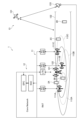
- FIG. 1 schematically shows an overview of a wireless communication system 1 to which a communication control device according to this embodiment is applied.
- the wireless communication system 1 uses NR (New Radio) or 5G NR (Fifth Generation New Radio) as a radio access technology (RAT: Radio Access Technology), and 5GC (Fifth Generation Core) as a core network (CN: Core Network).
- 5G wireless communication system 11 that conforms to the 5th generation mobile communication system (5G) using It includes a 4G wireless communication system 12 that conforms to the 4th generation mobile communication system (4G) used and a satellite communication system 13 that performs satellite communication via a communication satellite 131 .
- the wireless communication system 1 may include a wireless communication system of generations before 4G, may include a wireless communication system of generations after 5G (6G, etc.), and may include Wi-Fi ( It may also include any wireless communication system that is not related to a generation, such as a registered trademark).
- the 5G wireless communication system 11 is installed on the ground and can communicate with communication devices 2A, 2B, 2C, 2D (hereinafter collectively referred to as communication devices 2) such as smartphones, which are also called UE (User Equipment), and 5G NR.
- communication devices 2A, 2B, 2C, 2D such as smartphones, which are also called UE (User Equipment), and 5G NR.
- 5G base stations 111A, 111B, and 111C (hereinafter collectively referred to as 5G base stations 111).
- a base station 111 in 5G is also called a gNodeB (gNB).
- the coverage or support area of each 5G base station 111A, 111B, 111C is called a cell and illustrated as 112A, 112B, 112C, respectively (hereinafter sometimes collectively referred to as 5G cell 112).
- the size of the 5G cell 112 of each 5G base station 111 is arbitrary, but typically ranges from several meters to tens of kilometers in radius. Although there is no established definition, cells with radii of a few meters to tens of meters are called femtocells, cells with radii of tens of meters to tens of meters are called picocells, and cells with radii of tens of meters to hundreds of meters are called microcells. A cell with a radius exceeding several hundred meters is sometimes called a macrocell. In 5G, high-frequency radio waves such as millimeter waves are often used, and because of their high linearity, radio waves are blocked by obstacles, shortening the communication range. For this reason, 5G tends to use smaller cells more often than 4G and earlier generations.
- the communication device 2 can perform 5G communication if it is inside at least one of the multiple 5G cells 112A, 112B, and 112C.
- communicator 2B in 5G cells 112A and 112B can communicate with both 5G base stations 111A and 111B via 5G NR.
- the communication device 2C in the 5G cell 112C can communicate with the 5G base station 111C by 5G NR.
- the communicators 2A and 2D are outside of all the 5G cells 112A, 112B, 112C and are therefore unable to communicate by 5G NR.
- 5G communication by 5G NR between each communication device 2 and each 5G base station 111 is managed by 5GC, which is a core network.
- the 5GC exchanges data with each 5G base station 111, exchanges data with external networks such as the EPC, the satellite communication system 13, and the Internet, and manages movement of the communication device 2.
- the 4G wireless communication system 12 includes a plurality of 4G base stations 121 (only one is shown in FIG. 1) that are installed on the ground and can communicate with the communication device 2 by LTE or LTE-Advanced.
- the base station 121 in 4G is also called eNodeB (eNB). Similar to each 5G base station 111 , the coverage or support area of each 4G base station 121 is also referred to as a cell and illustrated as 122 .
- the communication device 2 can perform 4G communication.
- the communication devices 2A and 2B in the 4G cell 122 can communicate with the 4G base station 121 by LTE or LTE-Advanced. Since the communication devices 2C and 2D are outside the 4G cell 122, they are in a state where they cannot perform communication by LTE or LTE-Advanced.
- 4G communication by LTE or LTE-Advanced between each communication device 2 and each 4G base station 121 is managed by EPC, which is a core network.
- the EPC exchanges data with each 4G base station 121, exchanges data with external networks such as the 5GC, the satellite communication system 13, and the Internet, and manages movement of the communication device 2.
- the communication device 2A is in a state capable of 4G communication with the 4G base station 121
- the communication device 2B is in a state of being able to communicate with the 5G base stations 111A and 111B.
- 5G communication and 4G communication with the 4G base station 121 are possible
- the communication device 2C is in a state where 5G communication with the 5G base station 111C is possible. If there are multiple base stations (111A, 111B, 121) that can communicate like the communication device 2B, the one that is determined to be optimal from the viewpoint of communication quality, etc.
- One base station is selected to communicate with the communication device 2B. Also, since the communication device 2D is not in a state capable of communicating with any of the 5G base station 111 and the 4G base station 121, communication is performed by the satellite communication system 13 described below.
- the satellite communication system 13 is a wireless communication system that uses a communication satellite 131 as a low-orbit satellite that flies in low-orbit space at an altitude of about 500 km to 700 km above the earth's surface as a non-ground base station. Similar to 5G base station 111 and 4G base station 121 , the coverage or support area of communication satellite 131 is also referred to as a cell and illustrated as 132 . Thus, a communication satellite 131 as a non-terrestrial base station provides a satellite communication cell 132 as a non-terrestrial communication cell to the ground. If the communication device 2 on the ground is inside the satellite communication cell 132, it can perform satellite communication.
- the communication satellite 131 as a base station in the satellite communication system 13 communicates directly with the communicator 2 in the satellite communication cell 132.
- Wireless communication is possible either directly or indirectly via an aircraft or the like.
- the radio access technology that the communication satellite 131 uses for radio communication with the communication device 2 in the satellite communication cell 132 may be the same 5G NR as the 5G base station 111, or the same LTE or LTE-Advanced as the 4G base station 121. However, it may be any other radio access technology that the communicator 2 is capable of using. Therefore, the communication device 2 does not need to be provided with special functions or parts for satellite communication.
- the satellite communication system 13 includes a gateway 133 as a ground station installed on the ground and capable of communicating with the communication satellite 131 .
- the gateway 133 is equipped with a satellite antenna for communicating with the communication satellite 131, and includes a 5G base station 111 and a 4G base station 121 as terrestrial base stations that constitute a terrestrial network, and 5G NR and LTE that are respective radio access technologies. or connected via other wired or wireless access technologies or interfaces.
- the gateway 133 connects the NTN formed by the communication satellite 131 and the TN formed by the terrestrial base stations 111 and 121 so as to be mutually communicable.
- the communication satellite 131 When the communication satellite 131 performs 5G communication with the communication device 2 in the satellite communication cell 132 by 5G NR, the 5GC connected via the gateway 133 and the 5G base station 111 (or 5G radio access network) in the TN is used as the core network.
- the communication satellite 131 performs 4G communication with the communication device 2 in the satellite communication cell 132 by LTE or LTE-Advanced, it is connected via the gateway 133 and the 4G base station 121 (or 4G radio access network) in the TN.
- EPC EPC as a core network. In this way, appropriate coordination is achieved between different wireless communication systems such as 5G communication, 4G communication, satellite communication, etc. via the gateway 133 .
- Satellite communication by communication satellite 131 is mainly used to cover areas where terrestrial base stations such as 5G base station 111 and 4G base station 121 are not provided or few are provided.
- the communication device 2D located outside the communication cells of all ground base stations communicates with the communication satellite 131.
- the communication devices 2A, 2B, and 2C which are in a state of good communication with any of the ground base stations, are also in the satellite communication cell 132 and can communicate with the communication satellite 131.
- the limited communication resources (including power) of the communication satellite 131 are saved for the communication device 2D and the like.
- the communication satellite 131 directs communication radio waves to the communication device 2D in the satellite communication cell 132 by beamforming, thereby improving communication quality with the communication device 2D.
- the size of the satellite communication cell 132 of the communication satellite 131 as a satellite base station can be arbitrarily set according to the number of beams emitted by the communication satellite 131.
- a 24 km satellite communication cell 132 can be formed.
- satellite communication cells 132 are typically larger than terrestrial communication cells, such as 5G cells 112 and 4G cells 122, and may include one or more 5G cells 112 and/or 4G cells 122 within them.
- the communication satellite 131 flying in space in a low orbit at an altitude of about 500 km to 700 km above the ground is exemplified as a flying non-ground base station. Flying communication satellites and unmanned or manned aircraft flying in the lower (eg, 20 km or so) atmosphere, such as the stratosphere, may be used as non-terrestrial base stations in addition to or instead of communication satellites 131 .
- the radio communication system 1 is a terrestrial network capable of communicating with the communication devices 2 in the terrestrial communication cells 112 and 122 provided on the ground by the terrestrial base stations 111 and 121 installed on the ground.
- TN terrestrial communication cells
- NTN non-terrestrial network
- the communication control device controls the TN and NTN.
- FIG. 2 is a functional block diagram of the communication control device 3 according to this embodiment.
- the communication control device 3 includes a system information acquisition section 31 , a communication device grouping section 32 and a random access information transmission restriction section 33 .
- These functional blocks are realized through cooperation between hardware resources such as the computer's central processing unit, memory, input device, output device, and peripheral devices connected to the computer, and software executed using them. .
- hardware resources such as the computer's central processing unit, memory, input device, output device, and peripheral devices connected to the computer, and software executed using them.
- each of the above functional blocks may be implemented using the hardware resources of a single computer, or may be implemented by combining hardware resources distributed among multiple computers. .
- some or all of the functional blocks of the communication control device 3 are realized distributedly or centrally by computers and processors provided in the communication device 2, the terrestrial base stations 111 and 121, the non-terrestrial base station 131, and the core network CN. You may Particularly in this embodiment, most of the functional blocks of the communication control device 3 are realized by the communication device 2, and the remaining functional blocks are mainly realized by the terrestrial base stations 111 and 121 and the non-terrestrial base station 131.
- the communication device 2 including the system information acquisition unit 31 acquires system information from the downlink frames DL transmitted from the base stations 111, 121, and 131.
- FIG. 2 schematically illustrates the concept of the downlink frame DL adopted in 5G and the like. Specific configurations, numerical values, etc. of the downlink frame DL and the uplink frame UL will be exemplified below in accordance with an operation example in 5G, but the present disclosure does not apply to the downlink frame DL and the uplink frame DL adopting different configurations, numerical values, etc. It is also applicable to link frames UL.
- FIG. 1 schematically illustrates the concept of the downlink frame DL adopted in 5G and the like. Specific configurations, numerical values, etc. of the downlink frame DL and the uplink frame UL will be exemplified below in accordance with an operation example in 5G, but the present disclosure does not apply to the downlink frame DL and the uplink frame DL adopting different configurations, numerical values, etc. It is also applicable to link frames
- the horizontal direction of the downlink frame DL and the uplink frame UL schematically represents the time direction
- the vertical direction of the downlink frame DL and the uplink frame UL schematically represents the frequency direction.
- the downlink frames DL can be sequentially transmitted by the base stations 111, 121, 131 on the right side of FIG. 2 to the transceiver 2 on the left side of FIG.
- the uplink frames UL can be transmitted sequentially by the transceiver 2 on the left side of FIG. 2 to the base stations 111, 121, 131 on the right side of FIG.
- Each downlink frame DL of 10ms length consists of 10 subframes each of 1ms length.
- 1 slot if the subcarrier spacing is 15kHz
- 2 slots if the subcarrier spacing is 30kHz
- 4 slots if the subcarrier spacing is is 60 kHz
- 8 slots if the subcarrier spacing is 120 kHz
- 16 slots if the subcarrier spacing is 240 kHz
- Each slot contains 14 OFDM symbols regardless of subcarrier spacing.
- a plurality of SS/ A Synchronization Signal/Physical Broadcast Channel (PBCH) block is transmitted from a base station 111, 121, 131 to a communication device 2 in a communication cell 112, 122, 132 using a predetermined time-frequency resource in a predetermined subframe. sent.
- the multiple SS/PBCH blocks transmitted in each half-frame correspond to the different beams that the base stations 111, 121, 131 can transmit.
- the four first to fourth SS/PBCH blocks included in each half-frame in the example of FIG. 2 are transmitted by the first to fourth beams emitted by base stations 111, 121 and 131, respectively.
- the SS/PBCH block is a block for the communication device 2 that receives it to establish frame synchronization and acquire system information necessary for establishing connection with the base stations 111, 121, and 131 by random access, which will be described later.
- the SS/PBCH block includes a primary synchronization signal (PSS) and a secondary synchronization signal (SSS: secondary SS) as synchronization signals (SS: Synchronization Signal) for frame synchronization.
- PSS primary synchronization signal
- SSS secondary synchronization signal
- SS Synchronization Signal
- MIB Master Information Block
- basic system information such as the system frame number (SFN: System Frame Number) is transmitted. be done.
- the communication device 2 (system information acquisition unit 31) that has established frame synchronization by SS and has acquired basic system information from the MIB selects type 1 from the physical downlink shared channel (PDSCH: Physical Downlink Shared Channel) specified by the MIB.
- PDSCH Physical Downlink Shared Channel
- SIB1 System Information Block Type 1
- MIB and SIB1 constitute the minimum system information (MSI: Minimum System Information) in 5G, and include all the information necessary for establishing a connection between the communication device 2 and the base stations 111, 121, 131 by random access, which will be described later.
- MSI Minimum System Information
- the system information acquisition unit 31 includes a random access channel identification unit 311.
- the random access channel identification unit 311 identifies a plurality of random access channels through which the communication device 2 can transmit random access information to the base stations 111 , 121 and 131 . Specifically, referring to the MSI (especially SIB1) received by the communication device 2 functioning as the random access channel identification unit 311, in each uplink frame UL that can be transmitted to the base stations 111, 121, and 131, a random Identify the time-frequency region of the Physical Random Access Channel (PRACH) reserved for the transmission of random access preambles as access information.
- PRACH Physical Random Access Channel
- each uplink frame UL with a length of 10 ms consists of 10 subframes each with a length of 1 ms.
- Each uplink frame UL is given a continuous (cyclic) system frame number from “0” to “1023” that can be recognized by the communication device 2 through the MIB received by the system information acquisition unit 31 .
- FIG. 2 schematically illustrates an uplink frame "SFN#1" with a system frame number "1" and an uplink frame "SFN#2" with a system frame number "2".
- part or all of the frequency resources of one or more slots (each slot consists of 14 OFDM symbols) in one uplink frame UL can be reserved as PRACH.
- the slot length is 1 ms, which is the same as the subframe length (when the subcarrier interval is 15 kHz)
- part of the frequency resource of the third slot of the first uplink frame "SFN#1" is Reserved as the first physical random access channel "PRACH#1”
- part of the frequency resource of the second slot of the second uplink frame "SFN#2" is reserved as the second physical random access channel "PRACH#2"
- the communication device 2 functioning as the random access channel identification unit 311 refers to the received SIB1, etc., and selects physical random access channels "PRACH#1" and “PRACH#2" in a series of uplink frames "SFN#1" and “SFN#2". ” in the time-frequency domain.
- a plurality of PRACHs may be reserved in one uplink frame UL.
- the communication control device 3 targets M (for example, 1024) uplink frames "SFN#1", “SFN#2", ...
- the communication device grouping unit 32 selects a plurality of random access groups "UEGP#1 ' and 'UEGP#2'.
- the first random access group "UEGP#1" of the communication device 2 is associated with the first physical random access channel "PRACH#1”
- the second random access group “UEGP#2" of the communication device 2 is associated with the first physical random access channel "PRACH#1”.
- ' is associated with the second physical random access channel 'PRACH#2'.
- n be the number of random access groups of the communication device 2 below.
- the communication device grouping unit 32 divides the communication device identification information of each communication device 2 by the number n of groups included in SIB1 and the like received by the system information acquisition unit 31 from the base stations 111, 121, and 131, Group the communicators 2 into n random access groups.
- a user identification number such as IMSI (International Mobile Subscriber Identity) assigned to the user of the communication device 2 is exemplified. Since the remainder obtained by dividing the IMSI, etc. by the number of groups n (hereinafter also referred to as "IMSI mod n" using the congruence formula) is n different from 0 to n-1, the number of communication devices 2 can be efficiently can be grouped into n random access groups.
- IMSI mod n International Mobile Subscriber Identity
- identification information unique to the communication device 2 such as the phone number, IP address, IMEI (International Mobile Equipment Identity) of the communication device 2 may be used. Also, since it is sufficient to group a large number of communication devices 2 into n random access groups, communication device identification information and other information that can be the same for a plurality of communication devices 2 may be used. For example, a random number or arbitrary constant pre-assigned to each communication device 2 or a random number or arbitrary constant generated by each communication device 2 when performing the processing of the communication device grouping unit 32 is divided by the number of groups n, and the remainder is may be calculated.
- the random access information transmission restriction unit 33 restricts the transmission of random access preambles other than the physical random access channel associated with each random access group for the communication devices 2 grouped into each of the n random access groups. .
- the communication device 2 grouped into the first random access group "UEGP#1” uses the first physical random access channel "PRACH#" associated with the first random access group "UEGP#1". Transmission of random access preambles other than 1” is restricted. That is, the communication device 2 can transmit a random access preamble only on the first physical random access channel "PRACH#1" and cannot transmit a random access preamble on the second physical random access channel "PRACH#2".
- the communication device 2 grouped in the second random access group "UEGP#2" is the second physical random access channel "PRACH#2" associated with the second random access group "UEGP#2".
- the transmission of random access preambles in is restricted. That is, the communication device 2 can transmit a random access preamble only on the second physical random access channel "PRACH#2" and cannot transmit a random access preamble on the first physical random access channel "PRACH#1".
- the random access information transmission restriction unit 33 obtains the system frame number included in the MIB or the like received by the system information acquisition unit 31 from the base stations 111, 121, and 131 for the communication devices 2 grouped into each of the n random access groups.
- the remainder obtained by dividing by the number of groups n (hereinafter also referred to as “SFN mod n” using a congruence formula) is the remainder obtained by dividing IMSI as the communication device identification information of the communication device 2 by the number of groups n (IMSI mod n) to limit the transmission of random access preambles outside of the physical random access channel included in the uplink frame UL.
- the transmission of random access preambles other than the first physical random access channel "PRACH#1" included in the first uplink frame "SFN#1" is restricted.
- IMSI mod n SFN mod n
- SFN mod n includes n random access groups of the communication device 2 formed according to the values (0, 1, ..., n-1) of "IMSI mod n" on the left side, n frame groups in which M (for example, 1024) uplink frames UL with different system frame numbers are grouped according to the value of "SFN mod n" on the right side (0, 1, ..., n-1) It is a one-to-one operation. That is, the communication device grouping unit 32 groups each communication device 2 into n random access groups corresponding to n frame groups. Then, the random access information transmission restriction unit 33, for the communication device 2 grouped into each of the n random access groups, performs physical random Restrict transmission of random access preambles on non-access channels.
- the equation "IMSI mod n SFN mod n" associated n random access groups of transceiver 2 with n frame groups of uplink frames UL, as illustrated in FIG.
- the random access group is directly associated with the random access channel group instead of being indirectly associated with the random access channel group via the frame group as in the above example.
- FIG. 3 shows specific examples.
- this embodiment assigns five communicators “UE1” to “UE5” having five consecutive IMSIs “1013016041741” to “1013016041745” to system frame numbers “768” to “770”. is assigned or mapped to the physical random access channel in the three uplink frames with The number of groups n in this embodiment is "3" as also shown in FIG.
- IMSI mod n and “SFN mod n” are calculated based on the communication device identification information (IMSI), system frame number (SFN), and number of groups (n) of each communication device 2, and whether they match ( TRUE) or not (FALSE) is determined. Only combinations of communication device identification information (IMSI) and system frame number (SFN) that result in a determination result of “TRUE” are allowed for random access by the communication device 2 .
- communication devices "UE2" and “UE5" grouped into the 0th random access group “UEGP#0" with “IMSI mod n” set to “0” have "SFN mod Transmit a random access preamble to the 0th physical random access channel "PRACH Window#0" that is associated with the uplink frame with the system frame number "768" in which "n” is “0” and included in the uplink frame. Yes (random access preambles cannot be sent for other physical random access channels "PRACH Window#1" and "PRACH Window#2").
- the communication device “UE3" grouped in the first random access group “UEGP#1” with “IMSI mod n” of “1” has a system frame number with “SFN mod n” of "1".
- a random access preamble can be transmitted to the first physical random access channel "PRACH Window#1" that is associated with the "769" uplink frame and included in the uplink frame (other physical random access channel “PRACH Window #0” and “PRACH Window#2” cannot be sent random access preambles).
- the communication devices “UE1” and “UE4" grouped in the second random access group “UEGP#2” with “IMSI mod n" of "2” are systems with "SFN mod n" of "2".
- a random access preamble can be transmitted to the second physical random access channel "PRACH Window #2" that is associated with the uplink frame with the frame number "770" and included in the uplink frame (another physical random access channel " Random access preambles cannot be sent for PRACH Window#0 and PRACH Window#1).
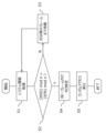
- FIG. 6 is a flowchart of random access control by the communication control device 3.
- "S” in the description of the flowchart means step or process.
- the system information acquisition unit 31 acquires system information from the downlink frames DL transmitted from the base stations 111 , 121 , 131 .
- the communication device grouping unit 32 and the random access information transmission restriction unit 33 combine the system frame number (SFN) and the number of groups (n) included in the system information such as the MIB and SIB1 acquired in S1 and the communication device 2
- the communication device 2 for which "IMSI mod n SFN mod n" holds for the current uplink frame (Yes in S2) proceeds to S4, and the random access channel identification unit 311 detects the random access channel (RO: RACH Occasion).
- the communication device 2 transmits a random access preamble to the base stations 111, 121, 131 on the random access channel identified at S4.
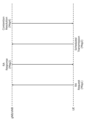
- FIG. 7 schematically shows a contention-based random access (CBRA: Contention Based Random Access) procedure between the communication device 2 and the terrestrial base stations 111 and 121.
- the CBRA procedure consists of four messages exchanged between the communication device 2 (UE) and the ground base stations 111, 121 (gNB/eNB).
- the first message (Msg1) is a random access request (RA Request) that the communication device 2 transmits to the ground base stations 111 and 121.
- RA Request random access request
- a communication device 2 attempting random access for connection establishment to the terrestrial base stations 111 and 121 receives a maximum of 64 mutually orthogonal predetermined random access preambles (below, simply preambles ) is selected and transmitted in the first message to the corresponding terrestrial base station 111, 121 on the physical random access channel.
- the second message is a random access response (RA Response) that the ground base stations 111 and 121 transmit to the communication device 2.
- RA Response random access response
- the ground base stations 111 and 121 that have received the preamble from the communication device 2 through the physical random access channel do not have another communication device 2 that has transmitted the same preamble to the ground base stations 111 and 121 on the same physical random access channel (If there is no collision of preambles), a random access response (hereinafter simply referred to as a response) is transmitted to the communication device 2, and the subsequent steps of establishing a connection using the third and fourth messages are performed.
- the terrestrial base stations 111 and 121 transmit responses to only one communication device 2. , which transmits a response permitting transition to the connection establishment step only to one communication device 2, and transmits a response instructing a waiting time until the next random access to the other communication devices 2, any of the communication devices 2 take measures such as not sending a response to The communication device 2 that has not received a normal response from the terrestrial base stations 111 and 121 needs to wait until another physical random access channel after that.
- the interval between temporally adjacent physical random access channels is about the frame length (10 ms) of the uplink frame UL, and this corresponds to the delay time of each communication device 2 accompanying at least one PRACH wait. Become.
- a "congestion" (hereinafter also referred to as PRACH congestion) may occur due to the communication device 2 waiting for PRACH. That is, one physical random access channel can only accept up to 64 different (orthogonal) preambles, and each communication device 2 randomly selects one preamble. The preamble to be transmitted cannot be known in advance. Therefore, when the number of communication devices 2 attempting random access at the same time increases, preamble collisions occur frequently, in which a plurality of communication devices 2 select the same preamble, causing serious PRACH congestion.
- PRACH congestion may occur due to the communication device 2 waiting for PRACH. That is, one physical random access channel can only accept up to 64 different (orthogonal) preambles, and each communication device 2 randomly selects one preamble. The preamble to be transmitted cannot be known in advance. Therefore, when the number of communication devices 2 attempting random access at the same time increases, preamble collisions occur frequently, in which a plurality of communication devices 2 select the same preamble, causing serious PRACH congestion
- each random access group “UEGP#1" and “UEGP#2” Transmission of preambles to the base stations 111, 121, and 131 is restricted except for the physical random access channels "PRACH#1" and "PRACH#2" corresponding to .
- the communication device 2 that has received a normal response (second message) from the ground base stations 111 and 121 receives the timing information and scheduling permission (available for transmission of the third message during the uplink frame UL) included in the second message.
- the third message (Msg3) is transmitted to the ground base stations 111 and 121.
- the third message includes the communication device identification information of the communication device 2 and the like.
- the terrestrial base stations 111 and 121 that have received the third message identify or authenticate the communication device 2 based on the communication device identification information or the like while appropriately cooperating with the core network CN, and send the notification of completion to the fourth message (Msg4). is transmitted to the communication device 2 as Through the above series of normal exchanges of four messages, the connection between the communication device 2 and the ground base stations 111, 121 is established.
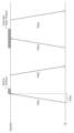
- FIG. 8 schematically shows the CBRA procedure between the communication device 2 and the communication satellite 131 as a non-terrestrial base station. Similar to FIG. 7 for terrestrial base stations 111, 121, the CBRA procedure consists of four messages exchanged between communication unit 2 (UE) and communication satellite 131 (Satellite). Due to the large distance between communicator 2 and communication satellite 131, each message communication involves a non-negligible propagation delay (typically greater than 20ms). Therefore, the communication device 2 that transmits the first message and the third message to the communication satellite 131 communicates with itself based on its own positioning information and the orbital information of the communication satellite 131 by GNSS (Global Navigation Satellite System) or the like. Calculate the distance or propagation delay between satellites 131 .
- GNSS Global Navigation Satellite System
- the communication device 2 transmits each message at an early timing considering the propagation delay so that each message reaches the message window for receiving the third message in a timely manner.
- the length of the message window for receiving the third message (the length of PUSCH set for communication of the third message) is set so that the third message from the communication device 2 can be reliably received. is larger than for the terrestrial base stations 111,121.
- the CBRA procedure for communication satellite 131 takes longer due to propagation delays and consumes more resources for reliable message communication than the CBRA procedure for terrestrial base stations 111,121. Therefore, in the NTN configured by the communication satellite 131, PRACH congestion is more likely to occur and worsen than in the TN in FIG. For this reason, as in the present embodiment described with reference to FIG. It is extremely important that the restriction reduces the possibility that preambles of multiple communication devices 2 conflict or collide on the same physical random access channel "PRACH#1" and "PRACH#2".
- PRACH congestion in NTN occurs, for example, when a large number of NB-IoT devices (communication device 2) that intermittently receive signals according to the DRX (Discontinuous Reception) cycle simultaneously shift or start from the standby state to the signal reception state. can occur. That is, a large number of NB-IoT devices activated simultaneously may simultaneously transmit duplicate preambles on the same physical random access channel.
- PRACH congestion in the NTN can also be caused by discontinuities in non-terrestrial communication cells provided to the ground by non-terrestrial base stations such as communication satellite 131 . For example, if a second communication satellite flies to follow a first communication satellite and there is a gap between the first satellite communication cell of the first communication satellite and the second satellite communication cell of the second communication satellite. , a large number of communicators disconnected from the first satellite cell by the departure of the first communication satellite may simultaneously attempt random access to a second communication satellite that flies in later.
- FIGS. 7 and 8 show a four-step CBRA procedure composed of four messages
- this embodiment can also be applied to a two-step CBRA procedure composed of two messages.
- the information corresponding to the third message in the 4-step CBRA procedure is included in the first message
- the information corresponding to the fourth message in the 4-step CBRA procedure is included in the second message.
- the propagation delay can be minimized by a two-step CBRA procedure with a minimized number of messages.
- the two-step CBRA procedure if the preambles of a plurality of communication devices 2 collide, resources used for transmitting information corresponding to the third message may be wasted.
- the possibility of preamble collision can be reduced, so the propagation delay can be minimized while using resources efficiently.
- Figures 9 and 10 show trial calculation results regarding PRACH congestion in NTN when the present embodiment described with respect to Figure 2 and the like is not applied.
- a communication satellite 131 that flies in a geosynchronous orbit (GEO) at an altitude of about 36,000 km above the earth's surface, and a low earth orbit (LEO: Low Earth Orbit) at an altitude of 2,000 km or less above the earth's surface.
- GEO geosynchronous orbit
- LEO Low Earth Orbit
- FIG. 9 shows the wider the communicable range of a GEO satellite and the higher the random access frequency of each communication device 2, the lower the density of communication devices 2 that each communication satellite 131 can support. Become. Supportable communication device densities of less than "500 UE/km 2 ", which are considered unfavorable for practical use, are highlighted in bold letters and bold frames.
- FIG. 10 shows the conditions specified in "3GPP TR 38.821 Section 7.2.1.1.1.2" in addition to FIG. (more than 2 times) is added. Compared to FIG. 9, especially for GEO satellites with a wide communication range, the supportable communication device density is significantly reduced ("0 UE/km", which means that even one communication device 2 cannot be supported). 2 ” in some cases).
- each device described in the embodiments can be realized by hardware resources or software resources, or by cooperation between hardware resources and software resources.
- Processors, ROMs, RAMs, and other LSIs can be used as hardware resources.
- Programs such as operating systems and applications can be used as software resources.
- Item 1 a random access channel identification unit that identifies a plurality of random access channels on which the communication device can transmit random access information to the base station; a communicator grouping unit that groups each communicator into a plurality of random access groups associated with different portions of the plurality of random access channels; a random access information transmission restriction unit that restricts the transmission of random access information for the communication devices grouped in each random access group on channels other than the random access channel associated with each random access group;
- a communication control device comprising: Item 2: A plurality of frames in which the communication device can transmit information to the base station are grouped into n (n is a natural number of 2 or more) frame groups, The communication device grouping unit groups each communication device into n random access groups corresponding to the n frame groups; The random access information transmission restriction unit provides, for the communication devices grouped in each random access group, random access information other than the random access channel included in the frame belonging to the frame group associated with each random access group.
- a communication control device according to item 1.
- Item 3 The communication device grouping unit groups each communication device into n random access groups according to a remainder obtained by dividing the communication device identification information of each communication device by n;
- the random access information transmission restricting unit controls, for the communication devices grouped into each random access group, the random access information included in the frame in which the remainder when the frame number is divided by n is equal to the remainder when the communication device identification information is divided by n. restrict the transmission of random access information outside the access channel, 3.
- a communication control device according to item 2.
- Item 4 4. The communication control device according to item 3, wherein the communication device identification information is a user identification number given to a user of the communication device.
- Item 5 The communication device grouping unit is provided in each communication device and groups itself into a random access group according to a remainder obtained by dividing its own communication device identification information by n;
- the random access information transmission restriction unit is provided in each communication device, and the remainder obtained by dividing the frame number calculated based on the frame number received from the base station and the number of groups n is the remainder obtained by dividing the own communication device identification information by n. limiting the transmission of random access information outside of the random access channel contained in frames equal to the remainder; 5.
- a communication control device according to item 3 or 4.
- Item 6 6. The communication control device according to any one of items 1 to 5, wherein the random access channel specifying unit, the communication device grouping unit, and the random access information transmission restriction unit are provided in each communication device.
- the communication control device according to any one of items 1 to 6, wherein the base station is a flying non-terrestrial base station.
- Item 8 The communication control device according to item 7, wherein the non-ground base station is a communication satellite that flies in outer space.
- Item 9 The plurality of random access channels are grouped into n (n is a natural number of 2 or more) random access channel groups, The communication device grouping unit groups each communication device into n random access groups corresponding to the n random access channel groups; The random access information transmission restriction unit restricts the communication devices grouped in each random access group from transmitting random access information on channels other than random access channels belonging to the random access channel group associated with each random access group. Restrict, 9. The communication control device according to any one of items 1 to 8.
- the communication device grouping unit groups each communication device into n random access groups according to a remainder obtained by dividing the communication device identification information of each communication device by n;
- the random access information transmission restriction unit performs random access such that the remainder of dividing the random access channel identification information by n is equal to the remainder of dividing the communication device identification information by n for the communication devices grouped into each of the random access groups. restrict the transmission of random access information outside the channel,
- a communication control device according to item 9.
- Item 11 identifying a plurality of random access channels over which the communicator can transmit random access information to the base station; grouping each communicator into a plurality of random access groups associated with different portions of the plurality of random access channels; Restricting the transmission of random access information other than the random access channel associated with each random access group for the communication devices grouped in each random access group;
- a communication control method comprising: Item 12: identifying a plurality of random access channels over which the communicator can transmit random access information to the base station; grouping each communicator into a plurality of random access groups associated with different portions of the plurality of random access channels; Restricting the transmission of random access information other than the random access channel associated with each random access group for the communication devices grouped in each random access group;
- a storage medium storing a communication control program that causes a computer to execute
- the present disclosure relates to random access control in communication systems.
Landscapes
- Engineering & Computer Science (AREA)
- Computer Networks & Wireless Communication (AREA)
- Signal Processing (AREA)
- Physics & Mathematics (AREA)
- Astronomy & Astrophysics (AREA)
- General Physics & Mathematics (AREA)
- Computer Security & Cryptography (AREA)
- Mobile Radio Communication Systems (AREA)
Abstract
Description
通信機が基地局に対してランダムアクセス情報を送信可能な複数のランダムアクセスチャネルを特定するランダムアクセスチャネル特定部と、
前記複数のランダムアクセスチャネルの異なる複数の部分に対応付けられる複数のランダムアクセスグループに各通信機をグルーピングする通信機グルーピング部と、
前記各ランダムアクセスグループにグルーピングされた通信機について、当該各ランダムアクセスグループに対応付けられたランダムアクセスチャネル以外でのランダムアクセス情報の送信を制限するランダムアクセス情報送信制限部と、
を備える通信制御装置。
項目2:
通信機が基地局に対して情報を送信可能な複数のフレームは、n個(nは2以上の自然数)のフレームグループにグルーピングされ、
前記通信機グルーピング部は、前記n個のフレームグループに対応するn個のランダムアクセスグループに各通信機をグルーピングし、
前記ランダムアクセス情報送信制限部は、前記各ランダムアクセスグループにグルーピングされた通信機について、当該各ランダムアクセスグループに対応付けられたフレームグループに属するフレームに含まれるランダムアクセスチャネル以外でのランダムアクセス情報の送信を制限する、
項目1に記載の通信制御装置。
項目3:
前記通信機グルーピング部は、各通信機の通信機識別情報をnで割った余りに応じてn個のランダムアクセスグループに当該各通信機をグルーピングし、
前記ランダムアクセス情報送信制限部は、前記各ランダムアクセスグループにグルーピングされた通信機について、フレーム番号をnで割った余りが前記通信機識別情報をnで割った余りと等しくなるフレームに含まれるランダムアクセスチャネル以外でのランダムアクセス情報の送信を制限する、
項目2に記載の通信制御装置。
項目4:
前記通信機識別情報は、通信機のユーザに付与されているユーザ識別番号である、項目3に記載の通信制御装置。
項目5:
前記通信機グルーピング部は各通信機に設けられ、自身の通信機識別情報をnで割った余りに応じたランダムアクセスグループに自身をグルーピングし、
前記ランダムアクセス情報送信制限部は各通信機に設けられ、基地局から受信したフレーム番号およびグループ数nに基づいて演算したフレーム番号をnで割った余りが自身の通信機識別情報をnで割った余りと等しくなるフレームに含まれるランダムアクセスチャネル以外でのランダムアクセス情報の送信を制限する、
項目3または4に記載の通信制御装置。
項目6:
前記ランダムアクセスチャネル特定部、前記通信機グルーピング部、ランダムアクセス情報送信制限部は、各通信機に設けられる、項目1から5のいずれかに記載の通信制御装置。
項目7:
前記基地局は飛行する非地上基地局である、項目1から6のいずれかに記載の通信制御装置。
項目8:
前記非地上基地局は宇宙空間を飛行する通信衛星である、項目7に記載の通信制御装置。
項目9:
前記複数のランダムアクセスチャネルは、n個(nは2以上の自然数)のランダムアクセスチャネルグループにグルーピングされ、
前記通信機グルーピング部は、前記n個のランダムアクセスチャネルグループに対応するn個のランダムアクセスグループに各通信機をグルーピングし、
前記ランダムアクセス情報送信制限部は、前記各ランダムアクセスグループにグルーピングされた通信機について、当該各ランダムアクセスグループに対応付けられたランダムアクセスチャネルグループに属するランダムアクセスチャネル以外でのランダムアクセス情報の送信を制限する、
項目1から8のいずれかに記載の通信制御装置。
項目10:
前記通信機グルーピング部は、各通信機の通信機識別情報をnで割った余りに応じてn個のランダムアクセスグループに当該各通信機をグルーピングし、
前記ランダムアクセス情報送信制限部は、前記各ランダムアクセスグループにグルーピングされた通信機について、ランダムアクセスチャネル識別情報をnで割った余りが前記通信機識別情報をnで割った余りと等しくなるランダムアクセスチャネル以外でのランダムアクセス情報の送信を制限する、
項目9に記載の通信制御装置。
項目11:
通信機が基地局に対してランダムアクセス情報を送信可能な複数のランダムアクセスチャネルを特定することと、
前記複数のランダムアクセスチャネルの異なる複数の部分に対応付けられる複数のランダムアクセスグループに各通信機をグルーピングすることと、
前記各ランダムアクセスグループにグルーピングされた通信機について、当該各ランダムアクセスグループに対応付けられたランダムアクセスチャネル以外でのランダムアクセス情報の送信を制限することと、
を備える通信制御方法。
項目12:
通信機が基地局に対してランダムアクセス情報を送信可能な複数のランダムアクセスチャネルを特定することと、
前記複数のランダムアクセスチャネルの異なる複数の部分に対応付けられる複数のランダムアクセスグループに各通信機をグルーピングすることと、
前記各ランダムアクセスグループにグルーピングされた通信機について、当該各ランダムアクセスグループに対応付けられたランダムアクセスチャネル以外でのランダムアクセス情報の送信を制限することと、
をコンピュータに実行させる通信制御プログラムを記憶した記憶媒体。 Item 1:
a random access channel identification unit that identifies a plurality of random access channels on which the communication device can transmit random access information to the base station;
a communicator grouping unit that groups each communicator into a plurality of random access groups associated with different portions of the plurality of random access channels;
a random access information transmission restriction unit that restricts the transmission of random access information for the communication devices grouped in each random access group on channels other than the random access channel associated with each random access group;
A communication control device comprising:
Item 2:
A plurality of frames in which the communication device can transmit information to the base station are grouped into n (n is a natural number of 2 or more) frame groups,
The communication device grouping unit groups each communication device into n random access groups corresponding to the n frame groups;
The random access information transmission restriction unit provides, for the communication devices grouped in each random access group, random access information other than the random access channel included in the frame belonging to the frame group associated with each random access group. restrict transmission,
A communication control device according to
Item 3:
The communication device grouping unit groups each communication device into n random access groups according to a remainder obtained by dividing the communication device identification information of each communication device by n;
The random access information transmission restricting unit controls, for the communication devices grouped into each random access group, the random access information included in the frame in which the remainder when the frame number is divided by n is equal to the remainder when the communication device identification information is divided by n. restrict the transmission of random access information outside the access channel,
3. A communication control device according to
Item 4:
4. The communication control device according to
Item 5:
The communication device grouping unit is provided in each communication device and groups itself into a random access group according to a remainder obtained by dividing its own communication device identification information by n;
The random access information transmission restriction unit is provided in each communication device, and the remainder obtained by dividing the frame number calculated based on the frame number received from the base station and the number of groups n is the remainder obtained by dividing the own communication device identification information by n. limiting the transmission of random access information outside of the random access channel contained in frames equal to the remainder;
5. A communication control device according to
Item 6:
6. The communication control device according to any one of
Item 7:
7. The communication control device according to any one of
Item 8:
The communication control device according to item 7, wherein the non-ground base station is a communication satellite that flies in outer space.
Item 9:
The plurality of random access channels are grouped into n (n is a natural number of 2 or more) random access channel groups,
The communication device grouping unit groups each communication device into n random access groups corresponding to the n random access channel groups;
The random access information transmission restriction unit restricts the communication devices grouped in each random access group from transmitting random access information on channels other than random access channels belonging to the random access channel group associated with each random access group. Restrict,
9. The communication control device according to any one of
Item 10:
The communication device grouping unit groups each communication device into n random access groups according to a remainder obtained by dividing the communication device identification information of each communication device by n;
The random access information transmission restriction unit performs random access such that the remainder of dividing the random access channel identification information by n is equal to the remainder of dividing the communication device identification information by n for the communication devices grouped into each of the random access groups. restrict the transmission of random access information outside the channel,
A communication control device according to
Item 11:
identifying a plurality of random access channels over which the communicator can transmit random access information to the base station;
grouping each communicator into a plurality of random access groups associated with different portions of the plurality of random access channels;
Restricting the transmission of random access information other than the random access channel associated with each random access group for the communication devices grouped in each random access group;
A communication control method comprising:
Item 12:
identifying a plurality of random access channels over which the communicator can transmit random access information to the base station;
grouping each communicator into a plurality of random access groups associated with different portions of the plurality of random access channels;
Restricting the transmission of random access information other than the random access channel associated with each random access group for the communication devices grouped in each random access group;
A storage medium storing a communication control program that causes a computer to execute
Claims (12)
- 通信機が基地局に対してランダムアクセス情報を送信可能な複数のランダムアクセスチャネルを特定するランダムアクセスチャネル特定部と、
前記複数のランダムアクセスチャネルの異なる複数の部分に対応付けられる複数のランダムアクセスグループに各通信機をグルーピングする通信機グルーピング部と、
前記各ランダムアクセスグループにグルーピングされた通信機について、当該各ランダムアクセスグループに対応付けられたランダムアクセスチャネル以外でのランダムアクセス情報の送信を制限するランダムアクセス情報送信制限部と、
を備える通信制御装置。 a random access channel identification unit that identifies a plurality of random access channels on which the communication device can transmit random access information to the base station;
a communicator grouping unit that groups each communicator into a plurality of random access groups associated with different portions of the plurality of random access channels;
a random access information transmission restriction unit that restricts the transmission of random access information for the communication devices grouped in each random access group on channels other than the random access channel associated with each random access group;
A communication control device comprising: - 通信機が基地局に対して情報を送信可能な複数のフレームは、n個(nは2以上の自然数)のフレームグループにグルーピングされ、
前記通信機グルーピング部は、前記n個のフレームグループに対応するn個のランダムアクセスグループに各通信機をグルーピングし、
前記ランダムアクセス情報送信制限部は、前記各ランダムアクセスグループにグルーピングされた通信機について、当該各ランダムアクセスグループに対応付けられたフレームグループに属するフレームに含まれるランダムアクセスチャネル以外でのランダムアクセス情報の送信を制限する、
請求項1に記載の通信制御装置。 A plurality of frames in which the communication device can transmit information to the base station are grouped into n (n is a natural number of 2 or more) frame groups,
The communication device grouping unit groups each communication device into n random access groups corresponding to the n frame groups;
The random access information transmission restriction unit provides, for the communication devices grouped in each random access group, random access information other than the random access channel included in the frame belonging to the frame group associated with each random access group. restrict transmission,
The communication control device according to claim 1. - 前記通信機グルーピング部は、各通信機の通信機識別情報をnで割った余りに応じてn個のランダムアクセスグループに当該各通信機をグルーピングし、
前記ランダムアクセス情報送信制限部は、前記各ランダムアクセスグループにグルーピングされた通信機について、フレーム番号をnで割った余りが前記通信機識別情報をnで割った余りと等しくなるフレームに含まれるランダムアクセスチャネル以外でのランダムアクセス情報の送信を制限する、
請求項2に記載の通信制御装置。 The communication device grouping unit groups each communication device into n random access groups according to a remainder obtained by dividing the communication device identification information of each communication device by n;
The random access information transmission restricting unit controls, for the communication devices grouped into each random access group, the random access information included in the frame in which the remainder when the frame number is divided by n is equal to the remainder when the communication device identification information is divided by n. restrict the transmission of random access information outside the access channel,
3. The communication control device according to claim 2. - 前記通信機識別情報は、通信機のユーザに付与されているユーザ識別番号である、請求項3に記載の通信制御装置。 The communication control apparatus according to claim 3, wherein the communication device identification information is a user identification number given to a user of the communication device.
- 前記通信機グルーピング部は各通信機に設けられ、自身の通信機識別情報をnで割った余りに応じたランダムアクセスグループに自身をグルーピングし、
前記ランダムアクセス情報送信制限部は各通信機に設けられ、基地局から受信したフレーム番号およびグループ数nに基づいて演算したフレーム番号をnで割った余りが自身の通信機識別情報をnで割った余りと等しくなるフレームに含まれるランダムアクセスチャネル以外でのランダムアクセス情報の送信を制限する、
請求項3に記載の通信制御装置。 The communication device grouping unit is provided in each communication device and groups itself into a random access group according to a remainder obtained by dividing its own communication device identification information by n;
The random access information transmission restriction unit is provided in each communication device, and the remainder obtained by dividing the frame number calculated based on the frame number received from the base station and the number of groups n is the remainder obtained by dividing the own communication device identification information by n. limiting the transmission of random access information outside of the random access channel contained in frames equal to the remainder;
4. The communication control device according to claim 3. - 前記ランダムアクセスチャネル特定部、前記通信機グルーピング部、ランダムアクセス情報送信制限部は、各通信機に設けられる、請求項1に記載の通信制御装置。 The communication control device according to claim 1, wherein the random access channel specifying unit, the communication device grouping unit, and the random access information transmission restriction unit are provided in each communication device.
- 前記基地局は飛行する非地上基地局である、請求項1に記載の通信制御装置。 The communication control device according to claim 1, wherein the base station is a flying non-terrestrial base station.
- 前記非地上基地局は宇宙空間を飛行する通信衛星である、請求項7に記載の通信制御装置。 The communication control device according to claim 7, wherein said non-terrestrial base station is a communication satellite that flies in outer space.
- 前記複数のランダムアクセスチャネルは、n個(nは2以上の自然数)のランダムアクセスチャネルグループにグルーピングされ、
前記通信機グルーピング部は、前記n個のランダムアクセスチャネルグループに対応するn個のランダムアクセスグループに各通信機をグルーピングし、
前記ランダムアクセス情報送信制限部は、前記各ランダムアクセスグループにグルーピングされた通信機について、当該各ランダムアクセスグループに対応付けられたランダムアクセスチャネルグループに属するランダムアクセスチャネル以外でのランダムアクセス情報の送信を制限する、
請求項1に記載の通信制御装置。 The plurality of random access channels are grouped into n (n is a natural number of 2 or more) random access channel groups,
The communication device grouping unit groups each communication device into n random access groups corresponding to the n random access channel groups;
The random access information transmission restriction unit restricts the communication devices grouped in each random access group from transmitting random access information on channels other than random access channels belonging to the random access channel group associated with each random access group. Restrict,
The communication control device according to claim 1. - 前記通信機グルーピング部は、各通信機の通信機識別情報をnで割った余りに応じてn個のランダムアクセスグループに当該各通信機をグルーピングし、
前記ランダムアクセス情報送信制限部は、前記各ランダムアクセスグループにグルーピングされた通信機について、ランダムアクセスチャネル識別情報をnで割った余りが前記通信機識別情報をnで割った余りと等しくなるランダムアクセスチャネル以外でのランダムアクセス情報の送信を制限する、
請求項9に記載の通信制御装置。 The communication device grouping unit groups each communication device into n random access groups according to a remainder obtained by dividing the communication device identification information of each communication device by n;
The random access information transmission restriction unit performs random access such that the remainder of dividing the random access channel identification information by n is equal to the remainder of dividing the communication device identification information by n for the communication devices grouped into each of the random access groups. restrict the transmission of random access information outside the channel,
The communication control device according to claim 9. - 通信機が基地局に対してランダムアクセス情報を送信可能な複数のランダムアクセスチャネルを特定することと、
前記複数のランダムアクセスチャネルの異なる複数の部分に対応付けられる複数のランダムアクセスグループに各通信機をグルーピングすることと、
前記各ランダムアクセスグループにグルーピングされた通信機について、当該各ランダムアクセスグループに対応付けられたランダムアクセスチャネル以外でのランダムアクセス情報の送信を制限することと、
を備える通信制御方法。 identifying a plurality of random access channels over which the communicator can transmit random access information to the base station;
grouping each communicator into a plurality of random access groups associated with different portions of the plurality of random access channels;
Restricting the transmission of random access information other than the random access channel associated with each random access group for the communication devices grouped in each random access group;
A communication control method comprising: - 通信機が基地局に対してランダムアクセス情報を送信可能な複数のランダムアクセスチャネルを特定することと、
前記複数のランダムアクセスチャネルの異なる複数の部分に対応付けられる複数のランダムアクセスグループに各通信機をグルーピングすることと、
前記各ランダムアクセスグループにグルーピングされた通信機について、当該各ランダムアクセスグループに対応付けられたランダムアクセスチャネル以外でのランダムアクセス情報の送信を制限することと、
をコンピュータに実行させる通信制御プログラムを記憶している記憶媒体。 identifying a plurality of random access channels over which the communicator can transmit random access information to the base station;
grouping each communicator into a plurality of random access groups associated with different portions of the plurality of random access channels;
Restricting the transmission of random access information other than the random access channel associated with each random access group for the communication devices grouped in each random access group;
A storage medium that stores a communication control program that causes a computer to execute
Priority Applications (2)
| Application Number | Priority Date | Filing Date | Title |
|---|---|---|---|
| JP2023556109A JPWO2023074007A1 (en) | 2021-10-29 | 2022-01-06 | |
| KR1020247001880A KR20240019851A (en) | 2021-10-29 | 2022-01-06 | Random access control in communication systems |
Applications Claiming Priority (2)
| Application Number | Priority Date | Filing Date | Title |
|---|---|---|---|
| JP2021177197 | 2021-10-29 | ||
| JP2021-177197 | 2021-10-29 |
Publications (1)
| Publication Number | Publication Date |
|---|---|
| WO2023074007A1 true WO2023074007A1 (en) | 2023-05-04 |
Family
ID=86159308
Family Applications (1)
| Application Number | Title | Priority Date | Filing Date |
|---|---|---|---|
| PCT/JP2022/000258 WO2023074007A1 (en) | 2021-10-29 | 2022-01-06 | Random access control in communication system |
Country Status (3)
| Country | Link |
|---|---|
| JP (1) | JPWO2023074007A1 (en) |
| KR (1) | KR20240019851A (en) |
| WO (1) | WO2023074007A1 (en) |
Family Cites Families (1)
| Publication number | Priority date | Publication date | Assignee | Title |
|---|---|---|---|---|
| EP2452535A1 (en) | 2009-07-07 | 2012-05-16 | Telefonaktiebolaget LM Ericsson (publ) | Random access procedure utilizing cyclic shift of demodulation reference signal |
-
2022
- 2022-01-06 JP JP2023556109A patent/JPWO2023074007A1/ja active Pending
- 2022-01-06 WO PCT/JP2022/000258 patent/WO2023074007A1/en active Application Filing
- 2022-01-06 KR KR1020247001880A patent/KR20240019851A/en unknown
Non-Patent Citations (2)
| Title |
|---|
| HUAWEI, HISILICON: "Notifications for Multicast and Broadcast", 3GPP TSG-RAN WG2 MEETING #115-E, R2-2108202, 6 August 2021 (2021-08-06), XP052034686 * |
| RAKUTEN MOBILE INC: "PRACH Congestion mitigation in NTN IoT", 3GPP TSG-RAN WG2 MEETING #116-E, R2-2110561, 21 October 2021 (2021-10-21), XP052067006 * |
Also Published As
| Publication number | Publication date |
|---|---|
| KR20240019851A (en) | 2024-02-14 |
| JPWO2023074007A1 (en) | 2023-05-04 |
Similar Documents
| Publication | Publication Date | Title |
|---|---|---|
| EP4203337A1 (en) | Beam failure determination method and apparatus, device, and storage medium | |
| CN108462998B (en) | Base station, user equipment and method for random access | |
| EP3768028B1 (en) | Method and device for communication | |
| US11540324B2 (en) | Variable random access channel contention resolution window in a non-terrestrial network | |
| US20220150968A1 (en) | Configured grants within a transmitter cot | |
| CN102083228A (en) | Random access method and equipment for relay system | |
| CN102158980B (en) | Random access method based on return link, device and system | |
| US20230239774A1 (en) | Network slicing information processing method, terminal device, and network device | |
| CN112544118A (en) | Method, apparatus and computer readable medium for random access | |
| US20240015796A1 (en) | Ue coverage enhancements | |
| US20230180300A1 (en) | First message differentiation in cfra procedure | |
| EP3678441B1 (en) | Improving access procedure | |
| CN114982363A (en) | Joint processing of random access channel communications | |
| US20180376514A1 (en) | Methods of uplink broadcast, terminal device, and network node | |
| WO2023074007A1 (en) | Random access control in communication system | |
| EP4115673B1 (en) | Sharing of txop based on spatial multiplexing | |
| US20240137987A1 (en) | Random access control in communication system | |
| WO2018226129A1 (en) | Handling access to a wireless communications network | |
| EP4319445A1 (en) | Communication method and apparatus | |
| US20240155692A1 (en) | Communication method, terminal device and network device | |
| US20230292210A1 (en) | Device and method for transmitting/receiving data in non-terrestrial and terrestrial network systems | |
| WO2024029422A1 (en) | Communication system | |
| KR20220009882A (en) | Apparatus and method for transmitting and receiving data in non-terrestrial and terrestrial network system | |
| KR20230069924A (en) | Improved monitoring of random access | |
| CN117596707A (en) | Communication method, terminal, network device, system and storage medium |
Legal Events
| Date | Code | Title | Description |
|---|---|---|---|
| WWE | Wipo information: entry into national phase |
Ref document number: 18001873 Country of ref document: US |
|
| 121 | Ep: the epo has been informed by wipo that ep was designated in this application |
Ref document number: 22886344 Country of ref document: EP Kind code of ref document: A1 |
|
| WWE | Wipo information: entry into national phase |
Ref document number: 2023556109 Country of ref document: JP |
|
| ENP | Entry into the national phase |
Ref document number: 20247001880 Country of ref document: KR Kind code of ref document: A |
|
| WWE | Wipo information: entry into national phase |
Ref document number: 1020247001880 Country of ref document: KR |