WO2023073898A1 - Terminal et procédé de communication - Google Patents
Terminal et procédé de communication Download PDFInfo
- Publication number
- WO2023073898A1 WO2023073898A1 PCT/JP2021/039927 JP2021039927W WO2023073898A1 WO 2023073898 A1 WO2023073898 A1 WO 2023073898A1 JP 2021039927 W JP2021039927 W JP 2021039927W WO 2023073898 A1 WO2023073898 A1 WO 2023073898A1
- Authority
- WO
- WIPO (PCT)
- Prior art keywords
- terminal
- information
- base station
- pusch
- transmission
- Prior art date
Links
- 238000004891 communication Methods 0.000 title claims description 65
- 238000000034 method Methods 0.000 title claims description 65
- 230000005540 biological transmission Effects 0.000 abstract description 86
- 238000010586 diagram Methods 0.000 description 27
- 238000012545 processing Methods 0.000 description 19
- 230000006870 function Effects 0.000 description 16
- 238000005516 engineering process Methods 0.000 description 9
- 238000001514 detection method Methods 0.000 description 7
- 230000008569 process Effects 0.000 description 7
- 230000011664 signaling Effects 0.000 description 6
- 230000001133 acceleration Effects 0.000 description 5
- 238000010295 mobile communication Methods 0.000 description 4
- 238000012986 modification Methods 0.000 description 4
- 230000004048 modification Effects 0.000 description 4
- 230000008054 signal transmission Effects 0.000 description 4
- 230000004913 activation Effects 0.000 description 3
- 238000013473 artificial intelligence Methods 0.000 description 3
- 238000013507 mapping Methods 0.000 description 3
- 230000000737 periodic effect Effects 0.000 description 3
- 230000009471 action Effects 0.000 description 2
- 238000007630 basic procedure Methods 0.000 description 2
- 230000008878 coupling Effects 0.000 description 2
- 238000010168 coupling process Methods 0.000 description 2
- 238000005859 coupling reaction Methods 0.000 description 2
- 125000004122 cyclic group Chemical group 0.000 description 2
- 230000007774 longterm Effects 0.000 description 2
- 238000005259 measurement Methods 0.000 description 2
- 230000003287 optical effect Effects 0.000 description 2
- 238000013468 resource allocation Methods 0.000 description 2
- 230000006978 adaptation Effects 0.000 description 1
- 230000002776 aggregation Effects 0.000 description 1
- 238000004220 aggregation Methods 0.000 description 1
- 238000003491 array Methods 0.000 description 1
- 230000006399 behavior Effects 0.000 description 1
- 238000004364 calculation method Methods 0.000 description 1
- 239000003795 chemical substances by application Substances 0.000 description 1
- 230000005059 dormancy Effects 0.000 description 1
- 230000009977 dual effect Effects 0.000 description 1
- 239000000835 fiber Substances 0.000 description 1
- 238000001914 filtration Methods 0.000 description 1
- 239000006249 magnetic particle Substances 0.000 description 1
- 238000007726 management method Methods 0.000 description 1
- 239000011159 matrix material Substances 0.000 description 1
- 230000002093 peripheral effect Effects 0.000 description 1
- 230000004044 response Effects 0.000 description 1
- 239000013589 supplement Substances 0.000 description 1
- 238000013519 translation Methods 0.000 description 1
Images


Classifications
-
- H—ELECTRICITY
- H04—ELECTRIC COMMUNICATION TECHNIQUE
- H04W—WIRELESS COMMUNICATION NETWORKS
- H04W72/00—Local resource management
- H04W72/12—Wireless traffic scheduling
Definitions
- the present invention relates to a terminal and communication method in a wireless communication system.
- NR New Radio
- LTE Long Term Evolution
- NR a technology is being studied that enables free allocation of an uplink control channel (PUCCH: Physical Uplink Control Channel) and an uplink shared channel (PUSCH: Physical Uplink Shared Channel) within a slot. Also, in NR, a technique for transmitting uplink control information (UCI) as a physical layer signal via PUCCH or PUSCH is being studied for LTE.
- PUCCH Physical Uplink Control Channel
- PUSCH Physical Uplink Shared Channel
- the present invention has been made in view of the above points, and aims at facilitating the implementation of terminals related to transmission of uplink information.
- a receiving unit that receives information from a base station indicating which multiplexing group to multiplex uplink information into, a control unit that multiplexes the uplink information for each multiplexing group, and and a transmitting unit configured to transmit the uplink information to the base station.
- a technique that facilitates implementation of terminals related to transmission of uplink information.
- FIG. 10 is a sequence diagram showing an example of the flow of dynamic grant processing;
- FIG. 10 is a sequence diagram showing an example of the flow of processing for Configured Grant;
- FIG. 4 is a diagram for explaining a control procedure for collisions between PUCCH and PUSCH;
- FIG. 4 is a diagram for explaining a HARQ-ACK transmission method according to option 1-1 of the first embodiment;
- FIG. 10 is a diagram for explaining an SR transmission method according to Option 1-2 of Example 1;
- FIG. 10 is a diagram for explaining a CSI transmission method according to option 1-3 of the first embodiment;
- FIG. 4 is a diagram for explaining a UCI transmission method according to option 1-4 of the first embodiment
- FIG. 11 is a diagram for explaining a method of multiplexing uplink information according to the second embodiment
- FIG. 11 is a diagram for explaining simultaneous transmission of uplink information according to the third embodiment
- It is a figure showing an example of functional composition of a base station concerning an embodiment of the invention. It is a figure which shows an example of the functional structure of the terminal which concerns on embodiment of this invention. It is a figure which shows an example of the hardware configuration of the base station or terminal which concerns on embodiment of this invention. It is a figure showing an example of composition of vehicles concerning an embodiment of the invention.
- existing technology may be used as appropriate.
- the existing technology is, for example, existing NR or LTE, but is not limited to existing NR or LTE.
- LTE Long Term Evolution
- LTE-Advanced and LTE-Advanced and subsequent systems eg, NR
- SS Synchronization signal
- PSS Primary SS
- SSS Secondary SS
- PBCH Physical broadcast channel
- PRACH Physical random access channel
- PDCCH Physical Downlink Control Channel
- PDSCH Physical Downlink Shared Channel
- PUCCH Physical Uplink Control Channel
- PUSCH Physical Uplink Shared Channel
- the duplex system may be a TDD (Time Division Duplex) system, an FDD (Frequency Division Duplex) system, or other (for example, Flexible Duplex etc.) method may be used.
- TDD Time Division Duplex
- FDD Frequency Division Duplex
- configure of wireless parameters and the like may mean that predetermined values are pre-configured (pre-configured).
- the wireless parameters notified from may be set.
- FIG. 1 is a diagram for explaining a radio communication system according to an embodiment of the present invention.
- a radio communication system according to an embodiment of the present invention includes a base station 10 and a terminal 20, as shown in FIG. Although one base station 10 and one terminal 20 are shown in FIG. 1, this is an example and there may be more than one.
- the base station 10 is a communication device that provides one or more cells and performs wireless communication with the terminal 20.
- Physical resources of radio signals are defined in the time domain and the frequency domain.
- the time domain may be defined by the number of OFDM (Orthogonal Frequency Division Multiplexing) symbols, and the frequency domain is defined by the number of subcarriers or resource blocks. good too.
- a TTI Transmission Time Interval
- a slot or a TTI may be a subframe.
- the base station 10 transmits the synchronization signal and system information to the terminal 20.
- Synchronization signals are, for example, NR-PSS and NR-SSS.
- the system information is transmitted by, for example, NR-PBCH, and is also called broadcast information.
- the synchronization signal and system information may be called SSB (SS/PBCH block).
- the base station 10 transmits control signals or data to the terminal 20 on DL (Downlink) and receives control signals or data from the terminal 20 on UL (Uplink).
- Both the base station 10 and the terminal 20 can perform beamforming to transmit and receive signals.
- both the base station 10 and the terminal 20 can apply MIMO (Multiple Input Multiple Output) communication to DL or UL.
- MIMO Multiple Input Multiple Output
- both the base station 10 and the terminal 20 may communicate via a secondary cell (SCell: Secondary Cell) and a primary cell (PCell: Primary Cell) by CA (Carrier Aggregation).
- SCell Secondary Cell
- PCell Primary Cell
- CA Carrier Aggregation
- the terminal 20 may communicate via a primary cell of the base station 10 and a primary secondary cell group cell (PSCell: Primary SCG Cell) of another base station 10 by DC (Dual Connectivity).
- DC Dual Connectivity
- the terminal 20 is a communication device with a wireless communication function, such as a smartphone, mobile phone, tablet, wearable terminal, or M2M (Machine-to-Machine) communication module. As shown in FIG. 1 , the terminal 20 receives control signals or data from the base station 10 on the DL and transmits control signals or data to the base station 10 on the UL, thereby performing various functions provided by the wireless communication system. Use communication services. Also, the terminal 20 receives various reference signals transmitted from the base station 10, and measures channel quality based on the reception result of the reference signals. Note that the terminal 20 may be called UE, and the base station 10 may be called gNB.
- FIG. 2 is a diagram showing a basic procedure example in the embodiment of the present invention. First, a basic operation example in the wireless communication system of this embodiment will be described with reference to FIG.
- the terminal 20 transmits capability information (UE capability) to the base station 10. Based on this capability information, the base station 10 can determine the content of information to be transmitted to the terminal 20 in S101 and S102 below, for example.
- UE capability capability information
- the base station 10 transmits configuration information to the terminal 20 by means of an RRC message, and the terminal 20 receives the configuration information.
- the setting information is, for example, setting information regarding a set of K1 and a TDRA table, which will be described later. Note that both the set of K1 and the TDRA table may be notified from the base station 10 to the terminal 20, or may be predetermined by specifications or the like, and the base station 10 and the terminal 20 may may be used. Also, the TDRA table may be called time domain resource allocation configuration information.
- the base station 10 transmits scheduling (assignment information) for one or more PDSCHs by DCI to the terminal 20, and the terminal 20 receives the DCI.
- the DCI also contains information about uplink resources for transmitting HARQ-ACK information.
- the terminal 20 receives PDSCH based on the scheduling information in DCI, and transmits HARQ-ACK information to the base station 10 in S104.
- Base station 10 receives the HARQ-ACK information.
- the PDSCH may be a PDSCH received without a corresponding DCI, eg, a PDSCH received in a periodic PDSCH reception function called semi-persistent scheduling (SPS).
- SPS semi-persistent scheduling
- Dynamic grant is a procedure in which scheduling is performed according to a scheduling request from a terminal.
- Configured grant is a procedure in which scheduling is performed by omitting scheduling requests from terminals in order to reduce uplink delay.
- FIG. 3 is a sequence diagram showing an example of the dynamic grant processing flow.
- the terminal 20 transmits a schedule request to the base station 10 when uplink data is generated (step S11).
- the base station 10 transmits a signal indicating uplink permission to the terminal 20 in response to the received schedule request (step S12).
- the terminal 20 transmits BSR (Buffer Status Report) and/or uplink data to the base station 10 (step S13).
- BSR Buffer Status Report
- FIG. 4 is a sequence diagram showing an example of the flow of CG processing.
- a CG is set by RRC and/or the CG is activated by DCI
- the terminal 20 is individually assigned a PUSCH resource in advance.
- the terminal 20 transmits BSR and/or uplink data to the base station 10 without making a schedule request (step S21).
- the terminal 20 transmits UCI to the base station 10 as a physical layer signal on PUCCH or PUSCH.
- PUCCH and PUSCH including UCI collide in the same slot will be described.
- the UCI contained in those PUCCHs is multiplexed, or at least a portion is dropped, and the transmitted UCI is either one of the PUCCHs or another PUCCH to the base. transmitted to station 10.
- the UCI and / or data (UL-SCH) included in them are multiplexed, or at least a portion is dropped, and the transmitted UCI and / or data is the It is transmitted to the base station 10 via the PUCCH or the PUSCH concerned.
- FIG. 5 is a diagram for explaining a control procedure related to PUCCH and PUSCH collision.
- Terminal 20 allows collisions and allocates PUCCH and PUSCH to slot n, as shown in FIG. 5(a).
- terminal 20 numbers PUCCHs in the following order of priority, as shown in FIG. 5(b). 1.
- the first symbol is earlier2. longer duration
- terminal 20 multiplexes or drops the UCI in the first overlap set, as shown in FIG. 5(c). Subsequently, the terminal 20 renumbers the PUCCHs as shown in FIG. 5(d).
- terminal 20 multiplexes or drops the UCI in the second overlap set as shown in FIG. 5(e).
- the PUCCH that collides with the highest priority PUCCH in the set is included in the set.
- the terminal 20 multiplexes the UCI with the colliding PUSCH and transmits it.
- conventional terminal 20 transmits UCI to base station 10 as a physical layer signal on PUCCH or PUSCH.
- PUCCH or PUSCH Physical layer signal on PUCCH or PUSCH.
- the UCI may include the following information A) to C), but is not limited to them, and may include any control information transmitted from the terminal 20 to the base station 10.
- CSI information report on downlink channel state (for example, Channel quality indicator, Rank indicator, Precoding matrix indicator, Layer 1 reference signal received power)
- the present embodiment describes a method of more easily realizing control related to UCI transmission. This makes it possible to reduce the cost of the terminal, save power consumption, and the like.
- Example 1 describes an example in which the terminal 20 transmits UCI in a lower layer or an upper layer via PUSCH.
- the upper layer is a layer positioned higher than the physical layer, and includes, for example, the MAC layer, PDCP layer, RLC layer, and the like.
- a lower layer is a layer located lower than an upper layer and refers to a physical layer.
- the terminal 20 of the present embodiment is different from the conventional one in that it always transmits UCI only via PUSCH without PUCCH and that it transmits UCI via a higher layer.
- Terminal 20 may transmit HARQ-ACK in a lower layer or a higher layer via PUSCH.
- the terminal 20 may determine the PUSCH for HARQ-ACK transmission corresponding to the scheduled PDSCH based on PUSCH allocation information included in the downlink scheduling signal (DCI) transmitted from the base station 10 .
- DCI downlink scheduling signal
- the cells in which the terminal 20 transmits PUSCH may be limited to predetermined cells (eg, SpCells, cells in which HARQ feedback is permitted, etc.), or transmission may be possible in any cell.
- predetermined cells eg, SpCells, cells in which HARQ feedback is permitted, etc.
- a cell for transmitting PUSCH may be set or designated by the base station 10 .
- PUSCH designation may be done in any of the following.
- the base station 10 specifies time or frequency resources in separate fields. This is a designation method similar to PUSCH scheduling defined in NR.
- the base station 10 sets a plurality of PUSCH resources in advance and designates each time which of the set PUSCH resources is to be used. This is the same designation method as the PUCCH indication defined in NR.
- the first method is more flexible than the second method.
- the second method is easier to specify than the first method, and the amount of information required for specification is small.
- the terminal 20 notifies the base station 10 of whether or not it is possible to transmit signals other than HARQ-ACK (such as data (MAC-PDU) or MAC-CE including other information) via the PUSCH. may be received from Note that MAC-PDU in this embodiment may be replaced with MAC SDU.
- HARQ-ACK such as data (MAC-PDU) or MAC-CE including other information
- FIG. 6 is a diagram for explaining the HARQ-ACK transmission method according to option 1-1 of the first embodiment.
- terminal 20 may generate HARQ-ACK based on the decoding result of PDSCH and transmit it as an upper layer signal.
- the higher layer signal may be MAC-CE, for example.
- the base station 10 may instruct the terminal 20 of information related to HARQ-ACK multiplexing (HARQ-ACK codebook generation) using each DCI.
- the base station 10 may instruct which PUSCH resource or which multiplexing group to multiplex. A method for instructing which multiplexing group the base station 10 is to multiplex into will be described later in the second embodiment.
- the terminal 20 may transmit HARQ-ACK transmissions in which the same time unit (for example, slot) is indicated via the same PUSCH.
- the terminal 20 may transmit HARQ-ACK via the PUSCH resource indicated by the last DCI in time or frequency among multiplexed HARQ-ACKs.
- Terminal 20 may transmit a scheduling request (SR) in a lower layer or a higher layer via PUSCH.
- SR scheduling request
- FIG. 7 is a diagram for explaining the SR transmission method according to option 1-2 of the first embodiment.
- the configured grant PUSCH may be set by the base station 10 as a resource for SR transmission. That is, the base station 10 may configure periodically scheduled PUSCH resources.
- the terminal 20 may transmit signals other than SR (data (MAC-PDU), MAC-CE including other information, BSR, etc.) in addition to or instead of SR.
- SR data (MAC-PDU), MAC-CE including other information, BSR, etc.)
- the terminal 20 does not need to assume that retransmission of PUSCH transmission related to the SR will be instructed via DCI after SR transmission. That is, no HARQ process number may be assigned for PUSCH transmissions containing SR.
- the terminal 20 may be capable of SR transmission by being set by RRC or the like from the base station 10, or may be capable of SR transmission by being instructed by the base station 10, for example, by activation DCI, MAC-CE, or the like. can be
- the terminal 20 may be configured with an MCS (Modulation Coding Scheme) for SR transmission from the base station 10, may determine the MCS by a predetermined method, or may be determined by a predetermined method (for example, an RS (Reference Signal) sequence, etc.). ) to notify the base station 10 of the MCS.
- MCS Modulation Coding Scheme
- RS Reference Signal
- the configured grant PUSCH may be set by the base station 10 as a resource for BSR transmission. That is, there is no resource for SR transmission, SR itself may not be defined, and operation may start from BSR transmission when requesting PUSCH resources.
- the terminal 20 may transmit signals other than BSR (data (MAC-PDU), MAC-CE including other information, etc.) in addition to or instead of BSR.
- BSR data (MAC-PDU), MAC-CE including other information, etc.)
- the terminal 20 may be capable of BSR transmission by being set by RRC or the like from the base station 10, and may be capable of BSR transmission by being instructed by the base station 10, for example, by activation DCI, MAC-CE, or the like.
- RRC Radio Resource Control
- the terminal 20 may be set from the base station 10 MCS (Modulation Coding Scheme) for BSR transmission, may determine the MCS by a predetermined method, a predetermined method (for example, RS (Reference Signal) sequence, etc. ) to notify the base station 10 of the MCS.
- MCS Modulation Coding Scheme
- RS Reference Signal
- Terminal 20 may transmit CSI (Channel Status Information) in a lower layer or an upper layer via PUSCH.
- CSI Channel Status Information
- FIG. 8 is a diagram for explaining the CSI transmission method according to option 1-3 of the first embodiment.
- the configured grant PUSCH may be set by the base station 10 as a resource for CSI transmission. That is, the base station 10 may configure periodically scheduled PUSCH resources.
- the terminal 20 may transmit signals other than CSI (data (MAC-PDU), MAC-CE or BSR including other information) in addition to or instead of CSI.
- CSI data (MAC-PDU), MAC-CE or BSR including other information)
- the terminal 20 does not need to assume that retransmission of PUSCH transmission related to CSI will be instructed via DCI after CSI transmission. That is, no HARQ process number may be assigned for PUSCH transmissions containing CSI.
- the terminal 20 may be able to transmit CSI by being set by RRC or the like from the base station 10, or be able to transmit CSI by being instructed by the base station 10, for example, by activation DCI, MAC-CE, or the like.
- RRC Radio Resource Control
- the terminal 20 may be configured with the MCS (Modulation Coding Scheme) for CSI transmission from the base station 10, may determine the MCS by a predetermined method, or may determine the MCS by a predetermined method (for example, RS (Reference Signal) sequence, etc.). ) to notify the base station 10 of the MCS.
- MCS Modulation Coding Scheme
- RS Reference Signal
- the terminal 20 may transmit CSI as an upper layer signal (eg, MAC-CE).
- an upper layer signal eg, MAC-CE
- the terminal 20 may transmit an aperiodic CSI report to the base station 10 based on an instruction from the base station 10 via an upper layer (MAC-CE, etc.) or a lower layer (DCI, etc.).
- MAC-CE upper layer
- DCI lower layer
- Terminal 20 may transmit various UCIs (HARQ-ACK, SR, CSI, etc.) in lower layers or higher layers via PUSCH.
- UCIs HARQ-ACK, SR, CSI, etc.
- FIG. 9 is a diagram for explaining the UCI transmission method according to option 1-4 of the first embodiment.
- the configured grant PUSCH may be set by the base station 10 as a resource that can be used for any UCI transmission. That is, the base station 10 sets periodically scheduled PUSCH resources as resources that can be used for any UCI transmission (thus, as resources whose use is not specified/limited to one type of UCI transmission). may
- the terminal 20 may transmit any signal of HARQ-ACK, SR and CSI via any configured resource. That is, the terminal 20 performs configured grant PUSCH transmission without being caused by channel collision.
- the terminal 20 is instructed by the base station 10 of a predetermined time (eg slot) and/or cell for HARQ-ACK transmission corresponding to the scheduled PDSCH. Then, terminal 20 may use configured grant PUSCH transmission in at least one of the indicated time and cell for the HARQ-ACK transmission.
- a predetermined time eg slot
- terminal 20 may use configured grant PUSCH transmission in at least one of the indicated time and cell for the HARQ-ACK transmission.
- the base station 10 does not have to issue an explicit instruction to define more detailed PUSCH resources (for example, symbols, PRBs (Physical Resource Blocks), etc.) via DCI.
- more detailed PUSCH resources for example, symbols, PRBs (Physical Resource Blocks), etc.
- the terminal 20 may use the configured grant PUSCH for SR transmission when uplink data is generated and the configured grant PUSCH transmission is insufficient for data transmission.
- the terminal 20 may periodically measure and acquire CSI, and transmit the CSI to the base station 10 when the difference between the previously transmitted CSI and the acquired CSI exceeds a predetermined threshold. That is, the terminal 20 does not have to transmit CSI when the difference does not exceed the predetermined threshold.
- the terminal 20 may acquire CSI through periodic measurements, and transmit the CSI to the base station 10 when the time that has elapsed since the previous CSI transmission timing exceeds a predetermined threshold. That is, the terminal 20 may not transmit CSI when the elapsed time does not exceed the predetermined threshold.
- the terminal 20 may transmit CSI based on the PDSCH decoding result. That is, the terminal 20 may transmit CSI when the radio wave reception condition is not good.
- the terminal 20 When transmission of a plurality of UCIs occurs, the terminal 20 transmits all the UCIs if the amount of resources is enough to transmit all the information, and otherwise selects and transmits several UCIs. may
- the terminal 20 may have a predetermined priority for selecting the UCI.
- the priority may be HARQ-ACK>SR>CSI or SR>HARQ-ACK>CSI.
- the terminal 20 may transmit the untransmitted UCI via another PUSCH (assumed to be PUSCH Y). In that case, terminal 20 transmits information indicating that the untransmitted UCI will be transmitted on PUSCH Y and/or information on the resource via PUSCH (assumed to be PUSCH X) including the selected UCI. You may send. Alternatively, the terminal 20 may transmit information indicating that it is a UCI that was not transmitted in PUSCH X and/or information related to PUSCH X resources via PUSCH Y including the UCI that was not transmitted.
- the terminal 20 may transmit signals other than UCI (data (MAC-PDU), MAC-CE or BSR including other information) in addition to or instead of UCI.
- UCI data (MAC-PDU), MAC-CE or BSR including other information
- the terminal 20 does not need to assume that retransmission of PUSCH transmission related to UCI will be instructed via DCI after UCI transmission. That is, no HARQ process number may be assigned for PUSCH transmissions that include UCI.
- the terminal 20 may be configured with the MCS (Modulation Coding Scheme) for UCI transmission from the base station 10, may determine the MCS by a predetermined method, or may be determined by a predetermined method (for example, RS (Reference Signal) sequence, etc.). ) to notify the base station 10 of the MCS.
- MCS Modulation Coding Scheme
- RS Reference Signal
- the terminal 20 can prepare a common channel for any UCI and use that channel for basic operations, thereby performing complex operations related to multiplexing. can be avoided.
- Example 2 In this embodiment, a method will be described in which the terminal 20 receives an instruction from the base station 10 to which multiplexing group to multiplex and multiplexes uplink information.
- the terminal 20 may multiplex at least one of the UCI and uplink information other than the UCI (data (MAC-PDU), MAC-CE including other information, etc.) based on the multiplex group instruction.
- the multiplex group instruction is an instruction received from the base station 10 and indicates which multiplex group to multiplex.
- FIG. 10 is a diagram for explaining the method of multiplexing uplink information according to the second embodiment.
- Terminal 20 multiplexes uplink information scheduled in at least one of predetermined time units (eg, slots) and frequency units (eg, cells) onto the same PUSCH based on the multiplexing group instruction. That is, the terminal 20 may multiplex and transmit PUSCH without causing channel collision.
- predetermined time units eg, slots
- frequency units eg, cells
- the multiple group instruction specifically includes group identifiers such as group 1, group 2, and so on. Then, terminal 20 multiplexes information indicating the same group to the same PUSCH. Here, as shown in FIG. 10, the terminal 20 may multiplex information for which the same group is indicated regardless of the presence or absence of overlap.
- the maximum number of groups may be set by the base station 10 for multiple groups. Also, the base station 10 and the terminal 20 may determine the DCI field size based on the settings. Furthermore, in the DCI used for initial access, the number of groups in the multiplex group may be a predetermined number of groups (eg, 1).
- the terminal 20 does not have to assume that PUSCHs associated with different multiplex groups overlap in the same cell in the time domain. That is, the base station 10 gives a multiplexing group instruction so that PUSCHs associated with different multiplexing groups do not overlap in the same cell in the time domain.
- Base station 10 may indicate multiple groups to terminal 20 with each DCI that schedules the PDSCH, and terminal 20 may receive the indication.
- Terminal 20 may generate a HARQ-ACK codebook for each multiplex group.
- SR> The base station 10 may set the SR multiplexing group by setting in a higher layer, and the terminal 20 may receive the setting.
- the specification may define which multiplex group the SR is in (eg, group 0).
- the base station 10 may set the CSI multiplexing group by setting in an upper layer, and the terminal 20 may receive the setting.
- the specification may define which multiplex group the CSI is in (for example, group 0).
- the base station 10 may specify multiplex groups in DCI that requests CSI, and the terminal 20 may receive the indication.
- different methods may be used as multiplex group setting or designation methods depending on the CSI report type (aperiodic, semi-permanent, periodic, etc.).
- the base station 10 may configure a multiplexing group for the UL-SCH (uplink shared channel) in settings in the upper layer, and the terminal 20 may receive the settings.
- the specification may define which multiplex group the UL-SCH is (eg, group 0).
- the setting and definition may be performed in a predetermined unit, for example, for each HARQ process number, for each information indicating priority, or for each information related to PUSCH resources. .
- the terminal 20 may receive designation of multiple groups via the UL grant.
- the terminal 20 may transmit the multiplexed information to the base station 10 using the PUSCH resource indicated by the DCI of the last time or frequency.
- the terminal 20 may transmit the multiplexed information to the base station 10 using a predetermined PUSCH resource when there is no DCI corresponding to the multiplexed information. At that time, the terminal 20 may select PUSCH resources according to a predetermined priority order.
- the order of priority may be, for example, Configured grant PUSCH for UL-SCH > PUSCH for CSI > PUSCH for SR.
- PUSCH may be replaced with PUCCH.
- the terminal 20 may multiplex and transmit uplink information regardless of channel collision.
- This embodiment may be combined with the first embodiment.
- the terminal 20 can avoid complex processing related to multiplexing in the terminal by the explicit multiplexing instruction by the base station 10 .
- Example 3 In this embodiment, an example will be described in which the terminal 20 simultaneously transmits a plurality of pieces of uplink information via the same time resource.
- the terminal 20 may simultaneously transmit "multiple PUCCHs" or "PUCCH and PUSCH” via the same time resource.
- Terminal 20 may perform simultaneous transmission of “multiple PUCCHs” or “PUCCH and PUSCH” in a certain frequency unit (eg, CC or cell, hereinafter referred to as cell). That is, the terminal 20 performs simultaneous transmission without multiplexing at the time of collision in the time domain.
- a certain frequency unit eg, CC or cell, hereinafter referred to as cell
- the terminal 20 may collect HARQ-ACKs in each cell (generate a HARQ-ACK codebook for each cell) and not multiplex with SR or CSI. That is, the terminal 20 may simultaneously transmit at least one of four of the HARQ-ACK PUCCH, the SR PUCCH, the CSI PUCCH, and the PUSCH in a certain cell.
- the terminal 20 may transmit "multiple PUCCHs" or "PUCCH and PUSCH" simultaneously over multiple cells.
- the terminal 20 does not have to perform simultaneous transmission within each cell. Therefore, terminal 20 performs multiple operations within each cell upon collision in the time domain. Alternatively, regardless of the presence or absence of collisions in the time domain, for example, multiplexing operations based on the multiplexing groups of Example 2 may be performed within each cell.
- each cell may be replaced with "a group of cells with the same numerology".
- the terminal 20 may be capable of PUCCH transmission in all cells. Terminal 20 generates a HARQ-ACK codebook for each cell. A PUCCH for SR and CSI transmission may be configured for each cell.
- the base station 10 may schedule PUCCH in the same cell by DCI that allocates PDSCH.
- the terminal 20 may transmit HARQ-ACK corresponding to the PDSCH in the cell related to the PUCCH. This operation may be performed in any cell.
- the base station 10 may indicate a cell to schedule the PUCCH by DCI that allocates the PDSCH.
- the terminal 20 may transmit HARQ-ACK corresponding to the PDSCH in the cell related to the PUCCH.
- a predetermined cell for example, SpCell or PUCCH SCell
- transmission in the same cell may be specified.
- ⁇ Option 3-3> It may be assumed that the terminal 20 is set or informed by the base station 10 which of option 3-1 and option 3-2 is to be performed.
- the information set or notified may be explicit or implicit, ie, information set or notified indirectly by other information.
- FIG. 11 is a diagram for explaining simultaneous transmission of uplink information according to the third embodiment.
- Option 3-1 even if multiple HARQ-ACKs collide in the time domain, they are transmitted simultaneously in the same cell.
- Option 3-2 when multiple HARQ-ACKs collide in the time domain, they are multiplexed in the same cell and transmitted simultaneously without multiplexing across cells.
- the terminal 20 may notify the base station 10 of capability information indicating whether or not the operation of each embodiment described above is supported.
- the base station 10 may configure or instruct the terminal 20 based on the reported capability information.
- the base stations 10 and terminals 20 contain the functionality to implement the embodiments described above. However, each of the base station 10 and the terminal 20 may have only the functions proposed in any of the embodiments.
- FIG. 12 is a diagram illustrating an example of a functional configuration of a base station; As shown in FIG. 12, the base station 10 has a transmitting section 110, a receiving section 120, a setting section 130, and a control section 140.
- the functional configuration shown in FIG. 12 is merely an example. As long as the operation according to the embodiment of the present invention can be executed, the functional division and the names of the functional units may be arbitrary.
- the transmitting unit 110 and the receiving unit 120 may be called a communication unit.
- the transmission unit 110 includes a function of generating a signal to be transmitted to the terminal 20 side and wirelessly transmitting the signal.
- the receiving unit 120 includes a function of receiving various signals transmitted from the terminal 20 and acquiring, for example, higher layer information from the received signals.
- the transmitting unit 110 has a function of transmitting NR-PSS, NR-SSS, NR-PBCH, DL/UL control signals, DL data, etc. to the terminal 20 . Also, the transmission unit 110 transmits the setting information and the like described in the embodiment.
- the setting unit 130 stores preset setting information and various setting information to be transmitted to the terminal 20 in the storage device, and reads them from the storage device as necessary.
- the control unit 140 performs overall control of the base station 10 including control related to signal transmission/reception, for example. It should be noted that the functional unit related to signal transmission in control unit 140 may be included in transmitting unit 110 , and the functional unit related to signal reception in control unit 140 may be included in receiving unit 120 . Also, the transmitting unit 110 and the receiving unit 120 may be called a transmitter and a receiver, respectively.
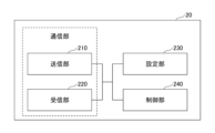
- FIG. 13 is a diagram illustrating an example of a functional configuration of a terminal; As shown in FIG. 13 , the terminal 20 has a transmitter 210 , a receiver 220 , a setter 230 and a controller 240 .
- the functional configuration shown in FIG. 13 is merely an example. As long as the operation according to the embodiment of the present invention can be executed, the functional division and the names of the functional units may be arbitrary.
- the transmitting unit 210 and the receiving unit 220 may be called a communication unit.
- the transmission unit 210 creates a transmission signal from the transmission data and wirelessly transmits the transmission signal.
- the receiving unit 220 wirelessly receives various signals and acquires a higher layer signal from the received physical layer signal. Also, the transmitting unit 210 transmits HARQ-ACK, and the receiving unit 220 receives the setting information and the like described in the embodiment.
- the setting unit 230 stores various types of setting information received from the base station 10 by the receiving unit 220 in the storage device, and reads them from the storage device as necessary.
- the setting unit 230 also stores preset setting information.
- the control unit 240 performs overall control of the terminal 20 including control related to signal transmission/reception. It should be noted that the functional unit related to signal transmission in control unit 240 may be included in transmitting unit 210 , and the functional unit related to signal reception in control unit 240 may be included in receiving unit 220 . Also, the transmitting section 210 and the receiving section 220 may be called a transmitter and a receiver, respectively.
- the terminal of this embodiment may be configured as a terminal shown in each section below. Also, the following communication methods may be implemented.
- the control unit controls to transmit the multiplexed information to the base station using the resource indicated by the last time or frequency indication information when there is a plurality of indication information corresponding to the multiplexed information. do, A terminal according to Clause 1 or Clause 2. (Section 4) The control unit controls to transmit the multiplexed information to the base station using a predetermined resource when there is no instruction information corresponding to the multiplexed information.
- the terminal according to any one of items 1 to 3.
- (Section 5) receiving information from a base station indicating which multiplex group to multiplex uplink information into; a step of multiplexing the uplink information for each multiplex group; and transmitting the multiplexed uplink information to the base station. The method of communication performed by the terminal.
- any of the above configurations provides a technology that facilitates implementation of terminals related to transmission of uplink information.
- multiplexing of uplink information can be realized regardless of the presence or absence of overlap.
- multiplexing of uplink information can be realized when there is a plurality of instruction information corresponding to multiplexed information.
- multiplexing of uplink information can be realized when there is no instruction information corresponding to the multiplexed information.
- each functional block may be implemented using one device that is physically or logically coupled, or directly or indirectly using two or more devices that are physically or logically separated (e.g. , wired, wireless, etc.) and may be implemented using these multiple devices.
- a functional block may be implemented by combining software in the one device or the plurality of devices.
- Functions include judging, determining, determining, calculating, calculating, processing, deriving, investigating, searching, checking, receiving, transmitting, outputting, accessing, resolving, selecting, choosing, establishing, comparing, assuming, expecting, assuming, Broadcasting, notifying, communicating, forwarding, configuring, reconfiguring, allocating, mapping, assigning, etc. can't
- a functional block (component) that performs transmission is called a transmitting unit or transmitter.
- the implementation method is not particularly limited.
- the base station 10, the terminal 20, etc. may function as a computer that performs processing of the wireless communication method of the present disclosure.
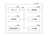
- FIG. 15 is a diagram illustrating an example of hardware configurations of the base station 10 and the terminal 20 according to an embodiment of the present disclosure.
- the base station 10 and terminal 20 described above are physically configured as a computer device including a processor 1001, a storage device 1002, an auxiliary storage device 1003, a communication device 1004, an input device 1005, an output device 1006, a bus 1007, and the like. good too.
- the term "apparatus” can be read as a circuit, device, unit, or the like.
- the hardware configuration of the base station 10 and terminal 20 may be configured to include one or more of each device shown in the figure, or may be configured without some devices.
- Each function of the base station 10 and the terminal 20 is performed by the processor 1001 performing calculations and controlling communication by the communication device 1004 by loading predetermined software (programs) onto hardware such as the processor 1001 and the storage device 1002. or by controlling at least one of data reading and writing in the storage device 1002 and the auxiliary storage device 1003 .
- the processor 1001 for example, operates an operating system and controls the entire computer.
- the processor 1001 may be configured with a central processing unit (CPU) including an interface with peripheral devices, a control device, an arithmetic device, registers, and the like.
- CPU central processing unit
- the control unit 140 , the control unit 240 and the like described above may be implemented by the processor 1001 .
- the processor 1001 reads programs (program codes), software modules, data, etc. from at least one of the auxiliary storage device 1003 and the communication device 1004 to the storage device 1002, and executes various processes according to them.
- programs program codes
- software modules software modules
- data etc.
- the program a program that causes a computer to execute at least part of the operations described in the above embodiments is used.
- control unit 140 of base station 10 shown in FIG. 12 may be implemented by a control program stored in storage device 1002 and operated by processor 1001 .
- the control unit 240 of the terminal 20 shown in FIG. 13 may be implemented by a control program stored in the storage device 1002 and operated by the processor 1001 .
- FIG. Processor 1001 may be implemented by one or more chips. Note that the program may be transmitted from a network via an electric communication line.
- the storage device 1002 is a computer-readable recording medium, for example, ROM (Read Only Memory), EPROM (Erasable Programmable ROM), EEPROM (Electrically Erasable Programmable ROM), RAM (Random Access Memory), etc. may be configured.
- the storage device 1002 may also be called a register, cache, main memory (main storage device), or the like.
- the storage device 1002 can store executable programs (program code), software modules, etc. for implementing a communication method according to an embodiment of the present disclosure.
- the auxiliary storage device 1003 is a computer-readable recording medium, for example, an optical disk such as a CD-ROM (Compact Disc ROM), a hard disk drive, a flexible disk, a magneto-optical disk (for example, a compact disk, a digital versatile disk, a Blu -ray disk), smart card, flash memory (eg, card, stick, key drive), floppy disk, magnetic strip, and/or the like.
- the storage medium described above may be, for example, a database, server, or other suitable medium including at least one of storage device 1002 and secondary storage device 1003 .
- the communication device 1004 is hardware (transmitting/receiving device) for communicating between computers via at least one of a wired network and a wireless network, and is also called a network device, a network controller, a network card, a communication module, or the like.
- the communication device 1004 includes a high-frequency switch, a duplexer, a filter, a frequency synthesizer, etc., in order to realize at least one of, for example, frequency division duplex (FDD) and time division duplex (TDD).
- FDD frequency division duplex
- TDD time division duplex
- the transceiver may be physically or logically separate implementations for the transmitter and receiver.
- the input device 1005 is an input device (for example, keyboard, mouse, microphone, switch, button, sensor, etc.) that receives input from the outside.
- the output device 1006 is an output device (for example, display, speaker, LED lamp, etc.) that outputs to the outside. Note that the input device 1005 and the output device 1006 may be integrated (for example, a touch panel).
- Each device such as the processor 1001 and the storage device 1002 is connected by a bus 1007 for communicating information.
- the bus 1007 may be configured using a single bus, or may be configured using different buses between devices.
- the base station 10 and the terminal 20 include hardware such as microprocessors, digital signal processors (DSPs), ASICs (Application Specific Integrated Circuits), PLDs (Programmable Logic Devices), and FPGAs (Field Programmable Gate Arrays). , and part or all of each functional block may be implemented by the hardware.
- processor 1001 may be implemented using at least one of these pieces of hardware.
- a vehicle 2001 includes a drive unit 2002, a steering unit 2003, an accelerator pedal 2004, a brake pedal 2005, a shift lever 2006, front wheels 2007, rear wheels 2008, an axle 2009, an electronic control unit 2010, and various sensors 2021 to 2029. , an information service unit 2012 and a communication module 2013 .
- a communication device mounted on vehicle 2001 may be applied to communication module 2013, for example.
- the driving unit 2002 is configured by, for example, an engine, a motor, or a hybrid of the engine and the motor.
- the steering unit 2003 includes at least a steering wheel (also referred to as steering wheel), and is configured to steer at least one of the front wheels and the rear wheels based on the operation of the steering wheel operated by the user.
- the electronic control unit 2010 is composed of a microprocessor 2031 , a memory (ROM, RAM) 2032 and a communication port (IO port) 2033 . Signals from various sensors 2021 to 2029 provided in the vehicle 2001 are input to the electronic control unit 2010 .
- the electronic control unit 2010 may also be called an ECU (Electronic Control Unit).
- the signals from the various sensors 2021 to 2029 include the current signal from the current sensor 2021 that senses the current of the motor, the rotation speed signal of the front and rear wheels acquired by the rotation speed sensor 2022, and the front wheel acquired by the air pressure sensor 2023. and rear wheel air pressure signal, vehicle speed signal obtained by vehicle speed sensor 2024, acceleration signal obtained by acceleration sensor 2025, accelerator pedal depression amount signal obtained by accelerator pedal sensor 2029, brake pedal sensor 2026 obtained by There are a brake pedal depression amount signal, a shift lever operation signal acquired by the shift lever sensor 2027, and a detection signal for detecting obstacles, vehicles, pedestrians, etc. acquired by the object detection sensor 2028, and the like.
- the information service unit 2012 includes various devices such as car navigation systems, audio systems, speakers, televisions, and radios for providing various types of information such as driving information, traffic information, and entertainment information, and one or more devices for controlling these devices. ECU.
- the information service unit 2012 uses information acquired from an external device via the communication module 2013 or the like to provide passengers of the vehicle 2001 with various multimedia information and multimedia services.
- Driving support system unit 2030 includes millimeter wave radar, LiDAR (Light Detection and Ranging), camera, positioning locator (e.g., GNSS, etc.), map information (e.g., high-definition (HD) map, automatic driving vehicle (AV) map, etc. ), gyro systems (e.g., IMU (Inertial Measurement Unit), INS (Inertial Navigation System), etc.), AI (Artificial Intelligence) chips, AI processors, etc., to prevent accidents and reduce the driver's driving load. and one or more ECUs for controlling these devices.
- the driving support system unit 2030 transmits and receives various information via the communication module 2013, and realizes a driving support function or an automatic driving function.
- the communication module 2013 can communicate with the microprocessor 2031 and components of the vehicle 2001 via communication ports.
- the communication module 2013 communicates with the vehicle 2001 through the communication port 2033, the drive unit 2002, the steering unit 2003, the accelerator pedal 2004, the brake pedal 2005, the shift lever 2006, the front wheels 2007, the rear wheels 2008, the axle 2009, the electronic Data is transmitted and received between the microprocessor 2031 and memory (ROM, RAM) 2032 in the control unit 2010 and the sensors 2021-29.
- the communication module 2013 is a communication device that can be controlled by the microprocessor 2031 of the electronic control unit 2010 and can communicate with an external device. For example, it transmits and receives various information to and from an external device via wireless communication.
- Communication module 2013 may be internal or external to electronic control unit 2010 .
- the external device may be, for example, a base station, a mobile station, or the like.
- the communication module 2013 transmits the current signal from the current sensor input to the electronic control unit 2010 to an external device via wireless communication.
- the communication module 2013 receives the rotation speed signal of the front and rear wheels obtained by the rotation speed sensor 2022, the air pressure signal of the front and rear wheels obtained by the air pressure sensor 2023, and the vehicle speed sensor. 2024, an acceleration signal obtained by an acceleration sensor 2025, an accelerator pedal depression amount signal obtained by an accelerator pedal sensor 2029, a brake pedal depression amount signal obtained by a brake pedal sensor 2026, and a shift lever.
- a shift lever operation signal obtained by the sensor 2027 and a detection signal for detecting obstacles, vehicles, pedestrians, etc. obtained by the object detection sensor 2028 are also transmitted to an external device via wireless communication.
- the communication module 2013 receives various information (traffic information, signal information, inter-vehicle information, etc.) transmitted from external devices, and displays it on the information service unit 2012 provided in the vehicle 2001 .
- Communication module 2013 also stores various information received from external devices in memory 2032 available to microprocessor 2031 .
- the microprocessor 2031 controls the drive unit 2002, the steering unit 2003, the accelerator pedal 2004, the brake pedal 2005, the shift lever 2006, the front wheels 2007, the rear wheels 2008, and the axle 2009 provided in the vehicle 2001.
- sensors 2021 to 2029 and the like may be controlled.
- the operations of a plurality of functional units may be physically performed by one component, or the operations of one functional unit may be physically performed by a plurality of components.
- the processing order may be changed as long as there is no contradiction.
- the base station 10 and the terminal 20 have been described using functional block diagrams for convenience of explanation of processing, such devices may be implemented in hardware, software, or a combination thereof.
- the software operated by the processor of the base station 10 according to the embodiment of the present invention and the software operated by the processor of the terminal 20 according to the embodiment of the present invention are stored in random access memory (RAM), flash memory, read-only memory, respectively. (ROM), EPROM, EEPROM, register, hard disk (HDD), removable disk, CD-ROM, database, server, or any other appropriate storage medium.
- notification of information is not limited to the aspects/embodiments described in the present disclosure, and may be performed using other methods.
- notification of information includes physical layer signaling (e.g., DCI (Downlink Control Information), UCI (Uplink Control Information)), higher layer signaling (e.g., RRC (Radio Resource Control) signaling, MAC (Medium Access Control) signaling, It may be implemented by broadcast information (MIB (Master Information Block), SIB (System Information Block)), other signals, or a combination thereof.
- RRC signaling may also be called an RRC message, for example, RRC It may be a connection setup (RRC Connection Setup) message, an RRC connection reconfiguration message, or the like.
- Each aspect/embodiment described in the present disclosure includes LTE (Long Term Evolution), LTE-A (LTE-Advanced), SUPER 3G, IMT-Advanced, 4G (4th generation mobile communication system), 5G (5th generation mobile communication system) system), 6th generation mobile communication system (6G), xth generation mobile communication system (xG) (xG (x is, for example, an integer, a decimal number)), FRA (Future Radio Access), NR (new Radio), New radio access ( NX), Future generation radio access (FX), W-CDMA (registered trademark), GSM (registered trademark), CDMA2000, UMB (Ultra Mobile Broadband), IEEE 802.11 (Wi-Fi (registered trademark)), IEEE 802 .16 (WiMAX (registered trademark)), IEEE 802.20, UWB (Ultra-WideBand), Bluetooth (registered trademark), and other suitable systems, and any extensions, modifications, creations, and provisions based on these systems. It may be applied to
- a specific operation performed by the base station 10 in this specification may be performed by its upper node in some cases.
- various operations performed for communication with terminal 20 may be performed by base station 10 and other network nodes other than base station 10 (eg, but not limited to MME or S-GW).
- base station 10 e.g, but not limited to MME or S-GW
- the other network node may be a combination of a plurality of other network nodes (for example, MME and S-GW).
- Information, signals, etc. described in the present disclosure may be output from a higher layer (or a lower layer) to a lower layer (or a higher layer). It may be input and output via multiple network nodes.
- Input/output information may be stored in a specific location (for example, memory) or managed using a management table. Input/output information and the like can be overwritten, updated, or appended. The output information and the like may be deleted. The entered information and the like may be transmitted to another device.
- the determination in the present disclosure may be performed by a value represented by 1 bit (0 or 1), may be performed by a boolean value (Boolean: true or false), or may be performed by comparing numerical values (e.g. , comparison with a predetermined value).
- Software whether referred to as software, firmware, middleware, microcode, hardware description language or otherwise, includes instructions, instruction sets, code, code segments, program code, programs, subprograms, and software modules. , applications, software applications, software packages, routines, subroutines, objects, executables, threads of execution, procedures, functions, and the like.
- software, instructions, information, etc. may be transmitted and received via a transmission medium.
- the software uses at least one of wired technology (coaxial cable, fiber optic cable, twisted pair, digital subscriber line (DSL), etc.) and wireless technology (infrared, microwave, etc.) to website, Wired and/or wireless technologies are included within the definition of transmission medium when sent from a server or other remote source.
- wired technology coaxial cable, fiber optic cable, twisted pair, digital subscriber line (DSL), etc.
- wireless technology infrared, microwave, etc.
- data, instructions, commands, information, signals, bits, symbols, chips, etc. may refer to voltages, currents, electromagnetic waves, magnetic fields or magnetic particles, light fields or photons, or any of these. may be represented by a combination of
- the channel and/or symbols may be signaling.
- a signal may also be a message.
- a component carrier may also be called a carrier frequency, a cell, a frequency carrier, or the like.
- system and “network” used in this disclosure are used interchangeably.
- information, parameters, etc. described in the present disclosure may be expressed using absolute values, may be expressed using relative values from a predetermined value, or may be expressed using other corresponding information.
- radio resources may be indexed.
- base station BS
- radio base station base station
- base station fixed station
- NodeB nodeB
- eNodeB eNodeB
- gNodeB gNodeB
- a base station can accommodate one or more (eg, three) cells.
- the overall coverage area of the base station can be partitioned into multiple smaller areas, each smaller area being associated with a base station subsystem (e.g., an indoor small base station (RRH:
- RRH indoor small base station
- the term "cell” or “sector” refers to part or all of the coverage area of at least one of the base stations and base station subsystems serving communication services in this coverage.
- MS Mobile Station
- UE User Equipment
- a mobile station is defined by those skilled in the art as a subscriber station, mobile unit, subscriber unit, wireless unit, remote unit, mobile device, wireless device, wireless communication device, remote device, mobile subscriber station, access terminal, mobile terminal, wireless It may also be called a terminal, remote terminal, handset, user agent, mobile client, client, or some other suitable term.
- At least one of the base station and mobile station may be called a transmitting device, a receiving device, a communication device, or the like.
- At least one of the base station and the mobile station may be a device mounted on a mobile object, the mobile object itself, or the like.
- the mobile object may be a vehicle (e.g., car, airplane, etc.), an unmanned mobile object (e.g., drone, self-driving car, etc.), or a robot (manned or unmanned ).
- at least one of the base station and the mobile station includes devices that do not necessarily move during communication operations.
- at least one of the base station and mobile station may be an IoT (Internet of Things) device such as a sensor.
- IoT Internet of Things
- the base station in the present disclosure may be read as a user terminal.
- communication between a base station and a user terminal is replaced with communication between a plurality of terminals 20 (for example, D2D (Device-to-Device), V2X (Vehicle-to-Everything), etc.)
- the terminal 20 may have the functions of the base station 10 described above.
- words such as "up” and “down” may be replaced with words corresponding to inter-terminal communication (for example, "side”).
- uplink channels, downlink channels, etc. may be read as side channels.
- user terminals in the present disclosure may be read as base stations.
- the base station may have the functions that the above-described user terminal has.
- determining and “determining” used in this disclosure may encompass a wide variety of actions.
- “Judgement” and “determination” are, for example, judging, calculating, computing, processing, deriving, investigating, looking up, searching, inquiring (eg, lookup in a table, database, or other data structure), ascertaining as “judged” or “determined”, and the like.
- "judgment” and “determination” are used for receiving (e.g., receiving information), transmitting (e.g., transmitting information), input, output, access (accessing) (for example, accessing data in memory) may include deeming that a "judgment” or “decision” has been made.
- judgment and “decision” are considered to be “judgment” and “decision” by resolving, selecting, choosing, establishing, comparing, etc. can contain.
- judgment and “decision” may include considering that some action is “judgment” and “decision”.
- judgment (decision) may be read as “assuming”, “expecting”, “considering”, or the like.
- connection means any direct or indirect connection or coupling between two or more elements, It can include the presence of one or more intermediate elements between two elements being “connected” or “coupled.” Couplings or connections between elements may be physical, logical, or a combination thereof. For example, “connection” may be read as "access”.
- two elements are defined using at least one of one or more wires, cables, and printed electrical connections and, as some non-limiting and non-exhaustive examples, in the radio frequency domain. , electromagnetic energy having wavelengths in the microwave and optical (both visible and invisible) regions, and the like.
- the reference signal can also be abbreviated as RS (Reference Signal), and may also be called Pilot depending on the applicable standard.
- RS Reference Signal
- any reference to elements using the "first,” “second,” etc. designations used in this disclosure does not generally limit the quantity or order of those elements. These designations may be used in this disclosure as a convenient method of distinguishing between two or more elements. Thus, reference to a first and second element does not imply that only two elements can be employed or that the first element must precede the second element in any way.
- a radio frame may consist of one or more frames in the time domain. Each frame or frames in the time domain may be referred to as a subframe. A subframe may also consist of one or more slots in the time domain. A subframe may be of a fixed length of time (eg, 1 ms) independent of numerology.
- a numerology may be a communication parameter that applies to the transmission and/or reception of a signal or channel. Numerology, for example, subcarrier spacing (SCS), bandwidth, symbol length, cyclic prefix length, transmission time interval (TTI), number of symbols per TTI, radio frame configuration, transceiver It may indicate at least one of certain filtering operations performed in the frequency domain, certain windowing operations performed by the transceiver in the time domain, and/or the like.
- SCS subcarrier spacing
- TTI transmission time interval
- transceiver It may indicate at least one of certain filtering operations performed in the frequency domain, certain windowing operations performed by the transceiver in the time domain, and/or the like.
- a slot may consist of one or more symbols (OFDM (Orthogonal Frequency Division Multiplexing) symbol, SC-FDMA (Single Carrier Frequency Division Multiple Access) symbol, etc.) in the time domain.
- a slot may be a unit of time based on numerology.
- a slot may contain multiple mini-slots. Each minislot may consist of one or more symbols in the time domain. A minislot may also be referred to as a subslot. A minislot may consist of fewer symbols than a slot.
- PDSCH (or PUSCH) transmitted in time units larger than minislots may be referred to as PDSCH (or PUSCH) mapping type A.
- PDSCH (or PUSCH) transmitted using minislots may be referred to as PDSCH (or PUSCH) mapping type B.
- Radio frames, subframes, slots, minislots and symbols all represent time units when transmitting signals. Radio frames, subframes, slots, minislots and symbols may be referred to by other corresponding designations.
- one subframe may be called a Transmission Time Interval (TTI)
- TTI Transmission Time Interval
- TTI Transmission Time Interval
- TTI Transmission Time Interval
- one slot or one minislot may be called a TTI.
- TTI Transmission Time Interval
- at least one of the subframe and TTI may be a subframe (1 ms) in existing LTE, a period shorter than 1 ms (eg, 1-13 symbols), or a period longer than 1 ms may be Note that the unit representing the TTI may be called a slot, mini-slot, or the like instead of a subframe.
- TTI refers to, for example, the minimum scheduling time unit in wireless communication.
- the base station performs scheduling to allocate radio resources (frequency bandwidth, transmission power, etc. that can be used by each terminal 20) to each terminal 20 on a TTI basis.
- radio resources frequency bandwidth, transmission power, etc. that can be used by each terminal 20
- TTI is not limited to this.
- a TTI may be a transmission time unit such as a channel-encoded data packet (transport block), code block, or codeword, or may be a processing unit such as scheduling and link adaptation. Note that when a TTI is given, the time interval (for example, the number of symbols) in which transport blocks, code blocks, codewords, etc. are actually mapped may be shorter than the TTI.
- one or more TTIs may be the minimum scheduling time unit. Also, the number of slots (the number of mini-slots) constituting the minimum time unit of the scheduling may be controlled.
- a TTI having a time length of 1 ms may be called a normal TTI (TTI in LTE Rel. 8-12), normal TTI, long TTI, normal subframe, normal subframe, long subframe, slot, or the like.
- a TTI that is shorter than a normal TTI may be called a shortened TTI, a short TTI, a partial or fractional TTI, a shortened subframe, a short subframe, a minislot, a subslot, a slot, and the like.
- the long TTI (e.g., normal TTI, subframe, etc.) may be replaced with a TTI having a time length exceeding 1 ms
- the short TTI e.g., shortened TTI, etc.
- a TTI having the above TTI length may be read instead.
- a resource block is a resource allocation unit in the time domain and the frequency domain, and may include one or more consecutive subcarriers in the frequency domain.
- the number of subcarriers included in the RB may be the same regardless of the numerology, and may be 12, for example.
- the number of subcarriers included in an RB may be determined based on numerology.
- the time domain of an RB may include one or more symbols and may be 1 slot, 1 minislot, 1 subframe, or 1 TTI long.
- One TTI, one subframe, etc. may each consist of one or more resource blocks.
- One or more RBs are physical resource blocks (PRBs), sub-carrier groups (SCGs), resource element groups (REGs), PRB pairs, RB pairs, etc. may be called.
- PRBs physical resource blocks
- SCGs sub-carrier groups
- REGs resource element groups
- PRB pairs RB pairs, etc. may be called.
- a resource block may be composed of one or more resource elements (RE: Resource Element).
- RE Resource Element
- 1 RE may be a radio resource region of 1 subcarrier and 1 symbol.
- a bandwidth part (which may also be called a bandwidth part) may represent a subset of contiguous common resource blocks (RBs) for a certain numerology on a certain carrier.
- the common RB may be identified by an RB index based on the common reference point of the carrier.
- PRBs may be defined in a BWP and numbered within that BWP.
- the BWP may include a BWP for UL (UL BWP) and a BWP for DL (DL BWP).
- UL BWP UL BWP
- DL BWP DL BWP
- One or more BWPs may be configured for terminal 20 within one carrier.
- At least one of the configured BWPs may be active, and the terminal 20 may not expect to transmit or receive a given signal/channel outside the active BWP.
- “cell”, “carrier”, etc. in the present disclosure may be read as "BWP”.
- radio frames, subframes, slots, minislots and symbols described above are only examples.
- the number of subframes contained in a radio frame the number of slots per subframe or radio frame, the number of minislots contained within a slot, the number of symbols and RBs contained in a slot or minislot, the number of Configurations such as the number of subcarriers, the number of symbols in a TTI, the symbol length, the cyclic prefix (CP) length, etc.
- CP cyclic prefix
- a and B are different may mean “A and B are different from each other.”
- the term may also mean that "A and B are different from C”.
- Terms such as “separate,” “coupled,” etc. may also be interpreted in the same manner as “different.”
- notification of predetermined information is not limited to being performed explicitly, but may be performed implicitly (for example, not notifying the predetermined information). good too.
Landscapes
- Engineering & Computer Science (AREA)
- Computer Networks & Wireless Communication (AREA)
- Signal Processing (AREA)
- Mobile Radio Communication Systems (AREA)
Abstract
Un terminal selon la présente invention comprend une unité de réception qui reçoit des informations indiquant si des informations de liaison montante provenant d'une station de base doivent être multiplexées avec n'importe quel groupe multiplex, une unité de commande qui multiplexe les informations de liaison montante pour chaque groupe multiplexé, et une unité de transmission qui transmet les informations de liaison montante multiplexées à la station de base.
Priority Applications (1)
| Application Number | Priority Date | Filing Date | Title |
|---|---|---|---|
| PCT/JP2021/039927 WO2023073898A1 (fr) | 2021-10-28 | 2021-10-28 | Terminal et procédé de communication |
Applications Claiming Priority (1)
| Application Number | Priority Date | Filing Date | Title |
|---|---|---|---|
| PCT/JP2021/039927 WO2023073898A1 (fr) | 2021-10-28 | 2021-10-28 | Terminal et procédé de communication |
Publications (1)
| Publication Number | Publication Date |
|---|---|
| WO2023073898A1 true WO2023073898A1 (fr) | 2023-05-04 |
Family
ID=86157588
Family Applications (1)
| Application Number | Title | Priority Date | Filing Date |
|---|---|---|---|
| PCT/JP2021/039927 WO2023073898A1 (fr) | 2021-10-28 | 2021-10-28 | Terminal et procédé de communication |
Country Status (1)
| Country | Link |
|---|---|
| WO (1) | WO2023073898A1 (fr) |
Citations (1)
| Publication number | Priority date | Publication date | Assignee | Title |
|---|---|---|---|---|
| JP2018507606A (ja) * | 2015-01-16 | 2018-03-15 | クゥアルコム・インコーポレイテッドQualcomm Incorporated | 拡張キャリアアグリゲーションに関するチャネル状態情報 |
-
2021
- 2021-10-28 WO PCT/JP2021/039927 patent/WO2023073898A1/fr unknown
Patent Citations (1)
| Publication number | Priority date | Publication date | Assignee | Title |
|---|---|---|---|---|
| JP2018507606A (ja) * | 2015-01-16 | 2018-03-15 | クゥアルコム・インコーポレイテッドQualcomm Incorporated | 拡張キャリアアグリゲーションに関するチャネル状態情報 |
Non-Patent Citations (1)
| Title |
|---|
| WILUS INC.: "On UCI enhancement for NR URLLC", 3GPP DRAFT; R1-1905431_UCI_FINAL, 3RD GENERATION PARTNERSHIP PROJECT (3GPP), MOBILE COMPETENCE CENTRE ; 650, ROUTE DES LUCIOLES ; F-06921 SOPHIA-ANTIPOLIS CEDEX ; FRANCE, vol. RAN WG1, no. Xi’an, China; 20190408 - 20190412, 3 April 2019 (2019-04-03), Mobile Competence Centre ; 650, route des Lucioles ; F-06921 Sophia-Antipolis Cedex ; France , XP051707501 * |
Similar Documents
| Publication | Publication Date | Title |
|---|---|---|
| WO2023073898A1 (fr) | Terminal et procédé de communication | |
| WO2023073899A1 (fr) | Terminal et procédé de communication | |
| WO2023073896A1 (fr) | Terminal et procédé de communication | |
| WO2023073897A1 (fr) | Terminal et procédé de communication | |
| WO2023021886A1 (fr) | Station de base, terminal et procédé de communication | |
| WO2023084659A1 (fr) | Terminal et procédé de communication | |
| WO2023089793A1 (fr) | Terminal, station de base et procédé de communication | |
| WO2023199447A1 (fr) | Terminal, station de base et procédé de communication | |
| WO2023089794A1 (fr) | Terminal, station de base et procédé de communication | |
| WO2023144976A1 (fr) | Terminal, station de base et procédé de communication | |
| WO2023085021A1 (fr) | Terminal et procédé de communication | |
| WO2023089792A1 (fr) | Terminal, station de base, et procédé de communication | |
| WO2023022137A1 (fr) | Terminal et procédé de communication | |
| WO2023135654A1 (fr) | Terminal, station de base et procédé de communication | |
| WO2023053431A1 (fr) | Terminal et procédé de communication | |
| WO2023145034A1 (fr) | Terminal et procédé de communication | |
| WO2023145035A1 (fr) | Terminal et procédé de communication | |
| WO2023132084A1 (fr) | Terminal, station de base et procédé de communication | |
| WO2023073964A1 (fr) | Terminal et procédé de communication | |
| WO2023053417A1 (fr) | Terminal, station de base, et procédé de communication | |
| WO2023144975A1 (fr) | Terminal, station de base et procédé de communication | |
| WO2023145036A1 (fr) | Terminal, station de base et procédé de communication | |
| WO2023017592A1 (fr) | Terminal et procédé de communication | |
| WO2023148945A1 (fr) | Terminal, station de base et procédé de communication | |
| WO2023163019A1 (fr) | Terminal, station de base, système de communication sans fil et procédé de communication |
Legal Events
| Date | Code | Title | Description |
|---|---|---|---|
| 121 | Ep: the epo has been informed by wipo that ep was designated in this application |
Ref document number: 21962443 Country of ref document: EP Kind code of ref document: A1 |
|
| ENP | Entry into the national phase |
Ref document number: 2023556009 Country of ref document: JP Kind code of ref document: A |