WO2023068070A1 - 端末、無線通信方法及び基地局 - Google Patents
端末、無線通信方法及び基地局 Download PDFInfo
- Publication number
- WO2023068070A1 WO2023068070A1 PCT/JP2022/037540 JP2022037540W WO2023068070A1 WO 2023068070 A1 WO2023068070 A1 WO 2023068070A1 JP 2022037540 W JP2022037540 W JP 2022037540W WO 2023068070 A1 WO2023068070 A1 WO 2023068070A1
- Authority
- WO
- WIPO (PCT)
- Prior art keywords
- tci
- pucch
- pusch
- information
- transmission
- Prior art date
- Legal status (The legal status is an assumption and is not a legal conclusion. Google has not performed a legal analysis and makes no representation as to the accuracy of the status listed.)
- Ceased
Links
Images


Classifications
-
- H—ELECTRICITY
- H04—ELECTRIC COMMUNICATION TECHNIQUE
- H04W—WIRELESS COMMUNICATION NETWORKS
- H04W52/00—Power management, e.g. Transmission Power Control [TPC] or power classes
- H04W52/04—Transmission power control [TPC]
- H04W52/06—TPC algorithms
- H04W52/14—Separate analysis of uplink or downlink
- H04W52/146—Uplink power control
-
- H—ELECTRICITY
- H04—ELECTRIC COMMUNICATION TECHNIQUE
- H04B—TRANSMISSION
- H04B7/00—Radio transmission systems, i.e. using radiation field
- H04B7/02—Diversity systems; Multi-antenna system, i.e. transmission or reception using multiple antennas
- H04B7/04—Diversity systems; Multi-antenna system, i.e. transmission or reception using multiple antennas using two or more spaced independent antennas
- H04B7/06—Diversity systems; Multi-antenna system, i.e. transmission or reception using multiple antennas using two or more spaced independent antennas at the transmitting station
-
- H—ELECTRICITY
- H04—ELECTRIC COMMUNICATION TECHNIQUE
- H04B—TRANSMISSION
- H04B7/00—Radio transmission systems, i.e. using radiation field
- H04B7/02—Diversity systems; Multi-antenna system, i.e. transmission or reception using multiple antennas
- H04B7/04—Diversity systems; Multi-antenna system, i.e. transmission or reception using multiple antennas using two or more spaced independent antennas
- H04B7/08—Diversity systems; Multi-antenna system, i.e. transmission or reception using multiple antennas using two or more spaced independent antennas at the receiving station
-
- H—ELECTRICITY
- H04—ELECTRIC COMMUNICATION TECHNIQUE
- H04W—WIRELESS COMMUNICATION NETWORKS
- H04W52/00—Power management, e.g. Transmission Power Control [TPC] or power classes
- H04W52/04—Transmission power control [TPC]
- H04W52/06—TPC algorithms
- H04W52/14—Separate analysis of uplink or downlink
-
- H—ELECTRICITY
- H04—ELECTRIC COMMUNICATION TECHNIQUE
- H04W—WIRELESS COMMUNICATION NETWORKS
- H04W52/00—Power management, e.g. Transmission Power Control [TPC] or power classes
- H04W52/04—Transmission power control [TPC]
- H04W52/38—TPC being performed in particular situations
- H04W52/42—TPC being performed in particular situations in systems with time, space, frequency or polarisation diversity
Definitions
- the present disclosure relates to terminals, wireless communication methods, and base stations in next-generation mobile communication systems.
- LTE Long Term Evolution
- 3GPP Rel. 10-14 LTE-Advanced (3GPP Rel. 10-14) has been specified for the purpose of further increasing the capacity and sophistication of LTE (Third Generation Partnership Project (3GPP) Release (Rel.) 8, 9).
- LTE successor systems for example, 5th generation mobile communication system (5G), 5G+ (plus), 6th generation mobile communication system (6G), New Radio (NR), 3GPP Rel. 15 and later
- 5G 5th generation mobile communication system
- 5G+ 5th generation mobile communication system
- 6G 6th generation mobile communication system
- NR New Radio
- UE User Equipment
- QCL assumption/Transmission Configuration Indication It has been considered to control transmission and reception processes based on TCI (state/space relationship).
- TCI state The application of the set/activated/indicated TCI state to multiple types of signals (channel/RS) is under consideration.
- channel/RS the relationship between the TCI state and the power control parameters is not sufficiently studied. If the determination method is not appropriate, there is a risk of causing deterioration in communication quality, throughput, and the like.
- one object of the present disclosure is to provide a terminal, a wireless communication method, and a base station that appropriately determine power control parameters.
- a terminal includes information about one or more transmission configuration indication (TCI) states for multiple types of signals, and one or more power control parameters for uplink transmission among the multiple types of signals. settings, and a controller that determines the power control parameters based on the one or more settings.
- TCI transmission configuration indication
- power control parameters can be determined appropriately.
- FIG. 1A and 1B show an example of a unified/common TCI framework.
- Figures 2A and 2B show an example of an indication of the association between TCI states and P0/alpha/closed-loop index settings.
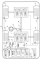
- FIG. 3 is a diagram illustrating an example of a schematic configuration of a radio communication system according to an embodiment.
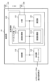
- FIG. 4 is a diagram illustrating an example of the configuration of a base station according to one embodiment.
- FIG. 5 is a diagram illustrating an example of the configuration of a user terminal according to one embodiment.
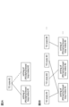
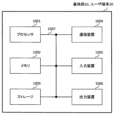
- FIG. 6 is a diagram illustrating an example of hardware configurations of a base station and a user terminal according to one embodiment.
- FIG. 7 is a diagram illustrating an example of a vehicle according to one embodiment;
- the reception processing e.g., reception, demapping, demodulation, decoding
- transmission processing e.g, at least one of transmission, mapping, precoding, modulation, encoding
- the TCI state may represent those that apply to downlink signals/channels.
- the equivalent of TCI conditions applied to uplink signals/channels may be expressed as spatial relations.
- the TCI state is information about the pseudo-colocation (QCL) of signals/channels, and may be called spatial reception parameters, spatial relation information, or the like.
- the TCI state may be set in the UE on a channel-by-channel or signal-by-signal basis.
- QCL is an index that indicates the statistical properties of a signal/channel. For example, when one signal/channel and another signal/channel have a QCL relationship, Doppler shift, Doppler spread, average delay ), delay spread, spatial parameters (e.g., spatial Rx parameter) are identical (QCL with respect to at least one of these). You may
- the spatial reception parameters may correspond to the reception beams of the UE (eg, reception analog beams), and the beams may be specified based on the spatial QCL.
- QCL or at least one element of QCL in the present disclosure may be read as sQCL (spatial QCL).
- QCL types may be defined for the QCL.
- QCL types AD may be provided with different parameters (or parameter sets) that can be assumed to be the same, and the parameters (which may be called QCL parameters) are shown below: QCL type A (QCL-A): Doppler shift, Doppler spread, mean delay and delay spread, QCL type B (QCL-B): Doppler shift and Doppler spread, QCL type C (QCL-C): Doppler shift and mean delay; • QCL Type D (QCL-D): Spatial reception parameters.
- CORESET Control Resource Set
- QCL QCL type D
- a UE may determine at least one of a transmit beam (Tx beam) and a receive beam (Rx beam) for a signal/channel based on the TCI conditions or QCL assumptions of that signal/channel.
- Tx beam transmit beam
- Rx beam receive beam
- the TCI state may be, for example, information about the QCL between the channel of interest (in other words, the reference signal (RS) for the channel) and another signal (for example, another RS). .
- the TCI state may be set (indicated) by higher layer signaling, physical layer signaling or a combination thereof.
- Physical layer signaling may be, for example, downlink control information (DCI).
- DCI downlink control information
- Channels for which TCI states or spatial relationships are set are, for example, Physical Downlink Shared Channel (PDSCH), Physical Downlink Control Channel (PDCCH), Physical Uplink Shared Channel It may be at least one of a channel (PUSCH)) and an uplink control channel (Physical Uplink Control Channel (PUCCH)).
- PDSCH Physical Downlink Shared Channel
- PDCCH Physical Uplink Control Channel
- RSs that have a QCL relationship with the channel are, for example, a synchronization signal block (SSB), a channel state information reference signal (CSI-RS), a measurement reference signal (Sounding It may be at least one of a reference signal (SRS)), a tracking CSI-RS (also called a tracking reference signal (TRS)), and a QCL detection reference signal (also called a QRS).
- SSB synchronization signal block
- CSI-RS channel state information reference signal
- Sounding It may be at least one of a reference signal (SRS)), a tracking CSI-RS (also called a tracking reference signal (TRS)), and a QCL detection reference signal (also called a QRS).
- SRS reference signal
- TRS tracking reference signal
- QRS QCL detection reference signal
- An SSB is a signal block that includes at least one of a Primary Synchronization Signal (PSS), a Secondary Synchronization Signal (SSS), and a Physical Broadcast Channel (PBCH).
- PSS Primary Synchronization Signal
- SSS Secondary Synchronization Signal
- PBCH Physical Broadcast Channel
- An SSB may also be called an SS/PBCH block.
- a QCL type X RS in a TCI state may mean an RS that has a QCL type X relationship with (the DMRS of) a certain channel/signal, and this RS is called a QCL type X QCL source in that TCI state.
- the unified TCI framework allows UL and DL channels to be controlled by a common framework.
- the unified TCI framework is Rel. Instead of defining TCI conditions or spatial relationships per channel as in 15, a common beam (common TCI condition) may be indicated and applied to all channels in the UL and DL, or for the UL A common beam may be applied to all channels in the UL and a common beam for the DL may be applied to all channels in the DL.
- One common beam for both DL and UL, or a common beam for DL and a common beam for UL (two common beams in total) are being considered.
- the UE may assume the same TCI state (joint TCI state, joint TCI pool, joint common TCI pool, joint TCI state set) for UL and DL.
- the UE assumes different TCI states for each of UL and DL (separate TCI state, separate TCI pool, UL separate TCI pool and DL separate TCI pool, separate common TCI pool, UL common TCI pool and DL common TCI pool).
- the UL and DL default beams may be aligned by MAC CE-based beam management (MAC CE level beam designation).
- the PDSCH default TCI state may be updated to match the default UL beam (spatial relationship).
- DCI-based beam management may indicate common beam/unified TCI state from the same TCI pool for both UL and DL (joint common TCI pool, joint TCI pool, set).
- X (>1) TCI states may be activated by MAC CE.
- the UL/DL DCI may select 1 out of X active TCI states.
- the selected TCI state may apply to both UL and DL channels/RS.
- the TCI pool (set) may be a plurality of TCI states set by RRC parameters, or a plurality of TCI states activated by MAC CE (active TCI state, active TCI pool, set).
- Each TCI state may be a QCL type A/D RS.
- SSB, CSI-RS, or SRS may be set as QCL type A/D RS.
- the number of TCI states corresponding to each of one or more TRPs may be defined. For example, the number N ( ⁇ 1) of TCI states (UL TCI states) applied to UL channels/RSs and the number M ( ⁇ 1) of TCI states (DL TCI states) applied to DL channels/RSs and may be defined. At least one of N and M may be signaled/configured/indicated to the UE via higher layer signaling/physical layer signaling.
- the UE has X UL and DL common TCI states (corresponding to X TRPs) (joint TCI status) is signaled/set/indicated.
- the UE is notified/configured/instructed of a TCI state common to multiple (two) UL and DL for multiple (two) TRPs (joint TCI state for multiple TRPs).
- multiple (two) UL TCI states and multiple (two) DL TCI states for multiple (two) TRPs State may mean signaled/set/indicated (separate TCI state for multiple TRPs).
- N and M are 1 or 2
- N and M may be 3 or more, and N and M may be different.
- RRC parameters configure multiple TCI states for both DL and UL.
- the MAC CE may activate multiple TCI states out of multiple configured TCI states.
- a DCI may indicate one of multiple TCI states that have been activated.
- DCI may be UL/DL DCI.
- the indicated TCI conditions may apply to at least one (or all) of the UL/DL channels/RSs.
- One DCI may indicate both UL TCI and DL TCI.
- one point may be one TCI state that applies to both UL and DL, or two TCI states that apply to UL and DL respectively.
- At least one of the multiple TCI states set by the RRC parameters and the multiple TCI states activated by the MAC CE may be called a TCI pool (common TCI pool, joint TCI pool, TCI state pool). good.
- Multiple TCI states activated by a MAC CE may be called an active TCI pool (active common TCI pool).
- RRC parameters higher layer parameters that configure multiple TCI states
- configuration information that configures multiple TCI states, or simply "configuration information.”
- to indicate one of the plurality of TCI states using the DCI may be receiving indication information indicating one of the plurality of TCI states included in the DCI. , it may simply be to receive "instruction information”.
- the RRC parameters configure multiple TCI states (joint common TCI pools) for both DL and UL.
- the MAC CE may activate multiple TCI states (active TCI pool) out of multiple configured TCI states. Separate active TCI pools for each of the UL and DL may be configured/activated.
- a DL DCI or a new DCI format may select (indicate) one or more (eg, one) TCI states.
- the selected TCI state may be applied to one or more (or all) DL channels/RS.
- the DL channel may be PDCCH/PDSCH/CSI-RS.
- the UE uses Rel.
- a 16 TCI state operation (TCI framework) may be used to determine the TCI state for each channel/RS in the DL.
- a UL DCI or new DCI format may select (indicate) one or more (eg, one) TCI states.
- the selected TCI state may be applied to one or more (or all) UL channels/RS.
- the UL channel may be PUSCH/SRS/PUCCH.
- different DCIs may indicate UL TCI and DL DCI separately.
- the existing DCI format 1_1/1_2 may be used to indicate common TCI status.
- a common TCI framework may have separate TCI states for DL and UL.
- TCI state pool may be read interchangeably.
- Transmission power control ⁇ PUSCH transmission power control>
- the transmission power of PUSCH is controlled based on the TPC command (also called value, increment/decrement value, correction value, etc.) indicated by the value of a field in DCI (also called TPC command field, etc.).
- a UE may use a parameter set (open-loop parameter set) with index j, index l in a power control adjustment state (PUSCH power control adjustment state) to activate an active UL on carrier f of serving cell c.
- PUSCH transmission power P PUSCH, b, f, c (i, j, q d , l)
- i [dBm] is P CMAX,f,c(i) , PO_PUSCH,b,f,c (j), M PUSCH RB,b,f,c (i), ⁇ b,f,c (j)
- It may be based on at least one of PL b,f,c (q d ), ⁇ TF,b,f,c (i), f b,f,c (i,l).
- the power control adjustment state may also be called a closed loop (CL)-power control (PC) state, a value based on the TPC command of the power control adjustment state index l, an accumulated value of the TPC commands, or a closed loop value.
- l may be called the closed-loop index.
- the PUSCH transmission opportunity i is a period during which the PUSCH is transmitted, and may be composed of, for example, one or more symbols, one or more slots, or the like.
- P CMAX,f,c(i) is, for example, the user terminal transmission power (also referred to as maximum transmission power, UE maximum output power, etc.) configured for carrier f of serving cell c at transmission opportunity i.
- P O_PUSCH,b,f,c (j) is, for example, a parameter related to the target received power set for active UL BWP b of carrier f of serving cell c at transmission opportunity i (eg, a parameter related to transmit power offset, transmission (Also referred to as power offset P0, target received power parameter, etc.).
- PO_UE_PUSCH,b,f,c (j) may be the sum of PO_NOMINAL_PUSCH,f,c (j) and PO_UE_PUSCH,b,f,c (j).
- M PUSCH RB,b,f,c (i) is, for example, the number of resource blocks (bandwidth) allocated to PUSCH for transmission opportunity i in active UL BWP b of serving cell c and carrier f with subcarrier spacing ⁇ .
- ⁇ b,f,c (j) are values provided by higher layer parameters (eg, msg3-Alpha, p0-PUSCH-Alpha, also called fractional factors, etc.).
- PL b, f, c (q d ) is, for example, a reference signal (RS) for downlink BWP associated with active UL BWP b of carrier f of serving cell c, pathloss reference RS, pathloss (PL)-RS , pathloss reference RS, pathloss measurement DL-RS, PUSCH-PathlossReferenceRS) is the pathloss (pathloss estimation [dB], pathloss compensation) calculated by the user terminal using the index qd .
- RS reference signal
- the UE uses a synchronization signal (SS) to obtain the Master Information Block (MIB).
- SS synchronization signal
- MIB Master Information Block
- PL b,f,c (q d ) may be calculated using the RS resources from the /physical broadcast channel (PBCH) block (SS block (SSB)).
- the set of RS resource indices may include one or both of a set of SS/PBCH block indices and a set of channel state information (CSI)-reference signal (RS) resource indices.
- the UE may identify the RS resource index q d within the set of RS resource indices.
- the UE may use the same RS resource index q d for the corresponding PRACH transmission.
- RAR Random Access Response
- a UE is provided with a PUSCH power control setting (e.g., SRI-PUSCH-PowerControl) by a sounding reference signal (SRS) resource indicator (SRI) and is provided with one or more values of pathloss reference RS IDs.
- SRS sounding reference signal
- SRI resource indicator
- the mapping between the set of values for the SRI field in DCI format 0_1 and the set of ID values of pathloss reference RSs is defined in higher layer signaling (e.g., sri-PUSCH in SRI-PUSCH-PowerControl -PowerControl-Id).
- the UE may determine the RS resource index qd from the ID of the pathloss reference RS mapped to the SRI field value in the DCI format 0_1 that schedules the PUSCH.
- the UE will The same RS resource index q d may be used for PUCCH transmissions in resources.
- the UE may use the RS resource index q d with a pathloss reference RS ID of zero.
- a configured grant configuration e.g. ConfiguredGrantConfig
- the RS resource index is determined by the pathloss reference index (e.g. pathlossReferenceIndex) in the specific parameter.
- q d may be provided to the UE.
- the UE For PUSCH transmission configured by the configuration grant configuration, if the configuration grant configuration does not contain a specific parameter, the UE selects the RS from the ID value of the pathloss reference RS mapped to the SRI field in the DCI format that activates the PUSCH transmission. A resource index qd may be determined. If the DCI format does not include the SRI field, the UE may determine the RS resource index q d with a pathloss reference RS ID of zero.
- ⁇ TF,b,f,c (i) is the transmission power adjustment component (offset, transmission format compensation) for UL BWP b of carrier f in serving cell c.
- f b,f,c (i,l) is the PUSCH power control adjustment state for active UL BWP b of carrier f in serving cell c at transmission opportunity i.
- f b,f,c (i,l) may be based on ⁇ PUSCH,b,f,c (i,l).
- f b,f,c (i,l) may be based on the accumulated values of ⁇ PUSCH,b,f,c (m,l).
- f b,f,c (i,l) may be ⁇ PUSCH,b,f,c (i,l) (absolute value).
- the UE sets the TPC command value to Accumulate and determine transmit power (apply TPC command value via accumulation) based on accumulation result (power control state).
- TPC-Accumulation When information indicating invalidity of TPC accumulation (TPC-Accumulation) is set (when information indicating invalidation of TPC accumulation is provided, when TPC accumulation is set to be invalid), the UE uses the TPC command Determine transmit power based on TPC command value (power control state) without accumulating values (apply TPC command value without accumulation).
- ⁇ PUSCH,b,f,c (i,l) is a TPC command value included in DCI format 0_0 or DCI format 0_1 that schedules PUSCH transmission opportunity i on active UL BWP b of carrier f of serving cell c, or a specific TPC command value encoded in conjunction with other TPC commands in DCI format 2_2 with CRC scrambled by a Radio Network Temporary Identifier (RNTI) (e.g., TPC-PUSCH-RNTI) of .
- RNTI Radio Network Temporary Identifier
- K PUSCH (i) is the serving cell after the last symbol of the corresponding PDCCH reception and before the first symbol of that PUSCH transmission.
- c may be the number of symbols in active UL BWP b for carrier f.
- K PUSCH (i) is the number of symbols per slot N symb slot in active UL BWP b of carrier f in serving cell c and PUSCH common configuration information It may be the number of K PUSCH,min symbols equal to the product of the minimum of the values provided by k2 in (PUSCH-ConfigCommon).
- the power control adjustment state may be set to have a plurality of states (for example, two states) or a single state depending on upper layer parameters. Also, if multiple power control adjustment states are configured, an index l (eg, l ⁇ 0,1 ⁇ ) may identify one of the multiple power control adjustment states.
- the transmission power of PUCCH is the TPC command (value, increment/decrement value, correction value, instruction value, etc.) indicated by the value of the field in DCI (also called TPC command field, first field, etc.). is controlled based on
- the PUCCH transmission opportunity for the active UL BWP b of the carrier f of the serving cell c (also known as the transmission period, etc.
- the transmission power of PUCCH at i) (P PUCCH, b, f, c (i, qu , qd , l)) [dBm] is P CMAX, f, c (i), PO_PUCCH, b, f , c (q u ), M PUCCH RB, b, f, c (i), PL b, f, c (q d ), ⁇ F_PUCCH (F), ⁇ TF, b, f, c (i), g may be based on at least one of b, f, c (i, l).
- the PUCCH transmission opportunity i is a period during which the PUCCH is transmitted, and may be composed of, for example, one or more symbols, one or more slots, or the like.
- P CMAX,f,c (i) is, for example, the user terminal transmission power (also referred to as maximum transmission power, UE maximum output power, etc.) configured for carrier f of serving cell c at transmission opportunity i.
- P O_PUCCH,b,f,c (q u ) is, for example, a parameter related to the target received power set for active UL BWP b of carrier f of serving cell c at transmission opportunity i (eg, a parameter related to transmit power offset, (also referred to as a transmission power offset P0 or a target reception power parameter, etc.).
- M PUCCH RB,b,f,c (i) is, for example, the number of resource blocks (bandwidth) allocated to PUCCH for transmission opportunity i in active UL BWP b of serving cell c and carrier f with subcarrier spacing ⁇ .
- PL b,f,c (q d ) is, for example, a reference signal for downlink BWP associated with active UL BWP b of carrier f of serving cell c (pathloss reference RS, pathloss(PL)-RS, pathloss reference RS, pathloss (pathloss estimation [dB], pathloss compensation) calculated by the user terminal using the index qd of pathloss measurement DL-RS, PUCCH-PathlossReferenceRS).
- the UE uses RS resources obtained from the SS/PBCH block used to obtain the MIB. to calculate the pathloss PL b,f,c (q d ).
- pathlossReferenceRSs in PUCCH power control information (PUCCH-PowerControl)
- PUCCH spatial relationship information (PUCCH-SpatialRelationInfo)
- the UE is provided with pathloss reference RS information for PUCCH
- This reference signal resource is either on the same serving cell or on the serving cell indicated by the value of pathlossReferenceLinking, if given.
- the pathloss reference association information indicates which DL the UE applies as a pathloss reference, a special cell (SpCell) or a secondary cell (SCell) corresponding to this UL.
- a SpCell may be a primary cell (PCell) in a master cell group (MCG) or a primary secondary cell (PSCell) in a secondary cell group (SCG).
- Pathloss reference RS information indicates a set of reference signals (eg, CSI-RS configuration or SS/PBCH block) used for PUCCH pathloss estimation.
- ⁇ F_PUCCH (F) is an upper layer parameter given for each PUCCH format.
- ⁇ TF,b,f,c (i) is the transmission power adjustment component (offset) for UL BWP b for carrier f in serving cell c.
- g b,f,c (i,l) is the value based on the TPC command of the power control adjustment state index l of the active UL BWP of carrier f for serving cell c and transmission opportunity i (e.g., power control adjustment state, TPC command accumulated value, closed-loop value, PUCCH power adjustment state).
- transmission opportunity i e.g., power control adjustment state, TPC command accumulated value, closed-loop value, PUCCH power adjustment state.
- g b,f,c (i,l) may be based on ⁇ PUCCH,b,f,c (i,l).
- g b,f,c (i,l) may be based on the accumulated value of ⁇ PUCCH,b,f,c (i,l).
- g b,f,c (i,l) may be ⁇ PUCCH,b,f,c (i,l) (absolute value).
- ⁇ PUCCH,b,f,c (i,l) is the TPC command value, DCI format 1_0 or DCI format detected by the UE in PUCCH transmission opportunity i of active UL BWP b on carrier f in serving cell c 1_1, or may be encoded in combination with other TPC commands in DCI format 2_2 with a CRC scrambled by a specific Radio Network Temporary Identifier (RNTI) (e.g., TPC-PUSCH-RNTI).
- RNTI Radio Network Temporary Identifier
- C(Ci) ⁇ 1 ⁇ PUCCH,b,f,c (m,l) is the sum of the TPC command values in the set C i of TPC command values with cardinality
- C(C i ) may be
- C i is the number of K PUCCH (ii 0 ) ⁇ 1 symbols before PUCCH transmission opportunity ii 0 and PUSCH transmission opportunity i for active UL BWP b on carrier f in serving cell c, for PUCCH power control adjustment state l.
- i 0 may be the smallest positive integer such that K PUCCH (ii 0 ) symbols before PUSCH transmission opportunity ii 0 are earlier than K PUCCH (i) symbols before PUSCH transmission opportunity i.
- K PUCCH (i) is after the last symbol of the corresponding PDCCH reception and before the first symbol of that PUCCH transmission. , the number of symbols in the active UL BWP b for carrier f in serving cell c.
- PUCCH transmission is configured by configured grant configuration information (ConfiguredGrantConfig)
- K PUSCH (i) is the number of symbols per slot N symb slot in active UL BWP b of carrier f in serving cell c
- PUSCH common configuration information It may be the number of K PUCCH,min symbols equal to the product of the minimum of the values provided by k2 in (PUSCH-ConfigCommon).
- twoPUCCH-PC-AdjustmentStates twoPUCCH-PC-AdjustmentStates
- PUCCH spatial relationship information PUCCH spatial relationship information
- the UE uses the P0 ID for PUCCH (p0-Set in PUCCH-PowerControl in PUCCH-Config
- the index provided by p0-PUCCH-Id in p0-PUCCH-Id) may yield a mapping between PUCCH Spatial Relation Information ID (pucch-SpatialRelationInfoId) values and closed loop indices (closedLoopIndex, power regulation state index l).
- the UE may determine the value of the closed loop index that provides the value of l through the link to the corresponding PUCCH P0 ID. .
- the UE may, based on the PUCCH spatial relationship information associated with the PUCCH P0 ID corresponding to q u and the closed-loop index value corresponding to l, q The value of l may be determined from the value of u .
- q u may be a PUCCH P0 ID (p0-PUCCH-Id) indicating a PUCCH P0 (P0-PUCCH) in a PUCCH P0 set (p0-Set).
- the UE shall set the PUCCH P0-ID (p0-PUCCH-Id) in the P0 set (p0-Set) equal to the minimum value of the PUCCH P0-ID (p0-PUCCH-Id).
- the P0 value for PUCCH (p0-PUCCH-Value) is obtained from the ID value.
- pathlossReferenceRSs pathloss reference RSs
- PUCCH pathlossReferenceRSs PUCCH pathloss reference RSs
- PUCCH pathlossReferenceRS-Id the value of the reference signal (referenceSignal) in the PUCCH pathloss reference RS is obtained.
- the available RS resources are on the primary cell or, if pathlossReferenceLinking is provided, on the serving cell indicated by the value of pathlossReferenceLinking.
- PUCCH power control adjustment state (closed loop ) index l 0 if the UE is not provided with the number of PUCCH power control adjustment states maintained by the UE being 2 or PUCCH spatial relationship information.
- P0, PL-RS, closed-loop indices are determined according to the rules.
- the PUCCH power control information element includes a P0 set (p0-Set), which is a set of P0 for PUCCH (P0-PUCCH), and a PUCCH path loss reference RS (PUCCH-PathlossReferenceRS). and pathlossReferenceRSs, which are a set of .
- the PUCCH P0 includes a PUCCH P0-ID (P0-PUCCH-Id) and a PUCCH P0 value (p0-PUCCH-Value).
- the PUCCH pathloss reference RS includes a PUCCH pathloss reference RS-ID (PUCCH-PathlossReferenceRS-Id) and a reference signal (referenceSignal, SSB index or NZP-CSI-RS resource ID).
- PUCCH pathloss reference RS-ID PUCCH pathloss reference RS-ID
- reference signal reference Signal
- ⁇ SRS transmission power control> For example, using the power control adjustment state index l, the transmission of the SRS on the SRS transmission occasion (also referred to as the transmission period, etc.) i for the active UL BWP b of the carrier f of the serving cell c.
- Power (P SRS, b, f, c (i, q s , l)) is P CMAX, f, c (i), P O_SRS, b, f, c (q s ), M SRS, b, f , c (i), ⁇ SRS, b, f, c (q s ), PL b, f, c (q d ), h b, f, c (i, l), good.
- the SRS transmission opportunity i is a period during which the SRS is transmitted, and may be composed of, for example, one or more symbols, one or more slots, or the like.
- P CMAX,f,c (i) is, eg, the UE maximum output power for carrier f of serving cell c at SRS transmission opportunity i.
- P O_SRS,b,f,c (q s ) is provided by p0 for active UL BWP b of carrier f in serving cell c and SRS resource set q s (provided by SRS-ResourceSet and SRS-ResourceSetId) is a parameter related to the target received power (for example, a parameter related to transmission power offset, a transmission power offset P0, or a target received power parameter, etc.).
- M SRS,b,f,c (i) is the SRS bandwidth in number of resource blocks for SRS transmission opportunity i on active UL BWP b for serving cell c and carrier f with subcarrier spacing ⁇ .
- ⁇ SRS,b,f,c (q s ) is provided by ⁇ (eg, alpha) for active UL BWP b of serving cell c and carrier f with subcarrier spacing ⁇ and SRS resource set q s .
- PL b,f,c (q d ) is the DL pathloss estimate [dB] calculated by the UE with RS resource index q d for the active DL BWP of serving cell c and SRS resource set q s ] (pathloss estimation [dB], pathloss compensation).
- RS resource index q d is the pathloss reference RS (provided by RS for pathloss reference, pathloss(PL)-RS, DL-RS for pathloss measurement, e.g., pathlossReferenceRS) associated with SRS resource set q s , SS/PBCH block index (eg, ssb-Index) or CSI-RS resource index (eg, csi-RS-Index).
- the UE uses RS resources obtained from the SS/PBCH block used to obtain the MIB. to calculate PL b,f,c (q d ).
- h b,f,c (i,l) is the SRS power control adjustment state for the active UL BWP of carrier f of serving cell c at SRS transmission opportunity i. Current PUSCH power control adjustment state f b,f,c (i,l ).
- the SRS power control adjustment state setting indicates independent power control adjustment states for SRS and PUSCH transmissions, then the SRS power control adjustment state h b,f,c (i) is ⁇ SRS,b, It may be based on f, c (m).
- h b,f,c (i) may be based on the accumulated values of ⁇ SRS,b,f,c (m).
- h b,f,c (i) may be ⁇ SRS,b,f,c (i) (absolute value).
- ⁇ SRS,b,f,c (m) may be a TPC command value that is encoded in PDCCH with DCI (eg, DCI format 2_3) in combination with other TPC commands.
- i 0 is the smallest positive integer such that K SRS (i ⁇ i 0 ) ⁇ 1 symbols before SRS transmission opportunity i ⁇ i 0 is earlier than K SRS (i) symbols before SRS transmission opportunity i may be
- K SRS (i) is the number after the last symbol of the corresponding PDCCH that triggers that SRS transmission and before the first symbol of that SRS transmission. , the number of symbols in the active UL BWP b for carrier f in serving cell c. If the SRS transmission is semi-persistent or periodic, K SRS (i) is the number of symbols per slot N symb slot in active UL BWP b on carrier f in serving cell c. , the number of K SRS,min symbols equal to the product of the minimum of the values provided by k2 in the PUSCH common configuration information (PUSCH-ConfigCommon).
- the pathloss reference signal (PL-RS / transmission power control (TPC) parameters)
- the pathloss reference signal (PL-RS) (configured for pathloss calculation) is included in the UL TCI state or the joint TCI state (if applicable), or It is considered to be associated with a UL TCI state or (if applicable) a joint TCI state. This association may be set/indicated by the RRC IE/MAC CE.
- the P0/alpha/closed-loop index settings can be associated with the UL or (if applicable) joint TCI state per BWP. In this case, multiple settings are set. Each setting can be associated with at least one TCI state. For a given TCI state, only one setting for PUSCH and only one setting for PUCCH are associated at a given time. For each PUSCH and PUCCH, each activated UL or joint TCI state (if applicable) is associated with one of multiple settings. If there is no such association for PUSCH and PUCCH respectively, the per channel/signal, per BWP, P0/alpha/closed-loop index setting is independent of the UL or joint TCI state.
- the P0/alpha/closed-loop index settings can be associated with the UL or (if applicable) the TCI state of the joint for each BWP. If there is no such association for SRS, then per BWP setting of P0/alpha/closed-loop index for SRS is independent of the UL or (if applicable) joint TCI state. This is useful for determining spatial relationships in Rel. Only available for SRS sets using 17 TCI states.
- the setting of the TPC parameters (P0/alpha/closed-loop index) excluding PL-RS for PUSCH/PUCCH/SRS can be set via the RRC IE for each UL TCI state or ( associated with the joint TCI state), if applicable.
- Multiple settings of P0/alpha/closed-loop indices for PUSCH/PUCCH/SRS are associated with per-BWP UL TCI states or joint TCI states for each of PUSCH/PUCCH/SRS. It may be associated with each of the UL or joint TCI states in the BWP.
- the inventors came up with a method for determining TPC parameters.
- A/B and “at least one of A and B” may be read interchangeably. Also, in the present disclosure, “A/B/C” may mean “at least one of A, B and C.”
- activate, deactivate, indicate (or indicate), select, configure, update, determine, etc. may be read interchangeably.
- supporting, controlling, controllable, operating, capable of operating, etc. may be read interchangeably.
- Radio Resource Control RRC
- RRC parameters RRC parameters
- RRC messages higher layer parameters
- information elements IEs
- settings etc.
- MAC Control Element CE
- update command activation/deactivation command, etc.
- higher layer signaling may be, for example, Radio Resource Control (RRC) signaling, Medium Access Control (MAC) signaling, broadcast information, or a combination thereof.
- RRC Radio Resource Control
- MAC Medium Access Control
- MAC signaling may use, for example, MAC Control Element (MAC CE), MAC Protocol Data Unit (PDU), and the like.
- Broadcast information includes, for example, Master Information Block (MIB), System Information Block (SIB), Remaining Minimum System Information (RMSI), and other system information ( It may be Other System Information (OSI).
- MIB Master Information Block
- SIB System Information Block
- RMSI Remaining Minimum System Information
- OSI System Information
- the physical layer signaling may be, for example, downlink control information (DCI), uplink control information (UCI), or the like.
- DCI downlink control information
- UCI uplink control information
- indices, identifiers (ID), indicators, resource IDs, etc. may be read interchangeably.
- sequences, lists, sets, groups, groups, clusters, subsets, etc. may be read interchangeably.
- DMRS port group e.g., spatial relationship group, Code Division Multiplexing (CDM) group, reference signal group, CORESET group, Physical Uplink Control Channel (PUCCH) group, PUCCH resource group), resource (e.g., reference signal resource, SRS resource), resource set (for example, reference signal resource set), CORESET pool, downlink Transmission Configuration Indication state (TCI state) (DL TCI state), uplink TCI state (UL TCI state), unified TCI State (unified TCI state), common TCI state (common TCI state), Quasi-Co-Location (QCL), QCL assumption, etc. may be read interchangeably.
- TCI state downlink Transmission Configuration Indication state
- DL TCI state uplink TCI state
- UL TCI state uplink TCI state
- unified TCI State unified TCI state
- common TCI state common TCI state
- QCL Quasi-Co-Location
- common beam common TCI, common TCI state, unified TCI, unified TCI state, TCI state applicable to DL and UL, TCI state applicable to multiple (multiple types) of channels/RS, multiple types of TCI states applicable to channels/RSs, TCI states for multiple types of signals, TCI states for multiple types of channels/RSs, TCI states, unified TCI states, UL and DL TCI states for joint TCI indication, separate TCIs
- the UL-only TCI state for indication and the DL-only TCI state for separate TCI indication may be interchanged.
- multiple TCI states set by RRC multiple TCI states activated by MAC CE, pool, TCI state pool, active TCI state pool, common TCI state pool, joint TCI state pool, separate TCI state pool , a common TCI state pool for UL, a common TCI state pool for DL, a common TCI state pool configured/activated by RRC/MAC CE, and TCI state information may be read interchangeably.
- DL TCI, DL only TCI (DL only TCI), separate DL only TCI, DL common TCI, DL unified TCI, common TCI, and unified TCI may be read interchangeably.
- UL TCI, UL only TCI, separate UL only TCI, UL common TCI, UL unified TCI, common TCI, and unified TCI may be read interchangeably.
- the channel/RS to which the unified TCI is applied may be PDSCH/PDCCH/CSI-RS/PUSCH/PUCCH/SRS.
- BWP, CC (cell), and CC (cell)/BWP may be read interchangeably.
- information on one or more TCI states, TCI state setting, TCI state list, and TCI state pool may be read interchangeably.
- TPC parameters power control parameters
- UL PC parameters UL PC parameters
- P0/alpha/closed-loop indices P0/alpha/closed-loop indices
- power control parameters excluding PL-RS may be read interchangeably.
- unified TCI states may be referred to simply as TCI states.
- MAC CE may be transmitted for one of PUSCH, PUCCH and SRS, or may be transmitted for two or more of PUSCH, PUCCH and SRS.
- the setting of P0/alpha/closed-loop index may be indicated/updated by MAC CE.
- the closed loop index setting may be indicated/updated by MAC CE, and the P0/alpha setting may be indicated/set/updated by RRC IE and not indicated/updated by MAC CE.
- the P0/alpha/closed-loop index setting is associated with a TCI state; the P0/alpha/closed-loop index setting for a TCI state is set/indicated/updated; Setting/indicating/updating the setting of the alpha/closed-loop index may be read interchangeably.
- This embodiment relates to updating/setting the P0/alpha/closed-loop indices associated with UL TCI states or joint TCI states (if available).
- ⁇ Setting Method 1 For each PUCCH/PUSCH/SRS, per BWP, multiple settings of P0/alpha/closed-loop indices are associated with one UL TCI state or one joint TCI state (if available). (may be configured with one UL TCI state or one joint TCI state).
- MAC CE selects/indicates one setting of P0/alpha/closed loop index for UL TCI state or joint TCI state (if available) per BWP for PUCCH/PUSCH/SRS respectively You may
- P0/alpha/closed loop index settings #1 and #2 for one TCI state #1 are set by the RRC IE, and TCI state #1 and The association between setting #1 may be indicated by MAC CE.
- Multiple settings of P0/alpha/closed loop index may be configured for PUCCH/PUSCH/SRS.
- the association (setting) between the P0/alpha/closed-loop index setting and the UL TCI state or joint TCI state (if it is available) is for PUCCH/PUSCH/SRS, per BWP: May be indicated by MAC CE.
- P0/alpha/closed-loop index settings #1, #2, and #3 are configured by the RRC IE, and TCI states #1 and #3 and settings
- the association between TCI state #2 and setting #2, the association between TCI state #4 and setting #3 may be indicated by the MAC CE.
- the association between P0/alpha/closed-loop index settings and UL TCI states or joint TCI states can be indicated appropriately.
- This embodiment relates to the case where the correspondence between the TCI state and the P0/alpha/closed-loop index setting is set/indicated/updated by the RRC IE/MAC CE.
- the UE may reset the CL-PC state accumulation (may be set to 0).
- the reset condition may include at least one of conditions 1 to 3 below.
- Condition 1 may be that alpha or P0 for PUSCH/PUCCH/SRS is updated (by RRC IE/MAC CE). This condition is based on Rel. 15 may be the same conditions. This condition is that the association between the P0/alpha/closed-loop index settings for PUSCH/PUCCH/SRS and the UL TCI state or joint TCI state (if it is available) is made per BWP (RRC be updated by the IE/MAC CE). This condition may be read as that the setting of P0/alpha/closed loop index for PUSCH/PUCCH/SRS is set/updated (by RRC IE/MAC CE) for each BWP.
- Condition 2 may be that the UL TCI state or joint TCI state (if it is available) is updated/configured (by RRC IE/MAC CE).
- Condition 3 may be that the UL TCI state or joint TCI state (if it is available) is indicated (by RRC IE/MAC CE/DCI). For example, the UE may reset the CL-PC state accumulation when the unified TCI state is updated by DCI.
- PUSCH/PUCCH/SRS in this embodiment may be only PUSCH, may be at least one of PUSCH, PUCCH and SRS, or may be all of PUSCH, PUCCH and SRS. .
- the CL-PC state can be appropriately controlled.
- This embodiment relates to the case where the correspondence between TCI states and P0/alpha/closed-loop index settings is not set/indicated/updated by the RRC IE/MAC CE.
- the setting of P0/alpha/closed loop index independent of UL TCI state or joint TCI state is set/indicated by RRC IE/MAC CE (per BWP).
- the UE may reset the CL-PC state accumulation (may be set to 0).
- the reset condition may include at least one of conditions 1 to 3 below.
- Condition 2 may be that the UL TCI state or joint TCI state (if it is available) is updated/configured (by RRC IE/MAC CE).
- Condition 3 may be that the UL TCI state or joint TCI state (if it is available) is indicated (by RRC IE/MAC CE/DCI). For example, the UE may reset the CL-PC state accumulation when the unified TCI state is updated by DCI.
- PUSCH/PUCCH/SRS in this embodiment may be only PUSCH, may be at least one of PUSCH, PUCCH and SRS, or may be all of PUSCH, PUCCH and SRS. .
- the CL-PC state can be appropriately controlled.
- RRC IE Radio Resource Control IE
- a higher layer parameter may indicate whether to enable the feature.
- UE capabilities may indicate whether the UE supports the feature.
- a UE for which a higher layer parameter corresponding to that function is set may perform that function. It may be defined that "UEs for which upper layer parameters corresponding to the function are not set shall not perform the function (for example, according to Rel. 15/16)".
- a UE that has reported/transmitted a UE capability indicating that it supports that function may perform that function. It may be specified that "a UE that does not report UE capabilities indicating that it supports the feature shall not perform that feature (eg according to Rel. 15/16)".
- a UE may perform a function if it reports/transmits a UE capability indicating that it supports the function and the higher layer parameters corresponding to the function are configured. "If the UE does not report/transmit a UE capability indicating that it supports the function, or if the higher layer parameters corresponding to the function are not configured, the UE does not perform the function (e.g., Rel. 15/ 16) may be defined.
- Which embodiment/option/choice/function among the above multiple embodiments is used may be set by higher layer parameters, may be reported by the UE as UE capabilities, or may be specified in the specification. It may be specified or determined by reported UE capabilities and higher layer parameter settings.
- UE capabilities may indicate whether the UE supports at least one of the following functions.
- Unified TCI Framework UE capabilities may include the maximum number of configured TCI states per BWP/per CC/per band/per UE.
- UE capabilities may include the maximum number of active TCI states per BWP/per CC/per band/per UE. - One or both of the joint TCI state and the separate TCI state.
- the UE can implement the above functions while maintaining compatibility with existing specifications.
- wireless communication system A configuration of a wireless communication system according to an embodiment of the present disclosure will be described below.
- communication is performed using any one of the radio communication methods according to the above embodiments of the present disclosure or a combination thereof.
- FIG. 3 is a diagram showing an example of a schematic configuration of a wireless communication system according to one embodiment.
- the wireless communication system 1 may be a system that realizes communication using Long Term Evolution (LTE), 5th generation mobile communication system New Radio (5G NR), etc. specified by the Third Generation Partnership Project (3GPP). .
- LTE Long Term Evolution
- 5G NR 5th generation mobile communication system New Radio
- 3GPP Third Generation Partnership Project
- the wireless communication system 1 may also support dual connectivity between multiple Radio Access Technologies (RATs) (Multi-RAT Dual Connectivity (MR-DC)).
- RATs Radio Access Technologies
- MR-DC is dual connectivity between LTE (Evolved Universal Terrestrial Radio Access (E-UTRA)) and NR (E-UTRA-NR Dual Connectivity (EN-DC)), dual connectivity between NR and LTE (NR-E -UTRA Dual Connectivity (NE-DC)), etc.
- RATs Radio Access Technologies
- MR-DC is dual connectivity between LTE (Evolved Universal Terrestrial Radio Access (E-UTRA)) and NR (E-UTRA-NR Dual Connectivity (EN-DC)), dual connectivity between NR and LTE (NR-E -UTRA Dual Connectivity (NE-DC)), etc.
- LTE Evolved Universal Terrestrial Radio Access
- EN-DC E-UTRA-NR Dual Connectivity
- NE-DC NR-E -UTRA Dual Connectivity
- the LTE (E-UTRA) base station (eNB) is the master node (MN), and the NR base station (gNB) is the secondary node (SN).
- the NR base station (gNB) is the MN, and the LTE (E-UTRA) base station (eNB) is the SN.
- the wireless communication system 1 has dual connectivity between multiple base stations within the same RAT (for example, dual connectivity (NR-NR Dual Connectivity (NN-DC) in which both MN and SN are NR base stations (gNB) )) may be supported.
- dual connectivity NR-NR Dual Connectivity (NN-DC) in which both MN and SN are NR base stations (gNB)
- gNB NR base stations
- a wireless communication system 1 includes a base station 11 forming a macrocell C1 with a relatively wide coverage, and base stations 12 (12a-12c) arranged in the macrocell C1 and forming a small cell C2 narrower than the macrocell C1. You may prepare.
- a user terminal 20 may be located within at least one cell. The arrangement, number, etc. of each cell and user terminals 20 are not limited to the embodiment shown in the figure.
- the base stations 11 and 12 are collectively referred to as the base station 10 when not distinguished.
- the user terminal 20 may connect to at least one of the multiple base stations 10 .
- the user terminal 20 may utilize at least one of carrier aggregation (CA) using a plurality of component carriers (CC) and dual connectivity (DC).
- CA carrier aggregation
- CC component carriers
- DC dual connectivity
- Each CC may be included in at least one of the first frequency band (Frequency Range 1 (FR1)) and the second frequency band (Frequency Range 2 (FR2)).
- Macrocell C1 may be included in FR1, and small cell C2 may be included in FR2.
- FR1 may be a frequency band below 6 GHz (sub-6 GHz)
- FR2 may be a frequency band above 24 GHz (above-24 GHz). Note that the frequency bands and definitions of FR1 and FR2 are not limited to these, and for example, FR1 may correspond to a higher frequency band than FR2.
- the user terminal 20 may communicate using at least one of Time Division Duplex (TDD) and Frequency Division Duplex (FDD) in each CC.
- TDD Time Division Duplex
- FDD Frequency Division Duplex
- a plurality of base stations 10 may be connected by wire (for example, an optical fiber conforming to Common Public Radio Interface (CPRI), X2 interface, etc.) or wirelessly (for example, NR communication).
- wire for example, an optical fiber conforming to Common Public Radio Interface (CPRI), X2 interface, etc.
- NR communication for example, when NR communication is used as a backhaul between the base stations 11 and 12, the base station 11 corresponding to the upper station is an Integrated Access Backhaul (IAB) donor, and the base station 12 corresponding to the relay station (relay) is an IAB Also called a node.
- IAB Integrated Access Backhaul
- relay station relay station
- the base station 10 may be connected to the core network 30 directly or via another base station 10 .
- the core network 30 may include, for example, at least one of Evolved Packet Core (EPC), 5G Core Network (5GCN), Next Generation Core (NGC), and the like.
- EPC Evolved Packet Core
- 5GCN 5G Core Network
- NGC Next Generation Core
- the user terminal 20 may be a terminal compatible with at least one of communication schemes such as LTE, LTE-A, and 5G.
- a radio access scheme based on orthogonal frequency division multiplexing may be used.
- OFDM orthogonal frequency division multiplexing
- CP-OFDM Cyclic Prefix OFDM
- DFT-s-OFDM Discrete Fourier Transform Spread OFDM
- OFDMA Orthogonal Frequency Division Multiple Access
- SC-FDMA Single Carrier Frequency Division Multiple Access
- a radio access method may be called a waveform.
- other radio access schemes for example, other single-carrier transmission schemes and other multi-carrier transmission schemes
- the UL and DL radio access schemes may be used as the UL and DL radio access schemes.
- a downlink shared channel Physical Downlink Shared Channel (PDSCH)
- PDSCH Physical Downlink Shared Channel
- PBCH Physical Broadcast Channel
- PDCCH Physical Downlink Control Channel
- an uplink shared channel (PUSCH) shared by each user terminal 20 an uplink control channel (PUCCH), a random access channel (Physical Random Access Channel (PRACH)) or the like may be used.
- PUSCH uplink shared channel
- PUCCH uplink control channel
- PRACH Physical Random Access Channel
- User data, upper layer control information, System Information Block (SIB), etc. are transmitted by the PDSCH.
- User data, higher layer control information, and the like may be transmitted by PUSCH.
- a Master Information Block (MIB) may be transmitted by the PBCH.
- Lower layer control information may be transmitted by the PDCCH.
- the lower layer control information may include, for example, downlink control information (DCI) including scheduling information for at least one of PDSCH and PUSCH.
- DCI downlink control information
- the DCI that schedules PDSCH may be called DL assignment, DL DCI, etc.
- the DCI that schedules PUSCH may be called UL grant, UL DCI, etc.
- PDSCH may be replaced with DL data
- PUSCH may be replaced with UL data.
- a control resource set (CControl Resource SET (CORESET)) and a search space (search space) may be used for PDCCH detection.
- CORESET corresponds to a resource searching for DCI.
- the search space corresponds to the search area and search method of PDCCH candidates.
- a CORESET may be associated with one or more search spaces. The UE may monitor CORESETs associated with certain search spaces based on the search space settings.
- One search space may correspond to PDCCH candidates corresponding to one or more aggregation levels.
- One or more search spaces may be referred to as a search space set. Note that “search space”, “search space set”, “search space setting”, “search space set setting”, “CORESET”, “CORESET setting”, etc. in the present disclosure may be read interchangeably.
- PUCCH channel state information
- acknowledgment information for example, Hybrid Automatic Repeat reQuest ACKnowledgement (HARQ-ACK), ACK/NACK, etc.
- SR scheduling request
- a random access preamble for connection establishment with a cell may be transmitted by the PRACH.
- downlink, uplink, etc. may be expressed without adding "link”.
- various channels may be expressed without adding "Physical" to the head.
- synchronization signals SS
- downlink reference signals DL-RS
- the DL-RS includes a cell-specific reference signal (CRS), a channel state information reference signal (CSI-RS), a demodulation reference signal (DeModulation Reference Signal (DMRS)), Positioning Reference Signal (PRS)), Phase Tracking Reference Signal (PTRS)), etc.
- CRS cell-specific reference signal
- CSI-RS channel state information reference signal
- DMRS Demodulation reference signal
- PRS Positioning Reference Signal
- PTRS Phase Tracking Reference Signal
- the synchronization signal may be, for example, at least one of a Primary Synchronization Signal (PSS) and a Secondary Synchronization Signal (SSS).
- PSS Primary Synchronization Signal
- SSS Secondary Synchronization Signal
- a signal block including SS (PSS, SSS) and PBCH (and DMRS for PBCH) may be called SS/PBCH block, SS Block (SSB), and so on.
- SS, SSB, etc. may also be referred to as reference signals.
- DMRS may also be called a user terminal-specific reference signal (UE-specific reference signal).
- FIG. 4 is a diagram illustrating an example of the configuration of a base station according to one embodiment.
- the base station 10 comprises a control section 110 , a transmission/reception section 120 , a transmission/reception antenna 130 and a transmission line interface 140 .
- One or more of each of the control unit 110, the transmitting/receiving unit 120, the transmitting/receiving antenna 130, and the transmission line interface 140 may be provided.
- this example mainly shows the functional blocks that characterize the present embodiment, and it may be assumed that the base station 10 also has other functional blocks necessary for wireless communication. A part of the processing of each unit described below may be omitted.
- the control unit 110 controls the base station 10 as a whole.
- the control unit 110 can be configured from a controller, a control circuit, and the like, which are explained based on common recognition in the technical field according to the present disclosure.
- the control unit 110 may control signal generation, scheduling (eg, resource allocation, mapping), and the like.
- the control unit 110 may control transmission/reception, measurement, etc. using the transmission/reception unit 120 , the transmission/reception antenna 130 and the transmission line interface 140 .
- the control unit 110 may generate data to be transmitted as a signal, control information, a sequence, etc., and transfer them to the transmission/reception unit 120 .
- the control unit 110 may perform call processing (setup, release, etc.) of communication channels, state management of the base station 10, management of radio resources, and the like.
- the transmitting/receiving section 120 may include a baseband section 121 , a radio frequency (RF) section 122 and a measuring section 123 .
- the baseband section 121 may include a transmission processing section 1211 and a reception processing section 1212 .
- the transmitting/receiving unit 120 is configured from a transmitter/receiver, an RF circuit, a baseband circuit, a filter, a phase shifter, a measurement circuit, a transmitting/receiving circuit, etc., which are explained based on common recognition in the technical field according to the present disclosure. be able to.
- the transmission/reception unit 120 may be configured as an integrated transmission/reception unit, or may be configured from a transmission unit and a reception unit.
- the transmission section may be composed of the transmission processing section 1211 and the RF section 122 .
- the receiving section may be composed of a reception processing section 1212 , an RF section 122 and a measurement section 123 .
- the transmitting/receiving antenna 130 can be configured from an antenna described based on common recognition in the technical field related to the present disclosure, such as an array antenna.
- the transmitting/receiving unit 120 may transmit the above-described downlink channel, synchronization signal, downlink reference signal, and the like.
- the transmitting/receiving unit 120 may receive the above-described uplink channel, uplink reference signal, and the like.
- the transmitting/receiving unit 120 may form at least one of the transmission beam and the reception beam using digital beamforming (eg, precoding), analog beamforming (eg, phase rotation), or the like.
- digital beamforming eg, precoding
- analog beamforming eg, phase rotation
- the transmission/reception unit 120 (transmission processing unit 1211) performs Packet Data Convergence Protocol (PDCP) layer processing, Radio Link Control (RLC) layer processing (for example, RLC retransmission control), Medium Access Control (MAC) layer processing (for example, HARQ retransmission control), etc. may be performed to generate a bit string to be transmitted.
- PDCP Packet Data Convergence Protocol
- RLC Radio Link Control
- MAC Medium Access Control
- HARQ retransmission control for example, HARQ retransmission control
- the transmission/reception unit 120 (transmission processing unit 1211) performs channel coding (which may include error correction coding), modulation, mapping, filtering, and discrete Fourier transform (DFT) on the bit string to be transmitted. Processing (if necessary), Inverse Fast Fourier Transform (IFFT) processing, precoding, transmission processing such as digital-to-analog conversion may be performed, and the baseband signal may be output.
- channel coding which may include error correction coding
- modulation modulation
- mapping mapping
- filtering filtering
- DFT discrete Fourier transform
- DFT discrete Fourier transform
- the transmitting/receiving unit 120 may perform modulation to a radio frequency band, filter processing, amplification, and the like on the baseband signal, and may transmit the radio frequency band signal via the transmitting/receiving antenna 130. .
- the transmitting/receiving unit 120 may perform amplification, filtering, demodulation to a baseband signal, etc. on the radio frequency band signal received by the transmitting/receiving antenna 130.
- the transmission/reception unit 120 (reception processing unit 1212) performs analog-to-digital conversion, Fast Fourier transform (FFT) processing, and Inverse Discrete Fourier transform (IDFT) processing on the acquired baseband signal. )) processing (if necessary), filtering, demapping, demodulation, decoding (which may include error correction decoding), MAC layer processing, RLC layer processing and PDCP layer processing. User data and the like may be acquired.
- FFT Fast Fourier transform
- IDFT Inverse Discrete Fourier transform
- the transmitting/receiving unit 120 may measure the received signal.
- the measurement unit 123 may perform Radio Resource Management (RRM) measurement, Channel State Information (CSI) measurement, etc. based on the received signal.
- the measurement unit 123 measures received power (for example, Reference Signal Received Power (RSRP)), reception quality (for example, Reference Signal Received Quality (RSRQ), Signal to Interference plus Noise Ratio (SINR), Signal to Noise Ratio (SNR)) , signal strength (for example, Received Signal Strength Indicator (RSSI)), channel information (for example, CSI), and the like may be measured.
- RSRP Reference Signal Received Power
- RSSQ Reference Signal Received Quality
- SINR Signal to Noise Ratio
- RSSI Received Signal Strength Indicator
- channel information for example, CSI
- the transmission path interface 140 transmits and receives signals (backhaul signaling) to and from devices included in the core network 30, other base stations 10, etc., and user data (user plane data) for the user terminal 20, control plane data, and the like. Data and the like may be obtained, transmitted, and the like.
- the transmitter and receiver of the base station 10 in the present disclosure may be configured by at least one of the transmitter/receiver 120, the transmitter/receiver antenna 130, and the transmission path interface 140.
- the transmitting/receiving unit 120 transmits information on one or more transmission configuration indication (TCI) states for multiple types of signals, and one or more settings of power control parameters for uplink transmission among the multiple types of signals.
- TCI transmission configuration indication
- Controller 110 may determine the power control parameter based on the one or more settings.
- FIG. 5 is a diagram illustrating an example of the configuration of a user terminal according to one embodiment.
- the user terminal 20 includes a control section 210 , a transmission/reception section 220 and a transmission/reception antenna 230 .
- One or more of each of the control unit 210, the transmitting/receiving unit 220, and the transmitting/receiving antenna 230 may be provided.
- this example mainly shows the functional blocks of the features of the present embodiment, and it may be assumed that the user terminal 20 also has other functional blocks necessary for wireless communication. A part of the processing of each unit described below may be omitted.
- the control unit 210 controls the user terminal 20 as a whole.
- the control unit 210 can be configured from a controller, a control circuit, and the like, which are explained based on common recognition in the technical field according to the present disclosure.
- the control unit 210 may control signal generation, mapping, and the like.
- the control unit 210 may control transmission/reception, measurement, etc. using the transmission/reception unit 220 and the transmission/reception antenna 230 .
- the control unit 210 may generate data, control information, sequences, etc. to be transmitted as signals, and transfer them to the transmission/reception unit 220 .
- the transmitting/receiving section 220 may include a baseband section 221 , an RF section 222 and a measurement section 223 .
- the baseband section 221 may include a transmission processing section 2211 and a reception processing section 2212 .
- the transmitting/receiving unit 220 can be configured from a transmitter/receiver, an RF circuit, a baseband circuit, a filter, a phase shifter, a measurement circuit, a transmitting/receiving circuit, etc., which are explained based on common recognition in the technical field according to the present disclosure.
- the transmission/reception unit 220 may be configured as an integrated transmission/reception unit, or may be configured from a transmission unit and a reception unit.
- the transmission section may be composed of a transmission processing section 2211 and an RF section 222 .
- the receiving section may include a reception processing section 2212 , an RF section 222 and a measurement section 223 .
- the transmitting/receiving antenna 230 can be configured from an antenna described based on common recognition in the technical field related to the present disclosure, such as an array antenna.
- the transmitting/receiving unit 220 may receive the above-described downlink channel, synchronization signal, downlink reference signal, and the like.
- the transmitting/receiving unit 220 may transmit the above-described uplink channel, uplink reference signal, and the like.
- the transmitter/receiver 220 may form at least one of the transmission beam and the reception beam using digital beamforming (eg, precoding), analog beamforming (eg, phase rotation), or the like.
- digital beamforming eg, precoding
- analog beamforming eg, phase rotation
- the transmission/reception unit 220 (transmission processing unit 2211) performs PDCP layer processing, RLC layer processing (for example, RLC retransmission control), MAC layer processing (for example, for data and control information acquired from the control unit 210, for example , HARQ retransmission control), etc., to generate a bit string to be transmitted.
- RLC layer processing for example, RLC retransmission control
- MAC layer processing for example, for data and control information acquired from the control unit 210, for example , HARQ retransmission control
- the transmitting/receiving unit 220 (transmission processing unit 2211) performs channel coding (which may include error correction coding), modulation, mapping, filtering, DFT processing (if necessary), and IFFT processing on a bit string to be transmitted. , precoding, digital-analog conversion, and other transmission processing may be performed, and the baseband signal may be output.
- Whether or not to apply DFT processing may be based on transform precoding settings. Transmitting/receiving unit 220 (transmission processing unit 2211), for a certain channel (for example, PUSCH), if transform precoding is enabled, the above to transmit the channel using the DFT-s-OFDM waveform
- the DFT process may be performed as the transmission process, or otherwise the DFT process may not be performed as the transmission process.
- the transmitting/receiving unit 220 may perform modulation to a radio frequency band, filter processing, amplification, and the like on the baseband signal, and may transmit the radio frequency band signal via the transmitting/receiving antenna 230. .
- the transmitting/receiving section 220 may perform amplification, filtering, demodulation to a baseband signal, etc. on the radio frequency band signal received by the transmitting/receiving antenna 230.
- the transmission/reception unit 220 (reception processing unit 2212) performs analog-to-digital conversion, FFT processing, IDFT processing (if necessary), filtering, demapping, demodulation, decoding (error correction) on the acquired baseband signal. decoding), MAC layer processing, RLC layer processing, PDCP layer processing, and other reception processing may be applied to acquire user data and the like.
- the transmitting/receiving section 220 may measure the received signal.
- the measurement unit 223 may perform RRM measurement, CSI measurement, etc. based on the received signal.
- the measuring unit 223 may measure received power (eg, RSRP), received quality (eg, RSRQ, SINR, SNR), signal strength (eg, RSSI), channel information (eg, CSI), and the like.
- the measurement result may be output to control section 210 .
- the transmitter and receiver of the user terminal 20 in the present disclosure may be configured by at least one of the transmitter/receiver 220 and the transmitter/receiver antenna 230 .
- the transmitting/receiving unit 220 receives information on one or more transmission configuration indication (TCI) states for multiple types of signals, and one or more settings of power control parameters for uplink transmission among the multiple types of signals. You may Controller 210 may determine the power control parameter based on the one or more settings.
- TCI transmission configuration indication
- the transmitting/receiving unit 220 may receive a medium access control (MAC) control element (CE) indicating association between the one or more TCI states and the one or more settings.
- MAC medium access control
- CE control element
- the controller 210 may reset the accumulation of power control adjustment states.
- the controller 210 may reset the accumulation of power control adjustment states. .
- each functional block may be implemented using one device that is physically or logically coupled, or directly or indirectly using two or more devices that are physically or logically separated (e.g. , wired, wireless, etc.) and may be implemented using these multiple devices.
- a functional block may be implemented by combining software in the one device or the plurality of devices.
- function includes judgment, decision, determination, calculation, calculation, processing, derivation, investigation, search, confirmation, reception, transmission, output, access, resolution, selection, selection, establishment, comparison, assumption, expectation, deem , broadcasting, notifying, communicating, forwarding, configuring, reconfiguring, allocating, mapping, assigning, etc.
- a functional block (component) that performs transmission may be called a transmitting unit, a transmitter, or the like. In either case, as described above, the implementation method is not particularly limited.
- a base station, a user terminal, etc. in an embodiment of the present disclosure may function as a computer that performs processing of the wireless communication method of the present disclosure.
- FIG. 6 is a diagram illustrating an example of hardware configurations of a base station and a user terminal according to one embodiment.
- the base station 10 and user terminal 20 described above may be physically configured as a computer device including a processor 1001, a memory 1002, a storage 1003, a communication device 1004, an input device 1005, an output device 1006, a bus 1007, and the like. .
- the hardware configuration of the base station 10 and the user terminal 20 may be configured to include one or more of each device shown in the figure, or may be configured without some devices.
- processor 1001 may be implemented by one or more chips.
- predetermined software program
- the processor 1001 performs calculations, communication via the communication device 1004 and at least one of reading and writing data in the memory 1002 and the storage 1003 .
- the processor 1001 operates an operating system and controls the entire computer.
- the processor 1001 may be configured by a central processing unit (CPU) including an interface with peripheral devices, a control device, an arithmetic device, registers, and the like.
- CPU central processing unit
- control unit 110 210
- transmission/reception unit 120 220
- FIG. 10 FIG. 10
- the processor 1001 reads programs (program codes), software modules, data, etc. from at least one of the storage 1003 and the communication device 1004 to the memory 1002, and executes various processes according to them.
- programs program codes
- software modules software modules
- data etc.
- the control unit 110 (210) may be implemented by a control program stored in the memory 1002 and running on the processor 1001, and other functional blocks may be similarly implemented.
- the memory 1002 is a computer-readable recording medium, such as Read Only Memory (ROM), Erasable Programmable ROM (EPROM), Electrically EPROM (EEPROM), Random Access Memory (RAM), or at least any other suitable storage medium. may be configured by one.
- the memory 1002 may also be called a register, cache, main memory (main storage device), or the like.
- the memory 1002 can store executable programs (program code), software modules, etc. for implementing a wireless communication method according to an embodiment of the present disclosure.
- the storage 1003 is a computer-readable recording medium, for example, a flexible disk, a floppy (registered trademark) disk, a magneto-optical disk (for example, a compact disk (Compact Disc ROM (CD-ROM), etc.), a digital versatile disk, Blu-ray disc), removable disc, hard disk drive, smart card, flash memory device (e.g., card, stick, key drive), magnetic stripe, database, server, or other suitable storage medium may be configured by Storage 1003 may also be called an auxiliary storage device.
- a computer-readable recording medium for example, a flexible disk, a floppy (registered trademark) disk, a magneto-optical disk (for example, a compact disk (Compact Disc ROM (CD-ROM), etc.), a digital versatile disk, Blu-ray disc), removable disc, hard disk drive, smart card, flash memory device (e.g., card, stick, key drive), magnetic stripe, database, server, or other suitable storage medium may be configured by Storage 1003 may also
- the communication device 1004 is hardware (transmitting/receiving device) for communicating between computers via at least one of a wired network and a wireless network, and is also called a network device, a network controller, a network card, a communication module, or the like.
- the communication device 1004 includes a high-frequency switch, duplexer, filter, frequency synthesizer, etc. in order to realize at least one of frequency division duplex (FDD) and time division duplex (TDD), for example. may be configured to include
- the transmitting/receiving unit 120 (220), the transmitting/receiving antenna 130 (230), and the like described above may be realized by the communication device 1004.
- the transmitter/receiver 120 (220) may be physically or logically separated into a transmitter 120a (220a) and a receiver 120b (220b).
- the input device 1005 is an input device (for example, keyboard, mouse, microphone, switch, button, sensor, etc.) that receives input from the outside.
- the output device 1006 is an output device (for example, a display, a speaker, a Light Emitting Diode (LED) lamp, etc.) that outputs to the outside. Note that the input device 1005 and the output device 1006 may be integrated (for example, a touch panel).
- Each device such as the processor 1001 and the memory 1002 is connected by a bus 1007 for communicating information.
- the bus 1007 may be configured using a single bus, or may be configured using different buses between devices.
- the base station 10 and the user terminal 20 include a microprocessor, a digital signal processor (DSP), an application specific integrated circuit (ASIC), a programmable logic device (PLD), a field programmable gate array (FPGA), etc. It may be configured including hardware, and a part or all of each functional block may be realized using the hardware. For example, processor 1001 may be implemented using at least one of these pieces of hardware.
- DSP digital signal processor
- ASIC application specific integrated circuit
- PLD programmable logic device
- FPGA field programmable gate array
- a signal may also be a message.
- a reference signal may be abbreviated as RS, and may also be called a pilot, a pilot signal, etc., depending on the applicable standard.
- a component carrier may also be called a cell, a frequency carrier, a carrier frequency, or the like.
- a radio frame may consist of one or more periods (frames) in the time domain.
- Each of the one or more periods (frames) that make up a radio frame may be called a subframe.
- a subframe may consist of one or more slots in the time domain.
- a subframe may be a fixed time length (eg, 1 ms) independent of numerology.
- a numerology may be a communication parameter applied to at least one of transmission and reception of a certain signal or channel.
- Numerology for example, subcarrier spacing (SCS), bandwidth, symbol length, cyclic prefix length, transmission time interval (TTI), number of symbols per TTI, radio frame configuration , a particular filtering process performed by the transceiver in the frequency domain, a particular windowing process performed by the transceiver in the time domain, and/or the like.
- a slot may consist of one or more symbols (Orthogonal Frequency Division Multiplexing (OFDM) symbol, Single Carrier Frequency Division Multiple Access (SC-FDMA) symbol, etc.) in the time domain.
- OFDM Orthogonal Frequency Division Multiplexing
- SC-FDMA Single Carrier Frequency Division Multiple Access
- a slot may also be a unit of time based on numerology.
- a slot may contain multiple mini-slots. Each minislot may consist of one or more symbols in the time domain. A minislot may also be referred to as a subslot. A minislot may consist of fewer symbols than a slot.
- a PDSCH (or PUSCH) transmitted in time units larger than a minislot may be referred to as PDSCH (PUSCH) Mapping Type A.
- PDSCH (or PUSCH) transmitted using minislots may be referred to as PDSCH (PUSCH) mapping type B.
- Radio frames, subframes, slots, minislots and symbols all represent time units when transmitting signals. Radio frames, subframes, slots, minislots and symbols may be referred to by other corresponding designations. Note that time units such as frames, subframes, slots, minislots, and symbols in the present disclosure may be read interchangeably.
- one subframe may be called a TTI
- a plurality of consecutive subframes may be called a TTI
- one slot or one minislot may be called a TTI. That is, at least one of the subframe and TTI may be a subframe (1 ms) in existing LTE, a period shorter than 1 ms (eg, 1-13 symbols), or a period longer than 1 ms may be Note that the unit representing the TTI may be called a slot, mini-slot, or the like instead of a subframe.
- TTI refers to, for example, the minimum scheduling time unit in wireless communication.
- a base station performs scheduling to allocate radio resources (frequency bandwidth, transmission power, etc. that can be used by each user terminal) to each user terminal on a TTI basis.
- radio resources frequency bandwidth, transmission power, etc. that can be used by each user terminal
- a TTI may be a transmission time unit such as a channel-encoded data packet (transport block), code block, or codeword, or may be a processing unit such as scheduling and link adaptation. Note that when a TTI is given, the time interval (for example, the number of symbols) in which transport blocks, code blocks, codewords, etc. are actually mapped may be shorter than the TTI.
- one or more TTIs may be the minimum scheduling time unit. Also, the number of slots (the number of mini-slots) constituting the minimum time unit of the scheduling may be controlled.
- a TTI having a time length of 1 ms may be called a normal TTI (TTI in 3GPP Rel. 8-12), normal TTI, long TTI, normal subframe, normal subframe, long subframe, slot, or the like.
- a TTI that is shorter than a normal TTI may be called a shortened TTI, a short TTI, a partial or fractional TTI, a shortened subframe, a short subframe, a minislot, a subslot, a slot, and the like.
- the long TTI (e.g., normal TTI, subframe, etc.) may be replaced with a TTI having a time length exceeding 1 ms
- the short TTI e.g., shortened TTI, etc.
- a TTI having the above TTI length may be read instead.
- a resource block is a resource allocation unit in the time domain and frequency domain, and may include one or more consecutive subcarriers (subcarriers) in the frequency domain.
- the number of subcarriers included in the RB may be the same regardless of the neumerology, eg twelve.
- the number of subcarriers included in an RB may be determined based on neumerology.
- an RB may contain one or more symbols in the time domain and may be 1 slot, 1 minislot, 1 subframe or 1 TTI long.
- One TTI, one subframe, etc. may each be configured with one or more resource blocks.
- One or more RBs are Physical Resource Block (PRB), Sub-Carrier Group (SCG), Resource Element Group (REG), PRB pair, RB Also called a pair.
- PRB Physical Resource Block
- SCG Sub-Carrier Group
- REG Resource Element Group
- PRB pair RB Also called a pair.
- a resource block may be composed of one or more resource elements (Resource Element (RE)).
- RE resource elements
- 1 RE may be a radio resource region of 1 subcarrier and 1 symbol.
- a Bandwidth Part (which may also be called a bandwidth part) represents a subset of contiguous common resource blocks (RBs) for a numerology on a carrier.
- the common RB may be identified by an RB index based on the common reference point of the carrier.
- PRBs may be defined in a BWP and numbered within that BWP.
- BWP may include UL BWP (BWP for UL) and DL BWP (BWP for DL).
- BWP for UL
- BWP for DL DL BWP
- One or multiple BWPs may be configured for a UE within one carrier.
- At least one of the configured BWPs may be active, and the UE may not expect to transmit or receive a given signal/channel outside the active BWP.
- BWP bitmap
- radio frames, subframes, slots, minislots, symbols, etc. described above are merely examples.
- the number of subframes contained in a radio frame, the number of slots per subframe or radio frame, the number of minislots contained within a slot, the number of symbols and RBs contained in a slot or minislot, the number of Configurations such as the number of subcarriers and the number of symbols in a TTI, symbol length, cyclic prefix (CP) length, etc. can be varied.
- the information, parameters, etc. described in the present disclosure may be expressed using absolute values, may be expressed using relative values from a predetermined value, or may be expressed using other corresponding information. may be represented. For example, radio resources may be indicated by a predetermined index.
- data, instructions, commands, information, signals, bits, symbols, chips, etc. may refer to voltages, currents, electromagnetic waves, magnetic fields or magnetic particles, light fields or photons, or any of these. may be represented by a combination of
- information, signals, etc. can be output from a higher layer to a lower layer and/or from a lower layer to a higher layer.
- Information, signals, etc. may be input and output through multiple network nodes.
- Input/output information, signals, etc. may be stored in a specific location (for example, memory), or may be managed using a management table. Input and output information, signals, etc. may be overwritten, updated or appended. Output information, signals, etc. may be deleted. Input information, signals, etc. may be transmitted to other devices.
- Uplink Control Information (UCI) Uplink Control Information
- RRC Radio Resource Control
- MIB Master Information Block
- SIB System Information Block
- SIB System Information Block
- MAC Medium Access Control
- the physical layer signaling may also be called Layer 1/Layer 2 (L1/L2) control information (L1/L2 control signal), L1 control information (L1 control signal), and the like.
- RRC signaling may also be called an RRC message, and may be, for example, an RRC connection setup message, an RRC connection reconfiguration message, or the like.
- MAC signaling may be notified using, for example, a MAC Control Element (CE).
- CE MAC Control Element
- notification of predetermined information is not limited to explicit notification, but implicit notification (for example, by not notifying the predetermined information or by providing another information by notice of
- the determination may be made by a value (0 or 1) represented by 1 bit, or by a boolean value represented by true or false. , may be performed by numerical comparison (eg, comparison with a predetermined value).
- Software whether referred to as software, firmware, middleware, microcode, hardware description language or otherwise, includes instructions, instruction sets, code, code segments, program code, programs, subprograms, and software modules. , applications, software applications, software packages, routines, subroutines, objects, executables, threads of execution, procedures, functions, and the like.
- software, instructions, information, etc. may be transmitted and received via a transmission medium.
- the software uses wired technology (coaxial cable, fiber optic cable, twisted pair, Digital Subscriber Line (DSL), etc.) and/or wireless technology (infrared, microwave, etc.) , a server, or other remote source, these wired and/or wireless technologies are included within the definition of transmission media.
- a “network” may refer to devices (eg, base stations) included in a network.
- precoding "precoding weight”
- QCL Quality of Co-Location
- TCI state Transmission Configuration Indication state
- spatialal patial relation
- spatialal domain filter "transmission power”
- phase rotation "antenna port
- antenna port group "layer”
- number of layers Terms such as “rank”, “resource”, “resource set”, “resource group”, “beam”, “beam width”, “beam angle”, “antenna”, “antenna element”, “panel” are interchangeable. can be used as intended.
- base station BS
- radio base station fixed station
- NodeB NodeB
- eNB eNodeB
- gNB gNodeB
- Access point "Transmission Point (TP)”, “Reception Point (RP)”, “Transmission/Reception Point (TRP)”, “Panel”
- a base station may also be referred to by terms such as macrocell, small cell, femtocell, picocell, and the like.
- a base station can accommodate one or more (eg, three) cells.
- the overall coverage area of the base station can be partitioned into multiple smaller areas, and each smaller area is assigned to a base station subsystem (e.g., a small indoor base station (Remote Radio)). Head (RRH))) may also provide communication services.
- a base station subsystem e.g., a small indoor base station (Remote Radio)). Head (RRH)
- RRH Head
- the terms "cell” or “sector” refer to part or all of the coverage area of at least one of the base stations and base station subsystems that serve communication within such coverage.
- MS Mobile Station
- UE User Equipment
- Mobile stations include subscriber stations, mobile units, subscriber units, wireless units, remote units, mobile devices, wireless devices, wireless communication devices, remote devices, mobile subscriber stations, access terminals, mobile terminals, wireless terminals, remote terminals. , a handset, a user agent, a mobile client, a client, or some other suitable term.
- At least one of the base station and the mobile station may be called a transmitting device, a receiving device, a wireless communication device, or the like. At least one of the base station and the mobile station may be a device mounted on a moving object, the mobile itself, or the like.
- the moving body refers to a movable object, the speed of movement is arbitrary, and it naturally includes cases where the moving body is stationary.
- Examples of such moving bodies include vehicles, transportation vehicles, automobiles, motorcycles, bicycles, connected cars, excavators, bulldozers, wheel loaders, dump trucks, forklifts, trains, buses, carts, rickshaws, and ships (ships and other watercraft). , airplanes, rockets, satellites, drones, multi-copters, quad-copters, balloons and objects mounted on them.
- the mobile body may be a mobile body that autonomously travels based on an operation command.
- the mobile object may be a vehicle (e.g., car, airplane, etc.), an unmanned mobile object (e.g., drone, self-driving car, etc.), or a robot (manned or unmanned ).
- a vehicle e.g., car, airplane, etc.
- an unmanned mobile object e.g., drone, self-driving car, etc.
- a robot manned or unmanned .
- at least one of the base station and the mobile station includes devices that do not necessarily move during communication operations.
- at least one of the base station and mobile station may be an Internet of Things (IoT) device such as a sensor.
- IoT Internet of Things
- FIG. 7 is a diagram showing an example of a vehicle according to one embodiment.
- the vehicle 40 includes a drive unit 41, a steering unit 42, an accelerator pedal 43, a brake pedal 44, a shift lever 45, left and right front wheels 46, left and right rear wheels 47, an axle 48, an electronic control unit 49, various sensors (current sensor 50, revolution sensor 51, air pressure sensor 52, vehicle speed sensor 53, acceleration sensor 54, accelerator pedal sensor 55, brake pedal sensor 56, shift lever sensor 57, and object detection sensor 58), information service unit 59 and communication module 60.
- various sensors current sensor 50, revolution sensor 51, air pressure sensor 52, vehicle speed sensor 53, acceleration sensor 54, accelerator pedal sensor 55, brake pedal sensor 56, shift lever sensor 57, and object detection sensor 58
- information service unit 59 and communication module 60.
- the driving unit 41 is composed of, for example, at least one of an engine, a motor, and a hybrid of an engine and a motor.
- the steering unit 42 includes at least a steering wheel (also referred to as a steering wheel), and is configured to steer at least one of the front wheels 46 and the rear wheels 47 based on the operation of the steering wheel operated by the user.
- the electronic control unit 49 is composed of a microprocessor 61 , a memory (ROM, RAM) 62 , and a communication port (eg, input/output (IO) port) 63 . Signals from various sensors 50 to 58 provided in the vehicle are input to the electronic control unit 49 .
- the electronic control unit 49 may be called an Electronic Control Unit (ECU).
- ECU Electronic Control Unit
- the signals from the various sensors 50 to 58 include a current signal from the current sensor 50 that senses the current of the motor, a rotation speed signal of the front wheels 46/rear wheels 47 obtained by the rotation speed sensor 51, and an air pressure sensor 52.
- air pressure signal of front wheels 46/rear wheels 47 vehicle speed signal obtained by vehicle speed sensor 53, acceleration signal obtained by acceleration sensor 54, depression amount signal of accelerator pedal 43 obtained by accelerator pedal sensor 55, brake pedal sensor
- the information service unit 59 includes various devices such as car navigation systems, audio systems, speakers, displays, televisions, and radios for providing (outputting) various information such as driving information, traffic information, and entertainment information, and these devices. and one or more ECUs that control The information service unit 59 provides various information/services (for example, multimedia information/multimedia services) to the occupants of the vehicle 40 using information acquired from an external device via the communication module 60 or the like.
- various information/services for example, multimedia information/multimedia services
- the information service unit 59 may include an input device (e.g., keyboard, mouse, microphone, switch, button, sensor, touch panel, etc.) that receives input from the outside, and an output device that outputs to the outside (e.g., display, speaker, LED lamp, touch panel, etc.).
- an input device e.g., keyboard, mouse, microphone, switch, button, sensor, touch panel, etc.
- an output device e.g., display, speaker, LED lamp, touch panel, etc.
- the driving support system unit 64 includes millimeter wave radar, Light Detection and Ranging (LiDAR), camera, positioning locator (eg, Global Navigation Satellite System (GNSS), etc.), map information (eg, High Definition (HD)) maps, autonomous vehicle (AV) maps, etc.), gyro systems (e.g., inertial measurement units (IMU), inertial navigation systems (INS), etc.), artificial intelligence ( Artificial intelligence (AI) chips, AI processors, and other devices that provide functions to prevent accidents and reduce the driver's driving load, and one or more devices that control these devices ECU.
- the driving support system unit 64 transmits and receives various information via the communication module 60, and realizes a driving support function or an automatic driving function.
- the communication module 60 can communicate with the microprocessor 61 and components of the vehicle 40 via the communication port 63 .
- the communication module 60 communicates with the vehicle 40 through a communication port 63 such as a driving unit 41, a steering unit 42, an accelerator pedal 43, a brake pedal 44, a shift lever 45, left and right front wheels 46, left and right rear wheels 47, Data (information) is transmitted and received between the axle 48, the microprocessor 61 and memory (ROM, RAM) 62 in the electronic control unit 49, and various sensors 50-58.
- the communication module 60 is a communication device that can be controlled by the microprocessor 61 of the electronic control unit 49 and can communicate with an external device. For example, it transmits and receives various information to and from an external device via wireless communication.
- Communication module 60 may be internal or external to electronic control 49 .
- the external device may be, for example, the above-described base station 10, user terminal 20, or the like.
- the communication module 60 may be, for example, at least one of the base station 10 and the user terminal 20 described above (and may function as at least one of the base station 10 and the user terminal 20).
- the communication module 60 receives signals from the various sensors 50 to 58 described above input to the electronic control unit 49, information obtained based on the signals, and input from the outside (user) obtained via the information service unit 59. may be transmitted to the external device via wireless communication.
- the electronic control unit 49, the various sensors 50-58, the information service unit 59, etc. may be called an input unit that receives input.
- the PUSCH transmitted by communication module 60 may include information based on the above inputs.
- the communication module 60 receives various information (traffic information, signal information, inter-vehicle information, etc.) transmitted from an external device and displays it on the information service unit 59 provided in the vehicle.
- the information service unit 59 is an output unit that outputs information (for example, outputs information to devices such as displays and speakers based on the PDSCH received by the communication module 60 (or data/information decoded from the PDSCH)). may be called
- the communication module 60 stores various information received from an external device in a memory 62 that can be used by the microprocessor 61 . Based on the information stored in the memory 62, the microprocessor 61 controls the drive unit 41, the steering unit 42, the accelerator pedal 43, the brake pedal 44, the shift lever 45, the left and right front wheels 46, and the left and right rear wheels provided in the vehicle 40. 47, axle 48, and various sensors 50-58 may be controlled.
- the base station in the present disclosure may be read as a user terminal.
- communication between a base station and a user terminal is replaced with communication between multiple user terminals (for example, Device-to-Device (D2D), Vehicle-to-Everything (V2X), etc.)
- the user terminal 20 may have the functions of the base station 10 described above.
- words such as "uplink” and “downlink” may be replaced with words corresponding to communication between terminals (for example, "sidelink”).
- uplink channels, downlink channels, etc. may be read as sidelink channels.
- user terminals in the present disclosure may be read as base stations.
- the base station 10 may have the functions of the user terminal 20 described above.
- operations that are assumed to be performed by the base station may be performed by its upper node in some cases.
- various operations performed for communication with a terminal may involve the base station, one or more network nodes other than the base station (e.g., Clearly, this can be done by a Mobility Management Entity (MME), Serving-Gateway (S-GW), etc. (but not limited to these) or a combination thereof.
- MME Mobility Management Entity
- S-GW Serving-Gateway
- each aspect/embodiment described in the present disclosure may be used alone, may be used in combination, or may be used by switching along with execution. Also, the processing procedures, sequences, flowcharts, etc. of each aspect/embodiment described in the present disclosure may be rearranged as long as there is no contradiction. For example, the methods described in this disclosure present elements of the various steps using a sample order, and are not limited to the specific order presented.
- LTE Long Term Evolution
- LTE-A LTE-Advanced
- LTE-B LTE-Beyond
- SUPER 3G IMT-Advanced
- 4G 4th generation mobile communication system
- 5G 5th generation mobile communication system
- 6G 6th generation mobile communication system
- xG x is, for example, an integer or a decimal number
- Future Radio Access FAA
- RAT New-Radio Access Technology
- NR New Radio
- NX New radio access
- FX Future generation radio access
- GSM registered trademark
- CDMA2000 Code Division Multiple Access
- UMB Ultra Mobile Broadband
- IEEE 802 .11 Wi-Fi®
- IEEE 802.16 WiMAX®
- IEEE 802.20 Ultra-WideBand (UWB), Bluetooth®, or any other suitable wireless communication method. It may be applied to a system to be used, a next-generation system extended, modified, created or defined based on these.
- any reference to elements using the "first,” “second,” etc. designations used in this disclosure does not generally limit the quantity or order of those elements. These designations may be used in this disclosure as a convenient method of distinguishing between two or more elements. Thus, references to first and second elements do not imply that only two elements may be employed or that the first element must precede the second element in any way.
- determining includes judging, calculating, computing, processing, deriving, investigating, looking up, searching, inquiry ( For example, looking up in a table, database, or another data structure), ascertaining, etc. may be considered to be “determining.”
- determining (deciding) includes receiving (e.g., receiving information), transmitting (e.g., transmitting information), input, output, access ( accessing (e.g., accessing data in memory), etc.
- determining is considered to be “determining” resolving, selecting, choosing, establishing, comparing, etc. good too. That is, “determining (determining)” may be regarded as “determining (determining)” some action.
- Maximum transmit power described in this disclosure may mean the maximum value of transmit power, may mean the nominal maximum transmit power (the nominal UE maximum transmit power), or may mean the rated maximum transmit power (the rated UE maximum transmit power).
- connection refers to any connection or coupling, direct or indirect, between two or more elements. and can include the presence of one or more intermediate elements between two elements that are “connected” or “coupled” to each other. Couplings or connections between elements may be physical, logical, or a combination thereof. For example, "connection” may be read as "access”.
- radio frequency domain when two elements are connected, using one or more wires, cables, printed electrical connections, etc., and as some non-limiting and non-exhaustive examples, radio frequency domain, microwave They can be considered to be “connected” or “coupled” together using the domain, electromagnetic energy having wavelengths in the optical (both visible and invisible) domain, and the like.
- a and B are different may mean “A and B are different from each other.”
- the term may also mean that "A and B are different from C”.
- Terms such as “separate,” “coupled,” etc. may also be interpreted in the same manner as “different.”
Landscapes
- Engineering & Computer Science (AREA)
- Computer Networks & Wireless Communication (AREA)
- Signal Processing (AREA)
- Mobile Radio Communication Systems (AREA)
Priority Applications (3)
| Application Number | Priority Date | Filing Date | Title |
|---|---|---|---|
| JP2023554482A JPWO2023068070A1 (https=) | 2021-10-19 | 2022-10-07 | |
| US18/701,829 US20240430809A1 (en) | 2021-10-19 | 2022-10-07 | Terminal, radio communication method, and base station |
| CN202280084037.XA CN118451663A (zh) | 2021-10-19 | 2022-10-07 | 终端、无线通信方法以及基站 |
Applications Claiming Priority (2)
| Application Number | Priority Date | Filing Date | Title |
|---|---|---|---|
| JP2021171201 | 2021-10-19 | ||
| JP2021-171201 | 2021-10-19 |
Publications (1)
| Publication Number | Publication Date |
|---|---|
| WO2023068070A1 true WO2023068070A1 (ja) | 2023-04-27 |
Family
ID=86058091
Family Applications (1)
| Application Number | Title | Priority Date | Filing Date |
|---|---|---|---|
| PCT/JP2022/037540 Ceased WO2023068070A1 (ja) | 2021-10-19 | 2022-10-07 | 端末、無線通信方法及び基地局 |
Country Status (4)
| Country | Link |
|---|---|
| US (1) | US20240430809A1 (https=) |
| JP (1) | JPWO2023068070A1 (https=) |
| CN (1) | CN118451663A (https=) |
| WO (1) | WO2023068070A1 (https=) |
Cited By (3)
| Publication number | Priority date | Publication date | Assignee | Title |
|---|---|---|---|---|
| WO2025069223A1 (ja) * | 2023-09-26 | 2025-04-03 | 株式会社Nttドコモ | 端末、無線通信方法及び基地局 |
| WO2025069222A1 (ja) * | 2023-09-26 | 2025-04-03 | 株式会社Nttドコモ | 端末、無線通信方法及び基地局 |
| WO2025069224A1 (ja) * | 2023-09-26 | 2025-04-03 | 株式会社Nttドコモ | 端末、無線通信方法及び基地局 |
Citations (2)
| Publication number | Priority date | Publication date | Assignee | Title |
|---|---|---|---|---|
| WO2021064959A1 (ja) * | 2019-10-03 | 2021-04-08 | 株式会社Nttドコモ | 端末及び無線通信方法 |
| US20210219246A1 (en) * | 2020-01-15 | 2021-07-15 | Kai Xu | Power Control Procedure in a Wireless Network |
Family Cites Families (6)
| Publication number | Priority date | Publication date | Assignee | Title |
|---|---|---|---|---|
| US10149255B2 (en) * | 2015-05-01 | 2018-12-04 | Qualcomm Incorporated | Low latency uplink power control |
| WO2022086259A1 (en) * | 2020-10-22 | 2022-04-28 | Samsung Electronics Co., Ltd. | Method and apparatus for uplink data repetitive transmission and reception for network cooperative communication |
| US20250106781A1 (en) * | 2021-10-01 | 2025-03-27 | Qualcomm Incorporated | Power control configuration |
| US11974230B2 (en) * | 2022-01-05 | 2024-04-30 | Qualcomm Incorporated | Indicating uplink power control parameters |
| WO2024000302A1 (en) * | 2022-06-29 | 2024-01-04 | Nec Corporation | Method, device and computer readable medium of communication |
| US20240049330A1 (en) * | 2022-08-08 | 2024-02-08 | Comcast Cable Communications, Llc | Determination of Power Control Parameters |
-
2022
- 2022-10-07 JP JP2023554482A patent/JPWO2023068070A1/ja active Pending
- 2022-10-07 US US18/701,829 patent/US20240430809A1/en active Pending
- 2022-10-07 CN CN202280084037.XA patent/CN118451663A/zh active Pending
- 2022-10-07 WO PCT/JP2022/037540 patent/WO2023068070A1/ja not_active Ceased
Patent Citations (2)
| Publication number | Priority date | Publication date | Assignee | Title |
|---|---|---|---|---|
| WO2021064959A1 (ja) * | 2019-10-03 | 2021-04-08 | 株式会社Nttドコモ | 端末及び無線通信方法 |
| US20210219246A1 (en) * | 2020-01-15 | 2021-07-15 | Kai Xu | Power Control Procedure in a Wireless Network |
Cited By (3)
| Publication number | Priority date | Publication date | Assignee | Title |
|---|---|---|---|---|
| WO2025069223A1 (ja) * | 2023-09-26 | 2025-04-03 | 株式会社Nttドコモ | 端末、無線通信方法及び基地局 |
| WO2025069222A1 (ja) * | 2023-09-26 | 2025-04-03 | 株式会社Nttドコモ | 端末、無線通信方法及び基地局 |
| WO2025069224A1 (ja) * | 2023-09-26 | 2025-04-03 | 株式会社Nttドコモ | 端末、無線通信方法及び基地局 |
Also Published As
| Publication number | Publication date |
|---|---|
| CN118451663A (zh) | 2024-08-06 |
| JPWO2023068070A1 (https=) | 2023-04-27 |
| US20240430809A1 (en) | 2024-12-26 |
Similar Documents
| Publication | Publication Date | Title |
|---|---|---|
| WO2023068070A1 (ja) | 端末、無線通信方法及び基地局 | |
| WO2023073939A1 (ja) | 端末、無線通信方法及び基地局 | |
| WO2023079649A1 (ja) | 端末、無線通信方法及び基地局 | |
| JP7791203B2 (ja) | 端末、無線通信方法、基地局及びシステム | |
| WO2023152905A1 (ja) | 端末、無線通信方法及び基地局 | |
| WO2023073917A1 (ja) | 端末、無線通信方法及び基地局 | |
| JP7791201B2 (ja) | 端末、無線通信方法、基地局及びシステム | |
| JP7791202B2 (ja) | 端末、無線通信方法及びシステム | |
| JP7803982B2 (ja) | 端末、無線通信方法、基地局及びシステム | |
| WO2023162436A1 (ja) | 端末、無線通信方法及び基地局 | |
| WO2023167214A1 (ja) | 端末、無線通信方法及び基地局 | |
| WO2023162725A1 (ja) | 端末、無線通信方法及び基地局 | |
| WO2023157773A1 (ja) | 端末、無線通信方法及び基地局 | |
| WO2023162726A1 (ja) | 端末、無線通信方法及び基地局 | |
| WO2023085354A1 (ja) | 端末、無線通信方法及び基地局 | |
| WO2023203763A1 (ja) | 端末、無線通信方法及び基地局 | |
| WO2023136055A1 (ja) | 端末、無線通信方法及び基地局 | |
| WO2023162727A1 (ja) | 端末、無線通信方法及び基地局 | |
| WO2023162724A1 (ja) | 端末、無線通信方法及び基地局 | |
| WO2025057414A1 (ja) | 端末、無線通信方法及び基地局 | |
| WO2025057413A1 (ja) | 端末、無線通信方法及び基地局 | |
| WO2023135758A1 (ja) | 端末、無線通信方法及び基地局 | |
| WO2023135759A1 (ja) | 端末、無線通信方法及び基地局 | |
| WO2026013899A1 (ja) | 端末、無線通信方法及び基地局 | |
| WO2026013900A1 (ja) | 端末、無線通信方法及び基地局 |
Legal Events
| Date | Code | Title | Description |
|---|---|---|---|
| 121 | Ep: the epo has been informed by wipo that ep was designated in this application |
Ref document number: 22883374 Country of ref document: EP Kind code of ref document: A1 |
|
| WWE | Wipo information: entry into national phase |
Ref document number: 18701829 Country of ref document: US |
|
| ENP | Entry into the national phase |
Ref document number: 2023554482 Country of ref document: JP Kind code of ref document: A |
|
| NENP | Non-entry into the national phase |
Ref country code: DE |
|
| WWE | Wipo information: entry into national phase |
Ref document number: 202280084037.X Country of ref document: CN |
|
| 122 | Ep: pct application non-entry in european phase |
Ref document number: 22883374 Country of ref document: EP Kind code of ref document: A1 |