WO2023063359A1 - Lithium secondary battery - Google Patents
Lithium secondary battery Download PDFInfo
- Publication number
- WO2023063359A1 WO2023063359A1 PCT/JP2022/038072 JP2022038072W WO2023063359A1 WO 2023063359 A1 WO2023063359 A1 WO 2023063359A1 JP 2022038072 W JP2022038072 W JP 2022038072W WO 2023063359 A1 WO2023063359 A1 WO 2023063359A1
- Authority
- WO
- WIPO (PCT)
- Prior art keywords
- insulating layer
- negative electrode
- layer
- positive electrode
- laminate
- Prior art date
Links
- 229910052744 lithium Inorganic materials 0.000 title claims abstract description 98
- WHXSMMKQMYFTQS-UHFFFAOYSA-N Lithium Chemical compound [Li] WHXSMMKQMYFTQS-UHFFFAOYSA-N 0.000 title claims abstract description 95
- 238000004519 manufacturing process Methods 0.000 abstract description 14
- 150000002641 lithium Chemical class 0.000 abstract description 2
- 239000010410 layer Substances 0.000 description 421
- 238000010304 firing Methods 0.000 description 32
- CPLXHLVBOLITMK-UHFFFAOYSA-N Magnesium oxide Chemical compound [Mg]=O CPLXHLVBOLITMK-UHFFFAOYSA-N 0.000 description 22
- 238000005259 measurement Methods 0.000 description 21
- OKTJSMMVPCPJKN-UHFFFAOYSA-N Carbon Chemical compound [C] OKTJSMMVPCPJKN-UHFFFAOYSA-N 0.000 description 19
- 229910052799 carbon Inorganic materials 0.000 description 19
- 239000008151 electrolyte solution Substances 0.000 description 19
- 238000000034 method Methods 0.000 description 14
- 239000002002 slurry Substances 0.000 description 14
- 239000000047 product Substances 0.000 description 13
- YXFVVABEGXRONW-UHFFFAOYSA-N Toluene Chemical compound CC1=CC=CC=C1 YXFVVABEGXRONW-UHFFFAOYSA-N 0.000 description 12
- BJQHLKABXJIVAM-UHFFFAOYSA-N bis(2-ethylhexyl) phthalate Chemical compound CCCCC(CC)COC(=O)C1=CC=CC=C1C(=O)OCC(CC)CCCC BJQHLKABXJIVAM-UHFFFAOYSA-N 0.000 description 12
- 239000011148 porous material Substances 0.000 description 12
- 239000000843 powder Substances 0.000 description 12
- 239000003792 electrolyte Substances 0.000 description 10
- 239000011521 glass Substances 0.000 description 10
- 239000000203 mixture Substances 0.000 description 10
- 230000000052 comparative effect Effects 0.000 description 9
- 238000005520 cutting process Methods 0.000 description 9
- 238000010586 diagram Methods 0.000 description 9
- 239000000395 magnesium oxide Substances 0.000 description 9
- 239000011164 primary particle Substances 0.000 description 9
- KFZMGEQAYNKOFK-UHFFFAOYSA-N Isopropanol Chemical compound CC(C)O KFZMGEQAYNKOFK-UHFFFAOYSA-N 0.000 description 8
- 239000000919 ceramic Substances 0.000 description 8
- 239000002245 particle Substances 0.000 description 8
- 229920005989 resin Polymers 0.000 description 8
- 239000011347 resin Substances 0.000 description 8
- 229910052782 aluminium Inorganic materials 0.000 description 7
- 239000011230 binding agent Substances 0.000 description 7
- 239000011888 foil Substances 0.000 description 7
- 239000010936 titanium Substances 0.000 description 7
- 229920002799 BoPET Polymers 0.000 description 6
- XAGFODPZIPBFFR-UHFFFAOYSA-N aluminium Chemical compound [Al] XAGFODPZIPBFFR-UHFFFAOYSA-N 0.000 description 6
- 239000002270 dispersing agent Substances 0.000 description 6
- 239000007784 solid electrolyte Substances 0.000 description 6
- RTAQQCXQSZGOHL-UHFFFAOYSA-N Titanium Chemical compound [Ti] RTAQQCXQSZGOHL-UHFFFAOYSA-N 0.000 description 5
- 239000012790 adhesive layer Substances 0.000 description 5
- 238000003475 lamination Methods 0.000 description 5
- 239000000463 material Substances 0.000 description 5
- -1 polypropylene Polymers 0.000 description 5
- 238000002360 preparation method Methods 0.000 description 5
- 239000002994 raw material Substances 0.000 description 5
- 238000003756 stirring Methods 0.000 description 5
- 239000000853 adhesive Substances 0.000 description 4
- 230000001070 adhesive effect Effects 0.000 description 4
- 239000002131 composite material Substances 0.000 description 4
- 239000002612 dispersion medium Substances 0.000 description 4
- 230000000694 effects Effects 0.000 description 4
- JBTWLSYIZRCDFO-UHFFFAOYSA-N ethyl methyl carbonate Chemical compound CCOC(=O)OC JBTWLSYIZRCDFO-UHFFFAOYSA-N 0.000 description 4
- 238000011156 evaluation Methods 0.000 description 4
- 229910001416 lithium ion Inorganic materials 0.000 description 4
- 229910052751 metal Inorganic materials 0.000 description 4
- 239000002184 metal Substances 0.000 description 4
- 239000004014 plasticizer Substances 0.000 description 4
- 229920002037 poly(vinyl butyral) polymer Polymers 0.000 description 4
- 238000003825 pressing Methods 0.000 description 4
- RUOJZAUFBMNUDX-UHFFFAOYSA-N propylene carbonate Chemical compound CC1COC(=O)O1 RUOJZAUFBMNUDX-UHFFFAOYSA-N 0.000 description 4
- 238000005245 sintering Methods 0.000 description 4
- 239000000243 solution Substances 0.000 description 4
- 229910052719 titanium Inorganic materials 0.000 description 4
- RYGMFSIKBFXOCR-UHFFFAOYSA-N Copper Chemical compound [Cu] RYGMFSIKBFXOCR-UHFFFAOYSA-N 0.000 description 3
- HBBGRARXTFLTSG-UHFFFAOYSA-N Lithium ion Chemical compound [Li+] HBBGRARXTFLTSG-UHFFFAOYSA-N 0.000 description 3
- 229910010413 TiO 2 Inorganic materials 0.000 description 3
- 238000009694 cold isostatic pressing Methods 0.000 description 3
- 238000007599 discharging Methods 0.000 description 3
- 229910000625 lithium cobalt oxide Inorganic materials 0.000 description 3
- BFZPBUKRYWOWDV-UHFFFAOYSA-N lithium;oxido(oxo)cobalt Chemical compound [Li+].[O-][Co]=O BFZPBUKRYWOWDV-UHFFFAOYSA-N 0.000 description 3
- PXHVJJICTQNCMI-UHFFFAOYSA-N nickel Substances [Ni] PXHVJJICTQNCMI-UHFFFAOYSA-N 0.000 description 3
- 239000002356 single layer Substances 0.000 description 3
- 229910052596 spinel Inorganic materials 0.000 description 3
- 239000011029 spinel Substances 0.000 description 3
- VAYTZRYEBVHVLE-UHFFFAOYSA-N 1,3-dioxol-2-one Chemical compound O=C1OC=CO1 VAYTZRYEBVHVLE-UHFFFAOYSA-N 0.000 description 2
- GEWWCWZGHNIUBW-UHFFFAOYSA-N 1-(4-nitrophenyl)propan-2-one Chemical compound CC(=O)CC1=CC=C([N+]([O-])=O)C=C1 GEWWCWZGHNIUBW-UHFFFAOYSA-N 0.000 description 2
- BJWMSGRKJIOCNR-UHFFFAOYSA-N 4-ethenyl-1,3-dioxolan-2-one Chemical compound C=CC1COC(=O)O1 BJWMSGRKJIOCNR-UHFFFAOYSA-N 0.000 description 2
- SBLRHMKNNHXPHG-UHFFFAOYSA-N 4-fluoro-1,3-dioxolan-2-one Chemical compound FC1COC(=O)O1 SBLRHMKNNHXPHG-UHFFFAOYSA-N 0.000 description 2
- 229910018072 Al 2 O 3 Inorganic materials 0.000 description 2
- OIFBSDVPJOWBCH-UHFFFAOYSA-N Diethyl carbonate Chemical compound CCOC(=O)OCC OIFBSDVPJOWBCH-UHFFFAOYSA-N 0.000 description 2
- KMTRUDSVKNLOMY-UHFFFAOYSA-N Ethylene carbonate Chemical compound O=C1OCCO1 KMTRUDSVKNLOMY-UHFFFAOYSA-N 0.000 description 2
- 229910013870 LiPF 6 Inorganic materials 0.000 description 2
- KDLHZDBZIXYQEI-UHFFFAOYSA-N Palladium Chemical compound [Pd] KDLHZDBZIXYQEI-UHFFFAOYSA-N 0.000 description 2
- 229910004298 SiO 2 Inorganic materials 0.000 description 2
- GWEVSGVZZGPLCZ-UHFFFAOYSA-N Titan oxide Chemical compound O=[Ti]=O GWEVSGVZZGPLCZ-UHFFFAOYSA-N 0.000 description 2
- MCMNRKCIXSYSNV-UHFFFAOYSA-N Zirconium dioxide Chemical compound O=[Zr]=O MCMNRKCIXSYSNV-UHFFFAOYSA-N 0.000 description 2
- 239000011889 copper foil Substances 0.000 description 2
- 238000005336 cracking Methods 0.000 description 2
- 239000006185 dispersion Substances 0.000 description 2
- 239000010931 gold Substances 0.000 description 2
- 238000000462 isostatic pressing Methods 0.000 description 2
- 238000005304 joining Methods 0.000 description 2
- ZLNQQNXFFQJAID-UHFFFAOYSA-L magnesium carbonate Chemical compound [Mg+2].[O-]C([O-])=O ZLNQQNXFFQJAID-UHFFFAOYSA-L 0.000 description 2
- 239000001095 magnesium carbonate Substances 0.000 description 2
- 229910000021 magnesium carbonate Inorganic materials 0.000 description 2
- 239000011812 mixed powder Substances 0.000 description 2
- 229910052759 nickel Inorganic materials 0.000 description 2
- 230000002093 peripheral effect Effects 0.000 description 2
- 239000012466 permeate Substances 0.000 description 2
- BASFCYQUMIYNBI-UHFFFAOYSA-N platinum Chemical compound [Pt] BASFCYQUMIYNBI-UHFFFAOYSA-N 0.000 description 2
- 239000002904 solvent Substances 0.000 description 2
- OGIDPMRJRNCKJF-UHFFFAOYSA-N titanium oxide Inorganic materials [Ti]=O OGIDPMRJRNCKJF-UHFFFAOYSA-N 0.000 description 2
- XLYOFNOQVPJJNP-UHFFFAOYSA-N water Substances O XLYOFNOQVPJJNP-UHFFFAOYSA-N 0.000 description 2
- 229910017083 AlN Inorganic materials 0.000 description 1
- BTBUEUYNUDRHOZ-UHFFFAOYSA-N Borate Chemical compound [O-]B([O-])[O-] BTBUEUYNUDRHOZ-UHFFFAOYSA-N 0.000 description 1
- 229910020599 Co 3 O 4 Inorganic materials 0.000 description 1
- 229910013063 LiBF 4 Inorganic materials 0.000 description 1
- 229910012851 LiCoO 2 Inorganic materials 0.000 description 1
- 229910001275 Niobium-titanium Inorganic materials 0.000 description 1
- 240000007594 Oryza sativa Species 0.000 description 1
- 235000007164 Oryza sativa Nutrition 0.000 description 1
- 239000004813 Perfluoroalkoxy alkane Substances 0.000 description 1
- 239000004743 Polypropylene Substances 0.000 description 1
- 229910052581 Si3N4 Inorganic materials 0.000 description 1
- BQCADISMDOOEFD-UHFFFAOYSA-N Silver Chemical compound [Ag] BQCADISMDOOEFD-UHFFFAOYSA-N 0.000 description 1
- FAPWRFPIFSIZLT-UHFFFAOYSA-M Sodium chloride Chemical group [Na+].[Cl-] FAPWRFPIFSIZLT-UHFFFAOYSA-M 0.000 description 1
- QTHKJEYUQSLYTH-UHFFFAOYSA-N [Co]=O.[Ni].[Li] Chemical compound [Co]=O.[Ni].[Li] QTHKJEYUQSLYTH-UHFFFAOYSA-N 0.000 description 1
- HFCVPDYCRZVZDF-UHFFFAOYSA-N [Li+].[Co+2].[Ni+2].[O-][Mn]([O-])(=O)=O Chemical compound [Li+].[Co+2].[Ni+2].[O-][Mn]([O-])(=O)=O HFCVPDYCRZVZDF-UHFFFAOYSA-N 0.000 description 1
- 239000000654 additive Substances 0.000 description 1
- 230000000996 additive effect Effects 0.000 description 1
- PNEYBMLMFCGWSK-UHFFFAOYSA-N aluminium oxide Inorganic materials [O-2].[O-2].[O-2].[Al+3].[Al+3] PNEYBMLMFCGWSK-UHFFFAOYSA-N 0.000 description 1
- 230000008901 benefit Effects 0.000 description 1
- 230000015572 biosynthetic process Effects 0.000 description 1
- 239000004020 conductor Substances 0.000 description 1
- 239000000470 constituent Substances 0.000 description 1
- 229910052802 copper Inorganic materials 0.000 description 1
- 239000010949 copper Substances 0.000 description 1
- 229910052593 corundum Inorganic materials 0.000 description 1
- 238000002788 crimping Methods 0.000 description 1
- 238000005238 degreasing Methods 0.000 description 1
- 238000007606 doctor blade method Methods 0.000 description 1
- 230000005611 electricity Effects 0.000 description 1
- 239000000284 extract Substances 0.000 description 1
- PCHJSUWPFVWCPO-UHFFFAOYSA-N gold Chemical compound [Au] PCHJSUWPFVWCPO-UHFFFAOYSA-N 0.000 description 1
- 229910052737 gold Inorganic materials 0.000 description 1
- 229910002804 graphite Inorganic materials 0.000 description 1
- 230000012447 hatching Effects 0.000 description 1
- 238000010438 heat treatment Methods 0.000 description 1
- 238000007731 hot pressing Methods 0.000 description 1
- 238000005470 impregnation Methods 0.000 description 1
- 238000009413 insulation Methods 0.000 description 1
- 239000007788 liquid Substances 0.000 description 1
- OVAQODDUFGFVPR-UHFFFAOYSA-N lithium cobalt(2+) dioxido(dioxo)manganese Chemical compound [Li+].[Mn](=O)(=O)([O-])[O-].[Co+2] OVAQODDUFGFVPR-UHFFFAOYSA-N 0.000 description 1
- 229910003002 lithium salt Inorganic materials 0.000 description 1
- 229910052749 magnesium Inorganic materials 0.000 description 1
- 239000011777 magnesium Substances 0.000 description 1
- 229910052748 manganese Inorganic materials 0.000 description 1
- 238000002844 melting Methods 0.000 description 1
- 230000008018 melting Effects 0.000 description 1
- 239000012528 membrane Substances 0.000 description 1
- 239000012982 microporous membrane Substances 0.000 description 1
- 229910003465 moissanite Inorganic materials 0.000 description 1
- 229910052758 niobium Inorganic materials 0.000 description 1
- 239000010955 niobium Substances 0.000 description 1
- RJSRQTFBFAJJIL-UHFFFAOYSA-N niobium titanium Chemical compound [Ti].[Nb] RJSRQTFBFAJJIL-UHFFFAOYSA-N 0.000 description 1
- 239000003960 organic solvent Substances 0.000 description 1
- 229910052763 palladium Inorganic materials 0.000 description 1
- 229920011301 perfluoro alkoxyl alkane Polymers 0.000 description 1
- 229910052697 platinum Inorganic materials 0.000 description 1
- 238000005498 polishing Methods 0.000 description 1
- 239000005518 polymer electrolyte Substances 0.000 description 1
- 229920001155 polypropylene Polymers 0.000 description 1
- 229920001343 polytetrafluoroethylene Polymers 0.000 description 1
- 239000004810 polytetrafluoroethylene Substances 0.000 description 1
- 230000008569 process Effects 0.000 description 1
- 230000004044 response Effects 0.000 description 1
- 235000009566 rice Nutrition 0.000 description 1
- 230000000630 rising effect Effects 0.000 description 1
- 229910010271 silicon carbide Inorganic materials 0.000 description 1
- 229910052709 silver Inorganic materials 0.000 description 1
- 239000004332 silver Substances 0.000 description 1
- 235000002639 sodium chloride Nutrition 0.000 description 1
- 239000011780 sodium chloride Substances 0.000 description 1
- 239000007787 solid Substances 0.000 description 1
- 241000894007 species Species 0.000 description 1
- 229910001220 stainless steel Inorganic materials 0.000 description 1
- 239000010935 stainless steel Substances 0.000 description 1
- 239000000126 substance Substances 0.000 description 1
- 239000000758 substrate Substances 0.000 description 1
- 229910052715 tantalum Inorganic materials 0.000 description 1
- 229910052723 transition metal Inorganic materials 0.000 description 1
- 150000003624 transition metals Chemical class 0.000 description 1
- 229910052721 tungsten Inorganic materials 0.000 description 1
- 239000011800 void material Substances 0.000 description 1
- 229910001845 yogo sapphire Inorganic materials 0.000 description 1
Images


Classifications
-
- H—ELECTRICITY
- H01—ELECTRIC ELEMENTS
- H01M—PROCESSES OR MEANS, e.g. BATTERIES, FOR THE DIRECT CONVERSION OF CHEMICAL ENERGY INTO ELECTRICAL ENERGY
- H01M10/00—Secondary cells; Manufacture thereof
- H01M10/05—Accumulators with non-aqueous electrolyte
- H01M10/052—Li-accumulators
-
- H—ELECTRICITY
- H01—ELECTRIC ELEMENTS
- H01M—PROCESSES OR MEANS, e.g. BATTERIES, FOR THE DIRECT CONVERSION OF CHEMICAL ENERGY INTO ELECTRICAL ENERGY
- H01M10/00—Secondary cells; Manufacture thereof
- H01M10/05—Accumulators with non-aqueous electrolyte
- H01M10/058—Construction or manufacture
- H01M10/0585—Construction or manufacture of accumulators having only flat construction elements, i.e. flat positive electrodes, flat negative electrodes and flat separators
-
- H—ELECTRICITY
- H01—ELECTRIC ELEMENTS
- H01M—PROCESSES OR MEANS, e.g. BATTERIES, FOR THE DIRECT CONVERSION OF CHEMICAL ENERGY INTO ELECTRICAL ENERGY
- H01M50/00—Constructional details or processes of manufacture of the non-active parts of electrochemical cells other than fuel cells, e.g. hybrid cells
- H01M50/10—Primary casings, jackets or wrappings of a single cell or a single battery
- H01M50/102—Primary casings, jackets or wrappings of a single cell or a single battery characterised by their shape or physical structure
- H01M50/109—Primary casings, jackets or wrappings of a single cell or a single battery characterised by their shape or physical structure of button or coin shape
-
- H—ELECTRICITY
- H01—ELECTRIC ELEMENTS
- H01M—PROCESSES OR MEANS, e.g. BATTERIES, FOR THE DIRECT CONVERSION OF CHEMICAL ENERGY INTO ELECTRICAL ENERGY
- H01M50/00—Constructional details or processes of manufacture of the non-active parts of electrochemical cells other than fuel cells, e.g. hybrid cells
- H01M50/50—Current conducting connections for cells or batteries
- H01M50/531—Electrode connections inside a battery casing
- H01M50/54—Connection of several leads or tabs of plate-like electrode stacks, e.g. electrode pole straps or bridges
-
- Y—GENERAL TAGGING OF NEW TECHNOLOGICAL DEVELOPMENTS; GENERAL TAGGING OF CROSS-SECTIONAL TECHNOLOGIES SPANNING OVER SEVERAL SECTIONS OF THE IPC; TECHNICAL SUBJECTS COVERED BY FORMER USPC CROSS-REFERENCE ART COLLECTIONS [XRACs] AND DIGESTS
- Y02—TECHNOLOGIES OR APPLICATIONS FOR MITIGATION OR ADAPTATION AGAINST CLIMATE CHANGE
- Y02E—REDUCTION OF GREENHOUSE GAS [GHG] EMISSIONS, RELATED TO ENERGY GENERATION, TRANSMISSION OR DISTRIBUTION
- Y02E60/00—Enabling technologies; Technologies with a potential or indirect contribution to GHG emissions mitigation
- Y02E60/10—Energy storage using batteries
-
- Y—GENERAL TAGGING OF NEW TECHNOLOGICAL DEVELOPMENTS; GENERAL TAGGING OF CROSS-SECTIONAL TECHNOLOGIES SPANNING OVER SEVERAL SECTIONS OF THE IPC; TECHNICAL SUBJECTS COVERED BY FORMER USPC CROSS-REFERENCE ART COLLECTIONS [XRACs] AND DIGESTS
- Y02—TECHNOLOGIES OR APPLICATIONS FOR MITIGATION OR ADAPTATION AGAINST CLIMATE CHANGE
- Y02P—CLIMATE CHANGE MITIGATION TECHNOLOGIES IN THE PRODUCTION OR PROCESSING OF GOODS
- Y02P70/00—Climate change mitigation technologies in the production process for final industrial or consumer products
- Y02P70/50—Manufacturing or production processes characterised by the final manufactured product
Landscapes
- Chemical & Material Sciences (AREA)
- Chemical Kinetics & Catalysis (AREA)
- Electrochemistry (AREA)
- General Chemical & Material Sciences (AREA)
- Engineering & Computer Science (AREA)
- Manufacturing & Machinery (AREA)
- Secondary Cells (AREA)
- Battery Electrode And Active Subsutance (AREA)
Abstract
A lithium secondary battery according to the present disclosure includes a plurality of positive electrode layers, a plurality of negative electrode layers, and a plurality of separators, and comprises a laminate that is a sintered body in which the positive electrode layers and the negative electrode layers are alternately laminated with the separators therebetween. The laminate includes a first insulating layer and a second insulating layer. The first insulating layer is provided to a first end in the width direction of each of the positive electrode layers, and is provided in contact with the positive electrode layers. The second insulating layer is provided to a second end in the width direction of each of the negative electrode layers that is positioned on the opposite side in the width direction to the first end, and is provided in contact with the negative electrode layers. In the lithium secondary battery, (tave/T)×100≤30(%), where T is the external thickness of the laminate and tave is the average of the thickness of the first insulating layer and the thickness of the second insulating layer. This lithium secondary battery provides a lithium secondary battery that includes a sintered body and that can be produced stably and efficiently with a good production yield.
Description
本開示は、リチウム二次電池に関する。本出願は、2021年10月15日出願の日本国特許出願2021-169595号に基づく優先権を主張し、前記日本国特許出願に記載された全ての記載内容を援用する。
This disclosure relates to lithium secondary batteries. This application claims priority based on Japanese Patent Application No. 2021-169595 filed on October 15, 2021, and incorporates all the descriptions described in the Japanese Patent Application.
リチウム二次電池において、リチウム複合酸化物の焼結体で構成される正極層と、チタン含有焼結体で構成される負極層と、正極層と負極層との間に配置されるセラミックセパレータと、を備えるものが公知である。例えば特許文献1は、正極層、セラミックセパレータおよび負極層が互いに結合した一体焼結板で構成され、電解液が含浸されたリチウム二次電池を開示している。特許文献1に開示されたリチウム二次電池のセパレータは、MgOおよびガラスで構成されるセラミックセパレータである。
In a lithium secondary battery, a positive electrode layer composed of a sintered body of a lithium composite oxide, a negative electrode layer composed of a sintered body containing titanium, and a ceramic separator disposed between the positive electrode layer and the negative electrode layer. , is known. For example, Patent Literature 1 discloses a lithium secondary battery in which a positive electrode layer, a ceramic separator and a negative electrode layer are composed of an integrally bonded sintered plate and impregnated with an electrolytic solution. The separator of the lithium secondary battery disclosed in Patent Document 1 is a ceramic separator composed of MgO and glass.
特許文献2は、複数の正極層と負極層とが固体電解質層を介して交互に積層された積層体を有する全固体電池を開示している。特許文献2に開示された積層体では、正極層、負極層のそれぞれに並んで、その外周側に、サイドマージン層が設けられている。サイドマージン層は、固体電解質層と同じ材料で構成されている。
Patent Document 2 discloses an all-solid battery having a laminate in which a plurality of positive electrode layers and negative electrode layers are alternately laminated via solid electrolyte layers. In the laminate disclosed in Patent Document 2, side margin layers are provided on the outer peripheral sides of the positive electrode layer and the negative electrode layer, respectively. The side margin layers are made of the same material as the solid electrolyte layer.
リチウム二次電池において、電極を構成する焼結体を安定にかつ効率よく製造できることが望まれている。
In lithium secondary batteries, it is desired to be able to stably and efficiently manufacture the sintered bodies that make up the electrodes.
そこで、製造における歩留まりが良好で、安定にかつ効率よく製造できる焼結体を含むリチウム二次電池を提供することを、本開示にかかる発明の目的の1つとする。
Therefore, one of the objects of the invention according to the present disclosure is to provide a lithium secondary battery containing a sintered body that has a good production yield and can be produced stably and efficiently.
本開示に従ったリチウム二次電池は、複数の正極層と、複数の負極層と、複数のセパレータと、を含み、前記正極層と前記負極層とが前記セパレータを介して交互に積層されている積層体を備える。前記積層体は、第1の絶縁層と、第2の絶縁層と、を含む。前記第1の絶縁層は、前記正極層のそれぞれの幅方向における第1の端部に、前記正極層と接して、設けられている。前記第2の絶縁層は、前記負極層のそれぞれの前記第1の端部と幅方向における反対側に位置する幅方向における第2の端部に、前記負極層と接して設けられている。前記積層体の外寸厚みをT、前記第1の絶縁層の厚みおよび前記第2の絶縁層の厚みの平均をtaveとするとき、(tave/T)×100≦30(%)である。
A lithium secondary battery according to the present disclosure includes a plurality of positive electrode layers, a plurality of negative electrode layers, and a plurality of separators, and the positive electrode layers and the negative electrode layers are alternately laminated with the separators interposed therebetween. and a laminate. The laminate includes a first insulating layer and a second insulating layer. The first insulating layer is provided in contact with the positive electrode layer at a first end portion in the width direction of each of the positive electrode layers. The second insulating layer is provided in contact with the negative electrode layer at a second widthwise end portion of each of the negative electrode layers located opposite to the first end portion in the widthwise direction. When the outer dimension thickness of the laminate is T, and the average thickness of the first insulating layer and the average thickness of the second insulating layer is t ave , (t ave /T) × 100 ≤ 30 (%) be.
上記リチウム二次電池によれば、製造における歩留まりが良好で、安定にかつ効率よく製造できる焼結体を含むリチウム二次電池が提供される。
According to the above lithium secondary battery, a lithium secondary battery containing a sintered body that can be produced stably and efficiently with a good yield in production is provided.
[実施態様の概要]
最初に本開示の実施態様を列記して説明する。本開示に従ったリチウム二次電池は、複数の正極層と、複数の負極層と、複数のセパレータと、を含み、前記正極層と前記負極層とが前記セパレータを介して交互に積層された焼結体である積層体を備える。前記積層体は、第1の絶縁層と、第2の絶縁層と、を含む。前記第1の絶縁層は、前記正極層のそれぞれの幅方向における第1の端部に、前記正極層と接して、設けられている。前記第2の絶縁層は、前記負極層のそれぞれの前記第1の端部と幅方向における反対側に位置する幅方向における第2の端部に、前記負極層と接して設けられている。前記積層体の外寸厚みをT、前記第1の絶縁層の厚みおよび前記第2の絶縁層の厚みの平均をtaveとするとき、(tave/T)×100≦30(%)である。 [Overview of Embodiment]
First, the embodiments of the present disclosure are listed and described. A lithium secondary battery according to the present disclosure includes a plurality of positive electrode layers, a plurality of negative electrode layers, and a plurality of separators, and the positive electrode layers and the negative electrode layers are alternately laminated with the separators interposed therebetween. A laminate that is a sintered body is provided. The laminate includes a first insulating layer and a second insulating layer. The first insulating layer is provided in contact with the positive electrode layer at a first end portion in the width direction of each of the positive electrode layers. The second insulating layer is provided in contact with the negative electrode layer at a second widthwise end portion of each of the negative electrode layers located opposite to the first end portion in the widthwise direction. When the outer dimension thickness of the laminate is T, and the average thickness of the first insulating layer and the average thickness of the second insulating layer is t ave , (t ave /T) × 100 ≤ 30 (%) be.
従来、リチウム二次電池において、複数の正極層と複数の負極層とを含み、一つの電極内に複数のセルが構成されたものが知られている(例えば特許文献2)。特許文献2の積層体では、正極層、負極層のそれぞれに並んで、その外周側に、サイドマージン層が設けられている。サイドマージン層は、固体電解質層と正極層または負極層との間の段差を解消するために設けられている。また、特許文献2の全固体電池は、固体電解質層、正極層、負極層に加えて、金属部および空隙部からなる緩衝層を有する。特許文献2には、緩衝層を設けることによって充放電に伴うクラックの発生が抑制されると記載されている。
Conventionally, lithium secondary batteries are known that include a plurality of positive electrode layers and a plurality of negative electrode layers, and in which a plurality of cells are configured within one electrode (for example, Patent Document 2). In the laminated body of Patent Document 2, side margin layers are provided on the outer peripheral sides of the positive electrode layer and the negative electrode layer, respectively. The side margin layer is provided to eliminate a step between the solid electrolyte layer and the positive electrode layer or the negative electrode layer. Further, the all-solid-state battery of Patent Document 2 has a solid electrolyte layer, a positive electrode layer, and a negative electrode layer, as well as a buffer layer composed of a metal portion and a void portion. Patent Document 2 describes that the provision of a buffer layer suppresses the occurrence of cracks due to charging and discharging.
リチウム二次電池の用途が拡大するに従って、正極、負極、セパレータが一体に焼結された一体焼結電極への期待も高まっている。しかしながら、組成の異なる複数の部材が組み合わされ、多くの層が繰り返し積層された一体焼結電極は、高い歩留まりで安定に製造することが困難であるという課題がある。この課題に対して発明者らは、積層構造を有する電極において、正極層および負極層と並べて配置される絶縁層の厚みおよびそのばらつきが、一体焼結電極の製造におけるクラック発生に対して大きく寄与することを見出した。そして、絶縁層の厚みおよびばらつきを一定の範囲とすることによって、クラックの発生が少なく、歩留まり良く製造できる一体焼結電極が得られることを見出した。
As the use of lithium secondary batteries expands, expectations are rising for integrated sintered electrodes in which the positive electrode, negative electrode, and separator are sintered together. However, there is a problem that it is difficult to stably manufacture an integrally sintered electrode in which a plurality of members having different compositions are combined and many layers are repeatedly laminated with a high yield. In response to this problem, the inventors have found that in an electrode having a laminated structure, the thickness of the insulating layer arranged side by side with the positive electrode layer and the negative electrode layer and its variation greatly contribute to the occurrence of cracks in the production of the integrally sintered electrode. found to do. They also found that by setting the thickness and variation of the insulating layer within a certain range, it is possible to obtain an integrally sintered electrode that can be manufactured with a high yield and with less cracking.
具体的に、本開示にかかるリチウム二次電池は、複数の正極層と、複数の負極層と、複数のセパレータと、を含み、前記正極層と前記負極層とが前記セパレータを介して交互に積層されている積層体を含む電極を備える。また、正極層、負極層の横には、それぞれと並べて配置される絶縁層が設けられている。この積層体において、積層体の外寸厚みをT、絶縁層の厚みの平均をtaveとするとき、積層体の外寸厚みに対する絶縁層の厚みの平均は、(tave/T)×100≦30(%)である。特定の理論に拘束されるものではないが、この範囲とすることによって、焼成時の応力集中が起こり難くなるため、クラックの発生が少なく、歩留まり良く製造できる一体焼結電極が実現されると考えられている。
Specifically, the lithium secondary battery according to the present disclosure includes a plurality of positive electrode layers, a plurality of negative electrode layers, and a plurality of separators, and the positive electrode layers and the negative electrode layers are alternately arranged with the separators interposed therebetween. An electrode is provided that includes a stack of laminates. Insulating layers are provided next to the positive electrode layer and the negative electrode layer so as to be arranged side by side. In this laminate, where T is the outer thickness of the laminate and tave is the average thickness of the insulating layers, the average thickness of the insulating layers with respect to the outer thickness of the laminate is (t ave /T)×100 ≦30(%). Although it is not bound by any particular theory, it is thought that by setting the temperature within this range, stress concentration during firing is less likely to occur, so that an integrally sintered electrode that can be produced with a high yield and with less cracking can be realized. It is
また、前記リチウム二次電池において、前記第1の絶縁層および前記第2の絶縁層のそれぞれの厚みと前記第1の絶縁層の厚みおよび前記第2の絶縁層の厚みの平均taveとの差分の絶対値の平均を、絶縁層厚みのばらつきの平均tsとするとき、
(ts/tave)×100≦25(%)であってよい。この範囲であれば、特にクラックの発生が少なく、歩留まり率の高いリチウム二次電池が得られる。 Further, in the lithium secondary battery, the thickness of each of the first insulating layer and the second insulating layer and the average t ave of the thickness of the first insulating layer and the thickness of the second insulating layer When the average of the absolute values of the difference is the average ts of the variation in the thickness of the insulating layer,
(t s /t ave )×100≦25(%). Within this range, the occurrence of cracks is particularly small, and a lithium secondary battery with a high yield rate can be obtained.
また、前記セパレータを介して対向する前記正極層と前記負極層とによって構成されるセルの数は、3~200であってよい。セルの数がこの範囲であるとき、リチウム二次電池として実用的な構成と機能を備え、合理的な工程によって製造可能であるリチウム二次電池が得られる。
Also, the number of cells constituted by the positive electrode layer and the negative electrode layer facing each other with the separator interposed therebetween may be 3 to 200. When the number of cells is within this range, it is possible to obtain a lithium secondary battery that has a practical configuration and functions as a lithium secondary battery and that can be manufactured by rational processes.
また、前記積層体において、前記正極層、前記負極層、前記セパレータ、前記第1の絶縁層および前記第2の絶縁層は、一体に形成された一体焼結体であってよい。一体焼結体を用いることで、ハンドリングしやすく、合理的なコストで製造が可能であるという効果がある。
Further, in the laminate, the positive electrode layer, the negative electrode layer, the separator, the first insulating layer and the second insulating layer may be an integrally sintered body. By using an integrally sintered body, there is an effect that it is easy to handle and can be manufactured at a reasonable cost.
また、前記リチウム二次電池は、さらに、正極缶と負極缶とを含む外装体と、前記正極缶と前記正極層との間に介在する第1の集電体と、前記負極缶と前記負極層との間に介在する第2の集電体と、を含んでよい。前記第1の集電体は、前記積層体における側面のうち前記正極層が露出する側である第1の側面から前記積層体の上面または下面のうち前記正極缶に近い側の面にわたって延在するものとできる。前記第2の集電体は、前記積層体の側面のうち前記負極層が露出する側である第2の側面から前記積層体の上面または下面のうち前記負極缶に近い側の面にわたって延在するものとできる。このような構成によって、いわゆるコイン型電池であって、厚みが小さく、かつ、複数の正極および複数の負極を含む積層体である電極と電池外部との電気的接続を確実にできる。
Further, the lithium secondary battery further comprises: an exterior body including a positive electrode can and a negative electrode can; a first current collector interposed between the positive electrode can and the positive electrode layer; and the negative electrode can and the negative electrode. and a second current collector interposed between the layers. The first current collector extends from a first side surface of the laminated body where the positive electrode layer is exposed to a surface of the upper or lower surface of the laminated body that is closer to the positive electrode can. shall and can. The second current collector extends from a second side surface of the laminate where the negative electrode layer is exposed to a surface of a top surface or a bottom surface of the laminate that is closer to the negative electrode can. shall and can. With such a configuration, the so-called coin-type battery can ensure electrical connection between the electrode, which is a thin laminate including a plurality of positive electrodes and a plurality of negative electrodes, and the outside of the battery.
また、前記リチウム二次電池において、前記負極層は前記負極層における厚み方向の内部に設けられた集電体層を含み、前記正極層は厚み方向の内部に設けられた集電体層を含まないものであってよい。このような構成によって、電池の内部抵抗を低減し、負極における集電を確実にするとともに、体積抵抗率が小さい正極には集電体層を含まず、積層体における構成部材を低減できる。
In the lithium secondary battery, the negative electrode layer includes a current collector layer provided inside the negative electrode layer in the thickness direction, and the positive electrode layer includes a current collector layer provided inside the negative electrode layer in the thickness direction. It may be nothing. With such a configuration, the internal resistance of the battery can be reduced, current collection at the negative electrode can be ensured, and the positive electrode having a low volume resistivity does not include a current collector layer, thereby reducing the number of constituent members in the laminate.
[実施態様の具体例]
次に、本開示のリチウム二次電池の具体的な実施態様を、図面を参照しつつ説明する。以下の図面において同一または相当する部分には同一の参照符号を付し、その説明は繰り返さない。 [Specific example of embodiment]
Next, specific embodiments of the lithium secondary battery of the present disclosure will be described with reference to the drawings. In the following drawings, the same reference numerals are given to the same or corresponding parts, and the description thereof will not be repeated.
(実施の形態1)
(リチウム二次電池)
まず、本開示に従うリチウム二次電池の概要を説明する。図5は、本開示に従う一実施態様であるリチウム二次電池10の構造を示す概略断面模式図である。なお、図5において、同種の部材は同種のハッチングで示すとともに、符号の表示は一部省略している。その他の図でも同様である。 (Embodiment 1)
(lithium secondary battery)
First, an outline of the lithium secondary battery according to the present disclosure will be described. FIG. 5 is a schematic cross-sectional view showing the structure of a lithiumsecondary battery 10 that is one embodiment according to the present disclosure. In FIG. 5, members of the same kind are indicated by hatching of the same kind, and some reference numerals are omitted. The same applies to other figures.
(リチウム二次電池)
まず、本開示に従うリチウム二次電池の概要を説明する。図5は、本開示に従う一実施態様であるリチウム二次電池10の構造を示す概略断面模式図である。なお、図5において、同種の部材は同種のハッチングで示すとともに、符号の表示は一部省略している。その他の図でも同様である。 (Embodiment 1)
(lithium secondary battery)
First, an outline of the lithium secondary battery according to the present disclosure will be described. FIG. 5 is a schematic cross-sectional view showing the structure of a lithium
図5を参照して、リチウム二次電池10は、外装体24の内部に、積層された複数の正極層12と、複数の負極層16と、複数のセパレータ20と、を含む。また、リチウム二次電池10は、外装体24の内部に電解液22が封入されている。正極層12は、例えばコバルト酸リチウムを含む焼結体で構成される。負極層16は、例えばチタン含有焼結体で構成される。セパレータ20は、セラミック製であり、正極層12と負極層16との間に介在する。正極層12の幅方向における一方の端部には、正極層12に接して第1の絶縁層11aが設けられている。負極層16の幅方向における一方の端部であって、第1の絶縁層11aが設けられた端部と逆側の端部には、負極層16に接して第2の絶縁層11bが設けられている。
Referring to FIG. 5 , lithium secondary battery 10 includes a plurality of positive electrode layers 12 , a plurality of negative electrode layers 16 , and a plurality of separators 20 laminated inside outer package 24 . In the lithium secondary battery 10 , an electrolytic solution 22 is sealed inside the exterior body 24 . The positive electrode layer 12 is composed of, for example, a sintered body containing lithium cobalt oxide. The negative electrode layer 16 is composed of, for example, a titanium-containing sintered body. The separator 20 is made of ceramic and interposed between the positive electrode layer 12 and the negative electrode layer 16 . A first insulating layer 11 a is provided in contact with the positive electrode layer 12 at one end in the width direction of the positive electrode layer 12 . A second insulating layer 11b is provided in contact with the negative electrode layer 16 at one end in the width direction of the negative electrode layer 16 and opposite to the end where the first insulating layer 11a is provided. It is
外装体24は密閉空間を備えており、この密閉空間内に正極層12、負極層16、セパレータ20および電解液22が収容される。正極層12、負極層16およびセパレータ20に、電解液22が含浸されている。
The exterior body 24 has a closed space, and the positive electrode layer 12, the negative electrode layer 16, the separator 20, and the electrolytic solution 22 are housed in this closed space. Electrolyte solution 22 is impregnated into positive electrode layer 12 , negative electrode layer 16 and separator 20 .
正極層12、セパレータ20、負極層16および絶縁層11a、11bは、1つの一体焼結体である。すなわち、正極層12、セパレータ20、負極層16および絶縁層11a、11bは互いに結合している。なお、本明細書において「一体焼結体」とは、焼結体を構成する各部材が焼結以外の結合手法(例えば接着剤等)に頼ることなく互いに接続し、結合されていることを意味する。
The positive electrode layer 12, the separator 20, the negative electrode layer 16, and the insulating layers 11a and 11b are one integrated sintered body. That is, the positive electrode layer 12, the separator 20, the negative electrode layer 16 and the insulating layers 11a and 11b are bonded to each other. In this specification, the term “integrated sintered body” means that each member constituting the sintered body is connected and bonded to each other without relying on bonding methods other than sintering (for example, adhesives, etc.). means.
外装体24はリチウム二次電池10のタイプに応じて適宜選択すればよい。例えば、リチウム二次電池が図5に示されるようなコイン形電池の形態である場合、外装体24は、典型的には、正極缶24a、負極缶24bおよびガスケット24cを備え、正極缶24aおよび負極缶24bがガスケット24cを介してかしめられて密閉空間を形成している。正極缶24aおよび負極缶24bはステンレス鋼等の金属製であることができ、特に限定されない。ガスケット24cはポリプロピレン、ポリテトラフルオロエチレン、PFA樹脂等の絶縁樹脂製の環状部材であることができ、特に限定されない。
The exterior body 24 may be appropriately selected according to the type of the lithium secondary battery 10. For example, when the lithium secondary battery is in the form of a coin-shaped battery as shown in FIG. A negative electrode can 24b is crimped via a gasket 24c to form a closed space. The positive electrode can 24a and the negative electrode can 24b can be made of metal such as stainless steel, and are not particularly limited. The gasket 24c can be an annular member made of insulating resin such as polypropylene, polytetrafluoroethylene, PFA resin, etc., and is not particularly limited.
図5に示されるリチウム二次電池10はコイン形電池の形態であるが、本開示に従うリチウム二次電池の形態は、これに制限されない。例えば、チップ型二次電池、パウチ型二次電池を含む薄型二次電池等の他の形態であってもよい。リチウム二次電池がカードに内蔵可能なチップ電池である場合、外装体が樹脂製の基材で構成され、電池要素(すなわち正極層12、負極層16、セパレータ20および電解液22)が樹脂製の基材内に埋設されることが好ましい。例えば、リチウム二次電池がパウチ型二次電池である場合、電池要素が1対の樹脂フィルムに挟み込まれたものであってよい。一対の樹脂フィルムは、互いに接着剤で貼り合わされたものであってよい。また、一対の樹脂フィルムは、加熱プレスで樹脂フィルム同士が熱融着されていてもよい。さらに、セパレータとして固体電解質から構成されるセパレータを採用し、電解液を含まない構成であってもよい。
Although the lithium secondary battery 10 shown in FIG. 5 is in the form of a coin-shaped battery, the form of the lithium secondary battery according to the present disclosure is not limited to this. For example, other forms such as a thin secondary battery including a chip-type secondary battery and a pouch-type secondary battery may be used. When the lithium secondary battery is a chip battery that can be built into a card, the exterior body is made of a base material made of resin, and the battery elements (that is, the positive electrode layer 12, the negative electrode layer 16, the separator 20, and the electrolyte 22) are made of resin. It is preferably embedded in a substrate of For example, when the lithium secondary battery is a pouch-type secondary battery, the battery element may be sandwiched between a pair of resin films. The pair of resin films may be bonded together with an adhesive. Also, the pair of resin films may be heat-sealed to each other by hot pressing. Furthermore, a separator made of a solid electrolyte may be used as the separator, and the configuration may be such that the separator does not contain an electrolytic solution.
図5を参照して、リチウム二次電池10は、積層構造の側面から下面にわたって延在する正極集電体14を備える。また、リチウム二次電池10は、積層構造の側面から上面にわたって延在する負極集電体18を備える。正極集電体14および負極集電体18は、例えば銅箔やアルミニウム箔等の金属箔であってよい。正極集電体14は、正極層12と外装体24(例えば正極缶24a)との間に配置されるのが好ましい。負極集電体18は、負極層16と外装体24(例えば負極缶24b)との間に配置されるのが好ましい。また、正極層12と正極集電体14との間には、接触抵抗低減の観点から正極側カーボン層(不図示)が設けられるのが好ましい。同様に、負極層16と負極集電体18との間には接触抵抗低減の観点から負極側カーボン層(不図示)が設けられるのが好ましい。正極側カーボン層および負極側カーボン層は、いずれも導電性カーボンで構成されるのが好ましい。カーボン層は、例えば、集電体として用いる金属箔の表面に導電性カーボンペーストを塗布することによって形成できる。
Referring to FIG. 5, lithium secondary battery 10 includes positive electrode current collector 14 extending from the side surface to the bottom surface of the laminated structure. The lithium secondary battery 10 also includes a negative electrode current collector 18 extending from the side surface to the upper surface of the laminated structure. The positive electrode current collector 14 and the negative electrode current collector 18 may be, for example, metal foils such as copper foil and aluminum foil. The positive electrode current collector 14 is preferably arranged between the positive electrode layer 12 and the outer package 24 (for example, the positive electrode can 24a). The negative electrode current collector 18 is preferably arranged between the negative electrode layer 16 and the outer package 24 (for example, the negative electrode can 24b). In addition, from the viewpoint of reducing contact resistance, a positive electrode-side carbon layer (not shown) is preferably provided between the positive electrode layer 12 and the positive electrode current collector 14 . Similarly, a negative electrode-side carbon layer (not shown) is preferably provided between the negative electrode layer 16 and the negative electrode current collector 18 from the viewpoint of reducing contact resistance. Both the positive electrode-side carbon layer and the negative electrode-side carbon layer are preferably made of conductive carbon. A carbon layer can be formed, for example, by applying a conductive carbon paste to the surface of a metal foil used as a current collector.
(積層体)
本開示に従うリチウム二次電池に含まれる積層体について説明する。
図1は、本開示に従うリチウム二次電池に含まれる積層体1を示す、概略断面斜視図である。図1を参照して、積層体1は多数の層が積層された積層体である。積層体1は外寸幅(W)、外寸奥行き(D)、外寸厚み(T)でその外形が定義される直方体形状である。なお、直方体とは、数学的に正確な意味での直方体のみを意味するものではなく、設計および製造上の理由から直方体に類似する形状を有する三次元構造物も含む。積層体1を構成する各層はそれぞれ四辺形の板状である。積層体1において、図1に示されたX軸に平行な方向を幅方向、Y軸に平行な方向を奥行き方向、Z軸に平行な方向を高さ方向と称する。本明細書では、積層体1において、積層されたすべての層が露出する面(図1において断面で示された面)を正面および背面と称する。正面および背面は、XZ平面に平行な面である。また、積層体1において、積層構造が露出する面であって、正面および背面の間に延在し、奥行き方向に沿って延びる面を側面と称する。 (Laminate)
A laminate included in a lithium secondary battery according to the present disclosure will be described.
FIG. 1 is a schematic cross-sectional perspective view showing alaminate 1 included in a lithium secondary battery according to the present disclosure. Referring to FIG. 1, laminate 1 is a laminate in which a large number of layers are laminated. The laminated body 1 has a rectangular parallelepiped shape whose outer shape is defined by an outer dimension width (W), an outer dimension depth (D), and an outer dimension thickness (T). A rectangular parallelepiped does not mean only a rectangular parallelepiped in a mathematically precise sense, but also includes a three-dimensional structure having a shape similar to a rectangular parallelepiped for design and manufacturing reasons. Each layer constituting the laminate 1 has a rectangular plate shape. In the laminate 1, the direction parallel to the X-axis shown in FIG. 1 is called the width direction, the direction parallel to the Y-axis is called the depth direction, and the direction parallel to the Z-axis is called the height direction. In this specification, the surfaces of the laminated body 1 where all the laminated layers are exposed (the surfaces shown in cross section in FIG. 1) are referred to as the front surface and the rear surface. The front and back surfaces are planes parallel to the XZ plane. In addition, in the laminate 1, the surface where the laminate structure is exposed, the surface extending between the front surface and the rear surface, and extending along the depth direction is referred to as a side surface.
本開示に従うリチウム二次電池に含まれる積層体について説明する。
図1は、本開示に従うリチウム二次電池に含まれる積層体1を示す、概略断面斜視図である。図1を参照して、積層体1は多数の層が積層された積層体である。積層体1は外寸幅(W)、外寸奥行き(D)、外寸厚み(T)でその外形が定義される直方体形状である。なお、直方体とは、数学的に正確な意味での直方体のみを意味するものではなく、設計および製造上の理由から直方体に類似する形状を有する三次元構造物も含む。積層体1を構成する各層はそれぞれ四辺形の板状である。積層体1において、図1に示されたX軸に平行な方向を幅方向、Y軸に平行な方向を奥行き方向、Z軸に平行な方向を高さ方向と称する。本明細書では、積層体1において、積層されたすべての層が露出する面(図1において断面で示された面)を正面および背面と称する。正面および背面は、XZ平面に平行な面である。また、積層体1において、積層構造が露出する面であって、正面および背面の間に延在し、奥行き方向に沿って延びる面を側面と称する。 (Laminate)
A laminate included in a lithium secondary battery according to the present disclosure will be described.
FIG. 1 is a schematic cross-sectional perspective view showing a
図1を参照して、積層体1は、複数の正極層12と複数の負極層16とが交互に積層されている。正極層12と負極層16との間には、セパレータ20が介在している。セパレータ20は、積層体1の外寸幅Wの全体にわたって延在する。これに対して、正極層12および負極層16の幅は、積層体1の外寸幅Wよりも小さい。正極層12および負極層16は、積層体1の側面の片側のみに露出している。具体的に、正極層12は、積層体1の幅方向において、積層体1の第1の側面s1に露出し、側面s1から、正極層12の第1の端部としての端部12eまで延在する。正極層12の端部12eに接して、正極層12と並んで、第1の絶縁層としての絶縁層11aが設けられている。負極層16は、積層体1の幅方向において、積層体1の第2の側面s2に露出し、側面s2から、負極層16の第2の端部としての端部16eまで延在する。負極層16の端部16eに接して、負極層16と並んで、第2の絶縁層としての絶縁層11bが設けられている。
With reference to FIG. 1, in the laminate 1, a plurality of positive electrode layers 12 and a plurality of negative electrode layers 16 are alternately laminated. A separator 20 is interposed between the positive electrode layer 12 and the negative electrode layer 16 . The separator 20 extends over the entire outer dimension width W of the laminate 1 . On the other hand, the widths of the positive electrode layer 12 and the negative electrode layer 16 are smaller than the outer dimension width W of the laminate 1 . The positive electrode layer 12 and the negative electrode layer 16 are exposed only on one side of the laminate 1 . Specifically, the positive electrode layer 12 is exposed on the first side surface s1 of the stacked body 1 in the width direction of the stacked body 1, and extends from the side surface s1 to the end portion 12e as the first end portion of the positive electrode layer 12. exist. An insulating layer 11a as a first insulating layer is provided along with the positive electrode layer 12 in contact with the end portion 12e of the positive electrode layer 12 . The negative electrode layer 16 is exposed on the second side surface s2 of the layered product 1 in the width direction of the layered product 1 and extends from the side surface s2 to an end portion 16e as a second end portion of the negative electrode layer 16 . An insulating layer 11 b as a second insulating layer is provided along with the negative electrode layer 16 in contact with the end portion 16 e of the negative electrode layer 16 .
積層体1の第1の側面s1には、正極層12、セパレータ20および第2の絶縁層11bが露出し、負極層16は露出しない。同様に、積層体1の第2の側面s2には、負極層16、セパレータ20および第1の絶縁層11aが露出し、正極層12は露出しない。この構成によれば、第1の側面s1に正極集電体14(図5)を配置し、第2の側面s2に負極集電体18(図5)を配置することによって、小型のリチウム二次電池から効率的に電気を取り出す電極を構成できる。
On the first side surface s1 of the laminate 1, the positive electrode layer 12, the separator 20 and the second insulating layer 11b are exposed, and the negative electrode layer 16 is not exposed. Similarly, on the second side surface s2 of the laminate 1, the negative electrode layer 16, the separator 20 and the first insulating layer 11a are exposed, and the positive electrode layer 12 is not exposed. According to this configuration, by arranging the positive electrode current collector 14 (FIG. 5) on the first side surface s1 and the negative electrode current collector 18 (FIG. 5) on the second side surface s2, a compact lithium secondary battery can be obtained. It is possible to construct an electrode that efficiently extracts electricity from a secondary battery.
なお、第1の絶縁層11aと第2の絶縁層11bとは、互いに同じ組成および構成を有してもよい。図1に示された積層体1は、第1の絶縁層11aおよび第2の絶縁層11bをそれぞれ3層ずつ含む。すなわち、積層体1は6層の絶縁層11a、11bを含む。絶縁層11a、11bは、幅wを有する。また、絶縁層11a、11bは、厚みtを有する。厚みtは、絶縁層11a、11bの全層で互いに同じであってもよいし、互いに異なっていてもよい。例えば、複数の第1の絶縁層11aの厚みt1が同じであってもよいし、設計上または製造上の要因から、複数の第1の絶縁層11aの中で厚みが異なっていてもよい。同様に、複数の第2の絶縁層11bの厚みt2は同じであってもよいし、複数の第2の絶縁層11bの中で厚みが異なっていてもよい。積層体に含まれるすべての絶縁層の厚みtの平均値を、絶縁層厚み平均taveとする。例えば図1の積層体では、6層の絶縁層の厚みtの平均値を、絶縁層厚み平均taveとする。積層体の外寸厚みをT、絶縁層の厚みの平均をtaveとするとき、積層体の外寸厚みに対する絶縁層の厚みの平均は、(tave/T)×100≦30(%)である。また、積層体に含まれる絶縁層のそれぞれの厚みtと絶縁層の厚みの平均taveとの差分の絶対値の平均を、絶縁層厚みのばらつきの平均tsとする。このとき、(ts/tave)×100≦25(%)であることが好ましい。
Note that the first insulating layer 11a and the second insulating layer 11b may have the same composition and structure. The laminate 1 shown in FIG. 1 includes three first insulating layers 11a and three second insulating layers 11b. That is, the laminate 1 includes six insulating layers 11a and 11b. The insulating layers 11a, 11b have a width w. Moreover, the insulating layers 11a and 11b have a thickness t. The thickness t may be the same or different for all the insulating layers 11a and 11b. For example, the thickness t1 of the plurality of first insulating layers 11a may be the same, or the thicknesses may differ among the plurality of first insulating layers 11a due to design or manufacturing factors. . Similarly, the thickness t2 of the multiple second insulating layers 11b may be the same, or the thicknesses may be different among the multiple second insulating layers 11b. The average value of the thicknesses t of all the insulating layers included in the laminate is taken as the insulating layer thickness average t ave . For example, in the laminate of FIG. 1, the average value of the thickness t of the six insulating layers is taken as the insulating layer thickness average t ave . When T is the outer thickness of the laminate and tave is the average thickness of the insulating layer, the average thickness of the insulating layer with respect to the outer thickness of the laminate is (t ave /T) × 100 ≤ 30 (%). is. The average absolute value of the difference between the thickness t of each insulating layer included in the laminate and the average thickness t ave of the insulating layers is defined as the average t s of variations in the thickness of the insulating layers. At this time, it is preferable that (t s /t ave )×100≦25(%).
積層体1における最上層および最下層はいずれもセパレータ20で構成される。積層体1において、セパレータ20を介して対向する正極層12と負極層16とが1つのセルを形成している。図1の積層体1では5つのセルが形成されている。本開示にかかるリチウム二次電池に含まれる積層体におけるセルの数は、発明の効果を有する限り制限されないが、例えば3~200のセルを有する積層体であってよい。
Both the uppermost layer and the lowermost layer in the laminate 1 are composed of separators 20 . In the laminate 1, the positive electrode layer 12 and the negative electrode layer 16 facing each other with the separator 20 interposed therebetween form one cell. Five cells are formed in the laminate 1 of FIG. The number of cells in the laminate included in the lithium secondary battery according to the present disclosure is not limited as long as the effects of the invention are achieved, and the laminate may have, for example, 3 to 200 cells.
積層体1において、正極層12、負極層16、セパレータ20、第1の絶縁層11a、第2の絶縁層11bは、一体に形成された一体焼結体とされていてもよい。
各層の構成について、次に説明する。 In thelaminate 1, the positive electrode layer 12, the negative electrode layer 16, the separator 20, the first insulating layer 11a, and the second insulating layer 11b may be integrally sintered.
The configuration of each layer will be described below.
各層の構成について、次に説明する。 In the
The configuration of each layer will be described below.
(正極層)
正極層12は、コバルト酸リチウムを含む板状の焼結体で構成される。正極層12はバインダーや導電助剤を含まないものとできる。コバルト酸リチウムとして、具体的には例えば、LiCoO2(以下、LCOと略称することがある)が挙げられる。板状に形成されるLCO焼結体としては、例えば特許第5587052号公報、国際公開第2017/146088号に開示されるものを用いることができる。正極層12は、コバルト酸リチウムで構成される複数の一次粒子を含み、複数の一次粒子が正極層の層面に対して0°超30°以下の平均配向角度で配向している、配向正極層であることが好ましい。このような配向正極層の構造、組成、特定方法は、例えば特許文献1(国際公開第2019/221144号公報)に開示されるものが挙げられる。 (positive electrode layer)
Thepositive electrode layer 12 is composed of a plate-like sintered body containing lithium cobaltate. The positive electrode layer 12 can be one that does not contain a binder or a conductive aid. Specific examples of lithium cobaltate include LiCoO 2 (hereinafter sometimes abbreviated as LCO). As the plate-shaped LCO sintered body, for example, those disclosed in Japanese Patent No. 5587052 and International Publication No. 2017/146088 can be used. The positive electrode layer 12 is an oriented positive electrode layer that includes a plurality of primary particles composed of lithium cobalt oxide, and the plurality of primary particles are oriented at an average orientation angle of more than 0° and 30° or less with respect to the layer surface of the positive electrode layer. is preferably Examples of the structure, composition, and method for identifying such an oriented positive electrode layer include those disclosed in Patent Document 1 (International Publication No. 2019/221144).
正極層12は、コバルト酸リチウムを含む板状の焼結体で構成される。正極層12はバインダーや導電助剤を含まないものとできる。コバルト酸リチウムとして、具体的には例えば、LiCoO2(以下、LCOと略称することがある)が挙げられる。板状に形成されるLCO焼結体としては、例えば特許第5587052号公報、国際公開第2017/146088号に開示されるものを用いることができる。正極層12は、コバルト酸リチウムで構成される複数の一次粒子を含み、複数の一次粒子が正極層の層面に対して0°超30°以下の平均配向角度で配向している、配向正極層であることが好ましい。このような配向正極層の構造、組成、特定方法は、例えば特許文献1(国際公開第2019/221144号公報)に開示されるものが挙げられる。 (positive electrode layer)
The
正極層12において一次粒子を構成するコバルト酸リチウムとして、LCOのほかに、例えば、LixNiCoO2(ニッケル・コバルト酸リチウム)、LixCoNiMnO2(コバルト・ニッケル・マンガン酸リチウム)、LixCoMnO2(コバルト・マンガン酸リチウム)等が挙げられる。また、コバルト酸リチウムとともに、その他のリチウム複合酸化物を含んでもよい。リチウム複合酸化物としては例えば、LixMO2(式中、0.05<x<1.10であり、Mは少なくとも1種類の遷移金属であり、Mは典型的にはCo、NiおよびMnの1種以上を含む)で表される酸化物が挙げられる。
Lithium cobalt oxide constituting the primary particles in the positive electrode layer 12 includes, in addition to LCO, Li x NiCoO 2 (nickel-lithium cobalt oxide), Li x CoNiMnO 2 (cobalt-nickel-lithium manganate), and Li x CoMnO. 2 (cobalt-lithium manganate) and the like. Moreover, other lithium composite oxides may be included together with the lithium cobaltate. Lithium composite oxides include, for example, Li x MO 2 (where 0.05<x<1.10, M is at least one transition metal, M is typically Co, Ni and Mn including one or more of).
正極層12を構成する複数の一次粒子の平均粒径は、5μm以上であることが好ましい。具体的には、平均配向角度の算出に用いる一次粒子の平均粒径が、5μm以上であることが好ましく、より好ましくは7μm以上、さらに好ましくは12μm以上である。
The average particle size of the plurality of primary particles that constitute the positive electrode layer 12 is preferably 5 μm or more. Specifically, the average particle diameter of the primary particles used for calculating the average orientation angle is preferably 5 μm or more, more preferably 7 μm or more, and even more preferably 12 μm or more.
正極層12は気孔を含んでいてもよい。焼結体が気孔、特に開気孔を含むことで、正極層として電池に組み込まれた場合に、電解液を焼結体の内部に浸透させることができ、その結果、リチウムイオン伝導性を向上することができる。正極層12における気孔率は、20~60%であるのが好ましく、より好ましくは25~55%、さらに好ましくは30~50%、特に好ましくは30~45%である。焼結体の気孔率は、公知の方法に従って測定できる。
The positive electrode layer 12 may contain pores. Since the sintered body contains pores, particularly open pores, when it is incorporated in a battery as a positive electrode layer, the electrolyte can permeate the inside of the sintered body, and as a result, the lithium ion conductivity is improved. be able to. The porosity of the positive electrode layer 12 is preferably 20-60%, more preferably 25-55%, even more preferably 30-50%, and particularly preferably 30-45%. The porosity of the sintered body can be measured according to a known method.
正極層12体の平均気孔径は0.1~10.0μmであるのが好ましく、より好ましくは0.2~5.0μm、さらに好ましくは0.25~3.0μmである。上記範囲内であると、大きな気孔の局所における応力集中の発生を抑制して、焼結体内における応力が均一に開放されやすくなる。また、気孔による電解液の内部浸透によるリチウムイオン伝導性の向上をより効果的に実現することができる。
The average pore diameter of the positive electrode layer 12 is preferably 0.1 to 10.0 μm, more preferably 0.2 to 5.0 μm, still more preferably 0.25 to 3.0 μm. Within the above range, stress concentration in large pores is suppressed, and the stress in the sintered body is easily released uniformly. In addition, it is possible to more effectively improve the lithium ion conductivity due to internal permeation of the electrolytic solution through the pores.
積層体1における正極層12の厚みは特に制限されないが、例えば2~200μmであるのが好ましく、より好ましくは5~120μm、さらに好ましくは10~80μmである。このような範囲内であると、電子抵抗を抑えるとともに、電解液に含まれるLiイオンの移動抵抗も抑えられ、電池抵抗を小さくできるいうメリットがある。
Although the thickness of the positive electrode layer 12 in the laminate 1 is not particularly limited, it is preferably, for example, 2 to 200 μm, more preferably 5 to 120 μm, still more preferably 10 to 80 μm. Within such a range, there is an advantage that the electronic resistance is suppressed and the movement resistance of Li ions contained in the electrolytic solution is also suppressed, so that the battery resistance can be reduced.
(セパレータ)
セパレータ20は、セラミック製の微多孔膜で構成される。セパレータ20は、マグネシア(MgO)を含む。具体的には例えば、マグネシア(MgO)およびガラスで構成されるものとできる。セパレータ20において、MgOおよびガラスは、焼結によって互いに結合された粒子形態で存在する。セパレータ20に含まれるセラミックは、MgOおよびガラスのほか、Al2O3、ZrO2、SiC、Si3N4、AlN等を含んでもよい。 (separator)
Theseparator 20 is composed of a ceramic microporous membrane. Separator 20 contains magnesia (MgO). Specifically, for example, it can be made of magnesia (MgO) and glass. In the separator 20, MgO and glass are present in particle form bonded together by sintering. Ceramics contained in the separator 20 may include Al 2 O 3 , ZrO 2 , SiC, Si 3 N 4 , AlN, etc. in addition to MgO and glass.
セパレータ20は、セラミック製の微多孔膜で構成される。セパレータ20は、マグネシア(MgO)を含む。具体的には例えば、マグネシア(MgO)およびガラスで構成されるものとできる。セパレータ20において、MgOおよびガラスは、焼結によって互いに結合された粒子形態で存在する。セパレータ20に含まれるセラミックは、MgOおよびガラスのほか、Al2O3、ZrO2、SiC、Si3N4、AlN等を含んでもよい。 (separator)
The
セパレータ20に含まれるガラスは、SiO2を好ましくは25重量%以上、より好ましくは30~95重量%、さらに好ましくは40~90重量%、特に好ましくは50~80重量%含む。セパレータ20におけるガラスの含有量は、セパレータ20の全体重量に対して、好ましくは3~70重量%であり、より好ましくは5~50重量%、さらに好ましくは10~40重量%、特に好ましくは15~30重量%である。この範囲内であるとき、高い歩留まりと優れた充放電サイクル特性との両立を効果的に実現できる。セパレータ20へのガラス成分の添加は、セパレータの原料粉末にガラスフリットを添加することにより行われるのが好ましい。ガラスフリットは、SiO2以外の成分として、Al2O3、B2O3およびBaOのいずれか一つ以上を含むのが好ましい。
The glass contained in the separator 20 preferably contains 25% by weight or more of SiO 2 , more preferably 30 to 95% by weight, even more preferably 40 to 90% by weight, particularly preferably 50 to 80% by weight. The glass content in the separator 20 is preferably 3 to 70% by weight, more preferably 5 to 50% by weight, still more preferably 10 to 40% by weight, particularly preferably 15% by weight, based on the total weight of the separator 20. ~30% by weight. Within this range, it is possible to effectively achieve both a high yield and excellent charge-discharge cycle characteristics. The addition of the glass component to the separator 20 is preferably carried out by adding glass frit to the raw material powder of the separator. The glass frit preferably contains at least one of Al 2 O 3 , B 2 O 3 and BaO as components other than SiO 2 .
積層体1におけるセパレータ20の厚みは特に制限されないが、例えば5~50μmであるのが好ましく、より好ましくは10~30μmである。セパレータ20の気孔率も特に制限されないが、例えば30~70%程度とすることができ、好ましくは40~60%程度である。
Although the thickness of the separator 20 in the laminate 1 is not particularly limited, it is preferably 5 to 50 μm, more preferably 10 to 30 μm. The porosity of the separator 20 is also not particularly limited, but can be, for example, about 30 to 70%, preferably about 40 to 60%.
(負極層)
負極層16は、例えば、チタン含有組成物を含む板状の焼結体で構成される。負極層16は、バインダーや導電助剤を含まないものとできる。チタン含有焼結体は、チタン酸リチウムLi4Ti5O12(以下、LTO)またはニオブチタン複合酸化物Nb2TiO7を含むのが好ましく、より好ましくはLTOを含む。なお、LTOは典型的にはスピネル型構造を有するものとして知られているが、充放電時には他の構造も採りうる。例えば、LTOは充放電時にLi4Ti5O12(スピネル構造)とLi7Ti5O12(岩塩構造)の二相共存にて反応が進行する。したがって、LTOはスピネル構造に限定されるものではない。LTOはその一部が他の元素で置換されてもよい。他の元素の例としては、Nb、Ta、W、Al、Mg等が挙げられる。LTO焼結体は、例えば、特開2015-185337号公報に記載される方法に従って製造することができる。 (Negative electrode layer)
Thenegative electrode layer 16 is composed of, for example, a plate-like sintered body containing a titanium-containing composition. The negative electrode layer 16 can be one that does not contain a binder or a conductive aid. The titanium-containing sintered body preferably contains lithium titanate Li 4 Ti 5 O 12 (hereinafter referred to as LTO) or niobium titanium composite oxide Nb 2 TiO 7 , more preferably LTO. Although LTO is typically known to have a spinel structure, other structures can be adopted during charging and discharging. For example, in LTO, the reaction proceeds in the two-phase coexistence of Li 4 Ti 5 O 12 (spinel structure) and Li 7 Ti 5 O 12 (rock salt structure) during charging and discharging. Therefore, LTO is not limited to spinel structures. A part of LTO may be substituted with another element. Examples of other elements include Nb, Ta, W, Al, Mg, and the like. The LTO sintered body can be produced, for example, according to the method described in JP-A-2015-185337.
負極層16は、例えば、チタン含有組成物を含む板状の焼結体で構成される。負極層16は、バインダーや導電助剤を含まないものとできる。チタン含有焼結体は、チタン酸リチウムLi4Ti5O12(以下、LTO)またはニオブチタン複合酸化物Nb2TiO7を含むのが好ましく、より好ましくはLTOを含む。なお、LTOは典型的にはスピネル型構造を有するものとして知られているが、充放電時には他の構造も採りうる。例えば、LTOは充放電時にLi4Ti5O12(スピネル構造)とLi7Ti5O12(岩塩構造)の二相共存にて反応が進行する。したがって、LTOはスピネル構造に限定されるものではない。LTOはその一部が他の元素で置換されてもよい。他の元素の例としては、Nb、Ta、W、Al、Mg等が挙げられる。LTO焼結体は、例えば、特開2015-185337号公報に記載される方法に従って製造することができる。 (Negative electrode layer)
The
負極層16は、複数の(すなわち多数の)一次粒子が結合した構造を有している。これらの一次粒子がLTOまたはNb2TiO7で構成されていることが好ましい。負極層16は、正極層12およびセパレータ20とともに一体焼結体として構成されていてもよい。また、負極層16は、正極層12およびセパレータ20の一体焼結体とは別の焼結体として構成された後に組み合わせられていてもよい。
The negative electrode layer 16 has a structure in which a plurality (that is, a large number) of primary particles are bonded. These primary particles preferably consist of LTO or Nb 2 TiO 7 . The negative electrode layer 16 may be configured as an integral sintered body together with the positive electrode layer 12 and the separator 20 . Further, the negative electrode layer 16 may be formed as a sintered body separate from the integrally sintered body of the positive electrode layer 12 and the separator 20 and then combined.
積層体1における負極層16の厚みは特に制限されないが、例えば1~150μmであるのが好ましく、より好ましくは2~120μmであり、さらに好ましくは5~80μmである。負極層16を構成する複数の一次粒子の平均粒径である一次粒径は、1.2μm以下が好ましく、より好ましくは0.02~1.2μm、さらに好ましくは0.05~0.7μmである。
Although the thickness of the negative electrode layer 16 in the laminate 1 is not particularly limited, it is preferably, for example, 1 to 150 μm, more preferably 2 to 120 μm, still more preferably 5 to 80 μm. The primary particle diameter, which is the average particle diameter of the plurality of primary particles forming the negative electrode layer 16, is preferably 1.2 μm or less, more preferably 0.02 to 1.2 μm, and still more preferably 0.05 to 0.7 μm. be.
負極層16は気孔を含んでいるのが好ましい。気孔、特に開気孔を含むことで、負極層として電池に組み込まれた場合に電解液を内部に浸透させることができ、その結果、リチウムイオン伝導性を向上することができる。負極層16の気孔率は、20~60%が好ましく、より好ましくは30~55%、さらに好ましくは35~50%である。負極層16の平均気孔径は0.08~5.0μmであるのが好ましく、より好ましくは0.1~3.0μm、さらに好ましく0.12~1.5μmである。
The negative electrode layer 16 preferably contains pores. By including pores, particularly open pores, the electrolyte can permeate inside when incorporated into a battery as a negative electrode layer, and as a result, the lithium ion conductivity can be improved. The porosity of the negative electrode layer 16 is preferably 20-60%, more preferably 30-55%, still more preferably 35-50%. The average pore size of the negative electrode layer 16 is preferably 0.08-5.0 μm, more preferably 0.1-3.0 μm, and still more preferably 0.12-1.5 μm.
積層体1において、負極層16は、集電体層19を含んでいてもよい。集電体層19は、負極層16における厚み方向の内部に設けられていてもよい。また、負極層16の主面の一方に露出して形成されていてもよい。集電体層19は、導電性に優れる材料で構成することができる。集電体層19は、例えば、金、銀、プラチナ、パラジウム、アルミニウム、銅、ニッケル等で構成されていてよい。集電体層19を含むことによって、積層体の、特に負極における内部抵抗を低減することができる。
In the laminate 1 , the negative electrode layer 16 may contain the current collector layer 19 . The current collector layer 19 may be provided inside the negative electrode layer 16 in the thickness direction. Alternatively, it may be formed so as to be exposed on one of the main surfaces of the negative electrode layer 16 . The current collector layer 19 can be made of a material with excellent conductivity. The current collector layer 19 may be made of gold, silver, platinum, palladium, aluminum, copper, nickel, or the like, for example. By including the current collector layer 19, the internal resistance of the laminate, particularly in the negative electrode, can be reduced.
(絶縁層)
絶縁層11a、11bは、セラミック製の微多孔膜で構成される。絶縁層11a、11bは、マグネシア(MgO)を含む。具体的には例えば、マグネシア(MgO)およびTiO2で構成されるものとできる。絶縁層11a、11bにおいて、MgOおよびTiO2は、焼結によって互いに結合された粒子形態で存在する。絶縁層11a、11bに含まれるセラミックは、MgOおよびTiO2のほか、Al2O3、ZrO2、SiC、Si3N4、AlN等を含んでもよい。絶縁層11a、11bは互いに同じ組成を有する層であってよい。また、絶縁層11a、11bとセパレータ20が同じ組成を有する材料で形成されていてもよい。 (insulating layer)
The insulating layers 11a and 11b are composed of ceramic microporous membranes. The insulating layers 11a and 11b contain magnesia (MgO). Specifically, for example, it can be composed of magnesia (MgO) and TiO 2 . In the insulating layers 11a, 11b, MgO and TiO 2 are present in the form of particles bonded together by sintering. The ceramic contained in the insulating layers 11a and 11b may contain Al2O3 , ZrO2 , SiC , Si3N4 , AlN, etc. in addition to MgO and TiO2 . The insulating layers 11a and 11b may be layers having the same composition. Also, the insulating layers 11a and 11b and the separator 20 may be made of materials having the same composition.
絶縁層11a、11bは、セラミック製の微多孔膜で構成される。絶縁層11a、11bは、マグネシア(MgO)を含む。具体的には例えば、マグネシア(MgO)およびTiO2で構成されるものとできる。絶縁層11a、11bにおいて、MgOおよびTiO2は、焼結によって互いに結合された粒子形態で存在する。絶縁層11a、11bに含まれるセラミックは、MgOおよびTiO2のほか、Al2O3、ZrO2、SiC、Si3N4、AlN等を含んでもよい。絶縁層11a、11bは互いに同じ組成を有する層であってよい。また、絶縁層11a、11bとセパレータ20が同じ組成を有する材料で形成されていてもよい。 (insulating layer)
The insulating
積層体1における絶縁層11a、11bの厚みは特に制限されない。絶縁層11a、11bの厚みは、絶縁層11a、11bと並べて配置される正極層12または負極層16と同じ厚みであることが好ましい。絶縁層11a、11bの気孔率も特に制限されない。えば20~70%程度とすることができ、好ましくは30~60%程度である。
The thickness of the insulating layers 11a and 11b in the laminate 1 is not particularly limited. The thickness of the insulating layers 11a and 11b is preferably the same as that of the positive electrode layer 12 or the negative electrode layer 16 arranged side by side with the insulating layers 11a and 11b. The porosity of the insulating layers 11a and 11b is also not particularly limited. For example, it can be about 20 to 70%, preferably about 30 to 60%.
(実施の形態2)
図7は、実施の形態2にかかる積層体91の概略斜視図を示す。図7(a)は積層体91の外観を示す斜視図であり、図7(b)は積層体91の内部の積層構造を示す模式図である。図1に示された積層体1と同様に、図7に示す積層体91も、X軸に平行な方向を幅方向、Y軸に平行な方向を奥行き方向、Z軸に平行な方向を高さ方向と称する。高さ方向(Z軸方向)が、各層の厚みの方向である。 (Embodiment 2)
FIG. 7 shows a schematic perspective view of a laminate 91 according to the second embodiment. 7A is a perspective view showing the appearance of the laminate 91, and FIG. 7B is a schematic diagram showing the lamination structure inside thelaminate 91. FIG. Similar to the laminate 1 shown in FIG. 1, the laminate 91 shown in FIG. 7 also has a width direction parallel to the X axis, a depth direction parallel to the Y axis, and a height direction parallel to the Z axis. direction. The height direction (Z-axis direction) is the thickness direction of each layer.
図7は、実施の形態2にかかる積層体91の概略斜視図を示す。図7(a)は積層体91の外観を示す斜視図であり、図7(b)は積層体91の内部の積層構造を示す模式図である。図1に示された積層体1と同様に、図7に示す積層体91も、X軸に平行な方向を幅方向、Y軸に平行な方向を奥行き方向、Z軸に平行な方向を高さ方向と称する。高さ方向(Z軸方向)が、各層の厚みの方向である。 (Embodiment 2)
FIG. 7 shows a schematic perspective view of a laminate 91 according to the second embodiment. 7A is a perspective view showing the appearance of the laminate 91, and FIG. 7B is a schematic diagram showing the lamination structure inside the
実施の形態1では積層体1は直方体形状であったが、積層体の形状は直方体形状に限られない。実施の形態2にかかる積層体91は、積層方向(厚み方向)に対して直交する断面の形状が、円の一部を切除した形状を有する。より具体的には、積層体91は、積層方向に対して直交する断面の形状が、互いに平行する2直線である2辺と、2辺の端と端とをつなぐ2つの円弧と、から構成される。別の見方をすれば、積層体91は、円柱の一部が接線に平行に切除され、円柱の側面に、対向する2つの平面である第1の側面s5および第2の側面s6が形成された形状である。この形状を「丸型」と称する。積層体91の円弧状の側面であるs7,s8の表面は、全体がセパレータ920で構成されている。
Although the laminate 1 has a rectangular parallelepiped shape in Embodiment 1, the shape of the laminate is not limited to a rectangular parallelepiped shape. In the laminate 91 according to the second embodiment, the cross-sectional shape perpendicular to the lamination direction (thickness direction) has a shape obtained by cutting a part of a circle. More specifically, the laminate 91 is composed of two sides whose cross-sectional shape perpendicular to the stacking direction is two parallel straight lines and two arcs connecting the ends of the two sides. be done. From another point of view, the laminated body 91 has a part of the cylinder cut away parallel to the tangential line, and the side surfaces of the cylinder are formed with a first side surface s5 and a second side surface s6, which are two opposing planes. shape. This shape is called "round". The surfaces of s7 and s8, which are arc-shaped side surfaces of the laminate 91, are entirely composed of separators 920. As shown in FIG.
図7(a)、(b)を参照して、第1の側面s5には、正極層912,セパレータ920および第2の絶縁層911bが露出し、負極層916は露出しない。第2の側面s6には、負極層916、セパレータ920および第1の絶縁層911aが露出し、正極層916は露出しない。
With reference to FIGS. 7(a) and (b), the positive electrode layer 912, the separator 920 and the second insulating layer 911b are exposed on the first side surface s5, and the negative electrode layer 916 is not exposed. On the second side surface s6, the negative electrode layer 916, the separator 920 and the first insulating layer 911a are exposed, and the positive electrode layer 916 is not exposed.
積層体91において、正極層912の幅方向の端部に、正極層912と接して第1の絶縁層911aが設けられている。また、負極層916の幅方向の端部に、負極層916と接して、第2の絶縁層911bが設けられている。積層体91が丸型である場合、第1の側面s5および第2の側面s6と直交する断面A-Aにおいて、積層体91の外寸厚みT、第1の絶縁層911aおよび第2の絶縁層911bの厚みtが定義される。断面A-Aは、積層体91の幅方向(X軸方向)に沿う断面である。
In the laminate 91 , a first insulating layer 911 a is provided in contact with the positive electrode layer 912 at the end of the positive electrode layer 912 in the width direction. In addition, a second insulating layer 911b is provided at an end portion in the width direction of the negative electrode layer 916 so as to be in contact with the negative electrode layer 916 . When the laminate 91 has a round shape, the outer dimension thickness T of the laminate 91, the first insulating layer 911a and the second insulating layer 911a are measured in a cross section AA perpendicular to the first side surface s5 and the second side surface s6. A thickness t of layer 911b is defined. A cross section AA is a cross section along the width direction (X-axis direction) of the laminate 91 .
図7に示すように積層体91が丸型である場合も、積層体91の外寸高さTと、第1の絶縁層911aの厚みおよび第2の絶縁層911bの厚みの平均taveとが、(tave/T)×100≦30(%)を満たすよう、積層体を構成する。
Even when the laminate 91 has a round shape as shown in FIG . constitutes the laminate so as to satisfy (t ave /T)×100≦30(%).
(製造方法)
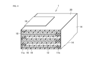
本開示に従うリチウム二次電池に含まれる積層体の製造方法の概略を説明する。図2は、積層体を構成するための各シートを積み重ねる状態を示す模式図である。図3は、図2に示されたシート積層体の切断位置を示す模式図である。図4は、得られた積層体に正極集電体および負極集電体を付加した状態を示す模式図である。 (Production method)
An outline of a method for manufacturing a laminate included in a lithium secondary battery according to the present disclosure will be described. FIG. 2 is a schematic diagram showing a state in which sheets are stacked to form a laminate. FIG. 3 is a schematic diagram showing cutting positions of the sheet laminate shown in FIG. FIG. 4 is a schematic diagram showing a state in which a positive electrode current collector and a negative electrode current collector are added to the obtained laminate.
図2を参照して、積層体を構成する材料となる正極グリーンシート112、負極グリーンシート116、セパレータグリーンシート120、第1の絶縁層グリーンシート(正極側グリーンシート)111a、第2の絶縁層グリーンシート(負極側グリーンシート)111bはそれぞれ別に準備される。典型的には、まず各層を構成する原料を含有するスラリーを調製し、次いで調製したスラリーを樹脂フィルム上にシート状に形成することで、グリーンシートを準備できる。負極グリーンシート116については、主面の一方に集電体層119が形成されていてもよい。所定の幅に切断した各シートを、所定の層構成となるように順に積み重ねる。
Referring to FIG. 2, a positive electrode green sheet 112, a negative electrode green sheet 116, a separator green sheet 120, a first insulating layer green sheet (positive electrode side green sheet) 111a, and a second insulating layer, which are materials constituting the laminate. The green sheets (negative side green sheets) 111b are separately prepared. Typically, a green sheet can be prepared by first preparing a slurry containing raw materials for forming each layer, and then forming the prepared slurry into a sheet on a resin film. A current collector layer 119 may be formed on one of the main surfaces of the negative electrode green sheet 116 . Each sheet cut into a predetermined width is stacked in order so as to form a predetermined layer structure.
積み重ねの際、正極グリーンシート112と第1の絶縁層グリーンシート(正極側グリーンシート)111aとが互いに隣接して一層を形成するように配置する。また、負極グリーンシート116と第2の絶縁層グリーンシート(負極側グリーンシート)111bが互いに隣接して一層を形成するように配置する。セパレータグリーンシート120は幅方向の全体にわたって単独で一層を形成するように配置する。正極グリーンシート112および第1の絶縁層グリーンシート111aは、厚み方向に1枚単独で用いてもよいし、厚み方向に2枚以上同種のシートを連続して重ねる形態であってもよい。同様に、負極グリーンシート116および第2の絶縁層グリーンシート111bは、厚み方向に1枚単独で用いてもよいし、厚み方向に2枚以上同種のシートを連続して重ねる形態であってもよい。厚み方向に同種のシートを2枚以上重ねる場合、焼結段階で重ねたシートが一体化するため、焼結体においては一層となる。集電体層119を有する負極グリーンシート116を2枚重ねる場合には、集電体層119同士が接するように重ねることが好ましい。
When stacked, the positive electrode green sheet 112 and the first insulating layer green sheet (positive electrode side green sheet) 111a are arranged adjacent to each other to form a single layer. Also, the negative electrode green sheet 116 and the second insulating layer green sheet (negative electrode side green sheet) 111b are arranged adjacent to each other to form a single layer. The separator green sheet 120 is arranged to form a single layer over the entire width direction. The positive electrode green sheet 112 and the first insulating layer green sheet 111a may be used singly in the thickness direction, or two or more sheets of the same kind may be continuously stacked in the thickness direction. Similarly, the negative electrode green sheet 116 and the second insulating layer green sheet 111b may be used singly in the thickness direction, or two or more sheets of the same kind may be continuously stacked in the thickness direction. good. When two or more sheets of the same kind are stacked in the thickness direction, the stacked sheets are integrated in the sintering step, so that the sintered body becomes one layer. When two negative electrode green sheets 116 having current collector layers 119 are stacked, it is preferable to stack the current collector layers 119 so that they are in contact with each other.
グリーンシート積層体は、プレスによって、グリーンシート同士を圧着させることができる。プレスの方法は例えば、冷間等方圧加圧(CIP)、温水等方圧加圧(WIP)、静水圧プレス等によることができ、特に制限されない。プレスは、加熱しながら行ってもよい。
The green sheet laminate can be crimped between the green sheets by pressing. The pressing method may be, for example, cold isostatic pressing (CIP), hot water isostatic pressing (WIP), isostatic pressing, or the like, and is not particularly limited. Pressing may be performed while heating.
続いて、グリーンシート積層体を切断する。図3を参照して、グリーンシート積層体は、所定の幅となるように両側面を切断し、また、所定の奥行きを有する積層体が得られるように長さ方向に垂直に切断すればよい。所望の焼結体の形態(全体の寸法、各層の幅および厚み)に応じて、積層の形態および切断箇所の設定をすればよい。なお、図3の例では層構成を簡潔に示しているが、負極グリーンシート116および第2の絶縁層グリーンシート111b、セパレータグリーンシート120、正極グリーンシート112および第1の絶縁層グリーンシート111a、セパレータグリーンシート120をこの順に含むユニットUを繰り返して積層し、さらに多層の積層体としてもよい。所定の形状に切断したグリーンシート積層体について、脱脂および焼成を行い、積層一体焼結体である積層体が得られる。脱脂および焼成は、公知の条件および方法で実施できる。得られた積層一体焼結体における各層の厚みや幅は、例えば、積層一体焼結体をセクロスセクションポリッシャにより研磨し、得られた断面をSEM観察することによって確認できる。
Next, cut the green sheet laminate. Referring to FIG. 3, the green sheet laminate may be cut on both side surfaces so as to have a predetermined width, and cut perpendicularly to the length direction so as to obtain a laminate having a predetermined depth. . Depending on the desired sintered body form (overall dimensions, width and thickness of each layer), the lamination form and cutting points may be set. Although the example of FIG. 3 simply shows the layer structure, the negative electrode green sheet 116 and the second insulating layer green sheet 111b, the separator green sheet 120, the positive electrode green sheet 112 and the first insulating layer green sheet 111a, The unit U including the separator green sheets 120 in this order may be repeatedly laminated to form a multi-layer laminate. The green sheet laminate cut into a predetermined shape is degreased and sintered to obtain a laminate that is a laminated integrally sintered body. Degreasing and baking can be carried out under known conditions and methods. The thickness and width of each layer in the obtained laminated integrally sintered body can be confirmed, for example, by polishing the laminated integrally sintered body with a cross section polisher and observing the obtained cross section with an SEM.
続いて、積層一体焼結体の両側面に集電体を取り付ける。図4を参照して、正極層12が露出する側の側面に正極集電体14を、負極層16が露出する側の側面に負極集電体18を、それぞれ取り付ける。正極集電体14,負極集電体18としては導電性の材料を用いることができ、例えば、アルミニウム箔や銅箔等を用いればよい。正極集電体14は、積層体1の一方の側面全体を覆うように取り付けられ、さらに、積層体1の下面に延在するようにできる。負極集電体18は、積層体1の他方の側面全体を覆うように取り付けられ、さらに、積層体1の上面に延在するようにできる。正極層12と正極集電体14との間、負極層16と負極集電体18の間は、導電性接着剤を用いて接着することができる。導電性接着剤としては例えば、導電性カーボンペーストを用いることができる。導電性接着剤層の厚みは、接着剤層としての効果を発揮し、発明の効果を妨げない限り特に制限されないが、例えば1~500μm程度とできる。
Next, a current collector is attached to both sides of the laminated integrally sintered body. Referring to FIG. 4, the positive electrode current collector 14 is attached to the side surface where the positive electrode layer 12 is exposed, and the negative electrode current collector 18 is attached to the side surface where the negative electrode layer 16 is exposed. A conductive material can be used for the positive electrode current collector 14 and the negative electrode current collector 18, and for example, aluminum foil, copper foil, or the like may be used. The positive electrode current collector 14 is attached so as to cover one entire side surface of the laminate 1 , and can extend to the lower surface of the laminate 1 . The negative electrode current collector 18 is attached so as to cover the entire other side surface of the laminate 1 , and can extend over the upper surface of the laminate 1 . A conductive adhesive can be used to bond between the positive electrode layer 12 and the positive electrode current collector 14 and between the negative electrode layer 16 and the negative electrode current collector 18 . For example, a conductive carbon paste can be used as the conductive adhesive. The thickness of the conductive adhesive layer is not particularly limited as long as it exhibits an effect as an adhesive layer and does not interfere with the effects of the invention, but can be, for example, about 1 to 500 μm.
上記の製造方法で得られた電極を公知の方法および条件を用いて外装体の内部に収容し、電解液を封入して、リチウム二次電池を得ることができる。
A lithium secondary battery can be obtained by housing the electrode obtained by the above manufacturing method inside the exterior body using a known method and conditions, and encapsulating an electrolytic solution.
積層一体焼結体である積層体の幅や奥行き、高さは、所望のリチウム二次電池の形状に応じて適切に選択でき、特に制限されない。例えば、コイン型電池を構成する場合、積層体は、幅3~18mm程度、奥行き3~18mm程度、高さ0.3~5mm程度とできる。この積層体の中に、2~200個のセルが構成されるようにできる。また、幅方向において、外寸幅Wに対する絶縁層幅wの割合は特に制限されないが、0.8~40%程度であることが好ましい。
The width, depth, and height of the laminated body, which is a laminated integrally sintered body, can be appropriately selected according to the desired shape of the lithium secondary battery, and are not particularly limited. For example, when constructing a coin-type battery, the laminate can have a width of about 3 to 18 mm, a depth of about 3 to 18 mm, and a height of about 0.3 to 5 mm. From 2 to 200 cells can be configured in this stack. In the width direction, the ratio of the insulating layer width w to the outer width W is not particularly limited, but is preferably about 0.8 to 40%.
(電解液)
図5を参照して、リチウム二次電池10は電解液22を含んでよい。電解液22は、特に限定されず、リチウム二次電池における電解液として公知の電解液が用いられうる。例えば、溶媒として、エチレンカーボネート(EC)、メチルエチルカーボネート(MEC)、ジエチルカーボネート(DEC)エチルメチルカーボネート(EMC)、プロピレンカーボネート(PC)およびγ-ブチロラクトン(GBL)から選択される1種または2種以上の組み合わせを用いることができる。溶媒に溶解される電解質として、例えば、六フッ化リン酸リチウム(LiPF6)、ホウフッ化リチウム(LiBF4)等のリチウム塩化合物が用いられ得る。電解液22は添加剤としてビニレンカーボネート(VC)、フルオロエチレンカーボネート(FEC)、ビニルエチレンカーボネート(VEC)、およびリチウムジフルオロ(オキサラト)ボレート(LiDFOB)から選択される少なくとも1種をさらに含むものであってもよい。 (Electrolyte)
Referring to FIG. 5, lithiumsecondary battery 10 may include electrolyte solution 22 . The electrolytic solution 22 is not particularly limited, and an electrolytic solution known as an electrolytic solution for lithium secondary batteries can be used. For example, the solvent may be one or two selected from ethylene carbonate (EC), methylethyl carbonate (MEC), diethyl carbonate (DEC), ethylmethyl carbonate (EMC), propylene carbonate (PC) and γ-butyrolactone (GBL). Combinations of species or more can be used. As the electrolyte dissolved in the solvent, for example, lithium salt compounds such as lithium hexafluorophosphate (LiPF 6 ) and lithium borofluoride (LiBF 4 ) can be used. The electrolytic solution 22 further contains at least one selected from vinylene carbonate (VC), fluoroethylene carbonate (FEC), vinylethylene carbonate (VEC), and lithium difluoro(oxalato)borate (LiDFOB) as an additive. may
図5を参照して、リチウム二次電池10は電解液22を含んでよい。電解液22は、特に限定されず、リチウム二次電池における電解液として公知の電解液が用いられうる。例えば、溶媒として、エチレンカーボネート(EC)、メチルエチルカーボネート(MEC)、ジエチルカーボネート(DEC)エチルメチルカーボネート(EMC)、プロピレンカーボネート(PC)およびγ-ブチロラクトン(GBL)から選択される1種または2種以上の組み合わせを用いることができる。溶媒に溶解される電解質として、例えば、六フッ化リン酸リチウム(LiPF6)、ホウフッ化リチウム(LiBF4)等のリチウム塩化合物が用いられ得る。電解液22は添加剤としてビニレンカーボネート(VC)、フルオロエチレンカーボネート(FEC)、ビニルエチレンカーボネート(VEC)、およびリチウムジフルオロ(オキサラト)ボレート(LiDFOB)から選択される少なくとも1種をさらに含むものであってもよい。 (Electrolyte)
Referring to FIG. 5, lithium
電解液22における電解質の濃度は、0.5~2mol/Lであるのが好ましく、より好ましくは0.6~1.9mol/L、さらに好ましくは0.7~1.7mol/L、特に好ましくは0.8~1.5mol/Lである。
The electrolyte concentration in the electrolytic solution 22 is preferably 0.5 to 2 mol/L, more preferably 0.6 to 1.9 mol/L, still more preferably 0.7 to 1.7 mol/L, and particularly preferably. is 0.8 to 1.5 mol/L.
また、電解質として、電解液22以外に、固体電解質やポリマー電解質を用いることができる。その場合には、電解液22の場合と同様、少なくともセパレータ20の気孔内部に電解質が含浸されていることが好ましい。含浸方法は特に限定されないが、例として、電解質を溶融してセパレータ20の気孔内に浸入させる方法、電解質の圧粉体をセパレータ20に押し当てる方法等が挙げられる。
Also, as the electrolyte, a solid electrolyte or a polymer electrolyte can be used in addition to the electrolytic solution 22 . In that case, it is preferable that at least the inside of the pores of the separator 20 is impregnated with the electrolyte, as in the case of the electrolytic solution 22 . The impregnation method is not particularly limited, but examples thereof include a method of melting the electrolyte and infiltrating into the pores of the separator 20 and a method of pressing the compacted powder of the electrolyte against the separator 20 .
[実施例]
以下、実施例および比較例を示して本開示のリチウム二次電池をより詳しく説明する。
[実施例1]
以下の1~7に記載の方法に従ってリチウム二次電池を作製した。得られたリチウム二次電池について、8、9に記載の方法によって評価を行った。 [Example]
EXAMPLES Hereinafter, the lithium secondary battery of the present disclosure will be described in more detail with reference to examples and comparative examples.
[Example 1]
A lithium secondary battery was produced according to the methods described in 1 to 7 below. The obtained lithium secondary battery was evaluated by the methods described in 8 and 9.
1.積層体の作製
(1)~(5)の条件および方法で積層体を構成する各層のグリーンシートを作製した。なお、(1)~(5)において、スラリーの粘度はブルックフィールド社製LVT型粘度計で測定した。スラリーをPETフィルム上に成形する際にはドクターブレード法を用いた。 1. Production of Laminate A green sheet for each layer constituting the laminate was produced under the conditions and methods of (1) to (5). In (1) to (5), the viscosity of the slurry was measured with an LVT viscometer manufactured by Brookfield. A doctor blade method was used to form the slurry on the PET film.
(1)~(5)の条件および方法で積層体を構成する各層のグリーンシートを作製した。なお、(1)~(5)において、スラリーの粘度はブルックフィールド社製LVT型粘度計で測定した。スラリーをPETフィルム上に成形する際にはドクターブレード法を用いた。 1. Production of Laminate A green sheet for each layer constituting the laminate was produced under the conditions and methods of (1) to (5). In (1) to (5), the viscosity of the slurry was measured with an LVT viscometer manufactured by Brookfield. A doctor blade method was used to form the slurry on the PET film.
(1)LCOグリーンシート(正極グリーンシート)の作製
Li/Coのモル比が1.01となるように秤量されたCo3O4粉末(正同化学工業株式会社製)とLi2CO3粉末(本荘ケミカル株式会社製)を混合後、780℃で5時間保持し、得られた粉末をポットミルにて体積基準D50が0.4μmとなるように粉砕してLCO板状粒子からなる粉末を得た。得られたLCO粉末100重量部と、分散媒(トルエン:イソプロパノール=1:1)100重量部と、バインダー(ポリビニルブチラール:品番BM-2、積水化学工業株式会社製)8重量部と、可塑剤(DOP:Di(2-ethylhexyl)phthalate、黒金化成株式会社製)2重量部と、分散剤(製品名レオドールSP-O30、花王株式会社製)4.5重量部とを混合した。得られた混合物を減圧下で撹拌して脱泡するとともに、粘度を4000cPに調整することによって、LCOスラリーを調製した。調製されたスラリーをPETフィルム上にシート状に成形することによって、LCOグリーンシートを形成した。焼成後の正極層の厚みが10μmになるように調整した。 (1) Preparation of LCO green sheet (positive electrode green sheet) Co 3 O 4 powder (manufactured by Seido Chemical Industry Co., Ltd.) and Li 2 CO 3 powder weighed so that the molar ratio of Li/Co was 1.01. (manufactured by Honjo Chemical Co., Ltd.) was mixed and held at 780° C. for 5 hours. Obtained. 100 parts by weight of the obtained LCO powder, 100 parts by weight of a dispersion medium (toluene: isopropanol = 1:1), 8 parts by weight of a binder (polyvinyl butyral: product number BM-2, manufactured by Sekisui Chemical Co., Ltd.), and a plasticizer 2 parts by weight of (DOP: Di(2-ethylhexyl) phthalate, manufactured by Kurogane Kasei Co., Ltd.) and 4.5 parts by weight of a dispersant (product name: Rhodol SP-O30, manufactured by Kao Corporation) were mixed. An LCO slurry was prepared by stirring the obtained mixture under reduced pressure to remove air bubbles and adjusting the viscosity to 4000 cP. An LCO green sheet was formed by sheet-forming the prepared slurry on a PET film. The thickness of the positive electrode layer after firing was adjusted to 10 μm.
Li/Coのモル比が1.01となるように秤量されたCo3O4粉末(正同化学工業株式会社製)とLi2CO3粉末(本荘ケミカル株式会社製)を混合後、780℃で5時間保持し、得られた粉末をポットミルにて体積基準D50が0.4μmとなるように粉砕してLCO板状粒子からなる粉末を得た。得られたLCO粉末100重量部と、分散媒(トルエン:イソプロパノール=1:1)100重量部と、バインダー(ポリビニルブチラール:品番BM-2、積水化学工業株式会社製)8重量部と、可塑剤(DOP:Di(2-ethylhexyl)phthalate、黒金化成株式会社製)2重量部と、分散剤(製品名レオドールSP-O30、花王株式会社製)4.5重量部とを混合した。得られた混合物を減圧下で撹拌して脱泡するとともに、粘度を4000cPに調整することによって、LCOスラリーを調製した。調製されたスラリーをPETフィルム上にシート状に成形することによって、LCOグリーンシートを形成した。焼成後の正極層の厚みが10μmになるように調整した。 (1) Preparation of LCO green sheet (positive electrode green sheet) Co 3 O 4 powder (manufactured by Seido Chemical Industry Co., Ltd.) and Li 2 CO 3 powder weighed so that the molar ratio of Li/Co was 1.01. (manufactured by Honjo Chemical Co., Ltd.) was mixed and held at 780° C. for 5 hours. Obtained. 100 parts by weight of the obtained LCO powder, 100 parts by weight of a dispersion medium (toluene: isopropanol = 1:1), 8 parts by weight of a binder (polyvinyl butyral: product number BM-2, manufactured by Sekisui Chemical Co., Ltd.), and a plasticizer 2 parts by weight of (DOP: Di(2-ethylhexyl) phthalate, manufactured by Kurogane Kasei Co., Ltd.) and 4.5 parts by weight of a dispersant (product name: Rhodol SP-O30, manufactured by Kao Corporation) were mixed. An LCO slurry was prepared by stirring the obtained mixture under reduced pressure to remove air bubbles and adjusting the viscosity to 4000 cP. An LCO green sheet was formed by sheet-forming the prepared slurry on a PET film. The thickness of the positive electrode layer after firing was adjusted to 10 μm.
(2)LTOグリーンシート(負極グリーンシート)の作製
LTO粉末(体積基準D50粒径0.06μm、シグマアルドリッチジャパン合同会社製)100重量部と、分散媒(トルエン:イソプロパノール=1:1)100重量部と、バインダー(ポリビニルブチラール:品番BM-2、積水化学工業株式会社製)20重量部と、可塑剤(DOP:Di(2-ethylhexyl)phthalate、黒金化成株式会社製)4重量部と、分散剤(製品名レオドールSP-O30、花王株式会社製)2重量部とを混合した。得られた負極原料混合物を減圧下で撹拌して脱泡するとともに、粘度を4000cPに調整することによって、LTOスラリーを調製した。調製されたスラリーをPETフィルム上にシート状に成形することによって、LTOグリーンシートを形成した。焼成後の負極層の厚みが10μmになるように調整した。 (2) Preparation of LTO green sheet (negative electrode green sheet) 100 parts by weight of LTO powder (volume-based D50 particle size 0.06 µm, manufactured by Sigma-Aldrich Japan LLC) and 100 parts of a dispersion medium (toluene: isopropanol = 1:1) Parts by weight, binder (polyvinyl butyral: product number BM-2, manufactured by Sekisui Chemical Co., Ltd.) 20 parts by weight, and plasticizer (DOP: Di (2-ethylhexyl) phthalate, manufactured by Kurogane Kasei Co., Ltd.) 4 parts by weight , and 2 parts by weight of a dispersant (product name: Rheodol SP-O30, manufactured by Kao Corporation). An LTO slurry was prepared by stirring the obtained negative electrode raw material mixture under reduced pressure to remove air bubbles and adjusting the viscosity to 4000 cP. An LTO green sheet was formed by forming the prepared slurry into a sheet on a PET film. The thickness of the negative electrode layer after firing was adjusted to 10 μm.
LTO粉末(体積基準D50粒径0.06μm、シグマアルドリッチジャパン合同会社製)100重量部と、分散媒(トルエン:イソプロパノール=1:1)100重量部と、バインダー(ポリビニルブチラール:品番BM-2、積水化学工業株式会社製)20重量部と、可塑剤(DOP:Di(2-ethylhexyl)phthalate、黒金化成株式会社製)4重量部と、分散剤(製品名レオドールSP-O30、花王株式会社製)2重量部とを混合した。得られた負極原料混合物を減圧下で撹拌して脱泡するとともに、粘度を4000cPに調整することによって、LTOスラリーを調製した。調製されたスラリーをPETフィルム上にシート状に成形することによって、LTOグリーンシートを形成した。焼成後の負極層の厚みが10μmになるように調整した。 (2) Preparation of LTO green sheet (negative electrode green sheet) 100 parts by weight of LTO powder (volume-based D50 particle size 0.06 µm, manufactured by Sigma-Aldrich Japan LLC) and 100 parts of a dispersion medium (toluene: isopropanol = 1:1) Parts by weight, binder (polyvinyl butyral: product number BM-2, manufactured by Sekisui Chemical Co., Ltd.) 20 parts by weight, and plasticizer (DOP: Di (2-ethylhexyl) phthalate, manufactured by Kurogane Kasei Co., Ltd.) 4 parts by weight , and 2 parts by weight of a dispersant (product name: Rheodol SP-O30, manufactured by Kao Corporation). An LTO slurry was prepared by stirring the obtained negative electrode raw material mixture under reduced pressure to remove air bubbles and adjusting the viscosity to 4000 cP. An LTO green sheet was formed by forming the prepared slurry into a sheet on a PET film. The thickness of the negative electrode layer after firing was adjusted to 10 μm.
(2´)集電体層の形成
(2)で作製したLTOグリーンシートの片面に、印刷機にてAuペースト(田中貴金属社製、製品名:GB-2706)を印刷した。印刷層の厚みは、焼成後0.2μmになるようにした。 (2′) Formation of Current Collector Layer On one side of the LTO green sheet produced in (2), Au paste (manufactured by Tanaka Kikinzoku Co., Ltd., product name: GB-2706) was printed with a printing machine. The thickness of the printed layer was set to 0.2 μm after firing.
(2)で作製したLTOグリーンシートの片面に、印刷機にてAuペースト(田中貴金属社製、製品名:GB-2706)を印刷した。印刷層の厚みは、焼成後0.2μmになるようにした。 (2′) Formation of Current Collector Layer On one side of the LTO green sheet produced in (2), Au paste (manufactured by Tanaka Kikinzoku Co., Ltd., product name: GB-2706) was printed with a printing machine. The thickness of the printed layer was set to 0.2 μm after firing.
(3)セパレータグリーンシートの作製
炭酸マグネシウム粉末(神島化学工業株式会社製)を900℃で5時間熱処理してMgO粉末を得た。得られたMgO粉末とガラスフリット(日本フリット株式会社製、CK0199)を重量比7:3で混合した。得られた混合粉末(体積基準D50粒径0.4μm)100重量部と、分散媒(トルエン:イソプロパノール=1:1)100重量部と、バインダー(ポリビニルブチラール:品番BM-2、積水化学工業株式会社製)30重量部と、可塑剤(DOP:Di(2-ethylhexyl)phthalate、黒金化成株式会社製)6重量部と、分散剤(製品名レオドールSP-O30、花王株式会社製)2重量部とを混合した。得られた原料混合物を減圧下で撹拌して脱泡するとともに、粘度を4000cPに調整することによって、スラリーを調製した。調製されたスラリーをPETフィルム上にシート状に成形することによって、セパレータグリーンシートを形成した。焼成後のセパレータ層の厚みは25μmになるようにした。 (3) Production of Separator Green Sheet Magnesium carbonate powder (manufactured by Kamishima Chemical Co., Ltd.) was heat-treated at 900° C. for 5 hours to obtain MgO powder. The obtained MgO powder and glass frit (CK0199 manufactured by Nippon Frit Co., Ltd.) were mixed at a weight ratio of 7:3. The resulting mixed powder (volume-based D 50 particle size 0.4 μm) 100 parts by weight, a dispersion medium (toluene: isopropanol = 1: 1) 100 parts by weight, a binder (polyvinyl butyral: product number BM-2, Sekisui Chemical Co., Ltd. Co., Ltd.) 30 parts by weight, a plasticizer (DOP: Di (2-ethylhexyl) phthalate, manufactured by Kurogane Kasei Co., Ltd.) 6 parts by weight, and a dispersant (product name Rhodol SP-O30, manufactured by Kao Corporation) 2 parts by weight. A slurry was prepared by stirring the obtained raw material mixture under reduced pressure to remove air bubbles and adjusting the viscosity to 4000 cP. A separator green sheet was formed by forming the prepared slurry into a sheet on a PET film. The thickness of the separator layer after baking was set to 25 μm.
炭酸マグネシウム粉末(神島化学工業株式会社製)を900℃で5時間熱処理してMgO粉末を得た。得られたMgO粉末とガラスフリット(日本フリット株式会社製、CK0199)を重量比7:3で混合した。得られた混合粉末(体積基準D50粒径0.4μm)100重量部と、分散媒(トルエン:イソプロパノール=1:1)100重量部と、バインダー(ポリビニルブチラール:品番BM-2、積水化学工業株式会社製)30重量部と、可塑剤(DOP:Di(2-ethylhexyl)phthalate、黒金化成株式会社製)6重量部と、分散剤(製品名レオドールSP-O30、花王株式会社製)2重量部とを混合した。得られた原料混合物を減圧下で撹拌して脱泡するとともに、粘度を4000cPに調整することによって、スラリーを調製した。調製されたスラリーをPETフィルム上にシート状に成形することによって、セパレータグリーンシートを形成した。焼成後のセパレータ層の厚みは25μmになるようにした。 (3) Production of Separator Green Sheet Magnesium carbonate powder (manufactured by Kamishima Chemical Co., Ltd.) was heat-treated at 900° C. for 5 hours to obtain MgO powder. The obtained MgO powder and glass frit (CK0199 manufactured by Nippon Frit Co., Ltd.) were mixed at a weight ratio of 7:3. The resulting mixed powder (volume-based D 50 particle size 0.4 μm) 100 parts by weight, a dispersion medium (toluene: isopropanol = 1: 1) 100 parts by weight, a binder (polyvinyl butyral: product number BM-2, Sekisui Chemical Co., Ltd. Co., Ltd.) 30 parts by weight, a plasticizer (DOP: Di (2-ethylhexyl) phthalate, manufactured by Kurogane Kasei Co., Ltd.) 6 parts by weight, and a dispersant (product name Rhodol SP-O30, manufactured by Kao Corporation) 2 parts by weight. A slurry was prepared by stirring the obtained raw material mixture under reduced pressure to remove air bubbles and adjusting the viscosity to 4000 cP. A separator green sheet was formed by forming the prepared slurry into a sheet on a PET film. The thickness of the separator layer after baking was set to 25 μm.
(4)第1の絶縁層(正極側絶縁層)グリーンシートの作製
炭酸マグネシウム粉末(神島化学工業株式会社製)を900℃で5時間熱処理してMgO粉末を得た。得られたMgO粉末とTiO2(石原産業株式会社製、CR-EL)を重量比6:4で混合した。得られた混合粉末(体積基準D50粒径0.4μm)100重量部と、分散媒(トルエン:イソプロパノール=1:1)100重量部と、バインダー(ポリビニルブチラール:品番BM-2、積水化学工業株式会社製)30重量部と、可塑剤(DOP:Di(2-ethylhexyl)phthalate、黒金化成株式会社製)6重量部と、分散剤(製品名レオドールSP-O30、花王株式会社製)2重量部とを混合した。得られた原料混合物を減圧下で撹拌して脱泡するとともに、粘度を4000cPに調整することによって、スラリーを調製した。調製されたスラリーをPETフィルム上にシート状に成形することによって、第1の絶縁層グリーンシートを形成した。焼成後の第1の絶縁層の厚みは10μmになるようにした。 (4) Preparation of First Insulating Layer (Positive Electrode Side Insulating Layer) Green Sheet Magnesium carbonate powder (manufactured by Kojima Chemical Co., Ltd.) was heat-treated at 900° C. for 5 hours to obtain MgO powder. The obtained MgO powder and TiO 2 (manufactured by Ishihara Sangyo Co., Ltd., CR-EL) were mixed at a weight ratio of 6:4. The resulting mixed powder (volume-based D 50 particle size 0.4 μm) 100 parts by weight, a dispersion medium (toluene: isopropanol = 1: 1) 100 parts by weight, a binder (polyvinyl butyral: product number BM-2, Sekisui Chemical Co., Ltd. Co., Ltd.) 30 parts by weight, a plasticizer (DOP: Di (2-ethylhexyl) phthalate, manufactured by Kurogane Kasei Co., Ltd.) 6 parts by weight, and a dispersant (product name Rhodol SP-O30, manufactured by Kao Corporation) 2 parts by weight. A slurry was prepared by stirring the obtained raw material mixture under reduced pressure to remove air bubbles and adjusting the viscosity to 4000 cP. A first insulating layer green sheet was formed by forming the prepared slurry into a sheet on a PET film. The thickness of the first insulating layer after firing was set to 10 μm.
炭酸マグネシウム粉末(神島化学工業株式会社製)を900℃で5時間熱処理してMgO粉末を得た。得られたMgO粉末とTiO2(石原産業株式会社製、CR-EL)を重量比6:4で混合した。得られた混合粉末(体積基準D50粒径0.4μm)100重量部と、分散媒(トルエン:イソプロパノール=1:1)100重量部と、バインダー(ポリビニルブチラール:品番BM-2、積水化学工業株式会社製)30重量部と、可塑剤(DOP:Di(2-ethylhexyl)phthalate、黒金化成株式会社製)6重量部と、分散剤(製品名レオドールSP-O30、花王株式会社製)2重量部とを混合した。得られた原料混合物を減圧下で撹拌して脱泡するとともに、粘度を4000cPに調整することによって、スラリーを調製した。調製されたスラリーをPETフィルム上にシート状に成形することによって、第1の絶縁層グリーンシートを形成した。焼成後の第1の絶縁層の厚みは10μmになるようにした。 (4) Preparation of First Insulating Layer (Positive Electrode Side Insulating Layer) Green Sheet Magnesium carbonate powder (manufactured by Kojima Chemical Co., Ltd.) was heat-treated at 900° C. for 5 hours to obtain MgO powder. The obtained MgO powder and TiO 2 (manufactured by Ishihara Sangyo Co., Ltd., CR-EL) were mixed at a weight ratio of 6:4. The resulting mixed powder (volume-based D 50 particle size 0.4 μm) 100 parts by weight, a dispersion medium (toluene: isopropanol = 1: 1) 100 parts by weight, a binder (polyvinyl butyral: product number BM-2, Sekisui Chemical Co., Ltd. Co., Ltd.) 30 parts by weight, a plasticizer (DOP: Di (2-ethylhexyl) phthalate, manufactured by Kurogane Kasei Co., Ltd.) 6 parts by weight, and a dispersant (product name Rhodol SP-O30, manufactured by Kao Corporation) 2 parts by weight. A slurry was prepared by stirring the obtained raw material mixture under reduced pressure to remove air bubbles and adjusting the viscosity to 4000 cP. A first insulating layer green sheet was formed by forming the prepared slurry into a sheet on a PET film. The thickness of the first insulating layer after firing was set to 10 μm.
(5)第2の絶縁層(負極側絶縁層)グリーンシートの作製
(4)と同様にスラリーを調製した。調製されたスラリーをPETフィルム上にシート状に成形することによって、第2の絶縁層グリーンシートを形成した。焼成後の第2の絶縁層の厚みは10μmになるようにした。 (5) Preparation of second insulating layer (negative electrode side insulating layer) green sheet Slurry was prepared in the same manner as in (4). A second insulating layer green sheet was formed by forming the prepared slurry into a sheet on a PET film. The thickness of the second insulating layer after firing was set to 10 μm.
(4)と同様にスラリーを調製した。調製されたスラリーをPETフィルム上にシート状に成形することによって、第2の絶縁層グリーンシートを形成した。焼成後の第2の絶縁層の厚みは10μmになるようにした。 (5) Preparation of second insulating layer (negative electrode side insulating layer) green sheet Slurry was prepared in the same manner as in (4). A second insulating layer green sheet was formed by forming the prepared slurry into a sheet on a PET film. The thickness of the second insulating layer after firing was set to 10 μm.
2.シートの切断
1.で得られたグリーンシートをそれぞれ次の幅に切断した。
(1)LCOグリーンシート(正極グリーンシート) 7250μm
(2)LTOグリーンシート(負極グリーンシート) 7250μm
(3)セパレータグリーンシート 10000μm
(4)第1の絶縁層(正極側絶縁層)グリーンシート 2750μm
(5)第2の絶縁層(負極側絶縁層)グリーンシート 2750μm 2. Sheet cutting 1 . The green sheets obtained in 1 were cut into the following widths.
(1) LCO green sheet (positive electrode green sheet) 7250 μm
(2) LTO green sheet (negative electrode green sheet) 7250 μm
(3) Separator green sheet 10000 μm
(4) First insulating layer (positive electrode side insulating layer) green sheet 2750 µm
(5) Second insulating layer (negative electrode side insulating layer) green sheet 2750 µm
3.積層、圧着、切断および焼成
[図6]に示すとおり各種グリーンシートを積層した。なお、LTOグリーンシートが2枚重ねられる場合には、集電体層同士が互いに接するように積層した。得られた積層体をCIP(冷間等方圧加圧法)により100kgf/cm2でプレスしてグリーンシート同士を圧着し、未焼成グリーンシート積層体を得た。続いて、[図3]に示すように未焼成グリーンシート積層体をトムソン刃で切断した。切断は、幅方向の両端をそれぞれ2500μmカットするとともに、奥行きが5000μmとなる長さとした。切断後の未焼成積層体を、室温から600℃まで昇温して5時間脱脂した後、800℃まで昇温して10分間保持する焼成を行い、その後冷却した。このようにして積層一体焼結体を得た。積層一体焼結体に形成されるセル数は11である。 3. Lamination, Crimp, Cutting and Firing Various green sheets were laminated as shown in FIG. When two LTO green sheets were stacked, they were stacked so that the current collector layers were in contact with each other. The obtained laminate was pressed at 100 kgf/cm 2 by CIP (cold isostatic pressing) to press the green sheets together to obtain an unfired green sheet laminate. Subsequently, as shown in FIG. 3, the unfired green sheet laminate was cut with a Thomson blade. The cutting was performed by cutting 2500 μm at both ends in the width direction and making the length of 5000 μm in depth. The unfired laminated body after cutting was heated from room temperature to 600° C., degreased for 5 hours, heated to 800° C., fired for 10 minutes, and then cooled. Thus, a laminated integrally sintered body was obtained. The number of cells formed in the laminated integrated sintered body is eleven.
[図6]に示すとおり各種グリーンシートを積層した。なお、LTOグリーンシートが2枚重ねられる場合には、集電体層同士が互いに接するように積層した。得られた積層体をCIP(冷間等方圧加圧法)により100kgf/cm2でプレスしてグリーンシート同士を圧着し、未焼成グリーンシート積層体を得た。続いて、[図3]に示すように未焼成グリーンシート積層体をトムソン刃で切断した。切断は、幅方向の両端をそれぞれ2500μmカットするとともに、奥行きが5000μmとなる長さとした。切断後の未焼成積層体を、室温から600℃まで昇温して5時間脱脂した後、800℃まで昇温して10分間保持する焼成を行い、その後冷却した。このようにして積層一体焼結体を得た。積層一体焼結体に形成されるセル数は11である。 3. Lamination, Crimp, Cutting and Firing Various green sheets were laminated as shown in FIG. When two LTO green sheets were stacked, they were stacked so that the current collector layers were in contact with each other. The obtained laminate was pressed at 100 kgf/cm 2 by CIP (cold isostatic pressing) to press the green sheets together to obtain an unfired green sheet laminate. Subsequently, as shown in FIG. 3, the unfired green sheet laminate was cut with a Thomson blade. The cutting was performed by cutting 2500 μm at both ends in the width direction and making the length of 5000 μm in depth. The unfired laminated body after cutting was heated from room temperature to 600° C., degreased for 5 hours, heated to 800° C., fired for 10 minutes, and then cooled. Thus, a laminated integrally sintered body was obtained. The number of cells formed in the laminated integrated sintered body is eleven.
4.導電性カーボンペーストの調製
純水に対してバインダー(CMC:MAC350HC、日本製紙株式会社製)が1.2wt%となるように秤量し、スターラー混合で溶解させて、1.2wt%CMC溶液を得た。カーボン分散液(品番:BPW―229、日本黒鉛株式会社製)および分散材溶液(品番LB―300、昭和電工株式会社製)を準備した。続いて、カーボン分散液と、分散材溶液と、1.2wt%CMC溶液とが、0.22:0.29:1となるように秤量し、これを自公転ミキサーにより混合して、導電性カーボンペーストを調製した。 4. Preparation of conductive carbon paste Binder (CMC: MAC350HC, manufactured by Nippon Paper Industries Co., Ltd.) is weighed to 1.2 wt% with respect to pure water, and dissolved by stirring with a stirrer to obtain a 1.2 wt% CMC solution. rice field. A carbon dispersion liquid (product number: BPW-229, manufactured by Nippon Graphite Co., Ltd.) and a dispersing agent solution (product number: LB-300, manufactured by Showa Denko KK) were prepared. Subsequently, the carbon dispersion, the dispersant solution, and the 1.2 wt% CMC solution were weighed so that the ratio was 0.22:0.29:1, and mixed by a rotation/revolution mixer to obtain a conductive A carbon paste was prepared.
純水に対してバインダー(CMC:MAC350HC、日本製紙株式会社製)が1.2wt%となるように秤量し、スターラー混合で溶解させて、1.2wt%CMC溶液を得た。カーボン分散液(品番:BPW―229、日本黒鉛株式会社製)および分散材溶液(品番LB―300、昭和電工株式会社製)を準備した。続いて、カーボン分散液と、分散材溶液と、1.2wt%CMC溶液とが、0.22:0.29:1となるように秤量し、これを自公転ミキサーにより混合して、導電性カーボンペーストを調製した。 4. Preparation of conductive carbon paste Binder (CMC: MAC350HC, manufactured by Nippon Paper Industries Co., Ltd.) is weighed to 1.2 wt% with respect to pure water, and dissolved by stirring with a stirrer to obtain a 1.2 wt% CMC solution. rice field. A carbon dispersion liquid (product number: BPW-229, manufactured by Nippon Graphite Co., Ltd.) and a dispersing agent solution (product number: LB-300, manufactured by Showa Denko KK) were prepared. Subsequently, the carbon dispersion, the dispersant solution, and the 1.2 wt% CMC solution were weighed so that the ratio was 0.22:0.29:1, and mixed by a rotation/revolution mixer to obtain a conductive A carbon paste was prepared.
5.積層一体焼結体の正極露出面とアルミニウム箔を導電性カーボンペーストで接合
正極集電体としてのアルミニウム箔上に4.で得た導電性カーボンペーストをスクリーン印刷した。未乾燥の印刷パターン(導電性カーボンペーストが塗布された領域)内に収まるように、3.で得た積層一体焼結体の正極露出面が接着されるように載置し、指で軽く押さえつけた後に、50℃で60分間真空乾燥させた。このようにして、積層一体焼結体の正極露出面と正極集電体とが、導電性カーボン接着層を介して接着された。なお、導電性カーボン接着剤層の厚みは30μmとした。 5. 4. Joining the exposed surface of the positive electrode of the laminated integrated sintered body and the aluminum foil with a conductive carbon paste. The conductive carbon paste obtained in was screen printed. 3. so that it fits within the undried printed pattern (the area where the conductive carbon paste is applied); The laminate integrally sintered body obtained in 1. was placed so that the exposed surface of the positive electrode was adhered thereto, lightly pressed with a finger, and then vacuum-dried at 50° C. for 60 minutes. In this way, the positive electrode exposed surface of the laminated integrally sintered body and the positive electrode current collector were adhered via the conductive carbon adhesive layer. The thickness of the conductive carbon adhesive layer was set to 30 μm.
正極集電体としてのアルミニウム箔上に4.で得た導電性カーボンペーストをスクリーン印刷した。未乾燥の印刷パターン(導電性カーボンペーストが塗布された領域)内に収まるように、3.で得た積層一体焼結体の正極露出面が接着されるように載置し、指で軽く押さえつけた後に、50℃で60分間真空乾燥させた。このようにして、積層一体焼結体の正極露出面と正極集電体とが、導電性カーボン接着層を介して接着された。なお、導電性カーボン接着剤層の厚みは30μmとした。 5. 4. Joining the exposed surface of the positive electrode of the laminated integrated sintered body and the aluminum foil with a conductive carbon paste. The conductive carbon paste obtained in was screen printed. 3. so that it fits within the undried printed pattern (the area where the conductive carbon paste is applied); The laminate integrally sintered body obtained in 1. was placed so that the exposed surface of the positive electrode was adhered thereto, lightly pressed with a finger, and then vacuum-dried at 50° C. for 60 minutes. In this way, the positive electrode exposed surface of the laminated integrally sintered body and the positive electrode current collector were adhered via the conductive carbon adhesive layer. The thickness of the conductive carbon adhesive layer was set to 30 μm.
6.積層一体焼結体の負極露出面とアルミニウム箔を導電性カーボンペーストで接合
5.と同様にして、積層一体焼結体の負極露出面に、導電性カーボン接着層を介して、負極集電体であるアルミニウム箔を接着した。 6. 5. Joining the negative electrode exposed surface of the laminated integrally sintered body and the aluminum foil with a conductive carbon paste. In the same manner as above, an aluminum foil as a negative electrode current collector was adhered to the negative electrode exposed surface of the laminated integrally sintered body via a conductive carbon adhesive layer.
5.と同様にして、積層一体焼結体の負極露出面に、導電性カーボン接着層を介して、負極集電体であるアルミニウム箔を接着した。 6. 5. Joining the negative electrode exposed surface of the laminated integrally sintered body and the aluminum foil with a conductive carbon paste. In the same manner as above, an aluminum foil as a negative electrode current collector was adhered to the negative electrode exposed surface of the laminated integrally sintered body via a conductive carbon adhesive layer.
7.リチウム二次電池の作製
電池ケースを構成することになる正極缶と負極缶との間に、正極缶から負極缶に向かって、正極集電体、積層一体焼結体、並びに負極集電体がこの順に積層されるように収容し、電解液を充填した後に、ガスケットを介して正極缶と負極缶とをかしめることによって封止した。こうして、直径20mm、厚み1.6mmのコインセル形のリチウム二次電池を作製した。電解液としては、プロピレンカーボネート(PC)およびγ-ブチロラクトン(GBL)を1:3の体積比で混合した有機溶媒に、LiPF6を1.5mol/Lの濃度となるように溶解させた液を用いた。 7. Fabrication of Lithium Secondary Battery Between the positive electrode can and the negative electrode can that constitute the battery case, the positive electrode current collector, the laminated integrated sintered body, and the negative electrode current collector are placed from the positive electrode can toward the negative electrode can. After being stacked in this order and filled with an electrolytic solution, the positive electrode can and the negative electrode can were sealed by crimping through a gasket. Thus, a coin cell type lithium secondary battery having a diameter of 20 mm and a thickness of 1.6 mm was produced. As the electrolytic solution, LiPF 6 was dissolved to a concentration of 1.5 mol/L in an organic solvent in which propylene carbonate (PC) and γ-butyrolactone (GBL) were mixed at a volume ratio of 1:3. Using.
電池ケースを構成することになる正極缶と負極缶との間に、正極缶から負極缶に向かって、正極集電体、積層一体焼結体、並びに負極集電体がこの順に積層されるように収容し、電解液を充填した後に、ガスケットを介して正極缶と負極缶とをかしめることによって封止した。こうして、直径20mm、厚み1.6mmのコインセル形のリチウム二次電池を作製した。電解液としては、プロピレンカーボネート(PC)およびγ-ブチロラクトン(GBL)を1:3の体積比で混合した有機溶媒に、LiPF6を1.5mol/Lの濃度となるように溶解させた液を用いた。 7. Fabrication of Lithium Secondary Battery Between the positive electrode can and the negative electrode can that constitute the battery case, the positive electrode current collector, the laminated integrated sintered body, and the negative electrode current collector are placed from the positive electrode can toward the negative electrode can. After being stacked in this order and filled with an electrolytic solution, the positive electrode can and the negative electrode can were sealed by crimping through a gasket. Thus, a coin cell type lithium secondary battery having a diameter of 20 mm and a thickness of 1.6 mm was produced. As the electrolytic solution, LiPF 6 was dissolved to a concentration of 1.5 mol/L in an organic solvent in which propylene carbonate (PC) and γ-butyrolactone (GBL) were mixed at a volume ratio of 1:3. Using.
8.評価1:積層一体焼結体の計測および計算
(1)積層一体焼結体の外寸幅の測定
ワンショット3D形状測定機(株式会社キーエンス製、VR3000)を用いて、積層一体焼結体の外寸厚み(T)を測定した。
(2)絶縁層厚みの測定
積層一体焼結体をセクロスセクションポリッシャ(CP)(日本電子株式会社製、IB-15000CP)により研磨し、得られた断面をSEM観察(日本電子製、JSM―IT―500)した。
(3)各パラメータの算出
絶縁層の厚みは、積層一体焼結体に含まれる12層の絶縁層についてそれぞれ計測し、それらの平均taveを算出した。次の式により、外寸厚みTに対する絶縁層厚み平均taveの割合(%)を算出した。
絶縁層厚み平均/外寸厚み[%]=(tave/T)×100
12層の絶縁層のそれぞれについて各絶縁層の厚みと絶縁層厚み平均taveとの差分を算出し、差分の平均値を「絶縁層厚みのばらつきの平均ts」とした。次の式により、絶縁層厚み平均taveに対する、絶縁層厚みのばらつきの平均tsの割合(%)を算出した。
絶縁層厚みばらつき平均/絶縁層厚み平均[%]=(ts/tave)×100 8. Evaluation 1: Measurement and calculation of laminated integrally sintered body (1) Measurement of outer dimension width of laminated integrally sintered body Using a one-shot 3D shape measuring machine (manufactured by Keyence Corporation, VR3000), laminated integrally sintered body The outer dimension thickness (T) was measured.
(2) Measurement of insulating layer thickness The laminated integrated sintered body is polished with a cross section polisher (CP) (manufactured by JEOL Ltd., IB-15000CP), and the resulting cross section is observed by SEM (manufactured by JEOL Ltd., JSM-IT -500).
(3) Calculation of Each Parameter The thickness of the insulating layer was measured for each of the 12 insulating layers included in the laminated integrally sintered body, and the average t ave was calculated. The ratio (%) of the insulation layer thickness average t ave to the outer dimension thickness T was calculated by the following formula.
Insulating layer thickness average/external thickness [%] = (t ave /T) x 100
For each of the 12 insulating layers, the difference between the thickness of each insulating layer and the average insulating layer thickness t ave was calculated, and the average value of the differences was defined as the “average t s of variations in insulating layer thickness”. The ratio (%) of the average t s of variations in the thickness of the insulating layer to the average thickness t ave of the insulating layer was calculated from the following formula.
Insulating layer thickness variation average/insulating layer thickness average [%] = (t s /t ave ) x 100
9.クラック歩留まりの評価
積層一体焼結体を20個以上作製し、ひとつひとつのサンプルを目視にて観察した。目視にてクラックが確認されなかったものは合格、クラックが1つでも確認されたものは不合格とした。なお、クラックの大きさ、数に関わらず、目視にてクラックが確認されたものはすべて不合格とした。次の式にて、クラック歩留まりを算出した。
クラック歩留まり(%)=(合格サンプル数/サンプル全数)×100 9. Evaluation of Crack Yield Twenty or more laminated integral sintered bodies were produced, and each sample was visually observed. A sample in which no cracks were visually observed was regarded as acceptable, and a sample in which even one crack was confirmed was regarded as unacceptable. In addition, regardless of the size and number of cracks, all samples visually confirmed to have cracks were rejected. The crack yield was calculated by the following formula.
Crack yield (%) = (number of acceptable samples/total number of samples) x 100
[実施例2]
LCOグリーンシート(正極グリーンシート)、LTOグリーンシート(負極グリーンシート)について、第1の絶縁層(正極側絶縁層)グリーンシートおよび第2の絶縁層(負極側絶縁層)グリーンシートのそれぞれについて、焼成後の層の厚みの平均が20μmになるように調整した。また、積層体における繰り返しユニット数は4とした。これら以外は実施例1と同様にリチウム二次電池を作製し、計測およびクラック歩留まりを評価した。 [Example 2]
Regarding the LCO green sheet (positive electrode green sheet), the LTO green sheet (negative electrode green sheet), the first insulating layer (positive electrode side insulating layer) green sheet and the second insulating layer (negative electrode side insulating layer) green sheet, It was adjusted so that the average thickness of the layer after firing was 20 μm. Also, the number of repeating units in the laminate was set to four. A lithium secondary battery was produced in the same manner as in Example 1 except for these, and the measurement and crack yield were evaluated.
[実施例3]
LCOグリーンシート(正極グリーンシート)、LTOグリーンシート(負極グリーンシート)について、第1の絶縁層(正極側絶縁層)グリーンシートおよび第2の絶縁層(負極側絶縁層)グリーンシートのそれぞれについて、焼成後の層の厚みの平均が80μmになるように調整した。また、セパレータグリーンシートは焼成後の層の厚みが20μmになるように調整した。さらに、積層体における繰り返しユニット数は2とした。これら以外は実施例1と同様にリチウム二次電池を作製し、計測およびクラック歩留まりを評価した。 [Example 3]
Regarding the LCO green sheet (positive electrode green sheet), the LTO green sheet (negative electrode green sheet), the first insulating layer (positive electrode side insulating layer) green sheet and the second insulating layer (negative electrode side insulating layer) green sheet, It was adjusted so that the average thickness of the layer after firing was 80 μm. Also, the separator green sheet was adjusted so that the thickness of the layer after firing was 20 μm. Furthermore, the number of repeating units in the laminate was two. A lithium secondary battery was produced in the same manner as in Example 1 except for these, and the measurement and crack yield were evaluated.
[実施例4]
LCOグリーンシート(正極グリーンシート)、LTOグリーンシート(負極グリーンシート)について、第1の絶縁層(正極側絶縁層)グリーンシートおよび第2の絶縁層(負極側絶縁層)グリーンシートのそれぞれについて、焼成後の層の厚みの平均が100μmになるように調整した。また、セパレータグリーンシートは焼成後の層の厚みが20μmになるように調整した。さらに、積層体における繰り返しユニット数は1とした。これら以外は実施例1と同様にリチウム二次電池を作製し、計測およびクラック歩留まりを評価した。 [Example 4]
Regarding the LCO green sheet (positive electrode green sheet), the LTO green sheet (negative electrode green sheet), the first insulating layer (positive electrode side insulating layer) green sheet and the second insulating layer (negative electrode side insulating layer) green sheet, It was adjusted so that the average thickness of the layer after firing was 100 μm. Also, the separator green sheet was adjusted so that the thickness of the layer after firing was 20 μm. Furthermore, the number of repeating units in the laminate was one. A lithium secondary battery was produced in the same manner as in Example 1 except for these, and the measurement and crack yield were evaluated.
[実施例5]
LCOグリーンシート(正極グリーンシート)、LTOグリーンシート(負極グリーンシート)について、第1の絶縁層(正極側絶縁層)グリーンシートおよび第2の絶縁層(負極側絶縁層)グリーンシートのそれぞれについて、焼成後の層の厚みの平均が120μmになるように調整した。また、セパレータグリーンシートは焼成後の層の厚みが15μmになるように調整した。さらに、積層体における繰り返しユニット数は1とした。これら以外は実施例1と同様にリチウム二次電池を作製し、計測およびクラック歩留まりを評価した。 [Example 5]
Regarding the LCO green sheet (positive electrode green sheet), the LTO green sheet (negative electrode green sheet), the first insulating layer (positive electrode side insulating layer) green sheet and the second insulating layer (negative electrode side insulating layer) green sheet, It was adjusted so that the average thickness of the layer after firing was 120 μm. Also, the separator green sheet was adjusted so that the thickness of the layer after firing was 15 μm. Furthermore, the number of repeating units in the laminate was one. A lithium secondary battery was produced in the same manner as in Example 1 except for these, and the measurement and crack yield were evaluated.
[実施例6~8]
LCOグリーンシート(正極グリーンシート)、LTOグリーンシート(負極グリーンシート)について、第1の絶縁層(正極側絶縁層)グリーンシートおよび第2の絶縁層(負極側絶縁層)グリーンシートのそれぞれについて、焼成後の層の厚みの平均が80μmになるように調整した。また、セパレータグリーンシートは焼成後の層の厚みが20μmになるように調整した。また、積層体における繰り返しユニット数は2とした。これら以外は実施例1と同様にリチウム二次電池を作製し、計測およびクラック歩留まりを評価した。 [Examples 6 to 8]
Regarding the LCO green sheet (positive electrode green sheet), the LTO green sheet (negative electrode green sheet), the first insulating layer (positive electrode side insulating layer) green sheet and the second insulating layer (negative electrode side insulating layer) green sheet, It was adjusted so that the average thickness of the layer after firing was 80 μm. Also, the separator green sheet was adjusted so that the thickness of the layer after firing was 20 μm. Also, the number of repeating units in the laminate was two. A lithium secondary battery was produced in the same manner as in Example 1 except for these, and the measurement and crack yield were evaluated.
[実施例9]
LCOグリーンシート(正極グリーンシート)、LTOグリーンシート(負極グリーンシート)について、第1の絶縁層(正極側絶縁層)グリーンシートおよび第2の絶縁層(負極側絶縁層)グリーンシートのそれぞれについて、焼成後の層の厚みの平均が150μmになるように調整した。また、積層体の外寸厚みが553μmになるように調整した。また、積層体における繰り返しユニット数は2とした。これら以外は実施例1と同様にリチウム二次電池を作製し、計測およびクラック歩留まりを評価した。 [Example 9]
Regarding the LCO green sheet (positive electrode green sheet), the LTO green sheet (negative electrode green sheet), the first insulating layer (positive electrode side insulating layer) green sheet and the second insulating layer (negative electrode side insulating layer) green sheet, It was adjusted so that the average thickness of the layer after firing was 150 μm. In addition, the outer thickness of the laminate was adjusted to 553 μm. Also, the number of repeating units in the laminate was two. A lithium secondary battery was produced in the same manner as in Example 1 except for these, and the measurement and crack yield were evaluated.
[実施例10]
LCOグリーンシート(正極グリーンシート)、LTOグリーンシート(負極グリーンシート)について、第1の絶縁層(正極側絶縁層)グリーンシートおよび第2の絶縁層(負極側絶縁層)グリーンシートのそれぞれについて、焼成後の層の厚みの平均が20μmになるように調整した。また、積層体の外寸厚みが1100μmになるように調整した。また、積層体における繰り返しユニット数は11とした。これら以外は実施例1と同様にリチウム二次電池を作製し、計測およびクラック歩留まりを評価した。 [Example 10]
Regarding the LCO green sheet (positive electrode green sheet), the LTO green sheet (negative electrode green sheet), the first insulating layer (positive electrode side insulating layer) green sheet and the second insulating layer (negative electrode side insulating layer) green sheet, It was adjusted so that the average thickness of the layer after firing was 20 μm. In addition, the outer thickness of the laminate was adjusted to 1100 μm. Also, the number of repeating units in the laminate was 11. A lithium secondary battery was produced in the same manner as in Example 1 except for these, and the measurement and crack yield were evaluated.
[実施例11]
LCOグリーンシート(正極グリーンシート)、LTOグリーンシート(負極グリーンシート)について、第1の絶縁層(正極側絶縁層)グリーンシートおよび第2の絶縁層(負極側絶縁層)グリーンシートのそれぞれについて、焼成後の層の厚みの平均が150μmになるように調整した。また、積層体の外寸厚みが1083μmになるように調整した。また、積層体における繰り返しユニット数は2とした。これら以外は実施例1と同様にリチウム二次電池を作製し、計測およびクラック歩留まりを評価した。 [Example 11]
Regarding the LCO green sheet (positive electrode green sheet), the LTO green sheet (negative electrode green sheet), the first insulating layer (positive electrode side insulating layer) green sheet and the second insulating layer (negative electrode side insulating layer) green sheet, It was adjusted so that the average thickness of the layer after firing was 150 μm. In addition, the outer thickness of the laminate was adjusted to 1083 μm. Also, the number of repeating units in the laminate was two. A lithium secondary battery was produced in the same manner as in Example 1 except for these, and the measurement and crack yield were evaluated.
[実施例12]
LCOグリーンシート(正極グリーンシート)、LTOグリーンシート(負極グリーンシート)について、第1の絶縁層(正極側絶縁層)グリーンシートおよび第2の絶縁層(負極側絶縁層)グリーンシートのそれぞれについて、焼成後の層の厚みの平均が300μmになるように調整した。また、積層体の外寸厚みが1020μmになるように調整した。積層体におけるセル数は2とした。これら以外は実施例1と同様にリチウム二次電池を作製し、計測およびクラック歩留まりを評価した。 [Example 12]
Regarding the LCO green sheet (positive electrode green sheet), the LTO green sheet (negative electrode green sheet), the first insulating layer (positive electrode side insulating layer) green sheet and the second insulating layer (negative electrode side insulating layer) green sheet, It was adjusted so that the average thickness of the layer after firing was 300 μm. In addition, the outer thickness of the laminate was adjusted to 1020 μm. The number of cells in the laminate was two. A lithium secondary battery was produced in the same manner as in Example 1 except for these, and the measurement and crack yield were evaluated.
[実施例13]
LCOグリーンシート(正極グリーンシート)、LTOグリーンシート(負極グリーンシート)について、第1の絶縁層(正極側絶縁層)グリーンシートおよび第2の絶縁層(負極側絶縁層)グリーンシートのそれぞれについて、焼成後の層の厚みの平均が20μmになるように調整した。また、積層体の外寸厚みが2102μmになるように調整した。また、積層体における繰り返しユニット数は22とした。これら以外は実施例1と同様にリチウム二次電池を作製し、計測およびクラック歩留まりを評価した。 [Example 13]
Regarding the LCO green sheet (positive electrode green sheet), the LTO green sheet (negative electrode green sheet), the first insulating layer (positive electrode side insulating layer) green sheet and the second insulating layer (negative electrode side insulating layer) green sheet, It was adjusted so that the average thickness of the layer after firing was 20 μm. In addition, the outer thickness of the laminate was adjusted to 2102 μm. Also, the number of repeating units in the laminate was 22. A lithium secondary battery was produced in the same manner as in Example 1 except for these, and the measurement and crack yield were evaluated.
[実施例14]
LCOグリーンシート(正極グリーンシート)、LTOグリーンシート(負極グリーンシート)について、第1の絶縁層(正極側絶縁層)グリーンシートおよび第2の絶縁層(負極側絶縁層)グリーンシートのそれぞれについて、焼成後の層の厚みの平均が250μmになるように調整した。また、積層体の外寸厚みが2230μmになるように調整した。また、積層体における繰り返しユニット数は3とした。これら以外は実施例1と同様にリチウム二次電池を作製し、計測およびクラック歩留まりを評価した。 [Example 14]
Regarding the LCO green sheet (positive electrode green sheet), the LTO green sheet (negative electrode green sheet), the first insulating layer (positive electrode side insulating layer) green sheet and the second insulating layer (negative electrode side insulating layer) green sheet, It was adjusted so that the average thickness of the layer after firing was 250 μm. In addition, the outer thickness of the laminate was adjusted to 2230 μm. Also, the number of repeating units in the laminate was three. A lithium secondary battery was produced in the same manner as in Example 1 except for these, and the measurement and crack yield were evaluated.
[実施例15]
LCOグリーンシート(正極グリーンシート)、LTOグリーンシート(負極グリーンシート)について、第1の絶縁層(正極側絶縁層)グリーンシートおよび第2の絶縁層(負極側絶縁層)グリーンシートのそれぞれについて、焼成後の層の厚みの平均が500μmになるように調整した。また、積層体の外寸厚みが2130μmになるように調整した。また、積層体における繰り返しユニット数は1とした。これら以外は実施例1と同様にリチウム二次電池を作製し、計測およびクラック歩留まりを評価した。 [Example 15]
Regarding the LCO green sheet (positive electrode green sheet), the LTO green sheet (negative electrode green sheet), the first insulating layer (positive electrode side insulating layer) green sheet and the second insulating layer (negative electrode side insulating layer) green sheet, It was adjusted so that the average thickness of the layer after firing was 500 μm. In addition, the outer thickness of the laminate was adjusted to 2130 μm. Also, the number of repeating units in the laminate was set to one. A lithium secondary battery was produced in the same manner as in Example 1 except for these, and the measurement and crack yield were evaluated.
[実施例16、17]
LCOグリーンシート(正極グリーンシート)、LTOグリーンシート(負極グリーンシート)について、第1の絶縁層(正極側絶縁層)グリーンシートおよび第2の絶縁層(負極側絶縁層)グリーンシートのそれぞれについて、焼成後の層の厚みの平均が500μmになるように調整した。また、積層体の外寸厚みが2130μmになるように調整した。また、積層体における繰り返しユニット数は1とした。これら以外は実施例1と同様にリチウム二次電池を作製し、計測およびクラック歩留まりを評価した。 [Examples 16 and 17]
Regarding the LCO green sheet (positive electrode green sheet), the LTO green sheet (negative electrode green sheet), the first insulating layer (positive electrode side insulating layer) green sheet and the second insulating layer (negative electrode side insulating layer) green sheet, It was adjusted so that the average thickness of the layer after firing was 500 μm. In addition, the outer thickness of the laminate was adjusted to 2130 μm. Also, the number of repeating units in the laminate was set to one. A lithium secondary battery was produced in the same manner as in Example 1 except for these, and the measurement and crack yield were evaluated.
[比較例1]
LCOグリーンシート(正極グリーンシート)、LTOグリーンシート(負極グリーンシート)について、第1の絶縁層(正極側絶縁層)グリーンシートおよび第2の絶縁層(負極側絶縁層)グリーンシートのそれぞれについて、焼成後の層の厚みの平均が150μmになるように調整した。また、セパレータグリーンシートは焼成後の層の厚みが50μmになるように調整した。さらに、積層体における繰り返しユニット数は0とした。これら以外は実施例1と同様にリチウム二次電池を作製し、計測およびクラック歩留まりを評価した。 [Comparative Example 1]
Regarding the LCO green sheet (positive electrode green sheet), the LTO green sheet (negative electrode green sheet), the first insulating layer (positive electrode side insulating layer) green sheet and the second insulating layer (negative electrode side insulating layer) green sheet, It was adjusted so that the average thickness of the layer after firing was 150 μm. Also, the separator green sheet was adjusted so that the thickness of the layer after firing was 50 μm. Furthermore, the number of repeating units in the laminate was set to 0. A lithium secondary battery was produced in the same manner as in Example 1 except for these, and the measurement and crack yield were evaluated.
[比較例2]
LCOグリーンシート(正極グリーンシート)、LTOグリーンシート(負極グリーンシート)について、第1の絶縁層(正極側絶縁層)グリーンシートおよび第2の絶縁層(負極側絶縁層)グリーンシートのそれぞれについて、焼成後の層の厚みの平均が200μmになるように調整した。また、セパレータグリーンシートは焼成後の層の厚みが25μmになるように調整した。さらに、積層体における繰り返しユニット数は0とした。これら以外は実施例1と同様にリチウム二次電池を作製し、計測およびクラック歩留まりを評価した。 [Comparative Example 2]
Regarding the LCO green sheet (positive electrode green sheet), the LTO green sheet (negative electrode green sheet), the first insulating layer (positive electrode side insulating layer) green sheet and the second insulating layer (negative electrode side insulating layer) green sheet, It was adjusted so that the average thickness of the layer after firing was 200 μm. Also, the separator green sheet was adjusted so that the thickness of the layer after firing was 25 μm. Furthermore, the number of repeating units in the laminate was set to 0. A lithium secondary battery was produced in the same manner as in Example 1 except for these, and the measurement and crack yield were evaluated.
[比較例3]
LCOグリーンシート(正極グリーンシート)、LTOグリーンシート(負極グリーンシート)について、第1の絶縁層(正極側絶縁層)グリーンシートおよび第2の絶縁層(負極側絶縁層)グリーンシートのそれぞれについて、焼成後の層の厚みの平均が400μmになるように調整した。また、積層体の外寸厚みが1310μmになるように調整した。積層体におけるセル数は2とした。これら以外は実施例1と同様にリチウム二次電池を作製し、計測およびクラック歩留まりを評価した。 [Comparative Example 3]
Regarding the LCO green sheet (positive electrode green sheet), the LTO green sheet (negative electrode green sheet), the first insulating layer (positive electrode side insulating layer) green sheet and the second insulating layer (negative electrode side insulating layer) green sheet, It was adjusted so that the average thickness of the layer after firing was 400 μm. In addition, the outer thickness of the laminate was adjusted to 1310 μm. The number of cells in the laminate was two. A lithium secondary battery was produced in the same manner as in Example 1 except for these, and the measurement and crack yield were evaluated.
[比較例4]
LCOグリーンシート(正極グリーンシート)、LTOグリーンシート(負極グリーンシート)について、第1の絶縁層(正極側絶縁層)グリーンシートおよび第2の絶縁層(負極側絶縁層)グリーンシートのそれぞれについて、焼成後の層の厚みの平均が500μmになるように調整した。また、積層体の外寸厚みが1580μmになるように調整した。積層体におけるセル数は2とした。これら以外は実施例1と同様にリチウム二次電池を作製し、計測およびクラック歩留まりを評価した。 [Comparative Example 4]
Regarding the LCO green sheet (positive electrode green sheet), the LTO green sheet (negative electrode green sheet), the first insulating layer (positive electrode side insulating layer) green sheet and the second insulating layer (negative electrode side insulating layer) green sheet, It was adjusted so that the average thickness of the layer after firing was 500 μm. In addition, the outer thickness of the laminate was adjusted to 1580 μm. The number of cells in the laminate was two. A lithium secondary battery was produced in the same manner as in Example 1 except for these, and the measurement and crack yield were evaluated.
[比較例5]
LCOグリーンシート(正極グリーンシート)、LTOグリーンシート(負極グリーンシート)について、第1の絶縁層(正極側絶縁層)グリーンシートおよび第2の絶縁層(負極側絶縁層)グリーンシートのそれぞれについて、焼成後の層の厚みの平均が600μmになるように調整した。また、セパレータグリーンシートは焼成後の層の厚みが25μmになるように調整した。積層体におけるセル数は2とした。これら以外は実施例1と同様にリチウム二次電池を作製し、計測およびクラック歩留まりを評価した。 [Comparative Example 5]
Regarding the LCO green sheet (positive electrode green sheet), the LTO green sheet (negative electrode green sheet), the first insulating layer (positive electrode side insulating layer) green sheet and the second insulating layer (negative electrode side insulating layer) green sheet, It was adjusted so that the average thickness of the layer after firing was 600 μm. Also, the separator green sheet was adjusted so that the thickness of the layer after firing was 25 μm. The number of cells in the laminate was two. A lithium secondary battery was produced in the same manner as in Example 1 except for these, and the measurement and crack yield were evaluated.
実施例1~5,9~15および比較例1~5の積層一体焼結体について[表1]にまとめて示す。
The laminated integral sintered bodies of Examples 1 to 5, 9 to 15 and Comparative Examples 1 to 5 are summarized in [Table 1].

実施例1~5、9~15および比較例1~5のリチウム二次電池の評価結果をまとめて[表2]に示す。
[Table 2] summarizes the evaluation results of the lithium secondary batteries of Examples 1 to 5, 9 to 15 and Comparative Examples 1 to 5.

表2に示されるとおり、外寸厚みに対する絶縁層厚み平均が30%以下の範囲であり、かつ、絶縁層厚み平均に対する絶縁層厚みばらつき平均が25%以下である、実施例1~5、9~15は、クラック歩留まりがいずれも80%を超えクラック歩留まりが特に良好(◎)であった。一方、外寸厚みに対する絶縁層厚み平均が30%を超える比較例1~5は、クラック歩留まりが不充分(×)であった。
As shown in Table 2, Examples 1 to 5 and 9 in which the average thickness of the insulating layer with respect to the outer dimension thickness is in the range of 30% or less, and the average thickness variation of the insulating layer with respect to the average thickness of the insulating layer is 25% or less. 15, the crack yield exceeded 80% and the crack yield was particularly good (⊚). On the other hand, in Comparative Examples 1 to 5, in which the average thickness of the insulating layer with respect to the thickness of the outer dimension exceeded 30%, the crack yield was insufficient (×).
実施例3,6~8,15~17の積層一体焼結体について[表3]にまとめて示す。
The laminated integral sintered bodies of Examples 3, 6 to 8, and 15 to 17 are summarized in [Table 3].

実施例3,6~8,15~17のリチウム二次電池の評価結果をまとめて[表4]に示す。

[Table 4] summarizes the evaluation results of the lithium secondary batteries of Examples 3, 6 to 8, and 15 to 17.
表4に示されるとおり、外寸厚みに対する絶縁層厚み平均が30%以下の範囲である実施例3,6~8,15~17はいずれもクラック歩留まりが60%以上であり、良好(〇)あるいは特に良好(◎)であった。
As shown in Table 4, in Examples 3, 6 to 8, and 15 to 17, in which the average thickness of the insulating layer with respect to the outer thickness is in the range of 30% or less, the crack yield is 60% or more, which is good (◯). Alternatively, it was particularly good (⊚).
表3,表4に示されるとおり、実施例3,6~8は、外寸厚み、絶縁層厚み平均、セル数が互いに同じであり、絶縁層厚み平均に対する絶縁層厚みのバラツキ平均が異なる。実施例3,6~8の比較から、絶縁層厚みのバラツキ(バラツキ平均)は小さい方がよりクラック歩留まりが高い。
As shown in Tables 3 and 4, Examples 3 and 6 to 8 have the same outer dimension thickness, average insulating layer thickness, and the same number of cells, and differ in the average variation in insulating layer thickness relative to the average insulating layer thickness. From the comparison of Examples 3 and 6 to 8, the smaller the variation in the thickness of the insulating layer (variation average), the higher the crack yield.
表3,表4に示されるとおり、実施例15~17は、外寸厚み、絶縁層厚み平均、セル数が互いに同じであり、絶縁層厚み平均に対する絶縁層厚みのバラツキ平均が異なる。実施例15~17の比較から、絶縁層厚みのバラツキ(バラツキ平均)は小さい方がよりクラック歩留まりが高かった。
As shown in Tables 3 and 4, Examples 15 to 17 have the same outer dimension thickness, average insulating layer thickness, and the same number of cells, and the average variation in insulating layer thickness with respect to the average insulating layer thickness is different. From the comparison of Examples 15 to 17, the smaller the variation in the thickness of the insulating layer (variation average), the higher the crack yield.
今回開示された実施の形態はすべての点で例示であって、どのような面からも制限的なものではないと理解されるべきである。本開示の範囲は上記した説明ではなく、請求の範囲によって規定され、請求の範囲と均等の意味および範囲内でのすべての変更が含まれることが意図される。
It should be understood that the embodiments disclosed this time are illustrative in all respects and not restrictive in any aspect. The scope of the present disclosure is defined by the scope of the claims rather than the above description, and is intended to include all changes within the meaning and scope of equivalents of the scope of the claims.
1、91 積層体、 10 リチウム二次電池、11a、11b、911a、911b 絶縁層、12、912 正極層、16、916 負極層、14 正極集電体、18 負極集電体、20、920 セパレータ、22 電解液、24 外装体、24a 正極缶、24b 負極缶、24c ガスケット、111a、111b 絶縁層グリーンシート、112 正極グリーンシート、116 負極グリーンシート、120 セパレータグリーンシート。
1, 91 Laminate 10 Lithium secondary battery 11a, 11b, 911a, 911b Insulating layer 12, 912 Positive electrode layer 16, 916 Negative electrode layer 14 Positive electrode current collector 18 Negative electrode current collector 20, 920 Separator , 22 electrolytic solution, 24 exterior body, 24a positive electrode can, 24b negative electrode can, 24c gasket, 111a, 111b insulating layer green sheet, 112 positive electrode green sheet, 116 negative electrode green sheet, 120 separator green sheet.
Claims (6)
- 複数の正極層と、複数の負極層と、複数のセパレータと、を含み、
前記正極層と前記負極層とが前記セパレータを介して交互に積層された焼結体である積層体を備えるリチウム二次電池であって、
前記積層体は、
第1の絶縁層と、第2の絶縁層と、を含み、
前記第1の絶縁層は、前記正極層のそれぞれの幅方向における第1の端部に、前記正極層と接して、設けられており、
前記第2の絶縁層は、前記負極層のそれぞれの前記第1の端部と幅方向における反対側に位置する幅方向における第2の端部に、前記負極層と接して設けられており、
前記積層体の外寸厚みをT、前記第1の絶縁層の厚みおよび前記第2の絶縁層の厚みの平均をtaveとするとき、
(tave/T)×100≦30(%)である、
リチウム二次電池。 including a plurality of positive electrode layers, a plurality of negative electrode layers, and a plurality of separators,
A lithium secondary battery comprising a laminate that is a sintered body in which the positive electrode layer and the negative electrode layer are alternately laminated with the separator interposed therebetween,
The laminate is
including a first insulating layer and a second insulating layer;
The first insulating layer is provided in contact with the positive electrode layer at a first end in the width direction of each of the positive electrode layers,
The second insulating layer is provided in contact with the negative electrode layer at a second end in the width direction opposite to the first end of each of the negative electrode layers in the width direction,
When the outer dimension thickness of the laminate is T, and the average thickness of the first insulating layer and the thickness of the second insulating layer is t ave ,
(t ave /T) × 100 ≤ 30 (%),
Lithium secondary battery. - 前記リチウム二次電池において、前記第1の絶縁層および前記第2の絶縁層のそれぞれの厚みと前記第1の絶縁層の厚みおよび前記第2の絶縁層の厚みの平均taveとの差分の絶対値の平均を、絶縁層厚みのばらつきの平均tsとするとき、
(ts/tave)×100≦25(%)である、
請求項1に記載のリチウム二次電池。 In the lithium secondary battery, the difference between the thickness of each of the first insulating layer and the second insulating layer and the average t ave of the thickness of the first insulating layer and the thickness of the second insulating layer When the average of the absolute values is the average ts of the variation in the thickness of the insulating layer,
(t s /t ave ) × 100 ≤ 25 (%),
The lithium secondary battery according to claim 1. - 前記リチウム二次電池において、前記セパレータを介して対向する前記正極層と前記負極層とによって構成されるセルの数が、3~200である、
請求項1または2に記載のリチウム二次電池。 In the lithium secondary battery, the number of cells constituted by the positive electrode layer and the negative electrode layer facing each other with the separator therebetween is 3 to 200.
The lithium secondary battery according to claim 1 or 2. - 前記積層体において、前記正極層、前記負極層、前記セパレータ、前記第1の絶縁層および前記第2の絶縁層は、一体に形成された一体焼結体である、
請求項1または請求項2に記載のリチウム二次電池。 In the laminate, the positive electrode layer, the negative electrode layer, the separator, the first insulating layer, and the second insulating layer are integrally sintered,
The lithium secondary battery according to claim 1 or 2. - 前記リチウム二次電池は、さらに、
正極缶と負極缶とを含む外装体と、
前記正極缶と前記正極層との間に介在する第1の集電体と、
前記負極缶と前記負極層との間に介在する第2の集電体と、を含み、
前記第1の集電体は、前記積層体の側面のうち前記正極層が露出する側である第1の側面から前記積層体の上面または下面のうち前記正極缶に近い側の面にわたって延在し、
前記第2の集電体は、前記積層体の側面のうち前記負極層が露出する側である第2の側面から前記積層体の上面または下面のうち前記負極缶に近い側の面にわたって延在する、
請求項1または請求項2に記載のリチウム二次電池。 The lithium secondary battery further comprises
an exterior body including a positive electrode can and a negative electrode can;
a first current collector interposed between the positive electrode can and the positive electrode layer;
a second current collector interposed between the negative electrode can and the negative electrode layer;
The first current collector extends from a first side surface of the laminate where the positive electrode layer is exposed to a surface of the upper surface or the lower surface of the laminate that is closer to the positive electrode can. death,
The second current collector extends from a second side surface of the laminate where the negative electrode layer is exposed to a surface of a top surface or a bottom surface of the laminate that is closer to the negative electrode can. do,
The lithium secondary battery according to claim 1 or 2. - 前記リチウム二次電池において、前記負極層は前記負極層における厚み方向の内部に設けられた集電体層を含み、前記正極層は厚み方向の内部に設けられた集電体層を含まない、
請求項1または請求項2に記載のリチウム二次電池。 In the lithium secondary battery, the negative electrode layer includes a current collector layer provided inside the negative electrode layer in the thickness direction, and the positive electrode layer does not include a current collector layer provided inside the negative electrode layer in the thickness direction.
The lithium secondary battery according to claim 1 or 2.
Applications Claiming Priority (2)
| Application Number | Priority Date | Filing Date | Title |
|---|---|---|---|
| JP2021-169595 | 2021-10-15 | ||
| JP2021169595 | 2021-10-15 |
Publications (1)
| Publication Number | Publication Date |
|---|---|
| WO2023063359A1 true WO2023063359A1 (en) | 2023-04-20 |
Family
ID=85988685
Family Applications (1)
| Application Number | Title | Priority Date | Filing Date |
|---|---|---|---|
| PCT/JP2022/038072 WO2023063359A1 (en) | 2021-10-15 | 2022-10-12 | Lithium secondary battery |
Country Status (1)
| Country | Link |
|---|---|
| WO (1) | WO2023063359A1 (en) |
Citations (3)
| Publication number | Priority date | Publication date | Assignee | Title |
|---|---|---|---|---|
| WO2020184476A1 (en) * | 2019-03-08 | 2020-09-17 | Tdk株式会社 | All solid state secondary battery |
| WO2020195684A1 (en) * | 2019-03-26 | 2020-10-01 | 株式会社村田製作所 | Solid-state battery |
| WO2021090774A1 (en) * | 2019-11-07 | 2021-05-14 | Tdk株式会社 | All-solid-state battery |
-
2022
- 2022-10-12 WO PCT/JP2022/038072 patent/WO2023063359A1/en unknown
Patent Citations (3)
| Publication number | Priority date | Publication date | Assignee | Title |
|---|---|---|---|---|
| WO2020184476A1 (en) * | 2019-03-08 | 2020-09-17 | Tdk株式会社 | All solid state secondary battery |
| WO2020195684A1 (en) * | 2019-03-26 | 2020-10-01 | 株式会社村田製作所 | Solid-state battery |
| WO2021090774A1 (en) * | 2019-11-07 | 2021-05-14 | Tdk株式会社 | All-solid-state battery |
Similar Documents
| Publication | Publication Date | Title |
|---|---|---|
| US20210066745A1 (en) | Lithium secondary battery | |
| JP7189163B2 (en) | lithium secondary battery | |
| JP7104148B2 (en) | Lithium secondary battery | |
| WO2023063359A1 (en) | Lithium secondary battery | |
| WO2023063360A1 (en) | Lithium secondary battery | |
| US20210066744A1 (en) | Lithium secondary battery | |
| US20230096228A1 (en) | Lithium ion secondary battery | |
| CN112088459B (en) | Lithium secondary battery | |
| CN112074987B (en) | Lithium secondary battery | |
| WO2023162454A1 (en) | Lithium secondary battery | |
| WO2023145783A1 (en) | Lithium secondary battery | |
| JP2023093207A (en) | lithium secondary battery | |
| JP7280379B2 (en) | Lithium secondary battery and method for measuring its state of charge | |
| JP7193622B2 (en) | lithium secondary battery | |
| JP7268142B2 (en) | lithium secondary battery | |
| US20230411676A1 (en) | Lithium secondary battery | |
| WO2023119937A1 (en) | Lithium secondary battery | |
| WO2022208982A1 (en) | Coin-type lithium ion secondary battery | |
| TW202220267A (en) | Lithium ion secondary battery | |
| JP2024025995A (en) | solid state batteries and battery packages | |
| JP2024025996A (en) | solid state batteries and battery packages | |
| CN112889163A (en) | Button type lithium secondary battery |
Legal Events
| Date | Code | Title | Description |
|---|---|---|---|
| 121 | Ep: the epo has been informed by wipo that ep was designated in this application |
Ref document number: 22881054 Country of ref document: EP Kind code of ref document: A1 |
|
| ENP | Entry into the national phase |
Ref document number: 2023554584 Country of ref document: JP Kind code of ref document: A |