WO2023062720A1 - Acoustic control device - Google Patents
Acoustic control device Download PDFInfo
- Publication number
- WO2023062720A1 WO2023062720A1 PCT/JP2021/037740 JP2021037740W WO2023062720A1 WO 2023062720 A1 WO2023062720 A1 WO 2023062720A1 JP 2021037740 W JP2021037740 W JP 2021037740W WO 2023062720 A1 WO2023062720 A1 WO 2023062720A1
- Authority
- WO
- WIPO (PCT)
- Prior art keywords
- dial
- bpm
- control device
- unit
- music
- Prior art date
Links
- 230000008859 change Effects 0.000 claims abstract description 85
- 238000001514 detection method Methods 0.000 claims description 27
- 230000001133 acceleration Effects 0.000 claims description 14
- 230000003247 decreasing effect Effects 0.000 claims description 11
- 238000010586 diagram Methods 0.000 description 28
- 230000007423 decrease Effects 0.000 description 16
- 230000004397 blinking Effects 0.000 description 13
- 230000000694 effects Effects 0.000 description 10
- 230000004048 modification Effects 0.000 description 9
- 238000012986 modification Methods 0.000 description 9
- 239000003086 colorant Substances 0.000 description 8
- 238000013459 approach Methods 0.000 description 4
- 238000000034 method Methods 0.000 description 4
- 230000033228 biological regulation Effects 0.000 description 3
- 230000008569 process Effects 0.000 description 1
- 230000001105 regulatory effect Effects 0.000 description 1
- 230000005236 sound signal Effects 0.000 description 1
- 230000009466 transformation Effects 0.000 description 1
Images


Classifications
-
- H—ELECTRICITY
- H04—ELECTRIC COMMUNICATION TECHNIQUE
- H04R—LOUDSPEAKERS, MICROPHONES, GRAMOPHONE PICK-UPS OR LIKE ACOUSTIC ELECTROMECHANICAL TRANSDUCERS; DEAF-AID SETS; PUBLIC ADDRESS SYSTEMS
- H04R3/00—Circuits for transducers, loudspeakers or microphones
Definitions
- the present invention relates to an acoustic control device.
- Non-Patent Document 1 a sound control device capable of adjusting the playback speed of music is known (see Non-Patent Document 1, for example).
- the sound control device described in Non-Patent Document 1 includes a rotatable encoder, and can adjust the playback speed of music according to the rotation of the encoder.
- the tempo which corresponds to the playback speed of the song, increases in decimal places.
- the encoder is rotated counter-clockwise, the tempo is decreased in decimal places.
- the sound control device also has a SHIFT button, and when the SHIFT button is pressed and the encoder is rotated clockwise, the tempo is increased in units above the decimal point.
- the SHIFT button is pressed and the encoder is rotated counterclockwise, the tempo is decreased in units above the decimal point.
- a sound control device is a sound control device capable of adjusting the playback speed of a piece of music, comprising: a dial provided rotatably for receiving an operation for adjusting the playback speed of the piece of music; and a control unit that changes an amount of change in the reproduction speed of the music piece for each unit rotation angle of the dial according to the rotation state.
- FIG. 5 is a diagram showing an example of display contents in a slider display mode according to the first embodiment
- FIG. 10 is a diagram for explaining the relationship between the ratio of the adjusted BPM to the original BPM and the displayed graphic according to the modification of the first embodiment
- FIG. 10 is a diagram for explaining the relationship between the ratio of the adjusted BPM to the original BPM and the displayed graphic according to the modification of the first embodiment
- the schematic diagram which shows the dial with which the sound control apparatus which concerns on 2nd Embodiment is provided.
- FIG. 4 is a schematic diagram showing a modification of the acoustic control device according to the first and second embodiments;
- FIG. 1 is a schematic diagram showing the configuration of an acoustic control device 1 according to this embodiment.
- the sound control device 1 according to this embodiment is configured to be able to adjust the playback speed of the input music. Specifically, the sound control device 1 adjusts the playback speed of the music by adjusting the BPM (Beats Per Minute) of the music.
- BPM Beats Per Minute
- the BPM of a piece of music represents the tempo during reproduction of the piece of music, that is, the number of beats per minute during reproduction of the piece of music.
- the sound control device 1 individually controls the reproduction of the first music loaded on the first channel and the reproduction of the second music loaded on the second channel, and reproduces the music on the first channel.
- the mixer mixes the first music played on the second channel and the second music reproduced on the second channel, and outputs an audio signal corresponding to the mixed music.
- the sound control device 1 includes a housing 2, two channel operation units 3 (3A and 3B), and a crossfader 4, as shown in FIG.
- the sound control device 1 includes a control section 5 (see FIG. 2) that controls the operation of the sound control device 1. As shown in FIG.
- the housing 2 is formed in a substantially rectangular parallelepiped shape and accommodates the controller 5 inside.
- the housing 2 has a top surface 21, an upper surface 22, a lower surface 23, a left side surface 24, a right side surface 25, and a bottom surface (not shown).
- Two channel operation units 3 ( 3 A, 3 B) and a crossfader 4 are arranged on the top surface 21 .
- the two channel operation units 3 (3A, 3B) operate the playback state of the music loaded to the corresponding channels.
- the two channel operation units 3 are a first channel operation unit 3A for operating the playback state of the first music loaded on the first channel, and a second channel operation unit 3A for operating the playback state of the second music loaded on the second channel.
- Each channel operation section 3 has a jog dial 31 , an equalizer adjustment section 32 , a channel fader 33 and a playback speed operation section 34 .
- the jog dial 31 is a dial that is rotatably provided on the top surface 21 and used to adjust the playback direction and playback speed of the song being played. It should be noted that when the user combines the change of the rotation direction and the change of the rotation speed of the jog dial 31, a scratch operation peculiar to the DJ performance is performed.
- the equalizer adjustment unit 32 performs equalizer adjustment processing for the corresponding channel.
- the equalizer adjustment section 32 has a level adjustment section 321 , a high frequency band adjustment section 322 , an intermediate frequency band adjustment section 323 , a low frequency band adjustment section 324 and an effect adjustment section 325 .
- the level adjustment section 321 adjusts the input level of the input music.
- the high frequency band adjustment unit 322 adjusts the volume of the high frequency band of the input music.
- a high frequency band is, for example, a frequency band of 4649 Hz or higher.
- the medium frequency band adjustment unit 323 adjusts the volume of the medium frequency band of the input music.
- the medium frequency band is, for example, a frequency band above 284 Hz and below 4649 Hz.
- the low frequency band adjustment unit 324 adjusts the volume of the low frequency band of the input music.
- the low frequency band is, for example, a frequency band of 284 Hz or less.
- the effect adjustment section 325 adjusts the amount of effect set in the corresponding channel operation section 3 .
- the channel fader 33 adjusts the volume output from the corresponding channel operation section 3 .
- the reproduction speed operation unit 34 receives an operation for adjusting the reproduction speed of the music loaded on the corresponding channel.
- the playback speed operation section 34 has a dial 341 , a detection section 342 , a notification section 343 , a display section 344 and a switching operation section 345 .
- the dial 341 accepts an operation for adjusting the playback speed of music.
- the dial 341 is rotatable clockwise and counterclockwise when viewed from a position facing the top surface 21 . More specifically, the dial 341 can rotate clockwise or counterclockwise any number of times until the rotation is restricted by the notification unit 343, which will be described later.
- a detection unit 342 detects the rotation state of the dial 341 .
- the detection unit 342 has a rotary encoder and detects the rotation acceleration and rotation angle of the dial 341 .
- the detection unit 342 outputs the detected rotational acceleration and rotation angle to the control unit 5 .
- the control unit 5 adjusts the BPM of the music loaded to the corresponding channel based on the detection result of the detection unit 342 to change the reproduction speed of the music.
- the notification unit 343 notifies the user that the ratio has reached a predetermined value by restricting the rotation of the dial 341 .
- Notification by the notification unit 343 will be described in detail later.
- the display unit 344 displays information about the playback speed of music under the control of the control unit 5 .
- the contents displayed by the display unit 344 will be described in detail later.
- the switching operation section 345 switches the content displayed by the display section 344 . In other words, the switching operation section 345 switches the display mode of the display section 344 .
- the display mode will be detailed later.
- the crossfader 4 has an operator 41 that can move left and right. As the operator 41 is moved to the left, the ratio of the volume of the first channel in the volume output from the sound control device 1 increases. Further, as the operator 41 is moved to the right, the ratio of the sound volume of the second channel in the sound volume output from the sound control device 1 increases.
- the first playback unit 51 plays back the first music loaded on the first channel.
- the first adjuster 52 adjusts the playback speed of the first music.
- the first adjustment unit 52 adjusts the playback state of the first music according to the user's operation on the first channel operation unit 3A.
- the first adjustment unit 52 adjusts the playback speed and playback direction of the first music played by the first playback unit 51 according to the user's operation on the jog dial 31 of the first channel operation unit 3A.
- the first adjustment unit 52 adjusts the BPM of the first music reproduced by the first reproduction unit 51 based on the detection result of the first detection unit 342A that detects the rotation state of the first dial 341A. , to adjust the playback speed of the first song.
- a method of adjusting the playback speed of the first music piece by the first adjustment unit 52 will be described in detail later.
- the first control unit 53 controls the reproduction of the first music data by the first reproduction unit 51 and the output of the music obtained by reproducing the first music data.
- the first control unit 53 causes the first reproduction unit 51 to reproduce the first music in the reproduction state adjusted by the first adjustment unit 52 .
- the first control unit 53 controls the output of the music obtained by reproducing the first music by the first reproduction unit 51 according to the user's operation on the equalizer adjustment unit 32 of the first channel operation unit 3A.
- the first control section 53 controls the first notification section 343A. The control of the first notification unit 343A by the first control unit 53 will be detailed later.
- the second playback unit 54 plays back the second music loaded on the second channel.
- the second adjuster 55 adjusts the playback speed of the second music.
- the second adjustment section 55 adjusts the reproduction state of the second music data according to the user's operation on the second channel operation section 3B.
- the second adjustment unit 55 adjusts the BPM of the second music reproduced by the second reproduction unit 54 based on the detection result of the second detection unit 342B that detects the rotation state of the second dial 341B, Adjust the playback speed of the second song.
- a method of adjusting the playback speed of the first music piece by the second adjusting section 55 will be described in detail later.
- the second control unit 56 controls the reproduction of the second music by the second reproduction unit 54 and the output of the music obtained by reproducing the second music. It controls the part 343B.
- the mode switching portion 57 switches the display mode of the first display portion 344A according to the operation on the first switching operation portion 345A. Further, the mode switching portion 57 switches the display mode of the second display portion 344B according to the operation on the second switching operation portion 345B. That is, the display mode is individually set for each of the first channel operation section 3A and the second channel operation section 3B.
- the display modes switched by the mode switching unit 57 will be described in detail later.
- the first adjuster 52 adjusts the playback speed of the first music based on the rotation state of the first dial 341A detected by the first detector 342A. Specifically, the first adjustment unit 52 acquires the rotation direction of the first dial 341A, the rotation acceleration of the first dial 341A, and the rotation angle of the first dial 341A as the detection results of the first detection unit 342A. Then, the first adjustment unit 52 calculates the rotation speed of the first dial 341A based on the rotation acceleration of the first dial 341A, and calculates the rotation speed of the first song based on the rotation direction, rotation speed and rotation angle of the first dial 341A. is adjusted to adjust the playback speed of the first music piece. That is, the rotational state of the first dial 341A referred to when the first adjustment unit 52 adjusts the reproduction speed of the first music includes the rotational speed of the first dial 341A.
- the first adjustment unit 52 adjusts the playback speed of the current first music piece.
- the BPM is increased to increase the playback speed of the current first music piece.
- Clockwise corresponds to the first rotation direction.
- the first adjustment unit 52 decreases the BPM of the current first music piece. to decrease the playback speed of the current first song. Counterclockwise corresponds to a direction opposite to the first rotation direction.
- the first adjustment unit 52 changes the playback speed of the first music based on the rotation speed and rotation angle of the first dial 341A. Specifically, while the rotation speed of first dial 341A is less than the predetermined speed, first adjustment unit 52 adjusts the amount of change in the playback speed of the first music piece for each unit rotation angle of first dial 341A to the first change. Quantity. That is, while the rotation speed of the first dial 341A is less than the predetermined speed, the first adjustment unit 52 sets the amount of change in the BPM of the first song for each unit rotation angle of the first dial 341A as the first amount of change. .
- the first adjustment unit 52 adjusts the current BPM of the first music every time the rotation angle of the first dial 341A reaches the unit rotation angle. Add or subtract the first change amount. For example, when the unit rotation angle is 3° and the first change amount is 0.1, while the rotation speed of the first dial 341A is less than the predetermined speed, the first adjustment unit 52 rotates the first dial Each time 341A is rotated by 3°, the BPM of the first music is added or subtracted by 0.1. Therefore, for example, when the first dial 341A is rotated 90° clockwise at a rotation speed less than the predetermined speed, the BPM of the first music is 3 is added to the BPM of the first music piece.
- the BPM of the first music is rotated 30° counterclockwise by the first dial 341A. It is a value obtained by subtracting 1 from the BPM of the previous first music piece.
- the first adjustment unit 52 adjusts the amount of change in the reproduction speed of the first music piece for each unit rotation angle of the first dial 341A from the first amount of change. is also a large second amount of change. That is, while the rotation speed of the first dial 341A is equal to or higher than the predetermined speed, the first adjustment unit 52 sets the amount of change in the BPM of the first song for each unit rotation angle of the first dial 341A as the second amount of change. .
- FIG. 3 is a diagram showing a rotating operation of the first dial 341A when adjusting the playback speed of the first music piece.
- the amount of change in the BPM of the first music piece and the amount of change in the playback speed of the first music piece change according to the rotation speed of the first dial 341A.
- the rotation speed of the first dial 341A by setting the rotation speed of the first dial 341A to be less than a predetermined speed when the first dial 341A is rotated by the rotation angle ⁇ , the BPM of the first music piece per unit rotation angle is reduced. can be used as the first change amount. Thereby, the BPM of the first music can be finely changed.
- the first control unit 53 When the first dial 341A is rotated as described above, the BPM of the first music is increased, and the first post-adjustment ratio reaches the predetermined value, the first control unit 53 operates the first notification unit 343A. to restrict further rotation of the first dial 341A in the same direction. That is, when the first post-adjustment ratio reaches the predetermined value, the first control unit 53 controls the further rotation of the first dial 341A in the same direction by the first notification unit 343A. Therefore, the notification unit 343 can be called a regulation unit.
- the first control unit 53 regulates further clockwise rotation of the first dial 341A by the first notification portion 343A. This notifies the user that the first adjusted percentage has reached the first limit.
- the restriction by the first notification unit 343A is cancelled. "200%" is exemplified as the first limit value.
- the first control unit 53 regulates further counterclockwise rotation of the first dial 341A by the first notification portion 343A. This notifies the user that the first adjusted percentage has reached the second limit.
- the first dial 341A is rotated clockwise from the state in which the counterclockwise rotation of the first dial 341A by the first notification portion 343A is restricted, and the first post-adjustment ratio becomes greater than the second limit value. Then, the regulation by the first notification unit 343A is canceled. "0%" is exemplified as the second limit value.
- the first notification unit 343A instead of restricting the rotation of the first dial 341A, or in addition to restricting the rotation of the first dial 341A, sets the post-first adjustment ratio to the first The user may be notified that the limit or the second limit has been reached.
- the first notification unit 343A may output a notification sound or vibrate the first dial 341A.
- the display modes switched by the mode switching unit 57 include a direct display mode, a ratio display mode, a graphics display mode, and a slider display mode.
- the contents displayed by the first display section 344A will be described, but the same applies to the contents displayed by the second display section 344B.
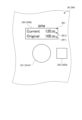
- FIG. 5 is a diagram showing an example of display contents of the first display section 344A in the ratio display mode.
- the ratio display mode is a display mode in which the first display unit 344A displays the first original BPM and the ratio of the first adjusted BPM to the first original BPM (first adjusted ratio), as shown in FIG. be. That is, in the ratio display mode, the display control unit 58 causes the first display unit 344A to display the first original BPM and the first post-adjustment ratio. Therefore, the screen DP2 displayed on the first display portion 344A in the ratio display mode is provided with an original BPM display portion DP11 and a ratio display portion DP22 for displaying the first adjusted ratio.
- the ratio displayed in the ratio display mode is an example of information indicating the ratio of the BPM of the song after the playback speed adjustment to the BPM specific to the song.
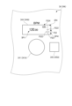
- FIG. 6 is a diagram showing an example of display contents of the first display section 344A in the graphics display mode.
- the graphics display mode is a display mode in which the first display unit 344A displays the first original BPM and one of the graphics FG1 and FG2, as shown in FIG. Figures FG1 and FG2 are figures according to the result of comparison between the first original BPM and the first adjusted BPM. More specifically, the figures FG1 and FG2 are figures showing the magnitude relationship between the first original BPM and the first adjusted BPM, the figure FG1 being an upward triangle and the figure FG2 being a downward triangle. Therefore, the screen DP3 displayed on the first display section 344A in the graphic display mode is provided with an original BPM display section DP11 and a graphic display section DP31 for displaying the graphics FG1 and FG2.
- FIG. 7 is a diagram for explaining the relationship between the first post-adjustment ratio and the displayed graphics FG1 and FG2.
- the display control unit 58 causes the first display unit 344A to display the graphic FG1 and not display the graphic FG2, as shown in FIG. . That is, the graphic FG1 is a graphic indicating that the first adjusted BPM is greater than the first original BPM.
- the display control unit 58 makes the brightness of the graphic FG1 displayed on the first display unit 344A the lowest.
- the first threshold is a value greater than 100%, and is 110% in this embodiment. However, the first threshold can be changed as appropriate.
- the display control unit 58 increases the brightness of the graphic FG1 displayed on the first display unit 344A. That is, the brightness of the graphic FG1 displayed when the first post-adjustment ratio is greater than or equal to the first threshold and less than the second threshold is displayed when the first post-adjustment ratio is greater than 100% and less than the first threshold. higher than the brightness of the figure FG1 to be displayed.
- the second threshold is a value larger than the first threshold, and in this embodiment, the second threshold is 120%. However, the second threshold can be changed as appropriate.
- the display control unit 58 maximizes the brightness of the graphic FG1 displayed on the first display unit 344A. That is, the brightness of the graphic FG1 displayed when the first post-adjustment ratio is greater than 100% increases as the difference between the first original BPM and the first post-adjustment BPM increases. It becomes lower as the difference from the BPM after 1 adjustment becomes smaller. In other words, the brightness of the graphic FG1 decreases as the first adjusted BPM approaches the first original BPM, and increases as the first adjusted BPM separates from the first original BPM.
- Such a difference in luminance of the graphic FG1 is an example of information indicating the ratio of the BPM of the song after the playback speed adjustment to the BPM specific to the song.
- the display control unit 58 causes the first display unit 344A to display the downward triangular graphic FG2 and the upward triangular graphic FG1. is not displayed. That is, the graphic FG2 is a graphic showing that the first adjusted BPM is smaller than the first original BPM.
- the display control unit 58 sets the brightness of the graphic FG2 to the lowest.
- the third threshold is a value smaller than 100%, and is 90% in this embodiment. However, the third threshold can be changed as appropriate.
- the display control unit 58 increases the brightness of the graphic FG2. That is, the luminance of the graphic FG2 displayed when the first post-adjustment ratio is greater than the fourth threshold and equal to or less than the third threshold is such that the first post-adjustment ratio is greater than the third threshold and less than 100%. is higher than the brightness of the graphic FG2 displayed in the case.
- the fourth threshold is a value smaller than the third threshold, and is 80% in this embodiment. However, the fourth threshold can be changed as appropriate.
- the display control unit 58 sets the brightness of the graphic FG2 to the highest. That is, the luminance of the graphic FG2 displayed when the first post-adjustment ratio is less than 100% increases as the difference between the first original BPM and the first post-adjustment BPM increases. It becomes lower as the difference from the BPM after 1 adjustment becomes smaller. In other words, the brightness of the graphic FG2 decreases as the first adjusted BPM approaches the first original BPM, and increases as the first adjusted BPM separates from the first original BPM.
- Such a difference in brightness of the graphic FG2 is an example of information indicating the ratio of the BPM of the song after the playback speed adjustment to the BPM specific to the song.
- the graphics FG1 and FG2 are not displayed as shown in FIG.
- the user can determine the first BPM for the first original BPM.
- the magnitude of the post-adjustment BPM can be intuitively grasped.
- the first post-adjustment ratio can be intuitively grasped.
- the brightness of the graphics FG1 and FG2 increases as the difference between the original BPM and the adjusted BPM increases.
- the brightness of the graphics FG1 and FG2 decreases as the adjusted BPM approaches the original BPM. This makes it easier for the user to grasp that the adjusted BPM is a value that is different from the original BPM.
- the brightness of the graphics FG1 and FG2 may increase as the difference between the original BPM and the adjusted BPM decreases, and decrease as the difference between the original BPM and the adjusted BPM increases.
- the luminance of the graphic FG1 displayed when the first post-adjustment ratio is greater than 100% is maximized when the first post-adjustment ratio is smaller than the first threshold, It may be the lowest when it is equal to or greater than the second threshold.
- the brightness of the graphic FG2 displayed when the first post-adjustment ratio is less than 100% is maximized when the first post-adjustment ratio is greater than the third threshold, and when the first post-adjustment ratio is the third It may be the lowest if it is equal to or less than 4 thresholds.
- the figure FG1 or the figure FG2 appears with high luminance. Since it is displayed, the user can easily determine whether or not the first original BPM and the first adjusted BPM match.
- FIG. 8 is a diagram showing an example of the content displayed by the first display section 344A in the slider display mode.
- the first display unit 344A displays a graphic FG3 as a graphic corresponding to the result of comparison between the first original BPM and the first adjusted BPM. mode.
- a graphic FG3 is a graphic corresponding to the comparison result between the first original BPM and the first adjusted BPM. More specifically, the graphic FG3 is a graphic showing the magnitude relationship between the first original BPM and the first post-adjustment BPM.
- a screen DP4 displayed on the first display portion 344A in the slider display mode is provided with an original BPM display portion DP11 and a graphic display portion DP41 for displaying a graphic FG3.
- the slide operator FG33 slides up and down along the first reference line FG31 to indicate the first post-adjustment ratio.
- the first post-adjustment ratio is 100%, that is, when the first original BPM and the first post-adjustment BPM are the same value
- the slide operator FG33 is moved by the display control unit 58 to the second reference line FG32. placed above.
- the display control unit 58 arranges the slide operator FG33 above the second reference line FG32.
- the display control unit 58 arranges the slide operator FG33 below the second reference line FG32.
- the position of the slide operator FG33 with respect to the second reference line FG32 indicates the magnitude relationship between the first original BPM and the first adjusted BPM.
- the graphic FG3 is a graphic showing the magnitude relationship between the first original BPM and the first adjusted BPM, as described above.
- the range display portion FG34 displays the range of the first post-adjustment ratio indicated by the slide operator FG33 slidably arranged on the first reference line FG31.
- the range of the first post-adjustment ratio indicated by the slide operator FG33 arranged on the first reference line FG31 is changed according to the first post-adjustment ratio. That is, the minimum value defined by the upper end of the first reference line FG31 and the maximum value defined by the lower end of the first reference line FG31 are changed according to the first post-adjustment ratio.
- the display control unit 58 Let the range of the first post-adjustment ratio defined by the first reference line FG31 be the range of 90% or more and 110% or less. At this time, the minimum value defined by the upper end of the first reference line FG31 is 90%, and the maximum value defined by the lower end of the first reference line FG31 is 110%. In this case, "10%" is displayed in the range display portion FG34.
- the display control unit 58 Let the range of the first post-adjustment ratio defined by the first reference line FG31 be the range of 84% or more and 116% or less. At this time, the minimum value defined by the upper end of the first reference line FG31 is 84%, and the maximum value defined by the lower end of the first reference line FG31 is 116%. In this case, "16%" is displayed in the range display portion FG34.
- the display control unit 58 When the first post-adjustment ratio is a value within the range of 0% or more and less than 84%, or a value within the range of 116% or more and 200% or less, the display control unit 58 Let the range of the first post-adjustment ratio defined by the first reference line FG31 be the range of 0% or more and 200% or less. At this time, the minimum value defined by the upper end of the first reference line FG31 is 0%, and the maximum value defined by the lower end of the first reference line FG31 is 200%. In this case, "100%" is displayed in the range display portion FG34. Note that when the first post-adjustment ratio is greater than 200%, the display control unit 58 may display a graphic indicating an error on the graphic display unit DP41 instead of the graphic FG3.
- the information indicated by the graphic FG3 is an example of information indicating the ratio of the BPM of the song after the playback speed adjustment to the BPM specific to the song.
- the first adjustment unit 52 changes the amount of change in the reproduction speed of the first music piece for each unit rotation angle of the first dial 341A according to the rotation state of the first dial 341A.
- the second adjustment unit 55 changes the amount of change in the reproduction speed of the second music piece for each unit rotation angle of the second dial 341B according to the rotation state of the second dial 341B. More specifically, the first adjuster 52 changes the amount of change in the BPM of the first song for each unit rotation angle of the first dial 341A according to the rotation state of the first dial 341A.
- the second adjuster 55 changes the amount of change in the BPM of the second song for each unit rotation angle of the second dial 341B according to the rotation state of the second dial 341B.
- the rotation state of the first dial 341A by changing the rotation state of the first dial 341A, it is possible to change the amount of change in the music playback speed for each unit rotation angle of the first dial 341A. That is, the amount of change can be changed by changing the manner in which the first dial 341A is rotated. Therefore, even if the rotation angle of the first dial 341A is the same, it is possible to switch between a case where the reproduction speed of the first music is greatly changed and a case where the reproduction speed of the first music is slightly changed. Therefore, the playback speed of the first music can be easily adjusted without pressing the SHIFT button or the like, and the convenience of the sound control device 1 can be enhanced.
- the second dial 341B and the second adjusting section 55 is the same.
- the first adjustment unit 52 of the control unit 5 adjusts the amount of change in the BPM of the first song for each unit rotation angle of the first dial 341A while the rotation speed of the first dial 341A is less than the predetermined speed. is the first amount of change. Further, the first adjustment unit 52 of the control unit 5 adjusts the amount of change in the BPM of the first song for each unit rotation angle of the first dial 341A while the rotation speed of the first dial 341A is equal to or higher than the predetermined speed. A second amount of change larger than the amount of change is used. The same applies to the second adjusting section 55 of the control section 5 .
- the first adjustment section 52 of the control section 5 increases the BPM of the first music piece, thereby increasing the playback speed of the first music piece. .
- the first adjustment section 52 of the control section 5 reduces the BPM of the first music, thereby reducing the playback speed of the first music.
- Clockwise rotation corresponds to the first rotation direction
- counterclockwise rotation corresponds to the direction opposite to the first rotation direction.
- the second adjustment section 55B of the control section 5 According to such a configuration, the playback speed of the first music can be increased or decreased according to the rotation direction of the first dial 341A. Therefore, the reproduction speed of the first music can be easily adjusted, and the convenience of the sound control device 1 can be enhanced. A similar effect can be obtained by the second adjusting section 55 as well.
- the acoustic control device 1 includes the housing 2 in which the first dial 341A is rotatably provided on the top surface 21 .
- the first rotation direction is the clockwise direction when viewed from the position facing the top surface 21 .
- the top surface 21 corresponds to the first surface.
- the dial is operated clockwise to increase the numerical value of a predetermined index, and the dial is operated counterclockwise to decrease the numerical value.
- the first dial 341A clockwise, the playback speed of the first song can be increased, and by rotating the first dial 341A counterclockwise, the playback speed of the first song can be increased. can be reduced.
- the sound control device 1 includes a first notification section 343A and a second notification section 343B.
- the first notification unit 343A reaches one of the limit values.
- the second notification section 343B corresponds to the notification section
- the first limit value and the second limit value correspond to the predetermined values. According to such a configuration, even when the user rotates the dial, the user can grasp that the ratio has reached the first limit value or the second limit value. Therefore, the convenience of the acoustic control device 1 can be enhanced.
- the first notification unit 343A Rotation of the first dial 341A in the direction in which the 1 dial 341A was rotated is restricted. That is, the first notification unit 343A rotates the first dial 341A in one of the clockwise and counterclockwise directions, and the ratio of the BPM of the song after the playback speed adjustment to the BPM specific to the first song is set to a predetermined ratio. When the value is reached, rotation of the first dial 341A in the one direction is restricted.
- the first notification unit 343A notifies that the first post-adjustment ratio has reached the first limit value or the second limit value.
- the second notification section 343B According to such a configuration, it is possible for the user to easily grasp that the ratio has reached the first limit value or the second limit value. Therefore, the convenience of the acoustic control device 1 can be further enhanced.
- the acoustic control device 1 includes a first display section 344A and a second display section 344B.
- 344 A of 1st display parts display the information regarding the reproduction speed of the 1st music adjusted by the control part 5.
- the second display section 344B displays information about the playback speed of the second music adjusted by the control section 5.
- FIG. According to such a configuration, it is possible to easily adjust the playback speed of the first music piece and the second music piece by confirming the display contents of the first display section 344A and the second display section 344B.
- the first display unit 344A displays, as information about the reproduction speed of the first music piece adjusted by the first adjustment unit 52 of the control unit 5, the BPM specific to the first music piece after adjusting the reproduction speed.
- Information indicating the BPM ratio of one piece of music is displayed. That is, the first display unit 344A displays information indicating the first post-adjustment ratio, which is the ratio of the first post-adjustment BPM to the first original BPM, as information on the playback speed of the first music piece after the playback speed adjustment.
- the second display section 344B According to such a configuration, the user can intuitively grasp how much the current first adjusted BPM has been adjusted with respect to the first original BPM. Therefore, it is possible to easily adjust the playback speed of the first music piece. A similar effect can be obtained by the second display section 344B.
- the present invention is not limited to this, and at least one of the brightness, color, and flashing cycle of the graphics FG1 and FG2 may be changed according to the first post-adjustment ratio.
- the display control unit 58 sets the color of the graphic FG2 to bluish green.
- the display control unit 58 sets the color of the graphic FG2 to blue.
- the display control unit 58 sets the color of the graphic FG2 to bluish purple. Note that when the first adjusted BPM is the same as the first original BPM, the graphics FG1 and FG2 are not displayed in the same manner as described above.
- the blinking period of the graphics FG1 and FG2 decreases and the blinking frequency of the graphics FG1 and FG2 increases.
- the difference between the original BPM and the adjusted BPM becomes smaller, the blinking period of the graphics FG1 and FG2 increases and the blinking frequency of the graphics FG1 and FG2 decreases.
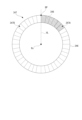
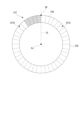
- the ratio display section 347 displays the adjusted ratio under the control of the display control section 58 .
- the ratio display section 347 is composed of a plurality of light emitting elements 348 arranged along the rotation direction of the dial 346 .
- the ratio display portion 347 includes a first region 347A that is half a clockwise region from the base point BP provided in the circumferential direction of the dial 346, and a second region 347B that is a half counterclockwise region from the base point BP. and
- the first area 347A is an area for displaying the post-adjustment ratio when the post-adjustment BPM is greater than the original BPM.
- the post-adjustment ratio is displayed by lighting the same number of light-emitting elements 348 from the base point BP. For example, when the post-adjustment ratio is 130%, the display control unit 58, as shown in FIG. The post-adjustment ratio is displayed on the ratio display section 347 by lighting the number of light emitting elements 348 corresponding to 30% from the base point BP.
- one of the clockwise first region 347A and the counterclockwise second region 347B displays the post-adjustment ratio centering on the base point BP, so that the user can intuitively see the post-adjustment ratio. I can grasp it.
- the luminescent color of the light emitting element 348 arranged in the first region 347A and the luminescent color of the light emitting element 348 arranged in the second region 347B may be different.
- the light-emitting elements 348 that are lit when the adjusted BPM is greater than the original BPM are lit in red among the warm colors
- the light-emitting elements 348 that are lit when the adjusted BPM is less than the original BPM are lit in cool colors. Of these, blue may be lit.
- the process of calculating the position of the base point BP on the rotated dial 346 can be omitted.
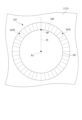
- FIG. 15 is a schematic diagram showing an acoustic control device 1A that is a modification of the acoustic control device 1.
- the playback speed operation section 34 is provided for each channel operation section 3 .
- one reproduction speed operation unit 34 may be provided for the entire sound control device, such as the sound control device 1A shown in FIG. 15, for example.
- the control unit 5 simultaneously adjusts the reproduction speeds of songs on all channels according to the operation on the reproduction speed operation unit 34 .
- the control unit 5 may increase or decrease the BPM during reproduction of music on all channels by the same value in accordance with the rotation state of one reproduction speed operation unit 34. may be increased or decreased at the same rate.
- the amount of change in the reproduction speed of the music for each unit rotation angle may be changed.
- the dials 341 and 346 are rotated by a predetermined angle in one of clockwise and counterclockwise directions, and then rotated by a predetermined angle in the other direction, the control unit 5 is further rotated in one direction.
- the control unit 5 determines whether the dials 341 and 346 are rotated toward the housing 2 without being pressed down, or when the dials 341 and 346 are rotated toward the housing 2 while being pressed down. It is also possible to change the amount of change in BPM of music for each unit rotation angle of 341 and 346 and the amount of change in playback speed of music for each unit rotation angle.
- the control unit 5 sets the amount of change in the BPM of the song for each unit rotation angle of the dials 341, 346 as the first amount of change while the rotation speed of the dials 341, 346 is less than the predetermined speed, While the rotation speed of the dials 341, 346 is equal to or higher than the predetermined speed, the BPM of the music for each unit rotation angle of the dials 341, 346 is set to the second amount of change larger than the first amount of change.
- the second amount of change may be a smaller amount of change than the first amount of change.
- the control unit 5 increases the BPM and playback speed of the music, and rotates the dials 341 and 346 in the first rotation direction. is rotated in the opposite direction, counterclockwise, to decrease the BPM and playback speed of the song.
- the present invention is not limited to this, and the control unit 5 increases the BPM and playback speed of the music when the dials 341 and 346 are rotated counterclockwise, and increases the music playback speed when the dials 341 and 346 are rotated clockwise. BPM and playback speed may be reduced.
- the control unit 5 may be configured to increase or decrease the BPM and playback speed of the music only when the dials 341 and 346 are rotated in one of the clockwise and counterclockwise directions.
- the display unit 344 displays, as information about the music reproduction speed adjusted by the control unit 5, information indicating the ratio of the BPM of the music after the reproduction speed adjustment to the BPM specific to the music.
- the display unit 344 is not limited to this and may display other information.
- the display unit 344 may display the original BPM and the adjusted BPM.
- the brightness of the figures FG1 and FG2 is assumed to differ according to the ratio of the BPM after adjustment to the original BPM (ratio after adjustment).
- the brightness of the graphics FG1 and FG2 may be constant regardless of the post-adjustment ratio.
- the colors and blinking periods of the graphics FG1 and FG2 may be constant regardless of the post-adjustment ratio.
- graphics may be displayed by combining at least two of brightness, color, and blinking cycle.
- the post-adjustment ratio range indicated by the first reference line FG31 that defines the slide range in which the slide operator FG33 can slide is different according to the post-adjustment ratio.
- the range of post-adjustment ratio indicated by the slide range is not limited to this, and may be constant.
- the acoustic control device 1, 1A is provided with the display section 344 that displays the graphics FG1, FG2, FG3, and the like.
- the display unit 344 may not necessarily be provided.
- an external device connected to the sound control device may have a display section for displaying graphics or the like.
- the light-emitting element 348 that constitutes the ratio display portion 347 is provided over one circumference of the dial 346 in the rotation direction of the dial 346 .
- the range in which the light emitting element 348 is provided is not limited to this, and can be changed as appropriate. The same applies when the light-emitting element 348 is provided around the dial 346 .
- the display modes of the display section 344 provided in each channel operation section 3 include direct display mode, ratio display mode, figure display mode, and slider display mode.
- the acoustic control device does not necessarily have to be configured to be able to set all of these display modes.
- the sound control device may have at least one of the graphic display mode and the slider display mode as switchable display modes.
- An acoustic control device capable of adjusting the playback speed of a song, comprising: a rotatably provided dial for accepting an operation for adjusting the playback speed of the song; and a control unit that changes an amount of change in the reproduction speed of the music piece for each unit rotation angle.
- a control unit that changes an amount of change in the reproduction speed of the music piece for each unit rotation angle.
- the control unit adjusts the amount of change in the BPM of the song for each unit rotation angle of the dial while the rotation speed of the dial is less than a predetermined speed. 1 change amount, and while the rotation speed of the dial is equal to or higher than the predetermined speed, the change amount of the BPM of the song for each unit rotation angle of the dial may be set as a second change amount larger than the first change amount. good. According to such a configuration, the amount of change in the BPM of the song for each unit rotation angle of the dial can be switched between the first amount of change and the second amount of change according to the rotational speed of the dial.
- a housing having the dial rotatably provided on a first surface is provided, and the first rotation direction is a clock It may be in a circular direction.
- the dial is operated clockwise to increase the numerical value of a predetermined index, and the dial is operated counterclockwise to decrease the numerical value.
- the playback speed of music can be increased by rotating the dial clockwise, and the playback speed of music can be decreased by rotating the dial counterclockwise. can be done. Therefore, it is possible for the user to easily grasp the operation direction of the dial when increasing or decreasing the reproduction speed of the music, so that it is possible to easily perform the adjustment operation of the reproduction speed of the music.
- the display unit displays, as information about the reproduction speed of the music piece adjusted by the control unit, Information indicating the rate of BPM may be displayed. According to such a configuration, the user can intuitively grasp how much the playback speed specific to the music has been adjusted. Therefore, it is possible to easily adjust the playback speed of the music.
Abstract
An acoustic control device (1) capable of adjusting the playback speed of a song comprises: a dial (341, 346) that is rotatably provided, and receives an operation for adjusting the playback speed of a song; and a control unit (5) that changes the change amount of the playback speed of the song for each unit rotation angle of the dial (341, 346) according to the rotation status of the dial (341, 346).
Description
本発明は、音響制御装置に関する。
The present invention relates to an acoustic control device.
従来、楽曲の再生速度を調節可能な音響制御装置が知られている(例えば非特許文献1参照)。
非特許文献1に記載の音響制御装置は、回転可能に設けられたエンコーダーと、を備え、エンコーダーの回転に応じて、楽曲の再生速度を調節可能である。音響制御装置では、エンコーダーが時計回りに回転されると、楽曲の再生速度に対応するテンポが小数点以下の単位で上がる。一方、エンコーダーが反時計回りに回転されると、テンポが小数点以下の単位で下げられる。また、音響制御装置は、SHIFTボタンを備えており、SHIFTボタンが押下された状態にてエンコーダーが時計回りに回転されると、テンポが小数点よりも上の単位で上げられる。一方、SHIFTボタンが押下された状態にてエンコーダーが反時計回りに回転されると、テンポが小数点よりも上の単位で下げられる。 2. Description of the Related Art Conventionally, a sound control device capable of adjusting the playback speed of music is known (see Non-PatentDocument 1, for example).
The sound control device described in Non-PatentDocument 1 includes a rotatable encoder, and can adjust the playback speed of music according to the rotation of the encoder. In the sound control device, when the encoder is rotated clockwise, the tempo, which corresponds to the playback speed of the song, increases in decimal places. On the other hand, when the encoder is rotated counter-clockwise, the tempo is decreased in decimal places. The sound control device also has a SHIFT button, and when the SHIFT button is pressed and the encoder is rotated clockwise, the tempo is increased in units above the decimal point. On the other hand, when the SHIFT button is pressed and the encoder is rotated counterclockwise, the tempo is decreased in units above the decimal point.
非特許文献1に記載の音響制御装置は、回転可能に設けられたエンコーダーと、を備え、エンコーダーの回転に応じて、楽曲の再生速度を調節可能である。音響制御装置では、エンコーダーが時計回りに回転されると、楽曲の再生速度に対応するテンポが小数点以下の単位で上がる。一方、エンコーダーが反時計回りに回転されると、テンポが小数点以下の単位で下げられる。また、音響制御装置は、SHIFTボタンを備えており、SHIFTボタンが押下された状態にてエンコーダーが時計回りに回転されると、テンポが小数点よりも上の単位で上げられる。一方、SHIFTボタンが押下された状態にてエンコーダーが反時計回りに回転されると、テンポが小数点よりも上の単位で下げられる。 2. Description of the Related Art Conventionally, a sound control device capable of adjusting the playback speed of music is known (see Non-Patent
The sound control device described in Non-Patent
しかしながら、非特許文献1に記載の構成では、楽曲の再生速度を大きく変更する場合に、SHIFTボタンを押下しつつエンコーダーを回転させる必要がある。このため、楽曲の再生速度を調節する操作が煩雑であるという問題がある。
However, with the configuration described in Non-Patent Document 1, it is necessary to rotate the encoder while pressing the SHIFT button when greatly changing the playback speed of the music. Therefore, there is a problem that the operation for adjusting the playback speed of music is complicated.
本発明の一態様に係る音響制御装置は、楽曲の再生速度を調節可能な音響制御装置であって、回転可能に設けられ、前記楽曲の再生速度を調節する操作を受け付けるダイヤルと、前記ダイヤルの回転状態に応じて、前記ダイヤルの単位回転角度毎の前記楽曲の再生速度の変化量を変化させる制御部と、を備える。
A sound control device according to an aspect of the present invention is a sound control device capable of adjusting the playback speed of a piece of music, comprising: a dial provided rotatably for receiving an operation for adjusting the playback speed of the piece of music; and a control unit that changes an amount of change in the reproduction speed of the music piece for each unit rotation angle of the dial according to the rotation state.
[第1実施形態]
以下、本発明の第1実施形態を、図面に基づいて説明する。
[音響制御装置の概略構成]
図1は、本実施形態に係る音響制御装置1の構成を示す模式図である。
本実施形態に係る音響制御装置1は、入力する楽曲の再生速度を調節可能に構成されている。具体的に、音響制御装置1は、楽曲のBPM(Beats Per Minute)を調節することによって、楽曲の再生速度を調節する。なお、楽曲のBPMとは、楽曲再生時のテンポ、すなわち、楽曲再生時の1分間の拍数を表している。本実施形態では、音響制御装置1は、第1チャンネルにロードされた第1楽曲の再生、及び、第2チャンネルにロードされた第2楽曲の再生を個別に制御し、第1チャンネルにて再生された第1楽曲、及び、第2チャンネルにて再生された第2楽曲をミックスし、ミックスした楽曲に応じた音声信号を出力するミキサーである。
音響制御装置1は、図1に示すように、筐体2と、2つのチャンネル操作部3(3A,3B)と、クロスフェーダー4と、を備える。また、図1では図示を省略するが、音響制御装置1は、音響制御装置1の動作を制御する制御部5(図2参照)を備える。 [First embodiment]
A first embodiment of the present invention will be described below with reference to the drawings.
[Schematic configuration of acoustic control device]
FIG. 1 is a schematic diagram showing the configuration of anacoustic control device 1 according to this embodiment.
Thesound control device 1 according to this embodiment is configured to be able to adjust the playback speed of the input music. Specifically, the sound control device 1 adjusts the playback speed of the music by adjusting the BPM (Beats Per Minute) of the music. It should be noted that the BPM of a piece of music represents the tempo during reproduction of the piece of music, that is, the number of beats per minute during reproduction of the piece of music. In this embodiment, the sound control device 1 individually controls the reproduction of the first music loaded on the first channel and the reproduction of the second music loaded on the second channel, and reproduces the music on the first channel. The mixer mixes the first music played on the second channel and the second music reproduced on the second channel, and outputs an audio signal corresponding to the mixed music.
Thesound control device 1 includes a housing 2, two channel operation units 3 (3A and 3B), and a crossfader 4, as shown in FIG. Although not shown in FIG. 1, the sound control device 1 includes a control section 5 (see FIG. 2) that controls the operation of the sound control device 1. As shown in FIG.
以下、本発明の第1実施形態を、図面に基づいて説明する。
[音響制御装置の概略構成]
図1は、本実施形態に係る音響制御装置1の構成を示す模式図である。
本実施形態に係る音響制御装置1は、入力する楽曲の再生速度を調節可能に構成されている。具体的に、音響制御装置1は、楽曲のBPM(Beats Per Minute)を調節することによって、楽曲の再生速度を調節する。なお、楽曲のBPMとは、楽曲再生時のテンポ、すなわち、楽曲再生時の1分間の拍数を表している。本実施形態では、音響制御装置1は、第1チャンネルにロードされた第1楽曲の再生、及び、第2チャンネルにロードされた第2楽曲の再生を個別に制御し、第1チャンネルにて再生された第1楽曲、及び、第2チャンネルにて再生された第2楽曲をミックスし、ミックスした楽曲に応じた音声信号を出力するミキサーである。
音響制御装置1は、図1に示すように、筐体2と、2つのチャンネル操作部3(3A,3B)と、クロスフェーダー4と、を備える。また、図1では図示を省略するが、音響制御装置1は、音響制御装置1の動作を制御する制御部5(図2参照)を備える。 [First embodiment]
A first embodiment of the present invention will be described below with reference to the drawings.
[Schematic configuration of acoustic control device]
FIG. 1 is a schematic diagram showing the configuration of an
The
The
[筐体の構成]
筐体2は、略直方体形状に形成され、制御部5を内部に収容する。筐体2は、天面21、上面22、下面23、左側面24、右側面25、及び、図示しない底面を有する。
天面21には、2つのチャンネル操作部3(3A,3B)と、クロスフェーダー4と、が配置される。 [Case configuration]
Thehousing 2 is formed in a substantially rectangular parallelepiped shape and accommodates the controller 5 inside. The housing 2 has a top surface 21, an upper surface 22, a lower surface 23, a left side surface 24, a right side surface 25, and a bottom surface (not shown).
Two channel operation units 3 ( 3 A, 3 B) and acrossfader 4 are arranged on the top surface 21 .
筐体2は、略直方体形状に形成され、制御部5を内部に収容する。筐体2は、天面21、上面22、下面23、左側面24、右側面25、及び、図示しない底面を有する。
天面21には、2つのチャンネル操作部3(3A,3B)と、クロスフェーダー4と、が配置される。 [Case configuration]
The
Two channel operation units 3 ( 3 A, 3 B) and a
[チャンネル操作部の構成]
2つのチャンネル操作部3(3A,3B)は、対応するチャンネルにロードされた楽曲の再生状態を操作する。2つのチャンネル操作部3は、第1チャンネルにロードされた第1楽曲の再生状態を操作する第1チャンネル操作部3A、及び、第2チャンネルにロードされた第2楽曲の再生状態を操作する第2チャンネル操作部3Bである。
各チャンネル操作部3は、ジョグダイヤル31、イコライザー調節部32、チャンネルフェーダー33及び再生速度操作部34を有する。 [Configuration of channel operation section]
The two channel operation units 3 (3A, 3B) operate the playback state of the music loaded to the corresponding channels. The twochannel operation units 3 are a first channel operation unit 3A for operating the playback state of the first music loaded on the first channel, and a second channel operation unit 3A for operating the playback state of the second music loaded on the second channel. This is the 2-channel operation section 3B.
Eachchannel operation section 3 has a jog dial 31 , an equalizer adjustment section 32 , a channel fader 33 and a playback speed operation section 34 .
2つのチャンネル操作部3(3A,3B)は、対応するチャンネルにロードされた楽曲の再生状態を操作する。2つのチャンネル操作部3は、第1チャンネルにロードされた第1楽曲の再生状態を操作する第1チャンネル操作部3A、及び、第2チャンネルにロードされた第2楽曲の再生状態を操作する第2チャンネル操作部3Bである。
各チャンネル操作部3は、ジョグダイヤル31、イコライザー調節部32、チャンネルフェーダー33及び再生速度操作部34を有する。 [Configuration of channel operation section]
The two channel operation units 3 (3A, 3B) operate the playback state of the music loaded to the corresponding channels. The two
Each
ジョグダイヤル31は、回転可能に天面21に設けられ、再生中の楽曲の再生方向及び再生速度を調節する際に用いられるダイヤルである。なお、ユーザーがジョグダイヤル31の回転方向の変更と回転速度の変更とを組み合わせることにより、DJパフォーマンス特有のスクラッチ操作が行われる。
The jog dial 31 is a dial that is rotatably provided on the top surface 21 and used to adjust the playback direction and playback speed of the song being played. It should be noted that when the user combines the change of the rotation direction and the change of the rotation speed of the jog dial 31, a scratch operation peculiar to the DJ performance is performed.
イコライザー調節部32は、対応するチャンネルのイコライザー調節処理を行う。イコライザー調節部32は、レベル調節部321、高周波帯域調節部322、中周波帯域調節部323、低周波帯域調節部324、エフェクト調節部325を有する。
レベル調節部321は、入力される楽曲の入力レベルを調節する。
高周波帯域調節部322は、入力される楽曲の高周波帯域の音量を調節する。高周波帯域は、例えば4649Hz以上の周波数帯域である。
中周波帯域調節部323は、入力される楽曲の中周波帯域の音量を調整する。中周波帯域は、例えば284Hzを超え、4649Hz未満の周波数帯域である。
低周波帯域調節部324は、入力される楽曲の低周波帯域の音量を調整する。低周波帯域は、例えば284Hz以下の周波数帯域である。
エフェクト調節部325は、対応するチャンネル操作部3に設定されたエフェクトのエフェクト量を調節する。
チャンネルフェーダー33は、対応するチャンネル操作部3から出力される音量を調整する。 Theequalizer adjustment unit 32 performs equalizer adjustment processing for the corresponding channel. The equalizer adjustment section 32 has a level adjustment section 321 , a high frequency band adjustment section 322 , an intermediate frequency band adjustment section 323 , a low frequency band adjustment section 324 and an effect adjustment section 325 .
Thelevel adjustment section 321 adjusts the input level of the input music.
The high frequencyband adjustment unit 322 adjusts the volume of the high frequency band of the input music. A high frequency band is, for example, a frequency band of 4649 Hz or higher.
The medium frequencyband adjustment unit 323 adjusts the volume of the medium frequency band of the input music. The medium frequency band is, for example, a frequency band above 284 Hz and below 4649 Hz.
The low frequencyband adjustment unit 324 adjusts the volume of the low frequency band of the input music. The low frequency band is, for example, a frequency band of 284 Hz or less.
Theeffect adjustment section 325 adjusts the amount of effect set in the corresponding channel operation section 3 .
Thechannel fader 33 adjusts the volume output from the corresponding channel operation section 3 .
レベル調節部321は、入力される楽曲の入力レベルを調節する。
高周波帯域調節部322は、入力される楽曲の高周波帯域の音量を調節する。高周波帯域は、例えば4649Hz以上の周波数帯域である。
中周波帯域調節部323は、入力される楽曲の中周波帯域の音量を調整する。中周波帯域は、例えば284Hzを超え、4649Hz未満の周波数帯域である。
低周波帯域調節部324は、入力される楽曲の低周波帯域の音量を調整する。低周波帯域は、例えば284Hz以下の周波数帯域である。
エフェクト調節部325は、対応するチャンネル操作部3に設定されたエフェクトのエフェクト量を調節する。
チャンネルフェーダー33は、対応するチャンネル操作部3から出力される音量を調整する。 The
The
The high frequency
The medium frequency
The low frequency
The
The
再生速度操作部34は、対応するチャンネルにロードされた楽曲の再生速度を調節する操作を受け付ける。再生速度操作部34は、ダイヤル341、検出部342、通知部343、表示部344及び切替操作部345を有する。
ダイヤル341は、楽曲の再生速度を調節する操作を受け付ける。ダイヤル341は、天面21に対向する位置から見て時計回り及び反時計回りに回転可能に設けられている。詳述すると、ダイヤル341は、後述する通知部343によって回転の規制が行われるまでの間、何周でも時計回り又は反時計回りに回転可能である。
検出部342は、ダイヤル341の回転状態を検出する。具体的に、検出部342は、ロータリーエンコーダーを有し、ダイヤル341の回転加速度及び回転角を検出する。検出部342は、検出した回転加速度及び回転角を制御部5に出力する。詳しくは後述するが、制御部5は、検出部342の検出結果に基づいて、対応するチャンネルにロードされた楽曲のBPMを調節して、楽曲の再生速度を変更する。 The reproductionspeed operation unit 34 receives an operation for adjusting the reproduction speed of the music loaded on the corresponding channel. The playback speed operation section 34 has a dial 341 , a detection section 342 , a notification section 343 , a display section 344 and a switching operation section 345 .
Thedial 341 accepts an operation for adjusting the playback speed of music. The dial 341 is rotatable clockwise and counterclockwise when viewed from a position facing the top surface 21 . More specifically, the dial 341 can rotate clockwise or counterclockwise any number of times until the rotation is restricted by the notification unit 343, which will be described later.
Adetection unit 342 detects the rotation state of the dial 341 . Specifically, the detection unit 342 has a rotary encoder and detects the rotation acceleration and rotation angle of the dial 341 . The detection unit 342 outputs the detected rotational acceleration and rotation angle to the control unit 5 . Although details will be described later, the control unit 5 adjusts the BPM of the music loaded to the corresponding channel based on the detection result of the detection unit 342 to change the reproduction speed of the music.
ダイヤル341は、楽曲の再生速度を調節する操作を受け付ける。ダイヤル341は、天面21に対向する位置から見て時計回り及び反時計回りに回転可能に設けられている。詳述すると、ダイヤル341は、後述する通知部343によって回転の規制が行われるまでの間、何周でも時計回り又は反時計回りに回転可能である。
検出部342は、ダイヤル341の回転状態を検出する。具体的に、検出部342は、ロータリーエンコーダーを有し、ダイヤル341の回転加速度及び回転角を検出する。検出部342は、検出した回転加速度及び回転角を制御部5に出力する。詳しくは後述するが、制御部5は、検出部342の検出結果に基づいて、対応するチャンネルにロードされた楽曲のBPMを調節して、楽曲の再生速度を変更する。 The reproduction
The
A
通知部343は、後述する制御部5による制御の下、楽曲に固有のBPMに対して再生速度調節後の楽曲のBPMの割合が所定値に到達したことをユーザーに通知する。本実施形態では、通知部343は、ダイヤル341の回転を規制することによって、当該割合が所定値に到達したことをユーザーに通知する。通知部343による通知については、後に詳述する。
表示部344は、制御部5による制御の下、楽曲の再生速度に関する情報を表示する。表示部344による表示内容については、後に詳述する。
切替操作部345は、表示部344による表示内容を切り替える。換言すると、切替操作部345は、表示部344の表示モードを切り替える。表示モードについては、後に詳述する。 Thenotification unit 343, under the control of the control unit 5, which will be described later, notifies the user that the ratio of the BPM of the song after the playback speed adjustment to the BPM specific to the song has reached a predetermined value. In this embodiment, the notification unit 343 notifies the user that the ratio has reached a predetermined value by restricting the rotation of the dial 341 . Notification by the notification unit 343 will be described in detail later.
Thedisplay unit 344 displays information about the playback speed of music under the control of the control unit 5 . The contents displayed by the display unit 344 will be described in detail later.
The switchingoperation section 345 switches the content displayed by the display section 344 . In other words, the switching operation section 345 switches the display mode of the display section 344 . The display mode will be detailed later.
表示部344は、制御部5による制御の下、楽曲の再生速度に関する情報を表示する。表示部344による表示内容については、後に詳述する。
切替操作部345は、表示部344による表示内容を切り替える。換言すると、切替操作部345は、表示部344の表示モードを切り替える。表示モードについては、後に詳述する。 The
The
The switching
以下の説明では、便宜上、第1チャンネル操作部3Aが有する再生速度操作部34、ダイヤル341、検出部342、通知部343、表示部344及び切替操作部345を第1再生速度操作部34A、第1ダイヤル341A、第1検出部342A、第1通知部343A、第1表示部344A及び第1切替操作部345Aとし、第2チャンネル操作部3Bが有する再生速度操作部34、ダイヤル341、検出部342、通知部343、表示部344及び切替操作部345を第2再生速度操作部34B、第2ダイヤル341B、第2検出部342B、第2通知部343B、第2表示部344B及び第2切替操作部345Bとして説明する。
In the following description, for the sake of convenience, the reproduction speed operation section 34, the dial 341, the detection section 342, the notification section 343, the display section 344, and the switching operation section 345 of the first channel operation section 3A will be referred to as the first reproduction speed operation section 34A and the first channel operation section 34A. 1 dial 341A, first detection section 342A, first notification section 343A, first display section 344A and first switching operation section 345A, playback speed operation section 34, dial 341 and detection section 342 of second channel operation section 3B. , the notification unit 343, the display unit 344 and the switching operation unit 345 are replaced by the second reproduction speed operation unit 34B, the second dial 341B, the second detection unit 342B, the second notification unit 343B, the second display unit 344B and the second switching operation unit. 345B.
クロスフェーダー4は、左右に移動可能な操作子41を有する。操作子41が左方に移動されるに従って、音響制御装置1から出力される音量において第1チャンネルの音量の割合が大きくなる。また、操作子41が右方に移動されるに従って、音響制御装置1から出力される音量において第2チャンネルの音量の割合が大きくなる。
The crossfader 4 has an operator 41 that can move left and right. As the operator 41 is moved to the left, the ratio of the volume of the first channel in the volume output from the sound control device 1 increases. Further, as the operator 41 is moved to the right, the ratio of the sound volume of the second channel in the sound volume output from the sound control device 1 increases.
[制御部の構成]
図2は、制御部5の構成を示すブロック図である。
制御部5は、CPU(Central Processing Unit)等の演算処理装置を有する回路基板によって構成されている。制御部5は、上記のように、音響制御装置1の動作を制御する。具体的に、制御部5は、各チャンネルにロードされた楽曲を再生する他、ダイヤル341の操作状態に基づいて楽曲の再生速度を調節する。
制御部5は、図2に示すように、第1再生部51、第1調節部52、第1制御部53、第2再生部54、第2調節部55、第2制御部56、モード切替部57及び表示制御部58を有する。 [Configuration of control unit]
FIG. 2 is a block diagram showing the configuration of thecontrol section 5. As shown in FIG.
Thecontrol unit 5 is configured by a circuit board having an arithmetic processing device such as a CPU (Central Processing Unit). The control unit 5 controls the operation of the acoustic control device 1 as described above. Specifically, the control unit 5 reproduces music loaded on each channel, and also adjusts the reproduction speed of the music based on the operating state of the dial 341 .
As shown in FIG. 2, thecontrol unit 5 includes a first reproduction unit 51, a first adjustment unit 52, a first control unit 53, a second reproduction unit 54, a second adjustment unit 55, a second control unit 56, a mode switching unit, and a mode switching unit. It has a unit 57 and a display control unit 58 .
図2は、制御部5の構成を示すブロック図である。
制御部5は、CPU(Central Processing Unit)等の演算処理装置を有する回路基板によって構成されている。制御部5は、上記のように、音響制御装置1の動作を制御する。具体的に、制御部5は、各チャンネルにロードされた楽曲を再生する他、ダイヤル341の操作状態に基づいて楽曲の再生速度を調節する。
制御部5は、図2に示すように、第1再生部51、第1調節部52、第1制御部53、第2再生部54、第2調節部55、第2制御部56、モード切替部57及び表示制御部58を有する。 [Configuration of control unit]
FIG. 2 is a block diagram showing the configuration of the
The
As shown in FIG. 2, the
第1再生部51は、第1チャンネルにロードされた第1楽曲を再生する。
第1調節部52は、第1楽曲の再生速度を調節する。第1調節部52は、第1チャンネル操作部3Aに対するユーザーの操作に応じて、第1楽曲の再生状態を調節する。例えば、第1調節部52は、第1チャンネル操作部3Aのジョグダイヤル31に対するユーザーの操作に応じて、第1再生部51によって再生されている第1楽曲の再生速度及び再生方向を調節する。
また例えば、第1調節部52は、第1ダイヤル341Aの回転状態を検出する第1検出部342Aによる検出結果に基づいて、第1再生部51によって再生される第1楽曲のBPMを調節して、第1楽曲の再生速度を調節する。なお、第1調節部52による第1楽曲の再生速度の調節方法については、後に詳述する。 Thefirst playback unit 51 plays back the first music loaded on the first channel.
Thefirst adjuster 52 adjusts the playback speed of the first music. The first adjustment unit 52 adjusts the playback state of the first music according to the user's operation on the first channel operation unit 3A. For example, the first adjustment unit 52 adjusts the playback speed and playback direction of the first music played by the first playback unit 51 according to the user's operation on the jog dial 31 of the first channel operation unit 3A.
Also, for example, thefirst adjustment unit 52 adjusts the BPM of the first music reproduced by the first reproduction unit 51 based on the detection result of the first detection unit 342A that detects the rotation state of the first dial 341A. , to adjust the playback speed of the first song. A method of adjusting the playback speed of the first music piece by the first adjustment unit 52 will be described in detail later.
第1調節部52は、第1楽曲の再生速度を調節する。第1調節部52は、第1チャンネル操作部3Aに対するユーザーの操作に応じて、第1楽曲の再生状態を調節する。例えば、第1調節部52は、第1チャンネル操作部3Aのジョグダイヤル31に対するユーザーの操作に応じて、第1再生部51によって再生されている第1楽曲の再生速度及び再生方向を調節する。
また例えば、第1調節部52は、第1ダイヤル341Aの回転状態を検出する第1検出部342Aによる検出結果に基づいて、第1再生部51によって再生される第1楽曲のBPMを調節して、第1楽曲の再生速度を調節する。なお、第1調節部52による第1楽曲の再生速度の調節方法については、後に詳述する。 The
The
Also, for example, the
第1制御部53は、第1再生部51による第1楽曲データの再生、及び、第1楽曲データが再生されて得られる楽曲の出力を制御する。例えば、第1制御部53は、第1調節部52によって調節された再生状態にて、第1再生部51に第1楽曲を再生させる。また、第1制御部53は、第1チャンネル操作部3Aのイコライザー調節部32に対するユーザーの操作に応じて、第1楽曲が第1再生部51によって再生されて得られる楽曲の出力を制御する。更に、第1制御部53は、第1通知部343Aを制御する。第1制御部53による第1通知部343Aの制御については、後に詳述する。
The first control unit 53 controls the reproduction of the first music data by the first reproduction unit 51 and the output of the music obtained by reproducing the first music data. For example, the first control unit 53 causes the first reproduction unit 51 to reproduce the first music in the reproduction state adjusted by the first adjustment unit 52 . Also, the first control unit 53 controls the output of the music obtained by reproducing the first music by the first reproduction unit 51 according to the user's operation on the equalizer adjustment unit 32 of the first channel operation unit 3A. Further, the first control section 53 controls the first notification section 343A. The control of the first notification unit 343A by the first control unit 53 will be detailed later.
第2再生部54は、第2チャンネルにロードされた第2楽曲を再生する。
第2調節部55は、第2楽曲の再生速度を調節する。第2調節部55は、第1調節部52と同様に、第2チャンネル操作部3Bに対するユーザーの操作に応じて、第2楽曲データの再生状態を調節する。例えば、第2調節部55は、第2ダイヤル341Bの回転状態を検出する第2検出部342Bによる検出結果に基づいて、第2再生部54によって再生される第2楽曲のBPMを調節して、第2楽曲の再生速度を調節する。なお、第2調節部55による第1楽曲の再生速度の調節方法については、後に詳述する。
第2制御部56は、第1制御部53と同様に、第2再生部54による第2楽曲の再生、及び、第2楽曲が再生されて得られる楽曲の出力を制御する他、第2通知部343Bを制御する。 Thesecond playback unit 54 plays back the second music loaded on the second channel.
Thesecond adjuster 55 adjusts the playback speed of the second music. Like the first adjustment section 52, the second adjustment section 55 adjusts the reproduction state of the second music data according to the user's operation on the second channel operation section 3B. For example, the second adjustment unit 55 adjusts the BPM of the second music reproduced by the second reproduction unit 54 based on the detection result of the second detection unit 342B that detects the rotation state of the second dial 341B, Adjust the playback speed of the second song. A method of adjusting the playback speed of the first music piece by the second adjusting section 55 will be described in detail later.
Similarly to thefirst control unit 53, the second control unit 56 controls the reproduction of the second music by the second reproduction unit 54 and the output of the music obtained by reproducing the second music. It controls the part 343B.
第2調節部55は、第2楽曲の再生速度を調節する。第2調節部55は、第1調節部52と同様に、第2チャンネル操作部3Bに対するユーザーの操作に応じて、第2楽曲データの再生状態を調節する。例えば、第2調節部55は、第2ダイヤル341Bの回転状態を検出する第2検出部342Bによる検出結果に基づいて、第2再生部54によって再生される第2楽曲のBPMを調節して、第2楽曲の再生速度を調節する。なお、第2調節部55による第1楽曲の再生速度の調節方法については、後に詳述する。
第2制御部56は、第1制御部53と同様に、第2再生部54による第2楽曲の再生、及び、第2楽曲が再生されて得られる楽曲の出力を制御する他、第2通知部343Bを制御する。 The
The
Similarly to the
モード切替部57は、第1切替操作部345Aに対する操作に応じて、第1表示部344Aの表示モードを切り替える。また、モード切替部57は、第2切替操作部345Bに対する操作に応じて、第2表示部344Bの表示モードを切り替える。すなわち、表示モードは、第1チャンネル操作部3A及び第2チャンネル操作部3Bのそれぞれに対して個別に設定される。
モード切替部57によって切り替えられる表示モードについては、後に詳述する。 Themode switching portion 57 switches the display mode of the first display portion 344A according to the operation on the first switching operation portion 345A. Further, the mode switching portion 57 switches the display mode of the second display portion 344B according to the operation on the second switching operation portion 345B. That is, the display mode is individually set for each of the first channel operation section 3A and the second channel operation section 3B.
The display modes switched by themode switching unit 57 will be described in detail later.
モード切替部57によって切り替えられる表示モードについては、後に詳述する。 The
The display modes switched by the
表示制御部58は、第1調節部52によって調節された第1楽曲の再生速度に関する情報を、第1表示部344Aに表示させる。詳述すると、表示制御部58は、第1楽曲の再生速度に対応するBPMに関する情報を、第1表示部344Aに表示させる。また、表示制御部58は、第2調節部55によって調節された第2楽曲の再生速度に関する情報を、第2表示部344Bに表示させる。詳述すると、表示制御部58は、第2楽曲の再生速度に対応するBPMに関する情報を、第2表示部344Bに表示させる。各表示部344A,344Bによる表示内容は、各チャンネル操作部3の表示モードに応じて異なる。表示制御部58によって表示部344に表示される内容については、後に詳述する。
The display control unit 58 causes the first display unit 344A to display information about the playback speed of the first music piece adjusted by the first adjustment unit 52. Specifically, the display control unit 58 causes the first display unit 344A to display information about the BPM corresponding to the playback speed of the first music piece. In addition, the display control unit 58 causes the second display unit 344B to display information about the playback speed of the second music adjusted by the second adjustment unit 55. FIG. Specifically, the display control unit 58 causes the second display unit 344B to display information about the BPM corresponding to the playback speed of the second music. The contents displayed by the display sections 344A and 344B differ according to the display mode of each channel operation section 3. FIG. The contents displayed on the display unit 344 by the display control unit 58 will be described in detail later.
[再生速度の調節]
第1調節部52は、第1検出部342Aによって検出される第1ダイヤル341Aの回転状態に基づいて、第1楽曲の再生速度を調節する。具体的に、第1調節部52は、第1検出部342Aによる検出結果として、第1ダイヤル341Aの回転方向、第1ダイヤル341Aの回転加速度、及び、第1ダイヤル341Aの回転角度を取得する。そして、第1調節部52は、第1ダイヤル341Aの回転加速度に基づいて第1ダイヤル341Aの回転速度を算出し、第1ダイヤル341Aの回転方向、回転速度及び回転角度に基づいて、第1楽曲のBPMを調節して第1楽曲の再生速度を調節する。すなわち、第1調節部52が第1楽曲の再生速度を調節するときに参照する第1ダイヤル341Aの回転状態は、第1ダイヤル341Aの回転速度を含む。 [Adjust playback speed]
Thefirst adjuster 52 adjusts the playback speed of the first music based on the rotation state of the first dial 341A detected by the first detector 342A. Specifically, the first adjustment unit 52 acquires the rotation direction of the first dial 341A, the rotation acceleration of the first dial 341A, and the rotation angle of the first dial 341A as the detection results of the first detection unit 342A. Then, the first adjustment unit 52 calculates the rotation speed of the first dial 341A based on the rotation acceleration of the first dial 341A, and calculates the rotation speed of the first song based on the rotation direction, rotation speed and rotation angle of the first dial 341A. is adjusted to adjust the playback speed of the first music piece. That is, the rotational state of the first dial 341A referred to when the first adjustment unit 52 adjusts the reproduction speed of the first music includes the rotational speed of the first dial 341A.
第1調節部52は、第1検出部342Aによって検出される第1ダイヤル341Aの回転状態に基づいて、第1楽曲の再生速度を調節する。具体的に、第1調節部52は、第1検出部342Aによる検出結果として、第1ダイヤル341Aの回転方向、第1ダイヤル341Aの回転加速度、及び、第1ダイヤル341Aの回転角度を取得する。そして、第1調節部52は、第1ダイヤル341Aの回転加速度に基づいて第1ダイヤル341Aの回転速度を算出し、第1ダイヤル341Aの回転方向、回転速度及び回転角度に基づいて、第1楽曲のBPMを調節して第1楽曲の再生速度を調節する。すなわち、第1調節部52が第1楽曲の再生速度を調節するときに参照する第1ダイヤル341Aの回転状態は、第1ダイヤル341Aの回転速度を含む。 [Adjust playback speed]
The
例えば、第1調節部52は、天面21に対向する位置から見て第1ダイヤル341Aが時計回りに回転されると、第1調節部52は、現在の第1楽曲の再生速度に対応するBPMを増加させて、現在の第1楽曲の再生速度を増加させる。時計回りは、第1回転方向に相当する。
一方、第1調節部52は、天面21に対向する位置から見て第1ダイヤル341Aが反時計回りに回転されると、第1調節部52は、現在の第1楽曲のBPMを減少させて、現在の第1楽曲の再生速度を減少させる。反時計回りは、第1回転方向とは反対方向に相当する。 For example, when thefirst dial 341A is rotated clockwise when viewed from the position facing the top surface 21, the first adjustment unit 52 adjusts the playback speed of the current first music piece. The BPM is increased to increase the playback speed of the current first music piece. Clockwise corresponds to the first rotation direction.
On the other hand, when thefirst dial 341A is rotated counterclockwise when viewed from the position facing the top surface 21, the first adjustment unit 52 decreases the BPM of the current first music piece. to decrease the playback speed of the current first song. Counterclockwise corresponds to a direction opposite to the first rotation direction.
一方、第1調節部52は、天面21に対向する位置から見て第1ダイヤル341Aが反時計回りに回転されると、第1調節部52は、現在の第1楽曲のBPMを減少させて、現在の第1楽曲の再生速度を減少させる。反時計回りは、第1回転方向とは反対方向に相当する。 For example, when the
On the other hand, when the
また、第1調節部52は、第1ダイヤル341Aの回転速度及び回転角度に基づいて、第1楽曲の再生速度を変化させる。
具体的に、第1調節部52は、第1ダイヤル341Aの回転速度が所定速度未満である間、第1ダイヤル341Aの単位回転角度毎の第1楽曲の再生速度の変化量を、第1変化量とする。すなわち、第1調節部52は、第1ダイヤル341Aの回転速度が所定速度未満である間、第1ダイヤル341Aの単位回転角度毎の第1楽曲のBPMの変化量を、第1変化量とする。そして、第1調節部52は、第1ダイヤル341Aの回転速度が所定速度未満である間、第1ダイヤル341Aの回転角度が単位回転角度に達する毎に、現在の第1楽曲のBPMに対して第1変化量を加算又は減算する。
例えば、単位回転角度が3°であり、第1変化量が0.1である場合には、第1ダイヤル341Aの回転速度が所定速度未満である間、第1調節部52は、第1ダイヤル341Aが3°回転される毎に、第1楽曲のBPMを0.1ずつ加算又は減算する。このため、例えば上記所定速度未満の回転速度で第1ダイヤル341Aを時計回りに90°回転させた場合には、第1楽曲のBPMは、第1ダイヤル341Aが時計回りに90°回転される前の第1楽曲のBPMに3を加算した値となる。また例えば、上記所定速度未満の回転速度で第1ダイヤル341Aを反時計回りに30°回転させた場合には、第1楽曲のBPMは、第1ダイヤル341Aが反時計回りに30°回転される前の第1楽曲のBPMに1を減算した値となる。 Also, thefirst adjustment unit 52 changes the playback speed of the first music based on the rotation speed and rotation angle of the first dial 341A.
Specifically, while the rotation speed offirst dial 341A is less than the predetermined speed, first adjustment unit 52 adjusts the amount of change in the playback speed of the first music piece for each unit rotation angle of first dial 341A to the first change. Quantity. That is, while the rotation speed of the first dial 341A is less than the predetermined speed, the first adjustment unit 52 sets the amount of change in the BPM of the first song for each unit rotation angle of the first dial 341A as the first amount of change. . While the rotation speed of the first dial 341A is less than the predetermined speed, the first adjustment unit 52 adjusts the current BPM of the first music every time the rotation angle of the first dial 341A reaches the unit rotation angle. Add or subtract the first change amount.
For example, when the unit rotation angle is 3° and the first change amount is 0.1, while the rotation speed of thefirst dial 341A is less than the predetermined speed, the first adjustment unit 52 rotates the first dial Each time 341A is rotated by 3°, the BPM of the first music is added or subtracted by 0.1. Therefore, for example, when the first dial 341A is rotated 90° clockwise at a rotation speed less than the predetermined speed, the BPM of the first music is 3 is added to the BPM of the first music piece. Further, for example, when the first dial 341A is rotated 30° counterclockwise at a rotational speed lower than the predetermined speed, the BPM of the first music is rotated 30° counterclockwise by the first dial 341A. It is a value obtained by subtracting 1 from the BPM of the previous first music piece.
具体的に、第1調節部52は、第1ダイヤル341Aの回転速度が所定速度未満である間、第1ダイヤル341Aの単位回転角度毎の第1楽曲の再生速度の変化量を、第1変化量とする。すなわち、第1調節部52は、第1ダイヤル341Aの回転速度が所定速度未満である間、第1ダイヤル341Aの単位回転角度毎の第1楽曲のBPMの変化量を、第1変化量とする。そして、第1調節部52は、第1ダイヤル341Aの回転速度が所定速度未満である間、第1ダイヤル341Aの回転角度が単位回転角度に達する毎に、現在の第1楽曲のBPMに対して第1変化量を加算又は減算する。
例えば、単位回転角度が3°であり、第1変化量が0.1である場合には、第1ダイヤル341Aの回転速度が所定速度未満である間、第1調節部52は、第1ダイヤル341Aが3°回転される毎に、第1楽曲のBPMを0.1ずつ加算又は減算する。このため、例えば上記所定速度未満の回転速度で第1ダイヤル341Aを時計回りに90°回転させた場合には、第1楽曲のBPMは、第1ダイヤル341Aが時計回りに90°回転される前の第1楽曲のBPMに3を加算した値となる。また例えば、上記所定速度未満の回転速度で第1ダイヤル341Aを反時計回りに30°回転させた場合には、第1楽曲のBPMは、第1ダイヤル341Aが反時計回りに30°回転される前の第1楽曲のBPMに1を減算した値となる。 Also, the
Specifically, while the rotation speed of
For example, when the unit rotation angle is 3° and the first change amount is 0.1, while the rotation speed of the
また、第1調節部52は、第1ダイヤル341Aの回転速度が所定速度以上である間、第1ダイヤル341Aの単位回転角度毎の第1楽曲の再生速度の変化量を、第1変化量よりも大きい第2変化量とする。すなわち、第1調節部52は、第1ダイヤル341Aの回転速度が所定速度以上である間、第1ダイヤル341Aの単位回転角度毎の第1楽曲のBPMの変化量を、第2変化量とする。そして、第1調節部52は、第1ダイヤル341Aの回転速度が所定速度以上である間、第1ダイヤル341Aの回転角度が単位回転角度に達する毎に、現在の第1楽曲のBPMに対して第2変化量を加算又は減算する。
例えば、単位回転角度が3°であり、第2変化量が1°である場合には、第1ダイヤル341Aの回転速度が所定速度以上である間、第1調節部52は、第1ダイヤル341Aが3°回転される毎に、第1楽曲のBPMを1ずつ加算又は減算する。このため、例えば上記所定速度以上の回転速度で第1ダイヤル341Aを時計回りに90°回転させた場合には、第1楽曲のBPMは、第1ダイヤル341Aが時計回りに90°回転される前の第1楽曲のBPMに30を加算した値となる。また例えば、上記所定速度以上の回転速度で第1ダイヤル341Aを反時計回りに30°回転させた場合には、第1楽曲のBPMは、第1ダイヤル341Aが反時計回りに30°回転される前の第1楽曲のBPMに10を減算した値となる。 Further, while the rotation speed of thefirst dial 341A is equal to or higher than the predetermined speed, the first adjustment unit 52 adjusts the amount of change in the reproduction speed of the first music piece for each unit rotation angle of the first dial 341A from the first amount of change. is also a large second amount of change. That is, while the rotation speed of the first dial 341A is equal to or higher than the predetermined speed, the first adjustment unit 52 sets the amount of change in the BPM of the first song for each unit rotation angle of the first dial 341A as the second amount of change. . While the rotation speed of the first dial 341A is equal to or higher than the predetermined speed, the first adjustment unit 52 adjusts the current BPM of the first music every time the rotation angle of the first dial 341A reaches the unit rotation angle. Add or subtract the second amount of change.
For example, when the unit rotation angle is 3° and the second amount of change is 1°, while the rotation speed of thefirst dial 341A is equal to or higher than the predetermined speed, the first adjustment unit 52 rotates the first dial 341A. is rotated by 3°, the BPM of the first music is added or subtracted by one. Therefore, for example, when the first dial 341A is rotated 90° clockwise at a rotation speed equal to or higher than the predetermined speed, the BPM of the first music is 30 is added to the BPM of the first music piece. Further, for example, when the first dial 341A is rotated 30° counterclockwise at a rotation speed equal to or higher than the predetermined speed, the BPM of the first music is rotated 30° counterclockwise by the first dial 341A. It is a value obtained by subtracting 10 from the BPM of the previous first music piece.
例えば、単位回転角度が3°であり、第2変化量が1°である場合には、第1ダイヤル341Aの回転速度が所定速度以上である間、第1調節部52は、第1ダイヤル341Aが3°回転される毎に、第1楽曲のBPMを1ずつ加算又は減算する。このため、例えば上記所定速度以上の回転速度で第1ダイヤル341Aを時計回りに90°回転させた場合には、第1楽曲のBPMは、第1ダイヤル341Aが時計回りに90°回転される前の第1楽曲のBPMに30を加算した値となる。また例えば、上記所定速度以上の回転速度で第1ダイヤル341Aを反時計回りに30°回転させた場合には、第1楽曲のBPMは、第1ダイヤル341Aが反時計回りに30°回転される前の第1楽曲のBPMに10を減算した値となる。 Further, while the rotation speed of the
For example, when the unit rotation angle is 3° and the second amount of change is 1°, while the rotation speed of the
図3は、第1楽曲の再生速度を調節するときの第1ダイヤル341Aの回転操作を示す図である。
このように、第1楽曲のBPMの変化量及び第1楽曲の再生速度の変化量は、第1ダイヤル341Aの回転速度に応じて変化する。このため、例えば図3に示すように、第1ダイヤル341Aを回転角度αだけ回転させるときの第1ダイヤル341Aの回転速度を所定速度未満とすることによって、単位回転角度当たりの第1楽曲のBPMの変化量を第1変化量とすることができる。これにより、第1楽曲のBPMを細かく変化させることができる。
一方、第1ダイヤル341Aを回転角度αだけ回転させるときの第1ダイヤル341Aの回転速度を所定速度以上とすることによって、単位回転角度当たりの第1楽曲のBPMの変化量を第2変化量とすることができる。これにより、第1楽曲のBPMを大きく変化させることができる。
このような楽曲の再生速度の調節は、第2調節部55によっても同様に行われる。 FIG. 3 is a diagram showing a rotating operation of thefirst dial 341A when adjusting the playback speed of the first music piece.
Thus, the amount of change in the BPM of the first music piece and the amount of change in the playback speed of the first music piece change according to the rotation speed of thefirst dial 341A. For this reason, for example, as shown in FIG. 3, by setting the rotation speed of the first dial 341A to be less than a predetermined speed when the first dial 341A is rotated by the rotation angle α, the BPM of the first music piece per unit rotation angle is reduced. can be used as the first change amount. Thereby, the BPM of the first music can be finely changed.
On the other hand, by setting the rotation speed of thefirst dial 341A to be equal to or higher than a predetermined speed when the first dial 341A is rotated by the rotation angle α, the amount of change in the BPM of the first music piece per unit rotation angle is defined as the second amount of change. can do. Thereby, the BPM of the first music can be greatly changed.
Such adjustment of the playback speed of music is also performed by thesecond adjustment unit 55 in the same manner.
このように、第1楽曲のBPMの変化量及び第1楽曲の再生速度の変化量は、第1ダイヤル341Aの回転速度に応じて変化する。このため、例えば図3に示すように、第1ダイヤル341Aを回転角度αだけ回転させるときの第1ダイヤル341Aの回転速度を所定速度未満とすることによって、単位回転角度当たりの第1楽曲のBPMの変化量を第1変化量とすることができる。これにより、第1楽曲のBPMを細かく変化させることができる。
一方、第1ダイヤル341Aを回転角度αだけ回転させるときの第1ダイヤル341Aの回転速度を所定速度以上とすることによって、単位回転角度当たりの第1楽曲のBPMの変化量を第2変化量とすることができる。これにより、第1楽曲のBPMを大きく変化させることができる。
このような楽曲の再生速度の調節は、第2調節部55によっても同様に行われる。 FIG. 3 is a diagram showing a rotating operation of the
Thus, the amount of change in the BPM of the first music piece and the amount of change in the playback speed of the first music piece change according to the rotation speed of the
On the other hand, by setting the rotation speed of the
Such adjustment of the playback speed of music is also performed by the
[通知部によるユーザーへの通知]
次に、通知部343によるユーザーへの通知について説明する。
以下、第1制御部53によって制御される第1通知部343Aによるユーザーへの通知について説明する。すなわち、第1通知部343Aによる第1ダイヤル341Aの回動規制について説明する。なお、第2制御部56によって制御される第2通知部343Bによるユーザーへの通知についても同様である。 [Notification to user by notification part]
Next, notification to the user by thenotification unit 343 will be described.
Notification to the user by thefirst notification unit 343A controlled by the first control unit 53 will be described below. That is, rotation regulation of the first dial 341A by the first notification unit 343A will be described. The same applies to notification to the user by the second notification section 343B controlled by the second control section 56. FIG.
次に、通知部343によるユーザーへの通知について説明する。
以下、第1制御部53によって制御される第1通知部343Aによるユーザーへの通知について説明する。すなわち、第1通知部343Aによる第1ダイヤル341Aの回動規制について説明する。なお、第2制御部56によって制御される第2通知部343Bによるユーザーへの通知についても同様である。 [Notification to user by notification part]
Next, notification to the user by the
Notification to the user by the
なお、楽曲に固有のBPM、すなわち、再生速度が調節される前の楽曲のBPMをオリジナルBPMと称し、再生速度が調節された後の楽曲のBPMを調節後BPMと称する。このため、第1楽曲に固有のBPMを第1オリジナルBPMと称し、第1調節部52によって再生速度が調節された後の第1楽曲のBPMを第1調節後BPMと称する。
また、楽曲に固有のBPMに対する再生速度調節後の楽曲のBPMの割合を調節後割合と称する。すなわち、オリジナルBPMに対する調節後BPMの割合を調節後割合と称する。このため、第1オリジナルBPMに対する第1調節後BPMの割合を第1調節後割合とする。なお、調節後割合は、百分率(%)で示される値である。 Note that the BPM specific to the song, that is, the BPM of the song before the playback speed is adjusted is called the original BPM, and the BPM of the song after the playback speed is adjusted is called the adjusted BPM. For this reason, the BPM unique to the first music piece will be referred to as the first original BPM, and the BPM of the first music piece after the playback speed has been adjusted by thefirst adjustment unit 52 will be referred to as the first post-adjustment BPM.
Also, the ratio of the BPM of the song after adjusting the playback speed to the BPM specific to the song is referred to as the post-adjustment ratio. That is, the ratio of the adjusted BPM to the original BPM is called the adjusted ratio. Therefore, the ratio of the first adjusted BPM to the first original BPM is defined as the first adjusted ratio. In addition, the ratio after adjustment is a value shown in percentage (%).
また、楽曲に固有のBPMに対する再生速度調節後の楽曲のBPMの割合を調節後割合と称する。すなわち、オリジナルBPMに対する調節後BPMの割合を調節後割合と称する。このため、第1オリジナルBPMに対する第1調節後BPMの割合を第1調節後割合とする。なお、調節後割合は、百分率(%)で示される値である。 Note that the BPM specific to the song, that is, the BPM of the song before the playback speed is adjusted is called the original BPM, and the BPM of the song after the playback speed is adjusted is called the adjusted BPM. For this reason, the BPM unique to the first music piece will be referred to as the first original BPM, and the BPM of the first music piece after the playback speed has been adjusted by the
Also, the ratio of the BPM of the song after adjusting the playback speed to the BPM specific to the song is referred to as the post-adjustment ratio. That is, the ratio of the adjusted BPM to the original BPM is called the adjusted ratio. Therefore, the ratio of the first adjusted BPM to the first original BPM is defined as the first adjusted ratio. In addition, the ratio after adjustment is a value shown in percentage (%).
第1制御部53は、上記のように第1ダイヤル341Aが回動されて、第1楽曲のBPMが増加されて、第1調節後割合が所定値に到達すると、第1通知部343Aを動作させて、第1ダイヤル341Aの同方向への更なる回動を規制する。すなわち、第1制御部53は、第1調節後割合が所定値に到達すると、第1通知部343Aによって、第1ダイヤル341Aの同方向への更なる回動を規制する。このため、通知部343は、規制部ということができる。
When the first dial 341A is rotated as described above, the BPM of the first music is increased, and the first post-adjustment ratio reaches the predetermined value, the first control unit 53 operates the first notification unit 343A. to restrict further rotation of the first dial 341A in the same direction. That is, when the first post-adjustment ratio reaches the predetermined value, the first control unit 53 controls the further rotation of the first dial 341A in the same direction by the first notification unit 343A. Therefore, the notification unit 343 can be called a regulation unit.
具体的に、第1ダイヤル341Aが時計回りに回動されて、第1楽曲のBPMが増加され、第1調節後割合が所定値である第1限界値に到達した場合に、第1制御部53は、第1通知部343Aにより、第1ダイヤル341Aの時計回りへの更なる回動を規制する。これにより、第1調節後割合が第1限界値に到達したことがユーザーに通知される。第1通知部343Aによる第1ダイヤル341Aの時計回りへの回動が規制された状態から第1ダイヤル341Aが反時計回りに回動されて、第1調節後割合が第1限界値未満になると、第1通知部343Aによる規制は解除される。第1限界値としては、「200%」が例示される。
Specifically, when the first dial 341A is rotated clockwise to increase the BPM of the first song and the first post-adjustment ratio reaches a first limit value, which is a predetermined value, the first control unit 53 regulates further clockwise rotation of the first dial 341A by the first notification portion 343A. This notifies the user that the first adjusted percentage has reached the first limit. When the first dial 341A is rotated counterclockwise from the state where the clockwise rotation of the first dial 341A by the first notification unit 343A is restricted, and the first post-adjustment ratio becomes less than the first limit value. , the restriction by the first notification unit 343A is cancelled. "200%" is exemplified as the first limit value.
同様に、第1ダイヤル341Aが反時計回りに回動されて、第1楽曲のBPMが減少され、第1調節後割合が所定値である第2限界値に到達した場合に、第1制御部53は、第1通知部343Aにより、第1ダイヤル341Aの反時計回りへの更なる回動を規制する。これにより、第1調節後割合が第2限界値に到達したことがユーザーに通知される。第1通知部343Aによる第1ダイヤル341Aの反時計回りへの回動が規制された状態から第1ダイヤル341Aが時計回りに回動されて、第1調節後割合が第2限界値よりも大きくなると、第1通知部343Aによる規制は解除される。第2限界値としては、「0%」が例示される。
Similarly, when the first dial 341A is rotated counterclockwise to decrease the BPM of the first song and the first post-adjustment ratio reaches a predetermined second limit value, the first control unit 53 regulates further counterclockwise rotation of the first dial 341A by the first notification portion 343A. This notifies the user that the first adjusted percentage has reached the second limit. The first dial 341A is rotated clockwise from the state in which the counterclockwise rotation of the first dial 341A by the first notification portion 343A is restricted, and the first post-adjustment ratio becomes greater than the second limit value. Then, the regulation by the first notification unit 343A is canceled. "0%" is exemplified as the second limit value.
なお、第1通知部343Aは、第1ダイヤル341Aの回動の規制に代えて、或いは、第1ダイヤル341Aの回動の規制に加えて、他の方法によって、第1調節後割合が第1限界値又は第2限界値に到達したことを、ユーザーに通知してもよい。例えば、第1通知部343Aは、通知音を出力してもよく、第1ダイヤル341Aを振動させてもよい。
Note that the first notification unit 343A, instead of restricting the rotation of the first dial 341A, or in addition to restricting the rotation of the first dial 341A, sets the post-first adjustment ratio to the first The user may be notified that the limit or the second limit has been reached. For example, the first notification unit 343A may output a notification sound or vibrate the first dial 341A.
[表示部の表示内容]
次に、表示部344による表示内容を表示モード毎に説明する。
モード切替部57によって切り替えられる表示モードには、直接表示モード、割合表示モード、図形表示モード及びスライダー表示モードが含まれる。以下の説明では、第1表示部344Aによる表示内容を説明するが、第2表示部344Bによる表示内容も同様である。 [Contents displayed on the display]
Next, the contents displayed by thedisplay unit 344 will be described for each display mode.
The display modes switched by themode switching unit 57 include a direct display mode, a ratio display mode, a graphics display mode, and a slider display mode. In the following description, the contents displayed by the first display section 344A will be described, but the same applies to the contents displayed by the second display section 344B.
次に、表示部344による表示内容を表示モード毎に説明する。
モード切替部57によって切り替えられる表示モードには、直接表示モード、割合表示モード、図形表示モード及びスライダー表示モードが含まれる。以下の説明では、第1表示部344Aによる表示内容を説明するが、第2表示部344Bによる表示内容も同様である。 [Contents displayed on the display]
Next, the contents displayed by the
The display modes switched by the
[直接表示モード]
図4は、直接表示モードでの第1表示部344Aの表示内容の一例を示す図である。
直接表示モードは、図4に示すように、第1表示部344Aが第1オリジナルBPMと第1調節後BPMを表示する表示モードである。すなわち、直接表示モードでは、表示制御部58は、第1オリジナルBPMと第1調節後BPMとを第1表示部344Aに表示させる。このため、直接表示モードにて第1表示部344Aに表示される画面DP1には、第1オリジナルBPMを表示するオリジナルBPM表示部DP11と、第1調節後BPMを表示する調節後BPM表示部DP12と、が設けられている。 [Direct display mode]
FIG. 4 is a diagram showing an example of the display contents of thefirst display section 344A in the direct display mode.
The direct display mode is a display mode in which thefirst display unit 344A displays the first original BPM and the first adjusted BPM, as shown in FIG. That is, in the direct display mode, the display control unit 58 causes the first display unit 344A to display the first original BPM and the first adjusted BPM. Therefore, the screen DP1 displayed on the first display unit 344A in the direct display mode includes an original BPM display portion DP11 that displays the first original BPM and an adjusted BPM display portion DP12 that displays the first adjusted BPM. and is provided.
図4は、直接表示モードでの第1表示部344Aの表示内容の一例を示す図である。
直接表示モードは、図4に示すように、第1表示部344Aが第1オリジナルBPMと第1調節後BPMを表示する表示モードである。すなわち、直接表示モードでは、表示制御部58は、第1オリジナルBPMと第1調節後BPMとを第1表示部344Aに表示させる。このため、直接表示モードにて第1表示部344Aに表示される画面DP1には、第1オリジナルBPMを表示するオリジナルBPM表示部DP11と、第1調節後BPMを表示する調節後BPM表示部DP12と、が設けられている。 [Direct display mode]
FIG. 4 is a diagram showing an example of the display contents of the
The direct display mode is a display mode in which the
[割合表示モード]
図5は、割合表示モードでの第1表示部344Aの表示内容の一例を示す図である。
割合表示モードは、図5に示すように、第1表示部344Aが第1オリジナルBPMと、第1オリジナルBPMに対する第1調節後BPMの割合(第1調節後割合)とを表示する表示モードである。すなわち、割合表示モードでは、表示制御部58は、第1オリジナルBPMと、第1調節後割合とを第1表示部344Aに表示させる。このため、割合表示モードにて第1表示部344Aに表示される画面DP2には、オリジナルBPM表示部DP11と、第1調節後割合を表示する割合表示部DP22と、が設けられている。なお、割合表示モードにて表示される割合は、楽曲に固有のBPMに対する再生速度調節後の楽曲のBPMの割合を示す情報の一例である。 [Ratio display mode]
FIG. 5 is a diagram showing an example of display contents of thefirst display section 344A in the ratio display mode.
The ratio display mode is a display mode in which thefirst display unit 344A displays the first original BPM and the ratio of the first adjusted BPM to the first original BPM (first adjusted ratio), as shown in FIG. be. That is, in the ratio display mode, the display control unit 58 causes the first display unit 344A to display the first original BPM and the first post-adjustment ratio. Therefore, the screen DP2 displayed on the first display portion 344A in the ratio display mode is provided with an original BPM display portion DP11 and a ratio display portion DP22 for displaying the first adjusted ratio. Note that the ratio displayed in the ratio display mode is an example of information indicating the ratio of the BPM of the song after the playback speed adjustment to the BPM specific to the song.
図5は、割合表示モードでの第1表示部344Aの表示内容の一例を示す図である。
割合表示モードは、図5に示すように、第1表示部344Aが第1オリジナルBPMと、第1オリジナルBPMに対する第1調節後BPMの割合(第1調節後割合)とを表示する表示モードである。すなわち、割合表示モードでは、表示制御部58は、第1オリジナルBPMと、第1調節後割合とを第1表示部344Aに表示させる。このため、割合表示モードにて第1表示部344Aに表示される画面DP2には、オリジナルBPM表示部DP11と、第1調節後割合を表示する割合表示部DP22と、が設けられている。なお、割合表示モードにて表示される割合は、楽曲に固有のBPMに対する再生速度調節後の楽曲のBPMの割合を示す情報の一例である。 [Ratio display mode]
FIG. 5 is a diagram showing an example of display contents of the
The ratio display mode is a display mode in which the
[図形表示モード]
図6は、図形表示モードでの第1表示部344Aの表示内容の一例を示す図である。
図形表示モードは、図6に示すように、第1表示部344Aが第1オリジナルBPMと、図形FG1,FG2のうち一方の図形と、を表示する表示モードである。図形FG1,FG2は、第1オリジナルBPMと第1調節後BPMとの比較結果に応じた図形である。詳述すると、図形FG1,FG2は、第1オリジナルBPMと第1調節後BPMとの大小関係を示す図形であり、図形FG1は、上向きの三角形であり、図形FG2は、下向きの三角形である。
このため、図形表示モードにて第1表示部344Aに表示される画面DP3には、オリジナルBPM表示部DP11と、図形FG1,FG2を表示する図形表示部DP31と、が設けられている。 [Graphic display mode]
FIG. 6 is a diagram showing an example of display contents of thefirst display section 344A in the graphics display mode.
The graphics display mode is a display mode in which thefirst display unit 344A displays the first original BPM and one of the graphics FG1 and FG2, as shown in FIG. Figures FG1 and FG2 are figures according to the result of comparison between the first original BPM and the first adjusted BPM. More specifically, the figures FG1 and FG2 are figures showing the magnitude relationship between the first original BPM and the first adjusted BPM, the figure FG1 being an upward triangle and the figure FG2 being a downward triangle.
Therefore, the screen DP3 displayed on thefirst display section 344A in the graphic display mode is provided with an original BPM display section DP11 and a graphic display section DP31 for displaying the graphics FG1 and FG2.
図6は、図形表示モードでの第1表示部344Aの表示内容の一例を示す図である。
図形表示モードは、図6に示すように、第1表示部344Aが第1オリジナルBPMと、図形FG1,FG2のうち一方の図形と、を表示する表示モードである。図形FG1,FG2は、第1オリジナルBPMと第1調節後BPMとの比較結果に応じた図形である。詳述すると、図形FG1,FG2は、第1オリジナルBPMと第1調節後BPMとの大小関係を示す図形であり、図形FG1は、上向きの三角形であり、図形FG2は、下向きの三角形である。
このため、図形表示モードにて第1表示部344Aに表示される画面DP3には、オリジナルBPM表示部DP11と、図形FG1,FG2を表示する図形表示部DP31と、が設けられている。 [Graphic display mode]
FIG. 6 is a diagram showing an example of display contents of the
The graphics display mode is a display mode in which the
Therefore, the screen DP3 displayed on the
[第1調節後BPMが第1オリジナルBPMよりも大きい場合]
図7は、第1調節後割合と、表示される図形FG1,FG2との関係を説明する図である。
図形表示モードでは、第1調節後BPMが第1オリジナルBPMよりも大きい場合、表示制御部58は、図7に示すように、図形FG1を第1表示部344Aに表示させ、図形FG2を表示させない。すなわち、図形FG1は、第1調節後BPMが第1オリジナルBPMよりも大きいことを示す図形である。
このとき、第1調節後割合が100%より大きく、第1閾値未満である場合には、表示制御部58は、第1表示部344Aに表示される図形FG1の輝度を最も低くする。なお、第1閾値は、100%よりも大きい値であり、本実施形態では110%である。しかしながら、第1閾値は、適宜変更可能である。 [When the first adjusted BPM is greater than the first original BPM]
FIG. 7 is a diagram for explaining the relationship between the first post-adjustment ratio and the displayed graphics FG1 and FG2.
In the graphic display mode, when the first adjusted BPM is greater than the first original BPM, thedisplay control unit 58 causes the first display unit 344A to display the graphic FG1 and not display the graphic FG2, as shown in FIG. . That is, the graphic FG1 is a graphic indicating that the first adjusted BPM is greater than the first original BPM.
At this time, if the first post-adjustment ratio is greater than 100% and less than the first threshold, thedisplay control unit 58 makes the brightness of the graphic FG1 displayed on the first display unit 344A the lowest. Note that the first threshold is a value greater than 100%, and is 110% in this embodiment. However, the first threshold can be changed as appropriate.
図7は、第1調節後割合と、表示される図形FG1,FG2との関係を説明する図である。
図形表示モードでは、第1調節後BPMが第1オリジナルBPMよりも大きい場合、表示制御部58は、図7に示すように、図形FG1を第1表示部344Aに表示させ、図形FG2を表示させない。すなわち、図形FG1は、第1調節後BPMが第1オリジナルBPMよりも大きいことを示す図形である。
このとき、第1調節後割合が100%より大きく、第1閾値未満である場合には、表示制御部58は、第1表示部344Aに表示される図形FG1の輝度を最も低くする。なお、第1閾値は、100%よりも大きい値であり、本実施形態では110%である。しかしながら、第1閾値は、適宜変更可能である。 [When the first adjusted BPM is greater than the first original BPM]
FIG. 7 is a diagram for explaining the relationship between the first post-adjustment ratio and the displayed graphics FG1 and FG2.
In the graphic display mode, when the first adjusted BPM is greater than the first original BPM, the
At this time, if the first post-adjustment ratio is greater than 100% and less than the first threshold, the
また、第1調節後割合が第1閾値以上、第2閾値未満である場合には、表示制御部58は、第1表示部344Aに表示される図形FG1の輝度を高くする。すなわち、第1調節後割合が第1閾値以上、第2閾値未満である場合に表示される図形FG1の輝度は、第1調節後割合が100%より大きく、第1閾値未満である場合に表示される図形FG1の輝度よりも高い。なお、第2閾値は、第1閾値よりも大きい値であり、本実施形態では、第2閾値は120%である。しかしながら、第2閾値は、適宜変更可能である。
更に、第1調節後割合が第2閾値以上である場合には、表示制御部58は、第1表示部344Aに表示される図形FG1の輝度を最も高くする。
すなわち、第1調節後割合が100%よりも大きい場合に表示される図形FG1の輝度は、第1オリジナルBPMと第1調節後BPMとの差分が大きくなるに従って高くなり、第1オリジナルBPMと第1調節後BPMとの差分が小さくなるに従って低くなる。換言すると、図形FG1の輝度は、第1調節後BPMが第1オリジナルBPMに近づくに従って低くなり、第1調節後BPMが第1オリジナルBPMから離れるに従って高くなる。
このような図形FG1の輝度の違いは、楽曲に固有のBPMに対する再生速度調節後の楽曲のBPMの割合を示す情報の一例である。 Further, when the first post-adjustment ratio is greater than or equal to the first threshold and less than the second threshold, thedisplay control unit 58 increases the brightness of the graphic FG1 displayed on the first display unit 344A. That is, the brightness of the graphic FG1 displayed when the first post-adjustment ratio is greater than or equal to the first threshold and less than the second threshold is displayed when the first post-adjustment ratio is greater than 100% and less than the first threshold. higher than the brightness of the figure FG1 to be displayed. Note that the second threshold is a value larger than the first threshold, and in this embodiment, the second threshold is 120%. However, the second threshold can be changed as appropriate.
Furthermore, when the first post-adjustment ratio is equal to or greater than the second threshold, thedisplay control unit 58 maximizes the brightness of the graphic FG1 displayed on the first display unit 344A.
That is, the brightness of the graphic FG1 displayed when the first post-adjustment ratio is greater than 100% increases as the difference between the first original BPM and the first post-adjustment BPM increases. It becomes lower as the difference from the BPM after 1 adjustment becomes smaller. In other words, the brightness of the graphic FG1 decreases as the first adjusted BPM approaches the first original BPM, and increases as the first adjusted BPM separates from the first original BPM.
Such a difference in luminance of the graphic FG1 is an example of information indicating the ratio of the BPM of the song after the playback speed adjustment to the BPM specific to the song.
更に、第1調節後割合が第2閾値以上である場合には、表示制御部58は、第1表示部344Aに表示される図形FG1の輝度を最も高くする。
すなわち、第1調節後割合が100%よりも大きい場合に表示される図形FG1の輝度は、第1オリジナルBPMと第1調節後BPMとの差分が大きくなるに従って高くなり、第1オリジナルBPMと第1調節後BPMとの差分が小さくなるに従って低くなる。換言すると、図形FG1の輝度は、第1調節後BPMが第1オリジナルBPMに近づくに従って低くなり、第1調節後BPMが第1オリジナルBPMから離れるに従って高くなる。
このような図形FG1の輝度の違いは、楽曲に固有のBPMに対する再生速度調節後の楽曲のBPMの割合を示す情報の一例である。 Further, when the first post-adjustment ratio is greater than or equal to the first threshold and less than the second threshold, the
Furthermore, when the first post-adjustment ratio is equal to or greater than the second threshold, the
That is, the brightness of the graphic FG1 displayed when the first post-adjustment ratio is greater than 100% increases as the difference between the first original BPM and the first post-adjustment BPM increases. It becomes lower as the difference from the BPM after 1 adjustment becomes smaller. In other words, the brightness of the graphic FG1 decreases as the first adjusted BPM approaches the first original BPM, and increases as the first adjusted BPM separates from the first original BPM.
Such a difference in luminance of the graphic FG1 is an example of information indicating the ratio of the BPM of the song after the playback speed adjustment to the BPM specific to the song.
[第1調節後BPMが第1オリジナルBPMよりも小さい場合]
図形表示モードでは、第1調節後BPMが第1オリジナルBPMよりも小さい場合、表示制御部58は、下向きの三角形である図形FG2を第1表示部344Aに表示させ、上向きの三角形である図形FG1を表示させない。すなわち、図形FG2は、第1調節後BPMが第1オリジナルBPMよりも小さいことを示す図形である。
このとき、第1調節後割合が第3閾値よりも大きく、100%未満である場合には、表示制御部58は、図形FG2の輝度を最も低くする。第3閾値は、100%よりも小さい値であり、本実施形態では90%である。しかしながら、第3閾値は、適宜変更可能である。 [When the first adjusted BPM is smaller than the first original BPM]
In the graphic display mode, when the first adjusted BPM is smaller than the first original BPM, thedisplay control unit 58 causes the first display unit 344A to display the downward triangular graphic FG2 and the upward triangular graphic FG1. is not displayed. That is, the graphic FG2 is a graphic showing that the first adjusted BPM is smaller than the first original BPM.
At this time, if the first post-adjustment ratio is greater than the third threshold and less than 100%, thedisplay control unit 58 sets the brightness of the graphic FG2 to the lowest. The third threshold is a value smaller than 100%, and is 90% in this embodiment. However, the third threshold can be changed as appropriate.
図形表示モードでは、第1調節後BPMが第1オリジナルBPMよりも小さい場合、表示制御部58は、下向きの三角形である図形FG2を第1表示部344Aに表示させ、上向きの三角形である図形FG1を表示させない。すなわち、図形FG2は、第1調節後BPMが第1オリジナルBPMよりも小さいことを示す図形である。
このとき、第1調節後割合が第3閾値よりも大きく、100%未満である場合には、表示制御部58は、図形FG2の輝度を最も低くする。第3閾値は、100%よりも小さい値であり、本実施形態では90%である。しかしながら、第3閾値は、適宜変更可能である。 [When the first adjusted BPM is smaller than the first original BPM]
In the graphic display mode, when the first adjusted BPM is smaller than the first original BPM, the
At this time, if the first post-adjustment ratio is greater than the third threshold and less than 100%, the
また、第1調節後割合が第3閾値以下であり、第4閾値よりも大きい場合には、表示制御部58は、図形FG2の輝度を高くする。すなわち、第1調節後割合が第4閾値よりも大きく、第3閾値以下である場合に表示される図形FG2の輝度は、第1調節後割合が第3閾値よりも大きく、100%未満である場合に表示される図形FG2の輝度よりも高い。なお、第4閾値は、第3閾値よりも小さい値であり、本実施形態では80%である。しかしながら、第4閾値は、適宜変更可能である。
更に、第1調節後割合が第4閾値以下である場合には、表示制御部58は、図形FG2の輝度を最も高くする。
すなわち、第1調節後割合が100%よりも小さい場合に表示される図形FG2の輝度は、第1オリジナルBPMと第1調節後BPMとの差分が大きくなるに従って高くなり、第1オリジナルBPMと第1調節後BPMとの差分が小さくなるに従って低くなる。換言すると、図形FG2の輝度は、第1調節後BPMが第1オリジナルBPMに近づくに従って低くなり、第1調節後BPMが第1オリジナルBPMから離れるに従って高くなる。
このような図形FG2の輝度の違いは、楽曲に固有のBPMに対する再生速度調節後の楽曲のBPMの割合を示す情報の一例である。 Further, when the first post-adjustment ratio is equal to or less than the third threshold and greater than the fourth threshold, thedisplay control unit 58 increases the brightness of the graphic FG2. That is, the luminance of the graphic FG2 displayed when the first post-adjustment ratio is greater than the fourth threshold and equal to or less than the third threshold is such that the first post-adjustment ratio is greater than the third threshold and less than 100%. is higher than the brightness of the graphic FG2 displayed in the case. Note that the fourth threshold is a value smaller than the third threshold, and is 80% in this embodiment. However, the fourth threshold can be changed as appropriate.
Furthermore, when the first post-adjustment ratio is equal to or less than the fourth threshold, thedisplay control unit 58 sets the brightness of the graphic FG2 to the highest.
That is, the luminance of the graphic FG2 displayed when the first post-adjustment ratio is less than 100% increases as the difference between the first original BPM and the first post-adjustment BPM increases. It becomes lower as the difference from the BPM after 1 adjustment becomes smaller. In other words, the brightness of the graphic FG2 decreases as the first adjusted BPM approaches the first original BPM, and increases as the first adjusted BPM separates from the first original BPM.
Such a difference in brightness of the graphic FG2 is an example of information indicating the ratio of the BPM of the song after the playback speed adjustment to the BPM specific to the song.
更に、第1調節後割合が第4閾値以下である場合には、表示制御部58は、図形FG2の輝度を最も高くする。
すなわち、第1調節後割合が100%よりも小さい場合に表示される図形FG2の輝度は、第1オリジナルBPMと第1調節後BPMとの差分が大きくなるに従って高くなり、第1オリジナルBPMと第1調節後BPMとの差分が小さくなるに従って低くなる。換言すると、図形FG2の輝度は、第1調節後BPMが第1オリジナルBPMに近づくに従って低くなり、第1調節後BPMが第1オリジナルBPMから離れるに従って高くなる。
このような図形FG2の輝度の違いは、楽曲に固有のBPMに対する再生速度調節後の楽曲のBPMの割合を示す情報の一例である。 Further, when the first post-adjustment ratio is equal to or less than the third threshold and greater than the fourth threshold, the
Furthermore, when the first post-adjustment ratio is equal to or less than the fourth threshold, the
That is, the luminance of the graphic FG2 displayed when the first post-adjustment ratio is less than 100% increases as the difference between the first original BPM and the first post-adjustment BPM increases. It becomes lower as the difference from the BPM after 1 adjustment becomes smaller. In other words, the brightness of the graphic FG2 decreases as the first adjusted BPM approaches the first original BPM, and increases as the first adjusted BPM separates from the first original BPM.
Such a difference in brightness of the graphic FG2 is an example of information indicating the ratio of the BPM of the song after the playback speed adjustment to the BPM specific to the song.
[第1調節後BPMが第1オリジナルBPMと同じ値である場合]
第1調節後BPMが第1オリジナルBPMと同じ値である場合には、図7に示すように、図形FG1,FG2は表示されない。
以上のように、図形FG1が表示される場合と、図形FG2が表示される場合と、図形FG1,FG2のそれぞれが表示されない場合とを確認することによって、ユーザーは、第1オリジナルBPMに対する第1調節後BPMの大小を直感的に把握できる。この他、第1調節後割合を直感的に把握できる。 [When the first adjusted BPM is the same value as the first original BPM]
When the first adjusted BPM is the same value as the first original BPM, the graphics FG1 and FG2 are not displayed as shown in FIG.
As described above, by confirming the case where the figure FG1 is displayed, the case where the figure FG2 is displayed, and the case where each of the figures FG1 and FG2 is not displayed, the user can determine the first BPM for the first original BPM. The magnitude of the post-adjustment BPM can be intuitively grasped. In addition, the first post-adjustment ratio can be intuitively grasped.
本実施形態では、図形FG1,FG2の輝度は、オリジナルBPMと調節後BPMとの差分が大きくなるに従って高くなる。換言すると、図形FG1,FG2の輝度は、調節後BPMがオリジナルBPMに近づくに従って低くなる。これにより、調節後BPMがオリジナルBPMから離れた値であることを、ユーザーが把握しやすくすることができる。
一方、図形FG1,FG2の輝度は、オリジナルBPMと調節後BPMとの差分が小さくなるに従って高くなり、オリジナルBPMと調節後BPMとの差分が大きくなるに従って低くなってもよい。具体的に、第1調節後割合が100%よりも大きい場合に表示される図形FG1の輝度を、第1調節後割合が第1閾値よりも小さい場合に最も高くし、第1調節後割合が第2閾値以上である場合に最も低くしてもよい。同様に、第1調節後割合が100%よりも小さい場合に表示される図形FG2の輝度を、第1調節後割合が第3閾値よりも大きい場合に最も高くし、第1調節後割合が第4閾値以下である場合に最も低くしてもよい。この場合、第1オリジナルBPMと第1調節後BPMとが一致している状態から、第1オリジナルBPMと第1調節後BPMとの差分が生じた場合に、図形FG1又は図形FG2が高い輝度で表示されるので、第1オリジナルBPMと第1調節後BPMとが一致しているか否かを、ユーザーが判別しやすくすることができる。 In this embodiment, the brightness of the graphics FG1 and FG2 increases as the difference between the original BPM and the adjusted BPM increases. In other words, the brightness of the graphics FG1 and FG2 decreases as the adjusted BPM approaches the original BPM. This makes it easier for the user to grasp that the adjusted BPM is a value that is different from the original BPM.
On the other hand, the brightness of the graphics FG1 and FG2 may increase as the difference between the original BPM and the adjusted BPM decreases, and decrease as the difference between the original BPM and the adjusted BPM increases. Specifically, the luminance of the graphic FG1 displayed when the first post-adjustment ratio is greater than 100% is maximized when the first post-adjustment ratio is smaller than the first threshold, It may be the lowest when it is equal to or greater than the second threshold. Similarly, the brightness of the graphic FG2 displayed when the first post-adjustment ratio is less than 100% is maximized when the first post-adjustment ratio is greater than the third threshold, and when the first post-adjustment ratio is the third It may be the lowest if it is equal to or less than 4 thresholds. In this case, when a difference occurs between the first original BPM and the first adjusted BPM from the state in which the first original BPM and the first adjusted BPM match, the figure FG1 or the figure FG2 appears with high luminance. Since it is displayed, the user can easily determine whether or not the first original BPM and the first adjusted BPM match.
[スライダー表示モード]
図8は、スライダー表示モードでの第1表示部344Aによる表示内容の一例を示す図である。
スライダー表示モードは、図8に示すように、第1表示部344Aが第1オリジナルBPMと、第1オリジナルBPMと第1調節後BPMとの比較結果に応じた図形として、図形FG3を表示する表示モードである。図形FG3は、第1オリジナルBPMと第1調節後BPMとの比較結果に応じた図形である。詳述すると、図形FG3は、第1オリジナルBPMと第1調節後BPMとの大小関係を示す図形である。
スライダー表示モードにて第1表示部344Aに表示される画面DP4には、オリジナルBPM表示部DP11と、図形FG3を表示する図形表示部DP41と、が設けられている。 [Slider display mode]
FIG. 8 is a diagram showing an example of the content displayed by thefirst display section 344A in the slider display mode.
In the slider display mode, as shown in FIG. 8, thefirst display unit 344A displays a graphic FG3 as a graphic corresponding to the result of comparison between the first original BPM and the first adjusted BPM. mode. A graphic FG3 is a graphic corresponding to the comparison result between the first original BPM and the first adjusted BPM. More specifically, the graphic FG3 is a graphic showing the magnitude relationship between the first original BPM and the first post-adjustment BPM.
A screen DP4 displayed on thefirst display portion 344A in the slider display mode is provided with an original BPM display portion DP11 and a graphic display portion DP41 for displaying a graphic FG3.
図8は、スライダー表示モードでの第1表示部344Aによる表示内容の一例を示す図である。
スライダー表示モードは、図8に示すように、第1表示部344Aが第1オリジナルBPMと、第1オリジナルBPMと第1調節後BPMとの比較結果に応じた図形として、図形FG3を表示する表示モードである。図形FG3は、第1オリジナルBPMと第1調節後BPMとの比較結果に応じた図形である。詳述すると、図形FG3は、第1オリジナルBPMと第1調節後BPMとの大小関係を示す図形である。
スライダー表示モードにて第1表示部344Aに表示される画面DP4には、オリジナルBPM表示部DP11と、図形FG3を表示する図形表示部DP41と、が設けられている。 [Slider display mode]
FIG. 8 is a diagram showing an example of the content displayed by the
In the slider display mode, as shown in FIG. 8, the
A screen DP4 displayed on the
図形FG3は、所定のスライド範囲内において第1調節後割合に応じた位置にスライド操作子が配置されたスライダーを示す図形である。詳述すると、図形FG3は、第1基準線FG31、第2基準線FG32、スライド操作子FG33及び範囲表示部FG34を備える。すなわち、図形FG3は、テンポスライダーを模した図形である。
第1基準線FG31は、上下方向に延出する直線である。第1基準線FG31によってスライド操作子FG33のスライド範囲が規定される。
第2基準線FG32は、第1基準線FG31の中央にて、第1基準線FG31に交差する方向に延出している。第2基準線FG32は「100%」を示す目盛である。 A graphic FG3 is a graphic showing a slider in which a slide operator is arranged at a position corresponding to the first post-adjustment ratio within a predetermined slide range. Specifically, the graphic FG3 has a first reference line FG31, a second reference line FG32, a slide operator FG33, and a range display portion FG34. That is, the graphic FG3 is a graphic imitating a tempo slider.
The first reference line FG31 is a straight line extending vertically. The slide range of the slide operator FG33 is defined by the first reference line FG31.
The second reference line FG32 extends in a direction intersecting the first reference line FG31 at the center of the first reference line FG31. The second reference line FG32 is a scale indicating "100%".
スライド操作子FG33は、第1基準線FG31に沿って上下にスライドし、第1調節後割合を示す。
第1調節後割合が100%である場合、すなわち、第1オリジナルBPMと第1調節後BPMとが同じ値である場合には、スライド操作子FG33は、表示制御部58によって第2基準線FG32上に配置される。
第1オリジナルBPMよりも第1調節後BPMが小さい場合には、スライド操作子FG33は、表示制御部58によって、第2基準線FG32よりも上側に配置される。
第1オリジナルBPMよりも第1調節後BPMが大きい場合には、スライド操作子FG33は、表示制御部58によって、第2基準線FG32よりも下側に配置される。
このように、第2基準線FG32に対するスライド操作子FG33の位置によって、第1オリジナルBPMと第1調節後BPMとの大小関係が示される。この点で、図形FG3は、上記のように、第1オリジナルBPMと第1調節後BPMとの大小関係を示す図形である。 The slide operator FG33 slides up and down along the first reference line FG31 to indicate the first post-adjustment ratio.
When the first post-adjustment ratio is 100%, that is, when the first original BPM and the first post-adjustment BPM are the same value, the slide operator FG33 is moved by thedisplay control unit 58 to the second reference line FG32. placed above.
When the first adjusted BPM is smaller than the first original BPM, thedisplay control unit 58 arranges the slide operator FG33 above the second reference line FG32.
When the first adjusted BPM is higher than the first original BPM, thedisplay control unit 58 arranges the slide operator FG33 below the second reference line FG32.
Thus, the position of the slide operator FG33 with respect to the second reference line FG32 indicates the magnitude relationship between the first original BPM and the first adjusted BPM. In this respect, the graphic FG3 is a graphic showing the magnitude relationship between the first original BPM and the first adjusted BPM, as described above.
第1調節後割合が100%である場合、すなわち、第1オリジナルBPMと第1調節後BPMとが同じ値である場合には、スライド操作子FG33は、表示制御部58によって第2基準線FG32上に配置される。
第1オリジナルBPMよりも第1調節後BPMが小さい場合には、スライド操作子FG33は、表示制御部58によって、第2基準線FG32よりも上側に配置される。
第1オリジナルBPMよりも第1調節後BPMが大きい場合には、スライド操作子FG33は、表示制御部58によって、第2基準線FG32よりも下側に配置される。
このように、第2基準線FG32に対するスライド操作子FG33の位置によって、第1オリジナルBPMと第1調節後BPMとの大小関係が示される。この点で、図形FG3は、上記のように、第1オリジナルBPMと第1調節後BPMとの大小関係を示す図形である。 The slide operator FG33 slides up and down along the first reference line FG31 to indicate the first post-adjustment ratio.
When the first post-adjustment ratio is 100%, that is, when the first original BPM and the first post-adjustment BPM are the same value, the slide operator FG33 is moved by the
When the first adjusted BPM is smaller than the first original BPM, the
When the first adjusted BPM is higher than the first original BPM, the
Thus, the position of the slide operator FG33 with respect to the second reference line FG32 indicates the magnitude relationship between the first original BPM and the first adjusted BPM. In this respect, the graphic FG3 is a graphic showing the magnitude relationship between the first original BPM and the first adjusted BPM, as described above.
範囲表示部FG34は、第1基準線FG31上にスライド可能に配置されたスライド操作子FG33によって示される第1調節後割合の範囲を表示する。
ここで、第1基準線FG31上に配置されたスライド操作子FG33によって示される第1調節後割合の範囲は、第1調節後割合に応じて変更される。すなわち、第1基準線FG31の上端によって規定される最小値と、第1基準線FG31の下端によって規定される最大値とは、第1調節後割合に応じて変更される。 The range display portion FG34 displays the range of the first post-adjustment ratio indicated by the slide operator FG33 slidably arranged on the first reference line FG31.
Here, the range of the first post-adjustment ratio indicated by the slide operator FG33 arranged on the first reference line FG31 is changed according to the first post-adjustment ratio. That is, the minimum value defined by the upper end of the first reference line FG31 and the maximum value defined by the lower end of the first reference line FG31 are changed according to the first post-adjustment ratio.
具体的に、第1調節後割合が、94%以上、106%以下の範囲内の値である場合には、表示制御部58は、第1基準線FG31によって規定される第1調節後割合の範囲を、94%以上、106%以下の範囲とする。このとき、第1基準線FG31の上端によって規定される最小値は94%であり、第1基準線FG31の下端によって規定される最大値は106%である。この場合、範囲表示部FG34には「6%」が表示される。
Specifically, when the first post-adjustment ratio is a value within the range of 94% or more and 106% or less, the display control unit 58 sets the first post-adjustment ratio defined by the first reference line FG31. Let the range be 94% or more and 106% or less. At this time, the minimum value defined by the upper end of the first reference line FG31 is 94%, and the maximum value defined by the lower end of the first reference line FG31 is 106%. In this case, "6%" is displayed in the range display portion FG34.
第1調節後割合が、90%以上、94%未満の範囲内の値である場合、又は、106%より大きく、110%以下の範囲内の値である場合には、表示制御部58は、第1基準線FG31によって規定される第1調節後割合の範囲を、90%以上、110%以下の範囲とする。このとき、第1基準線FG31の上端によって規定される最小値は90%であり、第1基準線FG31の下端によって規定される最大値は110%である。この場合、範囲表示部FG34には「10%」が表示される。
If the first post-adjustment ratio is a value within the range of 90% or more and less than 94%, or is a value within the range of greater than 106% and 110% or less, the display control unit 58 Let the range of the first post-adjustment ratio defined by the first reference line FG31 be the range of 90% or more and 110% or less. At this time, the minimum value defined by the upper end of the first reference line FG31 is 90%, and the maximum value defined by the lower end of the first reference line FG31 is 110%. In this case, "10%" is displayed in the range display portion FG34.
第1調節後割合が、84%以上、90%未満の範囲内の値である場合、又は、110%より大きく、116%以下の範囲内の値である場合には、表示制御部58は、第1基準線FG31によって規定される第1調節後割合の範囲を、84%以上、116%以下の範囲とする。このとき、第1基準線FG31の上端によって規定される最小値は84%であり、第1基準線FG31の下端によって規定される最大値は116%である。この場合、範囲表示部FG34には「16%」が表示される。
When the first post-adjustment ratio is a value within the range of 84% or more and less than 90%, or a value within the range of 110% or more and 116% or less, the display control unit 58 Let the range of the first post-adjustment ratio defined by the first reference line FG31 be the range of 84% or more and 116% or less. At this time, the minimum value defined by the upper end of the first reference line FG31 is 84%, and the maximum value defined by the lower end of the first reference line FG31 is 116%. In this case, "16%" is displayed in the range display portion FG34.
第1調節後割合が、0%以上、84%未満の範囲内の値である場合、又は、116%より大きく、200%以下の範囲内の値である場合には、表示制御部58は、第1基準線FG31によって規定される第1調節後割合の範囲を、0%以上、200%以下の範囲とする。このとき、第1基準線FG31の上端によって規定される最小値は0%であり、第1基準線FG31の下端によって規定される最大値は200%である。この場合、範囲表示部FG34には「100%」が表示される。
なお、第1調節後割合が200%よりも大きい場合には、表示制御部58は、図形FG3に代えてエラーを示す図形を図形表示部DP41に表示してもよい。 When the first post-adjustment ratio is a value within the range of 0% or more and less than 84%, or a value within the range of 116% or more and 200% or less, thedisplay control unit 58 Let the range of the first post-adjustment ratio defined by the first reference line FG31 be the range of 0% or more and 200% or less. At this time, the minimum value defined by the upper end of the first reference line FG31 is 0%, and the maximum value defined by the lower end of the first reference line FG31 is 200%. In this case, "100%" is displayed in the range display portion FG34.
Note that when the first post-adjustment ratio is greater than 200%, thedisplay control unit 58 may display a graphic indicating an error on the graphic display unit DP41 instead of the graphic FG3.
なお、第1調節後割合が200%よりも大きい場合には、表示制御部58は、図形FG3に代えてエラーを示す図形を図形表示部DP41に表示してもよい。 When the first post-adjustment ratio is a value within the range of 0% or more and less than 84%, or a value within the range of 116% or more and 200% or less, the
Note that when the first post-adjustment ratio is greater than 200%, the
このように、第1基準線FG31上を第1調節後割合に応じてスライドするスライド操作子FG33の位置と、範囲表示部FG34に表示された範囲とを確認することによって、第1オリジナルBPMと第1調節後BPMとの大小関係、並びに、第1調節後割合を直感的に把握できる。すなわち、図形FG3によって示される情報は、楽曲に固有のBPMに対する再生速度調節後の楽曲のBPMの割合を示す情報の一例である。
In this way, by confirming the position of the slide operator FG33 that slides on the first reference line FG31 according to the first post-adjustment ratio and the range displayed in the range display section FG34, the first original BPM and the The magnitude relationship with the first post-adjustment BPM and the first post-adjustment ratio can be intuitively grasped. That is, the information indicated by the graphic FG3 is an example of information indicating the ratio of the BPM of the song after the playback speed adjustment to the BPM specific to the song.
[第1実施形態の効果]
以上説明した本実施形態に係る音響制御装置1は、以下の効果を奏する。
音響制御装置1は、楽曲の再生速度を調節可能な音響制御装置である。音響制御装置1は、第1ダイヤル341A、第2ダイヤル341B及び制御部5を備える。第1ダイヤル341A及び第2ダイヤル341Bは、筐体2に回転可能に設けられたダイヤルである。第1ダイヤル341Aは、第1楽曲の再生速度を調整する操作を受け付け、第2ダイヤル341Bは、第2楽曲の再生速度を調整する操作を受け付ける。制御部5は、第1調節部52及び第2調節部55を備える。第1調節部52は、第1ダイヤル341Aの回転状態に応じて、第1ダイヤル341Aの単位回転角度毎の第1楽曲の再生速度の変化量を変化させる。第2調節部55は、第2ダイヤル341Bの回転状態に応じて、第2ダイヤル341Bの単位回転角度毎の第2楽曲の再生速度の変化量を変化させる。詳述すると、第1調節部52は、第1ダイヤル341Aの回転状態に応じて、第1ダイヤル341Aの単位回転角度毎の第1楽曲のBPMの変化量を変化させる。第2調節部55は、第2ダイヤル341Bの回転状態に応じて、第2ダイヤル341Bの単位回転角度毎の第2楽曲のBPMの変化量を変化させる。 [Effect of the first embodiment]
Theacoustic control device 1 according to the present embodiment described above has the following effects.
Thesound control device 1 is a sound control device capable of adjusting the reproduction speed of music. The acoustic control device 1 includes a first dial 341A, a second dial 341B and a control section 5. As shown in FIG. The first dial 341A and the second dial 341B are dials provided rotatably on the housing 2 . The first dial 341A receives an operation for adjusting the reproduction speed of the first music, and the second dial 341B receives an operation for adjusting the reproduction speed of the second music. The controller 5 includes a first adjuster 52 and a second adjuster 55 . The first adjustment unit 52 changes the amount of change in the reproduction speed of the first music piece for each unit rotation angle of the first dial 341A according to the rotation state of the first dial 341A. The second adjustment unit 55 changes the amount of change in the reproduction speed of the second music piece for each unit rotation angle of the second dial 341B according to the rotation state of the second dial 341B. More specifically, the first adjuster 52 changes the amount of change in the BPM of the first song for each unit rotation angle of the first dial 341A according to the rotation state of the first dial 341A. The second adjuster 55 changes the amount of change in the BPM of the second song for each unit rotation angle of the second dial 341B according to the rotation state of the second dial 341B.
以上説明した本実施形態に係る音響制御装置1は、以下の効果を奏する。
音響制御装置1は、楽曲の再生速度を調節可能な音響制御装置である。音響制御装置1は、第1ダイヤル341A、第2ダイヤル341B及び制御部5を備える。第1ダイヤル341A及び第2ダイヤル341Bは、筐体2に回転可能に設けられたダイヤルである。第1ダイヤル341Aは、第1楽曲の再生速度を調整する操作を受け付け、第2ダイヤル341Bは、第2楽曲の再生速度を調整する操作を受け付ける。制御部5は、第1調節部52及び第2調節部55を備える。第1調節部52は、第1ダイヤル341Aの回転状態に応じて、第1ダイヤル341Aの単位回転角度毎の第1楽曲の再生速度の変化量を変化させる。第2調節部55は、第2ダイヤル341Bの回転状態に応じて、第2ダイヤル341Bの単位回転角度毎の第2楽曲の再生速度の変化量を変化させる。詳述すると、第1調節部52は、第1ダイヤル341Aの回転状態に応じて、第1ダイヤル341Aの単位回転角度毎の第1楽曲のBPMの変化量を変化させる。第2調節部55は、第2ダイヤル341Bの回転状態に応じて、第2ダイヤル341Bの単位回転角度毎の第2楽曲のBPMの変化量を変化させる。 [Effect of the first embodiment]
The
The
このような構成によれば、第1ダイヤル341Aの回転状態を変更することによって、第1ダイヤル341Aの単位回転角度毎の楽曲の再生速度の変化量を変化させることができる。すなわち、第1ダイヤル341Aの回転操作の仕方を変更することによって、当該変化量を変化させることができる。このため、第1ダイヤル341Aの回転角度が同じであっても、第1楽曲の再生速度を大きく変化させる場合と、第1楽曲の再生速度を小さく変化させる場合とを切り替えることができる。従って、SHIFTボタン等を押すことなく、第1楽曲の再生速度を容易に調節でき、音響制御装置1の利便性を高めることができる。第2ダイヤル341B及び第2調節部55についても同様である。
According to such a configuration, by changing the rotation state of the first dial 341A, it is possible to change the amount of change in the music playback speed for each unit rotation angle of the first dial 341A. That is, the amount of change can be changed by changing the manner in which the first dial 341A is rotated. Therefore, even if the rotation angle of the first dial 341A is the same, it is possible to switch between a case where the reproduction speed of the first music is greatly changed and a case where the reproduction speed of the first music is slightly changed. Therefore, the playback speed of the first music can be easily adjusted without pressing the SHIFT button or the like, and the convenience of the sound control device 1 can be enhanced. The same is true for the second dial 341B and the second adjusting section 55 as well.
音響制御装置1では、第1ダイヤル341Aの回転状態は、第1ダイヤル341Aの回転速度を含む。同様に、第2ダイヤル341Bの回転状態は、第2ダイヤル341Bの回転速度を含む。このため、制御部5の第1調節部52は、第1ダイヤル341Aの回転速度に応じて、第1ダイヤル341Aの単位回転角度毎の楽曲の再生速度の変化量を変化させる。制御部5の第2調節部55は、第2ダイヤル341Bの回転速度に応じて、第2ダイヤル341Bの単位回転角度毎の楽曲の再生速度の変化量を変化させる。
このような構成によれば、第1ダイヤル341Aを回転させるときに、第1ダイヤル341Aの回転速度を変化させることによって、第1ダイヤル341Aの回転角度が同じであっても、第1楽曲の再生速度を大きく変化させる場合と、第1楽曲の再生速度を微調整する場合とを切り替えることができる。従って、片手で第1楽曲の再生速度を容易に調節でき、音響制御装置1の利便性を高めることができる。第2ダイヤル341B及び第2調節部55についても同様である。 In theacoustic control device 1, the rotational state of the first dial 341A includes the rotational speed of the first dial 341A. Similarly, the rotational state of the second dial 341B includes the rotational speed of the second dial 341B. Therefore, the first adjustment unit 52 of the control unit 5 changes the amount of change in the music reproduction speed for each unit rotation angle of the first dial 341A according to the rotation speed of the first dial 341A. The second adjustment unit 55 of the control unit 5 changes the amount of change in the music reproduction speed for each unit rotation angle of the second dial 341B according to the rotation speed of the second dial 341B.
According to such a configuration, by changing the rotation speed of thefirst dial 341A when rotating the first dial 341A, even if the rotation angle of the first dial 341A is the same, the first musical piece can be reproduced. It is possible to switch between a case where the speed is greatly changed and a case where the reproduction speed of the first music is finely adjusted. Therefore, the reproduction speed of the first music can be easily adjusted with one hand, and the convenience of the sound control device 1 can be enhanced. The same is true for the second dial 341B and the second adjusting section 55 as well.
このような構成によれば、第1ダイヤル341Aを回転させるときに、第1ダイヤル341Aの回転速度を変化させることによって、第1ダイヤル341Aの回転角度が同じであっても、第1楽曲の再生速度を大きく変化させる場合と、第1楽曲の再生速度を微調整する場合とを切り替えることができる。従って、片手で第1楽曲の再生速度を容易に調節でき、音響制御装置1の利便性を高めることができる。第2ダイヤル341B及び第2調節部55についても同様である。 In the
According to such a configuration, by changing the rotation speed of the
音響制御装置1では、制御部5の第1調節部52は、第1ダイヤル341Aの回転速度が所定速度未満である間、第1ダイヤル341Aの単位回転角度毎の第1楽曲のBPMの変化量を、第1変化量とする。また、制御部5の第1調節部52は、第1ダイヤル341Aの回転速度が所定速度以上である間、第1ダイヤル341Aの単位回転角度毎の第1楽曲のBPMの変化量を、第1変化量よりも大きい第2変化量とする。制御部5の第2調節部55も同様である。
このような構成によれば、第1ダイヤル341Aの回転速度に応じて、第1ダイヤル341Aの単位回転角度毎の第1楽曲のBPMの変化量を第1変化量と第2変化量とで切り替えることができる。このため、第1楽曲のBPM及び再生速度を大きく変更する場合の第1ダイヤル341Aの操作と、小さく変更する場合の第1ダイヤル341Aの操作とを容易に切り替えることができる他、調節後の楽曲のBPM及び再生速度をユーザーが把握しやすくすることができる。従って、第1楽曲の再生速度を容易に調節でき、音響制御装置1の利便性を高めることができる。第2調節部55によっても同様の効果を奏することができる。 In thesound control device 1, the first adjustment unit 52 of the control unit 5 adjusts the amount of change in the BPM of the first song for each unit rotation angle of the first dial 341A while the rotation speed of the first dial 341A is less than the predetermined speed. is the first amount of change. Further, the first adjustment unit 52 of the control unit 5 adjusts the amount of change in the BPM of the first song for each unit rotation angle of the first dial 341A while the rotation speed of the first dial 341A is equal to or higher than the predetermined speed. A second amount of change larger than the amount of change is used. The same applies to the second adjusting section 55 of the control section 5 .
According to such a configuration, the change amount of the BPM of the first music piece for each unit rotation angle of thefirst dial 341A is switched between the first change amount and the second change amount according to the rotational speed of the first dial 341A. be able to. Therefore, it is possible to easily switch between the operation of the first dial 341A for greatly changing the BPM and playback speed of the first song and the operation of the first dial 341A for slightly changing the BPM and playback speed of the first song. It is possible to make it easier for the user to grasp the BPM and playback speed of the music. Therefore, the playback speed of the first music can be easily adjusted, and the convenience of the sound control device 1 can be enhanced. A similar effect can be obtained by the second adjusting section 55 as well.
このような構成によれば、第1ダイヤル341Aの回転速度に応じて、第1ダイヤル341Aの単位回転角度毎の第1楽曲のBPMの変化量を第1変化量と第2変化量とで切り替えることができる。このため、第1楽曲のBPM及び再生速度を大きく変更する場合の第1ダイヤル341Aの操作と、小さく変更する場合の第1ダイヤル341Aの操作とを容易に切り替えることができる他、調節後の楽曲のBPM及び再生速度をユーザーが把握しやすくすることができる。従って、第1楽曲の再生速度を容易に調節でき、音響制御装置1の利便性を高めることができる。第2調節部55によっても同様の効果を奏することができる。 In the
According to such a configuration, the change amount of the BPM of the first music piece for each unit rotation angle of the
音響制御装置1では、第1ダイヤル341Aの回転加速度を検出する第1検出部342Aと、第2ダイヤル341Bの回転加速度を検出する第2検出部342Bと、を備える。制御部5の第1調節部52は、第1検出部342Aによって検出される第1ダイヤル341Aの回転加速度に基づいて第1ダイヤル341Aの回転速度を算出する。制御部5の第2調節部55は、第2検出部342Bによって検出される第2ダイヤル341Bの回転加速度に基づいて第2ダイヤル341Bの回転速度を算出する。
このような構成によれば、第1ダイヤル341Aの回転角度及び回転時間に基づいて回転速度を算出する場合に比べて、第1ダイヤル341Aの回転速度が上記所定速度未満であるか否か、上記所定速度以上であるか否かを迅速に判定できる。このため、第1ダイヤル341Aの単位回転角度毎の楽曲の再生速度の変化量を迅速に決定できるので、第1ダイヤル341Aの回転操作に応じた第1楽曲の再生速度に調節しやすくすることができる。従って、第1ダイヤル341Aの回転角度と第1楽曲の再生速度の調節量とをリンクさせやすくすることができ、第1ダイヤル341Aの操作感及び音響制御装置1の利便性を一層高めることができる。第2検出部342B及び第2調節部55によっても同様の効果を奏することができる。 Theacoustic control device 1 includes a first detection section 342A that detects rotational acceleration of the first dial 341A and a second detection section 342B that detects rotational acceleration of the second dial 341B. The first adjuster 52 of the controller 5 calculates the rotational speed of the first dial 341A based on the rotational acceleration of the first dial 341A detected by the first detector 342A. The second adjuster 55 of the controller 5 calculates the rotational speed of the second dial 341B based on the rotational acceleration of the second dial 341B detected by the second detector 342B.
According to such a configuration, compared to the case where the rotation speed is calculated based on the rotation angle and the rotation time of thefirst dial 341A, whether or not the rotation speed of the first dial 341A is less than the predetermined speed can be determined as described above. It is possible to quickly determine whether or not the speed is equal to or higher than the predetermined speed. Therefore, the change amount of the music reproduction speed for each unit rotation angle of the first dial 341A can be quickly determined, so that it is possible to easily adjust the reproduction speed of the first music according to the rotation operation of the first dial 341A. can. Therefore, it is possible to easily link the rotation angle of the first dial 341A and the adjustment amount of the playback speed of the first music piece, and the operational feeling of the first dial 341A and the convenience of the sound control device 1 can be further enhanced. . The same effect can be obtained by the second detection section 342B and the second adjustment section 55 as well.
このような構成によれば、第1ダイヤル341Aの回転角度及び回転時間に基づいて回転速度を算出する場合に比べて、第1ダイヤル341Aの回転速度が上記所定速度未満であるか否か、上記所定速度以上であるか否かを迅速に判定できる。このため、第1ダイヤル341Aの単位回転角度毎の楽曲の再生速度の変化量を迅速に決定できるので、第1ダイヤル341Aの回転操作に応じた第1楽曲の再生速度に調節しやすくすることができる。従って、第1ダイヤル341Aの回転角度と第1楽曲の再生速度の調節量とをリンクさせやすくすることができ、第1ダイヤル341Aの操作感及び音響制御装置1の利便性を一層高めることができる。第2検出部342B及び第2調節部55によっても同様の効果を奏することができる。 The
According to such a configuration, compared to the case where the rotation speed is calculated based on the rotation angle and the rotation time of the
音響制御装置1では、制御部5の第1調節部52は、第1ダイヤル341Aが時計回りに回転されると、第1楽曲のBPMを増加させ、ひいては、第1楽曲の再生速度を増加させる。制御部5の第1調節部52は、第1ダイヤル341Aが反時計回りに回転されると、第1楽曲のBPMを減少させ、ひいては、第1楽曲の再生速度を減少させる。時計回りは、第1回転方向に相当し、反時計回りは、第1回転方向とは反対方向に相当する。制御部5の第2調節部55Bも同様である。
このような構成によれば、第1ダイヤル341Aの回転方向に応じて、第1楽曲の再生速度を増加又は減少させることができる。従って、第1楽曲の再生速度を調節しやすくすることができ、音響制御装置1の利便性を高めることができる。第2調節部55によっても同様の効果を奏することができる。 In thesound control device 1, when the first dial 341A is rotated clockwise, the first adjustment section 52 of the control section 5 increases the BPM of the first music piece, thereby increasing the playback speed of the first music piece. . When the first dial 341A is rotated counterclockwise, the first adjustment section 52 of the control section 5 reduces the BPM of the first music, thereby reducing the playback speed of the first music. Clockwise rotation corresponds to the first rotation direction, and counterclockwise rotation corresponds to the direction opposite to the first rotation direction. The same applies to the second adjustment section 55B of the control section 5 .
According to such a configuration, the playback speed of the first music can be increased or decreased according to the rotation direction of thefirst dial 341A. Therefore, the reproduction speed of the first music can be easily adjusted, and the convenience of the sound control device 1 can be enhanced. A similar effect can be obtained by the second adjusting section 55 as well.
このような構成によれば、第1ダイヤル341Aの回転方向に応じて、第1楽曲の再生速度を増加又は減少させることができる。従って、第1楽曲の再生速度を調節しやすくすることができ、音響制御装置1の利便性を高めることができる。第2調節部55によっても同様の効果を奏することができる。 In the
According to such a configuration, the playback speed of the first music can be increased or decreased according to the rotation direction of the
音響制御装置1では、天面21に第1ダイヤル341Aが回転可能に設けられる筐体2を備える。上記のように、第1回転方向は、天面21に対向する位置から見て時計回りの方向である。なお、天面21は、第1面に相当する。
一般的に、所定の指標の数値を増加させるときのダイヤルの操作方向は時計回りであり、当該数値を減少させるときのダイヤルの操作方向は反時計回りである。
これに対し、第1ダイヤル341Aを時計回りに回転させることによって、第1楽曲の再生速度を増加させることができ、第1ダイヤル341Aを反時計回りに回転させることによって、第1楽曲の再生速度を減少させることができる。従って、第1楽曲の再生速度を増加又は減少させるときの第1ダイヤルの操作方向をユーザーが把握しやすくすることができるので、第1楽曲の再生速度の調節操作を容易に実施しやすくすることができる。天面21に回転可能に設けられる第2ダイヤル341Bについても同様である。 Theacoustic control device 1 includes the housing 2 in which the first dial 341A is rotatably provided on the top surface 21 . As described above, the first rotation direction is the clockwise direction when viewed from the position facing the top surface 21 . Note that the top surface 21 corresponds to the first surface.
In general, the dial is operated clockwise to increase the numerical value of a predetermined index, and the dial is operated counterclockwise to decrease the numerical value.
On the other hand, by rotating thefirst dial 341A clockwise, the playback speed of the first song can be increased, and by rotating the first dial 341A counterclockwise, the playback speed of the first song can be increased. can be reduced. Therefore, it is possible for the user to easily grasp the operation direction of the first dial when increasing or decreasing the reproduction speed of the first music piece, so that the adjustment operation of the reproduction speed of the first music piece can be easily performed. can be done. The same applies to the second dial 341B rotatably provided on the top surface 21. As shown in FIG.
一般的に、所定の指標の数値を増加させるときのダイヤルの操作方向は時計回りであり、当該数値を減少させるときのダイヤルの操作方向は反時計回りである。
これに対し、第1ダイヤル341Aを時計回りに回転させることによって、第1楽曲の再生速度を増加させることができ、第1ダイヤル341Aを反時計回りに回転させることによって、第1楽曲の再生速度を減少させることができる。従って、第1楽曲の再生速度を増加又は減少させるときの第1ダイヤルの操作方向をユーザーが把握しやすくすることができるので、第1楽曲の再生速度の調節操作を容易に実施しやすくすることができる。天面21に回転可能に設けられる第2ダイヤル341Bについても同様である。 The
In general, the dial is operated clockwise to increase the numerical value of a predetermined index, and the dial is operated counterclockwise to decrease the numerical value.
On the other hand, by rotating the
音響制御装置1は、第1通知部343A及び第2通知部343Bを備える。第1通知部343Aは、第1楽曲に固有のBPMに対する再生速度調節後の第1楽曲のBPMの割合が第1限界値及び第2限界値のうちの一方の限界値に到達すると、当該割合が当該一方の限界値に到達したことを通知する。第2通知部343Bも同様である。すなわち、第1通知部343A及び第2通知部343Bは、通知部に相当し、第1限界値及び第2限界値は、所定値に相当する。
このような構成によれば、ユーザーがダイヤルを回転させている場合でも、ユーザーは、上記割合が第1限界値又は第2限界値に到達したことを把握できる。従って、音響制御装置1の利便性を高めることができる。 Thesound control device 1 includes a first notification section 343A and a second notification section 343B. When the ratio of the BPM of the first music piece after the playback speed adjustment to the BPM specific to the first music piece reaches one of the first limit value and the second limit value, the first notification unit 343A reaches one of the limit values. The same applies to the second notification section 343B. That is, the first notification section 343A and the second notification section 343B correspond to the notification section, and the first limit value and the second limit value correspond to the predetermined values.
According to such a configuration, even when the user rotates the dial, the user can grasp that the ratio has reached the first limit value or the second limit value. Therefore, the convenience of theacoustic control device 1 can be enhanced.
このような構成によれば、ユーザーがダイヤルを回転させている場合でも、ユーザーは、上記割合が第1限界値又は第2限界値に到達したことを把握できる。従って、音響制御装置1の利便性を高めることができる。 The
According to such a configuration, even when the user rotates the dial, the user can grasp that the ratio has reached the first limit value or the second limit value. Therefore, the convenience of the
音響制御装置1では、第1通知部343Aは、第1ダイヤル341Aが回転されて、第1楽曲に固有のBPMに対する再生速度調節後の第1楽曲のBPMの割合が所定値に到達すると、第1ダイヤル341Aが回転されていた方向への第1ダイヤル341Aの回転を規制する。すなわち、第1通知部343Aは、時計回り及び反時計回りのうち一方の方向に第1ダイヤル341Aが回転されて、第1楽曲に固有のBPMに対する再生速度調節後の楽曲のBPMの割合が所定値に到達すると、当該一方の方向への第1ダイヤル341Aの回転を規制する。これにより、第1通知部343Aは、第1調節後割合が第1限界値又は第2限界値に到達したことを通知する。第2通知部343Bも同様である。
このような構成によれば、上記割合が第1限界値又は第2限界値に到達したことをユーザーが把握しやすくすることができる。従って、音響制御装置1の利便性を一層高めることができる。 In thesound control device 1, when the first dial 341A is rotated and the ratio of the BPM of the first musical piece after adjusting the playback speed to the BPM specific to the first musical piece reaches a predetermined value, the first notification unit 343A Rotation of the first dial 341A in the direction in which the 1 dial 341A was rotated is restricted. That is, the first notification unit 343A rotates the first dial 341A in one of the clockwise and counterclockwise directions, and the ratio of the BPM of the song after the playback speed adjustment to the BPM specific to the first song is set to a predetermined ratio. When the value is reached, rotation of the first dial 341A in the one direction is restricted. Thereby, the first notification unit 343A notifies that the first post-adjustment ratio has reached the first limit value or the second limit value. The same applies to the second notification section 343B.
According to such a configuration, it is possible for the user to easily grasp that the ratio has reached the first limit value or the second limit value. Therefore, the convenience of theacoustic control device 1 can be further enhanced.
このような構成によれば、上記割合が第1限界値又は第2限界値に到達したことをユーザーが把握しやすくすることができる。従って、音響制御装置1の利便性を一層高めることができる。 In the
According to such a configuration, it is possible for the user to easily grasp that the ratio has reached the first limit value or the second limit value. Therefore, the convenience of the
音響制御装置1は、第1表示部344A及び第2表示部344Bを備える。第1表示部344Aは、制御部5によって調節された第1楽曲の再生速度に関する情報を表示する。第2表示部344Bは、制御部5によって調節された第2楽曲の再生速度に関する情報を表示する。
このような構成によれば、第1表示部344A及び第2表示部344Bによる表示内容を確認することによって、第1楽曲及び第2楽曲の再生速度を調節しやすくすることができる。 Theacoustic control device 1 includes a first display section 344A and a second display section 344B. 344 A of 1st display parts display the information regarding the reproduction speed of the 1st music adjusted by the control part 5. FIG. The second display section 344B displays information about the playback speed of the second music adjusted by the control section 5. FIG.
According to such a configuration, it is possible to easily adjust the playback speed of the first music piece and the second music piece by confirming the display contents of thefirst display section 344A and the second display section 344B.
このような構成によれば、第1表示部344A及び第2表示部344Bによる表示内容を確認することによって、第1楽曲及び第2楽曲の再生速度を調節しやすくすることができる。 The
According to such a configuration, it is possible to easily adjust the playback speed of the first music piece and the second music piece by confirming the display contents of the
音響制御装置1では、第1表示部344Aは、制御部5の第1調節部52によって調節された第1楽曲の再生速度に関する情報として、第1楽曲に固有のBPMに対する再生速度調節後の第1楽曲のBPMの割合を示す情報を表示する。すなわち、第1表示部344Aは、再生速度調節後の第1楽曲の再生速度に関する情報として、第1オリジナルBPMに対する第1調節後BPMの割合である第1調節後割合を示す情報を表示する。第2表示部344Bも同様である。
このような構成によれば、現在の第1調節後BPMが第1オリジナルBPMに対してどの程度調節されたのかを、ユーザーが直感的に把握できる。従って、第1楽曲の再生速度を調節しやすくすることができる。第2表示部344Bによっても同様の効果を奏することができる。 In thesound control device 1, the first display unit 344A displays, as information about the reproduction speed of the first music piece adjusted by the first adjustment unit 52 of the control unit 5, the BPM specific to the first music piece after adjusting the reproduction speed. Information indicating the BPM ratio of one piece of music is displayed. That is, the first display unit 344A displays information indicating the first post-adjustment ratio, which is the ratio of the first post-adjustment BPM to the first original BPM, as information on the playback speed of the first music piece after the playback speed adjustment. The same applies to the second display section 344B.
According to such a configuration, the user can intuitively grasp how much the current first adjusted BPM has been adjusted with respect to the first original BPM. Therefore, it is possible to easily adjust the playback speed of the first music piece. A similar effect can be obtained by thesecond display section 344B.
このような構成によれば、現在の第1調節後BPMが第1オリジナルBPMに対してどの程度調節されたのかを、ユーザーが直感的に把握できる。従って、第1楽曲の再生速度を調節しやすくすることができる。第2表示部344Bによっても同様の効果を奏することができる。 In the
According to such a configuration, the user can intuitively grasp how much the current first adjusted BPM has been adjusted with respect to the first original BPM. Therefore, it is possible to easily adjust the playback speed of the first music piece. A similar effect can be obtained by the
[第1実施形態の変形]
上記説明した音響制御装置1では、表示モードが図形表示モードであるときに、第1調節後割合に応じて、図形FG1,FG2の輝度を変更するとした。しかしながら、これに限らず、第1調節後割合に応じて、図形FG1,FG2の輝度、色及び点滅周期の少なくとも1つを変更する構成としてもよい。 [Modification of the first embodiment]
In theacoustic control device 1 described above, when the display mode is the graphic display mode, the brightness of the graphics FG1 and FG2 is changed according to the first post-adjustment ratio. However, the present invention is not limited to this, and at least one of the brightness, color, and flashing cycle of the graphics FG1 and FG2 may be changed according to the first post-adjustment ratio.
上記説明した音響制御装置1では、表示モードが図形表示モードであるときに、第1調節後割合に応じて、図形FG1,FG2の輝度を変更するとした。しかしながら、これに限らず、第1調節後割合に応じて、図形FG1,FG2の輝度、色及び点滅周期の少なくとも1つを変更する構成としてもよい。 [Modification of the first embodiment]
In the
図9は、表示モードが図形表示モードであるときに、第1調節後割合と、表示される図形FG1,FG2との関係を説明する図である。
例えば、表示モードが図形表示モードであるときに、図形FG1,FG2を図9に示すように表示させてもよい。
すなわち、第1調節後割合が100%より大きく、第1閾値(例えば110%)未満である場合には、表示制御部58は、図形FG1の色を赤色とする。第1調節後割合が第1閾値以上、第2閾値(例えば120%)未満である場合には、表示制御部58は、図形FG1の色を橙色とする。第1調節後割合が第2閾値以上である場合には、表示制御部58は、図形FG1の色を黄色とする。 FIG. 9 is a diagram illustrating the relationship between the first post-adjustment ratio and the graphics FG1 and FG2 displayed when the display mode is the graphics display mode.
For example, when the display mode is the figure display mode, figures FG1 and FG2 may be displayed as shown in FIG.
That is, when the first post-adjustment ratio is greater than 100% and less than the first threshold value (for example, 110%), thedisplay control unit 58 sets the color of the graphic FG1 to red. When the first post-adjustment ratio is greater than or equal to the first threshold and less than the second threshold (for example, 120%), the display control unit 58 sets the color of the graphic FG1 to orange. When the first post-adjustment ratio is equal to or greater than the second threshold, the display control unit 58 sets the color of the graphic FG1 to yellow.
例えば、表示モードが図形表示モードであるときに、図形FG1,FG2を図9に示すように表示させてもよい。
すなわち、第1調節後割合が100%より大きく、第1閾値(例えば110%)未満である場合には、表示制御部58は、図形FG1の色を赤色とする。第1調節後割合が第1閾値以上、第2閾値(例えば120%)未満である場合には、表示制御部58は、図形FG1の色を橙色とする。第1調節後割合が第2閾値以上である場合には、表示制御部58は、図形FG1の色を黄色とする。 FIG. 9 is a diagram illustrating the relationship between the first post-adjustment ratio and the graphics FG1 and FG2 displayed when the display mode is the graphics display mode.
For example, when the display mode is the figure display mode, figures FG1 and FG2 may be displayed as shown in FIG.
That is, when the first post-adjustment ratio is greater than 100% and less than the first threshold value (for example, 110%), the
また、第1調節後割合が第3閾値(例えば90%)よりも大きく、100%未満である場合には、表示制御部58は、図形FG2の色を青緑色とする。第1調節後割合が第3閾値以下であり、第4閾値(例えば80%)よりも大きい場合には、表示制御部58は、図形FG2の色を青色とする。第1調節後割合が第4閾値以下である場合には、表示制御部58は、図形FG2の色を青紫色とする。
なお、第1調節後BPMが第1オリジナルBPMと同じ値である場合には、上記と同様に、図形FG1,FG2は表示されない。 Further, when the first post-adjustment ratio is greater than the third threshold value (for example, 90%) and less than 100%, thedisplay control unit 58 sets the color of the graphic FG2 to bluish green. When the first post-adjustment ratio is equal to or less than the third threshold and greater than the fourth threshold (80%, for example), the display control unit 58 sets the color of the graphic FG2 to blue. When the first post-adjustment ratio is equal to or less than the fourth threshold, the display control unit 58 sets the color of the graphic FG2 to bluish purple.
Note that when the first adjusted BPM is the same as the first original BPM, the graphics FG1 and FG2 are not displayed in the same manner as described above.
なお、第1調節後BPMが第1オリジナルBPMと同じ値である場合には、上記と同様に、図形FG1,FG2は表示されない。 Further, when the first post-adjustment ratio is greater than the third threshold value (for example, 90%) and less than 100%, the
Note that when the first adjusted BPM is the same as the first original BPM, the graphics FG1 and FG2 are not displayed in the same manner as described above.
このように、音響制御装置1において、図形FG1,FG2の色は、調節後割合に応じて異なってもよい。
このような構成によれば、図形FG1,FG2の色を確認することによって、調節後割合を容易に把握できる。
また、調節後割合が100%を超える場合には、図形FG1の色を暖色とし、調節後割合が100%未満である場合には、図形FG2の色を寒色とすることによって、ユーザーは、オリジナルBPMと調節後BPMとの大小関係をより直感的に把握できる。
なお、調節後割合と図形FG1,FG2の色との関係は、上記に限定されず、図形FG1,FG2の色は、他の色であってもよい。 Thus, in thesound control device 1, the colors of the graphics FG1 and FG2 may differ according to the post-adjustment ratio.
According to such a configuration, the post-adjustment ratio can be easily grasped by confirming the colors of the figures FG1 and FG2.
Further, when the post-adjustment ratio exceeds 100%, the color of the graphic FG1 is set to a warm color, and when the post-adjustment ratio is less than 100%, the color of the graphic FG2 is set to a cool color. The magnitude relationship between the BPM and the adjusted BPM can be grasped more intuitively.
Note that the relationship between the ratio after adjustment and the colors of the graphics FG1 and FG2 is not limited to the above, and the colors of the graphics FG1 and FG2 may be other colors.
このような構成によれば、図形FG1,FG2の色を確認することによって、調節後割合を容易に把握できる。
また、調節後割合が100%を超える場合には、図形FG1の色を暖色とし、調節後割合が100%未満である場合には、図形FG2の色を寒色とすることによって、ユーザーは、オリジナルBPMと調節後BPMとの大小関係をより直感的に把握できる。
なお、調節後割合と図形FG1,FG2の色との関係は、上記に限定されず、図形FG1,FG2の色は、他の色であってもよい。 Thus, in the
According to such a configuration, the post-adjustment ratio can be easily grasped by confirming the colors of the figures FG1 and FG2.
Further, when the post-adjustment ratio exceeds 100%, the color of the graphic FG1 is set to a warm color, and when the post-adjustment ratio is less than 100%, the color of the graphic FG2 is set to a cool color. The magnitude relationship between the BPM and the adjusted BPM can be grasped more intuitively.
Note that the relationship between the ratio after adjustment and the colors of the graphics FG1 and FG2 is not limited to the above, and the colors of the graphics FG1 and FG2 may be other colors.
図10は、表示モードが図形表示モードであるときに、調節後割合と、表示される図形FG1,FG2との関係を説明する図である。
例えば、表示モードが図形表示モードであるときに、図形FG1,FG2を図10に示すように表示させてもよい。
すなわち、調節後割合が100%より大きく、第1閾値(例えば110%)未満である場合には、表示制御部58は、図形FG1の点滅周期を大きい値とする。調節後割合が第1閾値以上、第2閾値(例えば120%)未満である場合には、表示制御部58は、図形FG1の点滅周期を、調節後割合が100%より大きく、第1閾値未満である場合の点滅周期よりも小さい値とする。調節後割合が第2閾値以上である場合には、表示制御部58は、図形FG1の点滅周期を最も小さい値とする。なお、点滅周期が大きいとは、点滅周波数が低く、点滅頻度が低いことを示し、点滅周期が小さいとは、点滅周波数が高く、点滅頻度が高いことを示す。 FIG. 10 is a diagram for explaining the relationship between the post-adjustment ratio and the graphics FG1 and FG2 displayed when the display mode is the graphics display mode.
For example, when the display mode is the graphic display mode, the graphics FG1 and FG2 may be displayed as shown in FIG.
That is, when the post-adjustment ratio is greater than 100% and less than the first threshold value (for example, 110%), thedisplay control unit 58 sets the flickering cycle of the graphic FG1 to a large value. When the post-adjustment ratio is greater than or equal to the first threshold and less than a second threshold (for example, 120%), the display control unit 58 sets the blinking period of the graphic FG1 to a value where the post-adjustment ratio is greater than 100% and less than the first threshold. A value smaller than the flashing period when . When the post-adjustment ratio is equal to or greater than the second threshold, the display control unit 58 sets the blinking period of the graphic FG1 to the smallest value. A long flashing cycle indicates a low flashing frequency and a low flashing frequency, and a short flashing cycle indicates a high flashing frequency and a high flashing frequency.
例えば、表示モードが図形表示モードであるときに、図形FG1,FG2を図10に示すように表示させてもよい。
すなわち、調節後割合が100%より大きく、第1閾値(例えば110%)未満である場合には、表示制御部58は、図形FG1の点滅周期を大きい値とする。調節後割合が第1閾値以上、第2閾値(例えば120%)未満である場合には、表示制御部58は、図形FG1の点滅周期を、調節後割合が100%より大きく、第1閾値未満である場合の点滅周期よりも小さい値とする。調節後割合が第2閾値以上である場合には、表示制御部58は、図形FG1の点滅周期を最も小さい値とする。なお、点滅周期が大きいとは、点滅周波数が低く、点滅頻度が低いことを示し、点滅周期が小さいとは、点滅周波数が高く、点滅頻度が高いことを示す。 FIG. 10 is a diagram for explaining the relationship between the post-adjustment ratio and the graphics FG1 and FG2 displayed when the display mode is the graphics display mode.
For example, when the display mode is the graphic display mode, the graphics FG1 and FG2 may be displayed as shown in FIG.
That is, when the post-adjustment ratio is greater than 100% and less than the first threshold value (for example, 110%), the
また、調節後割合が第3閾値(例えば90%)よりも大きく、100%未満である場合には、表示制御部58は、図形FG2の点滅周期を大きい値とする。調節後割合が第3閾値以下であり、第4閾値(例えば80%)よりも大きい場合には、表示制御部58は、図形FG2の点滅周期を、調節後割合が第3閾値よりも大きく、100%未満である場合の点滅周期よりも小さい値とする。調節後割合が第4閾値以下である場合には、表示制御部58は、図形FG2の点滅周期を最も小さい値とする。
このように、オリジナルBPMと調節後BPMとの差分が大きくなるに従って、図形FG1,FG2の点滅周期は小さくなり、図形FG1,FG2の点滅頻度は高くなる。換言すると、オリジナルBPMと調節後BPMとの差分が小さくなるに従って、図形FG1,FG2の点滅周期は大きくなり、図形FG1,FG2の点滅頻度は低くなる。
なお、調節後BPMがオリジナルBPMと同じ値である場合には、上記と同様に、図形FG1,FG2は表示されない。 Further, when the post-adjustment ratio is greater than the third threshold value (for example, 90%) and less than 100%, thedisplay control unit 58 sets the flickering cycle of the graphic FG2 to a large value. If the post-adjustment ratio is equal to or less than the third threshold and is larger than the fourth threshold (for example, 80%), the display control unit 58 sets the flickering cycle of the graphic FG2 so that the post-adjustment ratio is larger than the third threshold. A value smaller than the flashing period when the rate is less than 100%. When the post-adjustment ratio is equal to or less than the fourth threshold, the display control unit 58 sets the blinking period of the graphic FG2 to the smallest value.
In this manner, as the difference between the original BPM and the adjusted BPM increases, the blinking period of the graphics FG1 and FG2 decreases and the blinking frequency of the graphics FG1 and FG2 increases. In other words, as the difference between the original BPM and the adjusted BPM becomes smaller, the blinking period of the graphics FG1 and FG2 increases and the blinking frequency of the graphics FG1 and FG2 decreases.
Note that when the adjusted BPM is the same value as the original BPM, the graphics FG1 and FG2 are not displayed in the same manner as described above.
このように、オリジナルBPMと調節後BPMとの差分が大きくなるに従って、図形FG1,FG2の点滅周期は小さくなり、図形FG1,FG2の点滅頻度は高くなる。換言すると、オリジナルBPMと調節後BPMとの差分が小さくなるに従って、図形FG1,FG2の点滅周期は大きくなり、図形FG1,FG2の点滅頻度は低くなる。
なお、調節後BPMがオリジナルBPMと同じ値である場合には、上記と同様に、図形FG1,FG2は表示されない。 Further, when the post-adjustment ratio is greater than the third threshold value (for example, 90%) and less than 100%, the
In this manner, as the difference between the original BPM and the adjusted BPM increases, the blinking period of the graphics FG1 and FG2 decreases and the blinking frequency of the graphics FG1 and FG2 increases. In other words, as the difference between the original BPM and the adjusted BPM becomes smaller, the blinking period of the graphics FG1 and FG2 increases and the blinking frequency of the graphics FG1 and FG2 decreases.
Note that when the adjusted BPM is the same value as the original BPM, the graphics FG1 and FG2 are not displayed in the same manner as described above.
このように、音響制御装置1において、図形FG1,FG2の点滅周期は、調節後割合に応じて異なってもよい。
このような構成によれば、図形FG1,FG2の点滅周期を確認することによって、調節後割合を容易に把握できる。
また、オリジナルBPMと調節後BPMとの差分が小さくなり、調節後割合が100%に近くなるに従って、図形FG1,FG2の点滅周期を大きくすることによって、ユーザーは、調節後割合を把握しやすくすることができる。換言すると、オリジナルBPMと調節後BPMとの差分が大きくなり、調節後割合が100%から離れるに従って、図形FG1,FG2の点滅周期を小さくすることによって、ユーザーは、調節後割合を把握しやすくすることができる。 Thus, in thesound control device 1, the flickering periods of the graphics FG1 and FG2 may differ according to the post-adjustment ratio.
According to such a configuration, the post-adjustment ratio can be easily grasped by confirming the flickering period of the figures FG1 and FG2.
Also, as the difference between the original BPM and the BPM after adjustment becomes smaller and the ratio after adjustment approaches 100%, the flickering period of the graphics FG1 and FG2 is increased to make it easier for the user to grasp the ratio after adjustment. be able to. In other words, as the difference between the original BPM and the BPM after adjustment increases and the ratio after adjustment deviates from 100%, the flickering period of the graphics FG1 and FG2 is decreased, thereby making it easier for the user to grasp the ratio after adjustment. be able to.
このような構成によれば、図形FG1,FG2の点滅周期を確認することによって、調節後割合を容易に把握できる。
また、オリジナルBPMと調節後BPMとの差分が小さくなり、調節後割合が100%に近くなるに従って、図形FG1,FG2の点滅周期を大きくすることによって、ユーザーは、調節後割合を把握しやすくすることができる。換言すると、オリジナルBPMと調節後BPMとの差分が大きくなり、調節後割合が100%から離れるに従って、図形FG1,FG2の点滅周期を小さくすることによって、ユーザーは、調節後割合を把握しやすくすることができる。 Thus, in the
According to such a configuration, the post-adjustment ratio can be easily grasped by confirming the flickering period of the figures FG1 and FG2.
Also, as the difference between the original BPM and the BPM after adjustment becomes smaller and the ratio after adjustment approaches 100%, the flickering period of the graphics FG1 and FG2 is increased to make it easier for the user to grasp the ratio after adjustment. be able to. In other words, as the difference between the original BPM and the BPM after adjustment increases and the ratio after adjustment deviates from 100%, the flickering period of the graphics FG1 and FG2 is decreased, thereby making it easier for the user to grasp the ratio after adjustment. be able to.
なお、調節後割合と図形FG1,FG2の点滅周期との関係は、上記に限定されず、例えば調節後割合が100%に近くなるに従って、図形FG1,FG2の点滅周期を小さくしてもよい。換言すると、オリジナルBPMと調節後BPMとの差分が小さくなるに従って、図形FG1,FG2の点滅周期を小さくして、図形FG1,FG2の点滅頻度を高くしてもよい。また、オリジナルBPMと調節後BPMとの差分が大きくなるに従って、図形FG1,FG2の点滅周期を大きくして、図形FG1,FG2の点滅頻度を低くしてもよい。なお、オリジナルBPMと調節後BPMとが一致する場合には、図形FG1,FG2は、点灯されずに消灯される。
このような構成によれば、点滅頻度が高い状態にて点滅していた図形FG1,FG2の消灯を確認することによって、ユーザーは、オリジナルBPMと調節後BPMとが一致していることを容易に把握できる。 Note that the relationship between the post-adjustment ratio and the flickering cycles of the figures FG1 and FG2 is not limited to the above. In other words, as the difference between the original BPM and the BPM after adjustment becomes smaller, the flickering cycle of the graphics FG1 and FG2 may be reduced to increase the flickering frequency of the graphics FG1 and FG2. Further, as the difference between the original BPM and the adjusted BPM increases, the blinking period of the graphics FG1 and FG2 may be increased, and the blinking frequency of the graphics FG1 and FG2 may be decreased. Note that when the original BPM and the adjusted BPM match, the figures FG1 and FG2 are turned off without being lit.
According to such a configuration, the user can easily confirm that the original BPM and the adjusted BPM match by confirming that the graphics FG1 and FG2, which were blinking in a state of high blinking frequency, are turned off. I can grasp it.
[第2実施形態]
次に、本発明の第2実施形態について説明する。
本実施形態に係る音響制御装置は、第1実施形態に係る音響制御装置1と同様の構成を備えるが、オリジナルBPMに対する調節後BPMの割合を示す表示部がダイヤルに設けられている点で相違する。なお、以下の説明では、既に説明した部分と同一又は略同一である部分については、同一の符号を付して説明を省略する。 [Second embodiment]
Next, a second embodiment of the invention will be described.
The sound control device according to the present embodiment has the same configuration as thesound control device 1 according to the first embodiment, but is different in that the dial is provided with a display unit that indicates the ratio of the adjusted BPM to the original BPM. do. In the following description, the same or substantially the same parts as those already described are denoted by the same reference numerals, and the description thereof is omitted.
次に、本発明の第2実施形態について説明する。
本実施形態に係る音響制御装置は、第1実施形態に係る音響制御装置1と同様の構成を備えるが、オリジナルBPMに対する調節後BPMの割合を示す表示部がダイヤルに設けられている点で相違する。なお、以下の説明では、既に説明した部分と同一又は略同一である部分については、同一の符号を付して説明を省略する。 [Second embodiment]
Next, a second embodiment of the invention will be described.
The sound control device according to the present embodiment has the same configuration as the
[音響制御装置の概略構成]
図11は、本実施形態に係る音響制御装置が備えるダイヤル346を示す模式図である。
本実施形態に係る音響制御装置は、第1実施形態に係るダイヤル341に代えて、図11に示すダイヤル346及び割合表示部347を備える他は、第1実施形態に係る音響制御装置1と同様の構成及び機能を備える。すなわち、本実施形態では、再生速度操作部34は、ダイヤル346、検出部342、通知部343、表示部344、切替操作部345及び割合表示部347を有する。 [Schematic configuration of acoustic control device]
FIG. 11 is a schematic diagram showing thedial 346 included in the acoustic control device according to this embodiment.
The sound control device according to the present embodiment is the same as thesound control device 1 according to the first embodiment, except that the dial 341 according to the first embodiment is replaced with a dial 346 and a ratio display section 347 shown in FIG. It has the configuration and function of That is, in this embodiment, the playback speed operation section 34 has a dial 346 , a detection section 342 , a notification section 343 , a display section 344 , a switching operation section 345 and a ratio display section 347 .
図11は、本実施形態に係る音響制御装置が備えるダイヤル346を示す模式図である。
本実施形態に係る音響制御装置は、第1実施形態に係るダイヤル341に代えて、図11に示すダイヤル346及び割合表示部347を備える他は、第1実施形態に係る音響制御装置1と同様の構成及び機能を備える。すなわち、本実施形態では、再生速度操作部34は、ダイヤル346、検出部342、通知部343、表示部344、切替操作部345及び割合表示部347を有する。 [Schematic configuration of acoustic control device]
FIG. 11 is a schematic diagram showing the
The sound control device according to the present embodiment is the same as the
[ダイヤルの構成]
ダイヤル346は、ダイヤル341と同様に、天面21に対向する位置から見て時計回り及び反時計回りに回転可能に設けられ、楽曲の再生速度を調節する操作を受け付ける。ダイヤル346には、割合表示部347が設けられている。 [Dial configuration]
Like thedial 341, the dial 346 is rotatable clockwise and counterclockwise when viewed from the position facing the top surface 21, and accepts an operation for adjusting the playback speed of music. A ratio display portion 347 is provided on the dial 346 .
ダイヤル346は、ダイヤル341と同様に、天面21に対向する位置から見て時計回り及び反時計回りに回転可能に設けられ、楽曲の再生速度を調節する操作を受け付ける。ダイヤル346には、割合表示部347が設けられている。 [Dial configuration]
Like the
[割合表示部の構成]
割合表示部347は、表示制御部58の制御の下、調節後割合を表示する。割合表示部347は、ダイヤル346の回転方向に沿って配置された複数の発光素子348によって構成されている。
割合表示部347は、ダイヤル346の周方向に設けられた基点BPから時計回りに半周分の領域である第1領域347Aと、基点BPから反時計回りに半周分の領域である第2領域347Bとを有する。
第1領域347Aは、調節後BPMがオリジナルBPMよりも大きい場合に調節後割合を表示する領域である。詳述すると、第1領域347Aは、調節後割合が100%よりも大きく、200%未満である場合に、調節後割合を表示する領域である。
第2領域347Bは、調節後BPMがオリジナルBPMよりも小さい場合に調節後割合を表示する領域である。詳述すると、第2領域347Bは、調節後割合が0%よりも大きく、100%未満である場合に、調節後割合を表示する領域である。
なお、基点BPは、ダイヤル346の回転軸Rxから上方向に延びる仮想線VLと、ダイヤル346の回転軸Rxを中心とする周方向との交差部に設定されている。上記のように、ダイヤル346は、回転軸Rxを中心として回転可能であることから、基点BPの位置は、ダイヤル346が回転されたときには表示制御部58によって常に更新される。 [Structure of ratio display part]
Theratio display section 347 displays the adjusted ratio under the control of the display control section 58 . The ratio display section 347 is composed of a plurality of light emitting elements 348 arranged along the rotation direction of the dial 346 .
Theratio display portion 347 includes a first region 347A that is half a clockwise region from the base point BP provided in the circumferential direction of the dial 346, and a second region 347B that is a half counterclockwise region from the base point BP. and
Thefirst area 347A is an area for displaying the post-adjustment ratio when the post-adjustment BPM is greater than the original BPM. Specifically, the first area 347A is an area that displays the post-adjustment percentage when the post-adjustment percentage is greater than 100% and less than 200%.
Thesecond area 347B is an area for displaying the post-adjustment ratio when the post-adjustment BPM is smaller than the original BPM. More specifically, the second area 347B is an area that displays the post-adjustment percentage when the post-adjustment percentage is greater than 0% and less than 100%.
The base point BP is set at the intersection of the virtual line VL extending upward from the rotation axis Rx of thedial 346 and the circumferential direction about the rotation axis Rx of the dial 346 . As described above, since the dial 346 is rotatable around the rotation axis Rx, the position of the base point BP is constantly updated by the display control section 58 when the dial 346 is rotated.
割合表示部347は、表示制御部58の制御の下、調節後割合を表示する。割合表示部347は、ダイヤル346の回転方向に沿って配置された複数の発光素子348によって構成されている。
割合表示部347は、ダイヤル346の周方向に設けられた基点BPから時計回りに半周分の領域である第1領域347Aと、基点BPから反時計回りに半周分の領域である第2領域347Bとを有する。
第1領域347Aは、調節後BPMがオリジナルBPMよりも大きい場合に調節後割合を表示する領域である。詳述すると、第1領域347Aは、調節後割合が100%よりも大きく、200%未満である場合に、調節後割合を表示する領域である。
第2領域347Bは、調節後BPMがオリジナルBPMよりも小さい場合に調節後割合を表示する領域である。詳述すると、第2領域347Bは、調節後割合が0%よりも大きく、100%未満である場合に、調節後割合を表示する領域である。
なお、基点BPは、ダイヤル346の回転軸Rxから上方向に延びる仮想線VLと、ダイヤル346の回転軸Rxを中心とする周方向との交差部に設定されている。上記のように、ダイヤル346は、回転軸Rxを中心として回転可能であることから、基点BPの位置は、ダイヤル346が回転されたときには表示制御部58によって常に更新される。 [Structure of ratio display part]
The
The
The
The
The base point BP is set at the intersection of the virtual line VL extending upward from the rotation axis Rx of the
[割合表示部の機能]
図12は、割合表示部347の表示態様の一例を示す図である。具体的に、図12は、調節後割合が130%であるときの割合表示部347を示す図である。
表示制御部58は、割合表示部347が有する複数の発光素子348のうち、調節後割合に応じた数の発光素子348を点灯させることによって調節後割合を割合表示部347に表示させる。詳述すると、表示制御部58は、調節後BPMがオリジナルBPMよりも大きい場合には、第1領域347Aに配置された複数の発光素子348のうち、100%と調節後割合との差分に応じた数の発光素子348を基点BPから点灯させることによって、調節後割合を表示させる。
例えば、調節後割合が130%である場合、表示制御部58は、図12に示すように、第1領域347Aに配置された複数の発光素子348のうち、100%と調節後割合との差分である30%に応じた数の発光素子348を基点BPから点灯させることによって、調節後割合を割合表示部347に表示させる。 [Function of ratio display part]
FIG. 12 is a diagram showing an example of the display mode of theratio display section 347. As shown in FIG. Specifically, FIG. 12 is a diagram showing the ratio display portion 347 when the post-adjustment ratio is 130%.
Thedisplay control unit 58 causes the ratio display unit 347 to display the post-adjustment ratio by turning on the number of light emitting elements 348 corresponding to the post-adjustment ratio among the plurality of light emitting elements 348 of the ratio display unit 347 . More specifically, when the adjusted BPM is greater than the original BPM, the display control unit 58 controls the difference between 100% of the plurality of light emitting elements 348 arranged in the first region 347A and the adjusted ratio. The post-adjustment ratio is displayed by lighting the same number of light-emitting elements 348 from the base point BP.
For example, when the post-adjustment ratio is 130%, thedisplay control unit 58, as shown in FIG. The post-adjustment ratio is displayed on the ratio display section 347 by lighting the number of light emitting elements 348 corresponding to 30% from the base point BP.
図12は、割合表示部347の表示態様の一例を示す図である。具体的に、図12は、調節後割合が130%であるときの割合表示部347を示す図である。
表示制御部58は、割合表示部347が有する複数の発光素子348のうち、調節後割合に応じた数の発光素子348を点灯させることによって調節後割合を割合表示部347に表示させる。詳述すると、表示制御部58は、調節後BPMがオリジナルBPMよりも大きい場合には、第1領域347Aに配置された複数の発光素子348のうち、100%と調節後割合との差分に応じた数の発光素子348を基点BPから点灯させることによって、調節後割合を表示させる。
例えば、調節後割合が130%である場合、表示制御部58は、図12に示すように、第1領域347Aに配置された複数の発光素子348のうち、100%と調節後割合との差分である30%に応じた数の発光素子348を基点BPから点灯させることによって、調節後割合を割合表示部347に表示させる。 [Function of ratio display part]
FIG. 12 is a diagram showing an example of the display mode of the
The
For example, when the post-adjustment ratio is 130%, the
図13は、割合表示部347の表示態様の一例を示す図である。具体的に、図13は、調節後割合が80%であるときの割合表示部347を示す図である。
また、表示制御部58は、調節後BPMがオリジナルBPMよりも小さい場合には、第2領域347Bに配置された複数の発光素子348のうち、100%と調節後割合との差分に応じた数の発光素子348を基点BPから点灯させることによって、調節後割合を表示させる。
例えば、調節後割合が80%である場合、表示制御部58は、図13に示すように、第2領域347Bに配置された複数の発光素子348のうち、100%と調節後割合との差分である20%に応じた数の発光素子348を基点BPから点灯させることによって、調節後割合を割合表示部347に表示させる。 FIG. 13 is a diagram showing an example of the display mode of theratio display section 347. As shown in FIG. Specifically, FIG. 13 is a diagram showing the ratio display portion 347 when the post-adjustment ratio is 80%.
Further, when the BPM after adjustment is smaller than the original BPM, thedisplay control unit 58 controls the number of light-emitting elements 348 arranged in the second region 347B according to the difference between 100% and the ratio after adjustment. The post-adjustment ratio is displayed by lighting the light-emitting element 348 from the base point BP.
For example, when the post-adjustment ratio is 80%, thedisplay control unit 58, as shown in FIG. The post-adjustment ratio is displayed on the ratio display section 347 by lighting the number of light emitting elements 348 corresponding to 20% from the base point BP.
また、表示制御部58は、調節後BPMがオリジナルBPMよりも小さい場合には、第2領域347Bに配置された複数の発光素子348のうち、100%と調節後割合との差分に応じた数の発光素子348を基点BPから点灯させることによって、調節後割合を表示させる。
例えば、調節後割合が80%である場合、表示制御部58は、図13に示すように、第2領域347Bに配置された複数の発光素子348のうち、100%と調節後割合との差分である20%に応じた数の発光素子348を基点BPから点灯させることによって、調節後割合を割合表示部347に表示させる。 FIG. 13 is a diagram showing an example of the display mode of the
Further, when the BPM after adjustment is smaller than the original BPM, the
For example, when the post-adjustment ratio is 80%, the
このように、基点BPを中心として、時計回りの第1領域347A及び反時計回りの第2領域347Bのうちの一方が調節後割合を表示することによって、ユーザーは、調節後割合を直感的に把握できる。
なお、第1領域347Aに配置された発光素子348の発光色と、第2領域347Bに配置された発光素子348の発光色とは、異なっていてもよい。例えば、調節後BPMがオリジナルBPMよりも大きい場合に点灯される発光素子348は、暖色のうち赤色で点灯し、調節後BPMがオリジナルBPMよりも小さい場合に点灯される発光素子348は、寒色のうち青色で点灯してもよい。更に、発光素子348は、上記第1実施形態の変形と同様に、調節後割合に応じた周波数で点滅してもよい。
以上説明した本実施形態に係る音響制御装置は、第1実施形態に係る音響制御装置1と同様の効果を奏する。 In this way, one of the clockwisefirst region 347A and the counterclockwise second region 347B displays the post-adjustment ratio centering on the base point BP, so that the user can intuitively see the post-adjustment ratio. I can grasp it.
The luminescent color of thelight emitting element 348 arranged in the first region 347A and the luminescent color of the light emitting element 348 arranged in the second region 347B may be different. For example, the light-emitting elements 348 that are lit when the adjusted BPM is greater than the original BPM are lit in red among the warm colors, and the light-emitting elements 348 that are lit when the adjusted BPM is less than the original BPM are lit in cool colors. Of these, blue may be lit. Furthermore, the light emitting element 348 may blink at a frequency corresponding to the post-adjustment ratio, as in the modification of the first embodiment.
The acoustic control device according to the present embodiment described above has the same effects as theacoustic control device 1 according to the first embodiment.
なお、第1領域347Aに配置された発光素子348の発光色と、第2領域347Bに配置された発光素子348の発光色とは、異なっていてもよい。例えば、調節後BPMがオリジナルBPMよりも大きい場合に点灯される発光素子348は、暖色のうち赤色で点灯し、調節後BPMがオリジナルBPMよりも小さい場合に点灯される発光素子348は、寒色のうち青色で点灯してもよい。更に、発光素子348は、上記第1実施形態の変形と同様に、調節後割合に応じた周波数で点滅してもよい。
以上説明した本実施形態に係る音響制御装置は、第1実施形態に係る音響制御装置1と同様の効果を奏する。 In this way, one of the clockwise
The luminescent color of the
The acoustic control device according to the present embodiment described above has the same effects as the
[第2実施形態の変形]
図14は、割合表示部347の他の配置を示す図である。
上記説明した割合表示部347は、ダイヤル346に設けられているとした。しかしながら、これに限らず、他の場所に設けられていてもよい。
例えば、図14に示すように、割合表示部347を構成する複数の発光素子348は、筐体2の天面21においてダイヤル341の周囲に設けられていてもよい。
このような構成によれば、複数の発光素子348は筐体2に固定されることとなるので、基点BPを固定できる。このため、基点BPから時計回りの第1領域347A、及び、基点BPから反時計回りの第2領域347Bを把握しやすくすることができる。従って、オリジナルBPMと調節後BPMとの大小関係を容易に把握できる他、点灯される発光素子348の配置範囲を確認することによって、調節後割合を把握できる。
この他、基点BPを固定できることから、回転されるダイヤル346における基点BPの位置を算出する処理を省略できる。 [Modification of Second Embodiment]
FIG. 14 is a diagram showing another arrangement of theratio display section 347. As shown in FIG.
It is assumed that theratio display portion 347 described above is provided on the dial 346 . However, it is not limited to this, and may be provided in another location.
For example, as shown in FIG. 14 , a plurality oflight emitting elements 348 forming a ratio display portion 347 may be provided around the dial 341 on the top surface 21 of the housing 2 .
According to such a configuration, since the plurality oflight emitting elements 348 are fixed to the housing 2, the base point BP can be fixed. Therefore, it is possible to easily grasp the first area 347A clockwise from the base point BP and the second area 347B counterclockwise from the base point BP. Therefore, the size relationship between the original BPM and the BPM after adjustment can be easily grasped, and the post-adjustment ratio can be grasped by confirming the arrangement range of the light emitting elements 348 to be lit.
In addition, since the base point BP can be fixed, the process of calculating the position of the base point BP on the rotateddial 346 can be omitted.
図14は、割合表示部347の他の配置を示す図である。
上記説明した割合表示部347は、ダイヤル346に設けられているとした。しかしながら、これに限らず、他の場所に設けられていてもよい。
例えば、図14に示すように、割合表示部347を構成する複数の発光素子348は、筐体2の天面21においてダイヤル341の周囲に設けられていてもよい。
このような構成によれば、複数の発光素子348は筐体2に固定されることとなるので、基点BPを固定できる。このため、基点BPから時計回りの第1領域347A、及び、基点BPから反時計回りの第2領域347Bを把握しやすくすることができる。従って、オリジナルBPMと調節後BPMとの大小関係を容易に把握できる他、点灯される発光素子348の配置範囲を確認することによって、調節後割合を把握できる。
この他、基点BPを固定できることから、回転されるダイヤル346における基点BPの位置を算出する処理を省略できる。 [Modification of Second Embodiment]
FIG. 14 is a diagram showing another arrangement of the
It is assumed that the
For example, as shown in FIG. 14 , a plurality of
According to such a configuration, since the plurality of
In addition, since the base point BP can be fixed, the process of calculating the position of the base point BP on the rotated
[実施形態の変形]
本発明は、上記各実施形態に限定されるものではなく、本発明の目的を達成できる範囲での変形及び改良等は、本発明に含まれるものである。 [Modification of Embodiment]
The present invention is not limited to the above-described embodiments, and includes modifications, improvements, and the like within the scope of achieving the object of the present invention.
本発明は、上記各実施形態に限定されるものではなく、本発明の目的を達成できる範囲での変形及び改良等は、本発明に含まれるものである。 [Modification of Embodiment]
The present invention is not limited to the above-described embodiments, and includes modifications, improvements, and the like within the scope of achieving the object of the present invention.
図15は、音響制御装置1の変形である音響制御装置1Aを示す模式図である。
上記各実施形態では、チャンネル操作部3ごとに再生速度操作部34が設けられていた。しかしながら、これに限らず、例えば図15に示す音響制御装置1Aのように、音響制御装置全体で1つの再生速度操作部34が設けられていてもよい。この場合、制御部5は、再生速度操作部34に対する操作に応じて、全てのチャンネルの楽曲の再生速度を同時に調節する。このとき、制御部5は、1つの再生速度操作部34の回転状態に応じて、全てのチャンネルの楽曲の再生時のBPMを同じ値ずつ増減させてもよく、全てのチャンネルの楽曲の再生時のBPMを同じ割合で増減させてもよい。このような再生速度操作部34が設けられる場合には、第1チャンネル操作部3Aは、第1チャンネルの楽曲の再生速度のみ調節可能なテンポスライダー35を備えていてもよく、第2チャンネル操作部3Bは、第2チャンネルの楽曲の再生速度のみ調節可能なテンポスライダー35を備えていてもよい。 FIG. 15 is a schematic diagram showing an acoustic control device 1A that is a modification of theacoustic control device 1. As shown in FIG.
In each of the above embodiments, the playbackspeed operation section 34 is provided for each channel operation section 3 . However, the present invention is not limited to this, and one reproduction speed operation unit 34 may be provided for the entire sound control device, such as the sound control device 1A shown in FIG. 15, for example. In this case, the control unit 5 simultaneously adjusts the reproduction speeds of songs on all channels according to the operation on the reproduction speed operation unit 34 . At this time, the control unit 5 may increase or decrease the BPM during reproduction of music on all channels by the same value in accordance with the rotation state of one reproduction speed operation unit 34. may be increased or decreased at the same rate. When such a playback speed operation section 34 is provided, the first channel operation section 3A may be provided with a tempo slider 35 capable of adjusting only the playback speed of the music on the first channel. 3B may have a tempo slider 35 that can adjust only the playback speed of songs on the second channel.
上記各実施形態では、チャンネル操作部3ごとに再生速度操作部34が設けられていた。しかしながら、これに限らず、例えば図15に示す音響制御装置1Aのように、音響制御装置全体で1つの再生速度操作部34が設けられていてもよい。この場合、制御部5は、再生速度操作部34に対する操作に応じて、全てのチャンネルの楽曲の再生速度を同時に調節する。このとき、制御部5は、1つの再生速度操作部34の回転状態に応じて、全てのチャンネルの楽曲の再生時のBPMを同じ値ずつ増減させてもよく、全てのチャンネルの楽曲の再生時のBPMを同じ割合で増減させてもよい。このような再生速度操作部34が設けられる場合には、第1チャンネル操作部3Aは、第1チャンネルの楽曲の再生速度のみ調節可能なテンポスライダー35を備えていてもよく、第2チャンネル操作部3Bは、第2チャンネルの楽曲の再生速度のみ調節可能なテンポスライダー35を備えていてもよい。 FIG. 15 is a schematic diagram showing an acoustic control device 1A that is a modification of the
In each of the above embodiments, the playback
上記各実施形態では、ダイヤル341,346の回転状態は、ダイヤル341,346の回転速度を含むとした。すなわち、制御部5は、ダイヤル341,346の回転速度に応じて、ダイヤル341,346の単位回転角度毎の楽曲のBPMの変化量を変化させ、これにより、単位回転角度毎の楽曲の再生速度の変化量を変化させるとした。しかしながら、これに限らず、ダイヤル341,346の回転状態は、ダイヤル341,346の回転速度を含まなくてもよく、制御部5は、ダイヤル341,346の回転状態に応じて、ダイヤル341,346の単位回転角度毎の楽曲のBPMの変化量を変化させ、単位回転角度毎の楽曲の再生速度の変化量を変化させればよい。例えば、ダイヤル341,346に対して所定の回転操作が行われた場合に、単位回転角度毎の楽曲のBPMの変化量、及び、単位回転角度毎の楽曲の再生速度の変化量を変化させてもよい。この場合、制御部5は、ダイヤル341,346が時計回り及び反時計回りのうち一方の方向に所定角度回転され、他方の方向に所定角度回転された後、一方の方向に更に回転されると、後の一方の方向へのダイヤル341,346の単位回転角度毎の楽曲のBPMの変化量を第1変化量から第2変化量に変化させて、単位回転角度毎の楽曲の再生速度の変化量を変化させてもよい。また、この場合、当該変化量を、第2変化量から第1変化量に変化させてもよい。また、制御部5は、ダイヤル341,346が筐体2に向かって押下されずに回転された場合と、ダイヤル341,346が筐体2に向かって押下されつつ回転された場合とで、ダイヤル341,346の単位回転角度毎の楽曲のBPMの変化量、及び、単位回転角度毎の楽曲の再生速度の変化量を変化させてもよい。また、制御部5は、ダイヤル341,346に対する筐体2に向かう方向への押圧力が所定値未満である場合と、所定値以上である場合とで、ダイヤル341,346の単位回転角度毎の楽曲のBPMの変化量、及び、単位回転角度毎の楽曲の再生速度の変化量を変化させてもよい。
In each of the above embodiments, the rotational states of the dials 341 and 346 include the rotational speeds of the dials 341 and 346. That is, the control unit 5 changes the amount of change in the BPM of music for each unit rotation angle of the dials 341 and 346 in accordance with the rotation speed of the dials 341 and 346, thereby increasing the reproduction speed of the music for each unit rotation angle. It was assumed that the amount of change in was changed. However, not limited to this, the rotational states of the dials 341 and 346 may not include the rotational speeds of the dials 341 and 346, and the controller 5 controls the dials 341 and 346 according to the rotational states of the dials 341 and 346. By changing the amount of change in the BPM of the music for each unit rotation angle, the amount of change in the reproduction speed of the music for each unit rotation angle may be changed. For example, when a predetermined rotation operation is performed on the dials 341 and 346, the amount of change in the BPM of music for each unit rotation angle and the amount of change in the playback speed of music for each unit rotation angle are changed. good too. In this case, when the dials 341 and 346 are rotated by a predetermined angle in one of clockwise and counterclockwise directions, and then rotated by a predetermined angle in the other direction, the control unit 5 is further rotated in one direction. , by changing the amount of change in the BPM of the music for each unit rotation angle of the dials 341 and 346 in one direction from the first amount of change to the second amount of change, thereby changing the reproduction speed of the music for each unit rotation angle. Amounts may vary. Also, in this case, the amount of change may be changed from the second amount of change to the first amount of change. Further, the control unit 5 determines whether the dials 341 and 346 are rotated toward the housing 2 without being pressed down, or when the dials 341 and 346 are rotated toward the housing 2 while being pressed down. It is also possible to change the amount of change in BPM of music for each unit rotation angle of 341 and 346 and the amount of change in playback speed of music for each unit rotation angle. In addition, the control unit 5 determines whether the pressing force applied to the dials 341 and 346 in the direction toward the housing 2 is less than a predetermined value and when it is equal to or greater than the predetermined value. The amount of change in BPM of music and the amount of change in reproduction speed of music for each unit rotation angle may be changed.
上記各実施形態では、制御部5は、ダイヤル341,346の回転速度が所定速度未満である間、ダイヤル341,346の単位回転角度毎の楽曲のBPMの変化量を、第1変化量とし、ダイヤル341,346の回転速度が所定速度以上である間、ダイヤル341,346の単位回転角度毎の楽曲のBPMを、第1変化量よりも大きい第2変化量とした。しかしながら、これに限らず、第2変化量は、第1変化量よりも小さい変化量であってもよい。
In each of the above embodiments, the control unit 5 sets the amount of change in the BPM of the song for each unit rotation angle of the dials 341, 346 as the first amount of change while the rotation speed of the dials 341, 346 is less than the predetermined speed, While the rotation speed of the dials 341, 346 is equal to or higher than the predetermined speed, the BPM of the music for each unit rotation angle of the dials 341, 346 is set to the second amount of change larger than the first amount of change. However, without being limited to this, the second amount of change may be a smaller amount of change than the first amount of change.
上記各実施形態では、音響制御装置1,1Aは、ダイヤル341,346の回転加速度を検出する検出部342を備えるとした。そして、制御部5は、検出部342によって検出されるダイヤル341,346の回転加速度に基づいてダイヤル341,346の回転速度を算出するとした。しかしながら、これに限らず、ダイヤル341,346の回転時間及び回転角度に基づいて、ダイヤル341,346の回転速度を算出してもよい。
In each of the above embodiments, the acoustic control devices 1 and 1A are provided with the detection section 342 that detects the rotational acceleration of the dials 341 and 346. Then, the controller 5 calculates the rotational speed of the dials 341 and 346 based on the rotational acceleration of the dials 341 and 346 detected by the detector 342 . However, the rotation speed of the dials 341 and 346 may be calculated based on the rotation time and rotation angle of the dials 341 and 346 without being limited to this.
上記各実施形態では、制御部5は、ダイヤル341,346が第1回転方向としての時計回りに回転されると、楽曲のBPM及び再生速度を増加させ、ダイヤル341,346が第1回転方向とは反対方向である反時計回りに回転されると、楽曲のBPM及び再生速度を減少させるとした。しかしながら、これに限らず、制御部5は、ダイヤル341,346が反時計回りに回転されると、楽曲のBPM及び再生速度を増加させ、ダイヤル341,346が時計回りに回転されると、楽曲のBPM及び再生速度を減少させてもよい。また、制御部5は、ダイヤル341,346が時計回り及び反時計回りのうち一方の方向に回転されたときのみ、楽曲のBPM及び再生速度を増加又は低減させる構成としてもよい。
In each of the above embodiments, when the dials 341 and 346 are rotated clockwise as the first rotation direction, the control unit 5 increases the BPM and playback speed of the music, and rotates the dials 341 and 346 in the first rotation direction. is rotated in the opposite direction, counterclockwise, to decrease the BPM and playback speed of the song. However, the present invention is not limited to this, and the control unit 5 increases the BPM and playback speed of the music when the dials 341 and 346 are rotated counterclockwise, and increases the music playback speed when the dials 341 and 346 are rotated clockwise. BPM and playback speed may be reduced. Also, the control unit 5 may be configured to increase or decrease the BPM and playback speed of the music only when the dials 341 and 346 are rotated in one of the clockwise and counterclockwise directions.
上記各実施形態では、音響制御装置1,1Aは、楽曲に固有のBPMに対する再生速度調節後の楽曲のBPMの割合が所定値に到達すると、当該割合が所定値に到達したことを通知する通知部343を備えるとした。しかしながら、音響制御装置1,1Aは、通知部343を備えなくてもよい。
In each of the above-described embodiments, when the ratio of the BPM of the piece of music after adjusting the playback speed to the BPM specific to the piece of music reaches a predetermined value, the sound control device 1 or 1A notifies that the ratio has reached the predetermined value. It is assumed that the unit 343 is provided. However, the sound control devices 1 and 1A do not have to include the notification section 343 .
上記各実施形態では、通知部343は、時計回り及び反時計回りのうち一方の方向にダイヤル341,346が回転されて、楽曲に固有のBPMに対する再生速度調節後の楽曲のBPMの割合が所定値に到達すると、当該一方の方向へのダイヤル341,346の回転を規制することによって、当該割合が所定値に到達したことを通知するとした。しかしながら、これに限らず、上記のように、他の方法によって通知してもよい。
In each of the above-described embodiments, the notification unit 343 rotates the dials 341 and 346 in one of clockwise and counterclockwise directions to set a predetermined ratio of the BPM of the song after the playback speed adjustment to the BPM specific to the song. When the value is reached, the rotation of the dials 341 and 346 in one direction is restricted to notify that the ratio has reached the predetermined value. However, the notification is not limited to this, and may be notified by other methods as described above.
上記各実施形態では、音響制御装置1,1Aは、制御部5によって調節された楽曲の再生速度に関する情報を表示する表示部344を備えるとした。しかしながら、音響制御装置1,1Aは、表示部344を備えなくてもよい。
また、再生速度操作部34A,34Bは、個別に表示部344を有するとした。しかしながら、これに限らず、音響制御装置1,1Aは、再生速度操作部34A,34Bに共通の表示部を備えていてもよい。 In each of the above-described embodiments, thesound control device 1, 1A is provided with the display section 344 that displays information about the music reproduction speed adjusted by the control section 5. FIG. However, the acoustic control devices 1 and 1A do not have to include the display section 344 .
Also, the playback speed operation units 34A and 34B are assumed to have display units 344 individually. However, the present invention is not limited to this, and the sound control devices 1 and 1A may have a common display unit for the playback speed operation units 34A and 34B.
また、再生速度操作部34A,34Bは、個別に表示部344を有するとした。しかしながら、これに限らず、音響制御装置1,1Aは、再生速度操作部34A,34Bに共通の表示部を備えていてもよい。 In each of the above-described embodiments, the
Also, the playback
上記各実施形態では、表示部344は、制御部5によって調節された楽曲の再生速度に関する情報として、楽曲に固有のBPMに対する再生速度調節後の楽曲のBPMの割合を示す情報を表示するとした。しかしながら、これに限らず、表示部344は、他の情報を表示してもよい。例えば、直接表示モードのように、表示部344は、オリジナルBPMと調節後BPMを表示するものであってもよい。
In each of the above embodiments, the display unit 344 displays, as information about the music reproduction speed adjusted by the control unit 5, information indicating the ratio of the BPM of the music after the reproduction speed adjustment to the BPM specific to the music. However, the display unit 344 is not limited to this and may display other information. For example, like the direct display mode, the display unit 344 may display the original BPM and the adjusted BPM.
上記各実施形態では、図形FG1は、上向きの三角形であり、図形FG2は、下向きの三角形であるとした。しかしながら、これに限らず、図形FG1,FG2のうち、一方は右向きの三角形であってもよく、他方は左向きの三角形であってもよい。また、図形FG1,FG2は、互いに反対方向を指し示すものとしてもよく、例えば矢印又は他の多角形状であってもよい。すなわち、表示制御部58によって表示部344に表示される図形は、オリジナルBPMと調節後BPMとの比較結果に応じた図形であればよく、図形の形状及び大きさは問わない。
In each of the above embodiments, the graphic FG1 is an upward triangle, and the graphic FG2 is a downward triangle. However, the present invention is not limited to this, and one of the figures FG1 and FG2 may be a right-pointing triangle and the other may be a left-pointing triangle. Also, the figures FG1 and FG2 may point in opposite directions, and may be arrows or other polygonal shapes, for example. That is, the graphic displayed on the display unit 344 by the display control unit 58 may be a graphic according to the result of comparison between the original BPM and the adjusted BPM, and the shape and size of the graphic are not limited.
上記各実施形態では、図形FG1,FG2の輝度は、オリジナルBPMに対する調節後BPMの割合(調節後割合)に応じて異なるとした。しかしながら、これに限らず、図形FG1,FG2の輝度は、調節後割合に依らずに一定であってもよい。同様に、図形FG1,FG2の色及び点滅周期も、調節後割合に依らずに一定であってもよい。また、輝度、色及び点滅周期のうち少なくとも2つを組み合わせて、図形を表示してもよい。
In each of the above embodiments, the brightness of the figures FG1 and FG2 is assumed to differ according to the ratio of the BPM after adjustment to the original BPM (ratio after adjustment). However, without being limited to this, the brightness of the graphics FG1 and FG2 may be constant regardless of the post-adjustment ratio. Similarly, the colors and blinking periods of the graphics FG1 and FG2 may be constant regardless of the post-adjustment ratio. Also, graphics may be displayed by combining at least two of brightness, color, and blinking cycle.
上記各実施形態では、図形FG3に関し、スライド操作子FG33がスライド可能なスライド範囲を規定する第1基準線FG31によって示される調節後割合の範囲は、調節後割合に応じて異なるとした。しかしながら、これに限らず、当該スライド範囲が示す調節後割合の範囲は、一定であってもよい。
In each of the above embodiments, regarding the graphic FG3, the post-adjustment ratio range indicated by the first reference line FG31 that defines the slide range in which the slide operator FG33 can slide is different according to the post-adjustment ratio. However, the range of post-adjustment ratio indicated by the slide range is not limited to this, and may be constant.
上記各実施形態では、音響制御装置1,1Aでは、図形FG1,FG2,FG3等が表示される表示部344が設けられるとした。しかしながら、これに限らず、表示部344は、必ずしも無くてもよい。例えば、音響制御装置自体が表示部を備えていなくても、音響制御装置に接続される外部機器が図形等を表示する表示部を備えていてもよい。
In each of the above embodiments, the acoustic control device 1, 1A is provided with the display section 344 that displays the graphics FG1, FG2, FG3, and the like. However, the present invention is not limited to this, and the display unit 344 may not necessarily be provided. For example, even if the sound control device itself does not have a display section, an external device connected to the sound control device may have a display section for displaying graphics or the like.
上記第2実施形態では、割合表示部347を構成する発光素子348は、ダイヤル346の回転方向におけるダイヤル346の1周に亘って設けられているとした。しかしながら、これに限らず、発光素子348が設けられる範囲は、適宜変更可能である。発光素子348がダイヤル346の周囲に設けられる場合も同様である。
In the above-described second embodiment, the light-emitting element 348 that constitutes the ratio display portion 347 is provided over one circumference of the dial 346 in the rotation direction of the dial 346 . However, the range in which the light emitting element 348 is provided is not limited to this, and can be changed as appropriate. The same applies when the light-emitting element 348 is provided around the dial 346 .
上記第2実施形態では、基点BPから時計回りの領域である第1領域347Aに設けられた複数の発光素子348によって、調節後BPMがオリジナルBPMよりも大きい場合の調節後割合を表示するとした。また、基点BPから反時計回りの領域である第2領域347Bに設けられた複数の発光素子348によって、調節後BPMがオリジナルBPMよりも小さい場合の調節後割合を表示するとした。しかしながら、これに限らず、第1領域347Aに設けられた複数の発光素子348によって、調節後BPMがオリジナルBPMよりも小さい場合の調節後割合を表示してもよい。同様に、第2領域347Bに設けられた複数の発光素子348によって、調節後BPMがオリジナルBPMよりも大きい場合の調節後割合を表示してもよい。
また、割合表示部347が設けられる構成も、ダイヤル346及び筐体2に限らず、適宜変更可能である。 In the second embodiment described above, the post-adjustment ratio when the post-adjustment BPM is greater than the original BPM is displayed by the plurality oflight emitting elements 348 provided in the first region 347A, which is the region clockwise from the base point BP. Further, the post-adjustment ratio when the post-adjustment BPM is smaller than the original BPM is displayed by the plurality of light emitting elements 348 provided in the second area 347B, which is the area counterclockwise from the base point BP. However, without being limited to this, the post-adjustment ratio when the post-adjustment BPM is smaller than the original BPM may be displayed by a plurality of light emitting elements 348 provided in the first region 347A. Similarly, a plurality of light emitting elements 348 provided in the second region 347B may display the post-adjustment ratio when the post-adjustment BPM is greater than the original BPM.
Also, the configuration in which theratio display portion 347 is provided is not limited to the dial 346 and the housing 2, and can be changed as appropriate.
また、割合表示部347が設けられる構成も、ダイヤル346及び筐体2に限らず、適宜変更可能である。 In the second embodiment described above, the post-adjustment ratio when the post-adjustment BPM is greater than the original BPM is displayed by the plurality of
Also, the configuration in which the
上記各実施形態では、各チャンネル操作部3に設けられた表示部344の表示モードには、直接表示モード、割合表示モード、図形表示モード及びスライダー表示モードが含まれるとした。しかしながら、音響制御装置は、これら表示モードの全てを必ずしも設定可能に構成されていなくてもよい。例えば、音響制御装置は、図形表示モード及びスライダー表示モードのうち少なくとも一方を、切替可能な表示モードとして備えていればよい。
In each of the above embodiments, the display modes of the display section 344 provided in each channel operation section 3 include direct display mode, ratio display mode, figure display mode, and slider display mode. However, the acoustic control device does not necessarily have to be configured to be able to set all of these display modes. For example, the sound control device may have at least one of the graphic display mode and the slider display mode as switchable display modes.
上記各実施形態では、音響制御装置1,1Aは、ミキサーであるとした。しかしながら、これに限らず、本開示の音響制御装置は、DJコントローラー等の他の音響装置であってもよく、他の電子機器であってもよい。
また、ミキサーである音響制御装置1,1Aの構成及びレイアウトは、図1及び図15に示した構成及びレイアウトに限らず、適宜変更可能である。 In each of the embodiments described above, theacoustic control devices 1 and 1A are assumed to be mixers. However, without being limited to this, the sound control device of the present disclosure may be another sound device such as a DJ controller, or may be another electronic device.
Also, the configuration and layout of thesound control devices 1 and 1A, which are mixers, are not limited to the configurations and layouts shown in FIGS. 1 and 15, and can be changed as appropriate.
また、ミキサーである音響制御装置1,1Aの構成及びレイアウトは、図1及び図15に示した構成及びレイアウトに限らず、適宜変更可能である。 In each of the embodiments described above, the
Also, the configuration and layout of the
[本発明のまとめ]
以下、本発明のまとめを付記する。
[1]楽曲の再生速度を調節可能な音響制御装置であって、回転可能に設けられ、前記楽曲の再生速度を調節する操作を受け付けるダイヤルと、前記ダイヤルの回転状態に応じて、前記ダイヤルの単位回転角度毎の前記楽曲の再生速度の変化量を変化させる制御部と、を備える。
このような構成によれば、ダイヤルの回転状態を変更することによって、ダイヤルの単位回転角度毎の楽曲の再生速度の変化量を変化させることができる。すなわち、ダイヤルの回転操作の仕方を変更することによって、当該変化量を変化させることができる。このため、ダイヤルの回転角度が同じであっても、楽曲の再生速度を大きく変化させる場合と、楽曲の再生速度を小さく変化させる場合とを切り替えることができる。従って、SHIFTボタン等を押すことなく、楽曲の再生速度を容易に調節でき、音響制御装置の利便性を高めることができる。 [Summary of the present invention]
A summary of the present invention will be added below.
[1] An acoustic control device capable of adjusting the playback speed of a song, comprising: a rotatably provided dial for accepting an operation for adjusting the playback speed of the song; and a control unit that changes an amount of change in the reproduction speed of the music piece for each unit rotation angle.
According to such a configuration, by changing the rotation state of the dial, it is possible to change the amount of change in the music reproduction speed for each unit rotation angle of the dial. That is, the amount of change can be changed by changing the way the dial is rotated. Therefore, even if the rotation angle of the dial is the same, it is possible to switch between a case where the music reproduction speed is greatly changed and a case where the music reproduction speed is slightly changed. Therefore, the reproduction speed of music can be easily adjusted without pressing the SHIFT button or the like, and the convenience of the sound control device can be enhanced.
[2][1]に記載の音響制御装置において、前記ダイヤルの回転状態は、前記ダイヤルの回転速度を含んでもよい。
このような構成によれば、ダイヤルを回転させるときに、ダイヤルの回転速度を変化させることによって、ダイヤルの回転角度が同じであっても、楽曲の再生速度を大きく変化させる場合と、楽曲の再生速度を微調整する場合とを切り替えることができる。従って、片手で楽曲の再生速度を容易に調節でき、音響制御装置の利便性を高めることができる。 [2] In the acoustic control device described in [1], the rotational state of the dial may include rotational speed of the dial.
According to such a configuration, when rotating the dial, by changing the rotation speed of the dial, even if the rotation angle of the dial is the same, the playback speed of music can be greatly changed, and the playback of music can be performed. You can toggle between fine-tuning the speed. Therefore, the reproduction speed of music can be easily adjusted with one hand, and the convenience of the sound control device can be enhanced.
[3][2]に記載の音響制御装置において、前記制御部は、前記ダイヤルの回転速度が所定速度未満である間、前記ダイヤルの単位回転角度毎の前記楽曲のBPMの変化量を、第1変化量とし、前記ダイヤルの回転速度が前記所定速度以上である間、前記ダイヤルの単位回転角度毎の前記楽曲のBPMの変化量を、前記第1変化量よりも大きい第2変化量としてもよい。
このような構成によれば、ダイヤルの回転速度に応じて、ダイヤルの単位回転角度毎の前記楽曲のBPMの変化量を第1変化量と第2変化量とで切り替えることができる。このため、楽曲のBPM及び再生速度を大きく変更する場合のダイヤルの操作と、小さく変更する場合のダイヤルの操作とを容易に切り替えることができる他、調節後の楽曲のBPM及び再生速度をユーザーが把握しやすくすることができる。従って、楽曲の再生速度を容易に調節でき、音響制御装置の利便性を高めることができる。 [3] In the sound control device described in [2], the control unit adjusts the amount of change in the BPM of the song for each unit rotation angle of the dial while the rotation speed of the dial is less than a predetermined speed. 1 change amount, and while the rotation speed of the dial is equal to or higher than the predetermined speed, the change amount of the BPM of the song for each unit rotation angle of the dial may be set as a second change amount larger than the first change amount. good.
According to such a configuration, the amount of change in the BPM of the song for each unit rotation angle of the dial can be switched between the first amount of change and the second amount of change according to the rotational speed of the dial. For this reason, it is possible to easily switch between the operation of the dials for greatly changing the BPM and playback speed of the music and the operation of the dials for making small changes. can be made easier to understand. Therefore, the reproduction speed of music can be easily adjusted, and the convenience of the sound control device can be enhanced.
[4][2]又は[3]に記載の音響制御装置において、前記ダイヤルの回転加速度を検出する検出部を備え、前記制御部は、前記検出部によって検出される前記ダイヤルの回転加速度に基づいて前記ダイヤルの回転速度を算出してもよい。
このような構成によれば、ダイヤルの回転角度及び回転時間に基づいて回転速度を算出する場合に比べて、ダイヤルの回転速度が上記所定速度未満であるか否か、上記所定速度以上であるか否かを迅速に判定できる。このため、ダイヤルの単位回転角度毎の楽曲の再生速度の変化量を迅速に決定できるので、ダイヤルの回転操作に応じた楽曲の再生速度に調節しやすくすることができる。従って、ダイヤルの回転角度と楽曲の再生速度の調節量とをリンクさせやすくすることができ、ダイヤルの操作感及び音響制御装置の利便性を一層高めることができる。 [4] The acoustic control device according to [2] or [3], further comprising a detection unit that detects the rotational acceleration of the dial, and the control unit detects the rotational acceleration of the dial detected by the detection unit. may be used to calculate the rotation speed of the dial.
According to such a configuration, compared to the case where the rotation speed is calculated based on the rotation angle and the rotation time of the dial, it is possible to determine whether the rotation speed of the dial is less than the predetermined speed or not less than the predetermined speed. It is possible to quickly determine whether or not Therefore, the amount of change in the music reproduction speed for each unit rotation angle of the dial can be quickly determined, so that it is possible to easily adjust the music reproduction speed according to the dial rotation operation. Therefore, it is possible to easily link the rotation angle of the dial and the adjustment amount of the music reproduction speed, and it is possible to further improve the operation feeling of the dial and the convenience of the sound control device.
[5][1]から[4]のいずれか1つに記載の音響制御装置において、前記制御部は、前記ダイヤルが第1回転方向に回転されると、前記楽曲の再生速度を増加させ、前記ダイヤルが前記第1回転方向とは反対方向に回転されると、前記楽曲の再生速度を減少させてもよい。
このような構成によれば、ダイヤルの回転方向に応じて、楽曲の再生速度を増加又は減少させることができる。従って、楽曲の再生速度を調節しやすくすることができ、音響制御装置の利便性を高めることができる。 [5] In the sound control device according to any one of [1] to [4], when the dial is rotated in a first rotation direction, the control unit increases the playback speed of the music, A playback speed of the song may be decreased when the dial is rotated in a direction opposite to the first direction of rotation.
According to such a configuration, it is possible to increase or decrease the music reproduction speed according to the rotation direction of the dial. Therefore, it is possible to make it easier to adjust the playback speed of music, and it is possible to enhance the convenience of the sound control device.
[6][5]に記載の音響制御装置において、第1面に前記ダイヤルが回転可能に設けられる筐体を備え、前記第1回転方向は、前記第1面に対向する位置から見て時計回りの方向であってもよい。
一般的に、所定の指標の数値を増加させるときのダイヤルの操作方向は時計回りであり、当該数値を減少させるときのダイヤルの操作方向は反時計回りである。
これに対し、上記構成によれば、ダイヤルを時計回りに回転させることによって、楽曲の再生速度を増加させることができ、ダイヤルを反時計回りに回転させることによって、楽曲の再生速度を減少させることができる。従って、楽曲の再生速度を増加又は減少させるときのダイヤルの操作方向をユーザーが把握しやすくすることができるので、楽曲の再生速度の調節操作を容易に実施しやすくすることができる。 [6] In the acoustic control device described in [5], a housing having the dial rotatably provided on a first surface is provided, and the first rotation direction is a clock It may be in a circular direction.
In general, the dial is operated clockwise to increase the numerical value of a predetermined index, and the dial is operated counterclockwise to decrease the numerical value.
On the other hand, according to the above configuration, the playback speed of music can be increased by rotating the dial clockwise, and the playback speed of music can be decreased by rotating the dial counterclockwise. can be done. Therefore, it is possible for the user to easily grasp the operation direction of the dial when increasing or decreasing the reproduction speed of the music, so that it is possible to easily perform the adjustment operation of the reproduction speed of the music.
[7][1]から[6]のいずれか1つに記載の音響制御装置において、前記楽曲に固有のBPMに対する再生速度調節後の前記楽曲のBPMの割合が所定値に到達すると、前記割合が前記所定値に到達したことを通知する通知部を備えていてもよい。
このような構成によれば、ユーザーがダイヤルを回転させている場合でも、ユーザーは、上記割合が所定値に到達したことを把握できる。従って、音響制御装置の利便性を高めることができる。 [7] In the sound control device according to any one of [1] to [6], when the ratio of the BPM of the song after adjusting the playback speed with respect to the BPM specific to the song reaches a predetermined value, the ratio has reached the predetermined value.
According to such a configuration, even when the user rotates the dial, the user can grasp that the ratio has reached the predetermined value. Therefore, the convenience of the acoustic control device can be enhanced.
[8][7]に記載の音響制御装置において、前記通知部は、前記ダイヤルが回転されて、前記割合が前記所定値に到達すると、前記ダイヤルが回転されていた方向への前記ダイヤルの回転を規制することによって、前記割合が前記所定値に到達したことを通知してもよい。
このような構成によれば、上記割合が所定値に到達したことをユーザーが把握しやすくすることができる。従って、音響制御装置の利便性を一層高めることができる。 [8] In the sound control device described in [7], when the dial is rotated and the ratio reaches the predetermined value, the dial is rotated in the direction in which the dial was rotated. may notify that the ratio has reached the predetermined value by regulating the .
According to such a configuration, it is possible for the user to easily recognize that the ratio has reached the predetermined value. Therefore, the convenience of the acoustic control device can be further enhanced.
[9][1]から[8]のいずれか1つに記載の音響制御装置において、前記制御部によって調節された前記楽曲の再生速度に関する情報を表示する表示部を備えていてもよい。
このような構成によれば、表示部による表示内容を確認することによって、楽曲の再生速度を調節しやすくすることができる。 [9] The sound control device according to any one of [1] to [8] may further include a display section for displaying information regarding the playback speed of the music piece adjusted by the control section.
According to such a configuration, it is possible to easily adjust the playback speed of the music by confirming the content displayed by the display unit.
[10][9]に記載の音響制御装置において、前記表示部は、前記制御部によって調節された前記楽曲の再生速度に関する情報として、前記楽曲に固有のBPMに対する再生速度調節後の前記楽曲のBPMの割合を示す情報を表示してもよい。
このような構成によれば、楽曲に固有の再生速度に対してどの程度調節されたのかを、ユーザーが直感的に把握できる。従って、楽曲の再生速度を調節しやすくすることができる。 [10] In the sound control device according to [9], the display unit displays, as information about the reproduction speed of the music piece adjusted by the control unit, Information indicating the rate of BPM may be displayed.
According to such a configuration, the user can intuitively grasp how much the playback speed specific to the music has been adjusted. Therefore, it is possible to easily adjust the playback speed of the music.
1,1A…音響制御装置、2…筐体、21…天面(第1面)、341,346…ダイヤル、341A…第1ダイヤル、341B…第2ダイヤル、342…検出部、342A…第1検出部、342B…第2検出部、343…通知部、343A…第1通知部、343B…第2通知部、344…表示部、344A…第1表示部、344B…第2表示部、345…切替操作部、345A…第1切替操作部、345B…第2切替操作部、5…制御部。
Reference Signs List 1, 1A... Acoustic control device, 2... Housing, 21... Top surface (first surface), 341, 346... Dial, 341A... First dial, 341B... Second dial, 342... Detector, 342A... First Detection part 342B... Second detection part 343... Notification part 343A... First notification part 343B... Second notification part 344... Display part 344A... First display part 344B... Second display part 345... Switching operation part 345A... First switching operation part 345B... Second switching operation part 5... Control part.
Claims (10)
- 楽曲の再生速度を調節可能な音響制御装置であって、
回転可能に設けられ、前記楽曲の再生速度を調節する操作を受け付けるダイヤルと、
前記ダイヤルの回転状態に応じて、前記ダイヤルの単位回転角度毎の前記楽曲の再生速度の変化量を変化させる制御部と、を備えることを特徴とする音響制御装置。 An acoustic control device capable of adjusting the playback speed of music,
a rotatably provided dial for receiving an operation for adjusting the playback speed of the music;
and a control unit that changes an amount of change in the reproduction speed of the music piece for each unit rotation angle of the dial according to the rotation state of the dial. - 請求項1に記載の音響制御装置において、
前記ダイヤルの回転状態は、前記ダイヤルの回転速度を含むことを特徴とする音響制御装置。 The acoustic control device according to claim 1,
The sound control device, wherein the rotational state of the dial includes rotational speed of the dial. - 請求項2に記載の音響制御装置において、
前記制御部は、
前記ダイヤルの回転速度が所定速度未満である間、前記ダイヤルの単位回転角度毎の前記楽曲のBPMの変化量を、第1変化量とし、
前記ダイヤルの回転速度が前記所定速度以上である間、前記ダイヤルの単位回転角度毎の前記楽曲のBPMの変化量を、前記第1変化量よりも大きい第2変化量とすることを特徴とする音響制御装置。 The acoustic control device according to claim 2,
The control unit
while the rotation speed of the dial is less than a predetermined speed, the amount of change in the BPM of the song for each unit rotation angle of the dial is defined as a first amount of change;
While the rotation speed of the dial is equal to or higher than the predetermined speed, the amount of change in the BPM of the song for each unit rotation angle of the dial is set to a second amount of change larger than the first amount of change. Acoustic control device. - 請求項2又は請求項3に記載の音響制御装置において、
前記ダイヤルの回転加速度を検出する検出部を備え、
前記制御部は、前記検出部によって検出される前記ダイヤルの回転加速度に基づいて前記ダイヤルの回転速度を算出することを特徴とする音響制御装置。 In the acoustic control device according to claim 2 or 3,
A detection unit that detects rotational acceleration of the dial,
The acoustic control device, wherein the control section calculates the rotational speed of the dial based on the rotational acceleration of the dial detected by the detection section. - 請求項1から請求項4のいずれか一項に記載の音響制御装置において、
前記制御部は、
前記ダイヤルが第1回転方向に回転されると、前記楽曲の再生速度を増加させ、
前記ダイヤルが前記第1回転方向とは反対方向に回転されると、前記楽曲の再生速度を減少させることを特徴とする音響制御装置。 In the acoustic control device according to any one of claims 1 to 4,
The control unit
when the dial is rotated in a first rotational direction, increasing the playback speed of the song;
A sound control device, wherein when the dial is rotated in a direction opposite to the first rotation direction, the playback speed of the music piece is decreased. - 請求項5に記載の音響制御装置において、
第1面に前記ダイヤルが回転可能に設けられる筐体を備え、
前記第1回転方向は、前記第1面に対向する位置から見て時計回りの方向であることを特徴とする音響制御装置。 The acoustic control device according to claim 5,
A housing in which the dial is rotatably provided on the first surface,
The acoustic control device, wherein the first rotation direction is a clockwise direction when viewed from a position facing the first surface. - 請求項1から請求項6のいずれか一項に記載の音響制御装置において、
前記楽曲に固有のBPMに対する再生速度調節後の前記楽曲のBPMの割合が所定値に到達すると、前記割合が前記所定値に到達したことを通知する通知部を備えることを特徴とする音響制御装置。 The acoustic control device according to any one of claims 1 to 6,
A sound control apparatus, comprising: a notification unit that notifies that the ratio has reached the predetermined value when a ratio of the BPM of the music after adjusting the playback speed with respect to the BPM specific to the music reaches a predetermined value. . - 請求項7に記載の音響制御装置において、
前記通知部は、前記ダイヤルが回転されて、前記割合が前記所定値に到達すると、前記ダイヤルが回転されていた方向への前記ダイヤルの回転を規制することによって、前記割合が前記所定値に到達したことを通知することを特徴とする音響制御装置。 The acoustic control device according to claim 7,
When the dial is rotated and the ratio reaches the predetermined value, the notification unit regulates the rotation of the dial in the direction in which the dial was rotated, so that the ratio reaches the predetermined value. A sound control device characterized in that it notifies that it has been done. - 請求項1から請求項8のいずれか一項に記載の音響制御装置において、
前記制御部によって調節された前記楽曲の再生速度に関する情報を表示する表示部を備えることを特徴とする音響制御装置。 The acoustic control device according to any one of claims 1 to 8,
A sound control device, comprising: a display section for displaying information about the reproduction speed of the music piece adjusted by the control section. - 請求項9に記載の音響制御装置において、
前記表示部は、前記制御部によって調節された前記楽曲の再生速度に関する情報として、前記楽曲に固有のBPMに対する再生速度調節後の前記楽曲のBPMの割合を示す情報を表示することを特徴とする音響制御装置。 The acoustic control device according to claim 9,
The display unit displays, as the information on the reproduction speed of the music piece adjusted by the control unit, information indicating the ratio of the BPM of the music piece after the reproduction speed adjustment to the BPM specific to the music piece. Acoustic control device.
Priority Applications (1)
| Application Number | Priority Date | Filing Date | Title |
|---|---|---|---|
| PCT/JP2021/037740 WO2023062720A1 (en) | 2021-10-12 | 2021-10-12 | Acoustic control device |
Applications Claiming Priority (1)
| Application Number | Priority Date | Filing Date | Title |
|---|---|---|---|
| PCT/JP2021/037740 WO2023062720A1 (en) | 2021-10-12 | 2021-10-12 | Acoustic control device |
Publications (1)
| Publication Number | Publication Date |
|---|---|
| WO2023062720A1 true WO2023062720A1 (en) | 2023-04-20 |
Family
ID=85988484
Family Applications (1)
| Application Number | Title | Priority Date | Filing Date |
|---|---|---|---|
| PCT/JP2021/037740 WO2023062720A1 (en) | 2021-10-12 | 2021-10-12 | Acoustic control device |
Country Status (1)
| Country | Link |
|---|---|
| WO (1) | WO2023062720A1 (en) |
Citations (3)
| Publication number | Priority date | Publication date | Assignee | Title |
|---|---|---|---|---|
| JPH05158475A (en) * | 1991-12-10 | 1993-06-25 | Casio Comput Co Ltd | Automatic player |
| WO2006104109A1 (en) * | 2005-03-28 | 2006-10-05 | Pioneer Corporation | Information reproducing device and method, dj device, and computer program |
| JP2016058123A (en) * | 2014-09-10 | 2016-04-21 | Pioneer DJ株式会社 | Reproduction control device, control method for reproduction control device, and program |
-
2021
- 2021-10-12 WO PCT/JP2021/037740 patent/WO2023062720A1/en active Application Filing
Patent Citations (3)
| Publication number | Priority date | Publication date | Assignee | Title |
|---|---|---|---|---|
| JPH05158475A (en) * | 1991-12-10 | 1993-06-25 | Casio Comput Co Ltd | Automatic player |
| WO2006104109A1 (en) * | 2005-03-28 | 2006-10-05 | Pioneer Corporation | Information reproducing device and method, dj device, and computer program |
| JP2016058123A (en) * | 2014-09-10 | 2016-04-21 | Pioneer DJ株式会社 | Reproduction control device, control method for reproduction control device, and program |
Similar Documents
| Publication | Publication Date | Title |
|---|---|---|
| US7019788B2 (en) | Video mixer apparatus | |
| US20150078584A1 (en) | Live Sound Mixer User Interface | |
| US20230089356A1 (en) | Ai-based dj system and method for decomposing, mising and playing of audio data | |
| US20100103321A1 (en) | Av processing apparatus and program | |
| US20200335075A1 (en) | Acoustic apparatus | |
| JP4683850B2 (en) | Mixing equipment | |
| US20040189878A1 (en) | Apparatus and program for setting video processing parameters | |
| WO2023062720A1 (en) | Acoustic control device | |
| JP2012209766A (en) | Controller | |
| JP3823631B2 (en) | Digital mixer device | |
| WO2023062719A1 (en) | Acoustic control device | |
| JP2009260787A (en) | Control unit | |
| JP2004207823A (en) | Structure of operating panel of mixing system and the mixing system | |
| US20230032630A1 (en) | Remote Control of Stringed Electric Instruments | |
| JPWO2008111116A1 (en) | AV composite editing apparatus, AV processing apparatus and program | |
| JP4748215B2 (en) | Sound setting device and sound setting method | |
| EP4292682A1 (en) | Mixing device and mixing method | |
| WO2007132579A1 (en) | Electronic device and program | |
| WO2019239486A1 (en) | Sound device and program | |
| JP5028738B2 (en) | Acoustic signal processing apparatus and program | |
| JP6455270B2 (en) | Electronic music equipment | |
| JP2002328768A (en) | Contents processing method and program for the same method and recording medium with the program recorded and contents processor | |
| US11188186B2 (en) | Part display apparatus, electronic music apparatus, and part display method | |
| JP2004207826A (en) | Control method of mixing system, and control apparatus and program for mixing system | |
| JP4967235B2 (en) | Screen illuminance adjusting device and program in mixer device |
Legal Events
| Date | Code | Title | Description |
|---|---|---|---|
| 121 | Ep: the epo has been informed by wipo that ep was designated in this application |
Ref document number: 21960579 Country of ref document: EP Kind code of ref document: A1 |
|
| WWE | Wipo information: entry into national phase |
Ref document number: 2023553795 Country of ref document: JP |