WO2023058752A1 - 保持装置 - Google Patents
保持装置 Download PDFInfo
- Publication number
- WO2023058752A1 WO2023058752A1 PCT/JP2022/037632 JP2022037632W WO2023058752A1 WO 2023058752 A1 WO2023058752 A1 WO 2023058752A1 JP 2022037632 W JP2022037632 W JP 2022037632W WO 2023058752 A1 WO2023058752 A1 WO 2023058752A1
- Authority
- WO
- WIPO (PCT)
- Prior art keywords
- holding
- electrical terminal
- axis direction
- holding device
- slot
- Prior art date
- Legal status (The legal status is an assumption and is not a legal conclusion. Google has not performed a legal analysis and makes no representation as to the accuracy of the status listed.)
- Ceased
Links
Images










Classifications
-
- H—ELECTRICITY
- H01—ELECTRIC ELEMENTS
- H01M—PROCESSES OR MEANS, e.g. BATTERIES, FOR THE DIRECT CONVERSION OF CHEMICAL ENERGY INTO ELECTRICAL ENERGY
- H01M10/00—Secondary cells; Manufacture thereof
- H01M10/42—Methods or arrangements for servicing or maintenance of secondary cells or secondary half-cells
-
- H—ELECTRICITY
- H01—ELECTRIC ELEMENTS
- H01M—PROCESSES OR MEANS, e.g. BATTERIES, FOR THE DIRECT CONVERSION OF CHEMICAL ENERGY INTO ELECTRICAL ENERGY
- H01M50/00—Constructional details or processes of manufacture of the non-active parts of electrochemical cells other than fuel cells, e.g. hybrid cells
- H01M50/20—Mountings; Secondary casings or frames; Racks, modules or packs; Suspension devices; Shock absorbers; Transport or carrying devices; Holders
- H01M50/244—Secondary casings; Racks; Suspension devices; Carrying devices; Holders characterised by their mounting method
-
- H—ELECTRICITY
- H01—ELECTRIC ELEMENTS
- H01M—PROCESSES OR MEANS, e.g. BATTERIES, FOR THE DIRECT CONVERSION OF CHEMICAL ENERGY INTO ELECTRICAL ENERGY
- H01M50/00—Constructional details or processes of manufacture of the non-active parts of electrochemical cells other than fuel cells, e.g. hybrid cells
- H01M50/20—Mountings; Secondary casings or frames; Racks, modules or packs; Suspension devices; Shock absorbers; Transport or carrying devices; Holders
- H01M50/251—Mountings; Secondary casings or frames; Racks, modules or packs; Suspension devices; Shock absorbers; Transport or carrying devices; Holders specially adapted for stationary devices, e.g. power plant buffering or backup power supplies
-
- H—ELECTRICITY
- H02—GENERATION; CONVERSION OR DISTRIBUTION OF ELECTRIC POWER
- H02J—ELECTRIC POWER NETWORKS; CIRCUIT ARRANGEMENTS OR SYSTEMS FOR SUPPLYING OR DISTRIBUTING ELECTRIC POWER; SYSTEMS FOR STORING ELECTRIC ENERGY
- H02J7/00—Circuit arrangements for charging or discharging batteries or for supplying loads from batteries
-
- Y—GENERAL TAGGING OF NEW TECHNOLOGICAL DEVELOPMENTS; GENERAL TAGGING OF CROSS-SECTIONAL TECHNOLOGIES SPANNING OVER SEVERAL SECTIONS OF THE IPC; TECHNICAL SUBJECTS COVERED BY FORMER USPC CROSS-REFERENCE ART COLLECTIONS [XRACs] AND DIGESTS
- Y02—TECHNOLOGIES OR APPLICATIONS FOR MITIGATION OR ADAPTATION AGAINST CLIMATE CHANGE
- Y02E—REDUCTION OF GREENHOUSE GAS [GHG] EMISSIONS, RELATED TO ENERGY GENERATION, TRANSMISSION OR DISTRIBUTION
- Y02E60/00—Enabling technologies; Technologies with a potential or indirect contribution to GHG emissions mitigation
- Y02E60/10—Energy storage using batteries
Definitions
- the present invention relates to a holding device that holds electrical equipment.
- Japanese Patent No. 6286084 discloses a holding device that holds a storage battery.
- the holding device disclosed in Japanese Patent No. 6286084 has a driving section for moving the connector.
- the lid of the holding device is locked while the storage battery is held by the holding device. Therefore, it is necessary to provide a driving portion for locking the lid separately from the driving portion for moving the connector. Therefore, there is a problem that the manufacturing cost of the holding device increases.
- An object of the present invention is to solve the above problems.
- a holding device is a holding device for holding an electrical device having a first electrical terminal, comprising: a holding portion for holding the electrical device; and the first terminal of the electrical device held by the holding portion. a second electrical terminal connected to the electrical terminal; and moving the second electrical terminal toward the first electrical terminal and/or moving the second electrical terminal away from the first electrical terminal. a driving portion that allows the electric device to move when held by the holding portion; and a connecting portion for mechanically connecting the portions to each other.
- FIG. 1 is an external schematic diagram of a battery exchange.
- FIG. 2 is a schematic cross-sectional view of the battery exchange.
- FIG. 3 is a perspective view of the slot.
- FIG. 4 is a cross-sectional view of the slot.
- FIG. 5 is a perspective view of a mobile battery.
- FIG. 6 is a diagram showing the top surface of the mobile battery.
- FIG. 7 is a diagram showing the bottom surface of the mobile battery.
- FIG. 8 is a cross-sectional view of the mobile battery.
- FIG. 9 is a perspective view of the slot.
- FIG. 10 is a perspective view of the slot.
- FIG. 11 is a perspective view of the slot.
- FIG. 12 is a perspective view of the bottom cover.
- FIG. 13 is a cross-sectional view of the slot.
- FIG. 10 is a perspective view of the slot.
- FIG. 14 is a cross-sectional view of the slot.
- 15A and 15B are cross-sectional views of the slot.
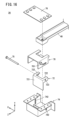
- FIG. 16 is an exploded perspective view of the battery lock mechanism.
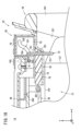
- FIG. 17 is a cross-sectional view of the battery lock mechanism.
- FIG. 18 is a cross-sectional view of the battery lock mechanism.
- FIG. 19 is a cross-sectional view of the battery lock mechanism.
- FIG. 20 is a front view of the slot.
- FIG. 21 is a front view of the slot.
- 22A, 22B and 22C are cross-sectional views of the bottom cover assembly and the mobile battery.
- FIG. 23 is a perspective view of the bottom cover.
- FIG. 24 is a cross-sectional view of the slot.
- FIG. 25 is a cross-sectional view of the slot.
- FIG. 26 is a perspective view of a slot;
- FIG. 27 is a schematic cross-sectional view of the battery exchange.
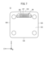
- FIG. 1 is a schematic external view of the battery exchange machine 10.
- the battery exchange 10 is a device that charges the mobile battery 12 .
- the user leaves the mobile battery 12 with a low state of charge (SOC) at the battery exchange 10 .
- the user receives another fully charged mobile battery 12 from the battery exchange 10 .
- the mobile battery 12 has a power storage unit that stores electric power therein.
- the mobile battery 12 corresponds to the electrical equipment and storage device of the present invention.
- the battery exchange 10 has eight slots 14 and one operation panel 16. A user inserts the mobile battery 12 into the slot 14 . When the mobile battery 12 is held in the slot 14 , the battery exchange 10 starts charging the mobile battery 12 .
- the operation panel 16 is a device operated by a user. By operating the operation panel 16, the user pays a fee, for example.
- the slot 14 opens to the front face 101 of the battery exchange machine 10 .
- the front surface 101 of the battery exchange machine 10 is inclined with respect to the vertical direction (the direction of gravity). With the user standing facing the front face 101, the top of the front face 101 is farther away from the user than the bottom of the front face 101 is. This allows the user to lean forward when inserting the mobile battery 12 into the slot 14 . Therefore, it becomes easier to insert the mobile battery 12 into the slot 14 .
- FIG. 2 is a schematic cross-sectional view of the battery changer 10.
- the battery exchange 10 has a power source connector 90 to which an external power source is connected.
- the external power source is, for example, a power system (commercial power source), a battery power source, or the like.
- An inverter 94 is provided on the power transmission path 92 between the power source connector 90 and the slot 14 .
- Inverter 94 functions as an AC/DC converter or a DC/DC converter.
- the battery changer 10 has a controller 18 above the slots 14 .
- the control device 18 functions as a charging control section that controls the inverter 94 and performs charging control and the like in the battery exchange 10 .
- the battery changer 10 has a utility space 20 below the slots 14 .
- a cooling device 96 or the like for cooling the inside of the battery exchange machine 10 may be installed in the utility space 20 .
- the inverter 94 corresponds to the first power converter of the invention.
- the battery exchange machine 10 will be described based on the X-axis, Y-axis, and Z-axis defined as follows.
- the direction in which the mobile battery 12 is inserted into and removed from the slot 14 is defined as the Z-axis direction.
- the direction from the innermost part of the slot 14 toward the opening is defined as +Z-axis direction.
- the +Z-axis direction is the direction in which the mobile battery 12 is pulled out from the slot 14 .
- the direction parallel to the width direction of the battery exchange machine 10 is defined as the X-axis direction.
- the right hand side in the X-axis direction is the +X-axis direction.
- a direction orthogonal to the Z-axis and the X-axis is defined as the Y-axis direction.
- the upper side is the +Y-axis direction.
- the Z-axis direction corresponds to the holding direction of the present invention.
- the Y-axis direction corresponds to the intersecting direction of the present invention.
- a view viewed from the +Z-axis direction may be referred to as a front view.
- FIG. 3 shows a state in which the mobile battery 12 is not inserted into the slot 14.
- FIG. 4 is a cross-sectional view of slot 14 .
- FIG. 4 shows a state in which the mobile battery 12 is inserted into the slot 14.
- the slot 14 has a slot sleeve 22 and a battery locking mechanism 26.
- the slot sleeve 22 holds the mobile battery 12.
- the slot sleeve 22 has a slot body 28 , a slot flange 30 , a slot stay 32 , a slot guide 34 and a bottom cover 36 .
- the slot body 28 is made of aluminum.
- the slot body 28 is not limited to aluminum, and may be made of other metals or resins.
- the durability of the slot body 28 can be increased compared to when the slot body 28 is made of resin.
- the slot body 28 is a cylindrical member. As shown in FIG. 4, the slot body 28 has a holding space 281 inside.
- the holding space 281 is a hole penetrating the slot body 28 in the Z-axis direction. When the mobile battery 12 is held in the slot 14 , most of the mobile battery 12 is held in this holding space 281 .
- the outer shape of the slot body 28 is substantially rectangular.
- the slot body 28 has four sides: a bottom side 282 , a top side 283 , a left side 284 and a right side 285 .
- the slot body 28 has an opening 286 at the +Z-axis direction end and an opening 287 at the ⁇ Z-axis direction end.
- the slot flange 30 is attached to the opening 286 of the slot body 28 on the +Z-axis direction side.
- the slot flange 30 is made of metal.
- the slot flange 30 is not limited to metal, and may be made of resin. When the slot flange 30 is made of metal, the durability of the slot flange 30 can be increased compared to when the slot flange 30 is made of resin.
- a slot stay 32 is attached to the +Z-axis direction side of the slot flange 30 .
- the slot stay 32 is made of resin.
- the slot stay 32 may be made of metal instead of resin.
- the slot stay 32 can be manufactured at a lower cost than when the slot stay 32 is made of metal.
- the slot stay 32 has an insertion opening 321.
- the insertion port 321 is a hole passing through the slot stay 32 in the Z-axis direction. When the slot stay 32 is viewed from the Z-axis direction, the insertion opening 321 is substantially rectangular. The insertion opening 321 is connected to the holding space 281 of the slot body 28 .
- a door 38 is attached to the slot stay 32 as shown in FIGS.
- the door 38 is made of resin.
- the door 38 may be made of metal instead of resin.
- the door 38 can be manufactured at a lower cost than when the door 38 is made of metal.
- the door 38 is rotatably provided around a shaft 381.
- the shaft 381 is attached to the +Y-axis direction side of the slot stay 32 .
- the door 38 is closed when the mobile battery 12 is not inserted into the slot 14. - ⁇ At this time, the door 38 closes the opening 286 on the +Z-axis direction side of the slot body 28 .
- the mobile battery 12 pushes the door 38 in the -Z-axis direction.
- the door 38 rotates around the shaft 381 and opens. At this time, the door 38 opens the opening 286 on the +Z-axis direction side of the slot body 28 .
- the battery lock mechanism 26 is attached to the +Y-axis direction side of the slot stay 32 .
- the battery lock mechanism 26 restricts movement of the mobile battery 12 in the +Z-axis direction. This prevents the user from pulling out the mobile battery 12 from the slot 14 .
- the battery lock mechanism 26 allows the mobile battery 12 to move in the +Z-axis direction. Thereby, the user can pull out the mobile battery 12 from the slot 14 .
- a slot guide 34 is attached to the +Z-axis direction side of the slot stay 32 .
- the slot guide 34 is made of resin.
- the slot guide 34 is not limited to resin, and may be made of metal. When the slot guide 34 is made of resin, the slot guide 34 can be manufactured at a lower cost than when the slot guide 34 is made of metal.
- the slot guide 34 has an insertion opening 341.
- the insertion port 341 is a hole passing through the slot guide 34 in the Z-axis direction. When the slot guide 34 is viewed from the Z-axis direction, the insertion opening 341 is substantially rectangular. The insertion port 341 is connected to the insertion port 321 of the slot stay 32 .
- the bottom cover 36 is attached to the opening 287 of the slot body 28 on the -Z-axis direction side.
- the bottom cover 36 is made of resin.
- the bottom cover 36 may be made of metal instead of resin.
- the bottom cover 36 can be manufactured at a lower cost than when the bottom cover 36 is made of metal.
- a connector unit 40, a fan 42, an electronic circuit board 44, and a holding detection switch 46 are attached to the bottom cover 36.
- the bottom cover assembly 24 is configured with the connector unit 40 , the fan 42 , the electronic circuit board 44 and the holding detection switch 46 attached to the bottom cover 36 .
- the bottom cover assembly 24 will be detailed later.
- the link bar 48 of the battery lock mechanism 26 is provided on the +Y-axis direction side of the slot sleeve 22 .
- Link bar 48 extends from battery lock mechanism 26 toward connector unit 40 .
- the battery locking mechanism 26 including the link bar 48 is longer than the mobile battery 12 retained in the slot sleeve 22 .
- the battery lock mechanism 26 including the link bar 48 extends parallel to the Z-axis direction.
- FIG. 5 is a perspective view of the mobile battery 12.
- FIG. FIG. 6 is a diagram showing the upper surface 121 of the mobile battery 12.
- FIG. 7 is a diagram showing the bottom surface 122 of the mobile battery 12.
- FIG. 8 is a cross-sectional view of the mobile battery 12.
- the longitudinal direction of the mobile battery 12 is the W-axis direction, and the direction from the bottom surface 122 to the top surface 121 is the +W-axis direction.
- the direction in which the side surfaces 123 and 124 of the mobile battery 12 are aligned is the V-axis direction, and the direction from the side surface 123 to the side surface 124 is the +V-axis direction.
- the direction in which the side surfaces 125 and 126 are aligned is defined as the U-axis direction, and the direction from the side surface 125 to the side surface 126 is defined as the +U-axis direction.
- a handle 13 is provided on the upper surface 121 of the mobile battery 12 .
- the handle 13 has a first grip portion 131 and a second grip portion 132 .
- the first grip portion 131 extends in the U-axis direction.
- the second grip portion 132 extends in the V-axis direction. The user grips the handle 13 and inserts/removes the mobile battery 12 into/from the slot 14 .
- the side surface 124 is curved outwardly.
- the side surfaces 123, 124, 125 and 126 are substantially planar.
- a female connector 49 is provided on the bottom surface 122 of the mobile battery 12 as shown in FIGS.
- Female connector 49 is also referred to as a receptacle.
- Female connector 49 is exposed to the outside of mobile battery 12 .
- the female connector 49 is arranged on the +V-axis direction side of the center of the bottom surface 122 in the V-axis direction.
- Female connector 49 is provided in recessed portion 127 of mobile battery 12 .
- the depressed portion 127 is recessed in the +W-axis direction from the bottom surface 122 .
- the female connector 49 is arranged in the +W-axis direction from the bottom surface 122 .
- FIG. 9, 10 and 11 are perspective views of the slot 14.
- FIG. 9, 10 and 11 show the structure of the bottom cover assembly 24 and its surroundings.
- FIG. 10 shows the structure with the bottom cover assembly 24 removed from the slot body 28 .
- 12 is a perspective view of the bottom cover 36.
- the bottom cover assembly 24 has a connector unit 40, a fan 42, an electronic circuit board 44 and a holding detection switch 46.
- the connector unit 40 , fan 42 , holding detection switch 46 and electronic circuit board 44 are attached to the bottom cover 36 .
- the bottom cover 36 and the opening 287 of the slot body 28 are fastened with the bolts 37 .
- the bottom cover assembly 24 is thereby fixed to the slot body 28 .
- the connector unit 40 has a base 50, a connection detection switch 52, a disconnection detection switch 54, a connector holder 56, a male connector 58 and a motor 60.
- Male connector 58 is also referred to as a plug.
- the base 50 is fixed to the -Z-axis side surface of the bottom cover 36 .
- the base 50 extends in the ⁇ Z-axis direction from the surface of the bottom cover 36 on the ⁇ Z-axis direction side. Therefore, many members can be attached to the base 50 .
- the base 50 may be formed integrally with the bottom cover 36 .
- the base 50 has a base body 501 , two base flanges 502 and a switch mounting surface 503 .
- the two base flanges 502 are integrally formed with the base body 501.
- One base flange 502 is provided on the +X-axis direction side of the base body 501 .
- Another base flange 502 is provided on the ⁇ X-axis direction side of the base body 501 .
- Each base flange 502 extends in the X-axis direction from the +Z-axis direction side end of the base body 501 .
- the base flange 502 and the bottom cover 36 are fastened with bolts 504 .
- the base 50 is thereby fixed to the bottom cover 36 .
- the switch mounting surface 503 is formed integrally with the base body 501.
- the switch mounting surface 503 is provided on the +X-axis direction side of the base body 501 .
- the switch mounting surface 503 extends in the -Y-axis direction from the end of the base body 501 on the -X-axis direction side.
- connection detection switch 52 and a disconnection detection switch 54 are attached to the switch mounting surface 503 .
- the connection detection switch 52 and the disconnection detection switch 54 are separated from each other in the Z-axis direction.
- the connection detection switch 52 is arranged in the +Z-axis direction
- the disconnection detection switch 54 is arranged in the -Z-axis direction.
- the connection detection switch 52 corresponds to the first detection section of the invention.
- the disconnection detection switch 54 corresponds to the second detection section of the present invention.
- a connector holder 56 is attached to the +Y-axis direction side surface of the base body 501 .
- the connector holder 56 has two guide holes 561 , a connector mounting portion 562 , a rack 563 and a switch operator 564 .
- each guide hole 561 penetrates the connector holder 56 in the Y-axis direction.
- the guide hole 561 extends in the Z-axis direction.
- the two guide holes 561 are separated from each other in the X-axis direction.
- Two guide pins 565 are inserted into each guide hole 561 .
- the guide pin 565 is fixed to the base body 501 of the base 50 . As a result, the connector holder 56 moves relative to the base 50 in the Z-axis direction.
- a male connector 58 is attached to the connector attachment portion 562 .
- the male connector 58 is thereby held by the connector holder 56 .
- the male connector 58 is arranged in the +Y-axis direction from the holding detection switch 46 . Accordingly, it is possible to prevent the male connector 58 from being exposed to liquid that has entered the slot sleeve 22 .
- Male connector 58 is connected to female connector 49 of mobile battery 12 . As a result, power is supplied from the male connector 58 to the mobile battery 12 and the mobile battery 12 is charged.
- the rack 563 is arranged in the -Z-axis direction from the connector mounting portion 562 .
- Rack 563 extends in the Z-axis direction.
- the +Y axis direction side of the rack 563 is not exposed to the outside.
- the ⁇ Y-axis direction side of the rack 563 is exposed to the outside.
- the switch actuator 564 is attached to the side surface of the connector holder 56 on the -X axis direction side.
- the switch operator 564 moves in the Z-axis direction together with the connector holder 56 .
- the switch actuator 564 extends from the connector holder 56 along the switch mounting surface 503 of the base 50 in the -Y-axis direction.
- a motor 60 is attached to the surface of the base body 501 of the base 50 on the -Y-axis direction side.
- Motor 60 has a drive shaft (not shown).
- a drive shaft extends from the motor 60 in the +Y-axis direction.
- the tip of the drive shaft is inserted into the connector holder 56 .
- a pinion 601 is attached to the tip of the drive shaft of the motor 60 .
- Pinion 601 meshes with rack 563 .
- Motor 60 is thereby mechanically connected to male connector 58 via pinion 601 , rack 563 and base 50 .
- the motor 60, pinion 601 and rack 563 correspond to the driving section of the present invention.
- FIG. 13 and 14 are cross-sectional views of the slot 14.
- FIG. 13 and 14 show the structure of the bottom cover assembly 24 and its periphery.
- FIG. 13 shows a state in which the connector holder 56 has moved in the +Z-axis direction.
- FIG. 14 shows a state in which the connector holder 56 has moved in the -Z-axis direction.
- the motor 60 moves the connector holder 56 in the +Z-axis direction.
- the male connector 58 moves in the +Z-axis direction and enters the slot sleeve 22 through the connector insertion hole 361 of the bottom cover 36 shown in FIG.
- the male connector 58 is connected to the female connector 49 of the mobile battery 12, as shown in FIG.
- the switch operating element 564 contacts the movable contact piece 521 of the connection detection switch 52 and presses the movable contact piece 521 in the +Z-axis direction.
- the connection detection switch 52 is turned on from off.
- the movable contact piece 521 corresponds to the connection detector of the present invention.
- the motor 60 moves the connector holder 56 in the -Z-axis direction.
- the male connector 58 moves in the ⁇ Z-axis direction and retreats from the slot sleeve 22 through the connector insertion hole 361 of the bottom cover 36 .
- the male connector 58 is disconnected from the female connector 49 of the mobile battery 12, as shown in FIG.
- the switch operator 564 contacts the movable contact piece 541 of the disconnection detection switch 54 and presses the movable contact piece 541 in the -Z-axis direction.
- the disconnection detection switch 54 is turned on from off.
- the movable contact piece 541 corresponds to the disconnection detector of the present invention.
- the male connector 58 moves in the Z-axis direction.
- the Z-axis direction is the same as the moving direction of mobile battery 12 when mobile battery 12 is inserted into slot 14 . That is, the moving direction of the male connector 58 and the moving direction of the mobile battery 12 are the same. Therefore, even if the connector unit 40 fails while the male connector 58 is connected to the female connector 49 of the mobile battery 12, the user can remove the mobile battery 12 from the slot 14 and the male connector 58 and the female connector 49 can be disconnected.
- the fan 42 is attached to the -Z axis side of the intake port 362 of the bottom cover 36 shown in FIG.
- the intake port 362 communicates between the inside and outside of the slot sleeve 22 . Air is sent inside the slot sleeve 22 by driving the fan 42 .
- the electronic circuit board 44 is arranged in the -X-axis direction from the fan 42. As shown in FIG. A cable 62 is wired between the electronic circuit board 44 and the fan 42 . A cable 64 is wired between the electronic circuit board 44 and the motor 60 . Electricity is supplied to the fan 42 and the motor 60 from the electronic circuit board 44 . Thereby, the fan 42 and the motor 60 are driven.
- the electronic circuit board 44 is equipped with a control section 66 and a storage section 68 .
- a holding detection switch 46 is mounted on the electronic circuit board 44 .
- An electronic circuit is formed on the electronic circuit board 44 .
- a control section 66, a storage section 68, a holding detection switch 46, and many other electronic devices and electric devices are mounted on the electronic circuit.
- the control unit 66 controls charging of the mobile battery 12 held in the slot 14 .
- the control unit 66 is realized by, for example, a processing circuit.
- the processing circuit is configured by an integrated circuit such as ASIC (Application Specific Integrated Circuit) or FPGA (Field-Programmable Gate Array).
- the processing circuit may be configured by an electronic circuit including a discrete device.
- the processing circuit may be configured by a processor such as a CPU (Central Processing Unit) or a GPU (Graphics Processing Unit). In this case, the processing circuit is realized by executing the program stored in the storage unit 68 by the processor.
- the holding detection switch 46 is attached to the switch hole 363 of the bottom cover 36 shown in FIG. 12 from the -Z axis direction side.
- a plunger 461 of the holding detection switch 46 passes through the switch hole 363 and is exposed inside the bottom cover 36 .
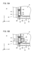
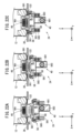
- FIG. 15A and 15B are cross-sectional views of the slot 14.
- FIG. 15A and 15B show the holding detection switch 46 and its surrounding structure.
- 15A and 15B show the structure in which the mobile battery 12 is held in the slot 14.
- FIG. 15A and 15B show the structure in which the mobile battery 12 is held in the slot 14.
- the bottom surface 122 of the mobile battery 12 pushes the plunger 461 of the holding detection switch 46 as shown in FIG. 15A.
- the hold detection switch 46 is switched from off to on.
- the plunger 461 of the holding detection switch 46 is inserted into the recessed portion 127 of the mobile battery 12 as shown in FIG. 15B. be done. Therefore, the bottom surface 122 of the mobile battery 12 cannot press the plunger 461 of the holding detection switch 46 . As a result, the hold detection switch 46 remains off.
- the connector unit 40, the fan 42, the electronic circuit board 44, and the holding detection switch 46 are arranged to fit inside the outer edge of the bottom cover 36 when the bottom cover 36 is viewed from the -Z-axis direction. That is, the connector unit 40 , the fan 42 , the electronic circuit board 44 and the holding detection switch 46 are arranged within the range of parallel projection of the outer edge of the bottom cover 36 .
- the parallel projection of the outer edge of the bottom cover 36 is a virtual area obtained by projecting the outer edge of the bottom cover 36 in the extension direction of the slot sleeve 22 (the insertion/removal direction of the mobile battery 12 or the Z-axis direction).
- the connector unit 40, the fan 42, the electronic circuit board 44, and the holding detection switch 46 can be prevented from interfering with surrounding members.
- FIG. 17, 18 and 19 are sectional views of the battery lock mechanism 26.
- FIG. 17, 18 and 19 show the structure of the battery lock mechanism 26 and its periphery.
- 17 shows the unlocked state of the battery lock mechanism 26.
- FIG. 18 and 19 show the locked state of the battery lock mechanism 26.
- FIG. 20 and 21 are front views of the slot 14.
- FIG. 20 shows the unlocked state of the battery lock mechanism 26.
- FIG. 21 shows the locked state of the battery lock mechanism 26.
- FIG. 20 shows the unlocked state of the battery lock mechanism 26.
- the battery lock mechanism 26 has a link bar 48, a cam 70, a stopper 72, a lock cover 74, a camshaft 75 and a lock top 76.
- the battery lock mechanism 26, the link bar 48 and the cam 70 correspond to the connecting portion of the present invention.
- the -Z-axis direction side of the link bar 48 is fixed to the connector mounting portion 562 of the connector holder 56. As shown in FIGS. As a result, the link bar 48 moves in the Z-axis direction together with the male connector 58 attached to the connector attachment portion 562 . Note that the link bar 48 may be directly fixed to the male connector 58 .
- the link bar 48 corresponds to the translating part of the invention.
- the +Z-axis direction side of the link bar 48 is fixed to the cam 70 .
- the cam 70 moves in the Z-axis direction together with the link bar 48 .
- the cam 70 has a cam slit 701.
- the cam slits 701 are formed on both sides of the cam 70 in the X-axis direction.
- the cam slit 701 penetrates the cam 70 in the X-axis direction.
- the cam slit 701 has a first parallel portion 702, a second parallel portion 703 and an inclined portion 704.
- the first parallel portion 702 and the second parallel portion 703 extend in the Z-axis direction.
- the Z-axis direction is the same as the moving direction of the link bar 48 and cam 70 .
- the Z-axis direction is a direction that intersects the Y-axis direction, which is the moving direction of the stopper 72, which will be described later.
- the inclined portion 704 is arranged between the first parallel portion 702 and the second parallel portion 703 .
- the first parallel portion 702 extends in the +Z-axis direction from the +Z-axis direction side end of the inclined portion 704 .
- a second parallel portion 703 extends in the ⁇ Z-axis direction from the ⁇ Z-axis direction side end of the inclined portion 704 .
- the cam 70 corresponds to the converting portion of the invention.
- the stopper 72 has a stopper main body 721 and two connecting portions 722.
- the stopper main body 721 is plate-shaped.
- Each of the two connecting portions 722 extends in the ⁇ Z-axis direction from the +Y-axis direction end of the stopper body 721 .
- the two connecting portions 722 are separated from each other in the X-axis direction.
- Each connecting portion 722 has a shaft hole 723 .
- the shaft hole 723 penetrates the connecting portion 722 in the X-axis direction.
- the stopper 72 corresponds to the advance/retreat portion of the present invention.
- the lock cover 74 has stopper slits 741 and guide slits 742 .
- the stopper slit 741 is formed on the surface of the lock cover 74 on the -Y axis direction side.
- the stopper slit 741 penetrates the lock cover 74 in the Y-axis direction.
- the stopper slit 741 extends in the X-axis direction.
- the stopper main body 721 is inserted into this stopper slit 741 .
- the guide slits 742 are formed on both sides of the lock cover 74 in the X-axis direction.
- the guide slit 742 penetrates in the X-axis direction.
- the camshaft 75 is inserted into the guide slit 742 of the lock cover 74 , the cam slit 701 of the cam 70 and the shaft hole 723 of the stopper 72 .
- the stopper 72 is positioned in the +Z-axis direction from the upper surface 121 of the mobile battery 12 while the mobile battery 12 is held in the slot 14 .
- the lock top 76 is fixed to the +Y-axis direction side of the lock cover 74 with the cam 70 and the stopper 72 assembled to the lock cover 74 .
- a lock rubber 78 is provided between the lock cover 74 and the slot stay 32 .
- the lock rubber 78 is made of resin.
- the lock rubber 78 has stopper slits 781 .
- the stopper slit 781 penetrates the lock cover 74 in the Y-axis direction.
- the stopper slit 781 extends in the X-axis direction.
- a stopper body 721 of the stopper 72 is inserted into the stopper slit 781 .
- the lock rubber 78 is in close contact with the stopper main body 721 inserted into the stopper slit 781 . This can prevent water or the like from entering the inside of the lock cover 74 from between the stopper main body 721 and the stopper slit 741 of the lock cover 74 .
- the stopper 72 is mechanically connected to the male connector 58 via the battery lock mechanism 26 and the connector holder 56.
- Battery lock mechanism 26 has link bar 48 and cam 70 as described above. Therefore, it can also be said that the stopper 72 is mechanically connected to the male connector 58 by the link bar 48 , the cam 70 and the connector holder 56 .
- the link bar 48 transmits to the cam 70 the Z-axis movement of the connector holder 56 moving together with the male connector 58 .
- the cam 70 converts movement of the link bar 48 in the Z-axis direction into movement of the stopper 72 in the Y-axis direction.
- the stopper 72 is mechanically connected to the drive section (motor 60, pinion 601 and rack 563) by the link bar 48, cam 70 and connector holder 56.
- the common motor 60 can be used as a drive source for moving the male connector 58 in the Z-axis direction and a drive source for moving the stopper 72 in the Y-axis direction. Therefore, since the number of drive sources can be reduced, the manufacturing cost of the slot 14 can be suppressed.
- the term "mechanically connected” does not only refer to a state of being connected by a rigid body such as the link bar 48, but also includes a state of being connected by meshing of a plurality of gears or the like.
- the timing at which the male connector 58 moves and the timing at which the stopper 72 moves may not match.
- the male connector 58 and the stopper 72 are mechanically connected to each other so that the stopper 72 interlocks with the male connector 58 . Therefore, the timing of movement of the male connector 58 and the timing of movement of the stopper 72 can be reliably matched.
- the battery lock mechanism 26 including the link bar 48 is longer than the mobile battery 12 held in the slot sleeve 22. Therefore, the stopper 72 can be arranged in the +Z-axis direction from the mobile battery 12 . As a result, when the mobile battery 12 is pulled out in the +Z-axis direction while the battery lock mechanism 26 is in the locked state, the stopper 72 comes into contact with the upper surface 121 of the mobile battery 12 . Therefore, it is not necessary to provide a groove or the like that engages with the stopper 72 on the side surface 123 , side surface 124 , side surface 125 or side surface 126 of the mobile battery 12 .
- the camshaft 75 is positioned at the second parallel portion 703 of the cam slit 701 of the cam 70 . At this time, even if force in the +Y-axis direction acts on the stopper 72, movement of the stopper 72 in the +Y-axis direction is restricted. As a result, the battery lock mechanism 26 can be prevented from being unlocked.
- the retention detection switch 46 When the retention detection switch 46 switches from ON to OFF, the retention detection switch 46 detects that the mobile battery 12 has been removed from the slot 14 . In this case, as shown in FIG. 14, the motor 60 moves the male connector 58 together with the connector holder 56 in the -Z-axis direction. This separates the male connector 58 from the female connector 49 of the mobile battery 12 . Movement of the connector holder 56 in the ⁇ Z-axis direction is transmitted to the cam 70 of the battery lock mechanism 26 via the link bar 48 . As shown in FIG. 17, movement of the cam 70 in the -Z-axis direction causes the stopper 72 to move in the +Y-axis direction. As a result, the battery lock mechanism 26 is unlocked.
- the holding detection switch 46 When the holding detection switch 46 is off, the holding detection switch 46 does not detect that the mobile battery 12 is held in the slot 14. In this case, motor 60 does not move male connector 58 in the +Z-axis direction. Thereby, the male connector 58 does not approach the female connector 49 of the mobile battery 12 .
- FIG. 9 shows a state where the connector holder 56 is positioned most in the +Z-axis direction.
- the switch operator 564 contacts the movable contact piece 521 of the connection detection switch 52 and presses the movable contact piece 521 in the +Z-axis direction.
- the connection detection switch 52 is turned on.
- the position of the male connector 58 at this time is the connection position.
- the position of each member of the battery lock mechanism 26 including the male connector 58 and the link bar 48 when the male connector 58 is in the connected position corresponds to the first position of the present invention.
- the connection detection switch 52 detects that the male connector 58 is positioned at the connection position and that the male connector 58 and the female connector 49 of the mobile battery 12 are connected.
- FIG. 11 shows the state where the connector holder 56 is positioned most in the -Z-axis direction.
- the switch operator 564 contacts the movable contact piece 541 of the disconnection detection switch 54 and presses the movable contact piece 541 in the -Z-axis direction.
- the disconnection detection switch 54 is turned on.
- the position of the male connector 58 at this time is the disconnection position.
- the disconnection detection switch 54 detects that the male connector 58 is positioned at the disconnection position and the connection between the male connector 58 and the female connector 49 of the mobile battery 12 is disconnected.
- the position of each member of the battery lock mechanism 26 including the male connector 58 and the link bar 48 when the male connector 58 is in the disconnected position corresponds to the second position of the present invention.
- FIG. 22A, 22B and 22C are cross-sectional views of the bottom cover assembly 24 and the mobile battery 12.
- FIG. 22A, 22B and 22C are cross-sectional views of the bottom cover assembly 24 and the mobile battery 12.
- FIG. 22A shows the state when the male connector 58 is positioned at the disconnected position.
- the tip of the terminal 581 of the male connector 58 is positioned in the ⁇ Z-axis direction relative to the bottom cover 36, as shown in FIG. 22A.
- the disconnection detection switch 54 is turned on, and the connection detection switch 52 is turned off.
- FIG. 22B shows a state in which the male connector 58 has moved in the +Z-axis direction from the disconnected position.
- the tip of the terminal 581 passes through the connector insertion hole 361 of the bottom cover 36 .
- the tip of the terminal 581 that has passed through the connector insertion hole 361 is inserted into the terminal hole 491 of the female connector 49 of the mobile battery 12 .
- both the disconnection detection switch 54 and the connection detection switch 52 are turned off.
- FIG. 22C shows the state when the male connector 58 is positioned at the connection position.
- the connection between the male connector 58 and the female connector 49 of the mobile battery 12 is completed.
- the disconnection detection switch 54 is turned off, and the connection detection switch 52 is turned on.
- connection detection switch 52 detects that the male connector 58 and the female connector 49 are connected while the male connector 58 is moving toward the female connector 49 of the mobile battery 12
- the controller 66 controls the motor 60 to stop the male connector 58 .
- the disconnect detection switch 54 detects that the male connector 58 and the female connector 49 are disconnected. In this case, the controller 66 controls the motor 60 to stop the male connector 58 .
- the holding detection switch 46 detects that the mobile battery 12 is held in the slot 14
- the connection detection switch 52 detects that the male connector 58 and the female connector 49 of the mobile battery 12 are connected.
- the control unit 66 permits the use of the mobile battery 12 . Specifically, the control unit 66 controls charging of the mobile battery 12 and charges the mobile battery 12 . At this time, the battery lock mechanism 26 is locked, and the user cannot pull out the mobile battery 12 from the slot 14 .
- the holding detection switch 46 does not detect that the mobile battery 12 is held in the slot 14, or the connection detection switch 52 detects that the male connector 58 and the female connector 49 of the mobile battery 12 are connected. If not, the control unit 66 prohibits the use of the mobile battery 12 . Specifically, the control unit 66 does not perform charging control of the mobile battery 12 and does not charge the mobile battery 12 . At this time, the battery lock mechanism 26 is unlocked, and the user can pull out the mobile battery 12 from the slot 14 .
- the battery exchanger 10 of this embodiment has a mechanism for discharging liquid such as rainwater from the inside of the slot 14 to the outside.
- the configuration of the battery exchanging machine 10 of the present embodiment is the same as that of the battery exchanging machine 10 of the first embodiment except for the construction described below.
- FIG. 23 is a perspective view of the bottom cover 36.
- FIG. 24 is a cross-sectional view of the slot 14.
- FIG. FIG. 24 shows a state in which mobile battery 12 is held in slot 14 .
- the bottom cover 36 has a connector insertion hole 361, an intake port 362, a switch hole 363, and a drainage channel 364.
- the drainage channel 364 drains liquid such as rainwater from the inside of the slot sleeve 22 to the outside.
- the drainage channel 364 is arranged in the ⁇ Y-axis direction from the intake port 362 and the switch hole 363 . That is, the drainage channel 364 is arranged vertically below the intake port 362 and the switch hole 363 . Thereby, as shown in FIG. 24, the drainage path 364 is arranged vertically below the fan 42 and the holding detection switch 46 .
- the drainage channel 364 is composed of a first drainage channel 365 and a second drainage channel 366 .
- the portion of the bottom cover 36 in the -Y-axis direction from the position where the holding detection switch 46 is attached is concave in the -Z-axis direction. This concave portion extends in the X-axis direction as shown in FIG. This concave portion constitutes the first drainage channel 365 .
- An opening opening in the Y-axis direction is formed at the end of the first drainage channel 365 on the -X-axis direction side. This opening constitutes the second drainage channel 366 .
- a filtering member 80 is attached to the first drainage channel 365 .
- the filtering member 80 is fitted into the concave first drainage channel 365 .
- the filtering member 80 is attachable to and detachable from the first drainage channel 365 .
- Two ribs 367 are formed in the +Y-axis direction from the first drainage channel 365 .
- the two ribs 367 press the portion of the filtering member 80 protruding from the first drainage channel 365 in the -Y-axis direction.
- the filtering member 80 may be, for example, a porous member such as a sponge filter.
- FIG. 25 is a cross-sectional view of the slot 14.
- FIG. FIG. 25 is an enlarged view of the drainage channel 364 and its vicinity.
- FIG. 25 shows the mobile battery 12 held in the slot sleeve 22 .
- the liquid that has entered the slot 14 passes through the filtering member 80 of the first drainage channel 365 and is discharged to the outside of the slot 14 through the second drainage channel 366, as indicated by the arrows in FIG.
- the filter member 80 By providing the filter member 80 in the first drain 365 , the liquid flow is dispersed or decelerated while passing through the filter member 80 . As a result, it is possible to prevent the liquid from being discharged from the slot 14 with force.
- Solid dust such as dust, fallen leaves, and paper may enter the inside of the slot sleeve 22 .
- the provision of the filtering member 80 in the first drain 365 allows debris to be retained inside the slot sleeve 22 . Dust accumulated inside the slot sleeve 22 can be removed together with the filtering member 80 .
- the intake port 362 and the drainage channel 364 are formed in the bottom cover 36 , cleaning of the intake port 362 and the drainage channel 364 can be performed with the bottom cover 36 removed from the slot body 28 .
- the shape of the bottom cover 36 is different from that of the battery exchanging machine 10 of the first embodiment.
- the configuration of the battery exchanging machine 10 of the present embodiment is the same as that of the battery exchanging machine 10 of the first embodiment except for the construction described below.
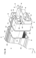
- FIG. 26 is a perspective view of the slot 14.
- FIG. 26 shows the bottom cover assembly 24 removed from the slot body 28.
- FIG. 26 is a perspective view of the slot 14.
- FIG. 26 shows the bottom cover assembly 24 removed from the slot body 28.
- the bottom cover 36 has one bottom surface 371 and four side surfaces 372 , 373 , 374 and 375 .
- the bottom surface 371 is formed in a rectangular shape when viewed from the +Z-axis direction.
- a side surface 372 , a side surface 373 , a side surface 374 , and a side surface 375 extend in the +Z-axis direction from each of the four sides of the bottom surface 371 .
- the battery exchanges 10 of the first to third embodiments described above are exchanges having a charging function. That is, the battery exchange 10 of the first to third embodiments functions as a charging device.
- the battery exchange 10 may be an exchange having a power feeding function. That is, the battery exchange 10 may function as a power supply device.
- the battery exchange machine 10 may be used as a power supply device installed in a house, building, factory, or the like. Also, the battery exchange 10 may be used as a power supply device that supplies electric power to a moving object such as a vehicle, an aircraft, or a ship. Also, the battery exchange 10 may be used as a power supply device that supplies power to a power system (commercial power supply) (reverse power flow).
- a power system commercial power supply
- FIG. 27 is a schematic cross-sectional view of the battery changer 10.
- the battery exchange 10 When the battery exchange 10 is used as a power supply device, the battery exchange 10 has a power supply destination connection unit 100 .
- a power consumption device outside the battery exchange 10 is connected to the power supply destination connection unit 100 .
- a power system (commercial power source) may be connected to the power supply destination connection unit 100 .
- a power consumption device inside the battery exchange 10 may be connected to the power supply destination connection unit 100 .
- the power consumption device inside the battery exchange 10 is, for example, the cooling device 96 and the like.
- An inverter 104 is provided on the power transmission path 102 between the power supply destination connection portion 100 and the slot 14 . Inverter 104 functions as a DC/AC converter or a DC/DC converter.
- the battery changer 10 has a controller 18 above the slots 14 .
- the control device 18 controls the inverter 104 to perform power supply control and the like in the battery exchange 10 .
- Inverter 104 corresponds to
- the slot sleeve 22 entirely covers the mobile battery 12 it holds.
- the slot sleeve 22 may be a member that partially covers the mobile battery 12 that it holds.
- the stopper 72 when the battery lock mechanism 26 is in the locked state, the stopper 72 abuts against the upper surface 121 of the mobile battery 12 to restrict movement of the mobile battery 12 in the +Z-axis direction. do.
- the battery lock mechanism 26 locks the mobile battery 12 in the +Z-axis direction by contacting the contact portions (not shown) provided on the side surfaces 123, 124, 125, and 126 of the mobile battery 12. Movement may be restricted.
- the technology disclosed in Japanese Patent Application Laid-Open No. 10-313543 may be applied to the slots 14 of the first to third embodiments.
- the battery lock mechanism 26 converts the movement of the male connector 58 in the Z-axis direction into the movement of the stopper 72 in the Y-axis direction.
- connection detection switch 52 when the movable contact piece 521 of the connection detection switch 52 is pressed by the switch actuator 564 of the connector holder 56, the connection detection switch 52 moves between the male connector 58 and the mobile terminal. It detects that the female connector 49 of the battery 12 is connected. The connection detection switch 52 detects the connection between the male connector 58 and the female connector 49 of the mobile battery 12 by detecting the position of the switch operating element 564 using an optical method. good too.
- the disconnect detection switch 54 detects the disconnection between the male connector 58 and the female connector 49 of the mobile battery 12 by detecting the position of the switch operating element 564 using an optical method. may be detected.
Landscapes
- Chemical & Material Sciences (AREA)
- Chemical Kinetics & Catalysis (AREA)
- Electrochemistry (AREA)
- General Chemical & Material Sciences (AREA)
- Engineering & Computer Science (AREA)
- Manufacturing & Machinery (AREA)
- Power Engineering (AREA)
- Battery Mounting, Suspending (AREA)
- Details Of Connecting Devices For Male And Female Coupling (AREA)
Abstract
Description
図1は、バッテリ交換機10の外観模式図である。バッテリ交換機10は、モバイルバッテリ12の充電を行う装置である。ユーザは、充電率(SOC: State of Charge)が低くなったモバイルバッテリ12をバッテリ交換機10に預ける。ユーザは、充電が完了した別のモバイルバッテリ12をバッテリ交換機10から受け取る。モバイルバッテリ12は、その内部に、電力を蓄電する蓄電部を有する。モバイルバッテリ12は、本発明の電気機器及び蓄電器に相当する。
図3は、スロット14の斜視図である。図3は、スロット14にモバイルバッテリ12が挿入されていない状態を示す。図4は、スロット14の断面図である。図4は、スロット14にモバイルバッテリ12が挿入されている状態を示す。
図5は、モバイルバッテリ12の斜視図である。図6は、モバイルバッテリ12の上面121を示す図である。図7は、モバイルバッテリ12の底面122を示す図である。図8は、モバイルバッテリ12の断面図である。
図9、図10及び図11は、スロット14の斜視図である。図9、図10及び図11には、ボトムカバーアッシ24とその周辺の構造を示す。図10は、ボトムカバーアッシ24がスロット本体28から取り外された状態の構造を示す。図12は、ボトムカバー36の斜視図である。
図16は、バッテリロック機構26の分解斜視図である。図17、図18及び図19は、バッテリロック機構26の断面図である。図17、図18及び図19は、バッテリロック機構26及びその周辺の構造を示す。図17は、バッテリロック機構26のアンロック状態を示す。図18及び図19は、バッテリロック機構26のロック状態を示す。図20及び図21は、スロット14の正面図である。図20は、バッテリロック機構26のアンロック状態を示す。図21は、バッテリロック機構26のロック状態を示す。
保持検出スイッチ46がオフからオンに切り替わった場合に、保持検出スイッチ46は、モバイルバッテリ12がスロット14に保持されたことを検出する。この場合、図13に示すように、モータ60は、コネクタホルダ56とともに雄型コネクタ58を+Z軸方向に移動させる。これにより、雄型コネクタ58は、モバイルバッテリ12の雌型コネクタ49に接近する。コネクタホルダ56の+Z軸方向の動きは、リンクバー48を介して、バッテリロック機構26のカム70に伝達される。図18に示すように、カム70が+Z軸方向に移動することにより、ストッパ72が-Y軸方向に移動する。これにより、バッテリロック機構26は、ロック状態となる。
本実施形態のバッテリ交換機10は、スロット14の内部から外部に雨水等の液体を排出する機構を有する。本実施形態のバッテリ交換機10について、以下に説明する構成以外の構成は、第1実施形態のバッテリ交換機10と同じである。
本実施形態のバッテリ交換機10では、ボトムカバー36の形状が、第1実施形態のバッテリ交換機10と異なる。本実施形態のバッテリ交換機10について、以下に説明する構成以外の構成は、第1実施形態のバッテリ交換機10と同じである。
12…モバイルバッテリ(電気機器、蓄電器)
14…スロット(保持部)
26…バッテリロック機構(接続部)
48…リンクバー(接続部、並進部)
49…雌型コネクタ(第1電気端子)
52…接続検出スイッチ(第1検出部)
54…接続解除検出スイッチ(第2検出部)
58…雄型コネクタ(第2電気端子)
60…モータ(駆動部)
70…カム(接続部、変換部) 72…ストッパ(進退部)
521…可動接片(接続検出部) 563…ラック(駆動部)
541…可動接片(接続解除検出部)
601…ピニオン(駆動部)
Claims (18)
- 第1電気端子(49)を有する電気機器(12)を保持する保持装置(10)であって、
前記電気機器を保持する保持部(14)と、
前記保持部に保持された前記電気機器の前記第1電気端子に接続される第2電気端子(58)と、
前記第2電気端子を前記第1電気端子に近づく方向に移動させる、及び/又は、前記第2電気端子を前記第1電気端子から離れる方向に移動させる、駆動部(60、563、601)と、
前記電気機器を前記保持部に保持させるときに前記電気機器が移動する軌跡である移動軌跡に対して、進退可能に設けられる進退部(72)と、
前記第2電気端子と前記進退部とを、互いに機械的に接続する接続部(26、48、70)と、
を備える、保持装置。 - 請求項1に記載の保持装置であって、
前記第2電気端子は、前記電気機器を前記保持部に保持させるときに前記電気機器が移動する方向である保持方向に沿って移動するように設けられ、
前記進退部は、前記保持方向と交差する方向である交差方向に進退するように設けられる、保持装置。 - 請求項2に記載の保持装置であって、
前記接続部は、
前記第2電気端子と一体になって移動可能に設けられる並進部(48)と、
前記並進部の前記保持方向の動きを、前記進退部の前記交差方向の動きに変換する変換部(70)と、
を有する、保持装置。 - 請求項1~3のいずれか1項に記載の保持装置であって、
前記電気機器を前記保持部に保持させるときに前記電気機器が移動する方向である保持方向において、
前記第2電気端子は、前記保持部に保持された前記電気機器よりも一方に配置され、
前記進退部は、前記保持部に保持された前記電気機器よりも他方に配置される、保持装置。 - 請求項4に記載の保持装置であって、
前記接続部は、前記保持方向において、前記保持部に保持された前記電気機器よりも長い、保持装置。 - 請求項5に記載の保持装置であって、
前記接続部は、前記保持方向に平行に延びる、保持装置。 - 請求項1~6のいずれか1項に記載の保持装置であって、
前記第2電気端子、前記進退部及び前記接続部は、第1位置と第2位置との間を移動するように設けられ、
前記第1位置は、前記第2電気端子が前記第1電気端子に接続し、前記進退部が前記移動軌跡に進入したときの前記第2電気端子、前記進退部及び前記接続部の位置であり、
前記第2位置は、前記第2電気端子が前記第1電気端子から離間し、前記進退部が前記移動軌跡から退避したときの前記第2電気端子、前記進退部及び前記接続部の位置である、保持装置。 - 請求項7に記載の保持装置であって、
前記第2電気端子、前記進退部及び前記接続部が前記第1位置に位置することを検出する第1検出部(52)を備える、保持装置。 - 請求項8に記載の保持装置であって、
前記第1検出部は、前記第2電気端子の近傍に配置され、
前記第1検出部は、前記第2電気端子が前記第1電気端子に接続したときの位置である接続位置に、前記第2電気端子が位置することを検出する接続検出部(521)を有する、保持装置。 - 請求項9に記載の保持装置であって、
前記駆動部が前記第2電気端子を前記第2位置から前記第1位置に移動させているときに、前記接続検出部が、前記第2電気端子が前記接続位置に位置することを検出した場合に、前記駆動部は前記第2電気端子の移動を停止させる、保持装置。 - 請求項8~10のいずれか1項に記載の保持装置であって、
前記第1検出部が、前記第2電気端子、前記進退部及び前記接続部が前記第1位置に位置することを検出した場合に、前記電気機器の使用を許可する、
又は、前記第1検出部が、前記第2電気端子、前記進退部及び前記接続部が前記第1位置に位置することを検出しない場合に、前記電気機器の使用を禁止する、保持装置。 - 請求項7~11のいずれか1項に記載の保持装置であって、
前記第2電気端子、前記進退部及び前記接続部が前記第2位置に位置することを検出する第2検出部(54)を備える、保持装置。 - 請求項12に記載の保持装置であって、
前記第2検出部は、前記第2電気端子の近傍に配置され、
前記第2検出部は、前記第2電気端子が前記第1電気端子から離間した位置である接続解除位置に、前記第2電気端子が位置することを検出する接続解除検出部(541)を有する、保持装置。 - 請求項13に記載の保持装置であって、
前記駆動部が前記第2電気端子を前記第1位置から前記第2位置に移動させているときに、前記接続解除検出部が、前記第2電気端子が前記接続解除位置に位置することを検出した場合に、前記駆動部は前記第2電気端子の移動を停止させる、保持装置。 - 請求項12~14のいずれか1項に記載の保持装置であって、
前記第2検出部が、前記第2電気端子、前記進退部及び前記接続部が前記第2位置に位置することを検出した場合に、前記保持部から前記電気機器の取り外しを許可する、
又は、前記第2検出部が、前記第2電気端子、前記進退部及び前記接続部が前記第2位置に位置することを検出しない場合に、前記保持部から前記電気機器の取り外しを禁止する、保持装置。 - 請求項1~15のいずれか1項に記載の保持装置であって、
前記電気機器は、その内部に蓄電部を有する蓄電器である、保持装置。 - 請求項1~16のいずれか1項に記載の保持装置であって、
外部の電力源が接続される電力源接続部(90)と、
当該電力源接続部と前記保持部との間における電力伝達経路(92)上に配置される第1電力変換部(94)と、
を備える、保持装置。 - 請求項1~17のいずれか1項に記載の保持装置であって、
外部又は内部の電力供給先が接続される電力供給先接続部(100)と、
当該電力供給先接続部と前記保持部との間における電力伝達経路(102)上に配置される第2電力変換部(104)と、
を備える、保持装置。
Priority Applications (2)
| Application Number | Priority Date | Filing Date | Title |
|---|---|---|---|
| CN202280067691.XA CN118077115A (zh) | 2021-10-07 | 2022-10-07 | 保持装置 |
| JP2023552963A JP7738081B2 (ja) | 2021-10-07 | 2022-10-07 | 保持装置 |
Applications Claiming Priority (2)
| Application Number | Priority Date | Filing Date | Title |
|---|---|---|---|
| JP2021-165805 | 2021-10-07 | ||
| JP2021165805 | 2021-10-07 |
Publications (1)
| Publication Number | Publication Date |
|---|---|
| WO2023058752A1 true WO2023058752A1 (ja) | 2023-04-13 |
Family
ID=85804363
Family Applications (1)
| Application Number | Title | Priority Date | Filing Date |
|---|---|---|---|
| PCT/JP2022/037632 Ceased WO2023058752A1 (ja) | 2021-10-07 | 2022-10-07 | 保持装置 |
Country Status (3)
| Country | Link |
|---|---|
| JP (1) | JP7738081B2 (ja) |
| CN (1) | CN118077115A (ja) |
| WO (1) | WO2023058752A1 (ja) |
Citations (2)
| Publication number | Priority date | Publication date | Assignee | Title |
|---|---|---|---|---|
| JP2004022490A (ja) * | 2002-06-20 | 2004-01-22 | Seiko Instruments Inc | 電池の保持構造、およびそれを用いた電子機器 |
| JP2018163757A (ja) * | 2017-03-24 | 2018-10-18 | 本田技研工業株式会社 | 収容装置 |
-
2022
- 2022-10-07 CN CN202280067691.XA patent/CN118077115A/zh active Pending
- 2022-10-07 WO PCT/JP2022/037632 patent/WO2023058752A1/ja not_active Ceased
- 2022-10-07 JP JP2023552963A patent/JP7738081B2/ja active Active
Patent Citations (2)
| Publication number | Priority date | Publication date | Assignee | Title |
|---|---|---|---|---|
| JP2004022490A (ja) * | 2002-06-20 | 2004-01-22 | Seiko Instruments Inc | 電池の保持構造、およびそれを用いた電子機器 |
| JP2018163757A (ja) * | 2017-03-24 | 2018-10-18 | 本田技研工業株式会社 | 収容装置 |
Also Published As
| Publication number | Publication date |
|---|---|
| CN118077115A (zh) | 2024-05-24 |
| JPWO2023058752A1 (ja) | 2023-04-13 |
| JP7738081B2 (ja) | 2025-09-11 |
Similar Documents
| Publication | Publication Date | Title |
|---|---|---|
| WO2022075426A1 (ja) | 保持装置、保持装置の制御方法、プログラム、及び、非一時的なコンピュータ可読記憶媒体 | |
| CN100479253C (zh) | 电池组 | |
| US5971801A (en) | Service plug having a lever mechanism for positioning circuit terminals and short-circuiting terminals | |
| JP7083355B2 (ja) | 車両インレット用ポートロックアクチュエータ装置 | |
| CN112407068B (zh) | 一种新能源车的充电口系统 | |
| WO2023058752A1 (ja) | 保持装置 | |
| JP2003061229A (ja) | 床用配線器具 | |
| US5497245A (en) | Facsimile machine including a power source adaptor used therein | |
| US7448887B2 (en) | Lever-fitting type connector | |
| WO2022106693A1 (en) | Hvil plug assembly, hvil connection device and method for removing hvil plug assembly | |
| JP2004335114A (ja) | コネクタの接続構造 | |
| CN211063358U (zh) | 巡检机器人、充电装置及巡检机器人充电系统 | |
| CN217768175U (zh) | 一种按钮调速开关 | |
| CN1305249A (zh) | 电连接器安装装置 | |
| WO2023185747A1 (zh) | 插座装置 | |
| CN223305499U (zh) | 一种泳池清洁机器人 | |
| CN102255181B (zh) | 插座及具备该插座的充电装置 | |
| CN224191900U (zh) | 接线盒接头、接线盒及光伏组件 | |
| CN113823951A (zh) | 便携式移动电源 | |
| CN220156255U (zh) | 滑盖机构及储能设备 | |
| JPH08138641A (ja) | 着脱式電源システム | |
| CN223693403U (zh) | 一种直流充电枪 | |
| CN223680489U (zh) | 插头连接器、电子设备和电连接器组件 | |
| CN112205914A (zh) | 鼓风机配件及电动吸尘器 | |
| CN222149917U (zh) | 清洁系统 |
Legal Events
| Date | Code | Title | Description |
|---|---|---|---|
| 121 | Ep: the epo has been informed by wipo that ep was designated in this application |
Ref document number: 22878619 Country of ref document: EP Kind code of ref document: A1 |
|
| WWE | Wipo information: entry into national phase |
Ref document number: 2023552963 Country of ref document: JP |
|
| WWE | Wipo information: entry into national phase |
Ref document number: 2401002198 Country of ref document: TH |
|
| WWE | Wipo information: entry into national phase |
Ref document number: 202280067691.X Country of ref document: CN |
|
| WWE | Wipo information: entry into national phase |
Ref document number: 202417035198 Country of ref document: IN |
|
| NENP | Non-entry into the national phase |
Ref country code: DE |
|
| 122 | Ep: pct application non-entry in european phase |
Ref document number: 22878619 Country of ref document: EP Kind code of ref document: A1 |