WO2023058634A1 - Photoelectric composite connector - Google Patents
Photoelectric composite connector Download PDFInfo
- Publication number
- WO2023058634A1 WO2023058634A1 PCT/JP2022/037079 JP2022037079W WO2023058634A1 WO 2023058634 A1 WO2023058634 A1 WO 2023058634A1 JP 2022037079 W JP2022037079 W JP 2022037079W WO 2023058634 A1 WO2023058634 A1 WO 2023058634A1
- Authority
- WO
- WIPO (PCT)
- Prior art keywords
- optical
- sub
- housing
- connector
- ferrule
- Prior art date
Links
- 239000002131 composite material Substances 0.000 title claims abstract description 64
- 230000003287 optical effect Effects 0.000 claims abstract description 268
- 239000013307 optical fiber Substances 0.000 claims abstract description 14
- 230000013011 mating Effects 0.000 claims description 17
- 230000002093 peripheral effect Effects 0.000 claims description 3
- 238000004891 communication Methods 0.000 description 21
- 238000004519 manufacturing process Methods 0.000 description 18
- 238000000034 method Methods 0.000 description 10
- 230000004308 accommodation Effects 0.000 description 8
- 210000000078 claw Anatomy 0.000 description 7
- 238000005452 bending Methods 0.000 description 6
- 230000000694 effects Effects 0.000 description 5
- 239000013308 plastic optical fiber Substances 0.000 description 5
- 238000004088 simulation Methods 0.000 description 4
- 239000011521 glass Substances 0.000 description 3
- 238000003780 insertion Methods 0.000 description 3
- 230000037431 insertion Effects 0.000 description 3
- 238000005192 partition Methods 0.000 description 3
- 238000002788 crimping Methods 0.000 description 2
- 230000000994 depressogenic effect Effects 0.000 description 2
- 238000009826 distribution Methods 0.000 description 2
- 239000011347 resin Substances 0.000 description 2
- 229920005989 resin Polymers 0.000 description 2
- 240000006829 Ficus sundaica Species 0.000 description 1
- 238000005253 cladding Methods 0.000 description 1
- 230000006835 compression Effects 0.000 description 1
- 238000007906 compression Methods 0.000 description 1
- 239000004020 conductor Substances 0.000 description 1
- 230000008878 coupling Effects 0.000 description 1
- 238000010168 coupling process Methods 0.000 description 1
- 238000005859 coupling reaction Methods 0.000 description 1
- 238000010586 diagram Methods 0.000 description 1
- 230000002708 enhancing effect Effects 0.000 description 1
- 238000005304 joining Methods 0.000 description 1
- 239000002184 metal Substances 0.000 description 1
- 238000012986 modification Methods 0.000 description 1
- 230000004048 modification Effects 0.000 description 1
- 238000003825 pressing Methods 0.000 description 1
- 230000002250 progressing effect Effects 0.000 description 1
- 230000003014 reinforcing effect Effects 0.000 description 1
- 230000000717 retained effect Effects 0.000 description 1
- 239000000758 substrate Substances 0.000 description 1
- 230000001629 suppression Effects 0.000 description 1
Images


Classifications
-
- G—PHYSICS
- G02—OPTICS
- G02B—OPTICAL ELEMENTS, SYSTEMS OR APPARATUS
- G02B6/00—Light guides; Structural details of arrangements comprising light guides and other optical elements, e.g. couplings
- G02B6/24—Coupling light guides
- G02B6/36—Mechanical coupling means
-
- H—ELECTRICITY
- H01—ELECTRIC ELEMENTS
- H01R—ELECTRICALLY-CONDUCTIVE CONNECTIONS; STRUCTURAL ASSOCIATIONS OF A PLURALITY OF MUTUALLY-INSULATED ELECTRICAL CONNECTING ELEMENTS; COUPLING DEVICES; CURRENT COLLECTORS
- H01R13/00—Details of coupling devices of the kinds covered by groups H01R12/70 or H01R24/00 - H01R33/00
- H01R13/46—Bases; Cases
- H01R13/514—Bases; Cases composed as a modular blocks or assembly, i.e. composed of co-operating parts provided with contact members or holding contact members between them
Definitions
- the present disclosure relates to an optical-electrical composite connector.
- Optical cables that use optical fibers are widely used for information communication for household and industrial purposes, as they are capable of high-speed communication of a large amount of information.
- automobiles are equipped with various electronic devices such as a car navigation system, and optical communication using optical cables has begun to be used for communication in these devices.
- speed of communication has been accelerating.
- the importance of optical cables capable of high-speed communication is increasing more and more.
- an optical cable with glass optical fibers can be suitably used for high-speed communication.
- optical cables are not suitable for supplying the energy necessary to operate communication devices, and electric wires with metal wires are also used together with optical cables. Therefore, in order to easily connect the optical cable and the electric wire to a device such as a communication device, a connector has been developed that can collectively connect the optical cable and the electric wire to the device.
- a connector is disclosed in Patent Document 1, etc., and has been put into practical use in part.
- optical-electrical composite connectors have been developed as means for collectively connecting optical cables and electric wires to equipment such as communication equipment. , which tends to be more difficult to manufacture than electrical connectors that connect only wires.
- optical connectors and electrical connectors have completely different manufacturing processes and manufacturing facilities, and it is difficult to manufacture a composite connector that integrates the optical cable connection part and the electric wire connection part on the same production line. That is one reason.
- the objective is to provide an optical-electrical composite connector that is easy to assemble.
- the optical-electrical composite connector of the present disclosure includes at least one optical ferrule to which an optical fiber of an optical cable is coupled, at least one electrical connection terminal to which an electric wire is coupled, and a sub-unit housing the at least one optical ferrule.
- the sub-housing accommodates the optical ferrule and the spring member to constitute an optical sub-connector
- the main housing accommodates and fixes the optical sub-connector and the electrical connection terminals.
- the optical-electrical composite connector according to the present disclosure is an optical-electrical composite connector that is easy to assemble.
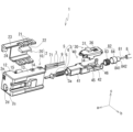
- FIG. 1A and 1B are perspective views showing the entire optical-electrical composite connector according to one embodiment of the present disclosure.
- FIG. 1A shows the state viewed from the front
- FIG. 1B shows the state viewed from the rear.
- FIG. 2 is an exploded perspective view showing the optical-electrical composite connector.
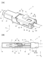
- 3A and 3B are diagrams showing optical sub-connectors included in the optical-electrical composite connector.
- 3A is a perspective view
- FIG. 3B is a partial cross-sectional view showing the AA cross section in FIG. 3A.
- 4A and 4B are side views showing simulation results for estimating the amount of deformation of the sub-housing in the optical sub-connector.
- FIG. 4A shows a form having the engagement structure with the rib shown in FIG. 3A
- FIG. 4B shows a form without the engagement structure with the rib.
- An optical-electrical composite connector contains at least one optical ferrule to which an optical fiber of an optical cable is coupled, at least one electrical connection terminal to which an electric wire is coupled, and the at least one optical ferrule.
- the sub-housing accommodates the optical ferrule and the spring member to constitute an optical sub-connector, and the main housing accommodates and fixes the optical sub-connector and the electrical connection terminals.
- the optical ferrule is not directly housed in the main housing housing the electrical connection terminals, but the optical ferrule is housed in a sub-housing separate from the electrical connection terminals to form an optical sub-connector.
- the optical sub-connector is accommodated in the main housing.
- the optical sub-connector can be manufactured using conventional optical connector manufacturing processes and manufacturing equipment. Compared with the process of directly assembling to the housing, it can be implemented simply.
- the optical sub-connector by providing a spring member inside the sub-housing for urging the optical ferrule toward the distal end side, the optical ferrule within the sub-housing is pressed toward the distal end side.
- the effect of improving manufacturability due to the presence of the spring member is particularly remarkable when using an optical ferrule having a small tip surface area, such as AGF, which is coupled to a thin optical fiber.
- the spring member causes the tip surface of the optical ferrule constituting the optical sub-connector to move the tip surface of the optical ferrule of the mating connector. It is preferable that it presses toward the tip surface of the ferrule. Then, the urging force of the spring member brings the optical ferrules into contact with each other at their distal end surfaces, and further facilitates maintaining the contact state. As a result, the reflection loss of the optical signal between the optical ferrules is suppressed, and good optical connection is obtained. This effect is particularly remarkable when using an optical ferrule with a small tip surface area, such as AGF, which is coupled to a thin optical fiber.
- the sub-housing is composed of two divided members, an upper member and a lower member, which are divided in the vertical direction perpendicular to the longitudinal direction along the axis of the optical ferrule to be accommodated.
- a cable holding part for holding and fixing a cable fixing member attached to the optical cable coupled to the optical ferrule between the two split members;
- the coupled optical ferrule may be housed in the sub-housing while being biased forward by the spring member and with the cable fixing member sandwiched between the cable holding portions. Then, since the sub-housing is composed of two divided members, the process of arranging the optical ferrule and the spring member in the sub-housing to fabricate the optical sub-connector can be easily carried out.
- the optical ferrule is kept biased forward by the spring member, and the cable fixing member attached to the optical cable is sandwiched and held between the two split members, thereby holding the optical ferrule. It can be held in place in the sub-housing, and even when the optical cable is subjected to tension, its optical ferrule arrangement can be kept stable. Therefore, the workability of manufacturing the optical sub-connector and assembling it to the main housing, and the convenience of using the manufactured optical-electrical composite connector are improved.
- two edges ie, the lower edge of the upper member along the front-rear direction and the upper edge of the lower member along the front-rear direction, are butted against each other, and the The upper member and the lower member are joined together, and one of the two edges has a rib projecting toward the other edge in the middle in the front-rear direction.
- a rib accommodating portion as a concave portion that accommodates the rib portion and engages with the rib portion in the middle portion in the front-rear direction.
- the engaging portion that engages the rib portion and the rib accommodating portion in a state in which the upper member and the lower member are coupled to each other is It is preferable that it does not protrude outward from the central axis extending in the front-rear direction. Then, even if the rib portion is provided, the size of the optical sub-connector can be suppressed, and the size of the optical-electrical composite connector as a whole can be suppressed. In addition, when the optical sub-connector is assembled to the main housing, the rib portion does not interfere with the assembly work, so that the assembly workability is improved.
- the outer peripheral surface of the sub-housing has an engaging portion that engages the rib portion and the rib accommodating portion, and locations before and after the engaging portion. So, it is good to be flush with each other. As a result, the effect of suppressing the size of the optical sub-connector and improving the workability in assembly is particularly high.
- the sub-housing is composed of two divided members, a front member and a rear member, which are divided in the front-rear direction along the axis of the optical ferrule to be accommodated, and the rear member has a rear end portion attached to the optical ferrule.
- the optical sub-connector has a cable holding portion for fixing and holding a cable fixing member attached to the optical cable coupled to the ferrule, wherein the optical ferrule coupled to the optical cable is moved forward by the spring member. It is preferable that the cable fixing member is housed in the sub-housing while being biased toward and the cable fixing member being fixed to the cable holding portion.
- the sub-housing is composed of two divided members, so that the process of manufacturing the optical sub-connector can be easily carried out.
- the optical ferrule can be held at a regular position in the sub-housing by the forward biasing of the optical ferrule by the spring member and the fixing of the cable fixing member by the cable holding portion, and the optical cable is not subjected to tension. Even if there is, the arrangement of the optical ferrule can be kept stable. Therefore, the workability of manufacturing the optical sub-connector and assembling it to the main housing, and the convenience of using the manufactured optical-electrical composite connector are improved.
- ⁇ Overview of structure of opto-electric composite connector> 1A, 1B, and 2 show a perspective view and an exploded perspective view, respectively, of an optical-electrical composite connector (hereinafter sometimes simply referred to as a composite connector) 1 according to one embodiment of the present disclosure.
- the composite connector 1 according to this embodiment is connected to the tip of an assembly of an optical cable 8 and an electric wire 9, and performs optical connection for optical communication and electrical connection for conduction at the same time.
- the composite connector 1 according to this embodiment is not fixed to a member such as a communication device or a printed circuit board, but is configured as a cable connector that can be attached to and detached from a mating connector together with an optical cable 8 and electric wires 9. there is
- the composite connector 1 includes at least one optical ferrule 5 as an optical communication portion and at least one electrical connection terminal 7 as an electrical connection portion.
- a sub-housing 3 is provided as a housing member for housing the optical ferrule 5 .
- the sub-housing 3 accommodates the spring member 6 together with the optical ferrule 5 to constitute the optical sub-connector S.
- the composite connector 1 includes a main housing 2 capable of collectively housing the sub-housing 3 and the electrical connection terminals 7.
- the main housing 2 houses and fixes the optical sub-connector S and the electrical connection terminals 7. ing.
- the direction in which the optical-electrical composite connector 1 is connected to the mating connector is defined as the front
- the direction in which the optical cable 8 and the electric wire 9 are connected is defined as the rear. That is, the axial direction of the optical ferrule 5 and the electrical connection terminal 7 is the front-rear direction, and the distal end side of the optical ferrule 5 and the electrical connection terminal 7 is the front.
- the direction perpendicular to the front-rear direction and in which the pair of electrical connection terminals 7 and the sub-housing 3 accommodating the optical ferrule 5 are arranged side by side is defined as the vertical direction (direction c), and the direction perpendicular to the front-rear direction and the vertical direction. is the width direction (b direction).
- the optical ferrule 5 is composed of a known ferrule for optical fibers, and the optical cable 8 is fixed.
- the types of the optical cable 8 and the optical ferrule 5 are not particularly limited, but from the viewpoint of application to high-speed communication, the optical cable 8 may be provided with a glass optical fiber (AGF). is preferred.
- AGF glass optical fiber
- the widely used AGF has a cladding diameter of 125 ⁇ m, and even the multimode type often has a small core diameter of 100 ⁇ m or less.
- the optical cable 8 is coupled and fixed to the optical ferrule 5 so that the optical fiber 81 exposed at the tip is flush with the tip surface of the optical ferrule 5 .
- a cable fixing member 82 consisting of a stop ring 83 and a crimping ring 84 is provided by fixing to the outer circumference of the optical cable 8.
- the stop ring 83 is an annular member.
- the caulking ring 84 is a stepped cylindrical member having a large diameter portion 841 at the front and a small diameter portion 842 having a smaller diameter than the large diameter portion 841 continuously from the large diameter portion 841 at the rear. have.
- a reinforcing wire (not shown) pulled out from the optical cable 8 is sandwiched between the stop ring 83 and the large-diameter portion 841 of the caulking ring 84 disposed on the outer periphery thereof, and the caulking ring 84 is attached to the optical cable at the small-diameter portion 842. It is fixed on the outer cover of 8.
- the number of optical ferrules 5 included in the composite connector 1 is one in the illustrated embodiment, it may be plural.
- each optical ferrule 5 is independently coupled to the optical fiber 81 .
- the plurality of optical ferrules 5 may be housed in a common sub-housing 3 together with the corresponding spring members 6 to form an optical sub-connector S.
- the main housing 2 may house a plurality of optical sub-connectors S configured by housing one or more sets of optical ferrules 5 and spring members 6 in the sub-housing 3 .
- the electrical connection terminal 7 is configured as a known electrical connection terminal for insulated wires.
- the electrical connection terminal 7 is fixed to the tip of the insulated wire 9 and electrically connected to the wire conductor exposed at the tip of the insulated wire 9 .
- the type of the electrical connection terminal 7 is not particularly limited, but a fitting type female terminal can be preferably applied.
- the number of electrical connection terminals 7 included in the composite connector 1 is one pair (two), but the number is not particularly limited as long as at least one electrical connection terminal 7 is included.
- the optical ferrule 5 coupled with the optical cable 8 is housed in the sub-housing 3 together with the spring member 6 to form an optical sub-connector S.
- the structures of the sub-housing 3 and the optical sub-connector S will be described in detail later, but in the illustrated form, one optical ferrule 5 is arranged on the central axis of the sub-housing 3 .
- a connection sub-opening 3a is formed in front of the sub-housing 3 so as to face the tip surface of the optical ferrule 5 and serve as an opening into which the optical connection portion of the mating connector including the optical ferrule can enter.
- the main housing 2 has a front end surface 2c on the front side and is configured as a resin member in the shape of a substantially rectangular tube with the rear side open.
- the main housing 2 is formed in a rectangular tubular shape by combining two members, a housing body portion 10 and a retainer member 20 .
- the housing main body 10 has a tubular portion 12 at the front, and an open portion 13 formed integrally with the tubular portion 12 at the rear of the tubular portion 12 and having one width direction (-b direction) open. have.
- the retainer member 20 has a shape that covers the open portion 13 of the housing main body 10 from the outside in the width direction (-b direction).
- a rectangular tubular main housing 2 is formed.
- the retainer member 20 is provided with loop-shaped locking tabs 21 on the upper and lower wall surfaces.
- the housing main body 10 is provided with locking projections 14 capable of locking the locking tabs 21 at positions corresponding to the locking tabs 21 when the retainer member 20 is coupled.
- the main housing 2 may be supplementarily provided with a member for holding the connection between the housing body 10 and the retainer member 20 in addition to the set of the locking tab 21 and the locking projection 14 .
- a claw 15 is provided on the outer wall surface of the housing body 10 ahead of the locking tab 21 and the locking projection 14, and a claw (not shown) that engages with the claw 15 is provided at a corresponding position on the retainer member 20. ) may be provided.
- the sub-connector accommodating space 2f accommodates the sub-housing 3 which accommodates the optical ferrule 5 and the like to form an optical sub-connector S
- the terminal accommodating space 2g accommodates the electrical connection terminals 7 to which the wires 9 are connected.
- the electrical connection terminals 7 and the optical ferrule 5 housed in the sub-housing 3 are arranged in the main housing 2 with their respective axial directions facing the front-rear direction.
- An optical connection opening 2d is formed in the front end face 2c of the main housing 2 at a position in front of the connection sub-opening 3a of the sub-housing 3, and the optical connection portion of the mating connector including the optical ferrule is connected to the optical connection opening. It is possible to enter the interior of the sub-housing 3 through 2d and the sub-opening 3a for connection.
- An electrical connection opening 2e is formed in the front end face 2c at a position in front of each electrical connection terminal 7, so that the electrical connection portion of the mating connector including the electrical connection terminal can enter the terminal accommodating space 2g.
- the opening 2b at the rear end of the sub-connector housing space 2f has a size and shape that can accommodate the sub-housing 3 without rattling.
- the retainer member 20 is provided with a locking inner projection 22 that protrudes inward (+b direction) from the side (-b direction) inner wall surface and serves also as a part of the partition wall 2a.
- the locking inner projection 22 is mutually locked in the front-rear direction with the locking protrusion 31 provided on the outer wall surface of the sub-housing 3 accommodated in the sub-connector accommodating space 2f.
- the sub-housing 3 has a stepped structure 3c at the front end thereof, which has a small cross-sectional area at the front and a large cross-sectional area at the rear (see FIG. 3A). It is retained in the optical connection opening 2d.
- the optical sub-connector S housed in the sub-connector housing space 2f is positioned and fixed at a predetermined position within the main housing 2. As shown in FIG.
- the electrical connection terminals 7 are housed in the terminal housing space 2g.
- a retainer member 20 constituting the main housing 2 is provided with a terminal locking piece 24 at the tip of an extending portion 23 extending forward to a position corresponding to the middle portion of the tubular portion 12 of the housing main body portion 10 . ing.
- This terminal locking piece 24 can be locked to a stepped structure 71 formed on the outer surface of the electrical connection terminal 7 housed in the terminal housing space 2g.
- the locking structure between the terminal locking piece 24 of the retainer member 20 and the stepped structure 71 of the electrical connection terminal 7 positions the electrical connection terminal 7 accommodated in the terminal accommodation space 2g, and allows the electrical connection terminal 7 to be positioned within the main housing 2 at a predetermined position. fixed in position.
- the optical ferrule 5 to which the optical cable 8 is coupled and the spring member 6 are accommodated in the sub-housing 3, and the optical sub-connector S is assembled in advance. Then, the optical sub-connector S and the electrical connection terminal 7 to which the electric wire 9 is coupled are assembled to the main housing 2 .
- the optical sub-connector S and the electrical connection terminals 7 are arranged in the housing body 10 corresponding to the sub-connector housing space 2f and the terminal housing space 2g, respectively.
- a retainer member 20 is coupled to 10 . At this time, the locking inner protrusions 22 and the terminal locking pieces 24 of the retainer member 20 may be locked to the locking projections 31 of the sub-housing 3 and the step structures 71 of the electrical connection terminals 7, respectively.
- the optical ferrule 5 is not directly fixed to the main housing 2, but the optical ferrule 5 is accommodated in the sub housing 3 to form the optical sub connector S. , the optical sub-connector S is assembled and fixed to the main housing 2 together with the electrical connection terminals 7 . This facilitates assembly of the optical communication portion of the composite connector 1 .
- optical connectors and electrical connectors are largely different in manufacturing process and manufacturing equipment, and it is difficult to manufacture connectors including both optical ferrules and electrical connection terminals on the same manufacturing line.
- the optical sub connector S can be assembled independently of the electrical connections by applying conventional manufacturing processes and equipment for optical connectors.
- the process of assembling the thus assembled optical sub-connector S together with the electrical connection terminals 7 into the main housing 2 can be carried out without great difficulty by applying the conventional electrical connector manufacturing process and manufacturing equipment.
- the optical ferrule 5 has a small diameter for AGF, it is likely to be difficult to handle in the connector assembly process. Difficulties caused by the small diameter of the optical ferrule 5 are less likely to occur.
- FIGS. 3A and 3B are perspective views
- FIG. 3B is a cross-sectional view showing the AA cross section in FIG. 3A.
- the sub-housing 3 which is the outer shell of the optical sub-connector S, is configured as a hollow cylindrical resin member having front and rear openings, and can accommodate at least one optical ferrule 5 to which an optical cable 8 is connected. can.
- the sub-housing 3 is composed of two divided members, an upper member 30 and a lower member 40, of which the lower member 40 is the main member.
- the lower member 40 has a tubular portion 41 on the front side, and an open portion 42 on the rear side of the tubular portion 41 integrally with the tubular portion 41 and having an open top.
- the upper member 30 has a shape that covers the open portion 42 of the lower member 40 from above.
- the lower member 40 has a rear engaging piece 43 protruding upward at the rear end portion of the upper edge 44 of the smooth open portion 42 along the front-rear direction.
- a lock claw 431 is formed integrally with the upper end portion of the rear engaging piece 43 .
- the upper member 30 has a rear engagement concave portion 32 at the rear end portion of the smooth lower edge 33 along the front-rear direction.
- the rear engaging recess 32 is formed as a depression that accommodates the rear engaging piece 43 and can lock the lock claw 431 .
- the upper member 30 and the lower member 40 are coupled with the lower edge 33 of the upper member 30 and the upper edge 44 of the lower member 40 facing each other, and the rear engaging piece 43 is accommodated in the rear engaging recess 32 to engage.
- a cylindrical sub-housing 3 is formed by combining them.
- the engagement between the rear engaging piece 43 and the rear engaging concave portion 32 maintains the state in which the upper member 30 and the lower member 40 are connected. Once the engagement structure between the rear engagement piece 43 and the rear engagement recess 32 is engaged, it cannot be easily released.
- the upper member 30 integrally has a rib portion 34 protruding downward at the middle portion of the lower edge 33 in the front-rear direction.
- the lower member 40 has a rib accommodating portion 45 in the front-rear direction middle portion of the upper edge 44 of the lower member 40 .
- the rib housing portion 45 is formed as a recess for housing the rib portion 34 projecting from the upper member 30 and can be engaged with the rib portion 34 .
- the engagement between the rib portion 34 and the rib accommodation portion 45 assists the engagement between the rear engagement piece 43 and the rear engagement recess 32 to maintain the state in which the upper member 30 and the lower member 40 are connected. At the same time, deformation of the sub-housing 3 is suppressed as will be described later.
- the rib portions 34 are formed to occupy a larger area in the front-rear direction than the rear engaging pieces 43 .
- the rib portion 34 is not provided with a claw-like structure for locking, and the rib portion 34 projecting from the lower end edge 33 of the upper member 30 as a plate-like tab has a smooth surface.
- the rib portion 34 and the rib accommodation portion 45 are engaged with each other while the edge is in contact with the smooth edge of the rib accommodation portion 45 formed as a concave structure facing the upper edge 44 of the lower member 40 .
- a cable holding portion 3b for holding the cable fixing member 82 is formed at the rear end portion of the sub-housing 3.
- a depressed portion 35 is formed in the rear end portion of the upper member 30 as a semi-cylindrical depression capable of accommodating the small diameter portion 842 of the cable fixing member 82 (caulking ring 84).
- a window portion 36 is provided forwardly of the recessed portion 35 as an opening into which a portion of the upper side of the large diameter portion 841 of the cable fixing member 82 (caulking ring 84) can be fitted.
- a window 46 into which a portion of the lower side of the large diameter portion 841 of the cable fixing member 82 can be fitted is formed at the rear end of the lower member 40.
- the recessed portion 35 and the two windows 36 and 46 form the cable holding portion 3b, and the cable fixing member 82 holds the optical cable 8.
- the cable fixing member 82 attached to the optical cable 8 is placed on the rear end portion of the lower member 40, the depressed portion 35 provided in the upper member 30 is aligned with the small diameter portion 842 of the fixing member 82, and the window portion
- the optical ferrule 5 is coupled and the cable fixing member 82 is attached.
- the optical cable 8 is firmly held in the sub-housing 3 by the cable fixing member 82 .
- a ferrule holding portion 47 is provided inside the cylindrical portion 41 of the lower member 40 as a tapered space along the tapered shape of the flange portion 52 in the middle of the optical ferrule 5. , the ferrule holding portion 47 positions the optical ferrule 5 within the sub-housing 3 .
- a spring member 6 made of a coil spring is arranged behind the optical ferrule 5 .
- a part of the spring member 6 on the front side is accommodated in the tubular portion 41 with the expansion axis directed in the front-rear direction.
- a spring insertion portion 51 at the rear end of the optical ferrule 5 is inserted into the hollow portion of the spring member 6 from the front.
- the rear end of the spring member 6 is positioned by abutting on a spring holding projection 37 projecting downward from the inside of the upper member 30 .
- the distance between the rear end surface of the flange portion 52 of the optical ferrule 5 positioned by the ferrule holding portion 47 and the spring holding protrusion 37 is set shorter than the natural length of the spring member 6,
- the spring member 6 is held between the flange 52 of the optical ferrule 5 and the spring holding projection 37 in a compressed state.
- the spring member 6 is compressed, the restoring force pushes the optical ferrule 5 forward at the collar portion 52 , thereby urging the optical ferrule 5 forward.
- the spring member 6 abuts the distal end surface of the optical ferrule 5 toward the distal end surface of the mating optical ferrule and further presses it.
- the optical ferrule 5 and the spring member 6 capable of urging the optical ferrule 5 toward the distal end side are arranged in the sub-housing 3 , whereby the composite connector 1 assembly is easier to implement.
- the optical ferrule 5 can be easily maintained in the correct position and posture by being pushed toward the distal end side within the sub-housing 3, and high manufacturability can be obtained. Even if there are some errors in the position and posture of the optical ferrule 5 in the sub-housing 3 and in the position and posture of fixing the sub-housing 3 in the main housing 2, the composite connector 1 can be connected to the mating connector.
- the tip surface of the optical ferrule 5 in the sub-housing 3 is pressed against the tip surface of the mating optical ferrule, thereby realizing an appropriate optical connection between the two optical ferrules. Because you can. In particular, when using a small diameter ferrule for AGF as the optical ferrule 5, it is possible to arrange the optical ferrule 5 at a predetermined position and attitude compared to using a large diameter ferrule for POF. Since it is likely to be difficult, those effects by providing the spring member 6 can be obtained particularly high.
- the sub-housing 3 is divided into two members, the upper member 30 and the lower member 40, the optical ferrule 5 and the spring member 6 can be arranged at the correct positions in the sub-housing 3.
- the sub-housing 3 can be assembled in a cylindrical shape, and the assembling property of the optical sub-connector S is improved.
- the optical ferrule 5 and the spring member 6 are placed on the lower member 40 while the spring insertion portion 51 of the optical ferrule 5 coupled with the optical cable 8 is fitted in the spring member 6 . do it. At this time, the optical ferrule 5 is positioned by the ferrule holding portion 47 .
- the upper member 30 is arranged above the lower member 40, and the engagement between the rear engagement piece 43 and the rear engagement concave portion 32 and the engagement between the rib portion 34 and the rib accommodation portion 45 are performed. , the upper member 30 and the lower member 40 are combined to form the sub-housing 3 .
- the cable fixing member 82 is sandwiched between the cable holding portions 3b at the rear end of the sub-housing 3 from above and below.
- the spring holding projection 37 inside the upper member 30 presses the spring member 6 toward the flange portion 52 of the optical ferrule 5 to compress the spring member 6 .
- the optical ferrule 5 is urged forward by the compressed spring member 6, so that the optical ferrule 5 is easily held in the normal position and orientation within the sub-housing 3.
- the cable fixing member 82 attached to the optical cable 8 is fixed by the cable holding portion 3b, even if the optical cable 8 is subjected to tension, the optical ferrule 5 coupled to the optical cable 8 can be properly secured. easier to hold in position and posture. Therefore, during the process of assembling the optical sub-connector S, the process of assembling the optical sub-connector S into the main housing 2, and the use of the manufactured composite connector 1, the application of tension to the optical cable 8 causes the optical ferrule 5 to be positioned. The concern about misalignment is reduced, and the manufacturability of the optical-electrical composite connector 1 and the convenience in use are enhanced.
- the sub-housing 3 is composed of two divided members 30 and 40 divided in the vertical direction.
- a cable holding portion for fixing and holding the cable fixing member 82 may be provided at the rear end portion of the rear member. Then, as in the case of the upper and lower division, the optical ferrule 5 coupled with the optical cable 8 is urged forward by the spring member 6 and the cable fixing member 82 is fixed to the cable holding portion.
- a sub-housing configured by coupling the front member and the rear member.
- An LC connector is known as an optical connector in which the housing is divided into front and rear parts in this way, and the same form as the LC connector may be applied as the optical sub-connector here.
- the engagement structure between the rib portion 34 and the rib accommodating portion 45 is provided in the front-rear direction midway portion of the sub-housing 3 that constitutes the optical sub-connector S. there is This engaging structure suppresses deformation of the sub-housing 3 in the optical sub-connector S. As shown in FIG.
- a spring member 6 is accommodated in the sub-housing 3 and biases the optical ferrule 5 forward.
- the spring member 6 receives a pressing force from the mating optical ferrule and is compressed backward. Become. Then, the restoring force acting on the spring member 6 in the front-rear direction increases.
- the restoring force of the spring member 6 is transmitted to the sub-housing 3 through the combination of the optical ferrule 5 and the optical cable 8, mainly the cable fixing member 82, and acts as a force in the direction of pushing the sub-housing 3 forward and backward.
- the sub-housing 3 is formed by joining two divided members, the upper member 30 and the lower member 40, and the vertical division state is not symmetrical between the front and the rear.
- the front portion of the housing 3 is composed of a cylindrical portion 41 that is not vertically divided, whereas the rear portion is vertically divided into an open portion 42 of a lower member 40 and an upper member 30, so that the spring member 6 can be moved.
- the force exerted on the sub-housing 3 by the restoring force is not symmetrical in the front-rear direction. If an asymmetrical force is applied to the sub-housing 3 in the front-rear direction, the sub-housing 3 may be flexurally deformed in the front-rear direction.
- the rib portion 34 and the rib accommodation portion 45 are provided in the upper and lower divided members 30 and 40 respectively in the middle portion of the sub-housing 3 in the front-rear direction.
- the asymmetry of the force applied to the sub-housing 3 in the front-rear direction can be reduced. This is because the force applied from the spring member 6 to the sub-housing 3 is dispersed between the upper member 30 and the lower member 40 via the engaging portion between the rib portion 34 and the rib accommodating portion 45 .
- FIG. 4A and 4B show simulation results of deformation occurring in the sub-housing 3 when the spring member 6 is compressed in the optical sub-connector S.
- FIG. The simulation was performed by stress analysis using the finite element method.
- the figure shows a side view of the optical sub-connector S as seen from the outside in the width direction, showing the outline of the deformed outer shape, and displaying the amount of vertical deflection at each position with a color scale. (See separately submitted color image).
- the downward bending amount of the lower end of the rear end portion is indicated by a numerical value.
- FIG. 4A shows, as shown in FIGS.
- FIGS. 4A and 4B looking at the shape of the sub-housing 3 in either form, it can be seen that the rear part (right side in the figure) is bent downward.
- the color scale also shows that the amount of deflection increases toward the rear.
- the form in which the rib part 34 is not provided in FIG. 4B the form in which the rib part 34 is provided in FIG. is also suppressed to 70% or less of the case of FIG. 4B.
- FIG. 4B regions with a large amount of deflection are concentrated in a very narrow region of the rear end portion of the lower member 40 along the front-rear direction, whereas in FIG. Concentration of bending to the rear end of 40 is relaxed. More specifically, the difference in the distribution of the amount of bending between the lower member 40 and the upper member 30 is reduced, and the amount of bending is gradually changed and distributed along the front-rear direction.
- the rib portion 34 and the rib accommodating portion 45 are provided in the middle of the joint between the upper member 30 and the lower member 40 of the sub-housing 3 in the front-rear direction, and an engaging structure therebetween is formed.
- the deformation of the sub-housing 3 along the front-rear direction due to the compression of the spring member 6 is suppressed. This is because the force applied from the compressed spring member 6 to the sub-housing 3 in the direction of expanding it in the front-rear direction is applied to the upper member 30 and the lower member by the engaging structure of the rib portion 34 and the rib accommodating portion 45 . 40 and along the longitudinal direction.
- the more the rib portion 34 and the rib accommodating portion 45 are formed to occupy a larger area the more effectively the bending deformation of the sub-housing 3 can be suppressed in the optical sub-connector S.
- the rib portion 34 is formed too large, the size of the optical sub-connector S increases, leading to an increase in size of the composite connector 1 as a whole, which is not preferable.
- the sub-housing 3 is provided with a large rib portion 34, the engaging portion composed of the rib portion 34 and the rib housing portion 45 tends to protrude outward compared to the surroundings. In the process of assembling the connector S and attaching it to the main housing 2, it may interfere with the work and impair the manufacturability of the composite connector 1.
- the rib portion 34 and the rib accommodating portion 45 are arranged so that the engagement portion composed of the rib portion 34 and the rib accommodating portion 45 does not become large and do not protrude. 45 shapes are set. Specifically, rib portion 34 extends from lower edge 33 flush with side surface 38 of upper member 30 .
- the rib accommodating portion 45 is provided as a recessed structure in which a portion of the outer side of the thickness of the side surface 48 of the lower member 40 is notched downward from the upper edge 44 .
- the rib portion 34 and the rib accommodating portion 45 are arranged so that the central axis of the sub-housing 3 along the front-rear direction (coincides with the central axis of the optical ferrule 5 in the illustrated embodiment) compared with other portions. Do not extend outward from the center, that is, neither vertically nor laterally.
- the engaging portion is flush with the front and rear portions of the engaging portion on the outer peripheral surface (side surfaces 38 and 48) of the sub-housing 3. As shown in FIG.
- the rear portion of the sub-housing 3, which is formed by the opening 42 of the lower member 40 and the upper member 30, has a shape similar to a simple rectangular cylinder, and is locally enlarged. Or, it does not have a protruding part.
- the miniaturization of the optical sub-connector S and the composite connector 1 as a whole is achieved, and the simplification of the process of assembling and assembling the optical sub-connector S is facilitated.
- the upper member 30 of the sub-housing 3 is provided with the rib portion 34 and the lower member 40 is provided with the rib accommodating portion 45, but the rib portion and the rib accommodating portion may be provided in reverse. That is, of the two edges, that is, the lower edge 33 of the upper member 30 and the upper edge 44 of the lower member 40, a rib protruding toward the other edge is formed in the middle of one edge in the front-rear direction. Just do it.
- a rib accommodating portion may be provided as a concave portion that accommodates the rib portion and can be engaged with the rib portion in the middle portion of the other edge in the front-rear direction.
- the type and number of the electrical connection terminals 7 are not particularly limited.
- the electrical connection terminal 7 may be either a general terminal that is not assumed to conform to a specific standard or a terminal that satisfies a predetermined standard such as the Ethernet (registered trademark) standard.
- the configuration using general terminals is excellent in terms of low cost, and the configuration using terminals satisfying a predetermined standard is excellent in terms of ensuring the performance of the electrical connection part such as communication performance.
- the direction in which the electrical connection terminals 7 are arranged is not particularly limited.
- the pair of electrical connection terminals 7 are arranged in the vertical direction (direction c) together with the sub-housing 3 housing the optical ferrule 5 (hereinafter referred to as serial arrangement).
- a pair of electrical connection terminals 7 may be arranged in the width direction (b direction) and arranged in the vertical direction (c direction) with the sub-housing 3 accommodating the optical ferrule 5 (hereinafter referred to as parallel arrangement). ).
- parallel arrangement the sub-housing 3 accommodating the optical ferrule 5
- the composite connector according to the present embodiment is a cable connector, and may be arranged in series or in parallel according to the arrangement of the electrical connection portion and the optical connection portion of the mating connector such as a substrate connector (PCB connector).
- PCB connector substrate connector
- the parallel arrangement makes it easier to set the overall size of the composite connector 1 smaller, and is superior in terms of space saving.
- the composite connector 1 is not waterproof, but the composite connector 1 may be configured as a waterproof connector.
- the opening at the rear end of the main housing 2 including the sub-connector accommodating space 2f and the terminal accommodating space 2g is closed with a waterproof plug.
Abstract
Provided is a photoelectric composite connector that can be assembled easily. A photoelectric composite connector 1 comprises: at least one optical ferrule 5 with each of which an optical fiber 81 of an optical cable 8 is coupled; at least one electric connection terminal 7 with each of which an electric wire 9 is coupled; a sub housing 3 accommodating the at least one optical ferrule 5; a spring member 6 accommodated in the sub housing 3 and biasing each optical ferrule 5 toward a tip-end side; and a main housing 2 capable of accommodating the sub housing 3 and the electric connection terminal 7 in an integrated manner. The sub housing 3 accommodates the optical ferrule 5 and the spring member 6 to constitute an optical sub connector S. The main housing 2 accommodates and fixes the optical sub connector S and the electric connection terminal 7.
Description
本開示は、光-電気複合コネクタに関する。
The present disclosure relates to an optical-electrical composite connector.
光ファイバを用いた光ケーブルは、多量の情報の高速通信が可能であることから、家庭用、産業用等の情報通信に広く利用されている。また、自動車には、カーナビゲーションシステム等、各種の電子機器が装備されているが、それらの機器における通信にも、光ケーブルを用いた光通信が使用され始めている。特に近年、自動車分野において、通信の高速化が加速しているが、数Gbpsを超えるような高速の通信を、電気ケーブルによって行うことには課題が多く、通信の高速化に伴って、車載通信機器において、高速通信に対応可能な光ケーブルの重要性がますます高まっている。特に、ガラス製光ファイバを備えた光ケーブルを、高速通信に好適に用いることができる。
Optical cables that use optical fibers are widely used for information communication for household and industrial purposes, as they are capable of high-speed communication of a large amount of information. In addition, automobiles are equipped with various electronic devices such as a car navigation system, and optical communication using optical cables has begun to be used for communication in these devices. In recent years, especially in the field of automobiles, the speed of communication has been accelerating. In equipment, the importance of optical cables capable of high-speed communication is increasing more and more. In particular, an optical cable with glass optical fibers can be suitably used for high-speed communication.
一方で、光ケーブルは、通信装置を作動させるのに必要なエネルギーを供給する用途には適しておらず、光ケーブルと合わせて、金属線を備えた電線も使用される。そこで、光ケーブルおよび電線を通信装置等の装置に簡便に接続できるようにするために、光ケーブルと電線を一括して装置に接続できるコネクタが開発されている。その種の光-電気複合コネクタは、特許文献1等に開示されており、一部では実用化も行われている。
On the other hand, optical cables are not suitable for supplying the energy necessary to operate communication devices, and electric wires with metal wires are also used together with optical cables. Therefore, in order to easily connect the optical cable and the electric wire to a device such as a communication device, a connector has been developed that can collectively connect the optical cable and the electric wire to the device. Such an optical-electrical composite connector is disclosed in Patent Document 1, etc., and has been put into practical use in part.
上記のように、光ケーブルと電線を一括して通信機器等の機器に接続する手段として、光-電気複合コネクタが開発されているが、その種の複合コネクタは、光ケーブルのみを接続する光コネクタや、電線のみを接続する電気コネクタと比較して、製造が難しくなりやすい。通常、光コネクタと電気コネクタでは、製造工程や製造設備が全く異なっており、同一の製造ラインで、光ケーブルの接続部と電線の接続部を一体に備えた複合コネクタを製造することに困難が伴うことが、理由の1つである。特に、光フェルール等の光通信部材を、コネクタハウジングの中で、所定の位置に正確に位置合わせして、電線とともに組み付けることに、困難が生じやすい。さらに、自動車内での通信の高速化が進むのに伴って、従来用いられてきたプラスチック光ファイバ(POF)から、ガラス光ファイバ(AGF)への置換が、近年進められているが、AGFがPOFよりも小径であることに対応して、AGF用の光通信部材の方が、POF用の光通信部材よりも小型であり、コネクタハウジング内で正しく配置することが、とりわけ難しい。しかも、AGF用の光通信部材においては、高い通信性能を得るために、配置に高い精度が求められる。
As described above, optical-electrical composite connectors have been developed as means for collectively connecting optical cables and electric wires to equipment such as communication equipment. , which tends to be more difficult to manufacture than electrical connectors that connect only wires. Normally, optical connectors and electrical connectors have completely different manufacturing processes and manufacturing facilities, and it is difficult to manufacture a composite connector that integrates the optical cable connection part and the electric wire connection part on the same production line. That is one reason. In particular, it is likely to be difficult to accurately align an optical communication member such as an optical ferrule to a predetermined position in the connector housing and assemble it together with the electric wire. Furthermore, with the increasing speed of communication in automobiles, the replacement of conventionally used plastic optical fibers (POF) with glass optical fibers (AGF) has been progressing in recent years. Corresponding to their smaller diameter than POF, the optical communication components for AGF are smaller than those for POF, and are particularly difficult to position correctly within the connector housing. Moreover, in the optical communication member for AGF, high precision is required for arrangement in order to obtain high communication performance.
上記に鑑み、組み立てを行いやすい光-電気複合コネクタを提供することを課題とする。
In view of the above, the objective is to provide an optical-electrical composite connector that is easy to assemble.
本開示の光-電気複合コネクタは、それぞれ光ケーブルの光ファイバを結合される少なくとも1つの光フェルールと、それぞれ電線を結合される少なくとも1つの電気接続端子と、前記少なくとも1つの光フェルールを収容するサブハウジングと、前記サブハウジング内に収容され、前記光フェルールのそれぞれを先端側に向かって付勢するバネ部材と、前記サブハウジングと前記電気接続端子を一括して収容可能なメインハウジングと、を有し、前記サブハウジングは、前記光フェルールと前記バネ部材を収容して光サブコネクタを構成し、前記メインハウジングは、前記光サブコネクタおよび前記電気接続端子を収容して固定している。
The optical-electrical composite connector of the present disclosure includes at least one optical ferrule to which an optical fiber of an optical cable is coupled, at least one electrical connection terminal to which an electric wire is coupled, and a sub-unit housing the at least one optical ferrule. a housing, a spring member accommodated in the sub-housing and biasing each of the optical ferrules toward the distal end side, and a main housing capable of accommodating the sub-housing and the electrical connection terminal collectively. The sub-housing accommodates the optical ferrule and the spring member to constitute an optical sub-connector, and the main housing accommodates and fixes the optical sub-connector and the electrical connection terminals.
本開示にかかる光-電気複合コネクタは、組み立てを行いやすい光-電気複合コネクタとなっている。
The optical-electrical composite connector according to the present disclosure is an optical-electrical composite connector that is easy to assemble.
[本開示の実施形態の説明]
最初に本開示の実施形態を列記して説明する。
本開示にかかる光-電気複合コネクタは、それぞれ光ケーブルの光ファイバを結合される少なくとも1つの光フェルールと、それぞれ電線を結合される少なくとも1つの電気接続端子と、前記少なくとも1つの光フェルールを収容するサブハウジングと、前記サブハウジング内に収容され、前記光フェルールのそれぞれを先端側に向かって付勢するバネ部材と、前記サブハウジングと前記電気接続端子を一括して収容可能なメインハウジングと、を有し、前記サブハウジングは、前記光フェルールと前記バネ部材を収容して光サブコネクタを構成し、前記メインハウジングは、前記光サブコネクタおよび前記電気接続端子を収容して固定している。 [Description of Embodiments of the Present Disclosure]
First, the embodiments of the present disclosure will be listed and described.
An optical-electrical composite connector according to the present disclosure contains at least one optical ferrule to which an optical fiber of an optical cable is coupled, at least one electrical connection terminal to which an electric wire is coupled, and the at least one optical ferrule. a sub-housing, a spring member housed in the sub-housing and biasing each of the optical ferrules toward the distal end side, and a main housing capable of collectively housing the sub-housing and the electrical connection terminals. The sub-housing accommodates the optical ferrule and the spring member to constitute an optical sub-connector, and the main housing accommodates and fixes the optical sub-connector and the electrical connection terminals.
上記光-電気複合コネクタにおいては、電気接続端子を収容するメインハウジングに、光フェルールを直接収容するのではなく、電気接続端子とは別にサブハウジングに光フェルールを収容して、光サブコネクタを構成したうえで、メインハウジングにその光サブコネクタを収容している。光サブコネクタは、従来の光コネクタの製造工程や製造設備を利用して製造することができ、完成した光サブコネクタを、電気接続端子とともにメインハウジングに組み付ける工程は、電気接続端子とともに光フェルールをハウジングに直接組み付ける工程と比較して、簡便に実施することができる。さらに、光サブコネクタにおいて、サブハウジングの内部に、光フェルールを先端側に向かって付勢するバネ部材を設けておくことで、サブハウジング内で光フェルールを、先端側に向かって押圧された正規の位置および姿勢に保ちやすくなり、光サブコネクタの製造性が高くなる。バネ部材の存在による製造性向上の効果は、AGF等、細い光ファイバに結合される先端面の面積の小さい光フェルールを用いる場合に、特に顕著となる。
In the above optical-electrical composite connector, the optical ferrule is not directly housed in the main housing housing the electrical connection terminals, but the optical ferrule is housed in a sub-housing separate from the electrical connection terminals to form an optical sub-connector. After that, the optical sub-connector is accommodated in the main housing. The optical sub-connector can be manufactured using conventional optical connector manufacturing processes and manufacturing equipment. Compared with the process of directly assembling to the housing, it can be implemented simply. Furthermore, in the optical sub-connector, by providing a spring member inside the sub-housing for urging the optical ferrule toward the distal end side, the optical ferrule within the sub-housing is pressed toward the distal end side. position and posture, and the manufacturability of the optical sub-connector is improved. The effect of improving manufacturability due to the presence of the spring member is particularly remarkable when using an optical ferrule having a small tip surface area, such as AGF, which is coupled to a thin optical fiber.
ここで、前記光-電気複合コネクタを、光フェルールを含んだ相手方コネクタと接続した際に、前記バネ部材が、前記光サブコネクタを構成する前記光フェルールの先端面を、前記相手方コネクタの前記光フェルールの先端面に向かって押圧するものであるとよい。すると、バネ部材による付勢力によって、光フェルール同士が、先端面において突き合わせられ、さらにその突き合わせた状態が維持されやすくなる。その結果、光フェルール間での光信号の反射損失が抑制され、良好な光接続が得られる。この効果も、AGF等、細い光ファイバに結合される先端面の面積の小さい光フェルールを用いる場合に、特に顕著となる。
Here, when the optical-electrical composite connector is connected to a mating connector including an optical ferrule, the spring member causes the tip surface of the optical ferrule constituting the optical sub-connector to move the tip surface of the optical ferrule of the mating connector. It is preferable that it presses toward the tip surface of the ferrule. Then, the urging force of the spring member brings the optical ferrules into contact with each other at their distal end surfaces, and further facilitates maintaining the contact state. As a result, the reflection loss of the optical signal between the optical ferrules is suppressed, and good optical connection is obtained. This effect is particularly remarkable when using an optical ferrule with a small tip surface area, such as AGF, which is coupled to a thin optical fiber.
また、前記サブハウジングは、収容する前記光フェルールの軸に沿った前後方向に直交する上下方向に分割された、上方部材と下方部材の2つの分割部材より構成され、前記サブハウジングは、後端部に、前記光フェルールに結合された前記光ケーブルに取り付けられたケーブル固定部材を、前記2つの分割部材の間に挟み込んで固定するケーブル保持部を有し、前記光サブコネクタにおいては、前記光ケーブルを結合した前記光フェルールが、前記バネ部材によって前方へ付勢され、かつ前記ケーブル固定部材を前記ケーブル保持部によって挟み込まれた状態で、前記サブハウジングに収容されているとよい。すると、サブハウジングが2つの分割部材より構成されていることで、サブハウジング内に光フェルールとバネ部材を配置して光サブコネクタを作製する工程を、簡便に実施することができる。また、サブハウジング内で、光フェルールをバネ部材で前方へ付勢した状態に保つとともに、光ケーブルに取り付けられたケーブル固定部材を、2つの分割部材の間に挟んで保持することで、光フェルールをサブハウジング内の正規の位置に保持することができ、さらに光ケーブルが張力を受けることがあっても、その光フェルールの配置を安定に保つことができる。そのため、光サブコネクタの作製およびメインハウジングへの組み付けの作業性、また製造された光-電気複合コネクタの使用時の利便性が高くなる。
The sub-housing is composed of two divided members, an upper member and a lower member, which are divided in the vertical direction perpendicular to the longitudinal direction along the axis of the optical ferrule to be accommodated. a cable holding part for holding and fixing a cable fixing member attached to the optical cable coupled to the optical ferrule between the two split members; The coupled optical ferrule may be housed in the sub-housing while being biased forward by the spring member and with the cable fixing member sandwiched between the cable holding portions. Then, since the sub-housing is composed of two divided members, the process of arranging the optical ferrule and the spring member in the sub-housing to fabricate the optical sub-connector can be easily carried out. Further, in the sub-housing, the optical ferrule is kept biased forward by the spring member, and the cable fixing member attached to the optical cable is sandwiched and held between the two split members, thereby holding the optical ferrule. It can be held in place in the sub-housing, and even when the optical cable is subjected to tension, its optical ferrule arrangement can be kept stable. Therefore, the workability of manufacturing the optical sub-connector and assembling it to the main housing, and the convenience of using the manufactured optical-electrical composite connector are improved.
この場合に、前記サブハウジングにおいては、前記上方部材の前後方向に沿った下端縁と、前記下方部材の前後方向に沿った上端縁の2つの端縁が、相互に突き合わせられた状態で、前記上方部材と前記下方部材とが結合され、前記2つの端縁のうち一方の端縁は、前後方向中途部に、他方の端縁に向かって突出したリブ部を有し、前記他方の端縁は、前後方向中途部に、前記リブ部を収容し、前記リブ部と係合する凹部として、リブ収容部を有するとよい。すると、サブハウジングにおいて、リブ部とリブ収容部の係合により上方部材と下方部材を強固に結合できる。さらに、サブハウジングに収容されて、光フェルールを付勢しているバネ部材の復元力がサブハウジングに伝達されても、上方部材と下方部材が強固に結合した状態が安定に維持されるとともに、サブハウジングに伝達された力が分散されることで、サブハウジングの前後方向への撓み変形の発生が抑制される。
In this case, in the sub-housing, two edges, ie, the lower edge of the upper member along the front-rear direction and the upper edge of the lower member along the front-rear direction, are butted against each other, and the The upper member and the lower member are joined together, and one of the two edges has a rib projecting toward the other edge in the middle in the front-rear direction. preferably has a rib accommodating portion as a concave portion that accommodates the rib portion and engages with the rib portion in the middle portion in the front-rear direction. Then, in the sub-housing, the upper member and the lower member can be firmly coupled by the engagement between the rib portion and the rib accommodating portion. Furthermore, even if the restoring force of the spring member housed in the sub-housing and biasing the optical ferrule is transmitted to the sub-housing, the state in which the upper member and the lower member are firmly coupled is stably maintained. By dispersing the force transmitted to the sub-housing, the bending deformation of the sub-housing in the front-rear direction is suppressed.
さらに、前記サブハウジングにおいては、前記上方部材と前記下方部材を相互に結合させた状態で、前記リブ部と前記リブ収容部を係合させた係合部が、他の部位と比較して、前後方向に沿った中心軸を中心として外側に張り出していないとよい。すると、リブ部を設けても、光サブコネクタの大型化を抑えることができ、光-電気複合コネクタ全体としても、サイズを小さく抑えることができる。また、光サブコネクタをメインハウジングに組み付ける際に、リブ部が組み付け作業を妨げにくいため、組み付けにおける作業性が高くなる。
Further, in the sub-housing, the engaging portion that engages the rib portion and the rib accommodating portion in a state in which the upper member and the lower member are coupled to each other is It is preferable that it does not protrude outward from the central axis extending in the front-rear direction. Then, even if the rib portion is provided, the size of the optical sub-connector can be suppressed, and the size of the optical-electrical composite connector as a whole can be suppressed. In addition, when the optical sub-connector is assembled to the main housing, the rib portion does not interfere with the assembly work, so that the assembly workability is improved.
前記上方部材と前記下方部材を相互に結合させた状態で、前記サブハウジングの外周面は、前記リブ部と前記リブ収容部を係合させた係合部と、該係合部の前後の箇所とで、面一になっているとよい。すると、光サブコネクタの大型化抑制、および組み付けにおける作業性向上の効果が、特に高く得られる。
In a state where the upper member and the lower member are coupled to each other, the outer peripheral surface of the sub-housing has an engaging portion that engages the rib portion and the rib accommodating portion, and locations before and after the engaging portion. So, it is good to be flush with each other. As a result, the effect of suppressing the size of the optical sub-connector and improving the workability in assembly is particularly high.
あるいは、前記サブハウジングは、収容する前記光フェルールの軸に沿った前後方向に分割された、前方部材と後方部材の2つの分割部材より構成され、前記後方部材は、後端部に、前記光フェルールに結合された前記光ケーブルに取り付けられたケーブル固定部材を、固定して保持するケーブル保持部を有し、前記光サブコネクタにおいては、前記光ケーブルを結合した前記光フェルールが、前記バネ部材によって前方へ付勢され、かつ前記ケーブル固定部材を前記ケーブル保持部に固定された状態で、前記サブハウジングに収容されているとよい。この場合にも、サブハウジングが2つの分割部材より構成されていることで、光サブコネクタの作製工程を簡便に実施できる。また、バネ部材による光フェルールの前方への付勢と、ケーブル保持部によるケーブル固定部材の固定により、光フェルールをサブハウジング内の正規の位置に保持することができ、さらに光ケーブルが張力を受けることがあっても、その光フェルールの配置を安定に保つことができる。そのため、光サブコネクタの作製およびメインハウジングへの組み付けの作業性、また製造された光-電気複合コネクタの使用時の利便性が高くなる。
Alternatively, the sub-housing is composed of two divided members, a front member and a rear member, which are divided in the front-rear direction along the axis of the optical ferrule to be accommodated, and the rear member has a rear end portion attached to the optical ferrule. The optical sub-connector has a cable holding portion for fixing and holding a cable fixing member attached to the optical cable coupled to the ferrule, wherein the optical ferrule coupled to the optical cable is moved forward by the spring member. It is preferable that the cable fixing member is housed in the sub-housing while being biased toward and the cable fixing member being fixed to the cable holding portion. Also in this case, the sub-housing is composed of two divided members, so that the process of manufacturing the optical sub-connector can be easily carried out. In addition, the optical ferrule can be held at a regular position in the sub-housing by the forward biasing of the optical ferrule by the spring member and the fixing of the cable fixing member by the cable holding portion, and the optical cable is not subjected to tension. Even if there is, the arrangement of the optical ferrule can be kept stable. Therefore, the workability of manufacturing the optical sub-connector and assembling it to the main housing, and the convenience of using the manufactured optical-electrical composite connector are improved.
[本開示の実施形態の詳細]
以下に、本開示の実施形態にかかる光-電気複合コネクタについて、図面を用いて詳細に説明する。本明細書において、「円形」、「角筒状」、「中心」、「並列」、「面一」等、部材の形状や配置を示す語には、幾何的に厳密な概念のみならず、光-電気複合コネクタとして一般に許容される範囲の誤差も含むものとする。 [Details of the embodiment of the present disclosure]
Optical-electrical composite connectors according to embodiments of the present disclosure will be described in detail below with reference to the drawings. In this specification, terms indicating the shape and arrangement of members such as "circular", "square tube", "center", "parallel", and "flush" include not only geometrically strict concepts, Errors within the range generally allowed for optical-electrical composite connectors are also included.
<光-電複合コネクタの構造の概略>
図1A,1Bおよび図2に、本開示の一実施形態にかかる光-電気複合コネクタ(以下、単に複合コネクタと称する場合がある)1を、それぞれ斜視図および分解斜視図にて表示する。本実施形態にかかる複合コネクタ1は、光ケーブル8と電線9の集合体の先端に接続され、光通信のための光接続と、導通のための電気接続を同時に行うものである。本実施形態にかかる複合コネクタ1は、通信機器やプリント回路基板等の部材に固定されるものではなく、光ケーブル8および電線9とともに、相手方コネクタに対して着脱可能となったケーブルコネクタとして構成されている。 <Overview of structure of opto-electric composite connector>
1A, 1B, and 2 show a perspective view and an exploded perspective view, respectively, of an optical-electrical composite connector (hereinafter sometimes simply referred to as a composite connector) 1 according to one embodiment of the present disclosure. Thecomposite connector 1 according to this embodiment is connected to the tip of an assembly of an optical cable 8 and an electric wire 9, and performs optical connection for optical communication and electrical connection for conduction at the same time. The composite connector 1 according to this embodiment is not fixed to a member such as a communication device or a printed circuit board, but is configured as a cable connector that can be attached to and detached from a mating connector together with an optical cable 8 and electric wires 9. there is
図1A,1Bおよび図2に、本開示の一実施形態にかかる光-電気複合コネクタ(以下、単に複合コネクタと称する場合がある)1を、それぞれ斜視図および分解斜視図にて表示する。本実施形態にかかる複合コネクタ1は、光ケーブル8と電線9の集合体の先端に接続され、光通信のための光接続と、導通のための電気接続を同時に行うものである。本実施形態にかかる複合コネクタ1は、通信機器やプリント回路基板等の部材に固定されるものではなく、光ケーブル8および電線9とともに、相手方コネクタに対して着脱可能となったケーブルコネクタとして構成されている。 <Overview of structure of opto-electric composite connector>
1A, 1B, and 2 show a perspective view and an exploded perspective view, respectively, of an optical-electrical composite connector (hereinafter sometimes simply referred to as a composite connector) 1 according to one embodiment of the present disclosure. The
本実施形態にかかる複合コネクタ1は、光通信部分として、少なくとも1つの光フェルール5を備えるとともに、電気接続部分として、少なくとも1つの電気接続端子7を備えている。そして、光フェルール5を収容する収容部材として、サブハウジング3を備える。サブハウジング3には、光フェルール5とともに、バネ部材6が収容され、光サブコネクタSが構成される。さらに、複合コネクタ1は、サブハウジング3と電気接続端子7を一括して収容可能なメインハウジング2を備えており、メインハウジング2に、光サブコネクタSと電気接続端子7を収容して固定している。
The composite connector 1 according to this embodiment includes at least one optical ferrule 5 as an optical communication portion and at least one electrical connection terminal 7 as an electrical connection portion. A sub-housing 3 is provided as a housing member for housing the optical ferrule 5 . The sub-housing 3 accommodates the spring member 6 together with the optical ferrule 5 to constitute the optical sub-connector S. As shown in FIG. Further, the composite connector 1 includes a main housing 2 capable of collectively housing the sub-housing 3 and the electrical connection terminals 7. The main housing 2 houses and fixes the optical sub-connector S and the electrical connection terminals 7. ing.
本明細書において、光-電気複合コネクタ1が相手方コネクタと接続される方向を前方、光ケーブル8および電線9が接続される方向を後方として、前後方向(a方向)を規定する。つまり、光フェルール5および電気接続端子7の軸方向が前後方向となり、光フェルール5および電気接続端子7の先端側が前方となる。そして、前後方向に直交し、1対の電気接続端子7と、光フェルール5を収容したサブハウジング3とが並列される方向を上下方向(c方向)とし、前後方向および上下方向に直交する方向を幅方向(b方向)とする。
In this specification, the direction in which the optical-electrical composite connector 1 is connected to the mating connector is defined as the front, and the direction in which the optical cable 8 and the electric wire 9 are connected is defined as the rear. That is, the axial direction of the optical ferrule 5 and the electrical connection terminal 7 is the front-rear direction, and the distal end side of the optical ferrule 5 and the electrical connection terminal 7 is the front. The direction perpendicular to the front-rear direction and in which the pair of electrical connection terminals 7 and the sub-housing 3 accommodating the optical ferrule 5 are arranged side by side is defined as the vertical direction (direction c), and the direction perpendicular to the front-rear direction and the vertical direction. is the width direction (b direction).
光フェルール5は、公知の光ファイバ用のフェルールより構成されており、光ケーブル8が、固定されている。ここで、光ケーブル8および光フェルール5の種類は、特に限定されるものではないが、高速での通信に適用する観点から、光ケーブル8として、ガラス製光ファイバ(AGF)を備えたものを用いることが好ましい。一般に広く普及しているAGFは、クラッド径が125μmのものであり、マルチモード型の場合でもコア径が100μm以下と小さい場合が多く、適合する光フェルールも、先端面の面積が小さくなっている。光ケーブル8は、先端部にて露出された光ファイバ81を、光フェルール5の先端面と面一にして、光フェルール5に結合固定されている。
The optical ferrule 5 is composed of a known ferrule for optical fibers, and the optical cable 8 is fixed. Here, the types of the optical cable 8 and the optical ferrule 5 are not particularly limited, but from the viewpoint of application to high-speed communication, the optical cable 8 may be provided with a glass optical fiber (AGF). is preferred. The widely used AGF has a cladding diameter of 125 μm, and even the multimode type often has a small core diameter of 100 μm or less. . The optical cable 8 is coupled and fixed to the optical ferrule 5 so that the optical fiber 81 exposed at the tip is flush with the tip surface of the optical ferrule 5 .
さらに、光フェルール5に結合された光ケーブル8の先端部には、光ケーブル8の外周に固定して、ストップリング83とかしめリング84よりなるケーブル固定部材82が設けられている。ストップリング83は円環状の部材である。かしめリング84は段差を備えた円筒状の部材であり、前方に大径部841を有し、後方に、大径部841と連続して、大径部841よりも径の小さい小径部842を有する。ストップリング83と、その外周に配置したかしめリング84の大径部841との間に、光ケーブル8から引き出した補強素線(不図示)を挟み込むとともに、小径部842にて、かしめリング84が光ケーブル8の外被の上に固定される。
Furthermore, at the tip of the optical cable 8 coupled to the optical ferrule 5, a cable fixing member 82 consisting of a stop ring 83 and a crimping ring 84 is provided by fixing to the outer circumference of the optical cable 8. The stop ring 83 is an annular member. The caulking ring 84 is a stepped cylindrical member having a large diameter portion 841 at the front and a small diameter portion 842 having a smaller diameter than the large diameter portion 841 continuously from the large diameter portion 841 at the rear. have. A reinforcing wire (not shown) pulled out from the optical cable 8 is sandwiched between the stop ring 83 and the large-diameter portion 841 of the caulking ring 84 disposed on the outer periphery thereof, and the caulking ring 84 is attached to the optical cable at the small-diameter portion 842. It is fixed on the outer cover of 8.
図示した形態においては、複合コネクタ1に含まれる光フェルール5の数は1つであるが、複数としてもよい。光フェルール5が複数である場合には、それぞれの光フェルール5が独立に光ファイバ81に結合される。複数の光フェルール5が複合コネクタ1に含まれる場合に、複数の光フェルール5が、それぞれに対応するバネ部材6とともに共通のサブハウジング3に収容されて、光サブコネクタSを構成してもよい。また、1つあるいは複数の光フェルール5およびばね部材6の組をサブハウジング3に収容して構成した光サブコネクタSを、複数、メインハウジング2に収容するように構成してもよい。
Although the number of optical ferrules 5 included in the composite connector 1 is one in the illustrated embodiment, it may be plural. When there are a plurality of optical ferrules 5 , each optical ferrule 5 is independently coupled to the optical fiber 81 . When a plurality of optical ferrules 5 are included in the composite connector 1, the plurality of optical ferrules 5 may be housed in a common sub-housing 3 together with the corresponding spring members 6 to form an optical sub-connector S. . Further, the main housing 2 may house a plurality of optical sub-connectors S configured by housing one or more sets of optical ferrules 5 and spring members 6 in the sub-housing 3 .
電気接続端子7は、公知の絶縁電線用の電気接続端子として構成されている。電気接続端子7は、絶縁電線9の先端部に固定され、絶縁電線9の先端側に露出された電線導体に電気的に接続されている。電気接続端子7の種類は特に限定されるものではないが、嵌合型のメス型端子を好適に適用することができる。図示した形態では、複合コネクタ1に含まれる電気接続端子7の数は1対(2つ)としているが、少なくとも1つの電気接続端子7が含まれていれば、その数は特に限定されない。
The electrical connection terminal 7 is configured as a known electrical connection terminal for insulated wires. The electrical connection terminal 7 is fixed to the tip of the insulated wire 9 and electrically connected to the wire conductor exposed at the tip of the insulated wire 9 . The type of the electrical connection terminal 7 is not particularly limited, but a fitting type female terminal can be preferably applied. In the illustrated embodiment, the number of electrical connection terminals 7 included in the composite connector 1 is one pair (two), but the number is not particularly limited as long as at least one electrical connection terminal 7 is included.
光ケーブル8を結合された光フェルール5は、バネ部材6とともにサブハウジング3に収容され、光サブコネクタSを構成している。サブハウジング3および光サブコネクタSの構造については、後に詳しく説明するが、図示した形態では、1つの光フェルール5が、サブハウジング3の中心軸上に配置されている。サブハウジング3の前方には、光フェルール5の先端面を臨み、光フェルールを含む相手方コネクタの光接続部が進入可能な開口として、接続用サブ開口3aが形成されている。
The optical ferrule 5 coupled with the optical cable 8 is housed in the sub-housing 3 together with the spring member 6 to form an optical sub-connector S. The structures of the sub-housing 3 and the optical sub-connector S will be described in detail later, but in the illustrated form, one optical ferrule 5 is arranged on the central axis of the sub-housing 3 . A connection sub-opening 3a is formed in front of the sub-housing 3 so as to face the tip surface of the optical ferrule 5 and serve as an opening into which the optical connection portion of the mating connector including the optical ferrule can enter.
メインハウジング2は、前方に前端面2cを有し、後方が開放された略角筒状の樹脂部材として構成されている。メインハウジング2は、ハウジング本体部10とリテーナ部材20の2つの部材を結合して、角筒形状に形成されている。ハウジング本体部10は、前方に筒状部12を有するとともに、筒状部12の後方に、筒状部12と一体に、幅方向の一方(-b方向)が開放された形状の開放部13を有している。リテーナ部材20は、ハウジング本体部10の開放部13を幅方向外側(-b方向)から覆う形状を有しており、ハウジング本体部10の開放部13にリテーナ部材20を結合することで、略角筒状のメインハウジング2となる。
The main housing 2 has a front end surface 2c on the front side and is configured as a resin member in the shape of a substantially rectangular tube with the rear side open. The main housing 2 is formed in a rectangular tubular shape by combining two members, a housing body portion 10 and a retainer member 20 . The housing main body 10 has a tubular portion 12 at the front, and an open portion 13 formed integrally with the tubular portion 12 at the rear of the tubular portion 12 and having one width direction (-b direction) open. have. The retainer member 20 has a shape that covers the open portion 13 of the housing main body 10 from the outside in the width direction (-b direction). A rectangular tubular main housing 2 is formed.
リテーナ部材20には、上下の壁面に、ループ状の係止タブ21が設けられている。そして、ハウジング本体部10には、リテーナ部材20を結合した際に係止タブ21に対応する位置に、係止タブ21を係止可能な係止突起14が設けられている。ハウジング本体部10の開放部13をリテーナ部材20で覆い、係止突起14に係止タブ21のループ構造を係止させることで、ハウジング本体部10とリテーナ部材20を結合することができる。係止タブ21と係止突起14の間の係止構造は、一度係止すると、容易には解除できない。さらに、メインハウジング2には、ハウジング本体部10とリテーナ部材20の間の結合を保持する部材を、係止タブ21と係止突起14の組以外にも補助的に設けてもよい。例えば、係止タブ21および係止突起14よりも前方において、ハウジング本体部10の外壁面に爪15を設けるとともに、リテーナ部材20の対応する位置に、その爪15と係合する爪(不図示)を設けておいてもよい。
The retainer member 20 is provided with loop-shaped locking tabs 21 on the upper and lower wall surfaces. The housing main body 10 is provided with locking projections 14 capable of locking the locking tabs 21 at positions corresponding to the locking tabs 21 when the retainer member 20 is coupled. By covering the open portion 13 of the housing body 10 with the retainer member 20 and locking the loop structure of the locking tab 21 with the locking protrusion 14, the housing body 10 and the retainer member 20 can be coupled. The locking structure between locking tab 21 and locking projection 14 cannot be easily released once locked. Furthermore, the main housing 2 may be supplementarily provided with a member for holding the connection between the housing body 10 and the retainer member 20 in addition to the set of the locking tab 21 and the locking projection 14 . For example, a claw 15 is provided on the outer wall surface of the housing body 10 ahead of the locking tab 21 and the locking projection 14, and a claw (not shown) that engages with the claw 15 is provided at a corresponding position on the retainer member 20. ) may be provided.
ハウジング本体部10とリテーナ部材20より構成されるメインハウジング2の内部空間は、隔壁2aによって、上下方向に、下方のサブコネクタ収容空間2fと、端子収容空間2gを含む上方の空間とに区画されている。サブコネクタ収容空間2fには、光フェルール5等を収容して光サブコネクタSとしたサブハウジング3が収容され、端子収容空間2gには、電線9を接続した電気接続端子7が収容される。電気接続端子7、およびサブハウジング3に収容された光フェルール5は、メインハウジング2内で、それぞれの軸方向を前後方向に向けて配置される。メインハウジング2の前端面2cには、サブハウジング3の接続用サブ開口3aの前方にあたる位置に、光接続用開口2dが形成され、光フェルールを含む相手方コネクタの光接続部が、光接続用開口2dおよび接続用サブ開口3aを通って、サブハウジング3の内部に進入可能となっている。また、前端面2cの、各電気接続端子7の前方にあたる位置に、電気接続用開口2eが形成され、電気接続端子を含む相手方コネクタの電気接続部が、端子収容空間2gに進入可能となっている。
The internal space of the main housing 2, which is composed of the housing main body 10 and the retainer member 20, is vertically partitioned into a lower sub-connector accommodating space 2f and an upper space including the terminal accommodating space 2g by the partition wall 2a. ing. The sub-connector accommodating space 2f accommodates the sub-housing 3 which accommodates the optical ferrule 5 and the like to form an optical sub-connector S, and the terminal accommodating space 2g accommodates the electrical connection terminals 7 to which the wires 9 are connected. The electrical connection terminals 7 and the optical ferrule 5 housed in the sub-housing 3 are arranged in the main housing 2 with their respective axial directions facing the front-rear direction. An optical connection opening 2d is formed in the front end face 2c of the main housing 2 at a position in front of the connection sub-opening 3a of the sub-housing 3, and the optical connection portion of the mating connector including the optical ferrule is connected to the optical connection opening. It is possible to enter the interior of the sub-housing 3 through 2d and the sub-opening 3a for connection. An electrical connection opening 2e is formed in the front end face 2c at a position in front of each electrical connection terminal 7, so that the electrical connection portion of the mating connector including the electrical connection terminal can enter the terminal accommodating space 2g. there is
メインハウジング2において、サブコネクタ収容空間2fの後端の開口間口2bは、がたつきなくサブハウジング3を収容できる大きさおよび形状を有している。さらに、リテーナ部材20には、側方(-b方向)の内壁面から内側(+b方向)に向かって突出して、隔壁2aの一部を兼ねる係止用内突起22が設けられており、この係止用内突起22が、サブコネクタ収容空間2fに収容されたサブハウジング3の外壁面に設けられている係止用突出部31と、前後方向に相互に係止される。さらに、サブハウジング3は前端部に、前方が小断面積、後方が大断面積となった段付き構造3cを有しており(図3A参照)、この段付き構造3cにおいて、サブハウジング3が光接続用開口2dに対して抜け止めされる。これら開口間口2bの大きさおよび形状の設定と、係止用内突起22と係止用突出部31の間の係止構造の形成、さらにサブハウジング3の前端部における抜け止め構造により、メインハウジング2において、サブコネクタ収容空間2fに収容された光サブコネクタSが位置決めされ、メインハウジング2内の所定の位置に固定される。
In the main housing 2, the opening 2b at the rear end of the sub-connector housing space 2f has a size and shape that can accommodate the sub-housing 3 without rattling. Further, the retainer member 20 is provided with a locking inner projection 22 that protrudes inward (+b direction) from the side (-b direction) inner wall surface and serves also as a part of the partition wall 2a. The locking inner projection 22 is mutually locked in the front-rear direction with the locking protrusion 31 provided on the outer wall surface of the sub-housing 3 accommodated in the sub-connector accommodating space 2f. Further, the sub-housing 3 has a stepped structure 3c at the front end thereof, which has a small cross-sectional area at the front and a large cross-sectional area at the rear (see FIG. 3A). It is retained in the optical connection opening 2d. By setting the size and shape of these openings 2b, forming a locking structure between the locking inner projection 22 and the locking projection 31, and furthermore, by a retaining structure at the front end of the sub-housing 3, the main housing 2, the optical sub-connector S housed in the sub-connector housing space 2f is positioned and fixed at a predetermined position within the main housing 2. As shown in FIG.
一方、メインハウジング2において、電気接続端子7は、端子収容空間2gに収容される。メインハウジング2を構成するリテーナ部材20には、前方に向かってハウジング本体部10の筒状部12の中途部にあたる位置まで延出した延出部23の先端に、端子係止片24が設けられている。この端子係止片24は、端子収容空間2gに収容した電気接続端子7の外表面に形成された段差構造71に、係止することができる。このリテーナ部材20の端子係止片24と電気接続端子7の段差構造71の間の係止構造により、端子収容空間2gに収容された電気接続端子7が位置決めされ、メインハウジング2内の所定の位置に固定される。
On the other hand, in the main housing 2, the electrical connection terminals 7 are housed in the terminal housing space 2g. A retainer member 20 constituting the main housing 2 is provided with a terminal locking piece 24 at the tip of an extending portion 23 extending forward to a position corresponding to the middle portion of the tubular portion 12 of the housing main body portion 10 . ing. This terminal locking piece 24 can be locked to a stepped structure 71 formed on the outer surface of the electrical connection terminal 7 housed in the terminal housing space 2g. The locking structure between the terminal locking piece 24 of the retainer member 20 and the stepped structure 71 of the electrical connection terminal 7 positions the electrical connection terminal 7 accommodated in the terminal accommodation space 2g, and allows the electrical connection terminal 7 to be positioned within the main housing 2 at a predetermined position. fixed in position.
本実施形態にかかる複合コネクタ1を製造するに際しては、光ケーブル8を結合した光フェルール5とバネ部材6をサブハウジング3に収容して、あらかじめ光サブコネクタSを組み立てておく。そして、その光サブコネクタSと、電線9を結合した電気接続端子7とを、メインハウジング2に組み付ける。メインハウジング2への組み付けに際しては、ハウジング本体部10において、サブコネクタ収容空間2fおよび端子収容空間2gに相当する箇所に、それぞれ光サブコネクタSと電気接続端子7を配置してから、ハウジング本体部10にリテーナ部材20を結合させる。この際、リテーナ部材20の係止用内突起22および端子係止片24を、それぞれ、サブハウジング3の係止用突出部31および電気接続端子7の段差構造71に係止させればよい。
When manufacturing the composite connector 1 according to the present embodiment, the optical ferrule 5 to which the optical cable 8 is coupled and the spring member 6 are accommodated in the sub-housing 3, and the optical sub-connector S is assembled in advance. Then, the optical sub-connector S and the electrical connection terminal 7 to which the electric wire 9 is coupled are assembled to the main housing 2 . When assembling to the main housing 2, the optical sub-connector S and the electrical connection terminals 7 are arranged in the housing body 10 corresponding to the sub-connector housing space 2f and the terminal housing space 2g, respectively. A retainer member 20 is coupled to 10 . At this time, the locking inner protrusions 22 and the terminal locking pieces 24 of the retainer member 20 may be locked to the locking projections 31 of the sub-housing 3 and the step structures 71 of the electrical connection terminals 7, respectively.
このように、本実施形態にかかる複合コネクタ1においては、メインハウジング2に、光フェルール5を直接固定するのではなく、サブハウジング3に光フェルール5を収容して光サブコネクタSとした状態で、その光サブコネクタSを、電気接続端子7とともに、メインハウジング2に組み付け、固定している。このことにより、複合コネクタ1の光通信部分の組み立てを、行いやすくなっている。通常、光コネクタと電気コネクタでは、製造工程および製造設備が大きく異なり、光フェルールと電気接続端子をともに含むコネクタを同一の製造ラインで製造することは困難であるが、本実施形態のように、光フェルール5をサブハウジング3に収容して光サブコネクタSとして組み立てておき、その光サブコネクタSの形で、メインハウジング2への光フェルール5の組み付けを行うようにすれば、光サブコネクタSの組み立てを、従来の光コネクタ用の製造工程および製造設備を適用して、電気接続部の組み上げと独立して行うことができる。そのようにして組み立てた光サブコネクタSを、電気接続端子7とともにメインハウジング2に組み付ける工程は、従来の電気コネクタの製造工程および製造設備を応用して、大きな困難なく実施することができる。特に、光フェルール5が、AGF用の小径のものである場合には、コネクタの組み立て工程での扱いが困難になりやすいが、あらかじめ光サブコネクタSの状態としておけば、その後の組み立て工程において、光フェルール5の径の小ささによる困難も生じにくい。
As described above, in the composite connector 1 according to the present embodiment, the optical ferrule 5 is not directly fixed to the main housing 2, but the optical ferrule 5 is accommodated in the sub housing 3 to form the optical sub connector S. , the optical sub-connector S is assembled and fixed to the main housing 2 together with the electrical connection terminals 7 . This facilitates assembly of the optical communication portion of the composite connector 1 . Generally, optical connectors and electrical connectors are largely different in manufacturing process and manufacturing equipment, and it is difficult to manufacture connectors including both optical ferrules and electrical connection terminals on the same manufacturing line. If the optical ferrule 5 is accommodated in the sub housing 3 and assembled as an optical sub connector S, and the optical ferrule 5 is assembled to the main housing 2 in the form of the optical sub connector S, the optical sub connector S can be assembled independently of the electrical connections by applying conventional manufacturing processes and equipment for optical connectors. The process of assembling the thus assembled optical sub-connector S together with the electrical connection terminals 7 into the main housing 2 can be carried out without great difficulty by applying the conventional electrical connector manufacturing process and manufacturing equipment. In particular, when the optical ferrule 5 has a small diameter for AGF, it is likely to be difficult to handle in the connector assembly process. Difficulties caused by the small diameter of the optical ferrule 5 are less likely to occur.
<光サブコネクタの構造>
本実施形態にかかる複合コネクタ1においては、上記のように、光フェルール5が、光サブコネクタSの形で、メインハウジング2に取り付けられる。この光サブコネクタS、および光サブコネクタSを構成するサブハウジング3の構成について、詳細に説明する。光サブコネクタSの構成を図3A,3Bに示す。図3Aは斜視図であり、図3Bは、図3A中のA-A断面を示す断面図である。 <Structure of optical sub-connector>
In thecomposite connector 1 according to this embodiment, the optical ferrule 5 is attached to the main housing 2 in the form of the optical sub-connector S as described above. The configuration of the optical sub-connector S and the sub-housing 3 constituting the optical sub-connector S will be described in detail. The configuration of the optical sub-connector S is shown in FIGS. 3A and 3B. 3A is a perspective view, and FIG. 3B is a cross-sectional view showing the AA cross section in FIG. 3A.
本実施形態にかかる複合コネクタ1においては、上記のように、光フェルール5が、光サブコネクタSの形で、メインハウジング2に取り付けられる。この光サブコネクタS、および光サブコネクタSを構成するサブハウジング3の構成について、詳細に説明する。光サブコネクタSの構成を図3A,3Bに示す。図3Aは斜視図であり、図3Bは、図3A中のA-A断面を示す断面図である。 <Structure of optical sub-connector>
In the
光サブコネクタSの外郭となるサブハウジング3は、前後に開口を有する中空筒状の樹脂部材として構成されており、内部に、光ケーブル8を接続した光フェルール5を、少なくとも1つ収容することができる。サブハウジング3は、上方部材30と下方部材40の2つの分割部材より構成されており、そのうち下方部材40が主部材となっている。下方部材40は、前方に筒状部41を有するとともに、筒状部41の後方に、筒状部41と一体に、上方が開放された形状の開放部42を有している。上方部材30は、下方部材40の開放部42を上方から覆う形状を有しており、下方部材40の開放部42に上方部材30を結合することで、筒状のサブハウジング3となる。
The sub-housing 3, which is the outer shell of the optical sub-connector S, is configured as a hollow cylindrical resin member having front and rear openings, and can accommodate at least one optical ferrule 5 to which an optical cable 8 is connected. can. The sub-housing 3 is composed of two divided members, an upper member 30 and a lower member 40, of which the lower member 40 is the main member. The lower member 40 has a tubular portion 41 on the front side, and an open portion 42 on the rear side of the tubular portion 41 integrally with the tubular portion 41 and having an open top. The upper member 30 has a shape that covers the open portion 42 of the lower member 40 from above.
下方部材40は、前後方向に沿った平滑な開放部42の上端縁44の後端部に、上方に向かって突出した後方係合片43を有している。後方係合片43の上端部には、ロック爪431が一体に形成されている。そして、上方部材30は、前後方向に沿った平滑な下端縁33の後端部に、後方係合凹部32を有している。後方係合凹部32は、後方係合片43を収容し、かつロック爪431を係止可能な窪みとして形成されている。上方部材30の下端縁33と下方部材40の上端縁44を相互に突き合わせた状態で、上方部材30と下方部材40を結合し、後方係合片43を後方係合凹部32に収容して係合させることで、筒状のサブハウジング3が構成される。サブハウジング3において、後方係合片43と後方係合凹部32の間の係合が、上方部材30と下方部材40が結合された状態を維持するものとなる。後方係合片43と後方係合凹部32の間の係合構造は、一度係合すると、容易には解除できない。
The lower member 40 has a rear engaging piece 43 protruding upward at the rear end portion of the upper edge 44 of the smooth open portion 42 along the front-rear direction. A lock claw 431 is formed integrally with the upper end portion of the rear engaging piece 43 . The upper member 30 has a rear engagement concave portion 32 at the rear end portion of the smooth lower edge 33 along the front-rear direction. The rear engaging recess 32 is formed as a depression that accommodates the rear engaging piece 43 and can lock the lock claw 431 . The upper member 30 and the lower member 40 are coupled with the lower edge 33 of the upper member 30 and the upper edge 44 of the lower member 40 facing each other, and the rear engaging piece 43 is accommodated in the rear engaging recess 32 to engage. A cylindrical sub-housing 3 is formed by combining them. In the sub-housing 3, the engagement between the rear engaging piece 43 and the rear engaging concave portion 32 maintains the state in which the upper member 30 and the lower member 40 are connected. Once the engagement structure between the rear engagement piece 43 and the rear engagement recess 32 is engaged, it cannot be easily released.
さらに、上方部材30は、下端縁33の前後方向中途部に、下方に向かって突出したリブ部34を、一体に有している。そして、下方部材40は、下方部材40の上端縁44の前後方向中途部に、リブ収容部45を有している。リブ収容部45は、上方部材30から突出したリブ部34を収容する凹部として形成されており、リブ部34と係合することができる。上方部材30の下端縁33と下方部材40の上端縁44を相互に突き合わせて、上方部材30と下方部材40を結合させた際に、リブ部34がリブ収容部45に収容され、係合が形成される。このリブ部34とリブ収容部45の係合は、上記の後方係合片43と後方係合凹部32の係合を補助して、上方部材30と下方部材40が結合された状態を維持するとともに、後に説明するように、サブハウジング3の変形を抑制するものとなる。それらリブ部34の機能を高める観点から、好ましくは、後方係合片43よりも、リブ部34の方が、前後方向に大きな領域を占めて形成されているとよい。なお、リブ部34には、後方係合片43とは異なり、係止用の爪状構造は設けられず、上方部材30の下端縁33から板状のタブとして突出したリブ部34の平滑な端縁が、下方部材40の上端縁44に臨む凹構造として形成されたリブ収容部45の平滑な端縁に接触した状態で、リブ部34とリブ収容部45が係合する。
Furthermore, the upper member 30 integrally has a rib portion 34 protruding downward at the middle portion of the lower edge 33 in the front-rear direction. The lower member 40 has a rib accommodating portion 45 in the front-rear direction middle portion of the upper edge 44 of the lower member 40 . The rib housing portion 45 is formed as a recess for housing the rib portion 34 projecting from the upper member 30 and can be engaged with the rib portion 34 . When the lower edge 33 of the upper member 30 and the upper edge 44 of the lower member 40 are butted against each other and the upper member 30 and the lower member 40 are joined together, the rib portion 34 is accommodated in the rib accommodation portion 45 and the engagement is broken. It is formed. The engagement between the rib portion 34 and the rib accommodation portion 45 assists the engagement between the rear engagement piece 43 and the rear engagement recess 32 to maintain the state in which the upper member 30 and the lower member 40 are connected. At the same time, deformation of the sub-housing 3 is suppressed as will be described later. From the viewpoint of enhancing the function of the rib portions 34 , preferably, the rib portions 34 are formed to occupy a larger area in the front-rear direction than the rear engaging pieces 43 . Unlike the rear engaging piece 43, the rib portion 34 is not provided with a claw-like structure for locking, and the rib portion 34 projecting from the lower end edge 33 of the upper member 30 as a plate-like tab has a smooth surface. The rib portion 34 and the rib accommodation portion 45 are engaged with each other while the edge is in contact with the smooth edge of the rib accommodation portion 45 formed as a concave structure facing the upper edge 44 of the lower member 40 .
サブハウジング3の後端部には、ケーブル固定部材82を保持するケーブル保持部3bが形成されている。ケーブル保持部3bとしては、まず、上方部材30の後端部に、ケーブル固定部材82(かしめリング84)の小径部842を収容可能な半円筒状の窪みとして、陥没部35が形成されている。そして、陥没部35のよりも前方に、ケーブル固定部材82(かしめリング84)の大径部841の上側の一部分が嵌入可能な開口として、窓部36が設けられている。加えて、下方部材40の後端部にも、上方部材30の窓部36と同様に、ケーブル固定部材82の大径部841の下側の一部が嵌入可能な窓部46が形成されている。これら陥没部35と2つの窓部36,46が、ケーブル保持部3bとなり、ケーブル固定部材82にて、光ケーブル8を保持するものとなる。つまり、光ケーブル8に取り付けたケーブル固定部材82を、下方部材40の後端部に載置し、上方部材30に設けられた陥没部35を固定部材82の小径部842に沿わせ、かつ窓部36,46に大径部841を嵌め込んだ状態で、上方部材30と下方部材40の間にケーブル固定部材82を挟み込むことで、光フェルール5が結合され、かつケーブル固定部材82が取り付けられた光ケーブル8が、ケーブル固定部材82にて、サブハウジング3に強固に保持される。
A cable holding portion 3b for holding the cable fixing member 82 is formed at the rear end portion of the sub-housing 3. As the cable holding portion 3b, first, a depressed portion 35 is formed in the rear end portion of the upper member 30 as a semi-cylindrical depression capable of accommodating the small diameter portion 842 of the cable fixing member 82 (caulking ring 84). . A window portion 36 is provided forwardly of the recessed portion 35 as an opening into which a portion of the upper side of the large diameter portion 841 of the cable fixing member 82 (caulking ring 84) can be fitted. In addition, at the rear end of the lower member 40, similarly to the window 36 of the upper member 30, a window 46 into which a portion of the lower side of the large diameter portion 841 of the cable fixing member 82 can be fitted is formed. there is The recessed portion 35 and the two windows 36 and 46 form the cable holding portion 3b, and the cable fixing member 82 holds the optical cable 8. As shown in FIG. That is, the cable fixing member 82 attached to the optical cable 8 is placed on the rear end portion of the lower member 40, the depressed portion 35 provided in the upper member 30 is aligned with the small diameter portion 842 of the fixing member 82, and the window portion By inserting the cable fixing member 82 between the upper member 30 and the lower member 40 with the large diameter portion 841 fitted in 36, 46, the optical ferrule 5 is coupled and the cable fixing member 82 is attached. The optical cable 8 is firmly held in the sub-housing 3 by the cable fixing member 82 .
光サブコネクタSにおいては、図2の分解斜視図および図3Bの縦断面図に表示されるように、サブハウジング3の内部に、光ケーブル8を結合した光フェルール5と、バネ部材6が収容されている。サブハウジング3において、下方部材40の筒状部41の内側には、光フェルール5の中ほどの鍔部52のテーパ形状に沿って先細りになった空間として、フェルール保持部47が設けられており、フェルール保持部47によって、光フェルール5がサブハウジング3内で位置決めされる。
In the optical sub-connector S, as shown in the exploded perspective view of FIG. 2 and the longitudinal cross-sectional view of FIG. ing. In the sub-housing 3, a ferrule holding portion 47 is provided inside the cylindrical portion 41 of the lower member 40 as a tapered space along the tapered shape of the flange portion 52 in the middle of the optical ferrule 5. , the ferrule holding portion 47 positions the optical ferrule 5 within the sub-housing 3 .
光フェルール5の後方には、コイルバネよりなるバネ部材6が配置される。バネ部材6は、伸縮軸を前後方向に向けて、前方側の一部を筒状部41に収容される。バネ部材6の中空部には、前方から、光フェルール5の後端のバネ挿入部51が挿入される。バネ部材6の後端は、上方部材30の内側から、下方に向かって突出したバネ保持突起37に当接して、位置決めされる。サブハウジング3内で、フェルール保持部47によって位置決めされた光フェルール5の鍔部52の後端面と、バネ保持突起37の間の距離は、バネ部材6の自然長よりも短く設定されており、サブハウジング3内で、バネ部材6は、圧縮された状態で、光フェルール5の鍔部52とバネ保持突起37の間に保持されることになる。バネ部材6は、圧縮されることで、復元力によって、光フェルール5を鍔部52にて前方に押し出すものとなり、光フェルール5を前方へと付勢する。複合コネクタ1を相手方コネクタと嵌合させた際に、バネ部材6は、光フェルール5の先端面を相手方の光フェルールの先端面に向かって突き当て、さらに押圧する役割を果たす。
A spring member 6 made of a coil spring is arranged behind the optical ferrule 5 . A part of the spring member 6 on the front side is accommodated in the tubular portion 41 with the expansion axis directed in the front-rear direction. A spring insertion portion 51 at the rear end of the optical ferrule 5 is inserted into the hollow portion of the spring member 6 from the front. The rear end of the spring member 6 is positioned by abutting on a spring holding projection 37 projecting downward from the inside of the upper member 30 . In the sub-housing 3, the distance between the rear end surface of the flange portion 52 of the optical ferrule 5 positioned by the ferrule holding portion 47 and the spring holding protrusion 37 is set shorter than the natural length of the spring member 6, In the sub-housing 3, the spring member 6 is held between the flange 52 of the optical ferrule 5 and the spring holding projection 37 in a compressed state. When the spring member 6 is compressed, the restoring force pushes the optical ferrule 5 forward at the collar portion 52 , thereby urging the optical ferrule 5 forward. When the composite connector 1 is mated with the mating connector, the spring member 6 abuts the distal end surface of the optical ferrule 5 toward the distal end surface of the mating optical ferrule and further presses it.
このように、光サブコネクタSにおいて、サブハウジング3内に、光フェルール5とともに、光フェルール5を先端側に向かって付勢することができるバネ部材6を配置しておくことで、複合コネクタ1の組み立てが、実施しやすくなる。まず、光サブコネクタSを組み立てる際に、サブハウジング3内で光フェルール5を、先端側に向かって押された正しい位置および姿勢に保ちやすくなり、高い製造性が得られるからである。また、サブハウジング3内での光フェルール5の位置および姿勢、またメインハウジング2内でサブハウジング3を固定する位置および姿勢に、多少の誤差が生じたとしても、複合コネクタ1を相手方コネクタと接続した際に、バネ部材6の付勢力の効果により、サブハウジング3内の光フェルール5の先端面を、相手方の光フェルールの先端面に押し付け、両光フェルールの間で、適切な光接続を実現できるからである。特に、光フェルール5として、AGF用の小径のものを使用する場合には、POF用の大径のものを使用する場合と比較して、光フェルール5を所定の位置および姿勢に配置することが困難となりやすいため、バネ部材6を設けることによるそれらの効果が、とりわけ高く得られる。
As described above, in the optical sub-connector S, the optical ferrule 5 and the spring member 6 capable of urging the optical ferrule 5 toward the distal end side are arranged in the sub-housing 3 , whereby the composite connector 1 assembly is easier to implement. First, when assembling the optical sub-connector S, the optical ferrule 5 can be easily maintained in the correct position and posture by being pushed toward the distal end side within the sub-housing 3, and high manufacturability can be obtained. Even if there are some errors in the position and posture of the optical ferrule 5 in the sub-housing 3 and in the position and posture of fixing the sub-housing 3 in the main housing 2, the composite connector 1 can be connected to the mating connector. At this time, due to the effect of the biasing force of the spring member 6, the tip surface of the optical ferrule 5 in the sub-housing 3 is pressed against the tip surface of the mating optical ferrule, thereby realizing an appropriate optical connection between the two optical ferrules. Because you can. In particular, when using a small diameter ferrule for AGF as the optical ferrule 5, it is possible to arrange the optical ferrule 5 at a predetermined position and attitude compared to using a large diameter ferrule for POF. Since it is likely to be difficult, those effects by providing the spring member 6 can be obtained particularly high.
さらに、サブハウジング3が、上方部材30と下方部材40の2つの部材に分割されて構成されていることで、サブハウジング3内の正しい位置に、光フェルール5とバネ部材6を配置したうえで、サブハウジング3を筒状に組み立てることができ、光サブコネクタSの組み立て性が高くなっている。例えば、サブハウジング3の組み立ての際に、光ケーブル8を結合した光フェルール5のバネ挿入部51を、バネ部材6に嵌め込んだ状態で、下方部材40に光フェルール5とバネ部材6を載置すればよい。この際、光フェルール5は、フェルール保持部47によって位置決めされる。そして、上方部材30を下方部材40の上方に配置して、後方係合片43と後方係合凹部32の間の係合、およびリブ部34とリブ収容部45の間の係合を伴って、上方部材30と下方部材40を結合し、サブハウジング3を形成すればよい。この際、サブハウジング3の後端のケーブル保持部3bで、ケーブル固定部材82を上下から挟み込む。また、上方部材30を下方部材40に結合させながら、上方部材30の内側のバネ保持突起37で、バネ部材6を光フェルール5の鍔部52に向かって押し付けて、バネ部材6を圧縮する。
Furthermore, since the sub-housing 3 is divided into two members, the upper member 30 and the lower member 40, the optical ferrule 5 and the spring member 6 can be arranged at the correct positions in the sub-housing 3. , the sub-housing 3 can be assembled in a cylindrical shape, and the assembling property of the optical sub-connector S is improved. For example, when assembling the sub-housing 3 , the optical ferrule 5 and the spring member 6 are placed on the lower member 40 while the spring insertion portion 51 of the optical ferrule 5 coupled with the optical cable 8 is fitted in the spring member 6 . do it. At this time, the optical ferrule 5 is positioned by the ferrule holding portion 47 . Then, the upper member 30 is arranged above the lower member 40, and the engagement between the rear engagement piece 43 and the rear engagement concave portion 32 and the engagement between the rib portion 34 and the rib accommodation portion 45 are performed. , the upper member 30 and the lower member 40 are combined to form the sub-housing 3 . At this time, the cable fixing member 82 is sandwiched between the cable holding portions 3b at the rear end of the sub-housing 3 from above and below. Further, while the upper member 30 is coupled to the lower member 40 , the spring holding projection 37 inside the upper member 30 presses the spring member 6 toward the flange portion 52 of the optical ferrule 5 to compress the spring member 6 .
組み立てられた光サブコネクタSにおいては、圧縮されたバネ部材6によって、光フェルール5が前方に付勢されることで、光フェルール5がサブハウジング3内で正規の位置および姿勢に保持されやすくなるのに加え、光ケーブル8に取り付けたケーブル固定部材82をケーブル保持部3bによって固定していることで、光ケーブル8が張力を受けることがあっても、光ケーブル8に結合された光フェルール5をその正規の位置および姿勢に保持しやすくなる。そのため、光サブコネクタSを組み立てる工程、またメインハウジング2に光サブコネクタSを組み込む工程、さらには製造された複合コネクタ1の使用中において、光ケーブル8への張力の印加によって、光フェルール5が位置ずれを起こす懸念が低減され、光-電気複合コネクタ1の製造性および使用時の利便性が高くなる。
In the assembled optical sub-connector S, the optical ferrule 5 is urged forward by the compressed spring member 6, so that the optical ferrule 5 is easily held in the normal position and orientation within the sub-housing 3. In addition, since the cable fixing member 82 attached to the optical cable 8 is fixed by the cable holding portion 3b, even if the optical cable 8 is subjected to tension, the optical ferrule 5 coupled to the optical cable 8 can be properly secured. easier to hold in position and posture. Therefore, during the process of assembling the optical sub-connector S, the process of assembling the optical sub-connector S into the main housing 2, and the use of the manufactured composite connector 1, the application of tension to the optical cable 8 causes the optical ferrule 5 to be positioned. The concern about misalignment is reduced, and the manufacturability of the optical-electrical composite connector 1 and the convenience in use are enhanced.
ここでは、サブハウジング3は、上下方向に分割された2つの分割部材30,40よりなっているが、前後方向に2つに分割された、前方部材と後方部材の2つの分割部材より構成されてもよい。その場合には、後方部材の後端部に、ケーブル固定部材82を固定して保持するケーブル保持部を設けておけばよい。そして、上記の上下分割の場合と同様に、光フェルール5がバネ部材6によって前方へ付勢され、かつケーブル固定部材82がケーブル保持部に固定された状態で、光ケーブル8を結合した光フェルール5を、前方部材と後方部材を結合して構成されるサブハウジングに収容すればよい。このように、前後にハウジングが分割された形態の光コネクタとして、LCコネクタが知られており、ここでも、光サブコネクタとして、LCコネクタと同様の形態を適用すればよい。
Here, the sub-housing 3 is composed of two divided members 30 and 40 divided in the vertical direction. may In that case, a cable holding portion for fixing and holding the cable fixing member 82 may be provided at the rear end portion of the rear member. Then, as in the case of the upper and lower division, the optical ferrule 5 coupled with the optical cable 8 is urged forward by the spring member 6 and the cable fixing member 82 is fixed to the cable holding portion. may be accommodated in a sub-housing configured by coupling the front member and the rear member. An LC connector is known as an optical connector in which the housing is divided into front and rear parts in this way, and the same form as the LC connector may be applied as the optical sub-connector here.
<リブ部によるサブハウジングの変形抑制>
本実施形態にかかる複合コネクタ1においては、上で説明したとおり、光サブコネクタSを構成するサブハウジング3の前後方向中途部に、リブ部34とリブ収容部45の係合構造が設けられている。この係合構造は、光サブコネクタSにおいて、サブハウジング3の変形を抑制するものとなる。 <Suppression of sub-housing deformation by ribs>
In thecomposite connector 1 according to the present embodiment, as described above, the engagement structure between the rib portion 34 and the rib accommodating portion 45 is provided in the front-rear direction midway portion of the sub-housing 3 that constitutes the optical sub-connector S. there is This engaging structure suppresses deformation of the sub-housing 3 in the optical sub-connector S. As shown in FIG.
本実施形態にかかる複合コネクタ1においては、上で説明したとおり、光サブコネクタSを構成するサブハウジング3の前後方向中途部に、リブ部34とリブ収容部45の係合構造が設けられている。この係合構造は、光サブコネクタSにおいて、サブハウジング3の変形を抑制するものとなる。 <Suppression of sub-housing deformation by ribs>
In the
光サブコネクタSにおいては、サブハウジング3の中に、バネ部材6が収容され、光フェルール5を前方に向かって付勢している。複合コネクタ1を相手方コネクタと嵌合させ、この光フェルール5を、相手方の光フェルールと突き合わせた際に、バネ部材6は、相手方光フェルールから押圧力を受け、後方に向かって圧縮されることになる。すると、バネ部材6に前後方向に働く復元力が大きくなる。バネ部材6の復元力は、光フェルール5と光ケーブル8の結合体、主にケーブル固定部材82を介して、サブハウジング3に伝達され、サブハウジング3を前後に押し広げる方向の力として作用する。ここで、サブハウジング3が、上方部材30と下方部材40の2つの分割部材を結合して形成されており、上下への分割状態が前方と後方で対称となっていないことにより、つまり、サブハウジング3の前方部は上下分割されない筒状部41より構成されているのに対し、後方部は下方部材40の開放部42と上方部材30とに上下分割されていることにより、バネ部材6の復元力によってサブハウジング3に及ぼされる力は、前後方向に対称とならない。サブハウジング3に前後方向に非対称な力が印加されると、サブハウジング3において、前後方向に沿って撓み変形が生じる可能性がある。
In the optical sub-connector S, a spring member 6 is accommodated in the sub-housing 3 and biases the optical ferrule 5 forward. When the composite connector 1 is mated with the mating connector and the optical ferrule 5 is butted against the mating optical ferrule, the spring member 6 receives a pressing force from the mating optical ferrule and is compressed backward. Become. Then, the restoring force acting on the spring member 6 in the front-rear direction increases. The restoring force of the spring member 6 is transmitted to the sub-housing 3 through the combination of the optical ferrule 5 and the optical cable 8, mainly the cable fixing member 82, and acts as a force in the direction of pushing the sub-housing 3 forward and backward. Here, the sub-housing 3 is formed by joining two divided members, the upper member 30 and the lower member 40, and the vertical division state is not symmetrical between the front and the rear. The front portion of the housing 3 is composed of a cylindrical portion 41 that is not vertically divided, whereas the rear portion is vertically divided into an open portion 42 of a lower member 40 and an upper member 30, so that the spring member 6 can be moved. The force exerted on the sub-housing 3 by the restoring force is not symmetrical in the front-rear direction. If an asymmetrical force is applied to the sub-housing 3 in the front-rear direction, the sub-housing 3 may be flexurally deformed in the front-rear direction.
しかし、本実施形態においては、サブハウジング3の前後方向中途部に、上下の分割部材30,40にそれぞれリブ部34とリブ収容部45を設け、両者を係合させることで、バネ部材6からサブハウジング3に印加される力の前後方向の非対称性を緩和することができる。リブ部34とリブ収容部45の間の係合部を介して、バネ部材6からサブハウジング3に印加される力を、上方部材30と下方部材40の間で分散させられるからである。力の分布の非対称性を緩和することで、サブハウジング3の前後方向に沿った変形が抑制される。
However, in this embodiment, the rib portion 34 and the rib accommodation portion 45 are provided in the upper and lower divided members 30 and 40 respectively in the middle portion of the sub-housing 3 in the front-rear direction. The asymmetry of the force applied to the sub-housing 3 in the front-rear direction can be reduced. This is because the force applied from the spring member 6 to the sub-housing 3 is dispersed between the upper member 30 and the lower member 40 via the engaging portion between the rib portion 34 and the rib accommodating portion 45 . By reducing the asymmetry of the force distribution, deformation of the sub-housing 3 along the front-rear direction is suppressed.
図4A,4Bに、光サブコネクタSにおいて、バネ部材6が圧縮を受けた際にサブハウジング3に発生する変形をシミュレーションした結果を示す。シミュレーションは、有限要素法による応力解析によって行った。図では、光サブコネクタSを、幅方向外側から見た側面図を示しており、変形を受けた外形を輪郭で図示するとともに、各位置における上下方向の撓み量を、カラースケールにて表示している(別途提出のカラー画像参照)。合わせて、後端部の下端が下方に撓み変形した撓み量を、数値にて表示している。図4Aは、図3A,3Bに示したとおり、リブ部34とリブ収容部45よりなる係合部をサブハウジング3に設けた形態、図4Bは、サブハウジング3にリブ部34およびリブ収容部45を設けず、単に、上方部材30の平滑な下端縁33と、下方部材40の平滑な上端縁44を突き合わせたものとなっている。
4A and 4B show simulation results of deformation occurring in the sub-housing 3 when the spring member 6 is compressed in the optical sub-connector S. FIG. The simulation was performed by stress analysis using the finite element method. The figure shows a side view of the optical sub-connector S as seen from the outside in the width direction, showing the outline of the deformed outer shape, and displaying the amount of vertical deflection at each position with a color scale. (See separately submitted color image). In addition, the downward bending amount of the lower end of the rear end portion is indicated by a numerical value. FIG. 4A shows, as shown in FIGS. 3A and 3B, a configuration in which the sub-housing 3 is provided with an engaging portion consisting of the rib portion 34 and the rib accommodating portion 45, and FIG. 45 is not provided, and the smooth lower edge 33 of the upper member 30 and the smooth upper edge 44 of the lower member 40 are simply butted together.
図4A,4Bによると、いずれの形態においても、サブハウジング3の形状を見ると、後方部分(図中右側)が下方に撓んだ形状に変形していることが分かる。カラースケールでも、後方ほど撓み量が大きくなっていることが示される。しかし、図4Bのリブ部34が設けられていない形態に比べ、図4Aのリブ部34が設けられている形態の方が、後方部分の撓み変形が小さく、数値を表示した後端の撓み量も、図4Bの場合の70%以下に抑えられている。また、カラースケールによると、図4Bでは、前後方向に沿って、下方部材40の後端部のごく狭い領域に、撓み量の大きい領域が集中しているのに対し、図4Aでは、下方部材40の後端部への撓みの集中が緩和されている。より具体的には、下方部材40と上方部材30の間の撓み量の分布の差が小さくなるとともに、前後方向に沿って撓み量が緩やかに変化して分布するようになっている。
According to FIGS. 4A and 4B, looking at the shape of the sub-housing 3 in either form, it can be seen that the rear part (right side in the figure) is bent downward. The color scale also shows that the amount of deflection increases toward the rear. However, compared with the form in which the rib part 34 is not provided in FIG. 4B, the form in which the rib part 34 is provided in FIG. is also suppressed to 70% or less of the case of FIG. 4B. Further, according to the color scale, in FIG. 4B, regions with a large amount of deflection are concentrated in a very narrow region of the rear end portion of the lower member 40 along the front-rear direction, whereas in FIG. Concentration of bending to the rear end of 40 is relaxed. More specifically, the difference in the distribution of the amount of bending between the lower member 40 and the upper member 30 is reduced, and the amount of bending is gradually changed and distributed along the front-rear direction.
これらのシミュレーション結果から、サブハウジング3の上方部材30と下方部材40の間の接合箇所の前後方向中途部に、リブ部34とリブ収容部45を設け、それらの係合構造を形成しておくことで、バネ部材6の圧縮に伴うサブハウジング3の前後方向に沿った変形が、抑えられることが分かる。これは、圧縮されたバネ部材6からサブハウジング3に対して、前後方向に押し広げる方向に印加される力が、リブ部34とリブ収容部45の係合構造によって、上方部材30と下方部材40の間で、また前後方向に沿って分散されるためであると解釈される。
Based on these simulation results, the rib portion 34 and the rib accommodating portion 45 are provided in the middle of the joint between the upper member 30 and the lower member 40 of the sub-housing 3 in the front-rear direction, and an engaging structure therebetween is formed. Thus, it can be seen that the deformation of the sub-housing 3 along the front-rear direction due to the compression of the spring member 6 is suppressed. This is because the force applied from the compressed spring member 6 to the sub-housing 3 in the direction of expanding it in the front-rear direction is applied to the upper member 30 and the lower member by the engaging structure of the rib portion 34 and the rib accommodating portion 45 . 40 and along the longitudinal direction.
リブ部34およびリブ収容部45を、大きな領域を占めて形成するほど、光サブコネクタSにおいて、サブハウジング3の撓み変形を効果的に抑制できると考えられる。しかし、リブ部34を大きく形成しすぎると、光サブコネクタSが大型化し、複合コネクタ1全体の大型化につながり、好ましくない。また、サブハウジング3に大きなリブ部34を設けると、周囲と比較して、リブ部34とリブ収容部45よりなる係合部が外側に突出した構造となりやすく、そのような構造は、光サブコネクタSの組み立てや、メインハウジング2への組み付けの工程において、作業の邪魔になり、複合コネクタ1の製造性を損なう可能性がある。
It is considered that the more the rib portion 34 and the rib accommodating portion 45 are formed to occupy a larger area, the more effectively the bending deformation of the sub-housing 3 can be suppressed in the optical sub-connector S. However, if the rib portion 34 is formed too large, the size of the optical sub-connector S increases, leading to an increase in size of the composite connector 1 as a whole, which is not preferable. Also, if the sub-housing 3 is provided with a large rib portion 34, the engaging portion composed of the rib portion 34 and the rib housing portion 45 tends to protrude outward compared to the surroundings. In the process of assembling the connector S and attaching it to the main housing 2, it may interfere with the work and impair the manufacturability of the composite connector 1.
それらの事態を避けるために、本実施形態においては、リブ部34とリブ収容部45よりなる係合部が、大型化しないよう、また突出した形状とならないように、リブ部34およびリブ収容部45の形状を設定している。具合的には、リブ部34は、上方部材30の側方面38と面一に、下端縁33から延出している。リブ収容部45は、下方部材40の側方面48おいて、厚みのうち外側の一部が上端縁44から下方に向かって切り欠かれた、凹構造として設けられている。リブ部34とリブ収容部45を、このような単純な形状としておくことで、上方部材30と下方部材40を結合させ、リブ部34とリブ収容部45を係合させた際に、リブ部34とリブ収容部45を係合させた係合部が、他の部位と比較して、前後方向に沿ったサブハウジング3の中心軸(図示した形態では光フェルール5の中心軸に一致)を中心として外側に、つまり上下方向にも幅方向にも、張り出さない。また、その係合部は、サブハウジング3の外周面(側方面38,48)において、係合部の前後の箇所と面一になっている。このように構成することで、サブハウジング3において、下方部材40の開放部42と上方部材30から形成される後方部分が、単純な角筒に近似できる形となり、局所的に大型になった部位や、突出した部位を有さないものとなっている。その結果、光サブコネクタSおよび複合コネクタ1全体の小型化が達成され、また光サブコネクタSの組み立ておよび組み付けの工程の簡素化が促進される。
In order to avoid such a situation, in the present embodiment, the rib portion 34 and the rib accommodating portion 45 are arranged so that the engagement portion composed of the rib portion 34 and the rib accommodating portion 45 does not become large and do not protrude. 45 shapes are set. Specifically, rib portion 34 extends from lower edge 33 flush with side surface 38 of upper member 30 . The rib accommodating portion 45 is provided as a recessed structure in which a portion of the outer side of the thickness of the side surface 48 of the lower member 40 is notched downward from the upper edge 44 . By forming the rib portion 34 and the rib accommodating portion 45 into such simple shapes, when the upper member 30 and the lower member 40 are coupled and the rib portion 34 and the rib accommodating portion 45 are engaged with each other, the rib portion 34 and the rib accommodating portion 45 are arranged so that the central axis of the sub-housing 3 along the front-rear direction (coincides with the central axis of the optical ferrule 5 in the illustrated embodiment) compared with other portions. Do not extend outward from the center, that is, neither vertically nor laterally. The engaging portion is flush with the front and rear portions of the engaging portion on the outer peripheral surface (side surfaces 38 and 48) of the sub-housing 3. As shown in FIG. With this configuration, the rear portion of the sub-housing 3, which is formed by the opening 42 of the lower member 40 and the upper member 30, has a shape similar to a simple rectangular cylinder, and is locally enlarged. Or, it does not have a protruding part. As a result, the miniaturization of the optical sub-connector S and the composite connector 1 as a whole is achieved, and the simplification of the process of assembling and assembling the optical sub-connector S is facilitated.
<その他の形態>
上記実施形態においては、サブハウジング3の上方部材30にリブ部34を設け、下方部材40にリブ収容部45を設けているが、リブ部とリブ収容部を逆に設けてもよい。つまり、上方部材30の下端縁33と下方部材40の上端縁44の2つの端縁のうち、一方の端縁の前後方向中途部に、他方の端縁に向かって突出したリブ部を形成すればよい。そして、他方の端縁の前後方向中途部に、リブ部を収容し、リブ部と係合できる凹部として、リブ収容部を設ければよい。 <Other forms>
In the above embodiment, theupper member 30 of the sub-housing 3 is provided with the rib portion 34 and the lower member 40 is provided with the rib accommodating portion 45, but the rib portion and the rib accommodating portion may be provided in reverse. That is, of the two edges, that is, the lower edge 33 of the upper member 30 and the upper edge 44 of the lower member 40, a rib protruding toward the other edge is formed in the middle of one edge in the front-rear direction. Just do it. A rib accommodating portion may be provided as a concave portion that accommodates the rib portion and can be engaged with the rib portion in the middle portion of the other edge in the front-rear direction.
上記実施形態においては、サブハウジング3の上方部材30にリブ部34を設け、下方部材40にリブ収容部45を設けているが、リブ部とリブ収容部を逆に設けてもよい。つまり、上方部材30の下端縁33と下方部材40の上端縁44の2つの端縁のうち、一方の端縁の前後方向中途部に、他方の端縁に向かって突出したリブ部を形成すればよい。そして、他方の端縁の前後方向中途部に、リブ部を収容し、リブ部と係合できる凹部として、リブ収容部を設ければよい。 <Other forms>
In the above embodiment, the
また、上記のとおり、電気接続端子7の種類や数は特に限定されるものではない。例えば、電気接続端子7として、特定の規格への適合が想定されない一般端子を用いても、イーサネット(登録商標)規格等、所定の規格を満たす端子を用いても、いずれでもよい。一般端子を用いる形態は、低コスト性において優れ、所定の規格を満たす端子を用いる形態は、通信性能等、電気接続部の性能を担保できる点で優れる。
Also, as described above, the type and number of the electrical connection terminals 7 are not particularly limited. For example, the electrical connection terminal 7 may be either a general terminal that is not assumed to conform to a specific standard or a terminal that satisfies a predetermined standard such as the Ethernet (registered trademark) standard. The configuration using general terminals is excellent in terms of low cost, and the configuration using terminals satisfying a predetermined standard is excellent in terms of ensuring the performance of the electrical connection part such as communication performance.
電気接続端子7を複数設ける場合に、それらの電気接続端子7を並べる方向も、特に限定されるものではない。上記実施形態では、図示したとおり、1対の電気接続端子7を、光フェルール5を収容したサブハウジング3とともに、上下方向(c方向)に並べているが(以下、直列配置と称する)、例えば、1対の電気接続端子7を幅方向(b方向)に並べた状態で、光フェルール5を収容したサブハウジング3と上下方向(c方向)に並べるようにしてもよい(以下、並列配置と称する)。直列配置と並列配置のいずれを採用するかは、複合コネクタ1の用途や電気接続端子7の種類等に応じて選択すればよい。また、本実施形態にかかる複合コネクタは、ケーブルコネクタであり、基板コネクタ(PCBコネクタ)等、嵌合させる相手方のコネクタにおける電気接続部と光接続部の配置に合わせて、直列配置か並列配置かを選べばよい。ただし、並列配置とする方が、複合コネクタ1全体を小型に設定しやすく、省スペース性の点では優れる。
When a plurality of electrical connection terminals 7 are provided, the direction in which the electrical connection terminals 7 are arranged is not particularly limited. In the above-described embodiment, as shown in the figure, the pair of electrical connection terminals 7 are arranged in the vertical direction (direction c) together with the sub-housing 3 housing the optical ferrule 5 (hereinafter referred to as serial arrangement). A pair of electrical connection terminals 7 may be arranged in the width direction (b direction) and arranged in the vertical direction (c direction) with the sub-housing 3 accommodating the optical ferrule 5 (hereinafter referred to as parallel arrangement). ). Whether to adopt the serial arrangement or the parallel arrangement may be selected according to the application of the composite connector 1, the type of the electrical connection terminals 7, and the like. In addition, the composite connector according to the present embodiment is a cable connector, and may be arranged in series or in parallel according to the arrangement of the electrical connection portion and the optical connection portion of the mating connector such as a substrate connector (PCB connector). should be selected. However, the parallel arrangement makes it easier to set the overall size of the composite connector 1 smaller, and is superior in terms of space saving.
さらに、上記実施形態においては、複合コネクタ1に防水性を付与していないが、複合コネクタ1を防水コネクタとして構成してもよい。例えば、サブコネクタ収容空間2fおよび端子収容空間2gを含むメインハウジング2の後端の開口部を、防水栓で閉塞する形態が考えられる。
Furthermore, in the above embodiment, the composite connector 1 is not waterproof, but the composite connector 1 may be configured as a waterproof connector. For example, it is conceivable that the opening at the rear end of the main housing 2 including the sub-connector accommodating space 2f and the terminal accommodating space 2g is closed with a waterproof plug.
本発明は上記実施形態に何ら限定されるものではなく、本発明の趣旨を逸脱しない範囲で種々の改変が可能である。
The present invention is by no means limited to the above embodiments, and various modifications are possible without departing from the scope of the present invention.
1 (光-電気)複合ケーブル
2 メインハウジング
2a 隔壁
2b サブコネクタ収容空間の後端の開口間口
2c 前端面
2d 光接続用開口
2e 電気接続用開口
2f サブコネクタ収容空間
2g 端子収容空間
3 サブハウジング
3a 接続用サブ開口
3b ケーブル保持部
3c 段付き構造
5 光フェルール
6 バネ部材
7 電気接続端子
8 光ケーブル
9 (絶縁)電線
10 ハウジング本体部
12 筒状部
13 開放部
14 係止突起
15 爪
20 リテーナ部材
21 係止タブ
22 係止用内突起
23 延出部
24 端子係止片
30 上方部材
31 係止用突出部
32 後方係合凹部
33 下端縁
34 リブ部
35 陥没部
36 窓部
37 バネ保持突起
38 側方面
40 下方部材
41 筒状部
42 開放部
43 後方係合片
431 ロック爪
44 上端縁
45 リブ収容部
46 窓部
47 フェルール保持部
48 側方面
51 光フェルールのバネ挿入部
52 光フェルールの鍔部
71 電気接続端子の段差構造
81 光ファイバ
82 ケーブル固定部材
83 ストップリング
84 かしめリング
841 大径部
842 小径部
a 前後方向
b 幅方向
c 上下方向
S 光サブコネクタ 1 (optical-electrical)composite cable 2 main housing 2a partition wall 2b rear end opening 2c of sub-connector housing space front end surface 2d optical connection opening 2e electrical connection opening 2f sub-connector housing space 2g terminal housing space 3 sub-housing 3a Connection sub-opening 3b Cable holding portion 3c Stepped structure 5 Optical ferrule 6 Spring member 7 Electrical connection terminal 8 Optical cable 9 (Insulated) electric wire 10 Housing body portion 12 Cylindrical portion 13 Open portion 14 Locking projection 15 Claw 20 Retainer member 21 Locking tab 22 Locking inner projection 23 Extension 24 Terminal locking piece 30 Upper member 31 Locking projection 32 Rear engagement recess 33 Lower edge 34 Rib 35 Depression 36 Window 37 Spring holding projection 38 Side Surface 40 Lower member 41 Cylindrical portion 42 Open portion 43 Rear engagement piece 431 Lock claw 44 Upper edge 45 Rib accommodation portion 46 Window portion 47 Ferrule holding portion 48 Side surface 51 Optical ferrule spring insertion portion 52 Optical ferrule flange portion 71 Step structure of electrical connection terminal 81 Optical fiber 82 Cable fixing member 83 Stop ring 84 Crimping ring 841 Large diameter portion 842 Small diameter portion a Front-back direction b Width direction c Vertical direction S Optical sub-connector
2 メインハウジング
2a 隔壁
2b サブコネクタ収容空間の後端の開口間口
2c 前端面
2d 光接続用開口
2e 電気接続用開口
2f サブコネクタ収容空間
2g 端子収容空間
3 サブハウジング
3a 接続用サブ開口
3b ケーブル保持部
3c 段付き構造
5 光フェルール
6 バネ部材
7 電気接続端子
8 光ケーブル
9 (絶縁)電線
10 ハウジング本体部
12 筒状部
13 開放部
14 係止突起
15 爪
20 リテーナ部材
21 係止タブ
22 係止用内突起
23 延出部
24 端子係止片
30 上方部材
31 係止用突出部
32 後方係合凹部
33 下端縁
34 リブ部
35 陥没部
36 窓部
37 バネ保持突起
38 側方面
40 下方部材
41 筒状部
42 開放部
43 後方係合片
431 ロック爪
44 上端縁
45 リブ収容部
46 窓部
47 フェルール保持部
48 側方面
51 光フェルールのバネ挿入部
52 光フェルールの鍔部
71 電気接続端子の段差構造
81 光ファイバ
82 ケーブル固定部材
83 ストップリング
84 かしめリング
841 大径部
842 小径部
a 前後方向
b 幅方向
c 上下方向
S 光サブコネクタ 1 (optical-electrical)
Claims (7)
- それぞれ光ケーブルの光ファイバを結合される少なくとも1つの光フェルールと、
それぞれ電線を結合される少なくとも1つの電気接続端子と、
前記少なくとも1つの光フェルールを収容するサブハウジングと、
前記サブハウジング内に収容され、前記光フェルールのそれぞれを先端側に向かって付勢するバネ部材と、
前記サブハウジングと前記電気接続端子を一括して収容可能なメインハウジングと、を有し、
前記サブハウジングは、前記光フェルールと前記バネ部材を収容して光サブコネクタを構成し、
前記メインハウジングは、前記光サブコネクタおよび前記電気接続端子を収容して固定している、光-電気複合コネクタ。 at least one optical ferrule each coupled to an optical fiber of an optical cable;
at least one electrical connection terminal each coupled to a wire;
a sub-housing that houses the at least one optical ferrule;
a spring member housed in the sub-housing and biasing each of the optical ferrules toward the distal end;
a main housing capable of collectively housing the sub-housing and the electrical connection terminals;
the sub-housing accommodates the optical ferrule and the spring member to form an optical sub-connector;
The optical-electrical composite connector, wherein the main housing accommodates and fixes the optical sub-connector and the electrical connection terminals. - 前記光-電気複合コネクタを、光フェルールを含んだ相手方コネクタと接続した際に、前記バネ部材が、前記光サブコネクタを構成する前記光フェルールの先端面を、前記相手方コネクタの前記光フェルールの先端面に向かって押圧する、請求項1に記載の光-電気複合コネクタ。 When the optical-electrical composite connector is connected to a mating connector including an optical ferrule, the spring member urges the tip surface of the optical ferrule constituting the optical sub-connector to the tip of the optical ferrule of the mating connector. A composite opto-electrical connector according to claim 1, wherein the composite opto-electrical connector is pressed against a surface.
- 前記サブハウジングは、収容する前記光フェルールの軸に沿った前後方向に直交する上下方向に分割された、上方部材と下方部材の2つの分割部材より構成され、
前記サブハウジングは、後端部に、前記光フェルールに結合された前記光ケーブルに取り付けられたケーブル固定部材を、前記2つの分割部材の間に挟み込んで固定するケーブル保持部を有し、
前記光サブコネクタにおいては、前記光ケーブルを結合した前記光フェルールが、前記バネ部材によって前方へ付勢され、かつ前記ケーブル固定部材を前記ケーブル保持部によって挟み込まれた状態で、前記サブハウジングに収容されている、請求項1または請求項2に記載の光-電気複合コネクタ。 The sub-housing is composed of two divided members, an upper member and a lower member, which are divided in a vertical direction perpendicular to the longitudinal direction along the axis of the optical ferrule to be accommodated,
The sub-housing has, at its rear end portion, a cable holding portion for sandwiching and fixing a cable fixing member attached to the optical cable coupled to the optical ferrule between the two split members,
In the optical sub-connector, the optical ferrule coupled with the optical cable is housed in the sub-housing in a state where the spring member urges the optical ferrule forward and the cable fixing member is sandwiched between the cable holding portions. The optical-electrical composite connector according to claim 1 or claim 2, wherein the optical-electrical composite connector comprises: - 前記サブハウジングにおいては、前記上方部材の前後方向に沿った下端縁と、前記下方部材の前後方向に沿った上端縁の2つの端縁が、相互に突き合わせられた状態で、前記上方部材と前記下方部材とが結合され、
前記2つの端縁のうち一方の端縁は、前後方向中途部に、他方の端縁に向かって突出したリブ部を有し、
前記他方の端縁は、前後方向中途部に、前記リブ部を収容し、前記リブ部と係合する凹部として、リブ収容部を有する、請求項3に記載の光-電気複合コネクタ。 In the sub-housing, two edges of the upper member along the front-rear direction and the upper edge along the front-rear direction of the lower member are abutted against each other, and the upper member and the sub-housing are connected to each other. coupled with the lower member;
One edge of the two edges has a rib portion projecting toward the other edge in the middle in the front-rear direction,
4. The optical-electrical composite connector according to claim 3, wherein said other edge has a rib accommodating portion as a concave portion which accommodates said rib portion and engages with said rib portion in a front-to-rear direction middle portion. - 前記サブハウジングにおいては、前記上方部材と前記下方部材を相互に結合させた状態で、前記リブ部と前記リブ収容部を係合させた係合部が、他の部位と比較して、前後方向に沿った中心軸を中心として外側に張り出していない、請求項4に記載の光-電気複合コネクタ。 In the sub-housing, when the upper member and the lower member are coupled to each other, the engaging portion that engages the rib portion and the rib accommodating portion is positioned in the front-rear direction as compared with other portions. 5. The optical-electrical composite connector according to claim 4, which does not project outward about a central axis along the .
- 前記上方部材と前記下方部材を相互に結合させた状態で、前記サブハウジングの外周面は、前記リブ部と前記リブ収容部を係合させた係合部と、該係合部の前後の箇所とで、面一になっている、請求項4または請求項5に記載の光-電気複合コネクタ。 In a state where the upper member and the lower member are coupled to each other, the outer peripheral surface of the sub-housing has an engaging portion that engages the rib portion and the rib accommodating portion, and locations before and after the engaging portion. 6. A composite opto-electrical connector according to claim 4 or claim 5, which is flush with .
- 前記サブハウジングは、収容する前記光フェルールの軸に沿った前後方向に分割された、前方部材と後方部材の2つの分割部材より構成され、
前記後方部材は、後端部に、前記光フェルールに結合された前記光ケーブルに取り付けられたケーブル固定部材を、固定して保持するケーブル保持部を有し、
前記光サブコネクタにおいては、前記光ケーブルを結合した前記光フェルールが、前記バネ部材によって前方へ付勢され、かつ前記ケーブル固定部材を前記ケーブル保持部に固定された状態で、前記サブハウジングに収容されている、請求項1または請求項2に記載の光-電気複合コネクタ。 The sub-housing is composed of two split members, a front member and a rear member, which are split in the front-rear direction along the axis of the optical ferrule to be accommodated,
The rear member has, at its rear end portion, a cable holding portion for fixing and holding a cable fixing member attached to the optical cable coupled to the optical ferrule,
In the optical sub-connector, the optical ferrule coupled with the optical cable is housed in the sub-housing in a state where the spring member urges the optical ferrule forward and the cable fixing member is fixed to the cable holding portion. 3. The optical-electrical composite connector according to claim 1 or claim 2, wherein the optical-electrical composite connector is
Priority Applications (1)
| Application Number | Priority Date | Filing Date | Title |
|---|---|---|---|
| JP2023552888A JPWO2023058634A1 (en) | 2021-10-05 | 2022-10-04 |
Applications Claiming Priority (2)
| Application Number | Priority Date | Filing Date | Title |
|---|---|---|---|
| JP2021163993 | 2021-10-05 | ||
| JP2021-163993 | 2021-10-05 |
Publications (1)
| Publication Number | Publication Date |
|---|---|
| WO2023058634A1 true WO2023058634A1 (en) | 2023-04-13 |
Family
ID=85803481
Family Applications (1)
| Application Number | Title | Priority Date | Filing Date |
|---|---|---|---|
| PCT/JP2022/037079 WO2023058634A1 (en) | 2021-10-05 | 2022-10-04 | Photoelectric composite connector |
Country Status (2)
| Country | Link |
|---|---|
| JP (1) | JPWO2023058634A1 (en) |
| WO (1) | WO2023058634A1 (en) |
Citations (3)
| Publication number | Priority date | Publication date | Assignee | Title |
|---|---|---|---|---|
| JP2001147346A (en) * | 1999-11-19 | 2001-05-29 | Yazaki Corp | Female connector |
| JP2010049147A (en) * | 2008-08-25 | 2010-03-04 | Autonetworks Technologies Ltd | Optical cable connector |
| JP2013083880A (en) * | 2011-10-12 | 2013-05-09 | Auto Network Gijutsu Kenkyusho:Kk | Optical connector |
-
2022
- 2022-10-04 JP JP2023552888A patent/JPWO2023058634A1/ja active Pending
- 2022-10-04 WO PCT/JP2022/037079 patent/WO2023058634A1/en active Application Filing
Patent Citations (3)
| Publication number | Priority date | Publication date | Assignee | Title |
|---|---|---|---|---|
| JP2001147346A (en) * | 1999-11-19 | 2001-05-29 | Yazaki Corp | Female connector |
| JP2010049147A (en) * | 2008-08-25 | 2010-03-04 | Autonetworks Technologies Ltd | Optical cable connector |
| JP2013083880A (en) * | 2011-10-12 | 2013-05-09 | Auto Network Gijutsu Kenkyusho:Kk | Optical connector |
Also Published As
| Publication number | Publication date |
|---|---|
| JPWO2023058634A1 (en) | 2023-04-13 |
Similar Documents
| Publication | Publication Date | Title |
|---|---|---|
| JP4942327B2 (en) | Optical connector | |
| JP6122291B2 (en) | Optical connector and optical connector assembling method | |
| EP1170609B1 (en) | Hybrid connector and assembling method thereof | |
| EP0784218A1 (en) | Optical fiber connector plug and optical fiber connector | |
| US20110188810A1 (en) | Hybrid connector | |
| US20100266245A1 (en) | Fiber termination for fiber optic connection system | |
| JP2009508178A (en) | Optoelectric connector | |
| JP6498903B2 (en) | Clip for ferrule, optical module and optical connector | |
| JP2016224346A (en) | Optical connector | |
| JP5882765B2 (en) | Optical connector | |
| US7661888B2 (en) | Female ferule | |
| JPH07318755A (en) | Connector for connecting optical fiber cable | |
| JP2004037512A (en) | Optical connector | |
| JP2003157926A (en) | Optical and electric compound connector device | |
| JP5504639B2 (en) | Fixing member for cable connector, cable connector, cable with cable connector, optical cable connector | |
| WO2023058634A1 (en) | Photoelectric composite connector | |
| JP2001330757A (en) | Optical connector | |
| JP2010049147A (en) | Optical cable connector | |
| WO2023058635A1 (en) | Optical-electrical composite connector | |
| EP1193516A2 (en) | Adapter for coupling used with fiber optic connectors | |
| JP2010048925A (en) | Optical cable connector | |
| JP2010054679A (en) | Optical cable connector and multi-core ferrule used therefor | |
| WO2013089737A2 (en) | Optical connector | |
| JP5269746B2 (en) | Optical connector | |
| US7416348B2 (en) | Optical connector excellent in assemblability and dimensional accuracy |
Legal Events
| Date | Code | Title | Description |
|---|---|---|---|
| 121 | Ep: the epo has been informed by wipo that ep was designated in this application |
Ref document number: 22877681 Country of ref document: EP Kind code of ref document: A1 |
|
| WWE | Wipo information: entry into national phase |
Ref document number: 2023552888 Country of ref document: JP |