WO2023058473A1 - Injection needle - Google Patents
Injection needle Download PDFInfo
- Publication number
- WO2023058473A1 WO2023058473A1 PCT/JP2022/035572 JP2022035572W WO2023058473A1 WO 2023058473 A1 WO2023058473 A1 WO 2023058473A1 JP 2022035572 W JP2022035572 W JP 2022035572W WO 2023058473 A1 WO2023058473 A1 WO 2023058473A1
- Authority
- WO
- WIPO (PCT)
- Prior art keywords
- needle
- bevel
- blade surface
- tip
- target site
- Prior art date
Links
- 238000002347 injection Methods 0.000 title claims abstract description 116
- 239000007924 injection Substances 0.000 title claims abstract description 116
- 239000003814 drug Substances 0.000 claims abstract description 54
- 239000000243 solution Substances 0.000 claims abstract description 45
- 229940079593 drug Drugs 0.000 claims abstract description 41
- 239000007769 metal material Substances 0.000 claims description 9
- 210000004400 mucous membrane Anatomy 0.000 claims description 6
- 230000002093 peripheral effect Effects 0.000 claims description 5
- 239000000126 substance Substances 0.000 claims description 3
- 210000004877 mucosa Anatomy 0.000 abstract description 3
- 239000007788 liquid Substances 0.000 description 14
- 210000001519 tissue Anatomy 0.000 description 12
- 230000000052 comparative effect Effects 0.000 description 11
- 238000010586 diagram Methods 0.000 description 8
- 238000000034 method Methods 0.000 description 7
- 230000001154 acute effect Effects 0.000 description 5
- 238000003754 machining Methods 0.000 description 5
- 239000003566 sealing material Substances 0.000 description 5
- 239000000463 material Substances 0.000 description 4
- 229910000838 Al alloy Inorganic materials 0.000 description 3
- 229910001069 Ti alloy Inorganic materials 0.000 description 3
- RTAQQCXQSZGOHL-UHFFFAOYSA-N Titanium Chemical compound [Ti] RTAQQCXQSZGOHL-UHFFFAOYSA-N 0.000 description 3
- 229910052782 aluminium Inorganic materials 0.000 description 3
- XAGFODPZIPBFFR-UHFFFAOYSA-N aluminium Chemical compound [Al] XAGFODPZIPBFFR-UHFFFAOYSA-N 0.000 description 3
- 238000005323 electroforming Methods 0.000 description 3
- 239000010935 stainless steel Substances 0.000 description 3
- 229910001220 stainless steel Inorganic materials 0.000 description 3
- 239000010936 titanium Substances 0.000 description 3
- 229910052719 titanium Inorganic materials 0.000 description 3
- 210000004204 blood vessel Anatomy 0.000 description 2
- 239000011248 coating agent Substances 0.000 description 2
- 206010015866 Extravasation Diseases 0.000 description 1
- XUIMIQQOPSSXEZ-UHFFFAOYSA-N Silicon Chemical compound [Si] XUIMIQQOPSSXEZ-UHFFFAOYSA-N 0.000 description 1
- 238000000576 coating method Methods 0.000 description 1
- 238000009760 electrical discharge machining Methods 0.000 description 1
- 238000002474 experimental method Methods 0.000 description 1
- 230000036251 extravasation Effects 0.000 description 1
- 238000010253 intravenous injection Methods 0.000 description 1
- 238000005498 polishing Methods 0.000 description 1
- 229920001296 polysiloxane Polymers 0.000 description 1
- 229920005989 resin Polymers 0.000 description 1
- 239000011347 resin Substances 0.000 description 1
- 229910052710 silicon Inorganic materials 0.000 description 1
- 239000010703 silicon Substances 0.000 description 1
- 229920002050 silicone resin Polymers 0.000 description 1
- 239000007787 solid Substances 0.000 description 1
Images


Classifications
-
- A—HUMAN NECESSITIES
- A61—MEDICAL OR VETERINARY SCIENCE; HYGIENE
- A61M—DEVICES FOR INTRODUCING MEDIA INTO, OR ONTO, THE BODY; DEVICES FOR TRANSDUCING BODY MEDIA OR FOR TAKING MEDIA FROM THE BODY; DEVICES FOR PRODUCING OR ENDING SLEEP OR STUPOR
- A61M5/00—Devices for bringing media into the body in a subcutaneous, intra-vascular or intramuscular way; Accessories therefor, e.g. filling or cleaning devices, arm-rests
- A61M5/178—Syringes
- A61M5/31—Details
- A61M5/32—Needles; Details of needles pertaining to their connection with syringe or hub; Accessories for bringing the needle into, or holding the needle on, the body; Devices for protection of needles
Definitions
- the present invention relates to injection needles.
- a medical device having a first needle and a second needle housed within the lumen of the first needle is known (see Patent Document 1).
- the second needle is arranged eccentrically radially outwardly with respect to the axis of the first needle.
- the second needle is slidable while being guided by the inner wall of the lumen of the first needle.
- At least the tip of the lumen of the second needle is eccentrically arranged on the side opposite to the eccentric side of the second needle so as to be close to the axis of the first needle.
- This medical device punctures the blood vessel with the first needle, then exposes the second needle from the first needle, and injects the biodegradable material from the tip of the lumen of the second needle. By placing biodegradable material around the circumference of the blood vessel, extravasation of the drug solution is prevented during intravenous injection.
- an injection needle may be used by vertically piercing the surface of the target site.
- a blade surface of a general-purpose injection needle has an obliquely inclined shape (beveled needle shape). For this reason, the tip of the blade face may go beyond the target site and pierce the tissue underlying the target site, causing the liquid medicine to leak into the underlying tissue.
- the tip of the blade face does not exceed the target site, the tip of the lumen is located above the target site, and there is a risk that the liquid medicine will leak to the surface of the target site.
- obtuse-angled needle having a short blade surface (bevel length)
- the puncture resistance increases, and there is a risk that the target site cannot be punctured.
- an object of the present invention is to provide an injection needle capable of puncturing a target site such as a mucous membrane or intradermal without increasing the puncture resistance and injecting a drug solution into the target site without causing leakage of the drug solution.
- the injection needle according to the present invention is an injection needle that punctures the surface of a target site such as a mucous membrane or intradermally perpendicularly to inject a drug solution into the target site.
- the injection needle comprises a bevel-needle-shaped needle body having a hollow portion through which the drug solution can pass, a needle body blade surface formed at the distal end portion of the needle body and capable of puncturing the target site, and a distal end portion of the needle body. and a passage hole through which the chemical solution from the hollow portion passes.
- the passage hole is arranged to be biased toward the side where the tip of the blade surface of the needle body is located.
- the length along the axial direction of the needle body from the edge of the opening edge of the passage hole opposite to the one-sided side to the tip of the blade face of the needle body is 0.1 to less than 2.0 mm. is.
- the passage hole is arranged on the side where the tip of the blade surface of the needle body is located. Further, the length along the axial direction of the needle body from the edge of the passage hole to the tip of the blade surface of the needle body is 0.1 to less than 2.0 mm. Compared to the case where the passage hole is arranged at the position of the axis of the bevel needle-shaped needle body, it is possible to reduce the possibility that the tip of the blade face of the needle body passes over the target site and pierces the tissue underlying the target site. This can prevent leakage of the liquid medicine to the underlying tissue. Moreover, it is possible to reduce the position of the passage hole above the target site.
- the injection needle can puncture a target site with a thickness of more than 0.1 mm and 2.0 mm or less without increasing the puncture resistance, and can inject the drug solution into the target site without causing leakage of the drug solution. .
- FIG. 1 is a front view showing an injection needle assembly to which the injection needle of the present invention is applied;
- FIG. 1 is a schematic diagram showing a state in which the injection needle of Embodiment 1 is punctured into a target site.
- FIG. 3(A) and 3(B) are a perspective view and a top view showing the injection needle of Embodiment 1.
- FIG. 4(A) and 4(B) are a front view and a side view showing the injection needle of Embodiment 1.
- FIG. 2 is a graph showing experimental results of injection needle puncture resistance.
- 6(A), 6(B) and 6(C) are a cross-sectional view showing the injection needle of Embodiment 2, a cross-sectional view and a top view along line 6B-6B in FIG. 6(A).
- FIG. 7(A), 7(B) and 7(C) are a cross-sectional view showing the injection needle of Embodiment 3, a cross-sectional view and a top view along line 7B-7B in FIG. 7(A).
- 8(A), 8(B) and 8(C) are schematic diagrams showing the procedure for forming the injection needle of Embodiment 3.
- FIG. 9(A), 9(B) and 9(C) are a top view, a front view and a side view showing the injection needle of Embodiment 4.
- FIG. 10(A), 10(B) and 10(C) are schematic diagrams showing the procedure for forming the injection needle of Embodiment 4.
- FIG. 11(A) and 11(B) are schematic diagrams showing the procedure for forming the injection needle of Embodiment 5.
- distal end or distal end side
- proximal end or proximal end side
- axial direction the direction in which the needle body 30 of the injection needle extends.
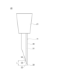
- FIG. 1 is a front view showing an injection needle assembly 20 to which the injection needle 11 of the present invention is applied.
- FIG. 2 is a schematic diagram showing a state in which the injection needle 11 of Embodiment 1 is punctured into the target site 100.
- FIG. 3(A) and 3(B) are a perspective view and a top view showing the injection needle 11 of Embodiment 1.
- FIG. 4(A) and 4(B) are a front view and a side view showing the injection needle 11 of Embodiment 1.
- FIG. 1 is a front view showing an injection needle assembly 20 to which the injection needle 11 of the present invention is applied.
- FIG. 2 is a schematic diagram showing a state in which the injection needle 11 of Embodiment 1 is punctured into the target site 100.
- FIG. 3(A) and 3(B) are a perspective view and a top view showing the injection needle 11 of Embodiment 1.
- FIG. 4(A) and 4(B) are a front view and a side view showing
- the injection needle assembly 20 has an injection needle 11 and a hub 21 that holds the proximal end of the injection needle 11 .
- a syringe (not shown) is connected to the proximal end of the hub 21 .
- the injection needle 11 is used to puncture the surface of the target site 100 such as mucosa or intradermally perpendicularly and inject the drug solution into the target site 100 .
- the term “perpendicular” refers not only to the case of forming an angle of 90 degrees with respect to the surface of the target site 100, but also to the surface of the target site 100 for the purpose of injecting the drug solution into the target site 100. Slightly slanting, substantially vertical cases are also included.
- the thickness dimension of the target site 100 such as mucous membrane or intradermal tissue differs depending on the specific tissue, but in the present invention, the target site is more than 0.1 mm and less than or equal to 2.0 mm.
- the injection needle 11 has a bevel-needle-shaped needle body 30 having a hollow portion 31 through which a drug solution can pass;
- a passage hole 33 is formed at the distal end of the needle 30 and allows the drug solution from the hollow portion 31 to pass therethrough.
- the passage hole 33 is arranged to be biased toward the side where the tip 34 of the needle body blade surface 32 is located.
- the edge of the opening edge of the passage hole 33 on the side opposite to the one-sided side is referred to as an "edge portion 35".
- a length L along the axial direction of the needle body 30 from the edge 35 to the tip 34 of the needle body blade surface 32 is 0.1 to less than 2.0 mm.
- the term "placed at one side” means that when an element is arranged on a member, the element is arranged eccentrically at a radially outward position with respect to the axis of the member.
- the passage hole 33 is arranged eccentrically at a radially outward position with respect to the axis of the needle body 30 .
- the passage hole 33 is eccentric to the side where the tip 34 of the needle blade surface 32 is located.
- the injection needle 11 can puncture the target site 100 without increasing the puncture resistance due to the needle body blade surface 32 formed at the tip of the needle body 30 .
- the passage hole 33 is arranged on the side where the tip 34 of the needle body blade surface 32 is located.
- a length L along the axial direction of the needle body 30 from the edge 35 of the passage hole 33 to the tip 34 of the needle body blade surface 32 is 0.1 to less than 2.0 mm.
- the tip 34 of the needle body blade surface 32 passes over the target site 100 and enters the tissue 101 below the target site 100. It can reduce sticking. This can prevent leakage of the liquid medicine to the underlying tissue 101 .
- the position of the passage hole 33 above the target site 100 can be reduced. As a result, leakage of the liquid medicine to the surface of the target site 100 can be prevented. Furthermore, since the needle body 30 having a relatively long needle body blade surface 32 (bevel length) can be used, the puncture resistance does not increase and the target site 100 can be punctured reliably.
- the injection needle 11 can puncture the target site 100 having a thickness of more than 0.1 mm and 2.0 mm or less without increasing the puncture resistance, and injects the drug solution into the target site 100 without causing leakage of the drug solution. be able to.
- the angle of the tip 34 of the needle blade surface 32 is preferably 30° or less. With this configuration, the target site 100 can be punctured without increasing the puncture resistance.
- the angle of the tip 34 of the needle blade surface 32 is preferably 10° or more.
- the lower limit that can be produced by grinding is about 5°, but the practical lower limit is 10° from the viewpoint of ease of grinding and mass productivity.
- the outer diameter of the needle body 30 is at least 0.20 mm or more. As the outer diameter of the needle body 30 becomes smaller, it becomes more difficult to grind the tip end 34 of the needle body blade surface 32 to an acute angle. As a result, the tip 34 of the needle body blade surface 32 has a relatively obtuse angle, increasing the puncture resistance. By setting the outer diameter of the needle 30 to 0.20 mm or more, it becomes easy to grind the tip 34 of the blade surface 32 of the needle to an acute angle. Therefore, the injection needle 11 can puncture the target site 100 without increasing the puncture resistance.
- the injection needle 11 of Embodiment 1 will be further detailed. As also shown in FIGS. 3(A), 3(B), 4(A) and 4(B), the injection needle 11 has a double tube needle structure.
- the needle body 30 has a first bevel needle 40 having a first lumen 41 and a first blade surface 42 , and a second lumen 51 and a second blade surface 52 within the first lumen 41 of the first bevel needle 40 . and a second bevel needle 50 housed in the .
- the hollow portion 31 described above is composed of the second lumen 51 of the second bevel needle 50 .
- the needle body blade surface 32 described above is composed of the first blade surface 42 of the first bevel needle 40 .
- the passage hole 33 described above is formed by the outlet 54 of the second lumen 51 of the second bevel needle 50 .
- the axial center of the needle body 30 described above corresponds to the axial center of the first bevel needle 40
- the axial direction of the needle body 30 corresponds to the axial direction of the first bevel needle 40 .
- the second bevel needle 50 has the second blade surface 52 directed in the same direction as the first blade surface 42 of the first bevel needle 40 .
- the second bevel needle 50 is further arranged to be biased toward the side where the tip 43 of the first blade surface 42 of the first bevel needle 40 is located.
- the arrangement position of the second bevel needle 50 can be restated as follows.
- the second bevel needle 50 is arranged radially outward with respect to the axis of the first bevel needle 40 and eccentrically on the side where the tip 43 of the first blade surface 42 of the first bevel needle 40 is located. there is
- the first lumen 41 of the first bevel needle 40 is sealed in the state where the second bevel needle 50 is arranged and does not pass liquid.
- the first lumen 41 is filled with a sealing material 44 (for example, a resin material) to seal the first lumen 41 .
- the sealing material 44 is removed beyond the first blade surface 42 of the first bevel needle 40 . Therefore, as shown in FIG. 2, the tip of the sealing material 44 does not extend beyond the first blade surface 42 of the first bevel needle 40 .
- the tip 53 of the second blade surface 52 of the second bevel needle 50 does not exceed the first blade surface 42 of the first bevel needle 40.
- the first blade surface 42 of the first bevel needle 40 contacts the target site 100 before the second blade surface 52 of the second bevel needle 50 .
- the injection needle 11 is punctured into the target site 100 by the first blade surface 42 of the first bevel needle 40 .
- the edge portion 35 is the edge of the opening edge of the discharge port 54 of the second lumen 51 of the second bevel needle 50 opposite to the one side.
- a length L along the axial direction of the first bevel needle 40 from the edge 35 to the tip 43 of the first blade surface 42 of the first bevel needle 40 is 0.1 to less than 2.0 mm.
- first bevel needle 40 and the second bevel needle 50 examples include stainless steel, aluminum, aluminum alloys, titanium, and titanium alloys.
- the first bevel needle 40 preferably has low puncture resistance.
- it is preferable to reduce the puncture resistance by coating the surface of the first bevel needle 40 with a coating agent made of silicone resin, fluororesin, or the like.
- the injection needle 11 having the above configuration can puncture the target site 100 having a thickness of more than 0.1 mm and 2.0 mm or less without increasing the puncture resistance, and injects the drug solution into the target site 100 without causing leakage of the drug solution. can do. Also, the injection needle 11 can be manufactured by combining the existing first bevel needle 40 and the existing second bevel needle 50 . Therefore, the injection needle 11 can be manufactured relatively easily and inexpensively.
- the second bevel needle 50 is arranged in contact with the inner peripheral surface 41 a of the first lumen 41 of the first bevel needle 40 .
- the discharge port 54 can be arranged most eccentrically, and positioning of the second bevel needle 50 with respect to the first bevel needle 40 is also facilitated.
- the thickness of the first bevel needle 40 is preferably thin. This is because the ejection port 54 can be further eccentrically arranged.
- the angle of the tip 43 of the first blade surface 42 of the first bevel needle 40 is sharper than the angle of the tip 53 of the second blade surface 52 of the second bevel needle 50 . Since the outer diameter of the first bevel needle 40 is larger than the outer diameter of the second bevel needle 50, it is easy to grind the tip 43 of the first blade surface 42 to an acute angle. Since the injection needle 11 is punctured into the target site 100 by the first blade surface 42 of the first bevel needle 40, the puncture resistance of the injection needle 11 is increased even if the second bevel needle 50 having a small outer diameter is used. never. As a result of being able to use a second bevel needle 50 with a smaller outer diameter, the outlet 54 can be positioned more eccentrically.
- the first bevel needle 40 has a needle tube of 27G (outer diameter 0.40 mm), inner diameter of 0.22 mm, and bevel length of the first blade surface 42 of 1.85 mm.
- the second bevel needle 50 has a needle tube of 36G (outer diameter 0.10 mm), inner diameter of 0.04 mm, and bevel length of the second blade surface 52 of 0.15 mm.
- the length L is approximately 0.3 mm.
- the target site 100 having a thickness of more than 0.1 mm and 2.0 mm or less can be punctured without increasing the puncture resistance, and the liquid medicine can be injected into the target site 100 without causing leakage of the liquid medicine. .
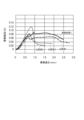
- FIG. 5 is a graph showing experimental results of the puncture resistance of the injection needle 11.
- the injection needle 11 of Embodiment 1 is a combination of the first bevel needle 40 and the second bevel needle 50 described above.
- the needle tube of Comparative Example 1 has a diameter of 27G (outer diameter 0.40 mm) and a bevel length of 1.85 mm.
- the needle tube of Comparative Example 2 has a diameter of 36G (outer diameter of 0.10 mm) and a bevel length of 0.52 mm.
- the needle tube of Comparative Example 3 has a diameter of 34G (outer diameter 0.20 mm) and a bevel length of 0.3 mm.
- the injection needle 11 of Embodiment 1 had a puncture resistance of about 0.082N.
- the needle tube of Comparative Example 1 had a puncture resistance of about 0.065N.
- the needle tube of Comparative Example 2 had a puncture resistance of about 0.073N.
- the needle tube of Comparative Example 3 had a puncture resistance of about 0.114N.
- the puncture resistance was slightly higher than that of the needle tube of Comparative Example 1.
- the reason for this is presumed to be a processing problem. That is, in Embodiment 1, the sealing material 44 partially adheres to the first blade surface 42 of the first bevel needle 40, and this is thought to increase the puncture resistance compared to Comparative Example 1.
- the injection needle 11 of Embodiment 1 had similar puncture resistance to the needle tube of Comparative Example 2 (36 G, bevel length 0.52 mm).
- the injection needle 11 of Embodiment 1 had a smaller puncture resistance than the needle tube of Comparative Example 3 (34 G, bevel length 0.3 mm).
- the injection needle 11 of Embodiment 1 is an injection needle 11 that punctures the surface of a target site 100 such as a mucous membrane or intracutaneously and injects a drug solution into the target site 100 .
- the injection needle 11 includes a bevel-needle-shaped needle body 30 having a hollow portion 31 through which a drug solution can pass; and a passage hole 33 that is formed at the tip of the and allows the chemical solution from the hollow portion 31 to pass through.
- the passage hole 33 is arranged to be biased toward the side where the tip 34 of the needle body blade surface 32 is located.
- the length L along the axial direction of the needle body 30 from the edge 35 of the opening edge of the passage hole 33 opposite to the one-sided side to the tip 34 of the needle body blade surface 32 is 0.1 to 2.0. less than 0 mm.
- the injection needle 11 configured in this way can puncture the target site 100 without increasing the puncture resistance due to the needle body blade surface 32 formed at the tip of the needle body 30 .
- the passage hole 33 is arranged on the side where the tip 34 of the needle body blade surface 32 is located.
- a length L along the axial direction of the needle body 30 from the edge 35 of the passage hole 33 to the tip 34 of the needle body blade surface 32 is 0.1 to less than 2.0 mm.
- the tip 34 of the needle body blade surface 32 passes over the target site 100 and enters the tissue 101 below the target site 100. It can reduce sticking. This can prevent leakage of the liquid medicine to the underlying tissue 101 .
- the position of the passage hole 33 above the target site 100 can be reduced. As a result, leakage of the liquid medicine to the surface of the target site 100 can be prevented. Furthermore, since the needle body 30 having a relatively long needle body blade surface 32 (bevel length) can be used, the puncture resistance does not increase and the target site 100 can be punctured reliably. Therefore, the injection needle 11 can puncture the target site 100 having a thickness of more than 0.1 mm and 2.0 mm or less without increasing the puncture resistance, and injects the drug solution into the target site 100 without causing leakage of the drug solution. can do.
- the angle of the tip 34 of the needle blade surface 32 is 30° or less. With this configuration, the target site 100 can be punctured without increasing the puncture resistance.
- the outer diameter of the needle body 30 is at least 0.20 mm or more.
- the needle body 30 has a first bevel needle 40 having a first lumen 41 and a first blade surface 42 , and a second lumen 51 and a second blade surface 52 within the first lumen 41 of the first bevel needle 40 . and a second bevel needle 50 housed in the .
- the hollow portion 31 is composed of the second lumen 51 of the second bevel needle 50
- the needle body cutting surface 32 is composed of the first cutting surface 42 of the first bevel needle 40
- the passage hole 33 is composed of the second bevel needle. It is composed of 50 second lumens 51 and outlets 54 .
- the second bevel needle 50 has the second blade surface 52 directed in the same direction as the first blade surface 42 of the first bevel needle 40, and the tip 43 of the first blade surface 42 of the first bevel needle 40 is positioned. placed to one side.
- the first lumen 41 of the first bevel needle 40 is sealed with the second bevel needle 50 placed thereon, and the tip 53 of the second blade surface 52 of the second bevel needle 50 is the first lumen 41 of the first bevel needle 40 .
- the injection needle 11 can puncture the target site 100 having a thickness of more than 0.1 mm and not more than 2.0 mm without increasing the puncture resistance, and the target site 100 can be prevented from leaking the drug solution.
- a drug solution can be injected inside.
- the injection needle 11 can be manufactured by combining the existing first bevel needle 40 and the existing second bevel needle 50 . Therefore, injection needle 11 can be manufactured relatively easily.
- the second bevel needle 50 is arranged in contact with the inner peripheral surface 41 a of the first lumen 41 of the first bevel needle 40 .
- the discharge port 54 can be arranged with the most eccentricity, and positioning of the second bevel needle 50 with respect to the first bevel needle 40 is facilitated.
- the angle of the tip 43 of the first blade surface 42 of the first bevel needle 40 is sharper than the angle of the tip 53 of the second blade surface 52 of the second bevel needle 50 .
- the outer diameter of the first bevel needle 40 is larger than the outer diameter of the second bevel needle 50, so it is easy to grind the tip 43 of the first blade surface 42 to an acute angle. . Since the injection needle 11 is punctured into the target site 100 by the first blade surface 42 of the first bevel needle 40, the puncture resistance of the injection needle 11 is increased even if the second bevel needle 50 having a small outer diameter is used. never. As a result of being able to use a second bevel needle 50 with a smaller outer diameter, the outlet 54 can be positioned more eccentrically.
- the first bevel needle 40 has a needle tube of 27G (outer diameter 0.40 mm), inner diameter of 0.22 mm, and bevel length of the first blade surface 42 of 1.85 mm.
- the second bevel needle 50 has a needle tube of 36G (outer diameter 0.10 mm), inner diameter of 0.04 mm, and bevel length of the second blade surface 52 of 0.15 mm.
- a needle tube of 27G (outer diameter 0.40 mm) is used as the first bevel needle 40 .
- a needle tube of 34G outer diameter: 0.20 mm, inner diameter: 0.16 mm, wall thickness: 0.02 mm
- the degree of deviation of the discharge port 54 of the second bevel needle 50 is reduced.
- the following embodiments can be adopted.
- FIG. 6(A), 6(B) and 6(C) are a cross-sectional view showing the injection needle 12 of Embodiment 2, a cross-sectional view and a top view along line 6B-6B in FIG. 6(A). .
- the injection needle 12 of Embodiment 2 is similar to the injection needle 11 of Embodiment 1, and has a bevel needle-shaped needle body 30 having a hollow portion 31 through which a drug solution can pass, and a needle body 30 formed at the tip of the needle body 30. It has a needle body blade surface 32 that can pierce the target site 100 and a passage hole 33 that is formed at the tip of the needle body 30 and allows the drug solution from the hollow part 31 to pass therethrough.
- the passage hole 33 is arranged to be biased toward the side where the tip 34 of the needle body blade surface 32 is located.
- the length L along the axial direction of the needle body from the edge 35 of the opening edge of the passage hole 33 opposite to the one-sided side to the tip 34 of the needle body blade surface 32 is 0.1 to 2.0 mm. is less than
- the injection needle 12 of Embodiment 2 can also puncture the target site 100 having a thickness of more than 0.1 mm and 2.0 mm or less without increasing the puncture resistance, and the drug solution can be injected into the target site 100 without causing leakage of the drug solution. can be injected.
- the angle of the tip 34 of the needle blade surface 32 is 30° or less.
- the needle body 30 has an outer diameter of at least 0.20 mm.
- the needle body 30 is made of a metal material.
- metal materials include stainless steel, aluminum, aluminum alloys, titanium, and titanium alloys.
- the hollow portion 31 and the passage hole 33 described above are composed of a lumen 60 parallel to the axial direction of the needle 30 .
- the lumen 60 is formed by subjecting a solid metal material to, for example, laser machining or electrical discharge machining.
- the needle body 30 By arranging the lumen 60 to one side, the needle body 30 has a thick compressed region 61 (a region above the lumen 60 in FIG. 6A) and a thin region 62 with a small thickness (FIG. 6A). ) below the lumen 60).
- the thickness of the thinned region 62 is at least 0.02 mm or more.
- the injection needle 12 of Embodiment 2 has an uneven thickness needle structure in which a thickened area 61 and a thinned area 62 are formed. Although it is possible to arrange the lumen 60 on the axis and form a needle tube with a small outer diameter, it is not possible to secure the needle strength required for puncture. In addition, the blade surface cannot be created by grinding. Although the blade surface can be machined by electroforming or electric discharge machining, the puncture resistance can be lowered by grinding the blade surface. Therefore, by making the injection needle 12 into a needle structure with a reduced thickness, it is possible to secure the needle strength necessary for puncturing. Moreover, since the needle body blade surface 32 can be produced by grinding, the injection needle 12 with low puncture resistance can be formed.
- the reason why the thickness of the thin region 62 is set to at least 0.02 mm or more is to ensure the strength of the needle necessary for puncturing and to enable the needle body blade surface 32 to be produced by grinding.
- the needle body 30 is made of a metal material, and the hollow portion 31 and the passage hole 33 are configured by the lumen 60 parallel to the axial direction of the needle body 30. .
- the needle body 30 is formed with a compressed region 61 having a large thickness and a thin region 62 having a small thickness.
- the thickness of the thinned region 62 is at least 0.02 mm or more.
- the injection needle 12 of Embodiment 2 can also puncture the target site 100 having a thickness of more than 0.1 mm and 2.0 mm or less without increasing the puncture resistance, and the drug solution can be injected into the target site 100 without causing leakage of the drug solution. can be injected.
- the needle strength required for puncturing can be ensured, and the needle body blade surface 32 can be formed by grinding, so that the injection needle 12 with low puncture resistance can be formed.
- FIG. 3 are a cross-sectional view showing the injection needle 13 of Embodiment 3, a cross-sectional view and a top view along line 7B-7B in FIG. 7(A).
- 8(A), 8(B) and 8(C) are schematic diagrams showing the procedure for forming the injection needle 13 of Embodiment 3.
- FIG. Members common to the injection needles 11 and 12 of Embodiments 1 and 2 are denoted by the same reference numerals, and descriptions thereof are partially omitted.
- the needle body 30 is made of a metal material.
- metal materials include stainless steel, aluminum, aluminum alloys, titanium, and titanium alloys.
- the hollow portion 31 described above is composed of a lumen 70 that is concentric with the axis of the needle body 30 .
- the needle body 30 has a thickness of at least 0.02 mm.
- a pipe 71 having a lumen 70 is manufactured by electroforming.
- the needle blade face 32 is created by grinding.
- a passage hole 33 is formed at the tip of the needle body 30 by electric discharge machining or laser machining.
- the thickness of the needle body 30 is set to at least 0.02 mm or more because, as with the injection needle 12 of Embodiment 2, the strength of the needle required for puncturing is ensured, and the blade surface 32 of the needle body is created by grinding. This is to make it possible.
- the needle body 30 is made of a metal material, and the hollow part 31 is composed of the inner lumen 70 concentric with the axis of the needle body 30 .
- the needle body 30 has a thickness of at least 0.02 mm.
- the injection needle 13 of Embodiment 3 can also puncture the target site 100 having a thickness of more than 0.1 mm and 2.0 mm or less without increasing the puncture resistance, and the drug solution can be injected into the target site 100 without causing leakage of the drug solution. can be injected.
- the needle strength required for puncturing can be ensured, and the needle body blade surface 32 can be formed by grinding, so that the injection needle 12 with low puncture resistance can be formed.
- FIG. 10(A), 10(B) and 10(C) are schematic diagrams showing the procedure for forming the injection needle 14 of the fourth embodiment.
- the members common to the injection needles 11 to 13 of Embodiments 1 to 3 are denoted by the same reference numerals, and the description thereof is partially omitted.
- the injection needle 14 of Embodiment 4 has a small diameter portion 80 on the distal end side and a large diameter portion 81 on the proximal end side.
- the small diameter portion 80 of the injection needle 12 is configured similarly to the injection needle 12 of the second embodiment.
- the needle body 30 has a thick compressed region 61 (a region above the lumen 60 in FIG. 9(C)) and a thin region 62 (FIG. 9(C)). ) below the lumen 60).
- the thickness of the thinned region 62 is at least 0.02 mm or more.
- the lumen 60 of the large-diameter portion 81 of the injection needle 12 is arranged close to the axis.
- a thick-walled pipe 82 having a lumen 60 formed at its axis is prepared.
- one side (below the lumen 60) of the thick pipe 82 is shaved by electric discharge machining or polishing to form a thin region 62. As shown in FIG. 10(B), one side (below the lumen 60) of the thick pipe 82 is shaved by electric discharge machining or polishing to form a thin region 62. As shown in FIG. 10(B), one side (below the lumen 60) of the thick pipe 82 is shaved by electric discharge machining or polishing to form a thin region 62. As shown in FIG.
- the needle blade surface 32 is created by grinding.
- the reason why the thickness of the thin region 62 is set to at least 0.02 mm or more is to ensure the strength of the needle necessary for puncturing and to enable the needle body blade surface 32 to be produced by grinding.
- the injection needle 14 of Embodiment 4 can also puncture the target site 100 with a thickness of more than 0.1 mm and 2.0 mm or less without increasing the puncture resistance, and the drug solution can be injected into the target site 100 without causing leakage of the drug solution. can be injected. Furthermore, the needle strength required for puncturing can be ensured, and the needle body blade surface 32 can be formed by grinding, so that the injection needle 12 with low puncture resistance can be formed.
- Embodiment 5 modifies the procedure for forming injection needle 15 having a biased thickness needle structure (structure similar to injection needle 12 of Embodiment 2).
- 11(A) and 11(B) are schematic diagrams showing the procedure for forming the injection needle 15 of the fifth embodiment.
- a pipe 90 in which the lumens 60 are arranged side by side is produced by electroforming. Lumen 60 does not pass through pipe 90 .
- the needle blade face 32 is created by grinding until the lumen 60 appears.
- the injection needle 12 of Embodiment 5 can also puncture the target site 100 with a thickness of more than 0.1 mm and 2.0 mm or less without increasing the puncture resistance, and the drug solution can be injected into the target site 100 without causing leakage of the drug solution. can be injected. Furthermore, the needle strength required for puncturing can be ensured, and the needle body blade surface 32 can be formed by grinding, so that the injection needle 12 with low puncture resistance can be formed.
- the injection needles 11 to 15 according to the present invention have been described through Embodiments 1 to 5, but the present invention is not limited only to the contents described in the embodiments. It is possible to change.
- the angle of the tip 43 of the first blade surface 42 of the first bevel needle 40 is assumed to be sharper than the angle of the tip 53 of the second blade surface 52 of the second bevel needle 50 .
- the invention is not limited to this case.
- the angle of the tip 43 of the first blade surface 42 and the angle of the tip 53 of the second blade surface 52 are made the same angle, so that the first blade surface 42 and the second blade surface 52 can be aligned.
- Injection needle assembly 21 Hub 30 Needle 31 Hollow portion 32 Needle blade surface 33 Passing hole 34 Tip 35 Edge 40 First bevel needle 41 First lumen 41a Inner peripheral surface 42 First blade surface 43 Tip 44 Sealing material 50 Second bevel needle 51 Second lumen 52 Second blade surface 53 Tip 54 Discharge port 60 Lumen 61 Thickened region 62 Thin region 70 Lumen 71 Pipe 80 Small diameter portion 81 Large diameter portion 82 Thick pipe 90 Pipe 100 Target site 101 Underlying tissue
Abstract
[Problem] To provide an injection needle that can pierce a target site such as a mucosa or intradermal area without increasing piercing resistance and that can inject a drug solution into the target site without causing leakage of the drug solution. [Solution] An injection needle 11 that pierces perpendicularly the surface of a target site 100 such as a mucosa or intradermal area and injects a drug solution into the target site. The injection needle comprises a bevel needle-shaped needle body 30 having a hollow section 31 through which a drug solution can pass, a needle blade surface 32 which is formed at the tip of the needle body and can pierce the target site, and a passage hole 33 which is formed at the tip of the needle body and allows the drug solution from the hollow section to pass. The passage hole is positioned closer to the side where the tip 34 of the needle blade surface is located. The length L along the axial direction of the needle body from an edge 35, said edge being opposite to the aforesaid closer side, of the opening periphery of the passage hole to the tip of the needle blade surface is from 0.1 mm to less than 2.0 mm.
Description
本発明は、注射針に関する。
The present invention relates to injection needles.
第1針と、第1針のルーメン内に収納される第2針とを有する医療用デバイスが知られている(特許文献1を参照)。第2針は、第1針の軸心に対して径方向外方に偏心して配置される。第2針は、第1針のルーメンの内壁によってガイドされつつスライド移動自在である。第2針のルーメンの少なくとも先端は、第1針の軸心に近接するように、第2針が偏心した側とは反対側に偏心して配置される。この医療用デバイスは、第1針を血管に穿刺した後、第2針を第1針から露出させて、第2針のルーメン先端から生分解性材料を注入する。生分解性材料を血管の外周に配置することによって、静脈注射を行うにあたって、薬液の血管外漏出を防いでいる。
A medical device having a first needle and a second needle housed within the lumen of the first needle is known (see Patent Document 1). The second needle is arranged eccentrically radially outwardly with respect to the axis of the first needle. The second needle is slidable while being guided by the inner wall of the lumen of the first needle. At least the tip of the lumen of the second needle is eccentrically arranged on the side opposite to the eccentric side of the second needle so as to be close to the axis of the first needle. This medical device punctures the blood vessel with the first needle, then exposes the second needle from the first needle, and injects the biodegradable material from the tip of the lumen of the second needle. By placing biodegradable material around the circumference of the blood vessel, extravasation of the drug solution is prevented during intravenous injection.
ところで、粘膜や皮内などの著しく薄い目的部位に薬液を注入するために、注射針を目的部位の表面に対して垂直に穿刺して使用することがある。汎用的な注射針の刃面は、斜めに傾斜した形状(ベベル針形状)を有する。このため、刃面の先端が目的部位を越えて目的部位よりも下層の組織に突き刺さり、下層組織への薬液漏れが生じる恐れがある。また、刃面の先端が目的部位を越えないものの、ルーメン先端が目的部位よりも上方に位置し、目的部位の表面への薬液漏れが生じる恐れがある。さらに、刃面の長さ(ベベル長)が短いいわゆる鈍角針の場合には、穿刺抵抗が上昇し目的部位への穿刺を達成できない恐れがある。
By the way, in order to inject a drug solution into a remarkably thin target site such as a mucous membrane or intradermal skin, an injection needle may be used by vertically piercing the surface of the target site. A blade surface of a general-purpose injection needle has an obliquely inclined shape (beveled needle shape). For this reason, the tip of the blade face may go beyond the target site and pierce the tissue underlying the target site, causing the liquid medicine to leak into the underlying tissue. In addition, although the tip of the blade face does not exceed the target site, the tip of the lumen is located above the target site, and there is a risk that the liquid medicine will leak to the surface of the target site. Furthermore, in the case of a so-called obtuse-angled needle having a short blade surface (bevel length), the puncture resistance increases, and there is a risk that the target site cannot be punctured.
特許文献1に開示された医療用デバイスを目的部位の表面に対して垂直に穿刺して使用したとしても、第2針のルーメン先端が第1針の軸心に近接して位置する。このため、上述した下層組織への薬液漏れなどの課題が生じる。
Even if the medical device disclosed in Patent Document 1 is used by puncturing the surface of the target site perpendicularly, the lumen tip of the second needle is positioned close to the axis of the first needle. For this reason, problems such as leakage of the liquid medicine to the underlying tissue as described above arise.
そこで本発明は、粘膜や皮内などの目的部位に穿刺抵抗を上昇させることなく穿刺でき、薬液漏れを生じることなく目的部位内に薬液を注入することが可能な注射針を提供することを目的とする。
SUMMARY OF THE INVENTION Accordingly, an object of the present invention is to provide an injection needle capable of puncturing a target site such as a mucous membrane or intradermal without increasing the puncture resistance and injecting a drug solution into the target site without causing leakage of the drug solution. and
本発明に係る注射針は、粘膜や皮内などの目的部位の表面に対して垂直に穿刺し、前記目的部位内に薬液を注入する注射針である。注射針は、前記薬液が通過可能な中空部を有するベベル針形状の針体と、前記針体の先端部に形成され前記目的部位に穿刺可能な針体刃面と、前記針体の先端部に形成され前記中空部からの前記薬液を通過させる通過穴と、を有する。前記通過穴は、前記針体刃面の先端が位置する側に片寄せて配置されている。前記通過穴の開口縁のうち片寄せた側とは反対側の縁部から、前記針体刃面の前記先端までの前記針体の軸方向に沿う長さが0.1~2.0mm未満である。
The injection needle according to the present invention is an injection needle that punctures the surface of a target site such as a mucous membrane or intradermally perpendicularly to inject a drug solution into the target site. The injection needle comprises a bevel-needle-shaped needle body having a hollow portion through which the drug solution can pass, a needle body blade surface formed at the distal end portion of the needle body and capable of puncturing the target site, and a distal end portion of the needle body. and a passage hole through which the chemical solution from the hollow portion passes. The passage hole is arranged to be biased toward the side where the tip of the blade surface of the needle body is located. The length along the axial direction of the needle body from the edge of the opening edge of the passage hole opposite to the one-sided side to the tip of the blade face of the needle body is 0.1 to less than 2.0 mm. is.
本発明に係る注射針は、通過穴が針体刃面の先端が位置する側に片寄せて配置されている。さらに、通過穴の縁部から、針体刃面の先端までの針体の軸方向に沿う長さが0.1~2.0mm未満である。ベベル針形状の針体の軸心の位置に通過穴を配置する場合に比較して、針体刃面の先端が目的部位を越えて目的部位よりも下層の組織に突き刺さることを低減できる。これにより、下層組織への薬液漏れを防止できる。また、通過穴が目的部位よりも上方に位置することを低減できる。これにより、目的部位の表面への薬液漏れを防止できる。さらに、針体刃面の長さ(ベベル長)が比較的長い針体を使用できるため、穿刺抵抗が上昇せず目的部位への穿刺を確実に達成できる。したがって、注射針は、厚み寸法が0.1mmを超え、2.0mm以下の目的部位に穿刺抵抗を上昇させることなく穿刺でき、薬液漏れを生じることなく目的部位内に薬液を注入することができる。
In the injection needle according to the present invention, the passage hole is arranged on the side where the tip of the blade surface of the needle body is located. Further, the length along the axial direction of the needle body from the edge of the passage hole to the tip of the blade surface of the needle body is 0.1 to less than 2.0 mm. Compared to the case where the passage hole is arranged at the position of the axis of the bevel needle-shaped needle body, it is possible to reduce the possibility that the tip of the blade face of the needle body passes over the target site and pierces the tissue underlying the target site. This can prevent leakage of the liquid medicine to the underlying tissue. Moreover, it is possible to reduce the position of the passage hole above the target site. As a result, it is possible to prevent the liquid medicine from leaking onto the surface of the target site. Furthermore, since a needle body having a relatively long needle body blade surface length (bevel length) can be used, the puncture resistance does not increase and the target site can be punctured reliably. Therefore, the injection needle can puncture a target site with a thickness of more than 0.1 mm and 2.0 mm or less without increasing the puncture resistance, and can inject the drug solution into the target site without causing leakage of the drug solution. .
以下、添付した図面を参照して、本発明の実施形態を説明する。なお、図面の説明において同一の要素には同一の符号を付し、重複する説明を省略する。また、図面の寸法比率は、説明の都合上誇張され、実際の比率とは異なる場合がある。
Hereinafter, embodiments of the present invention will be described with reference to the attached drawings. In the description of the drawings, the same elements are denoted by the same reference numerals, and overlapping descriptions are omitted. Also, the dimensional ratios in the drawings are exaggerated for convenience of explanation and may differ from the actual ratios.
なお、本明細書では、目的部位100に穿刺する側を「先端」または「先端側」、反対側を「基端」または「基端側」と称する。また、先端およびその周辺部分を含む一定の範囲を示す部分を「先端部」と称する。また、注射針の針体30が伸びている方向を「軸方向」と称する。
In this specification, the side where the target site 100 is punctured is called "distal end" or "distal end side", and the opposite side is called "proximal end" or "proximal end side". Also, a portion showing a certain range including the tip and its peripheral portion is referred to as a "tip". Also, the direction in which the needle body 30 of the injection needle extends is referred to as the "axial direction".
(実施形態1)
図1は、本発明の注射針11を適用した注射針組立体20を示す正面図である。図2は、実施形態1の注射針11を目的部位100に穿刺した状態において示す模式図である。図3(A)および図3(B)は、実施形態1の注射針11を示す斜視図および上面図である。図4(A)および図4(B)は、実施形態1の注射針11を示す正面図および側面図である。 (Embodiment 1)
FIG. 1 is a front view showing aninjection needle assembly 20 to which the injection needle 11 of the present invention is applied. FIG. 2 is a schematic diagram showing a state in which the injection needle 11 of Embodiment 1 is punctured into the target site 100. As shown in FIG. 3(A) and 3(B) are a perspective view and a top view showing the injection needle 11 of Embodiment 1. FIG. 4(A) and 4(B) are a front view and a side view showing the injection needle 11 of Embodiment 1. FIG.
図1は、本発明の注射針11を適用した注射針組立体20を示す正面図である。図2は、実施形態1の注射針11を目的部位100に穿刺した状態において示す模式図である。図3(A)および図3(B)は、実施形態1の注射針11を示す斜視図および上面図である。図4(A)および図4(B)は、実施形態1の注射針11を示す正面図および側面図である。 (Embodiment 1)
FIG. 1 is a front view showing an
図1に示すように、注射針組立体20は、注射針11と、注射針11の基端を保持するハブ21と、を有する。ハブ21の基端に図示しないシリンジが接続される。
As shown in FIG. 1 , the injection needle assembly 20 has an injection needle 11 and a hub 21 that holds the proximal end of the injection needle 11 . A syringe (not shown) is connected to the proximal end of the hub 21 .
図2に示すように、注射針11は、粘膜や皮内などの目的部位100の表面に対して垂直に穿刺され、目的部位100内に薬液を注入するために使用される。本明細書において「垂直」とは、目的部位100の表面に対して90度の角度をなす場合のみならず、目的部位100内に薬液を注入する目的のために目的部位100の表面に対してやや傾斜する略垂直の場合も含まれるものとする。
As shown in FIG. 2, the injection needle 11 is used to puncture the surface of the target site 100 such as mucosa or intradermally perpendicularly and inject the drug solution into the target site 100 . In this specification, the term “perpendicular” refers not only to the case of forming an angle of 90 degrees with respect to the surface of the target site 100, but also to the surface of the target site 100 for the purpose of injecting the drug solution into the target site 100. Slightly slanting, substantially vertical cases are also included.
粘膜や皮内などの目的部位100の厚み寸法は、具体的な組織によって異なるが、本発明においては0.1mmを超え、2.0mm以下の部位を適用対象としている。
The thickness dimension of the target site 100 such as mucous membrane or intradermal tissue differs depending on the specific tissue, but in the present invention, the target site is more than 0.1 mm and less than or equal to 2.0 mm.
注射針11は、概説すると、薬液が通過可能な中空部31を有するベベル針形状の針体30と、針体30の先端部に形成され目的部位100に穿刺可能な針体刃面32と、針体30の先端部に形成され中空部31からの薬液を通過させる通過穴33と、を有する。通過穴33は、針体刃面32の先端34が位置する側に片寄せて配置されている。通過穴33の開口縁のうち片寄せた側とは反対側の縁を、「縁部35」と称する。縁部35から、針体刃面32の先端34までの針体30の軸方向に沿う長さLが0.1~2.0mm未満である。
In general, the injection needle 11 has a bevel-needle-shaped needle body 30 having a hollow portion 31 through which a drug solution can pass; A passage hole 33 is formed at the distal end of the needle 30 and allows the drug solution from the hollow portion 31 to pass therethrough. The passage hole 33 is arranged to be biased toward the side where the tip 34 of the needle body blade surface 32 is located. The edge of the opening edge of the passage hole 33 on the side opposite to the one-sided side is referred to as an "edge portion 35". A length L along the axial direction of the needle body 30 from the edge 35 to the tip 34 of the needle body blade surface 32 is 0.1 to less than 2.0 mm.
本明細書において、「片寄せて配置」とは、ある部材にある要素を配置するとき、部材の軸心に対して径方向外方の位置に偏心して要素を配置することを意味する。上記の通過穴33を例に挙げると、通過穴33は、針体30の軸心に対して径方向外方の位置に偏心して配置されている。特に、通過穴33は、針体刃面32の先端34が位置する側に偏心している。
In this specification, the term "placed at one side" means that when an element is arranged on a member, the element is arranged eccentrically at a radially outward position with respect to the axis of the member. Taking the above-described passage hole 33 as an example, the passage hole 33 is arranged eccentrically at a radially outward position with respect to the axis of the needle body 30 . In particular, the passage hole 33 is eccentric to the side where the tip 34 of the needle blade surface 32 is located.
注射針11は、針体30の先端部に形成した針体刃面32によって目的部位100に穿刺抵抗を上昇させることなく穿刺できる。通過穴33が針体刃面32の先端34が位置する側に片寄せて配置されている。通過穴33の上記の縁部35から、針体刃面32の先端34までの針体30の軸方向に沿う長さLが0.1~2.0mm未満である。ベベル針形状の針体30の軸心の位置に通過穴33を配置する場合に比較して、針体刃面32の先端34が目的部位100を越えて目的部位100よりも下層の組織101に突き刺さることを低減できる。これにより、下層の組織101への薬液漏れを防止できる。また、通過穴33が目的部位100よりも上方に位置することを低減できる。これにより、目的部位100の表面への薬液漏れを防止できる。さらに、針体刃面32の長さ(ベベル長)が比較的長い針体30を使用できるため、穿刺抵抗が上昇せず目的部位100への穿刺を確実に達成できる。
The injection needle 11 can puncture the target site 100 without increasing the puncture resistance due to the needle body blade surface 32 formed at the tip of the needle body 30 . The passage hole 33 is arranged on the side where the tip 34 of the needle body blade surface 32 is located. A length L along the axial direction of the needle body 30 from the edge 35 of the passage hole 33 to the tip 34 of the needle body blade surface 32 is 0.1 to less than 2.0 mm. Compared to the case where the passage hole 33 is arranged at the position of the axis of the bevel needle-shaped needle body 30, the tip 34 of the needle body blade surface 32 passes over the target site 100 and enters the tissue 101 below the target site 100. It can reduce sticking. This can prevent leakage of the liquid medicine to the underlying tissue 101 . Also, the position of the passage hole 33 above the target site 100 can be reduced. As a result, leakage of the liquid medicine to the surface of the target site 100 can be prevented. Furthermore, since the needle body 30 having a relatively long needle body blade surface 32 (bevel length) can be used, the puncture resistance does not increase and the target site 100 can be punctured reliably.
したがって、注射針11は、厚み寸法が0.1mmを超え、2.0mm以下の目的部位100に穿刺抵抗を上昇させることなく穿刺でき、薬液漏れを生じることなく目的部位100内に薬液を注入することができる。
Therefore, the injection needle 11 can puncture the target site 100 having a thickness of more than 0.1 mm and 2.0 mm or less without increasing the puncture resistance, and injects the drug solution into the target site 100 without causing leakage of the drug solution. be able to.
針体刃面32の先端34の角度は、30°以下であることが好ましい。このように構成することによって、目的部位100に穿刺抵抗を上昇させることなく穿刺できる。針体刃面32の先端34の角度は、10°以上であることが好ましい。研削加工によって作成できる下限は約5°であるが、研削加工の容易性および量産性などの観点から、現実的な下限は10°である。
The angle of the tip 34 of the needle blade surface 32 is preferably 30° or less. With this configuration, the target site 100 can be punctured without increasing the puncture resistance. The angle of the tip 34 of the needle blade surface 32 is preferably 10° or more. The lower limit that can be produced by grinding is about 5°, but the practical lower limit is 10° from the viewpoint of ease of grinding and mass productivity.
針体30の外径は、少なくとも、0.20mm以上である。針体30の外径が小径になるほど、針体刃面32の先端34を鋭角に研削加工することが困難になる。このため、針体刃面32の先端34が比較的鈍角になり、穿刺抵抗が大きくなる。針体30の外径を0.20mm以上とすることによって、針体刃面32の先端34を鋭角に研削加工することが容易になる。したがって、注射針11は、目的部位100に穿刺抵抗を上昇させることなく穿刺できる。
The outer diameter of the needle body 30 is at least 0.20 mm or more. As the outer diameter of the needle body 30 becomes smaller, it becomes more difficult to grind the tip end 34 of the needle body blade surface 32 to an acute angle. As a result, the tip 34 of the needle body blade surface 32 has a relatively obtuse angle, increasing the puncture resistance. By setting the outer diameter of the needle 30 to 0.20 mm or more, it becomes easy to grind the tip 34 of the blade surface 32 of the needle to an acute angle. Therefore, the injection needle 11 can puncture the target site 100 without increasing the puncture resistance.
実施形態1の注射針11をさらに詳述する。図3(A)、図3(B)、図4(A)および図4(B)にも示すように、注射針11は、二重管針構造を有する。針体30は、第1ルーメン41と第1刃面42とを有する第1ベベル針40と、第2ルーメン51と第2刃面52とを有し第1ベベル針40の第1ルーメン41内に収納される第2ベベル針50とを有する。
The injection needle 11 of Embodiment 1 will be further detailed. As also shown in FIGS. 3(A), 3(B), 4(A) and 4(B), the injection needle 11 has a double tube needle structure. The needle body 30 has a first bevel needle 40 having a first lumen 41 and a first blade surface 42 , and a second lumen 51 and a second blade surface 52 within the first lumen 41 of the first bevel needle 40 . and a second bevel needle 50 housed in the .
上述の中空部31は、第2ベベル針50の第2ルーメン51から構成されている。上述の針体刃面32は、第1ベベル針40の第1刃面42から構成されている。上述の通過穴33は、第2ベベル針50の第2ルーメン51の吐出口54から構成されている。上述の針体30の軸心は、第1ベベル針40の軸心に相当し、針体30の軸方向は、第1ベベル針40の軸方向に相当する。
The hollow portion 31 described above is composed of the second lumen 51 of the second bevel needle 50 . The needle body blade surface 32 described above is composed of the first blade surface 42 of the first bevel needle 40 . The passage hole 33 described above is formed by the outlet 54 of the second lumen 51 of the second bevel needle 50 . The axial center of the needle body 30 described above corresponds to the axial center of the first bevel needle 40 , and the axial direction of the needle body 30 corresponds to the axial direction of the first bevel needle 40 .
第2ベベル針50は、第2刃面52が第1ベベル針40の第1刃面42と同じ向きに向けられている。第2ベベル針50はさらに、第1ベベル針40の第1刃面42の先端43が位置する側に片寄せて配置されている。第2ベベル針50の配置位置は次のとおり換言される。第2ベベル針50は、第1ベベル針40の軸心に対して径方向外方であって、第1ベベル針40の第1刃面42の先端43が位置する側に偏心して配置されている。
The second bevel needle 50 has the second blade surface 52 directed in the same direction as the first blade surface 42 of the first bevel needle 40 . The second bevel needle 50 is further arranged to be biased toward the side where the tip 43 of the first blade surface 42 of the first bevel needle 40 is located. The arrangement position of the second bevel needle 50 can be restated as follows. The second bevel needle 50 is arranged radially outward with respect to the axis of the first bevel needle 40 and eccentrically on the side where the tip 43 of the first blade surface 42 of the first bevel needle 40 is located. there is
第1ベベル針40の第1ルーメン41は、第2ベベル針50を配置した状態において封止され、通液しない。第2ベベル針50を第1ベベル針40内に配置した後、第1ルーメン41に封止材料44(例えば、樹脂材料)を注入充填して、第1ルーメン41を封止する。封止材料44は第1ベベル針40の第1刃面42を越えた部分が除去される。したがって、図2に示すように、封止材料44の先端部は、第1ベベル針40の第1刃面42を越えない。
The first lumen 41 of the first bevel needle 40 is sealed in the state where the second bevel needle 50 is arranged and does not pass liquid. After placing the second beveled needle 50 inside the first beveled needle 40 , the first lumen 41 is filled with a sealing material 44 (for example, a resin material) to seal the first lumen 41 . The sealing material 44 is removed beyond the first blade surface 42 of the first bevel needle 40 . Therefore, as shown in FIG. 2, the tip of the sealing material 44 does not extend beyond the first blade surface 42 of the first bevel needle 40 .
図2および図4(B)に示すように、第2ベベル針50の第2刃面52の先端53は、第1ベベル針40の第1刃面42を越えない。注射針11は、目的部位100に穿刺するとき、第1ベベル針40の第1刃面42が第2ベベル針50の第2刃面52よりも先に目的部位100に接触する。注射針11は、第1ベベル針40の第1刃面42によって目的部位100に穿刺される。
As shown in FIGS. 2 and 4(B), the tip 53 of the second blade surface 52 of the second bevel needle 50 does not exceed the first blade surface 42 of the first bevel needle 40. When the injection needle 11 punctures the target site 100 , the first blade surface 42 of the first bevel needle 40 contacts the target site 100 before the second blade surface 52 of the second bevel needle 50 . The injection needle 11 is punctured into the target site 100 by the first blade surface 42 of the first bevel needle 40 .
図2に示すように、縁部35は、第2ベベル針50の第2ルーメン51の吐出口54の開口縁のうち片寄せた側とは反対側の縁である。縁部35から、第1ベベル針40の第1刃面42の先端43までの第1ベベル針40の軸方向に沿う長さLが0.1~2.0mm未満である。
As shown in FIG. 2, the edge portion 35 is the edge of the opening edge of the discharge port 54 of the second lumen 51 of the second bevel needle 50 opposite to the one side. A length L along the axial direction of the first bevel needle 40 from the edge 35 to the tip 43 of the first blade surface 42 of the first bevel needle 40 is 0.1 to less than 2.0 mm.
第1ベベル針40および第2ベベル針50の材料としては、例えば、ステンレス鋼、アルミニウム、アルミニウム合金、チタン、チタン合金などが用いられる。第1ベベル針40は、穿刺抵抗が小さいものが好ましい。例えば、第1ベベル針40の表面に、シリコーン樹脂やフッ素形樹脂等からなるコーティング剤をコーティングすることによって、穿刺抵抗を低減することが好ましい。
Examples of materials used for the first bevel needle 40 and the second bevel needle 50 include stainless steel, aluminum, aluminum alloys, titanium, and titanium alloys. The first bevel needle 40 preferably has low puncture resistance. For example, it is preferable to reduce the puncture resistance by coating the surface of the first bevel needle 40 with a coating agent made of silicone resin, fluororesin, or the like.
上記構成の注射針11は、厚み寸法が0.1mmを超え、2.0mm以下の目的部位100に穿刺抵抗を上昇させることなく穿刺でき、薬液漏れを生じることなく目的部位100内に薬液を注入することができる。また、注射針11は、現存する第1ベベル針40と現存する第2ベベル針50とを組み合わせることによって製造できる。したがって、注射針11を比較的容易かつ安価に製造できる。
The injection needle 11 having the above configuration can puncture the target site 100 having a thickness of more than 0.1 mm and 2.0 mm or less without increasing the puncture resistance, and injects the drug solution into the target site 100 without causing leakage of the drug solution. can do. Also, the injection needle 11 can be manufactured by combining the existing first bevel needle 40 and the existing second bevel needle 50 . Therefore, the injection needle 11 can be manufactured relatively easily and inexpensively.
第2ベベル針50は、第1ベベル針40の第1ルーメン41の内周面41aに接触して配置される。吐出口54を最も偏心して配置でき、第1ベベル針40に対する第2ベベル針50の位置決めも容易になる。この配置の場合には、第1ベベル針40の肉厚は、薄肉であることが好ましい。吐出口54をさらに偏心させて配置できるからである。
The second bevel needle 50 is arranged in contact with the inner peripheral surface 41 a of the first lumen 41 of the first bevel needle 40 . The discharge port 54 can be arranged most eccentrically, and positioning of the second bevel needle 50 with respect to the first bevel needle 40 is also facilitated. In this arrangement, the thickness of the first bevel needle 40 is preferably thin. This is because the ejection port 54 can be further eccentrically arranged.
第1ベベル針40の第1刃面42の先端43の角度は、第2ベベル針50の第2刃面52の先端53の角度よりも鋭角である。第1ベベル針40の外径は第2ベベル針50の外径よりも大きいことから、第1刃面42の先端43を鋭角に研削加工することが容易である。注射針11は第1ベベル針40の第1刃面42によって目的部位100に穿刺されることから、外径が小さい第2ベベル針50を使用しても、注射針11の穿刺抵抗が大きくなることはない。外径が小さい第2ベベル針50を使用できる結果、吐出口54をさらに偏心して配置することができる。
The angle of the tip 43 of the first blade surface 42 of the first bevel needle 40 is sharper than the angle of the tip 53 of the second blade surface 52 of the second bevel needle 50 . Since the outer diameter of the first bevel needle 40 is larger than the outer diameter of the second bevel needle 50, it is easy to grind the tip 43 of the first blade surface 42 to an acute angle. Since the injection needle 11 is punctured into the target site 100 by the first blade surface 42 of the first bevel needle 40, the puncture resistance of the injection needle 11 is increased even if the second bevel needle 50 having a small outer diameter is used. never. As a result of being able to use a second bevel needle 50 with a smaller outer diameter, the outlet 54 can be positioned more eccentrically.
第1ベベル針40と第2ベベル針50との組み合わせの一例を挙げると次のとおりである。第1ベベル針40は、27G(外径0.40mm)、内径が0.22mm、第1刃面42のベベル長が1.85mmの針管を有する。第2ベベル針50は、36G(外径0.10mm)、内径が0.04mm、第2刃面52のベベル長が0.15mmの針管を有する。この組み合わせのとき、長さLは約0.3mmである。この組み合わせによって、厚み寸法が0.1mmを超え、2.0mm以下の目的部位100に穿刺抵抗を上昇させることなく穿刺でき、薬液漏れを生じることなく目的部位100内に薬液を注入することができる。
An example of the combination of the first bevel needle 40 and the second bevel needle 50 is as follows. The first bevel needle 40 has a needle tube of 27G (outer diameter 0.40 mm), inner diameter of 0.22 mm, and bevel length of the first blade surface 42 of 1.85 mm. The second bevel needle 50 has a needle tube of 36G (outer diameter 0.10 mm), inner diameter of 0.04 mm, and bevel length of the second blade surface 52 of 0.15 mm. With this combination, the length L is approximately 0.3 mm. With this combination, the target site 100 having a thickness of more than 0.1 mm and 2.0 mm or less can be punctured without increasing the puncture resistance, and the liquid medicine can be injected into the target site 100 without causing leakage of the liquid medicine. .
図5は、注射針11の穿刺抵抗の実験結果を示すグラフである。
FIG. 5 is a graph showing experimental results of the puncture resistance of the injection needle 11. FIG.
実験は、株式会社島津製作所製オートグラフ(EZ-L)を使用し、オートグラフにシリンジ固定用治具をセットし、シリコンシートを注射針11が穿刺するように下降させる。注射針11がシリコンシートを穿刺するときの抵抗を測定し、注射針11の穿刺抵抗とした。
For the experiment, an autograph (EZ-L) manufactured by Shimadzu Corporation was used, a jig for fixing a syringe was set on the autograph, and the silicone sheet was lowered so that the injection needle 11 would pierce it. The resistance when the injection needle 11 punctures the silicon sheet was measured and defined as the puncture resistance of the injection needle 11 .
実施形態1の注射針11は、上述した第1ベベル針40と第2ベベル針50との組み合わせである。比較例1の針管は、27G(外径0.40mm)、ベベル長1.85mmである。比較例2の針管は、36G(外径0.10mm)、ベベル長0.52mmである。比較例3の針管は、34G(外径0.20mm)、ベベル長0.3mmである。
The injection needle 11 of Embodiment 1 is a combination of the first bevel needle 40 and the second bevel needle 50 described above. The needle tube of Comparative Example 1 has a diameter of 27G (outer diameter 0.40 mm) and a bevel length of 1.85 mm. The needle tube of Comparative Example 2 has a diameter of 36G (outer diameter of 0.10 mm) and a bevel length of 0.52 mm. The needle tube of Comparative Example 3 has a diameter of 34G (outer diameter 0.20 mm) and a bevel length of 0.3 mm.
図5に示すように、実施形態1の注射針11は、穿刺抵抗が約0.082Nであった。比較例1の針管は、穿刺抵抗が約0.065Nであった。比較例2の針管は、穿刺抵抗が約0.073Nであった。比較例3の針管は、穿刺抵抗が約0.114Nであった。
As shown in FIG. 5, the injection needle 11 of Embodiment 1 had a puncture resistance of about 0.082N. The needle tube of Comparative Example 1 had a puncture resistance of about 0.065N. The needle tube of Comparative Example 2 had a puncture resistance of about 0.073N. The needle tube of Comparative Example 3 had a puncture resistance of about 0.114N.
実施形態1の第1ベベル針40は27Gの針管を使用しているが、比較例1の針管よりも穿刺抵抗が若干上昇した。その理由は加工上の問題であると推察される。つまり、実施形態1においては第1ベベル針40の第1刃面42に封止材料44の付着が部分的に発生し、これによって比較例1に比べて穿刺抵抗が増加したと考えられる。実施形態1の注射針11は、比較例2(36G、ベベル長0.52mm)の針管と同程度の穿刺抵抗であった。実施形態1の注射針11は、比較例3(34G、ベベル長0.3mm)の針管よりも小さい穿刺抵抗であった。
Although the first bevel needle 40 of Embodiment 1 uses a 27G needle tube, the puncture resistance was slightly higher than that of the needle tube of Comparative Example 1. The reason for this is presumed to be a processing problem. That is, in Embodiment 1, the sealing material 44 partially adheres to the first blade surface 42 of the first bevel needle 40, and this is thought to increase the puncture resistance compared to Comparative Example 1. The injection needle 11 of Embodiment 1 had similar puncture resistance to the needle tube of Comparative Example 2 (36 G, bevel length 0.52 mm). The injection needle 11 of Embodiment 1 had a smaller puncture resistance than the needle tube of Comparative Example 3 (34 G, bevel length 0.3 mm).
実施形態1の注射針11、比較例2、3の針管の穿刺抵抗の結果から、外径が細く、ベベル長が短い第2ベベル針50を使用しても、第1ベベル針40との二重管構造にすることによって穿刺抵抗を低減できることが確認できた。
From the results of the puncture resistance of the injection needle 11 of Embodiment 1 and the needle tubes of Comparative Examples 2 and 3, even if the second bevel needle 50 having a small outer diameter and a short bevel length is used, the second bevel needle 40 and the first bevel needle 40 It was confirmed that the puncture resistance could be reduced by using a heavy-tube structure.
以上説明したように、実施形態1の注射針11は、粘膜や皮内などの目的部位100の表面に対して垂直に穿刺し、目的部位100内に薬液を注入する注射針11である。注射針11は、薬液が通過可能な中空部31を有するベベル針形状の針体30と、針体30の先端部に形成され目的部位100に穿刺可能な針体刃面32と、針体30の先端部に形成され中空部31からの薬液を通過させる通過穴33と、を有する。通過穴33は、針体刃面32の先端34が位置する側に片寄せて配置されている。通過穴33の開口縁のうち片寄せた側とは反対側の縁部35から、針体刃面32の先端34までの針体30の軸方向に沿う長さLが0.1~2.0mm未満である。
As described above, the injection needle 11 of Embodiment 1 is an injection needle 11 that punctures the surface of a target site 100 such as a mucous membrane or intracutaneously and injects a drug solution into the target site 100 . The injection needle 11 includes a bevel-needle-shaped needle body 30 having a hollow portion 31 through which a drug solution can pass; and a passage hole 33 that is formed at the tip of the and allows the chemical solution from the hollow portion 31 to pass through. The passage hole 33 is arranged to be biased toward the side where the tip 34 of the needle body blade surface 32 is located. The length L along the axial direction of the needle body 30 from the edge 35 of the opening edge of the passage hole 33 opposite to the one-sided side to the tip 34 of the needle body blade surface 32 is 0.1 to 2.0. less than 0 mm.
このように構成した注射針11は、針体30の先端部に形成した針体刃面32によって目的部位100に穿刺抵抗を上昇させることなく穿刺できる。通過穴33が針体刃面32の先端34が位置する側に片寄せて配置されている。通過穴33の上記の縁部35から、針体刃面32の先端34までの針体30の軸方向に沿う長さLが0.1~2.0mm未満である。ベベル針形状の針体30の軸心の位置に通過穴33を配置する場合に比較して、針体刃面32の先端34が目的部位100を越えて目的部位100よりも下層の組織101に突き刺さることを低減できる。これにより、下層の組織101への薬液漏れを防止できる。また、通過穴33が目的部位100よりも上方に位置することを低減できる。これにより、目的部位100の表面への薬液漏れを防止できる。さらに、針体刃面32の長さ(ベベル長)が比較的長い針体30を使用できるため、穿刺抵抗が上昇せず目的部位100への穿刺を確実に達成できる。このため、注射針11は、厚み寸法が0.1mmを超え、2.0mm以下の目的部位100に穿刺抵抗を上昇させることなく穿刺でき、薬液漏れを生じることなく目的部位100内に薬液を注入することができる。
The injection needle 11 configured in this way can puncture the target site 100 without increasing the puncture resistance due to the needle body blade surface 32 formed at the tip of the needle body 30 . The passage hole 33 is arranged on the side where the tip 34 of the needle body blade surface 32 is located. A length L along the axial direction of the needle body 30 from the edge 35 of the passage hole 33 to the tip 34 of the needle body blade surface 32 is 0.1 to less than 2.0 mm. Compared to the case where the passage hole 33 is arranged at the position of the axis of the bevel needle-shaped needle body 30, the tip 34 of the needle body blade surface 32 passes over the target site 100 and enters the tissue 101 below the target site 100. It can reduce sticking. This can prevent leakage of the liquid medicine to the underlying tissue 101 . Also, the position of the passage hole 33 above the target site 100 can be reduced. As a result, leakage of the liquid medicine to the surface of the target site 100 can be prevented. Furthermore, since the needle body 30 having a relatively long needle body blade surface 32 (bevel length) can be used, the puncture resistance does not increase and the target site 100 can be punctured reliably. Therefore, the injection needle 11 can puncture the target site 100 having a thickness of more than 0.1 mm and 2.0 mm or less without increasing the puncture resistance, and injects the drug solution into the target site 100 without causing leakage of the drug solution. can do.
針体刃面32の先端34の角度が30°以下である。このように構成することによって、目的部位100に穿刺抵抗を上昇させることなく穿刺できる。
The angle of the tip 34 of the needle blade surface 32 is 30° or less. With this configuration, the target site 100 can be punctured without increasing the puncture resistance.
針体30の外径は、少なくとも、0.20mm以上である。このように構成することによって、針体刃面32の先端34を鋭角に研削加工することが容易になる。したがって、注射針11は、目的部位100に穿刺抵抗を上昇させることなく穿刺できる。
The outer diameter of the needle body 30 is at least 0.20 mm or more. By configuring in this way, it becomes easy to grind the tip 34 of the needle blade surface 32 to an acute angle. Therefore, the injection needle 11 can puncture the target site 100 without increasing the puncture resistance.
針体30は、第1ルーメン41と第1刃面42とを有する第1ベベル針40と、第2ルーメン51と第2刃面52とを有し第1ベベル針40の第1ルーメン41内に収納される第2ベベル針50とを有する。中空部31は、第2ベベル針50の第2ルーメン51から構成され、針体刃面32は、第1ベベル針40の第1刃面42から構成され、通過穴33は、第2ベベル針50の第2ルーメン51の吐出口54から構成される。第2ベベル針50は、第2刃面52が第1ベベル針40の第1刃面42と同じ向きに向けられ、さらに、第1ベベル針40の第1刃面42の先端43が位置する側に片寄せて配置される。第1ベベル針40の第1ルーメン41は、第2ベベル針50を配置した状態において封止され、第2ベベル針50の第2刃面52の先端53は、第1ベベル針40の第1刃面42を越えない。このように構成することによって、注射針11は、厚み寸法が0.1mmを超え、2.0mm以下の目的部位100に穿刺抵抗を上昇させることなく穿刺でき、薬液漏れを生じることなく目的部位100内に薬液を注入することができる。また、注射針11は、現存する第1ベベル針40と現存する第2ベベル針50とを組み合わせることによって製造できる。したがって、注射針11を比較的容易に製造できる。
The needle body 30 has a first bevel needle 40 having a first lumen 41 and a first blade surface 42 , and a second lumen 51 and a second blade surface 52 within the first lumen 41 of the first bevel needle 40 . and a second bevel needle 50 housed in the . The hollow portion 31 is composed of the second lumen 51 of the second bevel needle 50, the needle body cutting surface 32 is composed of the first cutting surface 42 of the first bevel needle 40, and the passage hole 33 is composed of the second bevel needle. It is composed of 50 second lumens 51 and outlets 54 . The second bevel needle 50 has the second blade surface 52 directed in the same direction as the first blade surface 42 of the first bevel needle 40, and the tip 43 of the first blade surface 42 of the first bevel needle 40 is positioned. placed to one side. The first lumen 41 of the first bevel needle 40 is sealed with the second bevel needle 50 placed thereon, and the tip 53 of the second blade surface 52 of the second bevel needle 50 is the first lumen 41 of the first bevel needle 40 . Do not exceed the blade surface 42. With this configuration, the injection needle 11 can puncture the target site 100 having a thickness of more than 0.1 mm and not more than 2.0 mm without increasing the puncture resistance, and the target site 100 can be prevented from leaking the drug solution. A drug solution can be injected inside. Also, the injection needle 11 can be manufactured by combining the existing first bevel needle 40 and the existing second bevel needle 50 . Therefore, injection needle 11 can be manufactured relatively easily.
第2ベベル針50は、第1ベベル針40の第1ルーメン41の内周面41aに接触して配置される。このように構成することによって、吐出口54を最も偏心して配置することができ、第1ベベル針40に対する第2ベベル針50の位置決めも容易になる。
The second bevel needle 50 is arranged in contact with the inner peripheral surface 41 a of the first lumen 41 of the first bevel needle 40 . By configuring in this way, the discharge port 54 can be arranged with the most eccentricity, and positioning of the second bevel needle 50 with respect to the first bevel needle 40 is facilitated.
第1ベベル針40の第1刃面42の先端43の角度は、第2ベベル針50の第2刃面52の先端53の角度よりも鋭角である。このように構成することによって、第1ベベル針40の外径は第2ベベル針50の外径よりも大きいことから、第1刃面42の先端43を鋭角に研削加工することが容易である。注射針11は第1ベベル針40の第1刃面42によって目的部位100に穿刺されることから、外径が小さい第2ベベル針50を使用しても、注射針11の穿刺抵抗が大きくなることはない。外径が小さい第2ベベル針50を使用できる結果、吐出口54をさらに偏心して配置することができる。
The angle of the tip 43 of the first blade surface 42 of the first bevel needle 40 is sharper than the angle of the tip 53 of the second blade surface 52 of the second bevel needle 50 . With this configuration, the outer diameter of the first bevel needle 40 is larger than the outer diameter of the second bevel needle 50, so it is easy to grind the tip 43 of the first blade surface 42 to an acute angle. . Since the injection needle 11 is punctured into the target site 100 by the first blade surface 42 of the first bevel needle 40, the puncture resistance of the injection needle 11 is increased even if the second bevel needle 50 having a small outer diameter is used. never. As a result of being able to use a second bevel needle 50 with a smaller outer diameter, the outlet 54 can be positioned more eccentrically.
第1ベベル針40は、27G(外径0.40mm)、内径が0.22mm、第1刃面42のベベル長が1.85mmの針管を有する。第2ベベル針50は、36G(外径0.10mm)、内径が0.04mm、第2刃面52のベベル長が0.15mmの針管を有する。この組み合わせによって、厚み寸法が0.1mmを超え、2.0mm以下の目的部位100に穿刺抵抗を上昇させることなく穿刺でき、薬液漏れを生じることなく目的部位100内に薬液を注入することができる。
The first bevel needle 40 has a needle tube of 27G (outer diameter 0.40 mm), inner diameter of 0.22 mm, and bevel length of the first blade surface 42 of 1.85 mm. The second bevel needle 50 has a needle tube of 36G (outer diameter 0.10 mm), inner diameter of 0.04 mm, and bevel length of the second blade surface 52 of 0.15 mm. With this combination, the target site 100 having a thickness of more than 0.1 mm and 2.0 mm or less can be punctured without increasing the puncture resistance, and the liquid medicine can be injected into the target site 100 without causing leakage of the liquid medicine. .
なお、実施形態1では、第1ベベル針40として27G(外径0.40mm)の針管を用いた。ただし、第1ベベル針40として34G(外径0.20mm、内径0.16mm、肉厚0.02mm)の針管を用いて、第2ベベル針50を装着することは可能である。ただし、第2ベベル針50の吐出口54の片寄りの程度(第1ベベル針40の軸心に対する偏心の程度)が小さくなる。通過穴33の片寄りの程度を大きくするためには、以下に説明する実施形態2以降の形態を採用することができる。
In addition, in Embodiment 1, a needle tube of 27G (outer diameter 0.40 mm) is used as the first bevel needle 40 . However, it is possible to use a needle tube of 34G (outer diameter: 0.20 mm, inner diameter: 0.16 mm, wall thickness: 0.02 mm) as the first bevel needle 40 and attach the second bevel needle 50 . However, the degree of deviation of the discharge port 54 of the second bevel needle 50 (degree of eccentricity with respect to the axial center of the first bevel needle 40) is reduced. In order to increase the degree of deviation of the passage holes 33, the following embodiments can be adopted.
(実施形態2)
図6(A)、図6(B)および図6(C)は、実施形態2の注射針12を示す断面図、図6(A)の6B-6B線に沿う断面図および上面図である。 (Embodiment 2)
6(A), 6(B) and 6(C) are a cross-sectional view showing theinjection needle 12 of Embodiment 2, a cross-sectional view and a top view along line 6B-6B in FIG. 6(A). .
図6(A)、図6(B)および図6(C)は、実施形態2の注射針12を示す断面図、図6(A)の6B-6B線に沿う断面図および上面図である。 (Embodiment 2)
6(A), 6(B) and 6(C) are a cross-sectional view showing the
実施形態2の注射針12は、概説すると、実施形態1の注射針11と同様に、薬液が通過可能な中空部31を有するベベル針形状の針体30と、針体30の先端部に形成され目的部位100に穿刺可能な針体刃面32と、針体30の先端部に形成され中空部31からの薬液を通過させる通過穴33と、を有する。通過穴33は、針体刃面32の先端34が位置する側に片寄せて配置されている。通過穴33の開口縁のうち片寄せた側とは反対側の縁部35から、針体刃面32の先端34までの針体の軸方向に沿う長さLが0.1~2.0mm未満である。
In general, the injection needle 12 of Embodiment 2 is similar to the injection needle 11 of Embodiment 1, and has a bevel needle-shaped needle body 30 having a hollow portion 31 through which a drug solution can pass, and a needle body 30 formed at the tip of the needle body 30. It has a needle body blade surface 32 that can pierce the target site 100 and a passage hole 33 that is formed at the tip of the needle body 30 and allows the drug solution from the hollow part 31 to pass therethrough. The passage hole 33 is arranged to be biased toward the side where the tip 34 of the needle body blade surface 32 is located. The length L along the axial direction of the needle body from the edge 35 of the opening edge of the passage hole 33 opposite to the one-sided side to the tip 34 of the needle body blade surface 32 is 0.1 to 2.0 mm. is less than
実施形態2の注射針12も、厚み寸法が0.1mmを超え、2.0mm以下の目的部位100に穿刺抵抗を上昇させることなく穿刺でき、薬液漏れを生じることなく目的部位100内に薬液を注入することができる。
The injection needle 12 of Embodiment 2 can also puncture the target site 100 having a thickness of more than 0.1 mm and 2.0 mm or less without increasing the puncture resistance, and the drug solution can be injected into the target site 100 without causing leakage of the drug solution. can be injected.
また、実施形態1の注射針11と同様に、針体刃面32の先端34の角度は、30°以下である。針体30の外径は、少なくとも、0.20mm以上である。
Also, as with the injection needle 11 of Embodiment 1, the angle of the tip 34 of the needle blade surface 32 is 30° or less. The needle body 30 has an outer diameter of at least 0.20 mm.
実施形態2の注射針12は、針体30が、金属材料から形成されている。金属材料としては、例えば、ステンレス鋼、アルミニウム、アルミニウム合金、チタン、チタン合金などが用いられる。
In the injection needle 12 of Embodiment 2, the needle body 30 is made of a metal material. Examples of metal materials include stainless steel, aluminum, aluminum alloys, titanium, and titanium alloys.
上述の中空部31および通過穴33は、針体30の軸方向と平行なルーメン60から構成されている。ルーメン60は、中実の金属材料に対して、例えばレーザー加工や放電加工などを施すことによって形成される。
The hollow portion 31 and the passage hole 33 described above are composed of a lumen 60 parallel to the axial direction of the needle 30 . The lumen 60 is formed by subjecting a solid metal material to, for example, laser machining or electrical discharge machining.
針体30は、ルーメン60を片寄せて配置することによって、肉厚が厚い圧肉領域61(図6(A)においてルーメン60の上側領域)と肉厚が薄い薄肉領域62(図6(A)においてルーメン60の下側領域)とが形成されている。薄肉領域62における肉厚は、少なくとも、0.02mm以上である。
By arranging the lumen 60 to one side, the needle body 30 has a thick compressed region 61 (a region above the lumen 60 in FIG. 6A) and a thin region 62 with a small thickness (FIG. 6A). ) below the lumen 60). The thickness of the thinned region 62 is at least 0.02 mm or more.
実施形態2の注射針12は、圧肉領域61と薄肉領域62とが形成された偏肉針構造を有する。ルーメン60を軸心に配置し、外径が細い形状の針管を形成することは可能であるが、穿刺のときに必要な針強度を確保することができない。また、研削によって刃面を作成できない。刃面を電気鋳造や放電加工によって加工することもできるが、研削によって刃面を作成する方が穿刺抵抗を低くできる。そこで、注射針12を偏肉針構造とすることによって、穿刺のときに必要な針強度を確保できる。また、研削によって針体刃面32を作成できるため、穿刺抵抗の低い注射針12を形成できる。
The injection needle 12 of Embodiment 2 has an uneven thickness needle structure in which a thickened area 61 and a thinned area 62 are formed. Although it is possible to arrange the lumen 60 on the axis and form a needle tube with a small outer diameter, it is not possible to secure the needle strength required for puncture. In addition, the blade surface cannot be created by grinding. Although the blade surface can be machined by electroforming or electric discharge machining, the puncture resistance can be lowered by grinding the blade surface. Therefore, by making the injection needle 12 into a needle structure with a reduced thickness, it is possible to secure the needle strength necessary for puncturing. Moreover, since the needle body blade surface 32 can be produced by grinding, the injection needle 12 with low puncture resistance can be formed.
薄肉領域62における肉厚を少なくとも0.02mm以上としたのは、穿刺のときに必要な針強度を確保するとともに、研削によって針体刃面32を作成可能とするためである。
The reason why the thickness of the thin region 62 is set to at least 0.02 mm or more is to ensure the strength of the needle necessary for puncturing and to enable the needle body blade surface 32 to be produced by grinding.
以上説明したように、実施形態2の注射針12は、針体30が、金属材料から形成され、中空部31および通過穴33は、針体30の軸方向と平行なルーメン60から構成される。針体30は、ルーメン60を片寄せて配置することによって、肉厚が厚い圧肉領域61と肉厚が薄い薄肉領域62とが形成される。薄肉領域62における肉厚は、少なくとも、0.02mm以上である。実施形態2の注射針12も、厚み寸法が0.1mmを超え、2.0mm以下の目的部位100に穿刺抵抗を上昇させることなく穿刺でき、薬液漏れを生じることなく目的部位100内に薬液を注入することができる。さらに、穿刺のときに必要な針強度を確保でき、研削によって針体刃面32を作成できるため穿刺抵抗の低い注射針12を形成できる。
As described above, in the injection needle 12 of Embodiment 2, the needle body 30 is made of a metal material, and the hollow portion 31 and the passage hole 33 are configured by the lumen 60 parallel to the axial direction of the needle body 30. . By arranging the lumen 60 to one side, the needle body 30 is formed with a compressed region 61 having a large thickness and a thin region 62 having a small thickness. The thickness of the thinned region 62 is at least 0.02 mm or more. The injection needle 12 of Embodiment 2 can also puncture the target site 100 having a thickness of more than 0.1 mm and 2.0 mm or less without increasing the puncture resistance, and the drug solution can be injected into the target site 100 without causing leakage of the drug solution. can be injected. Furthermore, the needle strength required for puncturing can be ensured, and the needle body blade surface 32 can be formed by grinding, so that the injection needle 12 with low puncture resistance can be formed.
(実施形態3)
図7(A)、図7(B)および図7(C)は、実施形態3の注射針13を示す断面図、図7(A)の7B-7B線に沿う断面図および上面図である。図8(A)、図8(B)および図8(C)は、実施形態3の注射針13の形成手順を示す概略図である。実施形態1および2の注射針11、12と共通する部材には同一の符号を付し、その説明は一部省略する。 (Embodiment 3)
7(A), 7(B) and 7(C) are a cross-sectional view showing theinjection needle 13 of Embodiment 3, a cross-sectional view and a top view along line 7B-7B in FIG. 7(A). . 8(A), 8(B) and 8(C) are schematic diagrams showing the procedure for forming the injection needle 13 of Embodiment 3. FIG. Members common to the injection needles 11 and 12 of Embodiments 1 and 2 are denoted by the same reference numerals, and descriptions thereof are partially omitted.
図7(A)、図7(B)および図7(C)は、実施形態3の注射針13を示す断面図、図7(A)の7B-7B線に沿う断面図および上面図である。図8(A)、図8(B)および図8(C)は、実施形態3の注射針13の形成手順を示す概略図である。実施形態1および2の注射針11、12と共通する部材には同一の符号を付し、その説明は一部省略する。 (Embodiment 3)
7(A), 7(B) and 7(C) are a cross-sectional view showing the
実施形態3の注射針13は、針体30が、金属材料から形成されている。金属材料としては、例えば、ステンレス鋼、アルミニウム、アルミニウム合金、チタン、チタン合金などが用いられる。
In the injection needle 13 of Embodiment 3, the needle body 30 is made of a metal material. Examples of metal materials include stainless steel, aluminum, aluminum alloys, titanium, and titanium alloys.
上述の中空部31は、針体30の軸心と同心状の内腔70から構成されている。針体30の肉厚は、少なくとも、0.02mm以上である。
The hollow portion 31 described above is composed of a lumen 70 that is concentric with the axis of the needle body 30 . The needle body 30 has a thickness of at least 0.02 mm.
実施形態3の注射針13を形成する場合、まず、図8(A)に示すように、電気鋳造によって内腔70を有するパイプ71を製造する。
When forming the injection needle 13 of Embodiment 3, first, as shown in FIG. 8(A), a pipe 71 having a lumen 70 is manufactured by electroforming.
次に、図8(B)に示すように、研削によって針体刃面32を作成する。
Next, as shown in FIG. 8(B), the needle blade face 32 is created by grinding.
そして、図8(C)に示すように、放電加工またはレーザー加工によって通過穴33を針体30の先端部に形成する。
Then, as shown in FIG. 8(C), a passage hole 33 is formed at the tip of the needle body 30 by electric discharge machining or laser machining.
針体30の肉厚を少なくとも0.02mm以上としたのは、実施形態2の注射針12と同様に、穿刺のときに必要な針強度を確保するとともに、研削によって針体刃面32を作成可能とするためである。
The thickness of the needle body 30 is set to at least 0.02 mm or more because, as with the injection needle 12 of Embodiment 2, the strength of the needle required for puncturing is ensured, and the blade surface 32 of the needle body is created by grinding. This is to make it possible.
以上説明したように、実施形態3の注射針13は、針体30が、金属材料から形成され、中空部31は、針体30の軸心と同心状の内腔70から構成される。針体30の肉厚は、少なくとも、0.02mm以上である。実施形態3の注射針13も、厚み寸法が0.1mmを超え、2.0mm以下の目的部位100に穿刺抵抗を上昇させることなく穿刺でき、薬液漏れを生じることなく目的部位100内に薬液を注入することができる。さらに、穿刺のときに必要な針強度を確保でき、研削によって針体刃面32を作成できるため穿刺抵抗の低い注射針12を形成できる。
As described above, in the injection needle 13 of Embodiment 3, the needle body 30 is made of a metal material, and the hollow part 31 is composed of the inner lumen 70 concentric with the axis of the needle body 30 . The needle body 30 has a thickness of at least 0.02 mm. The injection needle 13 of Embodiment 3 can also puncture the target site 100 having a thickness of more than 0.1 mm and 2.0 mm or less without increasing the puncture resistance, and the drug solution can be injected into the target site 100 without causing leakage of the drug solution. can be injected. Furthermore, the needle strength required for puncturing can be ensured, and the needle body blade surface 32 can be formed by grinding, so that the injection needle 12 with low puncture resistance can be formed.
(実施形態4)
図9(A)、図9(B)および図9(C)は、実施形態4の注射針14を示す上面図、正面図および側面図である。図10(A)、図10(B)および図10(C)は、実施形態4の注射針14の形成手順を示す概略図である。実施形態1~3の注射針11~13と共通する部材には同一の符号を付し、その説明は一部省略する。 (Embodiment 4)
9(A), 9(B) and 9(C) are a top view, a front view and a side view showing theinjection needle 14 of Embodiment 4. FIG. 10(A), 10(B) and 10(C) are schematic diagrams showing the procedure for forming the injection needle 14 of the fourth embodiment. The members common to the injection needles 11 to 13 of Embodiments 1 to 3 are denoted by the same reference numerals, and the description thereof is partially omitted.
図9(A)、図9(B)および図9(C)は、実施形態4の注射針14を示す上面図、正面図および側面図である。図10(A)、図10(B)および図10(C)は、実施形態4の注射針14の形成手順を示す概略図である。実施形態1~3の注射針11~13と共通する部材には同一の符号を付し、その説明は一部省略する。 (Embodiment 4)
9(A), 9(B) and 9(C) are a top view, a front view and a side view showing the
実施形態4の注射針14は、先端側に小径部80を有し、基端側に大径部81を有する。
The injection needle 14 of Embodiment 4 has a small diameter portion 80 on the distal end side and a large diameter portion 81 on the proximal end side.
注射針12の小径部80は、実施形態2の注射針12と同様に構成される。針体30は、ルーメン60を片寄せて配置することによって、肉厚が厚い圧肉領域61(図9(C)においてルーメン60の上側領域)と肉厚が薄い薄肉領域62(図9(C)においてルーメン60の下側領域)とが形成されている。薄肉領域62における肉厚は、少なくとも、0.02mm以上である。
The small diameter portion 80 of the injection needle 12 is configured similarly to the injection needle 12 of the second embodiment. By arranging the lumen 60 to one side, the needle body 30 has a thick compressed region 61 (a region above the lumen 60 in FIG. 9(C)) and a thin region 62 (FIG. 9(C)). ) below the lumen 60). The thickness of the thinned region 62 is at least 0.02 mm or more.
注射針12の大径部81は、ルーメン60が軸心に近接して配置されている。
The lumen 60 of the large-diameter portion 81 of the injection needle 12 is arranged close to the axis.
実施形態4の注射針14を形成する場合、まず、図10(A)に示すように、ルーメン60が軸心に形成された肉厚パイプ82を準備する。
When forming the injection needle 14 of Embodiment 4, first, as shown in FIG. 10(A), a thick-walled pipe 82 having a lumen 60 formed at its axis is prepared.
次に、図10(B)に示すように、肉厚パイプ82の片側(ルーメン60の下側)の先端側を放電加工または研磨によって削り、薄肉領域62を形成する。
Next, as shown in FIG. 10(B), one side (below the lumen 60) of the thick pipe 82 is shaved by electric discharge machining or polishing to form a thin region 62. As shown in FIG.
そして、図10(C)に示すように、研削によって針体刃面32を作成する。
Then, as shown in FIG. 10(C), the needle blade surface 32 is created by grinding.
薄肉領域62における肉厚を少なくとも0.02mm以上としたのは、穿刺のときに必要な針強度を確保するとともに、研削によって針体刃面32を作成可能とするためである。
The reason why the thickness of the thin region 62 is set to at least 0.02 mm or more is to ensure the strength of the needle necessary for puncturing and to enable the needle body blade surface 32 to be produced by grinding.
実施形態4の注射針14も、厚み寸法が0.1mmを超え、2.0mm以下の目的部位100に穿刺抵抗を上昇させることなく穿刺でき、薬液漏れを生じることなく目的部位100内に薬液を注入することができる。さらに、穿刺のときに必要な針強度を確保でき、研削によって針体刃面32を作成できるため穿刺抵抗の低い注射針12を形成できる。
The injection needle 14 of Embodiment 4 can also puncture the target site 100 with a thickness of more than 0.1 mm and 2.0 mm or less without increasing the puncture resistance, and the drug solution can be injected into the target site 100 without causing leakage of the drug solution. can be injected. Furthermore, the needle strength required for puncturing can be ensured, and the needle body blade surface 32 can be formed by grinding, so that the injection needle 12 with low puncture resistance can be formed.
(実施形態5)
実施形態5は、偏肉針構造を有する注射針15(実施形態2の注射針12と同様の構造)の形成手順を変形している。 (Embodiment 5)
Embodiment 5 modifies the procedure for forminginjection needle 15 having a biased thickness needle structure (structure similar to injection needle 12 of Embodiment 2).
実施形態5は、偏肉針構造を有する注射針15(実施形態2の注射針12と同様の構造)の形成手順を変形している。 (Embodiment 5)
Embodiment 5 modifies the procedure for forming
図11(A)および図11(B)は、実施形態5の注射針15の形成手順を示す概略図である。
11(A) and 11(B) are schematic diagrams showing the procedure for forming the injection needle 15 of the fifth embodiment.
まず、図11(A)に示すように、電気鋳造によって、ルーメン60が片寄せて配置されたパイプ90を作成する。ルーメン60はパイプ90を貫通していない。
First, as shown in FIG. 11(A), a pipe 90 in which the lumens 60 are arranged side by side is produced by electroforming. Lumen 60 does not pass through pipe 90 .
そして、図11(B)に示すように、ルーメン60が現れるまで、研削によって針体刃面32を作成する。
Then, as shown in FIG. 11(B), the needle blade face 32 is created by grinding until the lumen 60 appears.
実施形態5の注射針12も、厚み寸法が0.1mmを超え、2.0mm以下の目的部位100に穿刺抵抗を上昇させることなく穿刺でき、薬液漏れを生じることなく目的部位100内に薬液を注入することができる。さらに、穿刺のときに必要な針強度を確保でき、研削によって針体刃面32を作成できるため穿刺抵抗の低い注射針12を形成できる。
The injection needle 12 of Embodiment 5 can also puncture the target site 100 with a thickness of more than 0.1 mm and 2.0 mm or less without increasing the puncture resistance, and the drug solution can be injected into the target site 100 without causing leakage of the drug solution. can be injected. Furthermore, the needle strength required for puncturing can be ensured, and the needle body blade surface 32 can be formed by grinding, so that the injection needle 12 with low puncture resistance can be formed.
以上、実施形態1~5を通じて本発明に係る注射針11~15を説明したが、本発明は実施形態で説明した内容のみに限定されるものでなく、特許請求の範囲の記載に基づいて適宜変更することが可能である。
As described above, the injection needles 11 to 15 according to the present invention have been described through Embodiments 1 to 5, but the present invention is not limited only to the contents described in the embodiments. It is possible to change.
例えば、実施形態1においては、第1ベベル針40の第1刃面42の先端43の角度が、第2ベベル針50の第2刃面52の先端53の角度よりも鋭角であるとした。しかしながら、本発明はこの場合に限定されない。第1刃面42の先端43の角度と第2刃面52の先端53の角度とを同じ角度にし、第1刃面42と第2刃面52とを揃えることができる。
For example, in Embodiment 1, the angle of the tip 43 of the first blade surface 42 of the first bevel needle 40 is assumed to be sharper than the angle of the tip 53 of the second blade surface 52 of the second bevel needle 50 . However, the invention is not limited to this case. The angle of the tip 43 of the first blade surface 42 and the angle of the tip 53 of the second blade surface 52 are made the same angle, so that the first blade surface 42 and the second blade surface 52 can be aligned.
本出願は、2021年10月7日に出願された日本国特許出願第2021-165236号に基づいており、その開示内容は、参照により全体として引用されている。
This application is based on Japanese Patent Application No. 2021-165236 filed on October 7, 2021, the disclosure of which is incorporated by reference in its entirety.
11~15 注射針
20 注射針組立体
21 ハブ
30 針体
31 中空部
32 針体刃面
33 通過穴
34 先端
35 縁部
40 第1ベベル針
41 第1ルーメン
41a 内周面
42 第1刃面
43 先端
44 封止材料
50 第2ベベル針
51 第2ルーメン
52 第2刃面
53 先端
54 吐出口
60 ルーメン
61 圧肉領域
62 薄肉領域
70 内腔
71 パイプ
80 小径部
81 大径部
82 肉厚パイプ
90 パイプ
100 目的部位
101 下層の組織 11-15Injection needle 20 Injection needle assembly 21 Hub 30 Needle 31 Hollow portion 32 Needle blade surface 33 Passing hole 34 Tip 35 Edge 40 First bevel needle 41 First lumen 41a Inner peripheral surface 42 First blade surface 43 Tip 44 Sealing material 50 Second bevel needle 51 Second lumen 52 Second blade surface 53 Tip 54 Discharge port 60 Lumen 61 Thickened region 62 Thin region 70 Lumen 71 Pipe 80 Small diameter portion 81 Large diameter portion 82 Thick pipe 90 Pipe 100 Target site 101 Underlying tissue
20 注射針組立体
21 ハブ
30 針体
31 中空部
32 針体刃面
33 通過穴
34 先端
35 縁部
40 第1ベベル針
41 第1ルーメン
41a 内周面
42 第1刃面
43 先端
44 封止材料
50 第2ベベル針
51 第2ルーメン
52 第2刃面
53 先端
54 吐出口
60 ルーメン
61 圧肉領域
62 薄肉領域
70 内腔
71 パイプ
80 小径部
81 大径部
82 肉厚パイプ
90 パイプ
100 目的部位
101 下層の組織 11-15
Claims (9)
- 粘膜や皮内などの目的部位の表面に対して垂直に穿刺し、前記目的部位内に薬液を注入する注射針であって、
前記薬液が通過可能な中空部を有するベベル針形状の針体と、
前記針体の先端部に形成され前記目的部位に穿刺可能な針体刃面と、
前記針体の先端部に形成され前記中空部からの前記薬液を通過させる通過穴と、を有し、
前記通過穴は、前記針体刃面の先端が位置する側に片寄せて配置され、
前記通過穴の開口縁のうち片寄せた側とは反対側の縁部から、前記針体刃面の前記先端までの前記針体の軸方向に沿う長さが0.1~2.0mm未満である、注射針。 An injection needle that punctures the surface of a target site such as a mucous membrane or intradermally perpendicularly to inject a drug solution into the target site,
a bevel needle-shaped needle body having a hollow portion through which the chemical solution can pass;
a needle body blade surface formed at the tip of the needle body and capable of puncturing the target site;
a passage hole formed at the distal end of the needle body and through which the drug solution from the hollow portion passes;
The passage hole is arranged to be biased toward the side where the tip of the needle body blade surface is located,
The length along the axial direction of the needle body from the edge of the opening edge of the passage hole opposite to the one-sided side to the tip of the blade face of the needle body is 0.1 to less than 2.0 mm. A hypodermic needle. - 前記針体刃面の前記先端の角度が30°以下である、請求項1に記載の注射針。 The injection needle according to claim 1, wherein the angle of the tip of the needle blade surface is 30° or less.
- 前記針体の外径は、少なくとも、0.20mm以上である、請求項1または2に記載の注射針。 The injection needle according to claim 1 or 2, wherein the needle body has an outer diameter of at least 0.20 mm or more.
- 前記針体は、第1ルーメンと第1刃面とを有する第1ベベル針と、第2ルーメンと第2刃面とを有し前記第1ベベル針の前記第1ルーメン内に収納される第2ベベル針とを有し、
前記中空部は、前記第2ベベル針の前記第2ルーメンから構成され、
前記針体刃面は、前記第1ベベル針の前記第1刃面から構成され、
前記通過穴は、前記第2ベベル針の前記第2ルーメンの吐出口から構成され、
前記第2ベベル針は、前記第2刃面が前記第1ベベル針の前記第1刃面と同じ向きに向けられ、さらに、前記第1ベベル針の前記第1刃面の先端が位置する側に片寄せて配置され、
前記第1ベベル針の前記第1ルーメンは、前記第2ベベル針を配置した状態において封止され、
前記第2ベベル針の前記第2刃面の先端は、前記第1ベベル針の前記第1刃面を越えない、請求項1~3のいずれか1項に記載の注射針。 The needle body includes a first bevel needle having a first lumen and a first blade face, and a second needle body having a second lumen and a second blade face and accommodated in the first lumen of the first bevel needle. 2 bevel needles and
the hollow portion is composed of the second lumen of the second bevel needle;
the needle body blade surface is composed of the first blade surface of the first bevel needle,
the passage hole is configured from a discharge port of the second lumen of the second bevel needle;
The second bevel needle has the second blade surface oriented in the same direction as the first blade surface of the first bevel needle, and the side on which the tip of the first blade surface of the first bevel needle is located. are placed to one side,
the first lumen of the first bevel needle is sealed in a state where the second bevel needle is arranged;
The injection needle according to any one of claims 1 to 3, wherein the tip of said second blade surface of said second bevel needle does not extend beyond said first blade surface of said first bevel needle. - 前記第2ベベル針は、前記第1ベベル針の前記第1ルーメンの内周面に接触して配置される、請求項4に記載の注射針。 The injection needle according to claim 4, wherein the second bevel needle is arranged in contact with the inner peripheral surface of the first lumen of the first bevel needle.
- 前記第1ベベル針の前記第1刃面の前記先端の角度は、前記第2ベベル針の前記第2刃面の前記先端の角度よりも鋭角である、請求項4または5に記載の注射針。 The injection needle according to claim 4 or 5, wherein the angle of the tip of the first blade surface of the first bevel needle is sharper than the angle of the tip of the second blade surface of the second bevel needle. .
- 前記第1ベベル針は、27G(外径0.40mm)、内径が0.22mm、前記第1刃面のベベル長が1.85mmの針管を有し、
前記第2ベベル針は、36G(外径0.10mm)、内径が0.04mm、前記第2刃面のベベル長が0.15mmの針管を有する、請求項4~6のいずれか1項に記載の注射針。 The first bevel needle has a needle tube of 27G (outer diameter 0.40 mm), an inner diameter of 0.22 mm, and a bevel length of the first blade surface of 1.85 mm,
The second bevel needle has a needle tube of 36G (outer diameter 0.10 mm), inner diameter of 0.04 mm, and bevel length of the second blade surface of 0.15 mm, according to any one of claims 4 to 6. Injection needle as described. - 前記針体は、金属材料から形成され、
前記中空部および前記通過穴は、前記針体の軸方向と平行なルーメンから構成され、
前記針体は、前記ルーメンを片寄せて配置することによって、肉厚が厚い圧肉領域と肉厚が薄い薄肉領域とが形成され、
前記薄肉領域における肉厚は、少なくとも、0.02mm以上である、請求項1~3のいずれか1項に記載の注射針。 The needle body is formed of a metal material,
The hollow portion and the through hole are composed of lumens parallel to the axial direction of the needle body,
By arranging the lumens to one side, the needle body is formed with a compressed region having a large thickness and a thin region having a small thickness,
The injection needle according to any one of claims 1 to 3, wherein the thickness of the thinned region is at least 0.02 mm or more. - 前記針体は、金属材料から形成され、
前記中空部は、前記針体の軸心と同心状の内腔から構成され、
前記針体の肉厚は、少なくとも、0.02mm以上である、請求項1~3のいずれか1項に記載の注射針。 The needle body is formed of a metal material,
The hollow portion is configured by a lumen concentric with the axis of the needle body,
The injection needle according to any one of claims 1 to 3, wherein the thickness of the needle body is at least 0.02 mm or more.
Applications Claiming Priority (2)
| Application Number | Priority Date | Filing Date | Title |
|---|---|---|---|
| JP2021165236 | 2021-10-07 | ||
| JP2021-165236 | 2021-10-07 |
Publications (1)
| Publication Number | Publication Date |
|---|---|
| WO2023058473A1 true WO2023058473A1 (en) | 2023-04-13 |
Family
ID=85804210
Family Applications (1)
| Application Number | Title | Priority Date | Filing Date |
|---|---|---|---|
| PCT/JP2022/035572 WO2023058473A1 (en) | 2021-10-07 | 2022-09-26 | Injection needle |
Country Status (1)
| Country | Link |
|---|---|
| WO (1) | WO2023058473A1 (en) |
Citations (7)
| Publication number | Priority date | Publication date | Assignee | Title |
|---|---|---|---|---|
| JP2008529594A (en) * | 2005-02-04 | 2008-08-07 | ボストン サイエンティフィック リミティド | Non-coring needle and manufacturing method thereof |
| US8480645B1 (en) * | 2008-08-22 | 2013-07-09 | Sambhu N. Choudhury | Multi-dose device for insertion into a vial and method of using the same |
| US20140025035A1 (en) * | 2012-07-17 | 2014-01-23 | Cook Medical Technologies Llc | Multi-lumen biologic-delivering device |
| US20170312432A1 (en) * | 2016-04-29 | 2017-11-02 | HUANG Hsiang | Needle structure |
| JP2018138095A (en) * | 2017-02-24 | 2018-09-06 | テルモ株式会社 | Medical device |
| JP2021019841A (en) * | 2019-07-26 | 2021-02-18 | テルモ株式会社 | Puncture needle |
| JP2021165236A (en) | 2020-04-06 | 2021-10-14 | 株式会社ファンケル | Inhibitors of atrogin-1 expression |
-
2022
- 2022-09-26 WO PCT/JP2022/035572 patent/WO2023058473A1/en active Application Filing
Patent Citations (8)
| Publication number | Priority date | Publication date | Assignee | Title |
|---|---|---|---|---|
| JP2008529594A (en) * | 2005-02-04 | 2008-08-07 | ボストン サイエンティフィック リミティド | Non-coring needle and manufacturing method thereof |
| US8480645B1 (en) * | 2008-08-22 | 2013-07-09 | Sambhu N. Choudhury | Multi-dose device for insertion into a vial and method of using the same |
| US20140025035A1 (en) * | 2012-07-17 | 2014-01-23 | Cook Medical Technologies Llc | Multi-lumen biologic-delivering device |
| US20170312432A1 (en) * | 2016-04-29 | 2017-11-02 | HUANG Hsiang | Needle structure |
| JP2018138095A (en) * | 2017-02-24 | 2018-09-06 | テルモ株式会社 | Medical device |
| JP6765990B2 (en) | 2017-02-24 | 2020-10-07 | テルモ株式会社 | Medical device |
| JP2021019841A (en) * | 2019-07-26 | 2021-02-18 | テルモ株式会社 | Puncture needle |
| JP2021165236A (en) | 2020-04-06 | 2021-10-14 | 株式会社ファンケル | Inhibitors of atrogin-1 expression |
Similar Documents
| Publication | Publication Date | Title |
|---|---|---|
| US11793986B2 (en) | Septum housing | |
| WO2011004728A1 (en) | Needle tube, medical instrument, and method for manufacturing medical instrument | |
| JP6942230B2 (en) | Disposable pen needle with shortened non-patient side end, and reusable pen interface | |
| JP6088640B2 (en) | Drug injection device | |
| TW201113060A (en) | Injection needles assembly body and drug injection device | |
| JP2006055674A (en) | Intravenous cannula assembly | |
| EP2620172A1 (en) | Method of assembling medicament injection device | |
| WO2016052169A1 (en) | Injection needle assembly and medicine injection device | |
| WO2023058473A1 (en) | Injection needle | |
| WO2015098645A1 (en) | Injection needle | |
| KR20220016118A (en) | Catheter Assemblies with Infusion Ports and Associated Methods | |
| US20130197452A1 (en) | Medical instrument with attached needle | |
| WO2012157318A1 (en) | Injection needle assembly and drug-injecting device | |
| CN219557779U (en) | Ophthalmic syringe needle and syringe with same | |
| CN211751520U (en) | Non-traumatic needle for puncture transfusion port | |
| CN210538909U (en) | Electronic cigarette liquid injection needle | |
| CN109260547B (en) | Atraumatic needle for intravenous transfusion port | |
| JP2022151079A (en) | Hollow puncture needle and puncture needle assembly using the same | |
| JP6302990B2 (en) | Connecting member | |
| JP2020178969A (en) | Cannula unit and prefilled syringe | |
| WO2016021552A1 (en) | Medical instrument, injection needle assembly, and drug injection apparatus | |
| JPH08131544A (en) | Container-injector | |
| JP2014079479A (en) | Injection needle |
Legal Events
| Date | Code | Title | Description |
|---|---|---|---|
| 121 | Ep: the epo has been informed by wipo that ep was designated in this application |
Ref document number: 22878344 Country of ref document: EP Kind code of ref document: A1 |
|
| WWE | Wipo information: entry into national phase |
Ref document number: 2023552800 Country of ref document: JP |