WO2023054444A1 - Battery pack and electrical device - Google Patents
Battery pack and electrical device Download PDFInfo
- Publication number
- WO2023054444A1 WO2023054444A1 PCT/JP2022/036103 JP2022036103W WO2023054444A1 WO 2023054444 A1 WO2023054444 A1 WO 2023054444A1 JP 2022036103 W JP2022036103 W JP 2022036103W WO 2023054444 A1 WO2023054444 A1 WO 2023054444A1
- Authority
- WO
- WIPO (PCT)
- Prior art keywords
- battery pack
- main body
- control unit
- electrical device
- information
- Prior art date
Links
- 230000001133 acceleration Effects 0.000 claims description 40
- 238000001514 detection method Methods 0.000 claims description 17
- 230000013011 mating Effects 0.000 claims description 14
- 230000008859 change Effects 0.000 claims description 7
- 229910052751 metal Inorganic materials 0.000 claims description 3
- 239000002184 metal Substances 0.000 claims description 3
- 238000000034 method Methods 0.000 abstract description 31
- 238000004891 communication Methods 0.000 abstract description 27
- 230000008569 process Effects 0.000 abstract description 9
- 238000010586 diagram Methods 0.000 description 18
- 238000005553 drilling Methods 0.000 description 17
- 239000000463 material Substances 0.000 description 13
- 238000003860 storage Methods 0.000 description 8
- 238000005520 cutting process Methods 0.000 description 6
- 238000012545 processing Methods 0.000 description 6
- 230000005540 biological transmission Effects 0.000 description 5
- 230000007246 mechanism Effects 0.000 description 5
- 238000004804 winding Methods 0.000 description 5
- 230000002159 abnormal effect Effects 0.000 description 4
- 238000005192 partition Methods 0.000 description 4
- 230000005856 abnormality Effects 0.000 description 3
- 239000003990 capacitor Substances 0.000 description 3
- 230000007704 transition Effects 0.000 description 3
- 210000000078 claw Anatomy 0.000 description 2
- 238000005516 engineering process Methods 0.000 description 2
- 230000005484 gravity Effects 0.000 description 2
- 230000003287 optical effect Effects 0.000 description 2
- 230000002441 reversible effect Effects 0.000 description 2
- 239000002023 wood Substances 0.000 description 2
- HBBGRARXTFLTSG-UHFFFAOYSA-N Lithium ion Chemical compound [Li+] HBBGRARXTFLTSG-UHFFFAOYSA-N 0.000 description 1
- 240000007594 Oryza sativa Species 0.000 description 1
- 235000007164 Oryza sativa Nutrition 0.000 description 1
- 208000028752 abnormal posture Diseases 0.000 description 1
- 230000004913 activation Effects 0.000 description 1
- 230000008901 benefit Effects 0.000 description 1
- 230000004397 blinking Effects 0.000 description 1
- 238000004590 computer program Methods 0.000 description 1
- 230000003247 decreasing effect Effects 0.000 description 1
- 238000007599 discharging Methods 0.000 description 1
- 238000009429 electrical wiring Methods 0.000 description 1
- 230000005611 electricity Effects 0.000 description 1
- 230000005520 electrodynamics Effects 0.000 description 1
- 238000009499 grossing Methods 0.000 description 1
- 239000004973 liquid crystal related substance Substances 0.000 description 1
- 229910001416 lithium ion Inorganic materials 0.000 description 1
- 239000011159 matrix material Substances 0.000 description 1
- 238000005259 measurement Methods 0.000 description 1
- 238000012986 modification Methods 0.000 description 1
- 230000004048 modification Effects 0.000 description 1
- 238000012544 monitoring process Methods 0.000 description 1
- 238000005457 optimization Methods 0.000 description 1
- 230000002093 peripheral effect Effects 0.000 description 1
- 238000003825 pressing Methods 0.000 description 1
- 230000001902 propagating effect Effects 0.000 description 1
- 230000001681 protective effect Effects 0.000 description 1
- 230000009467 reduction Effects 0.000 description 1
- 230000002829 reductive effect Effects 0.000 description 1
- 230000004044 response Effects 0.000 description 1
- 230000000717 retained effect Effects 0.000 description 1
- 235000009566 rice Nutrition 0.000 description 1
- 238000005070 sampling Methods 0.000 description 1
- 229920003002 synthetic resin Polymers 0.000 description 1
- 239000000057 synthetic resin Substances 0.000 description 1
Images


Classifications
-
- B—PERFORMING OPERATIONS; TRANSPORTING
- B25—HAND TOOLS; PORTABLE POWER-DRIVEN TOOLS; MANIPULATORS
- B25F—COMBINATION OR MULTI-PURPOSE TOOLS NOT OTHERWISE PROVIDED FOR; DETAILS OR COMPONENTS OF PORTABLE POWER-DRIVEN TOOLS NOT PARTICULARLY RELATED TO THE OPERATIONS PERFORMED AND NOT OTHERWISE PROVIDED FOR
- B25F5/00—Details or components of portable power-driven tools not particularly related to the operations performed and not otherwise provided for
-
- H—ELECTRICITY
- H01—ELECTRIC ELEMENTS
- H01M—PROCESSES OR MEANS, e.g. BATTERIES, FOR THE DIRECT CONVERSION OF CHEMICAL ENERGY INTO ELECTRICAL ENERGY
- H01M10/00—Secondary cells; Manufacture thereof
- H01M10/42—Methods or arrangements for servicing or maintenance of secondary cells or secondary half-cells
- H01M10/48—Accumulators combined with arrangements for measuring, testing or indicating the condition of cells, e.g. the level or density of the electrolyte
-
- Y—GENERAL TAGGING OF NEW TECHNOLOGICAL DEVELOPMENTS; GENERAL TAGGING OF CROSS-SECTIONAL TECHNOLOGIES SPANNING OVER SEVERAL SECTIONS OF THE IPC; TECHNICAL SUBJECTS COVERED BY FORMER USPC CROSS-REFERENCE ART COLLECTIONS [XRACs] AND DIGESTS
- Y02—TECHNOLOGIES OR APPLICATIONS FOR MITIGATION OR ADAPTATION AGAINST CLIMATE CHANGE
- Y02E—REDUCTION OF GREENHOUSE GAS [GHG] EMISSIONS, RELATED TO ENERGY GENERATION, TRANSMISSION OR DISTRIBUTION
- Y02E60/00—Enabling technologies; Technologies with a potential or indirect contribution to GHG emissions mitigation
- Y02E60/10—Energy storage using batteries
Definitions
- the present invention relates to battery packs and electrical equipment.
- Patent Literature 1 discloses an adapter that is mounted between a battery pack and an electric device main body and that includes an inclination sensor, a control section, and a signal output terminal.
- the controller of the adapter when the tilt sensor detects that the tilt detected by the tilt sensor is larger than a predetermined value, the controller of the adapter outputs a stop signal from the signal output terminal to the main body of the electric device, and the battery pack is stopped. is configured to cut off the power supply from the main body of the electrical equipment.
- Patent Document 2 describes a configuration in which a sensor is provided in a battery pack to suppress an increase in the size of an electrical device.
- a battery pack is provided with an acceleration sensor and a control section, the control section on the battery pack side detects the impact by the impact tool main body, and the control section turns off the switching element provided on the battery pack side.
- an impact tool configured to cut power from the battery pack to the impact tool.
- Patent Document 2 cuts off the power supply to the main body inside the battery pack based on the judgment of the battery pack. Therefore, when connected to an impact tool that generates a large impact force, the impact can be detected, but if it is connected to an impact tool that generates a small impact force, the impact cannot be detected. Conceivable. In order to increase versatility, it is considered useful to perform control according to device information output from an electrical device main body such as an impact tool to be connected. In addition, since the battery pack is used by being connected to various electrical equipment main bodies, convenience can be improved by providing a sensor capable of detecting information other than impact detection.
- the present invention has been made in view of the above background. It is to provide an electric device using it. Another object of the present invention is to provide a battery pack with improved convenience and an electric device using the same. Another object of the present invention is to provide a microcomputer and one or more sensors on the battery pack side and perform communication between the battery side microcomputer and the main body side microcomputer so that the battery pack can support the control of the main body of the electrical equipment. It is to provide a battery pack and electric equipment that are
- a battery pack attachable to an electric device main body, the sensor unit configured to collect and output physical information caused by external factors of the battery pack; and a device-side control unit connected to the unit and receiving device information output from the device-side control unit.
- the battery pack side control unit controls the electric device main body according to the device information and the physical information.
- the physical information caused by external factors includes information regarding the position, orientation, or acceleration of the battery pack.
- the battery pack side controller is configured to be communicable with the device side controller.
- the battery pack has a plurality of metal connection terminals that enable electrical connection with the electrical equipment main body, and uses part of the connection terminals to communicate with the electrical equipment main body.
- the battery pack side control unit is configured to be able to change the operating conditions of the electrical device main body according to the physical information, and is configured to be able to change the operating conditions of the electrical device main body according to the connected electrical device main body.
- the electric equipment includes a battery pack mounting portion to which a battery pack can be attached, an electric equipment main body having a load portion driven by the battery pack, and an electric equipment including the battery pack.
- a device-side control section configured to collect and output physical information caused by external factors of the battery pack, and a sensor section connected to the sensor section. and a battery pack-side control section to which device information output from the device-side control section is input.
- the battery pack-side control unit sends a signal for controlling the electrical device main unit using the output detected by the sensor unit to the electrical device main unit.
- the sensor unit is configured not to perform detection.
- the battery pack outputs a signal for prohibiting driving of the electrical equipment body when the information output from the sensor section does not match the identification information.
- This identification information includes the permitted operation range based on the mounting direction of the battery pack.
- the battery pack is configured to output a signal that prohibits driving of the electric device main body when the information output from the sensor section is out of the permitted operation range.
- the battery pack includes a sensor unit configured to collect and output physical information caused by external factors of the battery pack, and a mounting direction of the battery pack connected to the sensor unit and output from the device-side control unit. and a battery pack side control unit to which identification information for identifying the is input.
- the battery pack side control section controls the electrical equipment main body based on the identification information and the physical information.
- the battery pack and electric equipment which enable the optimal control according to the connected apparatus main body can be provided, suppressing the enlargement of an electric equipment. Also, it is possible to provide a battery pack with improved convenience and an electric device using the same. Furthermore, the battery pack side control section can generate a signal for controlling the electric device main body according to the physical information detected by the sensor. It is possible to realize an electrical device that includes such a battery pack, a battery pack attachment portion to which the battery pack can be attached, and an electrical device main body having a load portion driven by the battery pack.
- FIG. 1 is a left side view of an electrical device 201 according to an embodiment of the invention
- FIG. FIG. 2 is a longitudinal sectional view of the battery pack 1 of FIG. 1
- 2 is a circuit diagram of battery pack 1 and electric device 201 shown in FIG. 1.
- FIG. FIG. 3 is a state transition diagram showing operation procedures of the battery pack 1 and the electric device 201 according to the embodiment.
- FIG. 5 is a flow chart showing the control procedure of the control unit 50 of the battery pack 1 in the process leading to steps 101 to 117 in FIG. 4
- FIG. FIG. 4 is a diagram for explaining a method of controlling an electrical device 201 using the battery pack 1 according to the embodiment of the invention (No. 1); FIG.
- FIG. 2 is a diagram for explaining a method of controlling an electrical device 201 using the battery pack 1 according to the embodiment of the invention (No. 2);
- FIG. 3 is a diagram for explaining a method of controlling an electric device 201 using the battery pack 1 according to the embodiment of the invention (No. 3);
- FIG. 11 is a diagram for explaining a method of controlling an electric device 201 using a battery pack 1A according to a second embodiment of the invention (No. 1);
- FIG. 10 is a diagram for explaining a method of controlling an electric device 201 using a battery pack 1A according to a second embodiment of the invention (No. 2);
- FIG. 10A is a side view of a battery pack 1B and an electric device 301 according to a third embodiment of the present invention, where (A) shows the state at the start of drilling work, and (B) shows the state at the end of drilling work; . It is a figure which shows the battery pack 1B shown in FIG. 11, (A) is a left side view, (B) is a rear view. FIG. 10A is a left side view and FIG. 10B is a rear view showing a battery pack 1C according to a fourth embodiment of the present invention; Fig.
- FIG. 10 is a vertical cross-sectional view for explaining a state in which an electric device main body 401 according to a fifth embodiment of the present invention is controlled, (A) showing a state where the hammer is at the initial position, and (B) showing the hammer at the cam end. This indicates a state in which a vibration different from that during a normal impact operation is generated in the entire equipment due to collision with the
- FIG. 11 is a diagram for explaining a method of controlling an electric device 501 according to a tenth embodiment using the battery pack 1 according to the first embodiment of the present invention (No. 1);
- FIG. 20 is a diagram for explaining a method of controlling an electric device 501 according to a tenth embodiment using the battery pack 1 according to the first embodiment of the present invention (No.
- FIG. 14 is a diagram for explaining a method of controlling an electric device 501 according to a tenth embodiment using the battery pack 1 according to the first embodiment of the present invention (No. 3);
- FIG. 11 is a circuit diagram of the battery pack 1 of the first embodiment of the present invention and an electric device 201A according to the eleventh embodiment;
- FIG. 6 is a flow chart showing a control procedure of the control unit 50 of the battery pack 1 when an electric equipment main body 201A (circular saw C) according to the eleventh embodiment of the present invention is added to the flow chart of FIG. 5.
- FIG. 14 is a diagram for explaining a method of controlling an electric device 501 according to a tenth embodiment using the battery pack 1 according to the first embodiment of the present invention (No. 3);
- FIG. 11 is a circuit diagram of the battery pack 1 of the first embodiment of the present invention and an electric device 201A according to the eleventh embodiment;
- FIG. 6 is a flow chart showing a control procedure of the control unit 50 of the battery pack 1 when
- FIG. 1 is a side view of an electrical device 201 according to an embodiment of the invention.
- an example of the electric device 201 an example of a circular saw, which is an electric power tool, is shown.
- the circular saw (201) is a disk-shaped working device having a plurality of spire-shaped blades formed on the outer peripheral side.
- a cutting tool is shown.
- a motor 204 is arranged substantially in the center of a synthetic resin main housing 202 .
- the motor 204 has a rotating shaft (not visible in the drawing) extending horizontally in the left-right direction, and the output of the rotating shaft is decelerated and transmitted to the drive shaft of the saw blade 205 .
- the bottom surface of the main housing 202 is provided with a base 210 that serves as a sliding surface with the material 290 to be cut.
- a longitudinally extending elongated opening (not visible in the drawing) is formed in substantially the center of the base 210, and a part of the saw blade 205 protrudes downward from the opening.
- a saw blade 205 projecting downward from the base 210 can cut a material to be cut (mating material) 290 such as wood.
- a protective cover is provided around the lower side of the saw blade 205 to prevent the blade of the saw blade 205 from being exposed when the saw blade 205 is not pressed against an object to be cut. is provided.
- a handle portion 203 is formed above the main housing 202 to be gripped by an operator, and the handle portion 203 is provided with a trigger lever 206a for turning on the rotation of the motor 204 .
- the power source of the electric device 201 one that uses a commercial power source and one that uses a battery pack are widely known, but in this embodiment, the detachable battery pack 1 is used. Therefore, a battery pack mounting portion 202a for mounting the battery pack 1 is provided in the rear portion of the main housing 202, and the battery pack 1 can be mounted on the battery pack mounting portion 202a. The battery pack 1 is attached to the battery pack attachment portion 202a so as to be slid from the rear side to the front side.
- a latch mechanism including a latch button 16 is operated to fix the battery pack 1 to the main housing 202 so that the battery pack 1 does not fall off, and the battery pack 1 is attached to the main body of the electric device 201. retained.
- the term "main body (of an electrical device)" refers to a portion of the electrical device to which no battery pack is attached (a portion of the electrical device other than the battery pack).
- the main body of the electric device 201 may be referred to as the electric device main body 201, and the electric device main body 201 and the battery pack 1 may be collectively referred to as the electric device.
- the operator presses the base 210 and the saw blade 205 against the object to be cut, and operates the trigger lever 206a while gripping the handle portion 203 to cut the object in a straight line.
- the cutting direction is the front direction of the electric device 201 .
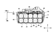
- FIG. 2 is a longitudinal sectional view of the battery pack 1.
- FIG. The internal space formed by the upper case 10 and the lower case 2 accommodates ten cylindrical battery cells 41 .
- Ten battery cells 41 are fixed by separators 42 in a state in which five cells are stacked vertically in two stages.
- the type, size, and number of the battery cells 41 are arbitrary.
- a lithium ion battery cell called 18650 size which has a diameter of 18 mm and a length of 65 mm and can be charged and discharged multiple times, is used.
- five battery cell groups connected in series are connected in parallel to output DC with a rated voltage of 18V.
- Vertically adjacent battery cells 41 are partitioned by flat upper and lower partition walls 43, and front and rear adjacent battery cells 41 are partitioned by flat front and rear partition walls 44 so that they are adjacent to each other.
- the battery cells 41 are held so as not to contact each other.
- a circuit board 45 is fixed on the upper side of the separator 42 .
- the circuit board 45 is a printed circuit board (PCB) on which various electronic elements such as a battery protection IC, a microcomputer, a storage memory, a PTC thermistor, a resistor, a capacitor, a fuse, and a light emitting diode are mounted.
- PCB printed circuit board
- a plurality of metal connection terminals (only the LD terminal 38 is visible here) are fixed to the circuit board 45 to fit with the connection terminals on the electrical equipment main body 201 side.
- a circuit pattern (not shown) is formed on the circuit board 45 to electrically connect the positive electrode side output and the negative electrode side output of the battery cell 41 to the connection terminal group.
- a sensor 61 according to this embodiment is further mounted on the circuit board 45 .
- the sensor 61 is one of the sensors called a triaxial acceleration sensor, and is intended to measure acceleration, and measures three-dimensional inertial motion (translational motion in three orthogonal directions of X, Y, and Z shown in the figure). To detect.
- the sensor 61 corresponds to the "sensor section" of the present invention.
- FIG. 3 is a circuit diagram of the battery pack 1 and the electrical equipment body 201.
- the battery pack 1 is provided with sensing sensors 61 to 69 such as acceleration sensors, and is configured to control the main body of the electric device 201 according to physical information obtained from the sensors.
- the battery pack 1 is electrically connected to the electrical equipment main body 201 via a plurality of connection terminals (32, 34, 36-38, etc.).
- the positive terminal 32 and the negative terminal 37 are power supply terminals connected to the positive and negative terminals of the battery cell 41 , and are connected to the positive input terminal 232 and the negative input terminal 237 of the electrical equipment body 201 .
- the positive side output of the battery cell 41 is connected to the positive terminal 32 and the negative side is connected to the negative terminal 37 .
- the battery pack 1 is further provided with a positive terminal for charging (so-called C+ terminal) as a terminal for electric power, but it is not shown here.
- the battery pack 1 is provided with at least one or more sensing sensors 61 to 69 either built-in or externally.
- the conventional battery pack 1 is provided with a sensor for measuring voltage supplied from the battery cell 41, a sensor for measuring current, and a sensor for measuring temperature.
- the sensors 61 to 69 of this embodiment do not detect internal factors (battery cells 41) of the battery pack 1, but physical, optical, electrical, and magnetic factors originating from the outside of the battery pack 1. are provided to detect any one or more of the following: Examples of the sensors 61 to 69 include an acceleration sensor, a distance sensor (ranging sensor), an optical sensor, a human sensor, a position sensor, a sound sensor, an image sensor, an illuminance sensor, and a magnetic sensor, to which the battery pack 1 is exposed.
- the number of these sensors 61 to 69 to be provided in the battery pack 1 is arbitrary, and one or more may be provided.
- it may be attached outside the case of the battery pack 1 instead of being provided inside the case. In that case, it is preferable to provide a connector for connection at a position accessible from the outside of the battery pack 1 in order to perform electrical wiring between the sensor 62 and the control unit 50 .
- Each of the sensors 61 to 69 is for the purpose of sensing physical information, and is arranged at a position where the purpose can be achieved and which can be housed in the battery pack 1 or can be attached.
- the control unit 50 manages charging and discharging of the battery cell 41 and processes physical information acquired by the sensors 61-69.
- the controller 50 corresponds to the "battery pack side controller" of the present invention.
- the control power supply circuit 51 converts the power of the battery cell 41 into a constant voltage of 3.3 V or 5 V and outputs the constant voltage to the control unit 50 .
- the control unit 50 is mounted on the circuit board 45 (see FIG. 2) and includes a microcomputer, a ROM for storing processing programs and control data, a RAM for temporarily storing data, a timer, and the like. be done. Outputs input from the sensors 61 to 69 are A/D converted by the microcomputer of the control unit 50, and sampling, noise removal processing, and other necessary processing are performed.
- the control unit 50 is further provided with a wireless communication circuit 55 .
- the wireless communication circuit 55 is a circuit for close proximity wireless communication such as Bluetooth (registered trademark).
- the radio communication circuit 55 is provided with an antenna 56 to enable communication within a distance of several tens of meters.
- the microcomputer of the control unit 50 processes the signals input from the sensors 61 to 69 and controls the operation of the main unit of the electrical equipment 201 to which the battery pack 1 is attached.
- the control unit 50 is configured to be able to communicate with the control unit 50 on the electric device main unit 201 side, and has three terminals for communication. is used.
- One is a second signal terminal (T terminal) 34, and this terminal transmits a signal that serves as identification information of the battery pack 1 to the electrical equipment main body 201. It is also used as a communication terminal for transmitting information on the battery pack 1 side via the circuit 53 .
- Another first signal terminal (LS terminal) 36 is a signal terminal for transmitting the output of a thermistor (temperature sensing element) (not shown) provided for measuring the temperature of the battery cell 41. It is also used as a communication terminal for receiving information from the electrical equipment body 201 via the circuit 53 .
- the tool main body communication circuit 53 is a circuit for performing two-way wired communication with the battery communication circuit 260 of the electrical equipment main body 201 using the conventionally used signal terminals of the LS terminal 36 and the T terminal 34 .
- a third signal terminal (LD terminal) 38 is a signal terminal for outputting an abnormal stop signal for protecting the battery cell 41 by the control section 50 via the control signal output circuit 52 .
- the electric device main body 201 is controlled by the control section 250 .
- the controller 250 corresponds to the "apparatus-side controller" of the present invention.
- a control power supply circuit 255 is provided to operate the control unit 250 .
- the control power supply circuit 255 is a power supply for generating a constant low voltage (eg, 3.3 V or 5 V) from direct current supplied to the positive input terminal 232 and the negative input terminal 237 .
- a constant low voltage eg, 3.3 V or 5 V
- the self-holding circuit 259 continuously outputs a signal to the control power supply circuit 255 to keep the control power supply circuit 255 in the ON state.
- the control signal input circuit 261 is a circuit that determines a signal transmitted from the battery pack 1 side via the third signal terminal (LD terminal) 238 and transmits the signal to the control section 250 .
- the battery communication circuit 260 is a circuit for performing two-way communication with the control section 50 of the battery pack 1 using the first signal terminal (LS terminal) 236 and the second signal terminal (T terminal) 234 .
- the control unit 250 includes a microcomputer for outputting drive signals based on processing programs and data, a ROM for storing processing programs and control data, a RAM for temporarily storing data, a timer, and the like.
- the motor 204 is a three-phase brushless DC motor driven by an inverter circuit 252 .
- the motor 204 is of a so-called inner rotor type, and includes a rotor 204a including a plurality of sets (two sets in this embodiment) of permanent magnets (magnets) including N and S poles, and a star. It has a stator 204b consisting of three-phase stator windings U, V, W that are connected.
- the trigger switch 206 When the trigger switch 206 is turned on, the signals from the three Hall elements 265 are detected by the rotational position detection circuit 266, and the controller 250, which receives the detection signals, controls the direction of current flow to the stator windings U, V, and W. and time are calculated, and the motor 204 is controlled to rotate at a predetermined number of revolutions.
- the inverter circuit 252 is composed of six switching elements (Q1 to Q6) such as FETs connected in a three-phase bridge configuration. Each gate of switching elements Q1-Q6 is connected to inverter control circuit 251, and each drain or source of switching elements Q1-Q6 is connected to star-connected stator windings U, V, W. FIG. As described above, the microcomputer included in the control unit 250 changes the DC power input to the inverter circuit 252 into three phases (U phase, V phase and W-phase) supplied to the stator 204b as voltages Vu, Vv, and Vw.
- the PWM signal is supplied to either one of the positive power supply side switching elements Q1 to Q3 or the negative power supply side switching elements Q4 to Q6 of the inverter circuit 252, and the switching elements Q1 to Q3 or the switching elements Q4 to Q6 are switched at high speed. Controls the power supplied to each stator winding U, V, W from DC by In this embodiment, since the PWM signal is supplied to the switching elements Q4 to Q6 on the negative power supply side, the power supplied to each stator winding U, V, W is adjusted by controlling the pulse width of the PWM signal. can be used to control the rotation speed of the motor 204 .
- a current value supplied to the motor 204 is measured by a current detection circuit 256 using a shunt resistor 253 and fed back to the control section 250 .
- the voltage value applied to the inverter circuit 252 is monitored by the controller 250 by measuring the voltage across the capacitor 254 for smoothing by the voltage detection circuit 257 .
- the lighting LED 270 is a light-emitting device that illuminates the area where the tool is to be worked.
- the microcomputer of the control unit 250 detects that the operator has operated a lighting button (not shown) provided on the electrical equipment main body 201, and follows the instruction. The controller 250 turns on or off the lighting LED 270 .
- control unit 250 sets a predetermined lighting mode (blinking, display color change, etc.) in accordance with a communication signal from the microcomputer (control unit 50) of the battery pack 1 so that the electric device main body 201 can be identified by the operator. state.
- the operation mode switch 267 is a switch for setting the tightening strength of the impact tool or the like, the tightening mode, and the like.
- the operation mode set by the operation mode switch 267 is displayed by the corresponding mode display LED 268 which operation mode is selected.
- the transition diagram of FIG. 4 starts when the battery pack 1 is attached to the electrical equipment main body 201 (step 101), the main switch of the electrical equipment main body 201 is turned on, and the microcomputer of the control unit 250 is activated (step 121). ).
- the microcomputer of the control unit 250 is activated when the trigger lever 206a is first pulled to start the operation.
- the control unit 250 on the side of the electrical equipment main body 201 transmits an "information request signal" for requesting transmission of information acquired by the sensors 61 to 69 to the battery pack 1 (steps 122, 102).
- the information to be used does not have to be all sensor information, and the required sensors 61-69 may be selected. Further, not only the "information request signal” but also "equipment body information (equipment information)" for identifying the type of the electrical equipment body 201 is transmitted. This transmission is performed via the first signal terminal 36 and the first signal terminal 236 .
- the "equipment main body information” includes the model name of the electric equipment main body, information on the electric equipment main body necessary for utilizing sensor information, parameters necessary for controlling the electric equipment main body, and the like. If the main body of the electrical equipment to which the battery pack 1 is attached is an old model in which the information from the sensors 61 to 69 cannot be used from the battery pack 1, the information request signal cannot be sent to the battery pack 1 side. Therefore, the subsequent steps are skipped, and without using the sensor information from the battery pack 1, the main body of the electrical equipment operates in the same manner as the conventional one.
- the control unit 50 of the battery pack 1 When the control unit 50 of the battery pack 1 receives the "information request signal" and the "device body information", the control unit 50 of the battery pack 1 controls the electrical device body 201 based on the "device body information”.
- a “reference value” is set (step 111).
- the reference value is a value indicating the correct posture of the main body during work determined for each model.
- the reference value is used as a comparison value when detecting an abnormal posture in a machine such as a circular saw whose main body posture during work is determined depending on the model.
- the work start posture is used as the reference value. set.
- the operator When the operator wants to use the current state as a reference in detecting the inclination of the electric device main body 201, the operator performs a reference value offset operation from the main body side of the electric device 201 (step 123).
- the reference value offset operation the operator determines the posture of the main body of the electric device 201 to position the main body of the electric device 201 at the reference position, and operates a specific button provided on the main body of the electric device 201. (press). This is because it is not possible to determine which position to use as a reference unless there is an instruction from the operator, such as button operation, on the main body side of the electrical device 201 .
- a dedicated or dual-purpose lamp is lit to indicate that the offset operation has been performed. Good luck. In this way, the orientation of the electrical equipment main body can be reset by designating the offset operation button each time a drilling operation is performed, for example, by an electric drill.
- Control unit 250 of electrical equipment main body 201 that has detected the button operation for setting the reference value transmits an "offset instruction signal" to battery pack 1 (step 124). This transmission is performed via the first signal terminal 36 and the first signal terminal 236 (step 103). It should be noted that the offset operation of the reference value of the electrical equipment main body 201 may not be necessary in some cases. In that case, the operator does not operate a specific button, so steps 124 and 103 are skipped.
- the control unit 50 of the battery pack 1 that has received the "offset instruction signal" collects various physical information from the outputs of the sensors 61 to 69 (step 113), and the physical information values obtained at that time are Subsequent detection of physical information using the sensors 61 to 69 is performed as a reference value (step 114).
- This reference value is stored in a storage device (not shown) included in the control unit 50 of the battery pack 1 and maintained until the next reference value is updated.
- the operator starts the operation of the electrical device main body 201 .
- the motor 204 is rotated by operating the trigger lever 206a while pressing the saw blade or tip tool against the mating material.
- the controller 50 of the battery pack 1 collects physical information about the main body of the electrical device 201 and the surroundings of the battery pack 1 (step 115). Examples of information collected here include position information of the battery pack 1 , attitude information of the battery pack 1 , and acceleration information of the battery pack 1 .
- This “physical information” is detected not due to the battery pack 1 (based on internal factors), but due to external factors such as the operation of the electrical device main body 201 .
- the information is also the information for the electrical equipment main body 201 to which the battery pack 1 is attached.
- the detected physical information of the battery pack 1 is stored in a storage device (not shown) included in the controller 50 of the battery pack 1 (step 116). The reason why the physical information is stored is that, since the sensor value always fluctuates, the information immediately before the determination is temporarily stored when performing the determination, and the determination is performed after processing as necessary.
- the control unit 50 of the battery pack 1 calculates the state and operating conditions of the electric device main body 201 according to the detected physical information, the device main body information of the electric device main body 201, and the set reference value setting (step 117). ). This state and operating conditions will be described later with reference to FIGS. 6 to 11.
- FIG. The calculated operating conditions of the electrical equipment body 201 are sent to the control unit 250 of the electrical equipment body 201 via the second signal terminals 34 and 234 (step 104).
- the control section 250 of the electrical equipment main body 201 that has received the "operating condition" controls the output of the load section according to the operating condition (steps 125, 126).
- the control unit 250 of the electric device main body 201 acquires information (operating conditions) determined from sensor information detected by the battery pack 1, and performs control according to the information. After that, steps 112 to 117 and steps 123 to 126 are repeated to repeat a plurality of operations. After that, the main power supply (main switch) of the electrical equipment main body 201 is turned off, or in the case of an electrical equipment main body without a main power supply (main switch), the battery pack 1 is removed from the main body of the electrical equipment main body 201. Then (step 105), the operation of the control unit 250 of the electrical equipment body 201 is stopped (step 127).
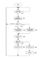
- control of the flow chart of FIG. 5 is software-controlled by the microcomputer included in the control unit 50 executing a computer program.
- the control unit 50 determines whether or not the battery pack 1 is attached to the electrical equipment main body 201, that is, the tool (the electrical equipment main body 201) such as a circular saw (step 131). If it is not installed in step 131 , it waits until it is installed. (Step 132).
- the control unit 50 of the battery pack 1 transmits the output signal of the requested sensor, which is an existing sensor among the sensors 61 to 69, to the electric device main body 201 side.
- the controller 50 of the battery pack 1 uses the received device body information to determine the model of the attached electrical device body 201 (step 133).
- the electrical equipment main body 201 is the first circular saw (circular saw A)
- the threshold for determining the posture of the electrical equipment main body using the sensor value is set to a predetermined value A (step 134)
- Data from the sensors 61 to 69 are acquired after the work is started (step 136).
- step 136 it is not necessary to obtain the outputs of all the sensors 61-69 that are set, and it is sufficient to use only the outputs from the sensors required for the desired control.
- step 133 if the electrical equipment main body 201 is the second circular saw (circular saw B), the threshold for determining the posture of the electrical equipment main body using the sensor value is set to a predetermined value B. (Step 135), the data of the sensors 61 to 69 are acquired after the start of work (Step 136).
- the controller 50 of the battery pack 1 uses the acquired sensor information to determine whether or not the posture of the electrical equipment main body 201 is normal (step 137). For example, in the case of the circular saw A or B, it is determined using the output of the acceleration sensor whether or not the posture is within an appropriate range for working. An example of this determination will be described later with reference to FIGS. 6 to 8.
- FIG. Here, if the posture of the circular saw A or B is normal, an output permission signal is sent to the electrical equipment main body 201 (the circular saw A or B) (step 139), and if the posture is not normal, An output stop signal is transmitted to the electrical equipment body 201 (circular saw A or B) (step 138).
- the output enable signal and the output stop signal can be sent by any signal, but the signal from the LD terminal conventionally provided in the battery pack 1, that is, the LD signal for stopping the operation of the electrical equipment main body 201 in the event of overdischarging. can be used. If the output permission signal has been transmitted (step 139), the user can perform work using the electrical device body 201 (step 140).
- step 133 if the electric device main body 201 to which the battery pack 1 is attached is neither the circular saw A nor the circular saw B, the process returns to step 131 assuming that it is another device main body (tool main body).
- the process returns to step 131 assuming that it is another device main body (tool main body).
- the sent device main body information is used.
- the type of sensor information to be used and its threshold value may be set, and the control when the output value of the sensor reaches the threshold value may be individually set for each connected electric device main body 201 .
- sensor information required for each electrical equipment main body 201 is stored in a table format in a storage device (not shown) included in the control unit 50 of the battery pack 1, and is stored in steps 132 and 133. Can be configured to branch by reference. In this manner, if the reference information for each model of the electrical equipment main body 210 is stored in advance in the storage device of the control unit 50 of the battery pack 1, information from the many sensors 61 to 69 provided in the battery pack 1 can be used to It is possible to control various electrical equipment main bodies 201 .
- the control unit 50 of the battery pack 1 continues to monitor the sensor information and When the trigger switch 206 (trigger lever 206a) is pulled at a certain time, the electric device main body (tool main body) operates. 206a) can be controlled so that it does not operate even if it is pulled.
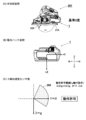
- FIG. 6A and 6B show a case where the posture of the main body of the electric device 210 is horizontal, (A) is a left side view of the circular saw (the electric device 201), and (B) is the state of (A). This is the attitude of the battery pack 1 when .
- the directions of the Y-axis and Z-axis indicated by (B) are the directions based on the battery pack 1, and indicate the directions of the acceleration sensor mounted on the battery pack.
- the battery pack 1 Since the battery pack 1 is horizontally attached to the electric device main body 201, when the electric device main body 201 is in the horizontal state as shown in (A), the battery pack 1 is also in the horizontal state.
- the circular saw has a base 210 for sliding on a material to be cut, and is configured so that the amount of protrusion of the saw blade 205 from below the base 210 (so-called depth of cut) can be changed. . That is, it is configured such that the angle of the circular saw body with respect to the base 210 can be changed.
- FIG. 6A shows a state in which the saw blade 205 protrudes from the base 210 by the maximum amount.
- the circular saw body is in a state within the permitted operation range 280 (example of identification information) in FIG. 6(C).
- the mounting direction of the battery pack 1 with respect to the circular saw body is the front-rear direction (Y-axis direction).
- the information on the electrical device main body 201 includes the mounting direction of the battery pack 1 .
- This type of circular saw corresponds to circular saw A in FIG.
- the reference 0 degrees in FIG. 6(A) corresponds to the threshold value A in step 134 in FIG.
- the permitted operation range 280 and the threshold values A and B are examples of identification information.
- the unit 50 permits the operation of the electrical equipment body 201, that is, executes the procedure of step 139 in FIG.
- whether or not it is "within the operation permitted range 280" can be determined by the Y component and the Z component in the output of the acceleration sensor 61, and -0.87g ⁇ Y ⁇ 0.5g and Z>0. Determine in some cases.
- the dotted line on the horizontal axis is the absolute Y-axis direction (one direction passing through the horizontal plane), and the dotted line on the vertical axis is the absolute Z-axis direction (one direction passing through the extension plane).
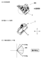
- FIG. 7 shows a state in which the front side of the main body of the electric device 210 is oriented upward by about 45 degrees, (A) is a left side view of the circular saw (the electric device main body 201), and (B) ) is the attitude of the battery pack 1 in the state of (A).
- the battery pack 1 in this posture is in the same posture as shown in (B) together with the electric device main body 201. Therefore, the acceleration sensor 61 is affected by the gravitational acceleration. is 0.64 g in the Z-axis direction and 0.64 g in the Y-axis direction as shown in (C). Since this is outside the range of the aforementioned determination conditions, the control unit 50 of the battery pack 1 determines that the operation of the electrical equipment body 201 should be prohibited (corresponding to step 137 in FIG. 5), and 201 (see step 138 in FIG. 5).
- FIG. 8 shows a state in which the posture of the main body of the electrical device 210 is reversed and rotated about 150 degrees from the state of (A).
- This state corresponds to a working state in which an operator uses an electric circular saw to cut tree branches or cut a ceiling tree from below.
- FIG. 8A is a left side view of the circular saw (electric device main body 201), and
- FIG. 8B is the posture of the battery pack 1 in the state of (A).
- the battery pack 1 in the posture shown in FIG. 8A is affected by gravitational acceleration, and the detection value of the acceleration sensor 61 in the Z-axis direction is ⁇ 0.87 g and in the Y-axis direction is 0.5 g.
- the detected value in the Z-axis direction is a negative value because the sensor 61 is upside down. Since this is outside the range of the aforementioned determination conditions, the control unit 50 of the battery pack 1 determines that the operation of the electrical equipment body 201 should be prohibited (corresponding to step 137 in FIG. 5), and 201 (see step 138 in FIG. 5).
- the controller 50 of the battery pack 1 determines the posture of the circular saw, and stops the operation of the electrical device main body 201 when the electrical device main body 201 falls into an inappropriate posture. I explained the control to let With this control, it is possible to effectively prohibit the work of operating the circular saw in an inappropriate posture using the battery pack 1 with the sensor.
- the detection results in the X-axis direction are not referred to for the sake of simplification of the description, but the detection results of all the three axes of the acceleration sensor 61, the X-axis, the Y-axis, and the Z-axis. You may perform advanced control by further attitude determination with reference to .
- the output of any one of the other sensors 62 to 69 may also be used to control the operation of the electrical equipment main body 201.
- the main body of the electric device 201 in FIG. 9 is the same as the electric device main body 201 shown in FIGS. 1 and 6 to 8, and (A) is a left side view and (B) is a front view.
- the attached battery pack 1A is different from the battery pack 1 of FIG. 2 in that a distance sensor 63 is added to the bottom surface of the lower case 2 .
- the distance sensor 63 measures whether an object exists below the bottom surface of the lower case 2 based on the distance to the object.
- the distance sensor 63 can detect the set angle of the base 210 by measuring the distance to the base 210 and detect the depth of cut and the angle of inclination of the saw blade 205 .
- the distance sensor 63 corresponds to the "sensor section" of the present invention.
- the sensor information acquired by the control unit 50 is transmitted to the control unit 250 of the electrical equipment body 201 via the second signal terminals 34 and 234 .
- This sensor information is physical information that changes with the attitude of the electrical device main body 201 (changes due to “external factors” when viewed from the battery pack 1 ).
- the microcomputer of the control unit 250 grasps the distance between the sensor mounting position and the main body of the electrical device 201 (here, the distance to the base 210), and performs control according to the depth of cut and the angle of inclination.
- Optimize As an example of control optimization, when the depth of cut is shallow or the slope is not applied, light load work is assumed. Since heavy load work is assumed when the motor is being applied, the motor rotation speed may be decreased to increase the torque.
- the electrical equipment main body 201 is provided with a segment display device or a dot matrix display device (for example, a liquid crystal display), the depth of cut and the angle of inclination may be digitally displayed there. .
- FIG. 9A shows the state when the rear end side of the base 210 is closest to the main housing 202 (battery pack 1) (position where the cutting depth is maximum).
- the distance from sensor 63 to base 210 is S1 .
- FIG. 10A shows a case where the base 210 is fixed so that the rear end of the base 210 is separated from the main body (main housing 202). In this case, the distance from the distance sensor 63 to the base 210 is S2 . ) is set shallow.
- FIG. 11A is a side view of a battery pack 1B and an electrical equipment main body 301 according to the third embodiment of the present invention, showing a state at the start of drilling work.
- This electrical equipment main body 301 is shown as an example of a driver drill.
- a brushless DC motor (not visible in the figure) is housed inside a housing 302, and power transmission parts (not visible in the figure) such as a speed reduction mechanism for reducing the rotation force of the motor and a clutch mechanism. not) to rotate the tip tool 310 .
- the tip tool 310 shown in FIG. 11 is a drill bit.
- a chuck (tip tool holder) 308 is provided at the tip of the output shaft (not visible in the figure) to hold the tip tool 310 .
- a handle portion 303 is formed so as to be connected to the portion of the housing 302 that accommodates the motor, and the battery pack 1B is attached to the distant end of the handle portion 303 (the end on the side opposite to the motor).
- a trigger lever 306 is provided on a portion of the handle portion 303 .
- a normal/reverse switching lever 307 for switching the rotation direction of the motor is provided near the trigger lever 306 . The user grips the handle portion 303 with one hand, presses the distal end portion 310a of the tip tool 310 against the mating member 330 so as to be positioned, and pulls the trigger lever 306 with the index finger or the like to adjust the trigger depression amount (operation amount). adjust and control the speed of a motor (not shown).
- the configuration of battery pack 1B is the same as that of battery pack 1 of the first embodiment, except for the types of sensors 61 to 69 (see FIG. 3) mounted.
- a distance sensor 64 (64a, 64b) is provided on the housing of the battery pack 1B.
- the distance sensor 64 uses light (laser) to measure the distance to a distant object without contact, and includes a light-emitting portion 64a and a light-receiving portion 64b.
- the distance sensor 64 corresponds to the "sensor section" of the present invention. In this embodiment, the distance from the electric device main body 301 to the counterpart material (punched material) 330 is not measured, but the distance from the battery pack 1B to the counterpart material (punched material) 330 is measured.
- This distance is physical information that changes with the attitude of the electrical device main body 301 (changes due to “external factors” when viewed from the battery pack 1 ).
- the light emitted from the light emitting portion 64a of the battery pack 1B is reflected by the mating member 330 such as wood and returns to the battery pack 1 side, and is received by the light receiving portion 64b.
- the control unit 50 of the battery pack 1B analyzes and calculates the reflected light, calculates the distance D1 from the light emitting unit 64a to the mating member 330, and outputs the distance D1 to the control unit 250 of the electrical device main body 301.
- the distance sensor 64 By using the distance sensor 64 in this manner, the drilling depth S3 can be detected and the drilling can be automatically stopped at an arbitrary depth.
- the drilling depth S3 is set and stored in the microcomputer of the control unit 50 on the battery pack 1 side before each drilling operation, but the setting method is arbitrary.
- the controller 50 on the battery pack 1B side measures the distance D2 to the mating member and stores the distance D2 in the temporary storage device.
- the control unit 50 continuously monitors the distance to the counterpart material during the drilling operation, and when the distance D 2 becomes the distance D 1 - drilling depth S 3 , electricity is applied via the third signal terminals 38 and 238.
- a stop signal is transmitted to the controller 250 on the device main body 301 side.
- FIG. 12A and 12B are diagrams showing the battery pack 1B shown in FIG. 11, where (A) is a left side view and (B) is a rear view.
- the battery pack 1B has a configuration in which a distance sensor 64 (a light emitting portion 64a, a light receiving portion 64b, and a distance measuring portion (not shown)) is provided as one of the sensors 61-69.
- the distance sensor 64 is provided in the lower case 2 near the center in the left and right direction.
- the battery pack 1B As described above, by changing a conventional battery pack without a sensor to the battery pack 1B according to the present embodiment, it is possible to drill holes in the mating member 330 to an accurate depth.
- the above example illustrates a drilling operation, it can be similarly applied when the tip tool 310 is a driver bit. That is, when the screw is tightened, the motor is automatically stopped when the position of the screw head matches the surface of the mating member 330 according to the length of the screw. can be tightened to
- a distance sensor using light has been described, but other forms of distance sensors, such as a distance sensor using ultrasonic waves, or other distance sensors can be similarly applied. can.
- FIGS. 13A and 13B are diagrams showing a battery pack 1C according to a fourth embodiment of the present invention, where (A) is a left side view and (B) is a rear view.
- a human sensor 65 is provided as one of the sensors 61-69.
- the human sensor 65 is used to move the electrical equipment main body 301 and the like by detecting ambient temperature changes using an infrared sensor.
- the human sensor 65 corresponds to the "sensor section" of the present invention.
- the human sensor 65 is provided on the left side of the display section 80 of the upper case. By providing the human sensor 65 at this position, it is possible to detect whether or not the operator has gripped the handle portion 303 of the electrical equipment main body 301 .
- the value detected by the human sensor 65 is physical information that changes not due to the battery pack 1 but due to an external factor such as the operator.
- the control unit 50 of the battery pack 1C can control to activate the control unit 250 on the electric device main body 301 side.
- This distance is physical information that changes with the attitude of the electrical device main body 301 (changes due to “external factors” when viewed from the battery pack 1 ).
- an activation circuit is provided on the electrical equipment main body 301 side to activate the control unit 250 when a start instruction signal is transmitted to the electrical equipment main body 301 side via the second signal terminals 34 and 234. It is necessary to set it in
- a sensor other than the human sensor in or near the inner area of the display section 80 of the battery pack 1C.
- a fingerprint sensor may be provided as a sensor unit instead of or in addition to the human sensor 65 so that the operator can detect the fingerprint sensor (see FIG. 1) of the battery pack 1C before starting work. (not shown) is touched to perform fingerprint authentication, the control unit 50 of the battery pack 1C can control to activate the control unit 250 on the electric device main body 301 side.
- FIG. 14 illustrates an electrical equipment body 401 according to a fifth embodiment of the invention.
- 14A and 14B are vertical cross-sectional views of an electric device main body 401 controlled using a battery pack 1 having sensors 61 to 69, (A) showing a state in which the hammer is in the initial position (forward position), and (B). indicates a state in which the hammer collides with the cam end and causes vibrations throughout the equipment that are different from those during normal striking operations.
- illustration of the battery pack 1 is omitted here, the battery pack 1 with the same acceleration sensor 61 as in the first embodiment is used.
- the acceleration sensor 61 corresponds to the "sensor section" of the present invention.
- the hammer 440 is always biased forward by a hammer spring (not shown), and is positioned forward by a cam mechanism using a cam ball (not shown) and a cam groove 452 when stationary. At this position, the striking claw of the hammer 440 overlaps the struck claw of the anvil 460 in the direction of the axis A1.
- the spindle 430 is rotationally driven, the rotation is transmitted to the hammer 440 via the cam mechanism, and the striking pawl of the hammer 440 engages the pawl to be struck of the anvil 460 .
- the hammer 440 and the anvil 460 rotate synchronously (continuous rotation) for the time being from the start of fastening of the electrical equipment main body 401 .
- the hammer 440 compresses the hammer spring (not shown) toward the rear. (Motor 404 side) gradually retreats. Normally, the rear end of the hammer 440 does not reach the stopper position due to this retraction. may collide with stopper 456 .
- the acceleration sensor 61 mounted on the battery pack 1 detects a large acceleration in the horizontal direction (X direction, Y direction). This acceleration is not generated by an internal factor of the battery pack 1, but is physical information generated by an external factor caused by the operation of the outside of the battery pack 1 (electrical device main body 401).
- the control unit 50 of the battery pack 1 acquires the acceleration detected by the acceleration sensor 61, and immediately stops the motor 404 of the electric device main body 401 when a large vibration exceeding the threshold value is detected, or stops the motor 404. The work continues until the trigger lever 406 is released while the output is greatly reduced.
- the abnormal vibration is detected by the acceleration sensor 61 on the battery pack 1 side, and the control unit 50 on the battery pack 1 side determines whether or not it is necessary to change the control of the electrical equipment main body 401 based on the detection result.
- the determination result is transmitted to the control section 250 of the electrical equipment main body 401 via the third signal terminals 38 and 238 .
- the control unit 250 of the electric device main body 401 receives the communication information and performs necessary control, for example, immediately stopping the motor 404 or reducing the output of the motor 404 by a certain amount (eg, 40%).
- the output of the acceleration sensor 61 on the battery pack 1 side is used to control the output of the motor in a device such as an impact tool or a hammer drill that is likely to vibrate. It is possible to perform control to lower the
- a position sensor is provided as a sensor unit provided in the battery pack, and by specifying the position (place) of the battery pack, the position of the electrical equipment connected thereto is detected.
- a position sensor a GPS (Global Positioning System) sensor is provided on the circuit board 45 (see FIG. 2) of the battery pack 1E (not shown). This GPS sensor performs three-dimensional positioning of a radio wave receiving device on the earth based on the arrival times of radio waves of time signals emitted from a plurality of satellites.
- the control unit (microcomputer) of the battery pack 1E determines whether or not the battery pack 1E is attached to the electrical equipment main body, and determines whether or not the battery pack 1E is attached to the electrical equipment main body When the battery pack 1E is attached to the device main body and the microcomputer of the electrical device main body is activated, the battery pack 1E can detect its position information.
- the position of the electrical equipment main body to which the battery pack 1E (not shown) is attached can be detected, it becomes possible to set the allowable operating range (area) of the electrical equipment main body. For example, by registering the location information of the planned work site, the operation of the electrical equipment main body is permitted within the planned work site, and if the microcomputer of the battery pack 1E determines that the work site is not the scheduled work site, the electrical equipment It may be controlled to stop the operation of the main body (for example, stop the motor). For this control, information about the permitted work range is registered in advance in the storage device of the electrical equipment main body. When the battery pack 1E is attached to the electrical equipment main body, the microcomputer of the battery pack 1E obtains information on the permitted work range from the microcomputer of the electrical equipment main body, and controls using the information.
- a control unit (microcomputer) of an electric device main body detects the position (place) when the battery pack 1E is attached to the electric device main body and the microcomputer of the electric device main body is activated. By storing it in the storage device, it becomes possible to record the work location of the electrical equipment main body along with the time.
- a "sound sensor” is provided as a sensor unit provided in the battery pack 1F (not shown) to detect sounds coming from outside the battery pack (physical information due to external factors). controls the operation of the electrical equipment connected to the battery pack.
- the sound sensor is one of the sensors (first sensor) for collecting sounds (sound waves) coming from the outside of the battery pack 1, and detects, for example, the magnitude of compressional waves propagating in air (medium). do.
- the sound sensor it is preferable to use an electrodynamic, electrostatic, or piezoelectric microphone in one to four directions viewed from the horizontal plane of the battery pack.
- control unit (microcomputer) of the battery pack 1F monitors the output of the sound sensor and stops the motor when the surrounding sound (noise) becomes louder during operation or standby of the electric device. It is possible to control Furthermore, the microcomputer in the battery pack 1F detects the sound (operation sound) emitted from the main body of the electrical equipment by monitoring the output of the sound sensor, determines whether the bolt is tightened, and controls the motor to stop. It is possible.
- an "image sensor for example, a camera)
- the battery pack uses the image information to help control the main body of the electrical equipment.
- the control unit (microcomputer) of the battery pack acquires the image information of the surrounding area and uses known image recognition technology to identify the work target area such as a circular saw. ) can be controlled to stop the motor of the main body of the electrical equipment when a person enters.
- an "illuminance sensor” is provided as a sensor unit provided in a battery pack 1H (not shown) to provide information on the brightness of the outside of the battery pack (for example, illuminance, which is a physical sensor due to external factors).
- the battery pack can use the illuminance image information to help control the main body of the electrical equipment.
- the surrounding brightness is monitored, and depending on the brightness of the site, the brightness of the main body of the electric equipment such as a light, the brightness of the display device of the main body of the electric equipment (for example, You can adjust the brightness of the LCD backlight.
- the settings such as the number of revolutions of the electrical equipment main body may be controlled to change when the illuminance sensor portion provided in the battery pack 1H (not shown) is covered with a hand.
- Embodiment 10 is a control method for an electrical device main body 501 having a shape that is detachable by sliding the battery pack 1 in the vertical direction (in the direction of the Y axis and in the vertical direction) with respect to the electrical device main body 501. Description will be made with reference to FIGS. 15 to 17.
- FIG. An example of a circular saw body is shown as an electric device main body 501.
- the electric device main body 501 corresponds to the electric device main body 201 shown in FIG.
- the configuration is the same as that of the electrical equipment main body 201 .
- the main body (circular saw main body) of the electric device 501 shown in FIG. 15 is horizontal, and the angle formed by the base 510 with respect to the horizontal plane is 0 degrees.
- FIG. 15A is a left side view of the circular saw (electrical device 501)
- FIG. 15B is the posture of the battery pack 1 when the electrical device 501 is in the state of (A) (reference 0 degree).
- the battery pack 1 can be attached to the battery pack attachment portion 502a by moving it relative to the electrical device main body 501 from top to bottom. For example, when the battery pack 1 is positioned horizontally in the electrical equipment main body 501 and is in a state as shown in (A), the Y-axis direction of the battery pack 1 is in a vertical state.
- the electrical equipment main body 501 includes a base 510 placed on and sliding on the object to be cut, a saw blade 505 protruding from an opening provided in the base 510 to the bottom surface of the base, a motor 504 for rotating the saw blade, and a motor 504 .
- the handle portion 503 has a handle portion 503 provided on the top of the housing that accommodates the .
- the handle portion 503 is provided with a trigger lever 506 for turning on the rotation of the motor 504 .
- the configuration of the electrical equipment main body 501 is the same as that of the electrical equipment main body 201 shown in FIG.
- the control unit 50 of the battery pack 1 permits the operation of the electric device main body 501, that is, executes the procedure of step 139 in FIG.
- whether or not it is within the "permissible operation range 580" can be determined by the Y component and the Z component in the output of the acceleration sensor 61 provided in the battery pack 1, and -0.87g ⁇ Z ⁇ 0.5g and Y ⁇ 0, it is determined to be "operable”.
- the state of FIG. 15 (reference 0 degrees) corresponds to the threshold value B of step 134 of FIG.
- the dotted line on the horizontal axis is the absolute Z-axis direction (one direction passing through the horizontal plane), and the dotted line on the vertical axis is the absolute Y-axis direction (one direction passing through the extension plane).
- FIG. 16 shows a state in which the front side of the main body of the electric device 501 is turned upward by about 45 degrees from the state shown in FIG. 15(A). It is a left side view, and (B) is a posture of the battery pack 1 in the state of (A). 15, the battery pack 1 in this posture assumes the posture shown in FIG.
- the detected values in the Y-axis direction and the Z-axis direction are ⁇ 0.64 g in the Y-axis direction and 0.64 g in the Z-axis direction, as shown in (C). Since this falls outside the above-described determination condition, that is, the operation permission range 580, the control unit 50 of the battery pack 1 determines that the operation of the electric device body 501 should be prohibited (step 137 in FIG. 5). ), and sends an output stop signal to the electrical equipment main body 501 (see step 138 in FIG. 5).
- FIG. 17 shows a state in which the posture of the main body of the electrical device 501 is reversed and rotated about 150 degrees from the state shown in FIG. 15(A).
- This state corresponds to a working state in which an operator uses a circular saw (electric device main body 501) to cut branches of a tree or cut a ceiling tree from below.
- FIG. 17A is a left side view of the circular saw (electric device main body 501)
- FIG. 17B is the posture of the battery pack 1 in the state of (A).
- the battery pack 1 in the posture shown in FIG. 17A is affected by gravitational acceleration, and the detection value of the acceleration sensor 61 in the Y-axis direction is 0.87 g, and the detection value in the Z-axis direction is 0.5 g. .
- the detected value in the Y-axis direction is a positive value because the sensor 61 is upside down. Since this falls outside the above-described determination condition, that is, the operation permission range of the operation permission range 580, the control unit 50 of the battery pack 1 determines that the operation of the electric device main body 501 should be prohibited (see FIG. 5). (corresponding to step 137), and an output stop signal is sent to the electrical equipment main body 501 (see step 138 in FIG. 5).
- Circular saw B (electrical equipment main body 501) having a configuration in which the battery pack 1 is vertically attached to and detached from the circular saw main body is similar to circular saw A (electrical equipment main body 201) in FIGS.
- the controller 50 of the battery pack 1 can set a threshold value (simplified motion permission) based on the direction in which the battery pack 1 is mounted, determine the posture, and determine whether or not the motion is possible. Therefore, it is possible to effectively prohibit the operation of operating the circular saw B (electrical device main body 501) in an inappropriate posture using the sensor-equipped battery pack 1 .
- the battery pack 1 is attached to and detached from the circular saw body in the front-rear direction (horizontal direction), and in FIGS.
- the direction in which the battery pack 1 is attached to the circular saw body (electrical device main body 201, 501) can be set arbitrarily.
- the attachment/detachment directions of the plurality of battery packs 1 may be the same, or the attachment/detachment directions of the plurality of battery packs 1 may be different.
- the controller 50 of the battery pack 1 can determine the attitude based on the device main body information and the sensor information of the electrical device main bodies 201 and 501 .
- the electric device main bodies 201 and 501 transmit their own device main body information including the attachment/detachment direction and the number of the battery packs 1 to the control unit 50 of the battery pack 1 .
- the control unit 50 determines the attitude of the electrical equipment main bodies 201 and 501 based on the attitude information detected by the sensor and the information on the attachment/detachment direction of the battery pack 1, and controls the electrical equipment main bodies 201 and 501 according to the determination result. good.
- FIG. 18 shows a circuit diagram of a battery pack and an electric device main body 201A in a configuration in which a plurality of battery packs 1 can be connected to the electric device main body 501 at the same time.
- the main housing 202 of the electrical equipment body (for example, circular saw C) 201A is provided with a plurality of (here, two) battery pack mounting portions, and the positive input terminal 232, the negative input terminal 237, the first to the first A plurality of sets of terminals equivalent to the third signal terminals 234, 236, 238 are provided according to the number of attachable battery packs 1 (here, two).
- FIG. 18 shows only one set of the positive input terminal 232 and the negative input terminal 237, this means that a plurality of battery packs are connected in parallel with each other. are provided in multiple sets (two sets). Battery communication circuits 260a and 260b corresponding to each battery pack 1 are also provided. Although there is only one control signal input circuit 261, control signals from a plurality of battery packs 1 are input.
- the second battery pack (2) has the same configuration as the first battery pack (1). A number sign is attached.
- the two battery packs (1) and (2) perform mutual wireless communication, one battery pack (1) collects information on the other battery pack (2), and one battery pack (1) ) may be configured to communicate with the electrical equipment main body 201A as a representative. In this case, it is not necessary to provide two battery communication circuits such as 260a and 260b, but only one.
- FIG. 19 is a flow chart showing the control procedure of the battery pack 1 when the electric device main body 201A (circular saw C) shown in FIG. 18 is added to the judgment element in step 133 of the flow chart of FIG.
- the control from steps 131 to 140 is the same as the procedure shown in FIG.
- the controller 50 of the battery pack 1 determines the model of the attached electrical device main body 201 using the received device main body information.
- the electric equipment body 201 is the first circular saw (circular saw A) and the second circular saw (circular saw B)
- the process is the same as in FIG. move on.
- the electric device main body 201A is the third circular saw (circular saw C) to which a plurality of battery packs can be attached at the same time, the process proceeds to step 141 .
- the control unit 50 of the battery pack 1 connected to the electrical device main body 201 refers to the information on the battery pack mounting portion among the main body information acquired at step 132 .
- the battery pack 1 is connected to one of the battery pack mounting portions (for example, two) of the battery pack mounting portions (the first)
- the information including the mounting direction of the first battery pack mounting portion Based on this, the threshold for determining the posture of the electrical equipment main body 201A is set to a predetermined value C (step 142).
- the threshold value for posture determination of the electric device main body 201A is set to a predetermined value D based on information including the mounting direction of the battery pack mounting portion No. 2. (step 143).
- the control unit 50 of the battery pack 1 determines the posture of the electrical equipment main body 201A based on the predetermined value C or D, and outputs a control signal to the electrical equipment main body (steps 136 to 139).
- the controllers 50 of all battery packs 1 connected to the electrical equipment body 201A execute these processes. Further, when a plurality of battery packs 1 are connected, the posture of the electrical equipment main body 201A is determined based on the information of one of the battery packs 1, and one of the battery packs 1 sends a control signal to the electrical equipment main body 201A. may be output. Further, in step 126 of FIG. 4, if the operating conditions received from the plurality of battery packs 1 do not match, for example, if one of the battery packs 1 is out of the operating permission range, the control unit 250 of the electrical equipment body 201A Driving may be prohibited (stopped).
- the electric device main body 201A to which a plurality of battery packs 1 can be connected at the same time it can be driven if at least one battery pack 1 is connected (in the case of a configuration in which a plurality of battery packs 1 are connected in parallel), or when a plurality of battery packs 1 are connected in parallel. It is conceivable that the device cannot be driven unless all battery packs 1 are connected (in the case of a configuration in which a plurality of battery packs 1 are connected in series).
- the control unit 250 of the electrical equipment main body 201A is configured to determine whether or not the required number of battery packs 1 are connected based on the information from the battery packs 1 received via the battery communication circuits 260a and 260b. ing.
- the data may be transmitted and received between each battery pack 1 and the electrical device main body 201A.
- the control unit 50 of the normal battery pack 1 transmits a signal indicating abnormality to the electrical equipment main body 201A.
- the control unit 50 of the battery pack 1 having abnormal data may transmit a signal indicating the abnormality to the electrical equipment body 201A.
- the control section on the side of the electrical equipment main body 201A may determine a data abnormality and prohibit (stop) the driving of the electrical equipment main body 201A.
- the present invention is not limited to the above-described embodiments, and various modifications can be made without departing from the scope of the invention.
- various sensors are provided on the battery pack side, and the sensor output is processed by a control unit (microcomputer) on the battery pack side, It can be configured to transmit the processed information to the control unit on the side of the main body of the electrical equipment attached by priority or wireless communication, and to control the operation of the main body of the electrical equipment.
- the types of sensors are not limited to the above examples.
- the control according to the physical information may include stopping or decelerating the motor, changing the output, and notifying with a buzzer, LED, or the like.
- Trigger lever 307... Normal/reverse switching lever, 310... Tip Tool 310a Tip Part 330 Mating Material 401 Electric Device Body 404 Motor 406 Trigger Lever 430 Spindle 440 Hammer 452 Cam Groove 456 Stopper 460 Anvil 501 Electrical device (main body) 502a Battery pack mounting part 503 Handle part 504 Motor 505 Saw blade 506 Trigger switch 510 Base A1 Rotation axis of motor
Abstract
Provided are a battery pack and an electrical device in which one or more sensors are provided on the battery pack side, and sensor information acquired at the battery side is used to control the body of an electrical device 301. A plurality of sensors 61-69 that collect and output physical information attributable to an external factor are provided to a battery pack 1, and a control unit 50 of the battery pack 1 processes signals detected by the sensors 61-69, and creates a control signal compatible with an attached electrical device body 201. The control unit 50 of the battery pack 1 transmits to the body of the electrical device a signal for controlling the body of the electrical device body via a communication terminal, thereby enabling a control unit 250 of the electrical device body 201 to perform optimal control using the sensor information.
Description
本発明は、本発明は電池パック及び電気機器に関する。
The present invention relates to battery packs and electrical equipment.
電池パックを電源とした携帯型の電気機器が広く普及している。このような周知の技術は、例えば特許文献1に開示されている。特許文献1には、電池パックと電気機器本体との間に装着されるアダプタであって、傾きセンサ、制御部及び信号出力端子を備えたアダプタが開示されている。特許文献1のアダプタは、傾きセンサによって検知された傾きが所定の値より大きいことを検知した場合に、アダプタの制御部が、信号出力端子から電気機器本体に停止信号を出力して、電池パックから電気機器本体への電力供給を遮断するように構成されている。特許文献1に開示されたアダプタは、電池パックと電気機器本体の間に装着されるものであるため、電気機器が全体として大きくなり、アダプタを装着しない場合と比べて作業性に劣るものであった。そこで、センサを電池パックに設けることで電気機器の大型化を抑えた構成が特許文献2に記載されている。
Portable electric devices powered by battery packs are widely used. Such well-known technology is disclosed, for example, in Japanese Unexamined Patent Application Publication No. 2002-200012. Patent Literature 1 discloses an adapter that is mounted between a battery pack and an electric device main body and that includes an inclination sensor, a control section, and a signal output terminal. In the adapter disclosed in Patent Document 1, when the tilt sensor detects that the tilt detected by the tilt sensor is larger than a predetermined value, the controller of the adapter outputs a stop signal from the signal output terminal to the main body of the electric device, and the battery pack is stopped. is configured to cut off the power supply from the main body of the electrical equipment. Since the adapter disclosed in Patent Document 1 is mounted between the battery pack and the main body of the electrical equipment, the electrical equipment as a whole becomes large, and the workability is inferior to the case where the adapter is not attached. rice field. Therefore, Patent Document 2 describes a configuration in which a sensor is provided in a battery pack to suppress an increase in the size of an electrical device.
特許文献2には、電池パックに加速度センサと制御部を設け、電池パック側の制御部によってインパクト工具本体による打撃を検知し、制御部が電池パック側に設けられたスイッチング素子をオフにすることで、電池パックからインパクト工具への電力供給を遮断するよう構成されたインパクト工具が開示されている。
In Patent Document 2, a battery pack is provided with an acceleration sensor and a control section, the control section on the battery pack side detects the impact by the impact tool main body, and the control section turns off the switching element provided on the battery pack side. discloses an impact tool configured to cut power from the battery pack to the impact tool.
特許文献2における制御は、電池パックの判断により電池パックの内部で本体側への電力供給を遮断するものである。よって、大きな打撃力を発生するインパクト工具に接続された場合は打撃を検知できるが、小さな打撃力を発生するインパクト工具に接続された場合は打撃を検知できないといった問題が生じ、汎用性が低いと考えられる。汎用性を高くするために、接続されるインパクト工具等の電気機器本体から出力される機器情報に応じた制御をすることが有用であると考えられる。また、電池パックは様々な電気機器本体に接続されて使用されるため、打撃検知以外の情報を検出できるセンサを設ければ利便性が向上する。
The control in Patent Document 2 cuts off the power supply to the main body inside the battery pack based on the judgment of the battery pack. Therefore, when connected to an impact tool that generates a large impact force, the impact can be detected, but if it is connected to an impact tool that generates a small impact force, the impact cannot be detected. Conceivable. In order to increase versatility, it is considered useful to perform control according to device information output from an electrical device main body such as an impact tool to be connected. In addition, since the battery pack is used by being connected to various electrical equipment main bodies, convenience can be improved by providing a sensor capable of detecting information other than impact detection.
本発明は上記背景に鑑みてなされたもので、その目的は、電気機器の大型化を抑制しつつ、接続される電気機器本体から出力される機器情報に応じた制御を可能にした電池パック及びそれを用いた電気機器を提供することである。
本発明の他の目的は、利便性を向上させた電池パック及びそれを用いた電気機器を提供することである。
本発明の他の目的は、電池パック側にマイコン及び1つ以上のセンサを設け、電池側マイコンと本体側マイコンとの通信を行うことで、電池パックによる電気機器本体側の制御を支援するようにした電池パック及び電気機器を提供することである。 SUMMARY OF THE INVENTION The present invention has been made in view of the above background. It is to provide an electric device using it.
Another object of the present invention is to provide a battery pack with improved convenience and an electric device using the same.
Another object of the present invention is to provide a microcomputer and one or more sensors on the battery pack side and perform communication between the battery side microcomputer and the main body side microcomputer so that the battery pack can support the control of the main body of the electrical equipment. It is to provide a battery pack and electric equipment that are
本願において開示される発明のうち代表的な特徴を説明すれば次のとおりである。
本発明の一つの特徴によれば、電気機器本体に装着可能な電池パックであって、電池パックの外的要因に起因する物理的情報を収集して出力するよう構成されたセンサ部と、センサ部に接続されると共に機器側制御部から出力される機器情報が入力される電池パック側制御部と、機器側制御部を有して構成される。電池パック側制御部は、機器情報及び物理的情報に応じて電気機器本体を制御する。ここで、外的要因に起因する物理的情報は、電池パックの位置、姿勢、又は加速度に関する情報を含む。電池パック側制御部は、機器側制御部と通信可能に構成される。 The typical features of the invention disclosed in the present application are as follows.
According to one feature of the present invention, there is provided a battery pack attachable to an electric device main body, the sensor unit configured to collect and output physical information caused by external factors of the battery pack; and a device-side control unit connected to the unit and receiving device information output from the device-side control unit. The battery pack side control unit controls the electric device main body according to the device information and the physical information. Here, the physical information caused by external factors includes information regarding the position, orientation, or acceleration of the battery pack. The battery pack side controller is configured to be communicable with the device side controller.
本発明の他の特徴によれば、電池パックは、電気機器本体と電気的な接続を可能とする金属製の接続端子を複数有し、接続端子の一部を用いて電気機器本体との通信を行う。電池パック側制御部は、物理的情報に応じて電気機器本体の動作条件を変更可能に構成され、接続された電気機器本体に応じて電気機器本体の動作条件を変更可能に構成される。また、電池パックが装着可能な電池パック装着部と、電池パックによって駆動する負荷部を有する電気機器本体と、電池パックを備えた電気機器が構成される。
According to another feature of the present invention, the battery pack has a plurality of metal connection terminals that enable electrical connection with the electrical equipment main body, and uses part of the connection terminals to communicate with the electrical equipment main body. I do. The battery pack side control unit is configured to be able to change the operating conditions of the electrical device main body according to the physical information, and is configured to be able to change the operating conditions of the electrical device main body according to the connected electrical device main body. Further, the electric equipment includes a battery pack mounting portion to which a battery pack can be attached, an electric equipment main body having a load portion driven by the battery pack, and an electric equipment including the battery pack.
本発明のさらに他の特徴によれば、機器側制御部を有し、電池パックの外的要因に起因する物理的情報を収集して出力するよう構成されたセンサ部と、センサ部に接続されると共に機器側制御部から出力される機器情報が入力される電池パック側制御部と、を有する電池パックが構成される。電池パック側制御部は、(1)機器側制御部がセンサ部を用いた制御を可能とする場合は、センサ部によって検出された出力を用いて電気機器本体を制御する信号を電気機器本体に送信し、(2)機器側制御部がセンサ部を用いた制御が不能な場合は、センサ部による検出を行わないように構成した。
According to still another feature of the present invention, there is provided a device-side control section, a sensor section configured to collect and output physical information caused by external factors of the battery pack, and a sensor section connected to the sensor section. and a battery pack-side control section to which device information output from the device-side control section is input. (1) When the device-side control unit enables control using the sensor unit, the battery pack-side control unit sends a signal for controlling the electrical device main unit using the output detected by the sensor unit to the electrical device main unit. (2) When the device-side control unit cannot perform control using the sensor unit, the sensor unit is configured not to perform detection.
本発明のさらに他の特徴によれば、電池パックは、センサ部から出力された情報が識別情報と一致しない場合には電気機器本体の駆動を禁止する信号を出力する。この識別情報は、電池パックの装着方向を基準にした動作許可範囲を含む。電池パックは、センサ部から出力された情報が動作許可範囲から外れている場合には電気機器本体の駆動を禁止する信号を出力するよう構成される。電池パックは、電池パックの外的要因に起因する物理的情報を収集して出力するよう構成されたセンサ部と、センサ部に接続されると共に機器側制御部から出力される電池パックの装着方向を識別する識別情報が入力される電池パック側制御部と、を有する。電池パック側制御部は、識別情報と物理的情報に基づいて電気機器本体を制御する。
According to still another feature of the present invention, the battery pack outputs a signal for prohibiting driving of the electrical equipment body when the information output from the sensor section does not match the identification information. This identification information includes the permitted operation range based on the mounting direction of the battery pack. The battery pack is configured to output a signal that prohibits driving of the electric device main body when the information output from the sensor section is out of the permitted operation range. The battery pack includes a sensor unit configured to collect and output physical information caused by external factors of the battery pack, and a mounting direction of the battery pack connected to the sensor unit and output from the device-side control unit. and a battery pack side control unit to which identification information for identifying the is input. The battery pack side control section controls the electrical equipment main body based on the identification information and the physical information.
本発明によれば、電気機器の大型化を抑制しつつ、接続される機器本体に応じた最適な制御を可能にした電池パック及び電気機器を提供することができる。また、利便性を向上させた電池パック及びそれを用いた電気機器を提供することができる。さらに、電池パック側制御部は、センサによって検出された物理的情報に応じて電気機器本体を制御する信号を生成可能とされる。このような電池パックと、電池パックが装着可能な電池パック装着部と、電池パックによって駆動する負荷部と、を有する電気機器本体と、を備えた電気機器を実現できる。
ADVANTAGE OF THE INVENTION According to this invention, the battery pack and electric equipment which enable the optimal control according to the connected apparatus main body can be provided, suppressing the enlargement of an electric equipment. Also, it is possible to provide a battery pack with improved convenience and an electric device using the same. Furthermore, the battery pack side control section can generate a signal for controlling the electric device main body according to the physical information detected by the sensor. It is possible to realize an electrical device that includes such a battery pack, a battery pack attachment portion to which the battery pack can be attached, and an electrical device main body having a load portion driven by the battery pack.
以下、本発明の実施例を図面に基づいて説明する。なお、以下の図において、同一の部分には同一の符号を付し、繰り返しの説明は省略する。また、本明細書においては、前後左右、上下の方向は図中に示す方向であるとして説明する。
Embodiments of the present invention will be described below with reference to the drawings. In the drawings below, the same parts are denoted by the same reference numerals, and repeated descriptions are omitted. Further, in this specification, the front, back, left, right, and up and down directions are described as the directions shown in the drawings.
図1は、本発明の実施例に係る電気機器201の側面図である。ここでは、電気機器201の一例として、電動工具である丸のこの例を示している。丸のこ(201)は、円盤状であって外周側に複数の尖塔状の刃が形成された作業機器たる鋸刃205を、モータ204によって高速で回転させて、木材等の被切断物を切断するための工具である。合成樹脂製のメインハウジング202には、略中央にモータ204が配置される。モータ204は、左右方向に水平に延在する回転軸(図では見えない)を有し、回転軸の出力が減速されて鋸刃205の駆動軸に伝達される。メインハウジング202の底面は、被切断材290との摺動面となるベース210が設けられる。ベース210の略中央部には、長手方向に延びる細長い開口部(図では見えない)が形成され、開口部から鋸刃205の一部が下側に突出する。このベース210より下側に突出する鋸刃205により木材等の被切断材(相手材)290の切断を可能とする。図1では図示を省略しているが、鋸刃205の下側の周囲には、鋸刃205を被切断物に押し当てていないときに鋸刃205の刃が露出しないように保護する保護カバーが設けられる。
FIG. 1 is a side view of an electrical device 201 according to an embodiment of the invention. Here, as an example of the electric device 201, an example of a circular saw, which is an electric power tool, is shown. The circular saw (201) is a disk-shaped working device having a plurality of spire-shaped blades formed on the outer peripheral side. A cutting tool. A motor 204 is arranged substantially in the center of a synthetic resin main housing 202 . The motor 204 has a rotating shaft (not visible in the drawing) extending horizontally in the left-right direction, and the output of the rotating shaft is decelerated and transmitted to the drive shaft of the saw blade 205 . The bottom surface of the main housing 202 is provided with a base 210 that serves as a sliding surface with the material 290 to be cut. A longitudinally extending elongated opening (not visible in the drawing) is formed in substantially the center of the base 210, and a part of the saw blade 205 protrudes downward from the opening. A saw blade 205 projecting downward from the base 210 can cut a material to be cut (mating material) 290 such as wood. Although not shown in FIG. 1, a protective cover is provided around the lower side of the saw blade 205 to prevent the blade of the saw blade 205 from being exposed when the saw blade 205 is not pressed against an object to be cut. is provided.
メインハウジング202の上方には、作業者が把持するためのハンドル部203が形成され、ハンドル部203にモータ204の回転をオンにするためのトリガレバー206aが設けられる。電気機器201の電源は、商用電源を用いるものと電池パックを用いるものが広く知られているが、本実施例では着脱式の電池パック1が用いられる。そのため、メインハウジング202の後方部分には、電池パック1を装着するための電池パック装着部202aが設けられ、電池パック装着部202aに電池パック1が装着可能とされる。電池パック装着部202aには、後方側から前方側にスライドさせるようにして電池パック1が取り付けられる。電池パック1が所定の位置まで達すると、脱落しないように電池パック1をメインハウジング202に固定するためのラッチボタン16を含むラッチ機構が動作して、電池パック1が電気機器201の本体部に保持される。尚、本明細書で“(電気機器の)本体部”とは、電池パックを装着していない電気機器の部位(電気機器の電池パック以外の部位)を示すものとして説明する。また、以降において、電気機器201の本体部を電気機器本体201と称し、電気機器本体201と電池パック1とを合わせて電気機器と称する場合もある。電池パック1を電気機器201の本体部から取り外すときは、電池パック1の左右両側に設けられるラッチ解除用のラッチボタン16を押し込みながら電池パック1を本体部に対して後方側(装着方向と逆方向)にスライドさせる。
A handle portion 203 is formed above the main housing 202 to be gripped by an operator, and the handle portion 203 is provided with a trigger lever 206a for turning on the rotation of the motor 204 . As for the power source of the electric device 201, one that uses a commercial power source and one that uses a battery pack are widely known, but in this embodiment, the detachable battery pack 1 is used. Therefore, a battery pack mounting portion 202a for mounting the battery pack 1 is provided in the rear portion of the main housing 202, and the battery pack 1 can be mounted on the battery pack mounting portion 202a. The battery pack 1 is attached to the battery pack attachment portion 202a so as to be slid from the rear side to the front side. When the battery pack 1 reaches a predetermined position, a latch mechanism including a latch button 16 is operated to fix the battery pack 1 to the main housing 202 so that the battery pack 1 does not fall off, and the battery pack 1 is attached to the main body of the electric device 201. retained. In this specification, the term "main body (of an electrical device)" refers to a portion of the electrical device to which no battery pack is attached (a portion of the electrical device other than the battery pack). Also, hereinafter, the main body of the electric device 201 may be referred to as the electric device main body 201, and the electric device main body 201 and the battery pack 1 may be collectively referred to as the electric device. When removing the battery pack 1 from the main body of the electric device 201, push the latch button 16 for releasing the latch provided on both the left and right sides of the battery pack 1 while pushing the battery pack 1 toward the rear side (opposite to the mounting direction) with respect to the main body. direction).
作業者は、ベース210及び鋸刃205を被切断物に押し当てて、ハンドル部203を握りながらトリガレバー206aを操作することにより、被切断物を直線切りすることができる。切断方向は、電気機器201の前方向になる。
The operator presses the base 210 and the saw blade 205 against the object to be cut, and operates the trigger lever 206a while gripping the handle portion 203 to cut the object in a straight line. The cutting direction is the front direction of the electric device 201 .
図2は電池パック1の縦断面図である。上ケース10と下ケース2により形成される内部空間には、10本の円柱状の電池セル41が収容される。10本の電池セル41は、5本ずつ上下2段にスタックさせた状態でセパレータ42にて固定される。電池セル41の種類や大きさ、本数は任意であり、例えば18650サイズと呼ばれる直径18mm、長さ65mmの複数回充放電可能なリチウムイオン電池セルが用いられる。ここでは5本ずつ直列接続された電池セル組を並列に接続して、定格電圧18Vの直流を出力する。上下に隣接する電池セル41の上下間には、平板状の上下仕切り壁43で仕切られ、前後に隣接する電池セル41の前後間には、平板状の前後仕切り壁44で仕切られ、隣接する電池セル41は互いに接触しないように保持される。
FIG. 2 is a longitudinal sectional view of the battery pack 1. FIG. The internal space formed by the upper case 10 and the lower case 2 accommodates ten cylindrical battery cells 41 . Ten battery cells 41 are fixed by separators 42 in a state in which five cells are stacked vertically in two stages. The type, size, and number of the battery cells 41 are arbitrary. For example, a lithium ion battery cell called 18650 size, which has a diameter of 18 mm and a length of 65 mm and can be charged and discharged multiple times, is used. Here, five battery cell groups connected in series are connected in parallel to output DC with a rated voltage of 18V. Vertically adjacent battery cells 41 are partitioned by flat upper and lower partition walls 43, and front and rear adjacent battery cells 41 are partitioned by flat front and rear partition walls 44 so that they are adjacent to each other. The battery cells 41 are held so as not to contact each other.
セパレータ42の上側には、回路基板45が固定される。回路基板45は、プリント回路基板(PCB:printedcircuitboard)であって、電池保護ICやマイクロコンピュータ(マイコン)、記憶メモリ、PTCサーミスタ、抵抗、コンデンサ、ヒューズ、発光ダイオード等の様々な電子素子を搭載する。また、回路基板45には、電気機器本体201側の接続端子と嵌合する複数の金属製の接続端子(ここではLD端子38だけ見えている)が固定される。回路基板45には、図示しない回路パターンが形成され、電池セル41の正極側出力と負極側出力と接続端子群への電気的な接続を行う。回路基板45にはさらに、本実施例に係るセンサ61が搭載される。センサ61は、3軸の加速度センサと呼ばれるセンサの1つで、加速度の測定を目的とし、3次元の慣性運動(図中に記載のX、Y、Zの直交3軸方向の並進運動)を検出する。センサ61が、本発明の「センサ部」に相当する。
A circuit board 45 is fixed on the upper side of the separator 42 . The circuit board 45 is a printed circuit board (PCB) on which various electronic elements such as a battery protection IC, a microcomputer, a storage memory, a PTC thermistor, a resistor, a capacitor, a fuse, and a light emitting diode are mounted. . A plurality of metal connection terminals (only the LD terminal 38 is visible here) are fixed to the circuit board 45 to fit with the connection terminals on the electrical equipment main body 201 side. A circuit pattern (not shown) is formed on the circuit board 45 to electrically connect the positive electrode side output and the negative electrode side output of the battery cell 41 to the connection terminal group. A sensor 61 according to this embodiment is further mounted on the circuit board 45 . The sensor 61 is one of the sensors called a triaxial acceleration sensor, and is intended to measure acceleration, and measures three-dimensional inertial motion (translational motion in three orthogonal directions of X, Y, and Z shown in the figure). To detect. The sensor 61 corresponds to the "sensor section" of the present invention.
図3は電池パック1と電気機器本体201の回路図である。電池パック1には、加速度センサ等の感知用のセンサ61~69が設けられ、当該センサから得られた物理的情報に応じて電気機器201の本体部を制御するよう構成される。電池パック1は、複数の接続端子(32、34、36~38等)を介して、電気機器本体201に電気的に接続される。正極端子32と負極端子37は、電池セル41の正極と負極に接続された電力供給用の端子で有り、電気機器本体201の正極入力端子232と負極入力端子237に接続される。電池セル41の正極側出力は正極端子32に接続され、負極側は負極端子37に接続される。尚、電池パック1にはさらに、電力用の端子として充電用の正極端子(いわゆるC+端子)が設けられるが、ここでは図示していない。
FIG. 3 is a circuit diagram of the battery pack 1 and the electrical equipment body 201. As shown in FIG. The battery pack 1 is provided with sensing sensors 61 to 69 such as acceleration sensors, and is configured to control the main body of the electric device 201 according to physical information obtained from the sensors. The battery pack 1 is electrically connected to the electrical equipment main body 201 via a plurality of connection terminals (32, 34, 36-38, etc.). The positive terminal 32 and the negative terminal 37 are power supply terminals connected to the positive and negative terminals of the battery cell 41 , and are connected to the positive input terminal 232 and the negative input terminal 237 of the electrical equipment body 201 . The positive side output of the battery cell 41 is connected to the positive terminal 32 and the negative side is connected to the negative terminal 37 . The battery pack 1 is further provided with a positive terminal for charging (so-called C+ terminal) as a terminal for electric power, but it is not shown here.
電池パック1には少なくとも1つ以上の感知用のセンサ61~69が内蔵又は外付けにて設けられる。従来の電池パック1には、電池セル41から供給される電圧測定用のセンサ、電流測定用のセンサ、温度測定用のセンサが設けられていた。本実施例のセンサ61~69は、電池パック1の内部要因(電池セル41)を対象とした検出をおこなうものではなく、電池パック1の外部に起因する物理的、光学的、電気的、磁気的な状態等のいずれか1つ以上を検出するために設けられる。センサ61~センサ69の例として、加速度センサ、距離センサ(測距センサ)、光センサ、人感センサ、位置センサ、音センサ、画像センサ、照度センサ、磁気センサがあり、電池パック1が晒される環境下の物理的情報や、電気機器201の本体側の動作によって電池パック1に加えられる物理的情報を検出する。これらのセンサ61~69のうちいくつを電池パック1に設けるかは任意であり、1つでも良いし、複数設けても良い。また、2番目のセンサ62のように、電池パック1のケースの内部に設けるのでは無く、外側に取り付ける、いわゆる外付けの状態としても良い。その場合は、センサ62と制御部50との電気的な配線を行うために、接続用のコネクタを電池パック1の外側からアクセスできる位置に設けると良い。各センサ61~69は、物理的情報をセンシングする目的であるので、その目的を達成可能であって、電池パック1に収容可能な位置、又は、取り付け可能な位置に配置される。
The battery pack 1 is provided with at least one or more sensing sensors 61 to 69 either built-in or externally. The conventional battery pack 1 is provided with a sensor for measuring voltage supplied from the battery cell 41, a sensor for measuring current, and a sensor for measuring temperature. The sensors 61 to 69 of this embodiment do not detect internal factors (battery cells 41) of the battery pack 1, but physical, optical, electrical, and magnetic factors originating from the outside of the battery pack 1. are provided to detect any one or more of the following: Examples of the sensors 61 to 69 include an acceleration sensor, a distance sensor (ranging sensor), an optical sensor, a human sensor, a position sensor, a sound sensor, an image sensor, an illuminance sensor, and a magnetic sensor, to which the battery pack 1 is exposed. Physical information in the environment and physical information applied to the battery pack 1 by the operation of the body side of the electric device 201 are detected. The number of these sensors 61 to 69 to be provided in the battery pack 1 is arbitrary, and one or more may be provided. In addition, like the second sensor 62, it may be attached outside the case of the battery pack 1 instead of being provided inside the case. In that case, it is preferable to provide a connector for connection at a position accessible from the outside of the battery pack 1 in order to perform electrical wiring between the sensor 62 and the control unit 50 . Each of the sensors 61 to 69 is for the purpose of sensing physical information, and is arranged at a position where the purpose can be achieved and which can be housed in the battery pack 1 or can be attached.
制御部50は、電池セル41に対する充放電管理を行うと共にセンサ61~69によって取得された物理的情報を処理する。制御部50が本発明の「電池パック側制御部」に相当する。制御電源回路51は、電池セル41の電力を3.3V又は5Vの定電圧に変換して制御部50に出力する。制御部50は回路基板45(図2参照)に搭載され、マイクロコンピュータ(マイコン)と、処理プログラムや制御データを記憶するためのROM、データを一時記憶するためのRAM、タイマ等を含んで構成される。制御部50のマイコンによって、センサ61~69から入力された出力が、A/D変換され、サンプリングやノイズ除去処理、その他の必要な処理が行われる。制御部50にはさらに、無線通信回路55が設けられる。無線通信回路55は、ブルートゥース(登録商標)等の近接無線通信用の回路である。無線通信回路55にはアンテナ56が設けられ、数十m以内の距離における通信を可能とする。
The control unit 50 manages charging and discharging of the battery cell 41 and processes physical information acquired by the sensors 61-69. The controller 50 corresponds to the "battery pack side controller" of the present invention. The control power supply circuit 51 converts the power of the battery cell 41 into a constant voltage of 3.3 V or 5 V and outputs the constant voltage to the control unit 50 . The control unit 50 is mounted on the circuit board 45 (see FIG. 2) and includes a microcomputer, a ROM for storing processing programs and control data, a RAM for temporarily storing data, a timer, and the like. be done. Outputs input from the sensors 61 to 69 are A/D converted by the microcomputer of the control unit 50, and sampling, noise removal processing, and other necessary processing are performed. The control unit 50 is further provided with a wireless communication circuit 55 . The wireless communication circuit 55 is a circuit for close proximity wireless communication such as Bluetooth (registered trademark). The radio communication circuit 55 is provided with an antenna 56 to enable communication within a distance of several tens of meters.
制御部50のマイコンは、センサ61~センサ69から入力された信号を処理して、電池パック1が装着されている電気機器201の本体部の動作制御を行う。電池パック側のマイコン(制御部50)が電気機器201の本体部を制御するために、制御部50は、電気機器本体201側の制御部50と通信可能に構成され、3つの通信用の端子が用いられる。一つは第2信号端子(T端子)34であり、この端子は電池パック1の識別情報となる信号を電気機器本体201に伝えるものであるが、本実施例では有線通信を行う工具本体通信回路53を介して、電池パック1側の情報を送信するための通信端子としても使用する。もう一つの第1信号端子(LS端子)36は、電池セル41の温度を測定するために設けられる図示しないサーミスタ(感温素子)の出力を送出するための信号端子であるが、工具本体通信回路53を介して、電気機器本体201側の情報を受信するための通信端子としても使用する。工具本体通信回路53は、従来から用いられるLS端子36、T端子34の信号端子を用い、電気機器本体201のバッテリ通信回路260と双方向の有線通信を行うための回路である。第3信号端子(LD端子)38は、制御部50による電池セル41の保護のための異常停止信号を制御信号出力回路52を介して出力するための信号端子である。
The microcomputer of the control unit 50 processes the signals input from the sensors 61 to 69 and controls the operation of the main unit of the electrical equipment 201 to which the battery pack 1 is attached. In order for the microcomputer (control unit 50) on the battery pack side to control the main unit of the electric device 201, the control unit 50 is configured to be able to communicate with the control unit 50 on the electric device main unit 201 side, and has three terminals for communication. is used. One is a second signal terminal (T terminal) 34, and this terminal transmits a signal that serves as identification information of the battery pack 1 to the electrical equipment main body 201. It is also used as a communication terminal for transmitting information on the battery pack 1 side via the circuit 53 . Another first signal terminal (LS terminal) 36 is a signal terminal for transmitting the output of a thermistor (temperature sensing element) (not shown) provided for measuring the temperature of the battery cell 41. It is also used as a communication terminal for receiving information from the electrical equipment body 201 via the circuit 53 . The tool main body communication circuit 53 is a circuit for performing two-way wired communication with the battery communication circuit 260 of the electrical equipment main body 201 using the conventionally used signal terminals of the LS terminal 36 and the T terminal 34 . A third signal terminal (LD terminal) 38 is a signal terminal for outputting an abnormal stop signal for protecting the battery cell 41 by the control section 50 via the control signal output circuit 52 .
電気機器本体201は、制御部250によって制御される。制御部250が本発明の「機器側制御部」に相当する。制御部250を動作させるために、制御電源回路255が設けられる。制御電源回路255は、正極入力端子232と負極入力端子237に供給される直流から、低電圧(例えば3.3V又は5V)の一定電圧を生成するための電源である。電気機器本体201が、図1に図示したようなインパクト工具の場合は、電池パック1を電気機器本体201に装着し、最初にトリガレバー206a(トリガスイッチ206)を引くと、トリガスイッチ206のオン信号が制御電源回路255に入力されるので、制御部250が起動する。制御部250が起動した後は、自己保持回路259によって制御電源回路255をオン状態に保つための信号が制御電源回路255に連続的に出力される。制御信号入力回路261は、第3信号端子(LD端子)238を介して電池パック1側から伝達される信号を判別して、制御部250に伝達する回路である。バッテリ通信回路260は、第1信号端子(LS端子)236と第2信号端子(T端子)234を用いて、電池パック1の制御部50と双方向通信を行うための回路である。
The electric device main body 201 is controlled by the control section 250 . The controller 250 corresponds to the "apparatus-side controller" of the present invention. A control power supply circuit 255 is provided to operate the control unit 250 . The control power supply circuit 255 is a power supply for generating a constant low voltage (eg, 3.3 V or 5 V) from direct current supplied to the positive input terminal 232 and the negative input terminal 237 . When the electrical equipment main body 201 is an impact tool as shown in FIG. 1, the battery pack 1 is attached to the electrical equipment main body 201, and when the trigger lever 206a (trigger switch 206) is first pulled, the trigger switch 206 is turned on. Since the signal is input to the control power supply circuit 255, the control unit 250 is activated. After the control unit 250 is activated, the self-holding circuit 259 continuously outputs a signal to the control power supply circuit 255 to keep the control power supply circuit 255 in the ON state. The control signal input circuit 261 is a circuit that determines a signal transmitted from the battery pack 1 side via the third signal terminal (LD terminal) 238 and transmits the signal to the control section 250 . The battery communication circuit 260 is a circuit for performing two-way communication with the control section 50 of the battery pack 1 using the first signal terminal (LS terminal) 236 and the second signal terminal (T terminal) 234 .
制御部250は図示していないが、処理プログラムとデータに基づいて駆動信号を出力するためのマイコン、処理プログラムや制御データを記憶するためのROM、データを一時記憶するためのRAM、タイマ等を含んで構成される。本実施例では、モータ204は3相のブラシレスDCモータで構成され、インバータ回路252によって駆動される。モータ204は、いわゆるインナーロータ型であって、複数組(本実施例では2組)のN極とS極を含む永久磁石(マグネット)を含んで構成される回転子(ロータ)204aと、スター結線された3相の固定子巻線U、V、Wから成る固定子(ステータ)204bを有する。トリガスイッチ206がオンになると、3つのホール素子265からの信号は回転位置検出回路266によって検出され、その検出信号を受信した制御部250は、固定子巻線U、V、Wへの通電方向と時間を計算して、モータ204を所定の回転数で回転させるように制御する。
Although not shown, the control unit 250 includes a microcomputer for outputting drive signals based on processing programs and data, a ROM for storing processing programs and control data, a RAM for temporarily storing data, a timer, and the like. composed of In this embodiment, the motor 204 is a three-phase brushless DC motor driven by an inverter circuit 252 . The motor 204 is of a so-called inner rotor type, and includes a rotor 204a including a plurality of sets (two sets in this embodiment) of permanent magnets (magnets) including N and S poles, and a star. It has a stator 204b consisting of three-phase stator windings U, V, W that are connected. When the trigger switch 206 is turned on, the signals from the three Hall elements 265 are detected by the rotational position detection circuit 266, and the controller 250, which receives the detection signals, controls the direction of current flow to the stator windings U, V, and W. and time are calculated, and the motor 204 is controlled to rotate at a predetermined number of revolutions.
インバータ回路252は、3相ブリッジ形式に接続されたFET等の6個のスイッチング素子(Q1~Q6)から構成される。スイッチング素子Q1~Q6の各ゲートは、インバータ制御回路251に接続され、スイッチング素子Q1~Q6の各ドレインまたは各ソースは、スター結線された固定子巻線U、V、Wに接続される。このように制御部250に含まれるマイコンによって、モータ204の回転位置を検出するホール素子265の出力信号に基づいて、インバータ回路252に入力される直流電力が、3相(U相、V相及びW相)電圧Vu、Vv、Vwとして固定子204bに供給される。
The inverter circuit 252 is composed of six switching elements (Q1 to Q6) such as FETs connected in a three-phase bridge configuration. Each gate of switching elements Q1-Q6 is connected to inverter control circuit 251, and each drain or source of switching elements Q1-Q6 is connected to star-connected stator windings U, V, W. FIG. As described above, the microcomputer included in the control unit 250 changes the DC power input to the inverter circuit 252 into three phases (U phase, V phase and W-phase) supplied to the stator 204b as voltages Vu, Vv, and Vw.
ここで、PWM信号は、インバータ回路252の正電源側スイッチング素子Q1~Q3または負電源側スイッチング素子Q4~Q6の何れか一方に供給され、スイッチング素子Q1~Q3またはスイッチング素子Q4~Q6を高速スイッチングさせることによって直流から各固定子巻線U、V、Wに供給する電力を制御する。尚、本実施例では、負電源側スイッチング素子Q4~Q6にPWM信号が供給されるため、PWM信号のパルス幅を制御することによって各固定子巻線U、V、Wに供給する電力を調整してモータ204の回転速度を制御することができる。
Here, the PWM signal is supplied to either one of the positive power supply side switching elements Q1 to Q3 or the negative power supply side switching elements Q4 to Q6 of the inverter circuit 252, and the switching elements Q1 to Q3 or the switching elements Q4 to Q6 are switched at high speed. Controls the power supplied to each stator winding U, V, W from DC by In this embodiment, since the PWM signal is supplied to the switching elements Q4 to Q6 on the negative power supply side, the power supplied to each stator winding U, V, W is adjusted by controlling the pulse width of the PWM signal. can be used to control the rotation speed of the motor 204 .
モータ204に供給される電流値は、シャント抵抗253を用いて電流検出回路256によって測定され、その値が制御部250にフィードバックされる。また、インバータ回路252に印加される電圧値は、平滑用のコンデンサ254の両端電圧を電圧検出回路257によって測定することにより制御部250により監視される。照明LED270は、先端工具で作業を行う箇所を照射する発光装置であり、電気機器本体201に設けられる図示しない照明ボタンを作業者が操作したことを制御部250のマイコンが検出し、その指示に従って制御部250は照明LED270を点灯、又は消灯させる。また、制御部250は、電池パック1のマイコン(制御部50)からの通信信号に従って所定の点灯形態(点滅、表示色変更等)にすることよって、作業者に対して電気機器本体201が特定の状態にあることを知らせることが可能である。動作モードスイッチ267は、インパクト工具等の締め付け強さや、締め付けモードなどを設定するためのスイッチである。動作モードスイッチ267により設定された動作モードは、対応するモード表示LED268によってどの動作モードが選択されているかが表示される。
A current value supplied to the motor 204 is measured by a current detection circuit 256 using a shunt resistor 253 and fed back to the control section 250 . Also, the voltage value applied to the inverter circuit 252 is monitored by the controller 250 by measuring the voltage across the capacitor 254 for smoothing by the voltage detection circuit 257 . The lighting LED 270 is a light-emitting device that illuminates the area where the tool is to be worked. The microcomputer of the control unit 250 detects that the operator has operated a lighting button (not shown) provided on the electrical equipment main body 201, and follows the instruction. The controller 250 turns on or off the lighting LED 270 . In addition, the control unit 250 sets a predetermined lighting mode (blinking, display color change, etc.) in accordance with a communication signal from the microcomputer (control unit 50) of the battery pack 1 so that the electric device main body 201 can be identified by the operator. state. The operation mode switch 267 is a switch for setting the tightening strength of the impact tool or the like, the tightening mode, and the like. The operation mode set by the operation mode switch 267 is displayed by the corresponding mode display LED 268 which operation mode is selected.
次に、図4の状態遷移図を用いて電池パック1と電気機器本体201の動作手順を説明する。図4の遷移図は電池パック1が電気機器本体201に装着され(ステップ101)、電気機器本体201のメインスイッチがオンにされ、制御部250のマイコンが起動することによって開始される(ステップ121)。電気機器本体201にメインスイッチがない機器の場合は、最初にトリガレバー206aが引かれた際に制御部250のマイコンが起動することによって動作が開始される。最初に電気機器本体201側の制御部250は、電池パック1に対してセンサ61~69で取得された情報の送信要求を指示するための“情報要求信号”を送信する(ステップ122、102)。使用する情報は、すべてのセンサ情報である必要は無く、必要とされるセンサ61~69が選択されても良い。また、“情報要求信号”だけでなく、電気機器本体201の種類を識別するための“機器本体情報(機器情報)”も合わせて送信する。この送信は、第1信号端子36、第1信号端子236を介して行われる。“機器本体情報”は、電気機器本体の機種名、センサ情報を活用するために必要な電気機器本体の情報、電気機器本体の制御に必要なパラメータなどを含んで構成される。尚、電池パック1が装着された電気機器本体が、電池パック1からセンサ61~69の情報を利用できないような古い機種の場合は、情報要求信号”を電池パック1側に送信することができないため、以降のステップはスキップされ、電池パック1からのセンサ情報を用いずに、従来と同様の電気機器本体の動作をする。
Next, the operation procedure of the battery pack 1 and the electrical equipment main body 201 will be described using the state transition diagram of FIG. The transition diagram of FIG. 4 starts when the battery pack 1 is attached to the electrical equipment main body 201 (step 101), the main switch of the electrical equipment main body 201 is turned on, and the microcomputer of the control unit 250 is activated (step 121). ). In the case of a device that does not have a main switch in the electrical device main body 201, the microcomputer of the control unit 250 is activated when the trigger lever 206a is first pulled to start the operation. First, the control unit 250 on the side of the electrical equipment main body 201 transmits an "information request signal" for requesting transmission of information acquired by the sensors 61 to 69 to the battery pack 1 (steps 122, 102). . The information to be used does not have to be all sensor information, and the required sensors 61-69 may be selected. Further, not only the "information request signal" but also "equipment body information (equipment information)" for identifying the type of the electrical equipment body 201 is transmitted. This transmission is performed via the first signal terminal 36 and the first signal terminal 236 . The "equipment main body information" includes the model name of the electric equipment main body, information on the electric equipment main body necessary for utilizing sensor information, parameters necessary for controlling the electric equipment main body, and the like. If the main body of the electrical equipment to which the battery pack 1 is attached is an old model in which the information from the sensors 61 to 69 cannot be used from the battery pack 1, the information request signal cannot be sent to the battery pack 1 side. Therefore, the subsequent steps are skipped, and without using the sensor information from the battery pack 1, the main body of the electrical equipment operates in the same manner as the conventional one.
“情報要求信号”と“機器本体情報”が電池パック1の制御部50によって受信されると、電池パック1の制御部50は、“機器本体情報”を元に電気機器本体201の制御を行うための“基準値”を設定する(ステップ111)。基準値とは、機種ごとに決まっている作業時の正しい本体姿勢を示す値である。作業時の本体姿勢が機種によって決まっている丸のこなどの機器において、基準値は異常な姿勢を検出する際の比較値として使用する。一方でドライバドリルなどの作業姿勢が定まらない機器では作業開始姿勢を基準値とするため、電気機器201の本体側から基準値オフセット操作(後述するステップ123)を行い、その時の姿勢を基準値として設定する。作業者は、電気機器本体201の傾きの検出にあたり、今の状態を基準としたいときは、電気機器201の本体側から、基準値オフセット操作を行う(ステップ123)。基準値オフセット操作とは、作業者が電気機器201の本体部の姿勢を決めることにより基準位置に電気機器201の本体部を位置づけて、電気機器201の本体部に設けられた特定のボタンを操作(押す)ことで行う。このように電気機器201の本体側でボタン操作等の作業者による指示がないと、どの位置を基準にするということが決定できないからである。
When the control unit 50 of the battery pack 1 receives the "information request signal" and the "device body information", the control unit 50 of the battery pack 1 controls the electrical device body 201 based on the "device body information". A "reference value" is set (step 111). The reference value is a value indicating the correct posture of the main body during work determined for each model. The reference value is used as a comparison value when detecting an abnormal posture in a machine such as a circular saw whose main body posture during work is determined depending on the model. On the other hand, for a device such as a driver drill whose work posture is not fixed, the work start posture is used as the reference value. set. When the operator wants to use the current state as a reference in detecting the inclination of the electric device main body 201, the operator performs a reference value offset operation from the main body side of the electric device 201 (step 123). In the reference value offset operation, the operator determines the posture of the main body of the electric device 201 to position the main body of the electric device 201 at the reference position, and operates a specific button provided on the main body of the electric device 201. (press). This is because it is not possible to determine which position to use as a reference unless there is an instruction from the operator, such as button operation, on the main body side of the electrical device 201 .
基準値オフセット操作を行うために、作業者が図示しない特定のボタンを操作(押す)した際には、オフセット操作が行われたことを示すような専用の又は兼用のランプを点灯させるようにすれば良い。このようにして例えば電動ドリルなどで穿孔作業を行う毎に、オフセット操作用のボタンで指定することで電気機器本体の姿勢のリセットを行うことができる。
When the operator operates (presses) a specific button (not shown) in order to perform the reference value offset operation, a dedicated or dual-purpose lamp is lit to indicate that the offset operation has been performed. Good luck. In this way, the orientation of the electrical equipment main body can be reset by designating the offset operation button each time a drilling operation is performed, for example, by an electric drill.
基準値設定のためのボタン操作を検知した電気機器本体201の制御部250は、“オフセット指示信号”を電池パック1に送信する(ステップ124)。この送信は、第1信号端子36、第1信号端子236を介して行われる(ステップ103)。尚、電気機器本体201の基準値のオフセット操作が必要ない場合もある。その場合は、作業者による特定のボタン操作は行われないので、ステップ124、103はスキップされる。
Control unit 250 of electrical equipment main body 201 that has detected the button operation for setting the reference value transmits an "offset instruction signal" to battery pack 1 (step 124). This transmission is performed via the first signal terminal 36 and the first signal terminal 236 (step 103). It should be noted that the offset operation of the reference value of the electrical equipment main body 201 may not be necessary in some cases. In that case, the operator does not operate a specific button, so steps 124 and 103 are skipped.
“オフセット指示信号”を受信した電池パック1の制御部50は(ステップ112)、センサ61~69の出力から様々な物理情報の収集を行い(ステップ113)、その時に得られた物理情報値を基準値として、その後のセンサ61~69を用いた物理的情報の検出を行う(ステップ114)。この基準値は、電池パック1の制御部50に含まれる図示しない記憶装置に記憶され、次に基準値が更新されるまで維持される。
The control unit 50 of the battery pack 1 that has received the "offset instruction signal" (step 112) collects various physical information from the outputs of the sensors 61 to 69 (step 113), and the physical information values obtained at that time are Subsequent detection of physical information using the sensors 61 to 69 is performed as a reference value (step 114). This reference value is stored in a storage device (not shown) included in the control unit 50 of the battery pack 1 and maintained until the next reference value is updated.
以上のようにして電気機器本体201での個別作業を行う前の準備段階が終了すると、作業者が電気機器本体201の動作を開始させる。例えば丸のこやインパクト工具であれば、鋸刃や先端工具を相手材に押し当てた状態でトリガレバー206aを操作してモータ204を回転させる。この作業を行っている間に、電池パック1の制御部50は、電気機器201の本体部及び電池パック1周辺の物理的情報を収集する(ステップ115)。ここで収集される情報の一例として、電池パック1の位置情報、電池パック1の姿勢情報、電池パック1の加速度情報である。この「物理的情報」は、電池パック1に起因するもの(内的要因に基づくもの)でなく、電気機器本体201の動作という外的な要因に起因して検出されるものである。センサによる測定箇所が電池パック1側に位置するが、それらの情報は電池パック1が装着されている電気機器本体201に対する情報でもある。次に、検出された電池パック1の物理的情報を、電池パック1の制御部50に含まれる図示しない記憶装置に記憶する(ステップ116)。物理的情報を記憶するのは、センサの値は常に変動するため判別を行う際には一時的に判別直前の情報を記憶し、必要に応じて処理を行ってから判別を行うためである。
When the preparatory stage before performing the individual work on the electrical device main body 201 is completed as described above, the operator starts the operation of the electrical device main body 201 . For example, in the case of a circular saw or an impact tool, the motor 204 is rotated by operating the trigger lever 206a while pressing the saw blade or tip tool against the mating material. During this operation, the controller 50 of the battery pack 1 collects physical information about the main body of the electrical device 201 and the surroundings of the battery pack 1 (step 115). Examples of information collected here include position information of the battery pack 1 , attitude information of the battery pack 1 , and acceleration information of the battery pack 1 . This “physical information” is detected not due to the battery pack 1 (based on internal factors), but due to external factors such as the operation of the electrical device main body 201 . Although the measurement points by the sensor are located on the battery pack 1 side, the information is also the information for the electrical equipment main body 201 to which the battery pack 1 is attached. Next, the detected physical information of the battery pack 1 is stored in a storage device (not shown) included in the controller 50 of the battery pack 1 (step 116). The reason why the physical information is stored is that, since the sensor value always fluctuates, the information immediately before the determination is temporarily stored when performing the determination, and the determination is performed after processing as necessary.
電池パック1の制御部50は、検出された物理的情報、電気機器本体201の機器本体情報、設定された基準値設定に応じて、電気機器本体201の状態や動作条件を算出する(ステップ117)。この状態や動作条件については、図6~図11にて後述する。算出された電気機器本体201の動作条件は、第2信号端子34、第2信号端子234を介して電気機器本体201の制御部250に送出される(ステップ104)。“動作条件”を受信した電気機器本体201の制御部250は、動作条件に応じて負荷部の出力を制御する(ステップ125、126)。以上のようにして、電気機器本体201の制御部250は、電池パック1で検出されたセンサ情報から判別された情報(動作条件)を取得し、その情報に沿うような制御が行われる。以後、ステップ112~117、及び、ステップ123~126を繰り返すことによって複数の作業を繰り返す。その後、電気機器本体201の主電源(メインスイッチ)がオフにされるか、又は、主電源(メインスイッチ)が無い電気機器本体の場合は、電池パック1が電気機器本体201の本体から取り外されたら(ステップ105)、電気機器本体201の制御部250の動作が停止する(ステップ127)。
The control unit 50 of the battery pack 1 calculates the state and operating conditions of the electric device main body 201 according to the detected physical information, the device main body information of the electric device main body 201, and the set reference value setting (step 117). ). This state and operating conditions will be described later with reference to FIGS. 6 to 11. FIG. The calculated operating conditions of the electrical equipment body 201 are sent to the control unit 250 of the electrical equipment body 201 via the second signal terminals 34 and 234 (step 104). The control section 250 of the electrical equipment main body 201 that has received the "operating condition" controls the output of the load section according to the operating condition (steps 125, 126). As described above, the control unit 250 of the electric device main body 201 acquires information (operating conditions) determined from sensor information detected by the battery pack 1, and performs control according to the information. After that, steps 112 to 117 and steps 123 to 126 are repeated to repeat a plurality of operations. After that, the main power supply (main switch) of the electrical equipment main body 201 is turned off, or in the case of an electrical equipment main body without a main power supply (main switch), the battery pack 1 is removed from the main body of the electrical equipment main body 201. Then (step 105), the operation of the control unit 250 of the electrical equipment body 201 is stopped (step 127).
次に図5のフローチャートを用いて、図4のステップ111~117までに至る過程での電池パック1の制御部50の制御手順を説明する。図5のフローチャートの制御は、制御部50に含まれるマイコンがコンピュータプログラムを実行することによってソフトウェア的に制御される。最初に、制御部50は電池パック1が電気機器本体201、即ち丸のこ等の工具(電気機器本体201)に装着されているか否かを判定する(ステップ131)。ステップ131において装着されていない場合は装着されるまで待機し、装着された場合は、電気機器本体201の制御部250と通信を行い、電気機器本体201から情報要求信号と機器本体情報を取得する(ステップ132)。電池パック1の制御部50は、情報要求信号の送信に応じてセンサ61~69のうち、存在するセンサであって、要求されたセンサの出力信号を、電気機器本体201側に送信することになる
Next, the control procedure of the control section 50 of the battery pack 1 in the process up to steps 111 to 117 in FIG. 4 will be described using the flowchart in FIG. The control of the flow chart of FIG. 5 is software-controlled by the microcomputer included in the control unit 50 executing a computer program. First, the control unit 50 determines whether or not the battery pack 1 is attached to the electrical equipment main body 201, that is, the tool (the electrical equipment main body 201) such as a circular saw (step 131). If it is not installed in step 131 , it waits until it is installed. (Step 132). In response to the transmission of the information request signal, the control unit 50 of the battery pack 1 transmits the output signal of the requested sensor, which is an existing sensor among the sensors 61 to 69, to the electric device main body 201 side. Become
次に、電池パック1の制御部50は受信した機器本体情報を用いて装着された電気機器本体201の機種が何であるかを判定する(ステップ133)。ここで、電気機器本体201が第1の丸のこ(丸のこA)の場合は、センサの値を用いた電気機器本体の姿勢判別の閾値を所定値Aに設定し(ステップ134)、作業開始後のセンサ61~69のデータを取得する(ステップ136)。ステップ136においては、設定されているすべてのセンサ61~69の出力を得る必要は無く、目的とされる制御に必要なセンサからの出力だけを利用すれば良い。同様にして、ステップ133において、電気機器本体201が第2の丸のこ(丸のこB)の場合は、センサの値を用いた電気機器本体の姿勢判別の閾値を所定値Bに設定し(ステップ135)、作業開始後のセンサ61~69のデータを取得する(ステップ136)。
Next, the controller 50 of the battery pack 1 uses the received device body information to determine the model of the attached electrical device body 201 (step 133). Here, if the electrical equipment main body 201 is the first circular saw (circular saw A), the threshold for determining the posture of the electrical equipment main body using the sensor value is set to a predetermined value A (step 134), Data from the sensors 61 to 69 are acquired after the work is started (step 136). In step 136, it is not necessary to obtain the outputs of all the sensors 61-69 that are set, and it is sufficient to use only the outputs from the sensors required for the desired control. Similarly, in step 133, if the electrical equipment main body 201 is the second circular saw (circular saw B), the threshold for determining the posture of the electrical equipment main body using the sensor value is set to a predetermined value B. (Step 135), the data of the sensors 61 to 69 are acquired after the start of work (Step 136).
次に、電池パック1の制御部50は取得されたセンサ情報を用いて電気機器本体201の姿勢が正常な状態にあるか否かを判定する(ステップ137)。例えば、丸のこA又はBの場合は、その姿勢が作業を行うに際して適切な範囲内にあるか否かを、加速度センサの出力を用いて判断する。この判断の実例は、図6~図8を用いて後述する。ここで、丸のこA又はBの姿勢が正常である場合は、出力許可信号を電気機器本体201(丸のこA又はB)側に送出し(ステップ139)、姿勢が正常でない場合は、出力停止信号を電気機器本体201(丸のこA又はB)側に送信する(ステップ138)。出力許可信号と出力停止信号をどのような信号で送信するかは任意であるが、電池パック1に従来から備えられるLD端子による信号、つまり過放電時に電気機器本体201の稼働を停止させるLD信号を用いることができる。出力許可信号が送信されている場合(ステップ139)は、ユーザは電気機器本体201を用いた作業が実行できる(ステップ140)。
Next, the controller 50 of the battery pack 1 uses the acquired sensor information to determine whether or not the posture of the electrical equipment main body 201 is normal (step 137). For example, in the case of the circular saw A or B, it is determined using the output of the acceleration sensor whether or not the posture is within an appropriate range for working. An example of this determination will be described later with reference to FIGS. 6 to 8. FIG. Here, if the posture of the circular saw A or B is normal, an output permission signal is sent to the electrical equipment main body 201 (the circular saw A or B) (step 139), and if the posture is not normal, An output stop signal is transmitted to the electrical equipment body 201 (circular saw A or B) (step 138). The output enable signal and the output stop signal can be sent by any signal, but the signal from the LD terminal conventionally provided in the battery pack 1, that is, the LD signal for stopping the operation of the electrical equipment main body 201 in the event of overdischarging. can be used. If the output permission signal has been transmitted (step 139), the user can perform work using the electrical device body 201 (step 140).
ステップ133において、電池パック1が装着された電気機器本体201が丸のこA、丸のこBのいずれでも無い場合は、それ以外の機器本体(工具本体)であるとしてステップ131に戻る。尚、丸のこA、丸のこB以外の機器本体の場合であって、電気機器本体201側から情報要求信号と機器本体情報が送出される場合は、送出された機器本体情報を使って、利用するセンサ情報の種類と、その閾値を設定し、センサの出力値が閾値に達した場合の制御を、接続された電気機器本体201毎に個別に設定しても良い。このために、電池パック1の制御部50に含まれる図示しない記憶装置に、電気機器本体201毎に必要とされるセンサ情報をテーブル形式にて格納しておき、それをステップ132、133にて参照して分岐をするように構成できる。このように、電池パック1の制御部50の記憶装置に予め電気機器本体210の機種ごとの参照情報を格納しておけば、電池パック1に設けられる多数のセンサ61~69の情報を用いて多彩な電気機器本体201の制御を行うことができる。
In step 133, if the electric device main body 201 to which the battery pack 1 is attached is neither the circular saw A nor the circular saw B, the process returns to step 131 assuming that it is another device main body (tool main body). In the case of a device main body other than the circular saw A and the circular saw B, when the information request signal and the device main body information are sent from the electric device main body 201 side, the sent device main body information is used. , the type of sensor information to be used and its threshold value may be set, and the control when the output value of the sensor reaches the threshold value may be individually set for each connected electric device main body 201 . For this purpose, sensor information required for each electrical equipment main body 201 is stored in a table format in a storage device (not shown) included in the control unit 50 of the battery pack 1, and is stored in steps 132 and 133. Can be configured to branch by reference. In this manner, if the reference information for each model of the electrical equipment main body 210 is stored in advance in the storage device of the control unit 50 of the battery pack 1, information from the many sensors 61 to 69 provided in the battery pack 1 can be used to It is possible to control various electrical equipment main bodies 201 .
以上のように図5に示す制御を実行することで,センサ情報の種類と閾値を設定した後に、電池パック1の制御部50は、センサの情報を継続して監視し、動作許可範囲内にあるときにトリガスイッチ206(トリガレバー206a)が引かれたら電気機器本体(工具本体)は動作するが、電気機器本体201の傾き等が動作許可範囲を外れているときにトリガスイッチ206(トリガレバー206a)を引いても動作しないように制御することが可能となる。
By executing the control shown in FIG. 5 as described above, after setting the type of sensor information and the threshold value, the control unit 50 of the battery pack 1 continues to monitor the sensor information and When the trigger switch 206 (trigger lever 206a) is pulled at a certain time, the electric device main body (tool main body) operates. 206a) can be controlled so that it does not operate even if it is pulled.
次に、電気機器本体201が丸のこである場合の具体的な制御方法を図6~図8を用いて説明する。図6は、電気機器210の本体部の姿勢が水平な状態である場合を示し、(A)は丸のこ(電気機器201)の左側面図であり、(B)は(A)の状態のときの電池パック1の姿勢である。尚、(B)で示すY軸、Z軸の方向は電池パック1を基準とした方向であり、電池パックに搭載した加速度センサの方向を示している。電池パック1は、電気機器本体201に水平状態で装着されるので、(A)のように電気機器本体201が水平状態にあるときは、電池パック1も水平状態にある。この水平状態において丸のこによる切断作業を行うと、電池パック1の加速度センサ61(図2参照)の出力は、+Z方向に重力成分であるZが1g(gは重力加速度であり、1g=9.80665m/s2)が検出される。これにより、電池パック1の傾きを加速度センサ61にて検出することができる。
Next, a specific control method when the electrical equipment main body 201 is a circular saw will be described with reference to FIGS. 6 to 8. FIG. 6A and 6B show a case where the posture of the main body of the electric device 210 is horizontal, (A) is a left side view of the circular saw (the electric device 201), and (B) is the state of (A). This is the attitude of the battery pack 1 when . The directions of the Y-axis and Z-axis indicated by (B) are the directions based on the battery pack 1, and indicate the directions of the acceleration sensor mounted on the battery pack. Since the battery pack 1 is horizontally attached to the electric device main body 201, when the electric device main body 201 is in the horizontal state as shown in (A), the battery pack 1 is also in the horizontal state. When a cutting operation is performed with a circular saw in this horizontal state, the output of the acceleration sensor 61 (see FIG. 2) of the battery pack 1 is 1 g in the +Z direction as the gravity component Z (g is the gravitational acceleration, and 1 g= 9.80665 m/s 2 ) is detected. Thereby, the inclination of the battery pack 1 can be detected by the acceleration sensor 61 .
丸のこは、切断材の上を摺動するためのベース210を有し、ベース210に対するベース下方からの鋸刃205の突出量(所謂、切込み深さ)を変更できるように構成されている。すなわち、ベース210に対する丸のこ本体の角度を変更できるように構成されている。ベース210からの鋸刃205の突出量が最大の状態が図6(A)の状態である。一方、ベース210からの鋸刃205の突出量が最小の状態では、丸のこ本体は図6(C)の動作許可範囲280内(識別情報の例示)にある状態となる。よって、切込み深さを調整できる範囲では丸のこ本体は動作許可範囲280内にある状態となり切断作業を行うことができる。以下、図6~図8において、丸のこ本体に対する電池パック1の装着方向は前後方向(Y軸の方向)となる。電気機器本体201の情報には電池パック1の装着方向が含まれる。このタイプの丸のこは、図5における丸のこAに相当する。図6(A)における基準0度が図5のステップ134の閾値Aに相当する。尚、動作許可範囲280、閾値A、Bは識別情報の例示である。
The circular saw has a base 210 for sliding on a material to be cut, and is configured so that the amount of protrusion of the saw blade 205 from below the base 210 (so-called depth of cut) can be changed. . That is, it is configured such that the angle of the circular saw body with respect to the base 210 can be changed. FIG. 6A shows a state in which the saw blade 205 protrudes from the base 210 by the maximum amount. On the other hand, when the amount of protrusion of the saw blade 205 from the base 210 is minimal, the circular saw body is in a state within the permitted operation range 280 (example of identification information) in FIG. 6(C). Therefore, as long as the depth of cut can be adjusted, the circular saw body is in a state where it is within the allowable operation range 280, and cutting work can be performed. 6 to 8, the mounting direction of the battery pack 1 with respect to the circular saw body is the front-rear direction (Y-axis direction). The information on the electrical device main body 201 includes the mounting direction of the battery pack 1 . This type of circular saw corresponds to circular saw A in FIG. The reference 0 degrees in FIG. 6(A) corresponds to the threshold value A in step 134 in FIG. Note that the permitted operation range 280 and the threshold values A and B are examples of identification information.
電気機器本体201の動作姿勢に伴い変化する電池パック1に搭載した加速度センサ61のY軸の基準方向が、図6(C)で示す動作許可範囲280内にある場合は、電池パック1の制御部50は、電気機器本体201の動作を許容、即ち、図5のステップ139の手順を実行する。ここで“動作許可範囲280内”であるか否かは、加速度センサ61の出力の内、Y成分とZ成分によって判定でき、-0.87g<Y<0.5g、かつ、Z>0である場合で判定する。図6(C)の図において、横軸点線は、絶対的なY軸方向(水平面を通る一方向)であり、縦軸の点線は、絶対的なZ軸方向(延長面を通る一方向)である。図6(A)の電気機器201の姿勢では、重力加速度により、Y=0、Z=+gとなり、これは前述の判定条件の範囲内となるので、作業者はその後の電気機器本体201での作業を継続することができる。
If the reference direction of the Y-axis of the acceleration sensor 61 mounted on the battery pack 1, which changes with the operating posture of the electrical equipment main body 201, is within the operation permission range 280 shown in FIG. The unit 50 permits the operation of the electrical equipment body 201, that is, executes the procedure of step 139 in FIG. Here, whether or not it is "within the operation permitted range 280" can be determined by the Y component and the Z component in the output of the acceleration sensor 61, and -0.87g<Y<0.5g and Z>0. Determine in some cases. In FIG. 6C, the dotted line on the horizontal axis is the absolute Y-axis direction (one direction passing through the horizontal plane), and the dotted line on the vertical axis is the absolute Z-axis direction (one direction passing through the extension plane). is. In the posture of the electric device 201 shown in FIG. 6A, Y=0 and Z=+g due to gravitational acceleration. You can continue working.
図7は、電気機器210の本体部の前方側の姿勢が、45度ほど上向きになった状態であり、(A)は丸のこ(電気機器本体201)の左側面図であり、(B)は(A)の状態のときの電池パック1の姿勢である。図6の状態と比較して一目瞭然のように、この姿勢にある場合の電池パック1は、電気機器本体201と共に(B)に示す同じ姿勢になるため、重力加速度に影響されて、加速度センサ61のZ軸方向の検出値は、(C)で示すようにZ軸方向に0.64g、Y軸方向に0.64gとなる。これは前述の判定条件の範囲外となるため、電池パック1の制御部50は、電気機器本体201の動作を禁止すべきであると判定し(図5のステップ137に相当)、電気機器本体201に対して出力停止信号を送出する(図5のステップ138参照)。
7 shows a state in which the front side of the main body of the electric device 210 is oriented upward by about 45 degrees, (A) is a left side view of the circular saw (the electric device main body 201), and (B) ) is the attitude of the battery pack 1 in the state of (A). 6, the battery pack 1 in this posture is in the same posture as shown in (B) together with the electric device main body 201. Therefore, the acceleration sensor 61 is affected by the gravitational acceleration. is 0.64 g in the Z-axis direction and 0.64 g in the Y-axis direction as shown in (C). Since this is outside the range of the aforementioned determination conditions, the control unit 50 of the battery pack 1 determines that the operation of the electrical equipment body 201 should be prohibited (corresponding to step 137 in FIG. 5), and 201 (see step 138 in FIG. 5).
図8は、電気機器210の本体部の姿勢が、反転して(A)の状態から150度ほど回転した状態である。この状態は作業者が電動丸のこを用いて、木の枝の切断や、天井の木を下側から切断するような作業状態に相当する。図8(A)は丸のこ(電気機器本体201)の左側面図であり、(B)は(A)の状態のときの電池パック1の姿勢である。図8(A)の姿勢にある場合の電池パック1は、重力加速度に影響されて、加速度センサ61のZ軸方向の検出値は-0.87g、Y軸方向に0.5gとなる。Z軸方向の検出値は、センサ61が上下反転している関係上、マイナス値となる。これは前述の判定条件の範囲外となるため、電池パック1の制御部50は、電気機器本体201の動作を禁止すべきであると判定し(図5のステップ137に相当)、電気機器本体201に対して出力停止信号を送出する(図5のステップ138参照)。
FIG. 8 shows a state in which the posture of the main body of the electrical device 210 is reversed and rotated about 150 degrees from the state of (A). This state corresponds to a working state in which an operator uses an electric circular saw to cut tree branches or cut a ceiling tree from below. FIG. 8A is a left side view of the circular saw (electric device main body 201), and FIG. 8B is the posture of the battery pack 1 in the state of (A). The battery pack 1 in the posture shown in FIG. 8A is affected by gravitational acceleration, and the detection value of the acceleration sensor 61 in the Z-axis direction is −0.87 g and in the Y-axis direction is 0.5 g. The detected value in the Z-axis direction is a negative value because the sensor 61 is upside down. Since this is outside the range of the aforementioned determination conditions, the control unit 50 of the battery pack 1 determines that the operation of the electrical equipment body 201 should be prohibited (corresponding to step 137 in FIG. 5), and 201 (see step 138 in FIG. 5).
以上、図6~図8を用いて、電池パック1の制御部50が丸のこの姿勢判別を行い、電気機器本体201が不適切な姿勢に陥った場合に、電気機器本体201の動作を停止させる制御を説明した。この制御により、センサ付きの電池パック1を用いて、不適切な姿勢で丸のこを稼働させる作業を効果的に禁止することができる。尚、図6~図8の説明では、説明の簡略化のためにX軸方向の検出結果を参照していないが、加速度センサ61のX軸、Y軸、Z軸の3軸すべての検出結果を参照して、更なる姿勢判定による高度な制御をしても良い。また、加速度センサ61だけでなく、他のセンサ62~69の何れかの出力を併用して電気機器本体201の動作を制御するように構成しても良い。
6 to 8, the controller 50 of the battery pack 1 determines the posture of the circular saw, and stops the operation of the electrical device main body 201 when the electrical device main body 201 falls into an inappropriate posture. I explained the control to let With this control, it is possible to effectively prohibit the work of operating the circular saw in an inappropriate posture using the battery pack 1 with the sensor. In the description of FIGS. 6 to 8, the detection results in the X-axis direction are not referred to for the sake of simplification of the description, but the detection results of all the three axes of the acceleration sensor 61, the X-axis, the Y-axis, and the Z-axis. You may perform advanced control by further attitude determination with reference to . In addition to the acceleration sensor 61, the output of any one of the other sensors 62 to 69 may also be used to control the operation of the electrical equipment main body 201. FIG.
次に、図9を用いて本発明の第2の実施例に係る電池パック1Aを用いた電気機器本体201の制御方法を説明する。図9の電気機器201の本体部は、図1、図6~図8に示した電気機器本体201と同一であり、(A)は左側面図であり、(B)は正面図である。装着される電池パック1Aは、下ケース2の底面に距離センサ63が追加されている点が、図2の電池パック1と異なる。距離センサ63は、下ケース2の底面から下側に物体が存在するかどうかを、物体までの距離によって測定する。つまり、距離センサ63は、ベース210までの距離を測定することによって、ベース210の設定角度を検出し、のこ刃205による切込み深さ、傾斜角を検出可能とする。距離センサ63が、本発明の「センサ部」に相当する。制御部50によって取得されたセンサ情報は、第2信号端子34、234を介して電気機器本体201の制御部250に送信される。このセンサ情報は、電気機器本体201の姿勢に伴い変化する(電池パック1から見たら「外的要因」により変化する)物理的情報である。制御部250のマイコンは、その情報を用いてセンサ搭載位置と電気機器201の本体部との距離(ここでは、ベース210までの距離)を把握して、切込み深さや傾斜角に合わせて制御を最適化する。制御の最適化の一例としては、切り込み深さが浅い時や傾斜をかけていないときには軽負荷作業が想定されるため、モータ回転数を高くし、逆に切り込み深さが深い時や大きく傾斜をかけているときには重負荷作業が想定されるため、トルクを上げるためモータ回転数を低くしても良い。また、電気機器本体201にセグメント表示装置や、ドットマトリックス表示装置(例えば、液晶ディスプレイ)が設けられている場合は、そこに切込み深さや傾斜角を数値にてデジタル表示をするようにしても良い。
Next, a method of controlling the electrical equipment main body 201 using the battery pack 1A according to the second embodiment of the present invention will be described with reference to FIG. The main body of the electric device 201 in FIG. 9 is the same as the electric device main body 201 shown in FIGS. 1 and 6 to 8, and (A) is a left side view and (B) is a front view. The attached battery pack 1A is different from the battery pack 1 of FIG. 2 in that a distance sensor 63 is added to the bottom surface of the lower case 2 . The distance sensor 63 measures whether an object exists below the bottom surface of the lower case 2 based on the distance to the object. In other words, the distance sensor 63 can detect the set angle of the base 210 by measuring the distance to the base 210 and detect the depth of cut and the angle of inclination of the saw blade 205 . The distance sensor 63 corresponds to the "sensor section" of the present invention. The sensor information acquired by the control unit 50 is transmitted to the control unit 250 of the electrical equipment body 201 via the second signal terminals 34 and 234 . This sensor information is physical information that changes with the attitude of the electrical device main body 201 (changes due to “external factors” when viewed from the battery pack 1 ). Using the information, the microcomputer of the control unit 250 grasps the distance between the sensor mounting position and the main body of the electrical device 201 (here, the distance to the base 210), and performs control according to the depth of cut and the angle of inclination. Optimize. As an example of control optimization, when the depth of cut is shallow or the slope is not applied, light load work is assumed. Since heavy load work is assumed when the motor is being applied, the motor rotation speed may be decreased to increase the torque. Also, if the electrical equipment main body 201 is provided with a segment display device or a dot matrix display device (for example, a liquid crystal display), the depth of cut and the angle of inclination may be digitally displayed there. .
図9(A)は、ベース210の後端側が、メインハウジング202(電池パック1)と最接近している状態(切込み深さが最大の位置)にあるときの状態であり、この際の距離センサ63からベース210まで距離はS1となる。図10(A)は、ベース210の後端部を本体部(メインハウジング202)から離れるようにベース210を固定した場合である。この場合は、距離センサ63からベース210までの距離はS2となるので、距離S2に関する情報を電池パック1経由で伝達される電気機器本体201の制御部250は、被切断材(相手材)への切り込み深さDが浅く設定されたことを判別することができる。
FIG. 9A shows the state when the rear end side of the base 210 is closest to the main housing 202 (battery pack 1) (position where the cutting depth is maximum). The distance from sensor 63 to base 210 is S1 . FIG. 10A shows a case where the base 210 is fixed so that the rear end of the base 210 is separated from the main body (main housing 202). In this case, the distance from the distance sensor 63 to the base 210 is S2 . ) is set shallow.
図11(A)は本発明の第3の実施例に係る電池パック1Bと電気機器本体301の側面図であり、穿孔作業の開始時の状態を示す。この電気機器本体301は、ドライバドリルの例にて示している。電気機器本体301には、ハウジング302の内部にブラシレス直流方式のモータ(図では見えない)が収容され、モータの回転力を減速する減速機構部とクラッチ機構部等の動力伝達部(図では見えない)を介して先端工具310を回転させる。図11にて示す先端工具310は、ドリルビットである。先端工具310を保持するために、出力軸(図では見えない)の先端にはチャック(先端工具保持部)308が設けられる。
FIG. 11A is a side view of a battery pack 1B and an electrical equipment main body 301 according to the third embodiment of the present invention, showing a state at the start of drilling work. This electrical equipment main body 301 is shown as an example of a driver drill. In the electrical equipment main body 301, a brushless DC motor (not visible in the figure) is housed inside a housing 302, and power transmission parts (not visible in the figure) such as a speed reduction mechanism for reducing the rotation force of the motor and a clutch mechanism. not) to rotate the tip tool 310 . The tip tool 310 shown in FIG. 11 is a drill bit. A chuck (tip tool holder) 308 is provided at the tip of the output shaft (not visible in the figure) to hold the tip tool 310 .
ハウジング302のモータを収容する部分に連結されるようにハンドル部303が形成され、ハンドル部303の離れた端部(反モータ側端部)には電池パック1Bが装着される。ハンドル部303の一部にはトリガレバー306が設けられる。トリガレバー306の近傍には、モータの回転方向を切り替えるための正逆切替レバー307が設けられる。使用者はハンドル部303を片手で把持し、先端工具310の先端部310aを相手材330に位置決めるように押し当て、人差し指等によってトリガレバー306を引くことによって、トリガ押込量(操作量)を調整し、モータ(図示せず)の回転数を制御する。
A handle portion 303 is formed so as to be connected to the portion of the housing 302 that accommodates the motor, and the battery pack 1B is attached to the distant end of the handle portion 303 (the end on the side opposite to the motor). A trigger lever 306 is provided on a portion of the handle portion 303 . A normal/reverse switching lever 307 for switching the rotation direction of the motor is provided near the trigger lever 306 . The user grips the handle portion 303 with one hand, presses the distal end portion 310a of the tip tool 310 against the mating member 330 so as to be positioned, and pulls the trigger lever 306 with the index finger or the like to adjust the trigger depression amount (operation amount). adjust and control the speed of a motor (not shown).
電池パック1Bの構成は、搭載されるセンサ61~69(図3参照)の種類を除いて、第1の実施例の電池パック1と同じである。ここでは、電池パック1Bの筐体に、距離センサ64(64a、64b)を設けた。距離センサ64は、光(レーザ)を用いて離れた位置にある物体との距離を非接触にて測定するもので、発光部64aと受光部64bを含んで構成される。距離センサ64が本発明の「センサ部」に相当する。本実施例では、電気機器本体301から相手材(被穿孔材)330までの距離を測定するものではなく、電池パック1Bが相手材(被穿孔材)330までの距離を測定する。この距離は、電気機器本体301の姿勢に伴い変化する(電池パック1から見たら「外的要因」により変化する)物理的情報である。電池パック1Bの発光部64aから照射された照射光は、木材等の相手材330によって反射されて電池パック1側に戻るので、それを受光部64bで受光する。電池パック1Bの制御部50は、反射された光を分析・演算し、発光部64aから相手材330までの距離D1を算出して、電気機器本体301の制御部250に出力する。このように距離センサ64を用いることによって、穴あけ深さS3を検知して、任意の深さで自動停止させることができる。つまり、電池パック1側の制御部50は、穿孔作業開始時の相手材330と距離が、設定された穴あけ深さS3分だけ小さくなった時点(D2=D1-S3)で、第3信号端子38、238を介して電気機器本体301側の制御部250に停止信号を送信する。
The configuration of battery pack 1B is the same as that of battery pack 1 of the first embodiment, except for the types of sensors 61 to 69 (see FIG. 3) mounted. Here, a distance sensor 64 (64a, 64b) is provided on the housing of the battery pack 1B. The distance sensor 64 uses light (laser) to measure the distance to a distant object without contact, and includes a light-emitting portion 64a and a light-receiving portion 64b. The distance sensor 64 corresponds to the "sensor section" of the present invention. In this embodiment, the distance from the electric device main body 301 to the counterpart material (punched material) 330 is not measured, but the distance from the battery pack 1B to the counterpart material (punched material) 330 is measured. This distance is physical information that changes with the attitude of the electrical device main body 301 (changes due to “external factors” when viewed from the battery pack 1 ). The light emitted from the light emitting portion 64a of the battery pack 1B is reflected by the mating member 330 such as wood and returns to the battery pack 1 side, and is received by the light receiving portion 64b. The control unit 50 of the battery pack 1B analyzes and calculates the reflected light, calculates the distance D1 from the light emitting unit 64a to the mating member 330, and outputs the distance D1 to the control unit 250 of the electrical device main body 301. By using the distance sensor 64 in this manner, the drilling depth S3 can be detected and the drilling can be automatically stopped at an arbitrary depth. In other words, the control unit 50 on the battery pack 1 side, when the distance from the mating member 330 at the start of the drilling work becomes smaller by the set drilling depth S 3 (D 2 =D 1 -S 3 ), A stop signal is transmitted to the control unit 250 on the side of the electrical equipment body 301 via the third signal terminals 38 and 238 .
第3の実施例の制御を行うに当たって、各穿孔作業の前に穴あけ深さS3を電池パック1側の制御部50のマイコンに設定して記憶するが、その設定方法は任意である。例えば、予め電気機器本体301の入力部に穿孔深さを設定する入力部と、設定された表示部を設けておき、作業者は穿孔前に穿孔深さ(例えばS3=30mm)と設定しておき、作業者が図11(A)のように先端工具310の先端部310aを相手材330の穿孔箇所に位置決めをする。そこで、作業者がトリガレバー306を引いてモータを起動させると電気機器本体301の制御部250は電池パック1B側の制御部50に作業開始を通知する。この通知には第1信号端子36、236(図3参照)を介して行う。電池パック1B側の制御部50は、相手材との距離D2を測定して、その距離D2を一時記憶装置内に保存する。制御部50は、穿孔作業中の相手材との距離を継続して監視し、距離D2が、距離D1-穿孔深さS3になったら、第3信号端子38、238を介して電気機器本体301側の制御部250に停止信号を送信する。
In performing the control of the third embodiment, the drilling depth S3 is set and stored in the microcomputer of the control unit 50 on the battery pack 1 side before each drilling operation, but the setting method is arbitrary. For example, an input unit for setting the drilling depth and a set display unit are provided in advance in the input unit of the electric device main body 301, and the operator sets the drilling depth (for example, S 3 =30 mm) before drilling. Then, the operator positions the tip portion 310a of the tip tool 310 at the drilling position of the mating member 330 as shown in FIG. 11(A). Therefore, when the operator pulls the trigger lever 306 to start the motor, the control unit 250 of the electrical equipment body 301 notifies the control unit 50 on the battery pack 1B side of start of work. This notification is made via the first signal terminal 36, 236 (see FIG. 3). The controller 50 on the battery pack 1B side measures the distance D2 to the mating member and stores the distance D2 in the temporary storage device. The control unit 50 continuously monitors the distance to the counterpart material during the drilling operation, and when the distance D 2 becomes the distance D 1 - drilling depth S 3 , electricity is applied via the third signal terminals 38 and 238. A stop signal is transmitted to the controller 250 on the device main body 301 side.
図12は、図11に示した電池パック1Bを示す図であり、(A)は左側面図であり、(B)は背面図である。電池パック1Bは、センサ61~69の一つとして距離センサ64(発光部64a、受光部64bと図示しない距離測定部)を設けた構成である。距離センサ64は、下ケース2であって、左右中央付近に設けられる。
12A and 12B are diagrams showing the battery pack 1B shown in FIG. 11, where (A) is a left side view and (B) is a rear view. The battery pack 1B has a configuration in which a distance sensor 64 (a light emitting portion 64a, a light receiving portion 64b, and a distance measuring portion (not shown)) is provided as one of the sensors 61-69. The distance sensor 64 is provided in the lower case 2 near the center in the left and right direction.
以上のように、従来のセンサ無しの電池パックから、本実施例による電池パック1Bに変更することで、相手材330への正確な深さの穿孔作業が可能となる。上述の例は穿孔作業を例示したものであるが、先端工具310がドライバビットである場合も同様に適用できる。つまり、ネジ締めを行う場合は,ネジの長さに合わせてねじ頭の位置が相手材330の表面と一致する位置に到達したらモータを自動停止させることにより、相手材330の表面にネジを正確に締め付けることが可能となる。尚、第3の実施例では光を用いた距離センサの例を説明したが、距離センサとして別の形態、例えば超音波を用いた距離センサ、又は、その他の距離センサであっても同様に適用できる。
As described above, by changing a conventional battery pack without a sensor to the battery pack 1B according to the present embodiment, it is possible to drill holes in the mating member 330 to an accurate depth. Although the above example illustrates a drilling operation, it can be similarly applied when the tip tool 310 is a driver bit. That is, when the screw is tightened, the motor is automatically stopped when the position of the screw head matches the surface of the mating member 330 according to the length of the screw. can be tightened to In the third embodiment, an example of a distance sensor using light has been described, but other forms of distance sensors, such as a distance sensor using ultrasonic waves, or other distance sensors can be similarly applied. can.
図13は本発明の第4の実施例に係る電池パック1Cを示す図であり、(A)は左側面図であり、(B)は背面図である。ここではセンサ61~69の一つとして人感センサ65を設けたものである。人感センサ65は、赤外線センサを用いて周辺の温度変化を検知することにより、電気機器本体301等を動かすために用いられる。人感センサ65が本発明の「センサ部」に相当する。第4の実施例では人感センサ65を上ケースの表示部80の左側に設けた。この位置に人感センサ65を設けることにより、作業者が電気機器本体301のハンドル部303を把持したか否かを検出できる。人感センサ65による検出値は、電池パック1に起因するものではなく、作業者という外的要因によって変化する物理的情報である。人感センサ65による検出により、電気機器本体301が把持されたことを検知したら、電池パック1Cの制御部50は、電気機器本体301側の制御部250を起動するように制御可能である。この距離は、電気機器本体301の姿勢に伴い変化する(電池パック1から見たら「外的要因」により変化する)物理的情報である。尚、この制御を可能とするために、第2信号端子34、234を介して電気機器本体301側に起動指示信号が送信されたら制御部250を起動させるような起動回路を電気機器本体301側に設けておくことが必要である。
13A and 13B are diagrams showing a battery pack 1C according to a fourth embodiment of the present invention, where (A) is a left side view and (B) is a rear view. Here, a human sensor 65 is provided as one of the sensors 61-69. The human sensor 65 is used to move the electrical equipment main body 301 and the like by detecting ambient temperature changes using an infrared sensor. The human sensor 65 corresponds to the "sensor section" of the present invention. In the fourth embodiment, the human sensor 65 is provided on the left side of the display section 80 of the upper case. By providing the human sensor 65 at this position, it is possible to detect whether or not the operator has gripped the handle portion 303 of the electrical equipment main body 301 . The value detected by the human sensor 65 is physical information that changes not due to the battery pack 1 but due to an external factor such as the operator. When the human sensor 65 detects that the electric device main body 301 has been gripped, the control unit 50 of the battery pack 1C can control to activate the control unit 250 on the electric device main body 301 side. This distance is physical information that changes with the attitude of the electrical device main body 301 (changes due to “external factors” when viewed from the battery pack 1 ). In order to enable this control, an activation circuit is provided on the electrical equipment main body 301 side to activate the control unit 250 when a start instruction signal is transmitted to the electrical equipment main body 301 side via the second signal terminals 34 and 234. It is necessary to set it in
第4の実施例の実施例のように電池パック1Cの表示部80の内部領域、または近傍に人感センサ以外のセンサを設けることも可能である。例えば図示していないが、センサ部として、人感センサ65の代わりに、又は、人感センサ65に加えて指紋センサを設けて、作業者が作業の開始前に電池パック1Cの指紋センサ(図示せず)をタッチして指紋認証を行うことで、電池パック1Cの制御部50は、電気機器本体301側の制御部250を起動するように制御可能である。
As in the fourth embodiment, it is possible to provide a sensor other than the human sensor in or near the inner area of the display section 80 of the battery pack 1C. For example, although not shown, a fingerprint sensor may be provided as a sensor unit instead of or in addition to the human sensor 65 so that the operator can detect the fingerprint sensor (see FIG. 1) of the battery pack 1C before starting work. (not shown) is touched to perform fingerprint authentication, the control unit 50 of the battery pack 1C can control to activate the control unit 250 on the electric device main body 301 side.
図14は、本発明の第5の実施例に係る電気機器本体401を説明する。図14はセンサ61~69を有する電池パック1を用いて制御される電気機器本体401の縦断面図であり、(A)はハンマが初期位置(前方位置)にある状態を示し、(B)はハンマがカムエンドに衝突して正常な打撃動作時とは異なる振動が機器全体に発生する状態を示す。ここでは電池パック1の図示を省略しているが、電池パック1として第1の実施例と同じ加速度センサ61付きのものを用いている。加速度センサ61が本発明の「センサ部」に相当する。
FIG. 14 illustrates an electrical equipment body 401 according to a fifth embodiment of the invention. 14A and 14B are vertical cross-sectional views of an electric device main body 401 controlled using a battery pack 1 having sensors 61 to 69, (A) showing a state in which the hammer is in the initial position (forward position), and (B). indicates a state in which the hammer collides with the cam end and causes vibrations throughout the equipment that are different from those during normal striking operations. Although illustration of the battery pack 1 is omitted here, the battery pack 1 with the same acceleration sensor 61 as in the first embodiment is used. The acceleration sensor 61 corresponds to the "sensor section" of the present invention.
ハンマ440は、ハンマスプリング(図示せず)によって常に前方に付勢されており、静止時にはカムボール(図示せず)とカム溝452を用いたカム機構によりハンマ440は前方側位置にある。この位置はハンマ440の打撃爪が、アンビル460の被打撃爪と軸線A1方向に重なる位置にある。スピンドル430が回転駆動されると、その回転はカム機構を介してハンマ440に伝達され、ハンマ440の打撃爪がアンビル460の被打撃爪に係合する。電気機器本体401の締め付け開始から当分の間はハンマ440とアンビル460が同期して回転する(連続回転)。その後、締め付けの進行に応じて徐々に先端工具から伝わる反トルクが高くなって、この反トルクがハンマスプリングのバネ圧を上回ると、ハンマ440はハンマスプリング(図示せず)を圧縮しながら後方側(モータ404側)に徐々に後退する。通常は、この後退によってハンマ440の後端がストッパ位置まで到達しないが、先端工具からの強い反力を受けたような場合は、ハンマ440が通常よりも大きく移動し、ハンマ440の内側後端がストッパ456に衝突することがある。
The hammer 440 is always biased forward by a hammer spring (not shown), and is positioned forward by a cam mechanism using a cam ball (not shown) and a cam groove 452 when stationary. At this position, the striking claw of the hammer 440 overlaps the struck claw of the anvil 460 in the direction of the axis A1. When the spindle 430 is rotationally driven, the rotation is transmitted to the hammer 440 via the cam mechanism, and the striking pawl of the hammer 440 engages the pawl to be struck of the anvil 460 . The hammer 440 and the anvil 460 rotate synchronously (continuous rotation) for the time being from the start of fastening of the electrical equipment main body 401 . After that, as the tightening progresses, the counter-torque transmitted from the tip tool gradually increases, and when this counter-torque exceeds the spring pressure of the hammer spring, the hammer 440 compresses the hammer spring (not shown) toward the rear. (Motor 404 side) gradually retreats. Normally, the rear end of the hammer 440 does not reach the stopper position due to this retraction. may collide with stopper 456 .
ハンマ440が過剰にバックしたら、電池パック1に搭載された加速度センサ61によって水平方向(X方向、Y方向)の大きな加速度が検出される。この加速度は電池パック1の内部要因によって発生するものでは無く、電池パック1の外部(電気機器本体401)の動作に起因する外部要因によって発生される物理的情報である。電池パック1の制御部50は、加速度センサ61によって検出される加速度を取得し、閾値を超えた大きな振動を検出した場合は電気機器本体401のモータ404を直ちに停止させるか、又は、モータ404の出力を大きく減少させた状態でトリガレバー406を離すまでの作業を継続させる。このように電池パック1側の加速度センサ61によって異常振動を検出し、その検出結果によって電気機器本体401の制御を変更する必要があるか否かを電池パック1側の制御部50が判断し、その判断結果を第3信号端子38、238を介して電気機器本体401の制御部250に伝達する。電気機器本体401の制御部250は、その通信情報を受けて、必要な制御、例えば、モータ404を直ちに停止する、又は、モータ404の出力を一定量(例えば40%)低下させる制御を行う。
When the hammer 440 backs up excessively, the acceleration sensor 61 mounted on the battery pack 1 detects a large acceleration in the horizontal direction (X direction, Y direction). This acceleration is not generated by an internal factor of the battery pack 1, but is physical information generated by an external factor caused by the operation of the outside of the battery pack 1 (electrical device main body 401). The control unit 50 of the battery pack 1 acquires the acceleration detected by the acceleration sensor 61, and immediately stops the motor 404 of the electric device main body 401 when a large vibration exceeding the threshold value is detected, or stops the motor 404. The work continues until the trigger lever 406 is released while the output is greatly reduced. In this way, the abnormal vibration is detected by the acceleration sensor 61 on the battery pack 1 side, and the control unit 50 on the battery pack 1 side determines whether or not it is necessary to change the control of the electrical equipment main body 401 based on the detection result. The determination result is transmitted to the control section 250 of the electrical equipment main body 401 via the third signal terminals 38 and 238 . The control unit 250 of the electric device main body 401 receives the communication information and performs necessary control, for example, immediately stopping the motor 404 or reducing the output of the motor 404 by a certain amount (eg, 40%).
以上、第5の実施例ではインパクト工具やハンマドリル等の振動を伴いやすい機器において、電池パック1側の加速度センサ61の出力を用いて、モータの出力を停止させる制御や、モータの出力を一定量だけ下げるような制御を行うことが可能となる。
As described above, in the fifth embodiment, the output of the acceleration sensor 61 on the battery pack 1 side is used to control the output of the motor in a device such as an impact tool or a hammer drill that is likely to vibrate. It is possible to perform control to lower the
本発明は更に別の実施例(第6の実施例)でも実現できる。第6の実施例では、電池パックに設けられるセンサ部として“位置センサ”を設けて、電池パックの位置(場所)を特定することにより、それに接続された電気機器の位置を検出する。ここでは位置センサとして、電池パック1E(図示せず)の回路基板45(図2参照)に、GPS(GlobalPositioningSystem:全地球無線測位システム)センサを設けた。このGPSセンサは、複数の衛星から発射した時刻信号の電波の到達時間などから,地球上の電波受信機器の位置を3次元測位するものである。このGSPセンサを用いるときは、電池パック1Eの制御部(マイコン)は、電池パック1Eが電気機器本体に装着されたか否かを判定し、電気機器本体に装着されている際に、又は、電気機器本体に装着されて電気機器本体のマイコンが起動している状態の際に、電池パック1Eはその位置情報を検知することが可能となる。
The present invention can also be implemented in yet another embodiment (sixth embodiment). In the sixth embodiment, a "position sensor" is provided as a sensor unit provided in the battery pack, and by specifying the position (place) of the battery pack, the position of the electrical equipment connected thereto is detected. Here, as a position sensor, a GPS (Global Positioning System) sensor is provided on the circuit board 45 (see FIG. 2) of the battery pack 1E (not shown). This GPS sensor performs three-dimensional positioning of a radio wave receiving device on the earth based on the arrival times of radio waves of time signals emitted from a plurality of satellites. When using this GSP sensor, the control unit (microcomputer) of the battery pack 1E determines whether or not the battery pack 1E is attached to the electrical equipment main body, and determines whether or not the battery pack 1E is attached to the electrical equipment main body When the battery pack 1E is attached to the device main body and the microcomputer of the electrical device main body is activated, the battery pack 1E can detect its position information.
電池パック1E(図示せず)が装着された電気機器本体の位置が検知できるようになると、電気機器本体の動作許容範囲(領域)を設定することが可能となる。例えば、作業予定現場の位置情報を登録しておくことで、作業予定現場内では電気機器本体の動作を許容し、作業予定現場以外であることが電池パック1Eのマイコンによって判別されたら、電気機器本体の動作を停止(例えば、モータを停止する)ように制御すれば良い。この制御のために、電気機器本体の記憶装置に、予め作業許可範囲に関する情報を登録しておく。電池パック1Eが電気機器本体に装着されたら、電池パック1Eのマイコンは電気機器本体のマイコンから作業許可範囲に関する情報を取得し、その情報を用いて制御する。
If the position of the electrical equipment main body to which the battery pack 1E (not shown) is attached can be detected, it becomes possible to set the allowable operating range (area) of the electrical equipment main body. For example, by registering the location information of the planned work site, the operation of the electrical equipment main body is permitted within the planned work site, and if the microcomputer of the battery pack 1E determines that the work site is not the scheduled work site, the electrical equipment It may be controlled to stop the operation of the main body (for example, stop the motor). For this control, information about the permitted work range is registered in advance in the storage device of the electrical equipment main body. When the battery pack 1E is attached to the electrical equipment main body, the microcomputer of the battery pack 1E obtains information on the permitted work range from the microcomputer of the electrical equipment main body, and controls using the information.
電池パックに“位置センサ”を設けることで、別の使用方法も考えられる。例えば、電気機器本体(図示せず)の制御部(マイコン)は、電池パック1Eが電気機器本体に装着されて電気機器本体のマイコンが起動している状態の際に、その位置(場所)を記憶装置に記憶することで、電気機器本体の作業箇所を時間と共に記録することが可能となる。
By providing a "position sensor" in the battery pack, another usage method is also conceivable. For example, a control unit (microcomputer) of an electric device main body (not shown) detects the position (place) when the battery pack 1E is attached to the electric device main body and the microcomputer of the electric device main body is activated. By storing it in the storage device, it becomes possible to record the work location of the electrical equipment main body along with the time.
第7の実施例では、電池パック1F(図示せず)に設けられるセンサ部として“音センサ”を設けて、電池パックの外部から到来する音(外的要因による物理的情報)を検出することにより、電池パックに接続された電気機器本体の動作を制御する。音センサは、電池パック1の外部から到来する音(音波)を収集するためのセンサの一つ(第1センサ)であって、例えば、空気(媒質)中を伝わる粗密波の大きさを検出する。音センサとして、動電型、静電型、圧電型のいずれかのマイクを電池パックの水平面で見た1~4方向に用いると良い。例えば、電池パック1Fの制御部(マイコン)が、音センサの出力を監視することによって電気機器本体の動作中、又は、待機中に周辺の音(騒音)が大きくなったら、モータを停止させるように制御することが可能となる。更に、電池パック1Fのマイコンが、音センサの出力を監視することによって電気機器本体から発する音(動作音)を検出し、ボルトが締まったかどうかを判別して、モータを停止させるような制御が可能である。
In the seventh embodiment, a "sound sensor" is provided as a sensor unit provided in the battery pack 1F (not shown) to detect sounds coming from outside the battery pack (physical information due to external factors). controls the operation of the electrical equipment connected to the battery pack. The sound sensor is one of the sensors (first sensor) for collecting sounds (sound waves) coming from the outside of the battery pack 1, and detects, for example, the magnitude of compressional waves propagating in air (medium). do. As the sound sensor, it is preferable to use an electrodynamic, electrostatic, or piezoelectric microphone in one to four directions viewed from the horizontal plane of the battery pack. For example, the control unit (microcomputer) of the battery pack 1F monitors the output of the sound sensor and stops the motor when the surrounding sound (noise) becomes louder during operation or standby of the electric device. It is possible to control Furthermore, the microcomputer in the battery pack 1F detects the sound (operation sound) emitted from the main body of the electrical equipment by monitoring the output of the sound sensor, determines whether the bolt is tightened, and controls the motor to stop. It is possible.
第8の実施例では、電池パック1G(図示せず)に設けられるセンサ部として“画像センサ(例えばカメラ)”を設けて、電池パックの外部の画像(外的要因による物理的情報)を取得することにより、電池パックが画像情報を用いて電気機器本体の制御に役立てるものである。例えば、電池パックの制御部(マイコン)が、周辺の画像情報を取得し、公知の画像認識技術を用いて、丸のこ等の作業対象エリア(本来なら、手を近づけてはいけないような範囲)に人の手が入ってきたら電気機器本体のモータを停止させるような制御が可能となる。
In the eighth embodiment, an "image sensor (for example, a camera)" is provided as a sensor unit provided in the battery pack 1G (not shown) to acquire an image (physical information due to external factors) outside the battery pack. By doing so, the battery pack uses the image information to help control the main body of the electrical equipment. For example, the control unit (microcomputer) of the battery pack acquires the image information of the surrounding area and uses known image recognition technology to identify the work target area such as a circular saw. ) can be controlled to stop the motor of the main body of the electrical equipment when a person enters.
第9の実施例では、電池パック1H(図示せず)に設けられるセンサ部として“照度センサ”を設けて、電池パックの外部の明るさに対する情報(例えば照度であって、外的要因による物理的情報)を取得することにより、電池パックが照度画像情報を用いて電気機器本体の制御に役立てるものである。例えば、電池パック1Hに設けられる照度センサを用いて、周辺の明るさを監視し、現場の明るさに応じてライト等の電気機器本体の明るさ、電気機器本体の表示装置の明るさ(例えば液晶ディスプレイのバックライトの照度)を調整できる。また、電池パック1H(図示せず)に設けた照度センサ部分を手で覆うと、電気機器本体側の回転数などの設定が変化するように制御しても良い。
In the ninth embodiment, an "illuminance sensor" is provided as a sensor unit provided in a battery pack 1H (not shown) to provide information on the brightness of the outside of the battery pack (for example, illuminance, which is a physical sensor due to external factors). By acquiring the illuminance image information, the battery pack can use the illuminance image information to help control the main body of the electrical equipment. For example, using an illuminance sensor provided in the battery pack 1H, the surrounding brightness is monitored, and depending on the brightness of the site, the brightness of the main body of the electric equipment such as a light, the brightness of the display device of the main body of the electric equipment (for example, You can adjust the brightness of the LCD backlight. Alternatively, the settings such as the number of revolutions of the electrical equipment main body may be controlled to change when the illuminance sensor portion provided in the battery pack 1H (not shown) is covered with a hand.
実施例10は、電池パック1を電気機器本体501に対して、上下方向(Y軸の方向であって垂直方向)にスライドさせることで着脱される形状の電気機器本体501の制御方法であり、図15~図17を用いて説明する。電気機器本体501として丸のこ本体の例で示しており、電気機器本体501は図5に示した電気機器本体201に相当し、電池パック1の装着方向が異なることを除き、その他の部分の構成は電気機器本体201と同一である。
Embodiment 10 is a control method for an electrical device main body 501 having a shape that is detachable by sliding the battery pack 1 in the vertical direction (in the direction of the Y axis and in the vertical direction) with respect to the electrical device main body 501. Description will be made with reference to FIGS. 15 to 17. FIG. An example of a circular saw body is shown as an electric device main body 501. The electric device main body 501 corresponds to the electric device main body 201 shown in FIG. The configuration is the same as that of the electrical equipment main body 201 .
図15で示す電気機器501の本体部(丸のこ本体)は、姿勢が水平な状態である場合を示し、ベース510が水平面に対してなす角度が0度の状態である。図15(A)は丸のこ(電気機器501)の左側面図であり、(B)は電気機器501が(A)の状態(基準0度)のときの電池パック1の姿勢である。電池パック1は、電気機器本体501に対して上から下側に相対移動させることにより、電池パック装着部502aに装着できる。例えば電気機器本体501に水平状態に位置づけられ、(A)のような状態にあるときは、電池パック1のY軸方向が垂直状態にある。電池パック1が垂直状態において丸のこによる切断作業を行うと、電池パック1の加速度センサ61(図2参照)の出力は、+Y方向に重力成分であるYが-1g(gは重力加速度であり、1g=9.80665m/s2)が検出される。また、電池パック1が傾くと、Z方向の成分が変化するので、電池パック1の傾きを加速度センサ61にて検出することができる。電気機器本体501は、被切断物上に載置され摺動するベース510と、ベース510に設けられた開口からベース下面に突出する鋸刃505と、鋸刃を回転させるモータ504と、モータ504を収容するハウジングの上部に設けられるハンドル部503を有する。ハンドル部503にはモータ504の回転をオンにするためのトリガレバー506が設けられる。電気機器本体501の構成は、図1で示した電気機器本体201と同様である。
The main body (circular saw main body) of the electric device 501 shown in FIG. 15 is horizontal, and the angle formed by the base 510 with respect to the horizontal plane is 0 degrees. FIG. 15A is a left side view of the circular saw (electrical device 501), and FIG. 15B is the posture of the battery pack 1 when the electrical device 501 is in the state of (A) (reference 0 degree). The battery pack 1 can be attached to the battery pack attachment portion 502a by moving it relative to the electrical device main body 501 from top to bottom. For example, when the battery pack 1 is positioned horizontally in the electrical equipment main body 501 and is in a state as shown in (A), the Y-axis direction of the battery pack 1 is in a vertical state. When the battery pack 1 is cut vertically, the output of the acceleration sensor 61 (see FIG. 2) of the battery pack 1 is −1 g of Y, which is the gravity component in the +Y direction (g is gravitational acceleration). Yes, 1 g = 9.80665 m/s 2 ) is detected. Further, when the battery pack 1 tilts, the component in the Z direction changes, so the tilt of the battery pack 1 can be detected by the acceleration sensor 61 . The electrical equipment main body 501 includes a base 510 placed on and sliding on the object to be cut, a saw blade 505 protruding from an opening provided in the base 510 to the bottom surface of the base, a motor 504 for rotating the saw blade, and a motor 504 . It has a handle portion 503 provided on the top of the housing that accommodates the . The handle portion 503 is provided with a trigger lever 506 for turning on the rotation of the motor 504 . The configuration of the electrical equipment main body 501 is the same as that of the electrical equipment main body 201 shown in FIG.
電気機器本体501の動作姿勢に伴い変化する電池パック1に搭載した加速度センサ61のZ軸の基準方向が、図15(C)で示す動作許可範囲580内(斜線で図示)にある場合は、電池パック1の制御部50は、電気機器本体501の動作を許容、即ち、図5のステップ139の手順を実行する。ここで“動作許可範囲580”内であるか否かは、電池パック1に設けられた加速度センサ61の出力の内、Y成分とZ成分によって判定でき、-0.87g<Z<0.5g、かつ、Y<0である場合に“動作可能”と判定する。図15の状態(基準0度)が図5のステップ134の閾値Bに相当する。図15(C)において、横軸点線は、絶対的なZ軸方向(水平面を通る一方向)であり、縦軸の点線は、絶対的なY軸方向(延長面を通る一方向)である。図15(A)の電気機器本体501の姿勢では、重力加速度により、Y=-1g、Z=0となり、これは前述の判定条件の動作許可範囲内となるので、作業者はその後の電気機器本体501での作業を継続することができる。なお、切込み深さを調整できる範囲では電気機器本体501は動作許可範囲内にある状態となり切断作業を行うことができる。
When the reference direction of the Z-axis of the acceleration sensor 61 mounted on the battery pack 1, which changes according to the operating posture of the electric device main body 501, is within the operation permitted range 580 (illustrated by diagonal lines) shown in FIG. The control unit 50 of the battery pack 1 permits the operation of the electric device main body 501, that is, executes the procedure of step 139 in FIG. Here, whether or not it is within the "permissible operation range 580" can be determined by the Y component and the Z component in the output of the acceleration sensor 61 provided in the battery pack 1, and -0.87g<Z<0.5g and Y<0, it is determined to be "operable". The state of FIG. 15 (reference 0 degrees) corresponds to the threshold value B of step 134 of FIG. In FIG. 15C, the dotted line on the horizontal axis is the absolute Z-axis direction (one direction passing through the horizontal plane), and the dotted line on the vertical axis is the absolute Y-axis direction (one direction passing through the extension plane). . In the posture of the electrical equipment body 501 shown in FIG. 15A, Y=−1 g and Z=0 due to gravitational acceleration. Work on the main body 501 can be continued. It should be noted that, within a range in which the depth of cut can be adjusted, the electric device main body 501 is in a state in which the operation is permitted, and the cutting work can be performed.
図16は、電気機器501の本体部の前方側の姿勢が、図15(A)の状態から45度ほど上向きになった状態であり、(A)は丸のこ(電気機器本体501)の左側面図であり、(B)は(A)の状態のときの電池パック1の姿勢である。図15の状態と比較して一目瞭然のように、この姿勢にある場合の電池パック1は、電気機器本体501と共に(B)に示す姿勢になるため、重力加速度に影響されて、加速度センサ61のY軸方向及びZ軸方向の検出値は、(C)で示すようにY軸方向に-0.64g、Z軸方向に0.64gとなる。これは前述の判定条件、即ち、動作許可範囲580の範囲外となるため、電池パック1の制御部50は、電気機器本体501の動作を禁止すべきであると判定し(図5のステップ137に相当)、電気機器本体501に対して出力停止信号を送出する(図5のステップ138参照)。
16 shows a state in which the front side of the main body of the electric device 501 is turned upward by about 45 degrees from the state shown in FIG. 15(A). It is a left side view, and (B) is a posture of the battery pack 1 in the state of (A). 15, the battery pack 1 in this posture assumes the posture shown in FIG. The detected values in the Y-axis direction and the Z-axis direction are −0.64 g in the Y-axis direction and 0.64 g in the Z-axis direction, as shown in (C). Since this falls outside the above-described determination condition, that is, the operation permission range 580, the control unit 50 of the battery pack 1 determines that the operation of the electric device body 501 should be prohibited (step 137 in FIG. 5). ), and sends an output stop signal to the electrical equipment main body 501 (see step 138 in FIG. 5).
図17は、電気機器501の本体部の姿勢が、反転して図15(A)の状態から150度ほど回転した状態である。この状態は作業者が丸のこ(電気機器本体501)を用いて、木の枝の切断や、天井の木を下側から切断するような作業状態に相当する。図17(A)は丸のこ(電気機器本体501)の左側面図であり、(B)は(A)の状態のときの電池パック1の姿勢である。図17(A)の姿勢にある場合の電池パック1は、重力加速度に影響されて、加速度センサ61のY軸方向の検出値は0.87g、Z軸方向の検出値は0.5gとなる。Y軸方向の検出値は、センサ61が上下反転している関係上、プラス値となる。これは前述の判定条件、即ち、動作許可範囲580の動作許可範囲外となるため、電池パック1の制御部50は、電気機器本体501の動作を禁止すべきであると判定し(図5のステップ137に相当)、電気機器本体501に対して出力停止信号を送出する(図5のステップ138参照)。
FIG. 17 shows a state in which the posture of the main body of the electrical device 501 is reversed and rotated about 150 degrees from the state shown in FIG. 15(A). This state corresponds to a working state in which an operator uses a circular saw (electric device main body 501) to cut branches of a tree or cut a ceiling tree from below. FIG. 17A is a left side view of the circular saw (electric device main body 501), and FIG. 17B is the posture of the battery pack 1 in the state of (A). The battery pack 1 in the posture shown in FIG. 17A is affected by gravitational acceleration, and the detection value of the acceleration sensor 61 in the Y-axis direction is 0.87 g, and the detection value in the Z-axis direction is 0.5 g. . The detected value in the Y-axis direction is a positive value because the sensor 61 is upside down. Since this falls outside the above-described determination condition, that is, the operation permission range of the operation permission range 580, the control unit 50 of the battery pack 1 determines that the operation of the electric device main body 501 should be prohibited (see FIG. 5). (corresponding to step 137), and an output stop signal is sent to the electrical equipment main body 501 (see step 138 in FIG. 5).
以上、丸のこ本体に対して電池パック1を上下方向に着脱する構成の丸のこB(電気機器本体501)でも、図6~図8の丸のこA(電気機器本体201)と同様、電池パック1の装着方向に基づいて電池パック1の制御部50が閾値(動作許容簡易)を設定して姿勢判別を行い、動作の可否を判断することができる。よって、センサ付きの電池パック1を用いて、不適切な姿勢で丸のこB(電気機器本体501)を稼働させる作業を効果的に禁止することができる。尚、図6~図8では丸のこ本体に対して電池パック1を前後方向(水平方向)に着脱する構成、図15~図17では丸のこ本体に対して電池パック1を上下方向(垂直方向)に着脱する構成を説明したが、丸のこ本体(電気機器本体201、501)に対して電池パック1を装着する方向は任意に設定でき、例えば、左右方向に着脱する構成や、斜め方向に着脱する構成、或いは、複数の電池パック1を同時に接続する構成であれば、複数の電池パック1の着脱方向が同じ場合や、複数の電池パック1の着脱方向が互いに異なる場合であっても、電池パック1の制御部50が電気機器本体201、501の機器本体情報とセンサ情報に基づき姿勢判別を行うことができる。すなわち、電気機器本体201、501は電池パック1の着脱方向や個数を含む自身の機器本体情報を電池パック1の制御部50に送信する。制御部50はセンサで検知した姿勢情報と電池パック1の着脱方向の情報に基づいて電気機器本体201、501の姿勢を判別して、その結果に応じて電気機器本体201、501を制御すればよい。
Circular saw B (electrical equipment main body 501) having a configuration in which the battery pack 1 is vertically attached to and detached from the circular saw main body is similar to circular saw A (electrical equipment main body 201) in FIGS. , the controller 50 of the battery pack 1 can set a threshold value (simplified motion permission) based on the direction in which the battery pack 1 is mounted, determine the posture, and determine whether or not the motion is possible. Therefore, it is possible to effectively prohibit the operation of operating the circular saw B (electrical device main body 501) in an inappropriate posture using the sensor-equipped battery pack 1 . In FIGS. 6 to 8, the battery pack 1 is attached to and detached from the circular saw body in the front-rear direction (horizontal direction), and in FIGS. However, the direction in which the battery pack 1 is attached to the circular saw body (electrical device main body 201, 501) can be set arbitrarily. In the case of a configuration in which the plurality of battery packs 1 are attached/detached in an oblique direction or a configuration in which a plurality of battery packs 1 are connected at the same time, the attachment/detachment directions of the plurality of battery packs 1 may be the same, or the attachment/detachment directions of the plurality of battery packs 1 may be different. However, the controller 50 of the battery pack 1 can determine the attitude based on the device main body information and the sensor information of the electrical device main bodies 201 and 501 . That is, the electric device main bodies 201 and 501 transmit their own device main body information including the attachment/detachment direction and the number of the battery packs 1 to the control unit 50 of the battery pack 1 . The control unit 50 determines the attitude of the electrical equipment main bodies 201 and 501 based on the attitude information detected by the sensor and the information on the attachment/detachment direction of the battery pack 1, and controls the electrical equipment main bodies 201 and 501 according to the determination result. good.
次に電気機器本体501に複数の電池パック1を同時に接続可能な構成における電池パックと電気機器本体201Aの回路図を図18にて説明する。電気機器本体(例えば丸のこC)201Aのメインハウジング202には、複数(ここでは2つ)の電池パック装着部が設けられ、図3の正極入力端子232、負極入力端子237、第1から第3信号端子234,236,238と同等の端子が、取り付け可能な電池パック1の数(ここでは2つ)に合わせて複数組設けられている。図18の回路図には、正極入力端子232及び負極入力端子237が一組しか図示されていないが、これは、複数の電池パックが互いに並列に接続されることを意味しており、実際には複数組(二組)設けられている。又、各電池パック1に対応したバッテリ通信回路260a、260bもそれぞれ設けられる。制御信号入力回路261は1つのみであるが、複数の電池パック1からの制御信号が入力される。2つ目の電池パック(2)は、1つ目の電池パック(1)と同じ構成であり、その他の電気機器本体201A側の回路構成は図3の電気機器本体201と同様であり、同じ番号の符号を付している。尚、2つの電池パック(1)と(2)の間で相互に無線通信を行い、一方の電池パック(1)に他方の電池パック(2)の情報を収集し、一方の電池パック(1)が代表して電気機器本体201Aと通信するように構成してもよい。この場合、バッテリ通信回路は、260a、260bのように2つ設ける必要はなく1つでよい。
Next, FIG. 18 shows a circuit diagram of a battery pack and an electric device main body 201A in a configuration in which a plurality of battery packs 1 can be connected to the electric device main body 501 at the same time. The main housing 202 of the electrical equipment body (for example, circular saw C) 201A is provided with a plurality of (here, two) battery pack mounting portions, and the positive input terminal 232, the negative input terminal 237, the first to the first A plurality of sets of terminals equivalent to the third signal terminals 234, 236, 238 are provided according to the number of attachable battery packs 1 (here, two). Although the circuit diagram of FIG. 18 shows only one set of the positive input terminal 232 and the negative input terminal 237, this means that a plurality of battery packs are connected in parallel with each other. are provided in multiple sets (two sets). Battery communication circuits 260a and 260b corresponding to each battery pack 1 are also provided. Although there is only one control signal input circuit 261, control signals from a plurality of battery packs 1 are input. The second battery pack (2) has the same configuration as the first battery pack (1). A number sign is attached. The two battery packs (1) and (2) perform mutual wireless communication, one battery pack (1) collects information on the other battery pack (2), and one battery pack (1) ) may be configured to communicate with the electrical equipment main body 201A as a representative. In this case, it is not necessary to provide two battery communication circuits such as 260a and 260b, but only one.
図19は、図5のフローチャートのステップ133での判断要素に、図18で示す電気機器本体201A(丸のこC)を追加した場合の、電池パック1の制御手順を示すフローチャートである。ステップ131~140までの制御は図5で示す手順と同じである。ステップ133において電池パック1の制御部50は受信した機器本体情報を用いて装着された電気機器本体201の機種が何であるかを判定する。ここで、電気機器本体201が第1の丸のこ(丸のこA)及び第2の丸のこ(丸のこB)の場合は、図5と同様であり、それぞれステップ134、135に進む。電気機器本体201Aが、複数の電池パックを同時に装着可能な第3の丸のこ(丸のこC)の場合はステップ141に進む。
FIG. 19 is a flow chart showing the control procedure of the battery pack 1 when the electric device main body 201A (circular saw C) shown in FIG. 18 is added to the judgment element in step 133 of the flow chart of FIG. The control from steps 131 to 140 is the same as the procedure shown in FIG. At step 133, the controller 50 of the battery pack 1 determines the model of the attached electrical device main body 201 using the received device main body information. Here, when the electric equipment body 201 is the first circular saw (circular saw A) and the second circular saw (circular saw B), the process is the same as in FIG. move on. If the electric device main body 201A is the third circular saw (circular saw C) to which a plurality of battery packs can be attached at the same time, the process proceeds to step 141 .
ステップ141では、電気機器本体201に接続された電池パック1の制御部50が、ステップ132で取得した本体情報のうち、電池パック装着部の情報を参照する。複数(例えば2つ)の電池パック装着部のうち、一方の電池パック装着部(1番)に電池パック1が接続された場合には、1番の電池パック装着部の装着方向を含む情報に基づいて、電気機器本体201Aの姿勢判別の閾値を所定値Cに設定する(ステップ142)。他方の電池パック装着部(2番)に接続された場合には、2番の電池パック装着部の装着方向を含む情報に基づいて、電気機器本体201Aの姿勢判別の閾値を所定値Dに設定する(ステップ143)。そして、電池パック1の制御部50は、所定値C又はDに基づいて電気機器本体201Aの姿勢を判別し電気機器本体に制御信号を出力する(ステップ136~139)。電気機器本体201Aに接続された全ての電池パック1の制御部50がこれらの処理を実行する。また、複数の電池パック1が接続された場合には、いずれかの電池パック1の情報に基づいて電気機器本体201Aの姿勢を判別し、いずれかの電池パック1が電気機器本体201Aに制御信号を出力するようにしてもよい。また、図4のステップ126において、複数の電池パック1から受信した動作条件が一致しない場合、例えば、いずれかの電池パック1が動作許可範囲外の場合には電気機器本体201Aの制御部250が駆動を禁止(停止)するようにしてもよい。
At step 141 , the control unit 50 of the battery pack 1 connected to the electrical device main body 201 refers to the information on the battery pack mounting portion among the main body information acquired at step 132 . When the battery pack 1 is connected to one of the battery pack mounting portions (for example, two) of the battery pack mounting portions (the first), the information including the mounting direction of the first battery pack mounting portion Based on this, the threshold for determining the posture of the electrical equipment main body 201A is set to a predetermined value C (step 142). When it is connected to the other battery pack mounting portion (No. 2), the threshold value for posture determination of the electric device main body 201A is set to a predetermined value D based on information including the mounting direction of the battery pack mounting portion No. 2. (step 143). Then, the control unit 50 of the battery pack 1 determines the posture of the electrical equipment main body 201A based on the predetermined value C or D, and outputs a control signal to the electrical equipment main body (steps 136 to 139). The controllers 50 of all battery packs 1 connected to the electrical equipment body 201A execute these processes. Further, when a plurality of battery packs 1 are connected, the posture of the electrical equipment main body 201A is determined based on the information of one of the battery packs 1, and one of the battery packs 1 sends a control signal to the electrical equipment main body 201A. may be output. Further, in step 126 of FIG. 4, if the operating conditions received from the plurality of battery packs 1 do not match, for example, if one of the battery packs 1 is out of the operating permission range, the control unit 250 of the electrical equipment body 201A Driving may be prohibited (stopped).
複数の電池パック1が同時に接続可能な電気機器本体201Aの場合、電池パック1が1つでも接続されていれば駆動できる場合(複数の電池パック1を並列接続する構成の場合)や、複数の電池パック1を全て接続しないと駆動できない場合(複数の電池パック1を直列接続する構成の場合)が考えられる。電気機器本体201Aの制御部250は、バッテリ通信回路260a、260bを介して受信した電池パック1からの情報に基づいて、必要な数の電池パック1が接続されているかを判断するように構成している。尚、複数の電池パック1を同時に接続可能な構成の場合、電池パック1間で無線通信を行い、一方側の電池パック1と電気機器本体201Aの間で動作条件や各情報を送受信してもよいし、各電池パック1と電気機器本体201Aの間で送受信してもよい。また、いずれかの電池パック1のセンサデータが異常な場合、電池パック1間で通信を行い、正常な電池パック1の制御部50が異常を示す信号を電気機器本体201Aに送信するようにしてもよいし、異常なデータを有する電池パック1の制御部50が異常を示す信号を電気機器本体201Aに送信するようにしてもよい。或いは、電気機器本体201A側の制御部がデータ異常を判断し、電気機器本体201Aの駆動を禁止(停止)してもよい。
In the case of the electric device main body 201A to which a plurality of battery packs 1 can be connected at the same time, it can be driven if at least one battery pack 1 is connected (in the case of a configuration in which a plurality of battery packs 1 are connected in parallel), or when a plurality of battery packs 1 are connected in parallel. It is conceivable that the device cannot be driven unless all battery packs 1 are connected (in the case of a configuration in which a plurality of battery packs 1 are connected in series). The control unit 250 of the electrical equipment main body 201A is configured to determine whether or not the required number of battery packs 1 are connected based on the information from the battery packs 1 received via the battery communication circuits 260a and 260b. ing. In the case of a configuration in which a plurality of battery packs 1 can be connected at the same time, even if wireless communication is performed between the battery packs 1 and operating conditions and various information are transmitted and received between the battery pack 1 on one side and the electric device main body 201A. Alternatively, the data may be transmitted and received between each battery pack 1 and the electrical device main body 201A. Further, when the sensor data of any one of the battery packs 1 is abnormal, communication is performed between the battery packs 1, and the control unit 50 of the normal battery pack 1 transmits a signal indicating abnormality to the electrical equipment main body 201A. Alternatively, the control unit 50 of the battery pack 1 having abnormal data may transmit a signal indicating the abnormality to the electrical equipment body 201A. Alternatively, the control section on the side of the electrical equipment main body 201A may determine a data abnormality and prohibit (stop) the driving of the electrical equipment main body 201A.
以上、本発明の内容を様々な実施例に基づいて説明したが、本発明は上述の実施例に限定されるものではなく、その趣旨を逸脱しない範囲内で種々の変更が可能である。特に、着脱可能な電池パックを使用する携帯型又は非携帯型の電気機器において、電池パック側に様々なセンサを設けて、そのセンサ出力を電池パック側の制御部(マイコン)にて処理し、処理した情報を優先又は無線通信にて装着されている電気機器本体側の制御部に送信し、電気機器本体の動作を制御するように構成できる。また、センサの種類は上述の例だけに限定されない。さらに、物理的情報に応じた制御としては、モータの停止や減速、出力の変更、ブザーやLED等での報知が考えられる。
Although the contents of the present invention have been described above based on various embodiments, the present invention is not limited to the above-described embodiments, and various modifications can be made without departing from the scope of the invention. In particular, in portable or non-portable electrical equipment that uses a detachable battery pack, various sensors are provided on the battery pack side, and the sensor output is processed by a control unit (microcomputer) on the battery pack side, It can be configured to transmit the processed information to the control unit on the side of the main body of the electrical equipment attached by priority or wireless communication, and to control the operation of the main body of the electrical equipment. Also, the types of sensors are not limited to the above examples. Furthermore, the control according to the physical information may include stopping or decelerating the motor, changing the output, and notifying with a buzzer, LED, or the like.
1,1A~1H…電池パック、2…下ケース、10…上ケース、16…ラッチボタン、32…正極端子、34…第2信号端子(T端子)、36…第1信号端子(LS端子)、37…負極端子、38…第3信号端子(LD端子)、41…電池セル、42…セパレータ、43…上下仕切り壁、44…前後仕切り壁、45…回路基板、50…制御部、51…制御電源回路、52…制御信号出力回路、53…工具本体通信回路、55…無線通信回路、56…アンテナ、61…センサ(加速度)、62…センサ、63,64…距離センサ、64a…発光部、64b…受光部、65…人感センサ、69…センサ、80…表示部、201,201A…電気機器(本体)、202…メインハウジング、202a…電池パック装着部、203…ハンドル部、204…モータ、204a…回転子、204b…固定子、205…鋸刃、206…トリガスイッチ、206a…トリガレバー、210…ベース、232…正極入力端子、234…第2信号端子、236…第1信号端子、237…負極入力端子、238…第3信号端子、250…制御部、251…インバータ制御回路、252…インバータ回路、253…シャント抵抗、254…コンデンサ、255…制御電源回路、256…電流検出回路、257…電圧検出回路、259…自己保持回路、260…バッテリ通信回路、261…制御信号入力回路、265…ホール素子、266…回転位置検出回路、267…動作モードスイッチ、268…モード表示LED、270…照明LED、280…動作許可範囲、290…被切断材(相手材)、301…電気機器本体、302…ハウジング、303…ハンドル部、306…トリガレバー、307…正逆切替レバー、310…先端工具、310a…先端部、330…相手材、401…電気機器本体、404…モータ、406…トリガレバー、430…スピンドル、440…ハンマ、452…カム溝、456…ストッパ、460…アンビル、501…電気機器(本体)、502a…電池パック装着部、503…ハンドル部、504…モータ、505…鋸刃、506…トリガスイッチ、510…ベース、A1…モータの回転軸線
1, 1A to 1H... battery pack, 2... lower case, 10... upper case, 16... latch button, 32... positive electrode terminal, 34... second signal terminal (T terminal), 36... first signal terminal (LS terminal) , 37 Negative electrode terminal 38 Third signal terminal (LD terminal) 41 Battery cell 42 Separator 43 Upper and lower partition walls 44 Front and rear partition walls 45 Circuit board 50 Control section 51 Control power supply circuit 52 Control signal output circuit 53 Tool body communication circuit 55 Wireless communication circuit 56 Antenna 61 Sensor (acceleration) 62 Sensor 63, 64 Distance sensor 64a Light emitting unit , 64b... Light receiving part 65... Human sensor 69... Sensor 80... Display part 201, 201A... Electric device (body) 202... Main housing 202a... Battery pack mounting part 203... Handle part 204... Motor 204a Rotor 204b Stator 205 Saw blade 206 Trigger switch 206a Trigger lever 210 Base 232 Positive input terminal 234 Second signal terminal 236 First signal terminal , 237 Negative input terminal 238 Third signal terminal 250 Control unit 251 Inverter control circuit 252 Inverter circuit 253 Shunt resistor 254 Capacitor 255 Control power supply circuit 256 Current detection circuit 257 Voltage detection circuit 259 Self-holding circuit 260 Battery communication circuit 261 Control signal input circuit 265 Hall element 266 Rotation position detection circuit 267 Operation mode switch 268 Mode display LED 270... Lighting LED, 280... Permissible operation range, 290... Material to be cut (mating material), 301... Main body of electrical equipment, 302... Housing, 303... Handle portion, 306... Trigger lever, 307... Normal/reverse switching lever, 310... Tip Tool 310a Tip Part 330 Mating Material 401 Electric Device Body 404 Motor 406 Trigger Lever 430 Spindle 440 Hammer 452 Cam Groove 456 Stopper 460 Anvil 501 Electrical device (main body) 502a Battery pack mounting part 503 Handle part 504 Motor 505 Saw blade 506 Trigger switch 510 Base A1 Rotation axis of motor
Claims (15)
- 機器側制御部を有する電気機器本体に装着可能な電池パックであって、
前記電池パックの外的要因に起因する物理的情報を収集して出力するよう構成されたセンサ部と、
前記センサ部に接続されると共に前記機器側制御部から出力される機器情報が入力される電池パック側制御部と、を有し、
前記電池パック側制御部は、前記機器情報及び前記物理的情報に応じて前記電気機器本体を制御するよう構成されたことを特徴とする電池パック。 A battery pack that can be attached to an electrical device main body having a device-side control unit,
a sensor unit configured to collect and output physical information caused by external factors of the battery pack;
a battery pack-side control unit connected to the sensor unit and receiving device information output from the device-side control unit;
The battery pack, wherein the battery pack side control unit is configured to control the electric device body according to the device information and the physical information. - 請求項1に記載の電池パックであって、
外的要因に起因する前記物理的情報は、前記電池パックの相手材に対する距離、前記電池パックの姿勢、又は前記電池パックの加速度に関する情報を含むことを特徴とする電池パック。 The battery pack according to claim 1,
A battery pack, wherein the physical information caused by an external factor includes information on a distance of the battery pack to a mating member, a posture of the battery pack, or an acceleration of the battery pack. - 電気機器本体に装着可能な電池パックであって、
前記電池パックの相手材に対する距離に関する物理的情報、又は前記電池パックの姿勢に関する物理的情報を収集して出力するよう構成されたセンサ部と、
前記センサ部に接続される電池パック側制御部と、を有し、
前記電池パック側制御部は、前記センサ部により収集した前記物理的情報に応じた制御を実行するよう構成されたことを特徴とする電池パック。 A battery pack attachable to an electrical device main body,
a sensor unit configured to collect and output physical information about the distance of the battery pack to a mating member or physical information about the attitude of the battery pack;
a battery pack side control unit connected to the sensor unit;
The battery pack, wherein the battery pack side control section is configured to execute control according to the physical information collected by the sensor section. - 請求項1から3のいずれか一項に記載の電池パックであって、
前記電池パック側制御部は、前記機器側制御部と通信可能に構成されたことを特徴とする電池パック。 The battery pack according to any one of claims 1 to 3,
The battery pack, wherein the battery pack side control section is configured to be able to communicate with the device side control section. - 請求項4に記載の電池パックであって、
前記電池パックは、前記電気機器本体と電気的な接続を可能とする金属製の接続端子を複数有し、前記接続端子の一部を用いて前記電気機器本体との通信をおこなうことを特徴とする電池パック。 The battery pack according to claim 4,
The battery pack has a plurality of metal connection terminals that enable electrical connection with the electric device main body, and communicates with the electric device main body using a part of the connection terminals. battery pack. - 請求項1から5いずれか一項に記載の電池パックであって、
前記電池パック側制御部は、前記物理的情報に応じて前記電気機器本体の動作条件を変更可能に構成されたことを特徴とする電池パック。 The battery pack according to any one of claims 1 to 5,
The battery pack according to claim 1, wherein the battery pack-side control unit is configured to be able to change operating conditions of the electric device main body according to the physical information. - 請求項1から6のいずれか一項に記載の電池パックであって、
前記電池パック側制御部は、接続された前記電気機器本体に応じて前記電気機器本体の動作条件を変更可能に構成されたことを特徴とする電池パック。 The battery pack according to any one of claims 1 to 6,
The battery pack according to claim 1, wherein the battery pack side control section is configured to be able to change operating conditions of the electric device main body according to the connected electric device main body. - 請求項1から7のいずれか一項に記載の電池パックと、
前記電池パックが装着可能な電池パック装着部と、前記電池パックによって駆動する負荷部と、を有する前記電気機器本体と、
を備えることを特徴とする電気機器。 a battery pack according to any one of claims 1 to 7;
the electric device main body having a battery pack mounting section to which the battery pack can be mounted; and a load section driven by the battery pack;
An electrical device comprising: - 機器側制御部を有する電気機器本体に装着可能な電池パックであって、
前記電池パックの外的要因に起因する物理的情報を収集して出力するよう構成されたセンサ部と、
前記センサ部に接続されると共に前記機器側制御部から出力される機器情報が入力される電池パック側制御部と、を有し、
前記電池パック側制御部は、
前記機器側制御部が前記センサ部を用いた制御を可能とする場合は、前記センサ部によって検出された出力を用いて前記電気機器本体を制御する信号を前記電気機器本体に送信し、
前記機器側制御部が前記センサ部を用いた制御が不能な場合は、前記センサ部による検出を行わないことを特徴とする電池パック。 A battery pack that can be attached to an electrical device main body having a device-side control unit,
a sensor unit configured to collect and output physical information caused by external factors of the battery pack;
a battery pack-side control unit connected to the sensor unit and receiving device information output from the device-side control unit;
The battery pack side control unit
when the device-side control unit enables control using the sensor unit, using the output detected by the sensor unit to transmit a signal for controlling the electrical device main body to the electrical device main body;
The battery pack is characterized in that when the device-side control section cannot perform control using the sensor section, detection by the sensor section is not performed. - 請求項8に記載の電気機器であって、
前記電気機器本体は、前記電池パック装着部に対する前記電池パックの装着方向を識別する識別情報を前記電池パックに出力するよう構成され、
前記電池パックは、前記識別情報と前記センサ部から出力された情報とに基づいて、前記電気機器本体を制御するよう構成される、
ことを特徴とする電気機器。 The electrical device according to claim 8,
The electric device main body is configured to output identification information for identifying a mounting direction of the battery pack with respect to the battery pack mounting portion to the battery pack,
The battery pack is configured to control the electrical device main body based on the identification information and the information output from the sensor unit.
An electrical device characterized by: - 請求項10に記載の電気機器であって、
前記電池パックは、前記センサ部から出力された情報が前記識別情報と一致しない場合には前記電気機器本体の駆動を禁止する信号を出力するよう構成される、
ことを特徴とする電気機器。 The electrical device according to claim 10,
The battery pack is configured to output a signal that prohibits driving of the electrical device body when the information output from the sensor unit does not match the identification information.
An electrical device characterized by: - 請求項11に記載の電気機器であって、
前記識別情報は、前記電池パックの装着方向を基準にした動作許可範囲を含み、
前記電池パックは、前記センサ部から出力された情報が前記動作許可範囲から外れている場合には前記電気機器本体の駆動を禁止する信号を出力するよう構成される、
ことを特徴とする電気機器。 The electrical device according to claim 11,
the identification information includes an operation permission range based on the mounting direction of the battery pack;
The battery pack is configured to output a signal prohibiting driving of the electrical device main body when the information output from the sensor unit is out of the permitted operation range.
An electrical device characterized by: - 機器側制御部を有する電気機器本体に装着可能な電池パックであって、
前記電池パックの外的要因に起因する物理的情報を収集して出力するよう構成されたセンサ部と、
前記センサ部に接続されると共に前記機器側制御部から出力される前記電池パックの装着方向を識別する識別情報が入力される電池パック側制御部と、を有し、
前記電池パック側制御部は、前記識別情報と前記物理的情報に基づいて前記電気機器本体を制御するよう構成される、
ことを特徴とする電池パック。 A battery pack that can be attached to an electrical device main body having a device-side control unit,
a sensor unit configured to collect and output physical information caused by external factors of the battery pack;
a battery pack-side control unit connected to the sensor unit and receiving identification information for identifying the mounting direction of the battery pack output from the device-side control unit,
The battery pack-side control unit is configured to control the electrical device main body based on the identification information and the physical information.
A battery pack characterized by: - 請求項13に記載の電池パックであって、
前記センサ部から出力された情報が前記識別情報と一致しない場合には前記電気機器本体の駆動を禁止する信号を出力するよう構成される、
ことを特徴とする電気機器。 The battery pack according to claim 13,
When the information output from the sensor unit does not match the identification information, it is configured to output a signal that prohibits driving of the electrical device main body.
An electrical device characterized by: - 請求項14に記載の電気機器であって、
前記識別情報は、前記電池パックの装着方向を基準にした動作許可範囲を含み、
前記センサ部から出力された情報が前記動作許可範囲から外れている場合には前記電気機器本体の駆動を禁止する信号を出力するよう構成される、
ことを特徴とする電気機器。
The electrical device according to claim 14,
the identification information includes an operation permission range based on the mounting direction of the battery pack;
configured to output a signal prohibiting driving of the electric device main body when the information output from the sensor unit is out of the allowable range of operation;
An electrical device characterized by:
Priority Applications (1)
| Application Number | Priority Date | Filing Date | Title |
|---|---|---|---|
| CN202280047752.6A CN117651627A (en) | 2021-09-29 | 2022-09-28 | Battery pack and electrical device |
Applications Claiming Priority (2)
| Application Number | Priority Date | Filing Date | Title |
|---|---|---|---|
| JP2021158764 | 2021-09-29 | ||
| JP2021-158764 | 2021-09-29 |
Publications (1)
| Publication Number | Publication Date |
|---|---|
| WO2023054444A1 true WO2023054444A1 (en) | 2023-04-06 |
Family
ID=85782794
Family Applications (1)
| Application Number | Title | Priority Date | Filing Date |
|---|---|---|---|
| PCT/JP2022/036103 WO2023054444A1 (en) | 2021-09-29 | 2022-09-28 | Battery pack and electrical device |
Country Status (2)
| Country | Link |
|---|---|
| CN (1) | CN117651627A (en) |
| WO (1) | WO2023054444A1 (en) |
Citations (4)
| Publication number | Priority date | Publication date | Assignee | Title |
|---|---|---|---|---|
| JP2005224909A (en) * | 2004-02-13 | 2005-08-25 | Hitachi Koki Co Ltd | Battery pack and electric tool |
| JP2015008080A (en) * | 2013-06-25 | 2015-01-15 | 株式会社マキタ | Battery pack |
| US20150187198A1 (en) * | 2013-12-27 | 2015-07-02 | Aaron G. Silverberg | Orientation Measurement And Guidance Of Manually Positioned Objects |
| WO2020260079A1 (en) * | 2019-06-25 | 2020-12-30 | Hilti Aktiengesellschaft | Sensor to detect a mechanical stress on the battery pack |
-
2022
- 2022-09-28 WO PCT/JP2022/036103 patent/WO2023054444A1/en active Application Filing
- 2022-09-28 CN CN202280047752.6A patent/CN117651627A/en active Pending
Patent Citations (4)
| Publication number | Priority date | Publication date | Assignee | Title |
|---|---|---|---|---|
| JP2005224909A (en) * | 2004-02-13 | 2005-08-25 | Hitachi Koki Co Ltd | Battery pack and electric tool |
| JP2015008080A (en) * | 2013-06-25 | 2015-01-15 | 株式会社マキタ | Battery pack |
| US20150187198A1 (en) * | 2013-12-27 | 2015-07-02 | Aaron G. Silverberg | Orientation Measurement And Guidance Of Manually Positioned Objects |
| WO2020260079A1 (en) * | 2019-06-25 | 2020-12-30 | Hilti Aktiengesellschaft | Sensor to detect a mechanical stress on the battery pack |
Also Published As
| Publication number | Publication date |
|---|---|
| CN117651627A (en) | 2024-03-05 |
Similar Documents
| Publication | Publication Date | Title |
|---|---|---|
| EP3296064B1 (en) | Depth and angle sensor attachment for a power tool | |
| JP2021175593A (en) | Tool system | |
| US8763720B2 (en) | Interactive tools | |
| JP5353516B2 (en) | Portable tools | |
| SE531000C2 (en) | System for imparting the various operating characteristics to a battery operated screw tightening tool | |
| US20230234203A1 (en) | Tool system, tool, work target identification system, work target identification method, and program | |
| JP2002239939A (en) | Tightening torque controller for bolt | |
| EP4056320A1 (en) | Tool system, tool control method, and program | |
| JP5446253B2 (en) | Impact type screw tightening device | |
| CN112654463B (en) | Electric tool and processing device | |
| US11917319B2 (en) | Tool system, tool management method, and program | |
| WO2023054444A1 (en) | Battery pack and electrical device | |
| JP6796796B2 (en) | Electric tool | |
| JP2019188599A (en) | Control device and work management system using the same | |
| JP2019123027A (en) | Electric work machine | |
| JP2016534891A (en) | Hand-held or semi-fixed machine tool or work tool | |
| JP2019042850A (en) | adapter | |
| JP7336669B2 (en) | Tool system, tool, work object identification system, work object identification method and program | |
| KR101700425B1 (en) | Portable electric power tool having emergency shut off device | |
| JP2021109302A (en) | Electric work machine and on-site electric system | |
| WO2023054445A1 (en) | Battery pack and electrical device | |
| JP7462279B2 (en) | Work Management System | |
| JP2020179500A (en) | Power tool | |
| JP2019081221A (en) | Electric work machine | |
| JP6591649B1 (en) | Electric tool |
Legal Events
| Date | Code | Title | Description |
|---|---|---|---|
| 121 | Ep: the epo has been informed by wipo that ep was designated in this application |
Ref document number: 22876310 Country of ref document: EP Kind code of ref document: A1 |
|
| WWE | Wipo information: entry into national phase |
Ref document number: 2023551582 Country of ref document: JP |