WO2023053734A1 - 美容装置、プログラム及び情報処理方法 - Google Patents
美容装置、プログラム及び情報処理方法 Download PDFInfo
- Publication number
- WO2023053734A1 WO2023053734A1 PCT/JP2022/030540 JP2022030540W WO2023053734A1 WO 2023053734 A1 WO2023053734 A1 WO 2023053734A1 JP 2022030540 W JP2022030540 W JP 2022030540W WO 2023053734 A1 WO2023053734 A1 WO 2023053734A1
- Authority
- WO
- WIPO (PCT)
- Prior art keywords
- output
- region
- contact
- power
- thing
- Prior art date
- Legal status (The legal status is an assumption and is not a legal conclusion. Google has not performed a legal analysis and makes no representation as to the accuracy of the status listed.)
- Ceased
Links
Images


Classifications
-
- A—HUMAN NECESSITIES
- A61—MEDICAL OR VETERINARY SCIENCE; HYGIENE
- A61N—ELECTROTHERAPY; MAGNETOTHERAPY; RADIATION THERAPY; ULTRASOUND THERAPY
- A61N1/00—Electrotherapy; Circuits therefor
- A61N1/02—Details
- A61N1/04—Electrodes
-
- A—HUMAN NECESSITIES
- A61—MEDICAL OR VETERINARY SCIENCE; HYGIENE
- A61N—ELECTROTHERAPY; MAGNETOTHERAPY; RADIATION THERAPY; ULTRASOUND THERAPY
- A61N1/00—Electrotherapy; Circuits therefor
- A61N1/18—Applying electric currents by contact electrodes
- A61N1/32—Applying electric currents by contact electrodes alternating or intermittent currents
- A61N1/36—Applying electric currents by contact electrodes alternating or intermittent currents for stimulation
Definitions
- the present invention relates to a beauty device, a program, and an information processing method.
- a facial massager that obtains a beauty effect by applying an electric current to the user's skin is on the market.
- Japanese Patent Laid-Open No. 2002-200001 discloses a facial beauty device that stimulates the user's skin via a head electrode contact surface.
- the present invention provides a beauty device that uniformly imparts stimulation of optimal strength to the user's skin.
- a beauty device has a contact surface.
- the contact surface comprises a plurality of electrodes.
- a plurality of electrodes facing each other has regions arranged such that there are a plurality of locations where the shortest distance between the electrodes is a predetermined length.
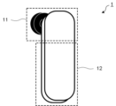
- FIG. 1 is a front view of a beauty device 1;
- FIG. 2 is a rear view of the beauty device 1;
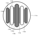
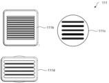
- FIG. 3 is a diagram showing an example of a contact surface 111 on which linear electrodes 112 are arranged;
- FIG. 3 is a diagram showing an example of a contact surface 111 on which linear electrodes 112 are arranged;
- FIG. 4 is a diagram showing an example of a contact surface 111 on which curved electrodes 112 are arranged;
- FIG. 4 is a diagram showing an example of a contact surface 111 on which curved electrodes 112 are arranged;
- FIG. 4 is a diagram showing an example of a contact surface 111 on which electrodes 112 without straight portions 113 are arranged;
- FIG. 4 is a diagram showing an example of a contact surface 111 on which electrodes 112 without straight portions 113 are arranged; 2 is a block diagram showing the hardware configuration of beauty device 1. FIG. 2 is a functional block diagram showing functions of the beauty device 1. FIG. 4 is an activity diagram showing an example of information processing by the beauty device 1. FIG.
- the program for realizing the software appearing in this embodiment may be provided as a non-transitory computer-readable medium (Non-Transitory Computer-Readable Medium), or may be downloaded from an external server. It may be provided as possible, or may be provided so that the program is activated on an external computer and the function is realized on the client terminal (so-called cloud computing).
- the term “unit” may include, for example, a combination of hardware resources implemented by circuits in a broad sense and software information processing that can be specifically realized by these hardware resources.
- various information is handled in the present embodiment, and these information are, for example, physical values of signal values representing voltage and current, and signal values as binary bit aggregates composed of 0 or 1. It is represented by high and low, or quantum superposition (so-called quantum bit), and communication and operation can be performed on a circuit in a broad sense.
- a circuit in a broad sense is a circuit realized by at least appropriately combining circuits, circuits, processors, memories, and the like.
- Application Specific Integrated Circuit ASIC
- Programmable Logic Device for example, Simple Programmable Logic Device (SPLD), Complex Programmable Logic Device (CPLD), and field It includes a programmable gate array (Field Programmable Gate Array: FPGA)).
- Hardware Configuration Section 1 describes the hardware configuration of the beauty device 1 .
- FIG. 1 is a front view of the beauty device 1.
- FIG. 2 is a rear view of the beauty device 1.
- FIG. 1 is a front view of the beauty device 1.
- FIG. 2 is a rear view of the beauty device 1.
- the beauty device 1 is composed of an action section 11 and a grip section 12 as its support.
- the action part 11 is configured to operate while contacting the user's skin, and is provided at one end in the longitudinal direction of the grip part 12 .
- the working part 11 has a contact surface 111 .
- a user can apply stimulation to the skin via the contact surface 111 of the beauty device 1 .
- the contact surface 111 comprises a plurality of electrodes 112 arranged such that adjacent electrodes 112 have different polarities, and through these electrodes 112, electrical stimulation such as high frequency is applied to the user's skin. Also, it detects whether the contact surface 111 is in contact with the skin via the electrode 112 .
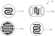
- FIGS. 3 and 4 are diagrams showing an example of the contact surface 111 on which the linear electrodes 112 are arranged.
- the electrode 112 has a linear portion 113 on its outer periphery.
- the contact surface 111 has regions 114 arranged such that there are a plurality of places where the shortest distance between the electrodes 112 is a predetermined length in the plurality of electrodes 112 facing each other. Further description will be made below using specific examples.
- a rectangular region 114a is provided by arranging the straight portion 113a of the electrode 112a and the straight portion 113b of the electrode 112b such that the shortest distance is a predetermined length. That is, the straight portion 113 is arranged parallel to the straight portion 113 on the outer circumference of the other electrode 112 .
- the linear portion 113 preferably has a length of at least 10 mm or more, and the predetermined length is preferably 1 mm or more and 6 mm or less.
- the length of the portion of the electrode 112 forming the region 114 that is in contact with the region 114 is preferably 10 mm or longer. That is, it is preferable that the length of one side of the region 114 formed by the electrode 112 having the straight portion 113 is 10 mm or more.
- the number of electrodes 112 arranged on the contact surface 111 may be 10 or more (contact surface 111b), or the areas of the electrodes 112 may be substantially the same (contact surface 111c and contact surface 111b). 111d).
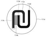
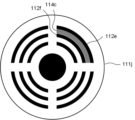
- FIGS. 5 and 6 are diagrams showing an example of the contact surface 111 on which the curved electrodes 112 are arranged.
- the electrode 112 has a linear portion 113 on part of the outer periphery, and in the example of the contact surface 111e, electrodes 112c and 112d of the same shape are arranged to face each other.
- the contact surface 111e is arranged such that the linear portion 113c of the electrode 112c and the linear portion 113d of the electrode 112d are parallel, and has a region 114b.
- each electrode is arranged such that the distance between electrodes 112 arranged on contact surface 111 is constant everywhere. 112 is preferably located. Also, like the contact surface 111h, there may be a portion other than the region 114 where the shortest distance between the electrodes is not the predetermined length.
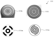
- FIG. 7 and 8 are diagrams showing an example of the contact surface 111 on which the electrode 112 without the straight portion 113 is arranged. As shown in FIG. 7, even if the arranged electrodes 112e and 112f do not have the straight portion 113, they should be arranged so that there are a plurality of places where the shortest distance between the electrodes is a predetermined length. is preferred.
- the contact surface 111j shown in FIG. 7 has a curved region 114c, and the width of the region 114c is constant.
- an annular electrode 112 may be arranged on the contact surface 111 (contact surface 111k, contact surface 111l, and contact surface 111m), or may be spirally arranged. (contact surface 111o).
- the electrodes In this way, by arranging the electrodes so that the distance between them is kept constant, the skin can be stimulated evenly over a wide area.
- the grip part 12 is a bar-shaped part grasped by the user.
- the grip part 12 may be provided with an operation button (input part 13) operated by the user when starting or ending the operation of the beauty device 1 or when deciding the treatment mode.
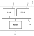
- FIG. 9 is a block diagram showing the hardware configuration of the beauty device 1. As shown in FIG.
- the beauty device 1 includes an input unit 13 , a storage unit 14 and a control unit 15 , and these components are electrically connected via a communication bus 16 inside the beauty device 1 . Each component will be further described.
- the input unit 13 may be included in the housing of the beauty device 1 or may be externally attached.
- the input unit 13 is a switch button.
- the input unit 13 receives an operation input made by the user.
- the input is transferred as a command signal to the control unit 15 via the communication bus 16, and the control unit 15 can perform predetermined control and calculation as necessary.
- the storage unit 14 stores various information defined by the above description.
- This may be, for example, a storage device such as a solid state drive (SSD) that stores various programs related to the beauty device 1 executed by the control unit 15, or a temporary storage device related to program calculation.
- SSD solid state drive
- RAM Random Access Memory
- a combination of these may also be used. That is, hardware resources such as the storage device and memory described above function as the storage unit 14 .
- control unit 15 The control unit 15 processes and controls overall operations related to the beauty device 1 .
- the control unit 15 is, for example, a central processing unit (CPU) (not shown).
- the control unit 15 realizes various functions related to the beauty device 1 by reading a predetermined program stored in the storage unit 14 .
- the CPU as the control unit 15, accesses information stored in the storage unit 14 and executes various functions described later based on the read information. That is, information processing by software (stored in the storage unit 14) is specifically realized by hardware (control unit 15), and each function unit (see FIG. 5) included in the control unit 15 executes can be These are further detailed in the next section.
- the control unit 15 is not limited to a single unit, and may be implemented to have a plurality of control units 15 for each function. A combination thereof may also be used.
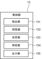
- FIG. 10 is a functional block diagram showing functions of the beauty device 1. As shown in FIG. As described above, information processing by software (stored in the storage unit 14 ) is specifically realized by hardware (control unit 15 ), and can be executed as each functional unit included in the control unit 15 .
- the beauty device 1 (the control unit 15) includes a detection unit 151, an adjustment unit 152, a determination unit 153, a specification unit 154, and an output unit 155 as functional units.
- the detection unit 151 is configured to be able to execute the detection step.
- the detection unit 151 detects whether or not the electrodes 112 arranged on the contact surface 111 of the beauty device 1 come into contact with the skin. Further, the detection unit 151 detects the current value of the output power, and determines the ratio of the electrode 112 contacting the treatment target with respect to the entire surface of the electrode 112 .
- the adjustment unit 152 is configured to be able to execute adjustment steps.
- the adjuster 152 adjusts the power output to the treatment target.
- the decision unit 153 is configured to be able to execute the decision step.
- An output standard for power to be output to a treatment target is determined. Note that the output criteria determined by the determination unit 153 are stored in the storage unit 14 .
- the specifying unit 154 is configured to be able to execute the specifying step.
- the specifying unit 154 specifies the amount of current for each region 114 when the contact surface 111 has a plurality of regions 114 .
- the output unit 155 is configured to be able to execute the output step. In the output step, the output unit 155 outputs power to the treatment target.
- FIG. 11 is an activity diagram showing an example of information processing by the beauty device 1.
- the information processing method comprises the following steps. Note that the order of the following processes can be changed as appropriate, and a plurality of processes may be executed simultaneously, or not all of them need to be executed.
- the user When using the beauty device 1, the user applies lotion, milky lotion, etc., activates the beauty device 1, and selects an arbitrary treatment mode.
- the cosmetic device 1 having two electrodes 112 arranged on the contact surface 111 is used (see FIG. 1).
- an output standard is set when the entire surface of the electrode 112 is brought into contact with the skin.
- the user brings the beauty device 1 into contact with the skin so that the entire electrode 112 touches the skin.
- the detection unit 151 detects that the entire surface of the electrode 112 is in contact with the treatment target, the output unit 155 outputs power of a preset voltage (A101).
- the determination unit 153 determines the current value output at this time as an output reference when the entire surface is in contact with the treatment target (A102). As a result, it is possible to record the skin condition when the beauty device 1 is in use, as the electric resistance changes according to the user's skin type and cosmetics applied to the skin. Note that the output criteria may be set in advance.
- the user can start treatment using the beauty device 1.
- the detection unit 151 detects that the beauty device 1 touches the user's skin
- the output unit 155 outputs power to apply a predetermined beauty effect (A103).
- the detection unit 151 detects the contact ratio of the entire surface of the electrode 112 to the treatment target. Specifically, when the current value output at this time is lower than the reference value determined in A102, the detection unit 151 newly calculates the ratio of the current value to the output reference in A103, the surface of the electrode 112. It is detected as the ratio of contact with the treatment target to the whole. For example, an output reference power is applied, and the reference current value that actually flows is set to "1". At this time, when the current value actually output at A103 is 0.5, 50% of the entire surface of the electrode 112 arranged on the contact surface 111 is in contact with the treatment target. In this way, the detection unit 151 detects the contact rate of the treatment target with respect to the entire surface of the electrode 112 based on the comparison between the determined output reference and the current value of the output power.
- the adjusting unit 152 adjusts the power so that the amount of current decreases as the contact ratio decreases, and the output unit 155 continues to output the adjusted power for a predetermined time (A105).
- the adjustment unit 152 adjusts the output power as follows according to the ratio of the contact area. (1) When the contact ratio is 90% or more, output power of 100% of the output standard. (2) When the contact ratio is 60% or more and less than 90%, the power of 85% or more and less than 95% of the output standard is output. Preferably, the power output is 90% of the output standard. (3) When the contact ratio is 40% or more and less than 60%, the power of 75% or more and less than 85% of the output standard is output. Preferably, the power output is 80% of the output standard. (4) When the contact ratio is 20% or more and less than 40%, the power of 55% or more and less than 75% of the output standard is output. Preferably, the power output is 60% of the output standard. (5) If the contact ratio is 19% or less, output power equal to or greater than 35% and less than 55% of the output standard. Preferably, the power output is 40% of the output standard.
- the area where the skin is in contact with the electrode 112 is detected, and the power is adjusted to the output according to the contact ratio (contact area) with the skin.
- the contact ratio contact area
- the area of contact with the contact surface 111 is small, such as when a part with many irregularities such as the nose and chin is to be treated, current flows intensively in the contact area, but the amount of current is reduced. It is possible to prevent the temperature from rising rapidly.
- the determining unit 153 determines the output reference for each area 114 by periodically outputting power to different areas 114 (A102). For example, as shown in FIG. 3, when there are four regions 114 (regions 114a, 114b, 114c, and 114d), the output unit 155 outputs a state in which all the regions 114 are in contact with the treatment target. , and periodically outputs power to each region 114 .
- the determination unit 153 applies a predetermined electric power to the skin, sets the current value output in 0.01 second elapsed time after the start of output as the reference current value actually flowing through the skin, Determines the output criteria for In other words, this reference current value becomes the output reference for each region 114 .
- A103 when the electrode 112 touches the skin again, power is periodically output to each region 114, similarly to when the output reference was determined. , the amount of current for each region 114 is specified. For example, when the reference current value (output reference) of each region 114 is set to "1", the output unit 155 outputs a current value of "1" to each region 114 for 0.01 seconds.
- 0.01 second is output for each of the four areas 114 .
- one cycle takes 0.04 seconds as follows. (1) Output target from output start to 0.01 second: area 114a (2) Output target from 0.01 seconds to 0.02 seconds: area 114b (3) Output target from 0.02 seconds to 0.03 seconds: area 114c (4) Output target from 0.03 seconds to 0.04 seconds: area 114e
- the current value output from 0.01 seconds after the start of output is 1, and the current value output from 0.01 seconds after the start of output to 0.02 seconds is 0.5. , it is specified that the entire surface of the region 114b that is the output target from 0.01 seconds to 0.02 seconds is not in contact with the treatment target.
- the detection unit 151 determines that the current value output from 0.01 seconds to 0.02 seconds is a current value that is 50% of the reference current value “1” that is the output reference. Therefore, it is determined that the contact ratio of this region 114 to the entire surface is 50%.
- the adjustment unit 152 adjusts the power so that the amount of current that is output from 0.05 seconds after the cycle starts anew to 0.06 seconds becomes 80% of the output reference ( A104). Similarly, in the third cycle, the amount of current output from 0.09 seconds to 0.1 seconds is also adjusted.
- the detection unit 151 detects the contact ratio for each region 114 based on the comparison between the output reference for each region 114 and the current value for each identified region 114, and the adjustment unit 152 detects the contact ratio for each region 114. every time, the power is adjusted to the output corresponding to the contact ratio (A105). In addition, by periodically repeating the output in this way, the contact ratio can be detected for each area 114 even if the area 114 to be output cannot be individually recognized for each time unit during the period. If the process in A105 has been executed for a predetermined time, the process may be returned to A103 and repeated, and if the cycle is repeated a predetermined number of times, the process may be returned to A103.
- the determining unit 153 determines the output reference for each area 114 by outputting the power for each area 114, and the detecting unit 151 outputs power for each area 114.
- a contact rate can be detected.
- the detection unit 151 can detect the contact ratio for each region 114 even if power is not periodically output.
- the electrodes 112 function both to detect contact with the skin and to apply electrical stimulation. Contact availability may be detected via a light receiving element.
- the light receiving elements are arranged at regular intervals of 1 mm or more and 4 mm or less on the contact surface 111 on which the linear electrodes 112 (see FIGS. 3 and 4) are arranged, for example. Specifically, they are 1, 2, 3, and 4 mm, and may be within a range between any two of the numerical values exemplified here.
- the detection unit 151 determines that the entire surface of the electrode 112 is out of contact when the amount of light received by the light receiving element is higher than the threshold. For example, assume that three light receiving elements are arranged between the electrodes.
- the detection unit 151 determines that the light receiving elements are out of contact, and the area in contact with the electrode 112 is one-third. Determine that there is. Thus, in A104, the detection unit 151 determines the ratio of the contact area by the ratio of the number of light receiving elements determined to be non-contact to the total number of light receiving elements arranged on the surface of the contact surface 111. To detect.
- the light emitting elements may be arranged at predetermined intervals together with the light receiving elements.
- the detection unit 151 determines that the amount of light reflected from the light-emitting element is small and the light-receiving element is not in contact with the skin. In this manner, the detection unit 151 may determine whether or not the electrode 112 is in contact by measuring the reflection from the light emitting element.
- the electrodes 112 are arranged so that the skin can be stimulated evenly over a wide area. If a part of the skin is not in contact with the skin, the electric current may flow intensively in the contact part, resulting in excessive heat. By adjusting the output according to the needs, it can be used more safely by general users with peace of mind.
- the aspect of this embodiment may be a program.
- the program causes the computer to execute each step of the beauty device 1 .
- the beauty device has a contact surface, the contact surface is provided with a plurality of electrodes, and the plurality of electrodes facing each other has a plurality of locations where the shortest distance between the electrodes is a predetermined length.
- An object having regions arranged in it.
- the length of the portion of the electrodes that make up the region and that is in contact with the region is 10 mm or more.
- the electrode has a straight portion on its outer circumference, and the straight portion is parallel to the straight portion on the outer circumference of the other electrode. , wherein the linear portion has a length of 10 mm or more, and the areas of the electrodes are substantially the same.
- control unit is configured to further execute a determination step, and in the determination step, the output is made while the entire surface is in contact with the treatment target.
- a current value is determined as an output criterion when the entire surface is in contact with the treatment target, and in the detecting step, based on a comparison between the determined output criterion and the current value of the output power, the current value of the electrode. Detecting the contact rate of the treatment target with respect to the entire surface.
- the detection step includes an output reference set for each region and an output power output for each region. Based on the comparison with the current value, the contact ratio to the treatment target with respect to the entire surface of the region is detected, and in the adjustment step, the power is adjusted to the output corresponding to the contact ratio for each region.
- control unit is configured to further execute a determining step and a specifying step, and in the determining step, periodically outputting the power to different regions. Then, the output reference for each region is determined, the identifying step identifies the current amount for each region based on the current value of the power for each time, and the detecting step determines the output reference and , detecting the contact ratio for each region based on a comparison with the identified current value for each region.
- control unit is configured to further execute a specifying step, and in the determining step, by outputting the power for each region, in the identifying step, outputting the electric power in each region to identify the amount of current in each region; and in the detecting step, the determined output criterion and the identified Detecting the contact ratio for each region based on a comparison with a current value.
Landscapes
- Health & Medical Sciences (AREA)
- Engineering & Computer Science (AREA)
- Biomedical Technology (AREA)
- Nuclear Medicine, Radiotherapy & Molecular Imaging (AREA)
- Radiology & Medical Imaging (AREA)
- Life Sciences & Earth Sciences (AREA)
- Animal Behavior & Ethology (AREA)
- General Health & Medical Sciences (AREA)
- Public Health (AREA)
- Veterinary Medicine (AREA)
- Electrotherapy Devices (AREA)
Priority Applications (1)
| Application Number | Priority Date | Filing Date | Title |
|---|---|---|---|
| CN202280054498.2A CN117858740A (zh) | 2021-09-30 | 2022-08-10 | 美容装置、计算机程序以及信息处理方法 |
Applications Claiming Priority (2)
| Application Number | Priority Date | Filing Date | Title |
|---|---|---|---|
| JP2021161876A JP7762532B2 (ja) | 2021-09-30 | 2021-09-30 | 美容装置、プログラム及び情報処理方法 |
| JP2021-161876 | 2021-09-30 |
Publications (1)
| Publication Number | Publication Date |
|---|---|
| WO2023053734A1 true WO2023053734A1 (ja) | 2023-04-06 |
Family
ID=85782309
Family Applications (1)
| Application Number | Title | Priority Date | Filing Date |
|---|---|---|---|
| PCT/JP2022/030540 Ceased WO2023053734A1 (ja) | 2021-09-30 | 2022-08-10 | 美容装置、プログラム及び情報処理方法 |
Country Status (3)
| Country | Link |
|---|---|
| JP (1) | JP7762532B2 (enExample) |
| CN (1) | CN117858740A (enExample) |
| WO (1) | WO2023053734A1 (enExample) |
Families Citing this family (2)
| Publication number | Priority date | Publication date | Assignee | Title |
|---|---|---|---|---|
| JP2023080750A (ja) * | 2021-11-30 | 2023-06-09 | マクセル株式会社 | 美容装置 |
| KR20250156632A (ko) * | 2024-04-25 | 2025-11-03 | 주식회사 에이피알 | 피부 접촉을 감지할 수 있는 피부 관리 장치 |
Citations (5)
| Publication number | Priority date | Publication date | Assignee | Title |
|---|---|---|---|---|
| JP2004526517A (ja) * | 2001-04-06 | 2004-09-02 | マッティオリ エンジニアリング リミテッド | 経皮吸収促進装置 |
| JP2013534167A (ja) * | 2010-08-19 | 2013-09-02 | シネロン メディカル リミテッド | 個人美容皮膚治療のための電磁気エネルギーアプリケーター |
| JP2017502748A (ja) * | 2013-12-20 | 2017-01-26 | ロレアル | 独立した電流管理を備えたイオン導入デバイス |
| WO2021020270A1 (ja) * | 2019-07-31 | 2021-02-04 | ヤーマン株式会社 | 美容機器 |
| WO2021167109A1 (ja) * | 2020-04-27 | 2021-08-26 | ヤーマン株式会社 | 美容機器および電流制御方法 |
-
2021
- 2021-09-30 JP JP2021161876A patent/JP7762532B2/ja active Active
-
2022
- 2022-08-10 CN CN202280054498.2A patent/CN117858740A/zh active Pending
- 2022-08-10 WO PCT/JP2022/030540 patent/WO2023053734A1/ja not_active Ceased
Patent Citations (5)
| Publication number | Priority date | Publication date | Assignee | Title |
|---|---|---|---|---|
| JP2004526517A (ja) * | 2001-04-06 | 2004-09-02 | マッティオリ エンジニアリング リミテッド | 経皮吸収促進装置 |
| JP2013534167A (ja) * | 2010-08-19 | 2013-09-02 | シネロン メディカル リミテッド | 個人美容皮膚治療のための電磁気エネルギーアプリケーター |
| JP2017502748A (ja) * | 2013-12-20 | 2017-01-26 | ロレアル | 独立した電流管理を備えたイオン導入デバイス |
| WO2021020270A1 (ja) * | 2019-07-31 | 2021-02-04 | ヤーマン株式会社 | 美容機器 |
| WO2021167109A1 (ja) * | 2020-04-27 | 2021-08-26 | ヤーマン株式会社 | 美容機器および電流制御方法 |
Also Published As
| Publication number | Publication date |
|---|---|
| JP2023051298A (ja) | 2023-04-11 |
| JP7762532B2 (ja) | 2025-10-30 |
| CN117858740A (zh) | 2024-04-09 |
Similar Documents
| Publication | Publication Date | Title |
|---|---|---|
| WO2023053734A1 (ja) | 美容装置、プログラム及び情報処理方法 | |
| CN113995496B (zh) | 高频能量传输装置 | |
| US4813412A (en) | Automatic system for an epilator device | |
| JP7387397B2 (ja) | 美容機器 | |
| KR102143819B1 (ko) | 피부 관리 장치 및 그 피부 관리 장치의 제어 방법 | |
| JP7235862B2 (ja) | 美容機器および電流制御方法 | |
| EP3613376A1 (en) | A handheld device for performing a treatment operation on skin | |
| CN112236193B (zh) | 用于改进的皮肤紧致的人工智能 | |
| JP6885646B2 (ja) | スキンケア装置 | |
| CN114144225A (zh) | 美容设备 | |
| US12138451B2 (en) | Adaptive transdermal iontophoretic introduction system for beauty field | |
| KR20170134897A (ko) | 고주파 미용기기 | |
| KR20160101151A (ko) | 독립적인 전류 관리를 갖는 이온토포레틱 디바이스 | |
| KR102195322B1 (ko) | 미용 기구 | |
| EP4643932A1 (en) | Cosmetic procedure device having contact detection sensor, and control method therefor | |
| CN107800406B (zh) | 高频脉冲刺激信号生成方法、脉冲刺激方法及设备 | |
| JP2023051298A5 (enExample) | ||
| CN114534091A (zh) | 利用电场抑制肿瘤增殖的设备及其控制方法和装置 | |
| EP4385443A1 (en) | Intense pulse light skin or hair care device | |
| JP2004129866A (ja) | 電子トリートメント装置 | |
| JP6618098B1 (ja) | 電極掃除具 | |
| KR20220087398A (ko) | 임플란트 시스템 및 임플란트 시스템의 동작 방법 | |
| JP7671980B2 (ja) | 生体電気供給装置 | |
| KR102340613B1 (ko) | 가변 길이 빗살을 가지는 빗 | |
| US12387832B2 (en) | User aware microcurrent therapy device |
Legal Events
| Date | Code | Title | Description |
|---|---|---|---|
| 121 | Ep: the epo has been informed by wipo that ep was designated in this application |
Ref document number: 22875609 Country of ref document: EP Kind code of ref document: A1 |
|
| WWE | Wipo information: entry into national phase |
Ref document number: 202280054498.2 Country of ref document: CN |
|
| NENP | Non-entry into the national phase |
Ref country code: DE |
|
| 122 | Ep: pct application non-entry in european phase |
Ref document number: 22875609 Country of ref document: EP Kind code of ref document: A1 |