WO2023053545A1 - Electrode current collecting foil, electrode, battery, method for manufacturing electrode current collecting foil, and method for manufacturing battery - Google Patents
Electrode current collecting foil, electrode, battery, method for manufacturing electrode current collecting foil, and method for manufacturing battery Download PDFInfo
- Publication number
- WO2023053545A1 WO2023053545A1 PCT/JP2022/016970 JP2022016970W WO2023053545A1 WO 2023053545 A1 WO2023053545 A1 WO 2023053545A1 JP 2022016970 W JP2022016970 W JP 2022016970W WO 2023053545 A1 WO2023053545 A1 WO 2023053545A1
- Authority
- WO
- WIPO (PCT)
- Prior art keywords
- positive electrode
- current collecting
- electrode
- mark
- negative electrode
- Prior art date
Links
- 239000011888 foil Substances 0.000 title claims abstract description 51
- 238000004519 manufacturing process Methods 0.000 title claims description 52
- 238000000034 method Methods 0.000 title claims description 22
- 238000004804 winding Methods 0.000 claims abstract description 78
- 239000011149 active material Substances 0.000 claims abstract description 8
- 239000000463 material Substances 0.000 claims description 84
- 239000012212 insulator Substances 0.000 claims description 12
- 238000005520 cutting process Methods 0.000 claims description 11
- 239000003792 electrolyte Substances 0.000 claims description 10
- 238000007373 indentation Methods 0.000 claims description 3
- 238000003780 insertion Methods 0.000 description 69
- 230000037431 insertion Effects 0.000 description 69
- 230000000694 effects Effects 0.000 description 18
- 238000007789 sealing Methods 0.000 description 12
- 239000007774 positive electrode material Substances 0.000 description 9
- 229910000838 Al alloy Inorganic materials 0.000 description 8
- 229910052782 aluminium Inorganic materials 0.000 description 8
- XAGFODPZIPBFFR-UHFFFAOYSA-N aluminium Chemical compound [Al] XAGFODPZIPBFFR-UHFFFAOYSA-N 0.000 description 8
- NJPPVKZQTLUDBO-UHFFFAOYSA-N novaluron Chemical compound C1=C(Cl)C(OC(F)(F)C(OC(F)(F)F)F)=CC=C1NC(=O)NC(=O)C1=C(F)C=CC=C1F NJPPVKZQTLUDBO-UHFFFAOYSA-N 0.000 description 7
- 238000002347 injection Methods 0.000 description 6
- 239000007924 injection Substances 0.000 description 6
- -1 Polyethylene Polymers 0.000 description 5
- 239000007773 negative electrode material Substances 0.000 description 5
- 239000011295 pitch Substances 0.000 description 5
- 239000011347 resin Substances 0.000 description 5
- 229920005989 resin Polymers 0.000 description 5
- WHXSMMKQMYFTQS-UHFFFAOYSA-N Lithium Chemical compound [Li] WHXSMMKQMYFTQS-UHFFFAOYSA-N 0.000 description 4
- 239000004743 Polypropylene Substances 0.000 description 4
- 239000000470 constituent Substances 0.000 description 4
- 230000001678 irradiating effect Effects 0.000 description 4
- 229910052744 lithium Inorganic materials 0.000 description 4
- 230000000149 penetrating effect Effects 0.000 description 4
- RYGMFSIKBFXOCR-UHFFFAOYSA-N Copper Chemical compound [Cu] RYGMFSIKBFXOCR-UHFFFAOYSA-N 0.000 description 3
- 229910000881 Cu alloy Inorganic materials 0.000 description 3
- PXHVJJICTQNCMI-UHFFFAOYSA-N Nickel Chemical compound [Ni] PXHVJJICTQNCMI-UHFFFAOYSA-N 0.000 description 3
- 239000004698 Polyethylene Substances 0.000 description 3
- 229910052802 copper Inorganic materials 0.000 description 3
- 239000010949 copper Substances 0.000 description 3
- 229910052751 metal Inorganic materials 0.000 description 3
- 229920001155 polypropylene Polymers 0.000 description 3
- HBBGRARXTFLTSG-UHFFFAOYSA-N Lithium ion Chemical compound [Li+] HBBGRARXTFLTSG-UHFFFAOYSA-N 0.000 description 2
- 239000011230 binding agent Substances 0.000 description 2
- 239000003575 carbonaceous material Substances 0.000 description 2
- 239000000919 ceramic Substances 0.000 description 2
- 239000002131 composite material Substances 0.000 description 2
- 238000007599 discharging Methods 0.000 description 2
- 230000005611 electricity Effects 0.000 description 2
- 229910001416 lithium ion Inorganic materials 0.000 description 2
- 239000011572 manganese Substances 0.000 description 2
- 239000002184 metal Substances 0.000 description 2
- 238000012986 modification Methods 0.000 description 2
- 230000004048 modification Effects 0.000 description 2
- 239000003960 organic solvent Substances 0.000 description 2
- 230000002093 peripheral effect Effects 0.000 description 2
- 229920000573 polyethylene Polymers 0.000 description 2
- 150000003839 salts Chemical class 0.000 description 2
- 239000000758 substrate Substances 0.000 description 2
- OKTJSMMVPCPJKN-UHFFFAOYSA-N Carbon Chemical compound [C] OKTJSMMVPCPJKN-UHFFFAOYSA-N 0.000 description 1
- PWHULOQIROXLJO-UHFFFAOYSA-N Manganese Chemical compound [Mn] PWHULOQIROXLJO-UHFFFAOYSA-N 0.000 description 1
- 239000002253 acid Substances 0.000 description 1
- 239000000654 additive Substances 0.000 description 1
- 150000004651 carbonic acid esters Chemical class 0.000 description 1
- 239000006182 cathode active material Substances 0.000 description 1
- 229910017052 cobalt Inorganic materials 0.000 description 1
- 239000010941 cobalt Substances 0.000 description 1
- GUTLYIVDDKVIGB-UHFFFAOYSA-N cobalt atom Chemical compound [Co] GUTLYIVDDKVIGB-UHFFFAOYSA-N 0.000 description 1
- 239000008151 electrolyte solution Substances 0.000 description 1
- 229910002804 graphite Inorganic materials 0.000 description 1
- 239000010439 graphite Substances 0.000 description 1
- 238000009413 insulation Methods 0.000 description 1
- 239000005001 laminate film Substances 0.000 description 1
- 229910003002 lithium salt Inorganic materials 0.000 description 1
- 159000000002 lithium salts Chemical class 0.000 description 1
- 229910052748 manganese Inorganic materials 0.000 description 1
- 238000002844 melting Methods 0.000 description 1
- 230000008018 melting Effects 0.000 description 1
- 229910052987 metal hydride Inorganic materials 0.000 description 1
- 229910052759 nickel Inorganic materials 0.000 description 1
- 239000011148 porous material Substances 0.000 description 1
- 238000003825 pressing Methods 0.000 description 1
Images


Classifications
-
- H—ELECTRICITY
- H01—ELECTRIC ELEMENTS
- H01M—PROCESSES OR MEANS, e.g. BATTERIES, FOR THE DIRECT CONVERSION OF CHEMICAL ENERGY INTO ELECTRICAL ENERGY
- H01M4/00—Electrodes
- H01M4/02—Electrodes composed of, or comprising, active material
- H01M4/04—Processes of manufacture in general
-
- H—ELECTRICITY
- H01—ELECTRIC ELEMENTS
- H01M—PROCESSES OR MEANS, e.g. BATTERIES, FOR THE DIRECT CONVERSION OF CHEMICAL ENERGY INTO ELECTRICAL ENERGY
- H01M4/00—Electrodes
- H01M4/02—Electrodes composed of, or comprising, active material
- H01M4/13—Electrodes for accumulators with non-aqueous electrolyte, e.g. for lithium-accumulators; Processes of manufacture thereof
- H01M4/139—Processes of manufacture
-
- H—ELECTRICITY
- H01—ELECTRIC ELEMENTS
- H01M—PROCESSES OR MEANS, e.g. BATTERIES, FOR THE DIRECT CONVERSION OF CHEMICAL ENERGY INTO ELECTRICAL ENERGY
- H01M50/00—Constructional details or processes of manufacture of the non-active parts of electrochemical cells other than fuel cells, e.g. hybrid cells
- H01M50/50—Current conducting connections for cells or batteries
- H01M50/531—Electrode connections inside a battery casing
- H01M50/533—Electrode connections inside a battery casing characterised by the shape of the leads or tabs
-
- H—ELECTRICITY
- H01—ELECTRIC ELEMENTS
- H01M—PROCESSES OR MEANS, e.g. BATTERIES, FOR THE DIRECT CONVERSION OF CHEMICAL ENERGY INTO ELECTRICAL ENERGY
- H01M50/00—Constructional details or processes of manufacture of the non-active parts of electrochemical cells other than fuel cells, e.g. hybrid cells
- H01M50/50—Current conducting connections for cells or batteries
- H01M50/531—Electrode connections inside a battery casing
- H01M50/538—Connection of several leads or tabs of wound or folded electrode stacks
Definitions
- the present invention relates to a current collecting foil for an electrode, an electrode, a battery, a method for manufacturing the current collecting foil for the electrode, and a method for manufacturing a battery.
- the wound charge/discharge body of the battery it is required to appropriately overlap the plurality of terminal portions of the electrodes.
- the current collecting foil of the electrode of the present invention has a current collecting portion to which an active material is joined and wound, and a plurality of terminal portions provided on the side edge along the winding direction of the current collecting portion. ing.
- the terminal portions adjacent to each other along the winding direction are formed with a relatively longer interval on the side closer to the other end of the winding end than on the side closer to the one end of the winding start of the current collecting portion. contains other things.
- the plurality of terminal portions overlap each other in a state in which the current collecting portion is wound. At least one of the terminal portion and the current collecting portion is provided with a mark for distinguishing the terminal portion of the current collecting portion from the other terminal portion.
- the electrode of the present invention has the current collector foil and an active material.
- the active material is bonded to the collector foil.
- a battery of the present invention includes a positive electrode, a negative electrode, an insulator provided between the positive electrode and the negative electrode, and an electrolyte impregnated in the insulator. At least one of the positive electrode and the negative electrode is the electrode.
- a method for manufacturing a current collecting foil for an electrode according to the present invention includes a current collecting portion to which an active material is joined and wound, a plurality of terminal portions provided on a side edge of the current collecting portion along the winding direction, is a method of manufacturing the current collector foil of the electrode by cutting an electrode base material in which a plurality of current collector foils of an electrode having is linearly connected.
- the electrode base material one having the following structure is used.
- the terminal portions adjacent to each other along the winding direction are formed with a relatively longer interval on the side closer to the other end of the winding end than on the side closer to the one end of the winding start of the current collecting portion. contains other things.
- the plurality of terminal portions overlap each other in a state in which the current collecting portion is wound.
- a method for manufacturing a current collector foil for an electrode according to the present invention includes a first step of conveying the electrode base material, a second step of forming the mark, and placing the electrode base material on the basis of the mark. and a third step of forming the one end portion and the other end portion by cutting in a direction intersecting the conveying direction.
- a positive electrode, a negative electrode, and an insulator provided between the positive electrode and the negative electrode are wound while recognizing at least one mark of the positive electrode mark and the negative electrode mark. It has a step of turning and cutting.
- the current collector foil included in at least one of the positive electrode and the negative electrode the current collector foil manufactured by the method for manufacturing the current collector foil of the electrode is used.
- a plurality of terminal portions of the electrodes can be properly overlapped.
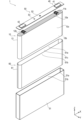
- FIG. 2 is a perspective view showing the battery 1 of the first embodiment;
- FIG. 2 is a cross-sectional perspective view showing the periphery of the negative electrode terminal 42 of the battery 1 of the first embodiment.
- FIG. 2 is a cross-sectional view showing the periphery of the negative electrode terminal 42 of the battery 1 of the first embodiment;
- FIG. 2 is a cross-sectional perspective view showing the periphery of the positive electrode terminal 41 of the battery 1 of the first embodiment.
- FIG. 2 is a cross-sectional view showing the periphery of the positive electrode terminal 41 of the battery 1 of the first embodiment;
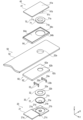
- 2 is an exploded perspective view showing the battery 1 of the first embodiment;
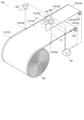
- FIG. 2 is a perspective view showing a charge/discharge body 10 of the battery 1 of the first embodiment;
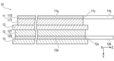
- FIG. 2 is a cross-sectional view showing a part of the charge/discharge body 10 of the battery 1 of the first embodiment; Sectional drawing which shows a part of charging/discharging body 110 of the modification of the battery 1 of 1st Embodiment.
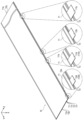
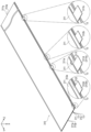
- FIG. 2 is a perspective view showing electrodes (a positive electrode 11 and a negative electrode 12) and a separator 13 of the battery 1 of the first embodiment;
- 4 is an exploded perspective view showing the periphery of a negative electrode terminal 42 of the battery 1 of the first embodiment;
- FIG. 4 is an exploded perspective view showing a lid 52 and a sealing plug 53 of the battery 1 of the first embodiment;
- FIG. 2 is an exploded perspective view showing the periphery of a positive electrode terminal 41 of the battery 1 of the first embodiment
- FIG. FIG. 4 is a perspective view showing a method of manufacturing current collecting foils (positive electrode current collecting layer 11S and negative electrode current collecting layer 12S) of the electrodes (positive electrode 11 and negative electrode 12) of the battery 1 of the first embodiment.
- FIG. 4 is a perspective view showing a method for manufacturing the charge/discharge body 10 of the battery 1 of the first embodiment;
- FIG. 4 is a perspective view showing electrodes (a positive electrode 211 and a negative electrode 212) and a separator 13 of the battery of the second embodiment;
- FIG. 11 is a perspective view showing electrodes (a positive electrode 311 and a negative electrode 312) and a separator 13 of the battery of the third embodiment;
- FIG. 15 illustration of most of the positive electrode tab 11b and the negative electrode tab 12b is omitted.
- the same reference numerals are assigned to the same components, and overlapping descriptions are omitted.
- a left-handed XYZ orthogonal coordinate system having X, Y, and Z axes as coordinate axes is used.
- the arrows on each of the X-axis, Y-axis, and Z-axis indicate the positive directions of the coordinate axes.
- the X-axis is the coordinate axis in the longitudinal direction of the rectangular parallelepiped battery.
- the Y-axis is the coordinate axis in the lateral direction of the battery.
- the Z-axis is the coordinate axis in the height direction of the battery.
- a plane formed by the X and Y axes is called an XY plane
- a plane formed by the Y and Z axes is called a YZ plane
- a plane formed by the X and Z axes is called an XZ plane.
- the positional relationship represented by the XYZ orthogonal coordinate system is merely a relative positional relationship.
- the battery 1 includes a charge/discharge body 10 that charges and discharges electricity, a current collector 20 connected to the charge/discharge body 10, and a current interrupter 30 connected to the current collector 20. , an external terminal 40 connected to the current collector 20 or the current interrupter 30, and an exterior body 50 in which constituent members of the battery 1 are accommodated or attached.
- the battery 1 also includes an insulator 60 that insulates the components of the battery 1 and the exterior body 50 , and a sealing body 70 that seals the components of the battery 1 and the exterior body 50 .
- the charge/discharge body 10 charges and discharges electricity.
- a charge/discharge body 10 shown in FIGS. 2 to 8 includes a positive electrode 11, a negative electrode 12, a separator 13 (insulating member), and an electrolyte .
- the charge/discharge body 10 is formed by winding a component member in which a positive electrode 11, a separator 13, a negative electrode 12, and a separator 13 are laminated in this order and wound into a rectangular parallelepiped shape.
- the positive electrode 11 includes, for example, as shown in FIGS. 7 and 8, a long positive electrode current collecting layer 11S (current collecting foil) and a positive electrode active material layer 11T joined to the positive electrode current collecting layer 11S.
- the positive electrode current collecting layer 11S includes a current collecting portion 11a and a positive electrode tab 11b.
- the current collecting portion 11a is wound.
- a positive electrode active material layer 11T is joined to the current collecting portion 11a.
- the positive electrode active material layer 11T faces, for example, the entire region of the current collecting portion 11a along the lateral direction (Z-axis direction).
- the positive electrode tab 11b protrudes in the lateral direction of the current collector 11a from a side edge 11c along the longitudinal direction (winding direction) of the current collector 11a, for example, as shown in FIGS. ing.
- the positive electrode tab 11b is formed integrally with the current collecting portion 11a.
- a plurality of positive electrode tabs 11b are formed in one current collecting portion 11a.
- the positive electrode tab 11b is configured with a so-called unequal pitch. That is, the interval between the positive electrode tabs 11b adjacent along the winding direction (terminal portions of the same polarity adjacent along the winding direction) is equal to The adjacent positive electrode tab 11b on the side closer to the other end portion 11q of the winding end of the current collecting portion 11a is configured to be relatively longer than the tab 11b. All the positive electrode tabs 11b are configured such that the distance between them becomes relatively longer from one end portion 11p of the current collecting portion 11a toward the other end portion 11q. For this reason, even if the total length of one round of the positive electrode 11 increases each time the constituent members of the charge-discharge body 10 are wound, all the positive electrode tabs 11b are appropriate when the current collecting portion 11a is wound. overlaps with
- the interval between the adjacent positive electrode tabs 11b along the winding direction is configured to be relatively longer from the one end portion 11p of the current collecting portion 11a toward the other end portion 11q. Any configuration including That is, for all the positive electrode tabs 11b, the interval between adjacent positive electrode tabs 11b along the winding direction is not limited to relatively longer from one end portion 11p of the current collecting portion 11a toward the other end portion 11q.
- the positive electrode tabs 11b adjacent to each other along the winding direction may alternately repeat an even pitch and an uneven pitch from one end portion 11p of the current collecting portion 11a toward the other end portion 11q. .
- the positive electrode tab 11d (one of the plurality of positive electrode tabs 11b as a mark) is provided with a mark as shown in FIG.
- the mark is formed by making the shape of the positive electrode tab 11d different from the shape of the other positive electrode tabs 11b.
- the mark is the outer shape of the positive electrode tab 11d that is different from that of the other positive electrode tabs 11b.
- the positive electrode tab 11d located closest to one end portion 11p of the current collecting portion 11a is smaller than the other positive electrode tabs 11b of the current collecting portion 11a. It is composed by being
- the positive electrode tab 11b and the positive electrode tab 11d may each be formed in a trapezoidal shape, and the mark may be configured by varying the length ratio of a pair of opposite sides (lower side and upper side). That is, the mark may be configured by making the ratio of the length of the lower side and the upper side of the positive electrode tab 11d (mark) different from the ratio of the length of the lower side and the upper side of the positive electrode tab 11b.
- the size of the corners of the positive electrode tab 11b and the positive electrode tab 11d may be made different to form a mark. That is, the corners of the positive electrode tab 11d (mark) and the positive electrode tab 11b are curved so that the radius of curvature of the corners of the positive electrode tab 11d and the radius of curvature of the corners of the positive electrode tab 11b are made different to constitute the mark.
- the mark provided on the positive electrode tab 11b may be configured to distinguish any one positive electrode tab 11b from the other positive electrode tabs 11b among the plurality of positive electrode tabs 11b formed on the current collecting portion 11a. That is, the positive electrode tab 11b having the mark is not limited to the first positive electrode tab 11b positioned at the winding start of the current collecting portion 11a.
- the positive electrode tab 11b having the mark may be the positive electrode tab 11b positioned at the winding end of the current collecting portion 11a or the positive electrode tab 11b positioned at the center of the plurality of positive electrode tabs 11b formed in the current collecting portion 11a.
- the other positive electrode tabs 11b are at least one or more (for example, all) positive electrode tabs 11b other than one positive electrode tab 11b among the plurality of positive electrode tabs 11b provided in the positive electrode current collecting layer 11S.
- the positive electrode tab 11b and the positive electrode tab 11d are examples of the terminal portion.
- the terminal portion may be integrated with the collector portion 11a or may be separate from the collector portion 11a.
- the plurality of terminal portions are provided on side edges (at least one side edge) along the winding direction (longitudinal direction) of the current collecting portion 11a.
- the current collecting portion 11a of the positive electrode 11 is made of, for example, aluminum or an aluminum alloy.
- the positive electrode active material layer 11T contains a positive electrode active material composed of a lithium-containing composite oxide, a binder, a conductive aid, and the like. Lithium (Li) and metal elements such as nickel (Ni), cobalt (Co), manganese (Mn), and lithium (Li) are used for lithium-containing composite oxides.
- the negative electrode 12 includes, for example, as shown in FIGS. 7 and 8, a long negative electrode current collecting layer 12S (current collecting foil) and a negative electrode active material layer 12T joined to the negative electrode current collecting layer 12S.
- the negative electrode current collecting layer 12S includes a current collecting portion 12a and a negative electrode tab 12b.
- the current collecting portion 12a of the negative electrode 12 has a longer width along the lateral direction (Z-axis direction) than the current collecting portion 11a of the positive electrode 11 . Both ends of the current collecting portion 11 a of the positive electrode 11 along the short direction are positioned within the range along the short direction of the current collecting portion 12 a of the negative electrode 12 with the separator 13 interposed therebetween.
- a negative electrode active material layer 12T is joined to the current collector 12a.
- the negative electrode active material layer 12T faces, for example, the entire region of the current collecting portion 12a along the lateral direction (Z-axis direction).
- the negative electrode tab 12b protrudes in the lateral direction of the current collecting portion 12a from the side edge 12c along the longitudinal direction (winding direction) of the current collecting portion 12a. ing.
- the negative electrode tab 12b protrudes in the same direction as the positive electrode tab 11b of the positive electrode 11 when stacked on the positive electrode 11 with the separator 13 interposed therebetween.
- the negative electrode tab 12b is separated from the positive electrode tab 11b of the positive electrode 11 in the state of being laminated with the positive electrode 11 with the separator 13 interposed therebetween.
- the negative electrode tab 12b is formed integrally with the current collector 12a.
- a plurality of negative electrode tabs 12b are formed in one current collecting portion 12a.
- the negative electrode tabs 12b are configured with a so-called unequal pitch. That is, the interval between the adjacent negative electrode tabs 12b along the winding direction is closer to the one end 12p of the winding start of the current collecting portion 12a than the adjacent negative electrode tab 12b at the other end of the winding end of the current collecting portion 12a.
- the adjacent negative electrode tabs 12b on the side closer to the portion 12q are configured to be relatively longer. All the negative electrode tabs 12b overlap each other in the state in which the current collecting portion 12a is wound.
- the interval between the adjacent current collecting portions 12a is relatively longer from one end portion 12p to the other end portion 12q of the negative electrode. Any configuration including the tab 12b may be used.
- the negative electrode tab 12d (one of the plurality of negative electrode tabs 12b) is provided with a mark similarly to the positive electrode tab 11d.
- the mark is configured by making the shape of the negative electrode tab 12d different from the shape of the other negative electrode tabs 12d.
- the mark is the outer shape of the negative electrode tab 12d that is different from that of the other negative electrode tabs 12b.
- the mark is that the negative electrode tab 12d located closest to one end 12p of the current collecting portion 12a is formed smaller than the other negative electrode tabs 12b of the current collecting portion 12a. It is composed by being
- the negative electrode tab 12b and the negative electrode tab 12d may each be formed in a trapezoidal shape, and a mark may be formed by varying the length ratio of a pair of opposite sides (lower side and upper side). That is, the mark may be configured by making the ratio of the length of the lower side to the upper side of the negative electrode tab 12d (mark) different from the ratio of the length of the lower side to the upper side of the negative electrode tab 12b.
- the size of the corners of the negative electrode tab 12b and the negative electrode tab 12d may be made different to form a mark. That is, the corners of the negative electrode tab 12d (mark) and the negative electrode tab 12b are curved so that the radius of curvature of the corners of the negative electrode tab 12d and the radius of curvature of the corners of the negative electrode tab 12b are made different to constitute the mark.
- the mark provided on the negative electrode tab 12b can distinguish any one negative electrode tab 12b from the other negative electrode tabs 12b among the plurality of negative electrode tabs 12b formed on the current collecting portion 12a, similarly to the positive electrode tab 11b. Any configuration is acceptable.
- the other negative electrode tabs 12b are at least one or more (for example, all) negative electrode tabs 12b other than one negative electrode tab 12b among the plurality of negative electrode tabs 12b provided in the negative electrode current collecting layer 12S.
- the negative electrode tab 12b and the negative electrode tab 12d are examples of the terminal portion.
- the terminal portion may be integrated with the collector portion 12a or may be separate from the collector portion 12a.
- the plurality of terminal portions are provided on side edges (at least one side edge) along the winding direction (longitudinal direction) of the current collecting portion 12a.
- the collector 12a of the negative electrode 12 is made of, for example, copper or a copper alloy.
- the negative electrode active material layer 12T contains a negative electrode active material made of a carbon-based material, a binder, a conductive aid, and the like. Graphite, for example, is used as the carbon-based material.
- the separator 13 (insulator) allows lithium ions to pass through while providing insulation between the positive electrode 11 and the negative electrode 12, for example, as shown in FIGS.
- the separator 13 is formed in an elongated shape.
- the separator 13 has a longer width along the lateral direction (Z-axis direction) than the collector portion 11 a of the positive electrode 11 and the collector portion 12 a of the negative electrode 12 .
- Both ends of the current collecting portion 11a of the positive electrode 11 along the short direction are located within the range along the short direction of the separator 13, and both ends of the current collecting portion 12a of the negative electrode 12 along the short direction are located within the range along the short direction of the separator 13.
- the separator 13 is made of a porous material.
- Polyethylene PolyEthylene
- PP Polypropylene
- a heat-resistant insulating member may be used instead of the separator 13 . Ceramics, for example, is used for the heat-resistant insulating member. Such a configuration is a so-called separatorless configuration.
- the electrolyte 14 corresponds to a so-called electrolytic solution. Electrolyte 14 is impregnated in separator 13 .
- the electrolyte 14 contains an organic solvent, a supporting salt, and additives. For example, carbonic acid ester is used as the organic solvent. Lithium salt is used as the supporting salt, for example.
- a charge/discharge body 110 which is a modification of the charge/discharge body 10, will be described with reference to FIG.
- the configuration of the positive electrode 111 is different from the configuration of the positive electrode 11 of the first embodiment.
- the same reference numerals are given to the same configurations as those of the charge/discharge body 10, and the description thereof is omitted.
- the positive electrode active material layer 111T of the charge/discharge body 110 faces a portion of the current collector 11a excluding both ends along the short direction (Z-axis direction).
- a heat-resistant insulating layer 111U of the charge/discharge body 110 is joined to both ends of the collector portion 11a along the width direction and to the base end portion of the positive electrode tab 11b.
- the heat-resistant insulating layer 111U contains, for example, ceramics.
- the current collector 20 is connected to the charge/discharge body 10 .
- the current collector 20 shown in FIGS. 2 to 5, 11 and 13 includes a positive current collector 21 and a negative current collector 22.
- FIG. 1 is a diagrammatic representation of the current collector 20 in FIGS. 2 to 5, 11 and 13 .
- the positive electrode current collector plate 21 electrically connects the positive electrode tab 11b of the charge/discharge body 10 and the positive electrode terminal 41 via the current interrupter 30, as shown in FIGS. 4 and 5, for example.
- the positive electrode current collector plate 21 includes a rectangular parallelepiped first base 21a, a rectangular parallelepiped second base 21b, and the first base 21a and the second base 21b arranged stepwise. It includes a connecting portion 21c that connects to the , with different heights.
- a concave portion 21d is formed in the upper surface of the second base portion 21b (the surface on the Z-axis positive direction side) by forming the second base portion 21b to be thin.
- a fragile portion 21e which is a fragile portion recessed in a ring shape, is formed in the center of the recess 21d.
- the positive collector plate 21 is made of, for example, aluminum or an aluminum alloy.
- the negative electrode current collector plate 22 electrically connects the negative electrode tab 12b of the charge/discharge body 10 and the negative electrode terminal 42, for example, as shown in FIGS.
- the negative electrode current collector plate 22 includes a rectangular parallelepiped plate-shaped base portion 22a and an insertion hole 22b passing through the base portion 22a.
- the insertion portion 42 b of the negative electrode terminal 42 is inserted into the insertion hole 22 b of the negative electrode current collector plate 22 .
- the negative electrode current collector plate 22 is made of, for example, copper or a copper alloy.
- the current interrupter 30 is connected to the current collector 20 and electrically connects the current collector 20 and the positive electrode terminal 41 .
- the current interrupter 30 shown in FIGS. 4, 5 and 13 includes a diaphragm 31, a conductive member 32, and a pair of supports 33. As shown in FIG.
- the diaphragm 31 includes a curved cylindrical body portion 31a, a disk-shaped first joint portion 31b provided on the tip side (Z-axis negative direction side) of the body portion 31a, and a body portion It includes a ring-shaped second joint portion 31c provided on the base end side (the Z-axis positive direction side) of 31a.
- the first joint portion 31 b is joined to the recess 21 d of the positive collector plate 21 .
- the second joint portion 31 c is joined to the conducting member 32 .
- Diaphragm 31 is made of, for example, aluminum or an aluminum alloy.
- the conduction member 32 is formed in a cylindrical shape, as shown in FIG. 13, for example.
- the positive electrode side first insulating plate 62 is joined to the upper surface of the conducting member 32 (the surface on the Z-axis positive direction side).
- a second joint portion 31c of the diaphragm 31 is joined to the peripheral edge of the lower surface of the conducting member 32 (the surface on the Z-axis negative direction side).
- the conducting member 32 is made of, for example, aluminum or an aluminum alloy.
- the support base 33 includes a rectangular main body portion 33a extending in the lateral direction (Y-axis direction) of the battery 1 and both sides of the main body portion 33a in the longitudinal direction (Y-axis direction). and a leg portion 33b extending downward (Z-axis negative direction).
- One support base 33 is provided at each end of the diaphragm 31 along the longitudinal direction (X-axis direction) of the battery 1 .
- the body portion 33 a is attached to the positive electrode side first insulating plate 62 .
- the leg portion 33 b is attached to the second base portion 21 b of the positive electrode current collector plate 21 .
- the support base 33 is made of, for example, insulating resin.
- the external terminal 40 is connected to the current collector 20 or current interrupter 30 .
- the external terminals 40 shown in FIGS. 1-6, 11 and 13 include a positive terminal 41 and a negative terminal 42 .
- the positive terminal 41 is connected to the conducting member 32 of the current interrupter 30, as shown in FIG. 5, for example.
- the positive electrode terminal 41 includes a rectangular parallelepiped plate-shaped base portion 41a, a cylindrical insertion portion 41b projecting downward (Z-axis negative direction) from the base portion 41a, and downward from the periphery of the base portion 41a ( It includes a cylindrical joint portion 41c protruding in the Z-axis negative direction).
- the base 41a is in contact with the base 64a of the positive electrode side second insulating plate 64, for example, as shown in FIG.
- the insertion portion 41 b is inserted into the insertion hole 64 b of the second positive insulating plate 64 , the positive insertion hole 52 a of the lid 52 , the insertion hole 62 b of the first positive insulating plate 62 , and the insertion hole 32 b of the conducting member 32 . .
- the joint portion 41c protrudes downward (Z-axis negative direction) from the insertion hole 32b of the conduction member 32 and is expanded radially outward to be joined to the conduction member 32.
- the joint portion 41c is caulked around the periphery of the insertion hole 32b of the conducting member 32.
- the joint portion 41 c is welded to the periphery of the insertion hole 32 b of the conducting member 32 .
- the positive electrode terminal 41 is made of, for example, aluminum or an aluminum alloy.
- the negative electrode terminal 42 is connected to the negative current collecting plate 22, for example, as shown in FIG.
- the negative electrode terminal 42 includes a rectangular parallelepiped plate-shaped base portion 42a, a cylindrical insertion portion 42b protruding downward (Z-axis negative direction) from the base portion 42a, and downward from the periphery of the base portion 42a ( It includes a cylindrical joint portion 42c protruding in the Z-axis negative direction).
- the base portion 42a is in contact with the base portion 65a of the negative electrode side second insulating plate 65, for example, as shown in FIG.
- the insertion portion 42b is inserted into the insertion hole 65b of the negative electrode-side second insulating plate 65, the negative electrode-side insertion hole 52b of the lid 52, the insertion hole 63b of the negative electrode-side first insulating plate 63, and the insertion hole 22b of the negative current collector plate 22. ing.
- the joint portion 42 c protrudes downward from the insertion hole 22 b of the negative electrode current collector plate 22 and is expanded radially outward to be joined to the negative electrode current collector plate 22 . That is, the joint portion 42 c is caulked around the periphery of the insertion hole 22 b of the negative electrode current collector plate 22 . Furthermore, the joint portion 42 c is welded to the periphery of the insertion hole 22 b of the negative electrode current collector plate 22 .
- the negative electrode terminal 42 is made of, for example, copper or a copper alloy.
- the components of the battery 1 are housed or attached to the exterior body 50 .
- 1 to 6 and 11 to 13 includes a container 51 , a lid 52 and a sealing plug 53 .
- the container 51 accommodates the charge/discharge body 10 and the like covered with an insulating cover 61, as shown in FIGS. 2 and 6, for example.
- the container 51 is configured by a rectangular parallelepiped metal can.
- the container 51 includes, for example, as shown in FIG. 6, an opening 51a opened along the longitudinal direction and a housing portion 51b connected to the opening 51a.
- the container 51 is made of aluminum or an aluminum alloy, for example.
- the lid 52 seals the opening 51a of the container 51, as shown in FIGS. 2 and 6, for example.
- Lid 52 faces one side portion 10 a (side portion) of charge/discharge body 10 where positive electrode 11 , separator 13 , and negative electrode 12 are adjacent to each other.
- the lid 52 is formed of a long plate-shaped metal plate.
- the cover 52 has a positive electrode side insertion hole 52a formed by a circular through hole at one end in the longitudinal direction.
- the insertion portion 41b of the positive electrode terminal 41 is inserted into the positive electrode side insertion hole 52a.
- a negative electrode side insertion hole 52b configured by a circular through hole is formed in the lid 52 on the other end side in the longitudinal direction.
- the insertion portion 42b of the negative electrode terminal 42 is inserted into the negative electrode side insertion hole 52b.
- the lid 52 has an injection hole 52c formed by a circular through hole between the positive electrode side insertion hole 52a and the negative electrode side insertion hole 52b.
- the electrolyte 14 is injected from the lid 52 toward the container 51 through the injection hole 52c.
- the insertion portion 53b of the sealing plug 53 is inserted into the injection hole 52c.
- the lid 52 has a split valve 52d formed in the center in the longitudinal direction. Lid 52 is welded to container 51 .
- the lid 52 is made of aluminum or an aluminum alloy, for example.
- the sealing plug 53 seals the injection hole 52c of the lid 52, for example, as shown in FIG.
- the sealing plug 53 is formed in a cylindrical shape.
- the sealing plug 53 includes a head portion 53a having a relatively large outer diameter and an insertion portion 53b continuous with the head portion 53a and having a relatively small outer diameter.
- a head portion 53 a of the sealing plug 53 is welded to the lid 52 .
- the sealing plug 53 is made of, for example, aluminum or an aluminum alloy.
- the insulator 60 insulates the components of the battery 1 and the exterior body 50 .
- the insulator 60 shown in FIGS. 2 to 6, 11 and 13 includes an insulating cover 61, a positive electrode-side first insulating plate 62, a negative electrode-side first insulating plate 63, a positive electrode-side second insulating plate 64, and a negative electrode-side second insulating plate.
- An insulating plate 65 is included.
- the insulating cover 61 covers and insulates the charge/discharge body 10, for example, as shown in FIG.
- the insulating cover 61 is a pair of opposing side surfaces (first side surface 61a and second side surface 61b) and between the first side surface 61a (one side surface) and the second side surface 61b (the other side surface) of the charge/discharge body 10. It includes an opening 61c that exposes one side 10a.
- the insulating cover 61 covers the one side portion 10a of the charge/discharge body 10 other than one surface.
- the insulating cover 61 covers the other side portion 10b facing the one side portion 10a of the charge/discharge body 10 and the outer peripheral portion 10c positioned between the one side portion 10a and the other side portion 10b of the charge/discharge body 10. ing.
- the insulating cover 61 is formed into a pentahedral shape by folding a polyhedral sheet into a box shape.
- the insulating cover 61 is made of, for example, polypropylene.
- the positive electrode side first insulating plate 62 insulates the positive electrode collector plate 21 and the conductive member 32 from the lid 52, for example, as shown in FIG.
- the positive electrode side first insulating plate 62 includes a rectangular parallelepiped base 62a, an insertion hole 62b penetrating through the base 62a, and an annular side edge of the base 62a that is separated from the lid 52. It includes a convex portion 62c projecting in the direction.
- the positive current collecting plate 21, the conductive member 32, and the like are accommodated in a space defined by the base portion 62a and the convex portion 62c.
- the insertion portion 41b of the positive electrode terminal 41 is inserted into the insertion hole 62b.
- the positive electrode side first insulating plate 62 is made of, for example, an insulating resin.
- the negative electrode-side first insulating plate 63 insulates the negative electrode collector plate 22 and the lid 52, for example, as shown in FIG.
- the negative electrode side first insulating plate 63 includes a rectangular parallelepiped base 63a, an insertion hole 63b penetrating through the base 63a, and an annular surrounding side edge of the base 63a separated from the lid 52. It includes a convex portion 63c projecting in the direction.
- the negative current collector plate 22 is accommodated in a space defined by the base portion 63a and the convex portion 63c.
- the insertion portion 42b of the negative terminal 42 is inserted into the insertion hole 63b.
- the negative electrode side first insulating plate 63 is made of, for example, an insulating resin.
- the positive electrode side second insulating plate 64 insulates the positive electrode terminal 41 and the lid 52, for example, as shown in FIG.
- the positive electrode side second insulating plate 64 includes a rectangular plate-like base portion 64a, an insertion hole 64b penetrating the base portion 64a, and an annular side edge of the base portion 64a that is separated from the lid 52. It includes a convex portion 64c projecting in the direction.
- the positive electrode terminal 41 is accommodated in a space defined by the base portion 64a and the convex portion 64c.
- the insertion portion 41b of the positive electrode terminal 41 is inserted into the insertion hole 64b.
- the positive electrode side second insulating plate 64 is made of, for example, an insulating resin.
- the negative electrode side second insulating plate 65 insulates the negative electrode terminal 42 and the lid 52, for example, as shown in FIG.
- the negative electrode side second insulating plate 65 includes a rectangular parallelepiped base 65a, an insertion hole 65b penetrating through the base 65a, and an annular side edge of the base 65a that is separated from the lid 52. It includes a convex portion 65c projecting in the direction.
- the negative electrode terminal 42 is accommodated in a space defined by the base portion 65a and the convex portion 65c.
- the insertion portion 42b of the negative terminal 42 is inserted into the insertion hole 65b.
- the negative electrode side second insulating plate 65 is made of, for example, an insulating resin.
- the sealing body 70 seals the constituent members of the battery 1 and the exterior body 50 .
- the sealing body 70 shown in FIGS. 2 to 5, 11 and 13 includes a positive electrode side gasket 71 and a negative electrode side gasket 72. As shown in FIG.
- the positive electrode side gasket 71 insulates the positive electrode side second insulating plate 64 and the lid 52, for example, as shown in FIG.
- the positive electrode side gasket 71 is formed in a cylindrical shape.
- the positive electrode side gasket 71 includes a first insertion portion 71a having a relatively large outer diameter, a second insertion portion 71b continuing from the first insertion portion 71a and having a relatively small outer diameter, and a second insertion portion 71b having a relatively small outer diameter. It includes an insertion hole 71c passing through the first insertion portion 71a and the second insertion portion 71b.
- the first insertion portion 71 a of the positive electrode side gasket 71 is inserted into the insertion hole 64 b of the positive electrode side second insulating plate 64 .
- the second insertion portion 71 b of the positive electrode side gasket 71 is inserted into the positive electrode side insertion hole 52 a of the lid 52 .
- the insertion portion 41b of the positive electrode terminal 41 is inserted into the insertion hole 71c.
- the positive electrode side gasket 71 is made of, for example, insulating and elastic rubber.
- the negative electrode side gasket 72 insulates the negative electrode side second insulating plate 65 and the lid 52, for example, as shown in FIG.
- the negative electrode side gasket 72 is formed in a cylindrical shape.
- the negative electrode side gasket 72 includes a first insertion portion 72a having a relatively large outer diameter, a second insertion portion 72b continuing from the first insertion portion 72a and having a relatively small outer diameter, and a second insertion portion 72b having a relatively small outer diameter. It includes an insertion hole 72c passing through the first insertion portion 72a and the second insertion portion 72b.
- the first insertion portion 72 a of the negative electrode side gasket 72 is inserted into the insertion hole 65 b of the negative electrode side second insulating plate 65 .
- the second insertion portion 72 b of the negative electrode side gasket 72 is inserted into the negative electrode side insertion hole 52 b of the lid 52 .
- the insertion portion 42b of the negative terminal 42 is inserted into the insertion hole 72c.
- the negative electrode side gasket 72 is made of, for example, insulating and elastic rubber.
- FIG. 14 A method of manufacturing the collector foil of the electrode and the battery 1 of the first embodiment will be described with reference to FIGS. 14 and 15.
- FIG. 14 As a method for manufacturing the current collector foil of the electrode, a method for manufacturing a plurality of positive electrode tabs 11b including positive electrode tabs 11d serving as marks, which is a configuration unique to the first embodiment, will be described.
- the manufacturing method of the plurality of negative electrode tabs 12b including the negative electrode tabs 12d serving as marks is the same as the method of manufacturing the plurality of positive electrode tabs 11b including the positive electrode tabs 11d serving as marks, and thus the description thereof is omitted.
- the manufacturing method of the positive electrode current collecting layer 11S (current collecting foil) of the positive electrode 11 of the battery 1 shown in FIG. has a second step of forming the positive electrode tab 11d (mark) in the second step.
- the electrode tab manufacturing apparatus 500 includes a controller 501, a carry-out roller 502, a first take-up roller 503, a second take-up roller 504, a first laser processing machine 505, a second laser processing machine 506, and A third laser processing machine 507 is included.
- the electrode tab manufacturing apparatus 500 laser-processes the positive electrode first base material 11J to form a plurality of positive electrode tabs 11b including a positive electrode tab 11d serving as a mark.
- the controller 501 controls the operations of the carry-out roller 502 , the first winding roller 503 , the second winding roller 504 , the first laser processing machine 505 , the second laser processing machine 506 and the third laser processing machine 507 .
- the positive electrode first base material 11J has an elongated shape, and is formed by bonding a positive electrode active material layer 11T to a positive electrode current collecting layer 11S. In the positive electrode first base material 11J, the positive electrode active material layer 11T shown in FIGS. 7 and 8 is not joined to a pair of longitudinal side edges, and the positive electrode current collecting layer 11S is exposed.
- the positive electrode first base material 11J is wound around an unloading roller 502 having a cylindrical cross section.
- the controller 601 operates the first winding roller 503 and the second winding roller 504 .
- the positive electrode first base material 11J carried out from the carry-out roller 502 is transferred to the first laser processing machine 505, the second laser processing machine 506, and the second laser processing machine 506. 3 Move toward the laser processing machine 507 .
- the first laser processing machine 505 scans one side edge along the longitudinal direction of the positive electrode first base material 11J being conveyed while irradiating it with the laser light L1. A portion corresponding to between adjacent positive electrode tabs 11b along one side edge along the longitudinal direction of the positive electrode first base material 11J is cut and discarded by the laser beam L1.
- the positive electrode tab 11d and the positive electrode tab 11b serving as marks are formed on one side edge along the longitudinal direction of the positive electrode first base material 11J.
- the plurality of positive electrode tabs 11b are formed at uneven pitches.
- One positive electrode tab 11 d serving as a mark is formed for each length of one positive electrode 11 .
- the second laser processing machine 506 scans the other side edge along the longitudinal direction of the positive electrode first base material 11J being conveyed while irradiating it with the laser beam L2. A portion corresponding to between adjacent positive electrode tabs 11b along the other side edge along the longitudinal direction of the positive electrode first base material 11J is cut by the laser beam L2 and discarded.
- the positive electrode tab 11d and the positive electrode tab 11b serving as marks are formed on the other side edge along the longitudinal direction of the positive electrode first base material 11J.
- the third laser processing machine 507 irradiates the center of the moving positive electrode first base material 11J with the laser beam L3.
- the positive electrode first base material 11J is cut into two by the laser beam L3 to form a pair of positive electrode second base materials 11K.
- One of the pair of positive electrode second base materials 11K is wound up by the first winding roller 503 .
- the other positive electrode second base material 11K is wound up by the second winding roller 504. As shown in FIG. That is, the positive electrode first substrate 11J is cut at the center to form two positive electrode second substrates 11K.
- each positive electrode second base material 11K one side edge along the longitudinal direction is formed with a plurality of positive electrode tabs 11b including a positive electrode tab 11d serving as a mark. 7 and 8, the cathode collector layer 11S and the cathode active material layer 11T shown in FIG. 7 and FIG.
- the positive electrode current collecting layer 11S current collecting foil of the positive electrode 11 of the battery 1 shown in FIG. It has a third step of cutting to form one end portion 11p and the other end portion 11q. 15 includes a step of winding the positive electrode 11, the negative electrode 12, and the separator 13 while recognizing the mark of the positive electrode 11 and the mark of the negative electrode 12. are doing.
- the winding device 600 includes a controller 601, a delivery roller 602, a driven roller 603, a first carry-out roller 604, a second carry-out roller 605, a first camera 606, a first adjustment roller 607, a first It includes a driven roller 608 , a cutter 609 , a cutter pedestal 610 , a second camera 611 , a second adjustment roller 612 , a second driven roller 613 and a winding spindle 614 .
- the winding device 600 is equipped with a first winding roller 503 around which the positive electrode second base material 11K is wound and a second winding roller 504 around which the negative electrode second base material 12K is wound.
- the charging/discharging body 10 is formed by winding while recognizing the mark of the positive electrode 11 and the mark of the negative electrode 12 by the winding device 600 .
- the controller 601 controls a first take-up roller 503, a second take-up roller 504, a delivery roller 602, a first carry-out roller 604, a second carry-out roller 605, a first camera 606, a first adjustment roller 607, a cutter 609, a 2 Controls the operation of the camera 611 , the second adjustment roller 612 and the winding spindle 614 .
- the first adjustment roller 607 and the first driven roller 608 are arranged between the delivery roller 602 and the first take-up roller 503 .
- the first camera 606 is arranged near the first adjustment roller 607 .
- a second adjustment roller 612 and a second driven roller 613 are arranged between the delivery roller 602 and the second take-up roller 504 .
- the second camera 611 is arranged near the second adjustment roller 612 .
- Cutter 609 and cutter pedestal 610 are positioned between delivery roller 602 and winding spindle 614 .
- the controller 601 operates the delivery roller 602 .
- the positive electrode second base material 11K carried out from the first take-up roller 503, the separator base material 13K carried out from the first carry-out roller 604, and the second take-up roller 504 carry out
- the negative electrode second base material 12K and the separator base material 13K carried out from the second carry-out roller 605 move toward the cutter 609 and the cutter base 610 .
- the positive electrode second base material 11K, the separator base material 13K, the negative electrode second base material 12K, and the separator base material 13K are stacked in that order, sandwiched between the feed roller 602 and the driven roller 603, and cut by the cutter 609 and the separator base material 13K. Move toward the cutter pedestal 610 .
- the controller 601 operates the first camera 606 to photograph the positive electrode second base material 11K. Based on the photographed image of the positive electrode second base material 11K, the controller 601 adjusts the position of the positive electrode tab 11d formed on the positive electrode second base material 11K to the winding start position of the positive electrode 11 in the charge/discharge body 10. It is determined whether or not it exists at the corresponding position. When the controller 601 determines that the position of the positive electrode tab 11d is not at the corresponding position, the controller 601 determines that the position of the positive electrode tab 11d at the beginning of winding of the positive electrode second base material 11K is misaligned, and changes the position of the positive electrode tab 11d. to adjust.
- the controller 601 operates the first adjustment roller 607 to move the positive electrode second base material 11K sandwiched between the first adjustment roller 607 and the first driven roller 608 toward the cutter 609 and the cutter pedestal 610. Let After the position of the positive electrode tab 11d at the beginning of the winding of the positive electrode second base material 11K is adjusted by the first adjustment roller 607, there is a surplus portion protruding from the delivery roller 602 and the driven roller 603 on the positive electrode second base material 11K. Occur. The controller 601 operates the cutter 609 to cut the surplus portion of the positive electrode second base material 11K together with the cutter pedestal 610 . Under the control of the controller 601, the winding start position of the positive electrode second base material 11K with respect to the charge/discharge body 10 is adjusted using the positive electrode tab 11d corresponding to the winding start position as a mark.
- the controller 601 operates the second camera 611 to photograph the negative electrode second base material 12K. Based on the photographed image of the negative electrode second base material 12K, the controller 601 adjusts the position of the negative electrode tab 12d formed on the negative electrode second base material 12K to the winding start position of the negative electrode 12 in the charge/discharge body 10. It is determined whether or not it exists at the corresponding position. When the controller 601 determines that the position of the negative electrode tab 12d does not exist at the corresponding position, the controller 601 determines that the position of the negative electrode tab 12d at the beginning of the winding of the negative electrode second base material 12K is misaligned, and changes the position of the negative electrode tab 12d. to adjust.
- the controller 601 operates the second adjustment roller 612 to move the negative electrode second base material 12K sandwiched between the second adjustment roller 612 and the second driven roller 613 toward the cutter 609 and the cutter pedestal 610. Let After the position of the negative electrode tab 12d at the beginning of the winding of the negative electrode second base material 12K is adjusted by the second adjusting roller 612, the negative electrode second base material 12K has a surplus portion protruding from the delivery roller 602 and the driven roller 603. Occur. The controller 601 operates the cutter 609 to cut the surplus portion of the negative electrode second base material 12K together with the cutter pedestal 610 . Under the control of the controller 601 described above, the winding start position of the negative electrode second base material 12K with respect to the charge/discharge body 10 is adjusted using the negative electrode tab 12d corresponding to the winding start position as a mark.
- the controller 601 operates the feeding roller 602 to feed the positive electrode second base material 11K, the separator base material 13K, the negative electrode second base material 12K, and the separator base material 13K in a laminated state toward the winding spindle 614. .
- the controller 601 operates the winding spindle 614 to wind the positive electrode second base material 11K, the separator base material 13K, the negative electrode second base material 12K, and the separator base material 13K in a laminated state.
- the positive electrode second base material 11K, the separator base material 13K, the negative electrode second base material 12K, and the separator base material 13K are wound by the winding spindle 614 so as to constitute one charge/discharge body 10 .
- the controller 601 operates the cutter 609 to cut the ends of the wound positive electrode second base material 11K, separator base material 13K, negative electrode second base material 12K, and separator base material 13K.
- the charge/discharge body 10 is removed from the winding spindle 614 .
- the charge/discharge device 10 is accommodated in the container 51 .
- a lid 52 is joined to the container 51 .
- Electrolyte 14 is injected toward container 51 through injection hole 52 c of lid 52 .
- Electrolyte 14 is impregnated in separator 13 .
- a sealing plug 53 is joined to the injection hole 52 c of the lid 52 .
- the positive electrode current collecting layer 11S (current collecting foil) of the positive electrode 11 is provided with a mark for distinguishing between any one of the positive electrode tabs 11b of the current collecting portion 11a and the other positive electrode tabs 11b.
- a mark is formed in the manufacturing method of the positive electrode current collecting layer 11S of the positive electrode 11 of the battery 1.
- the positive electrode 11, the negative electrode 12, and the separator (insulator) are wound while recognizing the mark.
- the charge/discharge body 10 of the battery 1 it is possible to prevent the position of the positive electrode tab 11d at the start of winding of the positive electrode 11 from shifting. Therefore, in the charge/discharge body 10, the plurality of positive electrode tabs 11b of the positive electrode 11 can be properly overlapped.
- a charge/discharge body 10 of the battery 1 is configured by winding a positive electrode 11, a separator 13, and a negative electrode 12. As shown in FIG. Therefore, the battery 1 can satisfy the desired battery performance by appropriately overlapping the plurality of positive electrode tabs 11b.
- the cutting position of the positive electrode 11 can be correctly recognized based on the mark.
- the cutting position of the positive electrode 11 can be correctly recognized based on the mark.
- the positive electrode tab 11b is formed on the positive electrode first base material 11J (electrode base material)
- the formed positive electrode tab 11b can be removed based on the mark. Able to recognize the state correctly.
- the marks are the positive electrode tab 11d (first one) closest to one end portion 11p (the winding start portion) of the current collecting portion 11a and the other positive electrode tabs 11b (for example, the second to fifteenth positive electrode tabs). A total of 14 positive electrode tabs 11b are formed to be distinguishable.
- the mark is formed in the method for manufacturing the positive electrode current collecting layer 11S of the positive electrode 11, in the second step. That is, the first positive electrode tab 11d, which is closest to one end portion 11p of the current collecting portion 11a and is the easiest to distinguish, is used as a mark. According to such a configuration, the mark can be configured based on a simple and easy-to-distinguish method.
- the mark is the external shape of the positive electrode tab 11d (the first tab) closest to the one end 11p (the winding start portion) of the current collecting portion 11a, and the other positive electrode tab 11b (for example, the second tab). 14 tabs in total from 1 to 15) have an outer shape different from that of the positive electrode tabs 11b.
- the mark is formed in the method for manufacturing the positive electrode current collecting layer 11S of the positive electrode 11, in the second step. According to such a configuration, a mark can be formed by the outer shape of the positive electrode tab 11d, which has a simple configuration and can be easily distinguished.
- the positive electrode tab 11d and the positive electrode tab 11b may be formed in a trapezoidal shape.
- the positive electrode tab 11d closest to the one end portion 11p of the current collecting portion 11a and the other positive electrode tab 11b have different length ratios of the pair of opposite sides in the trapezoidal shape.
- the positive electrode tab 11d, which is a mark, and the plurality of positive electrode tabs 11b can be distinguished from each other by a slight difference in outer shape.
- the positive electrode tab 11d as a mark and a plurality of positive electrode tabs 11b can be manufactured separately without increasing the manufacturing time.
- the positive electrode tab 11d and the positive electrode tab 11b may have different sizes of curved corners.
- the positive electrode tab 11d closest to the one end portion 11p of the current collecting portion 11a and the other positive electrode tab 11b are made to have different corner curvature radii and the like.
- the positive electrode tab 11d, which is a mark, and the plurality of positive electrode tabs 11b can be distinguished from each other by a slight difference in outer shape.
- the positive electrode tab 11d as a mark and a plurality of positive electrode tabs 11b can be manufactured separately without increasing the manufacturing time.
- the configuration and effect of the positive electrode tab 11d (mark) formed on the positive electrode 11 have been described.
- the configuration and effect of the negative electrode tab 12 d (mark) formed on the negative electrode 12 are the same as the configuration and effect of the positive electrode tab 11 d (mark) formed on the positive electrode 11 .
- recesses (recesses 211e and 212e) formed in electrode tabs (positive electrode tab 211b and negative electrode tab 212b) are used as marks.
- a configuration different from that of the first embodiment will be described.
- the recess 211e formed in the positive electrode tab 211b corresponding to the mark on the positive electrode side will be mainly described.
- the configuration and manufacturing method of the recessed portion 212e of the negative electrode tab 21bb are the same as the configuration and manufacturing method of the recessed portion 211e of the positive electrode tab 211b, and thus the description thereof is omitted.
- the mark is formed on the positive electrode tab 211d that is closest to the one end portion 211p of the current collecting portion 211a among the plurality of positive electrode tabs 211b.
- a recessed portion 211e is formed in the positive electrode tab 211d as a mark.
- the recess 211e is formed in a circular shape, for example, in the center of the positive electrode tab 211d.
- the recess 211e may be formed at the end of the positive electrode tab 211d, avoiding the joint portion between the positive electrode tab 211d and the plurality of positive electrode tabs 211b.
- the mark provided on the positive electrode tab 211b may be configured to distinguish any one of the positive electrode tabs 211b formed in the current collecting portion 11a from the other positive electrode tabs 211b. That is, the positive electrode tab 211b having the mark is not limited to the first positive electrode tab 211b located at the winding start of the current collecting portion 211a.
- the positive electrode tab 211b having the mark may be the positive electrode tab 211b positioned at the winding end of the current collecting portion 211a, or the positive electrode tab 211b positioned at the center of the plurality of positive electrode tabs 211b formed in the current collecting portion 211a.
- the recessed portion 211e which is a mark, is configured as a melting mark that partially recesses the positive electrode tab 211d by irradiating the positive electrode tab 211d with a laser beam.
- the recess 211e is formed by the first laser processing machine 505 or the second laser processing machine 506 when the positive electrode tab 211d is formed by the laser beam L1 of the first laser processing machine 505 or the laser beam L2 of the second laser processing machine 506. It is formed by a laser beam from a laser processing machine with a lower output than that.
- the recess 211e is formed by the laser beam L1 of the first laser processing machine 505 or the laser beam L2 of the second laser processing machine 506 while forming the positive electrode tab 211d. In this case, the output of the laser beam L1 from the first laser processing machine 505 or the laser beam L2 from the second laser processing machine 506 is sufficiently reduced.
- the recessed portion 211e which is a mark, may be configured as an indentation in which the positive electrode tab 211d is partially recessed by pressing the positive electrode tab 211d with a convex jig.
- the mark is a recess 211e formed in the positive electrode tab 211d. According to such a configuration, it is possible to form a mark by the recess 211e, which has a simple configuration and is easy to distinguish.
- the recess 211e is a laser mark or an indentation. According to such a configuration, the shape, depth, etc. of the mark can be arbitrarily set by a highly versatile method.
- the configuration and effect of the concave portion 211e (mark) formed in the positive electrode tab 211b have been described.
- the configuration and effect of the depression 212e (mark) formed in the negative electrode tab 212b are the same as the configuration and effect of the depression 211e (mark) formed in the positive electrode tab 211b.
- cutouts (cutouts 311f and 312f) formed in the current collector 311a adjacent to the electrode tabs (positive electrode tab 311b and negative electrode tab 312b) are used as marks.
- 3rd Embodiment demonstrates a different structure from 1st Embodiment.
- the mark the notch portion 311f formed in the current collecting portion 311a corresponding to the mark on the positive electrode side will be mainly described.
- the configuration and manufacturing method of the cutout portion 312f corresponding to the mark of the negative electrode 312 are the same as the configuration and manufacturing method of the cutout portion 311f corresponding to the mark of the positive electrode 311, and thus description thereof is omitted.
- the mark is formed as a notch 311f in a portion adjacent to the first positive electrode tab 311d closest to one end 311p of the current collecting portion 311a in the current collecting portion 311a of the positive electrode 311.
- the cutout portion 311f is formed by cutting out a rectangular portion of the collector portion 311a at the base of the positive electrode tab 311d.
- the cutout portion 311f may be formed by cutting a portion of the collector portion 311a located at the base of the positive electrode tab 311d into a semicircular arc shape or a groove shape.
- the notch portion 311f is formed on one side of the base of the positive electrode tab 311d in the collector portion 311a.
- the notch 311f may be formed on both sides of the base of the positive electrode tab 311d in the current collector 311a.
- the mark provided on the current collecting portion 311a may be configured to distinguish any one of the positive electrode tabs 311b formed on the current collecting portion 11a from the other positive electrode tabs 311b.
- the cutout portion 311f as a mark is not limited to be formed in a portion adjacent to the base of the first positive electrode tab 311b closest to the one end portion 311p.
- the mark provided on the current collecting portion 311a is positioned adjacent to the base of the positive electrode tab 311b positioned at the winding end of the current collecting portion 311a or at the center of the plurality of positive electrode tabs 311b formed on the current collecting portion 311a. It may be formed in a portion adjacent to the root of the positive electrode tab 311b.
- the mark notch 311f is not limited to the structure formed at the root portion of the positive electrode tab 311d.
- the marked notch 311f may be formed between two adjacent positive electrode tabs 311b among the plurality of positive electrode tabs 311b formed in the current collector 311a.
- the mark is not limited to the configuration of the notch portion 311f obtained by partially notching the collector portion 311a.
- the mark may be formed by partially recessing the surface of the current collecting portion 311a into a concave shape or a groove shape.
- the mark is formed, for example, on a portion of the current collecting portion 311a where the positive electrode active material layer is not joined. Therefore, the indicia do not affect the electrical properties of the battery.
- the notch 311f as a mark is formed together with the positive electrode tab 311d when the positive electrode tab 311d is formed on the positive electrode first base material in the manufacturing method shown in FIG. That is, the positive electrode tab 311d and the notch 311f are formed at the same time by irradiating the side edge of the positive electrode first base material with the laser beams L1 and L2 and cutting it.
- the mark is, for example, a notch portion 311f formed by partially notching the current collecting portion 311a in the positive electrode 311.
- the notch 311f which has a simple configuration and is easy to distinguish, can constitute a mark.
- the notch 311f can be formed together with the positive electrode tab 311d, the notch 311f can be easily formed.
- the notch 311f is formed, for example, in a portion of the positive electrode 311 adjacent to the positive electrode tab 311d closest to one end 311p of the current collector 311a. According to such a configuration, the position of the winding start of the positive electrode 311 relative to the charge/discharge body 10 can be easily adjusted by using the notch 311f positioned near the positive electrode tab 311d corresponding to the position of the winding start of the positive electrode 311 as a mark. .
- the configuration and effect of the notch portion 311f (mark) formed in the current collecting portion 311a of the positive electrode 311 have been described.
- the configuration and effect of the notch 312f (mark) formed in the current collecting portion 312a of the negative electrode 312 are the same as the configuration and effect of the notch 311f (mark) formed in the current collecting portion 311a of the positive electrode 311.
- the battery of the present invention is not limited to the configurations described in the embodiments, and can be appropriately configured based on the contents described in the claims.
- the battery of the present invention is not limited to lithium ion batteries.
- the battery of the present invention can be applied to, for example, nickel-metal hydride batteries and lead-acid batteries.
- the battery of the present invention is not limited to secondary batteries.
- the battery of the present invention can be applied to primary batteries.
- the battery of the present invention is not limited to the configuration in which the charge/discharge body is sealed with a container and a lid.
- the battery of the present invention can be applied to a configuration in which a charge/discharge body is sealed with a laminate film.
Landscapes
- Chemical & Material Sciences (AREA)
- Chemical Kinetics & Catalysis (AREA)
- Electrochemistry (AREA)
- General Chemical & Material Sciences (AREA)
- Engineering & Computer Science (AREA)
- Materials Engineering (AREA)
- Manufacturing & Machinery (AREA)
- Connection Of Batteries Or Terminals (AREA)
Abstract
Description
(第1実施形態の電極の集電箔、電極及び電池1の構成)
第1実施形態の電極の集電箔、電極及び電池1の構成について、図1から図13を参照して説明する。 [First embodiment]
(Structures of collector foil, electrode, and
The configurations of the collector foil of the electrode, the electrode, and the
第1実施形態の電極の集電箔及び電池1の製造方法について、図14及び図15を参照して説明する。ここで、電極の集電箔の製造方法は、第1実施形態に特有の構成である目印となる正極タブ11dを含む複数の正極タブ11bの製造方法について説明する。目印となる負極タブ12dを含む複数の負極タブ12bの製造方法は、目印となる正極タブ11dを含む複数の正極タブ11bの製造方法と同様であるため、説明を省略する。 (Method for manufacturing current collector foil of electrode and
A method of manufacturing the collector foil of the electrode and the
第1実施形態の電極の集電箔、電極、電池1、電極の集電箔の製造方法、電池1の製造方法の効果について、図7、図8、図10、図14及び図15を参照して説明する。特に、正極11に形成された目印に関する効果を中止に説明する。負極12に形成された目印に関する構成及び効果は、正極11に形成された目印に関する構成及び効果と同様である。 (Effects of current collecting foil of electrode, electrode,
7, 8, 10, 14 and 15 for the effect of the current collecting foil of the electrode, the electrode, the
(第2実施形態の電極に形成された目印の構成)
第2実施形態の正極211に形成された目印の構成について、図16を参照して説明する。 [Second embodiment]
(Configuration of Marks Formed on Electrodes of Second Embodiment)
The configuration of the mark formed on the
第2実施形態の正極211に形成された目印の製造方法について、図16を参照して説明する。 (Manufacturing method of the mark formed on the electrode of the second embodiment)
A method of manufacturing the mark formed on the
第2実施形態の正極211に形成された目印の効果について、図16を参照して説明する。 (Effect of Marks Formed on Electrodes of Second Embodiment)
The effect of the mark formed on the
(第3実施形態の電極に形成された目印の構成)
第3実施形態の正極311に形成された目印の構成について、図17を参照して説明する。 [Third embodiment]
(Configuration of Marks Formed on Electrodes of Third Embodiment)
The configuration of the mark formed on the
第3実施形態の正極311に形成された目印の製造方法について、図17等を参照して説明する。 (Manufacturing method of the mark formed on the electrode of the third embodiment)
A method for manufacturing the mark formed on the
第3実施形態の正極311に形成された目印の効果について、図17を参照して説明する。 (Effect of Marks Formed on Electrodes of Third Embodiment)
The effect of the mark formed on the
Claims (15)
- 活物質が接合され捲回される集電部と、
前記集電部の捲回方向に沿った側縁に設けられた複数の端子部と、
を有し、
捲回方向に沿って隣り合う前記端子部は、前記集電部の捲き始めの一端部に近い側よりも、捲き終わりの他端部に近い側の方が、間隔が相対的に長く形成されたものを含み、
複数の前記端子部は、前記集電部が捲回された状態において重なり、
前記端子部又は前記集電部の少なくとも一方には、前記集電部のいずれかの前記端子部と、他の前記端子部とを区別する目印が備えられた、
電極の集電箔。 a current collector to which the active material is joined and wound;
a plurality of terminal portions provided on side edges along the winding direction of the current collecting portion;
has
The terminal portions adjacent to each other along the winding direction are formed with a relatively longer interval on the side closer to the other end of the winding end than on the side closer to the one end of the winding start of the current collecting portion. including
the plurality of terminal portions overlap each other in a state in which the current collecting portion is wound;
At least one of the terminal portion and the current collecting portion is provided with a mark for distinguishing between the terminal portion of the current collecting portion and the other terminal portion.
Electrode current collector foil. - 前記目印は、前記集電部の前記一端部に最も近い前記端子部と、他の前記端子部とを区別可能に形成されている、
請求項1に記載の電極の集電箔。 The mark is formed so as to be able to distinguish between the terminal portion closest to the one end of the current collecting portion and other terminal portions.
A current collector foil for the electrode according to claim 1 . - 前記目印は、前記集電部の前記一端部に最も近い前記端子部の外形形状であって、他の前記端子部の外形形状と異なる外形形状である、
請求項1又は2に記載の電極の集電箔。 The mark is an outer shape of the terminal portion closest to the one end portion of the current collecting portion, and has an outer shape different from the outer shape of the other terminal portions.
A collector foil for the electrode according to claim 1 or 2. - 前記端子部は、台形形状に形成され、
前記集電部の前記一端部に最も近い前記端子部と、他の前記端子部とは、台形形状における一対の対辺の長さの比率が異なる、請求項1から3のいずれか1項に記載の電極の集電箔。 The terminal portion is formed in a trapezoidal shape,
4. The terminal portion closest to the one end of the current collecting portion according to any one of claims 1 to 3, wherein a length ratio of a pair of opposite sides in a trapezoidal shape is different from the other terminal portions. collector foil of the electrode. - 前記端子部は、少なくとも1つ以上の湾曲した角部を備えた矩形形状に形成され、
前記集電部の前記一端部に最も近い前記端子部と、他の前記端子部とは、前記角部における湾曲の大きさが異なる、請求項1から4のいずれか1項に記載の電極の集電箔。 The terminal portion is formed in a rectangular shape with at least one or more curved corners,
5. The electrode according to any one of claims 1 to 4, wherein the terminal portion closest to the one end of the current collecting portion and the other terminal portions have different degrees of curvature at the corner portions. collector foil. - 前記目印は、前記端子部に形成された凹状の窪部である、
請求項1から5のいずれか1項に記載の電極の集電箔。 The mark is a recessed portion formed in the terminal portion,
A collector foil for an electrode according to any one of claims 1 to 5. - 前記窪部は、レーザ痕又は圧痕である、
請求項6に記載の電極の集電箔。 The recess is a laser mark or an indentation,
A collector foil for the electrode according to claim 6 . - 前記目印は、前記集電部が部分的に切り欠かれて形成されている、
請求項1から7のいずれか1項に記載の電極の集電箔。 The mark is formed by partially notching the current collector,
A collector foil for an electrode according to any one of claims 1 to 7. - 前記目印は、前記集電部において、前記集電部の前記一端部に最も近い前記端子部と隣り合った部分に形成されている、
請求項8に記載の電極の集電箔。 The mark is formed in a portion of the current collecting portion adjacent to the terminal portion closest to the one end of the current collecting portion,
A collector foil for the electrode according to claim 8 . - 請求項1から9のいずれか1項に記載の電極の集電箔と、
前記集電箔に接合された活物質と、
を有する電極。 A current collector foil for the electrode according to any one of claims 1 to 9;
an active material bonded to the current collector foil;
an electrode having a - 正極と、
負極と、
前記正極と前記負極との間に設けられた絶縁体と、
前記絶縁体に含侵された電解質と、
を有し、
前記正極及び前記負極の少なくとも一方は、請求項10に記載の電極である、
電池。 a positive electrode;
a negative electrode;
an insulator provided between the positive electrode and the negative electrode;
an electrolyte impregnated in the insulator;
has
At least one of the positive electrode and the negative electrode is the electrode according to claim 10,
battery. - 活物質が接合され捲回される集電部と、前記集電部の捲回方向に沿った側縁に設けられた複数の端子部と、を有する電極の集電箔が直線状に複数連なった電極基材を切断して前記電極の前記集電箔を製造する方法であって、
捲回方向に沿って隣り合う前記端子部は、前記集電部の捲き始めの一端部に近い側よりも、捲き終わりの他端部に近い側の方が、間隔が相対的に長く形成されたものを含み、
複数の前記端子部は、前記集電部が捲回された状態において重なり、
前記端子部又は前記集電部の少なくとも一方には、前記集電部のいずれかの前記端子部と、他の前記端子部とを区別する目印が備えられた前記電極基材を用い、
前記電極基材を搬送する第1工程と、
前記目印を形成する第2工程と、
前記目印に基づき、前記電極基材を前記電極基材の搬送方向と交差する方向に切断して、前記一端部と前記他端部とを形成する第3工程と、
を有する電極の集電箔の製造方法。 A plurality of current collecting foils of an electrode having a current collecting portion to which an active material is joined and wound, and a plurality of terminal portions provided on a side edge of the current collecting portion along the winding direction are arranged in a straight line. A method for manufacturing the current collector foil of the electrode by cutting the electrode base material,
The terminal portions adjacent to each other along the winding direction are formed with a relatively longer interval on the side closer to the other end of the winding end than on the side closer to the one end of the winding start of the current collecting portion. including
the plurality of terminal portions overlap each other in a state in which the current collecting portion is wound;
At least one of the terminal portion and the current collecting portion uses the electrode base material provided with a mark for distinguishing the terminal portion of the current collecting portion from the other terminal portion,
A first step of conveying the electrode base material;
a second step of forming the mark;
a third step of cutting the electrode base material in a direction intersecting the conveying direction of the electrode base material based on the mark to form the one end portion and the other end portion;
A method for manufacturing a current collector foil of an electrode having - 前記第2工程では、前記集電部の前記一端部に最も近い前記端子部と、他の前記端子部とを区別可能に形成された前記目印を形成する、
請求項12に記載の電極の集電箔の製造方法。 In the second step, the mark is formed so as to distinguish between the terminal portion closest to the one end of the current collecting portion and other terminal portions.
13. A method for producing a collector foil for the electrode according to claim 12. - 前記第2工程では、前記集電部の前記一端部に最も近い前記端子部の外形形状であって他の前記端子部の外形形状と異なった外形形状である前記目印を形成する、
請求項12又は13に記載の電極の集電箔の製造方法。 In the second step, the mark is formed which has an outer shape of the terminal closest to the one end of the current collector and is different from the outer shape of the other terminals.
14. A method for manufacturing the collector foil of the electrode according to claim 12 or 13. - 正極と、負極と、前記正極と前記負極との間に設けられる絶縁体とを、前記正極の目印及び前記負極の目印の少なくとも一方の前記目印を認識しつつ捲回する工程を有し、
前記正極及び前記負極の少なくとも一方に含まれる集電箔には、請求項12から14のいずれか1項に記載の電極の集電箔の製造方法によって製造された前記集電箔を用いる、
電池の製造方法。 A step of winding a positive electrode, a negative electrode, and an insulator provided between the positive electrode and the negative electrode while recognizing at least one of the mark of the positive electrode and the mark of the negative electrode,
For the current collector foil included in at least one of the positive electrode and the negative electrode, the current collector foil manufactured by the method for manufacturing an electrode current collector foil according to any one of claims 12 to 14 is used.
Battery manufacturing method.
Priority Applications (2)
| Application Number | Priority Date | Filing Date | Title |
|---|---|---|---|
| CN202280055235.3A CN117795761A (en) | 2021-09-28 | 2022-03-31 | Collector foil for electrode, battery, method for manufacturing collector foil for electrode, and method for manufacturing battery |
| JP2023551053A JPWO2023053545A1 (en) | 2021-09-28 | 2022-03-31 |
Applications Claiming Priority (2)
| Application Number | Priority Date | Filing Date | Title |
|---|---|---|---|
| JP2021-158403 | 2021-09-28 | ||
| JP2021158403 | 2021-09-28 |
Publications (1)
| Publication Number | Publication Date |
|---|---|
| WO2023053545A1 true WO2023053545A1 (en) | 2023-04-06 |
Family
ID=85782211
Family Applications (1)
| Application Number | Title | Priority Date | Filing Date |
|---|---|---|---|
| PCT/JP2022/016970 WO2023053545A1 (en) | 2021-09-28 | 2022-03-31 | Electrode current collecting foil, electrode, battery, method for manufacturing electrode current collecting foil, and method for manufacturing battery |
Country Status (3)
| Country | Link |
|---|---|
| JP (1) | JPWO2023053545A1 (en) |
| CN (1) | CN117795761A (en) |
| WO (1) | WO2023053545A1 (en) |
Citations (4)
| Publication number | Priority date | Publication date | Assignee | Title |
|---|---|---|---|---|
| JP2008226625A (en) * | 2007-03-12 | 2008-09-25 | Toshiba Corp | Rolled electrode battery, and its manufacturing method |
| JP2010118315A (en) * | 2008-11-14 | 2010-05-27 | Toshiba Corp | Nonaqueous electrolyte battery |
| US20170214036A1 (en) * | 2016-01-22 | 2017-07-27 | Contemporary Amperex Technology Co., Limited | Electrode sheet for li-ion battery and li-ion battery including the same |
| CN113097570A (en) * | 2021-03-26 | 2021-07-09 | 宁德新能源科技有限公司 | Winding battery cell and tab dislocation measuring method for winding battery cell |
-
2022
- 2022-03-31 WO PCT/JP2022/016970 patent/WO2023053545A1/en active Application Filing
- 2022-03-31 CN CN202280055235.3A patent/CN117795761A/en active Pending
- 2022-03-31 JP JP2023551053A patent/JPWO2023053545A1/ja active Pending
Patent Citations (4)
| Publication number | Priority date | Publication date | Assignee | Title |
|---|---|---|---|---|
| JP2008226625A (en) * | 2007-03-12 | 2008-09-25 | Toshiba Corp | Rolled electrode battery, and its manufacturing method |
| JP2010118315A (en) * | 2008-11-14 | 2010-05-27 | Toshiba Corp | Nonaqueous electrolyte battery |
| US20170214036A1 (en) * | 2016-01-22 | 2017-07-27 | Contemporary Amperex Technology Co., Limited | Electrode sheet for li-ion battery and li-ion battery including the same |
| CN113097570A (en) * | 2021-03-26 | 2021-07-09 | 宁德新能源科技有限公司 | Winding battery cell and tab dislocation measuring method for winding battery cell |
Also Published As
| Publication number | Publication date |
|---|---|
| CN117795761A (en) | 2024-03-29 |
| JPWO2023053545A1 (en) | 2023-04-06 |
Similar Documents
| Publication | Publication Date | Title |
|---|---|---|
| CN107611291B (en) | Battery and method for manufacturing same | |
| CN106654337B (en) | Method for manufacturing prismatic secondary battery | |
| KR101379958B1 (en) | Lectrode assembly, battery cell, manufacturing mathod of electrode assembly and manufacturing mathod of battery cell | |
| EP2337117B1 (en) | Secondary battery | |
| JP6308071B2 (en) | Rectangular secondary battery and method for manufacturing the same | |
| KR20160046160A (en) | Pouch-type secondary battery and method for manufacturing the same | |
| US20110076544A1 (en) | Stack type battery | |
| KR20200134534A (en) | Secondary Battery | |
| KR20220118897A (en) | Electrode Assembly and Method for Manufacturing the same, Cylindrical battery cell including the Electrode Assembly, and Battery pack and Vehicle including the Cylindrical batter Cell | |
| WO2023053545A1 (en) | Electrode current collecting foil, electrode, battery, method for manufacturing electrode current collecting foil, and method for manufacturing battery | |
| CN106328843B (en) | Secondary battery | |
| CN217306555U (en) | Secondary battery, battery pack including the same and automobile | |
| US10535858B2 (en) | Secondary battery and current collector terminal | |
| JP2005149862A (en) | Sealed battery | |
| CN114975845A (en) | Electrode assembly, cylindrical battery cell, battery pack, and automobile | |
| US7722992B1 (en) | Self-centering current collector for an electrochemical cell | |
| WO2023042467A1 (en) | Battery and method for manufacturing battery | |
| CN114207905A (en) | Battery with a battery cell | |
| JP2017134957A (en) | Square secondary battery | |
| WO2023037641A1 (en) | Battery and method for producing battery | |
| KR102588085B1 (en) | Electrode assembly body for lithium secondary battery | |
| WO2023058778A1 (en) | Battery and method for manufacturing battery | |
| CN217788661U (en) | Secondary battery, collector plate applied to secondary battery, battery pack comprising secondary battery, and automobile | |
| WO2023190978A1 (en) | Battery | |
| CN217306617U (en) | Riveted structure of electrode terminal and including its secondary cell, group battery and car |
Legal Events
| Date | Code | Title | Description |
|---|---|---|---|
| 121 | Ep: the epo has been informed by wipo that ep was designated in this application |
Ref document number: 22875428 Country of ref document: EP Kind code of ref document: A1 |
|
| WWE | Wipo information: entry into national phase |
Ref document number: 202280055235.3 Country of ref document: CN |
|
| WWE | Wipo information: entry into national phase |
Ref document number: 2023551053 Country of ref document: JP |
|
| NENP | Non-entry into the national phase |
Ref country code: DE |
|
| ENP | Entry into the national phase |
Ref document number: 2022875428 Country of ref document: EP Effective date: 20240429 |