WO2023048032A1 - Supply device - Google Patents
Supply device Download PDFInfo
- Publication number
- WO2023048032A1 WO2023048032A1 PCT/JP2022/034305 JP2022034305W WO2023048032A1 WO 2023048032 A1 WO2023048032 A1 WO 2023048032A1 JP 2022034305 W JP2022034305 W JP 2022034305W WO 2023048032 A1 WO2023048032 A1 WO 2023048032A1
- Authority
- WO
- WIPO (PCT)
- Prior art keywords
- conveyor
- conveying
- processor
- area ratio
- area
- Prior art date
Links
- 238000001514 detection method Methods 0.000 claims description 86
- 238000011144 upstream manufacturing Methods 0.000 claims description 43
- 239000000284 extract Substances 0.000 abstract description 5
- 230000032258 transport Effects 0.000 description 144
- 238000010586 diagram Methods 0.000 description 12
- 230000006870 function Effects 0.000 description 11
- 230000002452 interceptive effect Effects 0.000 description 4
- 238000010801 machine learning Methods 0.000 description 2
- 238000012986 modification Methods 0.000 description 2
- 230000004048 modification Effects 0.000 description 2
- 238000011084 recovery Methods 0.000 description 2
- 230000001133 acceleration Effects 0.000 description 1
- 238000013528 artificial neural network Methods 0.000 description 1
- 239000000835 fiber Substances 0.000 description 1
- 238000003384 imaging method Methods 0.000 description 1
- 238000004519 manufacturing process Methods 0.000 description 1
- 238000000034 method Methods 0.000 description 1
- 238000013179 statistical model Methods 0.000 description 1
Images


Classifications
-
- B—PERFORMING OPERATIONS; TRANSPORTING
- B65—CONVEYING; PACKING; STORING; HANDLING THIN OR FILAMENTARY MATERIAL
- B65G—TRANSPORT OR STORAGE DEVICES, e.g. CONVEYORS FOR LOADING OR TIPPING, SHOP CONVEYOR SYSTEMS OR PNEUMATIC TUBE CONVEYORS
- B65G43/00—Control devices, e.g. for safety, warning or fault-correcting
- B65G43/08—Control devices operated by article or material being fed, conveyed or discharged
-
- B—PERFORMING OPERATIONS; TRANSPORTING
- B65—CONVEYING; PACKING; STORING; HANDLING THIN OR FILAMENTARY MATERIAL
- B65G—TRANSPORT OR STORAGE DEVICES, e.g. CONVEYORS FOR LOADING OR TIPPING, SHOP CONVEYOR SYSTEMS OR PNEUMATIC TUBE CONVEYORS
- B65G43/00—Control devices, e.g. for safety, warning or fault-correcting
- B65G43/10—Sequence control of conveyors operating in combination
Definitions
- An embodiment of the present invention relates to a supply device.
- a supply device is provided that arranges and supplies the thrown-in articles at predetermined intervals.
- Such a feeding device separates articles that are piled up or packed together while conveying the articles on a conveyor or the like.
- the supply device is expected to maintain a predetermined throughput (amount of goods supplied per unit time).
- the throughput may not be stable depending on the size of the item or the amount of luggage loaded.
- the feeding device comprises an input conveyor, a receiving conveyor, a camera, and a processor.
- the input conveyor inputs articles.
- a receiving conveyor receives the article that is input by the input conveyor.
- a camera photographs the articles loaded on the receiving conveyor.
- the processor extracts an article area in which the article is captured from the photographed image taken by the camera, calculates an area ratio indicated by the article area in the photographed image based on the article area, and based on the area ratio,
- the charging conveyor is stopped, and a stop time for stopping the charging conveyor is set based on the area ratio.
- FIG. 1 is a schematic perspective view showing an operating state of the supply device according to the embodiment.
- FIG. 2 is a schematic diagram showing a state in which the supply device according to the embodiment is viewed from above.
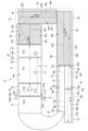
- FIG. 3 is a schematic diagram showing the state of the conveying path along the direction in which the conveying path of the supply device according to the embodiment extends.
- FIG. 4 is a schematic diagram showing an input conveyor, a first transport section, and the like of the supply device according to the embodiment.
- FIG. 5 is a block diagram showing the control system of the supply device according to the embodiment.
- FIG. 6 is a diagram illustrating an example of a captured image according to the embodiment;
- FIG. 7 is a diagram illustrating an operation example in which the supply device according to the embodiment calculates an area ratio;
- FIG. 8 is a diagram illustrating an operation example of the supply device according to the embodiment;
- FIG. 9 is a diagram illustrating an operation example of the supply device according to the embodiment;
- FIG. 10 is a flow chart showing
- the supply device 10 separates (separates) multi-layer packages, and supplies articles (process objects) at predetermined time intervals (predetermined pitch) to a sorting device that sorts by destination in, for example, a physical distribution system.
- the supply device 10 is, for example, a part of a manufacturing line, separates (separates) a large number of the same or different parts (processing objects), and feeds the parts to the succeeding device at predetermined time intervals (predetermined pitch). (object to be processed) may be supplied.
- FIG. 1 A supply device 10 according to an embodiment will be described with reference to FIGS. 1 to 4.
- FIG. 1 A supply device 10 according to an embodiment will be described with reference to FIGS. 1 to 4.
- FIG. 1 is a schematic perspective view showing the operating state of the supply device 10.
- FIG. FIG. 2 is a schematic view of the supply device 10 shown in FIG. 1 viewed from above.
- An XYZ orthogonal coordinate system is defined for the supply device 10 in FIG.
- FIG. 3 shows a state viewed from the inside (the other direction) to the outside (one direction) of the end portion in the width direction orthogonal to the extending direction of the conveying path.
- FIG. 3 assumes that the extending direction D (D10, D11, D12, D21, D22, D23, D31, D32) of the series of conveying paths of the supply device 10 shown in FIG. 2 is straight.
- 2 is a schematic diagram showing the inclination state and height difference of the conveying path along the extension direction D of FIG.
- FIG. 4 is a schematic diagram showing the positional relationship among the input conveyor 12, the first conveying section 14, the photographing means 101, and the like.
- the supply device 10 includes an input conveyor 12 to which a plurality of processing objects S are input, a first transport section 14, a second transport section 16, and a third transport section 18.
- the input conveyor 12 is a conveyor for inputting the processing objects S to the first transport section 14 .
- the input conveyor 12 loads processing objects S input by a robot, an operator, or a curved conveyor 92 .
- the input conveyor 12 transports the loaded processing objects S and inputs them from the downstream end of the input conveyor 12 to the upstream end of the first transport path 14a.
- the end on the upstream side of the conveying path itself is defined as the upstream end, and the end on the downstream side is defined as the downstream end.
- the first transport section 14 has a first transport path 14a that transports the processing target S from the upstream side to the downstream side along the first transport direction C1 (C10, C11, C12).
- extending directions D10, D11, and D12 of the first conveying unit 14 are apparently straight along the X-axis direction as a whole.
- D12 are tilted with respect to the X and Z axes along the ZX plane.
- the extending directions D11 and D12 are inclined with respect to the horizontal plane (ground).
- the second conveying section 16 is arranged downstream of the first conveying path 14a of the first conveying section 14, and has a second conveying path 16a that is bent in a U shape (including a J shape), for example.
- the second conveying path 16a of the second conveying section 16 conveys the processing object S from the upstream side to the downstream side along the second conveying directions C21, C22, and C23.
- the third transport section 18 is arranged downstream of the second transport path 16a and has a third transport path 18a that transports the processing object S from the upstream side to the downstream side along the third transport direction C32.
- the third conveying portion 18 is straight along the X-axis direction.
- a sorting device or the like is arranged on the downstream side of the third conveying section 18 .
- the first conveying section 14 and the third conveying section 18 are spaced apart in the Y-axis direction. Therefore, the first conveying section 14 and the third conveying section 18 face each other across a space.
- the horizontal component of the first transport path 14a in the first transport direction C1 and the horizontal component of the third transport path 18a in the third transport direction C32 are straight.
- the horizontal component of the first transport path 14a in the first transport direction C1 and the horizontal component of the third transport path 18a in the third transport direction C32 are parallel (including substantially parallel) to each other and directed in opposite directions.
- the first transport section 14 includes a first conveyor 22 (receiving conveyor) adjacent to the downstream side of the input conveyor 12 along the X axis, and a second conveyor disposed downstream of the first conveyor 22 along the X axis. 24.
- the first conveyor 22 receives the processing object S that is input by the input conveyor 12 .
- the first conveyor 22 has a horizontal conveying path 22a on a horizontal plane (ground), for example, by an endless belt.
- the second conveyor section 24 has a first inclined conveyor 32 having a conveying path 32a inclined with respect to the horizontal plane as a downward slope by, for example, an endless belt, and a conveying path 34a inclined with respect to the horizontal plane as an upward slope by, for example, an endless belt. and a second inclined conveyor 34 .
- the first inclined conveyor 32 is adjacent to the downstream side of the first conveyor 22 .
- the second inclined conveyor 34 is adjacent to the downstream side of the first inclined conveyor 32 .
- the first inclined conveyor 32 is inclined downward along the first conveying direction C1 due to the downward slope.
- the second inclined conveyor 34 is inclined upward along the first conveying direction C1 due to the upward slope.
- the transport speed V10 along the transport direction C10 of the transport path 22a of the first conveyor 22 is equal to or faster than the transport speed V11 along the transport direction C11 of the transport path 32a of the first inclined conveyor 32 of the second conveyor section 24.
- the conveying speed V12 along the conveying direction C12 of the conveying path 34a of the second inclined conveyor 34 of the second conveyor section 24 is the conveying speed V11 along the conveying direction C11 of the conveying path 32a of the first inclined conveyor 32 of the second conveyor section 24 is as fast as or faster than
- the inclination angle ⁇ 1 of the conveying path 32a of the first inclined conveyor 32 with respect to the horizontal plane shown in FIG. 3 is preferably, for example, about 10° to 40°.
- the inclination angle ⁇ 2 of the conveying path 34a of the second inclined conveyor 34 with respect to the horizontal plane is preferably, for example, about 10° to 40°.
- the upstream end of the conveying path 32a of the first inclined conveyor 32 is slightly lower. In this case, the processing object S is easily transferred between the transport path 22 a of the first conveyor 22 and the transport path 32 a of the first inclined conveyor 32 .
- a first fall sign detection sensor 102a and a second fall sign detection sensor 102b are formed at the upstream end of the input conveyor 12.
- the first drop sign detection sensor 102a detects the processing object S about to fall from the input conveyor 12 to the transport path 22a. That is, the first fall sign detection sensor 102a detects a sign that the processing object S will fall (immediately before it falls).
- the first fall sign detection sensor 102 a detects the processing object S downstream of the downstream end of the input conveyor 12 . That is, the first drop sign detection sensor 102 a detects the processing object S protruding from the downstream end of the input conveyor 12 .
- the first fall sign detection sensor 102a outputs a first detection result to the processor 301 as a detection result.
- the first fall sign detection sensor 102a is composed of a light source that emits light such as infrared light and a detection unit that detects the light from the light source.
- the first fall sign detection sensor 102a detects the processing object S when the light from the light source to the detection unit is blocked.
- the second drop sign detection sensor 102b similarly detects the processing object S about to drop from the input conveyor 12 onto the transport path 22a. That is, the second fall sign detection sensor 102b detects a sign that the processing object S will fall (immediately before it falls). The second fall sign detection sensor 102b detects the processing object S upstream from the position where the first fall sign detection sensor 102a detects the processing object S. Here, the second drop sign detection sensor 102 b detects the processing object S present at the downstream end of the input conveyor 12 . The second fall sign detection sensor 102b outputs a second detection result to the processor 301 as a detection result.
- the configuration of the second fall omen detection sensor 102b is the same as that of the first fall omen detection sensor 102a, so a description thereof will be omitted.
- photographing means 101 is formed above the first conveyor 22 .
- the photographing means 101 is installed so as to photograph the downward direction. That is, the photographing means 101 photographs the first conveyor 22 from above.
- the photographing means 101 is composed of lighting, a camera, and the like.
- the photographing means 101 photographs the photographing area 101A on the first conveyor 22 .
- the second transport section 16 includes a first offset conveyor 42, a second offset conveyor 44, and a third offset conveyor 42, which are adjacent to the downstream side of the first transport section 14 along the X-axis.
- a conveyor 46 In the second conveying section 16, the first offset conveyor 42, the second offset conveyor 44, and the third offset conveyor 46 are connected with different extending directions D21, D22, D23 and conveying directions C21, C22, C23.
- Extending directions D21, D22 and D23 of the first offset conveyor 42, the second offset conveyor 44 and the third offset conveyor 46 of the second conveying section 16 are U-shaped as a whole.
- the first offset conveyor 42, the second offset conveyor 44, and the third offset conveyor 46 may be arranged adjacent to each other, and need not be integrated as one conveyor.
- the first one-sided conveyor 42 of the second conveying section 16 is arranged downstream of the first conveying section 14 along the first conveying direction C1.
- the second offset conveyor 44 is installed downstream of the first offset conveyor 42 along a direction crossing the first offset conveyor 42 .
- the third offset conveyor 46 is installed downstream of the second offset conveyor 44 along a direction crossing the second offset conveyor 44 .
- the first offset conveyor 42 extends along the extending direction D21.
- the extending direction D21 of the first offset conveyor 42 substantially coincides with the horizontal component of the first conveying direction C1.
- the transport path 42a of the first offset conveyor 42 is parallel to the XY plane, for example.
- the conveying direction C21 of the processing object S along the conveying path 42a of the first offset conveyor 42 is deviated from the horizontal component of the first conveying direction C1.
- an oblique roller conveyor is used as the first offset conveyor 42.
- the conveying direction C21 is inclined at an inclination angle ⁇ a with respect to the extension direction D21 of the conveying path 42a of the first offset conveyor 42 .
- the first offset conveyor 42 moves the processing objects S placed on the transport path 42a of the first offset conveyor 42 in one direction of the width direction perpendicular to the extension direction D21, that is, one outer end portion. 42b.
- the transport path 42a of the first offset conveyor 42 moves in the extension direction D21 of the first offset conveyor 42 at a velocity of V21 ⁇ cos ⁇ a.
- the object S to be processed is moved along.
- the conveying speed V21 along the conveying direction C21 of the conveying path 42a of the first offset conveyor 42 is preferably higher than the conveying speed V12 along the conveying direction C12 of the conveying path 34a of the second inclined conveyor 34.
- first wall portion 52 is provided.
- the first wall portion 52 extends, for example, in parallel with the extension direction D21 of the conveying path 42a of the first offset conveyor 42 . Due to the presence of the first wall portion 52 , the object S to be processed is prevented from falling off from the end portion of the first offset conveyor 42 in one direction.
- the first wall portion 52 is an auxiliary conveying portion that actively or passively conveys the processing object S from the upstream side to the downstream side of the conveying path 42a of the first offset conveyor 42 along the first extending direction D21. 52a.
- the auxiliary conveying portion 52a of the first wall portion 52 faces the other inner end portion 42c in the width direction orthogonal to the extending direction D21 of the first offset conveyor 42. As shown in FIG.
- the auxiliary conveying portion 52a of the first wall portion 52 actively conveys the processing object S from the upstream side to the downstream side of the conveying path 42a of the first offset conveyor 42 along the first extending direction D21.
- a case will be described as an example.
- the auxiliary conveying section 52a has an endless belt similar to that used in belt conveyors, for example.
- the normal direction of the conveying surface 52b of the endless belt is, for example, horizontal and faces the inner side (the other direction) in the width direction.
- the conveying surface 52b of the endless belt of the auxiliary conveying portion 52a moves the processing object S from the upstream side to the downstream side in parallel with the first extending direction D21 at a speed of V21 ⁇ cos ⁇ a, for example.
- a step H of about 10 cm, for example, is preferably formed between the downstream end of the second inclined conveyor 34 and the upstream end of the first offset conveyor 42 .
- the second offset conveyor 44 extends, for example, in a direction along the Y-axis perpendicular to the extension direction D21 (direction along the X-axis) of the first offset conveyor 42 .
- the transport path 44a of the second offset conveyor 44 is parallel to the XY plane, for example.
- An oblique roller conveyor for example, is used as the second offset conveyor 44 .
- the conveying direction C22 of the second offset conveyor 44 is inclined at an inclination angle ⁇ b with respect to the extending direction D22 of the second offset conveyor 44 . It is preferable that the inclination angle ⁇ b is, for example, about 10° to 40°. For this reason, the second offset conveyor 44 moves the processing objects S placed on the transport path 44a of the second offset conveyor 44 in one direction of the width direction perpendicular to the extension direction D22, that is, one outer edge. 44b.
- the conveying path 44a of the second offset conveyor 44 moves toward the second offset conveyor 44 at a speed of V22 ⁇ cos ⁇ b ( ⁇ V21 ⁇ cos ⁇ a). to move the processing object S along the extension direction D22.
- the conveying speed V22 along the conveying direction C22 of the conveying path 44a of the second offset conveyor 44 is preferably higher than the conveying speed V21 along the conveying direction C21 of the conveying path 42a of the first offset conveyor 42.
- the second wall portion 54 extends, for example, in parallel with the extending direction D22 of the conveying path 44a of the second offset conveyor 44 . Due to the presence of the second wall portion 54 , the object S to be processed is prevented from falling off the second one-sided conveyor 44 .
- the second wall portion 54 is an auxiliary conveying portion that actively or passively conveys the processing target S from the upstream side to the downstream side of the conveying path 44a of the second offset conveyor 44 along the second extending direction D22. 54a.
- the auxiliary conveying portion 54a of the second wall portion 54 faces the other inner end portion 44c in the width direction orthogonal to the extending direction D22 of the second side conveyor 44. As shown in FIG.
- the auxiliary conveying portion 54a of the second wall portion 54 actively conveys the processing object S from the upstream side to the downstream side of the conveying path 44a of the second offset conveyor 44 along the second extending direction D22.
- a case will be described as an example.
- the auxiliary transport section 54a is formed, for example, in the same manner as the auxiliary transport section 52a. Therefore, the conveying surface 54b of the endless belt of the auxiliary conveying portion 54a operates to move the processing object S from the upstream side to the downstream side at a speed of, for example, V22 ⁇ cos ⁇ b in parallel with the second extending direction D22.
- the third offset conveyor 46 is adjacent to the downstream side of the second offset conveyor 44 along the Y-axis.
- the third offset conveyor 46 extends in a direction orthogonal to the extension direction D22 of the second offset conveyor 44, for example.
- the transport path 46a of the third offset conveyor 46 is parallel to the XY plane, for example.
- As the third offset conveyor 46 for example, an oblique roller conveyor is used.
- the conveying direction C23 of the third offset conveyor 46 is inclined at an inclination angle ⁇ c with respect to the extension direction D23 of the third offset conveyor 46 . It is preferable that the inclination angle ⁇ c is, for example, about 10° to 40°. For this reason, the third offset conveyor 46 moves the processing objects S placed on the conveying path 46a of the third offset conveyor 46 in one direction in the width direction perpendicular to the extension direction D23, that is, at one outer edge. 46b.
- the conveying path 46a of the third offset conveyor 46 moves toward the third offset conveyor 46 at a speed of V23 ⁇ cos ⁇ c ( ⁇ V22 ⁇ cos ⁇ b). to move the processing object S along the extension direction D23.
- the conveying speed V23 along the conveying direction C23 of the conveying path 46a of the third offset conveyor 46 is preferably higher than the conveying speed V22 along the conveying direction C22 of the conveying path 44a of the second offset conveyor 44.
- the third wall portion 56 extends parallel to the extension direction D23 of the conveying path 46a of the third offset conveyor 46, for example. The existence of the third wall portion 56 prevents the object S to be processed from falling off the third one-sided conveyor 46 .
- the third wall portion 56 is an auxiliary conveying portion that actively or passively conveys the processing object S from the upstream side to the downstream side of the conveying path 46a of the third offset conveyor 46 along the third extending direction D23. 56a.
- the auxiliary conveying portion 56a of the third wall portion 56 faces the other inner end portion 46c in the width direction orthogonal to the extending direction D23 of the third bias conveyor 46. As shown in FIG.
- the auxiliary conveying portion 56a of the third wall portion 56 actively conveys the processing object S from the upstream side to the downstream side of the conveying path 46a of the third offset conveyor 46 along the third extending direction D23.
- a case will be described as an example.
- the auxiliary conveying portion 56a is formed, for example, in the same manner as the auxiliary conveying portions 52a and 54a. Therefore, the conveying surface 56b of the endless belt of the auxiliary conveying portion 56a moves the processing object S from the upstream side to the downstream side in parallel with the second extending direction D23 at a speed of V23 ⁇ cos ⁇ c, for example.
- the third transport section 18 has a narrow conveyor 62 (downstream conveyor), a speed control conveyor 64 and a collection section 66 .
- a camera (sensor) (not shown) for recognizing the speed of the conveying path 62a of the narrow conveyor 62 and the distance between the objects to be processed S before and after the conveying path 62a is arranged in the third conveying unit 18, for example. ing.
- the narrow conveyor 62 is adjacent to the downstream side of the third offset conveyor 46 along the X-axis.
- the upstream end of the narrow conveyor 62 is formed to have a smaller width than the width in the width direction perpendicular to the extension direction D23 of the downstream end of the third offset conveyor 46 .
- the width of the narrow conveyor 62 is set according to the size of the processing object S, for example.
- the narrow conveyor 62 has a width that does not allow a plurality of processing objects S of appropriate size to be arranged in the width direction.
- the narrow conveyor 62 has a horizontal conveying path 62a on a horizontal plane (ground), for example, by an endless belt.
- the upstream end of the conveying path 62a of the narrow conveyor 62 is arranged at a position adjacent to the downstream end in one width direction of the conveying path 46a of the third offset conveyor 46 .
- the conveying direction C31 of the narrow conveyor 62 is parallel to the extending direction D31 of the narrow conveyor 62 .
- the conveying speed V31 along the conveying direction C31 of the conveying path 62a of the narrow conveyor 62 is preferably higher than the conveying speed V23 along the conveying direction C23 of the conveying path 46a of the third offset conveyor 46.
- a wall for preventing the object to be processed S from falling off from one direction of the narrow conveyor 62 is provided at the outer end portion 62b in one direction in the width direction perpendicular to the extending direction D31 (conveying direction C31) of the narrow conveyor 62.
- a fourth wall portion 68 is provided. The fourth wall portion 68 extends parallel to the extending direction D31 of the conveying path 62a of the narrow conveyor 62, for example. The existence of the fourth wall portion 68 prevents the object to be processed S from falling off the narrow conveyor 62 .
- the outer end 62b of the narrow conveyor 62 and the outer end 46b of the third offset conveyor 46 are preferably aligned along the X-axis.
- the fourth wall portion 68 has an auxiliary conveying portion 68a that actively or passively conveys the processing object S from the upstream side to the downstream side of the conveying path 62a of the narrow conveyor 62 along the extending direction D31.
- the auxiliary conveying portion 68a of the fourth wall portion 68 faces the other inner end portion 62c in the width direction orthogonal to the extending direction D23 of the narrow conveyor 62. As shown in FIG.
- the auxiliary conveying portion 68a of the fourth wall portion 68 actively conveys the processing object S from the upstream side to the downstream side of the conveying path 62a of the narrow conveyor 62 along the fourth extension direction D31.
- a case will be described as an example.
- the auxiliary transport portion 68a is formed in the same manner as the auxiliary transport portions 52a, 54a, and 56a, for example. Therefore, the conveying surface 68b of the endless belt of the auxiliary conveying portion 68a moves the processing object S from the upstream side to the downstream side in parallel with the extending direction D31, for example, at a speed V31.
- the horizontal component of the first transport path 14a in the first transport direction C1 and the horizontal component of the third transport path 18a in the third transport direction C32 are straight.
- an adjusting portion passage detection sensor 103 is formed at the downstream end of the narrow conveyor 62.
- the adjustment unit passage detection sensor 103 detects the processing object S that has passed through the narrow conveyor 62 and is thrown into the speed control conveyor 64 .
- the configuration of the adjustment unit passage detection sensor 103 is the same as that of the first fall sign detection sensor 102a, so the description is omitted.
- the speed control conveyor 64 is adjacent to the downstream side of the narrow conveyor 62 along the X-axis.
- the conveying path 64a of the speed-regulating conveyor 64 appropriately accelerates or decelerates the conveying speed of the conveying path 62a of the narrow conveyor 62 so that the processing objects S placed on the conveying path 64a are separated from each other by a predetermined pitch. be done.
- the upstream end of the speed control conveyor 64 is formed to have substantially the same width as the width in the width direction perpendicular to the extension direction D31 of the downstream end of the narrow conveyor 62 .
- a conveying path 64a of the speed control conveyor 64 is horizontal to a horizontal plane (ground), for example, by an endless belt.
- the conveying direction C32 of the speed controlling conveyor 64 is parallel to the extending direction D32 of the speed controlling conveyor 64 .
- the conveying speed V32 along the conveying direction C32 of the conveying path 64a of the speed control conveyor 64 is controlled so that the processing objects S arranged in a line are spaced apart at a predetermined pitch. Therefore, the conveying speed V32 along the conveying direction C32 of the conveying path 64a of the speed control conveyor 64 can be increased and decelerated.
- a wall for preventing the object to be processed S from falling off from one direction of the speed control conveyor 64 is provided at an outer end portion 64b in one direction of the width direction perpendicular to the extending direction D32 (conveying direction C32) of the speed control conveyor 64.
- a fifth wall portion 70 is provided. The fifth wall portion 70 extends parallel to the extension direction D32 of the transport path 64a of the speed control conveyor 64, for example. The presence of the fifth wall portion 70 prevents the object to be processed S from falling off the speed control conveyor 64 .
- the outer end 64b of the speed control conveyor 64 and the outer end 62b of the narrow conveyor 62 are preferably aligned along the X-axis.
- the fifth wall portion 70 has an auxiliary conveying portion 70a that actively or passively conveys the processing object S from the upstream side to the downstream side of the conveying path 64a of the speed control conveyor 64 along the extending direction D32.
- the auxiliary conveying portion 70a of the fifth wall portion 70 faces the other inner end portion 64c in the width direction orthogonal to the extending direction D32 of the speed control conveyor 64. As shown in FIG.
- the auxiliary transport section 70a may be formed as a transport surface that actively transports the processing target S, for example, like the transport surfaces 52b, 54b, 56b, and 68b of the auxiliary transport sections 52a, 54a, 56a, and 68a.
- the auxiliary transport section 70a has a plurality of rollers 70b that passively rotate when the processing target S contacts.
- the rollers 70b in FIG. 3 are arranged, for example, in a grid pattern or in a row.
- Each of the rollers 70b is formed in a spherical shape and is freely rotatable at that position.
- the rollers 70b may be formed to rotate around axes parallel to the Z-axis, like rollers (wheels) of a roller conveyor.
- the collecting section 66 is adjacent to the downstream end along the X-axis of the conveying path 46a of the third one-sided conveyor 46 of the second conveying section 16, and is adjacent to the narrow conveyer 62 in the other width direction (inner side).
- the recovery section 66 has an inclined surface 72 and a guide 74 .
- the inclined surface 72 is formed as a flat surface or a curved surface.
- the inclined surface 72 is higher at a position closer to the narrow conveyor 62 (first end 72a), and closer to the other position (second end 72b) in the width direction perpendicular to the horizontal component of the transport direction C1 of the first transport section 14. ).
- the inclined surface 72 is higher at a position (third end portion 72c) closer to the downstream end of the transport path 46a of the third offset conveyor 46, and is separated from the downstream end of the transport path 46a of the third offset conveyor 46 along the X-axis direction.
- the position (the fourth end 72d) is lower.
- the processing object S placed on the inclined surface 72 slides toward the fourth end 72d of the inclined surface 72 due to its own weight.
- the first end 72a of the inclined surface 72 on the side of the narrow conveyor 62 may be continuous with the downstream end of the conveying path 62a of the narrow conveyor 62, and may be connected to the downstream end of the conveying path 62a of the narrow conveyor 62 with a step. It may be located on the lower side.
- the guide 74 is formed in a plate shape.
- the guide 74 is fixed to the second end 72b of the inclined surface 72. As shown in FIG.
- the guide 74 extends along the X-axis direction.
- the guide 74 is formed so as to protrude upward from a second end portion 72b of the inclined surface 72 (an end portion near the other in the width direction perpendicular to the horizontal component of the conveying direction C1 of the first conveying portion 14).
- the supply device 10 is adjacent to the collection unit 66 that collects the processing objects S in the third transport unit 18, and feeds the processing objects S collected by the collection unit 66 to the feeding conveyor 12. It has the 4th conveyance part 20 conveyed towards.
- the fourth transport section 20 has a curved conveyor 92, for example.
- the curved conveyor 92 is provided between the fourth end portion 72 d of the inclined surface 72 of the collection section 66 and the input conveyor 12 .
- the upstream end of the conveying path 92 a of the curved conveyor 92 is adjacent to the fourth end 72 d of the inclined surface 72 .
- the downstream end of the conveying path 92 a of the curved conveyor 92 is adjacent to the input conveyor 12 .
- the length along the extension directions D21, D22, and D23 of the first offset conveyor 42, the second offset conveyor 44, and the third offset conveyor 46 of the second conveying unit 16 is perpendicular to the extension directions D21, D22, and D23.
- the widths, angles ⁇ a, ⁇ b, and ⁇ c are such that, for example, the processing object S at the inner end portion 42c of the downstream end of the conveying path 42a of the first offset conveyor 42 is located between the first offset conveyor 42 and the second offset conveyor 42, as will be described later. It is set so as to come into contact with the outer end portion 46 b of the third offset conveyor 46 after passing through the conveyor 44 and the third offset conveyor 46 .
- FIG. 5 is a block diagram showing a configuration example of a control system of the supply device 10.
- the supply device 10 includes a processor 301, a memory 302, an image capturing means 101, a first drop sign detection sensor 102a, a second drop sign detection sensor 102b, an input conveyor 12, an adjusting unit passing detection sensor 103, and an adjusting unit passage detection sensor 103.
- a high-speed conveyor 64 and the like are provided.
- the processor 301, the memory 302, the photographing means 101, the first fall sign detection sensor 102a, the second fall sign detection sensor 102b, the input conveyor 12, the adjusting section passage detection sensor 103, and the speed control conveyor 64 are connected by an interface, a data bus, or the like. connect to each other through
- the processor 301 controls the operation of the supply device 10 as a whole.
- the processor 301 is composed of a CPU and the like.
- the processor 301 may be composed of an ASIC (Application Specific Integrated Circuit) or the like.
- the processor 301 may be composed of an FPGA (Field Programmable Gate Array) or the like.
- Memory 302 stores various data.
- memory 302 functions as ROM, RAM and NVM.
- the memory 302 stores control programs, control data, and the like.
- the control program and control data are preinstalled according to the specifications of the supply device 10 .
- the control program is a program that supports functions implemented by the supply device 10 .
- the memory 302 also temporarily stores data being processed by the processor 301 .
- the memory 302 may also store data necessary for executing the application program, execution results of the application program, and the like.
- the memory 302 the photographing means 101, the first drop sign detection sensor 102a, the second drop sign detection sensor 102b, the input conveyor 12, the adjustment unit passage detection sensor 103, and the speed control conveyor 64 are as described above.
- the functions realized by the supply device 10 are realized by the processor 301 executing a program stored in the memory 302 or the like.
- the transport speed along the first transport direction C1 (C10, C11, C12) of the first transport unit 14 is assumed to match the moving speed of the processing object S in contact with the first transport unit 14.
- the conveying speed of the second conveying section 16 along the second conveying directions C21, C22, and C23 is such that the processing target S does not contact the first wall section 52, the second wall section 54, and the third wall section 56.
- the moving speed of the processing object S in contact with the second conveying unit 16 is assumed to match.
- the conveying speed along the third conveying directions C31 and C32 of the third conveying section 18 is set so that the processing target S does not contact the fourth wall section 68 and the fifth wall section 70 and is in contact with the third conveying section 18. It is assumed that the transport speed of the object S is the same.
- the tipper tilts and the object S to be processed is thrown into the feeding conveyor 12 .
- a robot or an operator may input the processing objects S to the input conveyor 12 .
- the objects S to be processed which may be in a multi-layered bulk state on the input conveyor 12, are sequentially disposed at the upstream end of the transport path 22a of the first conveyor 22 of the first transport unit 14 due to, for example, the inclination of the floor surface of the input conveyor 12. move towards
- the first conveyor 22 of the first transport unit 14 takes out the processing object S that has come into contact with the transport path 22a by the transport operation of the transport path 22a, and separates the plurality of processing objects S while moving in the transport direction C10. Let it fall apart.
- the processing object S in contact with the conveying path 22a of the first conveyor 22 is conveyed from the upstream side toward the downstream side.
- the other processing object S superimposed on the upper side of the processing object S moves to the lower side of the processing object S according to the frictional force with the lower processing object S. It slides on the object S to be processed. For this reason, a part of the multi-layer processing object S is broken. In this way, for example, a part of the multi-layered processing object S is separated and separated.
- the processing object S is transferred from the conveying path 22 a of the first conveyor 22 to the conveying path 32 a of the first inclined conveyor 32 of the second conveyor section 24 .
- the conveying path 32a of the first inclined conveyor 32 is inclined downward.
- a horizontal tilting component parallel to the upper surface of the processing object S acts on the processing object S placed on the upper side of the processing object S, which is in contact with the conveying path 32a of the first inclined conveyor 32. .
- other processing objects S superimposed on the upper side of the processing object S in contact with the conveying path 32a contact the conveying path 32a more than when the conveying path 22a of the first conveyor 22 is horizontal. It is slippery with respect to the processed object S.
- the transport speed V11 of the transport path 32a of the first inclined conveyor 32 is lower than the transport speed V10 of the transport path 22a of the first conveyor 22. Therefore, due to the difference in conveying speed between the horizontal conveying path 22a of the first conveyor 22 and the conveying path 32a of the first inclined conveyor 32, the object to be processed S in contact with the conveying path 32a is braked, and the conveying path is stopped.
- the upper processing object S in contact with the processing object S in contact with the 32a slides against the processing object S in contact with the transport path 32a due to the law of inertia, and the multilayer processing object S is collapsed.
- the multi-layered objects S to be processed are collapsed on the first inclined conveyor 32 due to the inclined surface that is the downhill conveying path 32a and the law of inertia. For this reason, for example, a part of the multi-layered processing object S is separated and separated.
- the object S in contact with the conveying path 32a of the first inclined conveyor 32 rolls and becomes a plurality of layers such as two layers.
- the object S to be processed is destroyed.
- a part of the processing object S is transferred from the transport path 32a of the first inclined conveyor 32 of the second conveyor part 24 to the transport path 34a of the second inclined conveyor 34 of the second conveyor part 24, for example, in a state of multiple layers. .
- the conveying path 34a of the second inclined conveyor 34 is inclined as an upward slope. For this reason, other processing objects S superimposed on the upper side of the processing object S in contact with the conveying path 34a contact the conveying path 34a more than when the conveying path 22a of the first conveyor 22 is horizontal. It is slippery with respect to the processed object S.
- the transport speed V12 of the transport path 34a of the second inclined conveyor 34 is higher than the transport speed V11 of the transport path 32a of the first inclined conveyor 32. Therefore, due to the difference in conveying speed between the conveying path 32a of the first inclined conveyor 32 and the conveying path 34a of the second inclined conveyor 34, the object to be processed S in contact with the conveying path 34a is accelerated and contacts the conveying path 34a.
- the processing object S on the upper side of the processing object S slides against the processing object S in contact with the conveying path 34a due to the law of inertia, and the multi-layer processing object S is collapsed.
- the multi-layered objects S to be processed are further collapsed on the second inclined conveyor 34 due to the inclined surface that is the uphill conveying path 34a and the law of inertia. For this reason, for example, a part of the multi-layered processing object S is separated and separated.
- first conveyor 22 and the second conveyor section 24 break down the multi-layered processing objects S and separate them one by one.
- These multilayer objects S to be processed may be the same kind of parts or different kinds of parts.
- the processing object S is transferred from the second inclined conveyor 34 to the first one-sided conveyor 42 . Due to the step H between the second inclined conveyor 34 and the first offset conveyor 42 , the object S to be processed moves greatly when transferred from the second inclined conveyor 34 to the first offset conveyor 42 . At this time, the processing object S is separated by pulling the processing object so as to take it out along the conveying direction C21 by the first offset conveyor 42 on the downstream side of the second inclined conveyor 34 .
- FIG. 3 shows an example in which a step H is provided between the second inclined conveyor 34 and the first offset conveyor 42 .
- a conveyor having a horizontal transport path is arranged between the second inclined conveyor 34 and the first offset conveyor 42, and there is a step H between the conveyor having the horizontal transport path and the first offset conveyor 42. good too.
- the objects S separated one by one are inclined with respect to the extension direction D21 of the first offset conveyor 42 on the conveying path 42a of the first offset conveyor 42 as they go from the upstream side to the downstream side. It moves in the transport direction C21. Therefore, a plurality of processing objects S are shifted toward the first wall portion 52 on the conveying path 42 a of the first shift conveyor 42 . Therefore, the distance in the width direction of the plurality of processing objects S is gradually narrowed from the upstream side to the downstream side. A portion of the processing target S abuts against the first wall portion 52 between the upstream end and the downstream end of the conveying path 42 a of the first one-sided conveyor 42 .
- the object S to be processed which is brought into contact with the first wall portion 52 on the transport path 42a of the first offset conveyor 42, moves in the extending direction D21 of the transport path 42a at a speed of V21 ⁇ cos ⁇ a.
- the processing object S moves along the first wall portion 52 and is transferred from the transport path 42 a of the first offset conveyor 42 to the transport path 44 a of the second offset conveyor 44 . Therefore, the auxiliary conveying portion 52a of the first wall portion 52 prevents the first wall portion 52 from interfering with the movement of the processing object S when the processing object S comes into contact with the first wall portion 52. do.
- the objects S to be processed move along the conveying path 44a of the second conveyor 44 in the conveying direction C22 that is inclined with respect to the extension direction D22 of the second conveyor 44 as it goes from the upstream side to the downstream side.
- the conveying direction of the processing target S is changed from the extending direction D21 or the conveying direction C21 to the conveying direction C22. Therefore, a plurality of objects S to be processed are shifted toward the second wall portion 54 on the conveying path 44 a of the second shift conveyor 44 . Therefore, the distance in the width direction of the plurality of processing objects S is gradually narrowed.
- a portion of the processing target S abuts against the second wall portion 54 between the upstream end and the downstream end of the conveying path 44 a of the second offset conveyor 44 . For this reason, the plurality of processing objects S are closer to being in one row.
- the object S to be processed which is in contact with the second wall portion 54 on the conveying path 44a of the second offset conveyor 44, moves in the extending direction D22 of the conveying path 44a at a speed of V22 ⁇ cos ⁇ b.
- the processing object S moves along the second wall portion 54 and is transferred from the transport path 44 a of the second offset conveyor 44 to the transport path 46 a of the third offset conveyor 46 . Therefore, the auxiliary conveying portion 54a of the second wall portion 54 prevents the second wall portion 54 from interfering with the movement of the processing object S when the processing object S comes into contact with the second wall portion 54. do.
- the processing target S moves on the conveying path 46a of the third one-sided conveyor 46 in the conveying direction C23 inclined with respect to the extending direction D23 of the third one-sided conveyor 46 as it goes from the upstream side to the downstream side.
- the conveying direction of the object S is changed from the direction along the extension direction D22 or the direction along the conveying direction C22 to the direction along the conveying direction C23. Therefore, a plurality of objects S to be processed are shifted toward the third wall portion 56 on the conveying path 46 a of the third shift conveyor 46 . Therefore, the distance in the width direction of the plurality of processing objects S is gradually narrowed.
- a portion of the processing target S abuts against the third wall portion 56 between the upstream end and the downstream end of the conveying path 46 a of the third one-sided conveyor 46 .
- a plurality of processing objects S are arranged in one row.
- the plurality of processing objects S transported along the center of the width direction of the first transport path 14 a of the first transport section 14 are transported along the transport path 42 a of the first offset conveyor 42 and the transport of the second offset conveyor 44 .
- the side-by-side state perpendicular to the extension directions D21, D22, and D23 is gradually eliminated.
- the plurality of objects S to be processed are arranged in a row on the conveying path 46a of the third one-sided conveyor 46, for example.
- the second conveying unit 16 shifts the plurality of processing objects S as a whole to one direction in the width direction orthogonal to the extending directions D21, D22, and D23 of the U-shaped second conveying path 16a. Align them in a row.
- the object S to be processed which is brought into contact with the third wall portion 56 on the conveying path 46a of the third offset conveyor 46, moves in the extending direction D23 of the conveying path 46a at a speed of V23 ⁇ cos ⁇ c.
- the processing object S moves along the third wall portion 56 and is transferred from the conveying path 46 a of the third conveyor 46 to the conveying path 62 a of the narrow conveyor 62 . Therefore, the auxiliary conveying portion 56a of the third wall portion 56 prevents the third wall portion 56 from interfering with the movement of the processing object S when the processing object S comes into contact with the third wall portion 56. do.
- the transport speed V31 of the transport path 62a of the narrow conveyor 62 is faster than V23 ⁇ cos ⁇ c. Therefore, when the objects S to be processed are transferred from the conveying path 46a of the third conveyor 46 to the conveying path 62a of the narrow conveyor 62, the conveying path 62a of the narrow conveyor 62 is arranged in a row. widen the pitch.
- the object to be processed S which is in contact with the fourth wall portion 68 on the conveying path 62a of the narrow conveyor 62, moves along the predetermined conveying direction C31 (extending direction D31) of the conveying path 62a at a speed of V31. do.
- the processing object S moves along the fourth wall portion 68 and is transferred from the transport path 62 a of the narrow conveyor 62 to the transport path 62 a of the narrow conveyor 62 . Therefore, the auxiliary conveying portion 68a of the fourth wall portion 68 prevents the fourth wall portion 68 from interfering with the movement of the processing object S when the processing object S comes into contact with the fourth wall portion 68. do.
- the conveying speed V32 of the conveying path 64a of the speed control conveyor 64 of the third conveying section 18 is appropriately controlled based on the information on the preceding and succeeding processing objects S above. That is, the acceleration and deceleration of the conveying speed V32 along the predetermined conveying direction C32 (extending direction D32) of the conveying path 64a of the speed-regulating conveyor 64 of the third conveying unit 18 are controlled.
- the processing objects S arranged in a row are spaced apart at a predetermined pitch.
- the objects S to be processed which are spaced apart at a predetermined pitch and arranged in a line, are fed to a device on the downstream side of the third conveying section 18 .
- the roller 70b of the auxiliary conveying section 70a rotates at that position, and the speed control conveyor of the third conveying section 18 moves parallel to the extending direction D32.
- the processing object S is moved from the upstream side to the downstream side at the speed V32 of the conveying path 64a of 64. Therefore, the auxiliary conveying part 70a of the fifth wall part 70 prevents the friction between the fifth wall part 70 and the object S to interfere with the movement of the object S to be treated.
- the plurality of objects S to be processed are not arranged in a line, and in the transport path 46a of the third offset conveyor 46, the width orthogonal to the extension direction D23 of the third offset conveyor 46 may be aligned in the direction Among the processing objects S not arranged in one line on the conveying path 46 a of the third offset conveyor 46 , the processing objects S that are separated from the third wall portion 56 in the width direction From the downstream end of 46 a , the sheet is not conveyed to the conveying path 62 a of the narrow conveyor 62 but transferred to the inclined surface 72 of the fourth conveying section 20 . Therefore, the object S to be processed reaches the fourth end 72 d of the inclined surface 72 while sliding near the boundary between the inclined surface 72 and the guide 74 .
- the processing object S that has reached the fourth end 72 d of the inclined surface 72 is conveyed to the input conveyor 12 by the curved conveyor 92 .
- the recovery unit 66 and the fourth transport unit 20 direct the processing objects S, which have failed to be shifted in one direction in the second transport unit 16, to the first transport unit 14 among the processing objects S. transport.
- the collecting unit 66 can collect a part of the processing objects S that have been shifted in one direction in the second transport unit 16 . Therefore, the processing objects S collected by the collecting unit 66 and conveyed from the fourth conveying unit 20 to the input conveyor 12 are transferred again from the input conveyor 12 to the first transport unit 14, the second transport unit 16, and the third transport unit. After passing through the section 18 , they are arranged at a predetermined pitch with respect to the other processing objects S, and are fed to a device on the downstream side of the third conveying section 18 .
- the first transport section 14 of the supply device 10 is used as a separate stage for separating the plurality of randomly stacked processing objects S one by one.
- the second conveying unit 16 is used as an arranging stage for aligning the objects S separated one by one in a row.
- the third conveying unit 18 is used as an adjusting stage that separates the processing objects S arranged in a line at a predetermined pitch. Then, the supply device 10 according to the present embodiment can transport a plurality of processing objects S to the first transporting unit 14, the second transporting unit 16, and the third transporting unit 18 in this order, and transfer them to another device. can.
- the processor 301 of the feeding device 10 has a function of photographing the first conveyor 22 using the photographing means 101 .
- the processor 301 When the processor 301 starts the operation of separating the object S to be processed, it causes the photographing means 101 to start photographing. When the photographing unit 101 is caused to start photographing, the processor 301 acquires a photographed image (captured image) from the photographing unit 101 . A processor 301 acquires a photographed image from the photographing means 101 in real time.
- FIG. 6 shows an example of a photographed image acquired by the processor 301.
- the captured image is an image of the first conveyor 22 captured from above.
- the photographed image includes the processing objects S loaded on the first conveyor 22 .
- the captured image may include input conveyor 12 (left end in FIG. 6) and first inclined conveyor 32 (right end in FIG. 6).
- the processor 301 also has a function of calculating the ratio (area ratio) occupied by the processing object S in the captured image.
- the processor 301 divides the captured image into a plurality of regions and calculates the area ratio for each region.
- FIG. 7 shows an operation example in which the processor 301 calculates the area ratio.
- the processor 301 sets the area ratio detection area 201 for which the area ratio is to be calculated in the captured image.
- the area ratio detection area 201 includes an area where the first conveyor 22 is captured.
- the processor 301 divides the area ratio detection area 201 into a plurality of areas (divided areas) in a grid pattern.
- the processor 301 divides the area ratio detection region 201 into six in the X-axis direction and four in the Y-axis direction.
- the processor 301 extracts areas (object area, article area) in which the processing object S appears in the area ratio detection area 201 according to a predetermined image processing algorithm. In the example shown in FIG. 7, the processor 301 extracts the hatched area as the object area.
- the processor 301 calculates the area of the object area overlapping each divided area. For example, processor 301 calculates the number of dots in the object area in each divided area.
- the processor 301 After calculating the area of the object region overlapping each divided region, the processor 301 divides the calculated area by the area of the divided region to calculate the area ratio in each divided region. For example, the processor 301 calculates the area ratio by dividing the number of dots in the object area overlapping each divided area by the number of dots in the divided area.
- the processor 301 acquires an area ratio group AR including area ratios in each divided region.
- the processor 301 also has a function of stopping the input conveyor 12 based on the area ratio group AR.
- FIG. 8 shows an operation example of stopping the input conveyor 12 by the processor 301 .
- the area ratio group AR is composed of area ratios AR1 to AR24 in each divided region.
- the area ratios AR1 to AR24 correspond to the divided regions in order in the X-axis direction and the Y-axis direction.
- the area ratios AR1 to AR4 correspond to the divided areas in order in the Y direction in the first row.
- the processor 301 sets areas 401 to 403 in areas where the first conveyor 22 is shown.
- An area 401 is an area in which the processing object S protruding from the input conveyor 12 is shown.
- a region 402 (dropping region) is a region where the processing object S falls from the input conveyor 12 . That is, the area 402 is an area to which the processing object S is supplied when the input conveyor 12 is driven.
- An area 403 (loading area) is an area in which the processing object group GS loaded on the first conveyor 22 is shown. That is, the area 403 is an area in which the processing object group GS supplied downstream by the first conveyor 22 is shown.
- the processor 301 determines whether to stop the input conveyor 12 based on the area ratio in the area 402 .
- the processor 301 acquires the area ratios of the divided regions in the region 402 (here, the area ratios AR5 to AR12). After obtaining the area ratio, the processor 301 calculates the average value of the obtained area ratios (partial average area ratio).
- the processor 301 determines whether the partial average area ratio is equal to or greater than a predetermined threshold (stop determination threshold). For example, the stop determination threshold is 30% to 70%.
- the processor 301 When determining that the partial average area ratio is equal to or greater than the stop determination threshold, the processor 301 stops the input conveyor 12 .
- the processor 301 when determining that the partial average area ratio is less than the stop determination threshold, the processor 301 keeps driving the input conveyor 12 . Also, when the input conveyor 12 is stopped, the processor 301 drives the input conveyor 12 .
- the processor 301 may determine whether to stop the input conveyor 12 based on the total area ratio of the divided areas in the area 402 .
- the processor 301 may also determine whether to stop the input conveyor 12 based on the area ratio of the divided areas in the other area.
- the processor 301 also has a function of estimating the time (downstream transport time T1) during which the processing object group GS is transported from the narrow conveyor 62 to the speed control conveyor 64 .
- FIG. 9 is a diagram for explaining the downstream transport time T1.
- FIG. 9 shows the state of the processing object group GS loaded by the narrow conveyor 62 and the speed control conveyor 64 at the time t, and the processing objects loaded by the narrow width conveyor 62 and the speed control conveyor 64 at the time t+downstream transportation time T1. and the state of the group GS.
- the processing object group GS is in a state of being separated by the first transport section 14, the second transport section 16, and the like.
- the first processing object S in the processing object group GS has reached the downstream end of the narrow conveyor 62 . That is, the narrow conveyor 62 starts conveying the processing object group GS to the speed control conveyor 64 at time t.
- the last processing object S of the processing object group GS is transported from the narrow conveyor 62 to the speed control conveyor 64. That is, at time t+downstream transport time T1, the transport of the processing object group GS to the speed control conveyor 64 is completed.
- the width between the upstream end of the last object to be processed S and the upstream end of the narrow conveyor 62 is a predetermined width (target pitch P). That is, at time t+downstream transfer time T1, a predetermined interval is formed between the last processing object S and the processing object S that follows.
- the downstream transport time T1 is the time for the separated processing object group GS to pass through the upstream end of the narrow conveyor 62 (here, the time for forming the target pitch is added). That is, the downstream transport time T1 is a value obtained by dividing the length of the separated processing object group GS (here, the length including the target pitch) by the transport speed of the narrow conveyor 62 .
- the processor 301 calculates the downstream transport time T1 based on the area ratio in the region 403.
- the processor 301 acquires the area ratios of the divided regions in the region 402 (here, the area ratios AR5 to AR24). After acquiring the area ratio, the processor 301 inputs the acquired area ratio to a model for estimating the downstream transport time T1 (transport time estimation model) to calculate the downstream transport time T1.
- a model for estimating the downstream transport time T1 transport time estimation model
- the transportation time estimation model is pre-stored in the memory 302 or the like.
- the transportation time estimation model is a multiple regression using the area ratio of the divided regions in the region 402 as an explanatory variable and the actual time when the processing object group GS is transported from the narrow conveyor 62 to the speed control conveyor 64 as an objective variable. is a model.
- a transportation time estimation model is generated based on pre-collected explanatory variables and objective variables.
- the transportation time estimation model may be a model obtained by machine learning such as a neural network.
- the configuration of the transportation time estimation model is not limited to a specific configuration.
- the processor 301 also has a function of predicting the time (falling waiting time T2) for the processing object group GS to fall from the input conveyor 12 to the first conveyor 22 when the input conveyor 12 is driven from a stopped state.
- the drop waiting time T2 is the average value of the area ratio group AR (or the area ratio of a part of the area 402 or 403, etc.) after the object to be processed S drops to the first conveyor 22 after the input conveyor 12 is driven. becomes equal to or greater than the drop determination threshold.
- the drop determination threshold is about 5% to 20%.
- the processor 301 acquires detection results from the first fall sign detection sensor 102a and the second fall sign detection sensor 102b. Here, the processor 301 acquires the first detection result from the first fall sign detection sensor 102a and the second detection result from the second fall sign detection sensor 102b.
- the processor 301 After acquiring the first detection result and the second detection result, the processor 301 inputs the acquired first detection result and second detection result to a model for estimating the fall waiting time T2 (waiting time estimation model), A waiting time T2 is calculated.
- the waiting time estimation model is pre-stored in the memory 302 or the like.
- the waiting time estimation model is a statistical model (eg, normal distribution, etc.) based on the first and second sensing results obtained in advance and the actual drop waiting time.
- the waiting time estimation model may be a model (network) obtained by machine learning.
- the configuration of the latency estimation model is not limited to any particular configuration.
- the processor 301 also has a function of setting a time (stopping time) for stopping the input conveyor 12 based on the estimated downstream transport time T1 and drop waiting time T2.
- the processor 301 sets the stop time of the input conveyor 12 so that the processing target S falls from the input conveyor 12 to the first conveyor 22 at the timing when the downstream transport time T1 elapses after the input conveyor 12 is stopped. . That is, the processor 301 sets a time obtained by subtracting the drop waiting time T2 from the downstream transport time T1 as the stop time.
- the processor 301 sets the stop time to the timer Tr. After setting the stop time to the timer Tr, the processor 301 updates the timer Tr (remaining time) based on the elapsed time. When the timer Tr reaches 0, the processor 301 returns to the operation of photographing the first conveyor 22 .
- the processor 301 does not immediately drive the input conveyor 12 even when the timer Tr reaches 0. As a result, the processor 301 appropriately continues to stop the input conveyor 12 even if the processing target S falls from the input conveyor 12 to the first conveyor 22 due to the operator or vibration while the input conveyor 12 is stopped. can do.
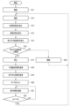
- FIG. 10 is a flowchart for explaining an operation example of the supply device 10.
- the processor 301 of the supply device 10 starts the operation of separating the processing object S (S11).
- the processor 301 also starts driving the input conveyor 12 .
- the processor 301 acquires a photographed image from the photographing means 101 (S12). After obtaining the captured image, the processor 301 extracts a target object area from the captured image (S13).
- the processor 301 calculates an area ratio group AR based on the object area (S14). After calculating the area ratio group AR, the processor 301 calculates a partial average area ratio based on the area ratio group AR (S15).
- the processor 301 determines whether the partial average area ratio is equal to or greater than the stop determination threshold (S16). When determining that the partial average area ratio is equal to or greater than the stop determination threshold (S16, YES), the processor 301 stops the input conveyor 12 (S17).
- the processor 301 estimates the downstream transport time T1 based on the area ratio group AR (S18). After estimating the downstream transport time T1, the processor 301 estimates the drop waiting time T2 based on the first detection result and the second detection result (S19).
- the processor 301 After estimating the drop waiting time T2, the processor 301 sets the stop time in the timer Tr based on the downstream transport time T1 and the drop waiting time T2 (S20). After setting the stop time in the timer Tr, the processor 301 updates the timer Tr (S21). After updating the timer Tr, the processor 301 determines whether the timer Tr is 0 (S22).
- the processor 301 When determining that the timer Tr is not 0 (S22, NO), the processor 301 returns to S21.
- the processor 301 When determining that the timer Tr is 0 (S22, YES), the processor 301 returns to S12.
- the processor 301 drives the input conveyor 12 (S23). After driving the input conveyor 12, the processor 301 returns to S12.
- the processor 301 may discretely or continuously reduce the transport speed of the input conveyor 12.
- the processor 301 may divide the area ratio detection region 201 in either the X-axis direction or the Y-axis direction. That is, the processor 301 may divide the area ratio detection region 201 in the row direction or the column direction. Also, the processor 301 does not have to divide the area ratio detection region 201 into a grid pattern. The shape of the divided regions is not limited to a specific configuration.
- the supply device 10 may be provided with a photographing means for photographing from a direction orthogonal to the conveying direction and the vertical direction of the first conveyor 22 . That is, the supply device 10 may include a photographing means for photographing the processing object S from the side. In this case, the processor 301 may determine whether to stop the input conveyor 12 and/or estimate the downstream transport time T1 further based on the image taken from the side. Also, one or both of the photographing means may be composed of a line sensor or a fiber sensor arranged in an array.
- the supply device 10 may be provided with a distance sensor that measures the distance to each point on the first conveyor 22 .
- the processor 301 may determine whether to stop the input conveyor 12 and/or estimate the downstream transport time T1, further based on the detection result of the distance sensor.
- the feeding device 10 may be provided with a distance sensor instead of the photographing means 101 .
- the processor 301 determines that the partial average area ratio is equal to or greater than the stop determination threshold, if the first fall sign detection sensor 102a and the second fall sign detection sensor 102b have not detected the processing object S, The conveyor 12 may not be stopped. In this case, the processor 301 continues to drive the input conveyor 12 until either or both of the first fall sign detection sensor 102a and the second fall sign detection sensor 102b detect the processing object S. Also, in this case, the processor 301 continues updating the timer Tr from the point of time when it is determined that the partial average area ratio is equal to or greater than the stop determination threshold. A time obtained by subtracting the time obtained by subtracting T2 from the processing time of S18 and S19 may be set.
- the processor 301 may update the transportation time estimation model and/or the waiting time estimation model based on data acquired during operation. For example, the processor 301 may update the transportation time estimation model based on the detection signal from the adjusting section passage detection sensor 103 .
- the processor 301 may detect a sign of falling from the input conveyor 12 based on the captured image from the imaging means 101 .
- the photographing area 101A of the photographing means 101 includes a detection area (for example, the downstream end of the input conveyor 12, or the upstream end of the first conveyor 22, etc.) for detecting a sign of falling.
- Processor 301 calculates the area ratio in the detection area. After calculating the area ratio, the processor 301 sets two thresholds for the calculated area ratio. The processor 301 compares the area ratio and each threshold, and acquires the comparison results as the first detection result and the second detection result.
- the supply device configured as described above stops the input conveyor when the first conveyor is filled with objects to be processed.
- the supply device stops the input conveyor until the downstream transportation time of the group of processing objects has elapsed after stopping the input conveyor.
- the supply device can load the subsequent processing object onto the speed control conveyor at the timing when the processing target object group has been loaded onto the speed control conveyor. Therefore, the supply device can reduce variations in throughput.
Abstract
Description
供給装置10は、多層の荷物を離間(分離)させ、例えば物流システムにおいて、宛先毎に区分する区分装置などに対して所定の時間間隔(所定のピッチ)で物品(処理対象物)を供給する。また、供給装置10は、例えば製造ラインの一部にあり、多数の同種又は異種の部品(処理対象物)を離間(分離)し、後続の装置に所定の時間間隔(所定のピッチ)で部品(処理対象物)を供給するものであってもよい。 The
The
撮影手段101は、下方を撮影するように設置されている。即ち、撮影手段101は、第1コンベア22を上方から撮影する。たとえば、撮影手段101は、照明及びカメラなどから構成される。 In addition, as shown in FIGS. 2 and 4, photographing means 101 is formed above the
The photographing means 101 is installed so as to photograph the downward direction. That is, the photographing means 101 photographs the
調整部通過検知センサ103は、細幅コンベア62を通過し調速コンベア64に投入される処理対象物Sを検知する。 Further, at the downstream end of the
The adjustment unit
図5は、供給装置10の制御系の構成例を示すブロック図である。図5が示すように、供給装置10は、プロセッサ301、メモリ302、撮影手段101、第1落下予兆検知センサ102a、第2落下予兆検知センサ102b、投入コンベア12、調整部通過検知センサ103及び調速コンベア64などを備える。 Next, a control system of the
FIG. 5 is a block diagram showing a configuration example of a control system of the
たとえば、メモリ302は、制御プログラム及び制御データなどを記憶する。制御プログラム及び制御データは、供給装置10の仕様に応じて予め組み込まれる。たとえば、制御プログラムは、供給装置10で実現する機能をサポートするプログラムなどである。
For example, the
ここでは、プロセッサ301は、各分割領域における面積率を含む面積率群ARを取得する。 After calculating the area of the object region overlapping each divided region, the
Here, the
また、プロセッサ301は、他の領域における分割領域の面積率に基づいて投入コンベア12を停止するかを判定してもよい。 Note that the
The
図9は、下流搬送時間T1を説明するための図である。図9は、時刻tにおいて細幅コンベア62及び調速コンベア64が積載する処理対象物群GSの状態と、時刻t+下流搬送時間T1において細幅コンベア62及び調速コンベア64が積載する処理対象物群GSの状態と、を示す。 The
FIG. 9 is a diagram for explaining the downstream transport time T1. FIG. 9 shows the state of the processing object group GS loaded by the
たとえば、搬送時間推測モデルは、領域402における分割領域の面積率を説明変数とし、処理対象物群GSが細幅コンベア62から調速コンベア64へ搬送される実際の時間を目的変数とする重回帰モデルである。搬送時間推測モデルは、事前に収集された説明変数と目的変数とに基づいて生成される。 The transportation time estimation model is pre-stored in the
For example, the transportation time estimation model is a multiple regression using the area ratio of the divided regions in the
搬送時間推測モデルの構成は、特定の構成に限定されるものではない。 The transportation time estimation model may be a model obtained by machine learning such as a neural network.
The configuration of the transportation time estimation model is not limited to a specific configuration.
たとえば、待ち時間推測モデルは、事前に取得された第1検知結果及び第2検知結果と現実の落下待ち時間とに基づく統計モデル(たとえば、正規分布など)である。 The waiting time estimation model is pre-stored in the
For example, the waiting time estimation model is a statistical model (eg, normal distribution, etc.) based on the first and second sensing results obtained in advance and the actual drop waiting time.
待ち時間推測モデルの構成は、特定の構成に限定されるものではない。 Note that the waiting time estimation model may be a model (network) obtained by machine learning.
The configuration of the latency estimation model is not limited to any particular configuration.
図10は、供給装置10の動作例について説明するためのフローチャートである。 Next, an operation example of the
FIG. 10 is a flowchart for explaining an operation example of the
また、プロセッサ301は、停止時間として、下流搬送時間T1から落下待ち時間T2を減算した時間とS18及びS19の処理時間とを減算した時間を設定してもよい。 Further, when the
Claims (11)
- 物品を投入する投入コンベアと、
前記投入コンベアが投入する前記物品を受領する受領コンベアと、
前記受領コンベアに積載されている前記物品を撮影するカメラと、
前記カメラが撮影した撮影画像から前記物品が写る物品領域を抽出し、
前記物品領域に基づいて、前記撮影画像において前記物品領域が示す面積率を算出し、
前記面積率に基づいて、前記投入コンベアを停止し、
前記面積率に基づいて、前記投入コンベアを停止する停止時間を設定する、
プロセッサと、
を備える供給装置。 an input conveyor for inputting articles;
a receiving conveyor that receives the article that is input by the input conveyor;
a camera for photographing the articles loaded on the receiving conveyor;
extracting an article area in which the article is captured from the photographed image taken by the camera;
calculating an area ratio indicated by the article region in the photographed image based on the article region;
Stopping the input conveyor based on the area ratio,
setting a stop time for stopping the input conveyor based on the area ratio;
a processor;
A feeding device comprising: - 前記プロセッサは、
前記撮影画像において前記受領コンベアを含む面積率検出領域を設定し、
前記面積率検出領域において前記面積率を算出する、
請求項1に記載の供給装置。 The processor
setting an area ratio detection area including the receiving conveyor in the captured image;
calculating the area ratio in the area ratio detection region;
2. A supply device according to claim 1. - 前記プロセッサは、
前記面積率検出領域を複数の分割領域に分割し、
前記面積率として、前記各分割領域において面積率を算出する、
請求項2に記載の供給装置。 The processor
dividing the area ratio detection region into a plurality of divided regions;
calculating an area ratio in each of the divided regions as the area ratio;
3. A supply device according to claim 2. - 前記プロセッサは、
前記投入コンベアから前記物品が落下する落下領域における前記分割領域の面積率に基づいて前記投入コンベアを停止する、
請求項3に記載の供給装置。 The processor
stopping the input conveyor based on the area ratio of the divided areas in the drop area where the article falls from the input conveyor;
4. A feeding device according to claim 3. - 前記プロセッサは、
前記落下領域における前記分割領域の面積率の平均値が所定の閾値以上である場合、前記投入コンベアを停止する、
請求項4に記載の供給装置。 The processor
stopping the input conveyor when the average value of the area ratios of the divided areas in the drop area is equal to or greater than a predetermined threshold;
5. A supply device according to claim 4. - 前記プロセッサは、
前記受領コンベアに積載されている前記物品が写る積載領域における前記分割領域の面積率に基づいて前記停止時間を設定する、
請求項3乃至5の何れか1項に記載の供給装置。 The processor
setting the stop time based on the area ratio of the divided areas in the loading area where the articles loaded on the receiving conveyor are reflected;
6. A feeding device according to any one of claims 3-5. - 離間された前記物品を搬送する下流コンベアを備え、
前記プロセッサは、
前記積載領域における前記分割領域の面積率に基づいて、前記受領コンベアに積載されている前記物品が前記下流コンベアを通過する下流搬送時間を推測し、
前記下流搬送時間に基づいて、前記停止時間を設定する、
請求項6に記載の供給装置。 comprising a downstream conveyor that conveys the spaced apart items;
The processor
estimating a downstream transportation time for the articles loaded on the receiving conveyor to pass through the downstream conveyor based on the area ratio of the divided areas in the loading area;
setting the stop time based on the downstream transport time;
7. Feeding device according to claim 6. - 前記プロセッサは、
前記投入コンベアから前記受領コンベアへ落下する予兆を検出した検知結果に基づいて、前記投入コンベアを駆動してから前記物品が前記受領コンベアに落下するまでの落下待ち時間を推測し、
前記落下待ち時間にさらに基づいて、前記停止時間を設定する、
請求項7に記載の供給装置。 The processor
estimating a drop waiting time from when the input conveyor is driven to when the article drops onto the receiving conveyor, based on a detection result of detecting a sign that the article will drop from the input conveyor to the receiving conveyor;
setting the stop time further based on the fall latency;
8. Feeding device according to claim 7. - 前記プロセッサは、前記下流搬送時間から前記落下待ち時間を減算した時間を前記停止時間として設定する、
請求項8に記載の供給装置。 The processor sets a time obtained by subtracting the drop waiting time from the downstream transport time as the stop time.
9. Feeding device according to claim 8. - 前記投入コンベアから前記受領コンベアへ落下する予兆を検知して前記検知結果を出力する落下予兆検知センサを備える、
請求項8又は9に記載の供給装置。 A drop sign detection sensor that detects a sign of dropping from the input conveyor to the receiving conveyor and outputs the detection result,
10. Feeding device according to claim 8 or 9. - 前記落下予兆検知センサは、前記投入コンベアにおいて所定の位置に積載されている前記物品を検知する第1落下予兆検知センサと、前記所定の位置よりも上流に積載されている前記物品を検知する第2落下予兆検知センサと、をから構成され、
前記検知結果は、前記第1落下予兆検知センサからの第1検知結果と、前記第1落下予兆検知センサからの第2検知結果と、から構成される、
請求項10に記載の供給装置。 The drop sign detection sensors include a first drop sign detection sensor that detects the articles loaded at a predetermined position on the input conveyor, and a second drop sign detection sensor that detects the articles loaded upstream of the predetermined position. 2 fall sign detection sensor and,
The detection result is composed of a first detection result from the first fall sign detection sensor and a second detection result from the first fall sign detection sensor.
11. Feeding device according to claim 10.
Priority Applications (2)
| Application Number | Priority Date | Filing Date | Title |
|---|---|---|---|
| AU2022352126A AU2022352126A1 (en) | 2021-09-21 | 2022-09-14 | Supply apparatus |
| CA3231943A CA3231943A1 (en) | 2021-09-21 | 2022-09-14 | Supply apparatus |
Applications Claiming Priority (2)
| Application Number | Priority Date | Filing Date | Title |
|---|---|---|---|
| JP2021-153208 | 2021-09-21 | ||
| JP2021153208A JP2023045031A (en) | 2021-09-21 | 2021-09-21 | Supply device |
Publications (1)
| Publication Number | Publication Date |
|---|---|
| WO2023048032A1 true WO2023048032A1 (en) | 2023-03-30 |
Family
ID=85720614
Family Applications (1)
| Application Number | Title | Priority Date | Filing Date |
|---|---|---|---|
| PCT/JP2022/034305 WO2023048032A1 (en) | 2021-09-21 | 2022-09-14 | Supply device |
Country Status (4)
| Country | Link |
|---|---|
| JP (1) | JP2023045031A (en) |
| AU (1) | AU2022352126A1 (en) |
| CA (1) | CA3231943A1 (en) |
| WO (1) | WO2023048032A1 (en) |
Citations (3)
| Publication number | Priority date | Publication date | Assignee | Title |
|---|---|---|---|---|
| JP4297265B2 (en) * | 2003-11-14 | 2009-07-15 | 株式会社冨士製作所 | Dry food quantitative supply equipment |
| JP5464177B2 (en) * | 2011-06-20 | 2014-04-09 | 株式会社安川電機 | Picking system |
| JP2020529303A (en) * | 2017-05-05 | 2020-10-08 | ファイブス・イントラロジスティクス・コーポレイションFives Intralogistics Corp. | Visual-based article classification and sorting system |
-
2021
- 2021-09-21 JP JP2021153208A patent/JP2023045031A/en active Pending
-
2022
- 2022-09-14 WO PCT/JP2022/034305 patent/WO2023048032A1/en active Application Filing
- 2022-09-14 AU AU2022352126A patent/AU2022352126A1/en active Pending
- 2022-09-14 CA CA3231943A patent/CA3231943A1/en active Pending
Patent Citations (3)
| Publication number | Priority date | Publication date | Assignee | Title |
|---|---|---|---|---|
| JP4297265B2 (en) * | 2003-11-14 | 2009-07-15 | 株式会社冨士製作所 | Dry food quantitative supply equipment |
| JP5464177B2 (en) * | 2011-06-20 | 2014-04-09 | 株式会社安川電機 | Picking system |
| JP2020529303A (en) * | 2017-05-05 | 2020-10-08 | ファイブス・イントラロジスティクス・コーポレイションFives Intralogistics Corp. | Visual-based article classification and sorting system |
Also Published As
| Publication number | Publication date |
|---|---|
| AU2022352126A1 (en) | 2024-04-04 |
| CA3231943A1 (en) | 2023-03-30 |
| JP2023045031A (en) | 2023-04-03 |
Similar Documents
| Publication | Publication Date | Title |
|---|---|---|
| US10427884B2 (en) | Vision based conveyor package density management system | |
| US10906746B2 (en) | Article typing and sorting system | |
| CA2541298C (en) | Conveyor with probability estimator | |
| US8061506B2 (en) | Material-flow control for collision avoidance in a conveyor system | |
| US9624043B2 (en) | High rate bulk flow sortation | |
| CN109205231A (en) | Dynamic discharging for separation system compensates | |
| US10815069B1 (en) | Parcel singulation systems and methods | |
| WO2021161341A1 (en) | System for modular multi-grade sorting and a method thereof | |
| JP2018536606A (en) | Article sorting equipment and system including a system for detecting and analyzing the route of an article | |
| TWI805716B (en) | Conveying sorting device | |
| US9776796B2 (en) | System and method for destacking and conveying articles arranged in stacks | |
| JP3111021B2 (en) | Alignment transfer device | |
| WO2023048032A1 (en) | Supply device | |
| JP3679843B2 (en) | Article counting device by image processing | |
| JP2023045039A (en) | Supply device | |
| WO2023058446A1 (en) | Package conveying device and package supply device | |
| JP2003104532A (en) | Mergence control system | |
| WO2021205733A1 (en) | Feeding device | |
| US20220180094A1 (en) | Package detection and intelligent sorting | |
| WO2020190255A1 (en) | Parcel singulation systems and methods | |
| US7915557B2 (en) | Method and arrangement for synchronizing the distribution information of sorting stock with the information relating to a sorter element loaded with this sorting stock | |
| JP2022164151A (en) | Article conveyance system and feeder | |
| JP2001019152A (en) | Joining device for conveyed articles | |
| JP5834785B2 (en) | Article input equipment and article fall prevention method in the equipment | |
| JP7326904B2 (en) | Sorting device |
Legal Events
| Date | Code | Title | Description |
|---|---|---|---|
| 121 | Ep: the epo has been informed by wipo that ep was designated in this application |
Ref document number: 22872786 Country of ref document: EP Kind code of ref document: A1 |
|
| WWE | Wipo information: entry into national phase |
Ref document number: 3231943 Country of ref document: CA |
|
| WWE | Wipo information: entry into national phase |
Ref document number: 2022352126 Country of ref document: AU Ref document number: AU2022352126 Country of ref document: AU |
|
| ENP | Entry into the national phase |
Ref document number: 2022352126 Country of ref document: AU Date of ref document: 20220914 Kind code of ref document: A |