WO2023047774A1 - 推定装置、推定装置の駆動方法、及びプログラム - Google Patents
推定装置、推定装置の駆動方法、及びプログラム Download PDFInfo
- Publication number
- WO2023047774A1 WO2023047774A1 PCT/JP2022/027948 JP2022027948W WO2023047774A1 WO 2023047774 A1 WO2023047774 A1 WO 2023047774A1 JP 2022027948 W JP2022027948 W JP 2022027948W WO 2023047774 A1 WO2023047774 A1 WO 2023047774A1
- Authority
- WO
- WIPO (PCT)
- Prior art keywords
- model
- reference image
- image
- tracking
- imaging
- Prior art date
- Legal status (The legal status is an assumption and is not a legal conclusion. Google has not performed a legal analysis and makes no representation as to the accuracy of the status listed.)
- Ceased
Links
Images







Classifications
-
- H—ELECTRICITY
- H04—ELECTRIC COMMUNICATION TECHNIQUE
- H04N—PICTORIAL COMMUNICATION, e.g. TELEVISION
- H04N23/00—Cameras or camera modules comprising electronic image sensors; Control thereof
- H04N23/60—Control of cameras or camera modules
- H04N23/69—Control of means for changing angle of the field of view, e.g. optical zoom objectives or electronic zooming
-
- G—PHYSICS
- G06—COMPUTING OR CALCULATING; COUNTING
- G06T—IMAGE DATA PROCESSING OR GENERATION, IN GENERAL
- G06T7/00—Image analysis
-
- G—PHYSICS
- G06—COMPUTING OR CALCULATING; COUNTING
- G06T—IMAGE DATA PROCESSING OR GENERATION, IN GENERAL
- G06T7/00—Image analysis
- G06T7/20—Analysis of motion
-
- G—PHYSICS
- G06—COMPUTING OR CALCULATING; COUNTING
- G06T—IMAGE DATA PROCESSING OR GENERATION, IN GENERAL
- G06T7/00—Image analysis
- G06T7/20—Analysis of motion
- G06T7/246—Analysis of motion using feature-based methods, e.g. the tracking of corners or segments
-
- G—PHYSICS
- G06—COMPUTING OR CALCULATING; COUNTING
- G06T—IMAGE DATA PROCESSING OR GENERATION, IN GENERAL
- G06T7/00—Image analysis
- G06T7/20—Analysis of motion
- G06T7/246—Analysis of motion using feature-based methods, e.g. the tracking of corners or segments
- G06T7/248—Analysis of motion using feature-based methods, e.g. the tracking of corners or segments involving reference images or patches
-
- G—PHYSICS
- G06—COMPUTING OR CALCULATING; COUNTING
- G06T—IMAGE DATA PROCESSING OR GENERATION, IN GENERAL
- G06T7/00—Image analysis
- G06T7/70—Determining position or orientation of objects or cameras
Definitions
- the technology of the present disclosure relates to an estimation device, an estimation device driving method, and a program.
- Japanese Patent Application Laid-Open No. 2020-038410 describes a DNN processing unit that performs DNN on an input image based on a DNN (Deep Neural Network) model, and receives control information generated based on evaluation information of DNN execution results. , and a DNN controller that changes the DNN model based on control information.
- DNN Deep Neural Network
- Japanese Patent Application Laid-Open No. 2019-118097 discloses a selection step of performing a process of selecting one of a learning model from among a plurality of learning models that have learned criteria for recording an image generated by an image sensor; a determination step of determining whether or not the image generated by the imaging device satisfies the criteria using the learned model, and when it is determined in the determination processing that the image generated by the imaging device meets the criteria and a recording step of recording an image generated by the image sensor in a memory.
- the process of selecting one of the learning models includes the shooting instruction by the user, the evaluation result of the image by the user, the environment when the image was generated by the image sensor, and the scores of the images generated by the image sensor of the plurality of learning models. and/or
- An embodiment according to the technology of the present disclosure provides an estimation device, a method for driving the estimation device, and a program that make it possible to achieve both subject tracking accuracy and real-time performance.
- an estimation device of the present disclosure includes a memory that stores a first model and a second model that have undergone machine learning for subject tracking, and a processor that receives an image signal from an image sensor. wherein the processor performs determination processing for determining a tracking subject to be tracked, a first reference image for the first model including the tracking subject, and a second reference image for the second model including the tracking subject, a first creation process for creating based on the imaging signal; a selection process for selecting one of the first model and the second model as the selected model based on the factor information; and a captured image represented by the imaging signal as the selected model.
- Input processing for inputting, and estimation processing for estimating the position of the tracking subject from the captured image using the selected model and the reference image for the selected model among the first reference image and the second reference image. configured to run.
- the second model preferably has more layers or a larger size of layers than the first model.
- the second reference image preferably has a higher resolution than the first reference image.
- the factor information is preferably the type of the tracking subject, the moving speed of the tracking subject, or the degree of change in the form of the tracking subject.
- the factor information is preferably the value of the frame rate of the captured image input to the selection model.
- the processor is configured to be able to execute a second creation process in which the first reference image is created and the second reference image is not created, instead of the first creation process. It is preferred to select the process or the second creation process.
- the processor is configured to perform a first update process of updating the first reference image and the second reference image when the selected model is switched from one of the first model and the second model to the other in the selection process. It is preferable that
- the processor is preferably configured to execute a second update process for updating the first reference image and the second reference image based on a change in size within the angle of view of the captured image of the tracking subject.
- the processor is preferably configured to execute the second update process based on changes in imaging magnification of an imaging device having an imaging element.
- a method of driving an estimating device is a method of driving an estimating device including a memory storing a first model and a second model subjected to machine learning for object tracking, and receiving an image signal from an image sensor.
- a program of the present disclosure is a program for operating an estimating device including a memory that stores a first model and a second model subjected to machine learning for subject tracking, and is a receiving process for receiving an image signal from an image sensor;
- a determination process for determining a tracking subject to be tracked, a first reference image for the first model including the tracking subject, and a second reference image for the second model including the tracking subject are created based on the imaging signal.
- the estimating device is caused to perform an estimating process of estimating the position of the tracking subject from the captured image using the model and the reference image for the selected model among the first reference image and the second reference image.
- FIG. 3 is a block diagram showing an example of a functional configuration of a processor;
- FIG. FIG. 4 is a diagram conceptually showing an example of a tracking subject determination process and a reference image creation process; It is a figure which shows an example of a structure of a 1st model. It is a figure which shows an example of a structure of a 2nd model. It is a figure which shows an example of the teacher data used for the machine learning of a 1st model.
- FIG. 10 is a diagram showing an example of teacher data used for machine learning of the second model; It is a figure which shows an example of a score map.
- 4 is a flowchart for explaining a processing procedure of a subject tracking function; FIG.
- FIG. 10 is a diagram showing an example in which an image cut out from a captured image is used as a search image;
- FIG. 11 is a flow chart showing processing for creating a reference image according to a modification;
- FIG. 11 is a flow chart for explaining a processing procedure of a subject tracking function according to a modified example;
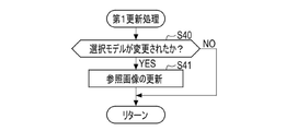
- FIG. 9 is a flowchart illustrating an example of a processing procedure of first update processing;
- FIG. 11 is a flowchart showing another example of the processing procedure of the first update process;
- FIG. FIG. 11 is a flow chart showing an example of a processing procedure of a second update process;
- IC is an abbreviation for “Integrated Circuit”.
- CPU is an abbreviation for "Central Processing Unit”.
- ROM is an abbreviation for “Read Only Memory”.
- RAM is an abbreviation for “Random Access Memory”.
- CMOS is an abbreviation for "Complementary Metal Oxide Semiconductor.”
- FPGA is an abbreviation for "Field Programmable Gate Array”.
- PLD is an abbreviation for "Programmable Logic Device”.
- ASIC is an abbreviation for "Application Specific Integrated Circuit”.
- OVF is an abbreviation for "Optical View Finder”.
- EVF is an abbreviation for "Electronic View Finder”.
- JPEG is an abbreviation for "Joint Photographic Experts Group”.
- CNN is an abbreviation for "Convolutional Neural Network”.
- the technology of the present disclosure will be described by taking a lens-interchangeable digital camera as an example.
- the technique of the present disclosure is not limited to interchangeable-lens type digital cameras, and can be applied to lens-integrated digital cameras.
- FIG. 1 shows an example of the configuration of the imaging device 10.
- the imaging device 10 is a lens-interchangeable digital camera.
- the imaging device 10 is composed of a body 11 and an imaging lens 12 replaceably attached to the body 11 .
- the imaging lens 12 is attached to the front side of the main body 11 via a camera side mount 11A and a lens side mount 12A.
- the main body 11 is provided with an operation unit 13 including dials, a release button, and the like.
- the operation modes of the imaging device 10 include, for example, a still image imaging mode, a moving image imaging mode, and an image display mode.
- the operation unit 13 is operated by the user when setting the operation mode. Further, the operation unit 13 is operated by the user when starting execution of still image capturing or moving image capturing. Note that the operation unit 13 includes a touch panel provided on a display 15 or the like, which will be described later.
- the imaging device 10 is provided with a subject tracking function that tracks a subject specified by the user as a tracking target in the moving image imaging mode.
- the subject tracking function can also be activated during live view image display executed before still image capturing or moving image capturing.
- the imaging device 10 is an example of an “estimation device” according to the technology of the present disclosure.
- the main body 11 is provided with a finder 14 .
- the finder 14 is a hybrid finder (registered trademark).
- a hybrid viewfinder is, for example, a viewfinder that selectively uses an optical viewfinder (hereinafter referred to as "OVF") and an electronic viewfinder (hereinafter referred to as "EVF").
- OVF optical viewfinder
- EMF electronic viewfinder
- a user can observe an optical image or a live view image of a subject projected through the viewfinder 14 through a viewfinder eyepiece (not shown).
- a display 15 is provided on the back side of the main body 11 .
- the display 15 displays an image based on an image signal obtained by imaging, various menu screens, and the like. The user can also observe a live view image projected on the display 15 instead of the viewfinder 14 .
- the body 11 and the imaging lens 12 are electrically connected by contact between an electrical contact 11B provided on the camera side mount 11A and an electrical contact 12B provided on the lens side mount 12A.
- the imaging lens 12 includes an objective lens 30, a focus lens 31, a rear end lens 32, and an aperture 33. Each member is arranged along the optical axis A of the imaging lens 12 in the order of the objective lens 30, the diaphragm 33, the focus lens 31, and the rear end lens 32 from the objective side.
- the objective lens 30, focus lens 31, and rear end lens 32 constitute an imaging optical system.
- the type, number, and order of arrangement of lenses that constitute the imaging optical system are not limited to the example shown in FIG.
- the imaging lens 12 also has a lens drive control section 34 .
- the lens drive control unit 34 is composed of, for example, a CPU, a RAM, a ROM, and the like.
- the lens drive control section 34 is electrically connected to the processor 40 in the main body 11 via the electrical contacts 12B and 11B.
- the lens drive control unit 34 drives the focus lens 31 and the diaphragm 33 based on control signals sent from the processor 40 .
- the lens drive control unit 34 performs drive control of the focus lens 31 based on a control signal for focus control transmitted from the processor 40 in order to adjust the focus position of the imaging lens 12 .
- the processor 40 may perform focus control based on an estimation result R representing the position of the tracking subject, which will be described later.
- the diaphragm 33 has an aperture whose aperture diameter is variable around the optical axis A.
- the lens drive control unit 34 performs drive control of the diaphragm 33 based on the control signal for diaphragm adjustment transmitted from the processor 40.
- an imaging sensor 20 a processor 40, and a memory 42 are provided inside the main body 11.
- the operations of the imaging sensor 20 , the memory 42 , the operation unit 13 , the viewfinder 14 and the display 15 are controlled by the processor 40 .
- the processor 40 is composed of, for example, a CPU, RAM, and ROM. In this case, processor 40 executes various processes based on program 43 stored in memory 42 . Note that the processor 40 may be configured by an assembly of a plurality of IC chips.
- the memory 42 stores a first model M1 and a second model M2 that have undergone machine learning for object tracking.
- the first model M1 and the second model M2 are configured by neural networks, and the second model M2 is larger in scale than the first model M1.
- a large scale means that the number of layers (convolutional layers, pooling layers, fully connected layers, etc.) constituting the neural network is large and/or the layer size (the number of neurons constituting the layer) is large. Since the first model M1 is small in scale, the tracking object estimation process is fast, but the estimation accuracy is low. Conversely, since the second model M2 has a large scale, the estimation processing of the tracking object is slow, but the accuracy of object tracking is high.
- the imaging sensor 20 is, for example, a CMOS image sensor.
- the imaging sensor 20 is arranged such that the optical axis A is orthogonal to the light receiving surface 20A and the optical axis A is positioned at the center of the light receiving surface 20A.
- Light (subject image) that has passed through the imaging lens 12 is incident on the light receiving surface 20A.
- a plurality of pixels that generate image signals by performing photoelectric conversion are formed on the light receiving surface 20A.
- the imaging sensor 20 photoelectrically converts light incident on each pixel to generate and output an image signal.
- the imaging sensor 20 is an example of an “imaging element” according to the technology of the present disclosure.
- a color filter array of Bayer arrangement is arranged on the light receiving surface of the imaging sensor 20, and one of R (red), G (green), and B (blue) color filters is arranged opposite to each pixel. It is Note that some of the plurality of pixels arranged on the light receiving surface of the imaging sensor 20 may be phase difference pixels for performing focus control.
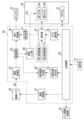
- FIG. 2 shows an example of the functional configuration of the processor 40.
- the processor 40 implements various functional units by executing processes according to programs 43 stored in the memory 42 .
- the processor 40 includes a main control unit 50, an imaging control unit 51, an image processing unit 52, a tracking target determination unit 53, a reference image creation unit 54, a model selection unit 55, and an image input unit 56. , an estimation unit 57, and a display control unit 58 are realized.
- the main control unit 50 comprehensively controls the operation of the imaging device 10 based on instruction signals input from the operation unit 13 .
- the imaging control unit 51 controls the imaging sensor 20 to perform an imaging process for causing the imaging sensor 20 to perform an imaging operation.
- the imaging control unit 51 drives the imaging sensor 20 in still image imaging mode or moving image imaging mode.
- the imaging sensor 20 outputs an imaging signal RD generated by the imaging operation.
- the imaging signal RD is so-called RAW data.
- the image processing unit 52 performs reception processing for receiving the imaging signal RD output from the imaging sensor 20 . Further, the image processing unit 52 generates a captured image PD by performing image processing including demosaic processing and the like on the received captured image signal RD.
- the captured image PD is a color image in which each pixel is represented by the three primary colors of R, G, and B. More specifically, for example, the captured image PD is a 24-bit color image in which each of the R, G, and B signals included in one pixel is represented by 8 bits.
- the tracking target determination unit 53 performs determination processing for determining the subject specified by the user as the tracking target. For example, the user uses the operation unit 13 to specify a subject to be tracked from within the captured image PD displayed on the display 15 . The tracking target determination unit 53 determines the subject specified by the user from within the captured image PD as the tracking subject to be tracked.
- the tracking target determination unit 53 may determine a specific subject detected by the subject detection function as the tracking subject. good.
- the reference image creating unit 54 captures the first reference image T1 for the first model including the tracking subject determined by the tracking target determining unit 53 and the second reference image T2 for the second model including the tracking subject. Creation processing for creating based on the image PD is performed.
- the creation process in this embodiment corresponds to the "first creation process" according to the technology of the present disclosure.
- the reference image creation unit 54 creates the first reference image T1 and the second reference image T2 by cutting out the area including the tracking subject from within the captured image PD.
- the second reference image T2 is a reference image for the second model M2, which is larger in scale than the first model M1, and therefore has a higher resolution than the first reference image T1.
- High resolution means that the amount of information is large, such as the number of pixels in an image, the amount of data of high-frequency components being large, and the number of bits of each pixel constituting the image being large.
- a reference image is a so-called template.
- the model selection unit 55 performs a selection process of selecting one of the first model M1 and the second model M2 stored in the memory 42 as the selected model based on the factor information.
- the model selection unit 55 performs selection processing using the value of the frame rate as factor information.
- the frame rate is the reciprocal of the repetition cycle of the imaging operation of the imaging sensor 20 .
- the value of the frame rate is changed, for example, by a setting operation using the operation unit 13 by the user.
- the value of the frame rate may be lowered by selecting a synthesis mode for synthesizing images of a plurality of frames in order to increase the brightness of the image.
- the first model M1 has high-speed estimation processing but low estimation accuracy, so it is suitable for tracking an object whose shape changes or blurring amount is small between frames.
- the frame rate is high, while high-speed object tracking processing is required, the time difference between frames is small, and the change in shape of the object or the amount of blur is small.
- the second model M2 has a slow estimation process but a high estimation accuracy, so it is suitable for tracking a subject whose shape changes or blurs greatly between frames.
- the frame rate is low, high-speed object tracking processing is not necessary, but the time difference between frames is large, and the shape change or blur amount of the object is large.
- the image input unit 56 performs input processing for inputting the captured image PD represented by the captured image signal RD into the selected model selected by the model selection unit 55 .
- the captured image PD that the model selection unit 55 inputs to the selected model is a search image for searching for a tracking subject included in the reference image.
- the image input unit 56 changes the resolution of the captured image PD input to the selection model according to the resolution of the reference image input to the selection model.
- the image input unit 56 makes the resolution of the captured image PD higher than when the selected model is the first model M1.
- the estimation unit 57 uses the selected model selected by the model selection unit 55 and the reference image for the selected model to perform estimation processing for estimating the position of the tracking subject from the captured image PD. Specifically, when the model selection unit 55 selects the first model M1, the estimation unit 57 inputs the first reference image T1 to the selected model. On the other hand, when the model selection unit 55 selects the second model M2, the estimation unit 57 inputs the second reference image T2 to the selected model.
- the selection model outputs a score map SM that represents the degree of similarity between each region in the captured image PD and the reference image.
- the estimating unit 57 outputs the information of the position with the highest score (that is, the highest degree of similarity) in the score map SM to the display control unit 58 as an estimation result R of the position of the tracking subject.
- the display control unit 58 causes the display 15 to display the estimation result R together with the captured image PD. Specifically, based on the estimation result R, the display control unit 58 displays the position of the tracking subject in the captured image PD in a recognizable manner. For example, the display control unit 58 displays a rectangular frame surrounding the tracking subject in the captured image PD.
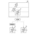
- FIG. 3 conceptually shows an example of a tracking subject determination process and a reference image creation process.
- an area S is an area designated as a tracking target from within the captured image PD by the user using the operation unit 13 .
- the tracking target determination unit 53 determines the subject included in the specified area S as the tracking subject H.
- the reference image creation unit 54 cuts out an area including the tracking subject H from the captured image PD, and reduces the resolution of the cut out image to create the first reference image T1 (in other words, the resolution of the second reference image T2 is , higher than the resolution of the first reference image T1). Further, the reference image creating unit 54 creates a second reference image T2 by cutting out an area including the tracking subject H from the captured image PD.
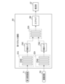
- FIG. 4 shows an example of the configuration of the first model M1.
- the first model M1 is composed of a first convolutional network (hereinafter referred to as first CNN) 61A, a second convolutional network (hereinafter referred to as second CNN) 62A, and a convolution calculator 63A.
- first CNN first convolutional network
- second CNN second convolutional network
- convolution calculator 63A convolution calculator
- the first CNN 61A is composed of multiple convolution layers and multiple pooling layers.
- the second CNN 62A is composed of multiple convolution layers and multiple pooling layers.
- the convolution calculation unit 63A is composed of a plurality of fully connected layers.
- the first reference image T1 is input to the first CNN 61A.
- a captured image PD is input to the second CNN 62A.
- the first CNN 61A converts the input first reference image T1 into a feature map FM1 and outputs the feature map FM1.
- the second CNN 62A converts the input captured image PD into a feature map FM2 and outputs the feature map FM2.
- the feature map FM1 and the feature map FM2 are input to the convolution calculator 63A.
- the first CNN 61A and the second CNN 62A have the same configuration, but the input layer to which the image is input has a size corresponding to the size of the input image (the number of neurons). That is, the size of the input layer differs between the first CNN 61A and the second CNN 62A.
- the convolution operation unit 63A generates a score map SM by convolving the feature map FM2 using the feature map FM1 as a kernel, and outputs the generated score map SM to the estimation unit 57.
- the score map SM is an image representing the degree of similarity between each region in the captured image PD and the first reference image T1. The higher the degree of similarity, the higher the score.
- FIG. 5 shows an example of the configuration of the second model M2.
- the second model M2 is composed of a first CNN 61B, a second CNN 62B, and a convolution calculator 63B.
- the first CNN 61B, the second CNN 62B, and the convolution unit 63B each have more layers than the first CNN 61A, the second CNN 62A, and the convolution unit 63A.
- the first CNN 61B, the second CNN 62B, and the convolution unit 63B may each have a larger layer size than the first CNN 61A, the second CNN 62A, and the convolution unit 63A.
- the second model M2 has the same configuration as the first model M1, except that the number of layers is large and/or the size of the layers is large.
- a large number of layers means a large number of convolutional operation layers or pooling layers.
- a large layer size means that the number of operations or the amount of operations in the convolutional operation layer or the pooling layer is large.
- the second reference image T2 is input to the first CNN 61B.
- a captured image PD is input to the second CNN 62B.
- the first CNN 61B converts the input second reference image T2 into a feature map FM1 and outputs the feature map FM1.
- the second CNN 62B converts the input captured image PD into a feature map FM2 and outputs the feature map FM2.
- the feature map FM1 and the feature map FM2 are input to the convolution calculator 63B.
- the convolution calculation unit 63B generates a score map SM by convolving the feature map FM2 using the feature map FM1 as a kernel, and outputs the generated score map SM to the estimation unit 57.
- FIG. 6 shows an example of teacher data used for machine learning of the first model M1.
- Machine learning of the first model M1 is performed with a set of two frames selected from the moving image. Specifically, machine learning is performed by inputting teacher data, which is a set of a first reference image T1 generated from a first frame and a captured image PD generated from a second frame, to a first model M1. done.
- teacher data which is a set of a first reference image T1 generated from a first frame and a captured image PD generated from a second frame.
- FIG. 7 shows an example of teacher data used for machine learning of the second model M2.
- Machine learning of the second model M2 is performed with a set of two frames selected from the moving image. Specifically, machine learning is performed by inputting teacher data, which is a set of the second reference image T2 generated from the first frame and the captured image PD generated from the second frame, to the second model M2. done.
- teacher data which is a set of the second reference image T2 generated from the first frame and the captured image PD generated from the second frame
- FIG. 8 shows an example of the score map SM.
- the estimating unit 57 specifies, for example, a region U including the position with the highest score in the score map SM, and outputs the positional information of the specified region U to the display control unit 58 as the estimation result R. do.
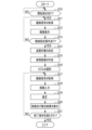
- FIG. 9 is a flowchart for explaining the processing procedure of the subject tracking function when capturing a moving image or displaying a live view image.
- the main control unit 50 determines whether or not the user has operated the operation unit 13 to give an instruction to start capturing a moving image or displaying a live view image (step S10). If there is a start instruction (step S10: YES), the main control unit 50 causes the imaging sensor 20 to perform an imaging operation by controlling the imaging control unit 51, and the imaging signal RD output from the imaging sensor 20 (step S11). The display control unit 58 causes the display 15 to display the picked-up image PD generated by the image processing unit 52 based on the picked-up signal RD (step S12).
- the main control unit 50 determines whether or not the user has specified an area to be tracked from within the captured image PD using the operation unit 13 (step S13). If the user does not designate an area (step S13: NO), the main control unit 50 returns the process to step S11 and causes the imaging sensor 20 to perform an imaging operation. The processes of steps S11 and S12 are repeatedly executed until it is determined in step S13 that the user has specified an area.
- step S13 When the user designates an area (step S13: YES), the main control unit 50 causes the tracking target determination unit 53 to determine the tracking target (step S14). In step S ⁇ b>14 , the tracking target determination unit 53 determines the subject included in the specified area as the tracking subject H.
- FIG. 1 When the user designates an area (step S13: YES), the main control unit 50 causes the tracking target determination unit 53 to determine the tracking target (step S14).
- step S ⁇ b>14 the tracking target determination unit 53 determines the subject included in the specified area as the tracking subject H.
- the reference image creation unit 54 cuts out an area including the tracking subject H from the captured image PD to create a first reference image T1 and a second reference image T2 (step S15).
- the second reference image T2 has a higher resolution than the first reference image T1.
- the model selection unit 55 selects one of the first model M1 and the second model M2 as the selected model, using the value of the frame rate as factor information (step S16). In step S16, the model selection unit 55 selects the first model M1 as the selected model when the frame rate value is equal to or greater than the predetermined value, and selects the first model M1 when the frame rate value is less than the predetermined value. 2. Select model M2 as the selected model.
- the main control unit 50 causes the imaging sensor 20 to perform an imaging operation by controlling the imaging control unit 51, and acquires the imaging signal RD output from the imaging sensor 20 (step S17).
- the image input unit 56 inputs the picked-up image PD generated by the image processing unit 52 based on the picked-up signal RD to the selected model as the resolution corresponding to the selected model selected by the model selecting unit 55 (step S18). .
- the estimation unit 57 inputs the reference image for the selection model selected by the model selection unit 55 from among the first reference image T1 and the second reference image T2 to the selection model, and calculates the score map SM , the position of the tracking object is estimated from the imaging signal RD, and the estimation result R is output to the display control unit 58 (step S19).
- the display control unit 58 causes the display 15 to display the estimation result R together with the captured image PD (step S20).
- the main control unit 50 determines whether or not a predetermined termination condition is satisfied (step S21).
- the end condition is, for example, that the user has performed an operation to stop moving image capturing using the operation unit 13 . If the end condition is not satisfied (step S21: NO), the main control unit 50 returns the process to step S17 and causes the imaging sensor 20 to perform the imaging operation. The processes of steps S17 to S20 are repeatedly executed until it is determined in step S21 that the termination condition is satisfied. When the termination condition is satisfied (step S21: YES), the main control section 50 terminates the process.
- steps S11 and S17 correspond to the "reception process” according to the technology of the present disclosure.
- Step S14 corresponds to the “determining step” according to the technology of the present disclosure.
- Step S15 corresponds to the "first creation step” according to the technology of the present disclosure.
- Step S16 corresponds to the “selection step” according to the technology of the present disclosure.
- Step S18 corresponds to the "input step” according to the technology of the present disclosure.
- Step S19 corresponds to the "estimation step” according to the technology of the present disclosure.
- the small-scale first model M1 is selected with emphasis on real-time performance, and when the frame rate is low, emphasis is placed on subject tracking accuracy.
- the large scale second model M2 is selected.
- the frame rate is high, the shape change or blur amount of the tracking subject between frames is small, so the accuracy of tracking the subject is kept constant even with the first model M1 of small scale.
- the frame cycle is long, so even the large-scale second model M2 maintains constant real-time performance. In this way, according to the technology of the present disclosure, it is possible to achieve both accuracy and real-time tracking of the subject.
- a first reference image T1 for the first model M1 and a second reference image T2 for the second model M2 are created, and the reference image corresponding to the selected model is used for estimation. Since the processing is performed, there is no need to recreate the reference image when switching the selection model. Therefore, real-time performance can be maintained even when the selection model is switched.
- the image input unit 56 inputs the entire captured image PD into the selection model as the search image, but an image cut from the captured image PD may be input into the selection model as the search image.
- the image input unit 56 sets the search range so as to include the region U including the tracking subject estimated by the estimation unit 57 in the previous frame period, and the search range obtained in the current frame period. An image within the search range is cut out from the picked-up image PD and input to the selection model. By limiting the search range in this way, the processing speed of the selection model is improved.
- the reference image creation unit 54 executes creation processing (first creation processing) for creating the first reference image T1 and the second reference image T2 from the captured image PD.
- the reference image creation unit 54 may be configured to be able to execute a second creation process in which the first reference image T1 is created and the second reference image T2 is not created, instead of the first creation process.
- the reference image creation unit 54 selectively executes the first creation process or the second creation process based on the value of the frame rate.
- FIG. 11 shows reference image creation processing according to the modification.
- the processing shown in FIG. 11 is executed, for example, in step S15 of the flowchart shown in FIG.
- the reference image creating unit 54 determines whether or not the value of the frame rate is less than a certain value (step S30). When the value of the frame rate is less than a certain value (step S30: YES), the reference image creating unit 54 executes the first creating process (step S31). On the other hand, when the value of the frame rate is equal to or higher than the fixed value (step S30: NO), the reference image creating unit 54 executes the second creating process (step S32).
- the model selecting unit 55 selects the second model M2 as the selected model, the first creation process is executed, and when the model selecting unit 55 selects the first model M1 as the selected model, the second Creation processing is executed.
- the frame rate is high, processing can be speeded up by not creating the second reference image T2.
- model selection In the above embodiment, the model selection unit 55 performs selection processing using the frame rate value as factor information, but the factor information is not limited to the frame rate value.
- the model selection unit 55 may perform selection processing using the type of the tracking subject determined by the tracking target determination unit 53 as factor information.
- the first model M1 has high-speed estimation processing but low estimation accuracy, so it is suitable for tracking an object whose shape changes little between frames.
- a subject whose shape changes little between frames is an object with high rigidity, such as a vehicle or an aircraft.
- the second model M2 has a slow estimation process but high estimation accuracy, so it is suitable for tracking an object whose shape changes greatly between frames.
- a subject whose shape changes greatly between frames is an object with low rigidity, such as a human being or an animal. Humans, animals, and the like are likely to change their shape due to movement of limbs and the like.
- the selected model is not changed after the model selection unit 55 selects the selected model, but the selected model may be changed according to the factor information that changes during the tracking operation of the subject. For example, as in the flowchart shown in FIG. 12, when the termination condition is not satisfied (step S21: NO), the main control unit 50 returns the process to step S16, and instructs the model selection unit 55 again to select the selected model. to run. In this manner, the model selection unit 55 may repeatedly execute the selection process until the termination condition is satisfied.
- the model selection unit 55 preferably performs selection processing using the moving speed of the tracking subject as factor information.
- the model selection unit 55 selects the second model M2 as the selected model when the moving speed of the tracking object is equal to or higher than a certain value, and selects the first model M1 when the moving speed of the tracking object is less than the certain value. is preferably selected as the model of choice.
- the model selection unit 55 preferably performs selection processing using the degree of change in the form of the tracking subject as factor information.
- the degree of change in form of the tracking subject is, for example, the degree of change in shape or the degree of change in color.
- the model selection unit 55 selects the second model M2 as the selected model when the degree of change in the form of the tracking object between frames is equal to or greater than a certain value, and when the degree of change in the form of the tracking object between frames is less than the certain value. In some cases it is preferable to select the first model M1 as the selected model.
- the model selection unit 55 preferably performs selection processing using the score obtained from the score map SM output from the selected model as factor information. For example, when the first model M1 is selected as the selected model and the maximum score value is less than the threshold, the model selection unit 55 determines that the tracking accuracy has decreased, and determines that the tracking accuracy is high. 2. Select model M2 as the selected model.
- the reference image created by the reference image creating unit 54 is not updated until the subject tracking operation is completed. This is because if the reference image is updated when the tracking subject undergoes posture changes such as rotation during the subject tracking operation, or when occlusion (i.e., intersecting objects) occurs, an object other than the tracking subject may be incorrectly tracked. It is also because it increases the chances of Here, updating means that the reference image creating unit 54 creates a new reference image.
- the reference image creating unit 54 may update the reference image when a specific condition is satisfied.
- the reference image creation unit 54 performs a first update process of updating the first reference image T1 and the second reference image T2. to run. Specifically, immediately after step S16 in the flowchart shown in FIG. 12, the first updating process for the reference image shown in FIG. 13 is executed.
- the reference image creating unit 54 determines whether or not the model selected by the model selecting unit 55 has been changed in step S16 (step S40). If the selected model has not been changed (step S40: NO), the reference image generator 54 does not update the reference image. On the other hand, when the selected model is changed (step S40: YES), the reference image creating unit 54 updates the reference image (step S41). In step S41, the reference image generation unit 54 generates the first reference image T1 based on the image cut out from the region U (see FIG. 8) specified by the estimation unit 57 in the captured image PD obtained in the immediately preceding frame period. and a second reference image T2.
- the reference image creating unit 54 determines that the score (for example, the maximum value) of the region U specified by the estimating unit 57 is It is determined whether or not it is equal to or greater than a certain value (step S42). The reference image creating unit 54 does not update the reference image if the score is not equal to or greater than a certain value (step S42: NO). On the other hand, if the score is equal to or greater than the given value (step S42: YES), the reference image generator 54 updates the reference image (step S41).
- the score for example, the maximum value
- the reference image creation unit 54 may perform a second update process of updating the reference image based on a change in size within the angle of view of the captured image PD of the tracking subject.
- a change in the size of the tracking subject occurs, for example, when the tracking subject approaches the imaging device 10 or moves away from the imaging device 10 .
- the reference image creating unit 54 updates the reference image when the size of the tracking subject changes by a predetermined value or more based on the size of the tracking subject in the reference image. Note that the size of the tracking subject can be detected using the subject detection result obtained by the subject detection function.
- the reference image creating unit 54 updates the reference image when the distance from the imaging device 10 to the tracking object changes by a predetermined value or more. good too.
- a change in the size of the tracking subject can also occur due to a change in the imaging magnification of the imaging device 10 .
- the reference image creating unit 54 updates the reference image when the imaging magnification has changed by a certain value or more after creating the reference image.
- the imaging magnification is not limited to optical zoom, and can also be changed by electronic zoom.
- the imaging magnification changes as the user operates the operation unit 13 .
- FIG. 15 is a flowchart showing an example of the second update process.
- the reference image creating unit 54 executes the second updating process of the reference image shown in FIG. 15 during the subject tracking operation.
- the reference image creating unit 54 determines whether or not the imaging magnification has changed by a certain value or more (step S50). If the imaging magnification has not changed by a certain value or more (step S50: NO), the reference image generator 54 does not update the reference image. On the other hand, when the imaging magnification has changed by a certain value or more (step S50: YES), the reference image creating unit 54 updates the reference image (step S51).
- the reference image creation unit 54 preferably updates the reference image under the condition that the score is equal to or greater than a certain value.
- the reference image creation unit 54 may periodically update the reference image during the subject tracking operation.
- the reference image generator 54 updates the reference image once every several hundred frames during the subject tracking operation. Also in this case, it is preferable that the reference image generator 54 updates the reference image under the condition that the score is equal to or greater than a certain value.
- the technology of the present disclosure is not limited to digital cameras, and can also be applied to electronic devices such as smartphones and tablet terminals that have imaging functions.
- the following various processors can be used as the hardware structure of the control unit, with the processor 40 being an example.
- the above-mentioned various processors include CPUs, which are general-purpose processors that function by executing software (programs), as well as processors such as FPGAs whose circuit configuration can be changed after manufacture.
- FPGAs include dedicated electric circuits, which are processors with circuitry specifically designed to perform specific processing, such as PLDs or ASICs.
- the control unit may be configured with one of these various processors, or a combination of two or more processors of the same type or different types (for example, a combination of multiple FPGAs or a combination of a CPU and an FPGA). may consist of Also, the plurality of control units may be configured by one processor.
- control unit there are multiple possible examples of configuring multiple control units with a single processor.
- first example as typified by computers such as clients and servers, there is a mode in which one or more CPUs and software are combined to form one processor, and this processor functions as a plurality of control units.
- second example is the use of a processor that implements the functions of the entire system including multiple control units with a single IC chip, as typified by System On Chip (SOC).
- SOC System On Chip
- an electric circuit combining circuit elements such as semiconductor elements can be used.
Landscapes
- Engineering & Computer Science (AREA)
- Computer Vision & Pattern Recognition (AREA)
- Physics & Mathematics (AREA)
- General Physics & Mathematics (AREA)
- Theoretical Computer Science (AREA)
- Multimedia (AREA)
- Signal Processing (AREA)
- Image Analysis (AREA)
- Studio Devices (AREA)
Priority Applications (4)
| Application Number | Priority Date | Filing Date | Title |
|---|---|---|---|
| CN202280063902.2A CN118020091A (zh) | 2021-09-27 | 2022-07-15 | 估计装置、估计装置的驱动方法及程序 |
| JP2023549392A JP7798904B2 (ja) | 2021-09-27 | 2022-07-15 | 推定装置、推定装置の駆動方法、及びプログラム |
| US18/610,244 US20240233139A1 (en) | 2021-09-27 | 2024-03-19 | Estimation apparatus, drive method of estimation apparatus, and program |
| JP2025282704A JP2026053644A (ja) | 2021-09-27 | 2025-12-25 | 撮像装置、撮像装置の駆動方法、及びプログラム |
Applications Claiming Priority (2)
| Application Number | Priority Date | Filing Date | Title |
|---|---|---|---|
| JP2021157100 | 2021-09-27 | ||
| JP2021-157100 | 2021-09-27 |
Related Child Applications (1)
| Application Number | Title | Priority Date | Filing Date |
|---|---|---|---|
| US18/610,244 Continuation US20240233139A1 (en) | 2021-09-27 | 2024-03-19 | Estimation apparatus, drive method of estimation apparatus, and program |
Publications (1)
| Publication Number | Publication Date |
|---|---|
| WO2023047774A1 true WO2023047774A1 (ja) | 2023-03-30 |
Family
ID=85720465
Family Applications (1)
| Application Number | Title | Priority Date | Filing Date |
|---|---|---|---|
| PCT/JP2022/027948 Ceased WO2023047774A1 (ja) | 2021-09-27 | 2022-07-15 | 推定装置、推定装置の駆動方法、及びプログラム |
Country Status (4)
| Country | Link |
|---|---|
| US (1) | US20240233139A1 (https=) |
| JP (2) | JP7798904B2 (https=) |
| CN (1) | CN118020091A (https=) |
| WO (1) | WO2023047774A1 (https=) |
Families Citing this family (1)
| Publication number | Priority date | Publication date | Assignee | Title |
|---|---|---|---|---|
| JP7359975B2 (ja) * | 2021-01-15 | 2023-10-11 | 富士フイルム株式会社 | 処理装置、処理方法、及び処理プログラム |
Citations (2)
| Publication number | Priority date | Publication date | Assignee | Title |
|---|---|---|---|---|
| US20200265273A1 (en) * | 2019-02-15 | 2020-08-20 | Surgical Safety Technologies Inc. | System and method for adverse event detection or severity estimation from surgical data |
| CN112088386A (zh) * | 2018-05-07 | 2020-12-15 | 希侬人工智能公司 | 生成定制的机器学习模型以使用人工智能来执行任务 |
Family Cites Families (1)
| Publication number | Priority date | Publication date | Assignee | Title |
|---|---|---|---|---|
| CN109584276B (zh) | 2018-12-04 | 2020-09-25 | 北京字节跳动网络技术有限公司 | 关键点检测方法、装置、设备及可读介质 |
-
2022
- 2022-07-15 WO PCT/JP2022/027948 patent/WO2023047774A1/ja not_active Ceased
- 2022-07-15 JP JP2023549392A patent/JP7798904B2/ja active Active
- 2022-07-15 CN CN202280063902.2A patent/CN118020091A/zh active Pending
-
2024
- 2024-03-19 US US18/610,244 patent/US20240233139A1/en active Pending
-
2025
- 2025-12-25 JP JP2025282704A patent/JP2026053644A/ja active Pending
Patent Citations (2)
| Publication number | Priority date | Publication date | Assignee | Title |
|---|---|---|---|---|
| CN112088386A (zh) * | 2018-05-07 | 2020-12-15 | 希侬人工智能公司 | 生成定制的机器学习模型以使用人工智能来执行任务 |
| US20200265273A1 (en) * | 2019-02-15 | 2020-08-20 | Surgical Safety Technologies Inc. | System and method for adverse event detection or severity estimation from surgical data |
Non-Patent Citations (1)
| Title |
|---|
| HAMADA YASUSHI, SHIMADA NOBUTAKA, SHIRAI YOSHIAKI: "Shape Estimation of Quickly Moving Hand under Complex Backgrounds for Gesture Recognition", IEICE TRANSACTIONS ON INFORMATION AND SYSTEMS, DENSHI JOUHOU TSUUSHIN GAKKAI, JOUHOU SHISUTEMU SOSAIETI, JP, vol. J90-D, no. 3, 1 March 2007 (2007-03-01), JP , pages 617 - 627, XP093053573, ISSN: 1880-4535 * |
Also Published As
| Publication number | Publication date |
|---|---|
| US20240233139A1 (en) | 2024-07-11 |
| JP2026053644A (ja) | 2026-03-25 |
| JP7798904B2 (ja) | 2026-01-14 |
| JPWO2023047774A1 (https=) | 2023-03-30 |
| CN118020091A (zh) | 2024-05-10 |
Similar Documents
| Publication | Publication Date | Title |
|---|---|---|
| CN109410130B (zh) | 图像处理方法和图像处理装置 | |
| US9736356B2 (en) | Photographing apparatus, and method for photographing moving object with the same | |
| CN103813093B (zh) | 摄像装置及其摄像方法 | |
| JP6742173B2 (ja) | 焦点調節装置及び方法、及び撮像装置 | |
| JPWO2017135276A1 (ja) | 制御装置、制御方法および制御プログラム | |
| US20220408027A1 (en) | Imaging apparatus | |
| JP2026053644A (ja) | 撮像装置、撮像装置の駆動方法、及びプログラム | |
| WO2022113893A1 (ja) | 撮像装置、撮像制御方法及び撮像制御プログラム | |
| KR20110015208A (ko) | 고속 오토 포커스가 가능한 촬상 시스템 | |
| WO2020129620A1 (ja) | 撮像制御装置、撮像装置、撮像制御方法 | |
| JP6463402B2 (ja) | 焦点調節装置および方法、および撮像装置 | |
| JP2017139646A (ja) | 撮影装置 | |
| JP6584259B2 (ja) | 像ブレ補正装置、撮像装置および制御方法 | |
| US20240214677A1 (en) | Detection method, imaging apparatus, and program | |
| US12289521B2 (en) | Image processing apparatus, image processing method, and image capture apparatus, to determine main subject among plural subjects | |
| WO2023139954A1 (ja) | 撮像方法、撮像装置、及びプログラム | |
| JP7015906B2 (ja) | 撮像装置、撮像方法、及びカメラシステム | |
| JP2025026016A (ja) | 露出制御装置、撮像装置、露出制御方法、及びプログラム | |
| WO2021161959A1 (ja) | 情報処理装置、情報処理方法、情報処理プログラム、撮像装置、撮像装置の制御方法、制御プログラムおよび撮像システム | |
| JP7845352B2 (ja) | 情報処理装置、情報処理方法、情報処理プログラム | |
| JP2024163767A (ja) | フォーカス制御装置、撮像装置、フォーカス制御方法、及びプログラム | |
| WO2021142711A1 (zh) | 图像处理方法、装置、存储介质及电子设备 | |
| US12395734B2 (en) | Image capture apparatus and control method thereof | |
| WO2023120051A1 (ja) | 導出装置、導出方法、及びプログラム | |
| JP2025057044A (ja) | 制御装置、撮像装置、制御方法、及びプログラム |
Legal Events
| Date | Code | Title | Description |
|---|---|---|---|
| 121 | Ep: the epo has been informed by wipo that ep was designated in this application |
Ref document number: 22872530 Country of ref document: EP Kind code of ref document: A1 |
|
| WWE | Wipo information: entry into national phase |
Ref document number: 2023549392 Country of ref document: JP |
|
| WWE | Wipo information: entry into national phase |
Ref document number: 202280063902.2 Country of ref document: CN |
|
| NENP | Non-entry into the national phase |
Ref country code: DE |
|
| 122 | Ep: pct application non-entry in european phase |
Ref document number: 22872530 Country of ref document: EP Kind code of ref document: A1 |