WO2023047645A1 - 情報処理装置、映像処理方法、プログラム - Google Patents
情報処理装置、映像処理方法、プログラム Download PDFInfo
- Publication number
- WO2023047645A1 WO2023047645A1 PCT/JP2022/011245 JP2022011245W WO2023047645A1 WO 2023047645 A1 WO2023047645 A1 WO 2023047645A1 JP 2022011245 W JP2022011245 W JP 2022011245W WO 2023047645 A1 WO2023047645 A1 WO 2023047645A1
- Authority
- WO
- WIPO (PCT)
- Prior art keywords
- image
- camera
- display
- video
- information processing
- Prior art date
Links
- 230000010365 information processing Effects 0.000 title claims abstract description 76
- 238000003672 processing method Methods 0.000 title claims description 4
- 238000012545 processing Methods 0.000 claims abstract description 191
- 238000009877 rendering Methods 0.000 claims description 115
- 238000000034 method Methods 0.000 claims description 61
- 230000008569 process Effects 0.000 claims description 47
- 230000003287 optical effect Effects 0.000 claims description 8
- 238000004519 manufacturing process Methods 0.000 description 28
- 238000010586 diagram Methods 0.000 description 18
- 238000003384 imaging method Methods 0.000 description 15
- 238000004891 communication Methods 0.000 description 11
- 238000005516 engineering process Methods 0.000 description 11
- 230000006870 function Effects 0.000 description 9
- 238000003860 storage Methods 0.000 description 8
- 230000000694 effects Effects 0.000 description 6
- 230000008859 change Effects 0.000 description 5
- 230000015572 biosynthetic process Effects 0.000 description 4
- 238000003786 synthesis reaction Methods 0.000 description 4
- 238000012937 correction Methods 0.000 description 3
- 230000002194 synthesizing effect Effects 0.000 description 3
- 241001465754 Metazoa Species 0.000 description 2
- 238000013473 artificial intelligence Methods 0.000 description 2
- 238000004590 computer program Methods 0.000 description 2
- 238000001514 detection method Methods 0.000 description 2
- 238000005401 electroluminescence Methods 0.000 description 2
- 239000000284 extract Substances 0.000 description 2
- 239000011521 glass Substances 0.000 description 2
- 238000010191 image analysis Methods 0.000 description 2
- 238000012986 modification Methods 0.000 description 2
- 230000004048 modification Effects 0.000 description 2
- 239000004065 semiconductor Substances 0.000 description 2
- 230000001360 synchronised effect Effects 0.000 description 2
- 230000005540 biological transmission Effects 0.000 description 1
- 230000036760 body temperature Effects 0.000 description 1
- 238000006243 chemical reaction Methods 0.000 description 1
- 238000005520 cutting process Methods 0.000 description 1
- 238000011161 development Methods 0.000 description 1
- 238000003702 image correction Methods 0.000 description 1
- 239000004973 liquid crystal related substance Substances 0.000 description 1
- 239000000463 material Substances 0.000 description 1
- 238000005259 measurement Methods 0.000 description 1
- 230000001151 other effect Effects 0.000 description 1
- 238000004091 panning Methods 0.000 description 1
- 230000004044 response Effects 0.000 description 1
- 230000035945 sensitivity Effects 0.000 description 1
- 238000011895 specific detection Methods 0.000 description 1
- 238000001931 thermography Methods 0.000 description 1
Images


Classifications
-
- H—ELECTRICITY
- H04—ELECTRIC COMMUNICATION TECHNIQUE
- H04N—PICTORIAL COMMUNICATION, e.g. TELEVISION
- H04N5/00—Details of television systems
- H04N5/222—Studio circuitry; Studio devices; Studio equipment
-
- G—PHYSICS
- G06—COMPUTING; CALCULATING OR COUNTING
- G06T—IMAGE DATA PROCESSING OR GENERATION, IN GENERAL
- G06T7/00—Image analysis
-
- H—ELECTRICITY
- H04—ELECTRIC COMMUNICATION TECHNIQUE
- H04N—PICTORIAL COMMUNICATION, e.g. TELEVISION
- H04N5/00—Details of television systems
- H04N5/222—Studio circuitry; Studio devices; Studio equipment
- H04N5/262—Studio circuits, e.g. for mixing, switching-over, change of character of image, other special effects ; Cameras specially adapted for the electronic generation of special effects
- H04N5/272—Means for inserting a foreground image in a background image, i.e. inlay, outlay
-
- H—ELECTRICITY
- H04—ELECTRIC COMMUNICATION TECHNIQUE
- H04N—PICTORIAL COMMUNICATION, e.g. TELEVISION
- H04N5/00—Details of television systems
- H04N5/30—Transforming light or analogous information into electric information
- H04N5/33—Transforming infrared radiation
Definitions
- This technology relates to an information processing device, a video processing method, and a video processing technology implemented as a program.
- this disclosure proposes a technique that enables appropriate control of the camera and the displayed image when the image displayed on the display device and the object are shot at the same time.
- the information processing device uses mask information for separating a display image and an object image in a shot image obtained by shooting a display image of a display device and an object, and determines an object image and a display image in the shot image.
- a video processing unit for processing is provided. For example, when a background image or the like is displayed on a display device at the time of photographing, and an existing object such as a person or an object is photographed along with the displayed image, the display image of the display device and the object are reflected in the photographed image. In this photographed image, a display image and an object image are discriminated using mask information.
- FIG. 10 is an explanatory diagram of a background image according to camera positions of the imaging system according to the embodiment;
- FIG. 10 is an explanatory diagram of a background image according to camera positions of the imaging system according to the embodiment;
- FIG. 4 is an explanatory diagram of a video content production process according to the embodiment;
- 1 is a block diagram of an imaging system according to an embodiment;
- FIG. 1 is a block diagram of an information processing device according to an embodiment;
- FIG. FIG. 10 is an explanatory diagram of a background image according to camera positions of the imaging system according to the embodiment;
- FIG. 10 is an explanatory diagram of a background image according to camera positions of the imaging system according to the embodiment;
- FIG. 4 is an explanatory diagram of a video content production process according to the embodiment;
- 1 is a block diagram of an imaging system according
- FIG. 4 is an explanatory diagram of a shot image including a display image and an object image;
- FIG. 4 is an explanatory diagram of display of a face recognition frame within a captured image;
- FIG. 4 is an explanatory diagram of a mask according to an embodiment; It is an explanatory view of a SWIR camera.
- 1 is an explanatory diagram of a camera according to an embodiment;
- FIG. 10 is an explanatory diagram of another example of the camera of the embodiment; 4 is a flowchart of video processing according to the embodiment; 4 is a flowchart of subject determination processing according to the embodiment; 4 is a flowchart of subject determination processing according to the embodiment; 7 is a flowchart of display control processing according to the first embodiment; 7 is a flowchart of display control processing according to the first embodiment; FIG. 10 is an explanatory diagram of a display example of a face recognition frame according to the first embodiment; FIG. FIG. 10 is an explanatory diagram of a display example of a face recognition frame according to the first embodiment; FIG. FIG.
- FIG. 4 is an explanatory diagram of an example of area display according to the first embodiment; 9 is a flowchart of focus control processing according to the second embodiment; 9 is a flowchart of focus control processing according to the second embodiment; FIG. 10 is an explanatory diagram of focus control according to the second embodiment; 9 is a flowchart of exposure control processing according to the second embodiment; 9 is a flowchart of exposure control processing and brightness control processing according to the second embodiment; FIG. 4 is an explanatory diagram of a configuration example of a display panel for a background image according to the embodiment;
- video or “image” includes both still images and moving images.
- image refers not only to the state displayed on the display, but also to the image data not displayed on the display.
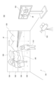
- FIG. 1 schematically shows an imaging system 500.
- This photographing system 500 is a system for photographing as a virtual production, and the drawing shows part of the equipment arranged in the photographing studio.
- a performance area 501 is provided in which performers 510 perform acting and other performances.
- a large display device is arranged at least on the back surface of the performance area 501, and further on the left and right sides and on the top surface.
- the device type of the display device is not limited, the drawing shows an example using an LED wall 505 as an example of a large display device.
- a single LED wall 505 forms a large panel by connecting and arranging a plurality of LED panels 506 vertically and horizontally.
- the size of the LED wall 505 referred to here is not particularly limited, but may be any size necessary or sufficient for displaying the background when the performer 510 is photographed.
- a required number of lights 580 are arranged at required positions such as above or to the side of the performance area 501 to illuminate the performance area 501 .
- a camera 502 is arranged for filming, for example, movies and other video content.
- the camera 502 can be moved by a cameraman 512, and can be operated to change the shooting direction, angle of view, and the like.
- the movement of the camera 502, the angle of view operation, and the like are performed by remote operation.
- the camera 502 may move or change the angle of view automatically or autonomously. For this reason, the camera 502 may be mounted on a camera platform or a moving object.
- the performer 510 in the performance area 501 and the video displayed on the LED wall 505 are captured together. For example, by displaying the scenery as the background image vB on the LED wall 505, it is possible to shoot the same image as when the performer 510 is actually acting in the place of the scenery.
- An output monitor 503 is arranged near the performance area 501 .
- the image captured by the camera 502 is displayed on the output monitor 503 in real time as a monitor image vM. This allows the director and staff who produce the video content to check the video being shot.
- the photography system 500 for photographing the performance of the performer 510 against the backdrop of the LED wall 505 in the photography studio has various advantages over greenback photography.
- post-production after shooting is more efficient than when shooting with a green screen. This is because there are cases where so-called chromakey synthesis can be made unnecessary, and there are cases where color correction and reflection synthesis can be made unnecessary. Also, even if chromakey synthesis is required at the time of shooting, the fact that there is no need to add a background screen also contributes to efficiency.
- the green tint does not increase, so the correction is unnecessary.
- the background image vB the reflection on the actual article such as the glass is naturally obtained and photographed, so there is no need to synthesize the reflection image.
- the background video vB will be explained with reference to FIGS. 2 and 3.
- FIG. Even if the background image vB is displayed on the LED wall 505 and photographed together with the performer 510, simply displaying the background image vB makes the background of the photographed image unnatural. This is because the background image vB is a two-dimensional image that is actually three-dimensional and has depth.
- the camera 502 can photograph the performer 510 in the performance area 501 from various directions, and can also perform a zoom operation.
- the performer 510 does not stop at one place either.
- the actual appearance of the background of the performer 510 should change according to the position, shooting direction, angle of view, etc. of the camera 502, but such a change cannot be obtained with the background image vB as a plane image. Therefore, the background image vB is changed so that the background, including the parallax, looks the same as it actually does.
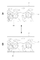
- FIG. 2 shows camera 502 photographing actor 510 from a position on the left side of the figure
- FIG. 3 shows camera 502 photographing actor 510 from a position on the right side of the figure.
- the shooting area image vBC is shown within the background image vB.
- a portion of the background image vB excluding the shooting area image vBC is called an "outer frustum”
- the shooting area image vBC is called an "inner frustum”.
- the background image vB described here refers to the entire image displayed as the background including the shooting area image vBC (inner frustum).
- the range of this shooting area image vBC corresponds to the range actually shot by the camera 502 within the display surface of the LED wall 505 .
- the photographing area image vBC becomes an image that has been deformed according to the position, photographing direction, angle of view, etc. of the camera 502 so as to express the scene that is actually seen when the position of the camera 502 is set as the viewpoint. ing.
- 3D background data which is a 3D (three dimensions) model as a background
- the 3D background data is sequentially rendered in real time based on the viewpoint position of the camera 502. do.
- the range of the shooting area image vBC is actually set to be slightly wider than the range shot by the camera 502 at that time. This is to prevent the image of the outer frustum from being reflected due to the drawing delay when the range to be photographed changes slightly due to panning, tilting, zooming, etc. of the camera 502. This is to avoid the influence of diffracted light.
- the image of the shooting area image vBC rendered in real time in this way is combined with the image of the outer frustum.
- the image of the outer frustum used in the background image vB is rendered in advance based on the 3D background data, and a part of the image of the outer frustum incorporates the image as the shooting area image vBC rendered in real time. Thus, the entire background image vB is generated.
- the output monitor 503 displays the monitor image vM including the performer 510 and the background, which is the captured image.
- the background of this monitor image vM is the shooting area image vBC.
- the background included in the captured image is a real-time rendered image.
- the background image vB is not only displayed two-dimensionally, but also the shooting area image is displayed so that the same image as when actually shooting on location can be shot. Background video vB including vBC is changed in real time.
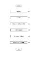
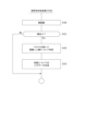
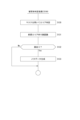
- the production process of video content as a virtual production that shoots with the shooting system 500 will be explained.
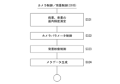
- the video content production process is roughly divided into three stages. They are asset creation ST1, production ST2, and post-production ST3.
- Asset creation ST1 is the process of creating 3D background data for displaying the background video vB.
- the background image vB is generated by performing real-time rendering using the 3D background data at the time of shooting. Therefore, 3D background data as a 3D model is created in advance.
- 3D background data production methods include full CG (Full Computer Graphics), point cloud data (Point Cloud) scanning, and photogrammetry.
- Full CG is a method of creating 3D models with computer graphics. Although this method requires the most man-hours and time among the three methods, it is suitable for use when an unrealistic image or an image that is actually difficult to shoot is desired to be used as the background image vB.
- LiDAR lidar
- 360-degree image is taken from the same position with a camera.
- This is a method of generating a 3D model from point cloud data by loading data. Compared to full CG, 3D models can be produced in a short time. In addition, it is easier to create a high-definition 3D model than photogrammetry.
- Photogrammetry is a technique of photogrammetry that analyzes parallax information and obtains dimensions and shapes from two-dimensional images obtained by photographing an object from multiple viewpoints. 3D model production can be done in a short time. Note that point group information acquired by the lidar may be used in generating 3D data by photogrammetry.
- these methods are used to create a 3D model that becomes 3D background data.
- the above methods may be used in combination.
- a part of a 3D model produced by point cloud data scanning or photogrammetry is produced by CG and synthesized.
- Production ST2 is the process of shooting in a shooting studio as shown in FIG. Elemental technologies in this case include real-time rendering, background display, camera tracking, and lighting control.
- Real-time rendering is a rendering process for obtaining a shooting area image vBC at each point in time (each frame of the background image vB) as described with reference to FIGS. This renders the 3D background data produced by the asset creation ST1 from a viewpoint corresponding to the position of the camera 502 at each time point.
- Camera tracking is performed to obtain shooting information from the camera 502, and tracks the position information, shooting direction, angle of view, etc. of the camera 502 at each point in time.
- Real-time rendering according to the viewpoint position of the camera 502 and the like can be executed by providing the rendering engine with shooting information including these corresponding to each frame.
- the shooting information is information linked or associated with video as metadata.
- the shooting information is assumed to include position information of the camera 502 at each frame timing, orientation of the camera, angle of view, focal length, F number (aperture value), shutter speed, lens information, and the like.
- Lighting control refers to controlling the state of lighting in the imaging system 500, specifically controlling the light intensity, emission color, lighting direction, etc. of the light 580. For example, lighting control is performed according to the time setting and location setting of the scene to be shot.
- Post-production ST3 indicates various processes performed after shooting. For example, video correction, video adjustment, clip editing, video effects, and the like are performed.
- Image correction may include color gamut conversion, color matching between cameras and materials, and the like. Color adjustment, brightness adjustment, contrast adjustment, etc. may be performed as image adjustment. As clip editing, clip cutting, order adjustment, time length adjustment, etc. may be performed. As a video effect, synthesis of CG video and special effect video may be performed.
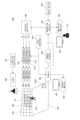
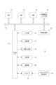
- FIG. 5 is a block diagram showing the configuration of the photographing system 500 outlined in FIGS. 1, 2, and 3. As shown in FIG.
- the imaging system 500 shown in FIG. 5 includes the LED wall 505 by the plurality of LED panels 506, camera 502, output monitor 503, and light 580 described above.
- the imaging system 500 further includes a rendering engine 520, an asset server 530, a sync generator 540, an operation monitor 550, a camera tracker 560, an LED processor 570, a lighting controller 581, and a display controller 590, as shown in FIG.
- the LED processor 570 is provided corresponding to each LED panel 506 and drives the corresponding LED panel 506 to display images.
- the sync generator 540 generates a synchronization signal for synchronizing the frame timing of the image displayed by the LED panel 506 and the frame timing of the imaging by the camera 502 and supplies it to each LED processor 570 and the camera 502 . However, this does not prevent the output from the sync generator 540 from being supplied to the rendering engine 520 .
- the camera tracker 560 generates shooting information by the camera 502 at each frame timing and supplies it to the rendering engine 520 .
- the camera tracker 560 detects the position of the LED wall 505 or relative position information of the camera 502 with respect to a predetermined reference position and the shooting direction of the camera 502 as one piece of shooting information, and supplies these to the rendering engine 520.
- a specific detection method by the camera tracker 560 there is a method of randomly arranging reflectors on the ceiling and detecting the position from reflected infrared light emitted from the camera 502 side.
- a detection method there is also a method of estimating the self-position of the camera 502 based on gyro information mounted on the platform of the camera 502 or the body of the camera 502 or image recognition of the image captured by the camera 502 .
- the angle of view, focal length, F number, shutter speed, lens information, etc. may be supplied from the camera 502 to the rendering engine 520 as shooting information.
- the asset server 530 is a server that stores the 3D model produced by the asset creation ST1, that is, the 3D background data in a recording medium, and can read out the 3D model as needed. That is, it functions as a DB (data Base) for 3D background data.
- DB data Base
- the rendering engine 520 performs processing for generating a background image vB to be displayed on the LED wall 505 . Therefore, the rendering engine 520 reads the necessary 3D background data from the asset server 530 . The rendering engine 520 then generates an image of the outer frustum used in the background image vB by rendering the 3D background data as viewed from the spatial coordinates specified in advance. In addition, the rendering engine 520, as a process for each frame, uses the shooting information supplied from the camera tracker 560 and the camera 502 to specify the viewpoint position and the like with respect to the 3D background data, and renders the shooting area video vBC (inner frustum). I do.
- the rendering engine 520 combines the shooting area video vBC rendered for each frame with the pre-generated outer frustum to generate the background video vB as video data for one frame.
- the rendering engine 520 then transmits the generated video data of one frame to the display controller 590 .
- the display controller 590 generates a divided video signal nD by dividing one frame of video data into video portions to be displayed on each LED panel 506 and transmits the divided video signal nD to each LED panel 506 .
- the display controller 590 may perform calibration according to individual differences/manufacturing errors such as color development between display units. Note that these processes may be performed by the rendering engine 520 without providing the display controller 590 . That is, the rendering engine 520 may generate the divided video signal nD, perform calibration, and transmit the divided video signal nD to each LED panel 506 .
- Each LED processor 570 drives the LED panel 506 based on the received divided video signal nD to display the entire background video vB on the LED wall 505 .
- the background image vB includes the shooting area image vBC rendered according to the position of the camera 502 at that time.
- the camera 502 can capture the performance of the performer 510 including the background image vB displayed on the LED wall 505 in this way.
- the image captured by the camera 502 is recorded on a recording medium inside the camera 502 or by an external recording device (not shown), and is also supplied to the output monitor 503 in real time and displayed as a monitor image vM.
- An operation image vOP for controlling the rendering engine 520 is displayed on the operation monitor 550 .
- the engineer 511 can perform necessary settings and operations regarding rendering of the background video vB while viewing the operation image vOP.
- a lighting controller 581 controls the emission intensity, emission color, irradiation direction, and the like of the light 580 .
- the lighting controller 581 may, for example, control the lights 580 asynchronously with the rendering engine 520, or may control them in synchronization with the shooting information and rendering processing. Therefore, the lighting controller 581 may perform light emission control according to instructions from the rendering engine 520 or a master controller (not shown).
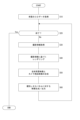
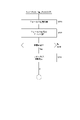
- FIG. 6 shows a processing example of the rendering engine 520 in the photographing system 500 having such a configuration.
- the rendering engine 520 reads the 3D background data to be used this time from the asset server 530 in step S10, and develops it in an internal work area. Then, an image to be used as an outer frustum is generated.
- the rendering engine 520 repeats the processing from step S30 to step S60 at each frame timing of the background video vB until it determines in step S20 that the display of the background video vB based on the read 3D background data has ended.
- step S30 the rendering engine 520 acquires shooting information from the camera tracker 560 and the camera 502. This confirms the position and state of the camera 502 to be reflected in the current frame.
- step S40 the rendering engine 520 performs rendering based on the shooting information. That is, rendering is performed by specifying the viewpoint position for the 3D background data based on the position of the camera 502 to be reflected in the current frame, the shooting direction, the angle of view, or the like. At this time, image processing reflecting focal length, F number, shutter speed, lens information, etc., can also be performed. By this rendering, video data as the shooting area video vBC can be obtained.
- the rendering engine 520 performs a process of synthesizing the outer frustum, which is the overall background image, and the image reflecting the viewpoint position of the camera 502, that is, the shooting area image vBC. For example, it is a process of synthesizing an image generated by reflecting the viewpoint of the camera 502 with an image of the entire background rendered from a specific reference viewpoint. As a result, the background image vB of one frame displayed on the LED wall 505, that is, the background image vB including the shooting area image vBC is generated.
- step S60 The processing of step S60 is performed by the rendering engine 520 or the display controller 590.
- the rendering engine 520 or the display controller 590 generates a divided video signal nD that divides the one-frame background video vB into videos displayed on individual LED panels 506.
- FIG. Calibration may be performed.
- each divided video signal nD is transmitted to each LED processor 570 .
- the background image vB including the shooting area image vBC captured by the camera 502 is displayed on the LED wall 505 at each frame timing.
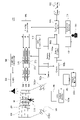
- FIG. 7 shows a configuration example when a plurality of cameras 502a and 502b are used.
- the cameras 502a and 502b are configured to be able to take pictures in the performance area 501 independently.
- Each camera 502 a , 502 b and each LED processor 570 are also kept synchronized by a sync generator 540 .
- Output monitors 503a and 503b are provided corresponding to the cameras 502a and 502b, and are configured to display images captured by the corresponding cameras 502a and 502b as monitor images vMa and vMb.
- camera trackers 560a and 560b are provided corresponding to the cameras 502a and 502b, and detect the positions and shooting directions of the corresponding cameras 502a and 502b, respectively.
- the shooting information from the camera 502 a and the camera tracker 560 a and the shooting information from the camera 502 b and the camera tracker 560 b are sent to the rendering engine 520 .
- the rendering engine 520 can perform rendering to obtain the background video vB of each frame using the shooting information on either the camera 502a side or the camera 502b side.
- FIG. 7 shows an example using two cameras 502a and 502b, it is also possible to use three or more cameras 502 for shooting.
- a plurality of cameras 502 there is a situation that the shooting area images vBC corresponding to the respective cameras 502 interfere with each other.
- the shooting area image vBC corresponding to the camera 502a is shown. will also be needed. If each shooting area image vBC corresponding to each camera 502a, 502b is simply displayed, they interfere with each other. Therefore, it is necessary to devise a way to display the shooting area image vBC.
- the information processing device 70 is a device such as a computer device capable of information processing, particularly video processing.
- the information processing device 70 is assumed to be a personal computer, a workstation, a mobile terminal device such as a smart phone or a tablet, a video editing device, or the like.
- the information processing device 70 may be a computer device configured as a server device or an arithmetic device in cloud computing.
- the information processing device 70 can function as a 3D model creation device that creates a 3D model in the asset creation ST1.
- the information processing device 70 can also function as a rendering engine 520 that configures the shooting system 500 used in the production ST2.
- the information processing device 70 can also function as an asset server 530 .
- the information processing device 70 can also function as a video editing device that performs various video processing in the post-production ST3.
- the RAM 73 also appropriately stores data necessary for the CPU 71 to execute various processes.
- the video processing unit 85 is configured as a processor that performs various video processing. For example, it is a processor that can perform one or more of 3D model generation processing, rendering, DB processing, video editing processing, and the like.
- the video processing unit 85 can be implemented by, for example, a CPU separate from the CPU 71, a GPU (Graphics Processing Unit), a GPGPU (General-purpose computing on graphics processing units), an AI (artificial intelligence) processor, or the like. Note that the video processing unit 85 may be provided as a function within the CPU 71 .
- the CPU 71 , ROM 72 , RAM 73 , nonvolatile memory section 74 and video processing section 85 are interconnected via a bus 83 .
- An input/output interface 75 is also connected to this bus 83 .
- the input/output interface 75 is connected to an input section 76 including operators and operating devices.
- various operators and operation devices such as a keyboard, mouse, key, dial, touch panel, touch pad, remote controller, etc. are assumed.
- a user's operation is detected by the input unit 76 , and a signal corresponding to the input operation is interpreted by the CPU 71 .
- a microphone is also envisioned as input 76 .
- a voice uttered by the user can also be input as operation information.
- the input/output interface 75 is connected integrally or separately with a display unit 77 such as an LCD (Liquid Crystal Display) or an organic EL (electro-luminescence) panel, and an audio output unit 78 such as a speaker.
- the display unit 77 is a display unit that performs various displays, and is configured by, for example, a display device provided in the housing of the information processing device 70, a separate display device connected to the information processing device 70, or the like.
- the display unit 77 displays various images, operation menus, icons, messages, and the like on the display screen based on instructions from the CPU 71, that is, as a GUI (Graphical User Interface).
- GUI Graphic User Interface
- the input/output interface 75 may be connected to a storage section 79 and a communication section 80, each of which is composed of a HDD (Hard Disk Drive), a solid-state memory, or the like.
- a HDD Hard Disk Drive
- a solid-state memory or the like.
- the storage unit 79 can store various data and programs.
- a DB can also be configured in the storage unit 79 .
- the storage unit 79 can be used to construct a DB that stores 3D background data groups.
- the communication unit 80 performs communication processing via a transmission line such as the Internet, and communication with various devices such as an external DB, editing device, and information processing device through wired/wireless communication, bus communication, and the like.
- the communication unit 80 can access the DB as the asset server 530 and receive shooting information from the camera 502 and camera tracker 560 .
- the information processing device 70 used in the post-production ST3 it is possible to access the DB as the asset server 530 through the communication section 80.
- a drive 81 is also connected to the input/output interface 75 as required, and a removable recording medium 82 such as a magnetic disk, optical disk, magneto-optical disk, or semiconductor memory is appropriately loaded.
- Video data and various computer programs can be read from the removable recording medium 82 by the drive 81 .
- the read data is stored in the storage unit 79 , and video and audio contained in the data are output from the display unit 77 and the audio output unit 78 .
- Computer programs and the like read from the removable recording medium 82 are installed in the storage unit 79 as required.
- software for the processing of the present embodiment can be installed via network communication by the communication unit 80 or via the removable recording medium 82.
- the software may be stored in advance in the ROM 72, the storage unit 79, or the like.
- Control processing of the information processing apparatus 70 of the present embodiment that can be applied to virtual production will be described.
- the image captured by the camera 502 in the above virtual production imaging system 500 is referred to as "captured image vC".
- the range of the subject included in the image of the captured image vC is the same as that of the monitor image vM.
- the captured image vC is obtained by capturing an object such as the performer 510 and the background image vB of the LED wall 505 by the camera 502 .
- the background area ARb and the foreground area ARf can be separated from the captured image vC using the mask information (mask MK in FIG. 10 described later).
- the background area ARb is an area within the captured image vC in which the background image vB is displayed.
- the photographing area image vBC in the background image vB is actually reflected in the photographed image vC.
- the foreground area ARf is an area within the image in which the foreground object is shown in the captured image vC. For example, it is a region in which a person as the performer 510 or an object that actually exists is displayed.
- the background image vB reflected in the captured image vC is obtained by photographing the image displayed on the LED wall 505 .
- the image displayed and captured on the display device in this way will be referred to as a display image vD.
- the image of the background area ARb in the captured image vC is this display image vD.
- the image of the object reflected in the shot image vC is a shot of an existing object such as a performer. For the sake of explanation, this is called an object image vOB. That is, the image of the foreground area ARf is the object image vOB.
- the mask MK can be used to separate the background area ARb and the foreground area ARf for the captured image vC. , object video vOB.
- the area of the display image vD and the area of the object image vOB can be determined within one screen (within one frame) of the captured image vC.
- control relating to generation of the camera 502 and the background image vB is performed based on such determination.
- the background of such control will be described.
- the background image vB not only scenery such as nature and buildings but also people and articles may be displayed.
- a volumetric imaging technique there is also a technique for converting a real person or place into three-dimensional digital data and reproducing it with high image quality.
- a person can be photographed three-dimensionally and handled as a CG image. If this is used to generate a background image vB in virtual production, a person may be included in the background image vB.
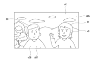
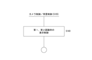
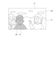
- the captured image vC in FIG. 9 includes an object image vOB as an image of a real performer 510 and a person image as a display image vD. If the camera 502 performs face recognition by image analysis, both the face image 60 as the object video vOB and the face image 61 as the display video vD are determined to be face images.
- the camera 502 recognizes a face as a subject and displays the face recognition frame 62 on the monitor, the face recognition frame 62 is displayed on both the face images 60 and 61 as in the camera monitor video vCM of FIG. I will display it.
- the camera monitor image vCM in FIG. 10 is an image in which the subject being photographed by the camera 502 is displayed on a viewfinder or other monitor device. It may be considered as the monitor image vM described above.
- a cameraman, an operator, or the like can know, for example, the object recognition result of the camera 502 by looking at the camera monitor image vCM, but in this case, it is not possible to know who is a real person from the camera monitor image vCM alone.
- the focus operation may be performed with the recognized subject as the focus target.
- the face recognition frame 62 is displayed as shown in FIG. 10
- the camera 502 determines that both of them are human faces, and therefore tries to perform focus control on both of the face images 60 and 61 . For this reason, when shooting a virtual production, a cameraman or the like can determine whether the focus is on an existing subject or whether the subject displayed on the LED wall 505 (virtual person, article, etc.) is in focus. There is a need to.
- the camera 502 cannot distinguish between the real person and the virtual person on the captured image vC, so the display operation and the AF operation are not optimal. There are some things that are difficult.
- the background area ARb (display image vD) and the foreground area ARf (object image vOB) are clearly determined using the mask MK for the captured image vC. Then, the camera 502 and the generation of the background image vB are controlled according to the determination result.
- a mask MK as shown in FIG. 11 is generated for one frame of the captured image vC as shown in FIG. This becomes information for separating the area of the photographed object and the area of the image of the LED wall 505 within one frame of the photographed image vC.
- the information processing device 70 as the rendering engine 520 applies the mask MK shown in FIG. 11 to the frame of the shot video vC shown in FIG. Whether or not it is the display image vD is determined, and the camera 502 is caused to perform appropriate display or AF operation, or to control the generation of the background image vB. Specific processing examples will be described later as first, second, and third embodiments.
- a SWIR (Short Wavelength Infra-Red) camera infrared short wavelength camera
- the SWIR camera it is possible to separate the image of the LED wall 505 where the light source changes drastically and the image of the foreground subject.
- FIG. 12A shows the wavelength bands that can be captured by each of the RGB camera, SWIR camera, and IR camera (infrared camera).
- An RGB camera is a camera that captures visible light in a wavelength band from 380 nm to 780 nm, for example.
- An RGB camera is usually used as the camera 502 for obtaining the captured image vC.
- the IR camera is a camera that captures near-infrared light from 800 nm to 900 nm.
- SWIR cameras include, for example, the following types (a), (b), and (c).
- (c) A camera capable of photographing a wavelength band of around 1150 nm (with a front-to-back tolerance) are just examples.
- a SWIR camera covers a wider wavelength band than an IR camera, and cameras capable of photographing in a wavelength band from 400 nm to 1700 nm, for example, are commercially available.
- FIG. 12B shows the quantum efficiency for each wavelength of the commercially available SWIR camera. As shown, high quantum efficiency is achieved in the range from 400 nm to 1700 nm. That is, since the wavelength bands of (b) and (c) can be covered, a SWIR camera having characteristics as shown in FIG. 12B can be applied.
- part of the light 580 is used to irradiate an object such as the performer 510 with infrared rays, and the object is photographed by the SWIR camera.
- the image on the LED wall 505 is not reflected and becomes a black image, and the performer 510 and the like reflect infrared light, and some brightness is observed. Therefore, by determining the brightness difference in the frame in the image captured by the SWIR camera, it is possible to generate a mask MK that extracts only the object with high accuracy.
- a SWIR camera can appropriately detect the range of a person including hair. Hair is less reflective than skin, but it is effective to cover a high wavelength band for detection of the hair region. For example, with a camera capable of photographing near 1150 nm as in (c) above, the reflectance of human hair and the reflectance of human skin are equivalent. However, the reflectance of hair differs depending on gender and race (black hair, blond hair, etc.), and it changes depending on whether the hair is dyed or not. By integrating the band and shooting, the brightness of the skin and hair becomes equal, and the range of the head can be clearly determined.
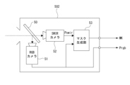
- the camera 502 is configured as shown in FIG.
- An RGB camera 51 and a SWIR camera 52 are arranged in a unit as one camera 502 .
- the beam splitter 50 splits the incident light so that the incident light enters the RGB camera 51 and the SWIR camera 52 with the same optical axis.
- the RGB camera 51 outputs an image Prgb that is used as the captured image vC.
- the SWIR camera 52 outputs an image Pswir for generating the mask MK.
- the camera 502 By configuring the camera 502 as a coaxial camera including the RGB camera 51 and the SWIR camera 52 in this way, parallax does not occur between the RGB camera 51 and the SWIR camera 52, and the image Prgb and the image Pswir are identical to each other. The timing, the same angle of view, and the same field of view range can be obtained.
- Mechanical position adjustment and optical axis alignment using a calibration image are performed in advance in a unit as the camera 502 so that the optical axes are aligned. For example, an image for calibration is captured, feature points are detected, and alignment processing is performed in advance. Even if the RGB camera 51 uses a high-resolution camera for producing high-definition video content, the SWIR camera 52 does not need to have a high resolution as well.
- the SWIR camera 52 may be of any type as long as it can extract an image whose imaging range matches that of the RGB camera 51 . Therefore, the sensor size and image size are not limited to those that match those of the RGB camera 51 .
- the RGB camera 51 and the SWIR camera 52 should be synchronized in frame timing. Further, according to the zoom operation of the RGB camera 51, the SWIR camera 52 may also be zoomed or the cropping range of the image may be adjusted.
- SWIR camera 52 and the RGB camera 51 may be arranged in stereo. This is because parallax does not matter if the subject does not move in the depth direction. Also, a plurality of SWIR cameras 52 may be used.
- the image Prgb and the image Pswir are supplied to the rendering engine 520 .
- the rendering engine 520 having the configuration in FIG. 8 uses the image Pswir in the image processing unit 85 to generate the mask MK.
- the rendering engine 520 uses the image Prgb as the captured image vC.
- the image processing unit 85 determines the background area ARb and the foreground area ARf using the mask MK for each frame of the image Prgb, and performs necessary control processing and After performing image processing, the captured image vC can be recorded on a recording medium.
- the captured image vC is stored in the storage unit 79 . Alternatively, it can be transferred to the asset server 530 or other external device for recording.
- FIG. 14 shows another configuration example of the camera 502.
- the mask generator 53 can be composed of, for example, a video processor.
- a mask generator 53 receives the image Pswir from the SWIR camera 52 and generates a mask MK. Note that when adjusting the clipping range from the image Pswir when generating the mask MK, the mask generation unit 53 also inputs and refers to the image Prgb from the RGB camera 51 .
- the image Prgb and the mask MK are supplied to the rendering engine 520.
- the rendering engine 520 can then obtain the mask MK and use the mask MK to separate the background area ARb and the foreground area ARf for each frame of the video Prgb.
- part of the shooting information is supplied from the camera 502 to the rendering engine 520 as described above, although not shown.
- the angle of view, focal length, F-number (aperture value), shutter speed, lens information, camera direction, etc. as shooting information are supplied from the camera 502 to the rendering engine 520 as information relating to the RGB camera 51 .
- the position information of the camera 502 detected by the camera tracker 560, the direction of the camera, and the like are also supplied to the rendering engine 520 as shooting information.
- First Embodiment> A specific processing example will be described below. As a first embodiment, an example will be given in which the rendering engine 520 controls display of the camera monitor video vCM by the camera 502 at the time of shooting. The configuration of FIG. 13 is assumed as the camera 502 below.
- FIG. 15 shows control processing that the rendering engine 520 performs for each frame of the shot video vC.
- the rendering engine 520 renders the shooting area image vBC for each frame in order to generate the background image vB to be displayed on the LED wall 505 .
- the rendering engine 520 performs the processing of FIG. 15 for each frame of the captured image vC captured by the camera 502 .
- step S101 the rendering engine 520 acquires video. That is, one frame of captured video vC transmitted from the camera 502 is processed. Specifically, the rendering engine 520 processes one frame of video Prgb and video Pswir transmitted from the camera 502 . At the same time, the rendering engine 520 also acquires shooting information transmitted from the camera 502 and camera tracker 560 corresponding to the frame.
- the rendering engine 520 generates a mask MK to be applied to the current frame. That is, the rendering engine 520 uses the image Pswir to generate the mask MK as described above.
- step S103 the rendering engine 520 uses the mask MK generated in step S102 to identify the background area ARb and the foreground area ARf of the captured image vC of the currently acquired frame, that is, the image Prgb. That is, the area of the display image vD and the area of the object image vOB are specified in the frame.
- step S104 the rendering engine 520 performs subject determination processing.
- 16 and 17 show an example of performing face recognition as subject determination processing.
- the rendering engine 520 performs face recognition processing within the current frame in step S120. If no face is detected in the frame, the subject determination process ends from step S121.
- the rendering engine 520 proceeds from step S121 to step S122 and uses the mask MK to determine whether it is the display image vD or the object image vOB for each recognized face. It is determined whether or not The rendering engine 520 compares the coordinates of the area recognized as a face in the frame with the coordinates of the background area ARb and the foreground area ARf indicated by the mask MK, thereby determining whether each recognized face is the display image vD. It can be determined whether it is an object image vOB.
- step S123 the rendering engine 520 generates metadata according to the determination result for each face.
- positional information of a face within a frame, information as to whether the face is the display image vD or the object image vOB, etc. are used as metadata.
- the example of FIG. 17 is an example of recognizing only the face as the object video vOB.
- the rendering engine 520 uses the mask MK to perform area determination within the current frame. Specifically, the range of the foreground area ARf is determined. Then, in step S131, the rendering engine 520 performs face recognition processing within the foreground area ARf. If the face is not recognized, the subject determination process ends from step S132.
- step S132 If one or more faces are recognized within the foreground area ARf, the rendering engine 520 proceeds from step S132 to step S133 to generate metadata for each face.
- position information of a face within a frame, information indicating that the face is an object video vOB, and the like are used as metadata.
- step S105 is for controlling the camera 502 or controlling the generation processing of the background image vB in the rendering engine 520.
- FIG. In this first embodiment, an example of controlling the display and focus operation of the camera 502 will be given.
- the rendering engine 520 performs, for example, the processes of FIGS. 18 and 19.
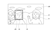
- step S140 the rendering engine 520 performs display control of the subject recognition frame based on the subject determination processing of FIG. Specifically, as shown in FIG. 20, display control of a first recognition frame 64 and a second recognition frame 65 is performed for face images 60 and 61 .
- the recognition frame in this example is the recognition frame of the face image within the captured video vC.
- the first recognition frame 64 is a face recognition frame as the object image vOB
- the second recognition frame 65 is a face recognition frame as the display image vD.
- the first recognition frame 64 is indicated by a solid line
- the second recognition frame 65 is indicated by a broken line. , the shape, etc. are displayed differently.
- the rendering engine 520 performs the control processing in step S140, according to the result of subject determination (face recognition), for position information about each recognized face and information indicating whether it is the display image vD or the object image vOB. to the camera 502 to instruct display of the recognition frame.
- the camera 502 displays both or one of the first recognition frame 64 and the second recognition frame 65 on the camera monitor image vCM based on the supplied information.
- the first recognition frame 64 and the second recognition frame 65 are displayed in different modes as shown in FIG.
- the rendering engine 520 may instruct the camera 502 on the display mode and display position of the frames as the first recognition frame 64 and the second recognition frame 65 .
- first recognition frame 64 and the second recognition frame 65 are displayed in different manners on the camera monitor video vCM, the cameraman, operator, and the like can easily understand whether each face image is the object video vOB or the display video vD. Shooting and various operations can be performed while clearly recognizing whether there is.
- the display mode of the face image itself may be changed.
- the face of the object image vOB may remain normal, and the face of the display image vD may be made monochrome (grayscale), specified in a specific color, or reduced in luminance.
- the display mode should be different so that the face image is the display image vD or the object image vOB can be distinguished.
- the example of FIG. 19 is an example in which focus operation control is performed in addition to the recognition frame display control as the first recognition frame 64 and the second recognition frame 65 as described above.
- the rendering engine 520 controls the display of the first recognition frame 64 and the second recognition frame 65 as described above. Control is performed to instruct the AF operation so that the focus operation is performed.
- the camera 502 may start the AF operation with the subject in the first recognition frame 64 as the target in response to receiving the position information as the first recognition frame 64 .
- the above control in FIGS. 20 and 21 is an example of recognizing a face image, but the above processing can be applied not only to the face image but also to the case of recognizing any subject such as an animal or an article.
- the mask MK may be transmitted to the camera 502 and the camera monitor image vCM may be displayed according to the mask MK.
- FIG. 22 shows an example in which the range defined by the mask MK as the foreground area ARf and the range defined as the background area ARb are displayed differently.
- the foreground area display 66 is displayed with higher luminance than the background area display 67 so as to stand out from the display image vD.
- the foreground area display 66 may be displayed in color and the background area display 67 may be displayed in monochrome. That is, the foreground area display 66 and the background area display 67 may be displayed in different manners so that the area distinction as the mask MK can be recognized.
- the rendering engine 520 After completing the control processing of each of the above examples in step S105 of FIG. 15, the rendering engine 520 performs video recording in step S106. That is, the current frame is recorded on the recording medium as one frame data of the captured image vC.
- the metadata generated in step S123 of FIG. 16 and step S133 of FIG. 17 are also recorded in association with the frame. For example, the face position information in the frame and information indicating whether the face image is the display image vD or the object image vOB.
- the mask MK generated in the current frame may be recorded as metadata.
- the control parameters instructed to the camera 502 in step S105 may be recorded as metadata.
- Second Embodiment> As a second embodiment, an example will be described in which the process of generating the background image vB and the control process of the focus operation of the camera 502 are performed according to the area determination of the focus position. A processing example of the second embodiment can also be explained with reference to FIG. 23 and 24 as the control processing in step S105.
- step S105 the generation processing of the background image vB is controlled according to the focus position of the camera 502.
- the rendering engine 520 acquires the current focus position of the camera 502 in step S201.
- the current focal length may be acquired.
- step S202 the rendering engine 520 determines the subject to be focused from the current focal length and information on the subject determined by the subject determination in step S104, and uses the mask MK to determine the area of the subject. conduct. This can be said to be processing for determining whether the focused subject is a real object or the background image vB of the LED wall 505 .
- the rendering engine 520 determines a subject to be focused in the frame, that is, a subject in focus. Then, by comparing the position of the subject within the frame with the mask MK, it is possible to determine whether the subject to be focused is the display image vD or the object image vOB.
- the rendering engine 520 acquires the position information of the camera 502 at the time of each frame and the information of the shooting direction from the camera 502 or the camera tracker 560 as the shooting information described above. Therefore, the positional relationship between the position and shooting direction of the camera 502 and the LED wall 505 can be grasped at the time of each frame. Therefore, by obtaining the focal length, it is possible to determine whether the focus is on the object or on the LED wall 505 . Alternatively, it can be determined that the focus target is gradually changing from the object to the LED wall 505, or vice versa. Such determination may be used together.
- step S ⁇ b>203 the rendering engine 520 branches the processing depending on whether the focus target is the background image vB, that is, the display image vD of the LED wall 505 . If the focus target is the actual object and not the background image vB, the rendering engine 520 proceeds to step S205 to perform defocus control on the background image vB. That is, the background image vB (capturing area image vBC) generated by rendering is given a defocus effect.
- the defocus amount in this case may be a fixed amount, but as a variable amount determined according to the distance between the position (focused position) in the performance area 501 obtained from the focal length at that time and the LED wall 505 good too.
- the captured image vC becomes an image in which the background is blurred and the object image vOB is conspicuous, for example, as shown in FIG. 25A.
- the rendering engine 520 proceeds to step S204 and performs focus control on the background image vB. That is, the background image vB to be generated is controlled so as to be a focused image without blurring. With such control, the captured image vC becomes an image in which the background is in focus, as shown in FIG. 25B, for example. Since the object image vOB is not actually focused by the camera 502, it becomes a blurred image.
- various focus states can be expressed for the background image vB as well. For example, when there are both a face image as an object video vOB and a face image as a display video vD in the captured video vC, it may be necessary to focus on a person in the background video vB or to focus on the person in the object video vOB. , and the person in the display image vD can be alternately focused.
- the focus target is gradually changed from the object image vOB to the display image vD.
- video expression is also realized.
- the rendering engine 520 uses the focus/defocus control parameters for the background video vB as metadata when recording in step S106. , may be recorded in association with the frame.
- the rendering engine 520 performs steps S201 and S202 in FIG. 24 as step S105 in FIG. 15 in the same manner as in FIG. 23 above. Then, in step S210, the rendering engine 520 confirms whether or not the current focus position is near the background.
- the vicinity of the background here can be defined as being within a predetermined distance from the surface of the LED wall 505 .
- the depth distance of the object image vOB that is the farthest from the camera 502 at that time point+a predetermined value may be used. That is, it is possible to detect a state in which the focal position is closer to the LED wall 505 on the back side than the object image vOB. Alternatively, it may be determined that the focus position is near the background when the focus target shifts to the range of the display image vD in the frame by the mask MK.
- step S203 If it is determined that the background is near, the process proceeds from step S203 to step S211, and the rendering engine 520 instructs the camera 502 to limit focus. This is a control that restricts focusing beyond that distance.
- the processing example of FIG. 24 controls to limit the movement of the focus position of the camera 502 to the LED wall 505 side of the object.
- the focus control of the camera 502 is always performed on the real object, and the background image vB is never focused.
- Such control is also useful in cases where it is desired to avoid performing AF operations on a subject recognized within the display image vD.
- processing in FIGS. 23 and 24 is the processing in step S105 in FIG. 15, the processing in FIGS. 23 and 24 may be performed together with the processing in FIG. 18 and FIG. Further, when performing the processing of FIGS. 23 and 24, there may be a processing example in which the subject determination processing of step S104 of FIG. 15 is not performed.
- Third Embodiment> As a third embodiment, an example of controlling parameters relating to the shooting operation of the camera 502 at the time of shooting will be given. Here, an example of controlling the F value, shutter speed, and ISO gain as exposure control parameters will be described.
- the processing example of the third embodiment can also be explained with reference to FIG. 15, and the processing shown in FIGS. 26 and 27 as the control processing of step S105 is performed as an example.
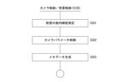
- the rendering engine 520 instructs the exposure control parameter of the camera 502 in accordance with the brightness of the captured image vC in the control processing of step S105.
- the rendering engine 520 measures the in-plane brightness of the foreground area ARf for the current frame in step S301.
- This is, for example, the average value of the luminance values of all pixels in the range defined as the foreground area ARf by the mask MK. Alternatively, it may be a peak value or a centroid value. Alternatively, instead of all pixels in the foreground area ARf, an average value of pixels having a high luminance value equal to or higher than a predetermined value may be used.
- step S302 the rendering engine 520 controls any one of the F number, shutter speed, and ISO gain for the camera 502, or a plurality of these parameters. That is, based on the in-plane luminance of the foreground area ARf measured in step S301, exposure control of the camera 502 is performed so that the luminance of the object image vOB in the foreground area ARf is in an appropriate state.
- step S303 the rendering engine 520 uses the control parameters sent to the camera 502 as metadata.
- the rendering engine 520 After performing the above processing of FIG. 26 in step S105 of FIG. 15, the rendering engine 520 records the frames of the shot video vC in step S106, and associates the metadata including the control parameters in step S302 with the frames. to record. By recording these metadata in association with frames, exposure parameters for each frame can be determined during video processing at a later point in time, and processing can be performed accordingly.
- the exposure amount of the camera 502 can be appropriately and automatically controlled according to the luminance state of the object image vOB. become.
- the rendering engine 520 measures the in-plane luminance of the foreground area ARf and the in-plane luminance of the background area ARb for the current frame.
- the in-plane luminance of the foreground area ARf is the average value, peak value, centroid value, etc. of the luminance values of all pixels (or part of the pixels) in the range defined as the foreground area ARf by the mask MK, as described above.
- the in-plane brightness of the background area ARb is the average value, peak value, centroid value, or the like of the brightness values of all pixels or some pixels in the range defined as the background area ARb by the mask MK.
- step S ⁇ b>322 the rendering engine 520 controls one of the F number, shutter speed, ISO gain, or a plurality of parameters for the camera 502 . Also, in step S323, the rendering engine 520 controls the luminance value of the background image vB (capturing area image vBC) to be rendered.
- the controls in steps S322 and S323 adjust the exposure of the camera 502 and adjust the luminance of the background image vB according to the in-plane luminance of the foreground area ARf and the in-plane luminance of the background area ARb measured in step S321. become a thing.
- the display image vD may be overexposed.
- the background image vB may be too bright, and the exposure adjustment of the camera 502 may make the object image vOB too dark.
- the background image vB may be too dark and the subject may also be dark, requiring additional lighting in the studio. Therefore, the in-plane luminance value is measured so that the object image vOB and the display image vD in the captured image vC have natural brightness, and the exposure amount of the camera 502 and the luminance of the background image vB are adjusted according to the luminance value. to do.
- step S324 the rendering engine 520 uses the control parameters sent to the camera 502 and the control parameters of the background video vB as metadata.
- the rendering engine 520 After performing the above processing of FIG. 27 in step S105 of FIG. 15, the rendering engine 520 records the frames of the shot video vC in step S106, and associates the metadata including the control parameters in step S303 with the frames. to record. By recording these metadata in association with frames, it is possible to determine the exposure parameter and the brightness parameter of the background image vB for each frame during video processing at a later time, and perform processing accordingly. can.
- the brightness of the captured display video vD and object video vOB is adjusted, and a captured video vC in which the foreground and background have natural brightness can be obtained.
- FIGS. 26 and 27 is the processing of step S105 of FIG. 15, but the processing of FIGS. good. 26 and 27, a processing example in which the subject determination processing in step S104 of FIG. 15 is not performed is also conceivable. Further, in FIG. 27, a processing example may be considered in which only the background image vB in step S323 is controlled without performing the processing in step S322.
- An example of instructing an exposure control parameter as a parameter of the camera 502 has been given, but it is also possible to perform camera control such as instructing the camera 502 of a shooting mode suitable for a scene according to subject determination processing, for example.
- Shooting modes include, for example, portrait mode, landscape mode, night view mode, and sunset mode. It is a moving object mode and the like.
- it is possible to determine whether it is an object image vOB or a display image vD by the mask MK it is possible to control the shooting mode according to the subject type of the object image, or shoot according to the scene of the display image vD (background image vB). mode can be controlled.
- Example of camera for mask generation> the SWIR camera 52 is used to generate the mask MK, but a device other than the SWIR camera 52 may be used to generate the mask MK for specifying the area of the subject that actually exists. .
- a depth camera such as Kinect or LiDAR, or a ToF (Time of Flight) sensor can be used to measure the depth of the subject, and the mask MK can be generated by separating the distance difference between the subject and the background LED.
- Kinect Kinect
- LiDAR LiDAR
- ToF Time of Flight
- thermography camera can be used to separate a subject using a person's body temperature and generate a mask MK.
- FIG. 28A is an example in which an LED wall 505 is provided including the floor portion in the performance area 501.
- LED walls 505 are provided on the rear surface, left side surface, right side surface, and floor surface.
- FIG. 28B shows an example in which LED walls 505 are provided on the top surface, back surface, left side surface, right side surface, and floor surface so as to surround the performance area 501 like a box.
- FIG. 26C is an example in which a cylindrical inner wall-shaped LED wall 505 is provided.
- the LED wall 505 has been used as the display device, and the displayed display image has been the background image obtained by rendering the 3D background data.
- the background area ARb as an example of the display image area and the foreground area ARf as an example of the object image area in the photographed image vC can be separated for image processing.
- the technology of the present disclosure can be applied without being limited to such a background/foreground relationship.
- FIG. 28D shows an example in which the display device 515 is arranged side by side with other subjects.
- a remote performer is displayed on the display device 515 and photographed together with the performer actually in the studio.
- the captured image includes both the display image and the object image.
- the mask MK can be used to separate the display image area and the object image area, so the processing of the embodiment can be similarly applied.
- the captured image includes the image of the display device and the image of the object that actually exists, these areas are distinguished and various image processing is performed.
- the technology of the present disclosure can be applied in some cases.
- the information processing apparatus 70 of the embodiment uses a mask MK to determine an object image vOB and a display image vD from a display image (for example, a background image vB) of a display device and a captured image vC obtained by capturing an object.
- a video processing unit 85 for processing is provided.
- the mask MK is used to determine the object image area (for example, the foreground area ARf) and the display image area (for example, the background area ARb) in the captured image vC, and the object image is determined to be either the object image vOB or the display image vD. Determine whether it is
- control can be performed according to the determination result of whether the object or area to be controlled is the display image vD or the object image vOB.
- the LED wall 505 is used as the display device, and the displayed display image vD is the background image vB obtained by rendering 3D background data.
- the photographed image vC is assumed to be an image obtained by photographing an object such as a performer 510 or an article against the backdrop of the LED wall 505 displaying the background image vB.
- each frame of the photographed image vC includes a background area ARb in which the background image vB is projected and a foreground area in which an object such as a performer 510 or an object is projected. ARf will be included.
- the background area ARb and the foreground area ARf are different in that the object being photographed is the displayed image and the actual object, so there are appropriate controls for each of them.
- the background area ARb and the foreground area ARf in the captured image vC can be distinguished from each other. It is possible to perform control suitable for the area to be controlled and the subject. As a result, appropriate control can be realized when video production is performed as virtual production, and video production that makes the most of the advantages of virtual production can be promoted.
- the image processing unit 85 performs, as the determination process, a process of determining whether the subject recognized by the subject determination in the captured image vC is the object image vOB or the display image vD. mentioned.
- a process of determining whether the subject recognized by the subject determination in the captured image vC is the object image vOB or the display image vD is the object image vOB or the display image vD.
- control suitable for the recognized face image can be performed. It can be performed.
- Recognition processing is not limited to face images. Various subjects are assumed, such as human faces, human bodies, body parts such as hands and feet, animal faces and body objects, artificial objects, and natural objects. Appropriate control becomes possible by determining whether it is the display image vD or the object image vOB when these subjects are recognized.
- the image processing unit 85 determines an object image area (foreground area ARf) in which the object image vOB is projected within the captured image vC as the determination processing, and performs subject determination within the object image area.
- the foreground area ARf is determined within the captured image vC
- the face image recognition processing is performed within the foreground area ARf.
- recognition processing is not limited to face images.
- the background area ARb may be determined as the display image area in which the display image vD is projected within the captured image vC, and the object recognition processing may be performed within the background area ARb. This makes it possible to recognize the face of the display image vD.
- the video processing unit 85 controls the camera 502 that captures the display video of the display device and the object based on the result of the determination processing.
- the camera 502 can operate according to whether the object to be controlled is the object image vOB or the display image vD.
- the image processing unit 85 controls the camera 502 to display the subject based on the result of the determination processing. For example, when recognizing a subject such as a face image and displaying a recognition frame in the camera monitor video vCM, by determining whether each face image is the display video vD or the object video vOB, the recognized face Display control suitable for the image can be performed. For example, by displaying a first recognition frame 64 and a second recognition frame 65 for the recognized face image as shown in FIG. , operator, etc. can easily recognize. Further, as shown in FIG. 21, for example, the face recognition frame (first recognition frame 64) may be displayed only on the face image 60 as the object video vOB.
- the face recognition frame may be displayed only on the face image 61 as the display video vD. That is, the processing is such that the subject recognition processing is performed within the display video area (background area ARb), and the face recognition frame is displayed on the recognized face image. Further, as shown in FIG. 22, the display may be executed so that the foreground area ARf and the background area ARb can be clearly recognized.
- These display controls also allow a cameraman, an operator, or the like to easily recognize the subject in the captured image vC as the displayed image vD, so that the camera 502 can perform an accurate operation.
- an example was given in which the image processing unit 85 controls the focus operation of the camera 502 based on the result of the determination processing.
- control is performed so that a focus operation is performed on an object.
- the image processing unit 85 controls the focus operation of the camera 502 based on the result of the determination processing.
- control is performed so that a focus operation is performed on an object.
- the camera 502 performs AF processing on a face image
- appropriate AF control can be performed for the performer 510 and the like.
- FIG. 24 of the second embodiment when the focus point moves to the display image vD side of the LED wall 505 due to AF operation or manual focus operation, focusing on the LED wall 505 is restricted. By doing so, it is possible to prevent moire from occurring in the captured image vC.
- the video processing unit 85 performs exposure control for the camera 502 based on the result of the determination processing.
- the brightness of the object image vOB and the display image vD in the captured image vC can be appropriately adjusted.
- the exposure state for the object can be made appropriate.
- the video processing unit 85 controls the display video of the display device based on the result of the determination processing.
- the background image vB displayed on the LED wall 505 as in the examples of FIGS. 23 and 27, it is possible to improve the quality of the captured image vC in which the display image vD and the object image vOB are mixed. .
- the video processing unit 85 controls the focus state of the display video of the display device based on the result of the determination processing.
- the focused state of the background image vB displayed on the LED wall 505 is changed according to the focus position of the camera 502 .
- the focused and blurred states of the object image vOB and the display image vD in the captured image vC are controlled.
- the processing of specifically changing the focus or blur within the background image vB may be performed only for a specific subject within the image capturing area image vBC instead of the entire background image vB (image capturing area image vBC).
- the background image vB includes a landscape and a person, but only the image of the portion to be focused (for example, the image of the person) in the screen is focused or defocused. You can also
- the video processing unit 85 controls the brightness of the display video of the display device based on the result of the determination processing. For example, as in the example of FIG. 27, control is performed to adjust the luminance of the background image vB in accordance with the in-plane luminance balance between the background area ARb and the foreground area ARf. As a result, it is possible to obtain a captured image vC having a good luminance balance in the captured image vC in which the display image vD and the object image vOB are mixed.
- the video processing unit 85 generates metadata associated with the captured video vC regarding the determination process.
- the metadata can be recorded or transmitted in association with the shot video vC. As a result, it is possible to refer to the information regarding the determination process when performing subsequent processes on the captured image vC.
- the metadata includes the determination result of the determination process regarding the subject of the captured video.
- the metadata including the information of the determination result as to whether the recognized subject is the object image vOB or the display image vD is generated. This makes it possible to determine whether the object in the captured image vC is the object image vOB or the display image vD during subsequent processing of the captured image vC, and perform image processing according to the determination.
- the metadata includes control parameters based on the determination result of the determination process for the subject or area of the captured image.
- the camera parameters specified based on the determination, the control parameters of the background video vB, and the metadata including luminance information based on these parameters are generated.
- the metadata is assumed to include the mask MK.
- the mask MK for each frame of the captured image vC can be used in subsequent processing of the captured image vC. Therefore, at the stage of post-production ST3, the information processing device 70 can determine the display image vD and the object image vOB for the subject using the mask MK, and perform image processing according to the determination result.
- the video processing unit 85 generates the mask MK for each frame of the captured video vC at the time of shooting, and performs determination processing for that frame.
- the rendering engine 520 uses the mask MK to determine the background area ARb and the foreground area ARf for each frame of the captured video vC almost in real time while the camera 502 is shooting, and determines the recognized subject. It determines whether it is an object image vOB or a display image vD. Then, based on the determination, the camera 502 and the generation of the background image vB are controlled. As a result, a high-quality captured image vC can be obtained at the stage of production ST2.
- the rendering engine 520 can appropriately perform determination processing for each frame by generating a mask MK using the video Pswir for each frame of the captured video vC while the camera 502 is shooting. become.
- the rendering engine 520 can use the mask MK transmitted from the camera 502 . In that case, the mask MK need not be generated in step S102 of FIG. 15, and the processing load on the rendering engine 520 is reduced.
- the mask MK is generated based on the image Pswir obtained by the SWIR camera 52 that captures the same image as the captured image.
- an image captured by a SWIR camera that has high sensitivity in a wide wavelength band from the visible light region to the near-infrared region e.g., 400 nm to 1700 nm
- the display image vD in the background area ARb and the object image vOB in the foreground area ARf can be appropriately discriminated.
- the SWIR camera 52 is configured such that subject light is incident on the same optical axis as the RGB camera 51 for obtaining a display image (background image vB) and a photographed image vC of an object. (See FIGS. 13 and 14).
- the RGB camera 51 that obtains the shot video vC and the SWIR camera 52 are arranged as coaxial cameras.
- the SWIR camera 52 can also obtain an image having the same angle of view as the captured image vC. Therefore, the mask MK generated from the image of the SWIR camera 52 can match the image vC captured by the RGB camera 51, and can appropriately separate the background area ARb and the foreground area ARf.
- the video processing unit 85 in the rendering engine 520 of FIG. 8 is given as an example of the video processing unit of the present technology. may be performed. Alternatively, the camera 502 or the like may have a video processing unit and perform the processing described in the embodiment.
- the processing examples of the first, second, and third embodiments can also be combined.
- the rendering engine 520 or another information processing device 70 can combine and execute all or part of the processing examples of the first, second, and third embodiments.
- the processing examples of the first, second, and third embodiments can also be implemented by cloud computing.
- the functions of the rendering engine 520 and asset server 530 may be realized by the information processing device 70 as a cloud server.
- the program of the embodiment is a program that causes a processor such as a CPU or a DSP, or a device including these, to execute the processing of the video processing unit 85 described above. That is, the program of the embodiment uses a mask MK for separating the display image vD (for example, the background image vB) of the display device and the object image vOB in the captured image vC obtained by photographing the display image vD (for example, the background image vB) and the object image vOB. It is a program that causes the information processing device 70 to execute determination processing regarding the object image vOB and the display image vD in the . With such a program, the information processing device 70 that can be used in the above-described production ST2 and post-production ST3 can be realized by various computer devices.
- a processor such as a CPU or a DSP, or a device including these
- Such a program can be recorded in advance in a HDD as a recording medium built in equipment such as a computer device, or in a ROM or the like in a microcomputer having a CPU.
- a program can be used on flexible discs, CD-ROMs (Compact Disc Read Only Memory), MO (Magneto Optical) discs, DVDs (Digital Versatile Discs), Blu-ray Discs (registered trademark), magnetic It can be temporarily or permanently stored (recorded) in a removable recording medium such as a disk, semiconductor memory, or memory card.
- Such removable recording media can be provided as so-called package software.
- it can also be downloaded from a download site via a network such as a LAN (Local Area Network) or the Internet.
- LAN Local Area Network
- Such a program is suitable for widely providing the information processing device 70 of the embodiment.
- a program for example, by downloading a program to a personal computer, a communication device, a mobile terminal device such as a smartphone or a tablet, a mobile phone, a game device, a video device, a PDA (Personal Digital Assistant), etc., these devices can be used as the information processing device of the present disclosure. 70.
- a video processing unit that performs determination processing regarding an object video and a display video in the captured video using mask information for separating the display video and the object video in the captured video obtained by shooting the display video and the object on the display device.
- Information processing equipment (2) the display image displayed on the display device is a background image obtained by rendering 3D background data;
- the video processing unit performs The information processing apparatus according to (1) or (2) above, wherein a process of determining whether a subject recognized by subject determination in the captured image is an object image or a display image.
- the video processing unit performs Determining an object video area in which an object video is projected or a display video area in which a display video is projected in the captured video, and determining a subject in either the object video area or the display video area (1)
- the information processing apparatus according to any one of (3) to (3).
- the video processing unit is The information processing apparatus according to any one of (1) to (4) above, wherein a camera that captures an image displayed on the display device and an object is controlled based on a result of the determination process.
- the video processing unit is The information processing apparatus according to any one of (1) to (5) above, wherein, based on the result of the determination process, a camera that captures an image displayed on the display device and the object is controlled to display an object.
- the video processing unit is The information processing apparatus according to any one of (1) to (6) above, wherein, based on a result of the determination process, a camera that captures an image displayed on the display device and an object is controlled regarding a focus operation.
- the video processing unit is The information processing apparatus according to any one of (1) to (7) above, wherein exposure control is performed on a camera that captures an image displayed on the display device and an object based on a result of the determination process.
- the video processing unit is The information processing apparatus according to any one of (1) to (8) above, wherein the display image of the display device is controlled based on the result of the determination process.
- the video processing unit is The information processing apparatus according to any one of (1) to (9) above, wherein control regarding a focus state of a display image of the display device is performed based on a result of the determination processing.
- the video processing unit is The information processing apparatus according to any one of (1) to (10) above, wherein the luminance of the display image of the display device is controlled based on the result of the determination process.
- the video processing unit is The information processing apparatus according to any one of (1) to (11) above, which generates metadata associated with the captured image regarding the determination process.
- the metadata includes a determination result of the determination process regarding a subject of a captured image.
- the information processing apparatus wherein the infrared short-wavelength camera is configured such that subject light is incident on the same optical axis as a camera that obtains the display image and the photographed image of the object.
- the information processing device A video processing method for performing determination processing on an object image and a display image in a captured image by using mask information for separating a display image and an object image in a captured image obtained by capturing a display image of a display device and an object.
- Video processing unit 500 Shooting system 501 Performance area 502, 502a, 502b Camera 503 Output monitor 505 LED wall 506 LED panel 520 Rendering engine 530 Asset server 540 Sync generator 550 Operation monitor 560 Camera tracker 570 LED processor 580 Light 581 Lighting controller 590 Display controller vB Background image vBC Shooting area image vC Photographed image MK Mask ARb Background area ARf Foreground area vD Display image vOB Object image
Landscapes
- Engineering & Computer Science (AREA)
- Multimedia (AREA)
- Signal Processing (AREA)
- Computer Vision & Pattern Recognition (AREA)
- Physics & Mathematics (AREA)
- General Physics & Mathematics (AREA)
- Theoretical Computer Science (AREA)
- Studio Devices (AREA)
Abstract
Description
また近年はグリーンバック撮影に代わって、大型の表示装置を設置したスタジオにおいて、表示装置に背景映像を表示させ、その前で演者が演技を行うことで、演者と背景を撮影できる撮影システムも開発され、いわゆるバーチャルプロダクション(Virtual Production)、インカメラVFX(In-Camera VFX)、またはLEDウォールバーチャルプロダクション(LED Wall Virtual Production)として知られている
下記特許文献1には、背景映像の前で演技する演者を撮影するシステムの技術が開示されている。
また下記特許文献2には実際の被写体映像とCG映像を合成する技術が開示されている。
このような撮影システムでは、表示させている背景映像と、実在する人や物などのオブジェクトが撮影映像に同時に含まれることになるが、その際に、撮影した映像が不自然になることがないようにしたいなど特有の要請がある。
例えば撮影のときに背景映像などを表示装置に表示させ、その表示映像とともに人や物といった実在するオブジェクトを撮影した場合、撮影映像には、表示装置の表示映像とオブジェクトが映り込む。この撮影映像において、表示映像とオブジェクト映像とを、マスク情報を用いて判別する。
<1.撮影システム及びコンテンツ制作>
<2.情報処理装置の構成>
<3.バーチャルプロダクションに適用できる制御処理>
<4.第1の実施の形態>
<5.第2の実施の形態>
<6.第3の実施の形態>
<7.マスク生成のためのカメラの例>
<8.背景映像の表示パネルの構成例>
<9.まとめ及び変型例>
本開示の技術を適用できる撮影システム及び映像コンテンツの制作について説明する。
図1は撮影システム500を模式的に示している。この撮影システム500はバーチャルプロダクションとしての撮影を行うシステムで、図では撮影スタジオに配置される機材の一部を示している。
なお背景映像vBのうちで撮影領域映像vBCを除いた部分は「アウターフラスタム」と呼ばれ、撮影領域映像vBCは「インナーフラスタム」と呼ばれる。
ここで説明している背景映像vBとは、撮影領域映像vBC(インナーフラスタム)を含んで背景として表示される映像全体を指す。
なお、実際には撮影領域映像vBCの範囲は、その時点でカメラ502によって撮影される範囲よりも少し広い範囲とされる。これはカメラ502のパン、チルトやズームなどにより撮影される範囲が若干変化したときに、描画遅延によってアウターフラスタムの映像が映り込んでしまうことを防止するためや、アウターフラスタムの映像からの回折光による影響を避けるためである。
このようにリアルタイムでレンダリングされた撮影領域映像vBCの映像は、アウターフラスタムの映像と合成される。背景映像vBで用いられるアウターフラスタムの映像は、予め3D背景データに基づいてレンダリングしたものであるが、そのアウターフラスタムの映像の一部に、リアルタイムでレンダリングした撮影領域映像vBCとして映像を組み込むことで、全体の背景映像vBを生成している。
なお、フォトグラメトリによる3Dデータ生成において、ライダーで取得した点群情報を用いても良い。
撮影情報としては各フレームタイミングでのカメラ502の位置情報、カメラの向き、画角、焦点距離、F値(絞り値)、シャッタースピード、レンズ情報などを含むことが想定される。
映像の調整として色調整、輝度調整、コントラスト調整などが行われる場合がある。
クリップ編集として、クリップのカット、順番の調整、時間長の調整などが行われる場合がある。
映像エフェクトとして、CG映像や特殊効果映像の合成などが行われる場合がある。
図5は、図1、図2、図3で概要を説明した撮影システム500の構成を示すブロック図である。
カメラトラッカー560による具体的な検出手法としては、天井にランダムに反射板を配置して、それらに対してカメラ502側から照射された赤外光の反射光から位置を検出する方法がある。また検出手法としては、カメラ502の雲台やカメラ502の本体に搭載されたジャイロ情報や、カメラ502の撮影映像の画像認識によりカメラ502の自己位置推定する方法もある。
またレンダリングエンジン520は、1フレーム毎の処理として、カメラトラッカー560やカメラ502から供給された撮影情報を用いて3D背景データに対する視点位置等を特定して撮影領域映像vBC(インナーフラスタム)のレンダリングを行う。
なお、ディスプレイコントローラ590を設けず、これらの処理をレンダリングエンジン520が行うようにしてもよい。つまりレンダリングエンジン520が分割映像信号nDを生成し、キャリブレーションを行い、各LEDパネル506に対して分割映像信号nDの伝送を行うようにしてもよい。
そしてアウターフラスタムとして用いる映像を生成する。
但し、複数のカメラ502を用いる場合、それぞれのカメラ502に対応する撮影領域映像vBCが干渉するという事情がある。例えば図7のように2台のカメラ502a、502bを用いる例では、カメラ502aに対応する撮影領域映像vBCを示しているが、カメラ502bの映像を用いる場合、カメラ502bに対応する撮影領域映像vBCも必要になる。単純に各カメラ502a、502bに対応するそれぞれの撮影領域映像vBCを表示させると、それらが互いに干渉する。このため撮影領域映像vBCの表示に関する工夫が必要とされる。
次に、アセットクリエイションST1、プロダクションST2、ポストプロダクションST3で用いることができる情報処理装置70の構成例を図8で説明する。
情報処理装置70は、コンピュータ機器など、情報処理、特に映像処理が可能な機器である。この情報処理装置70としては、具体的には、パーソナルコンピュータ、ワークステーション、スマートフォンやタブレット等の携帯端末装置、ビデオ編集装置等が想定される。また情報処理装置70は、クラウドコンピューティングにおけるサーバ装置や演算装置として構成されるコンピュータ装置であってもよい。
また情報処理装置70は、プロダクションST2で用いる撮影システム500を構成するレンダリングエンジン520として機能できる。さらに情報処理装置70はアセットサーバ530としても機能できる。
また情報処理装置70は、ポストプロダクションST3における各種映像処理を行う映像編集装置としても機能できる。
この映像処理部85は例えば、CPU71とは別体のCPU、GPU(Graphics Processing Unit)、GPGPU(General-purpose computing on graphics processing units)、AI(artificial intelligence)プロセッサ等により実現できる。
なお映像処理部85はCPU71内の機能として設けられてもよい。
入力部76によりユーザの操作が検知され、入力された操作に応じた信号はCPU71によって解釈される。
入力部76としてはマイクロフォンも想定される。ユーザの発する音声を操作情報として入力することもできる。
表示部77は各種表示を行う表示部であり、例えば情報処理装置70の筐体に設けられるディスプレイデバイスや、情報処理装置70に接続される別体のディスプレイデバイス等により構成される。
表示部77は、CPU71の指示に基づいて表示画面上に各種の画像、操作メニュー、アイコン、メッセージ等、即ちGUI(Graphical User Interface)としての表示を行う。
例えば情報処理装置70がアセットサーバ530として機能する場合、記憶部79を利用して3D背景データ群を格納するDBを構築できる。
例えば情報処理装置70がレンダリングエンジン520として機能する場合、通信部80によりアセットサーバ530としてのDBにアクセスしたり、カメラ502やカメラトラッカー560からの撮影情報を受信したりすることができる。
またポストプロダクションST3に用いる情報処理装置70の場合も、通信部80によりアセットサーバ530としてのDBにアクセスすることなども可能である。
ドライブ81により、リムーバブル記録媒体82からは映像データや、各種のコンピュータプログラムなどを読み出すことができる。読み出されたデータは記憶部79に記憶されたり、データに含まれる映像や音声が表示部77や音声出力部78で出力されたりする。またリムーバブル記録媒体82から読み出されたコンピュータプログラム等は必要に応じて記憶部79にインストールされる。
バーチャルプロダクションに適用できる本実施の形態の情報処理装置70の制御処理について説明する。
上述のバーチャルプロダクションによる撮影システム500によりカメラ502で撮影された映像を「撮影映像vC」と表記する。通常、撮影映像vCの映像に含まれる被写体の範囲はモニタ映像vMと同様である。そして撮影映像vCは、カメラ502により演者510等のオブジェクトとLEDウォール505の背景映像vBを撮影したものである。
前景エリアARfとは、撮影映像vC内で、前景となるオブジェクトが映っている映像内領域のことである。例えば演者510としての人物や、物品など、実際に存在する被写体が映されている領域である。
また撮影映像vCに映り込んだオブジェクトの映像は、演者等の実在するオブジェクトを撮影したものである。説明上、これをオブジェクト映像vOBと呼ぶ。つまり前景エリアARfの映像はオブジェクト映像vOBである。
本実施の形態では、このような判定に基づいてカメラ502や背景映像vBの生成に関する制御を行うようにするものである。
背景映像vBとしては単に自然や建造物等による風景だけでなく人や物品が表示されることもある。例えばボリュームメトリック撮影技術として、実在の人物や場所を3次元デジタルデータに変換し、それを高画質に再現する技術もある。これにより例えば人物を三次元撮影してCG映像として扱うことができる。これをバーチャルプロダクションにおける背景映像vBの生成に利用すれば、人物が背景映像vBに含まれることもある。
演者510としての実在する被写体と、LEDウォール505に表示された人物が同時に撮影される場合を想定し、カメラ502や情報処理装置70が画像解析により被写体認識処理を行うとする。この場合、カメラ502等は、どちらが実在の演者510の映像であるかを判定できない。
画像解析によってカメラ502が顔認識を行ったとすると、オブジェクト映像vOBとしての顔画像60と、表示映像vDとしての顔画像61のいずれについても、顔画像と判定してしまう。
なお、図10のカメラモニタ映像vCMとは、カメラ502が撮影中の被写体をビューファインダやその他のモニタ装置に表示させる映像としている。上述のモニタ映像vMと考えてもよい。
カメラマンやオペレータ等は、カメラモニタ映像vCMを見ることで、例えばカメラ502の被写体認識結果を知ることができるが、この場合、カメラモニタ映像vCMのみでは、いずれが実在の人物かがわからない。
例えばレンダリングエンジン520としての情報処理装置70は、この図9に示すような撮影映像vCのフレームについて、図11に示すマスクMKを適用することで、顔画像60,61がオブジェクト映像vOBであるか表示映像vDであるかを判定し、カメラ502に適切な表示やAF動作を実行させたり、背景映像vBの生成制御を行うようにしたりする。
具体的な処理例は第1,第2,第3の実施の形態として後述する。
本実施の形態では、マスクMKの生成のために、SWIR(Short Wavelength Infra-Red)カメラ(赤外線短波長カメラ)を用いる。SWIRカメラを用いることによって、光源変化の激しいLEDウォール505の映像と前景となる被写体の映像の分離ができる。
RGBカメラは例えば380nmから780nmの波長帯で可視光を撮影するカメラである。通常、撮影映像vCを得るためのカメラ502としてはRGBカメラが用いられる。
IRカメラは800nmから900nmの近赤外光を撮影するカメラである。
(a)900nmから2500nmの波長帯域を撮影できるカメラ
(b)900nmから1700nmの波長帯域を撮影できるカメラ
(c)1150nm付近(前後許容誤差あり)の波長帯域を撮影できるカメラ
これらは一例であるが、例えばSWIRカメラは、IRカメラより広い波長帯域をカバーするもので、例えば400nmから1700nmなどの波長帯域で撮影を行うことができるカメラが市販されている。図12Bに市販のSWIRカメラの波長毎の量子効率を示した。図示のとおり、400nmから1700nmの範囲で高い量子効率を実現している。すなわち上記(b)や(c)の波長帯域をカバーできているため図12Bのような特性のSWIRカメラであれば適用可能である。
髪の毛は肌に比べて反射しづらいが、髪の毛の領域の検出のためには高い波長帯をカバーできることが有効である。例えば上記(c)のように1150nm付近を撮影できるカメラであれば、人の髪の毛の反射率と肌の反射率が同等となる。
但し、髪の毛の反射率は男女や人種(黒髪・ブロンド髪等)でも異なるし、毛染めの有り無しでも変わるが、例えば図12Bのような特性のSWIRカメラであれば、850nmから1700nmの波長帯域を積分して撮影することで、肌と髪の明るさが同等になり、頭部の範囲を明確に判定できるようになる。
1台のカメラ502としてのユニット内に、RGBカメラ51とSWIRカメラ52を配置する。そしてビームスプリッタ50により入射光を分離し、それぞれ同一の光軸の状態で入射光がRGBカメラ51とSWIRカメラ52に入射されるようにする。
RGBカメラ51からは撮影映像vCとして用いられる映像Prgbが出力される。SWIRカメラ52からは、マスクMKの生成のための映像Pswirが出力される。
なお高精細な映像コンテンツ制作のためにRGBカメラ51は高解像度のカメラを用いる場合でも、SWIRカメラ52も同様に高解像度とする必要はない。SWIRカメラ52は撮影範囲がRGBカメラ51と一致する映像を抽出できるものであればよい。従ってセンササイズや画サイズはRGBカメラ51と一致するものに限定されない。
またRGBカメラ51のズーム操作に応じて、SWIRカメラ52もズームが行われたり画像の切り出し範囲が調整されたりするようにするとよい。
またSWIRカメラ52は複数台でも構わない。
図8の構成のレンダリングエンジン520は、映像処理部85で映像Pswirを用いてマスクMKの生成を行う。またレンダリングエンジン520は、映像Prgbを撮影映像vCとして用いるが、映像処理部85で、映像Prgbの各フレームについて、マスクMKを用いて背景エリアARbと前景エリアARfを判定し、必要な制御処理や映像処理を行ったうえで、撮影映像vCを記録媒体に記録させることができる。例えば撮影映像vCを記憶部79に記憶する。或いはアセットサーバ530その他の外部装置に転送して記録させることができる。
この場合、図13の構成に加えて、カメラ502としてのユニット内にマスク生成部53を備えるようにしている。マスク生成部53は、例えば映像処理プロセッサで構成できる。マスク生成部53はSWIRカメラ52からの映像Pswirを入力してマスクMKの生成を行う。なおマスクMKの生成の際に映像Pswirからの切り出し範囲を調整する場合は、マスク生成部53は、RGBカメラ51からの映像Prgbも入力して参照することになる。
例えば撮影情報としての画角、焦点距離、F値(絞り値)、シャッタースピード、レンズ情報、カメラの向きなどは、RGBカメラ51に関する情報として、カメラ502からレンダリングエンジン520に供給される。またカメラトラッカー560で検出されカメラ502の位置情報やカメラの向きなども、撮影情報としてレンダリングエンジン520に供給される。
以下、具体的な処理例を説明していく。第1の実施の形態として、撮影時にレンダリングエンジン520がカメラ502によるカメラモニタ映像vCMの表示のための制御を行う例を挙げる。以下、カメラ502としては図13の構成を想定する。
上述の図6のようにレンダリングエンジン520は、LEDウォール505に表示する背景映像vBの生成のために、フレーム毎に撮影領域映像vBCのレンダリングを行っている。それと並行してレンダリングエンジン520は、カメラ502で撮影された撮影映像vCのフレーム毎に図15の処理を行う。
具体的にはレンダリングエンジン520は、カメラ502から送信されてくる1フレームの映像Prgb、映像Pswirを処理対象とすることになる。同時にレンダリングエンジン520は、当該フレームに対応してカメラ502やカメラトラッカー560から送信されてくる撮影情報も取得する。
フレーム内で顔を検出しなければステップS121から被写体判定処理を終える。
図17のステップS130でレンダリングエンジン520は、マスクMKを用いて今回のフレーム内でエリア判定を行う。具体的には前景エリアARfの範囲を判定する。
そしてステップS131でレンダリングエンジン520は、前景エリアARf内で顔認識処理を行う。
顔が認識されなければステップS132から被写体判定処理を終える。
この第1の実施の形態では、カメラ502の表示やフォーカス動作に関する制御を行う例を挙げる。
或いはレンダリングエンジン520は、第1認識枠64、第2認識枠65としての枠の表示態様や表示位置をカメラ502に指示するようにしてもよい。
レンダリングエンジン520はステップS140で、上記のように第1認識枠64、第2認識枠65の表示制御を行うとともに、ステップS141で、カメラ502に対して、第1認識枠64の被写体に対してフォーカス動作を行うようにAF動作を指示する制御を行う。或いは、カメラ502が、第1認識枠64としての位置情報を受信することに応じて、その第1認識枠64の被写体をターゲットとしてAF動作を開始するようにしてもよい。
例えば図22はマスクMKによって前景エリアARfとされる範囲と、背景エリアARbとされる範囲で表示態様を異なるようにする例である。例えば前景エリア表示66を、背景エリア表示67よりも高輝度表示させて、表示映像vDより目立つようにする。或いはこの前景エリア表示66はカラー表示で、背景エリア表示67はモノクロ表示などとしてもよい。すなわちマスクMKとしてのエリア区別が認識できるように、前景エリア表示66と背景エリア表示67が異なる態様で行われるようにすれば良い。
即ち今回のフレームを、撮影映像vCの1フレームデータとして記録媒体に記録させる。このときに、図16のステップS123や図17のステップS133で生成したメタデータも、フレームに対応させて記録する。例えばフレーム内の顔の位置情報や、その顔画像が表示映像vDであるかオブジェクト映像vOBかを示す情報などである。
また今回のフレームで生成したマスクMKも、メタデータとして記録させてもよい。
さらに、ステップS105でカメラ502に指示した制御パラメータを、メタデータとして記録させても良い。
第2の実施の形態としてフォーカス位置のエリア判定に応じて、背景映像vBの生成処理やカメラ502のフォーカス動作についての制御処理を行う例を説明する。なお、第2の実施の形態の処理例も図15で説明することができる。但し、ステップS105の制御処理としての図23,図24のような処理を行う例とする。
レンダリングエンジン520はステップS201でカメラ502の現在のフォーカス位置を取得する。例えばカメラ502において例えばマニュアルフォーカス動作が行われている場合の、現在の焦点距離を取得すればよい。
具体的にはレンダリングエンジン520は、フレーム内でフォーカス対象の被写体、つまり合焦状態の被写体を判定する。そして、その被写体のフレーム内の位置をマスクMKと比較することで、フォーカス対象の被写体が、表示映像vDであるかオブジェクト映像vOBであるかを判定できる。
フォーカス対象が実際のオブジェクトであって背景映像vBではない場合、レンダリングエンジン520はステップS205に進み、背景映像vBのデフォーカス制御を行う。すなわちレンダリングにより生成する背景映像vB(撮影領域映像vBC)について、デフォーカス効果を与えるようにする。この場合のデフォーカス量は固定量でもよいが、その時点の焦点距離から求められるパフォーマンスエリア501内の位置(フォーカスされている位置)とLEDウォール505の間の距離に応じて決定する可変量としてもよい。
このような制御により、撮影映像vCは例えば図25Bのように背景が合焦した映像となる。オブジェクト映像vOBは、実際にカメラ502のフォーカス対象とならないことで、ぼけた映像となる。
例えば撮影映像vC内でオブジェクト映像vOBとしての顔画像と、表示映像vDとしての顔画像が共に存在する場合において、背景映像vB内の人物などに合焦させたいような場合や、オブジェクト映像vOBの人物と表示映像vDの人物を交互に合焦させたいような場合に適した撮影が実現できることになる。
レンダリングエンジン520は、図15のステップS105として図24のステップS201,S202を上記の図23と同様に行う。
そしてステップS210でレンダリングエンジン520は、現在の焦点位置が背景近辺になっているか否かを確認する。ここでいう背景近辺とは、LEDウォール505の表面から所定距離以内などとして定義することができる。或いは、その時点でカメラ502から最も遠いオブジェクト映像vOBのデプス距離+所定値としてもよい。すなわち焦点位置がオブジェクト映像vOBよりも奥側のLEDウォール505に接近している状態を検知できるようにする。
或いはマスクMKにより、フォーカス対象がフレーム内の表示映像vDの範囲に移行した場合に、焦点位置が背景近辺になったと判定してもよい。
これにより、カメラ502のフォーカス制御は、常に実在のオブジェクトを対象として行われるようになり、背景映像vBに合焦されることがないようにすることができる。LEDウォール505の背景映像vBに合焦しないことで、撮影映像vCにおいてモアレを発生させないようにすることができる。
またこのような制御は、表示映像vD内で認識した被写体に対してAF動作が行われるようなことを回避したいケースにも有用となる。
また図23,図24の処理を行う場合に、図15のステップS104の被写体判定処理を行わない処理例も考えられる。
第3の実施の形態として、撮影時にカメラ502の撮影動作に関するパラメータの制御を行う例を挙げる。ここでは露光制御パラメータとして、F値、シャッタースピード、ISOゲインを制御する例で説明する。
例えばレンダリングエンジン520は、図15のステップS101からステップS104までの処理の後、ステップS105の制御処理では、撮影映像vCの輝度に応じてカメラ502の露光制御パラメータを指示することとする。
レンダリングエンジン520はステップS301で現在のフレームについて、前景エリアARfの面内輝度を測定する。これはマスクMKにより前景エリアARfとされた範囲の例えば全画素の輝度値の平均値などとする。或いはピーク値、重心値としてもよい。また前景エリアARfの全画素ではなく、所定以上の輝度値の高輝度となっている画素の平均値などでもよい。
レンダリングエンジン520はステップS321で現在のフレームについて、前景エリアARfの面内輝度と、背景エリアARbの面内輝度をそれぞれ測定する。
例えば前景エリアARfの面内輝度は、上述と同様、マスクMKにより前景エリアARfとされた範囲の全画素(或いは一部の画素)の輝度値の平均値、ピーク値、重心値などである。背景エリアARbの面内輝度は、マスクMKにより背景エリアARbとされた範囲の全画素或いは一部の画素の輝度値の平均値、ピーク値、重心値などである。
またステップS323でレンダリングエンジン520は、レンダリングする背景映像vB(撮影領域映像vBC)についての輝度値を制御する。
そこで、撮影映像vCにおけるオブジェクト映像vOBと表示映像vDが自然な明るさになるように、面内輝度値を計測し、輝度値に応じてカメラ502の露光量調整や背景映像vBの輝度調整を行うようにする。
これらのメタデータをフレームに対応させて記録することで、後の時点の映像処理の際に、各フレームについての露光パラメータや背景映像vBの輝度パラメータを判定し、それに応じた処理を行うことができる。
また図26,図27の処理を行う場合に、図15のステップS104の被写体判定処理を行わない処理例も考えられる。
また図27においてステップS322の処理を行わず、ステップS323の背景映像vBについての制御のみを行う処理例も考えられる。
以上の説明では、マスクMKの生成のためにSWIRカメラ52を用いるものとしたが、実在する被写体の領域の特定するためのマスクMKを生成のためにSWIRカメラ52以外のものを用いてもよい。
図1でLEDウォール505の例を説明したが、ここで背景映像vBの表示パネルの他の例を挙げておく。背景映像vBの表示パネルは各種の構成が考えられる。
図26Cは、円筒内壁状のLEDウォール505が設けられている例である。
本開示の技術はこのような背景、前景という関係に限らず適用できる。
この場合、背景、前景という明確な区別はないが、撮影映像には、表示映像とオブジェクト映像が混在することになる。そのような場合も、マスクMKを用いて表示映像エリアとオブジェクト映像エリアを分離することができるため、実施の形態の処理を同様に適用できることになる。
以上の実施の形態によれば次のような効果が得られる。
実施の形態の情報処理装置70は、表示装置の表示映像(例えば背景映像vB)とオブジェクトとを撮影した撮影映像vCに対して、マスクMKを用いてオブジェクト映像vOBと表示映像vDとを判定する処理を行う映像処理部85を備える。具体的には、マスクMKを用いて撮影映像vC内におけるオブジェクト映像エリア(例えば前景エリアARf)と表示映像エリア(例えば背景エリアARb)を判定し、被写体映像がオブジェクト映像vOBと表示映像vDのいずれであるかを判定する。
これにより、表示装置に表示された映像と実在するオブジェクトを同時に撮影する場合において、制御対象の被写体やエリアについて、表示映像vDかオブジェクト映像vOBかの判定結果に応じた制御ができるようになる。
LEDウォール505に表示された背景映像vBを撮影することで、撮影映像vCの各フレームには、背景映像vBが映された背景エリアARbと、演者510や物などのオブジェクトが映された前景エリアARfが含まれることになる。これら背景エリアARbと前景エリアARfは、撮影している対象が、表示された映像と実物という点で異なることで、それぞれに適した制御がある。
例えばカメラ502における顔認識結果の表示、フォーカス制御、露光制御、或いは背景映像vBについての、フォーカス制御、露光制御などを行う場合に、撮影映像vCにおける背景エリアARbと前景エリアARfを区別できることで、制御対象のエリアや被写体に適した制御が可能となる。これによりバーチャルプロダクションとして映像制作を行う場合に適切な制御が実現され、バーチャルプロダクションの利点を生かした映像制作を促進できる。
例えば図16の例のように、顔画像の認識処理を行った場合に、各顔画像が表示映像vDであるかオブジェクト映像vOBであるかを判定することで、認識した顔画像に適した制御を行うことができる。認識処理は顔画像を対象とするものに限らない。人物の顔、人物の身体、手や足などの身体の一部、動物の顔や身体物体、人工物、自然物など、多様な被写体が想定される。これらの被写体を認識した場合に、それが表示映像vDであるかオブジェクト映像vOBであるかを判定することで、適した制御が可能となる。
例えば図17の例のように、撮影映像vC内で、前景エリアARfを判定して、前景エリアARf内で顔画像の認識処理を行う。この処理によりオブジェクト映像vOBについての顔認識などが可能となる。上述と同様、認識処理は顔画像を対象とするものに限らない。
また図17の例とは異なり、撮影映像vC内で表示映像vDが映された表示映像エリアとしての背景エリアARbを判定し、背景エリアARb内で被写体の認識処理を行うようにしてもよい。これにより表示映像vDについての顔認識などが可能となる。
これによりカメラ502が、その制御対象の被写体がオブジェクト映像vOBであるか表示映像vDであるかに応じた動作を行うことができるようになる。
例えば顔画像等の被写体の認識処理を行ってカメラモニタ映像vCMで認識枠を表示させる際に、各顔画像が表示映像vDであるかオブジェクト映像vOBであるかを判定することで、認識した顔画像に適した表示制御を行うことができる。例えば認識した顔画像について図20のように第1認識枠64と第2認識枠65を表示させることで、各顔画像60,61が、オブジェクト映像vOBであるか表示映像vDであるかをカメラマンやオペレータ等が容易に認識できるようになる。
また図21のように、例えばオブジェクト映像vOBとしての顔画像60のみに顔認識枠(第1認識枠64)を表示させるようにしてもよい。
さらに他の例として表示映像vDとしての顔画像61のみに顔認識枠を表示させるようにしてもよい。すなわち表示映像エリア(背景エリアARb)内で被写体の認識処理を行うようにし、認識された顔画像に顔認識枠を表示させるような処理である。
さらに図22のように、前景エリアARfと背景エリアARbが明確にわかるような表示を実行させてもよい。これらの表示制御によっても、カメラマンやオペレータ等が撮影映像vC内で容易に被写体が表示映像vD認識できるようになり、カメラ502に的確な動作を実行させることができる。
特に第1の実施の形態では、オブジェクトに対してフォーカス動作が行われるように制御を行う例を挙げた。例えば図19の例のように、カメラ502が顔画像に対してAF処理を行う場合に、オブジェクト映像vOBとしての顔画像に対してAF動作を実行するように指示することができる。これにより、演者510等に対して適切なAF制御を行うことができる。
また第2の実施の形態の図24の例のように、AF動作やマニュアルフォーカス操作により、ファーカスポイントがLEDウォール505の表示映像vD側に行く場合に、LEDウォール505への合焦を制限することで、撮影映像vCにモアレが発生しないようにすることもできる。
これにより撮影映像vCにおけるオブジェクト映像vOBや表示映像vDの輝度を適切に調整できる。特にLEDウォール505の背景映像vBの輝度にかかわらず、オブジェクトに対する露光状態が適切な状態となるようにすることができる。
図23や図27の例のように、LEDウォール505に表示される背景映像vBについて制御することで、表示映像vDとオブジェクト映像vOBが混在する撮影映像vCの品質を向上させることが可能となる。
例えば図23の例のように、カメラ502によるフォーカス位置に応じて、LEDウォール505に表示させる背景映像vBについて合焦状態を変化させる。これによりカメラ502のフォーカス動作と連動して、撮影映像vC内のオブジェクト映像vOBと表示映像vDの合焦及びボケの状態が制御される。
背景映像vB内の合焦やボケの具体の変化を加える処理は、背景映像vB(撮影領域映像vBC)の全体でなく、撮影領域映像vBC内の特定の被写体についてのみ行ってもよい。例えば図25のような例では、背景映像vBには風景と人が含まれているが、画面内でフォーカス対象とされた部分の映像(例えば人の映像)のみ、合焦させたりデフォーカスさせたりすることもできる。
例えば図27の例のように、背景エリアARbと前景エリアARfの面内輝度のバランスに応じて、背景映像vBの輝度を調整する制御を行う。これにより、表示映像vDとオブジェクト映像vOBが混在する撮影映像vCにおいて、輝度バランスのよい撮影映像vCが得られるようにすることができる。
判定処理に関する情報をメタデータとして生成することで、例えば撮影映像vCと関連づけてメタデータを記録したり送信したりすることができる。これにより撮影映像vCに対する後の処理のときに、判定処理に関する情報を参照することができる。
これにより撮影映像vCに対する後の処理のときに、撮影映像vC内の被写体について、オブジェクト映像vOBか表示映像vDかを判定して、判定に応じた画像処理を行うことが可能になる。
これにより撮影映像vCに対する後の処理のときに、撮影映像vC内の被写体やエリアに応じた制御内容を参照できる。撮影時の制御内容などに応じた編集なども可能となる。
これにより撮影映像vCに対する後の処理のときに、その撮影映像vCのフレーム毎のマスクMKを用いることができる。従って、ポストプロダクションST3の段階で、情報処理装置70が被写体についてマスクMKを用いて表示映像vDとオブジェクト映像vOBを判定し、判定結果に応じた映像処理を行うということもできる。
例えばレンダリングエンジン520は、カメラ502による撮影を行っているときに、ほぼリアルタイムで、撮影映像vCのフレーム毎に、マスクMKを用いて背景エリアARbと前景エリアARfを判定したり、認識した被写体がオブジェクト映像vOBか表示映像vDかの判定をしたりする。そして判定に基づいてカメラ502や背景映像vBの生成に関する制御を行う。これによりプロダクションST2の段階で高品質な撮影映像vCを得ることができる。
一方で、図14のようにカメラ502でマスクMKを生成する場合は、レンダリングエンジン520はカメラ502から送信されたマスクMKを用いることができる。その場合、図15のステップS102でマスクMKを生成しなくてもよく、レンダリングエンジン520の処理負担が軽減される。
例えば可視光線領域から近赤外線領域(例えば400nmから1700nm)までの広い波長帯域に高感度を有するSWIRカメラによる映像は、オブジェクト(特に人)と、光源変化の激しい背景映像vBを適切に分離できるものとなる。これによりマスクMKを生成することで、背景エリアARbの表示映像vDと前景エリアARfのオブジェクト映像vOBを適切に判別できる。
例えばカメラ502は、撮影映像vCを得るRGBカメラ51と、SWIRカメラ52を、同軸カメラとして配置したものとする。これにより、撮影映像vCと同じ画角の映像をSWIRカメラ52でも得ることができる。従ってSWIRカメラ52の映像から生成したマスクMKは、RGBカメラ51による撮影映像vCに合致したものとでき、背景エリアARbと前景エリアARfを適切に分離できるものとなる。
即ち実施の形態のプログラムは、表示装置の表示映像vD(例えば背景映像vB)とオブジェクトとを撮影した撮影映像vC内の表示映像vDとオブジェクト映像vOBを分離するマスクMKを用いて、撮影映像vC内におけるオブジェクト映像vOBと表示映像vDに関する判定処理を情報処理装置70に実行させるプログラムである。
このようなプログラムにより、上述したプロダクションST2やポストプロダクションST3に利用できる情報処理装置70を、各種のコンピュータ装置により実現できる。
また、このようなプログラムは、リムーバブル記録媒体からパーソナルコンピュータ等にインストールする他、ダウンロードサイトから、LAN(Local Area Network)、インターネットなどのネットワークを介してダウンロードすることもできる。
(1)
表示装置の表示映像とオブジェクトとを撮影した撮影映像内の表示映像とオブジェクト映像を分離するマスク情報を用いて、前記撮影映像内におけるオブジェクト映像と表示映像に関する判定処理を行う映像処理部を備えた
情報処理装置。
(2)
前記表示装置に表示される表示映像は3D背景データをレンダリングした背景映像であり、
前記撮影映像は、前記背景映像を表示する表示装置を背景にしてオブジェクトを撮影した映像である
上記(1)に記載の情報処理装置。
(3)
前記映像処理部は前記判定処理として、
前記撮影映像内での被写体判定により認識した被写体が、オブジェクト映像であるか表示映像であるかを判定する処理を行う
上記(1)又は(2)に記載の情報処理装置。
(4)
前記映像処理部は前記判定処理として、
前記撮影映像内でオブジェクト映像が映されたオブジェクト映像エリア、又は表示映像が映された表示映像エリアを判定し、前記オブジェクト映像エリア又は前記表示映像エリアのいずれかで被写体判定を行う
上記(1)から(3)のいずれかに記載の情報処理装置。
(5)
前記映像処理部は、
前記判定処理の結果に基づいて、前記表示装置の表示映像とオブジェクトとを撮影するカメラの制御を行う
上記(1)から(4)のいずれかに記載の情報処理装置。
(6)
前記映像処理部は、
前記判定処理の結果に基づいて、前記表示装置の表示映像とオブジェクトとを撮影するカメラに対して被写体の表示に関する制御を行う
上記(1)から(5)のいずれかに記載の情報処理装置。
(7)
前記映像処理部は、
前記判定処理の結果に基づいて、前記表示装置の表示映像とオブジェクトとを撮影するカメラに対してフォーカス動作に関する制御を行う
上記(1)から(6)のいずれかに記載の情報処理装置。
(8)
前記映像処理部は、
前記判定処理の結果に基づいて、前記表示装置の表示映像とオブジェクトとを撮影するカメラに対して露光制御を行う
上記(1)から(7)のいずれかに記載の情報処理装置。
(9)
前記映像処理部は、
前記判定処理の結果に基づいて、前記表示装置の表示映像に関する制御を行う
上記(1)から(8)のいずれかに記載の情報処理装置。
(10)
前記映像処理部は、
前記判定処理の結果に基づいて、前記表示装置の表示映像のフォーカス状態に関する制御を行う
上記(1)から(9)のいずれかに記載の情報処理装置。
(11)
前記映像処理部は、
前記判定処理の結果に基づいて、前記表示装置の表示映像の輝度に関する制御を行う
上記(1)から(10)のいずれかに記載の情報処理装置。
(12)
前記映像処理部は、
前記判定処理に関して前記撮影映像に関連づけるメタデータを生成する
上記(1)から(11)のいずれかに記載の情報処理装置。
(13)
前記メタデータは、撮影映像の被写体についての前記判定処理の判定結果を含む
上記(12)に記載の情報処理装置。
(14)
前記メタデータは、撮影映像の被写体又はエリアについての前記判定処理の判定結果に基づく制御パラメータを含む
上記(12)又は(13)に記載の情報処理装置。
(15)
前記メタデータは、前記マスク情報を含む
上記(12)から(14)のいずれかに記載の情報処理装置。
(16)
前記映像処理部は、撮影時に、前記撮影映像のフレーム毎に、前記マスク情報を生成して、フレームにおける前記判定処理を行う
上記(1)から(15)のいずれかに記載の情報処理装置。
(17)
前記マスク情報は、撮影映像と同一の映像を撮影する赤外線短波長カメラで得られる映像に基づいて生成される
上記(1)から(16)のいずれかに記載の情報処理装置。
(18)
前記赤外線短波長カメラは、前記表示映像とオブジェクトを撮影した撮影映像を得るカメラと、同じ光軸で被写体光が入射される構成とされている
上記(17)に記載の情報処理装置。
(19)
情報処理装置が、
表示装置の表示映像とオブジェクトとを撮影した撮影映像内の表示映像とオブジェクト映像を分離するマスク情報を用いて、前記撮影映像内におけるオブジェクト映像と表示映像に関する判定処理を行う
映像処理方法。
(20)
表示装置の表示映像とオブジェクトとを撮影した撮影映像内の表示映像とオブジェクト映像を分離するマスク情報を用いて、前記撮影映像内におけるオブジェクト映像と表示映像に関する判定処理を
情報処理装置に実行させるプログラム。
71 CPU
85 映像処理部
500 撮影システム
501 パフォーマンスエリア
502,502a,502b カメラ
503 アウトプットモニタ
505 LEDウォール
506 LEDパネル
520 レンダリングエンジン
530 アセットサーバ
540 シンクジェネレータ
550 オペレーションモニタ
560 カメラトラッカー
570 LEDプロセッサ
580 ライト
581 ライティングコントローラ
590 ディスプレイコントローラ
vB 背景映像
vBC 撮影領域映像
vC 撮影映像
MK マスク
ARb 背景エリア
ARf 前景エリア
vD 表示映像
vOB オブジェクト映像
Claims (20)
- 表示装置の表示映像とオブジェクトとを撮影した撮影映像内の表示映像とオブジェクト映像を分離するマスク情報を用いて、前記撮影映像内におけるオブジェクト映像と表示映像に関する判定処理を行う映像処理部を備えた
情報処理装置。 - 前記表示装置に表示される表示映像は3D背景データをレンダリングした背景映像であり、
前記撮影映像は、前記背景映像を表示する表示装置を背景にしてオブジェクトを撮影した映像である
請求項1に記載の情報処理装置。 - 前記映像処理部は前記判定処理として、
前記撮影映像内での被写体判定により認識した被写体が、オブジェクト映像であるか表示映像であるかを判定する処理を行う
請求項1に記載の情報処理装置。 - 前記映像処理部は前記判定処理として、
前記撮影映像内でオブジェクト映像が映されたオブジェクト映像エリア、又は表示映像が映された表示映像エリアを判定し、前記オブジェクト映像エリア又は前記表示映像エリアのいずれかで被写体判定を行う
請求項1に記載の情報処理装置。 - 前記映像処理部は、
前記判定処理の結果に基づいて、前記表示装置の表示映像とオブジェクトとを撮影するカメラの制御を行う
請求項1に記載の情報処理装置。 - 前記映像処理部は、
前記判定処理の結果に基づいて、前記表示装置の表示映像とオブジェクトとを撮影するカメラに対して被写体の表示に関する制御を行う
請求項1に記載の情報処理装置。 - 前記映像処理部は、
前記判定処理の結果に基づいて、前記表示装置の表示映像とオブジェクトとを撮影するカメラに対してフォーカス動作に関する制御を行う
請求項1に記載の情報処理装置。 - 前記映像処理部は、
前記判定処理の結果に基づいて、前記表示装置の表示映像とオブジェクトとを撮影するカメラに対して露光制御を行う
請求項1に記載の情報処理装置。 - 前記映像処理部は、
前記判定処理の結果に基づいて、前記表示装置の表示映像に関する制御を行う
請求項1に記載の情報処理装置。 - 前記映像処理部は、
前記判定処理の結果に基づいて、前記表示装置の表示映像のフォーカス状態に関する制御を行う
請求項1に記載の情報処理装置。 - 前記映像処理部は、
前記判定処理の結果に基づいて、前記表示装置の表示映像の輝度に関する制御を行う
請求項1に記載の情報処理装置。 - 前記映像処理部は、
前記判定処理に関して前記撮影映像に関連づけるメタデータを生成する
請求項1に記載の情報処理装置。 - 前記メタデータは、撮影映像の被写体についての前記判定処理の判定結果を含む
請求項12に記載の情報処理装置。 - 前記メタデータは、撮影映像の被写体又はエリアについての前記判定処理の判定結果に基づく制御パラメータを含む
請求項12に記載の情報処理装置。 - 前記メタデータは、前記マスク情報を含む
請求項12に記載の情報処理装置。 - 前記映像処理部は、撮影時に、前記撮影映像のフレーム毎に、前記マスク情報を生成して、フレームにおける前記判定処理を行う
請求項1に記載の情報処理装置。 - 前記マスク情報は、撮影映像と同一の映像を撮影する赤外線短波長カメラで得られる映像に基づいて生成される
請求項1に記載の情報処理装置。 - 前記赤外線短波長カメラは、前記表示映像とオブジェクトを撮影した撮影映像を得るカメラと、同じ光軸で被写体光が入射される構成とされている
請求項17に記載の情報処理装置。 - 情報処理装置が、
表示装置の表示映像とオブジェクトとを撮影した撮影映像内の表示映像とオブジェクト映像を分離するマスク情報を用いて、前記撮影映像内におけるオブジェクト映像と表示映像に関する判定処理を行う
映像処理方法。 - 表示装置の表示映像とオブジェクトとを撮影した撮影映像内の表示映像とオブジェクト映像を分離するマスク情報を用いて、前記撮影映像内におけるオブジェクト映像と表示映像に関する判定処理を
情報処理装置に実行させるプログラム。
Applications Claiming Priority (2)
| Application Number | Priority Date | Filing Date | Title |
|---|---|---|---|
| JP2021-153300 | 2021-09-21 | ||
| JP2021153300 | 2021-09-21 |
Publications (1)
| Publication Number | Publication Date |
|---|---|
| WO2023047645A1 true WO2023047645A1 (ja) | 2023-03-30 |
Family
ID=85720353
Family Applications (1)
| Application Number | Title | Priority Date | Filing Date |
|---|---|---|---|
| PCT/JP2022/011245 WO2023047645A1 (ja) | 2021-09-21 | 2022-03-14 | 情報処理装置、映像処理方法、プログラム |
Country Status (1)
| Country | Link |
|---|---|
| WO (1) | WO2023047645A1 (ja) |
Citations (7)
| Publication number | Priority date | Publication date | Assignee | Title |
|---|---|---|---|---|
| JP2007518357A (ja) * | 2004-01-16 | 2007-07-05 | 株式会社ソニー・コンピュータエンタテインメント | キャプチャ装置の設定を深度情報によって最適化する方法及び装置 |
| KR100744523B1 (ko) * | 2006-03-29 | 2007-08-01 | 엘지전자 주식회사 | 영상 촬영 기능을 갖는 프로젝터 및 그의 영상 촬영 방법 |
| JP2008288922A (ja) | 2007-05-18 | 2008-11-27 | Olympus Imaging Corp | カメラ |
| US20110149117A1 (en) * | 2009-12-22 | 2011-06-23 | Canon Kabushiki Kaisha | Method of foreground/background separation |
| JP2011210238A (ja) * | 2010-03-10 | 2011-10-20 | Dainippon Printing Co Ltd | 広告効果測定装置及びコンピュータプログラム |
| KR20160102430A (ko) * | 2013-12-09 | 2016-08-30 | 치앙 니우 | 다기능 디지털 스튜디오 시스템 |
| CN112330736A (zh) * | 2020-11-02 | 2021-02-05 | 北京虚拟动点科技有限公司 | 一种场景画面的拍摄方法、装置、电子设备及存储介质 |
-
2022
- 2022-03-14 WO PCT/JP2022/011245 patent/WO2023047645A1/ja active Application Filing
Patent Citations (7)
| Publication number | Priority date | Publication date | Assignee | Title |
|---|---|---|---|---|
| JP2007518357A (ja) * | 2004-01-16 | 2007-07-05 | 株式会社ソニー・コンピュータエンタテインメント | キャプチャ装置の設定を深度情報によって最適化する方法及び装置 |
| KR100744523B1 (ko) * | 2006-03-29 | 2007-08-01 | 엘지전자 주식회사 | 영상 촬영 기능을 갖는 프로젝터 및 그의 영상 촬영 방법 |
| JP2008288922A (ja) | 2007-05-18 | 2008-11-27 | Olympus Imaging Corp | カメラ |
| US20110149117A1 (en) * | 2009-12-22 | 2011-06-23 | Canon Kabushiki Kaisha | Method of foreground/background separation |
| JP2011210238A (ja) * | 2010-03-10 | 2011-10-20 | Dainippon Printing Co Ltd | 広告効果測定装置及びコンピュータプログラム |
| KR20160102430A (ko) * | 2013-12-09 | 2016-08-30 | 치앙 니우 | 다기능 디지털 스튜디오 시스템 |
| CN112330736A (zh) * | 2020-11-02 | 2021-02-05 | 北京虚拟动点科技有限公司 | 一种场景画面的拍摄方法、装置、电子设备及存储介质 |
Similar Documents
| Publication | Publication Date | Title |
|---|---|---|
| JP4153146B2 (ja) | カメラアレイの画像制御方法、及びカメラアレイ | |
| KR102057488B1 (ko) | 3차원 360도 가상현실 카메라 노출 제어 | |
| JP5717453B2 (ja) | 撮像装置及び撮像装置の制御方法 | |
| CN102972035A (zh) | 立体全景图像合成装置、多眼成像装置和立体全景图像合成方法 | |
| US20120050490A1 (en) | Method and system for depth-information based auto-focusing for a monoscopic video camera | |
| JP2013025649A (ja) | 画像処理装置及び画像処理方法、プログラム | |
| KR20120108747A (ko) | 3차원 영상을 생성하는 감시 카메라 및 그 방법 | |
| WO2019047620A1 (zh) | 一种成像装置及成像方法 | |
| US11256214B2 (en) | System and method for lightfield capture | |
| WO2012163370A1 (en) | Image processing method and device | |
| JP2016015017A (ja) | 撮像装置、投光装置、および画像処理方法、ビームライト制御方法、並びにプログラム | |
| WO2023047645A1 (ja) | 情報処理装置、映像処理方法、プログラム | |
| JP2007071891A (ja) | 3次元計測装置 | |
| WO2023047643A1 (ja) | 情報処理装置、映像処理方法、プログラム | |
| US11792511B2 (en) | Camera system utilizing auxiliary image sensors | |
| WO2023176269A1 (ja) | 情報処理装置、情報処理方法、プログラム | |
| WO2023238646A1 (ja) | 情報処理装置、情報処理方法、プログラム、情報処理システム | |
| WO2023223759A1 (ja) | 情報処理装置、情報処理方法、撮影システム | |
| WO2024004584A1 (ja) | 情報処理装置、情報処理方法、プログラム | |
| WO2024048295A1 (ja) | 情報処理装置、情報処理方法、プログラム | |
| WO2023007817A1 (ja) | 情報処理装置、映像処理方法、プログラム | |
| CN110393004B (zh) | 云台拍摄方法、云台拍摄系统以及记录介质 | |
| WO2023223758A1 (ja) | スイッチャー装置、制御方法、撮影システム | |
| WO2024075525A1 (ja) | 情報処理装置およびプログラム | |
| KR20120105208A (ko) | 영상 처리 장치 |
Legal Events
| Date | Code | Title | Description |
|---|---|---|---|
| 121 | Ep: the epo has been informed by wipo that ep was designated in this application |
Ref document number: 22872404 Country of ref document: EP Kind code of ref document: A1 |
|
| WWE | Wipo information: entry into national phase |
Ref document number: 2023549342 Country of ref document: JP |
|
| WWE | Wipo information: entry into national phase |
Ref document number: 2022872404 Country of ref document: EP |
|
| NENP | Non-entry into the national phase |
Ref country code: DE |
|
| ENP | Entry into the national phase |
Ref document number: 2022872404 Country of ref document: EP Effective date: 20240422 |