WO2023032352A1 - Raman-infrared spectroscopic analysis multifunction machine, and measuring method employing raman spectroscopy and infrared spectroscopy - Google Patents
Raman-infrared spectroscopic analysis multifunction machine, and measuring method employing raman spectroscopy and infrared spectroscopy Download PDFInfo
- Publication number
- WO2023032352A1 WO2023032352A1 PCT/JP2022/019042 JP2022019042W WO2023032352A1 WO 2023032352 A1 WO2023032352 A1 WO 2023032352A1 JP 2022019042 W JP2022019042 W JP 2022019042W WO 2023032352 A1 WO2023032352 A1 WO 2023032352A1
- Authority
- WO
- WIPO (PCT)
- Prior art keywords
- raman
- infrared
- detection system
- optical element
- light detection
- Prior art date
Links
- 238000001069 Raman spectroscopy Methods 0.000 title claims abstract description 152
- 238000012844 infrared spectroscopy analysis Methods 0.000 title claims abstract description 44
- 238000004566 IR spectroscopy Methods 0.000 title claims abstract description 25
- 238000000034 method Methods 0.000 title claims abstract description 9
- 230000003287 optical effect Effects 0.000 claims abstract description 146
- 238000012634 optical imaging Methods 0.000 claims abstract description 43
- 239000003550 marker Substances 0.000 claims abstract description 39
- 238000004611 spectroscopical analysis Methods 0.000 claims abstract description 18
- 238000001514 detection method Methods 0.000 claims description 116
- 238000006073 displacement reaction Methods 0.000 claims description 8
- 238000000691 measurement method Methods 0.000 claims description 5
- 238000005259 measurement Methods 0.000 description 28
- 238000004458 analytical method Methods 0.000 description 25
- 238000010586 diagram Methods 0.000 description 10
- 238000001237 Raman spectrum Methods 0.000 description 5
- 238000002329 infrared spectrum Methods 0.000 description 5
- 238000001228 spectrum Methods 0.000 description 5
- 239000000126 substance Substances 0.000 description 5
- 230000005055 memory storage Effects 0.000 description 4
- 238000005033 Fourier transform infrared spectroscopy Methods 0.000 description 3
- 230000010365 information processing Effects 0.000 description 3
- 230000007246 mechanism Effects 0.000 description 3
- 238000011002 quantification Methods 0.000 description 3
- 230000000295 complement effect Effects 0.000 description 2
- 230000001678 irradiating effect Effects 0.000 description 2
- 238000001000 micrograph Methods 0.000 description 2
- 230000004044 response Effects 0.000 description 2
- 238000000862 absorption spectrum Methods 0.000 description 1
- 239000012491 analyte Substances 0.000 description 1
- 239000000919 ceramic Substances 0.000 description 1
- 230000008859 change Effects 0.000 description 1
- 150000001875 compounds Chemical class 0.000 description 1
- 239000013078 crystal Substances 0.000 description 1
- 239000000284 extract Substances 0.000 description 1
- 238000012921 fluorescence analysis Methods 0.000 description 1
- 238000002073 fluorescence micrograph Methods 0.000 description 1
- 230000006870 function Effects 0.000 description 1
- 238000005286 illumination Methods 0.000 description 1
- 238000003384 imaging method Methods 0.000 description 1
- 229910044991 metal oxide Inorganic materials 0.000 description 1
- 150000004706 metal oxides Chemical class 0.000 description 1
- 239000005416 organic matter Substances 0.000 description 1
- 239000004065 semiconductor Substances 0.000 description 1
- 230000035945 sensitivity Effects 0.000 description 1
- 230000001131 transforming effect Effects 0.000 description 1
- 230000007704 transition Effects 0.000 description 1
Images


Classifications
-
- G—PHYSICS
- G01—MEASURING; TESTING
- G01N—INVESTIGATING OR ANALYSING MATERIALS BY DETERMINING THEIR CHEMICAL OR PHYSICAL PROPERTIES
- G01N21/00—Investigating or analysing materials by the use of optical means, i.e. using sub-millimetre waves, infrared, visible or ultraviolet light
- G01N21/62—Systems in which the material investigated is excited whereby it emits light or causes a change in wavelength of the incident light
- G01N21/63—Systems in which the material investigated is excited whereby it emits light or causes a change in wavelength of the incident light optically excited
- G01N21/65—Raman scattering
-
- G—PHYSICS
- G01—MEASURING; TESTING
- G01N—INVESTIGATING OR ANALYSING MATERIALS BY DETERMINING THEIR CHEMICAL OR PHYSICAL PROPERTIES
- G01N21/00—Investigating or analysing materials by the use of optical means, i.e. using sub-millimetre waves, infrared, visible or ultraviolet light
- G01N21/17—Systems in which incident light is modified in accordance with the properties of the material investigated
- G01N21/25—Colour; Spectral properties, i.e. comparison of effect of material on the light at two or more different wavelengths or wavelength bands
- G01N21/27—Colour; Spectral properties, i.e. comparison of effect of material on the light at two or more different wavelengths or wavelength bands using photo-electric detection ; circuits for computing concentration
-
- G—PHYSICS
- G01—MEASURING; TESTING
- G01N—INVESTIGATING OR ANALYSING MATERIALS BY DETERMINING THEIR CHEMICAL OR PHYSICAL PROPERTIES
- G01N21/00—Investigating or analysing materials by the use of optical means, i.e. using sub-millimetre waves, infrared, visible or ultraviolet light
- G01N21/17—Systems in which incident light is modified in accordance with the properties of the material investigated
- G01N21/25—Colour; Spectral properties, i.e. comparison of effect of material on the light at two or more different wavelengths or wavelength bands
- G01N21/31—Investigating relative effect of material at wavelengths characteristic of specific elements or molecules, e.g. atomic absorption spectrometry
- G01N21/35—Investigating relative effect of material at wavelengths characteristic of specific elements or molecules, e.g. atomic absorption spectrometry using infrared light
-
- G—PHYSICS
- G02—OPTICS
- G02B—OPTICAL ELEMENTS, SYSTEMS OR APPARATUS
- G02B21/00—Microscopes
- G02B21/18—Arrangements with more than one light path, e.g. for comparing two specimens
-
- G—PHYSICS
- G02—OPTICS
- G02B—OPTICAL ELEMENTS, SYSTEMS OR APPARATUS
- G02B21/00—Microscopes
- G02B21/36—Microscopes arranged for photographic purposes or projection purposes or digital imaging or video purposes including associated control and data processing arrangements
- G02B21/361—Optical details, e.g. image relay to the camera or image sensor
-
- G—PHYSICS
- G02—OPTICS
- G02B—OPTICAL ELEMENTS, SYSTEMS OR APPARATUS
- G02B21/00—Microscopes
- G02B21/36—Microscopes arranged for photographic purposes or projection purposes or digital imaging or video purposes including associated control and data processing arrangements
- G02B21/362—Mechanical details, e.g. mountings for the camera or image sensor, housings
Definitions
- the present invention relates to a combined Raman-infrared spectroscopic analyzer. More particularly, the invention relates to a combined analytical instrument having Raman spectroscopy and infrared spectroscopy. The present invention also relates to analytical methods using infrared spectroscopy and Raman spectroscopy.
- infrared analysis and Raman analysis both measure intramolecular molecular vibrations, so they are powerful means for analyzing the molecular structure of unknown organic substances.
- the information obtained from infrared analysis and the information obtained from Raman analysis are in a complementary relationship, and by combining the two analytical methods, it is possible to elucidate the molecular structure of unknown organic matter in more detail and with high precision.
- Patent Document 2 describes an observation device having a microscope optical system and a spectroscopic section for acquiring absorption spectra and Raman spectra in the ultraviolet, visible, or infrared regions.
- an infrared light detection system and a Raman light detection are used such that an objective mirror is used as an objective optical element of a microscope optical system in an infrared light detection system, and an objective lens is used as an objective optical element of a microscope optical system in a Raman light detection system.
- an objective optics used in the system it is also necessary to switch the microscope optical system. That is, when switching between the infrared light detection system and the Raman light detection system, it is necessary to simultaneously switch the objective optical element for the infrared light detection system and the objective optical element for the Raman light detection system.
- the optical axis center of the objective optical element of the infrared light detection system or the objective optical element of the Raman light detection system with respect to the sample is shifted due to the optical configuration. If the optical axis center of the objective optical element of the infrared light detection system or the objective optical element of the Raman light detection system with respect to the sample shifts, the Raman light measurement position and the infrared light measurement position shift. This deviation becomes more pronounced in a minute sample or minute measurement area.
- the present invention does not impose an excessive burden on the operator, and even if the Raman light detection system and the infrared light detection system are continuously switched, the optical axis center of the microscope optical system for the sample can be adjusted, and Raman spectroscopic analysis and analysis can be performed quickly. It is an object of the present invention to provide a combined Raman-infrared spectroscopic analysis apparatus with the same analysis area for infrared spectroscopic analysis. A further object of the present invention is to provide an analysis method using Raman spectroscopy and infrared spectroscopy that quickly matches the analysis regions of Raman spectroscopy and infrared spectroscopy by adjusting the center of the optical axis of the sample in the microscope optical system. .
- the present invention light source for infrared spectroscopy and light source for Raman spectroscopy, a plate for fixing the sample, a stage for placing the plate; an objective optical element for obtaining Raman light by making the light from the light source for Raman spectroscopic analysis incident on the sample; an objective optical element for obtaining infrared light reflected by incident light from the light source for infrared spectroscopic analysis on a sample; a Raman light detection system having an optical imaging device for producing a visible image; and an infrared light detection system having an optical imaging device for producing a visible image; a driving unit for adjusting the positional relationship between the position of the plate and the objective optical element for obtaining the Raman light and the objective optical element for obtaining the infrared light; a switching unit for switching between the Raman light detection system and the infrared light detection system; and a control unit for controlling the driving unit, the switching unit, and the optical imaging device, At least one of the plate and the stage is provided with a marker for
- the present invention illuminate the sample and When detecting Raman and infrared light from a sample, confirming a marker attached to at least one of a plate for fixing a sample and a stage for arranging the plate on a visible image; Checking the deviation of the marker, If the marker is misaligned, the position of the plate and the positional relationship between the objective optical element for obtaining Raman light for Raman light detection and the objective optical element for obtaining infrared light for infrared light detection are adjusted.
- measurement method by Raman spectroscopy and infrared spectroscopy, I will provide a.
- the analysis area of Raman spectroscopic analysis and infrared spectroscopic analysis can be quickly adjusted by adjusting the optical axis center of the microscope optical system with respect to the sample.
- a matching Raman-infrared spectroscopy complex is provided.
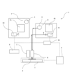
- FIG. 2 is a schematic diagram showing one embodiment of the combined Raman-infrared spectroscopic analysis apparatus of the present invention, showing a state in which it has been switched to a Raman photodetection system.
- 1 is a schematic diagram showing one embodiment of the combined Raman-infrared spectroscopic analysis apparatus of the present invention, showing a state in which it has been switched to an infrared light detection system.
- FIG. 4 is a schematic diagram showing another embodiment of the combined Raman-infrared spectroscopic analysis apparatus of the present invention, showing a state in which a half mirror is used to switch to a Raman photodetection system.
- FIG. 4 is a schematic diagram showing another embodiment of the combined Raman-infrared spectroscopic analysis apparatus of the present invention, showing a state in which a half mirror is used to switch to an infrared light detection system.
- Schematic diagram of when a circle is given to the stage as a marker and the marker is visually recognized in the visible image generated by the optical imaging device of the infrared light detection system.
- the combined Raman-infrared spectroscopic analysis apparatus 1 of the present invention includes a light source A for Raman spectroscopic analysis, a plate 2, a stage 3, a driving unit 4, an objective optical element 5, an objective optical element 6, a Raman light detection system 7, and an infrared light detection.
- the system 8 includes an optical imaging element 10 in the Raman light detection system 7, and an infrared spectroscopic analysis light source B and an optical imaging element 11 in the infrared light detection system 8, respectively.
- a plate 2 is arranged on the stage 3 .
- Light emitted from a light source A in FIG. 1 reaches an objective optical element 5, which is a microscope optical system, through various optical elements (not shown).
- the arrow represents the traveling direction of light.
- the light emitted from the light source A used in Raman spectroscopic analysis is, for example, visible or near-infrared laser light with a wavelength of several micrometers to several tens of micrometers.
- the light source B used in the infrared spectroscopic analysis is infrared light emitted from a ceramic heater. A combination of wavelengths is used.
- the objective optical element 5 has a configuration in which a convex lens and a concave lens are combined, and the light incident on the objective optical element 5 is focused on a sample to be measured (hereinafter also referred to as "sample") fixed to the plate 2 by these lenses. tie the The Raman light scattered by the sample is guided to the Raman light detection system 7 by various optical elements (not shown). A part of the Raman light guided to the Raman light detection system 7 is guided to an optical imaging device 10 of the Raman light detection system 7 by various optical elements (not shown). Part of the Raman light guided to the Raman light detection system 7 is guided to a Raman spectrometer 71 by various optical elements (not shown).
- the optical imaging device 10 Since the optical imaging device 10 generates a visible image of the area where the Raman light is scattered, the measurement area of the sample whose Raman light is being measured by the optical imaging device 10 can be confirmed.
- the optical imaging device 10 is, for example, a CCD (Charge Coupled Device) image sensor, a CMOS (Complementary Metal Oxide Semiconductor) image sensor, or the like, and is configured to be capable of imaging a still image or moving image of a sample.
- the optical imaging element 10 captures all or at least any of a bright-field image, a dark-field image, a phase-contrast image, a fluorescence image, a polarizing microscope image, etc. of the sample, depending on the configuration of the objective optical element 5 and transmitted illumination (not shown). or can be imaged.
- the optical imaging device 10 outputs the captured image to a control unit 12, which will be described later, or another information processing device.
- the Raman spectrometer 71 generates a one-dimensional or two-dimensional spectroscopic image of Raman scattered light from the sample, and obtains a Raman scattering spectrum (hereinafter also referred to as "Raman spectrum") from the one-dimensional or two-dimensional spectroscopic image. do.
- the Raman spectrometer 71 extracts a flat spectrum of an area in which an object to be observed does not exist from among the generated one-dimensional or two-dimensional spectroscopic images, and then obtains the difference between that spectrum and the spectrum of each pixel. It is also possible to obtain a spectrum.
- a Raman spectrum is typically a plot of emitted light intensity versus wavelength. The emitted light includes scattered light due to Raman scattering, and the wavelength transition (Raman shift) of the scattered light due to Raman scattering varies depending on the molecular structure and crystal structure of the sample.
- the Raman spectrometer 71 outputs the obtained Raman spectrum to a monitor or the like (not shown), and stores it in a memory storage unit (not shown) if necessary.
- the Raman photodetection system 7 may have the information processor, monitor, memory storage, and other necessary components.
- the light is dispersed by an infrared spectroscope (not shown) provided in the external spectrometer 81 and reaches the objective optical element 6, which is a microscope optical system.
- arrows indicate the traveling direction of light, as in FIG.
- the objective optical element 6 is preferably a Cassegrain mirror, which is a combination of a concave mirror and a convex mirror.
- a part of the infrared light guided to the infrared light detection system 8 is guided to an optical imaging device 11 of the infrared light detection system 8 by various optical elements (not shown).
- part of the infrared light guided to the infrared light detection system 8 is guided to an infrared spectrometer 81 by various optical elements (not shown) and guided to an infrared detector (not shown).
- the optical imaging element 11 Since the optical imaging element 11 generates a visible image of the area where the infrared light is reflected, the measurement area of the sample whose infrared light is being measured by the optical imaging element 11 can be confirmed.
- the optical imaging device 11 may have the same configuration as the optical imaging device 10 .
- the optical imaging device 11 captures a bright-field image, a dark-field image, a phase-contrast image, a fluorescent image, and a All or at least one of such as a polarizing microscope image can be captured.
- the optical imaging device 11 outputs the captured image to the control unit 12, which will be described later, or another information processing device.
- the infrared spectrometer 81 is preferably a Fourier transform infrared spectrometer.
- the spectrometer included in infrared spectrometer 81 preferably comprises a Michelson interferometer.
- the light reflected by the sample is guided to an infrared light detection system, partly to the optical imaging device 11 and partly to the infrared spectrometer 81 again.
- a detector (not shown) is arranged in the infrared spectrometer 81, and the light guided to the infrared spectrometer 81 is guided to the detector by an optical element (not shown). This detector detects infrared light.
- the detector is connected to Fourier transform computing means.
- This Fourier transform computing means computes an infrared spectrum by Fourier transforming the infrared light intensity detected by the detector, and furthermore, the infrared spectrum of the sample, which is the difference between the infrared spectra of the sample and the background. is calculated.
- the infrared spectrometer 81 outputs the acquired infrared spectrum to a monitor or the like (not shown), and stores it in a memory storage unit (not shown) if necessary.
- the infrared light detection system 8 may have the information processing device, monitor, memory storage, and other necessary components.
- the combined Raman-infrared spectroscopic analysis apparatus 1 of the present invention switches between the Raman spectroscopic measurement and the infrared spectroscopic measurement by the switching mechanism 9 as necessary.
- the order of switching between Raman spectroscopic measurement and infrared spectroscopic measurement may be either from Raman spectroscopic measurement to infrared spectroscopic measurement or from infrared spectroscopic measurement to Raman spectroscopic measurement.
- the number of times of switching is not particularly limited, and switching may be performed as many times as necessary.
- the driving unit 4 drives the plate 2 or the stage 3 to which the plate 2 is fixed, A positional relationship between the objective optical element 5 and the plate 2 and between the objective optical element 6 and the plate 2 is adjusted.
- the driving unit 4 may also have a function of moving the plate to change the observation position in the Raman spectroscopic measurement and the infrared spectroscopic measurement.
- the positional relationship between the objective optical element 5 and the plate 2 is adjusted so that the light collected by the objective optical element 5 is focused on a predetermined measurement area of the sample.
- the positional relationship between the objective optical element 6 and the plate 2 is adjusted so that the light collected by the objective optical element 6 is focused on a predetermined measurement area of the sample.
- the infrared light detection system 8 has an infrared detector 82 in addition to the infrared spectrometer 81 .
- the infrared spectrometer 81 incorporates a light source B for infrared spectroscopic analysis separately from a light source for Raman spectroscopic analysis, and has an infrared spectrometer (not shown).
- the infrared spectrometer included in infrared spectrometer 81 is preferably a Michelson interferometer.
- FIG. 3 shows an embodiment using half mirrors as beam splitters for the optical elements 131 and 132 .
- the light emitted from the light source A is irradiated onto the sample through the objective optical element 5 using an optical element as appropriate, and the scattered Raman light is sent by the half mirrors 132 and 131 partly to the optical imaging element 10 and partly to the Raman It is led to spectrometer 71 .
- a reflecting mirror is used for the optical element 135, and the light emitted from the light source B different from the one for Raman spectroscopic analysis incorporated in the infrared spectrometer 81 is emitted from the infrared spectrometer (not shown) of the infrared spectrometer. , and then to the objective optical element 6 .
- the light irradiated to the sample through the objective optical element 6 passes through the objective optical element 6 again and passes through the optical elements 133 and 134 using a half mirror as a beam splitter. It is guided to vessel 82 .
- a Raman spectrum and an infrared spectrum are obtained in the Raman light detection system and the infrared light detection system, respectively, as described above.
- the optical elements 131 to 135 are moved by the drive unit, and the objective optical element 5, the objective optical element 6 and the stage 3 are driven to move the objective optical element 5 or the objective optical element.
- the sample is irradiated with the light that has passed through the element 6 .
- the switching is not limited to FIGS. 3 and 4, and may be performed by driving the light source, the optical element, and the stage 3, or by other methods.
- the optical axis center of the objective optical element of the Raman light detection system or the objective optical element of the infrared light detection system with respect to the sample may shift.
- the measurement position or measurement region of the sample differs between Raman spectroscopic analysis and infrared spectroscopic analysis.
- at least one of the plate 2 and the stage 3 is provided with the position of the objective optical element 5 and the plate 2, and the position of the objective optical element 6 and the plate 2. Markers are given to adjust the relationship.
- This marker is visible in the captured image by the optical imaging device 10 and the optical imaging device 11 that produce the visible image. Therefore, by comparing the positions of the respective markers appearing in the visible images generated by the optical imaging element 10 and the optical imaging element 11, the objective optical element of the Raman light detection system and the objective of the infrared light detection system can be detected. It is possible to confirm the extent of deviation of the optical axis center of the optical element with respect to the sample.
- markers include various shapes such as lines, dots, combinations thereof, circles, rectangles, triangles, and crosses. These markers may be attached to at least one of the plate 2 and the stage 3, and are preferably attached to the stage 3 because they are not affected by the position of the plate.
- FIG. 5 is a schematic diagram when a circle is given to the stage as a marker, and the marker 22 is visually recognized in the visible image 21 generated by the optical imaging device 10.
- FIG. FIG. 6 is a schematic diagram when the marker 32 is viewed in the visible image 31 generated by the optical imaging device 11. As shown in FIG. By matching the magnifications of the visible images 21 and 31, when the optical axis of the objective optical element of the Raman light detection system or the objective optical element of the infrared light detection system deviates, the marker 22 in FIG. 5 and the marker in FIG. The position of 32 is shifted.
- the deviation between the markers 22 and 32 can be quantified by comparing the visible images 21 and 31 .
- the optical imaging device 10 and the optical imaging device 11 generate visible images
- the displacement of the markers can be quantified by comparing the positions of the markers 22 and 32 and the reference line.
- dots may be added to the centers of the markers 22 and 32, while a dot may also be added to the center of the marked line 41, and the distance between the positions of the dots may be the deviation.
- the visible image may be divided into pixels, the position of each marker may be represented by pixels, and the deviation between the two may be obtained, or the deviation from the reference line may be represented by pixels.
- the control unit 12 controls the driving unit 4 to adjust the positional relationship between the objective optical element 5 and the plate 2 and between the objective optical element 6 and the plate 2 .
- the control unit 12 has a storage unit, and stores the deviation between the reference line 41 and the markers 22 and 32 determined by the above method. Controlling the drive unit 4 by the control unit 12 so as to adjust the positional relationship between the objective optical element 5 and the plate 2, and between the objective optical element 6 and the plate 2, based on the stored information, is not a burden on the measurer. preferable.
- the present invention makes it possible to visualize a marker attached to at least one of a plate for fixing a sample and a stage for arranging the plate when irradiating a sample with light and detecting Raman scattered light and infrared light from the sample. Confirm on the image, confirm the displacement of the marker, and if the marker is displaced, adjust the positional relationship between the position of the plate and the objective optical element for Raman light detection and the objective optical element for infrared light detection. , Raman spectroscopy and infrared spectroscopy. Markers and marker offsets are as described above. Alternatively, deviation of the marker can be confirmed by the reference line and quantified in the same manner as described above. Quantification of the shift is as described above.
- the positional relationship between the objective optical element 5 and the plate 2 and between the objective optical element 6 and the plate 2 is adjusted based on the quantification of the displacement, and Raman spectroscopy and infrared spectroscopy are measured. It is preferable to adjust the positional relationship by moving the stage on which the plate is arranged.
- the Raman spectroscopy and infrared spectroscopy measurement method of the present invention can be performed using the Raman-infrared spectroscopy complex.
- the switching unit switches between an objective optical element for obtaining the Raman light and an objective optical element for obtaining the infrared light in response to switching between the Raman light detection system and the infrared light detection system.
- the combined Raman-infrared spectroscopic analysis apparatus according to [1] above.
- the combined Raman-infrared spectroscopic analysis apparatus according to either [1] or [2], wherein the visible image of the Raman light detection system and the visible image of the infrared light detection system each have a reference line.
- the control unit has a storage unit, and when switching between the Raman light detection system and the infrared light detection system, the storage unit displays the visible image of the Raman light detection system and the image of the infrared light detection system.
- the controller controls the position of the plate and the objective optical element for obtaining the Raman light or the objective optical element for obtaining the infrared light based on the amount of deviation stored in the storage unit.
- the combined Raman-infrared spectroscopic analysis apparatus according to [4], wherein the shift amount is a pixel shift amount on the visible image.
- the drive unit drives the stage to adjust the positional relationship between the position of the plate and the objective optical element for obtaining the Raman light and the objective optical element for obtaining the infrared light.
- the combined Raman-infrared spectroscopic analysis apparatus according to any one of [1] to [5].
- the present invention [10] irradiating the sample with light, When detecting Raman and infrared light from a sample, confirming a marker attached to at least one of a plate for fixing a sample and a stage for arranging the plate on a visible image; Checking the deviation of the marker, If the marker is misaligned, adjusting the positional relationship between the position of the plate and the objective optical element for Raman light detection and the objective optical element for infrared light detection, Measurement method by Raman spectroscopy and infrared spectroscopy.
- an analysis method using Raman spectroscopy and infrared spectroscopy that quickly matches the analysis regions of Raman spectroscopy and infrared spectroscopy by adjusting the optical axis center of the sample in the microscope optical system. is provided.
- the optical axis center of the microscope optical system for the sample can be adjusted more quickly, and the analysis regions of Raman spectroscopic analysis and infrared spectroscopic analysis can be easily matched.
- a method of analysis by external spectroscopy is provided.
- Infrared/Raman compound machine 2 Plate 3: Stage 4: Driving unit 5: Objective optical element 6: Objective optical element 7: Raman light detection system 71: Raman spectrometer 8: Infrared light detection system 81: Infrared Spectrometer 82: Infrared detector 9: Switching mechanism 10, 11: Optical imaging element 12: Control unit 131 to 135: Optical element 21, 22: Visible image 31, 32: Marker 41: Reference line A: Raman spectroscopic analysis light source B: Light source for infrared spectroscopic analysis
Landscapes
- Physics & Mathematics (AREA)
- General Physics & Mathematics (AREA)
- Chemical & Material Sciences (AREA)
- Analytical Chemistry (AREA)
- Health & Medical Sciences (AREA)
- Biochemistry (AREA)
- Engineering & Computer Science (AREA)
- Pathology (AREA)
- Immunology (AREA)
- Spectroscopy & Molecular Physics (AREA)
- General Health & Medical Sciences (AREA)
- Life Sciences & Earth Sciences (AREA)
- Optics & Photonics (AREA)
- Multimedia (AREA)
- Theoretical Computer Science (AREA)
- Mathematical Physics (AREA)
- Nuclear Medicine, Radiotherapy & Molecular Imaging (AREA)
- Investigating, Analyzing Materials By Fluorescence Or Luminescence (AREA)
- Microscoopes, Condenser (AREA)
Abstract
Description
特許文献2には顕微鏡光学系と紫外、可視または赤外領域の吸収スペクトルとラマンスペクトルを取得する分光部を備えた観測装置が記載されている。 Recently, an analysis method combined with a microscope for analysis of minute samples or analysis of minute regions is also known.
赤外光検出系の対物光学素子またはラマン光検出系の対物光学素子のサンプルに対する光軸中心がずれると、ラマン光の測定位置と赤外光の測定位置にずれが生じる。このずれは微小試料または微小測定領域ではより顕著となる。 However, when the microscope optical system is switched, the optical axis center of the objective optical element of the infrared light detection system or the objective optical element of the Raman light detection system with respect to the sample is shifted due to the optical configuration.
If the optical axis center of the objective optical element of the infrared light detection system or the objective optical element of the Raman light detection system with respect to the sample shifts, the Raman light measurement position and the infrared light measurement position shift. This deviation becomes more pronounced in a minute sample or minute measurement area.
さらに本発明は顕微鏡光学系のサンプルに対する光軸中心を調整することで、迅速にラマン分光分析および赤外分光分析の分析領域を一致させるラマン分光および赤外分光による分析方法の提供を目的とする。 The present invention does not impose an excessive burden on the operator, and even if the Raman light detection system and the infrared light detection system are continuously switched, the optical axis center of the microscope optical system for the sample can be adjusted, and Raman spectroscopic analysis and analysis can be performed quickly. It is an object of the present invention to provide a combined Raman-infrared spectroscopic analysis apparatus with the same analysis area for infrared spectroscopic analysis.
A further object of the present invention is to provide an analysis method using Raman spectroscopy and infrared spectroscopy that quickly matches the analysis regions of Raman spectroscopy and infrared spectroscopy by adjusting the center of the optical axis of the sample in the microscope optical system. .
赤外分光分析用光源とラマン分光分析用光源、
サンプルを固定するプレート、
前記プレートを配置するステージ、
前記ラマン分光分析用光源からの光をサンプルに入射させラマン光を得るための対物光学素子、
前記赤外分光分析用光源からの光をサンプルに入射させ反射した赤外光を得るための対物光学素子、
可視画像を生成するための光学撮影素子を有するラマン光検出系、および
可視画像を生成するための光学撮影素子を有する赤外光検出系、を有し、
前記プレートの位置と前記ラマン光を得るための対物光学素子および前記赤外光を得るための対物光学素子との位置関係を調整するための駆動部、
前記ラマン光検出系と前記赤外光検出系を切り替える切換え部、および
前記駆動部、前記切換え部および前記光学撮影素子を制御するための制御部、を備え、
前記プレートおよび前記ステージの少なくとも一方に前記位置関係を調整するためのマーカが付与されており、
前記制御部は、前記ラマン光検出系および前記赤外光検出系で取得された可視画像上の前記マーカの位置に基づき、前記プレートの位置と前記ラマン光を得るための対物光学素子および前記赤外光を得るための対物光学素子との位置関係を調整するように駆動部を制御するラマン-赤外分光分析複合機、
を提供する。 That is, the present invention
light source for infrared spectroscopy and light source for Raman spectroscopy,
a plate for fixing the sample,
a stage for placing the plate;
an objective optical element for obtaining Raman light by making the light from the light source for Raman spectroscopic analysis incident on the sample;
an objective optical element for obtaining infrared light reflected by incident light from the light source for infrared spectroscopic analysis on a sample;
a Raman light detection system having an optical imaging device for producing a visible image; and an infrared light detection system having an optical imaging device for producing a visible image;
a driving unit for adjusting the positional relationship between the position of the plate and the objective optical element for obtaining the Raman light and the objective optical element for obtaining the infrared light;
a switching unit for switching between the Raman light detection system and the infrared light detection system; and a control unit for controlling the driving unit, the switching unit, and the optical imaging device,
At least one of the plate and the stage is provided with a marker for adjusting the positional relationship,
Based on the positions of the markers on the visible image obtained by the Raman light detection system and the infrared light detection system, the control unit controls the position of the plate, the objective optical element for obtaining the Raman light, and the red light detection system. Raman-infrared spectroscopic analysis complex machine that controls the driving unit so as to adjust the positional relationship with the objective optical element for obtaining external light,
I will provide a.
サンプルに光を照射し、
サンプルからのラマン光および赤外光を検出する際に、
サンプルを固定するプレートおよび前記プレートを配置するステージの少なくとも一方に付与されたマーカを可視画像上で確認し、
前記マーカのずれを確認し、
マーカがずれていたら前記プレートの位置と、ラマン光検出用のラマン光を得るための対物光学素子および赤外光検出用の赤外光を得るための対物光学素子との位置関係を調整する、
ラマン分光と赤外分光による測定方法、
を提供する。 Further, the present invention
illuminate the sample and
When detecting Raman and infrared light from a sample,
confirming a marker attached to at least one of a plate for fixing a sample and a stage for arranging the plate on a visible image;
Checking the deviation of the marker,
If the marker is misaligned, the position of the plate and the positional relationship between the objective optical element for obtaining Raman light for Raman light detection and the objective optical element for obtaining infrared light for infrared light detection are adjusted.
measurement method by Raman spectroscopy and infrared spectroscopy,
I will provide a.
また本発明によれば、顕微鏡光学系のサンプルに対する光軸中心を調整することで、迅速にラマン分光分析および赤外分光分析の分析領域を一致させるラマン分光および赤外分光による分析方法が提供される。
前記本発明の結果、測定者がサンプルの移動や位置調整などを別途行う必要がなく、シームレスでラマン光および赤外光の測定が可能となる。 According to the present invention, even if the Raman light detection system and the infrared light detection system are continuously switched, the analysis area of Raman spectroscopic analysis and infrared spectroscopic analysis can be quickly adjusted by adjusting the optical axis center of the microscope optical system with respect to the sample. A matching Raman-infrared spectroscopy complex is provided.
Further, according to the present invention, there is provided a method of analysis by Raman spectroscopy and infrared spectroscopy that quickly matches the analysis regions of Raman spectroscopy and infrared spectroscopy by adjusting the center of the optical axis of the sample in the microscope optical system. be.
As a result of the present invention, it is possible to seamlessly measure Raman light and infrared light without the need for an operator to separately move or adjust the position of the sample.
ラマン分光分析で用いられる光源Aから出射される光は、例えば可視もしくは近赤外域のレーザー光であり波長は数μmから数十μmの光である。
また赤外分光分析で用いられる光源Bは、セラミックヒーターから出射される赤外光であり、例えば短い波長例として405nmから長い波長例である1064nmまでの波長が使用され、多くは532nmと785nmの組み合わせの波長が用いられる。 Light emitted from a light source A in FIG. 1 reaches an objective
The light emitted from the light source A used in Raman spectroscopic analysis is, for example, visible or near-infrared laser light with a wavelength of several micrometers to several tens of micrometers.
The light source B used in the infrared spectroscopic analysis is infrared light emitted from a ceramic heater. A combination of wavelengths is used.
ラマン光検出系7に導かれたラマン光の一部は各種光学素子(図示せず)によりラマン光検出系7が有する光学撮影素子10へ導かれる。またラマン光検出系7に導かれたラマン光の一部は各種光学素子(図示せず)によりラマン分光計71に導かれる。 The objective
A part of the Raman light guided to the Raman
光学撮影素子10は例えば、CCD(Charge Coupled Device)イメージセンサやCMOS(Complementary Metal Oxide Semiconductor)イメージセンサ等が挙げられ、サンプルの静止画あるいは動画を撮像可能に構成されている。光学撮影素子10は、対物光学素子5や透過照明(図示せず)の構成に応じて、サンプルの明視野像、暗視野像、位相差像、蛍光像、偏光顕微鏡像等の全部または少なくともいずれかを撮像することができる。光学撮影素子10は、撮像した画像を後述する制御部12あるいは他の情報処理装置等に出力する。 Since the
The
ラマン分光計71は、生成した1次元または2次元分光画像のうち、観測対象物の存在しない領域のフラットなスペクトルを抽出した後、そのスペクトルと各画素のスペクトルの差を取ることでサンプルのラマンスペクトルを得ることも可能である。ラマンスペクトルは、通常、放出光の強度を波長に対してプロットしたものである。放出光は、ラマン散乱による散乱光を含んでおり、ラマン散乱による散乱光の波長遷移(ラマンシフト)は、サンプルの分子構造や結晶構造によって異なる。 The
The
ラマン光検出系7は前記光学撮影素子10、前記ラマン分光計71に加えて、前記情報処理装置、モニター、メモリー格納部、およびその他の必要な部品を有していてもよい。 The
In addition to the
赤外光検出系8に導かれた赤外光の一部は各種光学素子(図示せず)により赤外光検出系8が有する光学撮影素子11へ導かれる。また赤外光検出系8に導かれた赤外光の一部は各種光学素子(図示せず)により赤外分光計81に導かれ、赤外検出器(図示せず)に導かれる。 Light incident on the
A part of the infrared light guided to the infrared
光学撮影素子11は前記光学撮影素子10と同じ構成が例示できる。光学撮影素子11は、対物光学素子5や試料の性質によって使い分けられる透過または反射による照明(図示せず)の構成に応じて、サンプルの明視野像、暗視野像、位相差像、蛍光像、偏光顕微鏡像等の全部または少なくともいずれかを撮像することができる。光学撮影素子11は、撮像した画像を後述する制御部12あるいは他の情報処理装置等に出力する。 Since the
The
赤外光検出系8は前記光学撮影素子11、赤外分光計81に加えて、前記情報処理装置、モニター、メモリー格納部、およびその他の必要な部品を有していてもよい。 The
In addition to the
ラマン分光測定に切換えた場合は、対物光学素子5により集光された光がサンプルの所定の測定領域に集光するように対物光学素子5とプレート2の位置関係を調整する。
赤外分光測定に切換えた場合は、対物光学素子6により集光された光がサンプルの所定の測定領域に集光するように対物光学素子6とプレート2の位置関係を調整する。 In response to switching from Raman spectroscopic measurement to infrared spectroscopic measurement or from infrared spectroscopic measurement to Raman spectroscopic measurement by the switching mechanism, the driving
When switching to Raman spectroscopic measurement, the positional relationship between the objective
When switching to infrared spectroscopic measurement, the positional relationship between the objective
赤外分光計81は赤外分光分析用の光源Bをラマン分光分析用の光源とは別に内蔵しており、赤外分光計(図示せず)を有している。赤外分光計81が有する赤外分光計はマイケルソン干渉計が好ましい。 3 and 4 are schematic diagrams in the case of switching between Raman spectroscopic measurement and infrared spectroscopic measurement using
The
ラマン光検出系および赤外光検出系では前記のとおりラマンスペクトルおよび赤外スペクトルがそれぞれ取得される。 In FIG. 4, a reflecting mirror is used for the
A Raman spectrum and an infrared spectrum are obtained in the Raman light detection system and the infrared light detection system, respectively, as described above.
切換えは図3および図4に限定されるものではなく、例えば光源、光学素子およびステージ3を駆動させてもよく、他の手法で切換えてもよい。 3 and 4, the
The switching is not limited to FIGS. 3 and 4, and may be performed by driving the light source, the optical element, and the
このずれを修正するため、本発明のラマン-赤外分光分析複合装置では前記プレート2または前記ステージ3の少なくとも一方に、前記対物光学素子5とプレート2、および対物光学素子6とプレート2の位置関係を調整するためのマーカが付与されている。
このマーカは可視画像を生成する前記光学撮影素子10および前記光学撮影素子11により撮影画像にて視認される。したがって、前記光学撮影素子10および前記光学撮影素子11により生成した可視画像に写るぞれぞれのマーカの位置を比較することで、ラマン光検出系の対物光学素子と赤外光検出系の対物光学素子のサンプルに対する光軸中心のずれの程度を確認することができる。 As described above, when switching between the Raman light detection system and the infrared light detection system, the optical axis center of the objective optical element of the Raman light detection system or the objective optical element of the infrared light detection system with respect to the sample may shift. In some cases, the measurement position or measurement region of the sample differs between Raman spectroscopic analysis and infrared spectroscopic analysis.
In order to correct this deviation, in the combined Raman-infrared spectroscopic analysis apparatus of the present invention, at least one of the
This marker is visible in the captured image by the
マーカは例えば線、点、これらの組み合わせ、円形、矩形、三角形、十字形などの各種形状が挙げられる。これらマーカは前記プレート2または前記ステージ3の少なくとも一方に付与されていればよく、ステージ3に付与されているのがプレートの位置の影響を受けないので好ましい。 The positional relationships between the objective
Examples of markers include various shapes such as lines, dots, combinations thereof, circles, rectangles, triangles, and crosses. These markers may be attached to at least one of the
定量の方法は例えば可視画像をピクセルで分割し、各マーカの位置をピクセルで表して両者のずれを求めてもよいし、前記標線とのずれをピクセルで表してもよい。 The deviation between the
As a method of quantification, for example, the visible image may be divided into pixels, the position of each marker may be represented by pixels, and the deviation between the two may be obtained, or the deviation from the reference line may be represented by pixels.
制御部12は記憶部を有し、前記方法により定量された前記標線41と前記マーカ22およびマーカ32とのずれを記憶し、ラマン光検出系と赤外光検出系を切換える毎に、前記記憶に基づき、前記対物光学素子5とプレート2、および対物光学素子6とプレート2の位置関係をそれぞれ調整するように制御部12により駆動部4を制御するのが、測定者の負担の観点から好ましい。 Based on the quantified deviation, the
The
マーカおよびマーカのずれは前記のとおりである。またはマーカのずれは前記標線にて確認し、前記と同様にして定量できる。
ずれの定量は前記のとおりである。
前記ずれの定量に基づき前記対物光学素子5とプレート2、および対物光学素子6とプレート2の位置関係をそれぞれ調整し、ラマン分光と赤外分光を測定する。位置関係の調整はプレートが配置されたステージを動かして行うのが好ましい。 In addition, the present invention makes it possible to visualize a marker attached to at least one of a plate for fixing a sample and a stage for arranging the plate when irradiating a sample with light and detecting Raman scattered light and infrared light from the sample. Confirm on the image, confirm the displacement of the marker, and if the marker is displaced, adjust the positional relationship between the position of the plate and the objective optical element for Raman light detection and the objective optical element for infrared light detection. , Raman spectroscopy and infrared spectroscopy.
Markers and marker offsets are as described above. Alternatively, deviation of the marker can be confirmed by the reference line and quantified in the same manner as described above.
Quantification of the shift is as described above.
The positional relationship between the objective
上述した例示的な実施形態は、以下の態様の具体例であることが当業者により理解される。 [Aspect]
It will be appreciated by those skilled in the art that the exemplary embodiments described above are specific examples of the following aspects.
サンプルを固定するプレート、
前記プレートを配置するステージ、
前記ラマン分光分析用光源からの光をサンプルに入射させラマン光を得るための対物光学素子、
前記赤外分光分析用光源からの光をサンプルに入射させ反射した赤外光を得るための対物光学素子、
可視画像を生成するための光学撮影素子を有するラマン光検出系、および
可視画像を生成するための光学撮影素子を有する赤外光検出系、を有し、
前記プレートの位置と前記ラマン光を得るための対物光学素子および前記赤外光を得るための対物光学素子との位置関係を調整するための駆動部、
前記ラマン光検出系と前記赤外光検出系を切り替える切換え部、および
前記駆動部、前記切換え部および前記光学撮影素子を制御するための制御部、を備え、
前記プレートおよび前記ステージの少なくとも一方に前記位置関係を調整するためのマーカが付与されており、
前記制御部は、前記ラマン光検出系および前記赤外光検出系で取得された可視画像上の前記マーカの位置に基づき、前記プレートの位置と前記ラマン光を得るための対物光学素子および前記赤外光を得るための対物光学素子との位置関係を調整するように駆動部を制御するラマン-赤外分光分析複合機。 [1] A light source for infrared spectroscopic analysis and a light source for Raman spectroscopic analysis,
a plate for fixing the sample,
a stage for placing the plate;
an objective optical element for obtaining Raman light by making the light from the light source for Raman spectroscopic analysis incident on the sample;
an objective optical element for obtaining infrared light reflected by incident light from the light source for infrared spectroscopic analysis on a sample;
a Raman light detection system having an optical imaging device for producing a visible image; and an infrared light detection system having an optical imaging device for producing a visible image;
a driving unit for adjusting the positional relationship between the position of the plate and the objective optical element for obtaining the Raman light and the objective optical element for obtaining the infrared light;
a switching unit for switching between the Raman light detection system and the infrared light detection system; and a control unit for controlling the driving unit, the switching unit, and the optical imaging device,
At least one of the plate and the stage is provided with a marker for adjusting the positional relationship,
Based on the positions of the markers on the visible image obtained by the Raman light detection system and the infrared light detection system, the control unit controls the position of the plate, the objective optical element for obtaining the Raman light, and the red light detection system. A combined Raman-infrared spectroscopic analysis machine that controls a drive unit so as to adjust the positional relationship with an objective optical element for obtaining external light.
[4]前記制御部が記憶部を有し、前記記憶部は前記ラマン光検出系と前記赤外光検出系の切換え時に、前記ラマン光検出系の可視画像上および前記赤外光検出系の可視画像上の前記マーカ位置と、前記ラマン光検出系の可視画像および前記赤外光検出系の可視画像の標線とのずれ量を記憶し、前記ラマン光検出系と前記赤外光検出系の切換え毎に、前記記憶部に記憶された前記ずれ量に基づき、前記制御部が前記プレートの位置と前記ラマン光を得るための対物光学素子または前記赤外光を得るための対物光学素子との位置関係を調整する請求項3に記載のラマン-赤外分光分析複合機。 [3] The combined Raman-infrared spectroscopic analysis apparatus according to either [1] or [2], wherein the visible image of the Raman light detection system and the visible image of the infrared light detection system each have a reference line.
[4] The control unit has a storage unit, and when switching between the Raman light detection system and the infrared light detection system, the storage unit displays the visible image of the Raman light detection system and the image of the infrared light detection system. storing the amount of deviation between the marker position on the visible image, the visible image of the Raman light detection system, and the reference line of the visible image of the infrared light detection system, and storing the Raman light detection system and the infrared light detection system; every time switching is performed, the controller controls the position of the plate and the objective optical element for obtaining the Raman light or the objective optical element for obtaining the infrared light based on the amount of deviation stored in the storage unit. The Raman-infrared spectroscopic analysis complex machine according to
[6]前記駆動部が、前記プレートの位置と前記ラマン光を得るための対物光学素子および前記赤外光を得るための対物光学素子との位置関係を調整するために前記ステージを駆動する前記[1]から[5]のいずれか一項に記載のラマン-赤外分光分析複合機。
[7]前記マーカが前記ステージ上に付与されている前記[1]から[6]のいずれかに記載のラマン-赤外分光分析複合機。
[8]前記赤外光を得るための対物光学素子がカセグレン鏡である前記[1]から[7]のいずれかに記載のラマン-赤外分光分析複合機。
[9]ラマン光源が532nmと785nmの光を照射する前記[1]から[8]に記載のいずれかに記載のラマン-赤外分光分析複合機。 [5] The combined Raman-infrared spectroscopic analysis apparatus according to [4], wherein the shift amount is a pixel shift amount on the visible image.
[6] The drive unit drives the stage to adjust the positional relationship between the position of the plate and the objective optical element for obtaining the Raman light and the objective optical element for obtaining the infrared light. The combined Raman-infrared spectroscopic analysis apparatus according to any one of [1] to [5].
[7] The combined Raman-infrared spectroscopic analysis apparatus according to any one of [1] to [6], wherein the marker is provided on the stage.
[8] The combined Raman-infrared spectroscopic analysis apparatus according to any one of [1] to [7], wherein the objective optical element for obtaining the infrared light is a Cassegrain mirror.
[9] The combined Raman-infrared spectroscopic analysis apparatus according to any one of [1] to [8], wherein the Raman light source emits light of 532 nm and 785 nm.
[10]サンプルに光を照射し、
サンプルからのラマン光および赤外光を検出する際に、
サンプルを固定するプレートおよび前記プレートを配置するステージの少なくとも一方に付与されたマーカを可視画像上で確認し、
前記マーカのずれを確認し、
マーカがずれていたら前記プレートの位置と、ラマン光検出用の対物光学素子および赤外光検出用の対物光学素子との位置関係を調整する、
ラマン分光と赤外分光による測定方法。 Further, the present invention
[10] irradiating the sample with light,
When detecting Raman and infrared light from a sample,
confirming a marker attached to at least one of a plate for fixing a sample and a stage for arranging the plate on a visible image;
Checking the deviation of the marker,
If the marker is misaligned, adjusting the positional relationship between the position of the plate and the objective optical element for Raman light detection and the objective optical element for infrared light detection,
Measurement method by Raman spectroscopy and infrared spectroscopy.
[12]ラマン光検出用のラマン光を得るための対物光学素子および赤外光検出用の赤外光を得るための対物光学素子との位置関係を調整をステージを動かして行う前記[10]または[11]のいずれかに記載の測定方法。 [11] The measuring method according to [10] above, wherein the displacement of the marker is confirmed by the displacement between the marker and a marked line provided on the visible image.
[12] Moving the stage to adjust the positional relationship between the objective optical element for obtaining Raman light for Raman light detection and the objective optical element for obtaining infrared light for infrared light detection [10] Or the measurement method according to any one of [11].
2:プレート
3:ステージ
4:駆動部
5:対物光学素子
6:対物光学素子
7:ラマン光検出系
71:ラマン分光計
8:赤外光検出系
81:赤外分光計
82:赤外検出器
9:切替え機構
10、11:光学撮影素子
12:制御部
131から135:光学素子
21、22:可視画像
31、32:マーカ
41:標線
A:ラマン分光分析光源
B:赤外分光分析用光源
1: Infrared/Raman compound machine 2: Plate 3: Stage 4: Driving unit 5: Objective optical element 6: Objective optical element 7: Raman light detection system 71: Raman spectrometer 8: Infrared light detection system 81: Infrared Spectrometer 82: Infrared detector 9:
Claims (12)
- 赤外分光分析用光源とラマン分光分析用光源、
サンプルを固定するプレート、
前記プレートを配置するステージ、
前記ラマン分光分析用光源からの光をサンプルに入射させラマン光を得るための対物光学素子、
前記赤外分光分析用光源からの光をサンプルに入射させ反射した赤外光を得るための対物光学素子、
可視画像を生成するための光学撮影素子を有するラマン光検出系、および
可視画像を生成するための光学撮影素子を有する赤外光検出系、を有し、
前記プレートの位置と前記ラマン光を得るための対物光学素子および前記赤外光を得るための対物光学素子との位置関係を調整するための駆動部、
前記ラマン光検出系と前記赤外光検出系を切り替える切換え部、および
前記駆動部、前記切換え部および前記光学撮影素子を制御するための制御部、を備え、
前記プレートおよび前記ステージの少なくとも一方に前記位置関係を調整するためのマーカが付与されており、
前記制御部は、前記ラマン光検出系および前記赤外光検出系で取得された可視画像上の前記マーカの位置に基づき、前記プレートの位置と前記ラマン光を得るための対物光学素子および前記赤外光を得るための対物光学素子との位置関係を調整するように駆動部を制御するラマン-赤外分光分析複合機。 light source for infrared spectroscopy and light source for Raman spectroscopy,
a plate for fixing the sample,
a stage for placing the plate;
an objective optical element for obtaining Raman light by making the light from the light source for Raman spectroscopic analysis incident on the sample;
an objective optical element for obtaining infrared light reflected by incident light from the light source for infrared spectroscopic analysis on a sample;
a Raman light detection system having an optical imaging device for producing a visible image; and an infrared light detection system having an optical imaging device for producing a visible image;
a driving unit for adjusting the positional relationship between the position of the plate and the objective optical element for obtaining the Raman light and the objective optical element for obtaining the infrared light;
a switching unit for switching between the Raman light detection system and the infrared light detection system; and a control unit for controlling the driving unit, the switching unit, and the optical imaging device,
At least one of the plate and the stage is provided with a marker for adjusting the positional relationship,
Based on the positions of the markers on the visible image obtained by the Raman light detection system and the infrared light detection system, the control unit controls the position of the plate, the objective optical element for obtaining the Raman light, and the red light detection system. A combined Raman-infrared spectroscopic analysis machine that controls a drive unit so as to adjust the positional relationship with an objective optical element for obtaining external light. - 前記切換え部は、前記ラマン光検出系と前記赤外光検出系の切換えに対応して前記ラマン光を得るための対物光学素子と前記赤外光を得るための対物光学素子を切換える請求項1に記載のラマン-赤外分光分析複合機。 2. The switching unit switches between an objective optical element for obtaining the Raman light and an objective optical element for obtaining the infrared light corresponding to switching between the Raman light detection system and the infrared light detection system. Raman-infrared spectroscopy complex as described in .
- 前記ラマン光検出系の可視画像および前記赤外光検出系の可視画像がそれぞれ標線を有する請求項1または2のいずれかに記載のラマン-赤外分光分析複合機。 The combined Raman-infrared spectroscopic analysis apparatus according to claim 1 or 2, wherein the visible image of the Raman light detection system and the visible image of the infrared light detection system each have a reference line.
- 前記制御部が記憶部を有し、前記記憶部は前記ラマン光検出系と前記赤外光検出系の切換え時に、前記ラマン光検出系の可視画像上および前記赤外光検出系の可視画像上の前記マーカ位置と、前記ラマン光検出系の可視画像および前記赤外光検出系の可視画像の標線とのずれ量を記憶し、前記ラマン光検出系と前記赤外光検出系の切換え毎に、前記記憶部に記憶された前記ずれ量に基づき、前記制御部が前記プレートの位置と前記ラマン光を得るための対物光学素子または前記赤外光を得るための対物光学素子との位置関係を調整する請求項3に記載のラマン-赤外分光分析複合機。 The control unit has a storage unit, and the storage unit stores the visible image of the Raman light detection system and the visible image of the infrared light detection system when switching between the Raman light detection system and the infrared light detection system. and the amount of deviation between the marker position and the reference line of the visible image of the Raman light detection system and the visible image of the infrared light detection system, and each time the Raman light detection system and the infrared light detection system are switched (2) based on the amount of deviation stored in the storage unit, the control unit determines the positional relationship between the position of the plate and the objective optical element for obtaining the Raman light or the objective optical element for obtaining the infrared light; Raman-infrared spectroscopy combination machine according to claim 3, which adjusts
- 前記ずれ量が前記可視画像上のピクセルのずれ量である請求項4に記載のラマン-赤外分光分析複合機。 The combined Raman-infrared spectroscopic analysis machine according to claim 4, wherein the displacement amount is the displacement amount of pixels on the visible image.
- 前記駆動部が、前記プレートの位置と前記ラマン光を得るための対物光学素子および前記赤外光を得るための対物光学素子との位置関係を調整するために前記ステージを駆動する請求項1から5のいずれか一項に記載のラマン-赤外分光分析複合機。 2. from claim 1, wherein the drive unit drives the stage to adjust the positional relationship between the position of the plate and an objective optical element for obtaining the Raman light and an objective optical element for obtaining the infrared light. 6. The combined Raman-infrared spectroscopy analyzer according to any one of 5.
- 前記マーカが前記ステージ上に付与されている請求項1から6のいずれか一項に記載のラマン-赤外分光分析複合機。 The Raman-infrared spectroscopic analysis complex machine according to any one of claims 1 to 6, wherein the marker is provided on the stage.
- 前記赤外光を得るための対物光学素子がカセグレン鏡である請求項1から7のいずれか一項に記載のラマン-赤外分光分析複合機。 The combined Raman-infrared spectroscopic analysis apparatus according to any one of claims 1 to 7, wherein the objective optical element for obtaining the infrared light is a Cassegrain mirror.
- ラマン光源が532nmと785nmの光を照射する請求項1から8に記載のいずれか一項に記載のラマン-赤外分光分析複合機。 The Raman-infrared spectroscopic analysis complex machine according to any one of claims 1 to 8, wherein the Raman light source emits light of 532 nm and 785 nm.
- サンプルに光を照射し、
サンプルからのラマン光および赤外光を検出する際に、
サンプルを固定するプレートおよび前記プレートを配置するステージの少なくとも一方に付与されたマーカを可視画像上で確認し、
前記マーカのずれを確認し、
マーカがずれていたら前記プレートの位置と、ラマン光検出用の対物光学素子および赤外光検出用の対物光学素子との位置関係を調整する、
ラマン分光と赤外分光による測定方法。 illuminate the sample and
When detecting Raman and infrared light from a sample,
confirming a marker attached to at least one of a plate for fixing a sample and a stage for arranging the plate on a visible image;
Checking the deviation of the marker,
If the marker is misaligned, adjusting the positional relationship between the position of the plate and the objective optical element for Raman light detection and the objective optical element for infrared light detection,
Measurement method by Raman spectroscopy and infrared spectroscopy. - 前記マーカのずれを、前記マーカと可視画像上に設けられた標線とのずれで確認する請求項10に記載の測定方法。 The measuring method according to claim 10, wherein the deviation of the marker is confirmed by the deviation between the marker and a marked line provided on the visible image.
- ラマン光検出用の対物光学素子および赤外光検出用の対物光学素子との位置関係を調整をステージを動かして行う請求項10または11のいずれかに記載の測定方法。 The measuring method according to any one of claims 10 and 11, wherein the positional relationship between the objective optical element for Raman light detection and the objective optical element for infrared light detection is adjusted by moving the stage.
Priority Applications (3)
| Application Number | Priority Date | Filing Date | Title |
|---|---|---|---|
| EP22863942.3A EP4397962A1 (en) | 2021-08-31 | 2022-04-27 | Raman-infrared spectroscopic analysis multifunction machine, and measuring method employing raman spectroscopy and infrared spectroscopy |
| CN202280058612.9A CN117897609A (en) | 2021-08-31 | 2022-04-27 | Raman infrared spectrum analysis compound machine and measuring method using Raman light and infrared light |
| JP2023545079A JPWO2023032352A1 (en) | 2021-08-31 | 2022-04-27 |
Applications Claiming Priority (2)
| Application Number | Priority Date | Filing Date | Title |
|---|---|---|---|
| JP2021140776 | 2021-08-31 | ||
| JP2021-140776 | 2021-08-31 |
Publications (1)
| Publication Number | Publication Date |
|---|---|
| WO2023032352A1 true WO2023032352A1 (en) | 2023-03-09 |
Family
ID=85411146
Family Applications (1)
| Application Number | Title | Priority Date | Filing Date |
|---|---|---|---|
| PCT/JP2022/019042 WO2023032352A1 (en) | 2021-08-31 | 2022-04-27 | Raman-infrared spectroscopic analysis multifunction machine, and measuring method employing raman spectroscopy and infrared spectroscopy |
Country Status (4)
| Country | Link |
|---|---|
| EP (1) | EP4397962A1 (en) |
| JP (1) | JPWO2023032352A1 (en) |
| CN (1) | CN117897609A (en) |
| WO (1) | WO2023032352A1 (en) |
Citations (9)
| Publication number | Priority date | Publication date | Assignee | Title |
|---|---|---|---|---|
| JP2001013095A (en) | 1999-06-30 | 2001-01-19 | Horiba Ltd | Inorganic matter analyzing apparatus in sample and inorganic and/or organic matter analyzing apparatus in sample |
| JP2008281513A (en) * | 2007-05-14 | 2008-11-20 | St Japan Inc | Cultural property inspection apparatus |
| JP2012123039A (en) * | 2010-12-06 | 2012-06-28 | Sony Corp | Microscope, region determining method, and program |
| WO2013132734A1 (en) | 2012-03-07 | 2013-09-12 | ソニー株式会社 | Observation device, observation program and observation method |
| JP2014219623A (en) * | 2013-05-10 | 2014-11-20 | ソニー株式会社 | Observation system, observation program, and observation method |
| US20150192462A1 (en) * | 2012-07-06 | 2015-07-09 | Smiths Detection, Inc. | Dual spectrometer |
| CN106442401A (en) * | 2016-11-01 | 2017-02-22 | 北京华泰诺安技术有限公司 | Detection device and method combining Raman spectroscopy with near-infrared spectroscopy |
| WO2019092772A1 (en) * | 2017-11-07 | 2019-05-16 | 株式会社島津製作所 | Accessory for infrared spectrophotometer |
| WO2020075548A1 (en) * | 2018-10-11 | 2020-04-16 | 株式会社島津製作所 | Microspectroscopy device, and microspectroscopy method |
-
2022
- 2022-04-27 CN CN202280058612.9A patent/CN117897609A/en active Pending
- 2022-04-27 JP JP2023545079A patent/JPWO2023032352A1/ja active Pending
- 2022-04-27 EP EP22863942.3A patent/EP4397962A1/en active Pending
- 2022-04-27 WO PCT/JP2022/019042 patent/WO2023032352A1/en active Application Filing
Patent Citations (9)
| Publication number | Priority date | Publication date | Assignee | Title |
|---|---|---|---|---|
| JP2001013095A (en) | 1999-06-30 | 2001-01-19 | Horiba Ltd | Inorganic matter analyzing apparatus in sample and inorganic and/or organic matter analyzing apparatus in sample |
| JP2008281513A (en) * | 2007-05-14 | 2008-11-20 | St Japan Inc | Cultural property inspection apparatus |
| JP2012123039A (en) * | 2010-12-06 | 2012-06-28 | Sony Corp | Microscope, region determining method, and program |
| WO2013132734A1 (en) | 2012-03-07 | 2013-09-12 | ソニー株式会社 | Observation device, observation program and observation method |
| US20150192462A1 (en) * | 2012-07-06 | 2015-07-09 | Smiths Detection, Inc. | Dual spectrometer |
| JP2014219623A (en) * | 2013-05-10 | 2014-11-20 | ソニー株式会社 | Observation system, observation program, and observation method |
| CN106442401A (en) * | 2016-11-01 | 2017-02-22 | 北京华泰诺安技术有限公司 | Detection device and method combining Raman spectroscopy with near-infrared spectroscopy |
| WO2019092772A1 (en) * | 2017-11-07 | 2019-05-16 | 株式会社島津製作所 | Accessory for infrared spectrophotometer |
| WO2020075548A1 (en) * | 2018-10-11 | 2020-04-16 | 株式会社島津製作所 | Microspectroscopy device, and microspectroscopy method |
Also Published As
| Publication number | Publication date |
|---|---|
| CN117897609A (en) | 2024-04-16 |
| JPWO2023032352A1 (en) | 2023-03-09 |
| EP4397962A1 (en) | 2024-07-10 |
Similar Documents
| Publication | Publication Date | Title |
|---|---|---|
| JP5092104B2 (en) | Spectrometer and spectroscopic method | |
| US9891418B2 (en) | Apparatus for imaging a sample surface | |
| US9804029B2 (en) | Microspectroscopy device | |
| EP2463616A1 (en) | Interference microscope and measuring apparatus | |
| EP1784680B1 (en) | Alignment system for spectroscopic analysis | |
| KR102341678B1 (en) | Optical characteristic measuring apparatus and optical characteristic measuring method | |
| US10067058B1 (en) | Auto-focus system | |
| CN112930470A (en) | Image guided micro-raman spectroscopy | |
| US20200249454A1 (en) | Optical microscope and spectroscopic measurement method | |
| WO2021261035A1 (en) | Raman microspectroscopic measurement device, and method for calibrating raman microspectroscopic measurement device | |
| JP2001021810A (en) | Interference microscope | |
| WO2023032352A1 (en) | Raman-infrared spectroscopic analysis multifunction machine, and measuring method employing raman spectroscopy and infrared spectroscopy | |
| KR20140103000A (en) | Fast and quantitative raman analysis method and apparatus thereof for large-area multiple bio-targets | |
| JP7318868B2 (en) | Sample measuring device, measuring method and program | |
| JP4136891B2 (en) | Fluorescence measurement device for measuring fluorescence image / spectrum | |
| JP3667397B2 (en) | Raman spectrometer | |
| JP2017151373A (en) | Infrared microscope and infrared microscope system | |
| EP2333501B1 (en) | Apparatus and method for automatic optical realignment | |
| JP2004354346A (en) | Measuring device | |
| JP2006162462A (en) | Image measuring instrument | |
| JP4713391B2 (en) | Infrared microscope | |
| JPWO2023032352A5 (en) | ||
| JP2012141452A (en) | Automatic focus mechanism and microscope device | |
| JP2002357550A (en) | Probe and raman spectrometric device using the same | |
| JP2023090228A (en) | Raman microscope |
Legal Events
| Date | Code | Title | Description |
|---|---|---|---|
| 121 | Ep: the epo has been informed by wipo that ep was designated in this application |
Ref document number: 22863942 Country of ref document: EP Kind code of ref document: A1 |
|
| WWE | Wipo information: entry into national phase |
Ref document number: 2023545079 Country of ref document: JP |
|
| WWE | Wipo information: entry into national phase |
Ref document number: 202280058612.9 Country of ref document: CN |
|
| WWE | Wipo information: entry into national phase |
Ref document number: 2022863942 Country of ref document: EP |
|
| NENP | Non-entry into the national phase |
Ref country code: DE |
|
| ENP | Entry into the national phase |
Ref document number: 2022863942 Country of ref document: EP Effective date: 20240402 |