WO2023032092A1 - Vehicle control method and vehicle control device - Google Patents
Vehicle control method and vehicle control device Download PDFInfo
- Publication number
- WO2023032092A1 WO2023032092A1 PCT/JP2021/032161 JP2021032161W WO2023032092A1 WO 2023032092 A1 WO2023032092 A1 WO 2023032092A1 JP 2021032161 W JP2021032161 W JP 2021032161W WO 2023032092 A1 WO2023032092 A1 WO 2023032092A1
- Authority
- WO
- WIPO (PCT)
- Prior art keywords
- vehicle
- distance
- inter
- lane
- target
- Prior art date
Links
- 238000000034 method Methods 0.000 title claims abstract description 33
- 230000008569 process Effects 0.000 claims description 15
- 230000008859 change Effects 0.000 claims description 11
- 230000004043 responsiveness Effects 0.000 claims description 10
- 238000004904 shortening Methods 0.000 claims description 5
- 238000012545 processing Methods 0.000 abstract description 5
- 238000004364 calculation method Methods 0.000 description 31
- 238000001514 detection method Methods 0.000 description 22
- 230000001133 acceleration Effects 0.000 description 11
- 238000010586 diagram Methods 0.000 description 10
- 230000006870 function Effects 0.000 description 8
- 230000006399 behavior Effects 0.000 description 7
- 208000019901 Anxiety disease Diseases 0.000 description 6
- 230000036506 anxiety Effects 0.000 description 6
- 238000011156 evaluation Methods 0.000 description 5
- 230000009471 action Effects 0.000 description 3
- 238000013459 approach Methods 0.000 description 3
- 230000010354 integration Effects 0.000 description 3
- 230000015654 memory Effects 0.000 description 3
- 238000004422 calculation algorithm Methods 0.000 description 1
- 238000004891 communication Methods 0.000 description 1
- 238000004590 computer program Methods 0.000 description 1
- 230000003111 delayed effect Effects 0.000 description 1
- 230000000694 effects Effects 0.000 description 1
- 230000004927 fusion Effects 0.000 description 1
- 238000003384 imaging method Methods 0.000 description 1
- 230000010365 information processing Effects 0.000 description 1
- 238000005259 measurement Methods 0.000 description 1
- 238000012986 modification Methods 0.000 description 1
- 230000004048 modification Effects 0.000 description 1
- 230000003287 optical effect Effects 0.000 description 1
- 238000005457 optimization Methods 0.000 description 1
- 230000002093 peripheral effect Effects 0.000 description 1
- 230000004044 response Effects 0.000 description 1
- 239000004065 semiconductor Substances 0.000 description 1
- 238000006467 substitution reaction Methods 0.000 description 1
Images

Classifications
-
- B—PERFORMING OPERATIONS; TRANSPORTING
- B60—VEHICLES IN GENERAL
- B60W—CONJOINT CONTROL OF VEHICLE SUB-UNITS OF DIFFERENT TYPE OR DIFFERENT FUNCTION; CONTROL SYSTEMS SPECIALLY ADAPTED FOR HYBRID VEHICLES; ROAD VEHICLE DRIVE CONTROL SYSTEMS FOR PURPOSES NOT RELATED TO THE CONTROL OF A PARTICULAR SUB-UNIT
- B60W30/00—Purposes of road vehicle drive control systems not related to the control of a particular sub-unit, e.g. of systems using conjoint control of vehicle sub-units, or advanced driver assistance systems for ensuring comfort, stability and safety or drive control systems for propelling or retarding the vehicle
Definitions
- the present invention relates to a vehicle control method and a vehicle control device.
- the inter-vehicle distance control device described in Patent Document 1 below As a technique for controlling the inter-vehicle distance so that the distance to the preceding vehicle is constant, for example, the inter-vehicle distance control device described in Patent Document 1 below is described.
- This inter-vehicle distance control device extends the inter-vehicle distance from the preceding vehicle when another vehicle is detected on the side of the own vehicle at a merging point, thereby reducing the anxiety of the drivers of the own vehicle and the other vehicle. is intended.
- the space between the merging lane and the main road may be blocked by a wall or the like until just before the merging point. Therefore, when another vehicle on another lane merging with the own vehicle travels diagonally ahead of the own vehicle, it is easy to detect the other vehicle from the own vehicle. It can be difficult to detect. In this way, when the following vehicle and the own vehicle arrive at the merging point in a side-by-side state while the following vehicle cannot be detected, the own vehicle rapidly decelerates or accelerates immediately after the following vehicle is detected, and the following vehicle is detected. It becomes necessary to adjust the relative front-rear relationship with the following vehicle. The same applies to following vehicles. As a result, the occupants of the own vehicle and the following vehicle may feel uneasy.
- the present invention is to reduce the anxiety felt by the drivers of the own vehicle and the other vehicle in a merging section where the lane in which the own vehicle is traveling and the other lane in which the other vehicle is traveling are merged in front of the own vehicle.
- the purpose is to adjust the speed of
- the vehicle control method of one aspect of the present invention whether or not a first other vehicle traveling in a second lane that merges with the first lane in which the own vehicle is traveling ahead of the own vehicle is traveling diagonally in front of the own vehicle. and when it is determined that the first other vehicle is running diagonally ahead of the own vehicle, the inter-vehicle distance to the preceding vehicle running ahead of the own vehicle on the first lane is maintained.
- the vehicle speed of the own vehicle is controlled so that the front-rear distance from the rear end position of the first other vehicle to the front end position of the own vehicle in the front-rear direction of the first lane is shorter than the first target inter-vehicle distance in the vehicle speed control. process and are executed by the controller.
- the driver of the own vehicle and the other vehicle can reduce the sense of anxiety felt by the drivers of the own vehicle and the other vehicle. You can adjust the speed of your vehicle.
- FIG. 10 is an explanatory diagram of a problem of conventional inter-vehicle distance control
- 1 is an explanatory diagram of an example of a vehicle control method according to an embodiment
- FIG. 2 is a block diagram of an example of a functional configuration of a controller in FIG. 1
- FIG. 3 is a diagram showing an example of a target vehicle to be followed by vehicle-to-vehicle distance control
- FIG. 5 is a diagram showing another example of a target vehicle to be followed by inter-vehicle distance control
- FIG. 3 is a diagram showing a vehicle that is not a target to be followed by inter-vehicle distance control
- 4 is a flowchart of an example of a vehicle control method according to the embodiment
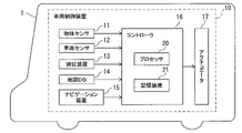
- FIG. 1 is a diagram showing an example of a schematic configuration of a vehicle equipped with a vehicle control device according to an embodiment.
- the host vehicle 1 includes a vehicle control device 10 that controls travel of the host vehicle 1 .
- the vehicle control device 10 detects the driving environment around the vehicle 1 using a sensor, and assists the driving of the vehicle 1 based on the surrounding driving environment.
- the driving support control for the own vehicle 1 by the vehicle control device 10 may include, for example, autonomous driving control for automatically driving the own vehicle 1 without the involvement of the driver. Further, the driving support control by the vehicle control device 10 may include driving support control that partially controls the steering angle, driving force, or braking force of the vehicle 1 to support the driver of the vehicle 1 .
- the vehicle control device 10 includes an object sensor 11 , a vehicle sensor 12 , a positioning device 13 , a map database 14 , a navigation device 15 , a controller 16 and an actuator 17 .
- the map database is denoted as "map DB”
- the human-machine interface is denoted as "HMI”.
- the object sensor 11 includes a plurality of sensors for detecting objects around the vehicle 1, such as a laser radar, millimeter wave radar, sonar, camera, LIDAR (Light Detection and Ranging, Laser Imaging Detection and Ranging) mounted on the vehicle 1. It has different types of object detection sensors.
- the vehicle sensor 12 is mounted on the own vehicle 1 and detects various information (vehicle signals) obtained from the own vehicle 1 .
- the vehicle sensors 12 include, for example, a vehicle speed sensor that detects the running speed (vehicle speed) of the own vehicle 1, a wheel speed sensor that detects the rotational speed of each tire, and three sensors that detect acceleration (including deceleration) in three axial directions.
- An axial acceleration sensor (G sensor) a steering angle sensor that detects the steering angle (including the steering angle), a gyro sensor that detects the angular velocity generated in the vehicle 1, a yaw rate sensor that detects the yaw rate, and an accelerator opening of the vehicle.
- An accelerator sensor for detection and a brake sensor for detecting the amount of brake operation by the driver are included.
- the positioning device 13 has a global positioning system (GNSS) receiver, receives radio waves from a plurality of navigation satellites, and measures the current position of the vehicle 1 .
- a GNSS receiver may be, for example, a global positioning system (GPS) receiver or the like.
- the positioning device 13 may be, for example, an inertial navigation device.
- the map database 14 may store high-precision map data (hereinafter simply referred to as "high-precision map”) suitable as a map for automatic driving.
- a high-precision map is map data with higher precision than map data for navigation (hereinafter simply referred to as a "navigation map”), and includes more detailed lane-by-lane information than road-by-road information.
- a high-definition map includes lane node information indicating a reference point on a lane reference line (for example, a central line within a lane) and lane link information indicating a section of a lane between lane nodes as information for each lane. including.
- the lane node information includes the identification number of the lane node, the position coordinates, the number of connected lane links, and the identification number of the connected lane link.
- the lane link information includes the lane link identification number, lane type, lane width, lane boundary line type, lane shape, lane marking line shape, and lane reference line shape.
- the high-precision map further includes the types and positional coordinates of features such as traffic lights, stop lines, signs, buildings, utility poles, curbs, crosswalks, etc. that exist on or near the lane, and lane nodes corresponding to the positional coordinates of the features. including feature information such as the identification number of the lane and the identification number of the lane link.
- features such as traffic lights, stop lines, signs, buildings, utility poles, curbs, crosswalks, etc. that exist on or near the lane, and lane nodes corresponding to the positional coordinates of the features.
- feature information such as the identification number of the lane and the identification number of the lane link.
- the navigation device 15 recognizes the current position of the own vehicle using the positioning device 13 and acquires map information for the current position from the map database 14 .
- the navigation device 15 sets a road-by-road route to the destination input by the passenger (hereinafter sometimes referred to as a "navigation route"), and provides road guidance to the passenger according to this navigation route.
- the navigation device 15 also outputs information on the navigation route to the controller 16 .
- the controller 16 may automatically drive the host vehicle so as to travel along the navigation route during autonomous travel control.
- the controller 16 is an electronic control unit (ECU: Electronic Control Unit) that controls the running of the own vehicle 1 .
- Controller 16 includes a processor 20 and peripheral components such as storage device 21 .
- the processor 20 may be, for example, a CPU (Central Processing Unit) or an MPU (Micro-Processing Unit).
- the storage device 21 may include a semiconductor storage device, a magnetic storage device, an optical storage device, or the like.
- the storage device 21 may include memories such as registers, cache memory, ROM (Read Only Memory) and RAM (Random Access Memory) used as main storage devices.
- the functions of the controller 16 to be described below are implemented, for example, by the processor 20 executing a computer program stored in the storage device 21 .
- the controller 16 may be formed of dedicated hardware (for example, programmable logic device such as FPGA (Field-Programmable Gate Array)) for executing each information processing described below.
- FPGA Field-Programmable Gate Array
- the actuator 17 operates the steering wheel, accelerator opening, and brake device of the own vehicle 1 according to the control signal from the controller 16 to cause the vehicle behavior of the own vehicle 1 .
- the actuator 17 includes a steering actuator, an accelerator opening actuator, and a brake control actuator.
- the steering actuator controls the steering direction and amount of steering of the vehicle 1 .
- the accelerator opening actuator controls the accelerator opening of the vehicle 1 .
- the brake control actuator controls the braking operation of the brake system of the host vehicle 1 .
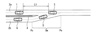
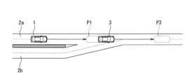
- FIG. 2A is an explanatory diagram of a problem of conventional inter-vehicle distance control.
- the vehicle 1 is traveling on the first lane 2a and the second lane 2b joins the first lane 2a in the merging section Sm in front of the vehicle 1 .
- the first lane 2a may be the main lane and the second lane 2b may be the merging lane, or the second lane 2b may be the main lane and the first lane 2a may be the merging lane.
- Positions Ps and Pe are the start point and end point of the merging section Sm, respectively.
- the host vehicle 1 performs inter-vehicle distance control for following the preceding vehicle 3 traveling in front of the host vehicle 1 on the first lane 2a. That is, vehicle speed control is performed to maintain the inter-vehicle distance to the preceding vehicle 3 at the target inter-vehicle distance.
- vehicle speed control is performed to maintain the inter-vehicle distance to the preceding vehicle 3 at the target inter-vehicle distance.
- the vehicle to be followed by inter-vehicle distance control may be referred to as a "target vehicle”.
- the inter-vehicle distance between the preceding vehicle 3 and the own vehicle 1 becomes the target inter-vehicle distance L1, and the vehicle speed V of the own vehicle 1 is controlled so that the vehicle travels at a preset set speed or less.
- the first lane 2a and the second lane 2b are shielded by a wall 4 or the like. Therefore, when the first other vehicle 5 on the second lane 2b is traveling diagonally in front of the own vehicle 1, even before the merging lane and the main road reach the merging point, It is easy to detect the first other vehicle 5 from the vehicle 1 . However, the following vehicle 6 of the first other vehicle 5 is difficult to detect from the own vehicle 1 because of the wall 4 . Therefore, as shown in FIG. 2A, the own vehicle 1 and the following vehicle 6 are in a side-by-side state, and when the own vehicle 1 and the following vehicle 6 reach the merging point, the own vehicle 1 immediately detects the following vehicle 6.
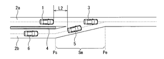
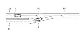
- FIG. 2B is an explanatory diagram of an example of the vehicle control method of the embodiment.
- the controller 16 controls that the first other vehicle 5 traveling in the second lane 2b that merges with the first lane 2a in which the own vehicle 1 travels ahead of the own vehicle 1 is obliquely ahead of the own vehicle 1. is running.
- the controller 16 determines that the distance between the vehicle 1 and the preceding vehicle 3 is longer than the first target inter-vehicle distance L1 in the vehicle speed control that maintains the inter-vehicle distance.
- the vehicle speed of the own vehicle 1 is controlled so that the inter-vehicle distance between the own vehicle 1 and the first other vehicle 5 is shortened.
- the inter-vehicle distance between the own vehicle 1 traveling on the first lane 2a and the first other vehicle 5 traveling on the second lane 2b is, for example, the first lane 2a (or the second lane 2b). It is defined as the distance in the longitudinal direction from the rear end position of the first other vehicle 5 to the front end position of the own vehicle 1 .
- the controller 16 sets the inter-vehicle distance between the own vehicle 1 and the first other vehicle 5 shorter than the first target inter-vehicle distance L1
- a second target inter-vehicle distance L2, which is shorter than the first target inter-vehicle distance L1 is set as the target value of
- the inter-vehicle distance between the host vehicle 1 and the first other vehicle 5 is set to the second target inter-vehicle distance L2.
- the vehicle speed of the own vehicle 1 may be controlled.
- the own vehicle 1 that has reached the vicinity of the merging point becomes the first other vehicle.
- the following vehicle 6 of 5 is detected, the own vehicle 1 is likely to be positioned ahead of the following vehicle 6 .
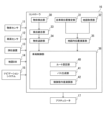
- FIG. 3 is a block diagram of an example of the functional configuration of the controller 16.
- the controller 16 includes an object detection unit 30, an own vehicle position estimation unit 31, a map acquisition unit 32, a detection integration unit 33, an object tracking unit 34, an intra-map position calculation unit 35, and a vehicle control unit 36. .
- the object detection unit 30 Based on the detection signal of the object sensor 11, the object detection unit 30 detects the position, attitude, size, speed, etc. of objects around the vehicle 1, such as vehicles (automobiles and motorcycles), pedestrians, and obstacles. To detect.
- the object detection unit 30 outputs a detection result representing the two-dimensional position, posture, size, speed, etc. of an object, for example, in a zenith view (also referred to as a plan view) in which the vehicle 1 is viewed from the air.
- a zenith view also referred to as a plan view
- the vehicle position estimator 31 calculates the absolute position of the vehicle 1, that is, the position of the vehicle 1 with respect to a predetermined reference point, based on odometry using the measurement results of the positioning device 13 and the detection results of the vehicle sensor 12. , attitude and velocity.
- the map acquisition unit 32 acquires map information indicating the structure of the road on which the vehicle 1 travels from the map database 14 .
- the map acquisition unit 32 may acquire map information from an external map data server using a communication device.
- a detection integration unit 33 integrates a plurality of detection results obtained by the object detection unit 30 from each of a plurality of object detection sensors, and outputs one two-dimensional position, orientation, size, speed, etc. for each object. do. Specifically, from the behavior of the object obtained from each of the object detection sensors, the most rational behavior of the object with the least error is calculated after considering the error characteristics of each of the object detection sensors. Specifically, by using a known sensor fusion technique, detection results obtained by a plurality of types of sensors are comprehensively evaluated to obtain more accurate detection results.
- the object tracking section 34 tracks the object detected by the object detection section 30 . Specifically, based on the detection result integrated by the detection integration unit 33, the identity of the object between different times is verified (associated) from the behavior of the object output at different times, and the Behavior such as velocity of an object is predicted based on the correspondence.
- the in-map position calculation unit 35 estimates the position and orientation of the vehicle 1 on the map from the absolute position of the vehicle 1 obtained by the vehicle position estimation unit 31 and the map information obtained by the map acquisition unit 32. do.
- the in-map position calculation unit 35 also identifies the road on which the vehicle 1 is traveling and the first lane 2a of the road on which the vehicle 1 is traveling, and determines the position of the vehicle 1 in the first lane 2a.
- a lateral position (vehicle width direction position, lane lateral position) is calculated.
- the vehicle control unit 36 based on the prediction result of the behavior of the object by the object tracking unit 34, the calculation result of the position and attitude of the own vehicle 1 by the in-map position calculation unit 35, and the input of the passenger (for example, the driver), Driving the actuator 17 controls the running of the own vehicle 1 .
- the vehicle control unit 36 includes a route setting unit 40 , a path generation unit 41 and a control command value calculation unit 42 .
- the route setting unit 40 calculates the current position of the vehicle 1 calculated by the in-map position calculation unit 35 and the destination input by the occupant (or based on the navigation route set by the navigation device 15).
- a target route (hereinafter simply referred to as “route”) for each lane on which the vehicle 1 should travel is set.
- This route is a target route that is statically set, and is set based on the lane shape of the high-definition map stored in the map database 14 and the lane boundary line shape detected by the object sensor 11 . For example, the center of the lane of the road on which the vehicle travels from the current position to the destination may be set as the route.
- the path generation unit 41 determines whether or not the vehicle 1 performs a driving action such as lane change, and based on the determination result, determines a target path (hereinafter simply referred to as "path") that the vehicle 1 should travel. set.
- This path is dynamically set according to the driving behavior of the own vehicle 1. For example, when the own vehicle 1 is caused to change lanes according to traffic conditions, the path generation unit 41 changes the lane from the lane before the lane change. Based on the vehicle model of the vehicle 1, a movement route along which the vehicle 1 moves to the next lane is generated. Conversely, when the host vehicle 1 is not caused to change lanes, a path that matches the route is generated.
- the control command value calculator 43 calculates a control command value (a steering command value or a vehicle speed command value) such that the own vehicle 1 moves along the path P generated by the path generator 41 while maintaining a distance from surrounding objects. Calculate The control command value calculation unit 43 calculates a vehicle speed command value for the own vehicle 1 based on the distance to the preceding vehicle and the relative speed and relative acceleration with respect to the preceding vehicle. Then, based on the vehicle speed command value and the path P, the target position, attitude, speed and curvature of the own vehicle at each time t+i ⁇ dt (where i is an integer from 1 to N) from the current time t until t+N ⁇ dt seconds later. The target travel trajectory of the own vehicle 1 is calculated by performing calculations for N steps.
- a control command value a steering command value or a vehicle speed command value
- the control command value calculation unit 43 calculates acceleration/deceleration and steering angle command values so that the vehicle 1 maintains a distance from surrounding objects and approaches the target travel trajectory as much as possible.
- Such control can be realized, for example, by a general obstacle avoidance algorithm such as optimal control using a potential function based on the distance to the obstacle.
- the margin to the obstacle set by the obstacle avoidance control is a limit value set so as not to get too close to the obstacle, and is often narrower than the general sense of the passenger. Therefore, when generating the target travel trajectory, the control command value calculation unit 43 calculates the vehicle speed command value so as to keep a wide distance from the target vehicle to be tracked by inter-vehicle distance control. As a result, the final vehicle speed command value and steering command value are controlled so as not to approach the preceding vehicle too much.
- the inter-vehicle distance control executed by the control command value calculation unit 43 will be described.
- the control command value calculation unit 43 identifies a target vehicle to be followed by inter-vehicle distance control.
- the control command value calculation unit 43 predicts the position of the other vehicle after a predetermined prediction time width T seconds, based on the motion state such as the position, speed and acceleration of the other vehicle estimated by the object tracking unit 34 .
- the amount of movement D for T seconds is calculated from the speed and acceleration, and the position advanced by the amount of movement D along the lane from the current position of the other vehicle is calculated as the predicted position of the other vehicle.
- P3 in FIG. 4A shows an example of the predicted position of the second other vehicle 3 traveling in front of the host vehicle 1 on the first lane 2a.
- P1 in FIGS. 4A to 4C indicates the predicted position of the own vehicle 1 after T seconds.
- P5 in FIG. 4B shows an example of the predicted position of the first other vehicle 5 traveling diagonally ahead of the own vehicle 1 on the second lane 2b.
- P7 in FIG. 4C shows an example of the predicted position T seconds later of the third other vehicle 7 traveling in the adjacent lane 2c of the first lane 2a.
- the fourth other vehicle 8 in FIG. 4C is stopped on the second lane 2b, and the amount of movement of the fourth other vehicle 8 from the current time to T seconds later is zero.
- the control command value calculation unit 43 determines whether or not these other vehicles 3, 5, 7 and 8 are to be followed by inter-vehicle distance control. (That is, it is determined whether or not the other vehicles 3, 5, 7 and 8 are target vehicles). Specifically, when the host vehicle 1 travels forward along the first lane 2a from the predicted position P1 of the own vehicle 1, the control command value calculation unit 43 determines that the predicted position of the other vehicle T seconds later is The other vehicle is identified as the target vehicle when positioned on the route. If the predicted position of the other vehicle after T seconds is not on the travel route of the own vehicle 1, it is determined that the other vehicle is not the target vehicle.
- the predicted position P3 of the second other vehicle 3 is located on the traveling route of the host vehicle 1.
- the control command value calculator 43 determines that the second other vehicle 3 is the target vehicle.
- the control command value calculation unit 43 may determine that the preceding vehicle on the first lane 1a on which the own vehicle 1 is traveling is targeted.
- the predicted position P5 of the first other vehicle 5 is located on the traveling route of the own vehicle 1 . Therefore, the control command value calculator 43 determines that the first other vehicle 5 is the target vehicle.
- the control command value calculation unit 43 calculates the distance d1 from the own vehicle 1 to the confluence point of the first lane 2a and the second lane 2b, and the distance d1 from the first other vehicle 5 traveling on the second lane 2b to the confluence point. , and when the distance d2 is shorter than the distance d1, it may be determined that the first other vehicle 5 is the target vehicle.
- the predicted position P7 of the third other vehicle 7 is not located on the traveling route of the own vehicle 1.
- the control command value calculation unit 43 determines that the third other vehicle 7 and the fourth other vehicle 8 are not target vehicles.
- T the response to the merging target vehicle (eg, the first other vehicle 5) will be delayed, requiring rapid acceleration and deceleration.
- T the vehicle distance control is started for the target vehicle that is merging even though there is a distance to the merging point, which may cause the occupants to feel uncomfortable.
- the control command value calculation unit 43 determines that the other vehicle determined to be the target vehicle (the first other vehicle 5 and the second other vehicle 3 in the examples of FIGS. It is determined whether or not the vehicle is another vehicle on the lane that merges into the first lane 2a. For example, if the current positions of the first other vehicle 5 and the second other vehicle 3 are located in the same lane as the current position of the own vehicle 1, it is determined that the other vehicle is not on the lane that merges into the first lane 2a, If the vehicle is not in the same lane, it is determined that the other vehicle is on the lane that merges into the first lane 2a. In the example of FIGS. 4A to 4C, the first other vehicle 5 is determined to be another vehicle on the lane that merges into the first lane 2a, and the second other vehicle 3 is not another vehicle on the lane that merges into the first lane 2a. I judge.
- the control command value calculation unit 43 calculates a distance between vehicles other than other vehicles on the lane that merges into the first lane 2a (the second other vehicle 3 on the first lane 2a in the example of FIGS. 4A to 4C).
- a target inter-vehicle distance for distance control is set to a first target inter-vehicle distance L1, which is a standard (normal) inter-vehicle distance.
- the first target vehicle-to-vehicle distance L1 is a vehicle-to-vehicle distance that does not make the passenger (for example, the driver) feel uneasy, and may have a length that is proportional to the vehicle speed.
- the first target inter-vehicle distance L1 may be set by the above formula (1).
- the control command value calculation unit 43 performs inter-vehicle distance control for following another vehicle on the lane that merges into the first lane 2a (in the example of FIGS. 4A to 4C, the first other vehicle 5 on the second lane 2b).
- the target inter-vehicle distance is set to a second target inter-vehicle distance L2 that is shorter than the first target inter-vehicle distance L1.
- the undetected following vehicle 6 is detected as shown in FIG. 2B.
- the vehicle 1 is likely to be positioned in front of the .
- the second target inter-vehicle distance L2 may be set to a value within a range equal to or greater than an inter-vehicle distance lower limit value Lmin and equal to or less than an inter-vehicle distance upper limit value Lmax, which will be exemplified below.
- the inter-vehicle distance lower limit value Lmin is the shortest inter-vehicle distance at which the host vehicle can follow the deceleration of the preceding vehicle, and is, for example, approximately the same distance as the obstacle margin set in the above-described obstacle avoidance control.
- the inter-vehicle distance lower limit value Lmin is designed in consideration of the maneuverability and safety factor of the own vehicle 1 .
- the second target inter-vehicle distance L2 is shorter than the inter-vehicle distance lower limit value Lmin, when the first other vehicle 5 enters the first lane 2a, the distance between the host vehicle 1 and the first other vehicle 5 is As it gets closer, evasive action is required. In general, such an avoidance action may give the occupants of the own vehicle 1 and other surrounding vehicles a sense of uneasiness.
- the inter-vehicle distance upper limit value Lmax is set to prevent a situation in which the following vehicle 6 of the first other vehicle 5 and the host vehicle 1 arrive at the merging point side by side.
- the second target inter-vehicle distance L2 between the own vehicle 1 and the first other vehicle 5 is preferably about half the inter-vehicle distance between the first other vehicle 5 and the following vehicle 6 .
- the inter-vehicle distance between the first other vehicle 5 and the following vehicle 6 is a standard inter-vehicle distance.
- the vehicle speed of the first other vehicle 5 instead of the vehicle speed of the own vehicle 1.
- FIG. For example, when the first other vehicle 5 on the second lane 2b is traveling at a lower speed than the vehicle speed on the first lane 2a, the following vehicle 6 may be approaching the first other vehicle 5.
- the own vehicle 1 can easily be positioned in front of the following vehicle 6 even when the first other vehicle 5 is slow. Become.
- the control command value calculation unit 43 performs inter-vehicle control using the target inter-vehicle distance set for the target vehicle as described above. For example, the control command value calculation unit 43 sets the vehicle speed command value V of the host vehicle so that the inter-vehicle distances between all the specified target vehicles and the host vehicle 1 are equal to or greater than the target inter-vehicle distance set for each target vehicle. can be calculated. Specifically, an evaluation function F such as the following equation (3) may be defined, and the vehicle speed command value V that minimizes the evaluation function F may be calculated by optimization calculation.
- Lr i is the target inter-vehicle distance set for the target vehicle i
- L i is the current inter-vehicle distance between the target vehicle i and the own vehicle 1
- V i is the target vehicle i is the speed
- Vr is the set vehicle speed
- WL is the weight of the inter-vehicle distance
- WV is the weight of the set vehicle speed.
- the first term of the evaluation function F increases when the inter-vehicle distance to the target vehicle i is shorter than the target inter-vehicle distance Lr i , and is 0 when the inter-vehicle distance is longer than the target inter-vehicle distance Lr.
- the inter-vehicle distances to all the target vehicles i are optimized to be equal to or greater than the respective target inter-vehicle distances Lri .
- the evaluation function F includes a cost that increases as the inter-vehicle distance between the first other vehicle 5 and the own vehicle 1 becomes shorter than the second target inter-vehicle distance L2, and It includes the sum of costs that increase as the inter-vehicle distance to the vehicle 1 becomes shorter than the first target inter-vehicle distance L1.
- the second term of the evaluation function F increases as the difference between the vehicle speed of the own vehicle 1 and the set vehicle speed Vr increases. As a result, when the distance between the target vehicle i and the subject vehicle 1 is sufficiently long, the vehicle speed V is accelerated or decelerated so as to approach the set vehicle speed Vr.
- control command value calculation unit 43 sets the target distance to the first other vehicle 5 for a while after the first other vehicle 5 changes from the second lane 2b to the first lane 2a in front of the host vehicle 1.
- the distance (that is, the target inter-vehicle distance in inter-vehicle distance control for which the first other vehicle is to be tracked) may be maintained at the second target inter-vehicle distance L2.
- the target inter-vehicle distance to the first other vehicle 5 may be maintained at the second target inter-vehicle distance L2.
- the target inter-vehicle distance to the first other vehicle 5 is set to the second target inter-vehicle distance. Change from L2 to first target inter-vehicle distance L1.
- control command value calculation unit 43 calculates the inter-vehicle distance between the own vehicle 1 and the first other vehicle 5 from a state in which the inter-vehicle distance between the own vehicle 1 and the first other vehicle 5 is shorter than the second target inter-vehicle distance L2.
- the deceleration when extending to the second target inter-vehicle distance L2 may be limited.
- the deceleration may be limited to be smaller than the upper limit of deceleration allowed when inter-vehicle distance control is performed to follow the preceding vehicle 3 on the first lane 2a.
- control command value calculation unit 43 calculates the inter-vehicle distance between the own vehicle 1 and the first other vehicle 5 from a state in which the inter-vehicle distance between the own vehicle 1 and the first other vehicle 5 is longer than the second target inter-vehicle distance L2.
- the upper limit of the absolute value of the rate of change of the vehicle speed when shortening to the second target inter-vehicle distance L2 is changed from the state where the inter-vehicle distance between the own vehicle 1 and the first other vehicle 5 is shorter than the second target inter-vehicle distance L2 to the own vehicle It may be set to a value larger than the upper limit of the absolute value of the rate of change of the vehicle speed when the inter-vehicle distance between 1 and the first other vehicle 5 is extended to the second target inter-vehicle distance L2.
- the distance between the own vehicle 1 and the first other vehicle 5 is The distance becomes shorter and easier. Therefore, when the own vehicle 1 reaches the merging point, the own vehicle 1 is likely to be positioned ahead of the following vehicle 6 of the first other vehicle 5 .
- the inter-vehicle distance between the own vehicle 1 and the first other vehicle 5 is set to the second target inter-vehicle distance.
- the responsiveness to start the control for shortening to L2 is increased, and after detecting that the inter-vehicle distance between the own vehicle 1 and the first other vehicle 5 is shorter than the second target inter-vehicle distance L2, the distance between the own vehicle 1 and the first other vehicle is detected.
- the responsiveness to start the control for extending the inter-vehicle distance from the vehicle 5 to the second target inter-vehicle distance L2 may be set low.
- the responsiveness to start the control for shortening the inter-vehicle distance between the own vehicle 1 and the first other vehicle 5 to the second target inter-vehicle distance L2 is set to the second target distance between the own vehicle 1 and the first other vehicle 5.
- the responsiveness may be higher than the responsiveness to start the control to extend to the inter-vehicle distance L2.
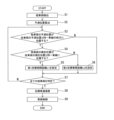
- FIG. 5 is a flowchart of an example of the vehicle control method of the embodiment.
- the object tracking unit 34 detects motion states such as positions, velocities, and accelerations of other vehicles around the host vehicle 1 .
- the control command value calculator 43 calculates the predicted position of the other vehicle after the predicted time width T seconds.
- each of the other vehicles detected by the object tracking unit 34 is selected one by one. It is determined whether or not there is, and the target inter-vehicle distance is set for the target vehicle.
- step S3 the control command value calculation unit 43 determines whether or not the predicted position of the vehicle of interest is located in front of the vehicle 1 in the same lane as the predicted position of the vehicle 1 after T seconds. If the predicted position of the target vehicle is located ahead of the predicted position of the own vehicle 1 in the same lane (S3: Y), it is determined that the target vehicle is the target vehicle, and the process proceeds to step S4. If the predicted position of the target vehicle is not located in front of the predicted position of the own vehicle 1 in the same lane (S3: N), it is determined that the target vehicle is not the target vehicle, and the process proceeds to step S7.
- step S ⁇ b>4 the control command value calculator 43 determines whether or not the current position of the vehicle of interest is in the same lane as the current position of the own vehicle 1 . If the current position of the vehicle of interest is in the same lane as the current position of the own vehicle 1 (S4: Y), the process proceeds to step S5. If the current position of the vehicle of interest is not in the same lane as the current position of the vehicle 1 (S4: N), the process proceeds to step S6. In step S5, the control command value calculator 43 sets the target inter-vehicle distance to the target vehicle to the first target inter-vehicle distance L1. After that, the process proceeds to step S7. In step S6, the control command value calculator 43 sets the second target inter-vehicle distance L2 as the target inter-vehicle distance for the vehicle of interest. After that, the process proceeds to step S7.
- step S7 the control command value calculation unit 43 determines whether or not all the other vehicles detected by the object tracking unit 34 have been determined in step S3. If all other vehicles are determined (S7: Y), the process proceeds to step S8. If there are other vehicles that have not been judged yet (S7: N), one of these other vehicles that have not been judged is selected as the vehicle of interest, and the process returns to step S3.
- step S8 the control command value calculation unit 43 calculates the vehicle speed command value of the host vehicle 1 using the target inter-vehicle distance set for the target vehicle.
- step S9 the control command value calculator 43 controls the vehicle speed of the host vehicle 1 by driving the accelerator opening actuator and the brake control actuator of the actuator 17 based on the calculated vehicle speed command value. Processing then ends.
- the controller 16 determines whether or not a first other vehicle traveling in a second lane that merges with the first lane in which the vehicle 1 is traveling in front of the vehicle 1 is traveling diagonally in front of the vehicle 1 . and when it is determined that the first other vehicle is running diagonally ahead of the own vehicle 1, the inter-vehicle distance between the preceding vehicle running ahead of the own vehicle 1 on the first lane is maintained.
- the vehicle speed of the own vehicle 1 is set so that the front-rear distance from the rear end position of the first other vehicle to the front end position of the own vehicle 1 in the front-rear direction of the first lane is shorter than the first target inter-vehicle distance in the vehicle speed control.
- the own vehicle 1 that has reached the vicinity of the merging point detects the following vehicle of the first other vehicle
- the own vehicle 1 is likely to be positioned ahead of the following vehicle.
- the controller 16 determines whether a predetermined time has elapsed, whether the own vehicle 1 has traveled a predetermined distance, and whether the first lane and the second lane have been reached.
- the vehicle speed of the own vehicle 1 is controlled so that the inter-vehicle distance between the first other vehicle and the own vehicle 1 becomes shorter than the first target inter-vehicle distance until the own vehicle 1 passes the end point of the confluence section with the , after the elapse of a predetermined time, the own vehicle 1 has traveled a predetermined distance, or the own vehicle 1 has passed the end point, the inter-vehicle distance between the own vehicle 1 and the first other vehicle becomes the first target inter-vehicle distance.
- the controller 16 determines that the first other vehicle is running obliquely ahead of the host vehicle 1, the controller 16 sets a second target inter-vehicle distance that is shorter than the first target inter-vehicle distance as the target value of the longitudinal distance. Then, the vehicle speed of the own vehicle 1 may be controlled so that the distance in the longitudinal direction becomes the second target inter-vehicle distance. As a result, the vehicle speed of the host vehicle 1 can be controlled so that the longitudinal distance is shorter than the first target inter-vehicle distance.
- the controller 16 sets the deceleration when extending the distance in the longitudinal direction to the second target inter-vehicle distance so that it becomes smaller than the allowable upper limit of deceleration in the vehicle speed control for maintaining the inter-vehicle distance to the preceding vehicle. may be restricted to Further, the controller 16 sets the upper limit of the rate of change in vehicle speed when the distance in the longitudinal direction is shortened to the second target inter-vehicle distance when extending the inter-vehicle distance between the host vehicle 1 and the first other vehicle to the second target inter-vehicle distance. may be set to a value larger than the upper limit of the rate of change of the vehicle speed.
- the responsiveness to start the vehicle speed control for shortening the longitudinal distance to the second target inter-vehicle distance may be made higher than the responsiveness to start the vehicle speed control for extending the longitudinal distance to the second target inter-vehicle distance.
- the controller 16 calculates half the product of the vehicle speed of the first other vehicle and the standard headway time as the inter-vehicle distance upper limit value, and allows the own vehicle 1 to follow the deceleration of the preceding vehicle.
- a process of setting a second target inter-vehicle distance to a distance equal to or greater than the inter-vehicle distance lower limit value and equal to or less than the inter-vehicle distance upper limit value set in advance as the shortest inter-vehicle distance may be executed.
- the inter-vehicle distance between the own vehicle 1 and the first other vehicle is reduced to half the inter-vehicle distance between the first other vehicle and the following vehicle. It becomes easier to: As a result, even when the inter-vehicle distance between the first other vehicle and the following vehicle is shorter than the standard inter-vehicle distance, the own vehicle 1 can reach the merging point before the following vehicle.
- the second target inter-vehicle distance By setting the second target inter-vehicle distance to a value equal to or greater than the inter-vehicle distance lower limit value, it is possible to prevent the host vehicle 1 from approaching the first other vehicle excessively even if the first other vehicle changes lanes to the first lane. . As a result, the anxiety felt by the driver of the own vehicle 1 or the first other vehicle can be reduced.
Abstract
Description
本発明は、自車両が走行する車線と他車両が走行する他車線とが自車両の前方で合流する合流区間において、自車両や他車両の運転者が感じる不安感を軽減するように自車両の速度を調整することを目的とする。 However, the space between the merging lane and the main road may be blocked by a wall or the like until just before the merging point. Therefore, when another vehicle on another lane merging with the own vehicle travels diagonally ahead of the own vehicle, it is easy to detect the other vehicle from the own vehicle. It can be difficult to detect. In this way, when the following vehicle and the own vehicle arrive at the merging point in a side-by-side state while the following vehicle cannot be detected, the own vehicle rapidly decelerates or accelerates immediately after the following vehicle is detected, and the following vehicle is detected. It becomes necessary to adjust the relative front-rear relationship with the following vehicle. The same applies to following vehicles. As a result, the occupants of the own vehicle and the following vehicle may feel uneasy.
The present invention is to reduce the anxiety felt by the drivers of the own vehicle and the other vehicle in a merging section where the lane in which the own vehicle is traveling and the other lane in which the other vehicle is traveling are merged in front of the own vehicle. The purpose is to adjust the speed of
本発明の目的及び利点は、特許請求の範囲に示した要素及びその組合せを用いて具現化され達成される。前述の一般的な記述及び以下の詳細な記述の両方は、単なる例示及び説明であり、特許請求の範囲のように本発明を限定するものでないと解するべきである。 According to the invention, in a merging section where the lane in which the own vehicle is traveling and the other lane in which the other vehicle is traveling merge in front of the own vehicle, the driver of the own vehicle and the other vehicle can reduce the sense of anxiety felt by the drivers of the own vehicle and the other vehicle. You can adjust the speed of your vehicle.
The objects and advantages of the invention may be realized and attained by means of the elements and combinations pointed out in the appended claims. It is to be understood that both the foregoing general description and the following detailed description are exemplary and explanatory only and are not restrictive of the invention as claimed.
図1は、実施形態の車両制御装置を搭載する車両の概略構成の一例を示す図である。自車両1は、自車両1の走行を制御する車両制御装置10を備える。車両制御装置10は、センサによって自車両1の周囲の走行環境を検出し、周囲の走行環境に基づいて自車両1の走行を支援する。車両制御装置10による自車両1の走行支援制御は、例えば、運転者が関与せずに自動で自車両1を走行させる自律走行制御を含んでよい。また、車両制御装置10による走行支援制御は、自車両1の操舵角、駆動力又は制動力を部分的に制御して、自車両1の運転者を支援する運転支援制御を含んでもよい。 (composition)
FIG. 1 is a diagram showing an example of a schematic configuration of a vehicle equipped with a vehicle control device according to an embodiment. The
物体センサ11は、自車両1に搭載されたレーザレーダやミリ波レーダ、ソナー、カメラ、LIDAR(Light Detection and Ranging、Laser Imaging Detection and Ranging)など、自車両1の周辺の物体を検出する複数の異なる種類の物体検出センサを備える。 The
The
地図データベース14は、自動運転用の地図として好適な高精度地図データ(以下、単に「高精度地図」という。)を記憶してよい。高精度地図は、ナビゲーション用の地図データ(以下、単に「ナビ地図」という)よりも高精度の地図データであり、道路単位の情報よりも詳細な車線単位の情報を含む。例えば、高精度地図は車線単位の情報として、車線基準線(例えば車線内の中央の線)上の基準点を示す車線ノードの情報と、車線ノード間の車線の区間態様を示す車線リンクの情報を含む。車線ノードの情報は、その車線ノードの識別番号、位置座標、接続される車線リンク数、接続される車線リンクの識別番号を含む。車線リンクの情報は、その車線リンクの識別番号、車線の種類、車線の幅員、車線境界線の種類、車線の形状、車線区分線の形状、車線基準線の形状を含む。高精度地図は更に、車線上又はその近傍に存在する信号機、停止線、標識、建物、電柱、縁石、横断歩道等の地物の種類及び位置座標と、地物の位置座標に対応する車線ノードの識別番号及び車線リンクの識別番号等の地物の情報を含む。 The
The
いま、第1車線2a上を自車両1が走行しており、自車両1の前方の合流区間Smにおいて第2車線2bが第1車線2aに合流する状況を想定する。例えば、第1車線2aが本線で第2車線2bが合流車線であってもよく、第2車線2bが本線で第1車線2aが合流車線であってもよい。位置PsとPeはそれぞれ合流区間Smの開始地点と終了地点である。
自車両1は、第1車線2a上で自車両1の前方を走行する先行車両3を追従対象とする車間距離制御を実施している。すなわち、先行車両3との間の車間距離を目標車間距離に維持する車速制御を実施している。
以下の説明において、車間距離制御の追従対象の車両を「対象車両」と表記することがある。
車間距離制御では、先行車両3と自車両1との車間距離が目標車間距離L1となり、且つ予め設定された設定速度以下で走行するように自車両1の車速Vが制御される。目標車間距離L1は、標準的な車間距離として予め定義された値に設定される。自車両の車速をVとし、標準的な車頭時間(Time Headway)をNとすると、例えば目標車間距離L1は、次式(1)によって設定してよい。
L1=V×N …(1)
標準的な車頭時間Nは、例えば1.0~2.0秒であり、より好ましくは1.5~1.8秒である。 Next, an example of control of the
Assume that the
The
In the following description, the vehicle to be followed by inter-vehicle distance control may be referred to as a "target vehicle".
In inter-vehicle distance control, the inter-vehicle distance between the preceding
L1=V×N (1)
A standard headway time N is, for example, 1.0 to 2.0 seconds, more preferably 1.5 to 1.8 seconds.
このため、図2Aに示すように自車両1と後続車両6とが横並びの状態となり、そのまま自車両1と後続車両6が合流地点に到達すると、自車両1は、後続車両6を検出した直後に急減速又は急加速を行って、自車両1と後続車両6との相対的な前後関係を調整する必要が生じる。後続車両6も同様である。この結果、自車両1や後続車両6の乗員に不安感を与える虞がある。 The
Therefore, as shown in FIG. 2A, the
第1他車両5が自車両1の斜め前方を走行していると判定した場合に、コントローラ16は、先行車両3との間の車間距離を維持する車速制御における第1目標車間距離L1よりも、自車両1と第1他車両5との間の車間距離が短くなるように自車両1の車速を制御する。 FIG. 2B is an explanatory diagram of an example of the vehicle control method of the embodiment. In the vehicle control method of the embodiment, the
When determining that the first
例えば、自車両1と第1他車両5との間の車間距離を第1目標車間距離L1よりも短くするために、コントローラ16は、自車両1と第1他車両5との間の車間距離の目標値として、第1目標車間距離L1よりも短い第2目標車間距離L2を設定し、自車両1と第1他車両5との間の車間距離が第2目標車間距離L2となるように、自車両1の車速を制御してもよい。 Here, the inter-vehicle distance between the
For example, in order to make the inter-vehicle distance between the
物体検出部30は、物体センサ11の検出信号に基づいて、自車両1の周辺の物体、例えば車両(自動車や自動二輪車)、歩行者、障害物などの位置、姿勢、大きさ、速度などを検出する。物体検出部30は、例えば自車両1を空中から眺める天頂図(平面図ともいう)において、物体の2次元位置、姿勢、大きさ、速度などを表現する検出結果を出力する。 The functions of the
Based on the detection signal of the
物体追跡部34は、物体検出部30によって検出された物体を追跡する。具体的には、検出統合部33により統合された検出結果に基づいて、異なる時刻に出力された物体の挙動から、異なる時刻間における物体の同一性の検証(対応付け)を行い、かつ、その対応付けを基に、物体の速度などの挙動を予測する。 A
The
車両制御部36は、物体追跡部34による物体の挙動の予測結果と、地図内位置演算部35による自車両1の位置及び姿勢の演算結果と、乗員(例えば運転者)の入力に基づいて、アクチュエータ17を駆動して自車両1の走行を制御する。車両制御部36は、ルート設定部40と、パス生成部41と、制御指令値演算部42を備える。 The in-map
The
このため制御指令値演算部43は、目標走行軌道を生成する際、車間距離制御の追従対象となる対象車両との距離を広く保つように車速指令値を算出する。これにより、最終的な車速指令値や操舵指令値が先行車両に近づきすぎないように制御される。 The control command value calculation unit 43 calculates acceleration/deceleration and steering angle command values so that the
Therefore, when generating the target travel trajectory, the control command value calculation unit 43 calculates the vehicle speed command value so as to keep a wide distance from the target vehicle to be tracked by inter-vehicle distance control. As a result, the final vehicle speed command value and steering command value are controlled so as not to approach the preceding vehicle too much.
図4BのP5は、第2車線2b上で自車両1の斜め前方を走行する第1他車両5の予測位置の一例を示す。
図4CのP7は、第1車線2aの隣接車線2cを走行する第3他車両7のT秒後の予測位置の一例を示す。図4Cの第4他車両8は第2車線2b上で停車していており、現在時刻からT秒後までの第4他車両8の移動量は0である。 P3 in FIG. 4A shows an example of the predicted position of the second
P5 in FIG. 4B shows an example of the predicted position of the first
P7 in FIG. 4C shows an example of the predicted position T seconds later of the third
図4Bの例では、第1他車両5の予測位置P5は自車両1の進行ルート上に位置する。このため制御指令値演算部43は、第1他車両5が対象車両であると判定する。なお、制御指令値演算部43は、自車両1から第1車線2aと第2車線2bとの合流地点までの距離d1と、第2車線2b上を走行する第1他車両5から合流地点までの距離d2とを比較して、距離d2が距離d1よりも短い場合に第1他車両5が対象車両であると判定してもよい。
図4Cの例では、第3他車両7の予測位置P7は自車両1の進行ルート上に位置しない。第4他車両8は移動しないため、第4他車両8のT秒後の予測位置も自車両1の進行ルート上に位置しない。このため制御指令値演算部43は、第3他車両7と第4他車両8は対象車両でないと判定する。 In the example of FIG. 4A, the predicted position P3 of the second
In the example of FIG. 4B , the predicted position P5 of the first
In the example of FIG. 4C, the predicted position P7 of the third
予測時間幅Tは、周辺車両が将来的に合流するかどうかを計算するための長さであり、10秒~20秒程度が望ましい。例えばT=10秒とした場合、10秒以内に合流する可能性のある車だけが抽出される。Tが短すぎると、合流してくる対象車両(例えば第1他車両5)に対する反応が遅くなり、急な加減速が必要になる。一方、Tが長すぎると、合流地点まで距離があるにもかかわらず、合流してくる対象車両に対して車間制御を始めるため、乗員に違和感を与える可能性がある。 As a result, not only the second
The predicted time width T is a length for calculating whether or not surrounding vehicles will join in the future, and is preferably about 10 to 20 seconds. For example, if T=10 seconds, only cars that are likely to merge within 10 seconds are extracted. If T is too short, the response to the merging target vehicle (eg, the first other vehicle 5) will be delayed, requiring rapid acceleration and deceleration. On the other hand, if T is too long, the vehicle distance control is started for the target vehicle that is merging even though there is a distance to the merging point, which may cause the occupants to feel uncomfortable.
制御指令値演算部43は、第1車線2aへ合流する車線上の他車両(図4A~図4Cの例では第2車線2b上の第1他車両5)を追従対象とする車間距離制御の目標車間距離を、第1目標車間距離L1よりも短い第2目標車間距離L2に設定する。第1車線2aへ合流する車線上の他車両との車間距離を、第1目標車間距離L1よりも短い第2目標車間距離L2とすることで、図2Bに示すように未検知の後続車両6の前方に自車両1が位置にいる状態となり易くなる。 The control command value calculation unit 43 calculates a distance between vehicles other than other vehicles on the lane that merges into the
The control command value calculation unit 43 performs inter-vehicle distance control for following another vehicle on the lane that merges into the
車間距離下限値Lminは、自車両が先行車両の減速に追従しうる最短の車間距離であり、例えば、前述の障害物回避制御で設定される障害物とのマージンと同程度の距離である。車間距離下限値Lminは、自車両1の運動性能や安全率などを考慮して設計される。
第2目標車間距離L2が車間距離下限値Lminよりも短い場合には、第1他車両5が第1車線2aに進入するときに、自車両1と第1他車両5との間の距離が近くなるため回避動作が必要になる。このような回避動作は一般的に、自車両1や周囲の他車両の乗員に不安感を与える可能性がある。 For example, the second target inter-vehicle distance L2 may be set to a value within a range equal to or greater than an inter-vehicle distance lower limit value Lmin and equal to or less than an inter-vehicle distance upper limit value Lmax, which will be exemplified below.
The inter-vehicle distance lower limit value Lmin is the shortest inter-vehicle distance at which the host vehicle can follow the deceleration of the preceding vehicle, and is, for example, approximately the same distance as the obstacle margin set in the above-described obstacle avoidance control. The inter-vehicle distance lower limit value Lmin is designed in consideration of the maneuverability and safety factor of the
When the second target inter-vehicle distance L2 is shorter than the inter-vehicle distance lower limit value Lmin, when the first
標準的な車間距離は、車速×(標準的な車頭時間N)により近似できるので、例えば次式(2)によって車間距離上限値Lmaxを設定してよい。
Lmax=Vi×N×0.5 …(2)
なお、式(2)においてViは、第1他車両5の車速である。 The inter-vehicle distance upper limit value Lmax is set to prevent a situation in which the following
Since the standard inter-vehicle distance can be approximated by vehicle speed×(standard headway time N), the inter-vehicle distance upper limit value Lmax may be set by the following equation (2), for example.
Lmax=V i ×N×0.5 (2)
Note that V i in Expression (2) is the vehicle speed of the first

評価関数Fの第1項は、対象車両iとの車間距離が、目標車間距離Lriよりも短くなると増加し目標車間距離Lrよりも長ければ0である。全ての対象車両iについて算出したコストを総和することで、全ての対象車両iとの車間距離が各々の目標車間距離Lri以上となるように最適化される。
例えば図2A及び図2Bの例では、評価関数Fは、第1他車両5と自車両1との車間距離が第2目標車間距離L2より短くなるほど増加するコストと、第2他車両3と自車両1との車間距離が第1目標車間距離L1より短くなるほど増加するコストとの総和を含んでいる。
評価関数Fの第2項は、自車両1の車速と設定車速Vrとの差が大きいほど大きくなる。これにより、対象車両iと自車両1との車間距離が十分離れているときは、車速Vが設定車速Vrに近づくように加減速する。 In equation (4), Lr i is the target inter-vehicle distance set for the target vehicle i, L i is the current inter-vehicle distance between the target vehicle i and the
The first term of the evaluation function F increases when the inter-vehicle distance to the target vehicle i is shorter than the target inter-vehicle distance Lr i , and is 0 when the inter-vehicle distance is longer than the target inter-vehicle distance Lr. By totaling the costs calculated for all the target vehicles i, the inter-vehicle distances to all the target vehicles i are optimized to be equal to or greater than the respective target inter-vehicle distances Lri .
For example, in the examples of FIGS. 2A and 2B , the evaluation function F includes a cost that increases as the inter-vehicle distance between the first
The second term of the evaluation function F increases as the difference between the vehicle speed of the
例えば、第1他車両5が自車両1の前方において車線変更した後、所定時間が経過するか、自車両1が所定距離走行するか、自車両1が合流区間Smの終了地点Peを通過するまで、第1他車両5に対する目標車間距離を第2目標車間距離L2に維持してもよい。その後、所定時間が経過するか、自車両1が所定距離走行するか、自車両1が合流区間Smの終了地点Peを通過した後に、第1他車両5に対する目標車間距離を第2目標車間距離L2から第1目標車間距離L1へ変更する。 Note that the control command value calculation unit 43 sets the target distance to the first
For example, after the first
また例えば制御指令値演算部43は、自車両1と第1他車両5との車間距離が第2目標車間距離L2よりも長い状態から、自車両1と第1他車両5との車間距離を第2目標車間距離L2まで短縮する場合の車速の変化率の絶対値の上限を、自車両1と第1他車両5との車間距離が第2目標車間距離L2よりも短い状態から、自車両1と第1他車両5との車間距離を第2目標車間距離L2まで延長する場合の車速の変化率の絶対値の上限よりも大きな値に設定してもよい。
以上のように自車両1と第1他車両5との車間距離を第2目標車間距離に調整する際の加速度及び減速度を設定することで、自車両1と第1他車両5との車間距離が短くなり易くなる。このため、自車両1が合流地点に到達したときに、第1他車両5の後続車両6よりも自車両1の方が前方に位置し易くなる。 Further, for example, the control command value calculation unit 43 calculates the inter-vehicle distance between the
Further, for example, the control command value calculation unit 43 calculates the inter-vehicle distance between the
By setting the acceleration and deceleration for adjusting the inter-vehicle distance between the
例えば、自車両1と第1他車両5との車間距離を第2目標車間距離L2まで短縮する制御を開始する応答性を、自車両1と第1他車両5との車間距離を第2目標車間距離L2まで延長する制御を開始する応答性よりも高くしてもよい。
以上のように自車両1と第1他車両5との車間距離を第2目標車間距離に調整する際の制御開始の応答性を設定することで、自車両1と第1他車両5との車間距離が短くなり易くなる。このため、自車両1が合流地点に到達したときに、第1他車両5の後続車両6よりも自車両1の方が前方に位置し易くなる。 Further, after detecting that the inter-vehicle distance between the
For example, the responsiveness to start the control for shortening the inter-vehicle distance between the
By setting the responsiveness of control start when adjusting the inter-vehicle distance between the
図5は、実施形態の車両制御方法の一例のフローチャートである。
ステップS1において物体追跡部34は、自車両1の周囲の他車両の位置、速度及び加速度などの運動状態を検出する。
ステップS2において制御指令値演算部43は、予測時間幅T秒後の他車両の予測位置を算出する。
ステップS3~S7では、物体追跡部34が検出した他車両の各々を1つずつ選択し、選択した他車両(以下「注目車両」と表記する)が車間距離制御の追従対象となる対象車両であるかを判定し、対象車両に対して目標車間距離を設定する。 (motion)
FIG. 5 is a flowchart of an example of the vehicle control method of the embodiment.
In step S<b>1 , the
In step S2, the control command value calculator 43 calculates the predicted position of the other vehicle after the predicted time width T seconds.
In steps S3 to S7, each of the other vehicles detected by the
ステップS5において制御指令値演算部43は、注目車両に対する目標車間距離を第1目標車間距離L1に設定する。その後に処理はステップS7へ進む。
ステップS6において制御指令値演算部43は、注目車両に対する目標車間距離を第2目標車間距離L2に設定する。その後に処理はステップS7へ進む。 In step S<b>4 , the control command value calculator 43 determines whether or not the current position of the vehicle of interest is in the same lane as the current position of the
In step S5, the control command value calculator 43 sets the target inter-vehicle distance to the target vehicle to the first target inter-vehicle distance L1. After that, the process proceeds to step S7.
In step S6, the control command value calculator 43 sets the second target inter-vehicle distance L2 as the target inter-vehicle distance for the vehicle of interest. After that, the process proceeds to step S7.
ステップS8において制御指令値演算部43は、対象車両に対して設定した目標車間距離を用いて自車両1の車速指令値を演算する。
ステップS9において制御指令値演算部43は、演算した車速指令値に基づいてアクチュエータ17のアクセル開度アクチュエータと、ブレーキ制御アクチュエータを駆動し、自車両1の車速を制御する。その後に処理は終了する。 In step S7, the control command value calculation unit 43 determines whether or not all the other vehicles detected by the
In step S8, the control command value calculation unit 43 calculates the vehicle speed command value of the
In step S9, the control command value calculator 43 controls the vehicle speed of the
(1)コントローラ16は、自車両1の前方において自車両1が走行する第1車線へ合流する第2車線を走行する第1他車両が、自車両1の斜め前方を走行しているか否かを判定する処理と、第1他車両が自車両1の斜め前方を走行していると判定した場合、第1車線上で自車両1の前方を走行する先行車両との間の車間距離を維持する車速制御における第1目標車間距離よりも、第1車線の前後方向における第1他車両の後端位置から自車両1の先端位置までの前後方向距離が短くなるように、自車両1の車速を制御する処理と、を実行する。
これにより、合流地点に付近に到達した自車両1が第1他車両の後続車両を検出した時点で、自車両1が後続車両よりも前方に位置し易くなる。この結果、合流地点に到達したときに、後続車両が自車両1の後方のスペースに入りやすくなる。このため、後続車両が第1車線へ進入するスペースを空けるために急減速又は急加速をする必要がなくなるので、自車両や後続車両の運転者が感じる不安感を軽減できる。 (Effect of Embodiment)
(1) The
As a result, when the
これにより、第1他車両の後続車両が、第1他車両に続いて自車両1の前方に車線変更するのを抑制できる。
(3)コントローラ16は、第1他車両が自車両1の斜め前方を走行していると判定した場合、前後方向距離の目標値として第1目標車間距離よりも短い第2目標車間距離を設定し、前後方向距離が第2目標車間距離となるように自車両1の車速を制御してよい。
これにより、前後方向距離が第1目標車間距離よりも短くなるように自車両1の車速を制御できる。 (2) After the first other vehicle has changed lanes to the first lane in front of the
As a result, it is possible to prevent the vehicle following the first other vehicle from changing lanes in front of the
(3) When the
As a result, the vehicle speed of the
また、コントローラ16は、前後方向距離を第2目標車間距離まで短縮する場合の車速の変化率の上限を、自車両1と第1他車両との車間距離を第2目標車間距離まで延長する場合の車速の変化率の上限よりも大きな値に設定してもよい。
また、前後方向距離を第2目標車間距離まで短縮する車速制御を開始する応答性を、前後方向距離を第2目標車間距離まで延長する車速制御を開始する応答性よりも高くしてもよい。
これにより、自車両1と第1他車両との車間距離が短くなり易くなる。このため、自車両1が合流地点に到達したときに、第1他車両の後続車両よりも自車両1の方が前方に位置し易くなる。 (4) The
Further, the
Further, the responsiveness to start the vehicle speed control for shortening the longitudinal distance to the second target inter-vehicle distance may be made higher than the responsiveness to start the vehicle speed control for extending the longitudinal distance to the second target inter-vehicle distance.
As a result, the inter-vehicle distance between the
第2目標車間距離を車間距離上限値以下の値に設定することで、自車両1と第1他車両との間の車間距離を、第1他車両と後続車両との間の車間距離の半分以下にし易くなる。これにより、第1他車両と後続車両との車間距離が標準的な車間距離よりも短い場合でも、後続車両よりも先に自車両1が合流地点に到達できる。
第2目標車間距離を車間距離下限値以上の値に設定することで、第1他車両が第1車線に車線変更しても自車両1と第1他車両が過度に接近するのを防止できる。これにより自車両1や第1他車両の運転者が感じる不安感を軽減できる。 (5) The
By setting the second target inter-vehicle distance to a value equal to or less than the inter-vehicle distance upper limit value, the inter-vehicle distance between the
By setting the second target inter-vehicle distance to a value equal to or greater than the inter-vehicle distance lower limit value, it is possible to prevent the
Claims (8)
- 自車両の前方において前記自車両が走行する第1車線へ合流する第2車線を走行する第1他車両が、前記自車両の斜め前方を走行しているか否かを判定する処理と、
前記第1他車両が前記自車両の斜め前方を走行していると判定した場合、前記第1車線上で前記自車両の前方を走行する先行車両との間の車間距離を維持する車速制御における第1目標車間距離よりも、前記第1車線の前後方向における前記第1他車両の後端位置から前記自車両の先端位置までの前後方向距離が短くなるように、前記自車両の車速を制御する処理と、
をコントローラに実行させることを特徴とする車両制御方法。 a process of determining whether or not a first other vehicle traveling in a second lane that merges with a first lane in which the own vehicle travels in front of the own vehicle is traveling diagonally in front of the own vehicle;
In vehicle speed control for maintaining the inter-vehicle distance to a preceding vehicle traveling ahead of the own vehicle on the first lane when it is determined that the first other vehicle is traveling diagonally ahead of the own vehicle The vehicle speed of the own vehicle is controlled such that the front-rear distance from the rear end position of the first other vehicle to the front end position of the own vehicle in the front-rear direction of the first lane is shorter than the first target inter-vehicle distance. and
A vehicle control method characterized by causing a controller to execute: - 前記コントローラは、
前記第1他車両が前記自車両前方において前記第1車線へ車線変更した後、所定時間が経過するか、前記自車両が所定距離走行するか、前記第1車線と前記第2車線との合流区間の終了地点を前記自車両が通過するまで、前記第1他車両と前記自車両との間の車間距離が前記第1目標車間距離よりも短くなるように前記自車両の車速を制御し、
前記所定時間が経過するか、前記自車両が前記所定距離走行するか、前記終了地点を前記自車両が通過した後に、前記自車両と前記第1他車両との間の車間距離が第1目標車間距離となるように前記自車両の車速を制御する、
請求項1に記載の車両制御方法。 The controller is
After the first other vehicle changes lanes to the first lane in front of the own vehicle, a predetermined time elapses, the own vehicle travels a predetermined distance, or the first lane and the second lane merge. controlling the vehicle speed of the own vehicle so that the inter-vehicle distance between the first other vehicle and the own vehicle is shorter than the first target inter-vehicle distance until the own vehicle passes the end point of the section;
After the predetermined time elapses, the subject vehicle travels the predetermined distance, or the subject vehicle passes the end point, the inter-vehicle distance between the subject vehicle and the first other vehicle is a first target. controlling the vehicle speed of the own vehicle so that the inter-vehicle distance is achieved;
The vehicle control method according to claim 1. - 前記コントローラは、
前記第1他車両が前記自車両の斜め前方を走行していると判定した場合、前記前後方向距離の目標値として前記第1目標車間距離よりも短い第2目標車間距離を設定し、
前記前後方向距離が前記第2目標車間距離となるように前記自車両の車速を制御する、
ことを特徴とする請求項1又は2に記載の車両制御方法。 The controller is
setting a second target inter-vehicle distance that is shorter than the first target inter-vehicle distance as a target value of the longitudinal distance when it is determined that the first other vehicle is traveling diagonally ahead of the own vehicle;
controlling the vehicle speed of the host vehicle so that the longitudinal distance becomes the second target inter-vehicle distance;
3. The vehicle control method according to claim 1, wherein: - 前記前後方向距離を前記第2目標車間距離まで延長する場合の減速度を、前記先行車両との間の車間距離を維持する車速制御における減速度の許容上限値よりも小さくなるように制限することを特徴とする請求項3に記載の車両制御方法。 limiting deceleration when extending the longitudinal distance to the second target inter-vehicle distance so as to be smaller than an allowable upper limit value of deceleration in vehicle speed control for maintaining the inter-vehicle distance to the preceding vehicle; The vehicle control method according to claim 3, characterized by:
- 前記前後方向距離を前記第2目標車間距離まで短縮する場合の車速の変化率の上限を、前記自車両と前記第1他車両との車間距離を前記第2目標車間距離まで延長する場合の車速の変化率の上限よりも大きな値に設定することを特徴とする請求項3又は4のいずれか一項に記載の車両制御方法。 The upper limit of the rate of change in vehicle speed when the longitudinal distance is reduced to the second target inter-vehicle distance is set to the vehicle speed when the inter-vehicle distance between the own vehicle and the first other vehicle is extended to the second target inter-vehicle distance. 5. The vehicle control method according to claim 3, wherein the value is set to a value larger than the upper limit of the rate of change of .
- 前記前後方向距離を前記第2目標車間距離まで短縮する車速制御を開始する応答性を、前記前後方向距離を前記第2目標車間距離まで延長する車速制御を開始する応答性よりも高くする、ことを特徴とする請求項3~5のいずれか一項に記載の車両制御方法。 making the responsiveness for starting the vehicle speed control for shortening the longitudinal distance to the second target inter-vehicle distance higher than the responsiveness for starting the vehicle speed control for extending the longitudinal distance to the second target inter-vehicle distance. The vehicle control method according to any one of claims 3 to 5, characterized by:
- 前記第1他車両の車速と標準的な車頭時間との積の2分の1を車間距離上限値として算出する処理と、
前記自車両が先行車両の減速に追従しうる最短の車間距離として予め設定した車間距離下限値以上、且つ前記車間距離上限値以下の距離を、前記第2目標車間距離として設定する処理と、
を前記コントローラに実行させることを特徴とする請求項3~6のいずれか一項に記載の車両制御方法。 A process of calculating half of the product of the vehicle speed of the first other vehicle and a standard vehicle headway time as an inter-vehicle distance upper limit value;
A process of setting a distance equal to or greater than the inter-vehicle distance lower limit value and equal to or less than the inter-vehicle distance upper limit value set in advance as the shortest inter-vehicle distance at which the own vehicle can follow the deceleration of the preceding vehicle, as the second target inter-vehicle distance;
7. The vehicle control method according to any one of claims 3 to 6, wherein the controller is caused to execute: - 自車両の前方において前記自車両が走行する第1車線へ合流する第2車線を走行する第1他車両が、前記自車両の斜め前方を走行しているか否かを判定する処理と、
前記第1他車両が前記自車両の斜め前方を走行していると判定した場合、前記第1車線上で前記自車両の前方を走行する先行車両との間の車間距離を維持する車速制御における第1目標車間距離よりも、前記第1車線の前後方向における前記第1他車両の後端位置から前記自車両の先端位置までの前後方向距離が短くなるように、前記自車両の車速を制御する処理と、
を実行するコントローラを備えることを特徴とする車両制御装置。 a process of determining whether or not a first other vehicle traveling in a second lane that merges with a first lane in which the own vehicle travels in front of the own vehicle is traveling diagonally in front of the own vehicle;
In vehicle speed control for maintaining the inter-vehicle distance to a preceding vehicle traveling ahead of the own vehicle on the first lane when it is determined that the first other vehicle is traveling diagonally ahead of the own vehicle The vehicle speed of the own vehicle is controlled such that the front-rear distance from the rear end position of the first other vehicle to the front end position of the own vehicle in the front-rear direction of the first lane is shorter than the first target inter-vehicle distance. and
A vehicle control device comprising a controller that executes:
Priority Applications (2)
| Application Number | Priority Date | Filing Date | Title |
|---|---|---|---|
| PCT/JP2021/032161 WO2023032092A1 (en) | 2021-09-01 | 2021-09-01 | Vehicle control method and vehicle control device |
| CN202180101520.XA CN117836182A (en) | 2021-09-01 | 2021-09-01 | Vehicle control method and vehicle control device |
Applications Claiming Priority (1)
| Application Number | Priority Date | Filing Date | Title |
|---|---|---|---|
| PCT/JP2021/032161 WO2023032092A1 (en) | 2021-09-01 | 2021-09-01 | Vehicle control method and vehicle control device |
Publications (1)
| Publication Number | Publication Date |
|---|---|
| WO2023032092A1 true WO2023032092A1 (en) | 2023-03-09 |
Family
ID=85410943
Family Applications (1)
| Application Number | Title | Priority Date | Filing Date |
|---|---|---|---|
| PCT/JP2021/032161 WO2023032092A1 (en) | 2021-09-01 | 2021-09-01 | Vehicle control method and vehicle control device |
Country Status (2)
| Country | Link |
|---|---|
| CN (1) | CN117836182A (en) |
| WO (1) | WO2023032092A1 (en) |
Citations (3)
| Publication number | Priority date | Publication date | Assignee | Title |
|---|---|---|---|---|
| JPH0554297A (en) * | 1991-08-22 | 1993-03-05 | Mazda Motor Corp | Automatic braking device for vehicle |
| JP2001001789A (en) * | 1999-06-23 | 2001-01-09 | Nissan Motor Co Ltd | Following distance control system |
| JP2017154614A (en) * | 2016-03-02 | 2017-09-07 | トヨタ自動車株式会社 | Vehicle travel controlling apparatus |
-
2021
- 2021-09-01 CN CN202180101520.XA patent/CN117836182A/en active Pending
- 2021-09-01 WO PCT/JP2021/032161 patent/WO2023032092A1/en active Application Filing
Patent Citations (3)
| Publication number | Priority date | Publication date | Assignee | Title |
|---|---|---|---|---|
| JPH0554297A (en) * | 1991-08-22 | 1993-03-05 | Mazda Motor Corp | Automatic braking device for vehicle |
| JP2001001789A (en) * | 1999-06-23 | 2001-01-09 | Nissan Motor Co Ltd | Following distance control system |
| JP2017154614A (en) * | 2016-03-02 | 2017-09-07 | トヨタ自動車株式会社 | Vehicle travel controlling apparatus |
Also Published As
| Publication number | Publication date |
|---|---|
| CN117836182A (en) | 2024-04-05 |
Similar Documents
| Publication | Publication Date | Title |
|---|---|---|
| US10996679B2 (en) | Method to evaluate trajectory candidates for autonomous driving vehicles (ADVs) | |
| US11809194B2 (en) | Target abnormality determination device | |
| JP6380920B2 (en) | Vehicle control device | |
| JP7295012B2 (en) | Vehicle control system and vehicle control method | |
| US11631257B2 (en) | Surroundings recognition device, and surroundings recognition method | |
| JP2017074823A (en) | Lane change support apparatus | |
| JP2020037339A (en) | Collision avoidance device | |
| JP7163729B2 (en) | vehicle controller | |
| JP2021020580A (en) | Vehicle control device, vehicle control method, and program | |
| US20210061350A1 (en) | Driving support device | |
| JPWO2018047232A1 (en) | Vehicle control device | |
| JP6892887B2 (en) | Vehicle control device and vehicle | |
| WO2020148561A1 (en) | Driving assistance method and driving assistance device | |
| WO2019008648A1 (en) | Target vehicle speed generation method and target vehicle speed generation device for driving assistance vehicle | |
| JP6331858B2 (en) | Advance vehicle overtaking support system | |
| JP6314744B2 (en) | Moving object track prediction device | |
| JP2020163967A (en) | Vehicle drive assisting system | |
| JP7435787B2 (en) | Route confirmation device and route confirmation method | |
| JP2020045038A (en) | Vehicle control method and vehicle control apparatus | |
| WO2023032092A1 (en) | Vehicle control method and vehicle control device | |
| JP7345043B2 (en) | Vehicle control method and vehicle control device | |
| WO2023100355A1 (en) | Vehicle control method and vehicle control device | |
| JP7458797B2 (en) | Driving support method and driving support device | |
| JP2020023214A (en) | Driving support method and driving support device | |
| WO2021234427A1 (en) | Travel assistance method and travel assistance device |
Legal Events
| Date | Code | Title | Description |
|---|---|---|---|
| 121 | Ep: the epo has been informed by wipo that ep was designated in this application |
Ref document number: 21955272 Country of ref document: EP Kind code of ref document: A1 |
|
| WWE | Wipo information: entry into national phase |
Ref document number: 2023544884 Country of ref document: JP |
|
| REG | Reference to national code |
Ref country code: BR Ref legal event code: B01A Ref document number: 112024002804 Country of ref document: BR |
|
| WWE | Wipo information: entry into national phase |
Ref document number: 2021955272 Country of ref document: EP |
|
| ENP | Entry into the national phase |
Ref document number: 2021955272 Country of ref document: EP Effective date: 20240402 |