WO2023026871A1 - Heating control device and control program, fluid heating unit, heating cycle device, and vehicle air conditioning device comprising same - Google Patents
Heating control device and control program, fluid heating unit, heating cycle device, and vehicle air conditioning device comprising same Download PDFInfo
- Publication number
- WO2023026871A1 WO2023026871A1 PCT/JP2022/030698 JP2022030698W WO2023026871A1 WO 2023026871 A1 WO2023026871 A1 WO 2023026871A1 JP 2022030698 W JP2022030698 W JP 2022030698W WO 2023026871 A1 WO2023026871 A1 WO 2023026871A1
- Authority
- WO
- WIPO (PCT)
- Prior art keywords
- heating
- temperature
- coolant
- heater
- amount
- Prior art date
Links
- 238000010438 heat treatment Methods 0.000 title claims abstract description 280
- 239000012530 fluid Substances 0.000 title claims abstract description 43
- 238000004378 air conditioning Methods 0.000 title abstract description 3
- 239000002826 coolant Substances 0.000 claims abstract description 155
- 238000001514 detection method Methods 0.000 claims abstract description 25
- XLYOFNOQVPJJNP-UHFFFAOYSA-N water Substances O XLYOFNOQVPJJNP-UHFFFAOYSA-N 0.000 claims description 35
- 230000003247 decreasing effect Effects 0.000 claims description 33
- 230000007423 decrease Effects 0.000 claims description 20
- 238000011144 upstream manufacturing Methods 0.000 claims description 8
- 238000010586 diagram Methods 0.000 description 13
- 238000000034 method Methods 0.000 description 9
- 230000017525 heat dissipation Effects 0.000 description 6
- 230000009467 reduction Effects 0.000 description 5
- 230000008859 change Effects 0.000 description 4
- 239000007788 liquid Substances 0.000 description 4
- 239000000203 mixture Substances 0.000 description 4
- 230000005855 radiation Effects 0.000 description 4
- LYCAIKOWRPUZTN-UHFFFAOYSA-N Ethylene glycol Chemical compound OCCO LYCAIKOWRPUZTN-UHFFFAOYSA-N 0.000 description 3
- 239000004148 curcumin Substances 0.000 description 3
- 238000005485 electric heating Methods 0.000 description 3
- 230000020169 heat generation Effects 0.000 description 3
- PEDCQBHIVMGVHV-UHFFFAOYSA-N Glycerine Chemical compound OCC(O)CO PEDCQBHIVMGVHV-UHFFFAOYSA-N 0.000 description 2
- 230000002159 abnormal effect Effects 0.000 description 2
- 238000013459 approach Methods 0.000 description 2
- 238000002485 combustion reaction Methods 0.000 description 2
- 238000001816 cooling Methods 0.000 description 2
- 230000000694 effects Effects 0.000 description 2
- 238000012886 linear function Methods 0.000 description 2
- 229910052751 metal Inorganic materials 0.000 description 2
- 239000002184 metal Substances 0.000 description 2
- 238000013021 overheating Methods 0.000 description 2
- 230000000630 rising effect Effects 0.000 description 2
- 229910000838 Al alloy Inorganic materials 0.000 description 1
- 239000004677 Nylon Substances 0.000 description 1
- 238000009835 boiling Methods 0.000 description 1
- 238000012790 confirmation Methods 0.000 description 1
- 239000000470 constituent Substances 0.000 description 1
- 238000012937 correction Methods 0.000 description 1
- 230000006866 deterioration Effects 0.000 description 1
- 238000009429 electrical wiring Methods 0.000 description 1
- 238000000605 extraction Methods 0.000 description 1
- 235000011187 glycerol Nutrition 0.000 description 1
- 229920006015 heat resistant resin Polymers 0.000 description 1
- 238000012986 modification Methods 0.000 description 1
- 230000004048 modification Effects 0.000 description 1
- 229910001120 nichrome Inorganic materials 0.000 description 1
- 229920001778 nylon Polymers 0.000 description 1
- 238000001556 precipitation Methods 0.000 description 1
- 230000008569 process Effects 0.000 description 1
- 238000012546 transfer Methods 0.000 description 1
- 238000012795 verification Methods 0.000 description 1
Images


Classifications
-
- B—PERFORMING OPERATIONS; TRANSPORTING
- B60—VEHICLES IN GENERAL
- B60H—ARRANGEMENTS OF HEATING, COOLING, VENTILATING OR OTHER AIR-TREATING DEVICES SPECIALLY ADAPTED FOR PASSENGER OR GOODS SPACES OF VEHICLES
- B60H1/00—Heating, cooling or ventilating [HVAC] devices
- B60H1/22—Heating, cooling or ventilating [HVAC] devices the heat being derived otherwise than from the propulsion plant
-
- F—MECHANICAL ENGINEERING; LIGHTING; HEATING; WEAPONS; BLASTING
- F24—HEATING; RANGES; VENTILATING
- F24D—DOMESTIC- OR SPACE-HEATING SYSTEMS, e.g. CENTRAL HEATING SYSTEMS; DOMESTIC HOT-WATER SUPPLY SYSTEMS; ELEMENTS OR COMPONENTS THEREFOR
- F24D13/00—Electric heating systems
- F24D13/04—Electric heating systems using electric heating of heat-transfer fluid in separate units of the system
-
- F—MECHANICAL ENGINEERING; LIGHTING; HEATING; WEAPONS; BLASTING
- F24—HEATING; RANGES; VENTILATING
- F24D—DOMESTIC- OR SPACE-HEATING SYSTEMS, e.g. CENTRAL HEATING SYSTEMS; DOMESTIC HOT-WATER SUPPLY SYSTEMS; ELEMENTS OR COMPONENTS THEREFOR
- F24D3/00—Hot-water central heating systems
Definitions
- the present disclosure relates to a heating control device and control program, a fluid heating unit, a heating cycle device, and a vehicle air conditioner including the same.
- Patent Document 1 Conventionally, there has been known a vehicle air conditioner using a hot water type heating device that performs heating using hot water (see Patent Document 1, for example).
- the vehicle air conditioner of Patent Document 1 includes a first switch and a second switch, and sets a target temperature of hot water when activated by the second switch to a target temperature of hot water when activated by the first switch. By setting the value lower than the target temperature of , it is possible to obtain a comfortable heating temperature during heating when the temperature in the passenger compartment is high.
- Patent Document 3 As a method of controlling the amount of power supplied to an electric heater, a method of supplying DC power obtained from a battery with duty control by an inverter is known (see Patent Document 3, for example).
- the flow rate of the heat medium flowing through the electric heating type hot water heating device must be adjusted to a predetermined flow rate. There are things that are happening.
- the heat medium is supplied at a predetermined flow rate and a predetermined power is supplied, the heat medium reaches a predetermined temperature when it flows out of the hot water heating device.
- the heat medium is not supplied at a predetermined flow rate due to some cause such as pump failure, the heat medium at a predetermined temperature cannot be obtained unless the amount of power supplied is appropriately reduced.
- the flow rate of the heat medium is less than the predetermined flow rate, supplying power set to heat the predetermined flow rate may overheat the heat medium and generate a large amount of water vapor.
- many devices are placed in the front compartment of the vehicle where the hot water heating device is located (the space formed in front of the vehicle interior where the passengers board). In addition, it is not always possible to set the flow direction of the heat medium flowing through the heater to flow upward.
- the surface temperature of the exothermic heater exposed in the water vapor area becomes higher than the temperature during normal operation (during heat generation when in contact with the liquid heat medium).
- the components of the heat medium may be precipitated unintentionally, or the liquid heat medium may come into contact with the liquid heat medium, resulting in a sudden increase in the pressure of the steam.
- the inventors of the present application diligently studied a technique for properly grasping that the amount of heat medium supplied is less than a predetermined flow rate, and reducing the amount of electric power to be supplied. came to creation.
- the present disclosure provides a heating control device and a control program, a fluid heating unit, a heating cycle device, and a vehicle air conditioner including the same that can appropriately grasp that the amount of heat medium supplied is less than a predetermined flow rate. for the purpose.
- the heating control device has a coolant inlet (10b), a flow path (10c) and an outlet (10a), and the inlet (10b) and the outlet (10a) are configured to circulate flow.
- Heating mounted in a fluid heating unit (10) comprising a first temperature sensing device (51) arranged and a transistor (5) supplying power to said heater (4) by switching operation to control said transistor
- the heating control device (6) controls the switching operation of the transistor (5) and changes the on-off duty ratio of the transistor (5) to control the heater (4).
- the temperature rise rate of the coolant downstream of the heater (4) stores a temperature map 850 (851, 852) and has an initial heating mode that is executed from the start of energization of the heater (4) until the temperature of the coolant reaches a predetermined temperature.
- the temperature rise rate of the coolant is calculated based on the temperature of the coolant detected by the first temperature detection device (51), and based on the temperature rise map 850 (851, 852) and deriving an estimated flow rate of the coolant corresponding to the calculated rate of temperature rise.
- the heating control device (6) preferably makes the heating amount smaller than the heating amount at the set flow rate when the estimated flow rate is less than the set flow rate. Overheating of the heater can be suppressed by reducing the amount of power to be supplied.
- the heating control device (6) preferably reduces the heating amount as the coolant temperature rises from the low temperature side to the high temperature side.
- the heating control device (6) is mounted in a vehicle air conditioner and estimates an estimated heat release amount of the coolant in a radiator (7) provided in the circulation flow path (2).
- the estimated flow rate is preferably a value corrected based on the estimated amount of heat release. The flow rate can be estimated more accurately.
- the heating control device (6) has a derating mode executed after the initial heating mode, and in the derating mode, the transistor (5 ), the on-off duty ratio of the transistor (5) is changed to adjust the heating amount by the heater (4), and the heating amount control profile 100 (100A to 100E) is It is a function indicating the relationship between the coolant temperature and the amount of heating by the heater (4), and the amount of heating decreases as the temperature rises from the low temperature side to the high temperature side across the target temperature of the coolant.
- the slope of (100A to 100E) is preferably more negative than the slope of the heating amount control profile 100 (100A to 100E) at any temperature in the first region (111A). It is possible to reach the target temperature early and control the temperature with a small fluctuation with respect to the target temperature.
- a fluid heating unit includes a housing (14) having an inlet (10b), a flow path (10c) and an outlet (10a) for the coolant, and a housing (14) disposed in the flow path (10c) to generate heat by energization.
- a heater (4) that heats the coolant by heating the coolant
- a first temperature detection device (51) arranged downstream of the heater (4)
- a transistor (5) that supplies power to the heater (4) by a switching operation.
- a heating control device (6) controls the switching operation of the transistor (5).
- the fluid heating unit according to the present invention includes a form in which the flow path (10c) extends substantially horizontally. Even in a fluid heating unit in which water vapor may stagnate, it is possible to quickly detect a decrease in flow rate and reduce the effects of water vapor stagnation.
- the fluid heating unit (10) preferably further comprises a second temperature detection device (52) upstream of the heater (4).
- the flow rate can be estimated more accurately.
- a heating cycle device includes a circulation flow path (2), coolant filled in the circulation flow path (2), and a pump (3) for circulating the coolant in the circulation flow path (2).
- a fluid heating unit (10) according to the present invention for controlling the temperature of the coolant; and a radiator (7) for dissipating heat from the coolant, wherein the coolant is supplied to the heater (4) in the fluid heating unit (10). ) is heated by being energized by the transistor (5).
- a vehicle air conditioner according to the present invention is a vehicle air conditioner (900) equipped with a heating cycle device (1) according to the present invention and mounted on a vehicle, wherein the vehicle can be driven by an electric motor.
- the vehicle air conditioner (900) has a temperature control unit (901) for adjusting the temperature of the air supplied to the vehicle interior, and the radiator (7) is provided inside the temperature control unit (901). It is characterized by being an arranged hot water type heat exchanger.
- a control program according to the present invention is characterized by causing the heating control device (6) according to the present invention to execute the initial heating mode.
- a heating control device and a control program, a fluid heating unit, a heating cycle device, and a vehicle air conditioner including the same, which can appropriately grasp that the amount of heat medium supplied is less than a predetermined flow rate. can provide.
- FIG. 10 is a diagram showing a second example of a heating amount control profile;
- FIG. 10 is a diagram showing a third example of a heating amount control profile;
- FIG. 10 is a diagram showing a fourth example of a heating amount control profile;
- FIG. 11 is a diagram showing a fifth example of a heating amount control profile;
- FIG. 10 is a diagram showing a first example of a profile excluded from the heating amount control profile;
- FIG. 10 is a diagram showing a second example of a profile excluded from the heating amount control profile;
- FIG. 10 is a diagram showing a third example of a profile excluded from the heating amount control profile;
- FIG. 10 is a diagram showing a fourth example of a profile excluded from the heating amount control profile;
- FIG. 1 is a block diagram showing an example of a heating cycle device according to this embodiment and a vehicle air conditioner including the same.
- the heating control device 6 according to the present embodiment has a coolant inlet 10b, a flow path 10c, and an outlet 10a, and the inlet 10b and the outlet 10a are connected to the circulation flow path 2;
- a heater 4 that is arranged in the flow path 10c to generate heat when energized to heat the coolant, a first temperature detection device 51 that is arranged downstream of the heater 4, and a transistor 5 that supplies power to the heater 4 by a switching operation.
- the heating control device for controlling the transistor 5, the heating control device 6 controls the switching operation of the transistor 5 to change the on-off duty ratio of the transistor 5.
- a temperature rise map is stored which shows the relationship between the rate of temperature rise of the coolant downstream of the heater 4 and the flow rate of the coolant when the amount of heat by the heater 4 is adjusted and the amount of heat by the heater 4 is a predetermined amount. and has an initial heating mode that is executed from the start of energization to the heater 4 until the temperature of the coolant reaches a predetermined temperature, and in the initial heating mode, the temperature detected by the first temperature detection device 51
- a temperature rise rate of the coolant is calculated based on the coolant temperature, and an estimated flow rate of the coolant corresponding to the calculated temperature rise rate is derived based on the temperature rise map.
- the fluid heating unit 10 includes a housing 14 having a coolant inlet 10b, a flow path 10c, and an outlet 10a, and a heater 4 arranged in the flow path 10c to heat the coolant by generating heat when energized. , a first temperature detection device 51 disposed downstream of the heater 4, a transistor 5 that supplies power to the heater 4 by switching operation, and a heating control device 6 according to the present embodiment. , controls the switching operation of the transistor 5 .
- the fluid heating unit 10 heats the coolant supplied to the radiator 7 of the vehicle air conditioner by the transistor 5 supplying power to the heater 4 and the heater 4 generating heat.
- the heating control device 6 controls the switching operation of the transistor 5, changes the on-off duty ratio of the transistor 5, and adjusts the amount of heating by the heater 4, thereby adjusting the temperature of the coolant.
- the housing 14 has a coolant channel 10c as an internal space, and allows the coolant that has flowed in from the inlet 10b to pass through to the outlet 10a.
- the housing 14 is made of metal such as aluminum alloy, or heat-resistant resin such as 6,6-nylon.
- the fluid heating unit 10 includes a mode in which the flow path 10c extends substantially horizontally.
- the substantially horizontal direction means that the flow path 10c runs substantially horizontally when the fluid heating unit 10 is mounted on the vehicle, and is a concept that includes the horizontal direction and a direction slightly inclined with respect to the horizontal direction.
- the heating control device 6 can quickly detect a decrease in the flow rate, as will be described later. Therefore, the influence of staying water vapor can be reduced.
- the fluid heating unit 10 includes a heater 4, a housing 14 containing the heater 4, and a transistor 5 arranged on the upper wall of the housing 14, like the fluid control unit described in Patent Document 2.
- the heater 4 is an electric heating element that generates heat when energized, and is not particularly limited.
- a sheathed heater in which a nichrome wire is wrapped in a metal pipe is used.
- the housing 14 has a heating chamber through which coolant flows and which houses the heater 4 .
- pre-heated coolant is introduced through the inlet 10b, and heated coolant is discharged through the outlet 10a.
- the heating chamber has a first temperature detection device 51 downstream of the heater 4 for detecting the temperature T of the coolant after heating.
- the first temperature detection device 51 is, for example, a temperature sensor.
- the first temperature detection device 51 is preferably provided near the outflow port 10a.
- the coolant Even if the temperature of the coolant varies depending on the location of the heating chamber, the coolant is mixed by concentrating at the outlet 10a when the coolant flows out of the heating chamber, and the temperature can be detected without variation. Furthermore, it is more preferable to provide the first temperature detection device 51 in the channel 10c immediately before the outlet 10a. By providing the first temperature detection device 51 upstream of the outflow port 10a, the temperature can be detected before unintended heat radiation of the coolant occurs, and the heat energy transferred from the heater 4 to the coolant can be detected with high accuracy. can be done with
- the transistor 5 is preferably an insulated gate bipolar transistor (IGBT), for example.
- Transistor 5 is electrically connected to battery 8 .
- the transistor 5 is electrically connected to the control device 6 and performs a switching operation according to a command signal from the heating control device 6 .
- the transistor 5 controls power supply to the heater 4 by switching operation. By changing the on-off duty ratio of the transistor 5, the heating amount by the heater 4 can be adjusted, and the heat amount given to the coolant can be adjusted.
- the fluid heating unit 10 includes at least the heater 4 , the transistor 5 , the heating control device 6 , and an electrical wiring 55 that connects them to form an electrical circuit with the battery 8 .
- a coolant (not shown) is liquid at room temperature, and is a heat medium, for example, dissolved in water with ethylene glycol or glycerin.
- the fluid heating unit 10 preferably further includes a second temperature detection device 52 on the upstream side of the heater 4 .
- the flow rate can be estimated more accurately.
- the heating cycle device 1 includes a circulation flow path 2, a coolant filled in the circulation flow path 2, a pump 3 that circulates the coolant in the circulation flow path 2, and a temperature control of the coolant. and a radiator 7 for dissipating heat from the coolant.
- the heating cycle device 1 is a device that generates warm air for heating in a vehicle air conditioner by exchanging heat between the coolant temperature-controlled by the fluid heating unit 10 and the air passing through the radiator 7 .
- the circulation flow path 2 includes a pipe 11 connecting an outlet 10 a of a housing 14 containing the heater 4 and a coolant inlet of the radiator 7 , and a pipe connecting a coolant outlet of the radiator 7 and the pump 3 . 12 and a pipe 13 connecting the pump 3 and the inlet 10 b of the housing 14 .
- the coolant is sent by the pump 3, introduced into the heating chamber in the housing 14 from the inlet 10b through the pipe 13, and heated by the heater 4 built in the housing 14. As shown in FIG. Subsequently, the heated coolant is led out from the outlet 10a of the housing 14, sent through the pipe 11 to the radiator 7, and radiated to heat the air for air conditioning.
- the coolant that has passed through the radiator 7 is sucked into the pump 3 through the pipe 12 and circulated.
- the radiator 7 is a hot water heat exchanger.
- the temperature rise map shows the relationship between the temperature rise rate of the coolant on the downstream side of the heater 4 and the flow rate of the coolant when the heating amount of the heater 4 is a predetermined amount.
- the rate of temperature rise of the coolant on the downstream side of the heater 4 and the coolant flow rate when the heating amount of the heater 4 is a predetermined amount will be described.
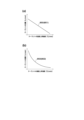
- FIG. 2 is a diagram for explaining the rate of temperature rise of the coolant.
- FIG. 2 shows graphs 801, 802, 803, and 804 showing the relationship between the elapsed time and the coolant temperature on the downstream side of the heater 4 when the heating amount of the heater 4 is 7 kW/h. is 0 L/min (0 L/h), graph 802 when the flow rate is 2 L/min (120 L/h), graph 803 when the flow rate is 5 L/min (300 L/h), Graph 804 when the flow rate is 10 L/min (600 L/h).
- These graphs 801, 802, 803 and 804 have rising portions 801a, 802a, 803a and 804a at the beginning of heating of the heater 4.
- FIG. 1 shows 0 L/min (0 L/h)
- the initial stage of heating of the heater 4 is preferably within 60 seconds from when power supply to the heater 4 is started, and more preferably within 20 to 30 seconds from when power supply to the heater 4 is started.
- the rate of temperature rise of the coolant is the slope of the tangential lines of the rising portions 801a, 802a, 803a and 804a.
- the temperature of the coolant on the downstream side of the heater 4 is the temperature detected by the first temperature detection device 51, for example.
- the coolant flow rate is the volume of coolant that flows through the circulation flow path 2 per unit time in the heating cycle device 1 .
- the temperature rise rate of the coolant differs when the flow rate of the coolant differs. More specifically, the lower the coolant flow rate, the faster the coolant temperature rise rate tends to be.
- the temperature rise map is a function of this tendency.
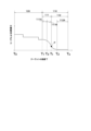
- FIG. 3 is a graph of the temperature rise map, (a) showing the first example and (b) showing the second example.
- the temperature rise map is stored in a storage unit (not shown) of the heating control device 6.
- FIG. The temperature rise map 850 (851, 852) is a function showing the relationship between the coolant temperature rise rate on the downstream side of the heater 4 and the flow rate of the coolant when the heating amount of the heater 4 is a predetermined amount.
- 3(a) and 3(b) when displayed as a graph in which the horizontal axis is the temperature rise rate of the coolant and the vertical axis is the flow rate of the coolant, the temperature rise map 850 (851, 852) is, for example, shown in FIG. 3(a) is represented by a graph such as a negative linear function 851 as shown in FIG. 3(a) or an inversely proportional function 852 as shown in FIG. 3(b).
- the heating control device 6 preferably stores a plurality of temperature rise maps for each heating amount of the heater 4 .
- the heating control device 6 uses, as temperature rise maps, a first temperature rise map for a heating amount of 100%, a second temperature rise map for a heating amount of 60%, and a third temperature rise map for a heating amount of 40%. You may remember.
- the heating amount E of the heater 4 in the initial heating mode when the estimated flow rate is the set flow rate may be referred to as 100% heating amount.
- the initial heating mode is a mode that is executed from the time T0 when energization of the heater 4 is started until T1 when the temperature of the coolant reaches a predetermined temperature (the period denoted by reference numeral 120 in FIG. 4 or FIG. 5).
- T1 when the coolant temperature reaches the predetermined temperature is preferably ⁇ target temperature Tt ⁇ -10°C, more preferably ⁇ target temperature Tt ⁇ -8°C.
- the target temperature Tt is, for example, 80-85.degree.
- the coolant temperature rise rate is calculated, for example, as follows.
- the heating control device 6 acquires the temperature of the coolant detected by the first temperature detection device 51 at predetermined intervals ⁇ t.
- X be the temperature of the coolant detected by the first temperature detection device 51 at a certain time t after the start of energization of the heater 4, and the first temperature detection device 51 detects the temperature at a time (t ⁇ t) ⁇ t before the time t.
- the temperature rise rate of the coolant at time t can be obtained by ⁇ (XX')/ ⁇ t ⁇ .
- the predetermined interval ⁇ t is not particularly limited, and is, for example, 3 to 5 seconds.
- the heating control device 6 derives an estimated coolant flow rate corresponding to the calculated temperature increase rate based on the temperature increase map. It is preferable that the work of deriving the estimated flow rate of the coolant is continued for a predetermined period of time, and that the flow rate state is low when it is determined that the derived estimated flow rate is continuously lower than the set flow rate.
- the duration of the extraction work is not particularly limited, but is, for example, 20 to 30 seconds.
- the coolant flow rate is set to a predetermined flow rate (set flow rate) such as 10 L/min, for example. It is necessary to assume a special case where the coolant is not supplied.
- the flow rate of the coolant is lower than the set flow rate during operation of the fluid heating unit 10 , boiling of the coolant may cause localized abnormal heat generation, which may affect the reliability of the fluid heating unit 10 .
- a method of estimating the coolant flow rate from the temperature difference between the upstream and downstream temperatures of the fluid heating unit 10 has been adopted.
- the temperature on the downstream side of the fluid heating unit 10 is used to detect the flow rate.
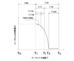
- FIG. 4 is a diagram showing an example of the relationship between the coolant temperature and the heating amount by the heater when the estimated flow rate is the set flow rate.
- the heating control device 6 maintains a predetermined heating amount E 100 even if the temperature T rises from the low temperature side to the high temperature side in the heating initial mode. is preferred.
- the amount of heating E 100 at this set flow rate is, for example, 7 kW/h.
- FIG. 5 is a diagram showing an example of the relationship between the coolant temperature and the heating amount by the heater when the estimated flow rate is less than the set flow rate.
- the heating control device 6 When the estimated flow rate is less than the set flow rate, the heating control device 6 according to the present embodiment preferably makes the heating amount E smaller than the heating amount E 100 at the set flow rate. Overheating of the heater can be suppressed by reducing the amount of power to be supplied.
- the heating control device 6 adjusts the heating amount by the heater 4 by making the on-off duty ratio of the transistor 5 smaller than the duty ratio at the set flow rate.
- the heating control device 6 preferably reduces the heating amount E as the coolant temperature rises from the low temperature side to the high temperature side.
- the form of reducing the heating amount E includes a form of stepwise reduction as shown in FIG. 5 or a form of gradual reduction (not shown). For example, when the set flow rate is 10 L/min and the estimated flow rate is 5 L/min, as shown in FIG. (eg 7 kW/h) to 60%. Next, when the coolant temperature rises from 0° C. to 20° C., the heating control device 6 reduces the heating amount E by the heater 4 to 50% of the heating amount (for example, 7 kW/h) at the set flow rate. . Next, when the coolant temperature rises from 20° C.
- the heating control device 6 reduces the heating amount E by the heater 4 to 40% of the heating amount (for example, 7 kW/h) at the set flow rate. . In this manner, the heating control device 6 performs control to decrease the heating amount E as the coolant temperature rises from the low temperature side to the high temperature side.
- the heating control device 6 preferably performs the following controls.
- the heating control device 6 calculates the rate of temperature rise of the coolant from the start of energization of the heater 4, and derives the estimated flow rate based on the temperature rise map for 100% heating amount. At this time, 100% of the electric power of the heating amount at the set flow rate is applied to the heater 4 (step 1).
- the heating control device 6 determines that the estimated flow rate is less than the set flow rate in step 1, the power application rate is reduced from 100% to 60%, for example, so that the amount of heating corresponds to the derived estimated flow rate. (Step 2).
- step 3 the actual coolant temperature rise rate under 60% heating amount and the coolant temperature rise rate in the temperature rise map at 60% heating amount are compared to determine whether the estimated flow rate derived in step 1 is appropriate. Confirm and verify whether there is an error or not (step 3). As a result of the confirmation/verification in step 3, if the error is large, the estimated flow rate (second estimated flow rate) is derived based on the temperature rise map at 60% heating amount (step 4). Next, the power application rate is changed so as to obtain a heating amount corresponding to the second estimated flow rate (step 5). In step 5, the change in application rate may be a decrease in application rate or an increase in application rate. Thereafter, steps 3 to 5 may be repeated as necessary. Such control can prevent water vapor from staying in the fluid heating unit 10 . In addition, the amount of heat radiation can be stabilized at an early stage in the radiator.
- the heating control device 6 is mounted in a vehicle air conditioner and estimates the estimated heat release amount of the coolant in the radiator 7 provided in the circulation flow path 2, and the estimated flow rate is the estimated heat release amount It is preferable that the value is corrected based on.
- the temperature of the coolant flowing into the fluid heating unit 10 tends to decrease as the amount of heat radiation from the radiator 7 increases. Therefore, as the amount of heat released by the radiator 7 increases, the temperature rise rate of the coolant becomes slower, and there is a possibility that the estimated flow rate may have an error in the direction larger than the true flow rate. Therefore, by correcting the temperature rise map by adding the factor of the amount of heat released by the radiator 7, it is possible to estimate the flow rate more accurately.
- the estimated heat release amount can be obtained, for example, as follows.
- the estimated flow rate is the amount of coolant circulating in the circulation passage 2, the temperature of the coolant downstream of the heater 4 (the temperature detected by the first temperature detection device 51), and the temperature of the coolant upstream of the heater 4 ( temperature detected by the second temperature detection device 52).
- the flow rate of air flowing into the radiator 7 (value obtained by multiplying the air volume of the blower 902 by the distribution ratio distributed to the radiator 7 side by the air mix door (not shown)), the temperature of the air flowing into the radiator 7 A (the temperature estimated by the outside air temperature, the inside air temperature, and the mixture ratio of the outside air and inside air adjusted by the intake door), the temperature of the air flowing out of the radiator 7 B (the temperature distributed to bypass the radiator 7 by the air mix door Based on the difference between temperature B and temperature A (air temperature difference upstream and downstream of the radiator 7), the radiator 7 By multiplying the flow rate of the inflowing air, the amount of heat released by the radiator per unit time may be estimated. Correction of the estimated flow rate based on the estimated amount of heat dissipation is preferably performed in the temperature rise map so that the rate of temperature rise of the coolant increases as the estimated amount of heat dissipation increases.
- the heating control device 6 has a derating mode that is executed after the initial heating mode.
- the heating amount control profile 100 (100A to 100E) Based on, the switching operation of the transistor 5 is controlled, the on-off duty ratio of the transistor 5 is changed to adjust the heating amount by the heater 4, and the heating amount control profile 100 (100A to 100E) is the coolant temperature T and It is a function showing the relationship with the heating amount E by the heater 4, and has a decreasing portion 110 in which the heating amount E decreases as the temperature T rises from the low temperature side to the high temperature side across the target temperature Tt of the coolant.
- the reduction unit 110 has a first reduction unit 111 when the temperature T is in the temperature range below the target temperature Tt, and a second reduction unit 112 when the temperature T is in the temperature range above the target temperature Tt.
- the first decreasing portion 111 and the second decreasing portion 112 have the same heating amount E at the target temperature Tt, and both the first decreasing portion 111 and the second decreasing portion 112 have a negative slope in the function.
- the first decreasing portion 111 has a first region 111A and a second region 111B on the higher temperature side than the first region 111A, and a heating amount control profile 100 (100A 100E) is preferably more negative than the slope of the heating amount control profile 100 (100A to 100E) at an arbitrary temperature in the first region 111A.
- the change in the heating amount during the period 120 during which the heating initial mode is executed is indicated by a dotted line, but as illustrated in FIG. 4 or FIG. .
- the heating control device 6 controls the switching operation of the transistor 5 based on the heating amount control profile 100 (100A to 100E) in the derating mode. As a result, the target temperature can be reached at an early stage, and control can be performed with a small change in temperature with respect to the target temperature.
- the heating amount control profile 100 is a function indicating the relationship between the coolant temperature T and the heating amount E by the heater, as shown in FIGS. 4 to 9, the heating amount control profile 100 (100A to 100E) is displayed as a graph with the coolant temperature T on the horizontal axis and the heating amount E by the heater 4 on the vertical axis.
- the coolant temperature T is preferably, for example, the temperature of the coolant discharged from the outlet 10a of the fluid heating unit 10, and the unit is, for example, degrees Celsius.
- the heating amount E by the heater 4 is, for example, a value adjusted by the on-off duty ratio of the transistor 5, and the unit is KW/h, for example.
- the decreasing portion 110 is a portion where the heating amount E decreases as the temperature T increases from the low temperature side to the high temperature side across the target temperature Tt of the coolant. 4 to 9, the temperature range from the temperature T1 at which the amount of heating E begins to decrease to the temperature Te at which the amount of heating E approaches zero or the temperature (not shown) at which the amount of heating E becomes zero. is.
- the first decreasing portion 111 has a temperature range from the temperature T1 at which the heating amount E begins to decrease in the decreasing portion 110 to the target temperature Tt or less.
- the first reduced portion 111 has a first region 111A and a second region 111B on the higher temperature side than the first region 111A.
- the boundary between the first region 111A and the second region 111B is not particularly limited. However, any temperature may be used.
- the second decreasing portion 112 is a temperature range from the target temperature Tt to a temperature Te at which the amount of heating E approaches zero, or a temperature (not shown) at which the amount of heating E becomes zero.
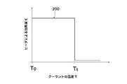
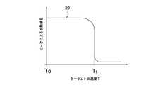
- the first decreasing portion 111 and the second decreasing portion 112 have the same heating amount E at the target temperature Tt. Therefore, as shown in FIG. 10 or 11 , the profiles 200 and 201 in which the heating amount decreases at the target temperature Tt are excluded from the heating amount control profile 100.
- FIG. FIG. 10 is a simple on/off control
- FIG. 11 is a modified example of FIG.
- the amount of heating E decreases sharply at the target temperature Tt, so temperature fluctuations with respect to the target temperature increase. This is because the coolant is radiated by the heat radiator 7, and if the amount of heat is suddenly set to "zero" after the coolant has reached the target temperature Tt, the coolant temperature T drops rapidly from the target temperature.
- both the first decreasing portion 111 and the second decreasing portion 112 have a negative slope in the function, and the heating amount control profile at an arbitrary temperature in the second region 111B
- the slope of 100 (100A to 100E) is more negative than the slope of heating amount control profile 100 (100A to 100E) at an arbitrary temperature in first region 111A.
- the target temperature can be reached early, and the fluctuation of the temperature with respect to the target temperature can be reduced.
- a profile 203 with a smaller negative magnitude than the slope at the temperature of is excluded from the heating amount control profile 100 .
- the temperature rise rate is slow and the target temperature cannot be reached early.
- the second reducing portion 112 is adapted to the amount of heat dissipation that maintains the heating amount E at a predetermined heating amount on the higher temperature side than the target temperature Tt. It is preferred to have region 112A.
- the heat radiation amount corresponding area 112A is an area in which the heating amount E is brought close to zero but not zero. It is more preferable that Te at the end of the heat dissipation corresponding region 112A is ⁇ target temperature Tt+8°C ⁇ 1°C.
- the start time T2 of the heat dissipation corresponding area 112A is preferably ⁇ target temperature Tt+4° C. ⁇ 1° C., for example.
- the radiator 7 radiates heat, and if the amount of heat is suddenly set to "zero" even though the temperature has risen and exceeded the target temperature Tt, the coolant temperature T will fall below the target temperature, leading to temperature hunting. Temperature hunting can be suppressed by providing the heat quantity corresponding region 112A.
- the temperature T at which the heating amount E is 0 is preferably 90°C. If the temperature exceeds 90°C, problems such as unintended precipitation of components dissolved in the coolant or deterioration of heat conduction due to the generation of bubbles at the interface between the coolant and the heat transfer wire may occur.
- each heating amount control profile 100 (100A to 100E) will be described in more detail.
- the heating amount control profile 100A has a decreasing portion 110 that is a curve having an inflection point P, and the temperature T at the inflection point P coincides with the target temperature Tt. contain.
- the heating amount control profile 100 (100A) of the first example reaches the target temperature Tt within 15 minutes, for example, and controls the temperature with respect to the target temperature Tt within the range ⁇ target temperature Tt ⁇ 1° C., for example. can be done. Further, since the temperature T at which the point of inflection P coincides with the target temperature Tt, it is possible to control the fluctuation of the temperature with respect to the target temperature Tt to be smaller.
- the heating amount control profile 100B includes a form in which the decreasing portion 110 is a curve having an inflection point P, and the temperature T at which the inflection point P is higher than the target temperature Tt.
- the temperature T that becomes the inflection point P is preferably more than ⁇ target temperature Tt ⁇ +0°C and +4°C or less, and more preferably ⁇ target temperature Tt ⁇ +1°C or more and +2°C or less.
- the coolant may be heated too much with respect to the target temperature.
- the heating amount control profile 100 (100B) of the second example reaches the target temperature Tt within 15 minutes, for example, and controls the temperature with respect to the target temperature Tt within the range of ⁇ target temperature Tt ⁇ 1° C., for example. can be done.
- the temperature T that becomes the inflection point P is on the higher temperature side than the target temperature Tt, it becomes easy to set the heating amount E by the heater relatively large when the coolant temperature T is the target temperature Tt.
- the vehicle air conditioner 900 in which the radiator 7 radiates a relatively large amount of heat it is possible to suitably control the fluctuation of the temperature with respect to the target temperature Tt to be small.
- the decreasing portion 110 is a curve having an inflection point P, the temperature T at which the inflection point P is lower than the target temperature Tt, and the second region 111B includes the form in the region on the lower temperature side than the inflection point P.
- the temperature T that becomes the inflection point P is preferably ⁇ target temperature Tt ⁇ -4°C or higher and lower than 0°C, and more preferably ⁇ target temperature Tt ⁇ -1°C or higher and -2°C or lower. If the temperature T that becomes the inflection point P is less than ⁇ target temperature Tt ⁇ -4° C., the time required to reach the target temperature Tt may be long.
- the first decreasing portion 111 includes a third region 111C, which is a region higher than the temperature at which the inflection point P is reached.
- the heating amount control profile 100 (100C) of the third example reaches the target temperature Tt within 15 minutes, for example, and controls the temperature with respect to the target temperature Tt within the range of ⁇ target temperature Tt ⁇ 1° C., for example. can be done.
- the temperature T that becomes the inflection point P is on the lower temperature side than the target temperature Tt, it becomes easy to set the heating amount E by the heater relatively small when the coolant temperature T is the target temperature Tt.
- the vehicle air conditioner 900 in which the amount of heat released by the radiator 7 is relatively small, it is possible to suitably control the fluctuation of the temperature with respect to the target temperature Tt to be small.
- the heating amount control profile 100D includes a form in which both the first region 111A and the second region 111B are linear functions with mutually different slopes.
- the heating amount control profile 100 (100D) of the fourth example reaches the target temperature Tt within 15 minutes, for example, and controls the temperature relative to the target temperature Tt within the range ⁇ target temperature Tt ⁇ 1° C. can be done.
- the heating amount control profile 100E includes a form in which the decreasing portion 110 is a curve with no inflection point.
- the heating amount control profile 100 (100E) of the fifth example reaches the target temperature Tt within 15 minutes, for example, and controls the temperature with respect to the target temperature Tt within the range ⁇ target temperature Tt ⁇ 1° C. can be done.
- a vehicle air conditioner 900 includes the heating cycle device 1 according to the present embodiment and is mounted on a vehicle.
- the vehicle air conditioner 900 has a temperature control unit 901 that adjusts the temperature of the air supplied to the vehicle interior, and the radiator 7 is a hot water type heat exchanger arranged inside the temperature control unit 901. It is a vessel.
- a vehicle air conditioner 900 has a blower unit 904 and a temperature control unit 901 .
- the blower unit 904 is provided with a blower 902 that blows air taken in from an inside air inlet and/or an outside air inlet (not shown) toward an air flow path 903 .
- the internal space of the temperature control unit 901 is an air flow path 903, and the hot water type heat exchanger (radiator) 7 is arranged in the air flow path 903.
- the hot water type heat exchanger (radiator) 7 is arranged in the air flow path 903.
- An air mix door (not shown) that is arranged between the device and the hot water heat exchanger 7 and adjusts the ratio of the air that passes through the hot water heat exchanger 7 and the air that bypasses the hot water heat exchanger 7 It is preferable to further have A defrost opening (not shown), a vent opening (not shown), and a foot opening (not shown) are provided at the most downstream portion of the temperature control unit 901 . Each opening is indirectly or directly connected to an air outlet (not shown) in the passenger compartment via a duct (not shown).
- Vehicles include, for example, an electric vehicle (EV) that runs only on an electric motor, a hybrid vehicle (HEV) that runs on a plurality of power sources including an electric motor and an internal combustion engine, or an internal combustion engine that only generates power and uses that power.
- EV electric vehicle
- HEV hybrid vehicle
- HEV hybrid vehicle
- the total amount of coolant in the coolant loop tends to be smaller than that of vehicles equipped with an engine. If the coolant flow rate drops due to some trouble, the heater 4 is exposed from the coolant and the surface temperature of the heater 4 becomes abnormally high.
- the heating cycle device 1 installed in the vehicle air conditioner according to the present embodiment can easily detect a decrease in the flow rate at an early stage.
- the control program causes the heating control device 6 according to this embodiment to execute the initial heating mode.
- the heating control device 6 has a storage unit (not shown) and functions as a heating control device by executing a control program read from the storage unit. Execution of the control program includes, for example, the following processes. First, the temperature of the coolant detected by the first temperature detection device 51 is detected, and the rate of temperature rise of the coolant is calculated. Then, the temperature rise map is applied to read the coolant flow rate (estimated flow rate) corresponding to the calculated coolant temperature rise rate. When the estimated flow rate is less than the set flow rate, the transistor 5 is controlled so that duty control is performed to give the heater 4 a heating amount corresponding to the estimated flow rate.
Abstract
Description
2 循環流路
3 ポンプ
4 ヒータ
5 トランジスタ
6 暖房制御装置
7 放熱器
8 バッテリ
10 流体加熱ユニット
10a 流出口
10b 流入口
10c 流路
11,12,13 配管
14 ハウジング
51 第1温度検出装置
52 第2温度検出装置
55 電気配線
100(100A~100E) 加熱量制御プロファイル
110 減少部
111 第1減少部
111A 第1領域
111B 第2領域
111C 第3領域
112 第2減少部
112A 放熱量対応領域
200,201,202,203 プロファイル
801,802,803,804 グラフ
801a,802a,803a,804a 立ち上がり部
850(851,852) 昇温マップ
900 車両用空調装置
901 温調ユニット
902 送風機
903 空気流路
904 ブロワユニット 1
Claims (11)
- クーラントの流入口(10b)、流路(10c)及び流出口(10a)を有し、かつ、前記流入口(10b)及び前記流出口(10a)が循環流路(2)に接続されるハウジング(14)と、前記流路(10c)内に配置されて通電によって発熱して前記クーラントを加熱するヒータ(4)と、該ヒータ(4)の下流側に配置される第1温度検出装置(51)と、スイッチング動作によって前記ヒータ(4)に電力を供給するトランジスタ(5)と、を備える流体加熱ユニット(10)に搭載されて前記トランジスタを制御する暖房制御装置(6)において、
前記暖房制御装置(6)は、前記トランジスタ(5)の前記スイッチング動作を制御し、前記トランジスタ(5)のオン‐オフのデューティ比を変更して前記ヒータ(4)による加熱量を調整し、かつ、前記ヒータ(4)の加熱量が所定量であるときの前記ヒータ(4)の下流側の前記クーラントの温度上昇速度と前記クーラントの流量との関係を示す昇温マップ850(851,852)を記憶しており、かつ、前記ヒータ(4)への通電開始時から前記クーラントの温度が所定温度に到達する時までの間で実行する暖房初期モードを有し、該暖房初期モードでは、前記第1温度検出装置(51)で検出された前記クーラントの温度に基づいて前記クーラントの温度上昇速度を算出し、前記昇温マップ850(851,852)に基づいて、算出された前記温度上昇速度に対応する前記クーラントの推定流量を導出することを特徴とする暖房制御装置。 A housing having a coolant inlet (10b), a flow path (10c) and an outlet (10a), wherein the inlet (10b) and the outlet (10a) are connected to a circulation flow path (2). (14), a heater (4) arranged in the flow path (10c) to generate heat when energized to heat the coolant, and a first temperature detection device arranged downstream of the heater (4) ( 51) and a transistor (5) for supplying power to said heater (4) by switching operation, in a heating control device (6) mounted in a fluid heating unit (10) for controlling said transistor,
The heating control device (6) controls the switching operation of the transistor (5) and changes the on-off duty ratio of the transistor (5) to adjust the amount of heating by the heater (4), and a temperature rise map 850 (851, 852) showing the relationship between the rate of temperature rise of the coolant on the downstream side of the heater (4) and the flow rate of the coolant when the heating amount of the heater (4) is a predetermined amount. ), and has an initial heating mode that is executed from the start of energization of the heater (4) until the temperature of the coolant reaches a predetermined temperature, in the initial heating mode, A temperature rise rate of the coolant is calculated based on the temperature of the coolant detected by the first temperature detection device (51), and the calculated temperature rise is calculated based on the temperature rise map 850 (851, 852). A heating control device, characterized in that it derives an estimated flow rate of said coolant corresponding to speed. - 前記暖房制御装置(6)は、前記推定流量が設定流量よりも少ない量であるとき、前記加熱量を前記設定流量における加熱量よりも小さくすることを特徴とする請求項1に記載の暖房制御装置。 The heating control according to claim 1, wherein the heating control device (6) makes the heating amount smaller than the heating amount at the set flow rate when the estimated flow rate is less than the set flow rate. Device.
- 前記暖房制御装置(6)は、前記クーラントの温度が低温側から高温側に上昇するにしたがって前記加熱量を小さくすることを特徴とする請求項2に記載の暖房制御装置。 The heating control device according to claim 2, wherein the heating control device (6) reduces the heating amount as the temperature of the coolant rises from the low temperature side to the high temperature side.
- 前記暖房制御装置(6)は、車両用空調装置に搭載され、かつ、前記循環流路(2)に設けられた放熱器(7)での前記クーラントの推定放熱量を推定し、
前記推定流量は、前記推定放熱量に基づいて補正された値であることを特徴とする請求項1~3のいずれか一つに記載の暖房制御装置。 The heating control device (6) is mounted in a vehicle air conditioner and estimates an estimated heat release amount of the coolant in a radiator (7) provided in the circulation flow path (2),
The heating control device according to any one of claims 1 to 3, wherein the estimated flow rate is a value corrected based on the estimated heat release amount. - 前記暖房制御装置(6)は、前記暖房初期モード後に実行するディレーティングモードを有し、該ディレーティングモードでは、加熱量制御プロファイル100(100A~100E)に基づいて前記トランジスタ(5)の前記スイッチング動作を制御し、前記トランジスタ(5)のオン‐オフのデューティ比を変更して前記ヒータ(4)による加熱量を調整し、
前記加熱量制御プロファイル100(100A~100E)は、前記クーラントの温度と前記ヒータ(4)による加熱量との関係を示す関数であり、かつ、前記温度が前記クーラントの目標温度をまたがって低温側から高温側に上昇するにしたがって前記加熱量が減少する減少部(110)を有し、
該減少部(110)は、前記温度が前記目標温度(Tt)以下の温度範囲にあるときの第1減少部(111)と、前記温度が前記目標温度(Tt)以上の温度範囲にあるときの第2減少部(112)と、を有し、かつ、前記第1減少部(111)と前記第2減少部(112)とは前記目標温度(Tt)において等しい前記加熱量を有し、
前記第1減少部(111)及び前記第2減少部(112)は、いずれも前記関数において負の傾きを有し、
前記第1減少部(111)は、第1領域(111A)と該第1領域(111A)よりも高温側の第2領域(111B)とを有し、
前記第2領域(111B)内の任意の温度における前記加熱量制御プロファイル100(100A~100E)の傾きは、前記第1領域(111A)内の任意の温度における前記加熱量制御プロファイル100(100A~100E)の傾きよりも負の傾きが大きいことを特徴とする請求項1~4のいずれか一つに記載の暖房制御装置。 The heating control device (6) has a derating mode executed after the initial heating mode, and in the derating mode, the switching of the transistor (5) based on the heating amount control profile 100 (100A to 100E) controlling the operation and changing the on-off duty ratio of the transistor (5) to adjust the amount of heating by the heater (4);
The heating amount control profile 100 (100A to 100E) is a function indicating the relationship between the coolant temperature and the heating amount by the heater (4), and the temperature is on the low temperature side across the target temperature of the coolant. has a decreasing portion (110) in which the amount of heating decreases as it rises from to the high temperature side,
The decreasing portion (110) includes a first decreasing portion (111) when the temperature is in the temperature range below the target temperature (Tt) and when the temperature is in the temperature range above the target temperature (Tt). and a second decrease portion (112) of, and the first decrease portion (111) and the second decrease portion (112) have the same heating amount at the target temperature (Tt),
Both the first decreasing portion (111) and the second decreasing portion (112) have a negative slope in the function,
The first decreasing portion (111) has a first region (111A) and a second region (111B) on the higher temperature side than the first region (111A),
The slope of the heating amount control profile 100 (100A to 100E) at an arbitrary temperature in the second region (111B) is the same as the heating amount control profile 100 (100A to 100E) at an arbitrary temperature in the first region (111A). The heating control device according to any one of claims 1 to 4, characterized in that the slope of 100E) is more negative than the slope of 100E). - 前記クーラントの流入口(10b)、流路(10c)及び流出口(10a)を有するハウジング(14)と、前記流路(10c)内に配置され通電によって発熱してクーラントを加熱するヒータ(4)と、該ヒータ(4)の下流側に配置される第1温度検出装置(51)と、スイッチング動作によって前記ヒータ(4)に電力を供給するトランジスタ(5)と、請求項1~5のいずれか一つに記載の暖房制御装置(6)と、を備え、
該暖房制御装置(6)は、前記トランジスタ(5)の前記スイッチング動作を制御することを特徴とする流体加熱ユニット。 A housing (14) having an inlet (10b), a flow path (10c) and an outlet (10a) for the coolant, and a heater (4) disposed in the flow path (10c) for heating the coolant by generating heat when energized. ), a first temperature detection device (51) arranged downstream of the heater (4), a transistor (5) supplying power to the heater (4) by switching operation, A heating control device (6) according to any one of
A fluid heating unit, characterized in that said heating controller (6) controls said switching operation of said transistor (5). - 前記流路(10c)が略水平方向に延びることを特徴とする請求項6に記載の流体加熱ユニット。 The fluid heating unit according to claim 6, characterized in that said channel (10c) extends substantially horizontally.
- 前記流体加熱ユニット(10)は、前記ヒータ(4)の上流側に第2温度検出装置(52)を更に備えることを特徴とする請求項6又は7に記載の流体加熱ユニット。 A fluid heating unit according to claim 6 or 7, characterized in that said fluid heating unit (10) further comprises a second temperature detection device (52) upstream of said heater (4).
- 循環流路(2)と、該循環流路(2)に充填されたクーラントと、該クーラントを前記循環流路(2)にて循環させるポンプ(3)と、前記クーラントを温調する請求項6~8のいずれか一つに記載の流体加熱ユニット(10)と、前記クーラントを放熱する放熱器(7)と、を備え、
前記クーラントは、前記流体加熱ユニット(10)において前記ヒータ(4)が前記トランジスタ(5)によって通電されることで加熱されることを特徴とする暖房サイクル装置。 A circulation flow path (2), a coolant filled in the circulation flow path (2), a pump (3) for circulating the coolant in the circulation flow path (2), and a temperature control of the coolant. A fluid heating unit (10) according to any one of 6 to 8, and a radiator (7) for dissipating heat from the coolant,
A heating cycle apparatus, wherein the coolant is heated by energizing the heater (4) with the transistor (5) in the fluid heating unit (10). - 請求項9に記載の暖房サイクル装置(1)を備え、車両に搭載される車両用空調装置(900)であって、
前記車両は電気モータによる走行が可能とされ、
前記車両用空調装置(900)は、車室内に供給される空気の温度を調整する温調ユニット(901)を有し、
前記放熱器(7)は前記温調ユニット(901)の内部に配置される温水式熱交換器であることを特徴とする車両用空調装置。 A vehicle air conditioner (900) comprising the heating cycle device (1) according to claim 9 and mounted on a vehicle,
The vehicle can be driven by an electric motor,
The vehicle air conditioner (900) has a temperature control unit (901) that adjusts the temperature of the air supplied to the vehicle interior,
A vehicle air conditioner, wherein the radiator (7) is a hot water type heat exchanger arranged inside the temperature control unit (901). - 請求項1~5のいずれか一つに記載の暖房制御装置(6)に、前記暖房初期モードを実行させることを特徴とする制御プログラム。 A control program characterized by causing the heating control device (6) according to any one of claims 1 to 5 to execute the heating initial mode.
Priority Applications (1)
| Application Number | Priority Date | Filing Date | Title |
|---|---|---|---|
| CN202280040259.1A CN117460633A (en) | 2021-08-24 | 2022-08-11 | Heating control device, control program, fluid heating unit, heating cycle device, and vehicle air conditioner provided with heating cycle device |
Applications Claiming Priority (2)
| Application Number | Priority Date | Filing Date | Title |
|---|---|---|---|
| JP2021136317 | 2021-08-24 | ||
| JP2021-136317 | 2021-08-24 |
Publications (1)
| Publication Number | Publication Date |
|---|---|
| WO2023026871A1 true WO2023026871A1 (en) | 2023-03-02 |
Family
ID=85323202
Family Applications (1)
| Application Number | Title | Priority Date | Filing Date |
|---|---|---|---|
| PCT/JP2022/030698 WO2023026871A1 (en) | 2021-08-24 | 2022-08-11 | Heating control device and control program, fluid heating unit, heating cycle device, and vehicle air conditioning device comprising same |
Country Status (2)
| Country | Link |
|---|---|
| CN (1) | CN117460633A (en) |
| WO (1) | WO2023026871A1 (en) |
Citations (9)
| Publication number | Priority date | Publication date | Assignee | Title |
|---|---|---|---|---|
| JPH11139147A (en) * | 1997-11-10 | 1999-05-25 | Aisin Seiki Co Ltd | Heating device for vehicle |
| JP2003335127A (en) | 2002-05-22 | 2003-11-25 | Denso Corp | Electric apparatus control device for vehicle |
| CN1979054A (en) * | 2005-12-05 | 2007-06-13 | 保音股份有限公司 | Water heater quick constant-temperature control method and apparatus |
| JP2013126844A (en) | 2011-12-19 | 2013-06-27 | Valeo Japan Co Ltd | Electric heating type hot water heating apparatus, vehicle air-conditioning apparatus provided therewith, and vehicle |
| CN104776587A (en) * | 2015-04-16 | 2015-07-15 | 秦伟君 | Rapid water heating device and control method thereof |
| JP2017215084A (en) | 2016-05-31 | 2017-12-07 | カルソニックカンセイ株式会社 | Fluid heating device |
| JP2020507190A (en) * | 2017-02-06 | 2020-03-05 | ヴァレオ システム テルミク | Electric heating device, corresponding heating circuit, and temperature management method |
| JP2020525986A (en) * | 2017-06-30 | 2020-08-27 | 杭州三花研究院有限公司Hangzhou Sanhua Research Institute Co.,Ltd. | Electric heater |
| CN112248754A (en) * | 2020-10-30 | 2021-01-22 | 浙江飞碟汽车制造有限公司 | Pure electric vehicle water heating PTC heater control system and method |
-
2022
- 2022-08-11 CN CN202280040259.1A patent/CN117460633A/en active Pending
- 2022-08-11 WO PCT/JP2022/030698 patent/WO2023026871A1/en active Application Filing
Patent Citations (9)
| Publication number | Priority date | Publication date | Assignee | Title |
|---|---|---|---|---|
| JPH11139147A (en) * | 1997-11-10 | 1999-05-25 | Aisin Seiki Co Ltd | Heating device for vehicle |
| JP2003335127A (en) | 2002-05-22 | 2003-11-25 | Denso Corp | Electric apparatus control device for vehicle |
| CN1979054A (en) * | 2005-12-05 | 2007-06-13 | 保音股份有限公司 | Water heater quick constant-temperature control method and apparatus |
| JP2013126844A (en) | 2011-12-19 | 2013-06-27 | Valeo Japan Co Ltd | Electric heating type hot water heating apparatus, vehicle air-conditioning apparatus provided therewith, and vehicle |
| CN104776587A (en) * | 2015-04-16 | 2015-07-15 | 秦伟君 | Rapid water heating device and control method thereof |
| JP2017215084A (en) | 2016-05-31 | 2017-12-07 | カルソニックカンセイ株式会社 | Fluid heating device |
| JP2020507190A (en) * | 2017-02-06 | 2020-03-05 | ヴァレオ システム テルミク | Electric heating device, corresponding heating circuit, and temperature management method |
| JP2020525986A (en) * | 2017-06-30 | 2020-08-27 | 杭州三花研究院有限公司Hangzhou Sanhua Research Institute Co.,Ltd. | Electric heater |
| CN112248754A (en) * | 2020-10-30 | 2021-01-22 | 浙江飞碟汽车制造有限公司 | Pure electric vehicle water heating PTC heater control system and method |
Also Published As
| Publication number | Publication date |
|---|---|
| CN117460633A (en) | 2024-01-26 |
Similar Documents
| Publication | Publication Date | Title |
|---|---|---|
| CN105609797B (en) | Fuel cell system and its control method and fuel cell vehicle | |
| US8740104B2 (en) | Variable electric auxiliary heater circuit pump | |
| KR100962690B1 (en) | Fuel cell system | |
| US8573163B2 (en) | Cooling device for vehicle | |
| KR101566735B1 (en) | Method and system of heating cabin of hybrid electric vehicle | |
| JP5333833B2 (en) | Control device for heating device independent of engine, heating system, and control method of heating device independent of engine | |
| US6713729B2 (en) | Electric load control system and vehicle air-conditioning system having the same | |
| CA2911557C (en) | Control device of air conditioning system | |
| JP2004137981A (en) | Control method of electronically controlled thermostat | |
| JP2017212093A (en) | Cooling system | |
| JP5780299B2 (en) | Cooling water temperature control device for internal combustion engine | |
| CN110682764B (en) | Vehicle heating device | |
| WO2023026871A1 (en) | Heating control device and control program, fluid heating unit, heating cycle device, and vehicle air conditioning device comprising same | |
| JP2015094264A (en) | Engine cooling control device | |
| WO2022230758A1 (en) | Heating control device and control program, fluid heating unit, heating cycle device and vehicle air conditioner equipped therewith | |
| JP2008121435A (en) | Vehicle cooling system | |
| WO2023153342A1 (en) | Heating control device and control program, fluid heating unit, heating cycle device, and vehicle air conditioning device comprising same | |
| WO2017159496A1 (en) | Liquid heater | |
| JP6221920B2 (en) | Air conditioner for vehicles | |
| WO2011089705A1 (en) | Cooling device for vehicle | |
| JP7003742B2 (en) | Flow control device for electric oil pump | |
| JP2008240686A (en) | Cooling system for heat source | |
| KR20140083595A (en) | Air conditioning system for electric vehicle | |
| JP2976883B2 (en) | Startup control method in the number control system of fluid heaters | |
| JP2001248439A (en) | Cooling system of liquid-cooled internal combustion engine |
Legal Events
| Date | Code | Title | Description |
|---|---|---|---|
| 121 | Ep: the epo has been informed by wipo that ep was designated in this application |
Ref document number: 22861160 Country of ref document: EP Kind code of ref document: A1 |
|
| ENP | Entry into the national phase |
Ref document number: 2023543808 Country of ref document: JP Kind code of ref document: A |
|
| WWE | Wipo information: entry into national phase |
Ref document number: 2022861160 Country of ref document: EP |
|
| ENP | Entry into the national phase |
Ref document number: 2022861160 Country of ref document: EP Effective date: 20240325 |