WO2023022237A1 - Holding mode determination device for robot, holding mode determination method, and robot control system - Google Patents
Holding mode determination device for robot, holding mode determination method, and robot control system Download PDFInfo
- Publication number
- WO2023022237A1 WO2023022237A1 PCT/JP2022/031456 JP2022031456W WO2023022237A1 WO 2023022237 A1 WO2023022237 A1 WO 2023022237A1 JP 2022031456 W JP2022031456 W JP 2022031456W WO 2023022237 A1 WO2023022237 A1 WO 2023022237A1
- Authority
- WO
- WIPO (PCT)
- Prior art keywords
- holding
- robot
- holding mode
- class
- inference model
- Prior art date
Links
- 238000000034 method Methods 0.000 title description 21
- 230000014759 maintenance of location Effects 0.000 claims description 21
- 238000006243 chemical reaction Methods 0.000 claims description 20
- 239000012636 effector Substances 0.000 description 29
- 238000012545 processing Methods 0.000 description 19
- 238000010586 diagram Methods 0.000 description 10
- 238000004891 communication Methods 0.000 description 7
- 230000006870 function Effects 0.000 description 6
- 238000005401 electroluminescence Methods 0.000 description 3
- 230000001133 acceleration Effects 0.000 description 2
- 239000000470 constituent Substances 0.000 description 2
- 238000005516 engineering process Methods 0.000 description 2
- 238000012986 modification Methods 0.000 description 2
- 230000004048 modification Effects 0.000 description 2
- 238000005192 partition Methods 0.000 description 2
- 230000009471 action Effects 0.000 description 1
- 230000004075 alteration Effects 0.000 description 1
- 238000013528 artificial neural network Methods 0.000 description 1
- 239000004973 liquid crystal related substance Substances 0.000 description 1
- 238000012423 maintenance Methods 0.000 description 1
- 239000000463 material Substances 0.000 description 1
- 239000011159 matrix material Substances 0.000 description 1
- 238000005259 measurement Methods 0.000 description 1
- 230000003287 optical effect Effects 0.000 description 1
- 230000008569 process Effects 0.000 description 1
- 230000000717 retained effect Effects 0.000 description 1
- 239000004065 semiconductor Substances 0.000 description 1
- 238000012549 training Methods 0.000 description 1
Images


Classifications
-
- B—PERFORMING OPERATIONS; TRANSPORTING
- B25—HAND TOOLS; PORTABLE POWER-DRIVEN TOOLS; MANIPULATORS
- B25J—MANIPULATORS; CHAMBERS PROVIDED WITH MANIPULATION DEVICES
- B25J13/00—Controls for manipulators
- B25J13/08—Controls for manipulators by means of sensing devices, e.g. viewing or touching devices
-
- B—PERFORMING OPERATIONS; TRANSPORTING
- B25—HAND TOOLS; PORTABLE POWER-DRIVEN TOOLS; MANIPULATORS
- B25J—MANIPULATORS; CHAMBERS PROVIDED WITH MANIPULATION DEVICES
- B25J15/00—Gripping heads and other end effectors
- B25J15/08—Gripping heads and other end effectors having finger members
Definitions
- the present disclosure relates to a robot holding mode determination device, a holding mode determination method, and a robot control system.
- Patent Document 1 a method for appropriately holding an arbitrary-shaped object with a robot hand is known (see Patent Document 1, for example).
- a robot holding mode determination device includes a control unit and an interface.
- the control unit displays at least one holding mode of the object of the robot estimated by classifying the object into at least one of a plurality of holding categories that can be estimated, together with an image of the object, on a display device.
- the interface obtains user selections for the at least one holding aspect via the display device.
- a robot holding mode determination method determines at least one holding mode of an object of a robot estimated by classifying the object into at least one of a plurality of holding categories that can be estimated. and outputting to a display device together with the image of the object.
- the method of determining the holding aspect includes obtaining a user selection for the at least one holding aspect via the display device.
- a robot control system includes a robot, a robot control device that controls the robot, a holding mode determination device that determines the mode in which the robot holds an object, and a display device.
- the holding mode determination device determines at least one holding mode of the object of the robot estimated by classifying the object into at least one of a plurality of estimable holding categories together with the image of the object. Output to a display device.
- the display device displays an image of the object and at least one holding aspect of the object.
- the display device accepts an input of a user's selection of the at least one holding manner and outputs it to the holding manner determination device.
- the holding pattern determining device obtains the user's selection of the at least one holding pattern from the display device.
- FIG. 1 is a block diagram showing a configuration example of a robot control system according to an embodiment
- FIG. 1 is a schematic diagram showing a configuration example of a robot control system according to an embodiment
- FIG. It is a figure which shows an example of the model in learning. It is a figure which shows an example of a holding
- FIG. 10 is a diagram showing a configuration example for determining a holding mode using a trained model
- FIG. 10 is a diagram showing a configuration example for determining a holding state by a holding state inference model
- FIG. 10 is a diagram showing an example of gripping positions when an object is classified into the first class
- FIG. 10 is a diagram showing an example of gripping positions when an object is classified into the second class
- FIG. 10 is a diagram showing an example of gripping positions when an object is classified into the third class
- FIG. 10 is a diagram showing an example of gripping positions determined when an object is classified into the first class
- FIG. 10 is a diagram showing an example of gripping positions determined when an object is classified into a second class
- FIG. 11 is a diagram showing an example of gripping positions determined when an object is classified into a third class
- 6 is a flow chart showing a procedure example of a holding mode determination method according to an embodiment
- a trained model that inputs an image of an object and outputs a holding mode of the object
- the user cannot control the output of the trained model and cannot control the holding mode of the object.
- the convenience of a trained model that outputs a holding mode of an object can be improved.
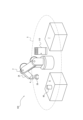
- a robot control system 100 includes a robot 2, a robot control device 110, a holding mode determination device 10, a display device 20, and a camera 4.
- the robot 2 holds the object 80 to be held by the end effector 2B and performs the work.
- the held object 80 is also simply referred to as an object.
- a robot controller 110 controls the robot 2 .
- the holding manner determination device 10 determines the manner in which the robot 2 holds the object to be held 80 and outputs the determination to the robot control device 110 .
- a manner in which the robot 2 holds the object to be held 80 is also simply referred to as a holding manner.
- the holding mode includes the position at which the robot 2 contacts the object 80 to be held, the force the robot 2 applies to the object 80 to be held, and the like.
- the robot 2 holds the holding object 80 at the work start point 6 . That is, the robot control device 110 controls the robot 2 to hold the object 80 to be held at the work start point 6 .
- the robot 2 may move the holding object 80 from the work start point 6 to the work target point 7 .
- the holding target 80 is also called a work target.
- the robot 2 operates inside the operating range 5 .
- the robot 2 has an arm 2A and an end effector 2B.
- the arm 2A may be configured as, for example, a 6-axis or 7-axis vertical articulated robot.
- the arm 2A may be configured as a 3-axis or 4-axis horizontal articulated robot or SCARA robot.
- the arm 2A may be configured as a 2-axis or 3-axis Cartesian robot.
- Arm 2A may be configured as a parallel link robot or the like.
- the number of shafts forming the arm 2A is not limited to the illustrated one.
- the robot 2 has an arm 2A connected by a plurality of joints and operates by driving the joints.
- the end effector 2B may include, for example, a gripping hand configured to grip the object 80 to be held.
- the grasping hand may have multiple fingers. The number of fingers of the grasping hand may be two or more. The fingers of the grasping hand may have one or more joints.
- the end effector 2B may include a suction hand that is configured to suction and hold the object 80 to be held.
- the end effector 2B may include a scooping hand configured to scoop and hold the object 80 to be held.
- the end effector 2B is also called a holding section that holds the object 80 to be held.
- the end effector 2B is not limited to these examples, and may be configured to perform various other operations. In the configuration illustrated in FIG. 1, the end effector 2B is assumed to include a grasping hand.
- the robot 2 can control the position of the end effector 2B by operating the arm 2A.
- the end effector 2B may have an axis that serves as a reference for the direction in which it acts on the object to be held 80 .
- the robot 2 can control the direction of the axis of the end effector 2B by operating the arm 2A.
- the robot 2 controls the start and end of the action of the end effector 2B acting on the object 80 to be held.
- the robot 2 can move or process the holding object 80 by controlling the position of the end effector 2B or the direction of the axis of the end effector 2B and controlling the operation of the end effector 2B. In the configuration illustrated in FIG.
- the robot 2 causes the end effector 2B to hold the holding object 80 at the work start point 6 and moves the end effector 2B to the work target point 7 .
- the robot 2 causes the end effector 2B to release the held object 80 at the work target point 7 . By doing so, the robot 2 can move the object 80 to be held from the work start point 6 to the work target point 7 .
- the robot control system 100 further comprises sensors.
- the sensor detects physical information of the robot 2 .
- the physical information of the robot 2 may include information on the actual position or orientation of each constituent part of the robot 2 or the velocity or acceleration of each constituent part of the robot 2 .
- the physical information of the robot 2 may include information about forces acting on each component of the robot 2 .
- the physical information of the robot 2 may include information about the current flowing through the motors that drive each component of the robot 2 or the torque of the motors.
- the physical information of the robot 2 represents the result of the actual motion of the robot 2 . In other words, the robot control system 100 can grasp the result of the actual motion of the robot 2 by acquiring the physical information of the robot 2 .
- the sensor may include a force sensor or a tactile sensor that detects force acting on the robot 2, distributed pressure, slippage, or the like as the physical information of the robot 2.
- the sensor may include a motion sensor that detects the position or posture of the robot 2 or the speed or acceleration as the physical information of the robot 2 .
- the sensor may include a current sensor that detects the current flowing through the motor that drives the robot 2 as the physical information of the robot 2 .
- the sensor may include a torque sensor that detects the torque of the motor that drives the robot 2 as the physical information of the robot 2 .
- the sensor may be installed in the joint of the robot 2 or in the joint driving section that drives the joint.
- the sensor may be installed on the arm 2A of the robot 2 or the end effector 2B.
- the sensor outputs the detected physical information of the robot 2 to the robot control device 110 .
- the sensor detects and outputs physical information of the robot 2 at a predetermined timing.
- the sensor outputs physical information of the robot 2 as time-series data.
- the robot control system 100 is assumed to have a camera 4 attached to the end effector 2B of the robot 2 .
- the camera 4 shoots the held object 80 from the end effector 2B toward the held object 80, for example. That is, the camera 4 photographs the held object 80 from the direction in which the end effector 2B holds the held object 80 .
- An image of the held object 80 photographed from the direction in which the end effector 2B holds the held object 80 is also referred to as a held target image.
- the camera 4 may also include a depth sensor and be configured to be able to acquire depth data of the held object 80 . Note that the depth data is data regarding the distance in each direction within the angle of view range of the depth sensor.
- the depth data can also be said to be information about the distance from the camera 4 to the measurement point.
- An image captured by the camera 4 may include monochrome luminance information, or may include luminance information of each color represented by RGB (Red, Green and Blue) or the like.
- RGB Red, Green and Blue
- the number of cameras 4 is not limited to one, and may be two or more.
- the camera 4 is not limited to being attached to the end effector 2B, and may be provided at any position where the held object 80 can be photographed.
- the image to be held may be combined based on the image captured by the camera 4 attached to the structure.
- the image to be held may be synthesized by image conversion based on the relative position and orientation of the end effector 2B with respect to the mounting position and orientation of the camera 4 .
- images to be retained may be capable of being generated from CAD and drawing data.
- the holding state determining device 10 includes a control section 12 and an interface (I/F) 14 .
- the interface 14 acquires information or data relating to the object to be held 80 or the like from an external device and outputs information or data to the external device. Also, the interface 14 acquires an image of the held object 80 captured by the camera 4 .
- the interface 14 outputs information or data to the display device 20 and causes a control section of the display device 20 to be described later to display the information or data.
- the control unit 12 determines how the robot 2 holds the object 8 based on the information or data acquired by the interface 14 , and outputs the decision to the robot control device 110 via the interface 14 .
- the control unit 12 may include at least one processor to provide control and processing power to perform various functions.
- the processor may execute programs that implement various functions of the controller 12 .
- a processor may be implemented as a single integrated circuit.
- An integrated circuit is also called an IC (Integrated Circuit).
- a processor may be implemented as a plurality of communicatively coupled integrated and discrete circuits. Processors may be implemented based on various other known technologies.
- the control unit 12 may include a storage unit.
- the storage unit may include an electromagnetic storage medium such as a magnetic disk, or may include a memory such as a semiconductor memory or a magnetic memory.
- the storage unit stores various information.
- the storage unit stores programs and the like executed by the control unit 12 .
- the storage unit may be configured as a non-transitory readable medium.
- the storage section may function as a work memory for the control section 12 . At least part of the storage unit may be configured separately from the control unit 12 .
- the interface 14 may be configured including a communication device configured to be capable of wired or wireless communication.
- a communication device may be configured to be able to communicate with communication schemes based on various communication standards.
- a communication device may be configured according to known communication technologies.
- the interface 14 may include an input device that receives input of information, data, etc. from the user.
- the input device may include, for example, a touch panel or touch sensor, or a pointing device such as a mouse.
- the input device may be configured including physical keys.
- the input device may include an audio input device such as a microphone.
- the interface 14 may be configured to be connectable to an external input device.
- the interface 14 may be configured to acquire information input to an external input device from the external input device.
- the interface 14 may include an output device that outputs information or data to the user.
- the output device may include, for example, an audio output device such as a speaker that outputs auditory information such as sound.
- the output device may include a vibrating device that vibrates to provide tactile information to the user.
- Output devices are not limited to these examples, and may include other various devices.
- the interface 14 may be configured to be connectable to an external output device. Interface 14 may output information to an external output device, much like an external output device outputs information to a user.
- the interface 14 may be configured to be connectable to a display device 20, which will be described later, as an external output device.
- the display device 20 displays information, data, or the like to the user.
- the display device 20 may include a control section that controls display.
- the display device 20 may include, for example, an LCD (Liquid Crystal Display), an organic EL (Electro-Luminescence) display or an inorganic EL display, or a PDP (Plasma Display Panel).
- the display device 20 is not limited to these displays, and may be configured to include other various types of displays.
- the display device 20 may include a light emitting device such as an LED (Light Emission Diode) or an LD (Laser Diode).
- the display device 20 may be configured including other various devices.
- the display device 20 may also include an input device that accepts input of information, data, or the like from the user.
- the input device may include, for example, a touch panel or touch sensor, or a pointing device such as a mouse.
- the input device may be configured including physical keys.
- the input device may include an audio input device such as a microphone.
- An input device may be connected to the interface 14, for example.
- the robot control device 110 acquires information specifying the holding mode from the holding mode determining device 10, and controls the robot 2 so that the robot 2 holds the held object 80 in the holding mode determined by the holding mode determining device 10. .
- the robot controller 110 may be configured with at least one processor to provide control and processing power to perform various functions.
- Each component of the robot control device 110 may be configured including at least one processor.
- a plurality of components among the components of the robot control device 110 may be realized by one processor.
- the entire robot controller 110 may be implemented with one processor.
- the processor may execute programs that implement various functions of the robot controller 110 .
- the processor may be configured identically or similarly to the processor used in the retention state determination device 10 .
- the robot control device 110 may include a storage unit.
- the storage unit may be configured identically or similarly to the storage unit used in the holding state determination device 10 .
- the robot control device 110 may include the holding mode determination device 10 .
- the robot control device 110 and the holding mode determination device 10 may be configured separately.
- the control unit 12 of the holding mode determination device 10 determines the holding mode of the holding object 80 based on the learned model.
- the learned model is configured to receive as an input an image of the object 80 to be held, and to output an estimation result of the holding mode of the object 80 to be held.
- the control unit 12 generates a trained model.
- the control unit 12 acquires an image of the held object 80 from the camera 4, inputs the image into the learned model, and acquires an estimation result of the holding state of the held object 80 from the learned model.
- the control unit 12 determines the holding mode based on the estimation result of the holding mode of the holding object 80 and outputs the holding mode to the robot control device 110 .
- the robot control device 110 controls the robot 2 to hold the object 80 in the holding manner acquired from the holding manner determination device 10 .
- the control unit 12 learns a photographed image of the holding object 80 or an image generated from CAD data or the like of the holding object 80 as learning data, and prepares a learned model for estimating the holding state of the holding object 80. Generate.
- the learning data may include teacher data used in so-called supervised learning.
- the learning data may include data generated by the device itself that performs learning, which is used in so-called unsupervised learning.
- An image obtained by capturing the holding object 80 or an image generated as an image of the holding object 80 is collectively referred to as an object image.
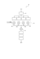
- the inference model includes a class inference model 40 and a holding mode inference model 50 .
- the control unit 12 updates the learning model by learning using the object image as learning data, and generates a learned model.
- the class inference model 40 accepts an object image as an input.
- the class inference model 40 estimates the holding section into which the holding object 80 should be classified based on the input object image. That is, the class inference model 40 classifies the object into one of a plurality of possible holding categories.
- a plurality of holding partitions that can be inferred by class inference model 40 are partitions that can be output by class inference model 40 .
- a holding section is a section representing a difference in shape of the holding object 80, and is also called a class.
- the class inference model 40 classifies the input target image into a predetermined class.
- the class inference model 40 outputs a classification result of classifying the held object 80 into a predetermined class based on the object image. In other words, the class inference model 40 estimates the class to which the held object 80 belongs when the held object 80 is classified into classes.
- the class inference model 40 outputs class inference results as class information.
- a class that can be inferred by class inference model 40 may be determined based on the shape of held object 80 .
- a class that can be estimated by the class inference model 40 may be determined based on various characteristics of the object 80 to be held, such as surface condition, material, hardness, and the like.
- it is assumed that the number of classes that can be estimated by the class inference model 40 is four.
- the four classes are referred to as the first class, second class, third class and fourth class respectively.
- the number of classes may be three or less or five or more.
- the holding mode inference model 50 receives the object image and the class information output from the class inference model 40 as inputs.
- the holding mode inference model 50 estimates the holding mode of the held object 80 based on the input object image and class information, and outputs the holding mode estimation result.
- the class inference model 40 and the retention mode inference model 50 are each configured, for example, as a CNN (Convolution Neural Network) having multiple layers.
- the layers of class inference model 40 are represented as processing layers 42 .
- the layers of the retention mode inference model 50 are represented as processing layers 52 .
- Information input to the class inference model 40 and the retention mode inference model 50 is subjected to convolution processing based on predetermined weighting factors in each layer of the CNN. In training the class inference model 40 and the retention mode inference model 50, the weighting factors are updated.
- Class inference model 40 and retention mode inference model 50 may be configured by VGG 16 or ResNet 50 .
- the class inference model 40 and the holding mode inference model 50 are not limited to these examples, and may be configured as various other models.
- the holding mode inference model 50 includes a multiplier 54 that receives input of class information. When the number of classes is four, the holding mode inference model 50, as shown in FIG. branch.
- the multiplier 54 includes a first multiplier 541, a second multiplier 542, a third multiplier 543 and a fourth multiplier 544 corresponding to each of the four classes.
- a first multiplier 541, a second multiplier 542, a third multiplier 543, and a fourth multiplier 544 multiply the output of the processing layer 52 corresponding to each of the four classes by weighting coefficients.
- the hold-mode inference model 50 includes an adder 56 that adds the outputs of the first multiplier 541 , the second multiplier 542 , the third multiplier 543 and the fourth multiplier 544 .
- the output of adder 56 is input to processing layer 52 .
- the retention mode inference model 50 outputs the output of the processing layer 52 located after the adder 56 as the estimation result of the retention mode.
- the weighting coefficients by which the output of the processing layer 52 is multiplied by the first multiplier 541, the second multiplier 542, the third multiplier 543, and the fourth multiplier 544 are based on the class information input to the multiplier 54. determined by The class information indicates which of the four classes the holding object 80 is classified into. When the holding object 80 is classified into the first class, the weighting coefficient of the first multiplier 541 is 1, and the weighting coefficients of the second multiplier 542, the third multiplier 543 and the fourth multiplier 544 are becomes 0. In this case, the output of processing layer 52 corresponding to the first class is output from adder 56 .
- the class information may be expressed as the probability that the holding object 80 is classified into each of the four classes.
- the probabilities that the holding object 80 is classified into the first, second, third and fourth classes may be represented by X1, X2, X3 and X4.
- the adder 56 outputs the output obtained by multiplying the output of the processing layer 52 corresponding to the first class by X1, the output obtained by multiplying the output of the processing layer 52 corresponding to the second class by X2, and the output of the third class.
- the output obtained by multiplying the output of the corresponding processing layer 52 by X3 and the output obtained by multiplying the output of the processing layer 52 corresponding to the fourth class by X4 are added and output.
- the control unit 12 generates a class inference model 40 and a holding mode inference model 50 as learned models by learning the object image as learning data.
- the control unit 12 needs correct data in order to generate a trained model.
- the control unit 12 requires learning data associated with information indicating to which class an image used as learning data should be correctly classified.
- the control unit 12 needs learning data associated with information representing a position that is correct as the gripping position of the object shown in the image used as the learning data.
- the trained model used in the robot control system 1 may include a model that has learned the class or gripping position regarding the object of the object image during learning, or has learned the class or gripping position. may include models that are not Even if the trained model has not learned the class or gripping position, the control unit 12 estimates the class and gripping position of the target object with reference to the class and gripping position of the learned object similar to the target object. may Therefore, in the robot control system 1 according to this embodiment, the control unit 12 may learn the target object itself or may not learn the target object itself in order to generate a trained model.
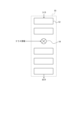
- the control unit 12 configures the learned model so that the class information from the class inference model 40 is input to the holding mode inference model 50 via the conversion unit 60 .
- the trained model includes the conversion unit 60 positioned between the class inference model 40 and the holding mode inference model 50 .
- the control unit 12 inputs an object image to the class inference model 40 and causes the class inference model 40 to output class information.
- the control unit 12 inputs the object image to the holding mode inference model 50, inputs the class information from the class inference model 40 to the holding mode inference model 50 via the conversion unit 60, and holds it in the holding mode inference model 50.
- the estimation result of the holding mode of the object 80 is output.
- the class information output from the class inference model 40 indicates which of the first to fourth classes the held object 80 contained in the input object image is classified into.
- the class inference model 40 is configured to output "1000" as the class information when estimating the holding division (class) into which the holding object 80 is to be classified as the first class.
- the class inference model 40 is configured to output "0100” as class information when estimating the holding section (class) into which the holding object 80 is to be classified as the second class.
- the class inference model 40 is configured to output "0010" as class information when estimating that the holding division (class) into which the holding object 80 is to be classified is the third class.
- the class inference model 40 is configured to output "0001" as class information when estimating the holding section (class) into which the holding object 80 is to be classified as the fourth class.
- the conversion unit 60 converts the class information from the class inference model 40 and inputs it to the multiplier 54 of the retention mode inference model 50 .
- the conversion unit 60 converts it to another character string such as "0100", and transfers the converted class information to the holding mode inference model 50.
- the conversion unit 60 may be configured to output the class information “1000” input from the class inference model 40 to the holding mode inference model 50 as it is.
- the conversion unit 60 may have a table specifying rules for converting class information, and may be configured to convert the class information based on the table.
- the conversion unit 60 may be configured to convert the class information with a matrix, a formula, or the like.
- control unit 12 may apply only the holding mode inference model 50 as the learned model and directly input the class information to the holding mode inference model 50.
- a shape image 81 representing the shape of a held object 80 illustrated in FIGS. 7A, 7B, and 7C is input to the learned model as the object image.
- the objects 80 included in the shape image 81 are classified into classes based on the shape of the objects 80 to be held.
- the shape of the object to be held 80 is an O-shape
- the object to be held 80 included in the shape image 81 is classified into the first class.
- the shape of the object to be held 80 is I-shaped
- the object to be held 80 included in the shape image 81 is classified into the second class.
- the shape of the object to be held 80 is J-shaped
- the object to be held 80 included in the shape image 81 is classified into the third class. It can also be said that the J-shape is a combination of the I-shape and the O-shape.
- the holding object 80 has another shape, the holding object 80 included in the shape image 81 is classified into the fourth class.
- the class inference model 40 outputs "1000" as class information when it is estimated that the holding object 80 included in the shape image 81 is classified into the first class.
- the holding position 82 is estimated inside the O-shaped holding object 80 in the shape image 81 .
- the class inference model 40 outputs "0100” as class information when it is estimated that the held object 80 included in the shape image 81 is classified into the second class.
- the holding mode inference model 50 acquires “0100” as the class information, it estimates the positions on both sides near the center of the I-shape in the shape image 81 as the holding positions 82 .
- the class inference model 40 outputs "0010" as class information when it is estimated that the held object 80 included in the shape image 81 is classified into the third class.
- the holding mode inference model 50 estimates the holding position 82 of the holding object 80 included in the shape image 81 according to the class into which the holding object 80 included in the shape image 81 is classified. For example, when the holding mode inference model 50 acquires “0010” as the class information, it estimates the positions on both sides near the end of the J shape in the shape image 81 as the holding positions 82 . In other words, the holding mode inference model 50 estimates the positions on both sides near the far end of the I shape from the O shape as the holding positions 82 in the combination of the I shape and the O shape.
- the control unit 12 can set rules for converting class information in the conversion unit 60 .
- the control unit 12 receives user input through the interface 14 and sets rules based on the user input.
- the control unit 12 inputs an object image to the learned model, and outputs holding modes estimated when the object to be held 80 is classified into each of a plurality of classes from the learned model. Specifically, as shown in FIGS. 8A, 8B, and 8C, the control unit 12 inputs an image in which a screw is a holding object 80 as an object image to the learned model.
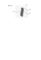
- the screw has a screw head 83 and a screw shaft 84 . If the screw as the object to be held 80 included in the shape image 81 of the screw is temporarily classified into the first class, the trained model cannot identify the position corresponding to the inside of the screw and cannot estimate the holding position 82 . Therefore, the holding position 82 is not displayed in the shape image 81 including screws classified into the first class.
- the learned model estimates both sides of the screw shaft 84 near the center as holding positions 82 . If the screw as the object to be held 80 included in the shape image 81 of the screw is temporarily classified into the third class, the trained model sets positions on both sides near the end of the screw shaft 84 farther from the screw head 83 as holding positions. Estimated as 82.
- the control unit 12 presents the result of estimating the holding position 82 in the shape image 81 to the user when the learned model classifies the holding object 80 included in the shape image 81 into each class. Specifically, the control unit 12 displays an image in which the holding position 82 is superimposed on the shape image 81 illustrated in FIGS. 8A, 8B, and 8C. By displaying it on the display device 20 as a candidate for 82, the user is allowed to visually recognize the image. The user confirms the holding positions 82 (candidates for the holding positions 82) when the holding object 80 included in the shape image 81 is classified into each class, and determines which holding position the screw as the holding object 80 should be held. It can be determined whether position 82 is suitable.
- the control unit 12 allows the user to input, through the I/F 14 , information specifying which holding position 82 the user has determined to be suitable among the candidates for the holding position 82 . Based on the user's input to the I/F 14, the control unit 12 acquires the class corresponding to the holding position 82 judged to be suitable by the user.
- the control unit 12 causes the holding mode inference model 50 to estimate the holding position 82 of the class that the user has determined to be suitable. Specifically, the control unit 12 can control the holding position 82 to be estimated by the holding manner inference model 50 by controlling the class information input to the holding manner inference model 50 .
- the control unit 12 determines that the object to be held 80 is classified into the third class.
- the holding mode inference model 50 can be caused to estimate the holding position 82 as an estimation result.
- the control unit 12 inputs “0010” indicating the third class to the holding mode inference model 50 as class information to which the held object 80 belongs.
- the control unit 12 inputs "0010" as the class information to the holding mode inference model 50 even if the class information output by the class inference model 40 is originally "0100" indicating the second class.
- the holding mode of the holding object 80 classified into the second class is presumed to be the holding mode corresponding to the second class.
- the holding mode inference model 50 is caused to estimate the holding mode.
- the control unit 12 causes the conversion unit 60 to input "0010" as the class information to the holding mode inference model 50.
- the control unit 12 can convert the class into which the object to be held 80 is classified into another class, and cause the holding mode inference model 50 to make an estimation so as to output it as an estimation result. For example, even when the holding object 80 is classified into the second class, the control unit 12 outputs the holding position 82 as the estimation result assuming that the holding object 80 is classified into the third class. , may be estimated by the retention mode inference model 50 . The control unit 12 performs the The holding state inference model 50 may be made to estimate.
- the control unit 12 converts it to "0010” and inputs it to the holding mode inference model 50, so that the class information from the class inference model 40 is " 0010” is converted into “0100” and input to the holding mode inference model 50, the conversion rule in the conversion unit 60 is set.
- the control unit 12 by configuring the control unit 12 so that the conversion rule can be set, for example, when processing a plurality of objects in succession, the user can select a holding mode each time. can be reduced.
- the conversion rule may be set such that, once the holding mode is determined by the user, the holding modes of the plurality of objects become the determined holding mode.
- a class without a retention mode may be set as a retention division.
- the retention mode inference model 50 may estimate that there is no retention mode when a certain class is input.
- the control unit 12 may determine that an object classified into a class other than the class assumed by the user among the plurality of objects is a foreign object. good. Then, the control unit 12 can perform control so as not to hold the foreign object by converting the class of the object determined to be a foreign object into a class having no holding mode according to the set conversion rule. .
- the control unit 12 of the holding state determination device 10 may execute the holding state determination method including the procedure of the flowchart illustrated in FIG. 9 .
- the holding mode determination method may be implemented as a holding mode determination program that is executed by a processor that configures the control unit 12 .
- the retention mode determination program may be stored in a non-transitory computer-readable medium.
- the control unit 12 inputs the target object image to the learned model (step S1).
- the control unit 12 classifies the held object 80 included in the object image into classes by the class inference model 40 (step S2). Specifically, the class inference model 40 estimates the class into which the object to be held 80 is classified, and outputs the estimation result as class information.
- the control unit 12 estimates the holding mode when the holding object 80 is assumed to be the class (for example, the third class) estimated by the class inference model 40 or another class (for example, the first, second, and fourth classes). Then, the estimation result is generated as a holding mode candidate and displayed on the display device 20 (step S3). Specifically, the control unit 12 displays an image in which the holding position 82 is superimposed on the object image. At this time, the class estimated by the class inference model 40 may be displayed in an identifiable manner.
- the control unit 12 allows the user to select a holding mode from candidates (step S4). Specifically, the control unit 12 causes the user to input which holding mode to select from the holding mode candidates through the I/F 14, and acquires information specifying the holding mode selected by the user. In other words, if the user considers that the holding mode in the class estimated by the class inference model 40 is not appropriate for the holding object 80, he or she selects another holding mode.
- the control unit 12 causes the learned model to estimate the holding mode so that the held object 80 is held in the holding mode selected by the user, and outputs the estimated holding mode to the robot control device 110 (step S5). After executing the procedure of step S5, the control unit 12 ends the execution of the procedure of the flowchart of FIG.
- the holding mode determination device 10 allows the user to select the holding mode estimated by the learned model, and can control the robot 2 in the holding mode selected by the user. By doing so, the user can control the holding mode by the robot 2 even if the holding mode estimation result by the learned model cannot be controlled. As a result, the convenience of the trained model that outputs the holding mode of the holding object 80 is improved.
- the holding mode determination device 10 determines the holding position 82 as the holding mode.
- the holding manner determination device 10 can determine other manners in addition to the holding position 82 as the holding manner.
- the holding mode determination device 10 may determine, for example, the force applied by the robot 2 to hold the held object 80 as the holding mode.
- the holding mode inference model 50 estimates and outputs the force applied to hold the holding object 80 .
- the holding mode determination device 10 may determine, for example, the type of hand with which the robot 2 holds the held object 80 as the holding mode.
- the holding state inference model 50 estimates and outputs the type of hand used to hold the holding object 80 .
- the holding manner determination device 10 may cause the display device 20 to display the holding manner estimated by the holding manner inference model 50 by superimposing it on the object image.
- the holding mode determination device 10 may display the position where the held object 80 is held by the fingers as the holding position 82 . Further, the holding mode determination device 10 may cause the display device 20 to display positions within a predetermined range from the position where the held object 80 is held.
- a storage medium in which the program is recorded (For example, an optical disk, a magneto-optical disk, a CD-ROM, a CD-R, a CD-RW, a magnetic tape, a hard disk, or a memory card) can be used.
- the implementation form of the program is not limited to an application program such as an object code compiled by a compiler or a program code executed by an interpreter. good.
- the program may or may not be configured so that all processing is performed only in the CPU on the control board.
- the program may be configured to be partially or wholly executed by another processing unit mounted on an expansion board or expansion unit added to the board as required.
- Embodiments according to the present disclosure are not limited to any specific configuration of the embodiments described above. Embodiments of the present disclosure extend to any novel feature or combination thereof described in the present disclosure or any novel method or process step or combination thereof described. be able to.
- Descriptions such as “first” and “second” in this disclosure are identifiers for distinguishing the configurations. Configurations that are differentiated in descriptions such as “first” and “second” in this disclosure may interchange the numbers in that configuration. For example, a first class can exchange identifiers “first” and “second” with a second class. The exchange of identifiers is done simultaneously. The configurations are still distinct after the exchange of identifiers. Identifiers may be deleted. Configurations from which identifiers have been deleted are distinguished by codes. The description of identifiers such as “first” and “second” in this disclosure should not be used as a basis for interpreting the order of the configuration or the existence of lower numbered identifiers.
- holding mode determination device (12: control unit, 14: interface)
- display device 40 class inference model (42: processing layer)
- retention mode inference model 52: processing layer
- conversion unit 80 object to be held (83: screw head, 84: screw shaft)
- shape image 82 holding position
- robot control system (2: robot, 2A: arm, 2B: end effector, 3: sensor, 4: camera, 5: range of influence of robot, 6: work start point, 7: work target point , 110: robot controller)
Landscapes
- Engineering & Computer Science (AREA)
- Robotics (AREA)
- Mechanical Engineering (AREA)
- Human Computer Interaction (AREA)
- Image Analysis (AREA)
- Manipulator (AREA)
Abstract
Description
図1に示されるように、本開示の一実施形態に係るロボット制御システム100は、ロボット2と、ロボット制御装置110と、保持態様決定装置10と、表示装置20と、カメラ4とを備える。ロボット2は、保持対象物80をエンドエフェクタ2Bによって保持して作業を実行する。保持対象物80は、単に対象物とも称される。ロボット制御装置110は、ロボット2を制御する。保持態様決定装置10は、ロボット2が保持対象物80を保持するときの態様を決定し、ロボット制御装置110に出力する。ロボット2に保持対象物80を保持させる態様は、単に保持態様とも称される。保持態様は、ロボット2が保持対象物80に接触する位置又はロボット2が保持対象物80に加える力等を含む。 (Configuration example of robot control system 100)
As shown in FIG. 1 , a
ロボット2は、アーム2Aと、エンドエフェクタ2Bとを備える。アーム2Aは、例えば、6軸又は7軸の垂直多関節ロボットとして構成されてよい。アーム2Aは、3軸又は4軸の水平多関節ロボット又はスカラロボットとして構成されてもよい。アーム2Aは、2軸又は3軸の直交ロボットとして構成されてもよい。アーム2Aは、パラレルリンクロボット等として構成されてもよい。アーム2Aを構成する軸の数は、例示したものに限られない。言い換えれば、ロボット2は、複数の関節で接続されるアーム2Aを有し、関節の駆動によって動作する。 <
The
ロボット制御システム100は、更にセンサを備える。センサは、ロボット2の物理情報を検出する。ロボット2の物理情報は、ロボット2の各構成部の現実の位置若しくは姿勢、又は、ロボット2の各構成部の速度若しくは加速度に関する情報を含んでよい。ロボット2の物理情報は、ロボット2の各構成部に作用する力に関する情報を含んでよい。ロボット2の物理情報は、ロボット2の各構成部を駆動するモータに流れる電流又はモータのトルクに関する情報を含んでよい。ロボット2の物理情報は、ロボット2の実際の動作の結果を表す。つまり、ロボット制御システム100は、ロボット2の物理情報を取得することによって、ロボット2の実際の動作の結果を把握することができる。 <Sensor>
The
図1に示される構成例において、ロボット制御システム100は、ロボット2のエンドエフェクタ2Bに取り付けられたカメラ4を備えるとする。カメラ4は、例えば、エンドエフェクタ2Bから保持対象物80に向かって保持対象物80を撮影する。つまり、カメラ4は、エンドエフェクタ2Bが保持対象物80を保持する方向から保持対象物80を撮影する。エンドエフェクタ2Bが保持対象物80を保持する方向から保持対象物80を撮影した画像は、保持対象画像とも称される。また、カメラ4は、デプスセンサを備え、保持対象物80のデプスデータを取得可能に構成されてもよい。なお、デプスデータとは、デプスセンサの画角範囲内の方向別の距離に関するデータである。より具体的には、デプスデータは、カメラ4から測定点までの距離に関する情報ともいえる。カメラ4が撮影する画像は、モノクロの輝度情報を含んでもよいし、RGB(Red, Green and Blue)等で表される各色の輝度情報を含んでもよい。カメラ4の数は、1つに限られず、2つ以上であってもよい。 <Camera 4>
In the configuration example shown in FIG. 1 , the
図1に示されるように、保持態様決定装置10は、制御部12と、インタフェース(I/F)14とを備える。インタフェース14は、外部装置から保持対象物80等に関する情報又はデータを取得したり外部装置に情報又はデータを出力したりする。また、インタフェース14は、カメラ4から保持対象物80を撮影した画像を取得する。インタフェース14は、表示装置20に情報又はデータを出力し、後述する表示装置20の制御部に情報又はデータを表示させる。制御部12は、インタフェース14で取得した情報又はデータに基づいてロボット2による保持対象物8の保持態様を決定し、インタフェース14を介してロボット制御装置110に出力する。 <Holding
As shown in FIG. 1 , the holding
表示装置20は、ユーザに対して情報又はデータ等を表示する。表示装置20は、表示を制御する制御部を備えてよい。表示装置20は、例えば、LCD(Liquid Crystal Display)、有機EL(Electro-Luminescence)ディスプレイ若しくは無機ELディスプレイ、又は、PDP(Plasma Display Panel)等を含んで構成されてよい。表示装置20は、これらのディスプレイに限られず、他の種々の方式のディスプレイを含んで構成されてよい。表示装置20は、LED(Light Emission Diode)又はLD(Laser Diode)等の発光デバイスを含んで構成されてよい。表示装置20は、他の種々のデバイスを含んで構成されてよい。 <
The
ロボット制御装置110は、保持態様決定装置10から保持態様を特定する情報を取得し、保持態様決定装置10で決定した保持態様でロボット2が保持対象物80を保持するようにロボット2を制御する。 <
The
保持態様決定装置10の制御部12は、学習済みモデルに基づいて保持対象物80の保持態様を決定する。学習済みモデルは、保持対象物80を撮影した画像を入力として受け付け、その保持対象物80の保持態様の推定結果を出力するように構成される。制御部12は、学習済みモデルを生成する。制御部12は、保持対象物80を撮影した画像をカメラ4から取得して、その画像を学習済みモデルに入力し、学習済みモデルから保持対象物80の保持態様の推定結果を取得する。制御部12は、保持対象物80の保持態様の推定結果に基づいて保持態様を決定し、ロボット制御装置110に出力する。ロボット制御装置110は、保持態様決定装置10から取得した保持態様でロボット2に保持対象物80を保持させるようにロボット2を制御する。 (Example of operation of holding state determination device 10)
The
制御部12は、保持対象物80を撮影した画像、又は、保持対象物80のCADデータ等から生成した画像を学習用データとして学習し、保持対象物80の保持態様を推定する学習済みモデルを生成する。学習用データは、いわゆる教師あり学習で用いる教師データを含んでよい。学習用データは、いわゆる教師なし学習で用いる、学習を実行する装置自身で生成するデータを含んでよい。保持対象物80を撮影した画像、又は、保持対象物80の画像として生成した画像は、対象物画像と総称される。図3に示されるように、推論モデルは、クラス推論モデル40と、保持態様推論モデル50とを含む。制御部12は、対象物画像を学習用データとする学習によって学習中のモデルを更新し、学習済みモデルを生成する。 <Generation of trained model>
The
制御部12は、図5に示されるように、クラス推論モデル40からのクラス情報が変換部60を介して保持態様推論モデル50に入力されるように学習済みモデルを構成する。つまり、学習済みモデルは、クラス推論モデル40と保持態様推論モデル50との間に位置する変換部60を含む。制御部12は、クラス推論モデル40に対象物画像を入力し、クラス推論モデル40にクラス情報を出力させる。制御部12は、保持態様推論モデル50に対象物画像を入力し、かつ、クラス推論モデル40から変換部60を介してクラス情報を保持態様推論モデル50に入力し、保持態様推論モデル50に保持対象物80の保持態様の推定結果を出力させる。 <Estimation of retention mode by trained model>
As shown in FIG. 5 , the
制御部12は、変換部60においてクラス情報を変換するルールを設定できる。制御部12は、インタフェース14によってユーザの入力を受け付け、ユーザの入力に基づいてルールを設定する。 <Setting of Conversion Rule of
The
The
保持態様決定装置10の制御部12は、図9に例示されるフローチャートの手順を含む保持態様決定方法を実行してもよい。保持態様決定方法は、制御部12を構成するプロセッサに実行させる保持態様決定プログラムとして実現されてもよい。保持態様決定プログラムは、非一時的なコンピュータ読み取り可能な媒体に格納されてよい。 <Procedure example of retention mode determination method>
The
以上述べてきたように、本実施形態に係る保持態様決定装置10は、学習済みモデルが推定した保持態様をユーザに選択させ、ユーザが選択した保持態様でロボット2を制御できる。このようにすることで、ユーザは、学習済みモデルによる保持態様の推定結果を制御できなくても、ロボット2による保持態様を制御できる。その結果、保持対象物80の保持態様を出力する学習済みモデルの利便性が向上する。 <Summary>
As described above, the holding
以下、他の実施形態が説明される。 (Other embodiments)
Other embodiments are described below.
20 表示装置
40 クラス推論モデル(42:処理層)
50 保持態様推論モデル(52:処理層、54:乗算器(541~544:第1~第4乗算器)、56:加算器)
60 変換部
80 保持対象物(83:ネジ頭、84:ネジ軸)
81 形状画像
82 保持位置
100 ロボット制御システム(2:ロボット、2A:アーム、2B:エンドエフェクタ、3:センサ、4:カメラ、5:ロボットの影響範囲、6:作業開始地点、7:作業目標地点、110:ロボット制御装置) 10 holding mode determination device (12: control unit, 14: interface)
20
50 retention mode inference model (52: processing layer, 54: multiplier (541 to 544: first to fourth multipliers), 56: adder)
60
81
Claims (14)
- 推定され得る複数の保持区分の少なくとも1つに対象物を分類することによって推定されたロボットの前記対象物の少なくとも1つの保持態様を、前記対象物の画像と共に、表示装置に出力する制御部と、
前記表示装置を介して、前記少なくとも1つの保持態様に対する、ユーザの選択を取得するインタフェースと
を備えるロボットの保持態様決定装置。 a controller for outputting at least one holding mode of the object of the robot estimated by classifying the object into at least one of a plurality of holding categories that can be estimated, together with an image of the object, to a display device; ,
an interface for obtaining a user's selection of said at least one holding manner via said display device. - 前記インタフェースは、前記ユーザが選択した前記保持態様を、前記ロボットが前記対象物を前記ユーザが選択した保持態様で保持するように、前記ロボットの動作を制御するロボット制御装置に出力する、請求項1に記載のロボットの保持態様決定装置。 3. The interface outputs the holding mode selected by the user to a robot control device that controls an operation of the robot so that the robot holds the object in the holding mode selected by the user. 2. The robot holding mode determination device according to 1.
- 前記推定され得る複数の保持区分は、前記対象物の画像に基づき、前記対象物を所定のクラスに分類した分類結果を出力するクラス推論モデルにより出力可能な保持区分である、請求項1又は2に記載のロボットの保持態様決定装置。 3. The plurality of presumable holding sections are holding sections that can be output by a class inference model that outputs a classification result of classifying the object into a predetermined class based on the image of the object. 2. The robot holding mode determination device according to 1.
- 前記制御部は、入力される保持区分に基づいて前記対象物の前記保持態様を出力する保持態様推論モデルに対して前記分類結果が入力された場合の、各々の前記分類結果についての前記保持態様を前記表示装置に出力する、請求項3に記載のロボットの保持態様決定装置。 The control unit controls the holding mode of each of the classification results when the classification result is input to a holding mode inference model that outputs the holding mode of the object based on the input holding classification. 4. The robot holding mode determination device according to claim 3, wherein the display device outputs the .
- 前記保持態様推論モデルは、前記ロボットが前記対象物を保持する態様として、前記ロボットが前記対象物を保持する位置を決定する、請求項4に記載のロボットの保持態様決定装置。 5. The holding mode determination device for a robot according to claim 4, wherein the holding mode inference model determines a position at which the robot holds the object as a mode in which the robot holds the object.
- 前記保持態様推論モデルは、前記ロボットが前記対象物を保持する態様として、前記ロボットが前記対象物を保持するために加える力を決定する、請求項4又は5に記載のロボットの保持態様決定装置。 6. The robot holding mode determining apparatus according to claim 4, wherein said holding mode inference model determines a force applied by said robot to hold said object as a mode of holding said object by said robot. .
- 前記保持態様推論モデルは、前記ロボットが前記対象物を保持する態様として、前記ロボットが前記対象物を保持するハンドの種類を決定する、請求項4から6までのいずれか一項に記載のロボットの保持態様決定装置。 7. The robot according to any one of claims 4 to 6, wherein said holding mode inference model determines a type of hand with which said robot holds said object as a mode in which said robot holds said object. holding mode determination device.
- 前記ロボットは、カメラから取得した前記対象物の画像と、前記クラス推論モデル及び前記保持態様推論モデルを含む学習済みモデルの出力とに基づいて、前記対象物を保持する保持部を有し、
前記制御部は、前記ロボットが前記ユーザの選択に対応する前記クラスに基づいて保持態様推論モデルが出力する前記保持態様で前記対象物を保持するように、前記ロボットに前記ユーザの選択を出力する、請求項4から7までのいずれか一項に記載のロボットの保持態様決定装置。 The robot has a holding unit that holds the object based on an image of the object acquired from a camera and an output of a trained model including the class inference model and the holding mode inference model,
The control unit outputs the user's selection to the robot so that the robot holds the object in the holding mode output by the holding mode inference model based on the class corresponding to the user's selection. 8. The holding mode determining device for a robot according to claim 4. - 前記保持部は前記対象物を挟持するための少なくとも2の指を有し、
前記制御部は、前記保持態様として前記指による前記対象物を挟持する位置、又は、前記対象物を挟持する位置から所定範囲内の位置を前記表示装置に出力する、請求項8に記載のロボットの保持態様決定装置。 The holding part has at least two fingers for holding the object,
9. The robot according to claim 8, wherein the control unit outputs to the display device a position where the object is held by the fingers or a position within a predetermined range from the position where the object is held, as the holding mode. holding mode determination device. - 前記制御部は、前記対象物の画像に前記対象物を保持する態様を重畳した画像を前記表示装置に出力する、請求項1から9までのいずれか一項に記載のロボットの保持態様決定装置。 10. The robot holding mode determining apparatus according to claim 1, wherein said control unit outputs to said display device an image in which a mode of holding said object is superimposed on said image of said object. .
- 前記制御部は、推定され得る複数の保持区分の少なくとも1つに対象物を分類するクラス推論モデルから出力される保持区分の分類結果を他の保持区分に変換する変換ルールを設定する、請求項1から10までのいずれか一項に記載のロボットの保持態様決定装置。 3. The control unit sets a conversion rule for converting a classification result of a retention class output from a class inference model that classifies an object into at least one of a plurality of presumable retention classes into another retention class. 11. The robot holding mode determination device according to any one of 1 to 10.
- 前記制御部は、推定され得る複数の保持区分の少なくとも1つに対象物を分類した結果に基づいて、異物を判定する、請求項1から11までのいずれか一項に記載のロボットの保持態様決定装置。 The holding mode of the robot according to any one of claims 1 to 11, wherein the control unit determines a foreign object based on a result of classifying the object into at least one of a plurality of presumable holding categories. decision device.
- 推定され得る複数の保持区分の少なくとも1つに対象物を分類することによって推定されたロボットの前記対象物の少なくとも1つの保持態様を、前記対象物の画像と共に、表示装置に出力することと、
前記表示装置を介して、前記少なくとも1つの保持態様に対する、ユーザの選択を取得することと
を含む、ロボットの保持態様決定方法。 outputting, together with an image of the object, at least one holding mode of the object of the robot estimated by classifying the object into at least one of a plurality of holding categories that can be estimated to a display device;
obtaining a user selection for said at least one holding aspect via said display device. - ロボットと、前記ロボットを制御するロボット制御装置と、前記ロボットが対象物を保持する態様を決定する保持態様決定装置と、表示装置とを備え、
前記保持態様決定装置は、推定され得る複数の保持区分の少なくとも1つに対象物を分類することによって推定されたロボットの前記対象物の少なくとも1つの保持態様を、前記対象物の画像と共に、前記表示装置に出力し、
前記表示装置は、前記対象物の画像と前記対象物の少なくとも1つの保持態様とを表示し、前記少なくとも1つの保持態様に対するユーザの選択の入力を受け付けて前記保持態様決定装置に出力し、
前記保持態様決定装置は、前記表示装置から、前記少なくとも1つの保持態様に対する前記ユーザの選択を取得する、
ロボット制御システム。 A robot, a robot control device that controls the robot, a holding mode determination device that determines a mode in which the robot holds an object, and a display device,
The holding mode determination device determines at least one holding mode of the object of the robot estimated by classifying the object into at least one of a plurality of estimable holding categories together with the image of the object. output to a display device,
The display device displays an image of the object and at least one holding mode of the object, receives an input of a user's selection of the at least one holding mode, and outputs it to the holding mode determination device,
the holding aspect determination device obtains the user's selection for the at least one holding aspect from the display device;
robot control system.
Priority Applications (2)
| Application Number | Priority Date | Filing Date | Title |
|---|---|---|---|
| JP2023542466A JPWO2023022237A1 (en) | 2021-08-19 | 2022-08-19 | |
| CN202280056283.4A CN117813184A (en) | 2021-08-19 | 2022-08-19 | Robot holding form determination device, holding form determination method, and robot control system |
Applications Claiming Priority (2)
| Application Number | Priority Date | Filing Date | Title |
|---|---|---|---|
| JP2021-134391 | 2021-08-19 | ||
| JP2021134391 | 2021-08-19 |
Publications (1)
| Publication Number | Publication Date |
|---|---|
| WO2023022237A1 true WO2023022237A1 (en) | 2023-02-23 |
Family
ID=85239822
Family Applications (1)
| Application Number | Title | Priority Date | Filing Date |
|---|---|---|---|
| PCT/JP2022/031456 WO2023022237A1 (en) | 2021-08-19 | 2022-08-19 | Holding mode determination device for robot, holding mode determination method, and robot control system |
Country Status (3)
| Country | Link |
|---|---|
| JP (1) | JPWO2023022237A1 (en) |
| CN (1) | CN117813184A (en) |
| WO (1) | WO2023022237A1 (en) |
Citations (5)
| Publication number | Priority date | Publication date | Assignee | Title |
|---|---|---|---|---|
| JP2005169564A (en) | 2003-12-11 | 2005-06-30 | Toyota Motor Corp | Method for gripping object of optional shape by robot |
| JP2009214212A (en) * | 2008-03-10 | 2009-09-24 | Toyota Motor Corp | Action teaching system, and action teaching method |
| JP2019010724A (en) * | 2017-06-30 | 2019-01-24 | 大成建設株式会社 | Article arrangement system and food product arrangement system |
| WO2021039850A1 (en) * | 2019-08-26 | 2021-03-04 | 川崎重工業株式会社 | Information processing device, configuration device, image recognition system, robot system, configuration method, learning device, and learned model generation method |
| JP2022038069A (en) * | 2020-08-26 | 2022-03-10 | 川崎重工業株式会社 | Robot system, method for controlling robot, information processing device, computer program, learning device, and method for generating learned model |
-
2022
- 2022-08-19 JP JP2023542466A patent/JPWO2023022237A1/ja active Pending
- 2022-08-19 CN CN202280056283.4A patent/CN117813184A/en active Pending
- 2022-08-19 WO PCT/JP2022/031456 patent/WO2023022237A1/en active Application Filing
Patent Citations (5)
| Publication number | Priority date | Publication date | Assignee | Title |
|---|---|---|---|---|
| JP2005169564A (en) | 2003-12-11 | 2005-06-30 | Toyota Motor Corp | Method for gripping object of optional shape by robot |
| JP2009214212A (en) * | 2008-03-10 | 2009-09-24 | Toyota Motor Corp | Action teaching system, and action teaching method |
| JP2019010724A (en) * | 2017-06-30 | 2019-01-24 | 大成建設株式会社 | Article arrangement system and food product arrangement system |
| WO2021039850A1 (en) * | 2019-08-26 | 2021-03-04 | 川崎重工業株式会社 | Information processing device, configuration device, image recognition system, robot system, configuration method, learning device, and learned model generation method |
| JP2022038069A (en) * | 2020-08-26 | 2022-03-10 | 川崎重工業株式会社 | Robot system, method for controlling robot, information processing device, computer program, learning device, and method for generating learned model |
Also Published As
| Publication number | Publication date |
|---|---|
| CN117813184A (en) | 2024-04-02 |
| JPWO2023022237A1 (en) | 2023-02-23 |
Similar Documents
| Publication | Publication Date | Title |
|---|---|---|
| JP6608890B2 (en) | Machine learning apparatus, robot system, and machine learning method | |
| US9387589B2 (en) | Visual debugging of robotic tasks | |
| US7814037B2 (en) | Information processing apparatus and method, and program for teaching an action to a device in a time-series pattern | |
| WO2020110505A1 (en) | Image generation device, robot training system, image generation method, and image generation program | |
| JP2019084601A (en) | Information processor, gripping system and information processing method | |
| JP2020082322A (en) | Machine learning device, machine learning system, data processing system and machine learning method | |
| WO2020138446A1 (en) | Robot control device, robot system, and robot control method | |
| CN111683799A (en) | Robot motion control device | |
| CN114516060A (en) | Apparatus and method for controlling a robotic device | |
| KR20200059111A (en) | Grasping robot, grasping method and learning method for grasp based on neural network | |
| WO2023022237A1 (en) | Holding mode determination device for robot, holding mode determination method, and robot control system | |
| WO2023027187A1 (en) | Trained model generation method, trained model generation device, trained model, and device for estimating maintenance state | |
| WO2019180916A1 (en) | Robot control device | |
| CN117103277A (en) | Mechanical arm sensing method based on multi-mode data fusion | |
| WO2018012110A1 (en) | Processing device, system, and control method | |
| US20230150142A1 (en) | Device and method for training a machine learning model for generating descriptor images for images of objects | |
| WO2023234062A1 (en) | Data acquisition apparatus, data acquisition method, and data acquisition stand | |
| WO2023234061A1 (en) | Data acquisition device, data acquisition method, and data acquisition stand | |
| JP7271810B2 (en) | Trained model generation device, trained model generation method, and recognition device | |
| JP7482719B2 (en) | ROBOT CONTROL DEVICE, ROBOT CONTROL SYSTEM, AND ROBOT CONTROL METHOD | |
| JP2021016908A (en) | Learning device, robot control system and learning control method | |
| JP7271809B2 (en) | Trained model generation device, trained model generation method, and recognition device | |
| WO2022250152A1 (en) | Hold position determination device and hold position determination method | |
| JP2020082249A (en) | Robot device, robot system, robot control method, and program | |
| CN113226663A (en) | Control device, control method, and program |
Legal Events
| Date | Code | Title | Description |
|---|---|---|---|
| 121 | Ep: the epo has been informed by wipo that ep was designated in this application |
Ref document number: 22858552 Country of ref document: EP Kind code of ref document: A1 |
|
| WWE | Wipo information: entry into national phase |
Ref document number: 2023542466 Country of ref document: JP |
|
| WWE | Wipo information: entry into national phase |
Ref document number: 202280056283.4 Country of ref document: CN |
|
| WWE | Wipo information: entry into national phase |
Ref document number: 2022858552 Country of ref document: EP |
|
| NENP | Non-entry into the national phase |
Ref country code: DE |
|
| ENP | Entry into the national phase |
Ref document number: 2022858552 Country of ref document: EP Effective date: 20240319 |