WO2023017697A1 - Electronic pen - Google Patents
Electronic pen Download PDFInfo
- Publication number
- WO2023017697A1 WO2023017697A1 PCT/JP2022/026901 JP2022026901W WO2023017697A1 WO 2023017697 A1 WO2023017697 A1 WO 2023017697A1 JP 2022026901 W JP2022026901 W JP 2022026901W WO 2023017697 A1 WO2023017697 A1 WO 2023017697A1
- Authority
- WO
- WIPO (PCT)
- Prior art keywords
- electronic pen
- push
- housing
- touch sensor
- attached
- Prior art date
Links
- 230000007246 mechanism Effects 0.000 claims abstract description 23
- 229910052751 metal Inorganic materials 0.000 claims description 19
- 239000002184 metal Substances 0.000 claims description 19
- 238000001514 detection method Methods 0.000 claims description 13
- 101000579646 Penaeus vannamei Penaeidin-1 Proteins 0.000 description 49
- 239000000758 substrate Substances 0.000 description 30
- 238000010586 diagram Methods 0.000 description 10
- 229920005989 resin Polymers 0.000 description 8
- 239000011347 resin Substances 0.000 description 8
- 239000000463 material Substances 0.000 description 5
- 239000007769 metal material Substances 0.000 description 5
- 230000008859 change Effects 0.000 description 4
- 229910000859 α-Fe Inorganic materials 0.000 description 4
- 239000003990 capacitor Substances 0.000 description 3
- 239000012790 adhesive layer Substances 0.000 description 2
- 230000004323 axial length Effects 0.000 description 2
- 229920001971 elastomer Polymers 0.000 description 2
- 239000000806 elastomer Substances 0.000 description 2
- 230000005674 electromagnetic induction Effects 0.000 description 2
- 238000005516 engineering process Methods 0.000 description 2
- 229920006122 polyamide resin Polymers 0.000 description 2
- 229920000139 polyethylene terephthalate Polymers 0.000 description 2
- 239000005020 polyethylene terephthalate Substances 0.000 description 2
- 229920006324 polyoxymethylene Polymers 0.000 description 2
- 229920001875 Ebonite Polymers 0.000 description 1
- 244000043261 Hevea brasiliensis Species 0.000 description 1
- 229930182556 Polyacetal Natural products 0.000 description 1
- 229920000122 acrylonitrile butadiene styrene Polymers 0.000 description 1
- 230000009471 action Effects 0.000 description 1
- 230000000994 depressogenic effect Effects 0.000 description 1
- 230000000694 effects Effects 0.000 description 1
- 230000005484 gravity Effects 0.000 description 1
- 229910001385 heavy metal Inorganic materials 0.000 description 1
- 230000004048 modification Effects 0.000 description 1
- 238000012986 modification Methods 0.000 description 1
- 229920003052 natural elastomer Polymers 0.000 description 1
- 229920001194 natural rubber Polymers 0.000 description 1
- 229920005668 polycarbonate resin Polymers 0.000 description 1
- 239000004431 polycarbonate resin Substances 0.000 description 1
- -1 polyethylene terephthalate Polymers 0.000 description 1
- 230000001105 regulatory effect Effects 0.000 description 1
- 229920003051 synthetic elastomer Polymers 0.000 description 1
- 239000005061 synthetic rubber Substances 0.000 description 1
- 239000002023 wood Substances 0.000 description 1
Images


Classifications
-
- G—PHYSICS
- G06—COMPUTING; CALCULATING OR COUNTING
- G06F—ELECTRIC DIGITAL DATA PROCESSING
- G06F3/00—Input arrangements for transferring data to be processed into a form capable of being handled by the computer; Output arrangements for transferring data from processing unit to output unit, e.g. interface arrangements
- G06F3/01—Input arrangements or combined input and output arrangements for interaction between user and computer
- G06F3/03—Arrangements for converting the position or the displacement of a member into a coded form
-
- H—ELECTRICITY
- H01—ELECTRIC ELEMENTS
- H01H—ELECTRIC SWITCHES; RELAYS; SELECTORS; EMERGENCY PROTECTIVE DEVICES
- H01H9/00—Details of switching devices, not covered by groups H01H1/00 - H01H7/00
- H01H9/02—Bases, casings, or covers
Definitions
- the present invention relates to an electronic pen that enables information input by indicating coordinates to a position detection device mounted on an electronic device such as a tablet PC (Personal Computer).
- a position detection device mounted on an electronic device such as a tablet PC (Personal Computer).
- a side switch in an electronic pen means a switch provided on the side of the electronic pen so that it can be operated with a finger while holding the electronic pen.
- the side switch makes it possible to confirm a pointed position, open a window and select a function to be executed, etc., in the same way as a so-called click button of a mouse, which is a pointing device of a personal computer.
- Patent Literature 1 discloses an invention relating to a position indicator in which a side switch operating section is detachable as a unit from a body of the position indicator (electronic pen). As a result, the side switch operating portion can be attached or detached according to the frequency of use of the side switch.
- the side switch operating portion (side switch unit) is fixed to the position indicator main body by tightening screws, so it can be firmly attached, but it is difficult to attach and detach. It is time consuming and troublesome.
- the side switch unit is configured to protrude greatly from the position indicator main body in the direction crossing the axial direction. While there are users who prefer such a configuration, there are also users who want the side switch to be provided so as not to protrude from the body of the position indicator. Moreover, it would be more convenient if the side switch operation section could be easily replaced in an appropriate manner according to the type of input to be performed using the electronic pen.
- an object of the present invention is to realize an electronic pen that can flexibly change the mode of use of the side switch function according to the user's needs.
- a cylindrical housing in which an electronic pen function unit including a circuit board is mounted and a side opening for providing a side switch on the side is provided; a side attachment member attached to the side opening of the housing,
- the side mounting member has an engaging portion that engages with the housing at one end in the axial direction, and has a pressed portion at the other end,
- a pressing mechanism is provided inside the housing for pressing the pressed portion of the side attachment member attached to the side opening portion toward the one end side.
- the side mounting member is provided with an engaging portion at one end in the axial direction, and a pressed portion at the other end.
- one end side is obliquely inserted so as to abut one end side of the side opening of the housing, and the other end is inserted into the side opening of the housing.
- side is pushed down toward the side opening.
- the engaging portion at one end of the side mounting member is engaged with the inner side surface of the housing, and the pushed portion at the other end is pushed toward the one end by the pushing mechanism, thereby mounting the housing. Attached to the side opening part of the body.
- the side attachment member can be attached to the side opening of the housing by a simple operation of inserting and pushing down.
- FIG. 3 is a diagram for explaining a configuration example of a touch sensor unit according to an embodiment
- FIG. 4 is a cross-sectional view of a side switch unit and an electronic pen as side-mounted members of the embodiment; It is a figure for demonstrating the press mechanism part of the electronic pen of embodiment. It is a figure for demonstrating the example of the grip member which can be mounted
- Embodiments of the electronic pen according to the present invention will be described below with reference to the drawings.
- electronic pens such as an electromagnetic induction type (EMR (Electro Magnetic Resonance) type) electronic pen and an active capacitance type (AES (Active Electrostatic) type) electronic pen. do.
- EMR Electro Magnetic Resonance
- AES Active Electrostatic
- the present invention can be applied to any type of electronic pen as long as it is provided with a so-called side switch.
- side switch for the sake of simplification, an example of application to an electromagnetic induction type electronic pen will be described.
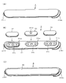
- FIG. 1 is a diagram for explaining the appearance of an electronic pen 1 and side mounting members 2, 3, and 4 according to an embodiment.
- the electronic pen 1 includes a cylindrical housing 11 that is tapered on the pen tip side and has an opening at the tip. Inside the housing 11, a core body 12 is attached to project the pen tip from an opening at the tip of the housing 11. Also, although details will be described later, a ferrite core, a coil, a writing pressure detection unit, a circuit board, and the like are mounted. An electronic pen function unit is installed to realize the electronic pen function.
- a side opening 11H is provided on the side of the housing 11 on the pen tip side, as shown in FIG. 1(A).
- a side switch unit (side switch operating portion) for pressing a switch originally provided on a circuit board mounted on the housing 11 is attached to the side opening 11H.
- a plurality of types of side attachment members can be attached to and detached from the side opening 11H of the housing 11 .
- three types of side mounting members 2, 3 and 4 are detachable.
- the side mounting member 2 shown in FIG. 1(B) functions as a lid member that closes the side opening 11H of the housing 11. As shown in FIG.
- the side mounting member 2 is hereinafter referred to as the lid member 2 .
- the cover member 2 When the cover member 2 is attached to the side opening 11H, the switch provided on the circuit board mounted inside the housing 11 cannot be operated, and the side switch function becomes unavailable. .
- the side mounting member 3 shown in FIG. 1(C) is a side switch unit consisting of one or more push-down knobs (push-down buttons) and a plate portion to which the push-down knobs are attached.
- the side mounting member 3 is hereinafter referred to as a side switch unit 3 .
- the side mounting member 4 shown in FIG. 1(D) is a touch sensor unit (touch sensor operation section) consisting of a capacitive or pressure-sensitive touch sensor and a plate section to which the touch sensor is attached.
- the side mounting member 4 is hereinafter referred to as the touch sensor unit 4 .
- the touch sensor unit 4 When the touch sensor unit 4 is attached to the side opening 11H, the switches provided on the circuit board mounted inside the housing 11 cannot be operated. Operation input through is possible.
- the three types of side mounting members 2, 3, and 4 can be easily attached to and detached from the side opening 11H of the housing 11 of the electronic pen 1.
- the user of the electronic pen 1 selects an appropriate one from the cover member 2, the side switch unit 3, and the touch sensor unit 4 in consideration of what kind of input is to be performed using the electronic pen 1. can be attached to the electronic pen 1 and used.
- FIGS. 2A, 2B, and 2C are diagrams for explaining configuration examples of the lid member 2, the side switch unit 3, and the touch sensor unit 4 as the side mounting member of the embodiment.
- the size (width, length, thickness) and outer edge shape of the lid member 2, the side switch unit 3, and the touch sensor unit 4 are all the same. It is.
- the lid member 2, the side switch unit 3, and the touch sensor unit 4 differ in whether or not they are equipped with functions, and, if they are equipped with functions, in the functions they are equipped with.
- Each of the lid member 2, the side switch unit 3, and the touch sensor unit 4 will be described below.
- FIG. 2A is a diagram for explaining a configuration example of the lid member 2.
- the cover member 2 is made of, for example, a resin material and formed in a plate shape, and is used to close the side opening 11H of the housing 11, and does not have other functions.
- the resin material constituting the lid member 2 for example, polyacetal resin (POM), polyamide resin (PA), polyethylene terephthalate resin (PET), polycarbonate resin (PC), ABS resin, etc. can be used. be.
- the lid member 2 has the same shape as the side opening 11H of the housing 11 of the electronic pen 1, and has a slightly smaller area than the side opening 11H. It is sized to fit within the opening 11H. That is, the lid member 2 is slightly shorter in width (length in the direction perpendicular to the axial direction) and overall length (length in the axial direction) than the side opening 11H. The thickness of the lid member 2 is such that the top surface of the lid member 2 substantially matches the side surface of the housing 11 when the lid member 2 is attached to the side opening 11H of the housing 11 .
- the lid member 2 is provided with a semi-cylindrical engaging portion 21FT near the bottom surface on the pen tip side so as to protrude toward the pen tip side. Further, the lid member 2 has a pressed portion 21BK on the side surface on the rear end side.
- the engaging portion 21FT of the lid member 2 is a portion that engages with the inner wall surface of the housing 11, and the pressed portion 21BK of the lid member 2 is pressed by a pressing mechanism provided inside the housing 11, which will be described later in detail. This is the portion that is pressed forward.
- the end of the pen tip side (engagement portion 21FT side) of the lid member 2 is obliquely inserted so as to abut against the pen tip side end of the side opening 11H of the housing 11, and the rear end side (cover The pressing portion 21BK side) is pushed down toward the side opening 11H, and attached to the side opening 11H.
- the lid member 2 has the engaging portion 21FT engaged with the inner wall surface of the housing 11, and the pressed portion 21BK is pushed toward the pen tip portion (one end side) by the pressing mechanism inside the housing 11. It can be attached to the side opening 11H portion of the housing 11 by being pressed.
- the pressed portion 21BK on the rear end side of the lid member 2 has a stepped shape because the pressed portion 21BK projecting toward the rear end side is pushed into the rear end side of the housing 11, The entire lid member 2 can be slidably moved to the rear end side. As a result, the engagement of the engaging portion 21FT with the inner wall surface of the housing is released so that the lid member 2 can be removed from the side opening 11H of the housing 11 . In this manner, the lid member 2 can be easily attached to the side opening 11H of the housing 11, and can be firmly maintained in the attached state. It can also be removed from the part 11H.
- FIG. 2B is a diagram for explaining a configuration example of the side switch unit 3.
- the side switch unit 3 includes a plate portion 31 and three push-down knobs (operation buttons) attached thereto, a first push-down knob 32 , a second push-down knob 33 , and a third push-down knob 34 .
- Each of the first push-down knob 32, the second push-down knob 33, and the third push-down knob 34 is made of hard rubber, for example.
- the push-down projections and mounting projections are provided on the back surfaces of the push-down knobs 32, 33, and 34, respectively, so they are not shown in FIG. 2(B).
- the surface (operation surface) of the second push-down knob 33 is provided with an operation surface projection 33TP.
- the user can confirm that the user is touching the second push-down knob 33 by touching the operation surface projection 33TP of the second push-down knob 33 with his/her finger, without looking at the side switch unit 3. , and it can be recognized that there are push-down knobs before and after it.
- the operation surface projection 33TP of the second push-down knob 33 allows the user to grasp the positions of the push-down knobs 32, 33, and 34 by touching and recognizing the side switch unit 3 without looking at the side switch unit 3. I have to.
- the plate portion 31 is formed using a metal material or various resin materials as in the case of the lid member 2 described above.
- the plate portion 31 includes a first mounting portion 31a to which the first push-down knob 32 is mounted, a second mounting portion 31b to which the second push-down knob 33 is mounted, and a third mounting portion 31c to which the third push-down knob 34 is mounted.
- a first mounting portion 31a to which the first push-down knob 32 is mounted a second mounting portion 31b to which the second push-down knob 33 is mounted
- a third mounting portion 31c to which the third push-down knob 34 is mounted.
- Each of the first mounting portion 31a, the second mounting portion 31b, and the third mounting portion 31c has, as shown in FIG. Small mounting holes are provided on the front and rear of the knob, into which mounting projections of corresponding push-down knobs are fitted.
- Each of the first mounting portion 31a, the second mounting portion 31b, and the third mounting portion 31c has a substantially rectangular shape.
- the plate portion It does not protrude from the upper surface of 31.
- the first mounting part 31a is connected to the plate part 31 through the first support part 31ax on the rear end side (the right side in FIG. 2(B)), and the other parts are not in contact with the plate part 31.
- the second mounting portion 31b is connected to the plate portion 31 through the second support portion 31bx on the rear end side, and the other portions are not in contact with the plate portion 31.
- the third mounting portion 31c is connected to the plate portion 31 through the third support portion 31cx on the rear end side, and the other portions are not in contact with the plate portion 31. As shown in FIG.
- the plate portion 31 shown in FIG. 2B has the same shape as the side opening 11H of the housing 11 of the electronic pen 1, similarly to the lid member 2 shown in FIG.
- the area is slightly smaller than that, and is sized to fit within the side opening 11H. That is, the plate portion 31 is slightly shorter in width and overall length than the side opening 11H.
- the thickness of the plate portion 31 is such that when the plate portion 31 is attached to the side opening portion 11H of the housing 11, the top surface of the plate portion 31 substantially matches the side surface of the housing 11. It has become.
- the plate portion 31 shown in FIG. 2B also has a semi-cylindrical engagement portion near the bottom surface of the pen tip so as to protrude toward the pen tip. It has a junction 31FT. Further, the plate portion 31 has a pressed portion 31BK on the side surface on the rear end side.
- the engaging portion 31FT of the plate portion 31 is a portion that engages with the inner wall surface of the housing 11, and the pressed portion 31BK of the plate portion 31 is pressed by a pressing mechanism provided in the housing 11, which will be described later in detail. This is the portion that is pressed forward.
- the side switch unit 3 formed by attaching the first push-down knob 32, the second push-down knob 33, and the third push-down knob 34 to the plate portion 31 is attached to the side opening 11H portion of the housing 11.
- the pen tip side (engagement portion 31FT side) of the side switch unit 3 is obliquely inserted so as to abut against the end side of the pen tip side of the side opening 11H of the housing 11, and the rear end side (pressed 31BK side) is pushed down toward the side opening 11H.
- the engaging portion 31FT of the side switch unit 3 is engaged with the inner wall surface of the housing 11, and the pressed portion 31BK is pressed toward the pen tip by the pressing mechanism inside the housing 11. can be attached to the side opening 11H portion of the
- the pushed portion 31BK projecting toward the rear end side is pushed toward the rear end side of the housing 11, whereby the side switch unit 3 as a whole moves backward.
- the engagement of the engaging portion 31FT can be released by slidably moving to the end side.
- the side switch unit 3 is not only easily attached to the side opening 11H of the housing 11, but also can be easily removed from the side opening 11H of the housing 11 as required. .
- FIG. 2C is a diagram for explaining a configuration example of the touch sensor unit 4.
- the touch sensor unit 4 is formed, for example, by providing a touch sensor section 42 on a plate section 41 made of various resins.
- the touch sensor section 42 is formed by covering a sheet-shaped touch sensor with an elastomer, as will be described later in detail.
- the plate portion 41 can be formed using various resins in the same manner as the lid member 2 described above.
- the touch sensor unit 4 also has the same shape and size as the lid member 2 shown in FIG. 2(A). Further, the plate portion 41 of the touch sensor unit 4 is provided with a semi-cylindrical engaging portion 41FT near the bottom surface on the pen tip side so as to protrude toward the pen tip side. Further, the plate portion 41 has a side surface on the rear end side that is a pressed portion 41BK.
- the engaging portion 41FT of the touch sensor unit 4 is a portion that engages with the inner wall surface of the housing 11, and the pressed portion 41BK of the touch sensor unit 4 is a pressing mechanism provided inside the housing 11, which will be described later in detail. This is the portion that is pressed toward the pen tip side by These points are also the same as those of the lid member 2 described above.
- the pen tip side (engaging portion 41FT side) of the touch sensor unit 4 is obliquely inserted so as to abut against the pen tip side end side of the side opening 11H of the housing 11, and the rear end side (pressed 41BK side) is pushed down toward the side opening 11H.
- the engaging portion 21FT of the touch sensor unit 4 is engaged with the inner wall surface of the housing 11, and the pressed portion 21BK is pressed toward the pen tip by the pressing mechanism inside the housing 11. can be attached to the side opening 11H portion of the
- the touch sensor unit 4 as in the case of the cover member 2, the pressed portion 41BK projecting toward the rear end side is pushed toward the rear end side of the housing 11, thereby completely covering the touch sensor unit 4.
- the engagement of the engaging portion 41FT can be released by sliding it to the rear end side.
- the touch sensor unit 4 can be easily attached to the side opening 11H portion of the housing 11, and can also be easily removed from the side opening 11H portion of the housing 11 as necessary. .
- FIG. 3 is a diagram for explaining a configuration example of the touch sensor unit 4 according to the embodiment.
- 3A is a cross-sectional view of the touch sensor unit 4
- FIG. 3B is a cross-sectional view of the touch sensor section 42 of the touch sensor unit 4.
- FIGS. 3C and 3D are diagrams showing examples of arrangement of touch sensors of different types with different detection methods.
- the two types of touch sensors with different detection methods are a pressure-sensitive (resistive film) sensor and a capacitive sensor.
- connection terminal 42T is led out from the touch sensor section 42, and is provided on a circuit board mounted in the housing 11 when the touch sensor unit 4 is attached to the side opening 11H portion of the housing 11. It is designed to be connected to a connection terminal. Thereby, the detection output from the touch sensor section 42 can be supplied to the circuit board.
- the touch sensor unit 42 is configured by stacking substrate Bd1 ⁇ pressure-sensitive sensors CH5 and CH6 ⁇ substrate Bd2 ⁇ capacitive sensors CH1, CH2, CH3, and CH4 in this order from the bottom (plate portion 41 side).
- Capacitive sensors CH1, CH2, CH3, and CH4 are arranged on a substrate Bd2 that is in the same plane as shown in FIG. 3(B). That is, as shown in FIGS. 3B and 3C, the capacitive sensors CH1, CH2, CH3, and CH4 are arranged in the axial direction of the electronic pen (the direction indicated by the arrow Ar in FIG. It is an array.
- Capacitive sensors CH1, CH2, CH3, and CH4 are capable of detecting changes in capacitance between fingertips and conductive films to detect whether or not they have been operated. It is possible to detect it by itself.
- the pressure-sensitive sensors CH5 and CH6 are arranged in a direction that intersects the axial direction of the electronic pen (direction indicated by arrow Cr in FIG. 3(D)). Since FIG. 3B is a cross-sectional view when viewed from the front side of FIG. It does not appear in (B).
- the pressure-sensitive sensor CH5 is configured by bonding a first electrode FE1 and a second electrode FE2 with an adhesive layer Ads.
- a voltage is applied to one of two opposing electrodes (resistive films). It is possible to detect whether or not the button has been pressed by generating a voltage. Therefore, unlike the capacitive sensors CH1, CH2, CH3, and CH4, the pressure-sensitive sensor CH5 does not generate a voltage just by bringing a fingertip close to it, and does not produce a detection output unless a certain amount of pressure is applied. It is.
- the pressure-sensitive sensor CH6 is also constructed in the same manner as the pressure-sensitive sensor CH5.
- the capacitive sensors CH1, CH2, CH3, and CH4 are capable of detecting when the user's fingertips come close to a certain distance.
- the pressure-sensitive sensors CH5 and CH6 cannot detect that they are being operated unless they are pressed with a certain amount of force.
- substrate Bd1 ⁇ pressure-sensitive sensors CH5 and CH6 ⁇ substrate Bd2 ⁇ capacitive sensors CH1, CH2, CH3, and CH4 are laminated in this order.
- the touch sensor unit 42 (FIG. 3(B)) is configured as a result.
- the operation is only detected by the capacitive sensors CH1, CH2, CH3, and CH4.
- a pressing operation is performed so as to apply pressure equal to or greater than a predetermined value on the touch sensor section 42 .
- the capacitance sensors CH1, CH2, CH3, and CH4 the capacitance sensors corresponding to the depressed portions and the pressure-sensitive sensors CH5 and CH6 located below them are simultaneously pressed. can be detected.
- the touch sensor unit 4 can accept slide operation input for which only the capacitive sensors CH1, CH2, CH3, and CH4 of the touch sensor section 42 function. Also, the touch sensor unit 4 can accept a press operation input in which both the capacitive sensors CH1, CH2, CH3, CH4 and the pressure-sensitive sensors CH5, CH6 function simultaneously. Also, by considering the position of the sensor that detects the operation input, it is possible to receive a plurality of different types of operation input.
- the electronic pen 1 of this embodiment can be used by freely replacing the lid member 2, the side switch unit 3, and the touch sensor unit 4. Therefore, the user can attach the lid member 2 to the electronic pen 1 and disable the side switch function when, for example, handwriting character input is performed. Further, for example, when creating an image using CG technology, the side switch unit 3 is attached to the electronic pen 1, and the side switch function is frequently used, the airbrush function is used, line type, color, etc. are used. can be freely drawn by frequently changing the Further, for example, when editing a sentence, the touch sensor unit 4 is attached to the electronic pen 1, and while the screen is freely scrolled, cutting out, moving, adding a document, etc. are performed, and the editing work is performed. can be done smoothly.
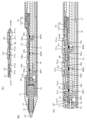
- FIG. 4 is a cross-sectional view of the side switch unit 3 and the electronic pen 1 as side mounting members of the embodiment.
- FIG. 4A is a cross-sectional view of the side switch unit 3 cut in half along the axial direction.
- the side switch unit 3 includes a plate portion 31, a first push-down knob 32, a second push-down knob 33, and a third push-down knob .
- the plate portion 31 includes a first mounting portion 31a, a second mounting portion 31b, and a third mounting portion 31c, as shown in FIG. 2B.
- the first pressing knob 32 is attached to the first attaching portion 31a
- the second pressing knob 33 is attached to the second attaching portion 31b
- the third pressing knob 34 is attached to the third attaching portion 31c.
- the side switch unit 3 is configured.
- each of the first to third push-down knobs 32, 33, and 34 has a push-down projection in the central portion of the lower surface and mounting projections in front and behind the corresponding first to third attachment points. It is mounted by being fitted into the push-down projection holes of the portions 31a, 31b, and 31c and the mounting holes in front and behind thereof.
- the first mounting portion 31a is connected to the plate portion 31 by the first support portion 31ax, and the other portion is not connected to the plate portion 31.
- the second mounting portion 31b is connected to the plate portion 31 by the second support portion 31bx, and is not connected to the plate portion 31 at other portions.
- the third mounting portion 31c is connected to the plate portion 31 by the third support portion 31cx, and is not connected to the plate portion 31 at other portions.
- the thickness of the first push-down knob 32 is thinner than the thicknesses of the second push-down knob 33 and the third push-down knob 34 .
- the operation surface projection 33TP is provided on the surface of the operation portion of the second push-down knob 33 .
- the thickness of these push-down knobs 32, 33, and 34 and the operation surface projection 33TP of the second push-down knob 33 allow the user to recognize which push-down knob his or her finger is touching. As a result, the user can appropriately press down the desired push-down knobs 32 , 33 , 34 without looking at the side switch unit 3 .
- the push knobs 32, 33, and 34 may all have different thicknesses, or may all have the same thickness.
- a metal plate (metal piece) 35 is fixed between the second mounting portion 31b and the third mounting portion 31c.
- the metal plate 35 together with a magnet provided inside the housing 11, which will be described later, holds the side switch unit in an appropriate position with respect to the housing 11 when the side switch unit 3 is attached to the side opening 11H portion of the housing 11. It functions as a positioning part that enables the attachment of 3.
- the metal plate 35 also functions as a holding portion that prevents the side switch unit 3 from easily coming off from the side opening 11H of the housing 11, together with a magnet provided inside the housing 11, which will be described later.
- FIG. 4B is a cross-sectional view of the electronic pen 1 when the side switch unit 3 is not attached to the side opening 11H of the housing 11, and the electronic pen 1 is axially aligned.
- 2 is a cross-sectional view of a portion from the pen tip to the vicinity of the central portion of the electronic pen 1 when cut in half.
- FIG. 4B includes the entire side opening 11H from the tip of the pen, but the rear end portion is omitted.
- the electronic pen function unit is mounted inside the housing 11 .
- the core 12 is inserted from the rear end of the core 12 through the tapered opening of the pen tip side of the housing 11 to form a pipe-shaped ferrite core. 13 to be attached to the writing pressure detection unit 15 .
- a coil 14 that forms a resonance circuit together with a capacitor mounted on a circuit board 17 (to be described later) is wound around the side surface of the ferrite core 13 .
- the core body 12 protrudes the pen tip from the opening at the tip of the tapered portion of the housing 11, and the core body 12 slides in the axial direction according to the writing pressure applied to the pen tip. It's becoming That is, the core body 12 is pushed into the housing 11 and moves toward the writing pressure detection unit 15 when the writing pressure is applied, and is pushed back to the original position when the writing pressure is released.
- the writing pressure detection unit 15 is configured as a variable capacitor, and detects the writing pressure according to the capacitance that changes according to the writing pressure applied to the core 12 .
- a circuit board 17 on which various circuit components such as push-down switches SW1, SW2, and SW3 that realize the side switch function, a capacitor, and a control IC are mounted is provided behind the writing pressure detection unit 15 .
- the circuit board 17 is placed on a half-pipe-shaped board holding member 16 whose upper side, which is the circuit board 17 side, is open, and is fixed in position within the housing 11 . That is, the substrate holding member 16 is fixed inside the housing 11 .
- an inverted half-pipe-shaped board protection member 18 with an opening on the lower side, which is on the side of the circuit board 17, is provided. You can't touch it.
- the board protection member 18 is provided with a first pressing portion 18a at a portion facing the first mounting portion 31a of the plate portion 31 of the side switch unit 3 when the side switch unit 3 is mounted in the side opening portion 11H. ing.
- a second pressing portion 18b is provided in the portion of the board protection member 18 that faces the second mounting portion 31b of the plate portion 31, and the board protection member 18 faces the third mounting portion 31c of the plate portion 31.
- a portion 18 is provided with a third pressing portion 18c.
- a pressing protrusion is provided on the lower side of the first pressing portion 18a so that the switch SW1 of the circuit board 17 can be pressed by this protrusion.
- a pressing projection is provided on the lower side of the second pressing portion 18b so that the switch SW2 on the circuit board 17 can be pressed.
- a pressing projection is provided on the lower side of the third pressing portion 18c so that the switch SW3 on the circuit board 17 can be pressed.
- first pressing portion 18a of the substrate protection member 18 is connected to the substrate protection member 18 through the first support portion 18ax, and the other portion is not connected to the substrate protection member 18.
- second pressing portion 18b of the substrate protection member 18 is connected to the substrate protection member 18 through the second support portion 18bx, and is not connected to the substrate protection member 18 at other portions.
- third pressing portion 18c is connected to the substrate protection member 18 through the third support portion 18cx, and is not connected to the substrate protection member 18 at other portions.
- a magnet 19 is fixed at a position on the pen tip side of the third support portion 18cx.
- the magnet 19 attracts the metal plate 35 of the side switch unit 3, functions as a positioning portion for the side switch unit 3, and also functions as a holding portion for holding the side switch unit 3 in the side opening portion 11H.
- a pressing mechanism 70 is provided on the top surface of the substrate protection member 18 on the rear end side.
- the pressing mechanism portion 70 includes a pressing member 71 and a coil spring 72 that is an elastic member.
- the pressing member 71 is positionally regulated so as not to protrude toward the tip of the pen more than necessary or be pushed toward the rear end more than necessary.
- the pressing member 71 is always urged toward the pen tip side by a coil spring 72, but when it is pushed toward the rear end side, the coil spring 72 shrinks so that it can slide toward the rear end side. It has become.
- FIG. 5 is a diagram for explaining the pressing mechanism section 70 of the electronic pen according to the embodiment.
- a rear end portion of the substrate protection member 18 serves as a mounting recess in which the pressing member 71 and the coil spring 72 are mounted.
- the pressing member 71 includes a pressing plate portion 71a, which is a plate-like body having an arc-shaped concave portion on the tip surface so as to match the pressed portion 31BK on the rear end side of the side switch unit 3, and a pressing plate portion 71a. and a rod-shaped portion 71b extending from the center of the end face toward the rear end side.
- a coil spring 72 is wound around the bar-shaped portion 71b.
- Recesses 71L and 71R are provided on the left and right side surfaces of the pressing plate portion 71a. Further, when the pressing member 71 is placed in the mounting recess of the substrate protection member 18, the left and right recesses of the substrate protection member 18 are placed at the positions corresponding to the left and right recesses 71L and 71R of the pressing plate portion 71a. Protrusions 18L and 18R projecting from the inner surface are provided. The pressing member 71 and the coil spring 72 are mounted in the mounting recess of the board protection member 18 as shown in FIG.
- the pressing member 71 is mounted in the mounting recess of the substrate protection member 18 so that the rear end side of the bar-shaped portion 71b around which the coil spring 72 is wound is hidden behind the arch portion 18AH at the rear end of the substrate protection member 18. be.
- the convex portion 18L protruding from the left inner side surface of the mounting concave portion of the substrate protection member 18 enters into the concave portion 71L on the left side surface of the pressing plate portion 71a, and the concave portion 71R on the right side surface of the pressing plate portion 71a
- a protrusion 18L protruding from the right inner side surface of the mounting recess of the substrate protection member 18 enters.
- the pressing member 71 and the coil spring 72 are mounted on the mounting recess on the rear end side of the board protection member 18 so as not to come off or shift.
- the axial lengths of the concave portions 71L and 71R of the pressing plate portion 71a are longer than the axial lengths of the convex portions 18L and 18R of the board protection member 18 .
- the length (depth of the recess) of the recesses 71L and 71R of the pressing plate portion 71a in the direction intersecting the axial direction is the length of the projections 18L and 18R of the substrate protection member 18 in the direction intersecting the axial direction. It is slightly longer (deeper) than the height (the length of the overhang of the convex portion) or approximately the same length.
- the pressing member 71 can slide in the axial direction within a range restricted by the left and right protrusions 18L and 18R of the substrate protection member 18. As shown in FIG. That is, the pressing member 71 is prevented from protruding more than necessary toward the tip of the pen or entering toward the rear end more than necessary.
- the rod-shaped portion 71b of the pressing member 71 is provided with a coil spring 72 so as to be wound thereon, and this is attached to the rear end surface of the pressing plate portion 71a and the rear end inner wall surface of the mounting recess of the substrate protection member 18.
- the pressing plate portion 71a is urged toward the pen tip side at all times. However, if the pressing plate portion 71a is pushed rearward, the coil spring 72 is contracted and can be slid to the rear end side within the range restricted by the convex portions 18L and 18R of the substrate protection member 18.
- the side switch unit 3 when the side switch unit 3 is attached, the side switch unit 3 can be firmly attached to the side opening 11H portion of the housing 11 by the action of the pressing mechanism 70 and maintained in that state. However, it is also possible to slide the pressing member 71 by pushing it toward the rear end side, so that the side switch unit 3 can be easily removed.
- FIG. 4C is a cross-sectional view of the electronic pen 1 when the side switch unit 3 is attached to the side opening 11H portion of the housing 11, and the electronic pen 1 is cut in half along the axial direction. It is an enlarged view centering on the side opening 11H portion when cut.
- the pen point side of the side switch unit 3 shown in FIG. 4A is tilted downward, and the engaging portion 31FT is inserted into the gap gp between the board protection member 18 and the housing 11 shown in FIG. 4B. , and push the rear end of the side switch unit 3 toward the side opening 11H.
- the side switch unit 3 can be attached to the side opening 11H of the housing 11 of the electronic pen 1, as shown in FIG. 4(C).
- the engaging portion 31FT of the side switch unit 3 engages with the inner wall surface of the housing 11 on the pen tip side of the side opening 11H. Further, the pressed portion 31BK at the rear end of the side switch unit 3 is pressed toward the pen tip by the pressing member 71 of the pressing mechanism portion 70 provided on the rear end side of the board protection member 18 . Furthermore, the metal plate 35 of the side switch unit 3 is attracted to the magnet 19 of the board protection member 18 .
- the side switch unit 3 can be attached to the proper position of the side opening 11H portion of the housing 11 of the electronic pen 1, and can be prevented from being easily removed due to the confusion of these three functions.
- the user touches the upper surface of the side switch unit 3 with his finger and touches the rear end side of the electronic pen 1. to push up.
- the side switch unit 3 is slid to the rear end side of the electronic pen 1 .
- the side switch unit 3 is slidably moved to the rear end side of the electronic pen 1 together with the pressing member 71 of the pressing mechanism section 70, and the inner side of the housing 11 at the pen tip side end portion of the side opening 11H.
- the engagement between the wall surface and the engagement portion 31FT on the pen point side of the side switch unit 3 is released.
- the pen tip side of the side switch unit 3 can be separated from the housing 11 of the electronic pen 1, so the pen tip side of the side switch unit 3 is lifted.
- the metal plate 35 of the side switch unit 3 is separated from the magnet 19 of the board protection member 18, and the pressing of the pressing member 71 of the pressing mechanism 70 to the pressed portion 31BK of the side switch unit 3 is released. .
- the side switch unit 3 can be easily removed from the side opening 11H.
- the side switch unit 3 is attached to and detached from the side opening 11H portion of the housing 11 of the electronic pen 1 . It can be put on and taken off in the same way. That is, when mounting, the cover member 2 and the touch sensor unit 4 are tilted with the pen tip side inclined so that the space gp between the board protection member 18 and the housing 11 shown in FIG. Insert joints 21FT and 41FT. Further, the lid member 2 and the rear end portions of the touch sensor unit 4 are pushed toward the side opening portion 11H. As a result, the lid member 2 and the touch sensor unit 4 can be easily attached to the side opening 11H of the housing 11 .
- the lid member 2 and the touch sensor unit 4 When removing, the lid member 2 and the touch sensor unit 4 are pushed up toward the rear end side of the electronic pen 1 and slidably moved to engage the inner wall surface of the housing 11 and the engaging portions 21FT and 41FT. remove the joint. After that, if the pen tip side of the cover member 2 and the touch sensor unit 4 is lifted, the pressed portions 21BK and 41BK of the cover member 2 and the touch sensor unit 4 are also pressed by the pressing member 71 of the pressing mechanism 70. be released. As a result, the lid member 2 and the touch sensor unit 4 can be easily removed from the side opening 11H.
- the lid member 2 and the touch sensor unit 4 may also be provided with metal plates (metal pieces) at the same positions as the metal plate 35 of the side switch unit 3 .
- the metal plate is attracted by the magnet 19 of the substrate protection member 18, and the cover member 2 and the touch sensor unit 4 are attached to appropriate positions, and easily removed from the side opening 11H portion of the housing 11. You can make sure it doesn't happen.
- the electronic pen 1 of this embodiment has a thin shaft as a whole. For this reason, some users may wish to make the shaft portion of the electronic pen 1 that they hold in their hand thicker. Therefore, it is considered that the electronic pen 1 is equipped with a post-installed grip member that thickens the shaft portion. In this case, the mounting of the side mounting member such as the side switch unit becomes a problem. In other words, if only the side opening is provided in the retrofitted grip member, the thickness of the grip member becomes an obstacle and the side switch function cannot be properly used. Therefore, a side mounting member such as a side switch unit corresponding to the retrofitted grip member can be used.
- FIG. 6 is a diagram for explaining an example of the grip member 5 that can be attached to the electronic pen 1 of the embodiment and the side attachment member 6 that can be used when the grip member 5 is attached to the electronic pen 1.
- the side mounting member 6 shown in FIG. 6 is an example of a side switch unit.
- the retrofitted grip member 5 is a cylindrical body with openings at the front end surface and the rear end surface.
- a side opening 5H is provided to match the side opening 11H of the body 11.
- the thickness of the grip member 5 in the direction orthogonal to the axial direction is a thickness h1 as shown in FIG. 6A, and the shaft portion of the electronic pen 1 can be thickened by this thickness h1.
- the side switch unit 6 used together with the grip member 5 is similar to that of the side switch unit 3 described with reference to FIGS. 2(B) and 4(A). Therefore, the side switch unit 6 comprises a plate portion 61, a first push-down knob 62, a second push-down knob 63, and a third push-down knob 64, as shown in FIG. 6(B).
- An engaging portion 61FT corresponding to the engaging portion 31FT of the side switch unit 3 is provided on the bottom side of the front end surface of the side switch unit 6, and the bottom side of the rear end surface is covered by the side switch unit 3.
- the pressed portion 61BK corresponds to the pressed portion 31BK.
- the thickness of the plate portion 61 (the thickness in the direction intersecting the axial direction) is the thickness h2 that is the sum of the thickness of the housing 11 of the electronic pen 1 and the thickness h1 of the grip member 5 .
- the plate portion 61 of this example also has the same configuration as the plate portion 31 shown in FIG. 2(B). That is, although not shown, it has a first mounting portion 61a, a second mounting portion 61b, and a third mounting portion 61c. Also in this example, the first mounting portion 61a is connected to the plate portion 61 by the first support portion 61ax, the second mounting portion 61b is connected to the plate portion 61 by the second support portion 61bx, and the third mounting portion 61c is connected to the plate portion 61 by the second support portion 61bx. It is connected to the plate portion 61 by 3 support portions 61cx.
- Each of the first mounting portion 61a, the second mounting portion 61b, and the third mounting portion 61c is attached to the plate portion 61 except for the portions connected by the first support portion 61ax, the second support portion 61bx, and the third support portion 61cx. is not connected.
- the thicknesses of the first mounting portion 61a, the second mounting portion 61b, and the third mounting portion 61c are basically the same as those of the first mounting portion 31a, the second mounting portion 31b, and the third mounting portion shown in FIG. 31c.
- the push-down protrusions provided in the central portion of the lower surface of the first push-down knob 62, the second push-down knob 63, and the third push-down knob 64 have a length corresponding to the thickness h2 of the plate portion 61.
- the push-down knobs provided at the center of the lower surface of the first push-down knob 62, the second push-down knob 63, and the third push-down knob 64 of the side switch unit 6 are designed to protect the substrate in the manner shown in FIG. 4(C). It contacts central portions of the first pressing portion 18a, the second pressing portion 18b, and the third pressing portion 18c of the member.
- the grip member 5 is not limited to the one shown in FIG. 5, and grip members with various designs that can be attached to the shaft of the electronic pen 1 can be used.
- the grip member 5 may be formed using various elastomers, which are polymeric materials having elasticity, such as natural rubber and synthetic rubber, or may be formed using various materials such as metal, wood, and hard resin. You can
- the side switch unit 6 is used as the side mounting member has been described here as an example.
- the lid member and the touch sensor unit can also be configured to have an increased thickness in the direction intersecting the axial direction.
- a cover member and a touch sensor unit corresponding to the grip member 5 attached later can be configured.
- the side switch function can be disabled in the same manner as when the cover member 2 is attached.
- the mode of use of the side switch function can be flexibly changed in the same manner as when the grip member 5 is not attached. be able to.
- the side switch unit 3 is provided with the three push-down knobs 32, 33, 34, and the side switch unit is provided with the three push-down knobs 62, 63, 64.
- the number of push-down knobs of the side switch unit such as a side switch unit having two push-down knobs or a side switch unit having one push-down knob, can be set appropriately within an operable range.
- the circuit board 17 of the electronic pen 1 may be provided with switches corresponding to the number of push-down knobs of the side switch unit. Two or any one may be used.
- the touch sensor unit 4 it is possible to use only a capacitive touch sensor or only a pressure sensitive touch sensor. Also, in this case, the arrangement of the touch sensors can be various arrangements. Of course, even when a capacitive touch sensor and a pressure-sensitive touch sensor are used, various arrangements and stacking orders can be used.
- the lid member, the side switch units 3 and 6, and the touch sensor unit 4 can have various sizes according to the size of the side opening 11H provided in the housing 11 of the electronic pen 1.
- the operation surface projection 33TP is provided on the operation surface of the second push-down knob 33, but the present invention is not limited to this.
- the operation surface projection 33TP can be omitted, or can be provided on the operation surface of another push-down knob.
- the side switch unit 3 is provided with the metal plate 35, and the board protection member 18 is provided with the magnet 19 at the corresponding position.
- the side switch unit 3 may be provided with a plurality of metal plates, and the board protection member 18 may also be provided with magnets at positions corresponding to the plurality of metal plates of the side switch unit 3 .
- the plate portions 31, 61 of the side switch units 3, 6 can be made of various metal materials, the weight can be changed according to the type of metal material. As a result, when it is desired to realize a so-called electronic pen 1 with a low center of gravity, the side switch unit 3 in which the plate portion 31 is formed using a heavy metal material can be used. Further, when an electronic pen that is light overall is realized, it is possible to use the side switch unit 3 in which the plate portion 31 is formed using a light metal material.
- the side mounting members such as the lid member 2, the side switch unit 3, and the touch sensor unit 4 can be freely, easily, and appropriately attached and detached, new functions can be added using this.
- the electronic pen 1 is of the active capacitive type, power is required to drive the oscillator in order to send out signals from the core.
- a charging terminal that can be connected when the side mounting member is removed to expose the inside of the housing 11 is provided, and the charging terminal is passed through the charging terminal. Battery charging can be enabled.
- the engaging portion 31FT is provided at the end on the pen tip side, and the pressed portion 31BK is provided on the rear end side.
- the end of the side switch unit 3 on the side of the pen tip may be used as the pressed portion, and the engaging portion may be provided on the end on the rear end side.
- a pressing mechanism 70 may be provided on the pen tip side of the board protection member 18 to press the side mounting member from the pen tip side toward the rear end side.
- the lid member 2, the touch sensor unit 4, and the side switch unit 6 can also have the same configuration.
Abstract
The present invention achieves an electronic pen capable of flexibly changing the mode of use of a side switch function, in accordance with a need of a user. A side switch unit (3) has an engagement portion (31FT) at one end in an axial direction, and a pressed portion (31BK) at another end. One end side of the side switch unit (3) is obliquely inserted to butt against one end side of a side-surface opening (11H) of a case (11), and another end side is pushed down toward the side-surface opening (11H). The engagement portion (31FT) engages with the case (11), and the pressed portion (31BK) is pressed toward the one end side by a pressing mechanism portion (70), and thereby the side switch unit (3) is attached to the side-surface opening (11H) portion of the case (11).
Description
この発明は、例えば、タブレットPC(Personal Computer)などの電子機器に搭載された位置検出装置に対して、座標を指示することにより情報の入力を可能にする電子ペンに関する。
The present invention relates to an electronic pen that enables information input by indicating coordinates to a position detection device mounted on an electronic device such as a tablet PC (Personal Computer).
例えば、タブレットPC(Personal Computer)やスマートフォンなどと呼ばれる高機能携帯電話端末などの電子機器においては、搭載された位置検出装置を通じて、より細かな描画入力を行うために、電子ペンによる指示入力が可能にされたものがある。このような電子ペンにおいても、いわゆるサイドスイッチを利用可能にしたものが存在する。電子ペンにおけるサイドスイッチは、電子ペンを持ったまま指によって操作が可能なように、電子ペンの側面に設けられたスイッチを意味する。サイドスイッチは、パーソナルコンピュータのポインティングデバイスであるいわゆるマウスのクリックボタンと同様に、指示位置を確定したり、ウィンドウを開いて実行する機能を選択したりするなどのことを可能にする。
For example, in electronic devices such as tablet PCs (Personal Computers) and high-performance mobile phone terminals called smartphones, it is possible to input instructions with an electronic pen in order to perform more detailed drawing input through the built-in position detection device. There is something that has been done. Among such electronic pens, there is a pen that can use a so-called side switch. A side switch in an electronic pen means a switch provided on the side of the electronic pen so that it can be operated with a finger while holding the electronic pen. The side switch makes it possible to confirm a pointed position, open a window and select a function to be executed, etc., in the same way as a so-called click button of a mouse, which is a pointing device of a personal computer.
例えば、CG(Computer Graphics)技術を用いて画像を作成する場合には、サイドスイッチを通じて、エアーブラシ機能を操作したり、使用する色の選択を替えたりするなど、頻繁にサイドスイッチが使用される。これに対して、例えば、文字入力を行う場合には、サイドスイッチを使用することは少ない。このように、サイドスイッチ機能はあっても、実行されるアプリケーションに応じて、サイドスイッチ機能がほとんど使用されない場合もある。このため、後に記す特許文献1には、サイドスイッチ操作部をユニットとして位置指示器(電子ペン)本体に対して着脱可能にする位置指示器に関する発明が開示されている。これにより、サイドスイッチの利用頻度に応じて、サイドスイッチ操作部を付けたり、外したりすることができる。
For example, when creating an image using CG (Computer Graphics) technology, the side switch is frequently used to operate the airbrush function, change the color selection, etc. . On the other hand, for example, the side switch is rarely used when inputting characters. Thus, even if the side switch function is present, the side switch function may be rarely used depending on the application being run. For this reason, Patent Literature 1, which will be described later, discloses an invention relating to a position indicator in which a side switch operating section is detachable as a unit from a body of the position indicator (electronic pen). As a result, the side switch operating portion can be attached or detached according to the frequency of use of the side switch.
特許文献1に開示された発明の場合、サイドスイッチ操作部(サイドスイッチユニット)を位置指示器本体に締め付け用のネジにより固定するので、強固に取り付けることが可能であるが、取り付けや取り外しには手間がかかり面倒である。また、特許文献1に開示された発明の場合、サイドスイッチユニットが位置指示器本体から軸心方向と交差する方向に大きく張り出した構成になっている。このような構成を好む使用者が存在する半面、位置指示器本体からあまり突出しないようにサイドスイッチを設けるようにしたいとする使用者も存在する。また、電子ペンを用いてどのような入力を行うのかに応じて、適切な態様のサイドスイッチ操作部を簡単に付け替えることができればより便利である。
In the case of the invention disclosed in Patent Literature 1, the side switch operating portion (side switch unit) is fixed to the position indicator main body by tightening screws, so it can be firmly attached, but it is difficult to attach and detach. It is time consuming and troublesome. Further, in the case of the invention disclosed in Patent Document 1, the side switch unit is configured to protrude greatly from the position indicator main body in the direction crossing the axial direction. While there are users who prefer such a configuration, there are also users who want the side switch to be provided so as not to protrude from the body of the position indicator. Moreover, it would be more convenient if the side switch operation section could be easily replaced in an appropriate manner according to the type of input to be performed using the electronic pen.
以上のことに鑑み、この発明は、使用者のニーズに応じて、サイドスイッチ機能の利用態様を柔軟に変更することができる電子ペンを実現することを目的とする。
In view of the above, an object of the present invention is to realize an electronic pen that can flexibly change the mode of use of the side switch function according to the user's needs.
上記課題を解決するため、
回路基板を含む電子ペン機能部が搭載されると共に、側面にサイドスイッチを設けるための側面開口部が設けられた筒状の筐体と、
前記筐体の前記側面開口部の部分に対して装着される側面装着部材と
を備え、
前記側面装着部材は、軸心方向の一方の端部に前記筐体に係合する係合部を備え、他方の端部は被押圧部となっており、
前記筐体の内部であって、前記側面開口部の部分に装着された前記側面装着部材の前記被押圧部を、前記一方の端部側に押圧する押圧機構部が設けられている
ことを特徴とする電子ペンを提供する。 In order to solve the above problems,
A cylindrical housing in which an electronic pen function unit including a circuit board is mounted and a side opening for providing a side switch on the side is provided;
a side attachment member attached to the side opening of the housing,
The side mounting member has an engaging portion that engages with the housing at one end in the axial direction, and has a pressed portion at the other end,
A pressing mechanism is provided inside the housing for pressing the pressed portion of the side attachment member attached to the side opening portion toward the one end side. To provide an electronic pen that
この電子ペンによれば、側面装着部材は、軸心方向の一方の端部に係合部が設けられ、他方の端部が被押圧部となっている。側面装着部材を筐体の側面開口部の部分に装着する場合には、一方の端部側が筐体の側面開口部の一方の端部側に突合するように斜めに差し込まれ、他方の端部側が側面開口部に向かうように押し下げられる。これにより、側面装着部材は、一方の端部の係合部が筐体の内側面に係合し、他方の端部の被押圧部が押圧機構部によって一方の端部側に押圧されて筐体の側面開口部の部分に取り付けられる。このように、側面装着部材は、差し込んで押し下げるといった簡単な操作によって、当該筐体の側面開口部の部分に対して取り付け可能にされる。
According to this electronic pen, the side mounting member is provided with an engaging portion at one end in the axial direction, and a pressed portion at the other end. When attaching the side mounting member to the side opening of the housing, one end side is obliquely inserted so as to abut one end side of the side opening of the housing, and the other end is inserted into the side opening of the housing. side is pushed down toward the side opening. As a result, the engaging portion at one end of the side mounting member is engaged with the inner side surface of the housing, and the pushed portion at the other end is pushed toward the one end by the pushing mechanism, thereby mounting the housing. Attached to the side opening part of the body. Thus, the side attachment member can be attached to the side opening of the housing by a simple operation of inserting and pushing down.
以下、図を参照しながらこの発明による電子ペンの実施の形態について説明する。なお、電子ペンには、例えば、電磁誘導方式(EMR(Electro Magnetic Resonance)方式)の電子ペンやアクティブ静電容量方式(AES(Active Electrostatic)方式)の電子ペンなど、種々の方式のものが存在する。この発明は、いわゆるサイドスイッチが設けられる電子ペンであれば、どのような方式の電子ペンに対しても適用可能なものである。以下においては、説明を簡単にするため、電磁誘導方式の電子ペンに適用した場合を例にして説明する。
Embodiments of the electronic pen according to the present invention will be described below with reference to the drawings. There are various types of electronic pens, such as an electromagnetic induction type (EMR (Electro Magnetic Resonance) type) electronic pen and an active capacitance type (AES (Active Electrostatic) type) electronic pen. do. The present invention can be applied to any type of electronic pen as long as it is provided with a so-called side switch. In the following, for the sake of simplification, an example of application to an electromagnetic induction type electronic pen will be described.
[電子ペン及び側面装着部材の外観]
図1は、実施の形態の電子ペン1及び側面装着部材2、3、4の外観を説明するための図である。図1(A)に示すように、電子ペン1は、ペン先側が先細り(テーパー形状)となって、その先端が開口となった筒状体の筐体11を備える。筐体11の内部には、筐体11の先端の開口よりペン先部を突出させる芯体12が取り付けられる他、詳しくは後述するが、フェライトコア、コイル、筆圧検出部、回路基板等の電子ペン機能を実現するための電子ペン機能部が搭載されている。 [Appearance of electronic pen and side mounting member]
FIG. 1 is a diagram for explaining the appearance of an electronic pen 1 and side mounting members 2, 3, and 4 according to an embodiment. As shown in FIG. 1A, the electronic pen 1 includes a cylindrical housing 11 that is tapered on the pen tip side and has an opening at the tip. Inside the housing 11, a core body 12 is attached to project the pen tip from an opening at the tip of the housing 11. Also, although details will be described later, a ferrite core, a coil, a writing pressure detection unit, a circuit board, and the like are mounted. An electronic pen function unit is installed to realize the electronic pen function.
図1は、実施の形態の電子ペン1及び側面装着部材2、3、4の外観を説明するための図である。図1(A)に示すように、電子ペン1は、ペン先側が先細り(テーパー形状)となって、その先端が開口となった筒状体の筐体11を備える。筐体11の内部には、筐体11の先端の開口よりペン先部を突出させる芯体12が取り付けられる他、詳しくは後述するが、フェライトコア、コイル、筆圧検出部、回路基板等の電子ペン機能を実現するための電子ペン機能部が搭載されている。 [Appearance of electronic pen and side mounting member]
FIG. 1 is a diagram for explaining the appearance of an electronic pen 1 and
また、筐体11のペン先側の側面には、図1(A)に示すように、側面開口部11Hが設けられている。側面開口部11Hには、本来、筐体11に搭載された回路基板に設けられているスイッチを押下操作するためのサイドスイッチユニット(サイドスイッチ操作部)が装着される。しかし、この実施の形態の電子ペン1において、筐体11の側面開口部11Hに対しては、複数種類の側面装着部材が着脱可能になっている。この実施の形態においては、図1(B)、(C)、(D)に示すように、3種類の側面装着部材2、3、4が着脱可能にされる。
In addition, a side opening 11H is provided on the side of the housing 11 on the pen tip side, as shown in FIG. 1(A). A side switch unit (side switch operating portion) for pressing a switch originally provided on a circuit board mounted on the housing 11 is attached to the side opening 11H. However, in the electronic pen 1 of this embodiment, a plurality of types of side attachment members can be attached to and detached from the side opening 11H of the housing 11 . In this embodiment, as shown in FIGS. 1B, 1C and 1D, three types of side mounting members 2, 3 and 4 are detachable.
図1(B)に示す側面装着部材2は、筐体11の側面開口部11Hを塞ぐ蓋部材として機能するものである。以下においては、側面装着部材2を蓋部材2と記載する。蓋部材2が、側面開口部11H部分に装着された場合には、筐体11内に搭載された回路基板に設けられているスイッチに対する操作はできないようにされ、サイドスイッチ機能は利用不能となる。
The side mounting member 2 shown in FIG. 1(B) functions as a lid member that closes the side opening 11H of the housing 11. As shown in FIG. The side mounting member 2 is hereinafter referred to as the lid member 2 . When the cover member 2 is attached to the side opening 11H, the switch provided on the circuit board mounted inside the housing 11 cannot be operated, and the side switch function becomes unavailable. .
図1(C)に示す側面装着部材3は、1以上の押下ノブ(押下ボタン)と、これが取り付けられるプレート部とからなるサイドスイッチユニットである。以下においては、側面装着部材3をサイドスイッチユニット3と記載する。サイドスイッチユニット3が、側面開口部11H部分に装着された場合には、筐体11内に搭載された回路基板に設けられているスイッチに対する操作が可能にされ、サイドスイッチ機能は利用可能となる。
The side mounting member 3 shown in FIG. 1(C) is a side switch unit consisting of one or more push-down knobs (push-down buttons) and a plate portion to which the push-down knobs are attached. The side mounting member 3 is hereinafter referred to as a side switch unit 3 . When the side switch unit 3 is attached to the side opening 11H, the switch provided on the circuit board mounted inside the housing 11 can be operated, and the side switch function becomes available. .
図1(D)に示す側面装着部材4は、静電容量方式あるいは感圧方式のタッチセンサと、当該タッチセンサが取り付けられるプレート部からなるタッチセンサユニット(タッチセンサ操作部)である。以下においては、側面装着部材4をタッチセンサユニット4と記載する。タッチセンサユニット4が、側面開口部11H部分に装着された場合には、筐体11内に搭載された回路基板に設けられているスイッチに対する操作は不能となるが、タッチセンサユニット4のタッチセンサを通じての操作入力は可能となる。
The side mounting member 4 shown in FIG. 1(D) is a touch sensor unit (touch sensor operation section) consisting of a capacitive or pressure-sensitive touch sensor and a plate section to which the touch sensor is attached. The side mounting member 4 is hereinafter referred to as the touch sensor unit 4 . When the touch sensor unit 4 is attached to the side opening 11H, the switches provided on the circuit board mounted inside the housing 11 cannot be operated. Operation input through is possible.
このように、電子ペン1の筐体11の側面開口部11H部分には、3種類の側面装着部材2、3、4が簡単に着脱することができるようになっている。このため、電子ペン1の使用者は、電子ペン1を用いてどのような入力を行うのかを考慮して、蓋部材2、サイドスイッチユニット3、タッチセンサユニット4の中から適切なものを選択し、電子ペン1に装着し、利用することができる。
In this way, the three types of side mounting members 2, 3, and 4 can be easily attached to and detached from the side opening 11H of the housing 11 of the electronic pen 1. For this reason, the user of the electronic pen 1 selects an appropriate one from the cover member 2, the side switch unit 3, and the touch sensor unit 4 in consideration of what kind of input is to be performed using the electronic pen 1. can be attached to the electronic pen 1 and used.
[側面装着部材2、3、4の構成例]
図2は、実施の形態の側面装着部材としての蓋部材2、サイドスイッチユニット3、タッチセンサユニット4の構成例を説明するための図である。図2(A)、(B)、(C)に示すように、蓋部材2、サイドスイッチユニット3、タッチセンサユニット4のサイズ(幅、長さ、厚み)及び外縁形状は、いずれも同様のものである。しかし、蓋部材2、サイドスイッチユニット3、タッチセンサユニット4は、機能の搭載の有無、また、機能が搭載されている場合には、その搭載された機能において違いがある。以下、蓋部材2、サイドスイッチユニット3、タッチセンサユニット4のそれぞれについて説明する。 [Configuration example of side mounting members 2, 3, 4]
2A and 2B are diagrams for explaining configuration examples of thelid member 2, the side switch unit 3, and the touch sensor unit 4 as the side mounting member of the embodiment. As shown in FIGS. 2A, 2B, and 2C, the size (width, length, thickness) and outer edge shape of the lid member 2, the side switch unit 3, and the touch sensor unit 4 are all the same. It is. However, the lid member 2, the side switch unit 3, and the touch sensor unit 4 differ in whether or not they are equipped with functions, and, if they are equipped with functions, in the functions they are equipped with. Each of the lid member 2, the side switch unit 3, and the touch sensor unit 4 will be described below.
図2は、実施の形態の側面装着部材としての蓋部材2、サイドスイッチユニット3、タッチセンサユニット4の構成例を説明するための図である。図2(A)、(B)、(C)に示すように、蓋部材2、サイドスイッチユニット3、タッチセンサユニット4のサイズ(幅、長さ、厚み)及び外縁形状は、いずれも同様のものである。しかし、蓋部材2、サイドスイッチユニット3、タッチセンサユニット4は、機能の搭載の有無、また、機能が搭載されている場合には、その搭載された機能において違いがある。以下、蓋部材2、サイドスイッチユニット3、タッチセンサユニット4のそれぞれについて説明する。 [Configuration example of
2A and 2B are diagrams for explaining configuration examples of the
<蓋部材2>
図2(A)は、蓋部材2の構成例を説明するための図である。蓋部材2は、例えば、樹脂材料によって1枚の板状に形成されたものであり、筐体11の側面開口部11Hを塞ぐために用いられ、その他の機能は備えないものである。なお、蓋部材2を構成する樹脂材料としては、例えば、ポリアセタール樹脂(POM)、ポリアミド樹脂(PA)、ポリエチレンテフタレート樹脂(PET)、ポリカーボネイト樹脂(PC)、ABS樹脂などを用いることが可能である。 <Lid member 2>
FIG. 2A is a diagram for explaining a configuration example of thelid member 2. FIG. The cover member 2 is made of, for example, a resin material and formed in a plate shape, and is used to close the side opening 11H of the housing 11, and does not have other functions. As the resin material constituting the lid member 2, for example, polyacetal resin (POM), polyamide resin (PA), polyethylene terephthalate resin (PET), polycarbonate resin (PC), ABS resin, etc. can be used. be.
図2(A)は、蓋部材2の構成例を説明するための図である。蓋部材2は、例えば、樹脂材料によって1枚の板状に形成されたものであり、筐体11の側面開口部11Hを塞ぐために用いられ、その他の機能は備えないものである。なお、蓋部材2を構成する樹脂材料としては、例えば、ポリアセタール樹脂(POM)、ポリアミド樹脂(PA)、ポリエチレンテフタレート樹脂(PET)、ポリカーボネイト樹脂(PC)、ABS樹脂などを用いることが可能である。 <
FIG. 2A is a diagram for explaining a configuration example of the
蓋部材2は、図2(A)に示すように、電子ペン1の筐体11の側面開口部11Hと同じ形状であって、側面開口部11Hよりもその面積がやや小さくなっており、側面開口部11H内に収まる大きさになっている。すなわち、蓋部材2は、幅(軸心方向と直交する方向の長さ)と全長(軸心方向の長さ)とが、側面開口部11Hよりもやや短くなっている。なお、蓋部材2の厚みは、蓋部材2を筐体11の側面開口部11Hに装着した場合に、蓋部材2の上面が、筐体11の側面とほぼ一致するものとなっている。
As shown in FIG. 2A, the lid member 2 has the same shape as the side opening 11H of the housing 11 of the electronic pen 1, and has a slightly smaller area than the side opening 11H. It is sized to fit within the opening 11H. That is, the lid member 2 is slightly shorter in width (length in the direction perpendicular to the axial direction) and overall length (length in the axial direction) than the side opening 11H. The thickness of the lid member 2 is such that the top surface of the lid member 2 substantially matches the side surface of the housing 11 when the lid member 2 is attached to the side opening 11H of the housing 11 .
蓋部材2は、図2(A)に示すように、ペン先側の底面近傍にペン先側に突出するように半円柱状の係合部21FTを備える。また、蓋部材2は、後端側の側面が被押圧部21BKとなっている。蓋部材2の係合部21FTは、筐体11の内壁面に係合する部分であり、蓋部材2の被押圧部21BKは、詳しくは後述する筐体11内に設けられる押圧機構部によってペン先側に押圧される部分である。
As shown in FIG. 2(A), the lid member 2 is provided with a semi-cylindrical engaging portion 21FT near the bottom surface on the pen tip side so as to protrude toward the pen tip side. Further, the lid member 2 has a pressed portion 21BK on the side surface on the rear end side. The engaging portion 21FT of the lid member 2 is a portion that engages with the inner wall surface of the housing 11, and the pressed portion 21BK of the lid member 2 is pressed by a pressing mechanism provided inside the housing 11, which will be described later in detail. This is the portion that is pressed forward.
蓋部材2は、ペン先側(係合部21FT側)の端部を、筐体11の側面開口部11Hのペン先側の端部側に突合するように斜めに差し込み、後端側(被押圧部21BK側)を側面開口部11Hに向かうように押し下げて、側面開口部11H部分に装着する。この場合、蓋部材2は、係合部21FTが筐体11の内壁面に係合し、被押圧部21BKが筐体11内部の押圧機構部によってペン先部側(一方の端部側)に押圧されて、筐体11の側面開口部11H部分に取り付けることができる。
The end of the pen tip side (engagement portion 21FT side) of the lid member 2 is obliquely inserted so as to abut against the pen tip side end of the side opening 11H of the housing 11, and the rear end side (cover The pressing portion 21BK side) is pushed down toward the side opening 11H, and attached to the side opening 11H. In this case, the lid member 2 has the engaging portion 21FT engaged with the inner wall surface of the housing 11, and the pressed portion 21BK is pushed toward the pen tip portion (one end side) by the pressing mechanism inside the housing 11. It can be attached to the side opening 11H portion of the housing 11 by being pressed.
なお、蓋部材2の後端側の被押圧部21BK部分が階段状になっているのは、後端側に張り出した被押圧部21BKを、筐体11の後端側に押し込むようにして、蓋部材2の全体を後端側に摺動移動させることができるようにしている。これにより、係合部21FTの筐体の内壁面との係合を解除して、蓋部材2を筐体11の側面開口部11H部分から取り外すことができるようにしている。このように、蓋部材2は、筐体11の側面開口部11H部分に対して簡単に取り付けられるだけではなく、取り付けられた状態を強固に維持できると共に、必要に応じて筐体11の側面開口部11H部分から取り外すこともできるようにしている。
The pressed portion 21BK on the rear end side of the lid member 2 has a stepped shape because the pressed portion 21BK projecting toward the rear end side is pushed into the rear end side of the housing 11, The entire lid member 2 can be slidably moved to the rear end side. As a result, the engagement of the engaging portion 21FT with the inner wall surface of the housing is released so that the lid member 2 can be removed from the side opening 11H of the housing 11 . In this manner, the lid member 2 can be easily attached to the side opening 11H of the housing 11, and can be firmly maintained in the attached state. It can also be removed from the part 11H.
<サイドスイッチユニット3>
図2(B)は、サイドスイッチユニット3の構成例を説明するための図である。サイドスイッチユニット3は、プレート部31と、これに取り付けられる3つの押下ノブ(操作ボタン)である、第1押下ノブ32、第2押下ノブ33、第3押下ノブ34とを備える。第1押下ノブ32、第2押下ノブ33、第3押下ノブ34のそれぞれは、例えば硬質ゴムにより形成されるものであり、略楕円形状の操作部と、その裏面には、中心部(中央部分)に押下突起が設けられ、その前後に取り付け突起が設けられたものである。なお、押下突起及び取り付け突起は、押下ノブ32、33、34のそれぞれの裏面に設けられるものであるため、図2(B)には表れていない。 <Side switch unit 3>
FIG. 2B is a diagram for explaining a configuration example of theside switch unit 3. As shown in FIG. The side switch unit 3 includes a plate portion 31 and three push-down knobs (operation buttons) attached thereto, a first push-down knob 32 , a second push-down knob 33 , and a third push-down knob 34 . Each of the first push-down knob 32, the second push-down knob 33, and the third push-down knob 34 is made of hard rubber, for example. ) are provided with push-down protrusions, and mounting protrusions are provided in front and rear of the protrusions. Note that the push-down projections and mounting projections are provided on the back surfaces of the push-down knobs 32, 33, and 34, respectively, so they are not shown in FIG. 2(B).
図2(B)は、サイドスイッチユニット3の構成例を説明するための図である。サイドスイッチユニット3は、プレート部31と、これに取り付けられる3つの押下ノブ(操作ボタン)である、第1押下ノブ32、第2押下ノブ33、第3押下ノブ34とを備える。第1押下ノブ32、第2押下ノブ33、第3押下ノブ34のそれぞれは、例えば硬質ゴムにより形成されるものであり、略楕円形状の操作部と、その裏面には、中心部(中央部分)に押下突起が設けられ、その前後に取り付け突起が設けられたものである。なお、押下突起及び取り付け突起は、押下ノブ32、33、34のそれぞれの裏面に設けられるものであるため、図2(B)には表れていない。 <
FIG. 2B is a diagram for explaining a configuration example of the
また、第2押下ノブ33の表面(操作面)には、操作面突起33TPが設けられている。これにより、使用者は、サイドスイッチユニット3を目視しなくても、第2押下ノブ33の操作面突起33TPを指で触って確認することで、第2押下ノブ33に触れていること、また、その前後にも押下ノブがあることを認識できる。すなわち、第2押下ノブ33の操作面突起33TPは、サイドスイッチユニット3を目視しなくても、使用者が指で触れて認識することによって、各押下ノブ32、33、34の位置を把握可能にしている。
Further, the surface (operation surface) of the second push-down knob 33 is provided with an operation surface projection 33TP. As a result, the user can confirm that the user is touching the second push-down knob 33 by touching the operation surface projection 33TP of the second push-down knob 33 with his/her finger, without looking at the side switch unit 3. , and it can be recognized that there are push-down knobs before and after it. In other words, the operation surface projection 33TP of the second push-down knob 33 allows the user to grasp the positions of the push-down knobs 32, 33, and 34 by touching and recognizing the side switch unit 3 without looking at the side switch unit 3. I have to.
プレート部31は、金属材料あるいは上述した蓋部材2の場合と同様に種々の樹脂材料を用いて形成される。プレート部31は、第1押下ノブ32が装着される第1装着部31a、第2押下ノブ33が装着される第2装着部31b、第3押下ノブ34が装着される第3装着部31cを備える。第1装着部31a、第2装着部31b、第3装着部31cのそれぞれは、図2(B)に示すように、対応する押下ノブの押下起が嵌合する押下突起孔を中央に備え、その前後に対応する押下ノブの取り付け突起が嵌合する小さい取り付け孔が設けられたものである。第1装着部31a、第2装着部31b、第3装着部31cのそれぞれは、略長方形状のものである。なお、第1押下ノブ32、第2押下ノブ33、第3押下ノブ34が、対応する第1装着部31a、第2装着部31b、第3装着部31cに装着された場合には、プレート部31の上面からはみ出すことがないものとなっている。
The plate portion 31 is formed using a metal material or various resin materials as in the case of the lid member 2 described above. The plate portion 31 includes a first mounting portion 31a to which the first push-down knob 32 is mounted, a second mounting portion 31b to which the second push-down knob 33 is mounted, and a third mounting portion 31c to which the third push-down knob 34 is mounted. Prepare. Each of the first mounting portion 31a, the second mounting portion 31b, and the third mounting portion 31c has, as shown in FIG. Small mounting holes are provided on the front and rear of the knob, into which mounting projections of corresponding push-down knobs are fitted. Each of the first mounting portion 31a, the second mounting portion 31b, and the third mounting portion 31c has a substantially rectangular shape. When the first push-down knob 32, the second push-down knob 33, and the third push-down knob 34 are attached to the corresponding first attachment portion 31a, second attachment portion 31b, and third attachment portion 31c, the plate portion It does not protrude from the upper surface of 31.
第1装着部31aは、後端側(図2(B)の右側)において第1支持部31axを通じてプレート部31と接続され、その他の部分はプレート部31と接触していない。同様に、第2装着部31bは、後端側において第2支持部31bxを通じてプレート部31と接続され、その他の部分はプレート部31と接触していない。同様に、第3装着部31cは、後端側において第3支持部31cxを通じてプレート部31と接続され、その他の部分はプレート部31と接触していない。従って、第1装着部31a、第2装着部31b、第3装着部31cのそれぞれを上面側から押圧すると、第1支持部31ax、第2支持部31bx、第3支持部31cxを支点として下側に押し下げることができる。
The first mounting part 31a is connected to the plate part 31 through the first support part 31ax on the rear end side (the right side in FIG. 2(B)), and the other parts are not in contact with the plate part 31. Similarly, the second mounting portion 31b is connected to the plate portion 31 through the second support portion 31bx on the rear end side, and the other portions are not in contact with the plate portion 31. As shown in FIG. Similarly, the third mounting portion 31c is connected to the plate portion 31 through the third support portion 31cx on the rear end side, and the other portions are not in contact with the plate portion 31. As shown in FIG. Therefore, when each of the first mounting portion 31a, the second mounting portion 31b, and the third mounting portion 31c is pressed from the upper surface side, the first support portion 31ax, the second support portion 31bx, and the third support portion 31cx are used as fulcrums, and the downward force is applied. can be pushed down to
図2(B)に示すプレート部31は、図2(A)に示した蓋部材2と同様に、電子ペン1の筐体11の側面開口部11Hと同じ形状であって、側面開口部11Hよりもその面積がやや小さくなっており、側面開口部11H内に収まる大きさになっている。すなわち、プレート部31は、幅と全長とが、側面開口部11Hよりもやや短くなっている。なお、この実施の形態において、プレート部31の厚みは、プレート部31を筐体11の側面開口部11Hに装着した場合に、プレート部31の上面が、筐体11の側面とほぼ一致するものとなっている。
The plate portion 31 shown in FIG. 2B has the same shape as the side opening 11H of the housing 11 of the electronic pen 1, similarly to the lid member 2 shown in FIG. The area is slightly smaller than that, and is sized to fit within the side opening 11H. That is, the plate portion 31 is slightly shorter in width and overall length than the side opening 11H. In this embodiment, the thickness of the plate portion 31 is such that when the plate portion 31 is attached to the side opening portion 11H of the housing 11, the top surface of the plate portion 31 substantially matches the side surface of the housing 11. It has become.
図2(B)に示すプレート部31もまた、図2(A)に示した蓋部材2の場合と同様に、ペン先側の底面近傍にペン先側に突出するように半円柱状の係合部31FTを備える。また、プレート部31は、後端側の側面が被押圧部31BKとなっている。プレート部31の係合部31FTは、筐体11の内壁面に係合する部分であり、プレート部31の被押圧部31BKは、詳しくは後述する筐体11内に設けられる押圧機構部によってペン先側に押圧される部分である。
Similarly to the cover member 2 shown in FIG. 2A, the plate portion 31 shown in FIG. 2B also has a semi-cylindrical engagement portion near the bottom surface of the pen tip so as to protrude toward the pen tip. It has a junction 31FT. Further, the plate portion 31 has a pressed portion 31BK on the side surface on the rear end side. The engaging portion 31FT of the plate portion 31 is a portion that engages with the inner wall surface of the housing 11, and the pressed portion 31BK of the plate portion 31 is pressed by a pressing mechanism provided in the housing 11, which will be described later in detail. This is the portion that is pressed forward.
従って、プレート部31に対して、第1押下ノブ32、第2押下ノブ33、第3押下ノブ34が装着されて形成されたサイドスイッチユニット3を、筐体11の側面開口部11H部分に装着する場合にも、蓋部材2を装着する場合と同様にして装着できる。すなわち、サイドスイッチユニット3のペン先側(係合部31FT側)を、筐体11の側面開口部11Hのペン先側の端部側に突合するように斜めに差し込み、後端側(被押圧部31BK側)を側面開口部11Hに向かうように押し下げる。これにより、サイドスイッチユニット3は、係合部31FTが筐体11の内壁面に係合し、被押圧部31BKが筐体11内部の押圧機構部によってペン先側に押圧されて、筐体11の側面開口部11H部分に取り付けることができる。
Therefore, the side switch unit 3 formed by attaching the first push-down knob 32, the second push-down knob 33, and the third push-down knob 34 to the plate portion 31 is attached to the side opening 11H portion of the housing 11. In this case, it can be mounted in the same manner as when the lid member 2 is mounted. That is, the pen tip side (engagement portion 31FT side) of the side switch unit 3 is obliquely inserted so as to abut against the end side of the pen tip side of the side opening 11H of the housing 11, and the rear end side (pressed 31BK side) is pushed down toward the side opening 11H. As a result, the engaging portion 31FT of the side switch unit 3 is engaged with the inner wall surface of the housing 11, and the pressed portion 31BK is pressed toward the pen tip by the pressing mechanism inside the housing 11. can be attached to the side opening 11H portion of the
なお、サイドスイッチユニット3においても、蓋部材2の場合と同様に、後端側に張り出した被押圧部31BKを、筐体11の後端側に押し込むことにより、サイドスイッチユニット3の全体を後端側に摺動移動させ、係合部31FTの係合を解除可能にしている。これにより、サイドスイッチユニット3は、筐体11の側面開口部11H部分に対して簡単に取り付けられるだけではなく、必要に応じて、簡単に筐体11の側面開口部11H部分から取り外すこともできる。
Also in the side switch unit 3, as in the case of the lid member 2, the pushed portion 31BK projecting toward the rear end side is pushed toward the rear end side of the housing 11, whereby the side switch unit 3 as a whole moves backward. The engagement of the engaging portion 31FT can be released by slidably moving to the end side. As a result, the side switch unit 3 is not only easily attached to the side opening 11H of the housing 11, but also can be easily removed from the side opening 11H of the housing 11 as required. .
<タッチセンサユニット4>
図2(C)は、タッチセンサユニット4の構成例を説明するための図である。タッチセンサユニット4は、例えば、種々の樹脂によって1枚の板状に形成されたプレート部41上に、タッチセンサ部42を設けて形成したものある。タッチセンサ部42は、詳しくは後述もするように、シート状に形成されたタッチセンサを、エラストマーにより覆って形成したものである。なお、プレート部41は、上述した蓋部材2と同様に種々の樹脂を用いて形成できる。 <Touch sensor unit 4>
FIG. 2C is a diagram for explaining a configuration example of thetouch sensor unit 4. As shown in FIG. The touch sensor unit 4 is formed, for example, by providing a touch sensor section 42 on a plate section 41 made of various resins. The touch sensor section 42 is formed by covering a sheet-shaped touch sensor with an elastomer, as will be described later in detail. It should be noted that the plate portion 41 can be formed using various resins in the same manner as the lid member 2 described above.
図2(C)は、タッチセンサユニット4の構成例を説明するための図である。タッチセンサユニット4は、例えば、種々の樹脂によって1枚の板状に形成されたプレート部41上に、タッチセンサ部42を設けて形成したものある。タッチセンサ部42は、詳しくは後述もするように、シート状に形成されたタッチセンサを、エラストマーにより覆って形成したものである。なお、プレート部41は、上述した蓋部材2と同様に種々の樹脂を用いて形成できる。 <
FIG. 2C is a diagram for explaining a configuration example of the
タッチセンサユニット4もまた、図2(A)に示した蓋部材2と同様の形状大きさのものである。また、タッチセンサユニット4のプレート部41には、ペン先側の底面近傍にペン先側に突出するように半円柱状の係合部41FTを備える。また、当該プレート部41は、後端側の側面が被押圧部41BKとなっている。タッチセンサユニット4の係合部41FTは、筐体11の内壁面に係合する部分であり、タッチセンサユニット4の被押圧部41BKは、詳しくは後述する筐体11内に設けられる押圧機構部によってペン先側に押圧される部分である。これらの点も上述した蓋部材2と同様である。
The touch sensor unit 4 also has the same shape and size as the lid member 2 shown in FIG. 2(A). Further, the plate portion 41 of the touch sensor unit 4 is provided with a semi-cylindrical engaging portion 41FT near the bottom surface on the pen tip side so as to protrude toward the pen tip side. Further, the plate portion 41 has a side surface on the rear end side that is a pressed portion 41BK. The engaging portion 41FT of the touch sensor unit 4 is a portion that engages with the inner wall surface of the housing 11, and the pressed portion 41BK of the touch sensor unit 4 is a pressing mechanism provided inside the housing 11, which will be described later in detail. This is the portion that is pressed toward the pen tip side by These points are also the same as those of the lid member 2 described above.
従って、タッチセンサユニット4のペン先側(係合部41FT側)を、筐体11の側面開口部11Hのペン先側の端部側に突合するように斜めに差し込み、後端側(被押圧部41BK側)を側面開口部11Hに向かうように押し下げる。これにより、タッチセンサユニット4は、係合部21FTが筐体11の内壁面に係合し、被押圧部21BKが筐体11内部の押圧機構部によってペン先側に押圧されて、筐体11の側面開口部11H部分に取り付けることができる。
Therefore, the pen tip side (engaging portion 41FT side) of the touch sensor unit 4 is obliquely inserted so as to abut against the pen tip side end side of the side opening 11H of the housing 11, and the rear end side (pressed 41BK side) is pushed down toward the side opening 11H. As a result, the engaging portion 21FT of the touch sensor unit 4 is engaged with the inner wall surface of the housing 11, and the pressed portion 21BK is pressed toward the pen tip by the pressing mechanism inside the housing 11. can be attached to the side opening 11H portion of the
なお、タッチセンサユニット4においても、蓋部材2の場合と同様に、後端側に張り出した被押圧部41BKを、筐体11の後端側に押し込むようにして、タッチセンサユニット4の全体を後端側に摺動移動させ、係合部41FTの係合を解除可能にしている。これにより、タッチセンサユニット4は、筐体11の側面開口部11H部分に対して簡単に取り付けられるだけではなく、必要に応じて、簡単に筐体11の側面開口部11H部分から取り外すこともできる。
Also in the touch sensor unit 4, as in the case of the cover member 2, the pressed portion 41BK projecting toward the rear end side is pushed toward the rear end side of the housing 11, thereby completely covering the touch sensor unit 4. The engagement of the engaging portion 41FT can be released by sliding it to the rear end side. As a result, the touch sensor unit 4 can be easily attached to the side opening 11H portion of the housing 11, and can also be easily removed from the side opening 11H portion of the housing 11 as necessary. .
図3は、実施の形態のタッチセンサユニット4の構成例を説明するための図である。図3において、図3(A)は、タッチセンサユニット4の断面図であり、図3(B)は、タッチセンサユニット4のタッチセンサ部42の断面図である。また、図3において、図3(C)、(D)は、検出方式の異なる種類のタッチセンサの配置例を示す図である。この実施の形態において、検出方式の異なる2種類のタッチセンサは、感圧式(抵抗膜方式)センサと静電容量方式センサである。
FIG. 3 is a diagram for explaining a configuration example of the touch sensor unit 4 according to the embodiment. 3A is a cross-sectional view of the touch sensor unit 4, and FIG. 3B is a cross-sectional view of the touch sensor section 42 of the touch sensor unit 4. As shown in FIG. In addition, in FIG. 3, FIGS. 3C and 3D are diagrams showing examples of arrangement of touch sensors of different types with different detection methods. In this embodiment, the two types of touch sensors with different detection methods are a pressure-sensitive (resistive film) sensor and a capacitive sensor.
上述もし、図3(A)にも示すように、タッチセンサユニット4は、プレート部41上にタッチセンサ部42が設けられて構成されている。タッチセンサ部42からは、接続端子42Tが導出され、タッチセンサユニット4が、筐体11の側面開口部11H部分に取り付けられた場合に、筐体11内に搭載される回路基板に設けられた接続端子に接続されるようになっている。これにより、タッチセンサ部42からの検出出力が、回路基板に対して供給可能になっている。
As described above and also shown in FIG. A connection terminal 42T is led out from the touch sensor section 42, and is provided on a circuit board mounted in the housing 11 when the touch sensor unit 4 is attached to the side opening 11H portion of the housing 11. It is designed to be connected to a connection terminal. Thereby, the detection output from the touch sensor section 42 can be supplied to the circuit board.
タッチセンサ部42は、下側(プレート部41側)から、基板Bd1→感圧式センサCH5、CH6→基板Bd2→静電容量方式センサCH1、CH2、CH3、CH4の順に積層されて構成される。静電容量方式センサCH1、CH2、CH3、CH4は、図3(B)に示したように同一平面となる基板Bd2上に配置されている。すなわち、静電容量方式センサCH1、CH2、CH3、CH4は、図3(B)、(C)に示すように、電子ペンの軸心方向(図3(C)の矢印Arが示す方向)に配列されたものである。静電容量方式センサCH1、CH2、CH3、CH4は、指先と導電膜との間での静電容量の変化を捉えて操作されたか否かの検出が可能なものであり、指先を接近させただけでもその検出が可能なものである。
The touch sensor unit 42 is configured by stacking substrate Bd1 → pressure-sensitive sensors CH5 and CH6 → substrate Bd2 → capacitive sensors CH1, CH2, CH3, and CH4 in this order from the bottom (plate portion 41 side). Capacitive sensors CH1, CH2, CH3, and CH4 are arranged on a substrate Bd2 that is in the same plane as shown in FIG. 3(B). That is, as shown in FIGS. 3B and 3C, the capacitive sensors CH1, CH2, CH3, and CH4 are arranged in the axial direction of the electronic pen (the direction indicated by the arrow Ar in FIG. It is an array. Capacitive sensors CH1, CH2, CH3, and CH4 are capable of detecting changes in capacitance between fingertips and conductive films to detect whether or not they have been operated. It is possible to detect it by itself.
感圧式センサCH5、CH6は、電子ペンの軸心方向と交差する方向(図3(D)の矢印Crが示す方向)に配列されたものである。なお、図3(B)は、図3(A)の手前側から見た場合の断面図であるため、感圧式センサCH6は、感圧式センサCH5の向こう側に位置することになり、図3(B)においては現れていない。
The pressure-sensitive sensors CH5 and CH6 are arranged in a direction that intersects the axial direction of the electronic pen (direction indicated by arrow Cr in FIG. 3(D)). Since FIG. 3B is a cross-sectional view when viewed from the front side of FIG. It does not appear in (B).
感圧式センサCH5は、図3(B)に示すように、第1電極FE1と第2電極FE2が接着層Adsによって接着されて構成されたものである。感圧式センサCH5は、対向する2枚の電極(抵抗膜)の内の一方に電圧を印加しておき、押下されることにより2枚の電極が近づき、電圧が印加されていない方の電極に電圧が生じることにより、押下されたか否かの検出が可能なものである。従って、感圧式センサCH5は、静電容量方式センサCH1、CH2、CH3、CH4とは異なり、指先を近づけただけでは電圧が生じることはなく、ある程度の圧力を掛けなないと検出出力が出ないものである。なお、感圧式センサCH6もまた感圧式センサCH5と同様に構成されたものである。
As shown in FIG. 3B, the pressure-sensitive sensor CH5 is configured by bonding a first electrode FE1 and a second electrode FE2 with an adhesive layer Ads. In the pressure-sensitive sensor CH5, a voltage is applied to one of two opposing electrodes (resistive films). It is possible to detect whether or not the button has been pressed by generating a voltage. Therefore, unlike the capacitive sensors CH1, CH2, CH3, and CH4, the pressure-sensitive sensor CH5 does not generate a voltage just by bringing a fingertip close to it, and does not produce a detection output unless a certain amount of pressure is applied. It is. The pressure-sensitive sensor CH6 is also constructed in the same manner as the pressure-sensitive sensor CH5.
このように、静電容量方式センサCH1、CH2、CH3、CH4は、使用者の指先がある程度の距離まで近づくと、その検出が可能となるものである。これに対して感圧式センサCH5、CH6は、ある程度の力をかけて押圧しないと、操作されていることの検出ができないものである。
In this way, the capacitive sensors CH1, CH2, CH3, and CH4 are capable of detecting when the user's fingertips come close to a certain distance. On the other hand, the pressure-sensitive sensors CH5 and CH6 cannot detect that they are being operated unless they are pressed with a certain amount of force.
この実施の形態のタッチセンサユニット4においては、図3(D)に示したように基板Bd1→感圧式センサCH5、CH6→基板Bd2→静電容量方式センサCH1、CH2、CH3、CH4の順に積層されてタッチセンサ部42(図3(B))が構成されている。これにより、タッチセンサ部42上を使用者の指が軽くなぞった程度では、静電容量方式センサCH1、CH2、CH3、CH4によってその操作が検出されるだけである。しかし、タッチセンサ部42上を所定値以上の圧力を掛けるように押下操作したとする。この場合には、静電容量方式センサCH1、CH2、CH3、CH4の内、押下操作した部分の静電容量方式センサと、その下側に位置する感圧式センサCH5、CH6とが、同時に押圧操作されたことを検出できる。
In the touch sensor unit 4 of this embodiment, as shown in FIG. 3D, substrate Bd1→pressure-sensitive sensors CH5 and CH6→substrate Bd2→capacitive sensors CH1, CH2, CH3, and CH4 are laminated in this order. The touch sensor unit 42 (FIG. 3(B)) is configured as a result. As a result, when the user's finger lightly traces the touch sensor portion 42, the operation is only detected by the capacitive sensors CH1, CH2, CH3, and CH4. However, suppose that a pressing operation is performed so as to apply pressure equal to or greater than a predetermined value on the touch sensor section 42 . In this case, among the capacitance sensors CH1, CH2, CH3, and CH4, the capacitance sensors corresponding to the depressed portions and the pressure-sensitive sensors CH5 and CH6 located below them are simultaneously pressed. can be detected.
このため、タッチセンサユニット4は、タッチセンサ部42の静電容量方式センサCH1、CH2、CH3、CH4だけが機能するスライド操作入力を受け付けることができる。また、タッチセンサユニット4は、静電容量方式センサCH1、CH2、CH3、CH4と感圧式センサCH5、CH6との両方が同時に機能する押下操作入力を受け付けることができる。また、操作入力を検知するセンサの位置をも考慮することにより、複数種類の異なる操作入力を受け付けることができる。
Therefore, the touch sensor unit 4 can accept slide operation input for which only the capacitive sensors CH1, CH2, CH3, and CH4 of the touch sensor section 42 function. Also, the touch sensor unit 4 can accept a press operation input in which both the capacitive sensors CH1, CH2, CH3, CH4 and the pressure-sensitive sensors CH5, CH6 function simultaneously. Also, by considering the position of the sensor that detects the operation input, it is possible to receive a plurality of different types of operation input.
例えば、タッチセンサ部42上を軸心方向に軽くなぞるようにする操作を行うことによって、表示画面をスライドさせるスライド操作やスクロールさせるスクロール操作を行うことができる。また、タッチセンサ部42の上下に積層された方式の異なるタッチセンサを利用した例えば前後左右の4状態の押下操作などを実現できる。従って、静電容量方式センサCH1、CH2と感圧式センサCH5、CH6とが同時に操作された場合と、静電容量方式センサCH3、CH4と感圧式センサCH5、CH6とが同時に操作された場合とを区別可能にできる。更に、静電容量方式センサCH2、CH3と感圧式センサCH5とが同時に操作された場合と、静電容量方式センサCH2、CH3と感圧式センサCH6とが同時に操作された場合とを区別可能にできる。
For example, by performing an operation of lightly tracing the touch sensor unit 42 in the axial direction, a slide operation of sliding the display screen or a scroll operation of scrolling can be performed. In addition, it is possible to realize, for example, pressing operations in four states of front, back, left, and right using touch sensors of different types stacked above and below the touch sensor unit 42 . Therefore, the case where the capacitive sensors CH1, CH2 and the pressure sensors CH5, CH6 are operated simultaneously, and the case where the capacitive sensors CH3, CH4 and the pressure sensors CH5, CH6 are operated simultaneously. can be made distinguishable. Furthermore, it is possible to distinguish between the case where the capacitive sensors CH2, CH3 and the pressure sensor CH5 are operated at the same time and the case where the capacitive sensors CH2, CH3 and the pressure sensor CH6 are operated at the same time. .
この実施の形態の電子ペン1は、蓋部材2、サイドスイッチユニット3、タッチセンサユニット4を自由に付け替えて、使用することができる。従って、使用者は、例えば、手書き文字入力を行う場合には、電子ペン1に蓋部材2を装着して、サイドスイッチ機能を使用しないようにできる。また、例えば、CG技術を用いて画像を作成する場合には、電子ペン1にサイドスイッチユニット3を装着して、サイドスイッチ機能を多用し、エアーブラシ機能を使用したり、線種、色等を頻繁に変更したりするなどして、自由に描画を行うことができる。また、例えば、文章を編集するなどの場合には、電子ペン1にタッチセンサユニット4を装着して、画面を自由にスクロールさせながら、切り出し、移動、文書の追加などを行って、編集作業をスムーズに行うことができる。
The electronic pen 1 of this embodiment can be used by freely replacing the lid member 2, the side switch unit 3, and the touch sensor unit 4. Therefore, the user can attach the lid member 2 to the electronic pen 1 and disable the side switch function when, for example, handwriting character input is performed. Further, for example, when creating an image using CG technology, the side switch unit 3 is attached to the electronic pen 1, and the side switch function is frequently used, the airbrush function is used, line type, color, etc. are used. can be freely drawn by frequently changing the Further, for example, when editing a sentence, the touch sensor unit 4 is attached to the electronic pen 1, and while the screen is freely scrolled, cutting out, moving, adding a document, etc. are performed, and the editing work is performed. can be done smoothly.
[電子ペンに対する側面装着部材の着脱]
次に、電子ペン1の筐体11の側面開口部11H部分に対して、側面装着部材2、3、4を着脱する場合の機構部分について説明する。ここでは、側面装着部材としてサイドスイッチユニット3を着脱する場合を例にして説明する。しかし、電子ペン1の筐体11の側面開口部11H部分に対して、蓋部材2やタッチセンサユニット4を着脱する場合にも、同様にして着脱することが可能である。 [Attachment and detachment of side attachment member to electronic pen]
Next, a mechanism for attaching and detaching the side mounting members 2, 3, and 4 to/from the side opening 11H of the housing 11 of the electronic pen 1 will be described. Here, a case where the side switch unit 3 is attached and detached as a side attachment member will be described as an example. However, when attaching and detaching the lid member 2 and the touch sensor unit 4 to and from the side opening 11H of the housing 11 of the electronic pen 1, they can be attached and detached in the same manner.
次に、電子ペン1の筐体11の側面開口部11H部分に対して、側面装着部材2、3、4を着脱する場合の機構部分について説明する。ここでは、側面装着部材としてサイドスイッチユニット3を着脱する場合を例にして説明する。しかし、電子ペン1の筐体11の側面開口部11H部分に対して、蓋部材2やタッチセンサユニット4を着脱する場合にも、同様にして着脱することが可能である。 [Attachment and detachment of side attachment member to electronic pen]
Next, a mechanism for attaching and detaching the
図4は、実施の形態の側面装着部材としてのサイドスイッチユニット3及び電子ペン1の断面図である。図4において図4(A)は、サイドスイッチユニット3を軸心方向に沿って半分に切断した場合の断面図である。上述もし、また、図4(A)にも示すように、サイドスイッチユニット3は、プレート部31と、第1押下ノブ32と、第2押下ノブ33と、第3押下ノブ34とからなる。プレート部31は、図2(B)に示したように、第1装着部31a、第2装着部31b、第3装着部31cを備える。
FIG. 4 is a cross-sectional view of the side switch unit 3 and the electronic pen 1 as side mounting members of the embodiment. In FIG. 4, FIG. 4A is a cross-sectional view of the side switch unit 3 cut in half along the axial direction. As described above and also as shown in FIG. 4A, the side switch unit 3 includes a plate portion 31, a first push-down knob 32, a second push-down knob 33, and a third push-down knob . The plate portion 31 includes a first mounting portion 31a, a second mounting portion 31b, and a third mounting portion 31c, as shown in FIG. 2B.
プレート部31において、第1装着部31aに第1押下ノブ32が装着され、第2装着部31bに第2押下ノブ33が装着され、第3装着部31cに第3押下ノブ34が装着されて、サイドスイッチユニット3が構成される。第1~第3押下ノブ32、33、34のそれぞれは、図4(A)に示したように、下面中央部分の押下突起とその前後の取り付け突起とが、対応する第1~第3装着部31a、31b、31cの押下突起孔とその前後の取り付け孔とに嵌合して取り付けられる。
In the plate portion 31, the first pressing knob 32 is attached to the first attaching portion 31a, the second pressing knob 33 is attached to the second attaching portion 31b, and the third pressing knob 34 is attached to the third attaching portion 31c. , the side switch unit 3 is configured. As shown in FIG. 4A, each of the first to third push-down knobs 32, 33, and 34 has a push-down projection in the central portion of the lower surface and mounting projections in front and behind the corresponding first to third attachment points. It is mounted by being fitted into the push-down projection holes of the portions 31a, 31b, and 31c and the mounting holes in front and behind thereof.
また、図2(B)を用いて説明したが、第1装着部31aは第1支持部31axによりプレート部31と接続され、それ以外の部分ではプレート部31とは接続されていない。第2装着部31bは第2支持部31bxによりプレート部31と接続され、それ以外の部分ではプレート部31とは接続されていない。第3装着部31cは第3支持部31cxによりプレート部31と接続され、それ以外の部分ではプレート部31とは接続されていない。これにより、第1押下ノブ32を押下すれば第1押下ノブ32と共に第1装着部31aが押し下げられ、第2押下ノブ33を押下すれば第2押下ノブ33と共に第2装着部31bが押し下げられる構造になっている。また、第3押下ノブ34を押下すれば第3押下ノブ34と共に第3装着部31cが押し下げられる構造になっている。
Also, as described with reference to FIG. 2B, the first mounting portion 31a is connected to the plate portion 31 by the first support portion 31ax, and the other portion is not connected to the plate portion 31. The second mounting portion 31b is connected to the plate portion 31 by the second support portion 31bx, and is not connected to the plate portion 31 at other portions. The third mounting portion 31c is connected to the plate portion 31 by the third support portion 31cx, and is not connected to the plate portion 31 at other portions. As a result, when the first push-down knob 32 is pushed down, the first push-down knob 32 and the first mounting portion 31a are pushed down, and when the second push-down knob 33 is pushed down, the second push-down knob 33 and the second push-down knob 33 are pushed down together with the second mount portion 31b. It is structured. Further, when the third push-down knob 34 is pushed down, the third mounting portion 31c is pushed down together with the third push-down knob 34. As shown in FIG.
また、この実施の形態においては、少なくとも第1押下ノブ32の厚みは、第2押下ノブ33及び第3押下ノブ34の厚みよりは薄くなっている。また、上述もしたように、第2押下ノブ33の操作部の表面には、操作面突起33TPが設けられている。これら押下ノブ32、33、34の厚みと、第2押下ノブ33の操作面突起33TPとによって、使用者は、自分の指がどの押下ノブに触れているのかを認識できる。これにより、使用者はサイドスイッチユニット3を目視しなくても、目的とする押下ノブ32、33、34を適切に押下操作できる。なお、押下ノブ32、33、34の厚みを全て異なるように構成することもできるし、全て同じ厚みに構成することもできる。
Also, in this embodiment, at least the thickness of the first push-down knob 32 is thinner than the thicknesses of the second push-down knob 33 and the third push-down knob 34 . Further, as described above, the operation surface projection 33TP is provided on the surface of the operation portion of the second push-down knob 33 . The thickness of these push-down knobs 32, 33, and 34 and the operation surface projection 33TP of the second push-down knob 33 allow the user to recognize which push-down knob his or her finger is touching. As a result, the user can appropriately press down the desired push-down knobs 32 , 33 , 34 without looking at the side switch unit 3 . The push knobs 32, 33, and 34 may all have different thicknesses, or may all have the same thickness.
また、図2(B)を用いて説明し、図4(A)にも示すように、プレート部31のペン先側の先端部には係合部31FTが設けられており、後端部は被押圧部31BKになっている。更に、プレート部31においては、第2装着部31bと第3装着部31cとの間に金属板(金属片)35が固定されている。金属板35は、後述する筐体11内部に設けられる磁石と共に、サイドスイッチユニット3を筐体11の側面開口部11H部分に装着する場合に、筐体11に対して適正な位置にサイドスイッチユニット3を装着できるようする位置決め部として機能する。また、金属板35は、後述する筐体11内部に設けられる磁石と共に、サイドスイッチユニット3を筐体11の側面開口部11H部分から容易に外れることがないようにする保持部としても機能する。
Further, as explained with reference to FIG. 2B and also shown in FIG. It is a pressed portion 31BK. Furthermore, in the plate portion 31, a metal plate (metal piece) 35 is fixed between the second mounting portion 31b and the third mounting portion 31c. The metal plate 35, together with a magnet provided inside the housing 11, which will be described later, holds the side switch unit in an appropriate position with respect to the housing 11 when the side switch unit 3 is attached to the side opening 11H portion of the housing 11. It functions as a positioning part that enables the attachment of 3. The metal plate 35 also functions as a holding portion that prevents the side switch unit 3 from easily coming off from the side opening 11H of the housing 11, together with a magnet provided inside the housing 11, which will be described later.
図4において図4(B)は、筐体11の側面開口部11H部分にサイドスイッチユニット3を装着していない場合の電子ペン1の断面図であり、電子ペン1を軸心方向に沿って半分に切断した場合のペン先から電子ペン1の中央部近傍までの部分の断面図である。従って、図4(B)に示す断面図においては、ペン先から側面開口部11Hの全体を含むが、後端側部分の記載は省略している。上述もしたように、筐体11内には、電子ペン機能部が搭載される。具体的には、図4(B)に示すように、芯体12が芯体12の後端部より筐体11の先細りとなったペン先側の開口部より差し込まれ、パイプ状のフェライトコア13を挿通して、筆圧検出部15に取り付けられる。フェライトコア13の側面には、後述する回路基板17に搭載されているコンデンサと共に共振回路を構成するコイル14が巻回されている。
4B is a cross-sectional view of the electronic pen 1 when the side switch unit 3 is not attached to the side opening 11H of the housing 11, and the electronic pen 1 is axially aligned. 2 is a cross-sectional view of a portion from the pen tip to the vicinity of the central portion of the electronic pen 1 when cut in half. FIG. Accordingly, the cross-sectional view shown in FIG. 4B includes the entire side opening 11H from the tip of the pen, but the rear end portion is omitted. As described above, the electronic pen function unit is mounted inside the housing 11 . Specifically, as shown in FIG. 4B, the core 12 is inserted from the rear end of the core 12 through the tapered opening of the pen tip side of the housing 11 to form a pipe-shaped ferrite core. 13 to be attached to the writing pressure detection unit 15 . A coil 14 that forms a resonance circuit together with a capacitor mounted on a circuit board 17 (to be described later) is wound around the side surface of the ferrite core 13 .
芯体12は、ペン先を筐体11の先細りとなった部分の先端の開口部より突出し、芯体12はペン先に掛けられる筆圧に応じて、軸心方向に摺動移動するようになっている。つまり、芯体12は、筆圧が掛けられると筐体11内に押し込まれて筆圧検出部15側に移動し、筆圧が解除されれば元の位置に押し戻される。この実施の形態において、筆圧検出部15は、可変容量コンデンサの構成とされ、芯体12にかけられる筆圧に応じて変化する静電容量に応じて筆圧を検出する。
The core body 12 protrudes the pen tip from the opening at the tip of the tapered portion of the housing 11, and the core body 12 slides in the axial direction according to the writing pressure applied to the pen tip. It's becoming That is, the core body 12 is pushed into the housing 11 and moves toward the writing pressure detection unit 15 when the writing pressure is applied, and is pushed back to the original position when the writing pressure is released. In this embodiment, the writing pressure detection unit 15 is configured as a variable capacitor, and detects the writing pressure according to the capacitance that changes according to the writing pressure applied to the core 12 .
筆圧検出部15の後段には、サイドスイッチ機能を実現する押下スイッチSW1、SW2、SW3、コンデンサ、制御用ICなどの種々の回路部品が搭載された回路基板17が設けられる。回路基板17は、回路基板17側である上側が開口となったハーフパイプ形状の基板保持部材16に載置され、筐体11内における位置が固定される。すなわち、基板保持部材16は、筐体11内に固定されるようになっている。また、回路基板17の上側には、回路基板17側である下側が開口となった逆ハーフパイプ形状の基板保護部材18が設けられ、筐体11の側面開口部11Hからは直接に回路基板に触れることができないようになっている。
A circuit board 17 on which various circuit components such as push-down switches SW1, SW2, and SW3 that realize the side switch function, a capacitor, and a control IC are mounted is provided behind the writing pressure detection unit 15 . The circuit board 17 is placed on a half-pipe-shaped board holding member 16 whose upper side, which is the circuit board 17 side, is open, and is fixed in position within the housing 11 . That is, the substrate holding member 16 is fixed inside the housing 11 . In addition, on the upper side of the circuit board 17, an inverted half-pipe-shaped board protection member 18 with an opening on the lower side, which is on the side of the circuit board 17, is provided. You can't touch it.
基板保護部材18は、サイドスイッチユニット3を側面開口部11H部分に装着した場合に、サイドスイッチユニット3のプレート部31の第1装着部31aと対向する部分には第1押圧部18aが設けられている。また、この場合に、プレート部31の第2装着部31bと対向する基板保護部材18の部分には第2押圧部18bが設けられ、プレート部31の第3装着部31cと対向する基板保護部材18の部分には第3押圧部18cが設けられている。
The board protection member 18 is provided with a first pressing portion 18a at a portion facing the first mounting portion 31a of the plate portion 31 of the side switch unit 3 when the side switch unit 3 is mounted in the side opening portion 11H. ing. In this case, a second pressing portion 18b is provided in the portion of the board protection member 18 that faces the second mounting portion 31b of the plate portion 31, and the board protection member 18 faces the third mounting portion 31c of the plate portion 31. A portion 18 is provided with a third pressing portion 18c.
第1押圧部18aの下側には、押圧突起が設けられ、これが回路基板17のスイッチSW1を押圧できるようになっている。同様に、第2押下部18bの下側には、押圧突起が設けられ、これが回路基板17のスイッチSW2を押圧できるようになっている。同世に、第3押下部18cの下側には、押圧突起が設けられ、これが回路基板17のスイッチSW3を押圧できるようになっている。
A pressing protrusion is provided on the lower side of the first pressing portion 18a so that the switch SW1 of the circuit board 17 can be pressed by this protrusion. Similarly, a pressing projection is provided on the lower side of the second pressing portion 18b so that the switch SW2 on the circuit board 17 can be pressed. Similarly, a pressing projection is provided on the lower side of the third pressing portion 18c so that the switch SW3 on the circuit board 17 can be pressed.
また、基板保護部材18の第1押圧部18aは、第1支持部18axを通じて基板保護部材18に接続され、それ以外の部分では基板保護部材18と接続されていない。同様に、基板保護部材18の第2押圧部18bは、第2支持部18bxを通じて基板保護部材18に接続され、それ以外の部分では基板保護部材18と接続されていない。同様に、第3押圧部18cは、第3支持部18cxを通じて基板保護部材18に接続され、それ以外の部分では基板保護部材18と接続されていない。
Also, the first pressing portion 18a of the substrate protection member 18 is connected to the substrate protection member 18 through the first support portion 18ax, and the other portion is not connected to the substrate protection member 18. Similarly, the second pressing portion 18b of the substrate protection member 18 is connected to the substrate protection member 18 through the second support portion 18bx, and is not connected to the substrate protection member 18 at other portions. Similarly, the third pressing portion 18c is connected to the substrate protection member 18 through the third support portion 18cx, and is not connected to the substrate protection member 18 at other portions.
また、第3支持部18cxのペン先側の位置には、磁石19が固定されている。磁石19は、上述したサイドスイッチユニット3の金属板35を引き寄せ、サイドスイッチユニット3の位置決め部として機能すると共に、サイドスイッチユニット3を側面開口部11H部分に保持する保持部としても機能する。
Also, a magnet 19 is fixed at a position on the pen tip side of the third support portion 18cx. The magnet 19 attracts the metal plate 35 of the side switch unit 3, functions as a positioning portion for the side switch unit 3, and also functions as a holding portion for holding the side switch unit 3 in the side opening portion 11H.
更に、基板保護部材18の後端側の上面部には、押圧機構部70が設けられる。押圧機構部70は、押圧部材71と弾性部材であるコイルバネ72とを備えて構成される。押圧部材71は、必要以上にペン先側に突出したり、必要以上に後端側に押し込まれたりしないように位置規制される。押圧部材71は、コイルバネ72によって、常時、ペン先側に付勢されているが、後端側に押し込むようにした場合には、コイルバネ72が縮み後端側に摺動移動することができるようになっている。
Further, a pressing mechanism 70 is provided on the top surface of the substrate protection member 18 on the rear end side. The pressing mechanism portion 70 includes a pressing member 71 and a coil spring 72 that is an elastic member. The pressing member 71 is positionally regulated so as not to protrude toward the tip of the pen more than necessary or be pushed toward the rear end more than necessary. The pressing member 71 is always urged toward the pen tip side by a coil spring 72, but when it is pushed toward the rear end side, the coil spring 72 shrinks so that it can slide toward the rear end side. It has become.
図5は、実施の形態の電子ペンの押圧機構部70を説明するための図である。基板保護部材18の後端部分は、押圧部材71及びコイルバネ72が載置される載置凹部となっている。押圧部材71は、サイドスイッチユニット3の後端側の被押圧部31BKに合致するように先端面が円弧状に凹部となった板状体である押圧板部71aと、押圧板部71aの後端面中央から後端側に延伸された棒状部71bとからなる。棒状部71bには、コイルバネ72が巻回するように設けられる。
FIG. 5 is a diagram for explaining the pressing mechanism section 70 of the electronic pen according to the embodiment. A rear end portion of the substrate protection member 18 serves as a mounting recess in which the pressing member 71 and the coil spring 72 are mounted. The pressing member 71 includes a pressing plate portion 71a, which is a plate-like body having an arc-shaped concave portion on the tip surface so as to match the pressed portion 31BK on the rear end side of the side switch unit 3, and a pressing plate portion 71a. and a rod-shaped portion 71b extending from the center of the end face toward the rear end side. A coil spring 72 is wound around the bar-shaped portion 71b.
押圧板部71aの左右の側面には凹部71L、71Rが設けられている。また、押圧部材71が基板保護部材18の載置凹部に載置された場合に、押圧板部71aの左右の凹部71L、71Rに対応する位置に、基板保護部材18の載置凹部の左右の内側面から突出する凸部18L、18Rが設けられている。押圧部材71及びコイルバネ72は、図5に示すように、基板保護部材18の載置凹部に載置される。
Recesses 71L and 71R are provided on the left and right side surfaces of the pressing plate portion 71a. Further, when the pressing member 71 is placed in the mounting recess of the substrate protection member 18, the left and right recesses of the substrate protection member 18 are placed at the positions corresponding to the left and right recesses 71L and 71R of the pressing plate portion 71a. Protrusions 18L and 18R projecting from the inner surface are provided. The pressing member 71 and the coil spring 72 are mounted in the mounting recess of the board protection member 18 as shown in FIG.
すなわち、押圧部材71は、コイルバネ72が巻回された棒状部71bの後端側が基板保護部材18の後端のアーチ部18AHを潜るようにして、基板保護部材18の載置凹部に載置される。この場合、押圧板部71aの左側面の凹部71Lには、基板保護部材18の載置凹部の左内側面から突出する凸部18Lが入り込み、押圧板部71aの右側面の凹部71Rには、基板保護部材18の載置凹部の右内側面から突出する凸部18Lが入り込む。このようにして、押圧部材71及びコイルバネ72は、基板保護部材18の後端側の載置凹部上に、外れたりずれたりすることがないように載置される。
That is, the pressing member 71 is mounted in the mounting recess of the substrate protection member 18 so that the rear end side of the bar-shaped portion 71b around which the coil spring 72 is wound is hidden behind the arch portion 18AH at the rear end of the substrate protection member 18. be. In this case, the convex portion 18L protruding from the left inner side surface of the mounting concave portion of the substrate protection member 18 enters into the concave portion 71L on the left side surface of the pressing plate portion 71a, and the concave portion 71R on the right side surface of the pressing plate portion 71a A protrusion 18L protruding from the right inner side surface of the mounting recess of the substrate protection member 18 enters. In this manner, the pressing member 71 and the coil spring 72 are mounted on the mounting recess on the rear end side of the board protection member 18 so as not to come off or shift.
押圧板部71aの凹部71L、71Rの軸心方向の長さは、基板保護部材18の凸部18L、18Rの軸心方向の長さよりも長くなっている。また、押圧板部71aの凹部71L、71Rの軸心方向と交差する方向の長さ(凹部の深さ)は、基板保護部材18の凸部18L、18Rの軸心方向と交差する方向の長さ(凸部の張り出しの長さ)よりもやや長い(深い)かほぼ同じ程度の長さとされている。これにより、押圧部材71は、基板保護部材18の左右の凸部18L、18Rによって規制される範囲内において、軸心方向に摺動移動することができるようになっている。すなわち、押圧部材71は、ペン先側に必要以上に突出したり、後端側に必要以上に入り込んだりすることがないようにされる。
The axial lengths of the concave portions 71L and 71R of the pressing plate portion 71a are longer than the axial lengths of the convex portions 18L and 18R of the board protection member 18 . The length (depth of the recess) of the recesses 71L and 71R of the pressing plate portion 71a in the direction intersecting the axial direction is the length of the projections 18L and 18R of the substrate protection member 18 in the direction intersecting the axial direction. It is slightly longer (deeper) than the height (the length of the overhang of the convex portion) or approximately the same length. As a result, the pressing member 71 can slide in the axial direction within a range restricted by the left and right protrusions 18L and 18R of the substrate protection member 18. As shown in FIG. That is, the pressing member 71 is prevented from protruding more than necessary toward the tip of the pen or entering toward the rear end more than necessary.
上述もしたように、押圧部材71の棒状部71bにはコイルバネ72が巻回するように設けられており、これが押圧板部71aの後端面と基板保護部材18の載置凹部の後端内壁面とにより挟まれて縮み、押圧板部71aを、常時、ペン先側に付勢している。しかし、押圧板部71aを後側に押し込めば、コイルバネ72は縮み基板保護部材18の凸部18L、18Rによって規制される範囲内で後端側に摺動移動させることができる。
As described above, the rod-shaped portion 71b of the pressing member 71 is provided with a coil spring 72 so as to be wound thereon, and this is attached to the rear end surface of the pressing plate portion 71a and the rear end inner wall surface of the mounting recess of the substrate protection member 18. The pressing plate portion 71a is urged toward the pen tip side at all times. However, if the pressing plate portion 71a is pushed rearward, the coil spring 72 is contracted and can be slid to the rear end side within the range restricted by the convex portions 18L and 18R of the substrate protection member 18. FIG.
従って、サイドスイッチユニット3を取り付けた場合には、押圧機構部70の作用によって、サイドスイッチユニット3を筐体11の側面開口部11H部分に強固に取り付けて、その状態を維持することができる。しかし、押圧部材71を後端側に押し込むようにして摺動移動させることも可能であるので、サイドスイッチユニット3の取り外しも容易に行うことができるようになっている。
Therefore, when the side switch unit 3 is attached, the side switch unit 3 can be firmly attached to the side opening 11H portion of the housing 11 by the action of the pressing mechanism 70 and maintained in that state. However, it is also possible to slide the pressing member 71 by pushing it toward the rear end side, so that the side switch unit 3 can be easily removed.
図4において図4(C)は、筐体11の側面開口部11H部分にサイドスイッチユニット3を装着した場合の電子ペン1の断面図であり、電子ペン1を軸心方向に沿って半分に切断した場合の側面開口部11H部分を中心に拡大して示したものである。図4(A)に示したサイドスイッチユニット3のペン先側を下にして斜めに傾け、図4(B)に示す基板保護部材18と筐体11との間の空隙gpに係合部31FTを差し込み、サイドスイッチユニット3の後端部を側面開口部11Hに向かって押し込む。これにより、図4(C)に示すように、電子ペン1の筐体11の側面開口部11H部分に、サイドスイッチユニット3が装着できる。
4C is a cross-sectional view of the electronic pen 1 when the side switch unit 3 is attached to the side opening 11H portion of the housing 11, and the electronic pen 1 is cut in half along the axial direction. It is an enlarged view centering on the side opening 11H portion when cut. The pen point side of the side switch unit 3 shown in FIG. 4A is tilted downward, and the engaging portion 31FT is inserted into the gap gp between the board protection member 18 and the housing 11 shown in FIG. 4B. , and push the rear end of the side switch unit 3 toward the side opening 11H. As a result, the side switch unit 3 can be attached to the side opening 11H of the housing 11 of the electronic pen 1, as shown in FIG. 4(C).
この場合、サイドスイッチユニット3の係合部31FTが、側面開口部11Hのペン先側の筐体11の内壁面に係合する。また、サイドスイッチユニット3の後端部の被押圧部31BKが、基板保護部材18の後端側に設けられた押圧機構部70の押圧部材71によりペン先側に押圧される。更に、サイドスイッチユニット3の金属板35が、基板保護部材18の磁石19に引き寄せられる。これらの3つの機能が混然となって、サイドスイッチユニット3を、電子ペン1の筐体11の側面開口部11H部分の適切な位置に装着し、容易に外れることがないようにできる。
In this case, the engaging portion 31FT of the side switch unit 3 engages with the inner wall surface of the housing 11 on the pen tip side of the side opening 11H. Further, the pressed portion 31BK at the rear end of the side switch unit 3 is pressed toward the pen tip by the pressing member 71 of the pressing mechanism portion 70 provided on the rear end side of the board protection member 18 . Furthermore, the metal plate 35 of the side switch unit 3 is attracted to the magnet 19 of the board protection member 18 . The side switch unit 3 can be attached to the proper position of the side opening 11H portion of the housing 11 of the electronic pen 1, and can be prevented from being easily removed due to the confusion of these three functions.
このようにして、サイドスイッチユニット3を側面開口部11H部分に装着した場合に、サイドスイッチユニット3の第1押下ノブ32を押下すれば、基板保護部材18の第1押圧部18aを介して、回路基板17上のスイッチSW1を押下操作できる。同様に、サイドスイッチユニット3の第2押下ノブ33を押下すれば、基板保護部材18の第2押圧部18bを介して、回路基板17上のスイッチSW2を押下操作できる。また、サイドスイッチユニット3の第3押下ノブ343を押下すれば、基板保護部材18の第3押圧部18cを介して、回路基板17上のスイッチSW3を押下操作できる。
In this way, when the side switch unit 3 is attached to the side opening 11H portion, pressing the first push-down knob 32 of the side switch unit 3 pushes the first pushing portion 18a of the board protection member 18 to The switch SW1 on the circuit board 17 can be pressed. Similarly, by pressing the second pressing knob 33 of the side switch unit 3, the switch SW2 on the circuit board 17 can be pressed via the second pressing portion 18b of the board protection member 18. FIG. Further, by pressing the third pressing knob 343 of the side switch unit 3, the switch SW3 on the circuit board 17 can be pressed via the third pressing portion 18c of the board protection member 18. FIG.
また、電子ペン1の筐体11の側面開口部11H部分に取り付けたサイドスイッチユニット3を取り外す場合には、使用者は指をサイドスイッチユニット3の上面に接触させ、電子ペン1の後端側に押し上げるようにする。これにより、サイドスイッチユニット3を電子ペン1の後端側に摺動移動させる。これにより、サイドスイッチユニット3は押圧機構部70の押圧部材71と共に、電子ペン1の後端側に摺動移動し、側面開口部11Hのペン先側の端部部分における、筐体11の内壁面と、サイドスイッチユニット3のペン先側の係合部31FTとの係合が外れる。
When removing the side switch unit 3 attached to the side opening 11H portion of the housing 11 of the electronic pen 1, the user touches the upper surface of the side switch unit 3 with his finger and touches the rear end side of the electronic pen 1. to push up. As a result, the side switch unit 3 is slid to the rear end side of the electronic pen 1 . As a result, the side switch unit 3 is slidably moved to the rear end side of the electronic pen 1 together with the pressing member 71 of the pressing mechanism section 70, and the inner side of the housing 11 at the pen tip side end portion of the side opening 11H. The engagement between the wall surface and the engagement portion 31FT on the pen point side of the side switch unit 3 is released.
これにより、サイドスイッチユニット3のペン先側が電子ペン1の筐体11から離れることができるようになるので、サイドスイッチユニット3のペン先側を持ち上げるようにする。この場合、サイドスイッチユニット3の金属板35は、基板保護部材18の磁石19から離れ、また、押圧機構部70の押圧部材71によるサイドスイッチユニット3の被押圧部31BKへの押圧も解除される。このようにして、サイドスイッチユニット3を、簡単に側面開口部11H部分から取り外すことができる。
As a result, the pen tip side of the side switch unit 3 can be separated from the housing 11 of the electronic pen 1, so the pen tip side of the side switch unit 3 is lifted. In this case, the metal plate 35 of the side switch unit 3 is separated from the magnet 19 of the board protection member 18, and the pressing of the pressing member 71 of the pressing mechanism 70 to the pressed portion 31BK of the side switch unit 3 is released. . In this way, the side switch unit 3 can be easily removed from the side opening 11H.
ここでは、サイドスイッチユニット3を電子ペン1の筐体11の側面開口部11H部分に対して着脱する場合を例にして説明したが、側面装着部材としての蓋部材2、タッチセンサユニット4についても同様に着脱することができる。すなわち、装着する場合には、蓋部材2、タッチセンサユニット4を、ペン先側を斜めにして傾け、図4(B)にした基板保護部材18と筐体11との間の空隙gpに係合部21FT、41FTを差し込む。さらに、蓋部材2、タッチセンサユニット4の後端部を側面開口部11Hに向かって押し込む。これにより、蓋部材2、タッチセンサユニット4を、簡単に筐体11の側面開口部11H部分に装着できる。
Here, the case where the side switch unit 3 is attached to and detached from the side opening 11H portion of the housing 11 of the electronic pen 1 has been described as an example. It can be put on and taken off in the same way. That is, when mounting, the cover member 2 and the touch sensor unit 4 are tilted with the pen tip side inclined so that the space gp between the board protection member 18 and the housing 11 shown in FIG. Insert joints 21FT and 41FT. Further, the lid member 2 and the rear end portions of the touch sensor unit 4 are pushed toward the side opening portion 11H. As a result, the lid member 2 and the touch sensor unit 4 can be easily attached to the side opening 11H of the housing 11 .
また、取り外す場合には、蓋部材2、タッチセンサユニット4を、電子ペン1の後端側に押し上げるようにして摺動移動させ、筐体11の内壁面と係合部21FT、41FTとの係合を外す。この後、蓋部材2、タッチセンサユニット4のペン先側を持ち上げるようにすれば、押圧機構部70の押圧部材71による蓋部材2、タッチセンサユニット4の被押圧部21BK、41BKへの押圧も解除される。これにより、蓋部材2、タッチセンサユニット4を、簡単に側面開口部11H部分から取り外すことができる。
When removing, the lid member 2 and the touch sensor unit 4 are pushed up toward the rear end side of the electronic pen 1 and slidably moved to engage the inner wall surface of the housing 11 and the engaging portions 21FT and 41FT. remove the joint. After that, if the pen tip side of the cover member 2 and the touch sensor unit 4 is lifted, the pressed portions 21BK and 41BK of the cover member 2 and the touch sensor unit 4 are also pressed by the pressing member 71 of the pressing mechanism 70. be released. As a result, the lid member 2 and the touch sensor unit 4 can be easily removed from the side opening 11H.
なお、蓋部材2、タッチセンサユニット4についても、サイドスイッチユニット3の金属板35と同様の位置に金属板(金属片)を設けておいてもよい。この場合には、当該金属板が基板保護部材18の磁石19に引き寄せられて、蓋部材2、タッチセンサユニット4を適切な位置に装着し、筐体11の側面開口部11H部分から容易に外れることがないようにすることができる。
The lid member 2 and the touch sensor unit 4 may also be provided with metal plates (metal pieces) at the same positions as the metal plate 35 of the side switch unit 3 . In this case, the metal plate is attracted by the magnet 19 of the substrate protection member 18, and the cover member 2 and the touch sensor unit 4 are attached to appropriate positions, and easily removed from the side opening 11H portion of the housing 11. You can make sure it doesn't happen.
[グリップ部材の装着]
図1に示したように、この実施の形態の電子ペン1は、全体として細軸のものである。このため、使用者によっては、自分の手で把持する電子ペン1の軸部を太くしたいと希望する場合もある。そこで、電子ペン1に対して軸部を太くする後付けのグリップ部材を装着することを考える。この場合に、問題になるのがサイドスイッチユニットなどの側面装着部材の装着である。すなわち、後付けのグリップ部材に側面開口部を設けただけでは、グリップ部材の厚みが邪魔をしてサイドスイッチ機能を適切に使用できなくなる。そこで、後付けのグリップ部材に対応したサイドスイッチユニットなどの側面装着部材を利用可能にする。 [Attachment of grip parts]
As shown in FIG. 1, the electronic pen 1 of this embodiment has a thin shaft as a whole. For this reason, some users may wish to make the shaft portion of the electronic pen 1 that they hold in their hand thicker. Therefore, it is considered that the electronic pen 1 is equipped with a post-installed grip member that thickens the shaft portion. In this case, the mounting of the side mounting member such as the side switch unit becomes a problem. In other words, if only the side opening is provided in the retrofitted grip member, the thickness of the grip member becomes an obstacle and the side switch function cannot be properly used. Therefore, a side mounting member such as a side switch unit corresponding to the retrofitted grip member can be used.
図6は、実施の形態の電子ペン1に装着可能なグリップ部材5と、グリップ部材5を電子ペン1に装着した場合に利用可能な側面装着部材6の例について説明するための図である。図6に示す側面装着部材6は、サイドスイッチユニットの場合の例である。図6(A)に示すように、後付けのグリップ部材5は、先端面と後端面とが開口となった筒状体であり、これを電子ペン1に装着した場合に、電子ペン1の筐体11の側面開口部11Hに合致するように側面開口部5Hが設けられたものである。グリップ部材5の軸心方向に直交する方向の厚みは、図6(A)に示すように厚みh1であり、この厚みh1分だけ電子ペン1の軸部を太くすることができる。
FIG. 6 is a diagram for explaining an example of the grip member 5 that can be attached to the electronic pen 1 of the embodiment and the side attachment member 6 that can be used when the grip member 5 is attached to the electronic pen 1. The side mounting member 6 shown in FIG. 6 is an example of a side switch unit. As shown in FIG. 6A, the retrofitted grip member 5 is a cylindrical body with openings at the front end surface and the rear end surface. A side opening 5H is provided to match the side opening 11H of the body 11. As shown in FIG. The thickness of the grip member 5 in the direction orthogonal to the axial direction is a thickness h1 as shown in FIG. 6A, and the shaft portion of the electronic pen 1 can be thickened by this thickness h1.
グリップ部材5と共に使用するサイドスイッチユニット6は、基本的な構成は、図2(B)、図4(A)を用いて説明したサイドスイッチユニット3と同様のものである。したって、サイドスイッチユニット6は、図6(B)に示すように、プレート部61と、第1押下ノブ62と、第2押下ノブ63と、第3押下ノブ64とからなるものである。また、サイドスイッチユニット6の先端面の底面側には、サイドスイッチユニット3の係合部31FTに対応する係合部61FTが設けられており、後端面の底面側は、サイドスイッチユニット3の被押圧部31BKに対応する被押圧部61BKになっている。しかし、プレート部61の厚み(軸心方向に交差する方向の厚み)が、電子ペン1の筐体11の厚みと、グリップ部材5の厚みh1とを加えた厚みh2となっている。
The basic configuration of the side switch unit 6 used together with the grip member 5 is similar to that of the side switch unit 3 described with reference to FIGS. 2(B) and 4(A). Therefore, the side switch unit 6 comprises a plate portion 61, a first push-down knob 62, a second push-down knob 63, and a third push-down knob 64, as shown in FIG. 6(B). An engaging portion 61FT corresponding to the engaging portion 31FT of the side switch unit 3 is provided on the bottom side of the front end surface of the side switch unit 6, and the bottom side of the rear end surface is covered by the side switch unit 3. The pressed portion 61BK corresponds to the pressed portion 31BK. However, the thickness of the plate portion 61 (the thickness in the direction intersecting the axial direction) is the thickness h2 that is the sum of the thickness of the housing 11 of the electronic pen 1 and the thickness h1 of the grip member 5 .
この例のプレート部61もまた、図2(B)に示したプレート部31と同様の構成のものである。すなわち、図示しないが、第1装着部61a、第2装着部61b、第3装着部61cを備えている。この例においても、第1装着部61aは第1支持部61axによりプレート部61と接続され、第2装着部61bは第2支持部61bxによりプレート部61と接続され、第3装着部61cは第3支持部61cxによりプレート部61と接続されている。第1装着部61a、第2装着部61b、第3装着部61cのそれぞれは、第1支持部61ax、第2支持部61bx、第3支持部61cxにより接続された部分を除き、プレート部61には接続されていない。また、第1装着部61a、第2装着部61b、第3装着部61cの厚みは、基本的に図2(B)に示した第1装着部31a、第2装着部31b、第3装着部31cのそれぞれと同じである。
The plate portion 61 of this example also has the same configuration as the plate portion 31 shown in FIG. 2(B). That is, although not shown, it has a first mounting portion 61a, a second mounting portion 61b, and a third mounting portion 61c. Also in this example, the first mounting portion 61a is connected to the plate portion 61 by the first support portion 61ax, the second mounting portion 61b is connected to the plate portion 61 by the second support portion 61bx, and the third mounting portion 61c is connected to the plate portion 61 by the second support portion 61bx. It is connected to the plate portion 61 by 3 support portions 61cx. Each of the first mounting portion 61a, the second mounting portion 61b, and the third mounting portion 61c is attached to the plate portion 61 except for the portions connected by the first support portion 61ax, the second support portion 61bx, and the third support portion 61cx. is not connected. The thicknesses of the first mounting portion 61a, the second mounting portion 61b, and the third mounting portion 61c are basically the same as those of the first mounting portion 31a, the second mounting portion 31b, and the third mounting portion shown in FIG. 31c.
但し、少なくとも第1押下ノブ62と、第2押下ノブ63と、第3押下ノブ64の下面中央部に設けられる押下突起は、プレート部61の厚みh2に対応した長さとなっている。これにより、図6(C)に示すように、電子ペン1に対してグリップ部材5を装着し、筐体11の側面開口部11Hとグリップ部材5の側面開口部5Hとを一致させ、サイドスイッチユニット6を電子ペン1に対して装着したとする。この場合、サイドスイッチユニット6の第1押下ノブ62、第2押下ノブ63、第3押下ノブ64の下面中央部に設けられた押下ノブは、図4(C)に示した態様で、基板保護部材の第1押圧部18a、第2押圧部18b、第3押圧部18cの中央部分に接触する。
However, at least the push-down protrusions provided in the central portion of the lower surface of the first push-down knob 62, the second push-down knob 63, and the third push-down knob 64 have a length corresponding to the thickness h2 of the plate portion 61. As a result, as shown in FIG. 6C, the grip member 5 is attached to the electronic pen 1, the side opening 11H of the housing 11 and the side opening 5H of the grip member 5 are aligned, and the side switch is operated. Assume that the unit 6 is attached to the electronic pen 1 . In this case, the push-down knobs provided at the center of the lower surface of the first push-down knob 62, the second push-down knob 63, and the third push-down knob 64 of the side switch unit 6 are designed to protect the substrate in the manner shown in FIG. 4(C). It contacts central portions of the first pressing portion 18a, the second pressing portion 18b, and the third pressing portion 18c of the member.
これにより、電子ペン1にグリップ部材5を装着し、更にサイドスイッチユニット6を装着することにより、軸部を太くすると共に、サイドスイッチ機能を支障なく使用できる電子ペンを実現できる。なお、グリップ部材5は、図5に示したものに限るものではなく、電子ペン1の軸部に装着可能な種々のデザインのグリップ部材を用いることが可能である。また、グリップ部材5は、例えば、天然ゴムや合成ゴムなど、弾性を持った高分子材料である種々のエラストマーを用いて形成したり、金属、木材、硬質樹脂などの種々の材料を用いて形成したりすることができる。
Thus, by attaching the grip member 5 to the electronic pen 1 and further attaching the side switch unit 6, it is possible to increase the thickness of the shaft and realize an electronic pen that can use the side switch function without any trouble. The grip member 5 is not limited to the one shown in FIG. 5, and grip members with various designs that can be attached to the shaft of the electronic pen 1 can be used. The grip member 5 may be formed using various elastomers, which are polymeric materials having elasticity, such as natural rubber and synthetic rubber, or may be formed using various materials such as metal, wood, and hard resin. You can
なお、ここでは側面装着部材としてサイドスイッチユニット6を用い場合を例にして説明した。しかし、蓋部材やタッチセンサユニットについても、サイドスイッチユニット6の場合と同様に、軸心方向と交差する方向の厚みを増した蓋部材やタッチセンサユニットを構成することができる。この場合には、後付けのグリップ部材5に対応した蓋部材やタッチセンサユニットを構成できる。もっとも側面開口の無い後付けのグリップ部材を構成し、電子ペン1に装着した場合には、蓋部材2を装着した場合と同様に、サイドスイッチ機能を不能にできる。
The case where the side switch unit 6 is used as the side mounting member has been described here as an example. However, similarly to the case of the side switch unit 6, the lid member and the touch sensor unit can also be configured to have an increased thickness in the direction intersecting the axial direction. In this case, a cover member and a touch sensor unit corresponding to the grip member 5 attached later can be configured. However, if a retrofitted grip member without a side opening is formed and attached to the electronic pen 1, the side switch function can be disabled in the same manner as when the cover member 2 is attached.
[実施の形態の効果]
上述した実施の形態の電子ペン1の場合には、使用者のニーズに応じて、サイドスイッチ機能の利用態様を柔軟に変更することができる。すなわち、側面装着部材としての蓋部材2、サイドスイッチユニット3、タッチセンサユニット4を、筐体11の側面開口部11H部分に、自由に、簡単に、かつ、適切に、装着したり取り外したりすることができる。これにより、サイドスイッチ機能が搭載されていても、筐体11の側面開口部11H部分に蓋部材2を装着すれば、サイドスイッチ機能を使えない状態にできる。また、サイドスイッチユニット3を装着すれば、押下方式のサイドスイッチ機能を使える状態にできる。また、タッチセンサユニット4を装着すれば、当該タッチセンサユニット4のタッチセンサを通じての指示入力が行える状態にできる。 [Effects of Embodiment]
In the case of the electronic pen 1 of the embodiment described above, it is possible to flexibly change the mode of use of the side switch function according to the needs of the user. That is, thelid member 2, the side switch unit 3, and the touch sensor unit 4 as side mounting members can be freely, easily, and appropriately mounted and removed from the side opening 11H of the housing 11. be able to. As a result, even if the side switch function is installed, the side switch function can be disabled by attaching the cover member 2 to the side opening 11H of the housing 11.例文帳に追加In addition, if the side switch unit 3 is attached, the push-type side switch function can be used. Moreover, when the touch sensor unit 4 is attached, a state can be set in which an instruction can be input through the touch sensor of the touch sensor unit 4 .
上述した実施の形態の電子ペン1の場合には、使用者のニーズに応じて、サイドスイッチ機能の利用態様を柔軟に変更することができる。すなわち、側面装着部材としての蓋部材2、サイドスイッチユニット3、タッチセンサユニット4を、筐体11の側面開口部11H部分に、自由に、簡単に、かつ、適切に、装着したり取り外したりすることができる。これにより、サイドスイッチ機能が搭載されていても、筐体11の側面開口部11H部分に蓋部材2を装着すれば、サイドスイッチ機能を使えない状態にできる。また、サイドスイッチユニット3を装着すれば、押下方式のサイドスイッチ機能を使える状態にできる。また、タッチセンサユニット4を装着すれば、当該タッチセンサユニット4のタッチセンサを通じての指示入力が行える状態にできる。 [Effects of Embodiment]
In the case of the electronic pen 1 of the embodiment described above, it is possible to flexibly change the mode of use of the side switch function according to the needs of the user. That is, the
また、電子ペン1の軸部の太さを替えるために、グリップ部材5を装着した場合であっても、グリップ部材5を装着しない場合と同様に、サイドスイッチ機能の利用態様を柔軟に変更することができる。
In addition, even when the grip member 5 is attached to change the thickness of the shaft portion of the electronic pen 1, the mode of use of the side switch function can be flexibly changed in the same manner as when the grip member 5 is not attached. be able to.
[変形例]
なお、上述した実施の形態では、サイドスイッチユニット3は、3つの押下ノブ32、33、34を備え、サイドスイッチユニットは、3つの押下ノブ62、63、64を備えるものとして説明した。しかし、これに限るものではない。2つの押下ノブを備えるサイドスイッチユニットや1つの押下ノブを備えるサイドスイッチユニットなど、サイドスイッチユニットの押下ノブの数は、操作可能な範囲で適宜の数とすることができる。この場合、電子ペン1の回路基板17には、サイドスイッチユニットの押下ノブの数に応じたスイッチを設けるようにすればよいし、また、3つあるスイッチSW1、SW2、SW3の内のいずれか2つ、あるいは、いずれか1つを用いるようにしてもよい。 [Modification]
In the above-described embodiment, theside switch unit 3 is provided with the three push-down knobs 32, 33, 34, and the side switch unit is provided with the three push-down knobs 62, 63, 64. However, it is not limited to this. The number of push-down knobs of the side switch unit, such as a side switch unit having two push-down knobs or a side switch unit having one push-down knob, can be set appropriately within an operable range. In this case, the circuit board 17 of the electronic pen 1 may be provided with switches corresponding to the number of push-down knobs of the side switch unit. Two or any one may be used.
なお、上述した実施の形態では、サイドスイッチユニット3は、3つの押下ノブ32、33、34を備え、サイドスイッチユニットは、3つの押下ノブ62、63、64を備えるものとして説明した。しかし、これに限るものではない。2つの押下ノブを備えるサイドスイッチユニットや1つの押下ノブを備えるサイドスイッチユニットなど、サイドスイッチユニットの押下ノブの数は、操作可能な範囲で適宜の数とすることができる。この場合、電子ペン1の回路基板17には、サイドスイッチユニットの押下ノブの数に応じたスイッチを設けるようにすればよいし、また、3つあるスイッチSW1、SW2、SW3の内のいずれか2つ、あるいは、いずれか1つを用いるようにしてもよい。 [Modification]
In the above-described embodiment, the
また、タッチセンサユニット4についても、静電容量方式のタッチセンサだけを用いたり、感圧式のタッチセンサだけを用いたりすることもできる。また、この場合、タッチセンサの配列は種々の配列とすることができる。もちろん、静電容量方式のタッチセンサと感圧式のタッチセンサを用いる場合であっても、配列や積層の順序は種々のものとすることができる。
Also, for the touch sensor unit 4, it is possible to use only a capacitive touch sensor or only a pressure sensitive touch sensor. Also, in this case, the arrangement of the touch sensors can be various arrangements. Of course, even when a capacitive touch sensor and a pressure-sensitive touch sensor are used, various arrangements and stacking orders can be used.
また、蓋部材、サイドスイッチユニット3、6、タッチセンサユニット4は、電子ペン1の筐体11に設けられる側面開口部11Hの大きさに応じて、種々の大きさとすることができる。
Also, the lid member, the side switch units 3 and 6, and the touch sensor unit 4 can have various sizes according to the size of the side opening 11H provided in the housing 11 of the electronic pen 1.
また、上述した実施の形態では、サイドスイッチユニット3において、第2押下ノブ33の操作面に操作面突起33TPを設けるようにしたが、これに限るものではない。操作面突起33TPは設けないこともできるし、他の押下ノブの操作面に設けることもできる。
In addition, in the above-described embodiment, in the side switch unit 3, the operation surface projection 33TP is provided on the operation surface of the second push-down knob 33, but the present invention is not limited to this. The operation surface projection 33TP can be omitted, or can be provided on the operation surface of another push-down knob.
また、上述した実施の形態では、サイドスイッチユニット3には金属板35を設け、基板保護部材18の対応する位置には磁石19を設けるようにした。しかし、これに限るものではない。サイドスイッチユニット3に複数の金属板を設け、基板保護部材18にもサイドスイッチユニット3の複数の金属板のそれぞれと対応する位置に磁石を設けるようにしてもよい。
Further, in the above-described embodiment, the side switch unit 3 is provided with the metal plate 35, and the board protection member 18 is provided with the magnet 19 at the corresponding position. However, it is not limited to this. The side switch unit 3 may be provided with a plurality of metal plates, and the board protection member 18 may also be provided with magnets at positions corresponding to the plurality of metal plates of the side switch unit 3 .
また、サイドスイッチユニット3、6のプレート部31、61は、種々の金属材料により形成できるので、金属材料の種類によって、重さを変更することもできる。これにより、いわゆる低重心の電子ペン1を実現したい場合には、重い金属材料を用いてプレート部31を形成したサイドスイッチユニット3を用いるようにすることができる。また、全体的に軽い電子ペンを実現した場合には、軽い金属材料を用いてプレート部31を形成したサイドスイッチユニット3を用いるようにすることができる。
Also, since the plate portions 31, 61 of the side switch units 3, 6 can be made of various metal materials, the weight can be changed according to the type of metal material. As a result, when it is desired to realize a so-called electronic pen 1 with a low center of gravity, the side switch unit 3 in which the plate portion 31 is formed using a heavy metal material can be used. Further, when an electronic pen that is light overall is realized, it is possible to use the side switch unit 3 in which the plate portion 31 is formed using a light metal material.
また、蓋部材2、サイドスイッチユニット3、タッチセンサユニット4といった側面装着部材を自由に、簡単に、かつ、適切に着脱することができるので、これを利用して新たな機能を追加できる。例えば、電子ペン1がアクティブ静電容量方式のものである場合には、芯体か信号を送出するために発振器を駆動する電力が必要になる。この場合に、電子ペン1に搭載されたバッテリを充電するために、側面装着部材を取り外して筐体11の内部を露呈するようにした場合に接続可能になる充電端子を設け、当該充電端子を通じてバッテリの充電を可能にすることができる。
In addition, since the side mounting members such as the lid member 2, the side switch unit 3, and the touch sensor unit 4 can be freely, easily, and appropriately attached and detached, new functions can be added using this. For example, if the electronic pen 1 is of the active capacitive type, power is required to drive the oscillator in order to send out signals from the core. In this case, in order to charge the battery mounted on the electronic pen 1, a charging terminal that can be connected when the side mounting member is removed to expose the inside of the housing 11 is provided, and the charging terminal is passed through the charging terminal. Battery charging can be enabled.
また、上述した実施の形態では、例えば、サイドスイッチユニット3の場合には、ペン先側の端部に係合部31FTを設け、後端側の端部を被押圧部31BKとしたが、これに限るものではない。これとは逆に、サイドスイッチユニット3のペン先側の端部を被押圧部とし、後端側の端部に係合部を設けるようにしてもよい。この場合、基板保護部材18のペン先側に押圧機構部70を設け、ペン先側から後端側に向かって側面装着部材を押圧する構成にすればよい。蓋部材2、タッチセンサユニット4、サイドスイッチユニット6についても、同様の構成とすることができる。
In the above-described embodiment, for example, in the case of the side switch unit 3, the engaging portion 31FT is provided at the end on the pen tip side, and the pressed portion 31BK is provided on the rear end side. is not limited to Conversely, the end of the side switch unit 3 on the side of the pen tip may be used as the pressed portion, and the engaging portion may be provided on the end on the rear end side. In this case, a pressing mechanism 70 may be provided on the pen tip side of the board protection member 18 to press the side mounting member from the pen tip side toward the rear end side. The lid member 2, the touch sensor unit 4, and the side switch unit 6 can also have the same configuration.
1…電子ペン、11…筐体、11H…側面開口部、12…芯体、13…フェライトコア、14…コイル、15…筆圧検出部、16…基板保持部材、17…回路基板、SW1、SW2、SW3…スイッチ、18…基板保護部材、18a…第1押圧部、18b…第2押圧部、18c…第3押圧部、18ax…第1支持部、18bx…第2支持部、18cx…第3支持部、18L、18R…凸部、18AH…アーチ部、19…磁石、2…蓋部材、21FT…係合部、21BK…被押圧部、3…サイドスイッチユニット、31…プレート部、31FT…係合部、31BK…被押圧部、31a…第1装着部、31b…第2装着部、31c…第3装着部、31ax…第1支持部、31bx…第2支持部、31cx…第3支持部、32…第1押下ノブ、33…第2押下ノブ、33TP…操作面突起、34…第3押下ノブ、35…金属板、gp…空隙(隙間)、4…タッチセンサユニット、41…プレート部、41FT…係合部、41BK…被押圧部、42…タッチセンサ部、42T…接続端子、CH1、CH2、CH3、CH4…静電容量方式センサ、CH5、CH6…感圧式センサ、FE1…第1電極、FE2…第2電極、Ads…接着層、Bd1、Bd2…基板、5…グリップ部材、5H…側面開口部、6…サイドスイッチユニット、61…プレート部、61a…第1装着部、61b…第2装着部、61c…第3装着部、61ax…第1支持部、61bx…第2支持部、61cx…第3支持部、61FT…係合部、61BK…被押圧部、62…第1押下ノブ、63…第2押下ノブ、64…第3押下ノブ、70…押圧機構部、71…押圧部材、71a…押圧板部、71L、71R…凹部、71b…棒状部、72…コイルバネ
DESCRIPTION OF SYMBOLS 1... Electronic pen, 11... Housing, 11H... Side opening, 12... Core body, 13... Ferrite core, 14... Coil, 15... Writing pressure detection part, 16... Board holding member, 17... Circuit board, SW1, SW2, SW3 Switches 18 Substrate protection member 18a First pressing portion 18b Second pressing portion 18c Third pressing portion 18ax First supporting portion 18bx Second supporting portion 18cx Third 3 support portions 18L, 18R convex portion 18AH arch portion 19 magnet 2 lid member 21FT engaging portion 21BK pressed portion 3 side switch unit 31 plate portion 31FT Engaging portion 31BK Pressed portion 31a First mounting portion 31b Second mounting portion 31c Third mounting portion 31ax First support portion 31bx Second support portion 31cx Third support Part, 32... First push-down knob, 33... Second push-down knob, 33TP... Operation surface projection, 34... Third push-down knob, 35... Metal plate, gp... Gap (clearance), 4... Touch sensor unit, 41... Plate Part 41FT... Engagement part 41BK... Pressed part 42... Touch sensor part 42T... Connection terminal CH1, CH2, CH3, CH4... Capacitive sensor, CH5, CH6... Pressure sensor, FE1... Third 1 electrode, FE2... second electrode, Ads... adhesive layer, Bd1, Bd2... substrate, 5... grip member, 5H... side opening, 6... side switch unit, 61... plate part, 61a... first mounting part, 61b Second mounting portion 61c Third mounting portion 61ax First support portion 61bx Second support portion 61cx Third support portion 61FT Engaging portion 61BK Pressed portion 62 First Pressing knob 63 Second pressing knob 64 Third pressing knob 70 Pressing mechanism 71 Pressing member 71a Pressing plate 71L, 71R Concave portion 71b Bar 72 Coil spring
Claims (12)
- 回路基板を含む電子ペン機能部が搭載されると共に、側面にサイドスイッチを設けるための側面開口部が設けられた筒状の筐体と、
前記筐体の前記側面開口部の部分に対して装着される側面装着部材と
を備え、
前記側面装着部材は、軸心方向の一方の端部に前記筐体に係合する係合部を備え、他方の端部は被押圧部となっており、
前記筐体の内部であって、前記側面開口部の部分に装着された前記側面装着部材の前記被押圧部を、前記一方の端部側に押圧する押圧機構部が設けられている
ことを特徴とする電子ペン。 A cylindrical housing in which an electronic pen function unit including a circuit board is mounted and a side opening for providing a side switch on the side is provided;
a side attachment member attached to the side opening of the housing,
The side mounting member has an engaging portion that engages with the housing at one end in the axial direction, and has a pressed portion at the other end,
A pressing mechanism is provided inside the housing for pressing the pressed portion of the side attachment member attached to the side opening portion toward the one end side. electronic pen. - 請求項1に記載の電子ペンであって、
前記筐体内部に設けられる前記押圧機構部は、前記側面装着部材の前記被押圧部を押圧する押圧部材と、前記押圧部材を前記一方の端部側に付勢する弾性部材とからなる
ことを特徴とする電子ペン。 The electronic pen according to claim 1,
The pressing mechanism provided inside the housing comprises a pressing member that presses the pressed portion of the side mounting member, and an elastic member that biases the pressing member toward the one end. An electronic pen characterized by: - 請求項1に記載の電子ペンであって、
前記側面装着部材は、前記筐体の前記側面開口部を塞ぐ蓋部材として機能する
ことを特徴とする電子ペン。 The electronic pen according to claim 1,
The electronic pen, wherein the side attachment member functions as a lid member that closes the side opening of the housing. - 請求項1に記載の電子ペンであって、
前記側面装着部材は、1以上の押下ノブと前記押下ノブが取り付けられるプレート部とからなり、
前記押下ノブを押下操作することにより、前記回路基板に設けられたスイッチに対する操作を可能にする
ことを特徴とする電子ペン。 The electronic pen according to claim 1,
The side mounting member comprises one or more push-down knobs and a plate portion to which the push-down knobs are attached,
An electronic pen, wherein a switch provided on the circuit board can be operated by pressing the push-down knob. - 請求項1に記載の電子ペンであって、
前記側面装着部材は、3つ押下ノブと3つの前記押下ノブが取り付けられるプレート部とからなり、
3つの前記押下ノブの内の1つの押下ノブの操作面に凸部を設けることにより、3つの前記押下ノブのそれぞれの位置を判別可能にし、
3つの前記押下ノブの内の目的とする押下ノブを操作することにより、前記回路基板に設けられた目的とするスイッチに対する操作を可能にする
ことを特徴とする電子ペン。 The electronic pen according to claim 1,
The side mounting member comprises three push-down knobs and a plate portion to which the three push-down knobs are attached,
By providing a projection on the operation surface of one of the three push-down knobs, the position of each of the three push-down knobs can be determined,
An electronic pen, wherein a target switch provided on the circuit board can be operated by operating a target push-down knob out of the three push-down knobs. - 請求項1に記載の電子ペンであって、
前記側面装着部材は、3つ押下ノブと3つの前記押下ノブが取り付けられるプレート部とからなり、
3つの前記押下ノブの内の少なくとも2つの押下ノブは厚みが異なることにより、3つの前記押下ノブのそれぞれの位置を判別可能にし、
3つの前記押下ノブの内の目的とする押下ノブを操作することにより、前記回路基板に設けられた目的とするスイッチに対する操作を可能にする
ことを特徴とする電子ペン。 The electronic pen according to claim 1,
The side mounting member comprises three push-down knobs and a plate portion to which the three push-down knobs are attached,
at least two push-down knobs out of the three push-down knobs have different thicknesses so that the positions of each of the three push-down knobs can be determined;
An electronic pen, wherein a target switch provided on the circuit board can be operated by operating a target push-down knob out of the three push-down knobs. - 請求項1に記載の電子ペンであって、
前記装着部材は、1以上の静電容量方式のタッチセンサを備えたタッチセンサ部と前記タッチセンサ部とが取り付けられるプレート部とからなり、
前記タッチセンサ部の前記タッチセンサを通じて操作入力を可能にする
ことを特徴とする電子ペン。 The electronic pen according to claim 1,
The mounting member comprises a touch sensor section having one or more capacitive touch sensors and a plate section to which the touch sensor section is attached,
An electronic pen that enables operation input through the touch sensor of the touch sensor section. - 請求項1に記載の電子ペンであって、
前記装着部材は、1以上の感圧方式のタッチセンサを備えたタッチセンサ部と前記タッチセンサ部とが取り付けられるプレート部とからなり、
前記タッチセンサ部の前記タッチセンサを通じて操作入力を可能にする
ことを特徴とする電子ペン。 The electronic pen according to claim 1,
The mounting member comprises a touch sensor section having one or more pressure-sensitive touch sensors and a plate section to which the touch sensor section is attached,
An electronic pen that enables operation input through the touch sensor of the touch sensor section. - 請求項1に記載の電子ペンであって、
前記装着部材は、タッチセンサ部とプレート部とからなり、
前記タッチセンサ部には、検出方式の異なる2種類のタッチセンサが、それぞれのセンサ領域が重なるようにして積層されており、
前記タッチセンサ部の2種類の前記タッチセンサに対してタッチ操作することにより、操作入力を可能にする
ことを特徴とする電子ペン。 The electronic pen according to claim 1,
The mounting member comprises a touch sensor portion and a plate portion,
In the touch sensor unit, two types of touch sensors with different detection methods are stacked so that their sensor areas overlap,
An electronic pen that enables an operation input by performing a touch operation on two types of the touch sensors of the touch sensor section. - 請求項1に記載の電子ペンであって、
前記筐体内部の前記側面開口部に対向するエリア内に1以上の磁石が固定されており、
前記側面装着部材を前記筐体の前記側面開口部に装着した場合に、前記側面装着部材の前記磁石と対向する位置には金属部材が固定されている
ことを特徴とする電子ペン。 The electronic pen according to claim 1,
one or more magnets are fixed in an area facing the side opening inside the housing;
An electronic pen, wherein a metal member is fixed at a position facing the magnet of the side mounting member when the side mounting member is mounted in the side opening of the housing. - 請求項1に記載の電子ペンであって、
前記筐体内部の前記側面開口部に対向するエリア内に1以上の金属部材が固定されており、
前記側面装着部材を前記筐体の前記側面開口部に装着した場合に、前記側面装着部材の前記金属部材と対向する位置には磁石が固定されている
ことを特徴とする電子ペン。 The electronic pen according to claim 1,
One or more metal members are fixed in an area facing the side opening inside the housing,
An electronic pen, wherein a magnet is fixed at a position of the side mounting member facing the metal member when the side mounting member is mounted in the side opening of the housing. - 請求項1に記載の電子ペンであって、
前記筐体に装着する筒状体であって、前記筐体に装着した場合に前記筐体の前記側面開口部に対応する位置には、グリップ開口部が設けられたグリップ部材を備え、
前記筐体に前記グリップ部材を装着して使用する場合の前記側面装着部材は、前記グリップ部材の厚み分、軸心と交差する方向の厚みが厚くされたものである
ことを特徴とする電子ペン。 The electronic pen according to claim 1,
A grip member, which is a cylindrical body to be attached to the housing and has a grip opening provided at a position corresponding to the side opening of the housing when attached to the housing,
The electronic pen is characterized in that, when the grip member is attached to the housing and used, the side attachment member has a thickness corresponding to the thickness of the grip member in a direction intersecting the axis. .
Priority Applications (1)
| Application Number | Priority Date | Filing Date | Title |
|---|---|---|---|
| CN202280042981.9A CN117501215A (en) | 2021-08-13 | 2022-07-07 | Electronic pen |
Applications Claiming Priority (2)
| Application Number | Priority Date | Filing Date | Title |
|---|---|---|---|
| JP2021-131919 | 2021-08-13 | ||
| JP2021131919 | 2021-08-13 |
Publications (1)
| Publication Number | Publication Date |
|---|---|
| WO2023017697A1 true WO2023017697A1 (en) | 2023-02-16 |
Family
ID=85199941
Family Applications (1)
| Application Number | Title | Priority Date | Filing Date |
|---|---|---|---|
| PCT/JP2022/026901 WO2023017697A1 (en) | 2021-08-13 | 2022-07-07 | Electronic pen |
Country Status (2)
| Country | Link |
|---|---|
| CN (1) | CN117501215A (en) |
| WO (1) | WO2023017697A1 (en) |
Citations (6)
| Publication number | Priority date | Publication date | Assignee | Title |
|---|---|---|---|---|
| JPH0512939U (en) * | 1991-07-19 | 1993-02-19 | 株式会社ワコム | Side switch knobs for stylus pens, knob stops and stylus pens with or without them |
| JPH0887368A (en) * | 1994-09-19 | 1996-04-02 | Japan Aviation Electron Ind Ltd | Sensor for pen input device, and pen input device |
| JPH0895696A (en) * | 1994-09-29 | 1996-04-12 | Pentel Kk | Input pen with side switch |
| JPH096518A (en) * | 1995-06-16 | 1997-01-10 | Wacom Co Ltd | Side switch mechanism and stylus pen |
| JP2013045206A (en) * | 2011-08-23 | 2013-03-04 | Seiko Epson Corp | Electronic pen |
| JP2020024660A (en) * | 2018-08-07 | 2020-02-13 | 深▲セン▼普贏創新科技股▲分▼有限公司 | Lateral pressure pointing device |
-
2022
- 2022-07-07 WO PCT/JP2022/026901 patent/WO2023017697A1/en active Application Filing
- 2022-07-07 CN CN202280042981.9A patent/CN117501215A/en active Pending
Patent Citations (6)
| Publication number | Priority date | Publication date | Assignee | Title |
|---|---|---|---|---|
| JPH0512939U (en) * | 1991-07-19 | 1993-02-19 | 株式会社ワコム | Side switch knobs for stylus pens, knob stops and stylus pens with or without them |
| JPH0887368A (en) * | 1994-09-19 | 1996-04-02 | Japan Aviation Electron Ind Ltd | Sensor for pen input device, and pen input device |
| JPH0895696A (en) * | 1994-09-29 | 1996-04-12 | Pentel Kk | Input pen with side switch |
| JPH096518A (en) * | 1995-06-16 | 1997-01-10 | Wacom Co Ltd | Side switch mechanism and stylus pen |
| JP2013045206A (en) * | 2011-08-23 | 2013-03-04 | Seiko Epson Corp | Electronic pen |
| JP2020024660A (en) * | 2018-08-07 | 2020-02-13 | 深▲セン▼普贏創新科技股▲分▼有限公司 | Lateral pressure pointing device |
Also Published As
| Publication number | Publication date |
|---|---|
| CN117501215A (en) | 2024-02-02 |
Similar Documents
| Publication | Publication Date | Title |
|---|---|---|
| US7403191B2 (en) | Tactile overlay for an imaging display | |
| US6646866B2 (en) | Protective case for a tablet personal computer | |
| EP3128393B1 (en) | Electronic apparatus | |
| CN107924241B (en) | Annular button assembly in electronic product | |
| CN107092371B (en) | Touch control pen | |
| US11216082B2 (en) | Active stylus | |
| US7403192B2 (en) | Portable electronic device | |
| KR101665730B1 (en) | A multipurpose writing instrument with the function of a touch-screen tablet pen | |
| US20240103647A1 (en) | Electronic pen and electronic pen body portion | |
| WO2023017697A1 (en) | Electronic pen | |
| EP2073509B1 (en) | Portable electronic device | |
| WO2023017725A1 (en) | Electronic pen | |
| US10613647B2 (en) | Portable electronic device and stylus thereof | |
| US9977490B2 (en) | Dual mode input apparatus, electronic apparatus having the same, and control method thereof | |
| JP2015125744A (en) | Position indicator | |
| CN112698738A (en) | Touch control pen structure | |
| US11609648B1 (en) | Stylus pen | |
| KR20190029043A (en) | Touch pen having electronic pen and ball pen | |
| US10895930B2 (en) | Message erasing device and message erasing system | |
| JP7096412B2 (en) | Stationery with stylus | |
| CN217847169U (en) | Scanning pen | |
| JP3438563B2 (en) | Electronic pen | |
| KR20230127821A (en) | Electrical device having multi-functional muman interface | |
| KR20130040059A (en) | Touch pad | |
| CN112783339A (en) | Touch control pen structure |
Legal Events
| Date | Code | Title | Description |
|---|---|---|---|
| 121 | Ep: the epo has been informed by wipo that ep was designated in this application |
Ref document number: 22855761 Country of ref document: EP Kind code of ref document: A1 |
|
| WWE | Wipo information: entry into national phase |
Ref document number: 2023541241 Country of ref document: JP |