WO2023017653A1 - 保護装置及び保護装置の駆動方法 - Google Patents
保護装置及び保護装置の駆動方法 Download PDFInfo
- Publication number
- WO2023017653A1 WO2023017653A1 PCT/JP2022/015800 JP2022015800W WO2023017653A1 WO 2023017653 A1 WO2023017653 A1 WO 2023017653A1 JP 2022015800 W JP2022015800 W JP 2022015800W WO 2023017653 A1 WO2023017653 A1 WO 2023017653A1
- Authority
- WO
- WIPO (PCT)
- Prior art keywords
- user
- moved
- operating
- moving
- protective device
- Prior art date
- Legal status (The legal status is an assumption and is not a legal conclusion. Google has not performed a legal analysis and makes no representation as to the accuracy of the status listed.)
- Ceased
Links
Images











Classifications
-
- A—HUMAN NECESSITIES
- A61—MEDICAL OR VETERINARY SCIENCE; HYGIENE
- A61H—PHYSICAL THERAPY APPARATUS, e.g. DEVICES FOR LOCATING OR STIMULATING REFLEX POINTS IN THE BODY; ARTIFICIAL RESPIRATION; MASSAGE; BATHING DEVICES FOR SPECIAL THERAPEUTIC OR HYGIENIC PURPOSES OR SPECIFIC PARTS OF THE BODY
- A61H1/00—Apparatus for passive exercising; Vibrating apparatus; Chiropractic devices, e.g. body impacting devices, external devices for briefly extending or aligning unbroken bones
- A61H1/02—Stretching or bending or torsioning apparatus for exercising
-
- B—PERFORMING OPERATIONS; TRANSPORTING
- B25—HAND TOOLS; PORTABLE POWER-DRIVEN TOOLS; MANIPULATORS
- B25J—MANIPULATORS; CHAMBERS PROVIDED WITH MANIPULATION DEVICES
- B25J11/00—Manipulators not otherwise provided for
-
- B—PERFORMING OPERATIONS; TRANSPORTING
- B25—HAND TOOLS; PORTABLE POWER-DRIVEN TOOLS; MANIPULATORS
- B25J—MANIPULATORS; CHAMBERS PROVIDED WITH MANIPULATION DEVICES
- B25J19/00—Accessories fitted to manipulators, e.g. for monitoring, for viewing; Safety devices combined with or specially adapted for use in connection with manipulators
- B25J19/06—Safety devices
Definitions
- the present invention relates to a protective device and a method for driving the protective device.
- Patent Document 1 discloses a wearable active assist device that includes an actuator coupled to an actively assisted limb via a transmission element that is extended or shortened by the actuator.
- Patent Document 1 is worn by a patient whose limb movement is impaired due to injury or disease, and assists the movement of the limb in accordance with the movement of the limb. For this reason, it has not been possible for the patient to move unintentionally, such as avoiding an obstacle approaching from the patient's blind spot.
- the technique of the present disclosure has been made in view of the above-described circumstances, and its purpose is to provide a technique for protecting the user's body from unforeseen circumstances.
- the protection device of the present disclosure is a sensor that detects state information indicating the state of the user or the state of the user's surroundings; a wearing body worn on the user's body; an operating unit that changes the posture of the body by moving at least part of the wearing body; a control unit that controls the operating unit; with The control unit obtaining the state information from the sensor; Determining whether a situation to be avoided has occurred based on the state information; When it is determined that the situation to be avoided has occurred, driving the operating unit to move at least part of the mounting body; to run.
- the operating part may be attached to a predetermined moved location on the mounting body, and may move the moved location to a position a predetermined distance away from the initial position.
- the operating portion is attached to a predetermined moving portion of the mounting body, and is capable of moving the moving portion to a plurality of positions between an initial position and a movement limit position.
- the control unit selects a stage of movement by the operating unit based on the state information, and transmits a control signal indicating the selected stage to the operating unit;
- the operating section may move the moved portion to a position indicated by a control signal received from the control section.
- the protective device has the operating portions attached to a plurality of locations to be moved on the mounting body,
- the control unit selects the operating unit to be operated from among the operating units attached to the plurality of moving locations based on the state information, and transmits a control signal to the selected operating unit.
- the working part includes a stretchable structure that can be stretched in one direction and a drive source that stretches and stretches the stretchable structure.
- At least the telescopic structure is connected to a fixed part fixed at a position spaced apart in the direction, and the moving part is moved toward the fixed part by contracting the telescopic structure with the drive source. You can move it.
- the stretchable structure is a wire
- the drive source is a reel that winds the wire
- the reel winds the wire to shorten the distance from the reel to the tip of the wire.
- the stretchable structure has a hollow portion extending in a stretchable direction, and a peripheral wall defining the hollow portion is composed of a bellows-shaped elastic body
- the driving source is a pump, which supplies air into the hollow portion to extend the accordion-shaped peripheral wall to extend the expandable structure, or discharges air from the hollow portion to cause the accordion-shaped peripheral wall.
- the telescopic structure may be shortened by contracting.
- the elastic structure has a hollow portion extending in the expansion/contraction direction, and the peripheral wall defining the hollow portion is configured to extend in the expansion/contraction direction when the air pressure inside the hollow portion is equal to the air pressure outside the hollow portion.
- the driving source may be a pump, and the expandable structure may be shortened in the expansion/contraction direction by supplying air into the hollow portion to create a positive pressure in the hollow portion and bending the peripheral wall outward. good.
- the operating section includes a beam section having one end connected to the moved portion of the mounting body, and a driving section connected to the other end of the beam section, and the driving section
- the position to be moved may be moved by rotating the beam portion around the vicinity of the other end portion of the beam portion.
- the protection device includes an electromagnet in which the working part is arranged at a position spaced apart from the moving part in the movement direction; and a attracting member that is arranged at the moved portion of the mounting body and is attracted by the electromagnet, and the electromagnet is supplied with electric power to generate a magnetic force to attract the attracting member, thereby moving the moved portion. You can move it.
- a method for driving a protective device includes: detecting, by a sensor, state information indicative of a user's state or a state of the user's surroundings; a step in which a control unit acquires the state information from the sensor; a step in which the control unit determines whether or not a situation to be avoided has occurred based on the state information; When the control unit determines that the situation to be avoided occurs, driving an operating unit attached to the wearing body worn by the user to move at least a part of the wearing body; including.
- the movement part attached to a predetermined movement position of the mounting body separates the movement position from an initial position by a predetermined distance. may include the step of moving to the position
- the moving part is moved from the initial position to the movement limit position in a plurality of stages, and the moving part is moved by the operation part based on the state information by the control part. and sending a control signal indicative of the selected stage to the operating unit;
- a step of moving the position to be moved to a position indicated by a control signal received from the control unit by the operation unit may be included.
- control unit selects the operating unit to be operated based on the state information from among the operating units attached to the plurality of locations to be moved on the mounting body, and the selected operating unit is operated.
- a step of transmitting a control signal to the unit may be included.
- FIG. 10 is a diagram showing a state after the protective device worn by the user has been activated; It is a figure which shows the state which changed the attitude
- FIG. 10 is a diagram showing a state after the protective device worn by the user has been activated; It is a figure which shows the state which changed the attitude
- FIG. 11 is a diagram showing a configuration of a protection device according to Modification 4; It is a figure which shows the state which operated the protection apparatus which concerns on the modification 4.
- FIG. 11 is a diagram showing a configuration of a protection device according to Modification 4; It is a figure which shows the state which operated the protection apparatus which concerns on the modification 4.
- FIG. 12 is a diagram showing a configuration of a protection device according to Modification 5;
- FIG. 14 is a diagram showing the arrangement of electromagnet units according to modification 5;
- FIG. 11 is a diagram showing a state in which a protection device according to Modification 5 is activated;
- FIG. 12 is a diagram showing a configuration of a protection device according to Modification 6; It is a figure which shows the state which operated the protection apparatus which concerns on the modification 6.
- FIG. FIG. 12 is a diagram showing a configuration of a protective device according to Modification 7;
- FIG. 14 is a diagram showing a state in which a protection device according to Modification 7 is activated;
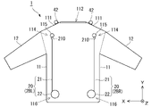
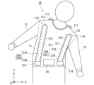
- FIG. 1 is a front view of the protective device 1 according to this embodiment
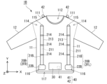
- FIG. 2 is a rear view of the protective device 1 according to this embodiment
- FIG. 3 is a side view of the protective device 1 according to this embodiment. 1 to 3, the vertical direction is indicated as the Y direction, the horizontal direction as the X direction, and the front-back direction as the Z direction.
- left and right mainly indicate left and right when viewed from the user. These directions are shown as an example for convenience of explanation, and the configuration of the protective device 1 is not limited to this. The same applies to subsequent drawings.
- the protection device 1 includes a mounting body 10, an operating section 20, a control section 30, and a sensor 40.
- the wearing body 10 of this embodiment is a jacket type that is worn on the upper half of the body of the user. Note that the wearing body 10 is not limited to a jacket type, and may be worn individually on other parts such as the user's lower body, arms, legs, and head.
- the wearing body 10 has a torso 11 that covers the user's chest and abdomen, and sleeves 12 that cover the arms.
- the body portion 11 is made of a sheet of cloth or synthetic resin and formed into a cylindrical shape.
- a neck hole 112 penetrating vertically is provided between left and right shoulder portions 111 at the upper end of the body portion 11 .
- Armholes 113 for passing the user's arms are provided on the left and right side surfaces of the torso 11 directly below the shoulders 111 .
- the sleeve portion 12 is made of the same material as the body portion 11 and is formed into a cylindrical shape. ing. Note that the sleeve portion 12 may be omitted.
- the user inserts the head, arms, and chest from the opening 117 at the lower end of the wearing body 10, passes the left and right arms through the left and right arm holes 113 into the sleeves 12, and puts out the head from the neck hole 112,
- the torso 11 is worn so as to cover the user's chest and waist.
- the front and rear sides near the left and right shoulders 111 are the moved parts 114, and the connecting part 115 for connecting one end of the operating part 20 is provided at this position.
- a fixed portion 116 is formed at a position spaced apart in the movement direction (Y direction) from each of the moved portions 114, which is near the lower end of the mounting body 10 in this example, and the other end of the operating portion 20 is connected.
- the fixing part 116 is positioned near the waist when the user wears the wearing body 10, and the fixing part 116 is kept in position by fitting the wearing body 10 to the user's body. Further, the position of the fixed part 116 may be maintained by connecting the fixed part 116 and the lower end of the wearing body 10 to the user's trousers or belt.
- the operating section 20 includes, for example, a telescopic structure that can be extended and retracted in one direction, and a drive source that extends and retracts the telescopic structure.
- a wire 21 is provided as an elastic structure, and an electric reel 22 for winding the wire 21 is provided as a drive source.
- a connection portion 210 such as a hook or a carabiner is provided at the tip of the wire 21. By hooking the hook or the carabiner to a ring or the like which is the connection portion 115 of the mounting body, the tip of the wire 21 can be moved by the mounting body 10. It is connected to point 114 .
- the reel 22 is provided on the fixed portion 116 near the lower end of the mounting body 10 , and its rotation is controlled by the control portion 30 .
- the reel 22 winds the wire 21 to shorten the distance from the reel 22 to the tip of the wire 21. ⁇ Further, the reel 22 extends the distance from the reel 22 to the tip of the wire 21 by letting out the wire 21 .
- the working portions 20 are provided at four locations on the left and right front sides and the left and right rear sides of the mounting body 10.
- the left front working part is denoted by 2FL
- the right front working part is denoted by 2FR
- the left rear working part is denoted by 2BL
- the right rear working part is denoted by 2BR.
- the sensor 40 is means for detecting the state of the user or the state of the surroundings of the user. Ranging), three-dimensional scanners and other sensing means.
- the sensor 40 may detect a change in the user's state, such as when the user falls or collides with another object, or may predict that the user will receive an impact. Further, the sensor 40 may not only be worn by the user, but may be sensors that are present around the user and transmit signals to the control unit 30 by wireless communication. Moreover, the sensor 40 may detect a change in the state of an object existing around the user, such as an object that approaches the user and is likely to collide with the user, an object that has collided with the user, or the like.
- Positioning devices include, for example, satellite positioning systems such as GPS (Global Positioning System). Radar and LIDAR find the distance to an object existing around the protection device 1 (user) and the moving speed of the object.
- the controller includes an acceleration sensor 41 for detecting the acceleration of the protection device 1, that is, the acceleration of the user wearing the protection device 1.
- the acceleration sensor 41 detects the rate of change in velocity along a predetermined axis (eg, three axes in the XYZ directions) and the direction as the acceleration of each axis.
- the acceleration sensor 41 may be a so-called hexaaxial sensor that also serves as a sensor for detecting angular velocities on these axes.
- a camera 42 is provided as a second sensor on the shoulder 111 of the wearing body 10, photographs the front of the user, and inputs the photographed image to the control unit 30 as information indicating the state of the user's surroundings. do.
- the camera 42 may be a stereo camera capable of photographing the same subject (object) with a pair of imaging units arranged at a predetermined distance (base line length) and detecting the distance to the subject from the parallax. good. Further, the camera 42 may be further provided with one that captures an image behind the user in addition to the area in front of the user and outputs the captured image to the control unit 30 as information indicating the state of the surroundings of the user.
- sensors other than the acceleration sensor 41 and the camera 42 may be further provided.
- the control unit 30 acquires the detection result of the sensor 40, and when the detection result satisfies a predetermined condition, controls the operation unit 20 to move the moving part of the wearing body 10, thereby changing the posture of the user.
- FIG. 4 is a diagram showing the configuration of the control unit 30.
- the control unit 30 includes a processor 31 , a storage unit 32 and an input/output unit 33 .
- the processor 31 comprehensively executes various kinds of arithmetic processing in the control unit 30 .
- the processor 31 is arithmetic processing means such as a CPU (Central Processing Unit), DSP (Digital Signal Processor), or FPGA (Field-Programmable Gate Array).
- the storage unit 32 includes, for example, a main storage unit 321 and an auxiliary storage unit 322.
- the main storage unit 321 includes a main storage unit such as RAM (Random Access Memory) or ROM (Read Only Memory), and information to be arithmetically processed by the processor 31 is developed. Note that the main storage unit 321 may be formed integrally with the processor 31 .
- the auxiliary storage unit 322 is composed of storage media such as volatile memory such as RAM, non-volatile memory such as ROM, EPROM (Erasable Programmable ROM), hard disk drive (HDD), or removable media.
- volatile memory such as RAM
- non-volatile memory such as ROM, EPROM (Erasable Programmable ROM), hard disk drive (HDD), or removable media.
- the removable medium is, for example, a USB (Universal Serial Bus) memory, a memory card, or other recording medium that can be externally attached and that can be read by a computer.
- USB Universal Serial Bus
- the auxiliary storage unit 322 can store an operating system (OS), various programs, various tables, various databases, user data, etc. for executing the operations of the protective device 1 .
- OS operating system
- programs various programs
- tables various tables
- databases various databases
- user data etc. for executing the operations of the protective device 1 .
- the input/output unit 33 is, for example, an interface that inputs information (detection results, etc.) from the sensor 40 and outputs information (control signals, etc.) to the sensor 40 and other devices. Also, the input/output unit 33 may be a communication module for inputting (receiving) information from other devices and outputting (transmitting) information to other devices. Further, the input/output unit 33 may be a user interface for inputting operation information by the user such as an operation button or a touch panel, and outputting (display, sound output, vibration, etc.) to the user through a display, a speaker, a vibrator, or the like. .
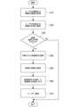
- FIG. 5 is a diagram showing an execution method of the protective device 1 executed by the control unit 30. As shown in FIG. The protective device 1 repeatedly executes the processing of FIG. 5 while the power is ON or when receiving an activation instruction.
- step S10 the control unit 30 acquires state information indicating the state of the user and the state of the surroundings from the sensor 40.
- the control unit 30 acquires the acceleration of the user from the acceleration sensor 41 and detects the captured image of the surroundings from the camera 42 .
- step S20 the control unit 30 analyzes the state of the user and the state of the user's surroundings based on the detection result of the sensor 40 acquired in step S10. For example, based on the acceleration of each axis detected by the acceleration sensor 41, the control unit 30 determines the user's moving direction, moving speed, rate of change in acceleration per unit time (jerk), inclination with respect to the direction of gravity, and the like. request information indicating the status of In addition, the control unit 30 extracts an object existing around the user by image processing the photographed image taken by the camera 42, and obtains the position, moving direction, moving speed, etc. of the object as surrounding information.
- jerk rate of change in acceleration per unit time
- control unit 30 detects the user's motion such as walking, sitting, running, riding a bicycle, or stopping based on the captured image captured by the camera 42. good too.
- a known technique can be used for obtaining the position, speed, moving direction, and the like of an object from the captured image, so detailed description thereof will be omitted.
- the position, speed, and movement direction of an object are not limited to being obtained by the camera 42, but may be acquired by radar, LIDAR, a three-dimensional scanner, or a combination thereof.
- the control unit 30 determines whether or not to operate the protective device 1 depending on whether the information indicating the user's state and the surrounding state obtained at step S20 satisfies a predetermined condition. For example, if the user collides with something or is hit by a vehicle or the like and receives an impact, the impact is detected as a sudden change in acceleration. If the degree exceeds a predetermined threshold, it is determined that the protection device 1 should be operated (positive determination) assuming that the user has received an impact. Further, when the user falls, the user's head (protective device 1) falls at an acceleration close to free fall. If it is hit, it is positively determined that there is a possibility of falling, that is, receiving an impact on the head.
- a predetermined condition For example, if the user collides with something or is hit by a vehicle or the like and receives an impact, the impact is detected as a sudden change in acceleration. If the degree exceeds a predetermined threshold, it is determined that the protection device 1 should be operated (positive determination) assuming that the user has
- the control unit 30 determines that the position of the user after a predetermined time period matches the position of the surrounding object, that is, the object collides with the user. Affirmative determination is made when the probability is high (that is, before the user is impacted). Note that these conditions and thresholds may be settable by a user's operation. Alternatively, when the vehicle or the like is moving toward the user, the affirmative determination may be made when it can be predicted that the collision is unavoidable by considering the speed, acceleration, traveling direction, etc. of the vehicle.
- step S30 the control unit 30 proceeds to step S40 and activates one of the operation units 20 (2FL, 2FR, 2BL, 2BR) attached to the plurality of moving locations 114 of the mounting body 10.
- the operating unit 20 is selected based on the determination result of step S30. For example, if it is determined that the impact will be received from the user's left hand side, the operating parts 2FR and 2BR are selected so that the user's posture is tilted to the opposite right hand side. Further, when the user is in the vehicle, a collision of the vehicle is predicted, and the user is too close to the front airbag device, the operating parts 2BL and 2BR are selected so as to tilt the user backward. .
- step S50 the control unit 30 selects the stage of movement when moving the location to be moved based on the determination result of step S30. For example, when a plurality of positions to be moved are set from the initial position to the movement limit position, the largest movement stage is selected when the shock received is large and the movement is to be made to the movement limit position. Also, when the impact received is moderate and the movement is performed only moderately, the level of moderate movement is selected. It should be noted that the stage of movement may be defined by the movement distance of the location 114 to be moved.
- step S60 the control unit 30 generates a control signal indicating the stage of movement selected in step S50, and transmits it to the operating unit 20 selected in step S40, thereby operating the operating unit 20.
- the sensor 40 detects the amount of movement of the moving part, or the encoder (not shown) provided in the operating part 20 detects the amount of movement of the operating part 20 and feeds it back to the control part 30. Then, feedback control may be performed so that the moved portion is moved by a predetermined amount.
- step S70 the control unit 30 notifies the user (wearer) that the movement of the predetermined amount has been completed through the display, speaker, vibrator, etc. of the input/output unit 33 by sound, light, vibration, or the like.
- the notification to the user is not limited to when the movement is completed, and may be performed at the same time as the operation of the operation unit 20 or before the operation.
- the control unit 30 determines that the distance between the obstacle and the user is within a predetermined range based on the state information
- the control unit 30 issues a warning notification, and when the operation unit 20 is operated, the notification of the operation. may be performed, and a notification of the end of the operation may be given when the movement is completed.
- notification to the user is not limited to these timings, and can be arbitrarily set, including omission.
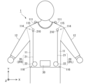
- FIG. 6 is a diagram showing a state before the protective device 1 worn by the user is activated
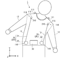
- FIG. 7 is a diagram showing a state after the protective device 1 worn by the user is activated.
- the control unit 30 operates the reels 22 of the operating unit 2FL and the operating unit 2BL to wind the wire 21 and shorten the wire 21.
- the posture of the user is changed so that the upper body of the user is tilted to the left hand side.
- This makes it possible to change the posture so as to avoid a collision with an obstacle that the user does not recognize, thereby protecting the user from unforeseen circumstances.
- the upper body is tilted to the left hand side, but if, for example, an obstacle is predicted to collide with the user's left hand side, the control unit 30 operates the reels 22 of the operating unit 2FR and the operating unit 2BR.
- the user's upper body may be tilted to the right hand side to change the posture by winding the wire 21 and shortening the wire 21 .
- control unit 30 operates the reels 22 of the operation unit 2FL and the operation unit 2FR to shorten the wire 21, thereby changing the user's posture so that the upper body of the user is tilted forward. good too. Further, contrary to FIG. 8, the control unit 30 operates the reels 22 of the operating unit 2BL and the operating unit 2BR to shorten the wire 21, thereby changing the user's posture so as to bend the upper body backward. good too. In this way, the control unit 30 determines the direction in which the impact is received based on the information acquired from the sensor 40, selects the operating unit 20 to be operated accordingly, and adjusts the posture so as to keep the head and heart away from the impact. change the
- control unit may change the degree of movement of the moving part by the operating unit 20 according to the magnitude of the expected impact and the speed of the obstacle. That is, the controller 30 adjusts the distance by which the wire 21 is contracted so that the greater the predicted impact, the larger the movement amount, and the smaller the impact, the smaller the movement amount. For example, when the reel 22 shortens the wire 21 by 200 mm to move the portion 114 to be moved to the movement limit position toward the fixed portion 116, the control unit 30 adjusts the wire 21 to the expected magnitude of impact. Accordingly, it may be adjusted in steps such as 50 mm, 100 mm, 150 mm, and 200 mm.
- control section 30 transmits a control signal to the reel 22 so that the moved portion 114 moves by a target distance from the initial position.
- circuitry may be included to provide feedback to the user that the predetermined distance has been traveled.
- the control signal is not particularly limited as long as it can control the operation of the reel 22, such as the number of pulses, duty ratio, and command.
- the control signal also includes ON/OFF of power supply, such as starting power supply to the reel 22 to be operated and stopping the power supply when the moving part 114 is moved by a predetermined distance.
- the reel 22 rotates freely to some extent so as not to hinder the free movement of the wearer's body when the protective device 1 is not in operation. However, in order to prevent the wire 21 from slackening, the reel 22 is in a state of being biased in the direction in which the wire 21 is drawn.
- the protective device 1 of the present embodiment controls the operating section 20 to move the moved portion 114 of the mounting body 10 by a target distance.
- the protective device 1 of the present embodiment can accurately change the posture by controlling the moving distance of the moved portion 114 as a target value.
- working portions 20 are provided at four locations on the front left and right and rear left and right of the mounting body 10, the working portions 20 are not limited to this, and may be provided at only two locations on the front left and right or only at two locations on the rear left and right. good too.
- FIG. 9 is a diagram showing the configuration of a protection device 1A according to Modification 1.
- the protective device 1A of this modified example differs from the above-described embodiment in the configuration of the working portion 20A. Since other configurations are the same as those of the above-described embodiment, the same elements are denoted by the same reference numerals, and the repetitive description is omitted.
- the operating section 20A of this modification includes a bellows tube 21A as an elastic structure and a pump 22A as a drive source.
- the bellows tube 21A is a cylindrical elastic body having a hollow portion 211 extending in the direction of expansion and contraction, and a peripheral wall 212 defining the hollow portion 211 is formed in a bellows shape.
- the pump 22A extends the bellows tube 21A by supplying air into the hollow portion 211 of the bellows tube 21A and extending the bellows-shaped peripheral wall 212 . Further, the pump 22A shortens the bellows tube 21A by discharging the air from the hollow portion 211 and folding the bellows portion of the peripheral wall 212 .
- FIG. 10 shows an example in which the left front and left rear working portions 20A are shortened and the user's upper body is tilted to the left hand side.
- the control for shortening the left front and left rear working portions 20A is the same as in the above-described embodiment.
- the control unit 30 sends a control signal to the pump 22A so that the pump 22A controls the degree of air supply into the hollow portion 211 of the corrugated tube 21A or the degree of air exhaust from the hollow portion 211.
- the length of the working portion 20A can be adjusted.
- FIG. 11 is a diagram showing the configuration of a protection device 1B according to Modification 2. As shown in FIG. The protective device 1B of this modified example differs from the above-described embodiment in the configuration of the operating portion 20B. Since other configurations are the same as those of the above-described embodiment, the same elements are denoted by the same reference numerals, and the repetitive description is omitted.
- the operating section 20B of this modification includes an elastic tube 21B as an elastic structure and a pump 22B as a drive source.
- the elastic tube 21B is a cylindrical elastic member having a hollow portion 211 extending in the direction of expansion and contraction. It has a straight tubular shape elongated in the stretching direction.
- the elastic tube 21B is provided with a plurality of partitions 214 at predetermined intervals in the direction of expansion and contraction.
- the dividing portion 214 is a metal ring fitted to the outer periphery of the elastic tube 21B, and limits the diameter expansion of the elastic tube 21B.
- the pump 22B supplies air to the inside of the hollow portion 211 to make the inside of the hollow portion 211 a positive pressure, and radially expands the elastic tube 21B at a portion other than the dividing portion 214 .
- the elastic tube 21B is shortened in the expansion/contraction direction.
- FIG. 12 shows an example in which the left front and left rear working portions 20B are shortened and the user's upper body is tilted to the left hand side.
- the control for shortening the left front and left rear working portions 20B is the same as in the above-described embodiment.
- the controller 30 sends a control signal to the pump 22B so that the pump 22B controls the degree of air supply into the hollow portion 211 of the elastic tube 21B, so that the length of the operating portion 20B can be adjusted. can be adjusted.
- FIG. 13 is a diagram showing the configuration of a protection device 1C according to Modification 3. As shown in FIG. 1 C of protection apparatuses of this modification differ in the structure of 20 C of operation parts compared with the above-mentioned embodiment. Since other configurations are the same as those of the above-described embodiment, the same elements are denoted by the same reference numerals, and the repetitive description is omitted.
- the working section 20C of this modified example includes a beam section 215 having one end 2151 connected to the moved portion 114 of the mounting body 10, and a driving section 22C connected to the other end 2152 of the beam section 215. .
- 22 C of drive parts are equipped with the motor 221, the rotating shaft 222, the worm gear 223, and the worm wheel 224.
- the motor 221 is arranged below the mounting body 10 and rotates the rotating shaft 222 according to the control signal from the control section 30 .
- the rotary shaft 222 is connected to the motor 221 and driven to rotate around the Y-axis.
- a worm gear 223 is provided at the upper end of the rotating shaft 222 .
- the worm wheel 224 is rotatably provided on the fixed portion 118 of the mounting body 10 .
- the worm wheel 224 is arranged so that the teeth provided on its outer periphery mesh with the worm gear 223, and is rotated around the Z axis by the rotation of the worm gear 223 around the Y axis.
- the worm wheel 224 of the drive section 22C is connected to the other end 2152 of the beam section 215 and rotates the beam section 215 .
- the control unit 30 operates the operating unit 20C, and the rotation of the motor 221 is transmitted to the beam unit 215 via the rotating shaft 222, the worm gear 223, and the worm wheel 224.
- 2B shows an example in which the end portion 2151 on the side of the moved portion 114 is rotated to the left hand side, and the user's upper body is tilted to the left hand side.
- the control unit 30 can also rotate the end 2151 of the beam unit 215 on the side of the moved part 114 to the right hand side by rotating the motor 221 in the opposite direction to the example of FIG.
- the motor 221 adjusts the amount of rotation in accordance with the control signal from the control section 30, so that the amount of movement of the portion to be moved 114 can be adjusted.
- FIG. 15 is a diagram showing the configuration of a protection device 1D according to Modification 4. As shown in FIG.
- the protective device 1D of this modified example differs from the above-described embodiment in the configuration of the operating portion 20D. Since other configurations are the same as those of the above-described embodiment, the same elements are denoted by the same reference numerals, and the repetitive description is omitted.
- the operating section 20D of this modified example has an electromagnet unit 22D as a drive source and an attraction member 21D that is attracted by the electromagnet unit 22D.
- This modified example is used in a vehicle in which a user rides, and an electromagnet unit 22D as a drive source is provided in the surrounding structure.
- FIG. 15 shows an example in which an electromagnet unit 22D is arranged on the seat 53 next to it.
- the electromagnet unit (driving source) 22D may be provided not only on the seat but also on the A-pillar, B-pillar, C-pillar instrument panel, roof, door trim, etc. of the vehicle.
- the drive source of this modified example is separate from the mounting body 10 and the control unit 30 .
- control unit 30 transmits a control signal to the electromagnet unit 22D via, for example, a wireless communication line to operate the electromagnet unit 22D.
- the controller 30 and the electromagnet unit 22D may be connected by a communication cable, and the control signal may be sent from the controller 30 via the communication cable.
- the installation locations of the electromagnet unit 22D and the attraction member 21D may be interchanged.
- the electromagnet unit 22D has a coil 225 that generates magnetic force, a communication section 226, and a drive circuit 227.
- the communication unit 226 communicates with the control unit 30 and receives control signals.
- the drive circuit 227 supplies power to the coil 225 based on the control signal received by the communication unit 226 to generate magnetic force and function as an electromagnet.
- the drive circuit 227 is connected to, for example, a power line on the vehicle side, acquires power from the vehicle side, and supplies the power to the coil 225 . It should be noted that since power is not supplied to the coil 225 before operation, no magnetic force is generated and the user's side attracting member 21D is not attracted.
- the mounting body 10 of this modified example has the shoulder tip as the moved portion 119, and the suction member 21D is provided at this position.
- the attracting member 21D is a member that is attracted by the magnetic force of the electromagnet unit 22D, and is, for example, a ferromagnetic material or a permanent magnet. Also, the attracting member 21D may be an electromagnet that generates a magnetic force so as to attract the electromagnet unit 22D.
- the control section 30 transmits a control signal to the electromagnet unit 22D of the operation section 20D to generate magnetic force, and moves the attraction member 21D provided at the moved portion 119 of the mounting body 10 toward the electromagnet unit 22D side.
- the user's upper body is tilted to the left hand side by pulling the user. As a result, when an obstacle flies by or when the vehicle is hit by another vehicle, the user's posture can be controlled so as to reduce the impact of the collision.
- the type of vehicle in which the drive source is provided is not particularly limited, and may include buses, trucks, taxis, work vehicles, and the like.
- any vehicle on which the user travels may be used, such as a bicycle, a motorcycle, a ship, an airplane, a kickboard, a train, or a monorail. Further, it may be a roller coaster at an amusement facility, a merry-go-round, a fairy tale cup, a go-kart, or the like.
- FIG. 17 is a diagram showing the configuration of a protection device 1D according to Modification 5. As shown in FIG. The protective device 1D of this modified example differs from that of the fourth modified example in that the drive source is arranged on the ceiling of the vehicle. Since the rest of the configuration is the same as that of Modified Example 4, the same elements are denoted by the same reference numerals, and the repetitive description thereof is omitted.
- the operation part 20D of this modification has an electromagnet unit 22D as a drive source provided on the ceiling 51 of the vehicle, and as shown in FIG. A unit 22D is provided.
- each seat 53 has an electromagnet unit 22D1 on the right rear side, an electromagnet unit 22D2 on the left rear side, an electromagnet unit 22D3 on the left front side, and an electromagnet unit 22D4 on the right front side.
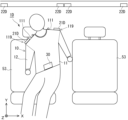
- FIG. 19 shows that the control unit 30 transmits a control signal to the electromagnet unit 22D3 of the operation unit 20D to generate a magnetic force, and moves the attraction member 21D provided at the moved portion 119 of the mounting body 10 to the electromagnet unit 22D3 side.
- the control unit 30 transmits a control signal to the electromagnet unit 22D3 of the operation unit 20D to generate a magnetic force, and moves the attraction member 21D provided at the moved portion 119 of the mounting body 10 to the electromagnet unit 22D3 side.
- the control unit 30 transmits a control signal to the electromagnet unit 22D3 of the operation unit 20D to generate a magnetic force, and moves the attraction member 21D provided at the moved portion 119 of the mounting body 10 to the electromagnet unit 22D3 side.
- FIG. 20 is a diagram showing the configuration of a protection device 1E according to Modification 6. As shown in FIG. The protective device 1E of this modified example differs from that of the fourth modified example in the configuration of the operating part 20 . Since the rest of the configuration is the same as that of Modified Example 4, the same elements are denoted by the same reference numerals, and the repetitive description thereof is omitted.
- the operating section 20E of this modified example includes a wire 21 as an elastic structure and an electric reel unit 22E that winds the wire 21 as a drive source.
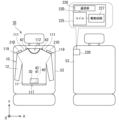
- a reel unit 22E is provided on an instrument panel 52 of the vehicle.
- FIG. 20 shows the user sitting on the front passenger seat in plan view.
- a reel unit 22ER is provided in front of the user's right hand side
- a reel unit 22EL is provided in front of the user's left hand side.
- the reel unit 22E (22ER, 22EL) has an electric reel 228 for winding the wire 21, a communication section 226, and a drive circuit 229.
- the communication unit 226 communicates with the control unit 30 and receives control signals.
- the drive circuit 229 supplies electric power to the reel 228 based on the control signal received by the communication unit 226, thereby causing the wire 21 to be wound or unwound.
- the drive circuit 229 is connected to, for example, a power line on the vehicle side, acquires power from the vehicle side, and supplies it to the reel 228 .
- connection parts 210 such as hooks and carabiners provided at the ends to the ring-shaped connection of the mounting body 10. 115 is connected.
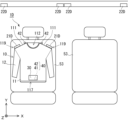
- FIG. 21 shows an example in which the reel unit 22EL is operated to move the user's upper body forward on the left hand side.
- the controller 30 can operate the reel unit 22ER to move the user's upper body forward on the right hand side.
- FIGS. 20 and 21 show an example in which the reel units 22E are provided at two locations on the left and right, the reel units 22E are not limited to this, and may be provided at other locations such as adjacent seats, B-pillars, door trims, and ceilings. It may be configured to move in the direction of .
- FIG. 22 is a diagram showing the configuration of a protection device 1E according to Modification 7. As shown in FIG. The protective device 1E of this modified example differs from that of the sixth modified example in that the reel unit 22E is provided near the steering wheel 54 in front of the driver's seat. Since the rest of the configuration is the same as that of Modified Example 6, the same elements are denoted by the same reference numerals, and the repetitive description thereof is omitted.
- the operating section 20E of this modified example includes a wire 21 as an elastic structure and an electric reel unit 22E that winds the wire 21 as a drive source.
- a reel unit 22E is provided near the steering wheel 54 of the vehicle, for example, on the instrument panel 52.
- FIG. 21 shows the user sitting in the driver's seat in plan view.
- a reel unit 22ER is provided in front of the user's right hand side
- a reel unit 22EL is provided in front of the user's left hand side.
- control unit 30 determines to operate the protective device 1, it transmits a control signal to the reel unit 22E to wind the wire 21 and control the posture of the user.
- FIG. 23 shows an example in which the reel unit 22EL is operated to move the user's upper body forward on the left hand side.
- the controller 30 can operate the reel unit 22ER to move the user's upper body forward on the right hand side.
Landscapes
- Engineering & Computer Science (AREA)
- Health & Medical Sciences (AREA)
- Mechanical Engineering (AREA)
- Robotics (AREA)
- Animal Behavior & Ethology (AREA)
- Life Sciences & Earth Sciences (AREA)
- Rehabilitation Therapy (AREA)
- General Health & Medical Sciences (AREA)
- Public Health (AREA)
- Veterinary Medicine (AREA)
- Physical Education & Sports Medicine (AREA)
- Pain & Pain Management (AREA)
- Epidemiology (AREA)
- Rehabilitation Tools (AREA)
- Manipulator (AREA)
Abstract
保護装置が、ユーザの状態、又は前記ユーザの周囲の状態を示す状態情報を検出するセンサと、前記ユーザの身体に装着される装着体と、前記装着体の少なくとも一部を移動させることにより前記身体の姿勢を変更させる稼働部と、前記稼働部を制御する制御部と、を備え、前記制御部が、前記センサから前記状態情報を取得することと、前記状態情報に基づいて、回避すべき事態が発生したか否かを判定することと、前記回避すべき事態が発生したと判定した場合に、前記稼働部を駆動させて前記装着体の少なくとも一部を移動させることを実行する。これにより、前記保護装置は、ユーザにとって不慮の事態から当該ユーザの身体を保護することができる。
Description
本発明は、保護装置及び保護装置の駆動方法に関する。
特許文献1には、アクチュエータによって伸長または短縮される伝達要素を介して能動的に補助される肢に結合されたアクチュエータを含むウェアラブル能動補助装置が開示されている。
特許文献1の装置は、怪我や病気によって四肢の動きが損なわれている患者に装着され、当該四肢の動きに合わせて、その動きを補助するものである。このため例えば、患者の死角から接近する障害物を避けるなど、患者の意図しない動きが行えるものではなかった。
本開示の技術は、上記した実情に鑑みてなされたものであり、その目的は、ユーザにとって不慮の事態から当該ユーザの身体を保護する技術を提供することにある。
上記課題を解決するために、本開示の保護装置は、
ユーザの状態、又は前記ユーザの周囲の状態を示す状態情報を検出するセンサと、
前記ユーザの身体に装着される装着体と、
前記装着体の少なくとも一部を移動させることにより前記身体の姿勢を変更させる稼働部と、
前記稼働部を制御する制御部と、
を備え、
前記制御部が、
前記センサから前記状態情報を取得することと、
前記状態情報に基づいて、回避すべき事態が発生したか否かを判定することと、
前記回避すべき事態が発生したと判定した場合に、前記稼働部を駆動させて前記装着体の少なくとも一部を移動させることと、
を実行する。
ユーザの状態、又は前記ユーザの周囲の状態を示す状態情報を検出するセンサと、
前記ユーザの身体に装着される装着体と、
前記装着体の少なくとも一部を移動させることにより前記身体の姿勢を変更させる稼働部と、
前記稼働部を制御する制御部と、
を備え、
前記制御部が、
前記センサから前記状態情報を取得することと、
前記状態情報に基づいて、回避すべき事態が発生したか否かを判定することと、
前記回避すべき事態が発生したと判定した場合に、前記稼働部を駆動させて前記装着体の少なくとも一部を移動させることと、
を実行する。
前記保護装置は、前記稼働部が、前記装着体における所定の被移動箇所に取り付けられ、前記被移動箇所を初期位置から所定距離離れた位置へ移動させてもよい。
前記保護装置は、前記稼働部が、前記装着体における所定の被移動箇所に取り付けられ、前記被移動箇所を初期位置から移動限界位置までの間で複数段階の位置へ移動させることが可能であり、
前記制御部が、前記状態情報に基づいて前記稼働部による移動の段階を選択し、選択した段階を示す制御信号を前記稼働部へ送信し、
前記稼働部が、前記制御部から受信した制御信号が示す段階の位置へ前記被移動箇所を移動させても良い。
前記制御部が、前記状態情報に基づいて前記稼働部による移動の段階を選択し、選択した段階を示す制御信号を前記稼働部へ送信し、
前記稼働部が、前記制御部から受信した制御信号が示す段階の位置へ前記被移動箇所を移動させても良い。
前記保護装置は、前記装着体における複数の被移動箇所にそれぞれ前記稼働部が取り付けられ、
前記制御部が、前記状態情報に基づいて、前記複数の被移動箇所に取り付けられた前記稼働部のうち、稼働させる前記稼働部を選択し、選択した前記稼働部に対して制御信号を送信してもよい。
前記制御部が、前記状態情報に基づいて、前記複数の被移動箇所に取り付けられた前記稼働部のうち、稼働させる前記稼働部を選択し、選択した前記稼働部に対して制御信号を送信してもよい。
前記保護装置は、前記稼働部が、一方向に伸縮可能な伸縮構造体と、前記伸縮構造体を伸縮させる駆動源とを備え、前記装着体の前記被移動箇所と、当該被移動箇所から移動方向へ離間した位置に固設された固設部との間に、少なくとも前記伸縮構造体が接続され、前記駆動源によって前記伸縮構造体を縮めることにより前記被移動箇所を前記固設部側へ移動させてもよい。
前記保護装置は、前記伸縮構造体がワイヤーであり、前記駆動源が前記ワイヤーを巻きとるリールであって、前記リールが前記ワイヤーを巻きとることで、前記リールから前記ワイヤー先端までの距離を縮めてもよい。
前記保護装置は、前記伸縮構造体が、伸縮方向に延在する中空部を有し、当該中空部を画する周壁が蛇腹状の弾性体で構成され、
前記駆動源が、ポンプであり、前記中空部内へ空気を供給して蛇腹状の前記周壁を伸ばすことで前記伸縮構造体を伸長させる、又は前記中空部内から空気を排出して蛇腹状の前記周壁を縮ませることで前記伸縮構造体を短縮させてもよい。
前記駆動源が、ポンプであり、前記中空部内へ空気を供給して蛇腹状の前記周壁を伸ばすことで前記伸縮構造体を伸長させる、又は前記中空部内から空気を排出して蛇腹状の前記周壁を縮ませることで前記伸縮構造体を短縮させてもよい。
前記保護装置は、前記伸縮構造体が、伸縮方向に延在する中空部を有し、前記中空部を画する周壁が、中空部内の気圧と中空部外の気圧とが等しい場合に前記伸縮方向において伸長した状態をとる筒状の弾性体であり、
前記駆動源が、ポンプであって、前記中空部内へ空気を供給して前記中空部内を陽圧とし、前記周壁を外側へ湾曲させることで、前記伸縮構造体を前記伸縮方向において短縮させてもよい。
前記駆動源が、ポンプであって、前記中空部内へ空気を供給して前記中空部内を陽圧とし、前記周壁を外側へ湾曲させることで、前記伸縮構造体を前記伸縮方向において短縮させてもよい。
前記保護装置は、前記稼働部が、前記装着体の前記被移動箇所に一端部が接続されたビーム部と、前記ビーム部の他端部に接続された駆動部とを備え、前記駆動部が前記ビーム部の前記他端部付近を中心に前記ビーム部を回転させることで、前記被移動箇所を移動させてもよい。
前記保護装置は、前記稼働部が、前記被移動箇所から移動方向へ離間した位置に配置された電磁石と、
前記装着体の前記被移動箇所に配置され、前記電磁石によって吸引される吸引部材とを備え、前記電磁石が電力の供給を受けて磁力を発生させて前記吸引部材を引き寄せることで前記被移動箇所を移動させてもよい。
前記装着体の前記被移動箇所に配置され、前記電磁石によって吸引される吸引部材とを備え、前記電磁石が電力の供給を受けて磁力を発生させて前記吸引部材を引き寄せることで前記被移動箇所を移動させてもよい。
上記課題を解決するために、本開示係る保護装置の駆動方法は、
センサによって、ユーザの状態、又は前記ユーザの周囲の状態を示す状態情報を検出するステップと、
前記センサから前記状態情報を制御部が取得するステップと、
前記状態情報に基づいて、回避すべき事態が発生したか否かを前記制御部が判定するステップと、
前記回避すべき事態が発生したと前記制御部が判定した場合に、前記ユーザが装着する装着体に取り付けられた稼働部を駆動させて前記装着体の少なくとも一部を移動させるステップと、
を含む。
センサによって、ユーザの状態、又は前記ユーザの周囲の状態を示す状態情報を検出するステップと、
前記センサから前記状態情報を制御部が取得するステップと、
前記状態情報に基づいて、回避すべき事態が発生したか否かを前記制御部が判定するステップと、
前記回避すべき事態が発生したと前記制御部が判定した場合に、前記ユーザが装着する装着体に取り付けられた稼働部を駆動させて前記装着体の少なくとも一部を移動させるステップと、
を含む。
前記保護装置の駆動方法において、前記装着体の少なくとも一部を移動させるステップでは、前記装着体の所定の被移動箇所に取り付けられた前記稼働部により、前記被移動箇所を初期位置から所定距離離れた位置へ移動させるステップを含んでもよい。
前記保護装置の駆動方法において、前記被移動箇所を初期位置から移動限界位置までの間で複数設定された移動の段階から、前記制御部により、前記状態情報に基づいて前記稼働部による移動の段階を選択し、選択した段階を示す制御信号を前記稼働部へ送信するステップと、
前記稼働部により、前記制御部から受信した制御信号が示す段階の位置へ前記被移動箇所を移動させるステップ
を含んでもよい。
前記稼働部により、前記制御部から受信した制御信号が示す段階の位置へ前記被移動箇所を移動させるステップ
を含んでもよい。
前記保護装置の駆動方法において、前記制御部によって、前記装着体における複数の被移動箇所にそれぞれ取り付けられた稼働部のうち前記状態情報に基づいて稼働させる前記稼働部を選択し、選択した前記稼働部に対して制御信号を送信するステップ
を含んでもよい。
を含んでもよい。
本開示によれば、ユーザにとって不慮の事態から当該ユーザの身体を保護する技術を提供できる。
以下に、図面を参照して本開示の実施形態に係る保護装置について説明する。なお、実施形態における各構成及びそれらの組み合わせ等は、一例であって、本開示の主旨から逸脱しない範囲内で、適宜、構成の付加、省略、置換、及びその他の変更が可能である。本開示は、実施形態によって限定されることはなく、特許請求の範囲によってのみ限定される。
<第一実施形態>
図1は、本実施形態に係る保護装置1の正面図、図2は、本実施形態に係る保護装置1の背面図、図3は、本実施形態に係る保護装置1の側面図である。図1~図3では、上下方向をY方向、左右方向をX方向、前後方向をZ方向として示す。なお、以下の説明において、左右は、主にユーザから見た場合の左右を示す。これらの方向は、説明の便宜のため一例として示すものであり、保護装置1の構成をこれに限定するものではない。以降の図面についても同様である。
図1は、本実施形態に係る保護装置1の正面図、図2は、本実施形態に係る保護装置1の背面図、図3は、本実施形態に係る保護装置1の側面図である。図1~図3では、上下方向をY方向、左右方向をX方向、前後方向をZ方向として示す。なお、以下の説明において、左右は、主にユーザから見た場合の左右を示す。これらの方向は、説明の便宜のため一例として示すものであり、保護装置1の構成をこれに限定するものではない。以降の図面についても同様である。
保護装置1は、装着体10と、稼働部20と、制御部30と、センサ40とを備えている。本実施形態の装着体10は、ユーザの上半身に装着されるジャケット型である。なお、装着体10は、ジャケット型に限定されるものではなく、ユーザの下半身や、腕、足、頭部など、他の部位に個別に装着されるものであってもよい。
装着体10は、ユーザの胸部及び腹部などを覆う胴部11と、腕を覆う袖部12とを有している。胴部11は、布や合成樹脂のシートが筒状に成形され、その上側開口における左右の一部が前後に縫い合わされて肩部111が形成されている。胴部11の上端において、左右の肩部111の間には、上下に貫通したネックホール112が設けられている。また、胴部11の左右側面において、肩部111の直下には、ユーザの腕を通すためのアームホール113が設けられている。袖部12は、胴部11と同様の素材で筒状に成形され、肩側(上側)の開口がアームホール113と連通するように、袖部12の一端が胴部11の肩口に縫い付けられている。なお、袖部12は、省略されてもよい。装着体10は、ユーザが下端の開口117から、頭部、腕、及び胸部を入れ、左右の腕を夫々左右のアームホール113から袖部12内に通すと共に、ネックホール112から頭部を出し、胴部11がユーザの胸部から腰付近を覆うように装着される。
本実施形態の装着体10では、左右の肩部111付近における前側及び後側を被移動箇所114とし、この位置に稼働部20の一端を接続するための接続部115が設けられている。また、各被移動箇所114から移動方向(Y方向)に離間した位置、本例では装着体10の下端付近を固設部116とし、稼働部20の他端を接続している。固設部116は、ユーザが装着体10を装着した場合にウェストの付近に位置し、装着体10がユーザの身体にフィットすることで、固設部116の位置が保たれる。また、固設部116や装着体10の下端がユーザのズボンやベルトに連結されることで、固設部116の位置が保たれるように構成されてもよい。
稼働部20は、例えば一方向に伸縮可能な伸縮構造体と、この伸縮構造体を伸縮させる駆動源とを備えている。本実施形態では、伸縮構造体としてワイヤー21を備え、駆動源としてワイヤー21を巻きとる電動のリール22とを備えている。ワイヤー21の先端には例えばフックやカラビナなどの接続部210が設けられ、このフックやカラビナを装着体側の接続部115であるリング等にかけることで、ワイヤー21の先端が装着体10の被移動箇所114に接続される。リール22は、装着体10の下端付近における固設部116に設けられ、制御部30によって、その回転が制御される。リール22が、ワイヤー21を巻き取ることで、リール22からワイヤー21先端までの距離を短縮させる。また、リール22が、ワイヤー21を繰り出すことで、リール22からワイヤー21先端までの距離を伸長させる。つまり本実施形態では稼働部の一部を構成する伸縮構造体として、リール22の巻取りによってワイヤー21の長さが接続部115と固設部116間で変わる例を示している。図1及び図2に示すように、稼働部20は、装着体10の前側左右と後側左右の4カ所に設けられており、これらを総括して説明する場合には、符号20を用い、これらを区別して説明する場合、左前の稼働部に符号2FL、右前の稼働部に符号2FR、左後の稼働部に符号2BL、右後の稼働部に符号2BRを用いて説明する。
センサ40は、ユーザの状態又はユーザの周囲の状態を検出する手段であり、例えば、加速度センサ、ジャイロセンサ(角速度センサ)、測位装置、カメラ、レーダ、LIDAR(Light Detection and Ranging、Laser Imaging Detection and Ranging)、三次元スキャナなどの感知手段を含むものである。センサ40は、ユーザが転倒した場合や、ユーザが他の物体と衝突した場合など、ユーザの状態変化を検出するものや、ユーザが衝撃を受けることを予測するものであってもよい。さらにセンサ40は、ユーザ自身が装着しているものだけでなく、ユーザの周囲に存在するセンサ類から無線通信によって制御部30に信号を送るものであってもよい。また、センサ40は、ユーザに接近し、ユーザに衝突しそうな物体や、衝突した物体など、ユーザの周囲に存在する物体の状態変化を検出するものであってもよい。測位装置としては、例えばGPS(Global Positioning System)等の衛星測位システムが挙げられる。レーダ及びLIDARは、保護装置1(ユーザ)の周囲に存在する物体との距離や、当該物体の移動速度を求める。
本実施形態では、保護装置1の加速度、即ち保護装置1を装着したユーザの加速度を検出する加速度センサ41を制御部内に有している。加速度センサ41は、所定の軸(例えばXYZ方向の三軸)における速度の変化率と、その方向を各軸の加速度として検出する。加速度センサ41は、これらの軸における角速度を検出するセンサを兼ねた所謂六軸センサであってもよい。また、装着体10の肩部111上には、カメラ42が第二のセンサとして備えられ、ユーザの前方を撮影して、その撮影画像をユーザの周囲の状態を示す情報として制御部30へ入力する。なお、カメラ42は、所定の距離(基線長)を隔てて配置した一対の撮像ユニットで同一の被写体(物体)を撮影し、その視差から被写体までの距離等を検出できるステレオカメラであってもよい。また、カメラ42は、ユーザの前方に加え、後方を撮影して、その撮影画像をユーザの周囲の状態を示す情報として制御部30へ出力するものが更に設けられてもよい。このように前後に配置されたカメラ42は、例えば夫々が190度以上の画角で撮影を行うことで、ユーザを中心とした全周囲を撮影する。また、加速度センサ41、カメラ42以外のセンサを更に備えてもよい。
制御部30は、センサ40による検出結果を取得し、検出結果が所定条件を満たした場合に稼働部20を制御して、装着体10の被移動部を移動させることにより、ユーザの姿勢を変更させる。図4は、制御部30の構成を示す図である。制御部30は、プロセッサ31、記憶部32、及び入出力部33を備える。プロセッサ31は、制御部30における各種の演算処理を統括的に実行する。プロセッサ31は、CPU(Central Processing Unit)、DSP(Digital Signal Processor)、又はFPGA(Field-Programmable Gate Array)などの演算処理手段である。
記憶部32は、例えば、主記憶部321と、補助記憶部322を備える。主記憶部321は、RAM(Random Access Memory)又はROM(Read Only Memory)などの主記憶部を備え、例えプロセッサ31で演算処理する情報が展開される。なお、主記憶部321は、プロセッサ31と一体に形成されてもよい。
補助記憶部322は、RAM等の揮発性メモリ、ROM等の不揮発性メモリ、EPROM(Erasable Programmable ROM)、ハードディスクドライブ(HDD、Hard Disk Drive)、又はリムーバブルメディアなどの記憶媒体から構成される。なお、リムーバブルメディアは、例えば、USB(Universal Serial Bus)メモリ、または、メモリカード等、外部から装着可能で、かつコンピュータ読み取り可能な記録媒体である。
補助記憶部322には、保護装置1の動作を実行するための、オペレーティングシステム(Operating System:OS)、各種プログラム、各種テーブル、各種データベース、ユーザデータなどが記憶可能である。
入出力部33は、例えば、センサ40からの情報(検出結果等)の入力、及びセンサ40や他の装置への情報(制御信号等)の出力を行うインターフェイスである。また、入出力部33は、他の装置からの情報の入力(受信)、及び他の装置への情報の出力(送信)を行う通信モジュールであってもよい。更に、入出力部33は、操作ボタンやタッチパネルなどユーザによる操作情報の入力、及びディスプレイやスピーカ、バイブレータなどによるユーザへの出力(表示や音出力、振動等)を行うユーザインターフェイスであってもよい。
≪保護動作≫
図5は、制御部30が実行する保護装置1の実行方法を示す図である。保護装置1は、電源がONとなっている期間、或いは起動の指示を受けた場合に、図5の処理を繰り返し実行する。
図5は、制御部30が実行する保護装置1の実行方法を示す図である。保護装置1は、電源がONとなっている期間、或いは起動の指示を受けた場合に、図5の処理を繰り返し実行する。
ステップS10にて、制御部30は、センサ40からユーザの状態及び周囲の状態を示す状態情報を取得する。例えば、制御部30は、加速度センサ41から、ユーザの加速度を取得すると共に、カメラ42から周囲の撮影画像を検出する。
ステップS20にて、制御部30は、ステップS10で取得したセンサ40の検出結果に基づいて、ユーザの状態及びユーザの周囲の状態を解析する。例えば、制御部30は、加速度センサ41で検出した各軸の加速度に基づいて、ユーザの移動方向、移動速度、単位時間当たりの加速度の変化率(躍度)、及び重力方向に対する傾き等、ユーザの状態を示す情報を求める。また、制御部30は、カメラ42で撮影した撮影画像を画像処理することにより、ユーザの周囲に存在する物体を抽出し、その物体の位置や移動方向、移動速度等を周囲の情報として求める。更に、制御部30は、カメラ42で撮影した撮影画像に基づき、ユーザが歩いている、座っている、走っている、自転車に乗っている、停止している等、ユーザの動作を検出してもよい。なお、撮影画像から、物体の位置や速度、移動方向等を求める手法は、公知の技術を用いることができるので、詳細な説明を省略する。また、物体の位置や速度、移動方向は、カメラ42に限らず、レーダ、LIDAR、三次元スキャナ、又はこれらの組み合わせによって取得されるものであってもよい。
ステップS30にて、制御部30は、ステップS20で求めたユーザの状態及び周囲の状態を示す情報が、所定条件を満たすか否かによって、保護装置1を作動させるか否かを判定する。例えば、ユーザが何かに衝突したり、車両等に衝突されたりして衝撃を受けた場合、この衝撃が加速度の急激な変化として検出されるので、制御部30は、ステップS20で求めた躍度が所定の閾値を超えた場合、ユーザが衝撃を受けたものとして、保護装置1を作動させると判定(肯定判定)する。また、ユーザが転倒すると、ユーザの頭部(保護装置1)が自由落下に近い加速度で落ちるので、制御部30は、所定の閾値を超えた加速度で下方向へ移動したことがステップS20で求められた場合、転倒した、即ち頭部に衝撃を受ける可能性があるものとして肯定判定する。更に、制御部30は、ステップS20で求めた物体の位置や移動方向、移動速度等に基づいて、所定時間後のユーザの位置と周囲の物体位置が一致する、即ち当該物体がユーザに衝突する可能性が高い場合(つまりユーザが衝撃を受ける前)に、肯定判定する。なお、これらの条件や閾値は、ユーザの操作によって設定可能であってもよい。または、車両等がユーザに向かって移動している場合に、車輌の速度や加速度、および走行方向等を加味して、衝突が不可避であると予想できる場合に、肯定判定してもよい。
ステップS30で肯定判定した場合、制御部30は、ステップS40へ移行し、装着体10における複数の被移動箇所114にそれぞれ取り付けられた稼働部20(2FL,2FR,2BL,2BR)のうち稼働させる稼働部20をステップS30の判定結果に基づいて選択する。例えば、ユーザの左手側から衝撃を受けると判定した場合、これと反対側の右手側へユーザの姿勢を傾斜させるように、稼働部2FR,2BRを選択する。また、ユーザが車両に乗車しており、車両の衝突が予測され、且つユーザが前方のエアバック装置に近づきすぎている場合に、ユーザを後傾させるように、稼働部2BL,2BRを選択する。
ステップS50にて、制御部30は、ステップS30の判定結果に基づいて、被移動箇所を移動させる場合の移動の段階を選択する。例えば、被移動箇所を初期位置から移動限界位置までの間で複数設定されている場合、受ける衝撃が大きく、移動限界位置まで移動させる場合に、最も大きな移動の段階を選択する。また、受ける衝撃が中程度であり、中程度だけ移動させる場合に、中程度の移動の段階を選択する。なお、移動の段階は、被移動箇所114の移動距離で規定されてもよい。
ステップS60にて、制御部30は、ステップS50で選択した移動の段階を示す制御信号を生成し、ステップS40で選択した稼働部20へ送信することで、稼働部20を作動させる。また移動部20の作動時に、センサ40によって被移動箇所の移動量を検出し、或は稼働部20に設けたエンコーダ(不図示)により稼働部20の移動量を検出し、制御部30へフィードバックして、被移動箇所が所定量移動するようにフィードバック制御してもよい。
ステップS70にて、制御部30は、入出力部33のディスプレイやスピーカ、バイブレータなどから、所定量の移動が完了したことをユーザ(装着者)に音や光、振動などで通知する。なお、ユーザへの通知は、移動完了時に限らず、稼働部20の作動と同時や、作動前に行われてもよい。例えば、制御部30は、状態情報に基づいて障害物とユーザとの距離が所定範囲内となったと判定したときに警告のための通知を行い、稼働部20を作動させるときに作動を知らせる通知を行い、移動完了時に動作終了を知らせる通知を行ってもよい。なお、ユーザへの通知は、これらのタイミングに限定されるものではなく、省略することも含めて任意に設定され得る。
図6は、ユーザに装着された保護装置1が作動する前の状態を示す図、図7は、ユーザに装着された保護装置1が作動した後の状態を示す図である。図6に示すように、保護装置1が作動する前は、ユーザが直立した状態で、被移動箇所114が初期位置にあり、各稼働部20におけるワイヤー21の長さが等しくなっている。そして、例えばユーザの右手側に障害物の衝突が予測される場合、制御部30は、稼働部2FL及び稼働部2BLのリール22を動作させてワイヤー21を巻き取り、ワイヤー21を短くすることで被移動箇所114を固設部116側に引き寄せることで、ユーザの上体を左手側に倒すように姿勢を変更させる。これによりユーザが認識していない障害物との衝突を避けるように姿勢を変更させ、ユーザを不慮の事態から保護することができる。なお、図7では、上体を左手側へ傾斜させたが、例えばユーザの左手側に障害物の衝突が予測される場合、制御部30は、稼働部2FR及び稼働部2BRのリール22を動作させてワイヤー21を巻き取り、ワイヤー21を短くすることでユーザの上体を右手側に倒すように姿勢を変更させてもよい。また、図8に示すように、制御部30が、稼働部2FL及び稼働部2FRのリール22を動作させてワイヤー21を短くすることでユーザの上体を前側に倒すように姿勢を変更させてもよい。更に、図8とは反対に、制御部30が、稼働部2BL及び稼働部2BRのリール22を動作させてワイヤー21を短くすることでユーザの上体を後ろへ反らすように姿勢を変更させてもよい。このように制御部30は、センサ40から取得した情報に基づき、衝撃を受ける方向を判別し、これに応じて操作させる稼働部20を選択し、この衝撃から頭部や心臓を遠ざけるように姿勢を変更させる。
また、制御部は、予測される衝撃の大きさや、障害物の速度に応じて、稼働部20による被移動箇所の移動の程度を変化させてもよい。即ち、制御部30は予測される衝撃が大きいほど移動量を大きく、当該衝撃が小さいほど移動量を小さくするように、ワイヤー21を縮める距離を調整する。例えば、リール22が、ワイヤー21を200mm短くすることで被移動箇所114を固設部116側へ移動限界位置まで移動させる場合に、制御部30は、ワイヤー21を予測される衝撃の大きさに応じて、50mm、100mm、150mm、200mmのように段階的に調整してもよい。この場合、制御部30は、被移動箇所114が初期位置から目的の距離だけ移動するようにリール22へ制御信号を送信する。その結果、所定距離を移動したことをユーザにフィードバックする回路を含んでいてもよい。なお、制御信号は、特段限定されるものではなく、パルス数や、デューティー比、コマンドなど、リール22の動作を制御できるものであればよい。本実施形態では、動作させるリール22に電力の供給を開始し、被移動箇所114を所定距離移動させた場合に電力供給を停止するといった、電力供給のON/OFFも制御信号に含む。なお、保護装置1は非作動時において装着者の自由な身体の動きを妨げないよう、リール22はある程度自由に回転するようになっている。ただしワイヤー21が弛まないようにするためリール22はワイヤー21を引き込む方向に付勢された状態になっている。
また、このように本実施形態の保護装置1は、稼働部20が、装着体10の被移動箇所114を目的とする距離だけ移動させるように制御する。ユーザの姿勢を変更させる場合に、電流量やトルク量を目的値として制御を行なうと、ユーザの体格によって制御結果が変化してしまい、目的の姿勢とならないことが考えられる。このため本実施形態の保護装置1は、被移動箇所114の移動距離を目的値として制御することで、精度良く姿勢を変更させることができる。
なお、稼働部20は、装着体10の前側左右と後側左右の4カ所に設けられたが、これに限らず、前側左右の2カ所のみ、又は後側左右の2カ所のみに設けられてもよい。
<変形例1>
図9は、変形例1に係る保護装置1Aの構成を示す図である。本変形例の保護装置1Aは、前述の実施形態と比べて、稼働部20Aの構成が異なっている。なお、その他の構成は前述の実施形態と同じであるため、同一の要素には同符号を付すなどして再度の説明を省略する。
図9は、変形例1に係る保護装置1Aの構成を示す図である。本変形例の保護装置1Aは、前述の実施形態と比べて、稼働部20Aの構成が異なっている。なお、その他の構成は前述の実施形態と同じであるため、同一の要素には同符号を付すなどして再度の説明を省略する。
本変形例の稼働部20Aは、伸縮構造体として蛇腹管21Aを備え、駆動源としてポンプ22Aを備えている。蛇腹管21Aは、伸縮方向に延在する中空部211を有する筒状の弾性体であって、中空部211を画する周壁212が蛇腹状に形成されている。ポンプ22Aは、蛇腹管21Aの中空部211内へ空気を供給して蛇腹状の周壁212を伸ばすことで蛇腹管21Aを伸長させる。また、ポンプ22Aは、中空部211内から空気を排出して周壁212の蛇腹部分を畳ませることで、蛇腹管21Aを短縮させる。
図10は、左前及び左後ろの稼働部20Aを短縮させ、ユーザの上体を左手側へ傾斜させた例を示している。左前及び左後ろの稼働部20Aを短縮させる制御は前述の実施形態と同じである。また、本変形例においてもポンプ22Aが、蛇腹管21Aの中空部211内へ給気する程度、又は中空部211から排気する程度を制御するように、制御部30がポンプ22Aへ制御信号を送ることで、稼働部20Aの長さを調整できる。
<変形例2>
図11は、変形例2に係る保護装置1Bの構成を示す図である。本変形例の保護装置1Bは、前述の実施形態と比べて、稼働部20Bの構成が異なっている。なお、その他の構成は前述の実施形態と同じであるため、同一の要素には同符号を付すなどして再度の説明を省略する。
図11は、変形例2に係る保護装置1Bの構成を示す図である。本変形例の保護装置1Bは、前述の実施形態と比べて、稼働部20Bの構成が異なっている。なお、その他の構成は前述の実施形態と同じであるため、同一の要素には同符号を付すなどして再度の説明を省略する。
本変形例の稼働部20Bは、伸縮構造体として弾性管21Bを備え、駆動源としてポンプ22Bを備えている。弾性管21Bは、伸縮方向に延在する中空部211を有した筒状の弾性部材であって、中空部211を画する周壁213が、中空部内の気圧と中空部外の気圧とが等しい場合に前記伸縮方向において伸長した直管状となっている。また、弾性管21Bは、伸縮方向において所定の間隔を空けて複数の区切り部214が設けられている。区切り部214は、弾性管21Bの外周に嵌められた金属のリングであり、弾性管21Bの拡径を制限している。
ポンプ22Bは、中空部211内へ空気を供給して中空部211内を陽圧とし、弾性管21Bを区切り部214以外の部分で径方向へ膨張させる。これにより弾性管21Bの周壁213を外側へ湾曲させることで、弾性管21Bを伸縮方向において短縮させる。
図12は、左前及び左後ろの稼働部20Bを短縮させ、ユーザの上体を左手側へ傾斜させた例を示している。左前及び左後ろの稼働部20Bを短縮させる制御は前述の実施形態と同じである。また、本変形例においてもポンプ22Bが、弾性管21Bの中空部211内へ給気する程度を制御するように、制御部30がポンプ22Bへ制御信号を送ることで、稼働部20Bの長さを調整できる。
<変形例3>
図13は、変形例3に係る保護装置1Cの構成を示す図である。本変形例の保護装置1Cは、前述の実施形態と比べて、稼働部20Cの構成が異なっている。なお、その他の構成は前述の実施形態と同じであるため、同一の要素には同符号を付すなどして再度の説明を省略する。
図13は、変形例3に係る保護装置1Cの構成を示す図である。本変形例の保護装置1Cは、前述の実施形態と比べて、稼働部20Cの構成が異なっている。なお、その他の構成は前述の実施形態と同じであるため、同一の要素には同符号を付すなどして再度の説明を省略する。
本変形例の稼働部20Cは、装着体10の被移動箇所114に一端部2151が接続されたビーム部215と、ビーム部215の他端部2152に接続された駆動部22Cとを備えている。駆動部22Cは、モータ221と、回転軸222、ウォームギヤ223、ウォームホイール224を備えている。モータ221は、装着体10の下部に配置され、制御部30からの制御信号に応じて回転軸222を回転させる。回転軸222は、モータ221と接続され、Y軸周りに回転駆動される。回転軸222の上端にはウォームギヤ223が設けられている。ウォームホイール224は、装着体10の固設部118に回転自在に設けられている。また、ウォームホイール224は、その外周にもうけられた歯がウォームギヤ223と噛み合うように配置され、ウォームギヤ223がY軸回りに回転することにより、Z軸回りに回転させられる。
駆動部22Cのウォームホイール224は、ビーム部215の他端部2152と接続されビーム部215を回転させる。
図14では、制御部30によって稼働部20Cが作動され、モータ221の回転が回転軸222、ウォームギヤ223、及びウォームホイール224を介してビーム部215に伝えられ、ビーム部215の下端部2152を中心に被移動箇所114側端部2151が左手側に回転され、ユーザの上体を左手側へ傾斜させた例を示している。また、制御部30は、図14の例とは逆にモータ221を回転させることで、ビーム部215の被移動箇所114側端部2151を右手側に回転させることもできる。また、本変形例においてもモータ221が制御部30の制御信号に応じて回転量を調整することで、被移動箇所114の移動量を調整できる。
<変形例4>
図15は、変形例4に係る保護装置1Dの構成を示す図である。本変形例の保護装置1Dは、前述の実施形態と比べて、稼働部20Dの構成が異なっている。なお、その他の構成は前述の実施形態と同じであるため、同一の要素には同符号を付すなどして再度の説明を省略する。
図15は、変形例4に係る保護装置1Dの構成を示す図である。本変形例の保護装置1Dは、前述の実施形態と比べて、稼働部20Dの構成が異なっている。なお、その他の構成は前述の実施形態と同じであるため、同一の要素には同符号を付すなどして再度の説明を省略する。
本変形例の稼働部20Dは、駆動源としての電磁石ユニット22Dと、電磁石ユニット22Dによって吸引される吸引部材21Dとを有している。本変形例では、ユーザが乗車した車両内で用いられ、駆動源としての電磁石ユニット22Dが周囲の構造物に設けられている。図15では、隣の座席53に電磁石ユニット22Dが配置されている例を示している。なお、電磁石ユニット(駆動源)22Dは、座席に限らず、車両のAピラー、Bピラー、Cピラーインストルメンタルパネル、ルーフ、ドアトリムなどに設けられてもよい。このように本変形例の駆動源は、装着体10や制御部30と別体となっている。このため、制御部30は、例えば無線通信回線を介して制御信号を電磁石ユニット22Dへ送信し、電磁石ユニット22Dを作動させる。また、ユーザが乗車時に制御部30と電磁石ユニット22Dとを通信ケーブルで接続し、制御部30から通信ケーブルを介して制御信号を送るようにしてもよい。また電磁石ユニット22Dと吸引部材21Dの設置場所を入れ替えてもよい。
電磁石ユニット22Dは、磁力を発生させるコイル225、通信部226、駆動回路227を有している。通信部226は、制御部30と通信し制御信号を受信する。駆動回路227は、通信部226で受信した制御信号に基づいてコイル225に電力を供給して磁力を発生させ、電磁石として機能させる。駆動回路227は、例えば車両側の電力ラインと接続し、車両側から電力を取得してコイル225へ供給する。なお、作動前は、コイル225に電力を供給していないので、磁力を発生させず、ユーザ側の吸引部材21Dを吸引しない。
また、本変形例の装着体10は、肩先を被移動箇所119とし、この位置に吸引部材21Dが設けられている。吸引部材21Dは、電磁石ユニット22Dの磁力によって吸引される部材であり、例えば強磁性体や永久磁石である。また、吸引部材21Dは、電磁石ユニット22Dと引き合うように磁力を発生させる電磁石であってもよい。
図16では、制御部30が、稼働部20Dの電磁石ユニット22Dへ制御信号を送信して磁力を発生させ、装着体10の被移動箇所119に設けられている吸引部材21Dを電磁石ユニット22D側へ引き寄せることで、ユーザの上体を左手側に傾斜させている。これにより障害物が飛翔してきた場合や、他の車輛による衝突を受けた場合に、この衝突の影響を抑えるようにユーザの姿勢を制御することができる。
なお、本変形例では、稼働部20Dの駆動源を車両に設けた例を示したが、駆動源を設ける車両の種類は、特段限定されるものではなく、バス、トラック、タクシー、作業車両等であってもよい。また、ユーザが乗って移動する乗物であればよく、例えば、自転車、自動二輪、船舶、飛行機、キックボード、電車、モノレールであってもよい。更に、アミューズメント施設のジェットコースターや、メリーゴーランド、メルヘンカップ、ゴーカート等であってもよい。
<変形例5>
図17は、変形例5に係る保護装置1Dの構成を示す図である。本変形例の保護装置1Dは、前述の変形例4と比べて、駆動源を車両の天井に配置した構成が異なっている。なお、その他の構成は前述の変形例4と同じであるため、同一の要素には同符号を付すなどして再度の説明を省略する。
図17は、変形例5に係る保護装置1Dの構成を示す図である。本変形例の保護装置1Dは、前述の変形例4と比べて、駆動源を車両の天井に配置した構成が異なっている。なお、その他の構成は前述の変形例4と同じであるため、同一の要素には同符号を付すなどして再度の説明を省略する。
本変形例の稼働部20Dは、駆動源としての電磁石ユニット22Dを車両の天井51に設け、且つ図18に示すように平面視においてユーザが座る各座席53の周囲を囲むように4カ所ずつ電磁石ユニット22Dが設けられている。図18の例では、各座席53の右後側に電磁石ユニット22D1、左後側に電磁石ユニット22D2、左前側に電磁石ユニット22D3、右前側に電磁石ユニット22D4が設けられている。
図19は、制御部30が、稼働部20Dの電磁石ユニット22D3へ制御信号を送信して磁力を発生させ、装着体10の被移動箇所119に設けられている吸引部材21Dを電磁石ユニット22D3側へ引き寄せることで、ユーザの上体を左手側前方に傾斜させている。この場合、ユーザの左肩に位置する吸引部材21Dの極性と、電磁石ユニット22D3の極性を異ならせることで、吸引部材21Dを電磁石ユニット22D3側へ引き寄せている。ここで、移動方向と反対側の電磁石ユニット22D1,22D4の極性と、ユーザの右肩に位置する吸引部材21Dの極性とを同一にすることで、斥力を働かせ、左手側への傾斜を助長するように構成してもよい。また、制御部30は、これらと左右対称に電磁石ユニット22Dを作動させることで、ユーザを右手側前方へ傾斜させることができる。同様に、制御部30は、電磁石ユニット22D1,22D2を作動させることで、ユーザを右手側後方、又は左手側後方へ傾斜させることができる。このように本変形例によれば、制御部30が、電磁石ユニット22D1~22D4のうち、どの電磁石ユニット22Dにどれだけの電流を流すのかを制御することにより、ユーザの姿勢を前後左右へ任意に調整できる。
<変形例6>
図20は、変形例6に係る保護装置1Eの構成を示す図である。本変形例の保護装置1Eは、前述の変形例4と比べて、稼働部20の構成が異なっている。なお、その他の構成は前述の変形例4と同じであるため、同一の要素には同符号を付すなどして再度の説明を省略する。
図20は、変形例6に係る保護装置1Eの構成を示す図である。本変形例の保護装置1Eは、前述の変形例4と比べて、稼働部20の構成が異なっている。なお、その他の構成は前述の変形例4と同じであるため、同一の要素には同符号を付すなどして再度の説明を省略する。
本変形例の稼働部20Eは、伸縮構造体としてワイヤー21を備え、駆動源としてワイヤー21を巻きとる電動のリールユニット22Eとを備えている。そしてリールユニット22Eが車両のインストルメンタルパネル52に設けられている。図20では、助手席に座るユーザを平面視して示している。本変形例では、ユーザの右手側前方にリールユニット22ERが設けられ、ユーザの左手側前方にリールユニット22ELが設けられている。リールユニット22E(22ER,22EL)は、ワイヤー21を巻き取る電動のリール228、通信部226、駆動回路229を有している。通信部226は、制御部30と通信し制御信号を受信する。駆動回路229は、通信部226で受信した制御信号に基づいてリール228に電力を供給することにより、ワイヤー21の巻き取り又は繰り出しを行わせる。駆動回路229は、例えば車両側の電力ラインと接続し、車両側から電力を取得してリール228へ供給する。
ユーザは、車両に乗車した際、これらリールユニット22E(22ER,22EL)からワイヤー21の先端を引き出し、この先端に設けられているフックやカラビナなどの接続部210を装着体10におけるリング状の接続部115と接続させる。
そして制御部30が保護装置1を作動させると判定した場合、リールユニット22Eに制御信号を送信し、ワイヤー21を巻き取らせてユーザの姿勢を制御する。図21は、リールユニット22ELを作動させてユーザの上体を左手側前方に移動させた例を示している。同様に、制御部30は、リールユニット22ERを作動させてユーザの上体を右手側前方に移動させることもできる。なお、図20、図21では、リールユニット22Eを左右二か所に設けた例を示したが、これに限らず隣接するシートや、Bピラー、ドアトリム、天井など、他の箇所に設け、これらの方向へ移動させる構成としてもよい。
<変形例7>
図22は、変形例7に係る保護装置1Eの構成を示す図である。本変形例の保護装置1Eは、前述の変形例6と比べて、リールユニット22Eを運転席前方のハンドル54付近に設けた構成が異なっている。なお、その他の構成は前述の変形例6と同じであるため、同一の要素には同符号を付すなどして再度の説明を省略する。
図22は、変形例7に係る保護装置1Eの構成を示す図である。本変形例の保護装置1Eは、前述の変形例6と比べて、リールユニット22Eを運転席前方のハンドル54付近に設けた構成が異なっている。なお、その他の構成は前述の変形例6と同じであるため、同一の要素には同符号を付すなどして再度の説明を省略する。
本変形例の稼働部20Eは、伸縮構造体としてワイヤー21を備え、駆動源としてワイヤー21を巻きとる電動のリールユニット22Eとを備えている。そしてリールユニット22Eが車両のハンドル54付近、例えばインストルメンタルパネル52に設けられている。図21では、運転席に座るユーザを平面視して示している。本変形例では、ユーザの右手側前方にリールユニット22ERが設けられ、ユーザの左手側前方にリールユニット22ELが設けられている。
制御部30は保護装置1を作動させると判定した場合、リールユニット22Eに制御信号を送信し、ワイヤー21を巻き取らせてユーザの姿勢を制御する。図23は、リールユニット22ELを作動させてユーザの上体を左手側前方に移動させた例を示している。同様に、制御部30は、リールユニット22ERを作動させてユーザの上体を右手側前方に移動させることもできる。
以上、本開示に係る電気回路遮断装置の実施形態について説明したが、本明細書に開示された各々の態様は、本明細書に開示された他のいかなる特徴とも組み合わせることができる。
1,1A,1B,1C,1D,1E 保護装置
10 装着体
11 胴部
12 袖部
20,20A,20B,20C,20D,20E 稼働部
21 ワイヤー
21A 蛇腹管
21B 弾性管
21D 吸引部材
22 リール
22A,22B ポンプ
22C 駆動部
22D 電磁石ユニット(駆動源)
22D1 電磁石ユニット
22E リールユニット
30 制御部
31 プロセッサ
32 記憶部
33 入出力部
40 センサ
111 肩部
112 ネックホール
113 アームホール
114 被移動箇所
115 接続部
116 固設部
116 固定部
117 開口
118 固設部
119 被移動箇所
211 接続部
10 装着体
11 胴部
12 袖部
20,20A,20B,20C,20D,20E 稼働部
21 ワイヤー
21A 蛇腹管
21B 弾性管
21D 吸引部材
22 リール
22A,22B ポンプ
22C 駆動部
22D 電磁石ユニット(駆動源)
22D1 電磁石ユニット
22E リールユニット
30 制御部
31 プロセッサ
32 記憶部
33 入出力部
40 センサ
111 肩部
112 ネックホール
113 アームホール
114 被移動箇所
115 接続部
116 固設部
116 固定部
117 開口
118 固設部
119 被移動箇所
211 接続部
Claims (14)
- ユーザの状態、又は前記ユーザの周囲の状態を示す状態情報を検出するセンサと、
前記ユーザの身体に装着される装着体と、
前記装着体の少なくとも一部を移動させることにより前記身体の姿勢を変更させる稼働部と、
前記稼働部を制御する制御部と、
を備え、
前記制御部が、
前記センサから前記状態情報を取得することと、
前記状態情報に基づいて、回避すべき事態が発生したか否かを判定することと、
前記回避すべき事態が発生したと判定した場合に、前記稼働部を駆動させて前記装着体の少なくとも一部を移動させることと、
を実行する、保護装置。 - 前記稼働部が、前記装着体における所定の被移動箇所に取り付けられ、前記被移動箇所を初期位置から所定距離離れた位置へ移動させる、請求項1に記載の保護装置。
- 前記稼働部が、前記装着体における所定の被移動箇所に取り付けられ、前記被移動箇所を初期位置から移動限界位置までの間で複数段階の位置へ移動させることが可能であり、
前記制御部が、前記状態情報に基づいて前記稼働部による移動の段階を選択し、選択した段階を示す制御信号を前記稼働部へ送信し、
前記稼働部が、前記制御部から受信した制御信号が示す段階の位置へ前記被移動箇所を移動させる、請求項1又は2に記載の保護装置。 - 前記装着体における複数の被移動箇所にそれぞれ前記稼働部が取り付けられ、
前記制御部が、前記状態情報に基づいて、前記複数の被移動箇所に取り付けられた前記稼働部のうち、稼働させる前記稼働部を選択し、選択した前記稼働部に対して制御信号を送信する、請求項1~3の何れか一項に記載の保護装置。 - 前記稼働部が、一方向に伸縮可能な伸縮構造体と、前記伸縮構造体を伸縮させる駆動源とを備え、前記装着体の前記被移動箇所と、当該被移動箇所から移動方向へ離間した位置に固設された固設部との間に、少なくとも前記伸縮構造体が接続され、前記駆動源によって前記伸縮構造体を縮めることにより前記被移動箇所を前記固設部側へ移動させる、請求項2~4の何れか一項に記載の保護装置。
- 前記伸縮構造体がワイヤーであり、前記駆動源が前記ワイヤーを巻きとるリールであって、前記リールが前記ワイヤーを巻きとることで、前記リールから前記ワイヤー先端までの距離を縮める、請求項5に記載の保護装置。
- 前記伸縮構造体が、伸縮方向に延在する中空部を有し、当該中空部を画する周壁が蛇腹状の弾性体で構成され、
前記駆動源が、ポンプであり、前記中空部内へ空気を供給して蛇腹状の前記周壁を伸ばすことで前記伸縮構造体を伸長させる、又は前記中空部内から空気を排出して蛇腹状の前記周壁を縮ませることで前記伸縮構造体を短縮させる、請求項5に記載の保護装置。 - 前記伸縮構造体が、伸縮方向に延在する中空部を有し、前記中空部を画する周壁が、中空部内の気圧と中空部外の気圧とが等しい場合に前記伸縮方向において伸長した状態をとる筒状の弾性体であり、
前記駆動源が、ポンプであって、前記中空部内へ空気を供給して前記中空部内を陽圧とし、前記周壁を外側へ湾曲させることで、前記伸縮構造体を前記伸縮方向において短縮させる、請求項5に記載の保護装置。 - 前記稼働部が、前記装着体の前記被移動箇所に一端部が接続されたビーム部と、前記ビーム部の他端部に接続された駆動部とを備え、前記駆動部が前記ビーム部の前記他端部付近を中心に前記ビーム部を回転させることで、前記被移動箇所を移動させる、請求項2~4の何れか一項に記載の保護装置。
- 前記稼働部が、前記被移動箇所から移動方向へ離間した位置に配置された電磁石と、
前記装着体の前記被移動箇所に配置され、前記電磁石によって吸引される吸引部材とを備え、前記電磁石が電力の供給を受けて磁力を発生させて前記吸引部材を引き寄せることで前記被移動箇所を移動させる、請求項2~4の何れか一項に記載の保護装置。 - センサによって、ユーザの状態、又は前記ユーザの周囲の状態を示す状態情報を検出するステップと、
前記センサから前記状態情報を制御部が取得するステップと、
前記状態情報に基づいて、回避すべき事態が発生したか否かを前記制御部が判定するステップと、
前記回避すべき事態が発生したと前記制御部が判定した場合に、前記ユーザが装着する装着体に取り付けられた稼働部を駆動させて前記装着体の少なくとも一部を移動させるステップと、
を含む、保護装置の駆動方法。 - 前記装着体の少なくとも一部を移動させるステップでは、前記装着体の所定の被移動箇所に取り付けられた前記稼働部により、前記被移動箇所を初期位置から所定距離離れた位置へ移動させるステップを含む、請求項11に記載の保護装置の駆動方法。
- 前記被移動箇所を初期位置から移動限界位置までの間で複数設定された移動の段階から、前記制御部により、前記状態情報に基づいて前記稼働部による移動の段階を選択し、選択した段階を示す制御信号を前記稼働部へ送信するステップと、
前記稼働部により、前記制御部から受信した制御信号が示す段階の位置へ前記被移動箇所を移動させるステップ
を含む、請求項12に記載の保護装置の駆動方法。 - 前記制御部によって、前記装着体における複数の被移動箇所にそれぞれ取り付けられた稼働部のうち前記状態情報に基づいて稼働させる前記稼働部を選択し、選択した前記稼働部に対して制御信号を送信するステップ
を含む、請求項11~13の何れか一項に記載の保護装置の駆動方法。
Applications Claiming Priority (2)
| Application Number | Priority Date | Filing Date | Title |
|---|---|---|---|
| JP2021-131246 | 2021-08-11 | ||
| JP2021131246A JP2023025849A (ja) | 2021-08-11 | 2021-08-11 | 保護装置及び保護装置の駆動方法 |
Publications (1)
| Publication Number | Publication Date |
|---|---|
| WO2023017653A1 true WO2023017653A1 (ja) | 2023-02-16 |
Family
ID=85199737
Family Applications (1)
| Application Number | Title | Priority Date | Filing Date |
|---|---|---|---|
| PCT/JP2022/015800 Ceased WO2023017653A1 (ja) | 2021-08-11 | 2022-03-30 | 保護装置及び保護装置の駆動方法 |
Country Status (2)
| Country | Link |
|---|---|
| JP (1) | JP2023025849A (ja) |
| WO (1) | WO2023017653A1 (ja) |
Citations (5)
| Publication number | Priority date | Publication date | Assignee | Title |
|---|---|---|---|---|
| US20060260027A1 (en) * | 2005-05-23 | 2006-11-23 | Rhodes Carrol L | Head and neck restraint system |
| US20100204628A1 (en) * | 2009-02-06 | 2010-08-12 | Jamshid Ghajar | Apparatus and Methods for Reducing Brain and Cervical Spine Injury |
| US20150157080A1 (en) * | 2013-12-11 | 2015-06-11 | Board Of Trustees Of The Leland Stanford Junior University | Device to reduce head injury risk |
| US20150164171A1 (en) * | 2013-12-18 | 2015-06-18 | Konstantinos Margetis | System and Method for Head and Spine Immobilization and Protection |
| CN209420982U (zh) * | 2018-11-29 | 2019-09-24 | 大连宏洋服装有限公司 | 一种防止磕碰的缓冲童装 |
-
2021
- 2021-08-11 JP JP2021131246A patent/JP2023025849A/ja active Pending
-
2022
- 2022-03-30 WO PCT/JP2022/015800 patent/WO2023017653A1/ja not_active Ceased
Patent Citations (5)
| Publication number | Priority date | Publication date | Assignee | Title |
|---|---|---|---|---|
| US20060260027A1 (en) * | 2005-05-23 | 2006-11-23 | Rhodes Carrol L | Head and neck restraint system |
| US20100204628A1 (en) * | 2009-02-06 | 2010-08-12 | Jamshid Ghajar | Apparatus and Methods for Reducing Brain and Cervical Spine Injury |
| US20150157080A1 (en) * | 2013-12-11 | 2015-06-11 | Board Of Trustees Of The Leland Stanford Junior University | Device to reduce head injury risk |
| US20150164171A1 (en) * | 2013-12-18 | 2015-06-18 | Konstantinos Margetis | System and Method for Head and Spine Immobilization and Protection |
| CN209420982U (zh) * | 2018-11-29 | 2019-09-24 | 大连宏洋服装有限公司 | 一种防止磕碰的缓冲童装 |
Also Published As
| Publication number | Publication date |
|---|---|
| JP2023025849A (ja) | 2023-02-24 |
Similar Documents
| Publication | Publication Date | Title |
|---|---|---|
| US11541781B2 (en) | Methods and devices for vehicle safety mechanisms | |
| JP6710372B2 (ja) | 制限範囲内飛行装置 | |
| JP6123032B2 (ja) | 支援された離陸 | |
| US11007914B2 (en) | Vehicle occupant protection device | |
| US20150206439A1 (en) | Ground vehicle warning to indicate presence of an obstacle near an aircraft | |
| JP2017509330A (ja) | ペットを散歩させるためのシステム及び方法 | |
| JP6831274B2 (ja) | 飛行装置 | |
| CN115520135A (zh) | 车辆侧面气囊 | |
| JP7023492B2 (ja) | 移動体の追従画像提示システム | |
| WO2018109903A1 (ja) | 飛行制御方法、無人航空機、飛行システム、プログラム、及び記録媒体 | |
| WO2018167945A1 (ja) | 乗員保護装置 | |
| JP6948360B2 (ja) | スクーター | |
| CN106515579A (zh) | 车辆的盲点区域监控 | |
| CN113924249B (zh) | 无人飞行体以及信息处理方法 | |
| JP2006015436A (ja) | 監視ロボット | |
| JP6729332B2 (ja) | 障害物検出装置 | |
| JP2021182278A (ja) | 車両の周辺監視システム | |
| JP2012096687A (ja) | 車室内カメラ装置 | |
| JP2020175890A (ja) | 作業車 | |
| WO2023017653A1 (ja) | 保護装置及び保護装置の駆動方法 | |
| US20210076642A1 (en) | Training apparatus | |
| JP2023107927A (ja) | 乗物用シート | |
| KR20200071968A (ko) | 차량 및 그 제어방법 | |
| JP7532893B2 (ja) | 車両の周辺監視システム | |
| WO2024034419A1 (ja) | 保護装置及び保護方法 |
Legal Events
| Date | Code | Title | Description |
|---|---|---|---|
| 121 | Ep: the epo has been informed by wipo that ep was designated in this application |
Ref document number: 22855719 Country of ref document: EP Kind code of ref document: A1 |
|
| NENP | Non-entry into the national phase |
Ref country code: DE |
|
| 122 | Ep: pct application non-entry in european phase |
Ref document number: 22855719 Country of ref document: EP Kind code of ref document: A1 |