WO2023014157A1 - Method for operating remote ue related to path switching and measurement reporting in wireless communication system - Google Patents
Method for operating remote ue related to path switching and measurement reporting in wireless communication system Download PDFInfo
- Publication number
- WO2023014157A1 WO2023014157A1 PCT/KR2022/011642 KR2022011642W WO2023014157A1 WO 2023014157 A1 WO2023014157 A1 WO 2023014157A1 KR 2022011642 W KR2022011642 W KR 2022011642W WO 2023014157 A1 WO2023014157 A1 WO 2023014157A1
- Authority
- WO
- WIPO (PCT)
- Prior art keywords
- remote
- base station
- relay
- measurement report
- information
- Prior art date
Links
- 238000004891 communication Methods 0.000 title claims abstract description 106
- 238000000034 method Methods 0.000 title claims abstract description 88
- 238000005259 measurement Methods 0.000 title claims abstract description 79
- 230000009471 action Effects 0.000 claims description 3
- 239000010410 layer Substances 0.000 description 56
- 230000005540 biological transmission Effects 0.000 description 44
- 230000015654 memory Effects 0.000 description 42
- 230000006870 function Effects 0.000 description 29
- 238000005516 engineering process Methods 0.000 description 23
- 238000013473 artificial intelligence Methods 0.000 description 22
- 230000001360 synchronised effect Effects 0.000 description 22
- 230000008569 process Effects 0.000 description 12
- 238000010295 mobile communication Methods 0.000 description 9
- 238000012545 processing Methods 0.000 description 9
- 238000013468 resource allocation Methods 0.000 description 9
- 238000007726 management method Methods 0.000 description 8
- 230000003190 augmentative effect Effects 0.000 description 7
- 238000010586 diagram Methods 0.000 description 7
- 108091005487 SCARB1 Proteins 0.000 description 5
- 102100037118 Scavenger receptor class B member 1 Human genes 0.000 description 5
- 230000000737 periodic effect Effects 0.000 description 5
- 230000001133 acceleration Effects 0.000 description 4
- 230000008901 benefit Effects 0.000 description 3
- 239000000969 carrier Substances 0.000 description 3
- 230000007774 longterm Effects 0.000 description 3
- 238000013507 mapping Methods 0.000 description 3
- 230000003287 optical effect Effects 0.000 description 3
- 238000003860 storage Methods 0.000 description 3
- 238000012384 transportation and delivery Methods 0.000 description 3
- 102100022734 Acyl carrier protein, mitochondrial Human genes 0.000 description 2
- 101000678845 Homo sapiens Acyl carrier protein, mitochondrial Proteins 0.000 description 2
- 101001055444 Homo sapiens Mediator of RNA polymerase II transcription subunit 20 Proteins 0.000 description 2
- 102100026165 Mediator of RNA polymerase II transcription subunit 20 Human genes 0.000 description 2
- 230000005856 abnormality Effects 0.000 description 2
- 238000013461 design Methods 0.000 description 2
- 238000001514 detection method Methods 0.000 description 2
- 238000009826 distribution Methods 0.000 description 2
- 239000000446 fuel Substances 0.000 description 2
- 230000036541 health Effects 0.000 description 2
- 230000002452 interceptive effect Effects 0.000 description 2
- 238000000638 solvent extraction Methods 0.000 description 2
- 230000002123 temporal effect Effects 0.000 description 2
- 238000012546 transfer Methods 0.000 description 2
- 238000005406 washing Methods 0.000 description 2
- 101000741965 Homo sapiens Inactive tyrosine-protein kinase PRAG1 Proteins 0.000 description 1
- 102100038659 Inactive tyrosine-protein kinase PRAG1 Human genes 0.000 description 1
- 230000004913 activation Effects 0.000 description 1
- 230000003044 adaptive effect Effects 0.000 description 1
- 238000004873 anchoring Methods 0.000 description 1
- 238000003491 array Methods 0.000 description 1
- 238000013528 artificial neural network Methods 0.000 description 1
- 230000004888 barrier function Effects 0.000 description 1
- 230000006399 behavior Effects 0.000 description 1
- 230000036772 blood pressure Effects 0.000 description 1
- 230000015556 catabolic process Effects 0.000 description 1
- 230000001413 cellular effect Effects 0.000 description 1
- 230000008859 change Effects 0.000 description 1
- 238000006243 chemical reaction Methods 0.000 description 1
- 230000000295 complement effect Effects 0.000 description 1
- 230000006835 compression Effects 0.000 description 1
- 238000007906 compression Methods 0.000 description 1
- 238000012937 correction Methods 0.000 description 1
- 125000004122 cyclic group Chemical group 0.000 description 1
- 238000007405 data analysis Methods 0.000 description 1
- 230000000694 effects Effects 0.000 description 1
- 230000005611 electricity Effects 0.000 description 1
- 230000007613 environmental effect Effects 0.000 description 1
- 238000011156 evaluation Methods 0.000 description 1
- 238000010438 heat treatment Methods 0.000 description 1
- 239000002346 layers by function Substances 0.000 description 1
- 238000010801 machine learning Methods 0.000 description 1
- 238000012423 maintenance Methods 0.000 description 1
- 238000004519 manufacturing process Methods 0.000 description 1
- 239000000203 mixture Substances 0.000 description 1
- 238000012544 monitoring process Methods 0.000 description 1
- 238000005457 optimization Methods 0.000 description 1
- 230000004044 response Effects 0.000 description 1
- 230000002441 reversible effect Effects 0.000 description 1
- 230000011218 segmentation Effects 0.000 description 1
- 238000010187 selection method Methods 0.000 description 1
- 230000011664 signaling Effects 0.000 description 1
- 239000010454 slate Substances 0.000 description 1
- 239000004984 smart glass Substances 0.000 description 1
- 238000001228 spectrum Methods 0.000 description 1
- 230000005477 standard model Effects 0.000 description 1
- 230000003068 static effect Effects 0.000 description 1
- 208000037918 transfusion-transmitted disease Diseases 0.000 description 1
- 230000001960 triggered effect Effects 0.000 description 1
Images


Classifications
-
- H—ELECTRICITY
- H04—ELECTRIC COMMUNICATION TECHNIQUE
- H04W—WIRELESS COMMUNICATION NETWORKS
- H04W24/00—Supervisory, monitoring or testing arrangements
- H04W24/10—Scheduling measurement reports ; Arrangements for measurement reports
-
- H—ELECTRICITY
- H04—ELECTRIC COMMUNICATION TECHNIQUE
- H04W—WIRELESS COMMUNICATION NETWORKS
- H04W36/00—Hand-off or reselection arrangements
-
- H—ELECTRICITY
- H04—ELECTRIC COMMUNICATION TECHNIQUE
- H04W—WIRELESS COMMUNICATION NETWORKS
- H04W76/00—Connection management
- H04W76/10—Connection setup
- H04W76/14—Direct-mode setup
-
- H—ELECTRICITY
- H04—ELECTRIC COMMUNICATION TECHNIQUE
- H04W—WIRELESS COMMUNICATION NETWORKS
- H04W76/00—Connection management
- H04W76/20—Manipulation of established connections
- H04W76/23—Manipulation of direct-mode connections
Definitions
- the following description is for a wireless communication system, and more specifically, a method and apparatus related to path switching and measurement reporting of a remote UE in a sidelink relay.
- a wireless communication system is widely deployed to provide various types of communication services such as voice and data.
- a wireless communication system is a multiple access system capable of supporting communication with multiple users by sharing available system resources (bandwidth, transmission power, etc.).
- Examples of the multiple access system include a code division multiple access (CDMA) system, a frequency division multiple access (FDMA) system, a time division multiple access (TDMA) system, an orthogonal frequency division multiple access (OFDMA) system, and a single carrier frequency (SC-FDMA) system.
- CDMA code division multiple access
- FDMA frequency division multiple access
- TDMA time division multiple access
- OFDMA orthogonal frequency division multiple access
- SC-FDMA single carrier frequency
- MC-FDMA division multiple access
- MC-FDMA multi carrier frequency division multiple access
- 5G radio access technologies
- RATs radio access technologies
- LTE Long Term Evolution
- LTE-A Long Term Evolution
- WiFi wireless communication systems
- 5G The three main requirement areas for 5G are (1) Enhanced Mobile Broadband (eMBB) area, (2) Massive Machine Type Communication (mMTC) area, and (3) Hyper-reliability and It includes the Ultra-reliable and Low Latency Communications (URLLC) area.
- eMBB Enhanced Mobile Broadband
- mMTC Massive Machine Type Communication
- URLLC Ultra-reliable and Low Latency Communications
- KPI key performance indicator
- 5G supports these diverse use cases in a flexible and reliable way.
- eMBB goes far beyond basic mobile internet access, and covers rich interactive work, media and entertainment applications in the cloud or augmented reality.
- Data is one of the key drivers of 5G, and we may not see dedicated voice services for the first time in the 5G era.
- voice is expected to be handled as an application simply using the data connection provided by the communication system.
- the main causes for the increased traffic volume are the increase in content size and the increase in the number of applications requiring high data rates.
- Streaming services (audio and video), interactive video and mobile internet connections will become more widely used as more devices connect to the internet. Many of these applications require always-on connectivity to push real-time information and notifications to users.
- Cloud storage and applications are rapidly growing in mobile communication platforms, which can be applied to both work and entertainment.
- cloud storage is a special use case that drives the growth of uplink data transmission rate.
- 5G is also used for remote work in the cloud, requiring much lower end-to-end latency to maintain a good user experience when tactile interfaces are used.
- Entertainment Cloud gaming and video streaming are another key factor driving the demand for mobile broadband capabilities. Entertainment is essential on smartphones and tablets anywhere including in highly mobile environments such as trains, cars and airplanes.
- Another use case is augmented reality for entertainment and information retrieval.
- augmented reality requires very low latency and instantaneous amount of data.
- URLLC includes new services that will change the industry through ultra-reliable/available low-latency links such as remote control of critical infrastructure and self-driving vehicles. This level of reliability and latency is essential for smart grid control, industrial automation, robotics, and drone control and coordination.
- 5G can complement fiber-to-the-home (FTTH) and cable-based broadband (or DOCSIS) as a means of delivering streams rated at hundreds of megabits per second to gigabits per second. These high speeds are required to deliver TV with resolutions above 4K (6K, 8K and beyond) as well as virtual and augmented reality.
- Virtual Reality (VR) and Augmented Reality (AR) applications include mostly immersive sports competitions. Certain applications may require special network settings. For example, in the case of VR games, game companies may need to integrate their core servers with the network operator's edge network servers to minimize latency.
- Automotive is expected to be an important new driver for 5G, with many use cases for mobile communications on vehicles. For example, entertainment for passengers requires simultaneous high-capacity and high-mobility mobile broadband. The reason is that future users will continue to expect high-quality connections regardless of their location and speed.
- Another use case in the automotive sector is augmented reality dashboards. It identifies objects in the dark over what the driver sees through the front window, and overlays information that tells the driver about the object's distance and movement.
- wireless modules will enable communication between vehicles, exchange of information between vehicles and supporting infrastructure, and exchange of information between vehicles and other connected devices (eg devices carried by pedestrians).
- a safety system can help reduce the risk of an accident by guiding the driver through alternate courses of action to make driving safer.
- the next step will be remotely controlled or self-driven vehicles. This requires very reliable and very fast communication between different self-driving vehicles and between the vehicle and the infrastructure. In the future, self-driving vehicles will perform all driving activities, leaving drivers to focus only on traffic anomalies that the vehicle itself cannot identify. The technical requirements of self-driving vehicles require ultra-low latency and ultra-high reliability to increase traffic safety to levels that are unattainable by humans.
- Smart cities and smart homes will be embedded with high-density wireless sensor networks.
- a distributed network of intelligent sensors will identify conditions for cost and energy-efficient maintenance of a city or home.
- a similar setup can be done for each household.
- Temperature sensors, window and heating controllers, burglar alarms and appliances are all connected wirelessly. Many of these sensors are typically low data rates, low power and low cost.
- real-time HD video for example, may be required in certain types of devices for surveillance.
- a smart grid interconnects these sensors using digital information and communication technologies to gather information and act on it. This information can include supplier and consumer behavior, allowing the smart grid to improve efficiency, reliability, affordability, sustainability of production and distribution of fuels such as electricity in an automated manner.
- the smart grid can also be viewed as another low-latency sensor network.
- the health sector has many applications that can benefit from mobile communications.
- the communication system may support telemedicine, which provides clinical care at a remote location. This can help reduce barriers to distance and improve access to health services that are not consistently available in remote rural areas. It is also used to save lives in critical care and emergencies.
- a mobile communication based wireless sensor network can provide remote monitoring and sensors for parameters such as heart rate and blood pressure.
- Wireless and mobile communications are becoming increasingly important in industrial applications. Wiring is expensive to install and maintain. Thus, the possibility of replacing cables with reconfigurable wireless links is an attractive opportunity in many industries. However, achieving this requires that wireless connections operate with cable-like latency, reliability and capacity, and that their management be simplified. Low latency and very low error probability are the new requirements that need to be connected with 5G.
- Logistics and freight tracking are important use cases for mobile communications that use location-based information systems to enable tracking of inventory and packages from anywhere.
- Logistics and freight tracking use cases typically require low data rates, but wide range and reliable location information.
- a wireless communication system is a multiple access system that supports communication with multiple users by sharing available system resources (eg, bandwidth, transmission power, etc.).
- multiple access systems include a code division multiple access (CDMA) system, a frequency division multiple access (FDMA) system, a time division multiple access (TDMA) system, an orthogonal frequency division multiple access (OFDMA) system, and a single carrier frequency (SC-FDMA) system.
- CDMA code division multiple access
- FDMA frequency division multiple access
- TDMA time division multiple access
- OFDMA orthogonal frequency division multiple access
- SC-FDMA single carrier frequency
- MC-FDMA division multiple access
- MC-FDMA multi carrier frequency division multiple access
- SL refers to a communication method in which a direct link is established between user equipments (UEs) and voice or data is directly exchanged between the terminals without going through a base station (BS).
- UEs user equipments
- BS base station
- the SL is being considered as a method for solving the burden of the base station due to rapidly increasing data traffic.
- V2X vehicle-to-everything refers to a communication technology that exchanges information with other vehicles, pedestrians, infrastructure-built objects, etc. through wired/wireless communication.
- V2X can be divided into four types: V2V (vehicle-to-vehicle), V2I (vehicle-to-infrastructure), V2N (vehicle-to-network), and V2P (vehicle-to-pedestrian).
- V2X communication may be provided through a PC5 interface and/or a Uu interface.
- next-generation radio access technology taking into account the above may be referred to as new radio access technology (RAT) or new radio (NR).
- RAT new radio access technology
- NR new radio
- V2X vehicle-to-everything
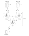
- FIG. 1 is a diagram for explaining and comparing V2X communication based on RAT before NR and V2X communication based on NR.
- V2X communication RAT prior to NR provides safety services based on V2X messages such as BSM (Basic Safety Message), CAM (Cooperative Awareness Message), and DENM (Decentralized Environmental Notification Message) This has been mainly discussed.
- the V2X message may include location information, dynamic information, attribute information, and the like.
- a UE may transmit a CAM of a periodic message type and/or a DENM of an event triggered message type to another UE.
- the CAM may include basic vehicle information such as vehicle dynamic state information such as direction and speed, vehicle static data such as dimensions, external lighting conditions, and route details.
- the terminal may broadcast CAM, and the latency of CAM may be less than 100 ms.
- a terminal may generate a DENM and transmit it to another terminal.
- all vehicles within the transmission range of the UE can receive CAM and/or DENM.
- DENM may have a higher priority than CAM.
- V2X scenarios may include vehicle platooning, advanced driving, extended sensors, remote driving, and the like.
- vehicles can dynamically form groups and move together. For example, to perform platoon operations based on vehicle platooning, vehicles belonging to the group may receive periodic data from the lead vehicle. For example, vehicles belonging to the group may shorten or widen the distance between vehicles using periodic data.
- vehicles can be semi-automated or fully automated.
- each vehicle may adjust trajectories or maneuvers based on data obtained from local sensors of proximate vehicles and/or proximate logical entities.
- each vehicle may mutually share driving intention with nearby vehicles.
- raw data or processed data obtained through local sensors, or live video data may be used for vehicles, logical entities, terminals of pedestrians, and / or may be interchanged between V2X application servers.
- a vehicle can recognize an environment that is more advanced than an environment that can be sensed using its own sensors.
- a remote driver or V2X application may operate or control the remote vehicle.
- a route can be predicted such as in public transportation
- cloud computing-based driving may be used to operate or control the remote vehicle.
- access to a cloud-based back-end service platform can be considered for remote driving.
- Embodiment (s) makes the contents related to path switching, switching failure, measurement report, etc. a technical task.
- One embodiment is a method of operating a sidelink remote UE in a wireless communication system, wherein the remote UE receives information related to measurement and reporting from a base station; the remote UE performing measurements on one or more candidate relay UEs; The remote UE performs a measurement report to the base station; and performing, by the remote UE, a PC5 connection establishment procedure with a target relay UE determined based on the measurement report, wherein the remote UE reports the connection establishment failure to the base station based on a connection failure related to the target relay UE.
- a remote UE in a wireless communication system, at least one processor; and at least one computer memory operably coupled to the at least one processor, wherein the computer memory stores instructions that, when executed, cause the at least one processor to perform operations, wherein the remote UE operates at a base station Receive information related to measurement and reporting from; the remote UE performing measurements on one or more candidate relay UEs; The remote UE performs a measurement report to the base station; and performing, by the remote UE, a PC5 connection establishment procedure with a target relay UE determined based on the measurement report, wherein the remote UE reports the connection establishment failure to the base station based on a connection failure related to the target relay UE. It is a remote UE that transmits a related cause value and maintains a connection with the base station.
- One embodiment is a processor for performing operations for a remote UE in a wireless communication system
- the operations may include: receiving, by the remote UE, information related to measurement and reporting from a base station; the remote UE performing measurements on one or more candidate relay UEs; The remote UE performs a measurement report to the base station; and performing, by the remote UE, a PC5 connection establishment procedure with a target relay UE determined based on the measurement report, wherein the remote UE reports the connection establishment failure to the base station based on a connection failure related to the target relay UE.
- a processor that transmits a related cause value and maintains a connection with the base station.
- the cause value may indicate failure to receive an RRC reconfiguration message from the base station.
- the RRC reconfiguration message may be related to Direct-to-indirect path switching to the target relay.
- the RRC reconfiguration message may include the ID of the target relay UE.
- the cause value may indicate PC5 connection establishment failure with the target relay UE.
- the measurement report may be Sidelink Discovery Reference Signals Received Power (SD-RSRP) related to the one or more candidate relays.
- SD-RSRP Sidelink Discovery Reference Signals Received Power
- the measurement report may be Sidelink Reference Signals Received Power (SL-RSRP) related to the one or more candidate relays.
- SL-RSRP Sidelink Reference Signals Received Power
- the measurement report may include an indicator indicating whether the measurement report is related to SD-RSRP or SL-RSRP.
- Different threshold values may be applied to the SD-RSRP and SL-RSRP used when determining the target relay UE.
- the one or more candidate relay UEs may be arranged in the order of highest RSRP signal strength.
- the measurement report may be sorted with priority given to candidate relay UEs in an RRC connected state.
- candidate relay UEs belonging to the same cell as the relay UE may be prioritized.
- direct-to-indirect path switching fails to establish an SL connection with a relay UE determined by the gNB
- the gNB is informed of this through the direct path, and the direct path is connected to the base station as it is to maintain service continuity.
- FIG. 1 is a diagram for explaining and comparing V2X communication based on RAT before NR and V2X communication based on NR.
- FIG 2 shows the structure of an LTE system according to an embodiment of the present disclosure.
- FIG 3 illustrates a radio protocol architecture for a user plane and a control plane, according to an embodiment of the present disclosure.
- FIG. 4 shows the structure of an NR system according to an embodiment of the present disclosure.
- 5 illustrates functional partitioning between NG-RAN and 5GC according to an embodiment of the present disclosure.
- FIG. 6 shows a structure of a radio frame of NR to which the embodiment(s) can be applied.
- FIG. 7 illustrates a slot structure of an NR frame according to an embodiment of the present disclosure.
- FIG. 8 illustrates a radio protocol architecture for SL communication according to an embodiment of the present disclosure.
- FIG 9 illustrates a radio protocol architecture for SL communication according to an embodiment of the present disclosure.
- FIG. 10 illustrates a procedure for a terminal to perform V2X or SL communication according to a transmission mode according to an embodiment of the present disclosure.
- 13 to 15 are diagrams for explaining the embodiment(s).
- 16 to 22 are views illustrating various devices to which the embodiment(s) may be applied.
- “/” and “,” should be interpreted as indicating “and/or”.
- “A/B” may mean “A and/or B”.
- “A, B” may mean “A and/or B”.
- “A/B/C” may mean “at least one of A, B and/or C”.
- “A, B, C” may mean “at least one of A, B and/or C”.
- “or” should be interpreted as indicating “and/or”.
- “A or B” can include “only A”, “only B”, and/or “both A and B”.
- “or” should be interpreted as indicating "in addition or alternatively.”
- CDMA code division multiple access
- FDMA frequency division multiple access
- TDMA time division multiple access
- OFDMA orthogonal frequency division multiple access
- SC-FDMA single carrier frequency division multiple access
- CDMA may be implemented with a radio technology such as universal terrestrial radio access (UTRA) or CDMA2000.
- TDMA may be implemented with a radio technology such as global system for mobile communications (GSM)/general packet radio service (GPRS)/enhanced data rates for GSM evolution (EDGE).
- GSM global system for mobile communications
- GPRS general packet radio service
- EDGE enhanced data rates for GSM evolution
- OFDMA may be implemented with a wireless technology such as institute of electrical and electronics engineers (IEEE) 802.11 (Wi-Fi), IEEE 802.16 (WiMAX), IEEE 802-20, evolved UTRA (E-UTRA), and the like.
- IEEE 802.16m is an evolution of IEEE 802.16e, and provides backward compatibility with a system based on IEEE 802.16e.
- UTRA is part of the universal mobile telecommunications system (UMTS).
- 3rd generation partnership project (3GPP) long term evolution (LTE) is a part of evolved UMTS (E-UMTS) that uses evolved-UMTS terrestrial radio access (E-UTRA), adopting OFDMA in downlink and SC in uplink -Adopt FDMA.
- LTE-A (advanced) is an evolution of 3GPP LTE.
- 5G NR a successor to LTE-A, is a new clean-slate mobile communication system with characteristics such as high performance, low latency, and high availability.
- 5G NR can utilize all available spectrum resources, including low-frequency bands below 1 GHz, medium-frequency bands between 1 GHz and 10 GHz, and high-frequency (millimeter wave) bands above 24 GHz.
- LTE-A or 5G NR is mainly described, but the technical idea according to an embodiment of the present disclosure is not limited thereto.
- E-UTRAN Evolved-UMTS Terrestrial Radio Access Network
- LTE Long Term Evolution
- the E-UTRAN includes a base station 20 providing a control plane and a user plane to a terminal 10.
- the terminal 10 may be fixed or mobile, and may be referred to by other terms such as a mobile station (MS), a user terminal (UT), a subscriber station (SS), a mobile terminal (MT), and a wireless device.
- the base station 20 refers to a fixed station that communicates with the terminal 10, and may be called other terms such as an evolved-NodeB (eNB), a base transceiver system (BTS), and an access point.
- eNB evolved-NodeB
- BTS base transceiver system
- Base stations 20 may be connected to each other through an X2 interface.
- the base station 20 is connected to an Evolved Packet Core (EPC) 30 through the S1 interface, and more specifically, to a Mobility Management Entity (MME) through the S1-MME and a Serving Gateway (S-GW) through the S1-U.
- EPC Evolved Packet Core
- MME Mobility Management Entity
- S-GW Serving Gateway
- the EPC 30 is composed of an MME, an S-GW, and a Packet Data Network-Gateway (P-GW).
- the MME has access information of the terminal or information about the capabilities of the terminal, and this information is mainly used for mobility management of the terminal.
- the S-GW is a gateway having E-UTRAN as an endpoint
- the P-GW is a gateway having PDN (Packet Date Network) as an endpoint.
- the layers of the Radio Interface Protocol between the terminal and the network are based on the lower 3 layers of the Open System Interconnection (OSI) standard model, which is widely known in communication systems, It can be divided into L2 (second layer) and L3 (third layer).
- OSI Open System Interconnection
- the physical layer belonging to the first layer provides an information transfer service using a physical channel
- the RRC (Radio Resource Control) layer located in the third layer provides radio resources between the terminal and the network. plays a role in controlling To this end, the RRC layer exchanges RRC messages between the terminal and the base station.
- 3(a) shows a radio protocol architecture for a user plane, according to an embodiment of the present disclosure.
- the user plane is a protocol stack for transmitting user data
- the control plane is a protocol stack for transmitting control signals.
- a physical layer provides an information transmission service to an upper layer using a physical channel.
- the physical layer is connected to a medium access control (MAC) layer, which is an upper layer, through a transport channel.
- MAC medium access control
- Data moves between the MAC layer and the physical layer through the transport channel. Transmission channels are classified according to how and with what characteristics data is transmitted through the air interface.
- the physical channel may be modulated using OFDM (Orthogonal Frequency Division Multiplexing) and utilizes time and frequency as radio resources.
- OFDM Orthogonal Frequency Division Multiplexing
- the MAC layer provides a service to a radio link control (RLC) layer, which is an upper layer, through a logical channel.
- RLC radio link control
- the MAC layer provides a mapping function from multiple logical channels to multiple transport channels.
- the MAC layer provides a logical channel multiplexing function by mapping a plurality of logical channels to a single transport channel.
- the MAC sublayer provides data transmission services on logical channels.
- the RLC layer performs concatenation, segmentation, and reassembly of RLC Serving Data Units (SDUs).
- SDUs RLC Serving Data Units
- the RLC layer has transparent mode (TM), unacknowledged mode (UM) and acknowledged mode , AM) provides three operation modes.
- AM RLC provides error correction through automatic repeat request (ARQ).
- the Radio Resource Control (RRC) layer is defined only in the control plane.
- the RRC layer is responsible for control of logical channels, transport channels, and physical channels in relation to configuration, re-configuration, and release of radio bearers.
- RB means a logical path provided by the first layer (physical layer or PHY layer) and the second layer (MAC layer, RLC layer, Packet Data Convergence Protocol (PDCP) layer) for data transfer between the UE and the network.
- MAC layer physical layer or PHY layer
- RLC layer Packet Data Convergence Protocol (PDCP) layer
- the functions of the PDCP layer in the user plane include delivery of user data, header compression and ciphering.
- the functions of the PDCP layer in the control plane include delivery of control plane data and encryption/integrity protection.
- Establishing an RB means a process of defining characteristics of a radio protocol layer and a channel and setting specific parameters and operation methods to provide a specific service.
- RBs can be further divided into two types: Signaling Radio Bearer (SRB) and Data Radio Bearer (DRB).
- SRB Signaling Radio Bearer
- DRB Data Radio Bearer
- the UE When an RRC connection is established between the RRC layer of the UE and the RRC layer of the E-UTRAN, the UE is in the RRC_CONNECTED state, otherwise it is in the RRC_IDLE state.
- the RRC_INACTIVE state is additionally defined, and the UE in the RRC_INACTIVE state can release the connection with the base station while maintaining the connection with the core network.
- a downlink transmission channel for transmitting data from a network to a terminal includes a broadcast channel (BCH) for transmitting system information and a downlink shared channel (SCH) for transmitting user traffic or control messages.
- Traffic or control messages of a downlink multicast or broadcast service may be transmitted through a downlink SCH or may be transmitted through a separate downlink multicast channel (MCH).
- an uplink transmission channel for transmitting data from a terminal to a network includes a random access channel (RACH) for transmitting an initial control message and an uplink shared channel (SCH) for transmitting user traffic or control messages.
- RACH random access channel
- Logical channels located above transport channels and mapped to transport channels include BCCH (Broadcast Control Channel), PCCH (Paging Control Channel), CCCH (Common Control Channel), MCCH (Multicast Control Channel), MTCH (Multicast Traffic Channel) Channel), etc.
- BCCH Broadcast Control Channel
- PCCH Paging Control Channel
- CCCH Common Control Channel
- MCCH Multicast Control Channel
- MTCH Multicast Traffic Channel
- a physical channel is composed of several OFDM symbols in the time domain and several sub-carriers in the frequency domain.
- One sub-frame is composed of a plurality of OFDM symbols in the time domain.
- a resource block is a resource allocation unit and is composed of a plurality of OFDM symbols and a plurality of sub-carriers.
- each subframe may use specific subcarriers of specific OFDM symbols (eg, a first OFDM symbol) of the corresponding subframe for a Physical Downlink Control Channel (PDCCH), that is, an L1/L2 control channel.
- PDCCH Physical Downlink Control Channel
- TTI Transmission Time Interval
- FIG. 4 shows the structure of an NR system according to an embodiment of the present disclosure.
- a Next Generation Radio Access Network may include a next generation-Node B (gNB) and/or an eNB that provides user plane and control plane protocol termination to a UE.
- gNB next generation-Node B
- eNB that provides user plane and control plane protocol termination to a UE.
- 4 illustrates a case including only gNB.
- gNB and eNB are connected to each other through an Xn interface.
- the gNB and the eNB are connected to a 5G Core Network (5GC) through an NG interface.
- 5GC 5G Core Network
- AMF access and mobility management function
- UPF user plane function
- 5 illustrates functional partitioning between NG-RAN and 5GC according to an embodiment of the present disclosure.
- the gNB provides inter-cell radio resource management (Inter Cell RRM), radio bearer management (RB control), connection mobility control, radio admission control, measurement setup and provision. (Measurement configuration & provision) and dynamic resource allocation.
- AMF may provide functions such as Non Access Stratum (NAS) security and idle state mobility processing.
- the UPF may provide functions such as mobility anchoring and PDU (Protocol Data Unit) processing.
- Session Management Function (SMF) may provide functions such as terminal IP (Internet Protocol) address allocation and PDU session control.
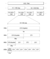
- FIG. 6 shows a structure of a radio frame of NR to which the present disclosure can be applied.
- radio frames can be used in uplink and downlink transmission in NR.
- a radio frame has a length of 10 ms and may be defined as two 5 ms half-frames (Half-Frame, HF).
- a half-frame may include five 1ms subframes (Subframes, SFs).
- a subframe may be divided into one or more slots, and the number of slots in a subframe may be determined according to a subcarrier spacing (SCS).
- SCS subcarrier spacing
- Each slot may include 12 or 14 OFDM(A) symbols according to a cyclic prefix (CP).
- CP cyclic prefix
- each slot may include 14 symbols.
- each slot may include 12 symbols.
- the symbol may include an OFDM symbol (or CP-OFDM symbol) and an SC-FDMA symbol (or DFT-s-OFDM symbol).
- Table 1 shows the number of symbols per slot according to the SCS setting ( ⁇ ) when a normal CP is used. ), the number of slots per frame ( ) and the number of slots per subframe ( ) exemplifies.
- Table 2 illustrates the number of symbols per slot, the number of slots per frame, and the number of slots per subframe according to the SCS when the extended CP is used.
- OFDM(A) numerology eg, SCS, CP length, etc.
- OFDM(A) numerology eg, SCS, CP length, etc.
- the (absolute time) interval of time resources e.g., subframes, slots, or TTIs
- TU Time Unit
- multiple numerologies or SCSs to support various 5G services can be supported. For example, when the SCS is 15 kHz, wide area in traditional cellular bands can be supported, and when the SCS is 30 kHz/60 kHz, dense-urban, lower latency latency and wider carrier bandwidth may be supported. When the SCS is 60 kHz or higher, a bandwidth greater than 24.25 GHz may be supported to overcome phase noise.
- An NR frequency band may be defined as two types of frequency ranges.
- the two types of frequency ranges may be FR1 and FR2.
- the number of frequency ranges may be changed, and for example, the two types of frequency ranges may be shown in Table 3 below.
- FR1 may mean "sub 6 GHz range”
- FR2 may mean “above 6 GHz range” and may be called millimeter wave (mmW).
- mmW millimeter wave
- FR1 may include a band of 410 MHz to 7125 MHz as shown in Table 4 below. That is, FR1 may include a frequency band of 6 GHz (or 5850, 5900, 5925 MHz, etc.) or higher. For example, a frequency band of 6 GHz (or 5850, 5900, 5925 MHz, etc.) or higher included in FR1 may include an unlicensed band. The unlicensed band may be used for various purposes, and may be used, for example, for vehicle communication (eg, autonomous driving).
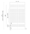
- FIG. 7 illustrates a slot structure of an NR frame according to an embodiment of the present disclosure.
- a slot includes a plurality of symbols in the time domain. For example, in the case of a normal CP, one slot includes 14 symbols, but in the case of an extended CP, one slot may include 12 symbols. Alternatively, in the case of a normal CP, one slot includes 7 symbols, but in the case of an extended CP, one slot may include 6 symbols.
- a carrier includes a plurality of subcarriers in the frequency domain.
- a resource block (RB) may be defined as a plurality of (eg, 12) consecutive subcarriers in the frequency domain.
- a bandwidth part (BWP) may be defined as a plurality of consecutive (P)RBs ((Physical) Resource Blocks) in the frequency domain, and may correspond to one numerology (eg, SCS, CP length, etc.) there is.
- a carrier may include up to N (eg, 5) BWPs. Data communication may be performed through an activated BWP.
- Each element may be referred to as a resource element (RE) in the resource grid, and one complex symbol may be mapped.
- RE resource element
- a radio interface between a terminal and a terminal or a radio interface between a terminal and a network may be composed of an L1 layer, an L2 layer, and an L3 layer.
- the L1 layer may mean a physical layer.
- the L2 layer may mean at least one of a MAC layer, an RLC layer, a PDCP layer, and an SDAP layer.
- the L3 layer may mean an RRC layer.
- V2X or SL (sidelink) communication will be described.
- FIG. 8 illustrates a radio protocol architecture for SL communication according to an embodiment of the present disclosure. Specifically, (a) of FIG. 8 shows a user plane protocol stack of LTE, and (b) of FIG. 8 shows a control plane protocol stack of LTE.
- FIG. 9 illustrates a radio protocol architecture for SL communication according to an embodiment of the present disclosure. Specifically, (a) of FIG. 9 shows a user plane protocol stack of NR, and (b) of FIG. 9 shows a control plane protocol stack of NR.
- FIG. 10 shows a synchronization source or synchronization reference of V2X according to an embodiment of the present disclosure.
- a terminal is synchronized directly to global navigation satellite systems (GNSS), or indirectly synchronized to GNSS through a terminal directly synchronized to GNSS (within network coverage or outside network coverage).
- GNSS global navigation satellite systems
- the UE can calculate the DFN and subframe number using Coordinated Universal Time (UTC) and (pre)set Direct Frame Number (DFN) offset.
- UTC Coordinated Universal Time
- DFN Direct Frame Number
- the terminal may be directly synchronized with the base station or synchronized with another terminal that is time/frequency synchronized with the base station.
- the base station may be an eNB or gNB.
- the terminal may receive synchronization information provided by a base station and be directly synchronized with the base station. After that, the terminal may provide synchronization information to other neighboring terminals.
- the base station timing is set as a synchronization criterion, the UE uses a cell associated with a corresponding frequency (when it is within cell coverage at the frequency), a primary cell, or a serving cell (when it is outside cell coverage at the frequency) for synchronization and downlink measurement. ) can be followed.
- a base station may provide synchronization settings for carriers used for V2X or SL communication.
- the terminal may follow the synchronization setting received from the base station. If the terminal did not detect any cell on the carrier used for the V2X or SL communication and did not receive synchronization settings from the serving cell, the terminal may follow the preset synchronization settings.
- the terminal may be synchronized with other terminals that do not directly or indirectly obtain synchronization information from the base station or GNSS.
- Synchronization source and preference may be set in advance for the terminal.
- the synchronization source and preference may be set through a control message provided by the base station.
- a SL sync source may be associated with a sync priority.
- a relationship between synchronization sources and synchronization priorities may be defined as shown in Table 14 or Table 15.
- Table 5 or Table 6 is only an example, and the relationship between synchronization sources and synchronization priorities may be defined in various forms.
- GNSS-based synchronization Base station-based synchronization (eNB/gNB-based synchronization) P0 GNSS base station P1 All terminals synchronized directly to GNSS All terminals synchronized directly to the base station P2 All terminals indirectly synchronized to GNSS All terminals indirectly synchronized to the base station P3 all other terminals GNSS P4 N/A All terminals synchronized directly to GNSS P5 N/A All terminals indirectly synchronized to GNSS P6 N/A all other terminals
- GNSS-based synchronization Base station-based synchronization (eNB/gNB-based synchronization) P0 GNSS base station P1 All terminals synchronized directly to GNSS All terminals synchronized directly to the base station P2 All terminals indirectly synchronized to GNSS All terminals indirectly synchronized to the base station P3 base station GNSS P4 All terminals synchronized directly to the base station All terminals synchronized directly to GNSS P5 All terminals indirectly synchronized to the base station All terminals indirectly synchronized to GNSS P6 Remaining terminal(s) with lower priority Remaining terminal(s) with lower priority
- a base station may include at least one of a gNB and an eNB.
- a UE may derive its transmission timing from an available synchronization criterion having the highest priority.
- SL synchronization signal Sidelink Synchronization Signal, SLSS
- SLSS Segment Synchronization Signal
- the SLSS is a SL-specific sequence and may include a Primary Sidelink Synchronization Signal (PSSS) and a Secondary Sidelink Synchronization Signal (SSSS).
- PSSS may be referred to as a sidelink primary synchronization signal (S-PSS)
- S-SSS sidelink secondary synchronization signal
- S-SSS sidelink secondary synchronization signal
- length-127 M-sequences can be used for S-PSS
- length-127 Gold-sequences can be used for S-SSS.
- the UE can detect an initial signal using S-PSS and acquire synchronization.
- the terminal may obtain detailed synchronization using S-PSS and S-SSS and detect a synchronization signal ID.
- PSBCH Physical Sidelink Broadcast Channel
- PSBCH Physical Sidelink Broadcast Channel
- the basic information includes information related to SLSS, duplex mode (DM), TDD UL/Time Division Duplex Uplink/Downlink (TDD UL/DL) configuration, resource pool related information, type of application related to SLSS, It may be a subframe offset, broadcast information, and the like.
- the payload size of PSBCH may be 56 bits including a 24-bit CRC.
- S-PSS, S-SSS, and PSBCH may be included in a block format (eg, SL SS (Synchronization Signal) / PSBCH block, hereinafter, S-SSB (Sidelink-Synchronization Signal Block)) supporting periodic transmission.
- the S-SSB may have the same numerology (ie, SCS and CP length) as a Physical Sidelink Control Channel (PSCCH)/Physical Sidelink Shared Channel (PSSCH) in a carrier, and the transmission bandwidth may be a (pre)set SL Sidelink BWP (Sidelink Channel). BWP).
- the bandwidth of the S-SSB may be 11 Resource Blocks (RBs).
- PSBCH may span 11 RBs.
- the frequency position of the S-SSB may be set (in advance). Therefore, the UE does not need to perform hypothesis detection in frequency to discover the S-SSB in the carrier.
- the transmitting terminal may transmit one or more S-SSBs to the receiving terminal within one S-SSB transmission period according to the SCS.
- the number of S-SSBs that the transmitting terminal transmits to the receiving terminal within one S-SSB transmission period may be pre-configured or configured for the transmitting terminal.
- the S-SSB transmission period may be 160 ms.
- an S-SSB transmission period of 160 ms may be supported.
- the transmitting terminal may transmit one or two S-SSBs to the receiving terminal within one S-SSB transmission period. For example, when the SCS is 30 kHz in FR1, the transmitting terminal may transmit one or two S-SSBs to the receiving terminal within one S-SSB transmission period. For example, when the SCS is 60 kHz in FR1, the transmitting terminal may transmit one, two or four S-SSBs to the receiving terminal within one S-SSB transmission period.
- the transmission mode may be referred to as a mode or a resource allocation mode.
- a transmission mode in LTE may be referred to as an LTE transmission mode
- a transmission mode in NR may be referred to as an NR resource allocation mode.
- (a) of FIG. 11 shows a terminal operation related to LTE transmission mode 1 or LTE transmission mode 3.
- (a) of FIG. 11 shows a terminal operation related to NR resource allocation mode 1.
- LTE transmission mode 1 may be applied to general SL communication
- LTE transmission mode 3 may be applied to V2X communication.
- (b) of FIG. 11 shows a terminal operation related to LTE transmission mode 2 or LTE transmission mode 4.
- (b) of FIG. 11 shows a terminal operation related to NR resource allocation mode 2.
- the base station may schedule SL resources to be used by the terminal for SL transmission.
- the base station may transmit information related to SL resources and/or information related to UL resources to the first terminal.
- the UL resource may include a PUCCH resource and/or a PUSCH resource.
- the UL resource may be a resource for reporting SL HARQ feedback to the base station.
- the first terminal may receive information related to dynamic grant (DG) resources and/or information related to configured grant (CG) resources from the base station.
- CG resources may include CG type 1 resources or CG type 2 resources.
- the DG resource may be a resource set/allocated by the base station to the first terminal through downlink control information (DCI).
- the CG resource may be a (periodic) resource configured/allocated by the base station to the first terminal through a DCI and/or RRC message.
- the base station may transmit an RRC message including information related to the CG resource to the first terminal.
- the base station may transmit an RRC message including information related to the CG resource to the first terminal, and the base station transmits a DCI related to activation or release of the CG resource. It can be transmitted to the first terminal.
- the first terminal may transmit a PSCCH (eg, Sidelink Control Information (SCI) or 1st-stage SCI) to the second terminal based on the resource scheduling.
- the first terminal may transmit a PSSCH (eg, 2nd-stage SCI, MAC PDU, data, etc.) related to the PSCCH to the second terminal.
- the first terminal may receive the PSFCH related to the PSCCH/PSSCH from the second terminal. For example, HARQ feedback information (eg, NACK information or ACK information) may be received from the second terminal through the PSFCH.
- the first terminal may transmit / report HARQ feedback information to the base station through PUCCH or PUSCH.
- the HARQ feedback information reported to the base station may be information that the first terminal generates based on the HARQ feedback information received from the second terminal.
- the HARQ feedback information reported to the base station may be information generated by the first terminal based on a rule set in advance.
- the DCI may be a DCI for SL scheduling.
- the format of the DCI may be DCI format 3_0 or DCI format 3_1. Table 7 shows an example of DCI for SL scheduling.
- the terminal can determine an SL transmission resource within an SL resource set by the base station / network or a preset SL resource there is.
- the set SL resource or the preset SL resource may be a resource pool.
- the terminal may autonomously select or schedule resources for SL transmission.
- the terminal may perform SL communication by selecting a resource by itself within a configured resource pool.
- the terminal may select a resource by itself within a selection window by performing a sensing and resource (re)selection procedure.
- the sensing may be performed in units of subchannels.
- the first terminal that has selected a resource within the resource pool by itself can transmit a PSCCH (eg, Sidelink Control Information (SCI) or 1st-stage SCI) to the second terminal using the resource.
- a PSCCH eg, Sidelink Control Information (SCI) or 1st-stage SCI
- the first terminal may transmit a PSSCH (eg, 2nd-stage SCI, MAC PDU, data, etc.) related to the PSCCH to the second terminal.
- the first terminal may receive the PSFCH related to the PSCCH/PSSCH from the second terminal.
- a first terminal may transmit SCI to a second terminal on a PSCCH.
- UE 1 may transmit two consecutive SCI (eg, 2-stage SCI) to UE 2 on PSCCH and/or PSSCH.
- UE 2 may decode two consecutive SCIs (eg, 2-stage SCI) in order to receive the PSSCH from UE 1.
- SCI transmitted on PSCCH may be referred to as a 1st SCI, 1st SCI, 1st-stage SCI or 1st-stage SCI format
- SCI transmitted on PSSCH is 2nd SCI, 2nd SCI, 2nd-stage SCI or It may be referred to as a 2nd-stage SCI format
- the 1st-stage SCI format may include SCI format 1-A
- the 2nd-stage SCI format may include SCI format 2-A and/or SCI format 2-B.
- Table 8 shows an example of the 1st-stage SCI format.
- Table 9 shows an example of a 2nd-stage SCI format.
- the first terminal may receive the PSFCH based on Table 10.
- UE 1 and UE 2 may determine PSFCH resources based on Table 10, and UE 2 may transmit HARQ feedback to UE 1 using the PSFCH resource.
- the first terminal may transmit SL HARQ feedback to the base station through PUCCH and/or PUSCH based on Table 11.
- Table 12 below is disclosure related to selection and reselection of sidelink relay UEs in 3GPP TS 36.331.
- the disclosure of Table 12 is used as a prior art of this disclosure, and for related necessary details, refer to 3GPP TS 36.331.
- connection management captured in a TR document (3GPP TR 38.836) related to Rel-17 NR SL and a procedure when path switching from direct to indirect.
- the remote UE needs to establish its own PDU session/DRB with the network before user plane data transmission.
- the remote UE In the PC5 unicast link setup procedure, the remote UE establishes L2 UE-to-Network relaying between the relay UEs before the remote UE establishes a Uu RRC connection with the network through the relay UE. It can be reused to establish a secure unicast link for
- the PC5 L2 configuration for transmission between the remote UE and the UE-to-Network Relay UE is defined in the standard. may be based on the configured RLC/MAC configuration. Establishment of Uu SRB1/SRB2 and DRB of the remote UE follows the legacy Uu configuration procedure for L2 UE-to-Network Relay.
- the higher-level connection establishment procedure shown in FIG. 12 is applied to the L2 UE-to-Network Relay.
- the Remote and Relay UE performs a discovery procedure and may establish a PC5-RRC connection in step S1201 based on the existing Rel-16 procedure.
- the remote UE may transmit a first RRC message (ie, RRCSetupRequest) for connection setup with the gNB through the Relay UE using the basic L2 configuration of PC5.
- the gNB responds to the remote UE with an RRCSetup message (S1203).
- RRCSetup The delivery of RRCSetup to the remote UE uses the default configuration of PC5. If the Relay UE is not started in RRC_CONNECTED, it must perform its own connection setup upon receipt of a message about PC5's default L2 configuration. Details for the relay UE to deliver the RRCSetupRequest / RRCSetup message to the remote UE in this step can be discussed in the WI step.
- step S1204 the gNB and the Relay UE perform a relay channel setup procedure through Uu.
- the Relay/Remote UE establishes an RLC channel for relaying SRB1 to the remote UE through PC5. This step prepares the relay channel for SRB1.
- step S1205 the remote UE SRB1 message (eg, RRCSetupComplete message) is transmitted to the gNB through the relay UE using the SRB1 relay channel through PC5. And the remote UE is RRC connected through Uu.
- RRCSetupComplete message eg, RRCSetupComplete message
- step S1206 the remote UE and the gNB configure security according to the legacy procedure, and the security message is delivered through the Relay UE.
- the gNB establishes an additional RLC channel between the gNB and the Relay UE for traffic relay.
- the Relay/Remote UE establishes an additional RLC channel between the Remote UE and the Relay UE for relaying traffic.
- the gNB transmits RRCReconfiguration to the remote UE through the relay UE to configure the relay SRB2/DRB.
- the remote UE transmits RRCReconfigurationComplete as a response to the gNB through the Relay UE.
- RRC reconfiguration and RRC disconnection procedures can reuse legacy RRC procedures with message content/configuration design left in the WI phase.
- RRC Connection Reestablishment and RRC Connection Resumption procedures can reuse the existing RRC procedures as a baseline by considering the connection establishment procedures of the L2 UE-to-Network Relay above to handle relay specific parts along with message content/configuration design. there is. Message content/composition may be defined later.
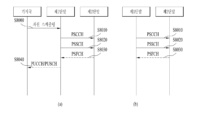
- FIG. 13 illustrates direct to indirect path conversion.
- the procedure of FIG. 13 may be used when a remote UE switches to an indirect relay UE for service continuity of L2 UE-to-Network Relay.
- the remote UE reports one or several candidate relay UEs.
- the remote UE may filter out appropriate relay UEs that meet higher layer criteria.
- the report may include the relay UE's ID and SL RSRP information, where PC5 measurement-related details may be determined later.
- step S1302 the gNB decides to switch to the target relay UE and the target (re)configuration is optionally transmitted to the relay UE.
- the RRC reconfiguration message for the remote UE may include the target relay UE's ID, target Uu, and PC5 configuration.
- step S1305 if the connection has not yet been established, the remote UE establishes a PC5 connection with the target relay UE.
- step S1306 the remote UE feeds back RRCReconfigurationComplete to the gNB via the target route using the target configuration provided in RRCReconfiguration.
- step S1307 the data path is switched.
- the remote may receive information related to measurement and reporting from the base station (S1401 in FIG. 14).
- the remote UE may perform measurements on one or more candidate relay UEs (S1402) and report a measurement to the base station (S1403). Thereafter, the remote UE may perform a PC5 connection establishment procedure with the target relay UE determined based on the measurement report (S1402).
- the remote UE may transmit a cause value related to the connection establishment failure to the base station and maintain the connection with the base station.
- the cause value may indicate failure to receive an RRC reconfiguration message from the base station.
- the RRC reconfiguration message may be related to Direct-to-indirect path switching to the target relay.
- the base station may determine path switching to the target relay UE and transmit an RRC reconfiguration message to the relay UE and the remote UE.
- the cause value may be for failure of the remote UE to receive an RRC reconfiguration message.
- the RRC reconfiguration message may include the ID of the target relay UE.
- the cause value may indicate PC5 connection establishment failure with the target relay UE.
- the remote UE may directly report the fail and cause value to the gNB.
- the base station receiving this may keep a direct link with the remote UE as described above.
- the base station may select a new relay UE based on information previously reported by the remote UE and notify the remote UE of the selected relay UE. If the remote UE previously reported only one candidate relay UE, the direct path may be kept.
- the remote UE may notify the gNB of the failure along with a cause value to the base station. Also, upon receiving the failure message from the remote UE, the gNB selects and informs a new relay UE among candidate relay UEs previously reported by the remote UE. If there is only one candidate relay UE reported previously, the current direct connection may be kept.
- the measurement report may be SD-RSRP (Sidelink Discovery Reference Signals Received Power) related to the one or more candidate relays.
- SD-RSRP Systemlink Discovery Reference Signals Received Power
- the RSRP value reported by the remote UE in the measurement configuration and reporting step may be the SD-RSRP value. This is because the remote UE has yet to establish an SL connection with the candidate relay UE. Even if the remote UE has an existing SL connection for the relay UE, reporting the SL-RSRP may not be meaningful. This is because the layer 2 SRC address used by the relay UE to establish a new connection will be different from the SRC address value used in the existing SL.
- the measurement report may be Sidelink Reference Signals Received Power (SL-RSRP).
- the measurement report may include an indicator indicating whether the measurement report is related to SD-RSRP or SL-RSRP. This is because when the gNB is configured to report RSRP, the remote UE selects and reports SL-RSRP or SD-RSRP based on UE implementation, but requires a flag indicating whether it is SL-RSRP or SD-RSRP.
- the RSRP value reported by the remote UE can select SD-RSRP or SL-RSRP based on only SD-RSRP (before connection is established yet) or UE implementation. In this case, an indication indicating whether SD-RSRP or SL-RSRP may be required.
- Different threshold values may be applied to the SD-RSRP and SL-RSRP used when determining the target relay UE. That is, when the SL-RSRP and SD-RSRP values are reported to the gNB together with the indication, the thresholds applied to the SL-RSRP and SD-RSRP may have different values.
- the gNB When the remote UE reports SL-RSRP or SD-RSRP to the gNB with an indication, the gNB must determine which relay UE is the appropriate UE by applying different threshold values for SD-RSRP and SL-RSRP. This is because SL-RSRP and SD-RSRP may differ in whether to apply power control due to path loss.
- SL-RSRP may not be available during indirect-to-direct path switching (eg, when the amount of data transmitted to SL is not sufficient for measurement).
- the remote UE/relay UE it is possible for the remote UE/relay UE to measure and report SD-RSRP instead of SL-RSRP (agreement).
- SD-RSRP instead of SL-RSRP (agreement).
- an indication may be required to distinguish the two with the same intention as the content of the invention described above.
- the one or more candidate relay UEs may be arranged in the order of highest RSRP signal strength.
- the number of candidate relay UEs that the remote UE can report may be limited.
- candidate relay UEs reported by the remote UE are listed up in the order of highest RSRP signal strength and reported to the gNB.
- a relay UE having a relatively poor RSRP signal strength may be omitted from the report.
- the measurement report may be sorted with priority given to candidate relay UEs in an RRC connected state. That is, candidate relay UEs reported by the remote UE may be listed up according to the RRC state.
- candidate relay UEs reported by the remote UE may be listed up according to the RRC state.
- the relay UE in the RRC CONNECTED state is listed up first, and according to the RRC INACTIVE and RRC IDLE states You can also set the link up order. This assumes that the RRC state in the discovery message includes a 2-bit (RRC CONNECTED/INACTIVE/IDLE) state. If the discovery message includes the RRC state of the candidate relay UE, latency can be reduced during path switch (HO) by listing up in the measurement report according to the RRC state.
- candidate relay UEs belonging to the same cell as the relay UE may be prioritized. That is, a method of listing up a relay UE in a camp on/connected state with the same cell ID as the highest priority may be used.
- relay UE IDs belonging to the same cell as the current serving cell of the remote UE are listed first, but the detailed order may be determined according to the RRC state. . That is, among candidate relay UEs belonging to the same cell as the remote UE, a relay UE in an RRC CONNECTED state may be listed up first, followed by an INACTIVE and IDLE list. After that, among relay UEs belonging to other cells, relay UEs in the RRC CONNECTED counterpart may be listed up, and may be listed in the order of INACTIVE and IDLE.
- candidate relay UEs reported by the remote UE may be listed up and reported in the order of signal strength of RSRP.
- the gNB may need an ID value to identify the relay UE.
- the relay UE is a CONNECTED UE
- the gNB can know who the candidate relay UE reported by the remote UE is.
- the gNB transmits the previously allocated temporal/local ID in the Discovery message, and the remote UE reports the ID of the candidate relay UE together with the corresponding temporal/local ID, this can be solved.
- the gNB cannot know who the actual relay UE is based only on the layer2 ID reported by the remote UE. Therefore, in direct-to-indirect path switching, if S1302 (RRC Reconfiguration and RRC Reconfiguration complete message of relay UE) exists before S1306 (RRCReconfigurationComplete message transmitted by remote UE), a method for identifying relay UE should be discussed. . In addition, specific discussion on the reason for performing S1303 ('RRC Reconfiguration and RRC Reconfiguration complete message' of relay UE) is required.
- the remote UE includes at least one processor; and at least one computer memory operably coupled to the at least one processor, wherein the computer memory stores instructions that, when executed, cause the at least one processor to perform operations, wherein the remote UE operates at a base station Receive information related to measurement and reporting from; the remote UE performing measurements on one or more candidate relay UEs; The remote UE performs a measurement report to the base station; and performing, by the remote UE, a PC5 connection establishment procedure with a target relay UE determined based on the measurement report, wherein the remote UE reports the connection establishment failure to the base station based on a connection failure related to the target relay UE.
- a related cause value may be transmitted and a connection with the base station may be maintained.
- the operations include: receiving, by the remote UE, information related to measurement and reporting from a base station; the remote UE performing measurements on one or more candidate relay UEs; The remote UE performs a measurement report to the base station; and performing, by the remote UE, a PC5 connection establishment procedure with a target relay UE determined based on the measurement report, wherein the remote UE reports the connection establishment failure to the base station based on a connection failure related to the target relay UE.
- a related cause value may be transmitted and a connection with the base station may be maintained.
- 15 is a diagram illustrating an indirect-to-direct path switching procedure.
- the RSRP value transmitted by the remote UE to the gNB may be an SL-RSRP value. Since the remote UE is in the CONNECTED state through the relay UE, transmitting the SL-RSRP rather than transmitting the SD-RSRP is a better value for the gNB to determine the SL situation. That is, the value reported by the remote UE during indirect-to-direct path switching operation is SL-RSRP.
- the relay UE does not know whether the remote UE has received RRC Reconfiguration related to HO. Therefore, the remote UE that has received the HO-related RRC Reconfiguration from the gNB must inform the relay UE of this. Alternatively, when the gNB transmits HO-related RRC Reconfiguration to the remote UE, it may inform the relay UE of this. This is to ensure that the relay UE no longer transmits DL data to the remote UE.
- the remote UE During indirect-to-direct path switching operation, if the remote UE receives an RRC Reconfiguration message related to HO, the remote UE must also know this. This is to suspend the data transmission of the relay UE.
- the method for the relay UE to know that the remote UE has received the HO-related RRC Reconfiguration message is (option 1) when the remote UE receives the HO-related RRC Reconfiguration message, it notifies the relay UE or (option 2) that the gNB receives the HO-related RRC Reconfiguration message.
- the RRC Reconfiguration message is transmitted to the remote UE, it is notified to the relay UE.
- the remote UE fails to transmit step 4 (RA to gNB) or S1505 (RRC Reconfiguration Complete message)
- the remote UE may maintain the current indirect link.
- the remote UE may transmit a resume message indicating that DL data may be transmitted again to the relay UE. That is, when the remote UE fails in HO, the remote UE transmits a resume message to the relay UE.
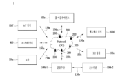
- FIG. 16 illustrates a communication system 1 applied to the present disclosure.
- a communication system 1 applied to the present disclosure includes a wireless device, a base station, and a network.
- the wireless device means a device that performs communication using a radio access technology (eg, 5G New RAT (NR), Long Term Evolution (LTE)), and may be referred to as a communication/wireless/5G device.
- wireless devices include robots 100a, vehicles 100b-1 and 100b-2, XR (eXtended Reality) devices 100c, hand-held devices 100d, and home appliances 100e. ), an Internet of Thing (IoT) device 100f, and an AI device/server 400.
- IoT Internet of Thing
- the vehicle may include a vehicle equipped with a wireless communication function, an autonomous vehicle, a vehicle capable of performing inter-vehicle communication, and the like.
- the vehicle may include an Unmanned Aerial Vehicle (UAV) (eg, a drone).
- UAV Unmanned Aerial Vehicle
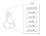
- XR devices include Augmented Reality (AR)/Virtual Reality (VR)/Mixed Reality (MR) devices, Head-Mounted Devices (HMDs), Head-Up Displays (HUDs) installed in vehicles, televisions, smartphones, It may be implemented in the form of a computer, wearable device, home appliance, digital signage, vehicle, robot, and the like.
- a portable device may include a smart phone, a smart pad, a wearable device (eg, a smart watch, a smart glass), a computer (eg, a laptop computer, etc.), and the like.
- Home appliances may include a TV, a refrigerator, a washing machine, and the like.
- IoT devices may include sensors, smart meters, and the like.
- a base station and a network may also be implemented as a wireless device, and a specific wireless device 200a may operate as a base station/network node to other wireless devices.
- the wireless devices 100a to 100f may be connected to the network 300 through the base station 200 .
- AI Artificial Intelligence
- the network 300 may be configured using a 3G network, a 4G (eg LTE) network, or a 5G (eg NR) network.
- the wireless devices 100a to 100f may communicate with each other through the base station 200/network 300, but may also communicate directly (eg, sidelink communication) without going through the base station/network.
- the vehicles 100b-1 and 100b-2 may perform direct communication (eg, vehicle to vehicle (V2V)/vehicle to everything (V2X) communication).
- IoT devices eg, sensors
- IoT devices may directly communicate with other IoT devices (eg, sensors) or other wireless devices 100a to 100f.
- Wireless communication/connection 150a, 150b, and 150c may be performed between the wireless devices 100a to 100f/base station 200 and the base station 200/base station 200.
- wireless communication/connection refers to various wireless connections such as uplink/downlink communication 150a, sidelink communication 150b (or D2D communication), and inter-base station communication 150c (e.g. relay, Integrated Access Backhaul (IAB)).
- IAB Integrated Access Backhaul
- Wireless communication/connection (150a, 150b, 150c) allows wireless devices and base stations/wireless devices, and base stations and base stations to transmit/receive radio signals to/from each other.
- the wireless communication/connection 150a, 150b, and 150c may transmit/receive signals through various physical channels.
- various signal processing processes eg, channel encoding/decoding, modulation/demodulation, resource mapping/demapping, etc.
- resource allocation processes etc.
- FIG 17 illustrates a wireless device applicable to the present disclosure.
- the first wireless device 100 and the second wireless device 200 may transmit and receive radio signals through various radio access technologies (eg, LTE, NR).
- ⁇ the first wireless device 100, the second wireless device 200 ⁇ is the ⁇ wireless device 100x, the base station 200 ⁇ of FIG. 16 and/or the ⁇ wireless device 100x, the wireless device 100x.
- ⁇ can correspond.
- the first wireless device 100 includes one or more processors 102 and one or more memories 104, and may additionally include one or more transceivers 106 and/or one or more antennas 108.
- the processor 102 controls the memory 104 and/or the transceiver 106 and may be configured to implement the descriptions, functions, procedures, suggestions, methods and/or flowcharts of operations disclosed herein.
- the processor 102 may process information in the memory 104 to generate first information/signal, and transmit a radio signal including the first information/signal through the transceiver 106.
- the processor 102 may receive a radio signal including the second information/signal through the transceiver 106, and then store information obtained from signal processing of the second information/signal in the memory 104.
- the memory 104 may be connected to the processor 102 and may store various information related to the operation of the processor 102 .
- memory 104 may perform some or all of the processes controlled by processor 102, or instructions for performing the descriptions, functions, procedures, suggestions, methods, and/or flowcharts of operations disclosed herein. It may store software codes including them.
- the processor 102 and memory 104 may be part of a communication modem/circuit/chip designed to implement a wireless communication technology (eg, LTE, NR).
- the transceiver 106 may be coupled to the processor 102 and may transmit and/or receive wireless signals via one or more antennas 108 .
- the transceiver 106 may include a transmitter and/or a receiver.
- the transceiver 106 may be used interchangeably with a radio frequency (RF) unit.
- a wireless device may mean a communication modem/circuit/chip.
- the second wireless device 200 includes one or more processors 202, one or more memories 204, and may further include one or more transceivers 206 and/or one or more antennas 208.
- Processor 202 controls memory 204 and/or transceiver 206 and may be configured to implement the descriptions, functions, procedures, suggestions, methods, and/or flowcharts of operations disclosed herein.
- the processor 202 may process information in the memory 204 to generate third information/signal, and transmit a radio signal including the third information/signal through the transceiver 206.
- the processor 202 may receive a radio signal including the fourth information/signal through the transceiver 206 and store information obtained from signal processing of the fourth information/signal in the memory 204 .
- the memory 204 may be connected to the processor 202 and may store various information related to the operation of the processor 202 .
- memory 204 may perform some or all of the processes controlled by processor 202, or instructions for performing the descriptions, functions, procedures, suggestions, methods, and/or flowcharts of operations disclosed herein. It may store software codes including them.
- the processor 202 and memory 204 may be part of a communication modem/circuit/chip designed to implement a wireless communication technology (eg, LTE, NR).
- the transceiver 206 may be coupled to the processor 202 and may transmit and/or receive wireless signals via one or more antennas 208 .
- the transceiver 206 may include a transmitter and/or a receiver.
- the transceiver 206 may be used interchangeably with an RF unit.
- a wireless device may mean a communication modem/circuit/chip.
- one or more protocol layers may be implemented by one or more processors 102, 202.
- one or more processors 102, 202 may implement one or more layers (eg, functional layers such as PHY, MAC, RLC, PDCP, RRC, SDAP).
- One or more processors 102, 202 may generate one or more Protocol Data Units (PDUs) and/or one or more Service Data Units (SDUs) in accordance with the descriptions, functions, procedures, proposals, methods and/or operational flow charts disclosed herein.
- PDUs Protocol Data Units
- SDUs Service Data Units
- processors 102, 202 may generate messages, control information, data or information according to the descriptions, functions, procedures, proposals, methods and/or operational flow diagrams disclosed herein.
- One or more processors 102, 202 generate PDUs, SDUs, messages, control information, data or signals (e.g., baseband signals) containing information according to the functions, procedures, proposals and/or methods disclosed herein , can be provided to one or more transceivers 106, 206.
- One or more processors 102, 202 may receive signals (eg, baseband signals) from one or more transceivers 106, 206, and descriptions, functions, procedures, proposals, methods, and/or flowcharts of operations disclosed herein PDUs, SDUs, messages, control information, data or information can be obtained according to these.
- signals eg, baseband signals
- One or more processors 102, 202 may be referred to as a controller, microcontroller, microprocessor or microcomputer.
- One or more processors 102, 202 may be implemented by hardware, firmware, software, or a combination thereof.
- ASICs Application Specific Integrated Circuits
- DSPs Digital Signal Processors
- DSPDs Digital Signal Processing Devices
- PLDs Programmable Logic Devices
- FPGAs Field Programmable Gate Arrays
- firmware or software may be implemented using firmware or software, and the firmware or software may be implemented to include modules, procedures, functions, and the like.
- Firmware or software configured to perform the descriptions, functions, procedures, suggestions, methods and/or operational flow diagrams disclosed herein may be included in one or more processors 102, 202 or stored in one or more memories 104, 204 and It can be driven by the above processors 102 and 202.
- the descriptions, functions, procedures, suggestions, methods and/or operational flow charts disclosed in this document may be implemented using firmware or software in the form of codes, instructions and/or sets of instructions.
- One or more memories 104, 204 may be coupled with one or more processors 102, 202 and may store various types of data, signals, messages, information, programs, codes, instructions and/or instructions.
- One or more memories 104, 204 may be comprised of ROM, RAM, EPROM, flash memory, hard drives, registers, cache memory, computer readable storage media, and/or combinations thereof.
- One or more memories 104, 204 may be located internally and/or external to one or more processors 102, 202. Additionally, one or more memories 104, 204 may be coupled to one or more processors 102, 202 through various technologies, such as wired or wireless connections.
- One or more transceivers 106, 206 may transmit user data, control information, radio signals/channels, etc., as referred to in the methods and/or operational flow charts herein, to one or more other devices.
- One or more transceivers 106, 206 may receive user data, control information, radio signals/channels, etc. referred to in descriptions, functions, procedures, proposals, methods and/or operational flow charts, etc. disclosed herein from one or more other devices. there is.
- one or more transceivers 106 and 206 may be connected to one or more processors 102 and 202 and transmit and receive wireless signals.
- one or more processors 102, 202 may control one or more transceivers 106, 206 to transmit user data, control information, or radio signals to one or more other devices. Additionally, one or more processors 102, 202 may control one or more transceivers 106, 206 to receive user data, control information, or radio signals from one or more other devices. In addition, one or more transceivers 106, 206 may be coupled with one or more antennas 108, 208, and one or more transceivers 106, 206 via one or more antennas 108, 208, as described herein, function. , procedures, proposals, methods and / or operation flowcharts, etc. can be set to transmit and receive user data, control information, radio signals / channels, etc.
- one or more antennas may be a plurality of physical antennas or a plurality of logical antennas (eg, antenna ports).
- One or more transceivers (106, 206) convert the received radio signals/channels from RF band signals in order to process the received user data, control information, radio signals/channels, etc. using one or more processors (102, 202). It can be converted into a baseband signal.
- One or more transceivers 106 and 206 may convert user data, control information, and radio signals/channels processed by one or more processors 102 and 202 from baseband signals to RF band signals.
- one or more of the transceivers 106, 206 may include (analog) oscillators and/or filters.
- Vehicles or autonomous vehicles may be implemented as mobile robots, vehicles, trains, manned/unmanned aerial vehicles (AVs), ships, and the like.
- AVs manned/unmanned aerial vehicles
- a vehicle or autonomous vehicle 100 includes an antenna unit 108, a communication unit 110, a control unit 120, a driving unit 140a, a power supply unit 140b, a sensor unit 140c, and an autonomous driving unit.
- a portion 140d may be included.
- the antenna unit 108 may be configured as part of the communication unit 110 .
- the communication unit 110 may transmit/receive signals (eg, data, control signals, etc.) with external devices such as other vehicles, base stations (e.g. base stations, roadside base stations, etc.), servers, and the like.
- the controller 120 may perform various operations by controlling elements of the vehicle or autonomous vehicle 100 .
- the controller 120 may include an Electronic Control Unit (ECU).
- the driving unit 140a may drive the vehicle or autonomous vehicle 100 on the ground.
- the driving unit 140a may include an engine, a motor, a power train, a wheel, a brake, a steering device, and the like.
- the power supply unit 140b supplies power to the vehicle or autonomous vehicle 100, and may include a wired/wireless charging circuit, a battery, and the like.
- the sensor unit 140c may obtain vehicle conditions, surrounding environment information, and user information.
- the sensor unit 140c includes an inertial measurement unit (IMU) sensor, a collision sensor, a wheel sensor, a speed sensor, an inclination sensor, a weight detection sensor, a heading sensor, a position module, and a vehicle forward.
- IMU inertial measurement unit
- /Can include a reverse sensor, battery sensor, fuel sensor, tire sensor, steering sensor, temperature sensor, humidity sensor, ultrasonic sensor, illuminance sensor, pedal position sensor, and the like.
- the autonomous driving unit 140d includes a technology for maintaining a driving lane, a technology for automatically adjusting speed such as adaptive cruise control, a technology for automatically driving along a predetermined route, and a technology for automatically setting a route when a destination is set and driving. technology can be implemented.
- the communication unit 110 may receive map data, traffic information data, and the like from an external server.
- the autonomous driving unit 140d may generate an autonomous driving route and a driving plan based on the acquired data.
- the controller 120 may control the driving unit 140a so that the vehicle or autonomous vehicle 100 moves along the autonomous driving path according to the driving plan (eg, speed/direction adjustment).
- the communicator 110 may non-/periodically obtain the latest traffic information data from an external server and obtain surrounding traffic information data from surrounding vehicles.
- the sensor unit 140c may acquire vehicle state and surrounding environment information.
- the autonomous driving unit 140d may update an autonomous driving route and a driving plan based on newly acquired data/information.
- the communication unit 110 may transmit information about a vehicle location, an autonomous driving route, a driving plan, and the like to an external server.
- the external server may predict traffic information data in advance using AI technology based on information collected from the vehicle or self-driving vehicles, and may provide the predicted traffic information data to the vehicle or self-driving vehicles.
- a vehicle may be implemented as a means of transportation, a train, an air vehicle, a ship, and the like.
- the vehicle 100 may include a communication unit 110, a control unit 120, a memory unit 130, an input/output unit 140a, and a position measurement unit 140b.
- the communication unit 110 may transmit/receive signals (eg, data, control signals, etc.) with other vehicles or external devices such as base stations.
- the controller 120 may perform various operations by controlling components of the vehicle 100 .
- the memory unit 130 may store data/parameters/programs/codes/commands supporting various functions of the vehicle 100 .
- the input/output unit 140a may output an AR/VR object based on information in the memory unit 130.
- the input/output unit 140a may include a HUD.
- the location measurement unit 140b may obtain location information of the vehicle 100 .
- the location information may include absolute location information of the vehicle 100, location information within a driving line, acceleration information, and location information with neighboring vehicles.
- the location measurement unit 140b may include GPS and various sensors.
- the communication unit 110 of the vehicle 100 may receive map information, traffic information, and the like from an external server and store them in the memory unit 130 .
- the location measurement unit 140b may acquire vehicle location information through GPS and various sensors and store it in the memory unit 130 .
- the controller 120 may generate a virtual object based on map information, traffic information, vehicle location information, etc., and the input/output unit 140a may display the created virtual object on a window in the vehicle (1410, 1420).
- the controller 120 may determine whether the vehicle 100 is normally operated within the driving line based on the vehicle location information. When the vehicle 100 abnormally deviate from the driving line, the controller 120 may display a warning on a window in the vehicle through the input/output unit 140a. In addition, the controller 120 may broadcast a warning message about driving abnormality to surrounding vehicles through the communication unit 110 .
- the controller 120 may transmit vehicle location information and information on driving/vehicle abnormalities to related agencies through the communication unit 110 .
- the XR device may be implemented as an HMD, a head-up display (HUD) provided in a vehicle, a television, a smartphone, a computer, a wearable device, a home appliance, a digital signage, a vehicle, a robot, and the like.
- HMD head-up display
- the XR device may be implemented as an HMD, a head-up display (HUD) provided in a vehicle, a television, a smartphone, a computer, a wearable device, a home appliance, a digital signage, a vehicle, a robot, and the like.
- HUD head-up display
- the XR device 100a may include a communication unit 110, a control unit 120, a memory unit 130, an input/output unit 140a, a sensor unit 140b, and a power supply unit 140c. .
- the communication unit 110 may transmit/receive signals (eg, media data, control signals, etc.) with external devices such as other wireless devices, portable devices, or media servers.
- Media data may include video, image, sound, and the like.
- the controller 120 may perform various operations by controlling components of the XR device 100a.
- the controller 120 may be configured to control and/or perform procedures such as video/image acquisition, (video/image) encoding, and metadata generation and processing.
- the memory unit 130 may store data/parameters/programs/codes/commands necessary for driving the XR device 100a/creating an XR object.
- the input/output unit 140a may obtain control information, data, etc. from the outside and output the created XR object.
- the input/output unit 140a may include a camera, a microphone, a user input unit, a display unit, a speaker, and/or a haptic module.
- the sensor unit 140b may obtain XR device status, surrounding environment information, user information, and the like.
- the sensor unit 140b may include a proximity sensor, an illuminance sensor, an acceleration sensor, a magnetic sensor, a gyro sensor, an inertial sensor, an RGB sensor, an IR sensor, a fingerprint recognition sensor, an ultrasonic sensor, an optical sensor, a microphone, and/or a radar. there is.
- the power supply unit 140c supplies power to the XR device 100a and may include a wired/wireless charging circuit, a battery, and the like.
- the memory unit 130 of the XR device 100a may include information (eg, data, etc.) necessary for generating an XR object (eg, AR/VR/MR object).
- the input/output unit 140a may obtain a command to operate the XR device 100a from a user, and the control unit 120 may drive the XR device 100a according to the user's driving command. For example, when a user tries to watch a movie, news, etc. through the XR device 100a, the control unit 120 transmits content request information to another device (eg, the mobile device 100b) or through the communication unit 130. can be sent to the media server.
- another device eg, the mobile device 100b
- the communication unit 130 can be sent to the media server.
- the communication unit 130 may download/stream content such as movies and news from another device (eg, the portable device 100b) or a media server to the memory unit 130 .
- the control unit 120 controls and/or performs procedures such as video/image acquisition, (video/image) encoding, metadata generation/processing, etc. for content, and acquisition through the input/output unit 140a/sensor unit 140b.
- An XR object may be created/output based on information about a surrounding space or a real object.
- the XR device 100a is wirelessly connected to the portable device 100b through the communication unit 110, and the operation of the XR device 100a may be controlled by the portable device 100b.
- the mobile device 100b may operate as a controller for the XR device 100a.
- the XR device 100a may acquire 3D location information of the portable device 100b and then generate and output an XR object corresponding to the portable device 100b.
- Robots may be classified into industrial, medical, household, military, and the like depending on the purpose or field of use.
- the robot 100 may include a communication unit 110, a control unit 120, a memory unit 130, an input/output unit 140a, a sensor unit 140b, and a driving unit 140c.
- the communication unit 110 may transmit/receive signals (eg, driving information, control signals, etc.) with external devices such as other wireless devices, other robots, or control servers.
- the controller 120 may perform various operations by controlling components of the robot 100 .
- the memory unit 130 may store data/parameters/programs/codes/commands supporting various functions of the robot 100.
- the input/output unit 140a may obtain information from the outside of the robot 100 and output the information to the outside of the robot 100 .
- the input/output unit 140a may include a camera, a microphone, a user input unit, a display unit, a speaker, and/or a haptic module.
- the sensor unit 140b may obtain internal information of the robot 100, surrounding environment information, user information, and the like.
- the sensor unit 140b may include a proximity sensor, an illuminance sensor, an acceleration sensor, a magnetic sensor, a gyro sensor, an inertial sensor, an IR sensor, a fingerprint recognition sensor, an ultrasonic sensor, an optical sensor, a microphone, a radar, and the like.
- the driving unit 140c may perform various physical operations such as moving a robot joint. In addition, the driving unit 140c may make the robot 100 drive on the ground or fly in the air.
- the driving unit 140c may include actuators, motors, wheels, brakes, propellers, and the like.
- AI devices include fixed or mobile devices such as TVs, projectors, smartphones, PCs, laptops, digital broadcasting terminals, tablet PCs, wearable devices, set-top boxes (STBs), radios, washing machines, refrigerators, digital signage, robots, and vehicles. It can be implemented with possible devices and the like.
- fixed or mobile devices such as TVs, projectors, smartphones, PCs, laptops, digital broadcasting terminals, tablet PCs, wearable devices, set-top boxes (STBs), radios, washing machines, refrigerators, digital signage, robots, and vehicles. It can be implemented with possible devices and the like.
- the AI device 100 includes a communication unit 110, a control unit 120, a memory unit 130, an input/output unit 140a/140b, a running processor unit 140c, and a sensor unit 140d.
- a communication unit 110 can include a Wi-Fi connection, a Wi-Fi connection, a Wi-Fi connection, a Wi-Fi connection, a Wi-Fi connection, a Wi-Fi connection, a Wi-Fi connection, a Wi-Fi connection, and a wireless connection, and a wireless connection, and a wireless connection, and a wireless connection, and a wireless connection, and a wireless connection, and a wireless connection, and a wireless connection, and a wireless connection, and a wireless connection, a Wi-Fi connection, a Wi-Fi connection, a Wi-Fi connection, a Wi-Fi connection, a Wi-Fi connection, a Wi-Fi connection, a Wi-Fi connection, a Wi-Fi connection, a Wi-Fi connection, a Wi-Fi connection, a Wi-Fi connection,
- the communication unit 110 transmits wired/wireless signals (eg, sensor information) with external devices such as other AI devices (eg, FIG. 16, 100x, 200, 400) or AI servers (eg, 400 in FIG. , user input, learning model, control signal, etc.) can be transmitted and received.
- external devices such as other AI devices (eg, FIG. 16, 100x, 200, 400) or AI servers (eg, 400 in FIG. , user input, learning model, control signal, etc.) can be transmitted and received.
- the communication unit 110 may transmit information in the memory unit 130 to an external device or transmit a signal received from the external device to the memory unit 130 .
- the controller 120 may determine at least one feasible operation of the AI device 100 based on information determined or generated using a data analysis algorithm or a machine learning algorithm. In addition, the controller 120 may perform the determined operation by controlling components of the AI device 100 . For example, the controller 120 may request, retrieve, receive, or utilize data from the learning processor unit 140c or the memory unit 130, and may perform a predicted operation among at least one feasible operation or an operation determined to be desirable. Components of the AI device 100 may be controlled to execute an operation. In addition, the control unit 120 collects history information including user feedback on the operation contents or operation of the AI device 100 and stores it in the memory unit 130 or the running processor unit 140c, or the AI server ( 16, 400) can be transmitted to an external device. The collected history information can be used to update the learning model.
- the memory unit 130 may store data supporting various functions of the AI device 100 .
- the memory unit 130 may store data obtained from the input unit 140a, data obtained from the communication unit 110, output data from the learning processor unit 140c, and data obtained from the sensing unit 140.
- the memory unit 130 may store control information and/or software codes necessary for operation/execution of the control unit 120 .
- the input unit 140a may obtain various types of data from the outside of the AI device 100.
- the input unit 140a may obtain learning data for model learning and input data to which the learning model is to be applied.
- the input unit 140a may include a camera, a microphone, and/or a user input unit.
- the output unit 140b may generate an output related to sight, hearing, or touch.
- the output unit 140b may include a display unit, a speaker, and/or a haptic module.
- the sensing unit 140 may obtain at least one of internal information of the AI device 100, surrounding environment information of the AI device 100, and user information by using various sensors.
- the sensing unit 140 may include a proximity sensor, an illuminance sensor, an acceleration sensor, a magnetic sensor, a gyro sensor, an inertial sensor, an RGB sensor, an IR sensor, a fingerprint recognition sensor, an ultrasonic sensor, an optical sensor, a microphone, and/or a radar. there is.
- the learning processor unit 140c may learn a model composed of an artificial neural network using learning data.
- the running processor unit 140c may perform AI processing together with the running processor unit of the AI server (400 in FIG. 16 ).
- the learning processor unit 140c may process information received from an external device through the communication unit 110 and/or information stored in the memory unit 130 .
- the output value of the learning processor unit 140c may be transmitted to an external device through the communication unit 110 and/or stored in the memory unit 130.
- Embodiments as described above can be applied to various mobile communication systems.
Abstract
An embodiment is a method for operating a sidelink remote UE in a wireless communication system, the method comprising the steps in which the remote UE: receives information related to measurement and reporting from a base station; performs a measurement on one or more candidate relay UEs; performs measurement reporting to the base station; and performs a PC5 connection establishment procedure with a target relay UE determined on the basis of the measurement reporting, wherein the remote UE transmits a cause value, related to failure to establish the connection, to the base station on the basis of a connection failure related to the target relay UE, and maintains a connection with the base station.
Description
이하의 설명은 무선 통신 시스템에 대한 것으로, 보다 상세하게는 사이드링크 릴레이에서 리모트 UE의 path switching 및 측정 보고에 관련된 방법 및 장치이다. The following description is for a wireless communication system, and more specifically, a method and apparatus related to path switching and measurement reporting of a remote UE in a sidelink relay.
무선 통신 시스템이 음성이나 데이터 등과 같은 다양한 종류의 통신 서비스를 제공하기 위해 광범위하게 전개되고 있다. 일반적으로 무선 통신 시스템은 가용한 시스템 자원(대역폭, 전송 파워 등)을 공유하여 다중 사용자와의 통신을 지원할 수 있는 다중 접속(multiple access) 시스템이다. 다중 접속 시스템의 예들로는 CDMA(code division multiple access) 시스템, FDMA(frequency division multiple access) 시스템, TDMA(time division multiple access) 시스템, OFDMA(orthogonal frequency division multiple access) 시스템, SC-FDMA(single carrier frequency division multiple access) 시스템, MC-FDMA(multi carrier frequency division multiple access) 시스템 등이 있다.A wireless communication system is widely deployed to provide various types of communication services such as voice and data. In general, a wireless communication system is a multiple access system capable of supporting communication with multiple users by sharing available system resources (bandwidth, transmission power, etc.). Examples of the multiple access system include a code division multiple access (CDMA) system, a frequency division multiple access (FDMA) system, a time division multiple access (TDMA) system, an orthogonal frequency division multiple access (OFDMA) system, and a single carrier frequency (SC-FDMA) system. There is a division multiple access (MC-FDMA) system and a multi carrier frequency division multiple access (MC-FDMA) system.
무선 통신 시스템에서는 LTE, LTE-A, WiFi 등의 다양한 RAT(Radio Access Technology)이 사용되고 있으며, 5G 도 여기에 포함된다. 5G의 세 가지 주요 요구 사항 영역은 (1) 개선된 모바일 광대역 (Enhanced Mobile Broadband, eMBB) 영역, (2) 다량의 머신 타입 통신 (massive Machine Type Communication, mMTC) 영역 및 (3) 초-신뢰 및 저 지연 통신 (Ultra-reliable and Low Latency Communications, URLLC) 영역을 포함한다. 일부 사용 예(Use Case)는 최적화를 위해 다수의 영역들이 요구될 수 있고, 다른 사용 예는 단지 하나의 핵심 성능 지표 (Key Performance Indicator, KPI)에만 포커싱될 수 있다. 5G는 이러한 다양한 사용 예들을 유연하고 신뢰할 수 있는 방법으로 지원하는 것이다. In wireless communication systems, various radio access technologies (RATs) such as LTE, LTE-A, and WiFi are used, including 5G. The three main requirement areas for 5G are (1) Enhanced Mobile Broadband (eMBB) area, (2) Massive Machine Type Communication (mMTC) area, and (3) Hyper-reliability and It includes the Ultra-reliable and Low Latency Communications (URLLC) area. Some use cases may require multiple areas for optimization, while other use cases may focus on just one key performance indicator (KPI). 5G supports these diverse use cases in a flexible and reliable way.
eMBB는 기본적인 모바일 인터넷 액세스를 훨씬 능가하게 하며, 풍부한 양방향 작업, 클라우드 또는 증강 현실에서 미디어 및 엔터테인먼트 애플리케이션을 커버한다. 데이터는 5G의 핵심 동력 중 하나이며, 5G 시대에서 처음으로 전용 음성 서비스를 볼 수 없을 수 있다. 5G에서, 음성은 단순히 통신 시스템에 의해 제공되는 데이터 연결을 사용하여 응용 프로그램으로서 처리될 것이 기대된다. 증가된 트래픽 양(volume)을 위한 주요 원인들은 콘텐츠 크기의 증가 및 높은 데이터 전송률을 요구하는 애플리케이션 수의 증가이다. 스트리밍 서비스 (오디오 및 비디오), 대화형 비디오 및 모바일 인터넷 연결은 더 많은 장치가 인터넷에 연결될수록 더 널리 사용될 것이다. 이러한 많은 응용 프로그램들은 사용자에게 실시간 정보 및 알림을 푸쉬하기 위해 항상 켜져 있는 연결성이 필요하다. 클라우드 스토리지 및 애플리케이션은 모바일 통신 플랫폼에서 급속히 증가하고 있으며, 이것은 업무 및 엔터테인먼트 모두에 적용될 수 있다. 그리고, 클라우드 스토리지는 상향링크 데이터 전송률의 성장을 견인하는 특별한 사용 예이다. 5G는 또한 클라우드의 원격 업무에도 사용되며, 촉각 인터페이스가 사용될 때 우수한 사용자 경험을 유지하도록 훨씬 더 낮은 단-대-단(end-to-end) 지연을 요구한다. 엔터테인먼트 예를 들어, 클라우드 게임 및 비디오 스트리밍은 모바일 광대역 능력에 대한 요구를 증가시키는 또 다른 핵심 요소이다. 엔터테인먼트는 기차, 차 및 비행기와 같은 높은 이동성 환경을 포함하는 어떤 곳에서든지 스마트폰 및 태블릿에서 필수적이다. 또 다른 사용 예는 엔터테인먼트를 위한 증강 현실 및 정보 검색이다. 여기서, 증강 현실은 매우 낮은 지연과 순간적인 데이터 양을 필요로 한다.eMBB goes far beyond basic mobile internet access, and covers rich interactive work, media and entertainment applications in the cloud or augmented reality. Data is one of the key drivers of 5G, and we may not see dedicated voice services for the first time in the 5G era. In 5G, voice is expected to be handled as an application simply using the data connection provided by the communication system. The main causes for the increased traffic volume are the increase in content size and the increase in the number of applications requiring high data rates. Streaming services (audio and video), interactive video and mobile internet connections will become more widely used as more devices connect to the internet. Many of these applications require always-on connectivity to push real-time information and notifications to users. Cloud storage and applications are rapidly growing in mobile communication platforms, which can be applied to both work and entertainment. And, cloud storage is a special use case that drives the growth of uplink data transmission rate. 5G is also used for remote work in the cloud, requiring much lower end-to-end latency to maintain a good user experience when tactile interfaces are used. Entertainment Cloud gaming and video streaming, for example, are another key factor driving the demand for mobile broadband capabilities. Entertainment is essential on smartphones and tablets anywhere including in highly mobile environments such as trains, cars and airplanes. Another use case is augmented reality for entertainment and information retrieval. Here, augmented reality requires very low latency and instantaneous amount of data.
또한, 가장 많이 예상되는 5G 사용 예 중 하나는 모든 분야에서 임베디드 센서를 원활하게 연결할 수 있는 기능 즉, mMTC에 관한 것이다. 2020년까지 잠재적인 IoT 장치들은 204 억 개에 이를 것으로 예측된다. 산업 IoT는 5G가 스마트 도시, 자산 추적(asset tracking), 스마트 유틸리티, 농업 및 보안 인프라를 가능하게 하는 주요 역할을 수행하는 영역 중 하나이다.In addition, one of the most expected 5G use cases is the ability to seamlessly connect embedded sensors in all fields, i.e. mMTC. By 2020, potential IoT devices are predicted to reach 20.4 billion. Industrial IoT is one area where 5G is playing a key role enabling smart cities, asset tracking, smart utilities, agriculture and security infrastructure.
URLLC는 주요 인프라의 원격 제어 및 자체-구동 차량(self-driving vehicle)과 같은 초 신뢰 / 이용 가능한 지연이 적은 링크를 통해 산업을 변화시킬 새로운 서비스를 포함한다. 신뢰성과 지연의 수준은 스마트 그리드 제어, 산업 자동화, 로봇 공학, 드론 제어 및 조정에 필수적이다.URLLC includes new services that will change the industry through ultra-reliable/available low-latency links such as remote control of critical infrastructure and self-driving vehicles. This level of reliability and latency is essential for smart grid control, industrial automation, robotics, and drone control and coordination.
다음으로, 다수의 사용 예들에 대해 보다 구체적으로 살펴본다.Next, a number of use cases will be looked at in more detail.
5G는 초당 수백 메가 비트에서 초당 기가 비트로 평가되는 스트림을 제공하는 수단으로 FTTH (fiber-to-the-home) 및 케이블 기반 광대역 (또는 DOCSIS)을 보완할 수 있다. 이러한 빠른 속도는 가상 현실과 증강 현실뿐 아니라 4K 이상(6K, 8K 및 그 이상)의 해상도로 TV를 전달하는데 요구된다. VR(Virtual Reality) 및 AR(Augmented Reality) 애플리케이션들은 거의 몰입형(immersive) 스포츠 경기를 포함한다. 특정 응용 프로그램은 특별한 네트워크 설정이 요구될 수 있다. 예를 들어, VR 게임의 경우, 게임 회사들이 지연을 최소화하기 위해 코어 서버를 네트워크 오퍼레이터의 에지 네트워크 서버와 통합해야 할 수 있다.5G can complement fiber-to-the-home (FTTH) and cable-based broadband (or DOCSIS) as a means of delivering streams rated at hundreds of megabits per second to gigabits per second. These high speeds are required to deliver TV with resolutions above 4K (6K, 8K and beyond) as well as virtual and augmented reality. Virtual Reality (VR) and Augmented Reality (AR) applications include mostly immersive sports competitions. Certain applications may require special network settings. For example, in the case of VR games, game companies may need to integrate their core servers with the network operator's edge network servers to minimize latency.
자동차(Automotive)는 차량에 대한 이동 통신을 위한 많은 사용 예들과 함께 5G에 있어 중요한 새로운 동력이 될 것으로 예상된다. 예를 들어, 승객을 위한 엔터테인먼트는 동시의 높은 용량과 높은 이동성 모바일 광대역을 요구한다. 그 이유는 미래의 사용자는 그들의 위치 및 속도와 관계 없이 고품질의 연결을 계속해서 기대하기 때문이다. 자동차 분야의 다른 활용 예는 증강 현실 대시보드이다. 이는 운전자가 앞면 창을 통해 보고 있는 것 위에 어둠 속에서 물체를 식별하고, 물체의 거리와 움직임에 대해 운전자에게 말해주는 정보를 겹쳐서 디스플레이 한다. 미래에, 무선 모듈은 차량들 간의 통신, 차량과 지원하는 인프라구조 사이에서 정보 교환 및 자동차와 다른 연결된 디바이스들(예를 들어, 보행자에 의해 수반되는 디바이스들) 사이에서 정보 교환을 가능하게 한다. 안전 시스템은 운전자가 보다 안전한 운전을 할 수 있도록 행동의 대체 코스들을 안내하여 사고의 위험을 낮출 수 있게 한다. 다음 단계는 원격 조종되거나 자체 운전 차량(self-driven vehicle)이 될 것이다. 이는 서로 다른 자체 운전 차량들 사이 및 자동차와 인프라 사이에서 매우 신뢰성이 있고, 매우 빠른 통신을 요구한다. 미래에, 자체 운전 차량이 모든 운전 활동을 수행하고, 운전자는 차량 자체가 식별할 수 없는 교통 이상에만 집중하도록 할 것이다. 자체 운전 차량의 기술적 요구 사항은 트래픽 안전을 사람이 달성할 수 없을 정도의 수준까지 증가하도록 초 저 지연과 초고속 신뢰성을 요구한다.Automotive is expected to be an important new driver for 5G, with many use cases for mobile communications on vehicles. For example, entertainment for passengers requires simultaneous high-capacity and high-mobility mobile broadband. The reason is that future users will continue to expect high-quality connections regardless of their location and speed. Another use case in the automotive sector is augmented reality dashboards. It identifies objects in the dark over what the driver sees through the front window, and overlays information that tells the driver about the object's distance and movement. In the future, wireless modules will enable communication between vehicles, exchange of information between vehicles and supporting infrastructure, and exchange of information between vehicles and other connected devices (eg devices carried by pedestrians). A safety system can help reduce the risk of an accident by guiding the driver through alternate courses of action to make driving safer. The next step will be remotely controlled or self-driven vehicles. This requires very reliable and very fast communication between different self-driving vehicles and between the vehicle and the infrastructure. In the future, self-driving vehicles will perform all driving activities, leaving drivers to focus only on traffic anomalies that the vehicle itself cannot identify. The technical requirements of self-driving vehicles require ultra-low latency and ultra-high reliability to increase traffic safety to levels that are unattainable by humans.
스마트 사회(smart society)로서 언급되는 스마트 도시와 스마트 홈은 고밀도 무선 센서 네트워크로 임베디드될 것이다. 지능형 센서의 분산 네트워크는 도시 또는 집의 비용 및 에너지-효율적인 유지에 대한 조건을 식별할 것이다. 유사한 설정이 각 가정을 위해 수행될 수 있다. 온도 센서, 창 및 난방 컨트롤러, 도난 경보기 및 가전 제품들은 모두 무선으로 연결된다. 이러한 센서들 중 많은 것들이 전형적으로 낮은 데이터 전송 속도, 저전력 및 저비용이다. 하지만, 예를 들어, 실시간 HD 비디오는 감시를 위해 특정 타입의 장치에서 요구될 수 있다.Smart cities and smart homes, referred to as smart society, will be embedded with high-density wireless sensor networks. A distributed network of intelligent sensors will identify conditions for cost and energy-efficient maintenance of a city or home. A similar setup can be done for each household. Temperature sensors, window and heating controllers, burglar alarms and appliances are all connected wirelessly. Many of these sensors are typically low data rates, low power and low cost. However, real-time HD video, for example, may be required in certain types of devices for surveillance.
열 또는 가스를 포함한 에너지의 소비 및 분배는 고도로 분산화되고 있어, 분산 센서 네트워크의 자동화된 제어가 요구된다. 스마트 그리드는 정보를 수집하고 이에 따라 행동하도록 디지털 정보 및 통신 기술을 사용하여 이런 센서들을 상호 연결한다. 이 정보는 공급 업체와 소비자의 행동을 포함할 수 있으므로, 스마트 그리드가 효율성, 신뢰성, 경제성, 생산의 지속 가능성 및 자동화된 방식으로 전기와 같은 연료들의 분배를 개선하도록 할 수 있다. 스마트 그리드는 지연이 적은 다른 센서 네트워크로 볼 수도 있다.The consumption and distribution of energy, including heat or gas, is highly decentralized, requiring automated control of distributed sensor networks. A smart grid interconnects these sensors using digital information and communication technologies to gather information and act on it. This information can include supplier and consumer behavior, allowing the smart grid to improve efficiency, reliability, affordability, sustainability of production and distribution of fuels such as electricity in an automated manner. The smart grid can also be viewed as another low-latency sensor network.
건강 부문은 이동 통신의 혜택을 누릴 수 있는 많은 응용 프로그램을 보유하고 있다. 통신 시스템은 멀리 떨어진 곳에서 임상 진료를 제공하는 원격 진료를 지원할 수 있다. 이는 거리에 대한 장벽을 줄이는데 도움을 주고, 거리가 먼 농촌에서 지속적으로 이용하지 못하는 의료 서비스들로의 접근을 개선시킬 수 있다. 이는 또한 중요한 진료 및 응급 상황에서 생명을 구하기 위해 사용된다. 이동 통신 기반의 무선 센서 네트워크는 심박수 및 혈압과 같은 파라미터들에 대한 원격 모니터링 및 센서들을 제공할 수 있다.The health sector has many applications that can benefit from mobile communications. The communication system may support telemedicine, which provides clinical care at a remote location. This can help reduce barriers to distance and improve access to health services that are not consistently available in remote rural areas. It is also used to save lives in critical care and emergencies. A mobile communication based wireless sensor network can provide remote monitoring and sensors for parameters such as heart rate and blood pressure.
무선 및 모바일 통신은 산업 응용 분야에서 점차 중요해지고 있다. 배선은 설치 및 유지 비용이 높다. 따라서, 케이블을 재구성할 수 있는 무선 링크들로의 교체 가능성은 많은 산업 분야에서 매력적인 기회이다. 그러나, 이를 달성하는 것은 무선 연결이 케이블과 비슷한 지연, 신뢰성 및 용량으로 동작하는 것과, 그 관리가 단순화될 것이 요구된다. 낮은 지연과 매우 낮은 오류 확률은 5G로 연결될 필요가 있는 새로운 요구 사항이다.Wireless and mobile communications are becoming increasingly important in industrial applications. Wiring is expensive to install and maintain. Thus, the possibility of replacing cables with reconfigurable wireless links is an attractive opportunity in many industries. However, achieving this requires that wireless connections operate with cable-like latency, reliability and capacity, and that their management be simplified. Low latency and very low error probability are the new requirements that need to be connected with 5G.
물류(logistics) 및 화물 추적(freight tracking)은 위치 기반 정보 시스템을 사용하여 어디에서든지 인벤토리(inventory) 및 패키지의 추적을 가능하게 하는 이동 통신에 대한 중요한 사용 예이다. 물류 및 화물 추적의 사용 예는 전형적으로 낮은 데이터 속도를 요구하지만 넓은 범위와 신뢰성 있는 위치 정보가 필요하다.Logistics and freight tracking are important use cases for mobile communications that use location-based information systems to enable tracking of inventory and packages from anywhere. Logistics and freight tracking use cases typically require low data rates, but wide range and reliable location information.
무선 통신 시스템은 가용한 시스템 자원(예를 들어, 대역폭, 전송 전력 등)을 공유하여 다중 사용자와의 통신을 지원하는 다중 접속(multiple access) 시스템이다. 다중 접속 시스템의 예로는 CDMA(code division multiple access) 시스템, FDMA(frequency division multiple access) 시스템, TDMA(time division multiple access) 시스템, OFDMA(orthogonal frequency division multiple access) 시스템, SC-FDMA(single carrier frequency division multiple access) 시스템, MC-FDMA(multi carrier frequency division multiple access) 시스템 등이 있다.A wireless communication system is a multiple access system that supports communication with multiple users by sharing available system resources (eg, bandwidth, transmission power, etc.). Examples of multiple access systems include a code division multiple access (CDMA) system, a frequency division multiple access (FDMA) system, a time division multiple access (TDMA) system, an orthogonal frequency division multiple access (OFDMA) system, and a single carrier frequency (SC-FDMA) system. There is a division multiple access (MC-FDMA) system and a multi carrier frequency division multiple access (MC-FDMA) system.
사이드링크(sidelink, SL)란 단말(User Equipment, UE)들 간에 직접적인 링크를 설정하여, 기지국(Base Station, BS)을 거치지 않고, 단말 간에 음성 또는 데이터 등을 직접 주고 받는 통신 방식을 말한다. SL는 급속도로 증가하는 데이터 트래픽에 따른 기지국의 부담을 해결할 수 있는 하나의 방안으로서 고려되고 있다.Sidelink (SL) refers to a communication method in which a direct link is established between user equipments (UEs) and voice or data is directly exchanged between the terminals without going through a base station (BS). The SL is being considered as a method for solving the burden of the base station due to rapidly increasing data traffic.
V2X(vehicle-to-everything)는 유/무선 통신을 통해 다른 차량, 보행자, 인프라가 구축된 사물 등과 정보를 교환하는 통신 기술을 의미한다. V2X는 V2V(vehicle-to-vehicle), V2I(vehicle-to-infrastructure), V2N(vehicle-to- network) 및 V2P(vehicle-to-pedestrian)와 같은 4 가지 유형으로 구분될 수 있다. V2X 통신은 PC5 인터페이스 및/또는 Uu 인터페이스를 통해 제공될 수 있다.V2X (vehicle-to-everything) refers to a communication technology that exchanges information with other vehicles, pedestrians, infrastructure-built objects, etc. through wired/wireless communication. V2X can be divided into four types: V2V (vehicle-to-vehicle), V2I (vehicle-to-infrastructure), V2N (vehicle-to-network), and V2P (vehicle-to-pedestrian). V2X communication may be provided through a PC5 interface and/or a Uu interface.
한편, 더욱 많은 통신 기기들이 더욱 큰 통신 용량을 요구하게 됨에 따라, 기존의 무선 액세스 기술(Radio Access Technology, RAT)에 비해 향상된 모바일 광대역 (mobile broadband) 통신에 대한 필요성이 대두되고 있다. 이에 따라, 신뢰도(reliability) 및 지연(latency)에 민감한 서비스 또는 단말을 고려한 통신 시스템이 논의되고 있는데, 개선된 이동 광대역 통신, 매시브 MTC(Machine Type Communication), URLLC(Ultra-Reliable and Low Latency Communication) 등을 고려한 차세대 무선 접속 기술을 새로운 RAT(new radio access technology) 또는 NR(new radio)이라 칭할 수 있다. NR에서도 V2X(vehicle-to-everything) 통신이 지원될 수 있다.Meanwhile, as more and more communication devices require greater communication capacity, a need for improved mobile broadband communication compared to conventional radio access technology (RAT) has emerged. Accordingly, communication systems considering reliability and latency-sensitive services or terminals are being discussed, such as improved mobile broadband communication, massive MTC (Machine Type Communication), and URLLC (Ultra-Reliable and Low Latency Communication). The next-generation radio access technology taking into account the above may be referred to as new radio access technology (RAT) or new radio (NR). Even in NR, vehicle-to-everything (V2X) communication may be supported.
도 1은 NR 이전의 RAT에 기반한 V2X 통신과 NR에 기반한 V2X 통신을 비교하여 설명하기 위한 도면이다.1 is a diagram for explaining and comparing V2X communication based on RAT before NR and V2X communication based on NR.
V2X 통신과 관련하여, NR 이전의 RAT에서는 BSM(Basic Safety Message), CAM(Cooperative Awareness Message), DENM(Decentralized Environmental Notification Message)과 같은 V2X 메시지를 기반으로, 안전 서비스(safety service)를 제공하는 방안이 주로 논의되었다. V2X 메시지는, 위치 정보, 동적 정보, 속성 정보 등을 포함할 수 있다. 예를 들어, 단말은 주기적인 메시지(periodic message) 타입의 CAM, 및/또는 이벤트 트리거 메시지(event triggered message) 타입의 DENM을 다른 단말에게 전송할 수 있다.Regarding V2X communication, RAT prior to NR provides safety services based on V2X messages such as BSM (Basic Safety Message), CAM (Cooperative Awareness Message), and DENM (Decentralized Environmental Notification Message) This has been mainly discussed. The V2X message may include location information, dynamic information, attribute information, and the like. For example, a UE may transmit a CAM of a periodic message type and/or a DENM of an event triggered message type to another UE.
예를 들어, CAM은 방향 및 속도와 같은 차량의 동적 상태 정보, 치수와 같은 차량 정적 데이터, 외부 조명 상태, 경로 내역 등 기본 차량 정보를 포함할 수 있다. 예를 들어, 단말은 CAM을 방송할 수 있으며, CAM의 지연(latency)은 100ms보다 작을 수 있다. 예를 들어, 차량의 고장, 사고 등의 돌발적인 상황이 발행하는 경우, 단말은 DENM을 생성하여 다른 단말에게 전송할 수 있다. 예를 들어, 단말의 전송 범위 내에 있는 모든 차량은 CAM 및/또는 DENM을 수신할 수 있다. 이 경우, DENM은 CAM 보다 높은 우선 순위를 가질 수 있다.For example, the CAM may include basic vehicle information such as vehicle dynamic state information such as direction and speed, vehicle static data such as dimensions, external lighting conditions, and route details. For example, the terminal may broadcast CAM, and the latency of CAM may be less than 100 ms. For example, when an unexpected situation such as a vehicle breakdown or an accident occurs, a terminal may generate a DENM and transmit it to another terminal. For example, all vehicles within the transmission range of the UE can receive CAM and/or DENM. In this case, DENM may have a higher priority than CAM.
이후, V2X 통신과 관련하여, 다양한 V2X 시나리오들이 NR에서 제시되고 있다. 예를 들어, 다양한 V2X 시나리오들은, 차량 플래투닝(vehicle platooning), 향상된 드라이빙(advanced driving), 확장된 센서들(extended sensors), 리모트 드라이빙(remote driving) 등을 포함할 수 있다. Since then, in relation to V2X communication, various V2X scenarios have been proposed in NR. For example, various V2X scenarios may include vehicle platooning, advanced driving, extended sensors, remote driving, and the like.
예를 들어, 차량 플래투닝을 기반으로, 차량들은 동적으로 그룹을 형성하여 함께 이동할 수 있다. 예를 들어, 차량 플래투닝에 기반한 플라툰 동작들(platoon operations)을 수행하기 위해, 상기 그룹에 속하는 차량들은 선두 차량으로부터 주기적인 데이터를 수신할 수 있다. 예를 들어, 상기 그룹에 속하는 차량들은 주기적인 데이터를 이용하여, 차량들 사이의 간격을 줄이거나 넓힐 수 있다. For example, based on vehicle platooning, vehicles can dynamically form groups and move together. For example, to perform platoon operations based on vehicle platooning, vehicles belonging to the group may receive periodic data from the lead vehicle. For example, vehicles belonging to the group may shorten or widen the distance between vehicles using periodic data.
예를 들어, 향상된 드라이빙을 기반으로, 차량은 반자동화 또는 완전 자동화될 수 있다. 예를 들어, 각 차량은 근접 차량 및/또는 근접 로지컬 엔티티(logical entity)의 로컬 센서(local sensor)에서 획득된 데이터를 기반으로, 궤도(trajectories) 또는 기동(maneuvers)을 조정할 수 있다. 또한, 예를 들어, 각 차량은 근접한 차량들과 드라이빙 인텐션(driving intention)을 상호 공유할 수 있다. For example, based on enhanced driving, vehicles can be semi-automated or fully automated. For example, each vehicle may adjust trajectories or maneuvers based on data obtained from local sensors of proximate vehicles and/or proximate logical entities. Also, for example, each vehicle may mutually share driving intention with nearby vehicles.
예를 들어, 확장 센서들을 기반으로, 로컬 센서들을 통해 획득된 로 데이터(raw data) 또는 처리된 데이터(processed data), 또는 라이브 비디오 데이터(live video data)는 차량, 로지컬 엔티티, 보행자들의 단말 및/또는 V2X 응용 서버 간에 상호 교환될 수 있다. 따라서, 예를 들어, 차량은 자체 센서를 이용하여 감지할 수 있는 환경 보다 향상된 환경을 인식할 수 있다. For example, based on extended sensors, raw data or processed data obtained through local sensors, or live video data may be used for vehicles, logical entities, terminals of pedestrians, and / or may be interchanged between V2X application servers. Thus, for example, a vehicle can recognize an environment that is more advanced than an environment that can be sensed using its own sensors.
예를 들어, 리모트 드라이빙을 기반으로, 운전을 하지 못하는 사람 또는 위험한 환경에 위치한 리모트 차량을 위해, 리모트 드라이버 또는 V2X 애플리케이션은 상기 리모트 차량을 동작 또는 제어할 수 있다. 예를 들어, 대중 교통과 같이 경로를 예측할 수 있는 경우, 클라우드 컴퓨팅 기반의 드라이빙이 상기 리모트 차량의 동작 또는 제어에 이용될 수 있다. 또한, 예를 들어, 클라우드 기반의 백엔드 서비스 플랫폼(cloud-based back-end service platform)에 대한 액세스가 리모트 드라이빙을 위해 고려될 수 있다.For example, based on remote driving, for a person who cannot drive or a remote vehicle located in a dangerous environment, a remote driver or V2X application may operate or control the remote vehicle. For example, when a route can be predicted, such as in public transportation, cloud computing-based driving may be used to operate or control the remote vehicle. Also, for example, access to a cloud-based back-end service platform can be considered for remote driving.
한편, 차량 플래투닝, 향상된 드라이빙, 확장된 센서들, 리모트 드라이빙 등 다양한 V2X 시나리오들에 대한 서비스 요구사항(service requirements)들을 구체화하는 방안이 NR에 기반한 V2X 통신에서 논의되고 있다.On the other hand, ways to specify service requirements for various V2X scenarios such as vehicle platooning, enhanced driving, extended sensors, and remote driving are being discussed in NR-based V2X communication.
실시예(들)은 path switching 및 전환 실패, 측정 보고 등 에 관련된 내용을 기술적 과제로 한다.Embodiment (s) makes the contents related to path switching, switching failure, measurement report, etc. a technical task.
일 실시예는 무선통신시스템에서 사이드링크 리모트 UE의 동작 방법에 있어서, 상기 리모트 UE가 기지국으로부터 측정 및 보고에 관련된 정보를 수신; 상기 리모트 UE가 하나 이상의 후보 릴레이 UE에 대해 측정을 수행; 상기 리모트 UE가 상기 기지국으로 측정 보고를 수행; 및 상기 리모트 UE가 상기 측정 보고에 기초하여 결정된 타깃 릴레이 UE와 PC5 연결 수립 절차를 수행을 포함하며, 상기 리모트 UE가 상기 타깃 릴레이 UE에 관련된 연결 실패에 기초하여, 상기 기지국으로 상기 연결 수립 실패에 관련된 cause value를 전송하고 상기 기지국과의 연결을 유지하는, 방법이다.One embodiment is a method of operating a sidelink remote UE in a wireless communication system, wherein the remote UE receives information related to measurement and reporting from a base station; the remote UE performing measurements on one or more candidate relay UEs; The remote UE performs a measurement report to the base station; and performing, by the remote UE, a PC5 connection establishment procedure with a target relay UE determined based on the measurement report, wherein the remote UE reports the connection establishment failure to the base station based on a connection failure related to the target relay UE. A method of transmitting a related cause value and maintaining a connection with the base station.
일 실시예는 무선통신시스템에서, 리모트 UE에 있어서, 적어도 하나의 프로세서; 및 상기 적어도 하나의 프로세서에 동작 가능하게 연결될 수 있고, 실행될 때 상기 적어도 하나의 프로세서로 하여금 동작들을 수행하게 하는 명령들을 저장하는 적어도 하나의 컴퓨터 메모리를 포함하며, 상기 동작들은, 상기 리모트 UE가 기지국으로부터 측정 및 보고에 관련된 정보를 수신; 상기 리모트 UE가 하나 이상의 후보 릴레이 UE에 대해 측정을 수행; 상기 리모트 UE가 상기 기지국으로 측정 보고를 수행; 및 상기 리모트 UE가 상기 측정 보고에 기초하여 결정된 타깃 릴레이 UE와 PC5 연결 수립 절차를 수행을 포함하며, 상기 리모트 UE가 상기 타깃 릴레이 UE에 관련된 연결 실패에 기초하여, 상기 기지국으로 상기 연결 수립 실패에 관련된 cause value를 전송하고 상기 기지국과의 연결을 유지하는, 리모트 UE이다.In one embodiment, in a wireless communication system, in a remote UE, at least one processor; and at least one computer memory operably coupled to the at least one processor, wherein the computer memory stores instructions that, when executed, cause the at least one processor to perform operations, wherein the remote UE operates at a base station Receive information related to measurement and reporting from; the remote UE performing measurements on one or more candidate relay UEs; The remote UE performs a measurement report to the base station; and performing, by the remote UE, a PC5 connection establishment procedure with a target relay UE determined based on the measurement report, wherein the remote UE reports the connection establishment failure to the base station based on a connection failure related to the target relay UE. It is a remote UE that transmits a related cause value and maintains a connection with the base station.
일 실시예는 무선통신시스템에서, 리모트 UE를 위한 동작들을 수행하게 하는 프로세서에 있어서,One embodiment is a processor for performing operations for a remote UE in a wireless communication system,
상기 동작들은, 상기 리모트 UE가 기지국으로부터 측정 및 보고에 관련된 정보를 수신; 상기 리모트 UE가 하나 이상의 후보 릴레이 UE에 대해 측정을 수행; 상기 리모트 UE가 상기 기지국으로 측정 보고를 수행; 및 상기 리모트 UE가 상기 측정 보고에 기초하여 결정된 타깃 릴레이 UE와 PC5 연결 수립 절차를 수행을 포함하며, 상기 리모트 UE가 상기 타깃 릴레이 UE에 관련된 연결 실패에 기초하여, 상기 기지국으로 상기 연결 수립 실패에 관련된 cause value를 전송하고 상기 기지국과의 연결을 유지하는, 프로세서이다.The operations may include: receiving, by the remote UE, information related to measurement and reporting from a base station; the remote UE performing measurements on one or more candidate relay UEs; The remote UE performs a measurement report to the base station; and performing, by the remote UE, a PC5 connection establishment procedure with a target relay UE determined based on the measurement report, wherein the remote UE reports the connection establishment failure to the base station based on a connection failure related to the target relay UE. A processor that transmits a related cause value and maintains a connection with the base station.
상기 cause value는 상기 기지국으로부터 RRC reconfiguration 메시지 수신 실패를 지시할 수 있다.The cause value may indicate failure to receive an RRC reconfiguration message from the base station.
상기 RRC reconfiguration 메시지는 상기 타깃 릴레이로의 Direct-to-indirect path switching에 관련된 것일 수 있다.The RRC reconfiguration message may be related to Direct-to-indirect path switching to the target relay.
상기 RRC reconfiguration 메시지는 타깃 릴레이 UE의 ID를 포함할 수 있다.The RRC reconfiguration message may include the ID of the target relay UE.
상기 cause value는 상기 타깃 릴레이 UE와의 PC5 connection 수립 실패를 지시할 수 있다.The cause value may indicate PC5 connection establishment failure with the target relay UE.
상기 측정 보고는 상기 하나 이상의 후보 릴레이에 관련된 SD-RSRP (Sidelink Discovery Reference Signals Received Power)일 수 있다.The measurement report may be Sidelink Discovery Reference Signals Received Power (SD-RSRP) related to the one or more candidate relays.
상기 측정 보고는 상기 하나 이상의 후보 릴레이에 관련된 SL-RSRP (Sidelink Reference Signals Received Power)일 수 있다.The measurement report may be Sidelink Reference Signals Received Power (SL-RSRP) related to the one or more candidate relays.
상기 측정 보고는 상기 측정 보고가 SD-RSRP 또는 SL-RSRP 중 어느 것에 관련된 것인지를 지시하는 지시자를 포함할 수 있다.The measurement report may include an indicator indicating whether the measurement report is related to SD-RSRP or SL-RSRP.
상기 타깃 릴레이 UE 결정시 사용되는 상기 SD-RSRP 및 SL-RSRP에는 상이한 임계값이 적용될 수 있다.Different threshold values may be applied to the SD-RSRP and SL-RSRP used when determining the target relay UE.
상기 측정 보고는 상기 하나 이상의 후보 릴레이 UE가 RSRP 신호 세기가 큰 순서대로 정렬된 것일 수 있다.In the measurement report, the one or more candidate relay UEs may be arranged in the order of highest RSRP signal strength.
상기 측정 보고는 RRC connected 상태인 후보 릴레이 UE가 우선하여 정렬된 것일 수 있다.The measurement report may be sorted with priority given to candidate relay UEs in an RRC connected state.
상기 측정 보고는 상기 릴레이 UE와 동일 셀에 속한 후보 릴레이 UE가 우선하여 정렬된 것일 수 있다.In the measurement report, candidate relay UEs belonging to the same cell as the relay UE may be prioritized.
일 실시예에 의하면, direct-to-indirect path switching 시 gNB가 정해준 relay UE와 SL connection을 맺는데 실패한 경우, 이를 direct path를 통해 gNB에 알리고, 기지국과 direct path 는 그대로 연결하여 service 의 continuity 를 유지할 수 있다.According to an embodiment, when direct-to-indirect path switching fails to establish an SL connection with a relay UE determined by the gNB, the gNB is informed of this through the direct path, and the direct path is connected to the base station as it is to maintain service continuity. can
본 명세서에 첨부되는 도면은 실시예(들)에 대한 이해를 제공하기 위한 것으로서 다양한 실시형태들을 나타내고 명세서의 기재와 함께 원리를 설명하기 위한 것이다. The drawings accompanying this specification are intended to provide understanding of the embodiment(s), show various embodiments, and explain principles together with the description of the specification.
도 1은 NR 이전의 RAT에 기반한 V2X 통신과 NR에 기반한 V2X 통신을 비교하여 설명하기 위한 도면이다.1 is a diagram for explaining and comparing V2X communication based on RAT before NR and V2X communication based on NR.
도 2는 본 개시의 일 실시 예에 따른, LTE 시스템의 구조를 나타낸다.2 shows the structure of an LTE system according to an embodiment of the present disclosure.
도 3은 본 개시의 일 실시 예에 따른, 사용자 평면(user plane), 제어 평면(control plane)에 대한 무선 프로토콜 구조(radio protocol architecture)를 나타낸다. 3 illustrates a radio protocol architecture for a user plane and a control plane, according to an embodiment of the present disclosure.
도 4는 본 개시의 일 실시 예에 따른, NR 시스템의 구조를 나타낸다.4 shows the structure of an NR system according to an embodiment of the present disclosure.
도 5는 본 개시의 일 실시 예에 따른, NG-RAN과 5GC 간의 기능적 분할을 나타낸다.5 illustrates functional partitioning between NG-RAN and 5GC according to an embodiment of the present disclosure.
도 6은 실시예(들)이 적용될 수 있는 NR의 무선 프레임의 구조를 나타낸다.6 shows a structure of a radio frame of NR to which the embodiment(s) can be applied.
도 7은 본 개시의 일 실시 예에 따른, NR 프레임의 슬롯 구조를 나타낸다.7 illustrates a slot structure of an NR frame according to an embodiment of the present disclosure.
도 8은 본 개시의 일 실시 예에 따른, SL 통신을 위한 무선 프로토콜 구조(radio protocol architecture)를 나타낸다.8 illustrates a radio protocol architecture for SL communication according to an embodiment of the present disclosure.
도 9는 본 개시의 일 실시 예에 따른, SL 통신을 위한 무선 프로토콜 구조(radio protocol architecture)를 나타낸다.9 illustrates a radio protocol architecture for SL communication according to an embodiment of the present disclosure.
도 10은 본 개시의 일 실시 예에 따라, 단말이 전송 모드에 따라 V2X 또는 SL 통신을 수행하는 절차를 나타낸다. 10 illustrates a procedure for a terminal to perform V2X or SL communication according to a transmission mode according to an embodiment of the present disclosure.
도 12 내지 13은 path switching를 설명하기 위한 도면이다.12 to 13 are diagrams for explaining path switching.
도 13 내지 도 15는 실시예(들)을 설명하기 위한 도면이다.13 to 15 are diagrams for explaining the embodiment(s).
도 16 내지 도 22는 실시예(들)이 적용될 수 있는 다양한 장치를 설명하는 도면이다.16 to 22 are views illustrating various devices to which the embodiment(s) may be applied.
본 개시의 다양한 실시 예에서, “/” 및 “,”는 “및/또는”을 나타내는 것으로 해석되어야 한다. 예를 들어, “A/B”는 “A 및/또는 B”를 의미할 수 있다. 나아가, “A, B”는 “A 및/또는 B”를 의미할 수 있다. 나아가, “A/B/C”는 “A, B 및/또는 C 중 적어도 어느 하나”를 의미할 수 있다. 나아가, “A, B, C”는 “A, B 및/또는 C 중 적어도 어느 하나”를 의미할 수 있다.In various embodiments of the present disclosure, “/” and “,” should be interpreted as indicating “and/or”. For example, “A/B” may mean “A and/or B”. Furthermore, “A, B” may mean “A and/or B”. Furthermore, “A/B/C” may mean “at least one of A, B and/or C”. Furthermore, “A, B, C” may mean “at least one of A, B and/or C”.
본 개시의 다양한 실시 예에서, “또는”은 “및/또는”을 나타내는 것으로 해석되어야 한다. 예를 들어, “A 또는 B”는 “오직 A”, “오직 B”, 및/또는 “A 및 B 모두”를 포함할 수 있다. 다시 말해, “또는”은 “부가적으로 또는 대안적으로”를 나타내는 것으로 해석되어야 한다.In various embodiments of the present disclosure, “or” should be interpreted as indicating “and/or”. For example, "A or B" can include "only A", "only B", and/or "both A and B". In other words, "or" should be interpreted as indicating "in addition or alternatively."
이하의 기술은 CDMA(code division multiple access), FDMA(frequency division multiple access), TDMA(time division multiple access), OFDMA(orthogonal frequency division multiple access), SC-FDMA(single carrier frequency division multiple access) 등과 같은 다양한 무선 통신 시스템에 사용될 수 있다. CDMA는 UTRA(universal terrestrial radio access)나 CDMA2000과 같은 무선 기술로 구현될 수 있다. TDMA는 GSM(global system for mobile communications)/GPRS(general packet radio service)/EDGE(enhanced data rates for GSM evolution)와 같은 무선 기술로 구현될 수 있다. OFDMA는 IEEE(institute of electrical and electronics engineers) 802.11(Wi-Fi), IEEE 802.16(WiMAX), IEEE 802-20, E-UTRA(evolved UTRA) 등과 같은 무선 기술로 구현될 수 있다. IEEE 802.16m은 IEEE 802.16e의 진화로, IEEE 802.16e에 기반한 시스템과의 하위 호환성(backward compatibility)를 제공한다. UTRA는 UMTS(universal mobile telecommunications system)의 일부이다. 3GPP(3rd generation partnership project) LTE(long term evolution)은 E-UTRA(evolved-UMTS terrestrial radio access)를 사용하는 E-UMTS(evolved UMTS)의 일부로써, 하향링크에서 OFDMA를 채용하고 상향링크에서 SC-FDMA를 채용한다. LTE-A(advanced)는 3GPP LTE의 진화이다. The following technologies include code division multiple access (CDMA), frequency division multiple access (FDMA), time division multiple access (TDMA), orthogonal frequency division multiple access (OFDMA), single carrier frequency division multiple access (SC-FDMA), and the like. It can be used in various wireless communication systems. CDMA may be implemented with a radio technology such as universal terrestrial radio access (UTRA) or CDMA2000. TDMA may be implemented with a radio technology such as global system for mobile communications (GSM)/general packet radio service (GPRS)/enhanced data rates for GSM evolution (EDGE). OFDMA may be implemented with a wireless technology such as institute of electrical and electronics engineers (IEEE) 802.11 (Wi-Fi), IEEE 802.16 (WiMAX), IEEE 802-20, evolved UTRA (E-UTRA), and the like. IEEE 802.16m is an evolution of IEEE 802.16e, and provides backward compatibility with a system based on IEEE 802.16e. UTRA is part of the universal mobile telecommunications system (UMTS). 3rd generation partnership project (3GPP) long term evolution (LTE) is a part of evolved UMTS (E-UMTS) that uses evolved-UMTS terrestrial radio access (E-UTRA), adopting OFDMA in downlink and SC in uplink -Adopt FDMA. LTE-A (advanced) is an evolution of 3GPP LTE.
5G NR은 LTE-A의 후속 기술로서, 고성능, 저지연, 고가용성 등의 특성을 가지는 새로운 Clean-slate 형태의 이동 통신 시스템이다. 5G NR은 1GHz 미만의 저주파 대역에서부터 1GHz~10GHz의 중간 주파 대역, 24GHz 이상의 고주파(밀리미터파) 대역 등 사용 가능한 모든 스펙트럼 자원을 활용할 수 있다.5G NR, a successor to LTE-A, is a new clean-slate mobile communication system with characteristics such as high performance, low latency, and high availability. 5G NR can utilize all available spectrum resources, including low-frequency bands below 1 GHz, medium-frequency bands between 1 GHz and 10 GHz, and high-frequency (millimeter wave) bands above 24 GHz.
설명을 명확하게 하기 위해, LTE-A 또는 5G NR을 위주로 기술하지만 본 개시의 일 실시 예에 따른 기술적 사상이 이에 제한되는 것은 아니다.For clarity of description, LTE-A or 5G NR is mainly described, but the technical idea according to an embodiment of the present disclosure is not limited thereto.
도 2는 본 개시의 일 실시 예에 따른, LTE 시스템의 구조를 나타낸다. 이는 E-UTRAN(Evolved-UMTS Terrestrial Radio Access Network), 또는 LTE(Long Term Evolution)/LTE-A 시스템이라고 불릴 수 있다.2 shows the structure of an LTE system according to an embodiment of the present disclosure. This may be called an Evolved-UMTS Terrestrial Radio Access Network (E-UTRAN), or a Long Term Evolution (LTE)/LTE-A system.
도 2를 참조하면, E-UTRAN은 단말(10)에게 제어 평면(control plane)과 사용자 평면(user plane)을 제공하는 기지국(20)을 포함한다. 단말(10)은 고정되거나 이동성을 가질 수 있으며, MS(Mobile Station), UT(User Terminal), SS(Subscriber Station), MT(Mobile Terminal), 무선기기(Wireless Device) 등 다른 용어로 불릴 수 있다. 기지국(20)은 단말(10)과 통신하는 고정된 지점(fixed station)을 말하며, eNB(evolved-NodeB), BTS(Base Transceiver System), 액세스 포인트(Access Point) 등 다른 용어로 불릴 수 있다.Referring to FIG. 2 , the E-UTRAN includes a base station 20 providing a control plane and a user plane to a terminal 10. The terminal 10 may be fixed or mobile, and may be referred to by other terms such as a mobile station (MS), a user terminal (UT), a subscriber station (SS), a mobile terminal (MT), and a wireless device. . The base station 20 refers to a fixed station that communicates with the terminal 10, and may be called other terms such as an evolved-NodeB (eNB), a base transceiver system (BTS), and an access point.
기지국(20)들은 X2 인터페이스를 통하여 서로 연결될 수 있다. 기지국(20)은 S1 인터페이스를 통해 EPC(Evolved Packet Core, 30), 보다 상세하게는 S1-MME를 통해 MME(Mobility Management Entity)와 S1-U를 통해 S-GW(Serving Gateway)와 연결된다. Base stations 20 may be connected to each other through an X2 interface. The base station 20 is connected to an Evolved Packet Core (EPC) 30 through the S1 interface, and more specifically, to a Mobility Management Entity (MME) through the S1-MME and a Serving Gateway (S-GW) through the S1-U.
EPC(30)는 MME, S-GW 및 P-GW(Packet Data Network-Gateway)로 구성된다. MME는 단말의 접속 정보나 단말의 능력에 관한 정보를 가지고 있으며, 이러한 정보는 단말의 이동성 관리에 주로 사용된다. S-GW는 E-UTRAN을 종단점으로 갖는 게이트웨이이며, P-GW는 PDN(Packet Date Network)을 종단점으로 갖는 게이트웨이이다.The EPC 30 is composed of an MME, an S-GW, and a Packet Data Network-Gateway (P-GW). The MME has access information of the terminal or information about the capabilities of the terminal, and this information is mainly used for mobility management of the terminal. The S-GW is a gateway having E-UTRAN as an endpoint, and the P-GW is a gateway having PDN (Packet Date Network) as an endpoint.
단말과 네트워크 사이의 무선인터페이스 프로토콜(Radio Interface Protocol)의 계층들은 통신시스템에서 널리 알려진 개방형 시스템간 상호접속(Open System Interconnection, OSI) 기준 모델의 하위 3개 계층을 바탕으로 L1 (제 1 계층), L2 (제 2 계층), L3(제 3 계층)로 구분될 수 있다. 이 중에서 제 1 계층에 속하는 물리 계층은 물리 채널(Physical Channel)을 이용한 정보전송서비스(Information Transfer Service)를 제공하며, 제 3 계층에 위치하는 RRC(Radio Resource Control) 계층은 단말과 네트워크 간에 무선 자원을 제어하는 역할을 수행한다. 이를 위해 RRC 계층은 단말과 기지국 간 RRC 메시지를 교환한다.The layers of the Radio Interface Protocol between the terminal and the network are based on the lower 3 layers of the Open System Interconnection (OSI) standard model, which is widely known in communication systems, It can be divided into L2 (second layer) and L3 (third layer). Among them, the physical layer belonging to the first layer provides an information transfer service using a physical channel, and the RRC (Radio Resource Control) layer located in the third layer provides radio resources between the terminal and the network. plays a role in controlling To this end, the RRC layer exchanges RRC messages between the terminal and the base station.
도 3(a)는 본 개시의 일 실시 예에 따른, 사용자 평면(user plane)에 대한 무선 프로토콜 구조(radio protocol architecture)를 나타낸다. 3(a) shows a radio protocol architecture for a user plane, according to an embodiment of the present disclosure.
도 3(b)은 본 개시의 일 실시 예에 따른, 제어 평면(control plane)에 대한 무선 프로토콜 구조를 나타낸다. 사용자 평면은 사용자 데이터 전송을 위한 프로토콜 스택(protocol stack)이고, 제어 평면은 제어신호 전송을 위한 프로토콜 스택이다. 3(b) shows a radio protocol structure for a control plane according to an embodiment of the present disclosure. The user plane is a protocol stack for transmitting user data, and the control plane is a protocol stack for transmitting control signals.
도 3(a) 및 A3을 참조하면, 물리 계층(physical layer)은 물리 채널을 이용하여 상위 계층에게 정보 전송 서비스를 제공한다. 물리 계층은 상위 계층인 MAC(Medium Access Control) 계층과는 전송 채널(transport channel)을 통해 연결되어 있다. 전송 채널을 통해 MAC 계층과 물리 계층 사이로 데이터가 이동한다. 전송 채널은 무선 인터페이스를 통해 데이터가 어떻게 어떤 특징으로 전송되는가에 따라 분류된다.Referring to FIGS. 3(a) and A3, a physical layer provides an information transmission service to an upper layer using a physical channel. The physical layer is connected to a medium access control (MAC) layer, which is an upper layer, through a transport channel. Data moves between the MAC layer and the physical layer through the transport channel. Transmission channels are classified according to how and with what characteristics data is transmitted through the air interface.
서로 다른 물리계층 사이, 즉 송신기와 수신기의 물리 계층 사이는 물리 채널을 통해 데이터가 이동한다. 상기 물리 채널은 OFDM(Orthogonal Frequency Division Multiplexing) 방식으로 변조될 수 있고, 시간과 주파수를 무선 자원으로 활용한다.Data moves between different physical layers, that is, between the physical layers of a transmitter and a receiver through a physical channel. The physical channel may be modulated using OFDM (Orthogonal Frequency Division Multiplexing) and utilizes time and frequency as radio resources.
MAC 계층은 논리 채널(logical channel)을 통해 상위 계층인 RLC(radio link control) 계층에게 서비스를 제공한다. MAC 계층은 복수의 논리 채널에서 복수의 전송 채널로의 맵핑 기능을 제공한다. 또한, MAC 계층은 복수의 논리 채널에서 단수의 전송 채널로의 맵핑에 의한 논리 채널 다중화 기능을 제공한다. MAC 부 계층은 논리 채널상의 데이터 전송 서비스를 제공한다.The MAC layer provides a service to a radio link control (RLC) layer, which is an upper layer, through a logical channel. The MAC layer provides a mapping function from multiple logical channels to multiple transport channels. In addition, the MAC layer provides a logical channel multiplexing function by mapping a plurality of logical channels to a single transport channel. The MAC sublayer provides data transmission services on logical channels.
RLC 계층은 RLC SDU(Serving Data Unit)의 연결(concatenation), 분할(segmentation) 및 재결합(reassembly)을 수행한다. 무선 베어러(Radio Bearer, RB)가 요구하는 다양한 QoS(Quality of Service)를 보장하기 위해, RLC 계층은 투명모드(Transparent Mode, TM), 비확인 모드(Unacknowledged Mode, UM) 및 확인모드(Acknowledged Mode, AM)의 세 가지의 동작모드를 제공한다. AM RLC는 ARQ(automatic repeat request)를 통해 오류 정정을 제공한다. The RLC layer performs concatenation, segmentation, and reassembly of RLC Serving Data Units (SDUs). In order to guarantee various Quality of Service (QoS) required by the radio bearer (RB), the RLC layer has transparent mode (TM), unacknowledged mode (UM) and acknowledged mode , AM) provides three operation modes. AM RLC provides error correction through automatic repeat request (ARQ).
RRC(Radio Resource Control) 계층은 제어 평면에서만 정의된다. RRC 계층은 무선 베어러들의 설정(configuration), 재설정(re-configuration) 및 해제(release)와 관련되어 논리 채널, 전송 채널 및 물리 채널들의 제어를 담당한다. RB는 단말과 네트워크간의 데이터 전달을 위해 제 1 계층(physical 계층 또는 PHY 계층) 및 제 2 계층(MAC 계층, RLC 계층, PDCP(Packet Data Convergence Protocol) 계층)에 의해 제공되는 논리적 경로를 의미한다. The Radio Resource Control (RRC) layer is defined only in the control plane. The RRC layer is responsible for control of logical channels, transport channels, and physical channels in relation to configuration, re-configuration, and release of radio bearers. RB means a logical path provided by the first layer (physical layer or PHY layer) and the second layer (MAC layer, RLC layer, Packet Data Convergence Protocol (PDCP) layer) for data transfer between the UE and the network.
사용자 평면에서의 PDCP 계층의 기능은 사용자 데이터의 전달, 헤더 압축(header compression) 및 암호화(ciphering)를 포함한다. 제어 평면에서의 PDCP 계층의 기능은 제어 평면 데이터의 전달 및 암호화/무결성 보호(integrity protection)를 포함한다.The functions of the PDCP layer in the user plane include delivery of user data, header compression and ciphering. The functions of the PDCP layer in the control plane include delivery of control plane data and encryption/integrity protection.
RB가 설정된다는 것은 특정 서비스를 제공하기 위해 무선 프로토콜 계층 및 채널의 특성을 규정하고, 각각의 구체적인 파라미터 및 동작 방법을 설정하는 과정을 의미한다. RB는 다시 SRB(Signaling Radio Bearer)와 DRB(Data Radio Bearer) 두 가지로 나누어 질 수 있다. SRB는 제어 평면에서 RRC 메시지를 전송하는 통로로 사용되며, DRB는 사용자 평면에서 사용자 데이터를 전송하는 통로로 사용된다.Establishing an RB means a process of defining characteristics of a radio protocol layer and a channel and setting specific parameters and operation methods to provide a specific service. RBs can be further divided into two types: Signaling Radio Bearer (SRB) and Data Radio Bearer (DRB). The SRB is used as a path for transmitting RRC messages in the control plane, and the DRB is used as a path for transmitting user data in the user plane.
단말의 RRC 계층과 E-UTRAN의 RRC 계층 사이에 RRC 연결(RRC connection)이 확립되면, 단말은 RRC_CONNECTED 상태에 있게 되고, 그렇지 못할 경우 RRC_IDLE 상태에 있게 된다. NR의 경우, RRC_INACTIVE 상태가 추가로 정의되었으며, RRC_INACTIVE 상태의 단말은 코어 네트워크와의 연결을 유지하는 반면 기지국과의 연결을 해지(release)할 수 있다.When an RRC connection is established between the RRC layer of the UE and the RRC layer of the E-UTRAN, the UE is in the RRC_CONNECTED state, otherwise it is in the RRC_IDLE state. In the case of NR, the RRC_INACTIVE state is additionally defined, and the UE in the RRC_INACTIVE state can release the connection with the base station while maintaining the connection with the core network.
네트워크에서 단말로 데이터를 전송하는 하향링크 전송 채널로는 시스템 정보를 전송하는 BCH(Broadcast Channel)과 그 이외에 사용자 트래픽이나 제어 메시지를 전송하는 하향링크 SCH(Shared Channel)이 있다. 하향링크 멀티캐스트 또는 브로드캐스트 서비스의 트래픽 또는 제어메시지의 경우 하향링크 SCH를 통해 전송될 수도 있고, 또는 별도의 하향링크 MCH(Multicast Channel)을 통해 전송될 수도 있다. 한편, 단말에서 네트워크로 데이터를 전송하는 상향링크 전송 채널로는 초기 제어메시지를 전송하는 RACH(Random Access Channel)와 그 이외에 사용자 트래픽이나 제어메시지를 전송하는 상향링크 SCH(Shared Channel)가 있다.A downlink transmission channel for transmitting data from a network to a terminal includes a broadcast channel (BCH) for transmitting system information and a downlink shared channel (SCH) for transmitting user traffic or control messages. Traffic or control messages of a downlink multicast or broadcast service may be transmitted through a downlink SCH or may be transmitted through a separate downlink multicast channel (MCH). Meanwhile, an uplink transmission channel for transmitting data from a terminal to a network includes a random access channel (RACH) for transmitting an initial control message and an uplink shared channel (SCH) for transmitting user traffic or control messages.
전송 채널 상위에 있으며, 전송 채널에 맵핑되는 논리 채널(Logical Channel)로는 BCCH(Broadcast Control Channel), PCCH(Paging Control Channel), CCCH(Common Control Channel), MCCH(Multicast Control Channel), MTCH(Multicast Traffic Channel) 등이 있다.Logical channels located above transport channels and mapped to transport channels include BCCH (Broadcast Control Channel), PCCH (Paging Control Channel), CCCH (Common Control Channel), MCCH (Multicast Control Channel), MTCH (Multicast Traffic Channel) Channel), etc.
물리 채널(Physical Channel)은 시간 영역에서 여러 개의 OFDM 심벌과 주파수 영역에서 여러 개의 부반송파(sub-carrier)로 구성된다. 하나의 서브프레임(sub-frame)은 시간 영역에서 복수의 OFDM 심벌(symbol)들로 구성된다. 자원 블록은 자원 할당 단위로, 복수의 OFDM 심벌들과 복수의 부반송파(sub-carrier)들로 구성된다. 또한 각 서브프레임은 PDCCH(Physical Downlink Control Channel) 즉, L1/L2 제어 채널을 위해 해당 서브프레임의 특정 OFDM 심벌들(예, 첫 번째 OFDM 심볼)의 특정 부반송파들을 이용할 수 있다. TTI(Transmission Time Interval)는 서브프레임 전송의 단위시간이다.A physical channel is composed of several OFDM symbols in the time domain and several sub-carriers in the frequency domain. One sub-frame is composed of a plurality of OFDM symbols in the time domain. A resource block is a resource allocation unit and is composed of a plurality of OFDM symbols and a plurality of sub-carriers. In addition, each subframe may use specific subcarriers of specific OFDM symbols (eg, a first OFDM symbol) of the corresponding subframe for a Physical Downlink Control Channel (PDCCH), that is, an L1/L2 control channel. TTI (Transmission Time Interval) is a unit time of subframe transmission.
도 4는 본 개시의 일 실시 예에 따른, NR 시스템의 구조를 나타낸다.4 shows the structure of an NR system according to an embodiment of the present disclosure.
도 4를 참조하면, NG-RAN(Next Generation Radio Access Network)은 단말에게 사용자 평면 및 제어 평면 프로토콜 종단(termination)을 제공하는 gNB(next generation-Node B) 및/또는 eNB를 포함할 수 있다. 도 4에서는 gNB만을 포함하는 경우를 예시한다. gNB 및 eNB는 상호 간에 Xn 인터페이스로 연결되어 있다. gNB 및 eNB는 5세대 코어 네트워크(5G Core Network: 5GC)와 NG 인터페이스를 통해 연결되어 있다. 보다 구체적으로, AMF(access and mobility management function)과는 NG-C 인터페이스를 통해 연결되고, UPF(user plane function)과는 NG-U 인터페이스를 통해 연결된다. Referring to FIG. 4, a Next Generation Radio Access Network (NG-RAN) may include a next generation-Node B (gNB) and/or an eNB that provides user plane and control plane protocol termination to a UE. 4 illustrates a case including only gNB. gNB and eNB are connected to each other through an Xn interface. The gNB and the eNB are connected to a 5G Core Network (5GC) through an NG interface. More specifically, an access and mobility management function (AMF) is connected through an NG-C interface, and a user plane function (UPF) is connected through an NG-U interface.
도 5는 본 개시의 일 실시 예에 따른, NG-RAN과 5GC 간의 기능적 분할을 나타낸다.5 illustrates functional partitioning between NG-RAN and 5GC according to an embodiment of the present disclosure.
도 5를 참조하면, gNB는 인터 셀 간의 무선 자원 관리(Inter Cell RRM), 무선 베어러 관리(RB control), 연결 이동성 제어(Connection Mobility Control), 무선 허용 제어(Radio Admission Control), 측정 설정 및 제공(Measurement configuration & Provision), 동적 자원 할당(dynamic resource allocation) 등의 기능을 제공할 수 있다. AMF는 NAS(Non Access Stratum) 보안, 아이들 상태 이동성 처리 등의 기능을 제공할 수 있다. UPF는 이동성 앵커링(Mobility Anchoring), PDU(Protocol Data Unit) 처리 등의 기능을 제공할 수 있다. SMF(Session Management Function)는 단말 IP(Internet Protocol) 주소 할당, PDU 세션 제어 등의 기능을 제공할 수 있다.Referring to FIG. 5, the gNB provides inter-cell radio resource management (Inter Cell RRM), radio bearer management (RB control), connection mobility control, radio admission control, measurement setup and provision. (Measurement configuration & provision) and dynamic resource allocation. AMF may provide functions such as Non Access Stratum (NAS) security and idle state mobility processing. The UPF may provide functions such as mobility anchoring and PDU (Protocol Data Unit) processing. Session Management Function (SMF) may provide functions such as terminal IP (Internet Protocol) address allocation and PDU session control.
도 6은 본 개시가 적용될 수 있는 NR의 무선 프레임의 구조를 나타낸다.6 shows a structure of a radio frame of NR to which the present disclosure can be applied.
도 6을 참조하면, NR에서 상향링크 및 하향링크 전송에서 무선 프레임을 사용할 수 있다. 무선 프레임은 10ms의 길이를 가지며, 2개의 5ms 하프-프레임(Half-Frame, HF)으로 정의될 수 있다. 하프-프레임은 5개의 1ms 서브프레임(Subframe, SF)을 포함할 수 있다. 서브프레임은 하나 이상의 슬롯으로 분할될 수 있으며, 서브프레임 내 슬롯 개수는 부반송파 간격(Subcarrier Spacing, SCS)에 따라 결정될 수 있다. 각 슬롯은 CP(cyclic prefix)에 따라 12개 또는 14개의 OFDM(A) 심볼을 포함할 수 있다. Referring to FIG. 6, radio frames can be used in uplink and downlink transmission in NR. A radio frame has a length of 10 ms and may be defined as two 5 ms half-frames (Half-Frame, HF). A half-frame may include five 1ms subframes (Subframes, SFs). A subframe may be divided into one or more slots, and the number of slots in a subframe may be determined according to a subcarrier spacing (SCS). Each slot may include 12 or 14 OFDM(A) symbols according to a cyclic prefix (CP).
노멀 CP(normal CP)가 사용되는 경우, 각 슬롯은 14개의 심볼을 포함할 수 있다. 확장 CP가 사용되는 경우, 각 슬롯은 12개의 심볼을 포함할 수 있다. 여기서, 심볼은 OFDM 심볼 (또는, CP-OFDM 심볼), SC-FDMA 심볼 (또는, DFT-s-OFDM 심볼)을 포함할 수 있다.When a normal CP is used, each slot may include 14 symbols. When an extended CP is used, each slot may include 12 symbols. Here, the symbol may include an OFDM symbol (or CP-OFDM symbol) and an SC-FDMA symbol (or DFT-s-OFDM symbol).
다음 표 1은 노멀 CP가 사용되는 경우, SCS 설정(μ)에 따라 슬롯 별 심볼의 개수( ), 프레임 별 슬롯의 개수(
 )와 서브프레임 별 슬롯의 개수(
 )를 예시한다.Table 1 below shows the number of symbols per slot according to the SCS setting (μ) when a normal CP is used. ), the number of slots per frame ( ) and the number of slots per subframe ( ) exemplifies.

표 2는 확장 CP가 사용되는 경우, SCS에 따라 슬롯 별 심볼의 개수, 프레임 별 슬롯의 개수와 서브프레임 별 슬롯의 개수를 예시한다.Table 2 illustrates the number of symbols per slot, the number of slots per frame, and the number of slots per subframe according to the SCS when the extended CP is used.

NR 시스템에서는 하나의 단말에게 병합되는 복수의 셀들간에 OFDM(A) 뉴머놀로지(numerology)(예, SCS, CP 길이 등)가 상이하게 설정될 수 있다. 이에 따라, 동일한 개수의 심볼로 구성된 시간 자원(예, 서브프레임, 슬롯 또는 TTI)(편의상, TU(Time Unit)로 통칭)의 (절대 시간) 구간이 병합된 셀들간에 상이하게 설정될 수 있다. In the NR system, OFDM(A) numerology (eg, SCS, CP length, etc.) may be set differently among a plurality of cells merged into one UE. Accordingly, the (absolute time) interval of time resources (e.g., subframes, slots, or TTIs) (for convenience, collectively referred to as TU (Time Unit)) composed of the same number of symbols may be set differently between merged cells. .
NR에서, 다양한 5G 서비스들을 지원하기 위한 다수의 뉴머놀로지(numerology) 또는 SCS가 지원될 수 있다. 예를 들어, SCS가 15kHz인 경우, 전통적인 셀룰러 밴드들에서의 넓은 영역(wide area)이 지원될 수 있고, SCS가 30kHz/60kHz인 경우, 밀집한-도시(dense-urban), 더 낮은 지연(lower latency) 및 더 넓은 캐리어 대역폭(wider carrier bandwidth)이 지원될 수 있다. SCS가 60kHz 또는 그보다 높은 경우, 위상 잡음(phase noise)을 극복하기 위해 24.25GHz보다 큰 대역폭이 지원될 수 있다.In NR, multiple numerologies or SCSs to support various 5G services can be supported. For example, when the SCS is 15 kHz, wide area in traditional cellular bands can be supported, and when the SCS is 30 kHz/60 kHz, dense-urban, lower latency latency and wider carrier bandwidth may be supported. When the SCS is 60 kHz or higher, a bandwidth greater than 24.25 GHz may be supported to overcome phase noise.
NR 주파수 밴드(frequency band)는 두 가지 타입의 주파수 범위(frequency range)로 정의될 수 있다. 상기 두 가지 타입의 주파수 범위는 FR1 및 FR2일 수 있다. 주파수 범위의 수치는 변경될 수 있으며, 예를 들어, 상기 두 가지 타입의 주파수 범위는 하기 표 3과 같을 수 있다. NR 시스템에서 사용되는 주파수 범위 중 FR1은 “sub 6GHz range”를 의미할 수 있고, FR2는 “above 6GHz range”를 의미할 수 있고 밀리미터 웨이브(millimeter wave, mmW)로 불릴 수 있다.An NR frequency band may be defined as two types of frequency ranges. The two types of frequency ranges may be FR1 and FR2. The number of frequency ranges may be changed, and for example, the two types of frequency ranges may be shown in Table 3 below. Among the frequency ranges used in the NR system, FR1 may mean "sub 6 GHz range" and FR2 may mean "above 6 GHz range" and may be called millimeter wave (mmW).

상술한 바와 같이, NR 시스템의 주파수 범위의 수치는 변경될 수 있다. 예를 들어, FR1은 하기 표 4와 같이 410MHz 내지 7125MHz의 대역을 포함할 수 있다. 즉, FR1은 6GHz (또는 5850, 5900, 5925 MHz 등) 이상의 주파수 대역을 포함할 수 있다. 예를 들어, FR1 내에서 포함되는 6GHz (또는 5850, 5900, 5925 MHz 등) 이상의 주파수 대역은 비면허 대역(unlicensed band)을 포함할 수 있다. 비면허 대역은 다양한 용도로 사용될 수 있고, 예를 들어 차량을 위한 통신(예를 들어, 자율주행)을 위해 사용될 수 있다.As described above, the number of frequency ranges of the NR system can be changed. For example, FR1 may include a band of 410 MHz to 7125 MHz as shown in Table 4 below. That is, FR1 may include a frequency band of 6 GHz (or 5850, 5900, 5925 MHz, etc.) or higher. For example, a frequency band of 6 GHz (or 5850, 5900, 5925 MHz, etc.) or higher included in FR1 may include an unlicensed band. The unlicensed band may be used for various purposes, and may be used, for example, for vehicle communication (eg, autonomous driving).

도 7은 본 개시의 일 실시 예에 따른, NR 프레임의 슬롯 구조를 나타낸다.7 illustrates a slot structure of an NR frame according to an embodiment of the present disclosure.
도 7을 참조하면, 슬롯은 시간 영역에서 복수의 심볼들을 포함한다. 예를 들어, 노멀 CP의 경우 하나의 슬롯이 14개의 심볼을 포함하나, 확장 CP의 경우 하나의 슬롯이 12개의 심볼을 포함할 수 있다. 또는 노멀 CP의 경우 하나의 슬롯이 7개의 심볼을 포함하나, 확장 CP의 경우 하나의 슬롯이 6개의 심볼을 포함할 수 있다.Referring to FIG. 7, a slot includes a plurality of symbols in the time domain. For example, in the case of a normal CP, one slot includes 14 symbols, but in the case of an extended CP, one slot may include 12 symbols. Alternatively, in the case of a normal CP, one slot includes 7 symbols, but in the case of an extended CP, one slot may include 6 symbols.
반송파는 주파수 영역에서 복수의 부반송파들을 포함한다. RB(Resource Block)는 주파수 영역에서 복수(예를 들어, 12)의 연속한 부반송파로 정의될 수 있다. BWP(Bandwidth Part)는 주파수 영역에서 복수의 연속한 (P)RB((Physical) Resource Block)로 정의될 수 있으며, 하나의 뉴머놀로지(numerology)(예, SCS, CP 길이 등)에 대응될 수 있다. 반송파는 최대 N개(예를 들어, 5개)의 BWP를 포함할 수 있다. 데이터 통신은 활성화된 BWP를 통해서 수행될 수 있다. 각각의 요소는 자원 그리드에서 자원요소(Resource Element, RE)로 지칭될 수 있고, 하나의 복소 심볼이 맵핑될 수 있다.A carrier includes a plurality of subcarriers in the frequency domain. A resource block (RB) may be defined as a plurality of (eg, 12) consecutive subcarriers in the frequency domain. A bandwidth part (BWP) may be defined as a plurality of consecutive (P)RBs ((Physical) Resource Blocks) in the frequency domain, and may correspond to one numerology (eg, SCS, CP length, etc.) there is. A carrier may include up to N (eg, 5) BWPs. Data communication may be performed through an activated BWP. Each element may be referred to as a resource element (RE) in the resource grid, and one complex symbol may be mapped.
한편, 단말과 단말 간 무선 인터페이스 또는 단말과 네트워크 간 무선 인터페이스는 L1 계층, L2 계층 및 L3 계층으로 구성될 수 있다. 본 개시의 다양한 실시 예에서, L1 계층은 물리(physical) 계층을 의미할 수 있다. 또한, 예를 들어, L2 계층은 MAC 계층, RLC 계층, PDCP 계층 및 SDAP 계층 중 적어도 하나를 의미할 수 있다. 또한, 예를 들어, L3 계층은 RRC 계층을 의미할 수 있다.Meanwhile, a radio interface between a terminal and a terminal or a radio interface between a terminal and a network may be composed of an L1 layer, an L2 layer, and an L3 layer. In various embodiments of the present disclosure, the L1 layer may mean a physical layer. Also, for example, the L2 layer may mean at least one of a MAC layer, an RLC layer, a PDCP layer, and an SDAP layer. Also, for example, the L3 layer may mean an RRC layer.
이하, V2X 또는 SL(sidelink) 통신에 대하여 설명한다.Hereinafter, V2X or SL (sidelink) communication will be described.
도 8은 본 개시의 일 실시 예에 따른, SL 통신을 위한 무선 프로토콜 구조(radio protocol architecture)를 나타낸다. 구체적으로, 도 8의 (a)는 LTE의 사용자 평면 프로토콜 스택을 나타내고, 도 8의 (b)는 LTE의 제어 평면 프로토콜 스택을 나타낸다.8 illustrates a radio protocol architecture for SL communication according to an embodiment of the present disclosure. Specifically, (a) of FIG. 8 shows a user plane protocol stack of LTE, and (b) of FIG. 8 shows a control plane protocol stack of LTE.
도 9는 본 개시의 일 실시 예에 따른, SL 통신을 위한 무선 프로토콜 구조(radio protocol architecture)를 나타낸다. 구체적으로, 도 9의 (a)는 NR의 사용자 평면 프로토콜 스택을 나타내고, 도 9의 (b)는 NR의 제어 평면 프로토콜 스택을 나타낸다.9 illustrates a radio protocol architecture for SL communication according to an embodiment of the present disclosure. Specifically, (a) of FIG. 9 shows a user plane protocol stack of NR, and (b) of FIG. 9 shows a control plane protocol stack of NR.
도 10은 본 개시의 일 실시 예에 따른, V2X의 동기화 소스(synchronization source) 또는 동기화 기준(synchronization reference)을 나타낸다.10 shows a synchronization source or synchronization reference of V2X according to an embodiment of the present disclosure.
도 10을 참조하면, V2X에서, 단말은 GNSS(global navigation satellite systems)에 직접적으로 동기화 되거나, 또는 GNSS에 직접적으로 동기화된 (네트워크 커버리지 내의 또는 네트워크 커버리지 밖의) 단말을 통해 비간접적으로 GNSS에 동기화 될 수 있다. GNSS가 동기화 소스로 설정된 경우, 단말은 UTC(Coordinated Universal Time) 및 (미리) 설정된 DFN(Direct Frame Number) 오프셋을 사용하여 DFN 및 서브프레임 번호를 계산할 수 있다. Referring to FIG. 10, in V2X, a terminal is synchronized directly to global navigation satellite systems (GNSS), or indirectly synchronized to GNSS through a terminal directly synchronized to GNSS (within network coverage or outside network coverage). can When GNSS is set as a synchronization source, the UE can calculate the DFN and subframe number using Coordinated Universal Time (UTC) and (pre)set Direct Frame Number (DFN) offset.
또는, 단말은 기지국에 직접 동기화되거나, 기지국에 시간/주파수 동기화된 다른 단말에게 동기화될 수 있다. 예를 들어, 상기 기지국은 eNB 또는 gNB일 수 있다. 예를 들어, 단말이 네트워크 커버리지 내에 있는 경우, 상기 단말은 기지국이 제공하는 동기화 정보를 수신하고, 상기 기지국에 직접 동기화될 수 있다. 그 후, 상기 단말은 동기화 정보를 인접한 다른 단말에게 제공할 수 있다. 기지국 타이밍이 동기화 기준으로 설정된 경우, 단말은 동기화 및 하향링크 측정을 위해 해당 주파수에 연관된 셀(상기 주파수에서 셀 커버리지 내에 있는 경우), 프라이머리 셀 또는 서빙 셀(상기 주파수에서 셀 커버리지 바깥에 있는 경우)을 따를 수 있다.Alternatively, the terminal may be directly synchronized with the base station or synchronized with another terminal that is time/frequency synchronized with the base station. For example, the base station may be an eNB or gNB. For example, when a terminal is within network coverage, the terminal may receive synchronization information provided by a base station and be directly synchronized with the base station. After that, the terminal may provide synchronization information to other neighboring terminals. When the base station timing is set as a synchronization criterion, the UE uses a cell associated with a corresponding frequency (when it is within cell coverage at the frequency), a primary cell, or a serving cell (when it is outside cell coverage at the frequency) for synchronization and downlink measurement. ) can be followed.
기지국(예를 들어, 서빙 셀)은 V2X 또는 SL 통신에 사용되는 반송파에 대한 동기화 설정을 제공할 수 있다. 이 경우, 단말은 상기 기지국으로부터 수신한 동기화 설정을 따를 수 있다. 만약, 단말이 상기 V2X 또는 SL 통신에 사용되는 반송파에서 어떤 셀도 검출하지 못했고, 서빙 셀로부터 동기화 설정도 수신하지 못했다면, 상기 단말은 미리 설정된 동기화 설정을 따를 수 있다.A base station (eg, serving cell) may provide synchronization settings for carriers used for V2X or SL communication. In this case, the terminal may follow the synchronization setting received from the base station. If the terminal did not detect any cell on the carrier used for the V2X or SL communication and did not receive synchronization settings from the serving cell, the terminal may follow the preset synchronization settings.
또는, 단말은 기지국이나 GNSS로부터 직접 또는 간접적으로 동기화 정보를 획득하지 못한 다른 단말에게 동기화될 수도 있다. 동기화 소스 및 선호도는 단말에게 미리 설정될 수 있다. 또는, 동기화 소스 및 선호도는 기지국에 의하여 제공되는 제어 메시지를 통해 설정될 수 있다.Alternatively, the terminal may be synchronized with other terminals that do not directly or indirectly obtain synchronization information from the base station or GNSS. Synchronization source and preference may be set in advance for the terminal. Alternatively, the synchronization source and preference may be set through a control message provided by the base station.
SL 동기화 소스는 동기화 우선 순위와 연관될 수 있다. 예를 들어, 동기화 소스와 동기화 우선 순위 사이의 관계는 표 14 또는 표 15와 같이 정의될 수 있다. 표 5 또는 표 6은 일 예에 불과하며, 동기화 소스와 동기화 우선 순위 사이의 관계는 다양한 형태로 정의될 수 있다.A SL sync source may be associated with a sync priority. For example, a relationship between synchronization sources and synchronization priorities may be defined as shown in Table 14 or Table 15. Table 5 or Table 6 is only an example, and the relationship between synchronization sources and synchronization priorities may be defined in various forms.
| 우선 순위 레벨priority level |
GNSS 기반의 동기화 (GNSS-based synchronization)Synchronization based on GNSS (GNSS-based synchronization) |
기지국 기반의 동기화 (eNB/gNB-based synchronization)Base station-based synchronization (eNB/gNB-based synchronization) |
| P0P0 | GNSSGNSS | 기지국base station |
| P1P1 | GNSS에 직접 동기화된 모든 단말All terminals synchronized directly to GNSS | 기지국에 직접 동기화된 모든 단말All terminals synchronized directly to the base station |
| P2P2 | GNSS에 간접 동기화된 모든 단말All terminals indirectly synchronized to GNSS | 기지국에 간접 동기화된 모든 단말All terminals indirectly synchronized to the base station |
| P3P3 | 다른 모든 단말all other terminals | GNSSGNSS |
| P4P4 | N/AN/A | GNSS에 직접 동기화된 모든 단말All terminals synchronized directly to GNSS |
| P5P5 | N/AN/A | GNSS에 간접 동기화된 모든 단말All terminals indirectly synchronized to GNSS |
| P6P6 | N/AN/A | 다른 모든 단말all other terminals |
| 우선 순위 레벨priority level |
GNSS 기반의 동기화 (GNSS-based synchronization)Synchronization based on GNSS (GNSS-based synchronization) |
기지국 기반의 동기화 (eNB/gNB-based synchronization)Base station-based synchronization (eNB/gNB-based synchronization) |
| P0P0 | GNSSGNSS | 기지국base station |
| P1P1 | GNSS에 직접 동기화된 모든 단말All terminals synchronized directly to GNSS | 기지국에 직접 동기화된 모든 단말All terminals synchronized directly to the base station |
| P2P2 | GNSS에 간접 동기화된 모든 단말All terminals indirectly synchronized to GNSS | 기지국에 간접 동기화된 모든 단말All terminals indirectly synchronized to the base station |
| P3P3 | 기지국base station | GNSSGNSS |
| P4P4 | 기지국에 직접 동기화된 모든 단말All terminals synchronized directly to the base station | GNSS에 직접 동기화된 모든 단말All terminals synchronized directly to GNSS |
| P5P5 | 기지국에 간접 동기화된 모든 단말All terminals indirectly synchronized to the base station | GNSS에 간접 동기화된 모든 단말All terminals indirectly synchronized to GNSS |
| P6P6 | 낮은 우선 순위를 가지는 남은 단말(들)Remaining terminal(s) with lower priority | 낮은 우선 순위를 가지는 남은 단말(들)Remaining terminal(s) with lower priority |
표 5 또는 표 6에서, P0가 가장 높은 우선 순위를 의미할 수 있고, P6이 가장 낮은 우선순위를 의미할 수 있다. 표 5 또는 표 6에서, 기지국은 gNB 또는 eNB 중 적어도 어느 하나를 포함할 수 있다.In Table 5 or Table 6, P0 may mean the highest priority and P6 may mean the lowest priority. In Table 5 or Table 6, a base station may include at least one of a gNB and an eNB.
GNSS 기반의 동기화 또는 기지국 기반의 동기화를 사용할지 여부는 (미리) 설정될 수 있다. 싱글-캐리어 동작에서, 단말은 가장 높은 우선 순위를 가지는 이용 가능한 동기화 기준으로부터 상기 단말의 전송 타이밍을 유도할 수 있다.Whether to use GNSS-based synchronization or base station-based synchronization can be set (in advance). In single-carrier operation, a UE may derive its transmission timing from an available synchronization criterion having the highest priority.
이하, SL 동기 신호(Sidelink Synchronization Signal, SLSS) 및 동기화 정보에 대해 설명한다.Hereinafter, the SL synchronization signal (Sidelink Synchronization Signal, SLSS) and synchronization information will be described.
SLSS는 SL 특정적인 시퀀스(sequence)로, PSSS(Primary Sidelink Synchronization Signal)와 SSSS(Secondary Sidelink Synchronization Signal)를 포함할 수 있다. 상기 PSSS는 S-PSS(Sidelink Primary Synchronization Signal)라고 칭할 수 있고, 상기 SSSS는 S-SSS(Sidelink Secondary Synchronization Signal)라고 칭할 수 있다. 예를 들어, 길이-127 M-시퀀스(length-127 M-sequences)가 S-PSS에 대하여 사용될 수 있고, 길이-127 골드-시퀀스(length-127 Gold sequences)가 S-SSS에 대하여 사용될 수 있다. 예를 들어, 단말은 S-PSS를 이용하여 최초 신호를 검출(signal detection)할 수 있고, 동기를 획득할 수 있다. 예를 들어, 단말은 S-PSS 및 S-SSS를 이용하여 세부 동기를 획득할 수 있고, 동기 신호 ID를 검출할 수 있다.The SLSS is a SL-specific sequence and may include a Primary Sidelink Synchronization Signal (PSSS) and a Secondary Sidelink Synchronization Signal (SSSS). The PSSS may be referred to as a sidelink primary synchronization signal (S-PSS), and the SSSS may be referred to as a sidelink secondary synchronization signal (S-SSS). For example, length-127 M-sequences can be used for S-PSS, and length-127 Gold-sequences can be used for S-SSS. . For example, the UE can detect an initial signal using S-PSS and acquire synchronization. For example, the terminal may obtain detailed synchronization using S-PSS and S-SSS and detect a synchronization signal ID.
PSBCH(Physical Sidelink Broadcast Channel)는 SL 신호 송수신 전에 단말이 가장 먼저 알아야 하는 기본이 되는 (시스템) 정보가 전송되는 (방송) 채널일 수 있다. 예를 들어, 상기 기본이 되는 정보는 SLSS에 관련된 정보, 듀플렉스 모드(Duplex Mode, DM), TDD UL/DL(Time Division Duplex Uplink/Downlink) 구성, 리소스 풀 관련 정보, SLSS에 관련된 애플리케이션의 종류, 서브프레임 오프셋, 방송 정보 등일 수 있다. 예를 들어, PSBCH 성능의 평가를 위해, NR V2X에서, PSBCH의 페이로드 크기는 24 비트의 CRC를 포함하여 56 비트일 수 있다.PSBCH (Physical Sidelink Broadcast Channel) may be a (broadcasting) channel through which basic (system) information that a terminal needs to know first before transmitting and receiving an SL signal is transmitted. For example, the basic information includes information related to SLSS, duplex mode (DM), TDD UL/Time Division Duplex Uplink/Downlink (TDD UL/DL) configuration, resource pool related information, type of application related to SLSS, It may be a subframe offset, broadcast information, and the like. For example, for evaluation of PSBCH performance, in NR V2X, the payload size of PSBCH may be 56 bits including a 24-bit CRC.
S-PSS, S-SSS 및 PSBCH는 주기적 전송을 지원하는 블록 포맷(예를 들어, SL SS(Synchronization Signal)/PSBCH 블록, 이하 S-SSB(Sidelink-Synchronization Signal Block))에 포함될 수 있다. 상기 S-SSB는 캐리어 내의 PSCCH(Physical Sidelink Control Channel)/PSSCH(Physical Sidelink Shared Channel)와 동일한 뉴머놀로지(즉, SCS 및 CP 길이)를 가질 수 있고, 전송 대역폭은 (미리) 설정된 SL BWP(Sidelink BWP) 내에 있을 수 있다. 예를 들어, S-SSB의 대역폭은 11 RB(Resource Block)일 수 있다. 예를 들어, PSBCH는 11 RB에 걸쳐있을 수 있다. 그리고, S-SSB의 주파수 위치는 (미리) 설정될 수 있다. 따라서, 단말은 캐리어에서 S-SSB를 발견하기 위해 주파수에서 가설 검출(hypothesis detection)을 수행할 필요가 없다. S-PSS, S-SSS, and PSBCH may be included in a block format (eg, SL SS (Synchronization Signal) / PSBCH block, hereinafter, S-SSB (Sidelink-Synchronization Signal Block)) supporting periodic transmission. The S-SSB may have the same numerology (ie, SCS and CP length) as a Physical Sidelink Control Channel (PSCCH)/Physical Sidelink Shared Channel (PSSCH) in a carrier, and the transmission bandwidth may be a (pre)set SL Sidelink BWP (Sidelink Channel). BWP). For example, the bandwidth of the S-SSB may be 11 Resource Blocks (RBs). For example, PSBCH may span 11 RBs. And, the frequency position of the S-SSB may be set (in advance). Therefore, the UE does not need to perform hypothesis detection in frequency to discover the S-SSB in the carrier.
한편, NR SL 시스템에서, 서로 다른 SCS 및/또는 CP 길이를 가지는 복수의 뉴머놀로지가 지원될 수 있다. 이 때, SCS가 증가함에 따라서, 전송 단말이 S-SSB를 전송하는 시간 자원의 길이가 짧아질 수 있다. 이에 따라, S-SSB의 커버리지(coverage)가 감소할 수 있다. 따라서, S-SSB의 커버리지를 보장하기 위하여, 전송 단말은 SCS에 따라 하나의 S-SSB 전송 주기 내에서 하나 이상의 S-SSB를 수신 단말에게 전송할 수 있다. 예를 들어, 전송 단말이 하나의 S-SSB 전송 주기 내에서 수신 단말에게 전송하는 S-SSB의 개수는 전송 단말에게 사전에 설정되거나(pre-configured), 설정(configured)될 수 있다. 예를 들어, S-SSB 전송 주기는 160ms 일 수 있다. 예를 들어, 모든 SCS에 대하여, 160ms의 S-SSB 전송 주기가 지원될 수 있다. Meanwhile, in the NR SL system, a plurality of numerologies having different SCS and/or CP lengths may be supported. In this case, as the SCS increases, the length of time resources through which the transmitting terminal transmits the S-SSB may be shortened. Accordingly, coverage of the S-SSB may decrease. Therefore, in order to guarantee coverage of the S-SSB, the transmitting terminal may transmit one or more S-SSBs to the receiving terminal within one S-SSB transmission period according to the SCS. For example, the number of S-SSBs that the transmitting terminal transmits to the receiving terminal within one S-SSB transmission period may be pre-configured or configured for the transmitting terminal. For example, the S-SSB transmission period may be 160 ms. For example, for all SCSs, an S-SSB transmission period of 160 ms may be supported.
예를 들어, SCS가 FR1에서 15kHz인 경우, 전송 단말은 하나의 S-SSB 전송 주기 내에서 수신 단말에게 1개 또는 2개의 S-SSB를 전송할 수 있다. 예를 들어, SCS가 FR1에서 30kHz인 경우, 전송 단말은 하나의 S-SSB 전송 주기 내에서 수신 단말에게 1개 또는 2개의 S-SSB를 전송할 수 있다. 예를 들어, SCS가 FR1에서 60kHz인 경우, 전송 단말은 하나의 S-SSB 전송 주기 내에서 수신 단말에게 1개, 2개 또는 4개의 S-SSB를 전송할 수 있다.For example, when the SCS is 15 kHz in FR1, the transmitting terminal may transmit one or two S-SSBs to the receiving terminal within one S-SSB transmission period. For example, when the SCS is 30 kHz in FR1, the transmitting terminal may transmit one or two S-SSBs to the receiving terminal within one S-SSB transmission period. For example, when the SCS is 60 kHz in FR1, the transmitting terminal may transmit one, two or four S-SSBs to the receiving terminal within one S-SSB transmission period.
도 11은 본 개시의 일 실시 예에 따라, 단말이 전송 모드에 따라 V2X 또는 SL 통신을 수행하는 절차를 나타낸다. 도 11의 실시 예는 본 개시의 다양한 실시 예와 결합될 수 있다. 본 개시의 다양한 실시 예에서, 전송 모드는 모드 또는 자원 할당 모드라고 칭할 수 있다. 이하, 설명의 편의를 위해, LTE에서 전송 모드는 LTE 전송 모드라고 칭할 수 있고, NR에서 전송 모드는 NR 자원 할당 모드라고 칭할 수 있다.11 illustrates a procedure for a terminal to perform V2X or SL communication according to a transmission mode according to an embodiment of the present disclosure. The embodiment of FIG. 11 may be combined with various embodiments of the present disclosure. In various embodiments of the present disclosure, the transmission mode may be referred to as a mode or a resource allocation mode. Hereinafter, for convenience of description, a transmission mode in LTE may be referred to as an LTE transmission mode, and a transmission mode in NR may be referred to as an NR resource allocation mode.
예를 들어, 도 11의 (a)는 LTE 전송 모드 1 또는 LTE 전송 모드 3과 관련된 단말 동작을 나타낸다. 또는, 예를 들어, 도 11의 (a)는 NR 자원 할당 모드 1과 관련된 단말 동작을 나타낸다. 예를 들어, LTE 전송 모드 1은 일반적인 SL 통신에 적용될 수 있고, LTE 전송 모드 3은 V2X 통신에 적용될 수 있다.For example, (a) of FIG. 11 shows a terminal operation related to LTE transmission mode 1 or LTE transmission mode 3. Or, for example, (a) of FIG. 11 shows a terminal operation related to NR resource allocation mode 1. For example, LTE transmission mode 1 may be applied to general SL communication, and LTE transmission mode 3 may be applied to V2X communication.
예를 들어, 도 11의 (b)는 LTE 전송 모드 2 또는 LTE 전송 모드 4와 관련된 단말 동작을 나타낸다. 또는, 예를 들어, 도 11의 (b)는 NR 자원 할당 모드 2와 관련된 단말 동작을 나타낸다.For example, (b) of FIG. 11 shows a terminal operation related to LTE transmission mode 2 or LTE transmission mode 4. Or, for example, (b) of FIG. 11 shows a terminal operation related to NR resource allocation mode 2.
도 11의 (a)를 참조하면, LTE 전송 모드 1, LTE 전송 모드 3 또는 NR 자원 할당 모드 1에서, 기지국은 SL 전송을 위해 단말에 의해 사용될 SL 자원을 스케줄링할 수 있다. 예를 들어, 단계 S8000에서, 기지국은 제 1 단말에게 SL 자원과 관련된 정보 및/또는 UL 자원과 관련된 정보를 전송할 수 있다. 예를 들어, 상기 UL 자원은 PUCCH 자원 및/또는 PUSCH 자원을 포함할 수 있다. 예를 들어, 상기 UL 자원은 SL HARQ 피드백을 기지국에게 보고하기 위한 자원일 수 있다.Referring to (a) of FIG. 11 , in LTE transmission mode 1, LTE transmission mode 3, or NR resource allocation mode 1, the base station may schedule SL resources to be used by the terminal for SL transmission. For example, in step S8000, the base station may transmit information related to SL resources and/or information related to UL resources to the first terminal. For example, the UL resource may include a PUCCH resource and/or a PUSCH resource. For example, the UL resource may be a resource for reporting SL HARQ feedback to the base station.
예를 들어, 제 1 단말은 DG(dynamic grant) 자원과 관련된 정보 및/또는 CG(configured grant) 자원과 관련된 정보를 기지국으로부터 수신할 수 있다. 예를 들어, CG 자원은 CG 타입 1 자원 또는 CG 타입 2 자원을 포함할 수 있다. 본 명세서에서, DG 자원은, 기지국이 DCI(downlink control information)를 통해서 제 1 단말에게 설정/할당하는 자원일 수 있다. 본 명세서에서, CG 자원은, 기지국이 DCI 및/또는 RRC 메시지를 통해서 제 1 단말에게 설정/할당하는 (주기적인) 자원일 수 있다. 예를 들어, CG 타입 1 자원의 경우, 기지국은 CG 자원과 관련된 정보를 포함하는 RRC 메시지를 제 1 단말에게 전송할 수 있다. 예를 들어, CG 타입 2 자원의 경우, 기지국은 CG 자원과 관련된 정보를 포함하는 RRC 메시지를 제 1 단말에게 전송할 수 있고, 기지국은 CG 자원의 활성화(activation) 또는 해제(release)와 관련된 DCI를 제 1 단말에게 전송할 수 있다.For example, the first terminal may receive information related to dynamic grant (DG) resources and/or information related to configured grant (CG) resources from the base station. For example, CG resources may include CG type 1 resources or CG type 2 resources. In this specification, the DG resource may be a resource set/allocated by the base station to the first terminal through downlink control information (DCI). In this specification, the CG resource may be a (periodic) resource configured/allocated by the base station to the first terminal through a DCI and/or RRC message. For example, in the case of a CG type 1 resource, the base station may transmit an RRC message including information related to the CG resource to the first terminal. For example, in the case of a CG type 2 resource, the base station may transmit an RRC message including information related to the CG resource to the first terminal, and the base station transmits a DCI related to activation or release of the CG resource. It can be transmitted to the first terminal.
단계 S8010에서, 제 1 단말은 상기 자원 스케줄링을 기반으로 PSCCH(예, SCI(Sidelink Control Information) 또는 1st-stage SCI)를 제 2 단말에게 전송할 수 있다. 단계 S8020에서, 제 1 단말은 상기 PSCCH와 관련된 PSSCH(예, 2nd-stage SCI, MAC PDU, 데이터 등)를 제 2 단말에게 전송할 수 있다. 단계 S8030에서, 제 1 단말은 PSCCH/PSSCH와 관련된 PSFCH를 제 2 단말로부터 수신할 수 있다. 예를 들어, HARQ 피드백 정보(예, NACK 정보 또는 ACK 정보)가 상기 PSFCH를 통해서 상기 제 2 단말로부터 수신될 수 있다. 단계 S8040에서, 제 1 단말은 HARQ 피드백 정보를 PUCCH 또는 PUSCH를 통해서 기지국에게 전송/보고할 수 있다. 예를 들어, 상기 기지국에게 보고되는 HARQ 피드백 정보는, 상기 제 1 단말이 상기 제 2 단말로부터 수신한 HARQ 피드백 정보를 기반으로 생성(generate)하는 정보일 수 있다. 예를 들어, 상기 기지국에게 보고되는 HARQ 피드백 정보는, 상기 제 1 단말이 사전에 설정된 규칙을 기반으로 생성(generate)하는 정보일 수 있다. 예를 들어, 상기 DCI는 SL의 스케줄링을 위한 DCI일 수 있다. 예를 들어, 상기 DCI의 포맷은 DCI 포맷 3_0 또는 DCI 포맷 3_1일 수 있다. 표 7은 SL의 스케줄링을 위한 DCI의 일 예를 나타낸다.In step S8010, the first terminal may transmit a PSCCH (eg, Sidelink Control Information (SCI) or 1st-stage SCI) to the second terminal based on the resource scheduling. In step S8020, the first terminal may transmit a PSSCH (eg, 2nd-stage SCI, MAC PDU, data, etc.) related to the PSCCH to the second terminal. In step S8030, the first terminal may receive the PSFCH related to the PSCCH/PSSCH from the second terminal. For example, HARQ feedback information (eg, NACK information or ACK information) may be received from the second terminal through the PSFCH. In step S8040, the first terminal may transmit / report HARQ feedback information to the base station through PUCCH or PUSCH. For example, the HARQ feedback information reported to the base station may be information that the first terminal generates based on the HARQ feedback information received from the second terminal. For example, the HARQ feedback information reported to the base station may be information generated by the first terminal based on a rule set in advance. For example, the DCI may be a DCI for SL scheduling. For example, the format of the DCI may be DCI format 3_0 or DCI format 3_1. Table 7 shows an example of DCI for SL scheduling.
 |
도 11의 (b)를 참조하면, LTE 전송 모드 2, LTE 전송 모드 4 또는 NR 자원 할당 모드 2에서, 단말은 기지국/네트워크에 의해 설정된 SL 자원 또는 미리 설정된 SL 자원 내에서 SL 전송 자원을 결정할 수 있다. 예를 들어, 상기 설정된 SL 자원 또는 미리 설정된 SL 자원은 자원 풀일 수 있다. 예를 들어, 단말은 자율적으로 SL 전송을 위한 자원을 선택 또는 스케줄링할 수 있다. 예를 들어, 단말은 설정된 자원 풀 내에서 자원을 스스로 선택하여, SL 통신을 수행할 수 있다. 예를 들어, 단말은 센싱(sensing) 및 자원 (재)선택 절차를 수행하여, 선택 윈도우 내에서 스스로 자원을 선택할 수 있다. 예를 들어, 상기 센싱은 서브채널 단위로 수행될 수 있다. 예를 들어, 단계 S8010에서, 자원 풀 내에서 자원을 스스로 선택한 제 1 단말은 상기 자원을 사용하여 PSCCH(예, SCI(Sidelink Control Information) 또는 1st-stage SCI)를 제 2 단말에게 전송할 수 있다. 단계 S8020에서, 제 1 단말은 상기 PSCCH와 관련된 PSSCH(예, 2nd-stage SCI, MAC PDU, 데이터 등)를 제 2 단말에게 전송할 수 있다. 단계 S8030에서, 제 1 단말은 PSCCH/PSSCH와 관련된 PSFCH를 제 2 단말로부터 수신할 수 있다. Referring to (b) of FIG. 11, in LTE transmission mode 2, LTE transmission mode 4, or NR resource allocation mode 2, the terminal can determine an SL transmission resource within an SL resource set by the base station / network or a preset SL resource there is. For example, the set SL resource or the preset SL resource may be a resource pool. For example, the terminal may autonomously select or schedule resources for SL transmission. For example, the terminal may perform SL communication by selecting a resource by itself within a configured resource pool. For example, the terminal may select a resource by itself within a selection window by performing a sensing and resource (re)selection procedure. For example, the sensing may be performed in units of subchannels. For example, in step S8010, the first terminal that has selected a resource within the resource pool by itself can transmit a PSCCH (eg, Sidelink Control Information (SCI) or 1st-stage SCI) to the second terminal using the resource. In step S8020, the first terminal may transmit a PSSCH (eg, 2nd-stage SCI, MAC PDU, data, etc.) related to the PSCCH to the second terminal. In step S8030, the first terminal may receive the PSFCH related to the PSCCH/PSSCH from the second terminal.
도 11의 (a) 또는 (b)를 참조하면, 예를 들어, 제 1 단말은 PSCCH 상에서 SCI를 제 2 단말에게 전송할 수 있다. 또는, 예를 들어, 제 1 단말은 PSCCH 및/또는 PSSCH 상에서 두 개의 연속적인 SCI(예, 2-stage SCI)를 제 2 단말에게 전송할 수 있다. 이 경우, 제 2 단말은 PSSCH를 제 1 단말로부터 수신하기 위해 두 개의 연속적인 SCI(예, 2-stage SCI)를 디코딩할 수 있다. 본 명세서에서, PSCCH 상에서 전송되는 SCI는 1st SCI, 제 1 SCI, 1st-stage SCI 또는 1st-stage SCI 포맷이라고 칭할 수 있고, PSSCH 상에서 전송되는 SCI는 2nd SCI, 제 2 SCI, 2nd-stage SCI 또는 2nd-stage SCI 포맷이라고 칭할 수 있다. 예를 들어, 1st-stage SCI 포맷은 SCI 포맷 1-A를 포함할 수 있고, 2nd-stage SCI 포맷은 SCI 포맷 2-A 및/또는 SCI 포맷 2-B를 포함할 수 있다. 표 8은 1st-stage SCI 포맷의 일 예를 나타낸다.Referring to (a) or (b) of FIG. 11 , for example, a first terminal may transmit SCI to a second terminal on a PSCCH. Alternatively, for example, UE 1 may transmit two consecutive SCI (eg, 2-stage SCI) to UE 2 on PSCCH and/or PSSCH. In this case, UE 2 may decode two consecutive SCIs (eg, 2-stage SCI) in order to receive the PSSCH from UE 1. In this specification, SCI transmitted on PSCCH may be referred to as a 1st SCI, 1st SCI, 1st-stage SCI or 1st-stage SCI format, and SCI transmitted on PSSCH is 2nd SCI, 2nd SCI, 2nd-stage SCI or It may be referred to as a 2nd-stage SCI format. For example, the 1st-stage SCI format may include SCI format 1-A, and the 2nd-stage SCI format may include SCI format 2-A and/or SCI format 2-B. Table 8 shows an example of the 1st-stage SCI format.
 |
표 9는 2nd-stage SCI 포맷의 일 예를 나타낸다.Table 9 shows an example of a 2nd-stage SCI format.
 |
도 11의 (a) 또는 (b)를 참조하면, 단계 S8030에서, 제 1 단말은 표 10을 기반으로 PSFCH를 수신할 수 있다. 예를 들어, 제 1 단말 및 제 2 단말은 표 10을 기반으로 PSFCH 자원을 결정할 수 있고, 제 2 단말은 PSFCH 자원을 사용하여 HARQ 피드백을 제 1 단말에게 전송할 수 있다.Referring to (a) or (b) of FIG. 11 , in step S8030, the first terminal may receive the PSFCH based on Table 10. For example, UE 1 and UE 2 may determine PSFCH resources based on Table 10, and UE 2 may transmit HARQ feedback to UE 1 using the PSFCH resource.
 |
도 11의 (a)를 참조하면, 단계 S8040에서, 제 1 단말은 표 11을 기반으로, PUCCH 및/또는 PUSCH를 통해서 SL HARQ 피드백을 기지국에게 전송할 수 있다.Referring to (a) of FIG. 11, in step S8040, the first terminal may transmit SL HARQ feedback to the base station through PUCCH and/or PUSCH based on Table 11.
 |
한편, 다음 표 12는 3GPP TS 36.331에서 사이드링크 릴레이 UE의 선택 및 재선택에 관련된 개시내용이다. 표 12의 개시 내용은 본 개시의 종래 기술로써 사용되며, 관련하여 필요한 세부 사항은 3GPP TS 36.331를 참조한다.Meanwhile, Table 12 below is disclosure related to selection and reselection of sidelink relay UEs in 3GPP TS 36.331. The disclosure of Table 12 is used as a prior art of this disclosure, and for related necessary details, refer to 3GPP TS 36.331.
 |
도 12는 Rel-17 NR SL에 관련한 TR 문서(3GPP TR 38.836)에 capture되어 있는 connection management와 direct에서 indirect로 path switching 시 procedure를 나타낸다. 리모트 UE는 사용자 평면 데이터 전송 전에 네트워크와 자체 PDU 세션/DRB를 설정할 필요가 있다. 12 shows connection management captured in a TR document (3GPP TR 38.836) related to Rel-17 NR SL and a procedure when path switching from direct to indirect. The remote UE needs to establish its own PDU session/DRB with the network before user plane data transmission.
Rel-16 NR V2X의 PC5-RRC 측면 PC5 유니캐스트 링크 설정 절차는, 리모트 UE가 릴레이 UE를 통해 네트워크와 Uu RRC connection을 수립하기 전에, 리모트 UE가 릴레이 UE사이에 L2 UE-to-Network relaying 를 위해 secure unicast link를 설정하는데 재사용될 수 있다. PC5-RRC aspect of Rel-16 NR V2X In the PC5 unicast link setup procedure, the remote UE establishes L2 UE-to-Network relaying between the relay UEs before the remote UE establishes a Uu RRC connection with the network through the relay UE. It can be reused to establish a secure unicast link for
in-coverage 및 out-of-coverage 모두에 대해 리모트 UE가 gNB와의 연결 설정을 위한 첫 번째 RRC 메시지를 시작하면, 리모트 UE와 UE-to-Network Relay UE 간의 전송을 위한 PC5 L2 구성은 표준에 정의된 RLC/MAC 구성에 기초할 수 있다. 리모트 UE의 Uu SRB1/SRB2 및 DRB의 수립은 L2 UE-to-Network Relay에 대한 레거시 Uu 구성 절차를 따른다.For both in-coverage and out-of-coverage, when the remote UE initiates the first RRC message for connection establishment with the gNB, the PC5 L2 configuration for transmission between the remote UE and the UE-to-Network Relay UE is defined in the standard. may be based on the configured RLC/MAC configuration. Establishment of Uu SRB1/SRB2 and DRB of the remote UE follows the legacy Uu configuration procedure for L2 UE-to-Network Relay.
도 12에 도시된 상위 수준 연결 설정 절차는 L2 UE-to-Network Relay에 적용된다.The higher-level connection establishment procedure shown in FIG. 12 is applied to the L2 UE-to-Network Relay.
단계 S1200에서 Remote and Relay UE는 탐색 절차를 수행하고 기존 Rel-16 절차를 기준으로 단계 S1201에서 PC5-RRC 연결을 설정할 수 있다In step S1200, the Remote and Relay UE performs a discovery procedure and may establish a PC5-RRC connection in step S1201 based on the existing Rel-16 procedure.
단계 S1202에서 리모트 UE는 PC5의 기본 L2 구성을 사용하여 Relay UE를 통해 gNB와의 연결 설정을 위한 첫 번째 RRC 메시지(즉, RRCSetupRequest)를 전송할 수 있다. gNB는 RRCSetup 메시지로 리모트 UE에 응답(S1203)한다. 리모트 UE로의 RRCSetup 전달은 PC5의 기본 구성을 사용한다. Relay UE가 RRC_CONNECTED에서 시작되지 않았다면 PC5의 기본 L2 구성에 대한 메시지 수신 시 자체 연결 설정을 수행해야 한다. 이 단계에서 Relay UE가 리모트 UE에 대한 RRCSetupRequest/RRCSetup 메시지를 전달하기 위한 세부사항은 WI 단계에서 논의될 수 있다.In step S1202, the remote UE may transmit a first RRC message (ie, RRCSetupRequest) for connection setup with the gNB through the Relay UE using the basic L2 configuration of PC5. The gNB responds to the remote UE with an RRCSetup message (S1203). The delivery of RRCSetup to the remote UE uses the default configuration of PC5. If the Relay UE is not started in RRC_CONNECTED, it must perform its own connection setup upon receipt of a message about PC5's default L2 configuration. Details for the relay UE to deliver the RRCSetupRequest / RRCSetup message to the remote UE in this step can be discussed in the WI step.
단계 S1204에서 gNB와 Relay UE는 Uu를 통해 릴레이 채널 설정 절차를 수행한다. gNB의 구성에 따라 Relay/Remote UE는 PC5를 통해 리모트 UE로 SRB1을 릴레이하기 위한 RLC 채널을 설정한다. 이 단계는 SRB1에 대한 릴레이 채널을 준비한다.In step S1204, the gNB and the Relay UE perform a relay channel setup procedure through Uu. According to the configuration of gNB, the Relay/Remote UE establishes an RLC channel for relaying SRB1 to the remote UE through PC5. This step prepares the relay channel for SRB1.
단계 S1205에서, 리모트 UE SRB1 메시지(예: RRCSetupComplete 메시지)는 PC5를 통해 SRB1 릴레이 채널을 사용하여 릴레이 UE를 통해 gNB로 전송된다. 그리고 리모트 UE는 Uu를 통해 RRC 연결된다.In step S1205, the remote UE SRB1 message (eg, RRCSetupComplete message) is transmitted to the gNB through the relay UE using the SRB1 relay channel through PC5. And the remote UE is RRC connected through Uu.
단계 S1206에서, 리모트 UE와 gNB는 레거시 절차에 따라 보안을 설정하고 보안 메시지는 Relay UE를 통해 전달된다.In step S1206, the remote UE and the gNB configure security according to the legacy procedure, and the security message is delivered through the Relay UE.
단계 S1210에서, gNB는 트래픽 릴레이를 위해 gNB와 Relay UE 사이에 추가 RLC 채널을 설정한다. gNB의 구성에 따라 Relay/Remote UE는 트래픽 릴레이를 위해 리모트 UE와 Relay UE 사이에 추가 RLC 채널을 설정한다. gNB는 릴레이 SRB2/DRB를 설정하기 위해 릴레이 UE를 통해 리모트 UE에 RRCReconfiguration을 전송한다. 리모트 UE는 RRCReconfigurationComplete를 Relay UE를 통해 gNB에 응답으로 전송한다.In step S1210, the gNB establishes an additional RLC channel between the gNB and the Relay UE for traffic relay. Depending on the configuration of the gNB, the Relay/Remote UE establishes an additional RLC channel between the Remote UE and the Relay UE for relaying traffic. The gNB transmits RRCReconfiguration to the remote UE through the relay UE to configure the relay SRB2/DRB. The remote UE transmits RRCReconfigurationComplete as a response to the gNB through the Relay UE.
연결 설정 절차 외에 L2 UE-to-Network 릴레이의 경우:For L2 UE-to-Network relays in addition to the connection setup procedure:
- RRC reconfiguration 및 RRC 연결 해제 절차는 WI 단계에 남겨진 메시지 내용/구성 설계와 함께 레거시 RRC 절차를 재사용할 수 있다.- RRC reconfiguration and RRC disconnection procedures can reuse legacy RRC procedures with message content/configuration design left in the WI phase.
- RRC 연결 재설정 및 RRC 연결 재개 절차는 메시지 내용/구성 설계와 함께 릴레이 특정 부분을 처리하기 위해 위의 L2 UE-to-Network Relay의 연결 설정 절차를 고려함으로써 기존 RRC 절차를 베이스라인으로 재사용할 수 있다. 메시지 컨텐트/구성은 추후 정의될 수 있다.- RRC Connection Reestablishment and RRC Connection Resumption procedures can reuse the existing RRC procedures as a baseline by considering the connection establishment procedures of the L2 UE-to-Network Relay above to handle relay specific parts along with message content/configuration design. there is. Message content/composition may be defined later.
도 13은 direct to indirect path 전환을 예시한다. L2 UE-to-Network Relay의 서비스 연속성을 위해 리모트 UE가 indirect Relay UE로 전환하는 경우 도 13의 절차가 사용될 수 있다.13 illustrates direct to indirect path conversion. The procedure of FIG. 13 may be used when a remote UE switches to an indirect relay UE for service continuity of L2 UE-to-Network Relay.
도 13을 참조하면, 단계 S1301에서 리모트 UE는 후보 릴레이 UE를 측정/발견한 후 리모트 UE가 하나 또는 여러 개의 후보 릴레이 UE를 보고한다. 리모트 UE는 보고할 때 상위 계층 기준을 충족하는 적절한 릴레이 UE를 필터링할 수 있다. 보고에는 릴레이 UE의 ID 및 SL RSRP 정보가 포함될 수 있으며, 여기서 PC5 측정 관련 세부사항은 추후 결정될 수 있다. Referring to FIG. 13 , after the remote UE measures/discovers candidate relay UEs in step S1301, the remote UE reports one or several candidate relay UEs. When reporting, the remote UE may filter out appropriate relay UEs that meet higher layer criteria. The report may include the relay UE's ID and SL RSRP information, where PC5 measurement-related details may be determined later.
단계 S1302에서, gNB가 타깃 릴레이 UE로 전환하기로 결정하고 타깃 (재)구성((re)configuration)은 선택적으로 릴레이 UE로 전송된다.In step S1302, the gNB decides to switch to the target relay UE and the target (re)configuration is optionally transmitted to the relay UE.
단계 S1304에서, 리모트 UE에 대한 RRC reconfiguration 메시지는 타깃 릴레이 UE의 ID, 타깃 Uu 및 PC5 구성을 포함할 수 있다.In step S1304, the RRC reconfiguration message for the remote UE may include the target relay UE's ID, target Uu, and PC5 configuration.
단계 S1305에서, 연결이 아직 설정되지 않은 경우 리모트 UE는 타깃 릴레이 UE와 PC5 연결을 설정한다.In step S1305, if the connection has not yet been established, the remote UE establishes a PC5 connection with the target relay UE.
단계 S1306에서, 리모트 UE는 RRCReconfiguration에서 제공된 타깃 구성을 사용하여 대상 경로를 통해 gNB에 RRCReconfigurationComplete를 피드백합니다.In step S1306, the remote UE feeds back RRCReconfigurationComplete to the gNB via the target route using the target configuration provided in RRCReconfiguration.
단계 S1307에서, 데이터 경로가 전환된다.In step S1307, the data path is switched.
이하에서는 상술한 설명에 기초하여, 리모트 UE의 Direct-to-indirect path switching 또는 Indirect-to-direct path switching에 관련된 측정, 측정 보고와 각 동작 주체(리모트 UE, 릴레이 UE, 기지국 등)들의 관련 동작들에 대해 살펴본다.Hereinafter, based on the above description, measurement and measurement reports related to direct-to-indirect path switching or indirect-to-direct path switching of a remote UE and related operations of each operating subject (remote UE, relay UE, base station, etc.) take a look at the
일 실시예에 의한 리모트는 기지국으로부터 측정 및 보고에 관련된 정보를 수신(도 14의 S1401)할 수 있다. 상기 리모트 UE는 하나 이상의 후보 릴레이 UE에 대해 측정을 수행 (S1402)하고, 상기 기지국으로 측정 보고를 수행(S1403)할 수 있다. 이후, 상기 리모트 UE는 상기 측정 보고에 기초하여 결정된 타깃 릴레이 UE와 PC5 연결 수립 절차를 수행(S1402)할 수 있다. The remote according to an embodiment may receive information related to measurement and reporting from the base station (S1401 in FIG. 14). The remote UE may perform measurements on one or more candidate relay UEs (S1402) and report a measurement to the base station (S1403). Thereafter, the remote UE may perform a PC5 connection establishment procedure with the target relay UE determined based on the measurement report (S1402).
상기 리모트 UE는 상기 타깃 릴레이 UE에 관련된 연결 실패에 기초하여, 상기 기지국으로 상기 연결 수립 실패에 관련된 cause value를 전송하고 상기 기지국과의 연결을 유지할 수 있다. 상기 cause value는 상기 기지국으로부터 RRC reconfiguration 메시지 수신 실패를 지시하는 것일 수 있다. 여기서, 상기 RRC reconfiguration 메시지는 상기 타깃 릴레이로의 Direct-to-indirect path switching에 관련된 것일 수 있다. 앞서 도 13에 관련된 설명을 참조하면, 리모트 UE의 측정 보고에 기초하여 기지국은 타깃 릴레이 UE로의 path switching을 결정하고, 릴레이 UE와 리모트 UE에게 RRC reconfiguration 메시지를 전송할 수 있다. 상기 상기 cause value는 리모트 UE 이 RRC reconfiguration 메시지 수신 실패에 대한 것일 수 있다. 상기 RRC reconfiguration 메시지는 타깃 릴레이 UE의 ID를 포함할 수 있다. 또는, 상기 cause value는 상기 타깃 릴레이 UE와의 PC5 connection 수립 실패를 지시할 수 있다. Based on the connection failure related to the target relay UE, the remote UE may transmit a cause value related to the connection establishment failure to the base station and maintain the connection with the base station. The cause value may indicate failure to receive an RRC reconfiguration message from the base station. Here, the RRC reconfiguration message may be related to Direct-to-indirect path switching to the target relay. Referring to the description related to FIG. 13 above, based on the measurement report of the remote UE, the base station may determine path switching to the target relay UE and transmit an RRC reconfiguration message to the relay UE and the remote UE. The cause value may be for failure of the remote UE to receive an RRC reconfiguration message. The RRC reconfiguration message may include the ID of the target relay UE. Alternatively, the cause value may indicate PC5 connection establishment failure with the target relay UE.
다시 말해, direct-to-indirect path switching 시 gNB가 정해준 relay UE와 SL connection을 맺는데 실패한 경우, 이를 direct path를 통해 gNB에 알리고, 기지국과 direct path 는 그대로 연결하여 service 의 continuity 를 유지할 수 있다. 이를 통해 리모트 UE가 서빙 셀로부터 타깃 릴레이 UE로 path switching이 실패하더라도 별도의 re-establishment 절차 필요 없이 즉각적으로 service continuity 유지가 가능하다. 종래 핸드오버 failure의 경우 링크가 품질이 나빠 RLF 등의 경우 핸드오버 수행, 따라서, 기존 셀을 다시 선택할 이유가 별로 없다. 이에 비해, 본 개시는 다른 셀 선택이 아닌, 서빙 셀을 유지하는 것이다. 따라서, 상기 종래 기술과 비교하여 기존 셀과의 링크를 그대로 유지한다는 차이점이 있으며, 별도의 re-establishment 절차 필요 없다는 이점도 있다.In other words, when direct-to-indirect path switching fails to establish an SL connection with a relay UE determined by the gNB, the gNB is notified of this through the direct path, and the base station and the direct path are connected as is to maintain service continuity. Through this, even if path switching of the remote UE from the serving cell to the target relay UE fails, service continuity can be maintained immediately without the need for a separate re-establishment procedure. In the case of conventional handover failure, link quality is poor and handover is performed in the case of RLF, etc. Therefore, there is little reason to select an existing cell again. In contrast, the present disclosure is about maintaining a serving cell, not another cell selection. Therefore, compared to the prior art, there is a difference in that the link with the existing cell is maintained as it is, and there is also an advantage in that a separate re-establishment procedure is not required.
정리하면, 도 13의 S1304(리모트 UE가 전달하는 RRC Reconfiguration Complete message) 또는 S1304(PC4 connection establishment)의 과정이 실패한다면, 리모트 UE는 gNB에 directly fail과 cause value을 보고할 수 있다. 이를 수신한 기지국은 상술한 바와 같이 리모트 UE와의 direct link를 keeping할 수 있다. 또한, 기지국은 이전에 리모트 UE가 보고한 정보를 바탕으로 새로운 릴레이 UE를 선택하고 이를 리모트 UE에게 알려줄 수 있다. 만약 리모트 UE가 이전에 보고한 후보 릴레이 UE가 1개 였다면, direct path를 keeping 할 수도 있다. 관련하여, RRC re-configuration에 실패하거나, gNB가 선택한 릴레이 UE와 PC5 connection establishment에 실패하면 리모트 UE는 기지국에 cause value와 함께 gNB에 failure를 알릴 수도 있다. 또한, 리모트 UE로부터 failure message를 수신한 gNB는 리모트 UE가 이전에 보고한 후보 릴레이 UE 중에서 새로운 릴레이 UE를 선택하여 알려준다. 이전에 보고한 후보 릴레이 UE가 1개인 경우, 현재 direct connection을 keeping 할 수도 있다.In summary, if the process of S1304 (RRC Reconfiguration Complete message transmitted by the remote UE) or S1304 (PC4 connection establishment) of FIG. 13 fails, the remote UE may directly report the fail and cause value to the gNB. The base station receiving this may keep a direct link with the remote UE as described above. In addition, the base station may select a new relay UE based on information previously reported by the remote UE and notify the remote UE of the selected relay UE. If the remote UE previously reported only one candidate relay UE, the direct path may be kept. In this regard, if RRC re-configuration fails or PC5 connection establishment with the relay UE selected by the gNB fails, the remote UE may notify the gNB of the failure along with a cause value to the base station. Also, upon receiving the failure message from the remote UE, the gNB selects and informs a new relay UE among candidate relay UEs previously reported by the remote UE. If there is only one candidate relay UE reported previously, the current direct connection may be kept.
한편, 상기 측정 보고는 상기 하나 이상의 후보 릴레이에 관련된 SD-RSRP (Sidelink Discovery Reference Signals Received Power)일 수 있다. Direct-to-indirect path switching 동작 시, measurement configuration and reporting 단계에서 리모트 UE가 reporting 하는 RSRP 값은 SD-RSRP 값일 수 있다. 리모트 UE가 아직 후보 릴레이 UE와 SL connection을 맺기 전이기 때문이다. 리모트 UE가 기존에 릴레이 UE를 위한 SL connection을 맺고 있다고 하더라도, SL-RSRP를 보고하는 것은 의미가 없을 수도 있다. 릴레이 UE가 새로운 connection을 맺기 위해 사용하는 layer2 SRC address는 기존 맺어져 있는 SL에서 사용하는 SRC address 값과 다를 것이기 때문이다. Meanwhile, the measurement report may be SD-RSRP (Sidelink Discovery Reference Signals Received Power) related to the one or more candidate relays. During direct-to-indirect path switching operation, the RSRP value reported by the remote UE in the measurement configuration and reporting step may be the SD-RSRP value. This is because the remote UE has yet to establish an SL connection with the candidate relay UE. Even if the remote UE has an existing SL connection for the relay UE, reporting the SL-RSRP may not be meaningful. This is because the layer 2 SRC address used by the relay UE to establish a new connection will be different from the SRC address value used in the existing SL.
또는, SL-RSRP (Sidelink Reference Signals Received Power)일 수 있다. 또한, 상기 측정 보고는 상기 측정 보고가 SD-RSRP 또는 SL-RSRP 중 어느 것에 관련된 것인지를 지시하는 지시자를 포함할 수 있다. gNB는 RSRP를 보고하도록 configuration 하면, 리모트 UE가 SL-RSRP 또는 SD-RSRP를 UE implementation을 바탕으로 선택하여 보고하되 SL-RSRP인지 SD-RSRP인지를 indication 하는 flag가 필요하기 때문이다.Alternatively, it may be Sidelink Reference Signals Received Power (SL-RSRP). In addition, the measurement report may include an indicator indicating whether the measurement report is related to SD-RSRP or SL-RSRP. This is because when the gNB is configured to report RSRP, the remote UE selects and reports SL-RSRP or SD-RSRP based on UE implementation, but requires a flag indicating whether it is SL-RSRP or SD-RSRP.
즉, Direct-to-indirect path switching 시, 리모트 UE가 보고하는 RSRP 값은 only SD-RSRP(아직 connection을 맺기 전이므로) 또는 UE implementation 기반으로 SD-RSRP 또는 SL-RSRP를 선택할 수 있다. 이 경우, SD-RSRP인지 SL-RSRP 인지를 표시해 주는 indication이 필요할 수 있다.That is, during direct-to-indirect path switching, the RSRP value reported by the remote UE can select SD-RSRP or SL-RSRP based on only SD-RSRP (before connection is established yet) or UE implementation. In this case, an indication indicating whether SD-RSRP or SL-RSRP may be required.
상기 타깃 릴레이 UE 결정시 사용되는 상기 SD-RSRP 및 SL-RSRP에는 상이한 임계값이 적용될 수 있다. 즉, SL-RSRP와 SD-RSRP 값을 indication과 함께 gNB에 보고하는 경우, SL-RSRP와 SD-RSRP에 적용되는 threshold는 서로 다른 값일 수 있다. 리모트 UE가 SL-RSRP 또는 SD-RSRP를 indication과 함께 gNB에 보고하는 경우, gNB는 SD-RSRP와 SL-RSRP 각기 다른 threshold 값을 적용하여 어떤 릴레이 UE가 적당한 UE인지 판단해야 한다. SL-RSRP와 SD-RSRP는 path loss로 인한 power control을 적용할지 여부가 다를 수 있기 때문이다. 또는 indirect-to-direct path switching 시 SL-RSRP가 not available 할 수도 있다(예를 들어, SL로 전송되는 데이터의 양이 측정에 필요한 만큼 충분하지 않은 경우). 이 경우 리모트 UE/릴레이 UE는 SL-RSRP 대신 SD-RSRP를 측정 보고하는 것이 가능하다(기 agreement). 그러나 이 경우, SL-RSRP와 SD-RSRP를 측정하는 threshold가 다를 수 있으므로 앞서 기술한 발명의 내용과 마찬가지 의도로 이 둘을 구별하기 위한 indication이 필요할 수도 있다.Different threshold values may be applied to the SD-RSRP and SL-RSRP used when determining the target relay UE. That is, when the SL-RSRP and SD-RSRP values are reported to the gNB together with the indication, the thresholds applied to the SL-RSRP and SD-RSRP may have different values. When the remote UE reports SL-RSRP or SD-RSRP to the gNB with an indication, the gNB must determine which relay UE is the appropriate UE by applying different threshold values for SD-RSRP and SL-RSRP. This is because SL-RSRP and SD-RSRP may differ in whether to apply power control due to path loss. Alternatively, SL-RSRP may not be available during indirect-to-direct path switching (eg, when the amount of data transmitted to SL is not sufficient for measurement). In this case, it is possible for the remote UE/relay UE to measure and report SD-RSRP instead of SL-RSRP (agreement). However, in this case, since the threshold for measuring SL-RSRP and SD-RSRP may be different, an indication may be required to distinguish the two with the same intention as the content of the invention described above.
상기 측정 보고는 상기 하나 이상의 후보 릴레이 UE가 RSRP 신호 세기가 큰 순서대로 정렬된 것일 수 있다. 리모트 UE가 여러 개의 후보 릴레이 UE를 보고하는 경우, 리모트 UE가 보고할 수 있는 후보 릴레이 UE의 개수는 제한될 수도 있다. 이 경우, 리모트 UE가 보고하는 후보 릴레이 UE는 RSRP 신호 세기가 큰 순서대로 list up 하여 gNB에 보고한다. 이렇게 하는 경우, 리모트 UE가 보고하는 후보 릴레이 UE 중 RSRP 신호 세기가 상대적으로 나쁜 릴레이 UE는 보고에서 누락될 수 있다.In the measurement report, the one or more candidate relay UEs may be arranged in the order of highest RSRP signal strength. When the remote UE reports several candidate relay UEs, the number of candidate relay UEs that the remote UE can report may be limited. In this case, candidate relay UEs reported by the remote UE are listed up in the order of highest RSRP signal strength and reported to the gNB. In this case, among candidate relay UEs reported by the remote UE, a relay UE having a relatively poor RSRP signal strength may be omitted from the report.
상기 측정 보고는 RRC connected 상태인 후보 릴레이 UE가 우선하여 정렬된 것일 수 있다. 즉, 리모트 UE가 보고하는 후보 릴레이 UE는 RRC state에 따라 list up 할 수도 있다. Connected 상태에 있는 릴레이 UE를 선택하는 경우, latency 측면에서 이득이 있을 수 있다. 따라서 리모트 UE가 후보 릴레이 UE를 보고하는 경우, SL/SD-RSRP 값이 정해진 threshold를 넘는 후보 릴레이 UE 중에서 RRC CONNECTED 상태에 있는 릴레이 UE를 가장 앞쪽에 list up 하고, RRC INACTIVE, RRC IDLE 상태에 따라 link up 순서를 정할 수도 있다. 이는 discovery message에 RRC state가 2bit(RRC CONNECTED/INACTIVE/IDLE)상태를 포함함을 가정하고 있다. Discovery message에 후보 릴레이 UE의 RRC state가 포함되어 있는 경우, RRC state에 따라 measurement report 시 list up 함으로써 path switch(HO) 시 latency를 줄일 수 있다.The measurement report may be sorted with priority given to candidate relay UEs in an RRC connected state. That is, candidate relay UEs reported by the remote UE may be listed up according to the RRC state. When selecting a relay UE in the Connected state, there may be a benefit in terms of latency. Therefore, when the remote UE reports a candidate relay UE, among the candidate relay UEs whose SL/SD-RSRP value exceeds the set threshold, the relay UE in the RRC CONNECTED state is listed up first, and according to the RRC INACTIVE and RRC IDLE states You can also set the link up order. This assumes that the RRC state in the discovery message includes a 2-bit (RRC CONNECTED/INACTIVE/IDLE) state. If the discovery message includes the RRC state of the candidate relay UE, latency can be reduced during path switch (HO) by listing up in the measurement report according to the RRC state.
상기 측정 보고는 상기 릴레이 UE와 동일 셀에 속한 후보 릴레이 UE가 우선하여 정렬된 것일 수 있다. 즉, 동일 cell ID에 camp on/connected 상태인 릴레이 UE를 가장 우선적으로 list up하는 방법이 사용될 수도 있다. SL/SD-RSRP 값이 정해진 threshold를 넘는 후보 릴레이 UE 중 현재 리모트 UE의 serving cell과 동일한 cell에 속해 있는 릴레이 UE ID를 우선적으로 list up 하되, 이 중 RRC state에 따라 세부 순서가 정해질 수도 있다. 즉, 리모트 UE와 동일 cell에 속해 있는 후보 릴레이 UE 중에서 RRC CONNECTED 상태에 있는 릴레이 UE를 가장 우선적으로 list up하고, INACTIVE, IDLE 순서로 list up 할 수 있다. 이 후, 다른 cell에 속해 있는 릴레이 UE 중에서 RRC CONNECTED 상대에 있는 릴레이 UE를 list up 하고, INACTIVE, IDLE 순서로 list up 할 수 있다.In the measurement report, candidate relay UEs belonging to the same cell as the relay UE may be prioritized. That is, a method of listing up a relay UE in a camp on/connected state with the same cell ID as the highest priority may be used. Among the candidate relay UEs whose SL/SD-RSRP value exceeds the set threshold, relay UE IDs belonging to the same cell as the current serving cell of the remote UE are listed first, but the detailed order may be determined according to the RRC state. . That is, among candidate relay UEs belonging to the same cell as the remote UE, a relay UE in an RRC CONNECTED state may be listed up first, followed by an INACTIVE and IDLE list. After that, among relay UEs belonging to other cells, relay UEs in the RRC CONNECTED counterpart may be listed up, and may be listed in the order of INACTIVE and IDLE.
또한, Direct-to-indirect path switching 시, 리모트 UE가 보고하는 후보 릴레이 UE는 RSRP의 신호 세기 순서로 list up 하여 보고할 수도 있다.In addition, during direct-to-indirect path switching, candidate relay UEs reported by the remote UE may be listed up and reported in the order of signal strength of RSRP.
한편, 도 13 S1303의 ‘RRC Reconfiguration and RRC Reconfiguration and complete message’가 S1306 이전에 있는 경우, 릴레이 UE의 identification에 문제가 있을 수 있다. 리모트 UE가 gNB에 후보 릴레이 UE의 ID를 보고할 때 사용되는 ID 값은 아직 리모트 UE와 릴레이 UE가 SL connection을 맺기 전이므로, 릴레이 UE의 layer2 ID라고 짐작할 수 있다. 릴레이 UE의 layer2 ID는 gNB가 알지 못하는 값이므로, gNB는 path switching을 위한 릴레이 UE를 선택했다고 하더라도, 그것이 실제 어떤 릴레이 UE인지는 알지 못한다. 따라서 gNB가 릴레이 UE를 identify 하기 위한 ID값이 필요할 수 있다. 예를 들어, 릴레이 UE가 CONNECTED UE라면 Discovery message에 사용한 SRC address를 사전에 gNB에 보고하면, gNB는 리모트 UE가 보고한 후보 릴레이 UE가 누구인지 알 수 있다. 혹은 gNB가 사전에 할당한 temporal/local ID를 Discovery message에 포함하여 전송하고, 리모트 UE가 후보 릴레이 UE의 ID를 보고할 때 해당 temporal/local ID도 함께 보고한다면, 이를 해결할 수 있다. On the other hand, if the 'RRC Reconfiguration and RRC Reconfiguration and complete message' of FIG. 13 S1303 is present before S1306, there may be a problem in identification of the relay UE. Since the ID value used when the remote UE reports the ID of the candidate relay UE to the gNB is before the remote UE and the relay UE establish an SL connection, it can be assumed to be the layer 2 ID of the relay UE. Since the layer2 ID of the relay UE is a value that the gNB does not know, even if the gNB selects a relay UE for path switching, it does not know which relay UE it actually is. Therefore, the gNB may need an ID value to identify the relay UE. For example, if the relay UE is a CONNECTED UE, if the SRC address used in the discovery message is reported to the gNB in advance, the gNB can know who the candidate relay UE reported by the remote UE is. Alternatively, if the gNB transmits the previously allocated temporal/local ID in the Discovery message, and the remote UE reports the ID of the candidate relay UE together with the corresponding temporal/local ID, this can be solved.
gNB는 리모트 UE가 보고하는 layer2 ID만으로는 실제 릴레이 UE가 누구인지 알 수 없다. 따라서 direct-to-indirect path switching에서, S1306(리모트 UE가 전송하는 RRCReconfigurationComplete message) 전에 S1302 (릴레이 UE의 RRC Reconfiguration and RRC Reconfiguration complete message) 가 존재하는 경우, 릴레이 UE를 identify 하기 위한 방법이 논의되어야 한다. 또한, S1303(릴레이 UE의 ‘RRC Reconfiguration and RRC Reconfiguration complete message’)를 수행하는 이유에 대한 구체적인 논의가 필요하다.The gNB cannot know who the actual relay UE is based only on the layer2 ID reported by the remote UE. Therefore, in direct-to-indirect path switching, if S1302 (RRC Reconfiguration and RRC Reconfiguration complete message of relay UE) exists before S1306 (RRCReconfigurationComplete message transmitted by remote UE), a method for identifying relay UE should be discussed. . In addition, specific discussion on the reason for performing S1303 ('RRC Reconfiguration and RRC Reconfiguration complete message' of relay UE) is required.
상술한 설명과 관련하여, 리모트 UE는, 적어도 하나의 프로세서; 및 상기 적어도 하나의 프로세서에 동작 가능하게 연결될 수 있고, 실행될 때 상기 적어도 하나의 프로세서로 하여금 동작들을 수행하게 하는 명령들을 저장하는 적어도 하나의 컴퓨터 메모리를 포함하며, 상기 동작들은, 상기 리모트 UE가 기지국으로부터 측정 및 보고에 관련된 정보를 수신; 상기 리모트 UE가 하나 이상의 후보 릴레이 UE에 대해 측정을 수행; 상기 리모트 UE가 상기 기지국으로 측정 보고를 수행; 및 상기 리모트 UE가 상기 측정 보고에 기초하여 결정된 타깃 릴레이 UE와 PC5 연결 수립 절차를 수행을 포함하며, 상기 리모트 UE가 상기 타깃 릴레이 UE에 관련된 연결 실패에 기초하여, 상기 기지국으로 상기 연결 수립 실패에 관련된 cause value를 전송하고 상기 기지국과의 연결을 유지할 수 있다.In relation to the above description, the remote UE includes at least one processor; and at least one computer memory operably coupled to the at least one processor, wherein the computer memory stores instructions that, when executed, cause the at least one processor to perform operations, wherein the remote UE operates at a base station Receive information related to measurement and reporting from; the remote UE performing measurements on one or more candidate relay UEs; The remote UE performs a measurement report to the base station; and performing, by the remote UE, a PC5 connection establishment procedure with a target relay UE determined based on the measurement report, wherein the remote UE reports the connection establishment failure to the base station based on a connection failure related to the target relay UE. A related cause value may be transmitted and a connection with the base station may be maintained.
또한, 리모트 UE를 위한 동작들을 수행하게 하는 프로세서에 있어서, 상기 동작들은, 상기 리모트 UE가 기지국으로부터 측정 및 보고에 관련된 정보를 수신; 상기 리모트 UE가 하나 이상의 후보 릴레이 UE에 대해 측정을 수행; 상기 리모트 UE가 상기 기지국으로 측정 보고를 수행; 및 상기 리모트 UE가 상기 측정 보고에 기초하여 결정된 타깃 릴레이 UE와 PC5 연결 수립 절차를 수행을 포함하며, 상기 리모트 UE가 상기 타깃 릴레이 UE에 관련된 연결 실패에 기초하여, 상기 기지국으로 상기 연결 수립 실패에 관련된 cause value를 전송하고 상기 기지국과의 연결을 유지할 수 있다.Further, in a processor for performing operations for a remote UE, the operations include: receiving, by the remote UE, information related to measurement and reporting from a base station; the remote UE performing measurements on one or more candidate relay UEs; The remote UE performs a measurement report to the base station; and performing, by the remote UE, a PC5 connection establishment procedure with a target relay UE determined based on the measurement report, wherein the remote UE reports the connection establishment failure to the base station based on a connection failure related to the target relay UE. A related cause value may be transmitted and a connection with the base station may be maintained.
도 15는 indirect-to-direct path switching procedure를 나타낸 그림이다. 15 is a diagram illustrating an indirect-to-direct path switching procedure.
S1501(measurement configuration and reporting) 과정에서, 리모트 UE가 gNB에 전송하는 RSRP 값은 SL-RSRP 값일 수 있다. 리모트 UE는 릴레이 UE를 통해서 CONNECTED 상태에 있으므로, SD-RSRP를 전송하는 것 보다 SL-RSRP를 전송하는 것이 gNB가 SL 상황을 판단하기에 더 좋은 값이기 때문이다. 즉, indirect-to-direct path switching동작 시 리모트 UE가 reporting 하는 값은 SL-RSRP 이다.In a measurement configuration and reporting (S1501) process, the RSRP value transmitted by the remote UE to the gNB may be an SL-RSRP value. Since the remote UE is in the CONNECTED state through the relay UE, transmitting the SL-RSRP rather than transmitting the SD-RSRP is a better value for the gNB to determine the SL situation. That is, the value reported by the remote UE during indirect-to-direct path switching operation is SL-RSRP.
S1503(리모트 UE가 RRC Reconfiguration message 수신)에서, 릴레이 UE는 리모트 UE가 HO와 관련된 RRC Reconfiguration을 받았는지 여부를 알지 못한다. 따라서 gNB로부터 HO 관련된 RRC Reconfiguration을 받은 리모트 UE는 이를 릴레이 UE에 알려야 한다. 또는 gNB는 리모트 UE에게 HO 관련된 RRC Reconfiguration 전송한 경우, 이를 릴레이 UE에게 알릴 수도 있다. 이는 릴레이 UE가 리모트 UE에게 더 이상 DL data를 전송하지 않도록 하기 위함이다. In S1503 (remote UE receives RRC Reconfiguration message), the relay UE does not know whether the remote UE has received RRC Reconfiguration related to HO. Therefore, the remote UE that has received the HO-related RRC Reconfiguration from the gNB must inform the relay UE of this. Alternatively, when the gNB transmits HO-related RRC Reconfiguration to the remote UE, it may inform the relay UE of this. This is to ensure that the relay UE no longer transmits DL data to the remote UE.
indirect-to-direct path switching동작 시, 리모트 UE가 HO 관련한 RRC Reconfiguration message를 수신한 경우, 리모트 UE도 이를 알아야 한다. 이는 릴레이 UE의 data 전송을 suspend 하기 위함이다.During indirect-to-direct path switching operation, if the remote UE receives an RRC Reconfiguration message related to HO, the remote UE must also know this. This is to suspend the data transmission of the relay UE.
리모트 UE가 HO 관련한 RRC Reconfiguration message를 수신한 것을 릴레이 UE가 아는 방법은 (option 1) 리모트 UE가 HO 관련한 RRC Reconfiguration message를 수신한 경우 이를 릴레이 UE한테 알리거나, 또는 (option 2) gNB가 HO 관련한 RRC Reconfiguration message를 리모트 UE에게 전송한 경우 이를 릴레이 UE에게 알린다. 만약 리모트 UE가 step4(RA to gNB) 또는 S1505(RRC Reconfiguration Complete message) 전송에 실패한 경우, 리모트 UE는 현재 indirect link를 유지할 수 있다. 이 때, 리모트 UE는 릴레이 UE에게 다시 DL data를 전송해도 된다는 resume message를 전송할 수 있다. 즉, 리모트 UE가 HO 실패한 경우, 리모트 UE는 릴레이 UE에게 resume 메시지를 전송한다.The method for the relay UE to know that the remote UE has received the HO-related RRC Reconfiguration message is (option 1) when the remote UE receives the HO-related RRC Reconfiguration message, it notifies the relay UE or (option 2) that the gNB receives the HO-related RRC Reconfiguration message. When the RRC Reconfiguration message is transmitted to the remote UE, it is notified to the relay UE. If the remote UE fails to transmit step 4 (RA to gNB) or S1505 (RRC Reconfiguration Complete message), the remote UE may maintain the current indirect link. At this time, the remote UE may transmit a resume message indicating that DL data may be transmitted again to the relay UE. That is, when the remote UE fails in HO, the remote UE transmits a resume message to the relay UE.
본 개시가 적용되는 통신 시스템 예Example of a communication system to which the present disclosure is applied
이로 제한되는 것은 아니지만, 본 문서에 개시된 본 개시의 다양한 설명, 기능, 절차, 제안, 방법 및/또는 동작 순서도들은 기기들간에 무선 통신/연결(예, 5G)을 필요로 하는 다양한 분야에 적용될 수 있다.Although not limited thereto, various descriptions, functions, procedures, proposals, methods and / or operational flowcharts of the present disclosure disclosed in this document may be applied to various fields requiring wireless communication / connection (eg, 5G) between devices. there is.
이하, 도면을 참조하여 보다 구체적으로 예시한다. 이하의 도면/설명에서 동일한 도면 부호는 다르게 기술하지 않는 한, 동일하거나 대응되는 하드웨어 블록, 소프트웨어 블록 또는 기능 블록을 예시할 수 있다. Hereinafter, it will be exemplified in more detail with reference to the drawings. In the following drawings/description, the same reference numerals may represent the same or corresponding hardware blocks, software blocks or functional blocks unless otherwise specified.
도 16은 본 개시에 적용되는 통신 시스템(1)을 예시한다.16 illustrates a communication system 1 applied to the present disclosure.
도 16을 참조하면, 본 개시에 적용되는 통신 시스템(1)은 무선 기기, 기지국 및 네트워크를 포함한다. 여기서, 무선 기기는 무선 접속 기술(예, 5G NR(New RAT), LTE(Long Term Evolution))을 이용하여 통신을 수행하는 기기를 의미하며, 통신/무선/5G 기기로 지칭될 수 있다. 이로 제한되는 것은 아니지만, 무선 기기는 로봇(100a), 차량(100b-1, 100b-2), XR(eXtended Reality) 기기(100c), 휴대 기기(Hand-held device)(100d), 가전(100e), IoT(Internet of Thing) 기기(100f), AI기기/서버(400)를 포함할 수 있다. 예를 들어, 차량은 무선 통신 기능이 구비된 차량, 자율 주행 차량, 차량간 통신을 수행할 수 있는 차량 등을 포함할 수 있다. 여기서, 차량은 UAV(Unmanned Aerial Vehicle)(예, 드론)를 포함할 수 있다. XR 기기는 AR(Augmented Reality)/VR(Virtual Reality)/MR(Mixed Reality) 기기를 포함하며, HMD(Head-Mounted Device), 차량에 구비된 HUD(Head-Up Display), 텔레비전, 스마트폰, 컴퓨터, 웨어러블 디바이스, 가전 기기, 디지털 사이니지(signage), 차량, 로봇 등의 형태로 구현될 수 있다. 휴대 기기는 스마트폰, 스마트패드, 웨어러블 기기(예, 스마트워치, 스마트글래스), 컴퓨터(예, 노트북 등) 등을 포함할 수 있다. 가전은 TV, 냉장고, 세탁기 등을 포함할 수 있다. IoT 기기는 센서, 스마트미터 등을 포함할 수 있다. 예를 들어, 기지국, 네트워크는 무선 기기로도 구현될 수 있으며, 특정 무선 기기(200a)는 다른 무선 기기에게 기지국/네트워크 노드로 동작할 수도 있다.Referring to FIG. 16, a communication system 1 applied to the present disclosure includes a wireless device, a base station, and a network. Here, the wireless device means a device that performs communication using a radio access technology (eg, 5G New RAT (NR), Long Term Evolution (LTE)), and may be referred to as a communication/wireless/5G device. Although not limited thereto, wireless devices include robots 100a, vehicles 100b-1 and 100b-2, XR (eXtended Reality) devices 100c, hand-held devices 100d, and home appliances 100e. ), an Internet of Thing (IoT) device 100f, and an AI device/server 400. For example, the vehicle may include a vehicle equipped with a wireless communication function, an autonomous vehicle, a vehicle capable of performing inter-vehicle communication, and the like. Here, the vehicle may include an Unmanned Aerial Vehicle (UAV) (eg, a drone). XR devices include Augmented Reality (AR)/Virtual Reality (VR)/Mixed Reality (MR) devices, Head-Mounted Devices (HMDs), Head-Up Displays (HUDs) installed in vehicles, televisions, smartphones, It may be implemented in the form of a computer, wearable device, home appliance, digital signage, vehicle, robot, and the like. A portable device may include a smart phone, a smart pad, a wearable device (eg, a smart watch, a smart glass), a computer (eg, a laptop computer, etc.), and the like. Home appliances may include a TV, a refrigerator, a washing machine, and the like. IoT devices may include sensors, smart meters, and the like. For example, a base station and a network may also be implemented as a wireless device, and a specific wireless device 200a may operate as a base station/network node to other wireless devices.
무선 기기(100a~100f)는 기지국(200)을 통해 네트워크(300)와 연결될 수 있다. 무선 기기(100a~100f)에는 AI(Artificial Intelligence) 기술이 적용될 수 있으며, 무선 기기(100a~100f)는 네트워크(300)를 통해 AI 서버(400)와 연결될 수 있다. 네트워크(300)는 3G 네트워크, 4G(예, LTE) 네트워크 또는 5G(예, NR) 네트워크 등을 이용하여 구성될 수 있다. 무선 기기(100a~100f)는 기지국(200)/네트워크(300)를 통해 서로 통신할 수도 있지만, 기지국/네트워크를 통하지 않고 직접 통신(e.g. 사이드링크 통신(sidelink communication))할 수도 있다. 예를 들어, 차량들(100b-1, 100b-2)은 직접 통신(e.g. V2V(Vehicle to Vehicle)/V2X(Vehicle to everything) communication)을 할 수 있다. 또한, IoT 기기(예, 센서)는 다른 IoT 기기(예, 센서) 또는 다른 무선 기기(100a~100f)와 직접 통신을 할 수 있다.The wireless devices 100a to 100f may be connected to the network 300 through the base station 200 . AI (Artificial Intelligence) technology may be applied to the wireless devices 100a to 100f, and the wireless devices 100a to 100f may be connected to the AI server 400 through the network 300. The network 300 may be configured using a 3G network, a 4G (eg LTE) network, or a 5G (eg NR) network. The wireless devices 100a to 100f may communicate with each other through the base station 200/network 300, but may also communicate directly (eg, sidelink communication) without going through the base station/network. For example, the vehicles 100b-1 and 100b-2 may perform direct communication (eg, vehicle to vehicle (V2V)/vehicle to everything (V2X) communication). In addition, IoT devices (eg, sensors) may directly communicate with other IoT devices (eg, sensors) or other wireless devices 100a to 100f.
무선 기기(100a~100f)/기지국(200), 기지국(200)/기지국(200) 간에는 무선 통신/연결(150a, 150b, 150c)이 이뤄질 수 있다. 여기서, 무선 통신/연결은 상향/하향링크 통신(150a)과 사이드링크 통신(150b)(또는, D2D 통신), 기지국간 통신(150c)(e.g. relay, IAB(Integrated Access Backhaul)과 같은 다양한 무선 접속 기술(예, 5G NR)을 통해 이뤄질 수 있다. 무선 통신/연결(150a, 150b, 150c)을 통해 무선 기기와 기지국/무선 기기, 기지국과 기지국은 서로 무선 신호를 송신/수신할 수 있다. 예를 들어, 무선 통신/연결(150a, 150b, 150c)은 다양한 물리 채널을 통해 신호를 송신/수신할 수 있다. 이를 위해, 본 개시의 다양한 제안들에 기반하여, 무선 신호의 송신/수신을 위한 다양한 구성정보 설정 과정, 다양한 신호 처리 과정(예, 채널 인코딩/디코딩, 변조/복조, 자원 매핑/디매핑 등), 자원 할당 과정 등 중 적어도 일부가 수행될 수 있다.Wireless communication/ connection 150a, 150b, and 150c may be performed between the wireless devices 100a to 100f/base station 200 and the base station 200/base station 200. Here, wireless communication/connection refers to various wireless connections such as uplink/downlink communication 150a, sidelink communication 150b (or D2D communication), and inter-base station communication 150c (e.g. relay, Integrated Access Backhaul (IAB)). This can be achieved through technology (eg, 5G NR) Wireless communication/connection (150a, 150b, 150c) allows wireless devices and base stations/wireless devices, and base stations and base stations to transmit/receive radio signals to/from each other. For example, the wireless communication/ connection 150a, 150b, and 150c may transmit/receive signals through various physical channels.To this end, based on various proposals of the present disclosure, for transmitting/receiving radio signals At least some of various configuration information setting processes, various signal processing processes (eg, channel encoding/decoding, modulation/demodulation, resource mapping/demapping, etc.), resource allocation processes, etc. may be performed.
본 개시가 적용되는 무선 기기 예Examples of wireless devices to which the present disclosure is applied
도 17는 본 개시에 적용될 수 있는 무선 기기를 예시한다.17 illustrates a wireless device applicable to the present disclosure.
도 17를 참조하면, 제1 무선 기기(100)와 제2 무선 기기(200)는 다양한 무선 접속 기술(예, LTE, NR)을 통해 무선 신호를 송수신할 수 있다. 여기서, {제1 무선 기기(100), 제2 무선 기기(200)}은 도 16의 {무선 기기(100x), 기지국(200)} 및/또는 {무선 기기(100x), 무선 기기(100x)}에 대응할 수 있다.Referring to FIG. 17 , the first wireless device 100 and the second wireless device 200 may transmit and receive radio signals through various radio access technologies (eg, LTE, NR). Here, {the first wireless device 100, the second wireless device 200} is the {wireless device 100x, the base station 200} of FIG. 16 and/or the {wireless device 100x, the wireless device 100x. } can correspond.
제1 무선 기기(100)는 하나 이상의 프로세서(102) 및 하나 이상의 메모리(104)를 포함하며, 추가적으로 하나 이상의 송수신기(106) 및/또는 하나 이상의 안테나(108)을 더 포함할 수 있다. 프로세서(102)는 메모리(104) 및/또는 송수신기(106)를 제어하며, 본 문서에 개시된 설명, 기능, 절차, 제안, 방법 및/또는 동작 순서도들을 구현하도록 구성될 수 있다. 예를 들어, 프로세서(102)는 메모리(104) 내의 정보를 처리하여 제1 정보/신호를 생성한 뒤, 송수신기(106)을 통해 제1 정보/신호를 포함하는 무선 신호를 전송할 수 있다. 또한, 프로세서(102)는 송수신기(106)를 통해 제2 정보/신호를 포함하는 무선 신호를 수신한 뒤, 제2 정보/신호의 신호 처리로부터 얻은 정보를 메모리(104)에 저장할 수 있다. 메모리(104)는 프로세서(102)와 연결될 수 있고, 프로세서(102)의 동작과 관련한 다양한 정보를 저장할 수 있다. 예를 들어, 메모리(104)는 프로세서(102)에 의해 제어되는 프로세스들 중 일부 또는 전부를 수행하거나, 본 문서에 개시된 설명, 기능, 절차, 제안, 방법 및/또는 동작 순서도들을 수행하기 위한 명령들을 포함하는 소프트웨어 코드를 저장할 수 있다. 여기서, 프로세서(102)와 메모리(104)는 무선 통신 기술(예, LTE, NR)을 구현하도록 설계된 통신 모뎀/회로/칩의 일부일 수 있다. 송수신기(106)는 프로세서(102)와 연결될 수 있고, 하나 이상의 안테나(108)를 통해 무선 신호를 송신 및/또는 수신할 수 있다. 송수신기(106)는 송신기 및/또는 수신기를 포함할 수 있다. 송수신기(106)는 RF(Radio Frequency) 유닛과 혼용될 수 있다. 본 개시에서 무선 기기는 통신 모뎀/회로/칩을 의미할 수도 있다.The first wireless device 100 includes one or more processors 102 and one or more memories 104, and may additionally include one or more transceivers 106 and/or one or more antennas 108. The processor 102 controls the memory 104 and/or the transceiver 106 and may be configured to implement the descriptions, functions, procedures, suggestions, methods and/or flowcharts of operations disclosed herein. For example, the processor 102 may process information in the memory 104 to generate first information/signal, and transmit a radio signal including the first information/signal through the transceiver 106. In addition, the processor 102 may receive a radio signal including the second information/signal through the transceiver 106, and then store information obtained from signal processing of the second information/signal in the memory 104. The memory 104 may be connected to the processor 102 and may store various information related to the operation of the processor 102 . For example, memory 104 may perform some or all of the processes controlled by processor 102, or instructions for performing the descriptions, functions, procedures, suggestions, methods, and/or flowcharts of operations disclosed herein. It may store software codes including them. Here, the processor 102 and memory 104 may be part of a communication modem/circuit/chip designed to implement a wireless communication technology (eg, LTE, NR). The transceiver 106 may be coupled to the processor 102 and may transmit and/or receive wireless signals via one or more antennas 108 . The transceiver 106 may include a transmitter and/or a receiver. The transceiver 106 may be used interchangeably with a radio frequency (RF) unit. In the present disclosure, a wireless device may mean a communication modem/circuit/chip.
제2 무선 기기(200)는 하나 이상의 프로세서(202), 하나 이상의 메모리(204)를 포함하며, 추가적으로 하나 이상의 송수신기(206) 및/또는 하나 이상의 안테나(208)를 더 포함할 수 있다. 프로세서(202)는 메모리(204) 및/또는 송수신기(206)를 제어하며, 본 문서에 개시된 설명, 기능, 절차, 제안, 방법 및/또는 동작 순서도들을 구현하도록 구성될 수 있다. 예를 들어, 프로세서(202)는 메모리(204) 내의 정보를 처리하여 제3 정보/신호를 생성한 뒤, 송수신기(206)를 통해 제3 정보/신호를 포함하는 무선 신호를 전송할 수 있다. 또한, 프로세서(202)는 송수신기(206)를 통해 제4 정보/신호를 포함하는 무선 신호를 수신한 뒤, 제4 정보/신호의 신호 처리로부터 얻은 정보를 메모리(204)에 저장할 수 있다. 메모리(204)는 프로세서(202)와 연결될 수 있고, 프로세서(202)의 동작과 관련한 다양한 정보를 저장할 수 있다. 예를 들어, 메모리(204)는 프로세서(202)에 의해 제어되는 프로세스들 중 일부 또는 전부를 수행하거나, 본 문서에 개시된 설명, 기능, 절차, 제안, 방법 및/또는 동작 순서도들을 수행하기 위한 명령들을 포함하는 소프트웨어 코드를 저장할 수 있다. 여기서, 프로세서(202)와 메모리(204)는 무선 통신 기술(예, LTE, NR)을 구현하도록 설계된 통신 모뎀/회로/칩의 일부일 수 있다. 송수신기(206)는 프로세서(202)와 연결될 수 있고, 하나 이상의 안테나(208)를 통해 무선 신호를 송신 및/또는 수신할 수 있다. 송수신기(206)는 송신기 및/또는 수신기를 포함할 수 있다 송수신기(206)는 RF 유닛과 혼용될 수 있다. 본 개시에서 무선 기기는 통신 모뎀/회로/칩을 의미할 수도 있다.The second wireless device 200 includes one or more processors 202, one or more memories 204, and may further include one or more transceivers 206 and/or one or more antennas 208. Processor 202 controls memory 204 and/or transceiver 206 and may be configured to implement the descriptions, functions, procedures, suggestions, methods, and/or flowcharts of operations disclosed herein. For example, the processor 202 may process information in the memory 204 to generate third information/signal, and transmit a radio signal including the third information/signal through the transceiver 206. In addition, the processor 202 may receive a radio signal including the fourth information/signal through the transceiver 206 and store information obtained from signal processing of the fourth information/signal in the memory 204 . The memory 204 may be connected to the processor 202 and may store various information related to the operation of the processor 202 . For example, memory 204 may perform some or all of the processes controlled by processor 202, or instructions for performing the descriptions, functions, procedures, suggestions, methods, and/or flowcharts of operations disclosed herein. It may store software codes including them. Here, the processor 202 and memory 204 may be part of a communication modem/circuit/chip designed to implement a wireless communication technology (eg, LTE, NR). The transceiver 206 may be coupled to the processor 202 and may transmit and/or receive wireless signals via one or more antennas 208 . The transceiver 206 may include a transmitter and/or a receiver. The transceiver 206 may be used interchangeably with an RF unit. In the present disclosure, a wireless device may mean a communication modem/circuit/chip.
이하, 무선 기기(100, 200)의 하드웨어 요소에 대해 보다 구체적으로 설명한다. 이로 제한되는 것은 아니지만, 하나 이상의 프로토콜 계층이 하나 이상의 프로세서(102, 202)에 의해 구현될 수 있다. 예를 들어, 하나 이상의 프로세서(102, 202)는 하나 이상의 계층(예, PHY, MAC, RLC, PDCP, RRC, SDAP와 같은 기능적 계층)을 구현할 수 있다. 하나 이상의 프로세서(102, 202)는 본 문서에 개시된 설명, 기능, 절차, 제안, 방법 및/또는 동작 순서도들에 따라 하나 이상의 PDU(Protocol Data Unit) 및/또는 하나 이상의 SDU(Service Data Unit)를 생성할 수 있다. 하나 이상의 프로세서(102, 202)는 본 문서에 개시된 설명, 기능, 절차, 제안, 방법 및/또는 동작 순서도들에 따라 메시지, 제어정보, 데이터 또는 정보를 생성할 수 있다. 하나 이상의 프로세서(102, 202)는 본 문서에 개시된 기능, 절차, 제안 및/또는 방법에 따라 PDU, SDU, 메시지, 제어정보, 데이터 또는 정보를 포함하는 신호(예, 베이스밴드 신호)를 생성하여, 하나 이상의 송수신기(106, 206)에게 제공할 수 있다. 하나 이상의 프로세서(102, 202)는 하나 이상의 송수신기(106, 206)로부터 신호(예, 베이스밴드 신호)를 수신할 수 있고, 본 문서에 개시된 설명, 기능, 절차, 제안, 방법 및/또는 동작 순서도들에 따라 PDU, SDU, 메시지, 제어정보, 데이터 또는 정보를 획득할 수 있다.Hereinafter, hardware elements of the wireless devices 100 and 200 will be described in more detail. Although not limited to this, one or more protocol layers may be implemented by one or more processors 102, 202. For example, one or more processors 102, 202 may implement one or more layers (eg, functional layers such as PHY, MAC, RLC, PDCP, RRC, SDAP). One or more processors 102, 202 may generate one or more Protocol Data Units (PDUs) and/or one or more Service Data Units (SDUs) in accordance with the descriptions, functions, procedures, proposals, methods and/or operational flow charts disclosed herein. can create One or more processors 102, 202 may generate messages, control information, data or information according to the descriptions, functions, procedures, proposals, methods and/or operational flow diagrams disclosed herein. One or more processors 102, 202 generate PDUs, SDUs, messages, control information, data or signals (e.g., baseband signals) containing information according to the functions, procedures, proposals and/or methods disclosed herein , can be provided to one or more transceivers 106, 206. One or more processors 102, 202 may receive signals (eg, baseband signals) from one or more transceivers 106, 206, and descriptions, functions, procedures, proposals, methods, and/or flowcharts of operations disclosed herein PDUs, SDUs, messages, control information, data or information can be obtained according to these.
하나 이상의 프로세서(102, 202)는 컨트롤러, 마이크로 컨트롤러, 마이크로 프로세서 또는 마이크로 컴퓨터로 지칭될 수 있다. 하나 이상의 프로세서(102, 202)는 하드웨어, 펌웨어, 소프트웨어, 또는 이들의 조합에 의해 구현될 수 있다. 일 예로, 하나 이상의 ASIC(Application Specific Integrated Circuit), 하나 이상의 DSP(Digital Signal Processor), 하나 이상의 DSPD(Digital Signal Processing Device), 하나 이상의 PLD(Programmable Logic Device) 또는 하나 이상의 FPGA(Field Programmable Gate Arrays)가 하나 이상의 프로세서(102, 202)에 포함될 수 있다. 본 문서에 개시된 설명, 기능, 절차, 제안, 방법 및/또는 동작 순서도들은 펌웨어 또는 소프트웨어를 사용하여 구현될 수 있고, 펌웨어 또는 소프트웨어는 모듈, 절차, 기능 등을 포함하도록 구현될 수 있다. 본 문서에 개시된 설명, 기능, 절차, 제안, 방법 및/또는 동작 순서도들은 수행하도록 설정된 펌웨어 또는 소프트웨어는 하나 이상의 프로세서(102, 202)에 포함되거나, 하나 이상의 메모리(104, 204)에 저장되어 하나 이상의 프로세서(102, 202)에 의해 구동될 수 있다. 본 문서에 개시된 설명, 기능, 절차, 제안, 방법 및/또는 동작 순서도들은 코드, 명령어 및/또는 명령어의 집합 형태로 펌웨어 또는 소프트웨어를 사용하여 구현될 수 있다. One or more processors 102, 202 may be referred to as a controller, microcontroller, microprocessor or microcomputer. One or more processors 102, 202 may be implemented by hardware, firmware, software, or a combination thereof. For example, one or more Application Specific Integrated Circuits (ASICs), one or more Digital Signal Processors (DSPs), one or more Digital Signal Processing Devices (DSPDs), one or more Programmable Logic Devices (PLDs), or one or more Field Programmable Gate Arrays (FPGAs). may be included in one or more processors 102 and 202. The descriptions, functions, procedures, proposals, methods and/or operational flowcharts disclosed in this document may be implemented using firmware or software, and the firmware or software may be implemented to include modules, procedures, functions, and the like. Firmware or software configured to perform the descriptions, functions, procedures, suggestions, methods and/or operational flow diagrams disclosed herein may be included in one or more processors 102, 202 or stored in one or more memories 104, 204 and It can be driven by the above processors 102 and 202. The descriptions, functions, procedures, suggestions, methods and/or operational flow charts disclosed in this document may be implemented using firmware or software in the form of codes, instructions and/or sets of instructions.
하나 이상의 메모리(104, 204)는 하나 이상의 프로세서(102, 202)와 연결될 수 있고, 다양한 형태의 데이터, 신호, 메시지, 정보, 프로그램, 코드, 지시 및/또는 명령을 저장할 수 있다. 하나 이상의 메모리(104, 204)는 ROM, RAM, EPROM, 플래시 메모리, 하드 드라이브, 레지스터, 캐쉬 메모리, 컴퓨터 판독 저장 매체 및/또는 이들의 조합으로 구성될 수 있다. 하나 이상의 메모리(104, 204)는 하나 이상의 프로세서(102, 202)의 내부 및/또는 외부에 위치할 수 있다. 또한, 하나 이상의 메모리(104, 204)는 유선 또는 무선 연결과 같은 다양한 기술을 통해 하나 이상의 프로세서(102, 202)와 연결될 수 있다.One or more memories 104, 204 may be coupled with one or more processors 102, 202 and may store various types of data, signals, messages, information, programs, codes, instructions and/or instructions. One or more memories 104, 204 may be comprised of ROM, RAM, EPROM, flash memory, hard drives, registers, cache memory, computer readable storage media, and/or combinations thereof. One or more memories 104, 204 may be located internally and/or external to one or more processors 102, 202. Additionally, one or more memories 104, 204 may be coupled to one or more processors 102, 202 through various technologies, such as wired or wireless connections.
하나 이상의 송수신기(106, 206)는 하나 이상의 다른 장치에게 본 문서의 방법들 및/또는 동작 순서도 등에서 언급되는 사용자 데이터, 제어 정보, 무선 신호/채널 등을 전송할 수 있다. 하나 이상의 송수신기(106, 206)는 하나 이상의 다른 장치로부터 본 문서에 개시된 설명, 기능, 절차, 제안, 방법 및/또는 동작 순서도 등에서 언급되는 사용자 데이터, 제어 정보, 무선 신호/채널 등을 수신할 수 있다. 예를 들어, 하나 이상의 송수신기(106, 206)는 하나 이상의 프로세서(102, 202)와 연결될 수 있고, 무선 신호를 송수신할 수 있다. 예를 들어, 하나 이상의 프로세서(102, 202)는 하나 이상의 송수신기(106, 206)가 하나 이상의 다른 장치에게 사용자 데이터, 제어 정보 또는 무선 신호를 전송하도록 제어할 수 있다. 또한, 하나 이상의 프로세서(102, 202)는 하나 이상의 송수신기(106, 206)가 하나 이상의 다른 장치로부터 사용자 데이터, 제어 정보 또는 무선 신호를 수신하도록 제어할 수 있다. 또한, 하나 이상의 송수신기(106, 206)는 하나 이상의 안테나(108, 208)와 연결될 수 있고, 하나 이상의 송수신기(106, 206)는 하나 이상의 안테나(108, 208)를 통해 본 문서에 개시된 설명, 기능, 절차, 제안, 방법 및/또는 동작 순서도 등에서 언급되는 사용자 데이터, 제어 정보, 무선 신호/채널 등을 송수신하도록 설정될 수 있다. 본 문서에서, 하나 이상의 안테나는 복수의 물리 안테나이거나, 복수의 논리 안테나(예, 안테나 포트)일 수 있다. 하나 이상의 송수신기(106, 206)는 수신된 사용자 데이터, 제어 정보, 무선 신호/채널 등을 하나 이상의 프로세서(102, 202)를 이용하여 처리하기 위해, 수신된 무선 신호/채널 등을 RF 밴드 신호에서 베이스밴드 신호로 변환(Convert)할 수 있다. 하나 이상의 송수신기(106, 206)는 하나 이상의 프로세서(102, 202)를 이용하여 처리된 사용자 데이터, 제어 정보, 무선 신호/채널 등을 베이스밴드 신호에서 RF 밴드 신호로 변환할 수 있다. 이를 위하여, 하나 이상의 송수신기(106, 206)는 (아날로그) 오실레이터 및/또는 필터를 포함할 수 있다.One or more transceivers 106, 206 may transmit user data, control information, radio signals/channels, etc., as referred to in the methods and/or operational flow charts herein, to one or more other devices. One or more transceivers 106, 206 may receive user data, control information, radio signals/channels, etc. referred to in descriptions, functions, procedures, proposals, methods and/or operational flow charts, etc. disclosed herein from one or more other devices. there is. For example, one or more transceivers 106 and 206 may be connected to one or more processors 102 and 202 and transmit and receive wireless signals. For example, one or more processors 102, 202 may control one or more transceivers 106, 206 to transmit user data, control information, or radio signals to one or more other devices. Additionally, one or more processors 102, 202 may control one or more transceivers 106, 206 to receive user data, control information, or radio signals from one or more other devices. In addition, one or more transceivers 106, 206 may be coupled with one or more antennas 108, 208, and one or more transceivers 106, 206 via one or more antennas 108, 208, as described herein, function. , procedures, proposals, methods and / or operation flowcharts, etc. can be set to transmit and receive user data, control information, radio signals / channels, etc. In this document, one or more antennas may be a plurality of physical antennas or a plurality of logical antennas (eg, antenna ports). One or more transceivers (106, 206) convert the received radio signals/channels from RF band signals in order to process the received user data, control information, radio signals/channels, etc. using one or more processors (102, 202). It can be converted into a baseband signal. One or more transceivers 106 and 206 may convert user data, control information, and radio signals/channels processed by one or more processors 102 and 202 from baseband signals to RF band signals. To this end, one or more of the transceivers 106, 206 may include (analog) oscillators and/or filters.
본 개시가 적용되는 차량 또는 자율 주행 차량 예Examples of vehicles or autonomous vehicles to which the present disclosure applies
도 18는 본 개시에 적용되는 차량 또는 자율 주행 차량을 예시한다. 차량 또는 자율 주행 차량은 이동형 로봇, 차량, 기차, 유/무인 비행체(Aerial Vehicle, AV), 선박 등으로 구현될 수 있다.18 illustrates a vehicle or autonomous vehicle to which the present disclosure is applied. Vehicles or autonomous vehicles may be implemented as mobile robots, vehicles, trains, manned/unmanned aerial vehicles (AVs), ships, and the like.
도 18를 참조하면, 차량 또는 자율 주행 차량(100)은 안테나부(108), 통신부(110), 제어부(120), 구동부(140a), 전원공급부(140b), 센서부(140c) 및 자율 주행부(140d)를 포함할 수 있다. 안테나부(108)는 통신부(110)의 일부로 구성될 수 있다. Referring to FIG. 18, a vehicle or autonomous vehicle 100 includes an antenna unit 108, a communication unit 110, a control unit 120, a driving unit 140a, a power supply unit 140b, a sensor unit 140c, and an autonomous driving unit. A portion 140d may be included. The antenna unit 108 may be configured as part of the communication unit 110 .
통신부(110)는 다른 차량, 기지국(e.g. 기지국, 노변 기지국(Road Side unit) 등), 서버 등의 외부 기기들과 신호(예, 데이터, 제어 신호 등)를 송수신할 수 있다. 제어부(120)는 차량 또는 자율 주행 차량(100)의 요소들을 제어하여 다양한 동작을 수행할 수 있다. 제어부(120)는 ECU(Electronic Control Unit)를 포함할 수 있다. 구동부(140a)는 차량 또는 자율 주행 차량(100)을 지상에서 주행하게 할 수 있다. 구동부(140a)는 엔진, 모터, 파워 트레인, 바퀴, 브레이크, 조향 장치 등을 포함할 수 있다. 전원공급부(140b)는 차량 또는 자율 주행 차량(100)에게 전원을 공급하며, 유/무선 충전 회로, 배터리 등을 포함할 수 있다. 센서부(140c)는 차량 상태, 주변 환경 정보, 사용자 정보 등을 얻을 수 있다. 센서부(140c)는 IMU(inertial measurement unit) 센서, 충돌 센서, 휠 센서(wheel sensor), 속도 센서, 경사 센서, 중량 감지 센서, 헤딩 센서(heading sensor), 포지션 모듈(position module), 차량 전진/후진 센서, 배터리 센서, 연료 센서, 타이어 센서, 스티어링 센서, 온도 센서, 습도 센서, 초음파 센서, 조도 센서, 페달 포지션 센서 등을 포함할 수 있다. 자율 주행부(140d)는 주행중인 차선을 유지하는 기술, 어댑티브 크루즈 컨트롤과 같이 속도를 자동으로 조절하는 기술, 정해진 경로를 따라 자동으로 주행하는 기술, 목적지가 설정되면 자동으로 경로를 설정하여 주행하는 기술 등을 구현할 수 있다.The communication unit 110 may transmit/receive signals (eg, data, control signals, etc.) with external devices such as other vehicles, base stations (e.g. base stations, roadside base stations, etc.), servers, and the like. The controller 120 may perform various operations by controlling elements of the vehicle or autonomous vehicle 100 . The controller 120 may include an Electronic Control Unit (ECU). The driving unit 140a may drive the vehicle or autonomous vehicle 100 on the ground. The driving unit 140a may include an engine, a motor, a power train, a wheel, a brake, a steering device, and the like. The power supply unit 140b supplies power to the vehicle or autonomous vehicle 100, and may include a wired/wireless charging circuit, a battery, and the like. The sensor unit 140c may obtain vehicle conditions, surrounding environment information, and user information. The sensor unit 140c includes an inertial measurement unit (IMU) sensor, a collision sensor, a wheel sensor, a speed sensor, an inclination sensor, a weight detection sensor, a heading sensor, a position module, and a vehicle forward. /Can include a reverse sensor, battery sensor, fuel sensor, tire sensor, steering sensor, temperature sensor, humidity sensor, ultrasonic sensor, illuminance sensor, pedal position sensor, and the like. The autonomous driving unit 140d includes a technology for maintaining a driving lane, a technology for automatically adjusting speed such as adaptive cruise control, a technology for automatically driving along a predetermined route, and a technology for automatically setting a route when a destination is set and driving. technology can be implemented.
일 예로, 통신부(110)는 외부 서버로부터 지도 데이터, 교통 정보 데이터 등을 수신할 수 있다. 자율 주행부(140d)는 획득된 데이터를 기반으로 자율 주행 경로와 드라이빙 플랜을 생성할 수 있다. 제어부(120)는 드라이빙 플랜에 따라 차량 또는 자율 주행 차량(100)이 자율 주행 경로를 따라 이동하도록 구동부(140a)를 제어할 수 있다(예, 속도/방향 조절). 자율 주행 도중에 통신부(110)는 외부 서버로부터 최신 교통 정보 데이터를 비/주기적으로 획득하며, 주변 차량으로부터 주변 교통 정보 데이터를 획득할 수 있다. 또한, 자율 주행 도중에 센서부(140c)는 차량 상태, 주변 환경 정보를 획득할 수 있다. 자율 주행부(140d)는 새로 획득된 데이터/정보에 기반하여 자율 주행 경로와 드라이빙 플랜을 갱신할 수 있다. 통신부(110)는 차량 위치, 자율 주행 경로, 드라이빙 플랜 등에 관한 정보를 외부 서버로 전달할 수 있다. 외부 서버는 차량 또는 자율 주행 차량들로부터 수집된 정보에 기반하여, AI 기술 등을 이용하여 교통 정보 데이터를 미리 예측할 수 있고, 예측된 교통 정보 데이터를 차량 또는 자율 주행 차량들에게 제공할 수 있다.For example, the communication unit 110 may receive map data, traffic information data, and the like from an external server. The autonomous driving unit 140d may generate an autonomous driving route and a driving plan based on the acquired data. The controller 120 may control the driving unit 140a so that the vehicle or autonomous vehicle 100 moves along the autonomous driving path according to the driving plan (eg, speed/direction adjustment). During autonomous driving, the communicator 110 may non-/periodically obtain the latest traffic information data from an external server and obtain surrounding traffic information data from surrounding vehicles. In addition, during autonomous driving, the sensor unit 140c may acquire vehicle state and surrounding environment information. The autonomous driving unit 140d may update an autonomous driving route and a driving plan based on newly acquired data/information. The communication unit 110 may transmit information about a vehicle location, an autonomous driving route, a driving plan, and the like to an external server. The external server may predict traffic information data in advance using AI technology based on information collected from the vehicle or self-driving vehicles, and may provide the predicted traffic information data to the vehicle or self-driving vehicles.
본 개시가 적용되는 AR/VR 및 차량 예AR/VR and vehicle examples to which the present disclosure is applied
도 19은 본 개시에 적용되는 차량을 예시한다. 차량은 운송수단, 기차, 비행체, 선박 등으로도 구현될 수 있다.19 illustrates a vehicle to which the present disclosure is applied. A vehicle may be implemented as a means of transportation, a train, an air vehicle, a ship, and the like.
도 19을 참조하면, 차량(100)은 통신부(110), 제어부(120), 메모리부(130), 입출력부(140a) 및 위치 측정부(140b)를 포함할 수 있다. Referring to FIG. 19 , the vehicle 100 may include a communication unit 110, a control unit 120, a memory unit 130, an input/output unit 140a, and a position measurement unit 140b.
통신부(110)는 다른 차량, 또는 기지국 등의 외부 기기들과 신호(예, 데이터, 제어 신호 등)를 송수신할 수 있다. 제어부(120)는 차량(100)의 구성 요소들을 제어하여 다양한 동작을 수행할 수 있다. 메모리부(130)는 차량(100)의 다양한 기능을 지원하는 데이터/파라미터/프로그램/코드/명령을 저장할 수 있다. 입출력부(140a)는 메모리부(130) 내의 정보에 기반하여 AR/VR 오브젝트를 출력할 수 있다. 입출력부(140a)는 HUD를 포함할 수 있다. 위치 측정부(140b)는 차량(100)의 위치 정보를 획득할 수 있다. 위치 정보는 차량(100)의 절대 위치 정보, 주행선 내에서의 위치 정보, 가속도 정보, 주변 차량과의 위치 정보 등을 포함할 수 있다. 위치 측정부(140b)는 GPS 및 다양한 센서들을 포함할 수 있다.The communication unit 110 may transmit/receive signals (eg, data, control signals, etc.) with other vehicles or external devices such as base stations. The controller 120 may perform various operations by controlling components of the vehicle 100 . The memory unit 130 may store data/parameters/programs/codes/commands supporting various functions of the vehicle 100 . The input/output unit 140a may output an AR/VR object based on information in the memory unit 130. The input/output unit 140a may include a HUD. The location measurement unit 140b may obtain location information of the vehicle 100 . The location information may include absolute location information of the vehicle 100, location information within a driving line, acceleration information, and location information with neighboring vehicles. The location measurement unit 140b may include GPS and various sensors.
일 예로, 차량(100)의 통신부(110)는 외부 서버로부터 지도 정보, 교통 정보 등을 수신하여 메모리부(130)에 저장할 수 있다. 위치 측정부(140b)는 GPS 및 다양한 센서를 통하여 차량 위치 정보를 획득하여 메모리부(130)에 저장할 수 있다. 제어부(120)는 지도 정보, 교통 정보 및 차량 위치 정보 등에 기반하여 가상 오브젝트를 생성하고, 입출력부(140a)는 생성된 가상 오브젝트를 차량 내 유리창에 표시할 수 있다(1410, 1420). 또한, 제어부(120)는 차량 위치 정보에 기반하여 차량(100)이 주행선 내에서 정상적으로 운행되고 있는지 판단할 수 있다. 차량(100)이 주행선을 비정상적으로 벗어나는 경우, 제어부(120)는 입출력부(140a)를 통해 차량 내 유리창에 경고를 표시할 수 있다. 또한, 제어부(120)는 통신부(110)를 통해 주변 차량들에게 주행 이상에 관한 경고 메세지를 방송할 수 있다. 상황에 따라, 제어부(120)는 통신부(110)를 통해 관계 기관에게 차량의 위치 정보와, 주행/차량 이상에 관한 정보를 전송할 수 있다. For example, the communication unit 110 of the vehicle 100 may receive map information, traffic information, and the like from an external server and store them in the memory unit 130 . The location measurement unit 140b may acquire vehicle location information through GPS and various sensors and store it in the memory unit 130 . The controller 120 may generate a virtual object based on map information, traffic information, vehicle location information, etc., and the input/output unit 140a may display the created virtual object on a window in the vehicle (1410, 1420). In addition, the controller 120 may determine whether the vehicle 100 is normally operated within the driving line based on the vehicle location information. When the vehicle 100 abnormally deviate from the driving line, the controller 120 may display a warning on a window in the vehicle through the input/output unit 140a. In addition, the controller 120 may broadcast a warning message about driving abnormality to surrounding vehicles through the communication unit 110 . Depending on circumstances, the controller 120 may transmit vehicle location information and information on driving/vehicle abnormalities to related agencies through the communication unit 110 .
본 개시가 적용되는 XR 기기 예Examples of XR devices to which the present disclosure applies
도 20은 본 개시에 적용되는 XR 기기를 예시한다. XR 기기는 HMD, 차량에 구비된 HUD(Head-Up Display), 텔레비전, 스마트폰, 컴퓨터, 웨어러블 디바이스, 가전 기기, 디지털 사이니지(signage), 차량, 로봇 등으로 구현될 수 있다.20 illustrates an XR instrument applicable to the present disclosure. The XR device may be implemented as an HMD, a head-up display (HUD) provided in a vehicle, a television, a smartphone, a computer, a wearable device, a home appliance, a digital signage, a vehicle, a robot, and the like.
도 20을 참조하면, XR 기기(100a)는 통신부(110), 제어부(120), 메모리부(130), 입출력부(140a), 센서부(140b) 및 전원공급부(140c)를 포함할 수 있다. Referring to FIG. 20 , the XR device 100a may include a communication unit 110, a control unit 120, a memory unit 130, an input/output unit 140a, a sensor unit 140b, and a power supply unit 140c. .
통신부(110)는 다른 무선 기기, 휴대 기기, 또는 미디어 서버 등의 외부 기기들과 신호(예, 미디어 데이터, 제어 신호 등)를 송수신할 수 있다. 미디어 데이터는 영상, 이미지, 소리 등을 포함할 수 있다. 제어부(120)는 XR 기기(100a)의 구성 요소들을 제어하여 다양한 동작을 수행할 수 있다. 예를 들어, 제어부(120)는 비디오/이미지 획득, (비디오/이미지) 인코딩, 메타데이터 생성 및 처리 등의 절차를 제어 및/또는 수행하도록 구성될 수 있다. 메모리부(130)는 XR 기기(100a)의 구동/XR 오브젝트의 생성에 필요한 데이터/파라미터/프로그램/코드/명령을 저장할 수 있다. 입출력부(140a)는 외부로부터 제어 정보, 데이터 등을 획득하며, 생성된 XR 오브젝트를 출력할 수 있다. 입출력부(140a)는 카메라, 마이크로폰, 사용자 입력부, 디스플레이부, 스피커 및/또는 햅틱 모듈 등을 포함할 수 있다. 센서부(140b)는 XR 기기 상태, 주변 환경 정보, 사용자 정보 등을 얻을 수 있다. 센서부(140b)는 근접 센서, 조도 센서, 가속도 센서, 자기 센서, 자이로 센서, 관성 센서, RGB 센서, IR 센서, 지문 인식 센서, 초음파 센서, 광 센서, 마이크로폰 및/또는 레이더 등을 포함할 수 있다. 전원공급부(140c)는 XR 기기(100a)에게 전원을 공급하며, 유/무선 충전 회로, 배터리 등을 포함할 수 있다.The communication unit 110 may transmit/receive signals (eg, media data, control signals, etc.) with external devices such as other wireless devices, portable devices, or media servers. Media data may include video, image, sound, and the like. The controller 120 may perform various operations by controlling components of the XR device 100a. For example, the controller 120 may be configured to control and/or perform procedures such as video/image acquisition, (video/image) encoding, and metadata generation and processing. The memory unit 130 may store data/parameters/programs/codes/commands necessary for driving the XR device 100a/creating an XR object. The input/output unit 140a may obtain control information, data, etc. from the outside and output the created XR object. The input/output unit 140a may include a camera, a microphone, a user input unit, a display unit, a speaker, and/or a haptic module. The sensor unit 140b may obtain XR device status, surrounding environment information, user information, and the like. The sensor unit 140b may include a proximity sensor, an illuminance sensor, an acceleration sensor, a magnetic sensor, a gyro sensor, an inertial sensor, an RGB sensor, an IR sensor, a fingerprint recognition sensor, an ultrasonic sensor, an optical sensor, a microphone, and/or a radar. there is. The power supply unit 140c supplies power to the XR device 100a and may include a wired/wireless charging circuit, a battery, and the like.
일 예로, XR 기기(100a)의 메모리부(130)는 XR 오브젝트(예, AR/VR/MR 오브젝트)의 생성에 필요한 정보(예, 데이터 등)를 포함할 수 있다. 입출력부(140a)는 사용자로부터 XR 기기(100a)를 조작하는 명령을 회득할 수 있으며, 제어부(120)는 사용자의 구동 명령에 따라 XR 기기(100a)를 구동시킬 수 있다. 예를 들어, 사용자가 XR 기기(100a)를 통해 영화, 뉴스 등을 시청하려고 하는 경우, 제어부(120)는 통신부(130)를 통해 컨텐츠 요청 정보를 다른 기기(예, 휴대 기기(100b)) 또는 미디어 서버에 전송할 수 있다. 통신부(130)는 다른 기기(예, 휴대 기기(100b)) 또는 미디어 서버로부터 영화, 뉴스 등의 컨텐츠를 메모리부(130)로 다운로드/스트리밍 받을 수 있다. 제어부(120)는 컨텐츠에 대해 비디오/이미지 획득, (비디오/이미지) 인코딩, 메타데이터 생성/처리 등의 절차를 제어 및/또는 수행하며, 입출력부(140a)/센서부(140b)를 통해 획득한 주변 공간 또는 현실 오브젝트에 대한 정보에 기반하여 XR 오브젝트를 생성/출력할 수 있다.For example, the memory unit 130 of the XR device 100a may include information (eg, data, etc.) necessary for generating an XR object (eg, AR/VR/MR object). The input/output unit 140a may obtain a command to operate the XR device 100a from a user, and the control unit 120 may drive the XR device 100a according to the user's driving command. For example, when a user tries to watch a movie, news, etc. through the XR device 100a, the control unit 120 transmits content request information to another device (eg, the mobile device 100b) or through the communication unit 130. can be sent to the media server. The communication unit 130 may download/stream content such as movies and news from another device (eg, the portable device 100b) or a media server to the memory unit 130 . The control unit 120 controls and/or performs procedures such as video/image acquisition, (video/image) encoding, metadata generation/processing, etc. for content, and acquisition through the input/output unit 140a/sensor unit 140b. An XR object may be created/output based on information about a surrounding space or a real object.
또한, XR 기기(100a)는 통신부(110)를 통해 휴대 기기(100b)와 무선으로 연결되며, XR 기기(100a)의 동작은 휴대 기기(100b)에 의해 제어될 수 있다. 예를 들어, 휴대 기기(100b)는 XR 기기(100a)에 대한 콘트롤러로 동작할 수 있다. 이를 위해, XR 기기(100a)는 휴대 기기(100b)의 3차원 위치 정보를 획득한 뒤, 휴대 기기(100b)에 대응하는 XR 개체를 생성하여 출력할 수 있다. In addition, the XR device 100a is wirelessly connected to the portable device 100b through the communication unit 110, and the operation of the XR device 100a may be controlled by the portable device 100b. For example, the mobile device 100b may operate as a controller for the XR device 100a. To this end, the XR device 100a may acquire 3D location information of the portable device 100b and then generate and output an XR object corresponding to the portable device 100b.
본 개시가 적용되는 로봇 예Examples of robots to which the present disclosure is applied
도 21은 본 개시에 적용되는 로봇을 예시한다. 로봇은 사용 목적이나 분야에 따라 산업용, 의료용, 가정용, 군사용 등으로 분류될 수 있다.21 illustrates a robot applied to the present disclosure. Robots may be classified into industrial, medical, household, military, and the like depending on the purpose or field of use.
도 21을 참조하면, 로봇(100)은 통신부(110), 제어부(120), 메모리부(130), 입출력부(140a), 센서부(140b) 및 구동부(140c)를 포함할 수 있다. Referring to FIG. 21 , the robot 100 may include a communication unit 110, a control unit 120, a memory unit 130, an input/output unit 140a, a sensor unit 140b, and a driving unit 140c.
통신부(110)는 다른 무선 기기, 다른 로봇, 또는 제어 서버 등의 외부 기기들과 신호(예, 구동 정보, 제어 신호 등)를 송수신할 수 있다. 제어부(120)는 로봇(100)의 구성 요소들을 제어하여 다양한 동작을 수행할 수 있다. 메모리부(130)는 로봇(100)의 다양한 기능을 지원하는 데이터/파라미터/프로그램/코드/명령을 저장할 수 있다. 입출력부(140a)는 로봇(100)의 외부로부터 정보를 획득하며, 로봇(100)의 외부로 정보를 출력할 수 있다. 입출력부(140a)는 카메라, 마이크로폰, 사용자 입력부, 디스플레이부, 스피커 및/또는 햅틱 모듈 등을 포함할 수 있다. 센서부(140b)는 로봇(100)의 내부 정보, 주변 환경 정보, 사용자 정보 등을 얻을 수 있다. 센서부(140b)는 근접 센서, 조도 센서, 가속도 센서, 자기 센서, 자이로 센서, 관성 센서, IR 센서, 지문 인식 센서, 초음파 센서, 광 센서, 마이크로폰, 레이더 등을 포함할 수 있다. 구동부(140c)는 로봇 관절을 움직이는 등의 다양한 물리적 동작을 수행할 수 있다. 또한, 구동부(140c)는 로봇(100)을 지상에서 주행하거나 공중에서 비행하게 할 수 있다. 구동부(140c)는 액츄에이터, 모터, 바퀴, 브레이크, 프로펠러 등을 포함할 수 있다.The communication unit 110 may transmit/receive signals (eg, driving information, control signals, etc.) with external devices such as other wireless devices, other robots, or control servers. The controller 120 may perform various operations by controlling components of the robot 100 . The memory unit 130 may store data/parameters/programs/codes/commands supporting various functions of the robot 100. The input/output unit 140a may obtain information from the outside of the robot 100 and output the information to the outside of the robot 100 . The input/output unit 140a may include a camera, a microphone, a user input unit, a display unit, a speaker, and/or a haptic module. The sensor unit 140b may obtain internal information of the robot 100, surrounding environment information, user information, and the like. The sensor unit 140b may include a proximity sensor, an illuminance sensor, an acceleration sensor, a magnetic sensor, a gyro sensor, an inertial sensor, an IR sensor, a fingerprint recognition sensor, an ultrasonic sensor, an optical sensor, a microphone, a radar, and the like. The driving unit 140c may perform various physical operations such as moving a robot joint. In addition, the driving unit 140c may make the robot 100 drive on the ground or fly in the air. The driving unit 140c may include actuators, motors, wheels, brakes, propellers, and the like.
본 개시가 적용되는 AI 기기 예Examples of AI devices to which the present disclosure applies
도 22는 본 개시에 적용되는 AI 기기를 예시한다. AI 기기는 TV, 프로젝터, 스마트폰, PC, 노트북, 디지털방송용 단말기, 태블릿 PC, 웨어러블 장치, 셋톱박스(STB), 라디오, 세탁기, 냉장고, 디지털 사이니지, 로봇, 차량 등과 같은, 고정형 기기 또는 이동 가능한 기기 등으로 구현될 수 있다.22 illustrates an AI device applied to the present disclosure. AI devices include fixed or mobile devices such as TVs, projectors, smartphones, PCs, laptops, digital broadcasting terminals, tablet PCs, wearable devices, set-top boxes (STBs), radios, washing machines, refrigerators, digital signage, robots, and vehicles. It can be implemented with possible devices and the like.
도 22를 참조하면, AI 기기(100)는 통신부(110), 제어부(120), 메모리부(130), 입/출력부(140a/140b), 러닝 프로세서부(140c) 및 센서부(140d)를 포함할 수 있다. Referring to FIG. 22, the AI device 100 includes a communication unit 110, a control unit 120, a memory unit 130, an input/output unit 140a/140b, a running processor unit 140c, and a sensor unit 140d. can include
통신부(110)는 유무선 통신 기술을 이용하여 다른 AI 기기(예, 도 16, 100x, 200, 400)나 AI 서버(예, 도 16의 400) 등의 외부 기기들과 유무선 신호(예, 센서 정보, 사용자 입력, 학습 모델, 제어 신호 등)를 송수신할 수 있다. 이를 위해, 통신부(110)는 메모리부(130) 내의 정보를 외부 기기로 전송하거나, 외부 기기로부터 수신된 신호를 메모리부(130)로 전달할 수 있다.The communication unit 110 transmits wired/wireless signals (eg, sensor information) with external devices such as other AI devices (eg, FIG. 16, 100x, 200, 400) or AI servers (eg, 400 in FIG. , user input, learning model, control signal, etc.) can be transmitted and received. To this end, the communication unit 110 may transmit information in the memory unit 130 to an external device or transmit a signal received from the external device to the memory unit 130 .
제어부(120)는 데이터 분석 알고리즘 또는 머신 러닝 알고리즘을 사용하여 결정되거나 생성된 정보에 기초하여, AI 기기(100)의 적어도 하나의 실행 가능한 동작을 결정할 수 있다. 그리고, 제어부(120)는 AI 기기(100)의 구성 요소들을 제어하여 결정된 동작을 수행할 수 있다. 예를 들어, 제어부(120)는 러닝 프로세서부(140c) 또는 메모리부(130)의 데이터를 요청, 검색, 수신 또는 활용할 수 있고, 적어도 하나의 실행 가능한 동작 중 예측되는 동작이나, 바람직한 것으로 판단되는 동작을 실행하도록 AI 기기(100)의 구성 요소들을 제어할 수 있다. 또한, 제어부(120)는 AI 장치(100)의 동작 내용이나 동작에 대한 사용자의 피드백 등을 포함하는 이력 정보를 수집하여 메모리부(130) 또는 러닝 프로세서부(140c)에 저장하거나, AI 서버(도 16, 400) 등의 외부 장치에 전송할 수 있다. 수집된 이력 정보는 학습 모델을 갱신하는데 이용될 수 있다.The controller 120 may determine at least one feasible operation of the AI device 100 based on information determined or generated using a data analysis algorithm or a machine learning algorithm. In addition, the controller 120 may perform the determined operation by controlling components of the AI device 100 . For example, the controller 120 may request, retrieve, receive, or utilize data from the learning processor unit 140c or the memory unit 130, and may perform a predicted operation among at least one feasible operation or an operation determined to be desirable. Components of the AI device 100 may be controlled to execute an operation. In addition, the control unit 120 collects history information including user feedback on the operation contents or operation of the AI device 100 and stores it in the memory unit 130 or the running processor unit 140c, or the AI server ( 16, 400) can be transmitted to an external device. The collected history information can be used to update the learning model.
메모리부(130)는 AI 기기(100)의 다양한 기능을 지원하는 데이터를 저장할 수 있다. 예를 들어, 메모리부(130)는 입력부(140a)로부터 얻은 데이터, 통신부(110)로부터 얻은 데이터, 러닝 프로세서부(140c)의 출력 데이터, 및 센싱부(140)로부터 얻은 데이터를 저장할 수 있다. 또한, 메모리부(130)는 제어부(120)의 동작/실행에 필요한 제어 정보 및/또는 소프트웨어 코드를 저장할 수 있다.The memory unit 130 may store data supporting various functions of the AI device 100 . For example, the memory unit 130 may store data obtained from the input unit 140a, data obtained from the communication unit 110, output data from the learning processor unit 140c, and data obtained from the sensing unit 140. In addition, the memory unit 130 may store control information and/or software codes necessary for operation/execution of the control unit 120 .
입력부(140a)는 AI 기기(100)의 외부로부터 다양한 종류의 데이터를 획득할 수 있다. 예를 들어, 입력부(140a)는 모델 학습을 위한 학습 데이터, 및 학습 모델이 적용될 입력 데이터 등을 획득할 수 있다. 입력부(140a)는 카메라, 마이크로폰 및/또는 사용자 입력부 등을 포함할 수 있다. 출력부(140b)는 시각, 청각 또는 촉각 등과 관련된 출력을 발생시킬 수 있다. 출력부(140b)는 디스플레이부, 스피커 및/또는 햅틱 모듈 등을 포함할 수 있다. 센싱부(140)는 다양한 센서들을 이용하여 AI 기기(100)의 내부 정보, AI 기기(100)의 주변 환경 정보 및 사용자 정보 중 적어도 하나를 얻을 수 있다. 센싱부(140)는 근접 센서, 조도 센서, 가속도 센서, 자기 센서, 자이로 센서, 관성 센서, RGB 센서, IR 센서, 지문 인식 센서, 초음파 센서, 광 센서, 마이크로폰 및/또는 레이더 등을 포함할 수 있다.The input unit 140a may obtain various types of data from the outside of the AI device 100. For example, the input unit 140a may obtain learning data for model learning and input data to which the learning model is to be applied. The input unit 140a may include a camera, a microphone, and/or a user input unit. The output unit 140b may generate an output related to sight, hearing, or touch. The output unit 140b may include a display unit, a speaker, and/or a haptic module. The sensing unit 140 may obtain at least one of internal information of the AI device 100, surrounding environment information of the AI device 100, and user information by using various sensors. The sensing unit 140 may include a proximity sensor, an illuminance sensor, an acceleration sensor, a magnetic sensor, a gyro sensor, an inertial sensor, an RGB sensor, an IR sensor, a fingerprint recognition sensor, an ultrasonic sensor, an optical sensor, a microphone, and/or a radar. there is.
러닝 프로세서부(140c)는 학습 데이터를 이용하여 인공 신경망으로 구성된 모델을 학습시킬 수 있다. 러닝 프로세서부(140c)는 AI 서버(도 16, 400)의 러닝 프로세서부와 함께 AI 프로세싱을 수행할 수 있다. 러닝 프로세서부(140c)는 통신부(110)를 통해 외부 기기로부터 수신된 정보, 및/또는 메모리부(130)에 저장된 정보를 처리할 수 있다. 또한, 러닝 프로세서부(140c)의 출력 값은 통신부(110)를 통해 외부 기기로 전송되거나/되고, 메모리부(130)에 저장될 수 있다.The learning processor unit 140c may learn a model composed of an artificial neural network using learning data. The running processor unit 140c may perform AI processing together with the running processor unit of the AI server (400 in FIG. 16 ). The learning processor unit 140c may process information received from an external device through the communication unit 110 and/or information stored in the memory unit 130 . In addition, the output value of the learning processor unit 140c may be transmitted to an external device through the communication unit 110 and/or stored in the memory unit 130.
상술한 바와 같은 실시형태들은 다양한 이동통신 시스템에 적용될 수 있다.Embodiments as described above can be applied to various mobile communication systems.
Claims (15)
- 무선통신시스템에서 사이드링크 리모트 UE의 동작 방법에 있어서,In the method of operating a sidelink remote UE in a wireless communication system,상기 리모트 UE가 기지국으로부터 측정 및 보고에 관련된 정보를 수신;The remote UE receives information related to measurement and reporting from a base station;상기 리모트 UE가 하나 이상의 후보 릴레이 UE에 대해 측정을 수행;the remote UE performing measurements on one or more candidate relay UEs;상기 리모트 UE가 상기 기지국으로 측정 보고를 수행; 및The remote UE performs a measurement report to the base station; and상기 리모트 UE가 상기 측정 보고에 기초하여 결정된 타깃 릴레이 UE와 PC5 연결 수립 절차를 수행;The remote UE performs a PC5 connection establishment procedure with the target relay UE determined based on the measurement report;을 포함하며,Including,상기 리모트 UE가 상기 타깃 릴레이 UE에 관련된 연결 실패에 기초하여, 상기 기지국으로 상기 연결 수립 실패에 관련된 cause value를 전송하고 상기 기지국과의 연결을 유지하는, 방법.The remote UE, based on the connection failure related to the target relay UE, transmits a cause value related to the connection establishment failure to the base station and maintains the connection with the base station.
- 제1항에 있어서,According to claim 1,상기 cause value는 상기 기지국으로부터 RRC reconfiguration 메시지 수신 실패를 지시하는, 방법.The cause value indicates failure to receive an RRC reconfiguration message from the base station.
- 제2항에 있어서,According to claim 2,상기 RRC reconfiguration 메시지는 상기 타깃 릴레이로의 Direct-to-indirect path switching에 관련된 것인, 방법.The RRC reconfiguration message is related to Direct-to-indirect path switching to the target relay.
- 제3항에 있어서,According to claim 3,상기 RRC reconfiguration 메시지는 타깃 릴레이 UE의 ID를 포함하는, 방법.The RRC reconfiguration message includes the ID of the target relay UE.
- 제1항에 있어서,According to claim 1,상기 cause value는 상기 타깃 릴레이 UE와의 PC5 connection 수립 실패를 지시하는, 방법.The cause value indicates failure to establish a PC5 connection with the target relay UE.
- 제1항에 있어서,According to claim 1,상기 측정 보고는 상기 하나 이상의 후보 릴레이에 관련된 SD-RSRP (Sidelink Discovery Reference Signals Received Power)인, 방법. Wherein the measurement report is Sidelink Discovery Reference Signals Received Power (SD-RSRP) related to the one or more candidate relays.
- 제1항에 있어서,According to claim 1,상기 측정 보고는 상기 하나 이상의 후보 릴레이에 관련된 SL-RSRP (Sidelink Reference Signals Received Power)인, 방법.Wherein the measurement report is Sidelink Reference Signals Received Power (SL-RSRP) related to the one or more candidate relays.
- 제1항에 있어서,According to claim 1,상기 측정 보고는 상기 측정 보고가 SD-RSRP 또는 SL-RSRP 중 어느 것에 관련된 것인지를 지시하는 지시자를 포함하는, 방법.Wherein the measurement report includes an indicator indicating whether the measurement report is related to SD-RSRP or SL-RSRP.
- 제8항에 있어서,According to claim 8,상기 타깃 릴레이 UE 결정시 사용되는 상기 SD-RSRP 및 SL-RSRP에는 상이한 임계값이 적용되는, 방법.Different threshold values are applied to the SD-RSRP and SL-RSRP used when determining the target relay UE.
- 제1항에 있어서,According to claim 1,상기 측정 보고는 상기 하나 이상의 후보 릴레이 UE가 RSRP 신호 세기가 큰 순서대로 정렬된 것인, 방법.The measurement report is that the one or more candidate relay UEs are sorted in order of RSRP signal strength.
- 제1항에 있어서,According to claim 1,상기 측정 보고는 RRC connected 상태인 후보 릴레이 UE가 우선하여 정렬된 것인, 방법.The method according to claim 1, wherein the measurement report is first sorted by candidate relay UEs in an RRC connected state.
- 제1항에 있어서,According to claim 1,상기 측정 보고는 상기 릴레이 UE와 동일 셀에 속한 후보 릴레이 UE가 우선하여 정렬된 것인, 방법.The measurement report is first sorted by candidate relay UEs belonging to the same cell as the relay UE.
- 무선통신시스템에서, 리모트 UE에 있어서,In a wireless communication system, in a remote UE,적어도 하나의 프로세서; 및at least one processor; and상기 적어도 하나의 프로세서에 동작 가능하게 연결될 수 있고, 실행될 때 상기 적어도 하나의 프로세서로 하여금 동작들을 수행하게 하는 명령들을 저장하는 적어도 하나의 컴퓨터 메모리를 포함하며,at least one computer memory operably coupled to the at least one processor, wherein the at least one computer memory stores instructions which, when executed, cause the at least one processor to perform operations;상기 동작들은, These actions are상기 리모트 UE가 기지국으로부터 측정 및 보고에 관련된 정보를 수신;The remote UE receives information related to measurement and reporting from a base station;상기 리모트 UE가 하나 이상의 후보 릴레이 UE에 대해 측정을 수행;the remote UE performing measurements on one or more candidate relay UEs;상기 리모트 UE가 상기 기지국으로 측정 보고를 수행; 및The remote UE performs a measurement report to the base station; and상기 리모트 UE가 상기 측정 보고에 기초하여 결정된 타깃 릴레이 UE와 PC5 연결 수립 절차를 수행;The remote UE performs a PC5 connection establishment procedure with the target relay UE determined based on the measurement report;을 포함하며,Including,상기 리모트 UE가 상기 타깃 릴레이 UE에 관련된 연결 실패에 기초하여, 상기 기지국으로 상기 연결 수립 실패에 관련된 cause value를 전송하고 상기 기지국과의 연결을 유지하는, 리모트 UE.The remote UE transmits a cause value related to the connection establishment failure to the base station based on the connection failure related to the target relay UE and maintains the connection with the base station.
- 제12항에 있어서,According to claim 12,상기 리모트 UE는 다른 UE, 자율주행 차량에 관련된 UE 또는 기지국 또는 네트워크 중 적어도 하나와 통신하는 것인, 리모트 UE.The remote UE communicates with at least one of another UE, a UE related to an autonomous vehicle, a base station, or a network.
- 무선통신시스템에서, 리모트 UE를 위한 동작들을 수행하게 하는 프로세서에 있어서,In a wireless communication system, a processor for performing operations for a remote UE,상기 동작들은, These actions are상기 리모트 UE가 기지국으로부터 측정 및 보고에 관련된 정보를 수신;The remote UE receives information related to measurement and reporting from a base station;상기 리모트 UE가 하나 이상의 후보 릴레이 UE에 대해 측정을 수행;the remote UE performing measurements on one or more candidate relay UEs;상기 리모트 UE가 상기 기지국으로 측정 보고를 수행; 및The remote UE performs a measurement report to the base station; and상기 리모트 UE가 상기 측정 보고에 기초하여 결정된 타깃 릴레이 UE와 PC5 연결 수립 절차를 수행;The remote UE performs a PC5 connection establishment procedure with the target relay UE determined based on the measurement report;을 포함하며,Including,상기 리모트 UE가 상기 타깃 릴레이 UE에 관련된 연결 실패에 기초하여, 상기 기지국으로 상기 연결 수립 실패에 관련된 cause value를 전송하고 상기 기지국과의 연결을 유지하는, 프로세서.Based on the connection failure related to the target relay UE, the remote UE transmits a cause value related to the connection establishment failure to the base station and maintains the connection with the base station.
Priority Applications (2)
| Application Number | Priority Date | Filing Date | Title |
|---|---|---|---|
| CN202280054804.2A CN117796034A (en) | 2021-08-05 | 2022-08-05 | Method for operating remote UE related to path switching and measurement reporting in wireless communication system |
| KR1020247007421A KR20240040114A (en) | 2021-08-05 | 2022-08-05 | Remote UE operation method related to PATH SWITCHING and measurement reporting in a wireless communication system. |
Applications Claiming Priority (6)
| Application Number | Priority Date | Filing Date | Title |
|---|---|---|---|
| US202163229999P | 2021-08-05 | 2021-08-05 | |
| US63/229,999 | 2021-08-05 | ||
| US202163234230P | 2021-08-17 | 2021-08-17 | |
| US63/234,230 | 2021-08-17 | ||
| KR10-2021-0164840 | 2021-11-25 | ||
| KR20210164840 | 2021-11-25 |
Publications (1)
| Publication Number | Publication Date |
|---|---|
| WO2023014157A1 true WO2023014157A1 (en) | 2023-02-09 |
Family
ID=85155988
Family Applications (1)
| Application Number | Title | Priority Date | Filing Date |
|---|---|---|---|
| PCT/KR2022/011642 WO2023014157A1 (en) | 2021-08-05 | 2022-08-05 | Method for operating remote ue related to path switching and measurement reporting in wireless communication system |
Country Status (2)
| Country | Link |
|---|---|
| KR (1) | KR20240040114A (en) |
| WO (1) | WO2023014157A1 (en) |
Citations (1)
| Publication number | Priority date | Publication date | Assignee | Title |
|---|---|---|---|---|
| KR20180043379A (en) * | 2015-10-26 | 2018-04-27 | 엘지전자 주식회사 | Method and apparatus for direct communication between terminals in a wireless communication system |
-
2022
- 2022-08-05 WO PCT/KR2022/011642 patent/WO2023014157A1/en unknown
- 2022-08-05 KR KR1020247007421A patent/KR20240040114A/en unknown
Patent Citations (1)
| Publication number | Priority date | Publication date | Assignee | Title |
|---|---|---|---|---|
| KR20180043379A (en) * | 2015-10-26 | 2018-04-27 | 엘지전자 주식회사 | Method and apparatus for direct communication between terminals in a wireless communication system |
Non-Patent Citations (4)
| Title |
|---|
| INTERDIGITAL INC.: "Service Continuity for L2 UE to NW Relays", 3GPP DRAFT; R2-2104872, 3RD GENERATION PARTNERSHIP PROJECT (3GPP), MOBILE COMPETENCE CENTRE ; 650, ROUTE DES LUCIOLES ; F-06921 SOPHIA-ANTIPOLIS CEDEX ; FRANCE, vol. RAN WG2, no. electronic; 20210501, 10 May 2021 (2021-05-10), Mobile Competence Centre ; 650, route des Lucioles ; F-06921 Sophia-Antipolis Cedex ; France , XP052006615 * |
| QUALCOMM INCORPORATED: "Service continuity of L2 U2N relay", 3GPP DRAFT; R2-2104739, 3RD GENERATION PARTNERSHIP PROJECT (3GPP), MOBILE COMPETENCE CENTRE ; 650, ROUTE DES LUCIOLES ; F-06921 SOPHIA-ANTIPOLIS CEDEX ; FRANCE, vol. RAN WG2, no. E-Conference; 20210519 - 20210527, 11 May 2021 (2021-05-11), Mobile Competence Centre ; 650, route des Lucioles ; F-06921 Sophia-Antipolis Cedex ; France , XP052006503 * |
| ZTE CORPORATION: "Further discussion on IAB RI testing with spatial exclusions", 3GPP DRAFT; R4-2104960, 3RD GENERATION PARTNERSHIP PROJECT (3GPP), MOBILE COMPETENCE CENTRE ; 650, ROUTE DES LUCIOLES ; F-06921 SOPHIA-ANTIPOLIS CEDEX ; FRANCE, vol. RAN WG4, no. Electronic Meeting; 20210412 - 20210420, 2 April 2021 (2021-04-02), Mobile Competence Centre ; 650, route des Lucioles ; F-06921 Sophia-Antipolis Cedex ; France, XP052175953 * |
| ZTE, SANECHIPS: "Consideration on service continuity of SL relay", 3GPP DRAFT; R2-2104979, 3RD GENERATION PARTNERSHIP PROJECT (3GPP), MOBILE COMPETENCE CENTRE ; 650, ROUTE DES LUCIOLES ; F-06921 SOPHIA-ANTIPOLIS CEDEX ; FRANCE, vol. RAN WG2, no. electronic; 20210519 - 20210527, 11 May 2021 (2021-05-11), Mobile Competence Centre ; 650, route des Lucioles ; F-06921 Sophia-Antipolis Cedex ; France , XP052006709 * |
Also Published As
| Publication number | Publication date |
|---|---|
| KR20240040114A (en) | 2024-03-27 |
Similar Documents
| Publication | Publication Date | Title |
|---|---|---|
| WO2021085908A1 (en) | Method for as configuration-related operation of sidelink ue in wireless communication system | |
| WO2021206462A1 (en) | Method for operating relay ue related to sidelink relay in wireless communication system | |
| WO2021085909A1 (en) | Method for operating ue related to pc5 unicast link release in wireless communication system | |
| WO2021075877A1 (en) | Method for operating ue related to sidelink timer in wireless communication system | |
| WO2021040378A1 (en) | Ue operation method for transmitting or receiving sidelink signal after occurrence of rlf in wireless communication system, and apparatus therefor | |
| WO2023287259A1 (en) | Operation method related to handover in sidelink relay in wireless communication system | |
| WO2022211582A1 (en) | Rrc connection-related operation method of ue in sidelink relay in wireless communication system | |
| WO2022025615A1 (en) | Sidelink discovery-related operation method in wireless communication system | |
| WO2021071328A1 (en) | Sidelink operating method of csi-rs transmission-related ue in wireless communication system | |
| WO2023014157A1 (en) | Method for operating remote ue related to path switching and measurement reporting in wireless communication system | |
| WO2023014134A1 (en) | Operation method related to rrc re-establishment in sidelink in wireless communication system | |
| WO2023048520A1 (en) | Method for operating remote ue related to paging in wireless communication system | |
| WO2023096418A1 (en) | Operating method related to rrc reconfiguration of relay ue in wireless communication system | |
| WO2023038491A1 (en) | Operation method related to path switching in sidelink in wireless communication system | |
| WO2023153889A1 (en) | Operation method of remote ue in path switching in wireless communication system | |
| WO2023043200A1 (en) | Operation method of relay ue related to sidelink connection establishment in wireless communication system | |
| WO2024035101A1 (en) | Operation method of remote ue related to triggering of measurement reporting at indirect-to-indirect path switching in wireless communication system | |
| WO2024063626A1 (en) | Operating method of source remote ue related to ue-to-ue relay in wireless communication system | |
| WO2023249453A1 (en) | Remote-ue operation method associated with indirect link establishment procedure in multi-path relay in wireless communication system | |
| WO2023211202A1 (en) | Operation method of ue related to rlf in multi-path relay in wireless communication system | |
| WO2024063627A1 (en) | Method for operating relay ue related to configuration of ue-to-ue relay connection in wireless communication system | |
| WO2024005489A1 (en) | Operation method of remote ue related to timer in multi-path relay in wireless communication system | |
| WO2023249455A1 (en) | Operation method for ue related to idle relay ue in multi-path relay in wireless communication system | |
| WO2024025373A1 (en) | Operating method of source base station, related to handover of remote ue in wireless communication system | |
| WO2023014171A1 (en) | Operation method related to paging monitoring in sidelink relay in wireless communication system |
Legal Events
| Date | Code | Title | Description |
|---|---|---|---|
| 121 | Ep: the epo has been informed by wipo that ep was designated in this application |
Ref document number: 22853532 Country of ref document: EP Kind code of ref document: A1 |
|
| ENP | Entry into the national phase |
Ref document number: 20247007421 Country of ref document: KR Kind code of ref document: A |
|
| NENP | Non-entry into the national phase |
Ref country code: DE |
|
| ENP | Entry into the national phase |
Ref document number: 2022853532 Country of ref document: EP Effective date: 20240305 |