WO2023013648A1 - 物品供給装置、物品供給システム及び管理装置 - Google Patents
物品供給装置、物品供給システム及び管理装置 Download PDFInfo
- Publication number
- WO2023013648A1 WO2023013648A1 PCT/JP2022/029684 JP2022029684W WO2023013648A1 WO 2023013648 A1 WO2023013648 A1 WO 2023013648A1 JP 2022029684 W JP2022029684 W JP 2022029684W WO 2023013648 A1 WO2023013648 A1 WO 2023013648A1
- Authority
- WO
- WIPO (PCT)
- Prior art keywords
- article
- unit
- identification information
- supply device
- article supply
- Prior art date
- Legal status (The legal status is an assumption and is not a legal conclusion. Google has not performed a legal analysis and makes no representation as to the accuracy of the status listed.)
- Ceased
Links
Images


Classifications
-
- G—PHYSICS
- G07—CHECKING-DEVICES
- G07F—COIN-FREED OR LIKE APPARATUS
- G07F11/00—Coin-freed apparatus for dispensing, or the like, discrete articles
- G07F11/02—Coin-freed apparatus for dispensing, or the like, discrete articles from non-movable magazines
- G07F11/44—Coin-freed apparatus for dispensing, or the like, discrete articles from non-movable magazines in which magazines the articles are stored in bulk
-
- G—PHYSICS
- G07—CHECKING-DEVICES
- G07F—COIN-FREED OR LIKE APPARATUS
- G07F7/00—Mechanisms actuated by objects other than coins to free or to actuate vending, hiring, coin or paper currency dispensing or refunding apparatus
- G07F7/02—Mechanisms actuated by objects other than coins to free or to actuate vending, hiring, coin or paper currency dispensing or refunding apparatus by keys or other credit registering devices
Definitions
- the present invention relates to an article supply device, an article supply system, and a management device.
- Patent Document 1 there is an article supply device that obtains a capsule toy article stored in the device main body by operating a handle or the like on the condition that the price is paid.
- an object of the present invention to provide an article supply device, an article supply system, and a management apparatus that can meet the needs of consumers who desire the supply of articles in various forms.
- One aspect of the present invention is an article supply device capable of supplying an article, comprising: a display section displaying first identification information; an accommodation section accommodating an article; and supplying the article accommodated in the accommodation section. a supply unit, a lock unit that locks the article so that it cannot be supplied from the supply unit, and a control unit that controls a locked state of the lock unit, wherein the control unit acquires the first identification information and the second identification information is obtained.
- One aspect of the present invention is an article supply device capable of supplying articles, comprising one display unit and a plurality of supply units, wherein the display unit comprises a display section for displaying first identification information.
- the supply unit includes an accommodation section for accommodating an article, a supply section for supplying the article accommodated in the accommodation section, a lock section for locking the article from the supply section so that the article cannot be supplied, and the lock.
- a control unit for controlling a locked state of the unit, wherein the control unit locks one of the supply units on condition that the first identification information is acquired and the second identification information is authenticated. is an article providing device that unlocks the lock portion of the.
- One aspect of the present invention is an article supply system capable of supplying articles, comprising: an article supply device; and a terminal; a supply unit that supplies the article contained in the storage unit; a lock unit that locks the article from the supply unit so that the article cannot be supplied; and a control unit that controls the locked state of the lock unit.
- the terminal includes a first acquisition unit capable of acquiring the first identification information, and a second acquisition unit capable of acquiring the second identification information
- the control unit of the article supply device includes and the goods supply system, wherein the lock unit is unlocked on condition that the first identification information and the second identification information are obtained by the terminal.
- One aspect of the present invention is a management device that manages supply of articles by an article supply device, comprising: a first identification information acquiring unit that acquires first identification information displayed on the article supply device; An article supply device identification unit that identifies an article supply device based on identification information, a second identification information acquisition unit that acquires second identification information different from the first identification information, and an authentication unit that authenticates the second identification information. and a control unit that specifies the article supply device and, on condition that the second identification information is authenticated, controls the specified article supply device to a state in which an article can be supplied.
- an article supply device it is possible to provide an article supply device, an article supply system, and a management device that can meet the demands of consumers.
- FIG. 1 is a schematic diagram of an article supply system according to this embodiment.
- FIG. 2 is a schematic diagram of the article supply system in the first embodiment.
- FIG. 3 is a diagram showing a device configuration example of a smartphone, which is an example of the terminal 3.
- FIG. 4 is a front view of an example of the article supply device 1.
- FIG. 5 is a perspective view of an example of the article supply device 1.
- FIG. 6 is a functional block diagram of the article supply device 1.
- FIG. 7 is a block diagram showing a functional configuration example of the terminal 3.
- FIG. 8 is a block diagram showing a functional configuration example of the management device 5.
- FIG. 9 is a diagram showing an example of the article supply device data D1.
- FIG. 10 is a diagram showing an example of the serial code data D2.
- FIG. 11 is a sequence diagram of the article supply system of this embodiment.
- FIG. 12 is a flow chart of the management device 5 in this embodiment.
- FIG. 13 is a flow chart of the article supply device 1 according to this embodiment.
- FIG. 14 is a diagram showing an example of photographing of the information display body of the first identification information 11 of the article supply device 1 by the photographing unit 302 of the terminal 3.
- FIG. 15 is an example of a serial code input screen displayed on the terminal 3.
- FIG. 16 shows an example of guidance information displayed on the terminal 3.
- FIG. 17 is a diagram for explaining the article supply device 1 of the second embodiment.
- FIG. 18 shows an example of article supply device data D1 according to the second embodiment.
- FIG. 19 is a diagram showing an example of guide information for an error in the article supply device.
- FIG. 20 is an example of an
- This embodiment is not limited to the form of supplying goods on the condition of payment of price, but also other forms, for example, the goods are supplied from the goods supply apparatus to the user who has obtained the right to acquire the goods due to the action of the user. supply.
- the user In order to supply goods to the user, the user must acquire the right to acquire the goods (goods acquisition right) in some form.
- a typical example of a user acquiring the right to acquire an article is payment, but in the present embodiment, the user acquires the right to acquire an article by another aspect.
- Other modes include, but are not limited to, purchase of goods other than goods to be supplied to the user, user participation in events, lotteries based on user applications, and the like. In other words, it may be caused by some action of the user.
- the article acquisition right acquired due to the action of the user must be something that can be authenticated in some form.
- a typical example is identification information that proves the right to acquire goods. For example, identification information given when a user purchases a product other than goods, identification information given when a user participates in an event, identification information given when a user wins a lottery, and the like.
- the company that supplies the goods supplies the goods to the user who has the right to acquire the goods, but it is desirable to supply the goods to the user from the goods supply device instead of handing them over by mail or the like.
- the user can be made aware of the article supply device, and furthermore, the article supply device that supplies a wide variety of articles is installed. Because you can let them know you are there. This is beneficial for companies that supply goods, and also provides users with an opportunity to learn about a wide variety of goods.
- the embodiment of the present invention is configured as follows.
- the user's action is the user's purchase of the product of company Y, and the collaboration between company X and company Y in which the user obtains the right to acquire the product of company X by purchasing the product.
- the plan will be explained as an example.
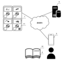
- FIG. 1 is a schematic diagram of an article supply system according to this embodiment.
- 1 is an article supply apparatus of company X
- 2 is an article supplied by the article supply apparatus 1
- 3 is a user's terminal
- 4 is a product of company Y.
- FIG. 1 is an article supply apparatus of company X
- 2 is an article supplied by the article supply apparatus 1
- 3 is a user's terminal
- 4 is a product of company Y.
- the article supply device 1 is a device that supplies articles 2 to the user.
- the article supply device 1 is installed indoors or outdoors, and usually a plurality of article supply devices 1 for supplying different articles are installed.
- the first identification information 11 is displayed on the article supply device 1 that supplies the article 2 .
- This first identification information 11 includes unique identification information that can identify each article supply device 1 .
- the first identification information 11 is the manufacturing number of the article supply device 1 or the like.
- the first identification information 11 is desirably an information display that can be read by the terminal 2 in consideration of user's convenience.
- the information display is a one-dimensional or two-dimensional bar code (QR code: registered trademark).
- the terminal 3 has a reader function for information displays and a communication function with other devices.
- the terminal 3 is, for example, a personal computer, a tablet computer, a smart phone, a mobile phone, or the like.
- Product 4 is a product that company Y supplies to users.
- the type of product does not matter. Examples of products include books such as magazines, foodstuffs such as drinking water, and stationery.
- the article will be described as a magazine.
- the user purchases the magazine (product 4) the user can obtain the right to acquire the product 2.
- FIG. The second identification information 12 is displayed on the magazine (product 4).
- This second identification information 12 is information for authenticating the user's article acquisition right in order to present (supply) the article 2 to the user who has purchased the magazine (product 4).
- the second identification information 12 is a unique serial code or the like that differs for each magazine.
- the article supply device 1 capable of supplying the article 2 and to authenticate the user's right to acquire the article 2 in a place where a plurality of article supply apparatuses 1 are installed. Under these conditions, the article supply device 1 must be in a state in which the articles 2 can be supplied to the user.
- the present embodiment has the following features.
- the first identification information 11 is displayed on the item supply device 1 for specifying the item supply device 1 that can supply the item 2 to the user as a trigger for the user to acquire the item to be presented.
- the first identification information 11 acquired by the terminal 3 is unlocked to supply the article supply device 1, and the article supply device 1 supplies the article to the user.
- the first identification information 11 includes link information for linking to a means for obtaining the second identification information 12 (for example, an input screen for inputting the second identification information 12). include. Thereby, the first identification information 11 read by the terminal 3 can be passed to the means for authenticating the second identification information 12, and the first identification information 11 and the second identification information 12 can be linked.
- the terminal 3 can be the e-book reader.
- the second identification information 12 is included in the e-book itself and a function to read the first identification information 11 is provided, the first identification information 11 and the second identification information 12 can be linked. can.
- the management device that can communicate with the terminal 3 acquires the first identification information 11 and the second identification information 12, and the first identification A method of determining whether or not the article supply device 1 can supply the article 2 based on the information 11 (including specifying the article supply device 1) and authenticating the second identification information 12 can be considered.
- the management apparatus that performed the determination of the first identification information 11 and the authentication of the second identification information 12 is the article supply apparatus specified by the first identification information 11. 1 to transmit an unlock signal for unlocking the supply unit. Then, the supply unit of the article supply device 1 that has received the unlock signal releases the lock and makes it possible to supply the article 2 to the user.
- the management device may be on a network capable of communicating with the article supply device 1, or may be provided in the article supply device 1 itself.
- the terminal 3 receives the determination and authentication completion information from the management device, and the terminal 3 transmits an unlock signal to the article supply device 1. You can make it work.
- the goods supply system according to the first embodiment is a system that realizes collaboration (joint planning) beneficial to both company X that supplies goods to users and company Y that supplies goods to users.
- Company Y has the advantage of having many users purchase its products. Therefore, if a user finds the goods of company X attractive and purchases the goods of company Y because he or she wants to obtain the goods, many users will purchase the company's own goods. has advantages.
- FIG. 2 is a schematic diagram of the article supply system in the first embodiment.
- the same numbers are attached to the same configurations as in FIG.
- the article supply device 1, the user's terminal 2, and the management device 5 are connected to the communication network 6 and can communicate with each other.
- the communication network 6 means a communication path through which data communication is possible. That is, the communication network 6 includes a dedicated line (dedicated cable) for connection, a LAN such as Ethernet (registered trademark), a telephone communication network, a cable network, and a communication network such as the Internet. Any wireless.
- the article supply device 1 is a device that supplies the article 2 to be presented to the user who purchased the magazine 4.
- the terminal 3 is, for example, a personal computer, a tablet computer, a smart phone, a mobile phone, or the like.
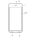
- FIG. 3 is a diagram showing a device configuration example of a smartphone, which is an example of the terminal 3.
- the terminal 3 includes a display 31, a touch operation panel 32 integrated with the display 31, and a built-in speaker 33 and camera .
- the terminal 3 is provided with a control board, an internal battery, a power button, a volume control button, etc., which are not shown.
- control board Various microprocessors such as a CPU, GPU, and DSP, various IC memories such as ASIC, VRAM, RAM, and ROM, and a wireless communication module for wirelessly communicating with a mobile phone base station are mounted on the control board. Also, the control board is equipped with a so-called I/F circuit (interface circuit) such as a driver circuit for the touch operation panel 32 . Each element mounted on these control boards is electrically connected to each other via a bus circuit or the like, and is connected so as to be able to read/write data and transmit/receive signals.
- I/F circuit interface circuit
- Magazine 4 is a product that company Y supplies (sells) to users.
- the serial code for authenticating the user's right to acquire the article 2 (article acquisition right) is written on the magazine 4 in order to present (supply) the article 2 to the user who purchased the magazine 4.
- This serial code is a unique serial code or the like that differs for each of the four magazines. Such a serial code can be generated using check digits or the like.
- the management device 5 is a server system configured including one or more server devices, storage devices, and the like.
- the management device 5 performs processes such as identification of the article supply device 1 that supplies articles, authentication of the second identification information 12, unlocking of the article supply device 1, and the like.
- FIG. 4 is a front view of an example of the article supply device 1
- FIG. 5 is a perspective view of an example of the article supply device 1
- FIG. 6 is a functional block diagram of the article supply device 1.
- the article supply device 1 is a device that supplies articles 2.
- Item 2 is an item targeted for collaboration between Company X and Company Y. By purchasing the magazine 4 of the company Y, the user can obtain the right to acquire the goods 2 supplied by the company X (the goods 2 can be obtained free of charge).
- the article 2 includes, for example, a separable spherical capsule containing a toy or the like, and a toy and a capsule integrated together.
- the article 2 is not limited to one type of article, and may include a plurality of types of articles. In this case, a plurality of types of articles are mixedly accommodated in the article accommodating section 20 of the article supply device 1 described later as articles belonging to one series (type).
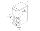
- the front surface of the article supply device 1 has a display 13 displaying the contents of the articles 2, an insertion slot 14 for coins to be paid as the price of the articles 2, a handle 15 as an operation unit, and an outlet through which the articles 2 are supplied. 16 and a coin return port 17 are provided.
- the first identification information 11 (information display: QR code) is displayed on the front surface of the article supply device 1.
- the first identification information 11 is unique article supply apparatus identification information (apparatus ID) for identifying the article supply apparatus 1 and link information to a page for authenticating the second identification information 12 described in the magazine 4.
- URL Uniform Resource Locator
- the first identification information 11 includes other information such as position information for identifying the place where the article supply device 1 is installed, the name of the store, information such as the price of the article, and information on the article supply device. 1 may also include management information necessary to manage the .
- the method of displaying the first identification information 11 in this example, a method of displaying a QR code as an information display by attaching it to the front surface of the article supply device 1 is adopted, but the method is not limited to this.
- the article supply device 1 has a display section such as a liquid crystal
- the information display body of the first identification information 11 may be displayed on the display section.
- the position where the first identification information 11 is displayed is not limited to the front surface of the article supply device 1 .
- it may be displayed near the return port 17 at a position where the bottom surface of the return port 17 can be visually recognized.
- a user who has the article acquisition right can acquire the article 2 free of charge.
- the article supply device 1 includes an article container 20 , an article supply section 21 , a lock section 22 , an operation section 23 , a control section 24 and a communication section 25 .
- the article storage section 20 accommodates a large number of articles 2. Articles can be easily accommodated by pulling the article accommodating section 20 forward and inserting the articles 2 from the front side of the article supply device 1 .
- An article supply section 21 having a rotating disk having a hole large enough for one article 2 to pass through is installed in the lower part of the article storage section 20 .
- the operation unit 23 transmits the operation of the handle 15 to the rotating disk of the article supply unit 21.
- the operating portion 23 is locked by the locking portion 22, and unlocking allows the handle 15 to be rotated by the user's operation.
- the unlocking mechanism for example, an unlocking mechanism using a solenoid lock is used.
- a solenoid lock is used to put the handle 15 in a non-rotatable state (locked state), and the solenoid is energized to release the lock and make the handle 15 rotatable.
- the unlocking mechanism is not limited to a solenoid lock, and other unlocking mechanisms may be used.
- the handle 15 When the lock portion 22 is in the unlocked state, the handle 15 is rotated by a predetermined angle to rotate the turntable, and the hole of the turntable and the drop opening provided at the bottom of the article storage portion 20 face each other. Then, one article 2 is supplied from the drop port to the outlet 16 through a passage communicating with the outlet 16 .
- the control section 24 controls locking and unlocking of the lock section 22 .
- the lock release of the lock unit 22 by the control unit 24 is performed by settlement with cash inserted into the insertion port 14 or by an unlock signal controlled from the outside.
- the control unit 24 locks the lock unit 22 after detecting that the articles 2 have been discharged to the outlet 16 or after a predetermined time has elapsed after unlocking.
- the control section 24 may lock the lock section 22 by a lock signal controlled from the outside.
- the communication unit 25 can communicate with the management device 5 via the communication network 6.
- FIG. 7 is a block diagram showing an example of the functional configuration of the terminal 3.
- the terminal 3 includes an operation input unit 301, an imaging unit 302, a processing unit 303, an image display unit 304, a sound output unit 305, a communication unit 306, and a storage unit 307. .
- the operation input unit 301 is for inputting various user operations, and outputs an operation input signal corresponding to the operation input to the processing unit 303 .
- the functions of the operation input unit 301 include, for example, elements such as a touch operation pad, home button, button switch, joystick, and trackball that are directly operated by the user with a finger, as well as acceleration sensors, angular velocity sensors, tilt sensors, and geomagnetic sensors. It can also be realized by an element or the like that detects motion or posture. In FIG. 3, the touch operation panel 32 corresponds to this.
- the photographing unit 302 performs photographing processing of the information display body (QR code) of the first identification information 11 and outputs the photographed image to the processing unit 303 .
- the imaging unit 302 includes a lens, an imaging device, and a controller that controls them. In FIG. 3, the camera 34 corresponds to this.
- the processing unit 303 comprehensively controls operations of the terminal 3 based on programs and data stored in the storage unit 307, operation input signals from the operation input unit 301, and the like.
- the functions of the processing unit 303 can be realized by, for example, electronic components such as microprocessors such as CPUs and GPUs, ASICs, and IC memories.
- the processing unit 303 includes a calculation unit 51, an image generation unit 52, a sound generation unit 53, and a communication control unit 54 as main functional units.
- the calculation unit 51 outputs to the image generation unit 52, the sound generation unit 53, and the communication control unit 54.
- the calculation unit 51 includes an information display body acquisition unit 510 , a serial code acquisition unit 511 , and a supply information guidance unit 512 .
- the information display body acquisition unit 510 reads the information display body of the article supply device 1 captured by the imaging unit 302 and acquires the first identification information 11 .
- the serial code acquiring section 511 transmits a request for transmitting a serial code input screen including the acquired device ID.
- the destination (link destination) of this request is the management device 5 .
- the serial code input screen is received, and the serial code input screen is displayed on the image display section 304 via the image generation section 52 . Also, the serial code input on the serial code input screen is transmitted to the management device 5 .
- the supply information guidance unit 512 allows the management device 5 to display the authentication result of the serial code, the guidance regarding the supply of goods, and the guidance regarding an error (impossible to supply) on the image display unit 304 via the image generation unit 52 . do.
- the functions of the information display body acquisition unit 510, the serial code acquisition unit 511, and the supply information guide unit 512 can be realized by a web browser installed in the terminal 3. But it can be done.
- the image generation unit 52 generates one image in one frame time (for example, 1/60 second) based on the processing result of the calculation unit 51 and outputs the generated image signal to the image display unit 304 .
- the functions of the image generator 52 are, for example, a processor such as a GPU or a digital signal processor (DSP), a video signal IC, a program such as a video codec, an IC memory for drawing frames such as a frame buffer, and texture data development. It can be realized by an IC memory or the like.
- the sound generation unit 53 generates sound signals such as sound effects and various operation sounds based on the processing result of the calculation unit 51 and outputs them to the sound output unit 305 .
- the function of the sound generator 53 can be realized by, for example, a digital signal processor (DSP), a processor such as a voice synthesis IC, an audio codec capable of reproducing voice files, or the like.
- DSP digital signal processor
- a processor such as a voice synthesis IC, an audio codec capable of reproducing voice files, or the like.
- the communication control unit 54 performs communication connection and data processing for data communication with the management device 5 and the like.
- the image display unit 304 displays a screen based on the image signal input from the image generation unit 52.
- the function of the image display unit 304 can be realized by a display device such as a flat panel display, a cathode ray tube (CRT), a projector, or a head mounted display.
- the image display unit 304 corresponds to the display 31 in FIG.
- the sound output unit 305 is for outputting sound effects and the like based on the sound signal input from the sound generation unit 53 .
- the sound output unit 203 corresponds to the speaker 33 in FIG.
- the communication unit 306 is connected to the communication line N to realize communication.
- the function of the communication unit 306 can be realized by, for example, a wireless communication device, a modem, a TA (terminal adapter), a wired communication cable jack, a control circuit, or the like.
- the storage unit 307 a program for operating the terminal 3 and realizing various functions of the terminal 3, data used during the execution of the program, etc. are stored in advance, or temporarily stored each time processing is performed. remembered.
- the storage unit 307 can be realized by, for example, a RAM, a ROM, an IC memory such as a flash memory, a magnetic disk such as a hard disk, an optical disk such as a CD-ROM or a DVD, or the like.
- the storage unit 307 stores a system program and a control program.
- the system program is a program for realizing the basic functions of the terminal 3 as a computer.
- the control program is a program for functioning as the calculation section 51 (the information display body acquisition section 510, the serial code acquisition section 511, the supply information guide section 512) of the processing section 31.
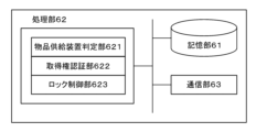
- FIG. 8 is a block diagram showing a functional configuration example of the management device 5. As shown in FIG.
- the management device 5 includes a storage section 61 , a processing section 62 and a communication section 63 .
- the storage unit 61 is realized by, for example, RAM, ROM, IC memory such as flash memory, magnetic disk such as hard disk, optical disk such as CD-ROM and DVD, etc., and stores system programs and function programs.
- a system program is a program for realizing the basic functions of a computer.
- the function program is a program for causing the processing section 62 to function as an article supply device determination section 621, an acquisition right authentication section 622, and a lock control section 623, which will be described later. It also stores article supply device data D1 and serial code data D2, which will be described later.
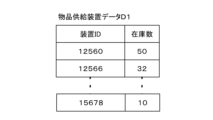
- the product supply device data D1 stores the device ID of the product supply device 1 capable of supplying the product 2 that is the target of collaboration between company X and company Y, and the number of products in stock of the product supply device 1.
- FIG. 9 is a diagram showing an example of the article supply device data D1.
- the article supply device data D1 includes the device ID of the article supply device 1 capable of supplying the article 2 to be collaborated between the company X and the company Y, and the article supply device 1 having the device ID. are stored in association with the number of items in stock.
- the serial code data D2 is the serial code written in the magazine 4 sold by company Y.
- the serial code is a unique code number assigned to each magazine 4 and not duplicated. Such a serial code can be generated using check digits or the like.
- FIG. 10 is a diagram showing an example of the serial code data D2. As shown in FIG. 10, the serial code data D2 is stored in association with a unique serial code and an authentication flag. As will be described later, when the acquisition right authentication unit 622 authenticates the user's right to acquire an article using the serial code, and the supply of the article 2 from the article supply device 1 is completed, the authentication flag field of the serial code indicates that the authentication has been completed. An authenticated flag indicating that is given.
- the processing unit 62 comprehensively controls the operation of the management device 5 based on the programs and data stored in the storage unit 61 .
- the functions of the processing unit 62 can be realized by, for example, electronic components such as microprocessors such as CPUs and GPUs, ASICs, and IC memories.
- the processing unit 62 includes an article supply device determination unit 621, an acquisition right authentication unit 622, and a lock control unit 623 as main functional units.
- the article supply device determination unit 621 receives the serial code input screen request from the terminal 3, acquires the device ID included in the request, and determines whether the acquired device ID is included in the article supply device data D1. to judge. If it is included in the article supply device data D1, the article supply device determination unit 621 confirms the inventory quantity of the article supply device 1 with that device ID, and if there is an inventory quantity, the article supply device with the device ID acquired by the user is confirmed. It is determined that the device 1 is an article supply device 1 capable of supplying an article 2 to be collaborated with a magazine 4 . Then, the article supply device determining section 621 identifies the article supply device 1 to which the lock release signal is to be sent.
- the article supply device determination section 621 transmits a serial code input screen to the terminal 3 .
- the article supply device determination unit 621 determines that the article 2 cannot be supplied. to the terminal 3. It should be noted that the period during which the article 2 can be supplied from the article supply apparatus 1 is predetermined, and even if the request for the serial code input screen is received from the terminal 3 after the lapse of the period during which the article can be supplied, the article 2 cannot be supplied. An error screen is sent to the terminal 3 to guide that the supply is impossible.
- the acquisition right authentication unit 622 checks the serial code input on the input screen against the serial code of the serial code data D2, and determines that the serial code input on the input screen is included in the serial code data D2, and If the serial code has no authentication flag, it is assumed that the serial code entered on the input screen has been authenticated and that the user's right to acquire the article has been authenticated. Then, guidance information for guiding the supply of goods is transmitted to the terminal 3 of the user. If the serial code has an expiration date set, the acquisition right authentication unit 622 also authenticates the expiration date of the serial code entered on the input screen.
- the acquisition right authentication unit 622 generates an error message indicating that the serial code (goods acquisition right) could not be authenticated. Send the screen to terminal 3.
- the lock control unit 623 determines that the article supply device 1 with the device ID can supply the article 2 by the article supply device determination unit 621, and when the acquisition right authentication unit 622 authenticates the article acquisition right, the lock control unit 623 determines that the acquired device ID A lock release signal is transmitted to the article supply device 1 .
- FIG. 11 is a sequence diagram of the article supply system of this embodiment
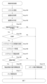
- FIG. 12 is a flow chart of the management device 5 of this embodiment
- FIG. 13 is a flow chart of the article supply device 1 of this embodiment.
- the article supply device data D1 is shown in FIG. 9 and the serial code data D2 is shown in FIG.
- FIG. 14 is a diagram showing an example of photographing of the information display body of the first identification information 11 of the article supply device 1 by the photographing unit 302 of the terminal 3. As shown in FIG. The user stands in front of the article supply device 1, operates the terminal 3 so that the information display body of the first identification information 11 is displayed on the display 31 of the terminal 3, and photographs the information display body.
- the information acquisition unit 510 of the terminal 3 acquires the first identification information 11 from the imaged information display body of the first identification information 11 .
- the acquired first identification information 11 includes the device ID of the article supply device 1 and is link destination information (for example, URL) to means for authenticating the serial code 12 (Step 2).
- link destination information for example, URL
- the serial code acquisition unit 511 of the terminal 3 transmits a request to the management device 5 to request transmission of the serial code input screen based on the link destination including the device ID of the article supply device 1 (Step 3).
- the management device 5 receives the request from the terminal and performs supply determination processing (Step 4). Details of the supply determination process will be described later.
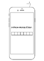
- the serial code acquisition unit 511 of the terminal 3 displays the serial code input screen (Step 5).
- FIG. 15 is an example of a serial code input screen displayed on the terminal 3.
- the user inputs the serial code on the displayed input screen (Step 6). In this example, it is assumed that the user has entered the serial code "1VB3588" into the serial code input screen.
- the serial code acquisition unit 511 then transmits the serial code to the management device 5 .
- the management device 5 receives the serial code and performs supply determination processing (Step 4).
- the management device 5 transmits guidance information to the terminal 3 when the serial code can be authenticated.
- the management device 5 transmits an unlock signal to the article supply device 1 (Step 4).
- the supply information guidance unit 512 of the terminal 3 receives the guidance information from the management device 5 and displays the guidance information (Step 8).
- FIG. 16 shows an example of guidance information displayed on the terminal 3.
- the guide information in FIG. 16 guides that the serial code is authenticated, that the handle 15 of the article supply device 1 is operated to receive the article, and that the handle 15 is locked in one minute. The user operates the article supply device 1 according to the guidance information.
- the article supply device 1 receives the unlock signal and performs supply processing (Step 9). The article supply device 1 then transmits a supply report to the management device 5 . Details of the supply process (Step 9) will be described later.
- the acquisition right authentication unit 622 of the management device 5 receives the supply report, and if the supply report is a report that the article has been supplied normally, the authentication flag field of the corresponding serial code in the serial code data D2 indicates that authentication has been completed. An authenticated flag indicating that the serial code cannot be used again is given (Step 10). Also, the inventory quantity of the article supply device 1 that has sent the supply report is decremented by one. The above is the description of the overall operation.
- Step 4 the supply determination process (Step 4) of the management device 5 will be described using the flowchart of FIG.
- the article supply device determination unit 621 of the management device 5 Upon receiving the request from the terminal 3 (Step 100), the article supply device determination unit 621 of the management device 5 acquires the device ID included in the request (Step 101).
- the acquired device ID is "12560".
- the article supply device determination unit 621 uses the article supply device data D1 to determine the device ID (Step 102). Determination of the device ID is determination as to whether the acquired device ID is included in the article supply device data D1. If the acquired device ID is included in the article supply device data D1 (Step 103), the article supply device 1 having the device ID acquired by the user can supply the article 2 to be collaborated with the magazine 4. The article supply device 1 that is determined to be the device 1 and that transmits the unlock signal is specified. On the other hand, if the acquired device ID is not included in the article supply device data D1 (Step 103), the article supply device 1 having the device ID acquired by the user can supply the article 2 to be collaborated with the magazine 4.
- FIG. 19 is a diagram showing an example of guide information for an error in the article supply device.
- the acquired device ID is "12560" and is included in the article supply device data D1. 2 is determined to be the article supplying apparatus 1 capable of supplying the article.
- the article supply device determination unit 621 checks the inventory of the article 2 of the article supply device 1 with the acquired device ID (Step 104).
- the article supply device determination unit 621 determines that the article supply device 1 of the acquired device ID can supply the article 2, and unlocks it.
- the article supply device 1 to which the signal is to be sent is specified.
- the article supply device determining section 621 transmits the serial code input screen to the terminal 3 (Step 105).
- the article supply device determination section 621 transmits error guide information to the terminal 3 (Step 110).
- error guide information as shown in FIG. 19 is transmitted to the terminal 3 .
- the stock quantity of the article supply device 1 with the device ID "12560" obtained in the article supply device data D1 is not "0", so the serial code input screen is sent to the terminal 3 (Step 105).
- the acquisition right authentication unit 622 receives the serial code entered on the input screen (Step 106), it authenticates the acquired serial code (Step 107).
- the obtained serial code is "1VB3588", and the serial code "1VB3588" is to be authenticated.
- the acquisition right authentication unit 622 collates the acquired serial code with the serial code of the serial code data D2, and determines that the acquired serial code is included in the serial code data D2 and that the serial code has an authenticated flag. If not, the acquired serial code is authenticated, and it is determined that the user's right to acquire the article 2 has been authenticated (Step 108). If the serial code has an expiration date set, the acquisition right authentication unit 622 also authenticates the expiration date of the serial code entered on the input screen. If the expiration date of the serial code is valid and the serial code is authenticated, the acquisition right authentication unit 622 transmits guide information regarding the supply of goods (Step 109).
- the acquisition right authentication unit 622 collates the acquired serial code with the serial code of the serial code data D2, and finds that the acquired serial code is not included in the serial code data D2 or the acquired serial code is a serial code. Even if it is included in data D2, if the serial code has an authenticated flag, the serial code has an expiration date, and if the expiration date has passed, the acquired serial code is inappropriate. not authenticated. If the serial code cannot be authenticated (including cases where the serial code has expired and cannot be authenticated), the acquisition right authentication unit 622 displays an error screen that informs that the serial code (goods acquisition right) could not be authenticated. It is transmitted to the terminal 3 (Step 110). FIG. 20 is an example of an error screen that informs that the serial code could not be authenticated.
- the acquired serial code is "1VB3588", which is included in the serial code data D2 and has no authenticated flag. Also, the serial code does not have an expiration date. Therefore, the acquisition right authentication unit 622 determines that the acquired serial code "1VB3588" is authenticated and that the user's right to acquire the article 2 is authenticated, and transmits guide information regarding the supply of the article.
- the lock control section 623 An unlock signal is transmitted to the article supply device 1 having the device ID specified by 621 (Step 111).
- the lock control unit 623 transmits an unlock signal to the article supply device 1 with the device ID "12560".
- the description of the supply determination process (Step 4) of the management device 5 ends here.
- Step 9 the supply processing (Step 9) of the article supply device 1 will be described with reference to the flowchart of FIG.
- the control section 24 of the article supply device 1 unlocks the lock section 22 (Step 201).
- the control unit 24 of the article supply device 1 determines whether the article 2 is supplied (Step 202). First, the control unit 24 determines whether the handle 15 of the operation unit 23 has been operated (for example, rotated once) (Step 203). When the handle 15 is operated (for example, rotated once), one article 2 is supplied from the article supply section 21 to the outlet 16 (Step 204). Then, the control unit 24 locks the lock unit 22 (Step 205).
- Step 203 the control unit 24 determines whether a predetermined time (for example, 1 minute) has elapsed since unlocking (Step 207).
- a predetermined time for example, 1 minute
- a predetermined time for example, one minute
- control unit 24 makes a supply report to the effect that the article 2 has been supplied normally if the article 2 has been supplied normally, and if the article 2 has not been supplied, the article 2 has not been supplied. A supply report to that effect is made (Step 206).
- the control unit 24 determines whether a predetermined time has passed since unlocking, and if the predetermined time has passed, the lock unit 22 is unlocked.
- An example of locking is explained. This is just an example.
- the lock control unit 623 of the management device 5 measures the time from the transmission of the lock release signal, and reports that the article 2 has been normally supplied before a predetermined time elapses. If not received, the control section 24 may be configured to transmit a lock signal to the control section 24 of the article supply device 1 . In this case, when the control unit 24 receives the lock signal, the control unit 24 brings the lock unit 22 into the locked state. This completes the description of the supply processing (Step 9) of the article supply device 1.
- the article supply device 1 when a supply period in which the article supply device 1 can supply the gift 2 is set, and the article 2 is obtained after that, or when the location where the article supply device 1 is installed is remote from the user.
- the article 2 may be delivered to the user without going to the article supply device 1 on condition that the serial code is authenticated upon application by the user.
- the first identification information 11 is displayed on the article supply device 1 for specifying the article supply device capable of supplying the article to the user as a trigger for the user to acquire the article to be presented. Therefore, the user goes to the place where the article supply device 1 displaying the first identification information 11 is installed. As a result, the user is guided to the place where the article supply device 1 is installed, so that the user can know the article supply device that supplies other articles. Also, the user can know that various items are being supplied in addition to the supplied items. Furthermore, this embodiment allows authentication of the second identification information 11 described in the magazine 4 at the place where the first identification information 11 is obtained, taking user convenience into consideration. On the other hand, for a company that provides products such as magazines, by giving the product as a gift, users will be more motivated to purchase the product.
- the present embodiment realizes a collaboration (joint planning) that is beneficial not only to the user to whom the goods are supplied, but also to both the company that supplies the goods to the user and the company that supplies the goods to the user. can be done.
- the present embodiment can meet the needs of various consumers such as companies that intend to use the article supply apparatus as well as users to whom articles are supplied.
- the present invention is not limited to this.
- the user's action to acquire the article acquisition right may be participation in an event
- the second identification information 12 may be a serial code given by participation in the event.
- the action of the user who acquires the article acquisition right may be an application for a lottery
- the second identification information 12 may be a serial code given by winning the lottery.
- FIG. 17 is a diagram for explaining the article supply device 1 of the second embodiment.
- the article supply apparatus 1 of the first embodiment is made to function as one unit, and one article supply apparatus 1 is configured from a plurality of units 70 and one display unit 71. explain.
- the unit 70 is similar to the article supply device 1 described in the first embodiment. Differences from the article supply apparatus 1 described in the first embodiment are as follows. - The first identification information 11 is not displayed (mounted) on the unit 70 .
- the unit 70 comprises a light-emitting element 72 such as an LED that is visible to the user.
- the control section 24 lights up the light emitting element 72 to inform the user that the unit 70 can supply the article 2.
- the display unit 71 is installed at the top of the plurality of units 70, and the first identification information 11 is displayed.
- the first identification information 11 is not the device ID of each unit 70 but the device ID of one article supply device 1 (hereinafter referred to as group ID) in which a plurality of units 70 are grouped. Further, the display unit 71 displays that the unit 70 whose light-emitting element 72 is lit among the plurality of units 70 can supply the article 2 .
- the configuration of the article supply device data D1 and the configuration of the article supply device determination section 621 are different.
- the article supply device data D1 similarly stores the device ID of the unit 70 and the stock quantity of the article 2 of the unit 70, but these are group IDs of a plurality of units 70 grouped together. is associated with a group ID that is This group ID is the group ID included in the first identification information 11 displayed on the display unit 71 .
- FIG. 18 shows an example of article supply device data D1 according to the second embodiment.
- device IDs of a plurality of units 70 are associated with one group ID "101". That is, the units 70 having a plurality of device IDs belonging to the group ID "101" configure one article supply device 1.
- the article supply device determination unit 621 receives the request for the input screen of the serial code from the terminal 3, acquires the group ID included in the request instead of the device ID, and uses the acquired group ID as the article supply device data. Determine if it is included in D1.
- the unit 70 having the device ID in which the article 2 is in stock is specified among the device IDs belonging to the group ID acquired by the user.
- the simplest method for specifying the unit 70 of the device ID is to search the stock quantity in the order of the smallest device ID among the device IDs belonging to the group ID, and supply the unit 70 of the device ID that is in stock and the article 2. This is a method of specifying that the unit 70 is a valid unit 70 .
- the unit 70 of the device ID may be specified so that the stock quantity is uniform.
- the article supply device determination section 621 transmits an unlock signal to the unit 70 having the specified device ID.
- the control section 24 of the unit 70 unlocks the lock section 22 .
- Other configurations and operations are similar to those of the first embodiment.
- the second embodiment has the following effects in addition to the effects of the first embodiment.
- the management device 5 selects and unlocks the unit 70 with the number of stocks, after obtaining the first identification information of the user, an error due to lack of stock is prevented, and the first identification by the user is prevented. Acquisition of information can be avoided, and the user's convenience is enhanced.
- the management side of the article supply device does not need to display or attach the first identification information to each unit 70, and only needs to display one piece of first identification information on the display unit 71.
- the burden on the side managing the supply device is reduced.
- the number of pieces of first identification information to be displayed on the display unit 71 is not necessarily limited to one, and may be plural if necessary.
Landscapes
- Physics & Mathematics (AREA)
- General Physics & Mathematics (AREA)
- Control Of Vending Devices And Auxiliary Devices For Vending Devices (AREA)
- Vending Machines For Individual Products (AREA)
- Management, Administration, Business Operations System, And Electronic Commerce (AREA)
Priority Applications (1)
| Application Number | Priority Date | Filing Date | Title |
|---|---|---|---|
| CN202280049803.9A CN117751395A (zh) | 2021-08-03 | 2022-08-02 | 物品供给装置、物品供给系统以及管理装置 |
Applications Claiming Priority (2)
| Application Number | Priority Date | Filing Date | Title |
|---|---|---|---|
| JP2021-127831 | 2021-08-03 | ||
| JP2021127831A JP7082767B1 (ja) | 2021-08-03 | 2021-08-03 | 物品供給装置、物品供給システム及び管理装置 |
Publications (1)
| Publication Number | Publication Date |
|---|---|
| WO2023013648A1 true WO2023013648A1 (ja) | 2023-02-09 |
Family
ID=81940894
Family Applications (1)
| Application Number | Title | Priority Date | Filing Date |
|---|---|---|---|
| PCT/JP2022/029684 Ceased WO2023013648A1 (ja) | 2021-08-03 | 2022-08-02 | 物品供給装置、物品供給システム及び管理装置 |
Country Status (3)
| Country | Link |
|---|---|
| JP (2) | JP7082767B1 (https=) |
| CN (1) | CN117751395A (https=) |
| WO (1) | WO2023013648A1 (https=) |
Citations (2)
| Publication number | Priority date | Publication date | Assignee | Title |
|---|---|---|---|---|
| JP2004334911A (ja) * | 2004-07-28 | 2004-11-25 | Bandai Co Ltd | 物品取出装置 |
| JP2020077342A (ja) * | 2018-11-09 | 2020-05-21 | 株式会社ウイルコホールディングス | 自動物品提供システム及び自動物品提供方法 |
-
2021
- 2021-08-03 JP JP2021127831A patent/JP7082767B1/ja active Active
-
2022
- 2022-05-18 JP JP2022081849A patent/JP7705363B2/ja active Active
- 2022-08-02 CN CN202280049803.9A patent/CN117751395A/zh active Pending
- 2022-08-02 WO PCT/JP2022/029684 patent/WO2023013648A1/ja not_active Ceased
Patent Citations (2)
| Publication number | Priority date | Publication date | Assignee | Title |
|---|---|---|---|---|
| JP2004334911A (ja) * | 2004-07-28 | 2004-11-25 | Bandai Co Ltd | 物品取出装置 |
| JP2020077342A (ja) * | 2018-11-09 | 2020-05-21 | 株式会社ウイルコホールディングス | 自動物品提供システム及び自動物品提供方法 |
Also Published As
| Publication number | Publication date |
|---|---|
| JP7082767B1 (ja) | 2022-06-09 |
| CN117751395A (zh) | 2024-03-22 |
| JP2023022811A (ja) | 2023-02-15 |
| JP7705363B2 (ja) | 2025-07-09 |
| JP2023022771A (ja) | 2023-02-15 |
Similar Documents
| Publication | Publication Date | Title |
|---|---|---|
| JP2026066396A (ja) | 物品供給装置及び物品供給システム | |
| WO2023032897A1 (ja) | 物品供給装置、物品供給システム及び管理装置 | |
| JP2026021617A (ja) | 物品供給装置、物品供給システム、管理装置及び物品供給方法 | |
| WO2023013648A1 (ja) | 物品供給装置、物品供給システム及び管理装置 | |
| JP7836277B2 (ja) | 物品供給装置 | |
| CN118155344B (zh) | 用于物品提供的程序产品、终端以及管理装置 | |
| JP7775360B2 (ja) | 物品供給装置、物品供給システム及び管理装置 | |
| US20260044875A1 (en) | Program, terminal, article supply apparatus, and management apparatus | |
| KR102955125B1 (ko) | 물품 공급 장치 및 물품 공급 시스템 |
Legal Events
| Date | Code | Title | Description |
|---|---|---|---|
| 121 | Ep: the epo has been informed by wipo that ep was designated in this application |
Ref document number: 22853067 Country of ref document: EP Kind code of ref document: A1 |
|
| WWE | Wipo information: entry into national phase |
Ref document number: 202280049803.9 Country of ref document: CN |
|
| NENP | Non-entry into the national phase |
Ref country code: DE |
|
| 122 | Ep: pct application non-entry in european phase |
Ref document number: 22853067 Country of ref document: EP Kind code of ref document: A1 |