WO2023013447A1 - カテーテルの製造方法およびカテーテルの製造装置 - Google Patents
カテーテルの製造方法およびカテーテルの製造装置 Download PDFInfo
- Publication number
- WO2023013447A1 WO2023013447A1 PCT/JP2022/028476 JP2022028476W WO2023013447A1 WO 2023013447 A1 WO2023013447 A1 WO 2023013447A1 JP 2022028476 W JP2022028476 W JP 2022028476W WO 2023013447 A1 WO2023013447 A1 WO 2023013447A1
- Authority
- WO
- WIPO (PCT)
- Prior art keywords
- elastic body
- hard part
- catheter
- manufacturing
- external force
- Prior art date
- Legal status (The legal status is an assumption and is not a legal conclusion. Google has not performed a legal analysis and makes no representation as to the accuracy of the status listed.)
- Ceased
Links
Images













Classifications
-
- A—HUMAN NECESSITIES
- A61—MEDICAL OR VETERINARY SCIENCE; HYGIENE
- A61M—DEVICES FOR INTRODUCING MEDIA INTO, OR ONTO, THE BODY; DEVICES FOR TRANSDUCING BODY MEDIA OR FOR TAKING MEDIA FROM THE BODY; DEVICES FOR PRODUCING OR ENDING SLEEP OR STUPOR
- A61M25/00—Catheters; Hollow probes
- A61M25/0009—Making of catheters or other medical or surgical tubes
-
- B—PERFORMING OPERATIONS; TRANSPORTING
- B29—WORKING OF PLASTICS; WORKING OF SUBSTANCES IN A PLASTIC STATE IN GENERAL
- B29C—SHAPING OR JOINING OF PLASTICS; SHAPING OF MATERIAL IN A PLASTIC STATE, NOT OTHERWISE PROVIDED FOR; AFTER-TREATMENT OF THE SHAPED PRODUCTS, e.g. REPAIRING
- B29C65/00—Joining or sealing of preformed parts, e.g. welding of plastics materials; Apparatus therefor
- B29C65/02—Joining or sealing of preformed parts, e.g. welding of plastics materials; Apparatus therefor by heating, with or without pressure
- B29C65/14—Joining or sealing of preformed parts, e.g. welding of plastics materials; Apparatus therefor by heating, with or without pressure using wave energy, i.e. electromagnetic radiation, or particle radiation
- B29C65/16—Laser beams
- B29C65/1629—Laser beams characterised by the way of heating the interface
- B29C65/1654—Laser beams characterised by the way of heating the interface scanning at least one of the parts to be joined
-
- B—PERFORMING OPERATIONS; TRANSPORTING
- B29—WORKING OF PLASTICS; WORKING OF SUBSTANCES IN A PLASTIC STATE IN GENERAL
- B29C—SHAPING OR JOINING OF PLASTICS; SHAPING OF MATERIAL IN A PLASTIC STATE, NOT OTHERWISE PROVIDED FOR; AFTER-TREATMENT OF THE SHAPED PRODUCTS, e.g. REPAIRING
- B29C65/00—Joining or sealing of preformed parts, e.g. welding of plastics materials; Apparatus therefor
- B29C65/02—Joining or sealing of preformed parts, e.g. welding of plastics materials; Apparatus therefor by heating, with or without pressure
- B29C65/14—Joining or sealing of preformed parts, e.g. welding of plastics materials; Apparatus therefor by heating, with or without pressure using wave energy, i.e. electromagnetic radiation, or particle radiation
- B29C65/16—Laser beams
- B29C65/1677—Laser beams making use of an absorber or impact modifier
-
- B—PERFORMING OPERATIONS; TRANSPORTING
- B29—WORKING OF PLASTICS; WORKING OF SUBSTANCES IN A PLASTIC STATE IN GENERAL
- B29C—SHAPING OR JOINING OF PLASTICS; SHAPING OF MATERIAL IN A PLASTIC STATE, NOT OTHERWISE PROVIDED FOR; AFTER-TREATMENT OF THE SHAPED PRODUCTS, e.g. REPAIRING
- B29C66/00—General aspects of processes or apparatus for joining preformed parts
- B29C66/01—General aspects dealing with the joint area or with the area to be joined
- B29C66/05—Particular design of joint configurations
- B29C66/10—Particular design of joint configurations particular design of the joint cross-sections
- B29C66/11—Joint cross-sections comprising a single joint-segment, i.e. one of the parts to be joined comprising a single joint-segment in the joint cross-section
- B29C66/112—Single lapped joints
- B29C66/1122—Single lap to lap joints, i.e. overlap joints
-
- B—PERFORMING OPERATIONS; TRANSPORTING
- B29—WORKING OF PLASTICS; WORKING OF SUBSTANCES IN A PLASTIC STATE IN GENERAL
- B29C—SHAPING OR JOINING OF PLASTICS; SHAPING OF MATERIAL IN A PLASTIC STATE, NOT OTHERWISE PROVIDED FOR; AFTER-TREATMENT OF THE SHAPED PRODUCTS, e.g. REPAIRING
- B29C66/00—General aspects of processes or apparatus for joining preformed parts
- B29C66/01—General aspects dealing with the joint area or with the area to be joined
- B29C66/05—Particular design of joint configurations
- B29C66/10—Particular design of joint configurations particular design of the joint cross-sections
- B29C66/11—Joint cross-sections comprising a single joint-segment, i.e. one of the parts to be joined comprising a single joint-segment in the joint cross-section
- B29C66/114—Single butt joints
- B29C66/1142—Single butt to butt joints
-
- B—PERFORMING OPERATIONS; TRANSPORTING
- B29—WORKING OF PLASTICS; WORKING OF SUBSTANCES IN A PLASTIC STATE IN GENERAL
- B29C—SHAPING OR JOINING OF PLASTICS; SHAPING OF MATERIAL IN A PLASTIC STATE, NOT OTHERWISE PROVIDED FOR; AFTER-TREATMENT OF THE SHAPED PRODUCTS, e.g. REPAIRING
- B29C66/00—General aspects of processes or apparatus for joining preformed parts
- B29C66/50—General aspects of joining tubular articles; General aspects of joining long products, i.e. bars or profiled elements; General aspects of joining single elements to tubular articles, hollow articles or bars; General aspects of joining several hollow-preforms to form hollow or tubular articles
- B29C66/51—Joining tubular articles, profiled elements or bars; Joining single elements to tubular articles, hollow articles or bars; Joining several hollow-preforms to form hollow or tubular articles
- B29C66/52—Joining tubular articles, bars or profiled elements
- B29C66/522—Joining tubular articles
- B29C66/5221—Joining tubular articles for forming coaxial connections, i.e. the tubular articles to be joined forming a zero angle relative to each other
-
- B—PERFORMING OPERATIONS; TRANSPORTING
- B29—WORKING OF PLASTICS; WORKING OF SUBSTANCES IN A PLASTIC STATE IN GENERAL
- B29C—SHAPING OR JOINING OF PLASTICS; SHAPING OF MATERIAL IN A PLASTIC STATE, NOT OTHERWISE PROVIDED FOR; AFTER-TREATMENT OF THE SHAPED PRODUCTS, e.g. REPAIRING
- B29C66/00—General aspects of processes or apparatus for joining preformed parts
- B29C66/50—General aspects of joining tubular articles; General aspects of joining long products, i.e. bars or profiled elements; General aspects of joining single elements to tubular articles, hollow articles or bars; General aspects of joining several hollow-preforms to form hollow or tubular articles
- B29C66/63—Internally supporting the article during joining
-
- B—PERFORMING OPERATIONS; TRANSPORTING
- B29—WORKING OF PLASTICS; WORKING OF SUBSTANCES IN A PLASTIC STATE IN GENERAL
- B29C—SHAPING OR JOINING OF PLASTICS; SHAPING OF MATERIAL IN A PLASTIC STATE, NOT OTHERWISE PROVIDED FOR; AFTER-TREATMENT OF THE SHAPED PRODUCTS, e.g. REPAIRING
- B29C66/00—General aspects of processes or apparatus for joining preformed parts
- B29C66/50—General aspects of joining tubular articles; General aspects of joining long products, i.e. bars or profiled elements; General aspects of joining single elements to tubular articles, hollow articles or bars; General aspects of joining several hollow-preforms to form hollow or tubular articles
- B29C66/65—General aspects of joining tubular articles; General aspects of joining long products, i.e. bars or profiled elements; General aspects of joining single elements to tubular articles, hollow articles or bars; General aspects of joining several hollow-preforms to form hollow or tubular articles with a relative motion between the article and the welding tool
-
- B—PERFORMING OPERATIONS; TRANSPORTING
- B29—WORKING OF PLASTICS; WORKING OF SUBSTANCES IN A PLASTIC STATE IN GENERAL
- B29C—SHAPING OR JOINING OF PLASTICS; SHAPING OF MATERIAL IN A PLASTIC STATE, NOT OTHERWISE PROVIDED FOR; AFTER-TREATMENT OF THE SHAPED PRODUCTS, e.g. REPAIRING
- B29C66/00—General aspects of processes or apparatus for joining preformed parts
- B29C66/70—General aspects of processes or apparatus for joining preformed parts characterised by the composition, physical properties or the structure of the material of the parts to be joined; Joining with non-plastics material
- B29C66/73—General aspects of processes or apparatus for joining preformed parts characterised by the composition, physical properties or the structure of the material of the parts to be joined; Joining with non-plastics material characterised by the intensive physical properties of the material of the parts to be joined, by the optical properties of the material of the parts to be joined, by the extensive physical properties of the parts to be joined, by the state of the material of the parts to be joined or by the material of the parts to be joined being a thermoplastic or a thermoset
- B29C66/739—General aspects of processes or apparatus for joining preformed parts characterised by the composition, physical properties or the structure of the material of the parts to be joined; Joining with non-plastics material characterised by the intensive physical properties of the material of the parts to be joined, by the optical properties of the material of the parts to be joined, by the extensive physical properties of the parts to be joined, by the state of the material of the parts to be joined or by the material of the parts to be joined being a thermoplastic or a thermoset characterised by the material of the parts to be joined being a thermoplastic or a thermoset
- B29C66/7392—General aspects of processes or apparatus for joining preformed parts characterised by the composition, physical properties or the structure of the material of the parts to be joined; Joining with non-plastics material characterised by the intensive physical properties of the material of the parts to be joined, by the optical properties of the material of the parts to be joined, by the extensive physical properties of the parts to be joined, by the state of the material of the parts to be joined or by the material of the parts to be joined being a thermoplastic or a thermoset characterised by the material of the parts to be joined being a thermoplastic or a thermoset characterised by the material of at least one of the parts being a thermoplastic
- B29C66/73921—General aspects of processes or apparatus for joining preformed parts characterised by the composition, physical properties or the structure of the material of the parts to be joined; Joining with non-plastics material characterised by the intensive physical properties of the material of the parts to be joined, by the optical properties of the material of the parts to be joined, by the extensive physical properties of the parts to be joined, by the state of the material of the parts to be joined or by the material of the parts to be joined being a thermoplastic or a thermoset characterised by the material of the parts to be joined being a thermoplastic or a thermoset characterised by the material of at least one of the parts being a thermoplastic characterised by the materials of both parts being thermoplastics
-
- B—PERFORMING OPERATIONS; TRANSPORTING
- B29—WORKING OF PLASTICS; WORKING OF SUBSTANCES IN A PLASTIC STATE IN GENERAL
- B29C—SHAPING OR JOINING OF PLASTICS; SHAPING OF MATERIAL IN A PLASTIC STATE, NOT OTHERWISE PROVIDED FOR; AFTER-TREATMENT OF THE SHAPED PRODUCTS, e.g. REPAIRING
- B29C66/00—General aspects of processes or apparatus for joining preformed parts
- B29C66/80—General aspects of machine operations or constructions and parts thereof
- B29C66/81—General aspects of the pressing elements, i.e. the elements applying pressure on the parts to be joined in the area to be joined, e.g. the welding jaws or clamps
- B29C66/812—General aspects of the pressing elements, i.e. the elements applying pressure on the parts to be joined in the area to be joined, e.g. the welding jaws or clamps characterised by the composition, by the structure, by the intensive physical properties or by the optical properties of the material constituting the pressing elements, e.g. constituting the welding jaws or clamps
- B29C66/8126—General aspects of the pressing elements, i.e. the elements applying pressure on the parts to be joined in the area to be joined, e.g. the welding jaws or clamps characterised by the composition, by the structure, by the intensive physical properties or by the optical properties of the material constituting the pressing elements, e.g. constituting the welding jaws or clamps characterised by the intensive physical properties or by the optical properties of the material constituting the pressing elements, e.g. constituting the welding jaws or clamps
- B29C66/81266—Optical properties, e.g. transparency, reflectivity
- B29C66/81267—Transparent to electromagnetic radiation, e.g. to visible light
-
- B—PERFORMING OPERATIONS; TRANSPORTING
- B29—WORKING OF PLASTICS; WORKING OF SUBSTANCES IN A PLASTIC STATE IN GENERAL
- B29C—SHAPING OR JOINING OF PLASTICS; SHAPING OF MATERIAL IN A PLASTIC STATE, NOT OTHERWISE PROVIDED FOR; AFTER-TREATMENT OF THE SHAPED PRODUCTS, e.g. REPAIRING
- B29C66/00—General aspects of processes or apparatus for joining preformed parts
- B29C66/80—General aspects of machine operations or constructions and parts thereof
- B29C66/81—General aspects of the pressing elements, i.e. the elements applying pressure on the parts to be joined in the area to be joined, e.g. the welding jaws or clamps
- B29C66/814—General aspects of the pressing elements, i.e. the elements applying pressure on the parts to be joined in the area to be joined, e.g. the welding jaws or clamps characterised by the design of the pressing elements, e.g. of the welding jaws or clamps
- B29C66/8141—General aspects of the pressing elements, i.e. the elements applying pressure on the parts to be joined in the area to be joined, e.g. the welding jaws or clamps characterised by the design of the pressing elements, e.g. of the welding jaws or clamps characterised by the surface geometry of the part of the pressing elements, e.g. welding jaws or clamps, coming into contact with the parts to be joined
- B29C66/81411—General aspects of the pressing elements, i.e. the elements applying pressure on the parts to be joined in the area to be joined, e.g. the welding jaws or clamps characterised by the design of the pressing elements, e.g. of the welding jaws or clamps characterised by the surface geometry of the part of the pressing elements, e.g. welding jaws or clamps, coming into contact with the parts to be joined characterised by its cross-section, e.g. transversal or longitudinal, being non-flat
- B29C66/81421—General aspects of the pressing elements, i.e. the elements applying pressure on the parts to be joined in the area to be joined, e.g. the welding jaws or clamps characterised by the design of the pressing elements, e.g. of the welding jaws or clamps characterised by the surface geometry of the part of the pressing elements, e.g. welding jaws or clamps, coming into contact with the parts to be joined characterised by its cross-section, e.g. transversal or longitudinal, being non-flat being convex or concave
- B29C66/81423—General aspects of the pressing elements, i.e. the elements applying pressure on the parts to be joined in the area to be joined, e.g. the welding jaws or clamps characterised by the design of the pressing elements, e.g. of the welding jaws or clamps characterised by the surface geometry of the part of the pressing elements, e.g. welding jaws or clamps, coming into contact with the parts to be joined characterised by its cross-section, e.g. transversal or longitudinal, being non-flat being convex or concave being concave
-
- B—PERFORMING OPERATIONS; TRANSPORTING
- B29—WORKING OF PLASTICS; WORKING OF SUBSTANCES IN A PLASTIC STATE IN GENERAL
- B29C—SHAPING OR JOINING OF PLASTICS; SHAPING OF MATERIAL IN A PLASTIC STATE, NOT OTHERWISE PROVIDED FOR; AFTER-TREATMENT OF THE SHAPED PRODUCTS, e.g. REPAIRING
- B29C66/00—General aspects of processes or apparatus for joining preformed parts
- B29C66/80—General aspects of machine operations or constructions and parts thereof
- B29C66/81—General aspects of the pressing elements, i.e. the elements applying pressure on the parts to be joined in the area to be joined, e.g. the welding jaws or clamps
- B29C66/814—General aspects of the pressing elements, i.e. the elements applying pressure on the parts to be joined in the area to be joined, e.g. the welding jaws or clamps characterised by the design of the pressing elements, e.g. of the welding jaws or clamps
- B29C66/8145—General aspects of the pressing elements, i.e. the elements applying pressure on the parts to be joined in the area to be joined, e.g. the welding jaws or clamps characterised by the design of the pressing elements, e.g. of the welding jaws or clamps characterised by the constructional aspects of the pressing elements, e.g. of the welding jaws or clamps
- B29C66/81457—General aspects of the pressing elements, i.e. the elements applying pressure on the parts to be joined in the area to be joined, e.g. the welding jaws or clamps characterised by the design of the pressing elements, e.g. of the welding jaws or clamps characterised by the constructional aspects of the pressing elements, e.g. of the welding jaws or clamps comprising a block or layer of deformable material, e.g. sponge, foam, rubber
-
- B—PERFORMING OPERATIONS; TRANSPORTING
- B29—WORKING OF PLASTICS; WORKING OF SUBSTANCES IN A PLASTIC STATE IN GENERAL
- B29C—SHAPING OR JOINING OF PLASTICS; SHAPING OF MATERIAL IN A PLASTIC STATE, NOT OTHERWISE PROVIDED FOR; AFTER-TREATMENT OF THE SHAPED PRODUCTS, e.g. REPAIRING
- B29C66/00—General aspects of processes or apparatus for joining preformed parts
- B29C66/80—General aspects of machine operations or constructions and parts thereof
- B29C66/81—General aspects of the pressing elements, i.e. the elements applying pressure on the parts to be joined in the area to be joined, e.g. the welding jaws or clamps
- B29C66/814—General aspects of the pressing elements, i.e. the elements applying pressure on the parts to be joined in the area to be joined, e.g. the welding jaws or clamps characterised by the design of the pressing elements, e.g. of the welding jaws or clamps
- B29C66/8145—General aspects of the pressing elements, i.e. the elements applying pressure on the parts to be joined in the area to be joined, e.g. the welding jaws or clamps characterised by the design of the pressing elements, e.g. of the welding jaws or clamps characterised by the constructional aspects of the pressing elements, e.g. of the welding jaws or clamps
- B29C66/81463—General aspects of the pressing elements, i.e. the elements applying pressure on the parts to be joined in the area to be joined, e.g. the welding jaws or clamps characterised by the design of the pressing elements, e.g. of the welding jaws or clamps characterised by the constructional aspects of the pressing elements, e.g. of the welding jaws or clamps comprising a plurality of single pressing elements, e.g. a plurality of sonotrodes, or comprising a plurality of single counter-pressing elements, e.g. a plurality of anvils, said plurality of said single elements being suitable for making a single joint
-
- B—PERFORMING OPERATIONS; TRANSPORTING
- B29—WORKING OF PLASTICS; WORKING OF SUBSTANCES IN A PLASTIC STATE IN GENERAL
- B29C—SHAPING OR JOINING OF PLASTICS; SHAPING OF MATERIAL IN A PLASTIC STATE, NOT OTHERWISE PROVIDED FOR; AFTER-TREATMENT OF THE SHAPED PRODUCTS, e.g. REPAIRING
- B29C66/00—General aspects of processes or apparatus for joining preformed parts
- B29C66/80—General aspects of machine operations or constructions and parts thereof
- B29C66/83—General aspects of machine operations or constructions and parts thereof characterised by the movement of the joining or pressing tools
- B29C66/832—Reciprocating joining or pressing tools
- B29C66/8322—Joining or pressing tools reciprocating along one axis
- B29C66/83221—Joining or pressing tools reciprocating along one axis cooperating reciprocating tools, each tool reciprocating along one axis
-
- A—HUMAN NECESSITIES
- A61—MEDICAL OR VETERINARY SCIENCE; HYGIENE
- A61M—DEVICES FOR INTRODUCING MEDIA INTO, OR ONTO, THE BODY; DEVICES FOR TRANSDUCING BODY MEDIA OR FOR TAKING MEDIA FROM THE BODY; DEVICES FOR PRODUCING OR ENDING SLEEP OR STUPOR
- A61M25/00—Catheters; Hollow probes
- A61M25/0021—Catheters; Hollow probes characterised by the form of the tubing
- A61M2025/0042—Microcatheters, cannula or the like having outside diameters around 1 mm or less
-
- A—HUMAN NECESSITIES
- A61—MEDICAL OR VETERINARY SCIENCE; HYGIENE
- A61M—DEVICES FOR INTRODUCING MEDIA INTO, OR ONTO, THE BODY; DEVICES FOR TRANSDUCING BODY MEDIA OR FOR TAKING MEDIA FROM THE BODY; DEVICES FOR PRODUCING OR ENDING SLEEP OR STUPOR
- A61M2207/00—Methods of manufacture, assembly or production
- A61M2207/10—Device therefor
-
- A—HUMAN NECESSITIES
- A61—MEDICAL OR VETERINARY SCIENCE; HYGIENE
- A61M—DEVICES FOR INTRODUCING MEDIA INTO, OR ONTO, THE BODY; DEVICES FOR TRANSDUCING BODY MEDIA OR FOR TAKING MEDIA FROM THE BODY; DEVICES FOR PRODUCING OR ENDING SLEEP OR STUPOR
- A61M25/00—Catheters; Hollow probes
- A61M25/10—Balloon catheters
-
- B—PERFORMING OPERATIONS; TRANSPORTING
- B29—WORKING OF PLASTICS; WORKING OF SUBSTANCES IN A PLASTIC STATE IN GENERAL
- B29C—SHAPING OR JOINING OF PLASTICS; SHAPING OF MATERIAL IN A PLASTIC STATE, NOT OTHERWISE PROVIDED FOR; AFTER-TREATMENT OF THE SHAPED PRODUCTS, e.g. REPAIRING
- B29C65/00—Joining or sealing of preformed parts, e.g. welding of plastics materials; Apparatus therefor
- B29C65/02—Joining or sealing of preformed parts, e.g. welding of plastics materials; Apparatus therefor by heating, with or without pressure
- B29C65/14—Joining or sealing of preformed parts, e.g. welding of plastics materials; Apparatus therefor by heating, with or without pressure using wave energy, i.e. electromagnetic radiation, or particle radiation
- B29C65/16—Laser beams
- B29C65/1603—Laser beams characterised by the type of electromagnetic radiation
- B29C65/1612—Infrared [IR] radiation, e.g. by infrared lasers
- B29C65/1616—Near infrared radiation [NIR], e.g. by YAG lasers
-
- B—PERFORMING OPERATIONS; TRANSPORTING
- B29—WORKING OF PLASTICS; WORKING OF SUBSTANCES IN A PLASTIC STATE IN GENERAL
- B29C—SHAPING OR JOINING OF PLASTICS; SHAPING OF MATERIAL IN A PLASTIC STATE, NOT OTHERWISE PROVIDED FOR; AFTER-TREATMENT OF THE SHAPED PRODUCTS, e.g. REPAIRING
- B29C65/00—Joining or sealing of preformed parts, e.g. welding of plastics materials; Apparatus therefor
- B29C65/02—Joining or sealing of preformed parts, e.g. welding of plastics materials; Apparatus therefor by heating, with or without pressure
- B29C65/14—Joining or sealing of preformed parts, e.g. welding of plastics materials; Apparatus therefor by heating, with or without pressure using wave energy, i.e. electromagnetic radiation, or particle radiation
- B29C65/16—Laser beams
- B29C65/1603—Laser beams characterised by the type of electromagnetic radiation
- B29C65/1612—Infrared [IR] radiation, e.g. by infrared lasers
- B29C65/1619—Mid infrared radiation [MIR], e.g. by CO or CO2 lasers
-
- B—PERFORMING OPERATIONS; TRANSPORTING
- B29—WORKING OF PLASTICS; WORKING OF SUBSTANCES IN A PLASTIC STATE IN GENERAL
- B29C—SHAPING OR JOINING OF PLASTICS; SHAPING OF MATERIAL IN A PLASTIC STATE, NOT OTHERWISE PROVIDED FOR; AFTER-TREATMENT OF THE SHAPED PRODUCTS, e.g. REPAIRING
- B29C65/00—Joining or sealing of preformed parts, e.g. welding of plastics materials; Apparatus therefor
- B29C65/02—Joining or sealing of preformed parts, e.g. welding of plastics materials; Apparatus therefor by heating, with or without pressure
- B29C65/14—Joining or sealing of preformed parts, e.g. welding of plastics materials; Apparatus therefor by heating, with or without pressure using wave energy, i.e. electromagnetic radiation, or particle radiation
- B29C65/16—Laser beams
- B29C65/1629—Laser beams characterised by the way of heating the interface
- B29C65/1635—Laser beams characterised by the way of heating the interface at least passing through one of the parts to be joined, i.e. laser transmission welding
-
- B—PERFORMING OPERATIONS; TRANSPORTING
- B29—WORKING OF PLASTICS; WORKING OF SUBSTANCES IN A PLASTIC STATE IN GENERAL
- B29C—SHAPING OR JOINING OF PLASTICS; SHAPING OF MATERIAL IN A PLASTIC STATE, NOT OTHERWISE PROVIDED FOR; AFTER-TREATMENT OF THE SHAPED PRODUCTS, e.g. REPAIRING
- B29C66/00—General aspects of processes or apparatus for joining preformed parts
- B29C66/70—General aspects of processes or apparatus for joining preformed parts characterised by the composition, physical properties or the structure of the material of the parts to be joined; Joining with non-plastics material
- B29C66/71—General aspects of processes or apparatus for joining preformed parts characterised by the composition, physical properties or the structure of the material of the parts to be joined; Joining with non-plastics material characterised by the composition of the plastics material of the parts to be joined
-
- B—PERFORMING OPERATIONS; TRANSPORTING
- B29—WORKING OF PLASTICS; WORKING OF SUBSTANCES IN A PLASTIC STATE IN GENERAL
- B29C—SHAPING OR JOINING OF PLASTICS; SHAPING OF MATERIAL IN A PLASTIC STATE, NOT OTHERWISE PROVIDED FOR; AFTER-TREATMENT OF THE SHAPED PRODUCTS, e.g. REPAIRING
- B29C66/00—General aspects of processes or apparatus for joining preformed parts
- B29C66/80—General aspects of machine operations or constructions and parts thereof
- B29C66/81—General aspects of the pressing elements, i.e. the elements applying pressure on the parts to be joined in the area to be joined, e.g. the welding jaws or clamps
- B29C66/812—General aspects of the pressing elements, i.e. the elements applying pressure on the parts to be joined in the area to be joined, e.g. the welding jaws or clamps characterised by the composition, by the structure, by the intensive physical properties or by the optical properties of the material constituting the pressing elements, e.g. constituting the welding jaws or clamps
- B29C66/8122—General aspects of the pressing elements, i.e. the elements applying pressure on the parts to be joined in the area to be joined, e.g. the welding jaws or clamps characterised by the composition, by the structure, by the intensive physical properties or by the optical properties of the material constituting the pressing elements, e.g. constituting the welding jaws or clamps characterised by the composition of the material constituting the pressing elements, e.g. constituting the welding jaws or clamps
-
- B—PERFORMING OPERATIONS; TRANSPORTING
- B29—WORKING OF PLASTICS; WORKING OF SUBSTANCES IN A PLASTIC STATE IN GENERAL
- B29L—INDEXING SCHEME ASSOCIATED WITH SUBCLASS B29C, RELATING TO PARTICULAR ARTICLES
- B29L2031/00—Other particular articles
- B29L2031/753—Medical equipment; Accessories therefor
- B29L2031/7542—Catheters
Definitions
- the present invention relates to a catheter manufacturing method and a catheter manufacturing apparatus.
- a medical device having a tube main body made up of a flexible tubular hollow member is often used when performing various medical treatments within a living organ.
- Medical devices of this type include guiding catheters used to deliver catheter devices such as balloon catheters to desired locations in the body, imaging catheters used to eject contrast agents into the body, drugs Microcatheters and the like used for the ejection of liquid are generally known.
- the above-mentioned catheter may be manufactured through a process of joining hollow tubes with a laser or the like.
- a heat-shrinkable tube may be used in a conventional technique for joining tubes at such joining planned sites (see Patent Document 1).
- the heat-shrinkable tubes described above apply heat while being placed outside the tubes to be joined, and by shrinking the heat-shrinkable tubes, the product tubes are kept in contact with each other.
- heat shrink tubing has a relatively high cost impact and must be discarded after a single use.
- the removal of the heat-shrinkable tube from the product is performed by workers, but the heat-shrinkable tube cannot be removed from the product well during the removal work, and the cost increases due to redoing the work. .
- the present invention has been made to solve the above-described problems. To dispense with work for removing a member necessary for manufacturing from a product after fusion bonding, and to perform fusion bonding a plurality of times.
- a method for manufacturing a catheter including a catheter body formed by fusing a first member and a second member, An elastically deformable elastic body having laser light transmittance and having a hollow portion through which the first member and the second member can be inserted with a gap when no load is applied is elastically deformed in the hollow portion so that the first member and the In a close state in which the first member and the second member are brought into close contact with the second member, the first member and the second member are separated from each other by a hard part having the laser light transmittance and being harder than the elastic body.
- a laser beam is applied to adjacent portions of the first member and the second member in an external force applied state in which an external force is applied to the elastic body so as to suppress weakening of the force due to the elastic deformation that brings the two members closer together.
- a method of making a catheter by irradiating to fuse said adjacent portions. (2) The method of manufacturing a catheter according to (1), wherein at least one of the first member and the second member includes a material that absorbs laser light in the adjacent portion. (3) the first member and the second member have a cylindrical shape; The method of manufacturing a catheter according to (1) or (2), wherein the second member is arranged closer to the proximal side in the axial direction than the first member.
- the first member is adjacent to the second member at one end in the axial direction;
- the method for manufacturing a catheter according to (3) wherein an end portion of the first member that is different from the adjacent portion in the axial direction is irradiated with the laser beam.
- the first member and the second member have a cylindrical shape;
- the hard part is arranged outside the elastic body in a radial direction that intersects the axial directions of the first member and the second member in the external force applied state, and is a first hard part that applies the external force to the elastic body.
- a method for manufacturing a catheter according to (1) comprising the component.
- the hard component includes an insertion portion through which the elastic body can be inserted;
- the method for manufacturing a catheter according to (1) wherein the outer surface of the elastic body in the insertion direction when no load is applied has an interference with the insertion portion of the hard part.
- the first member and the second member have a cylindrical shape;
- the elastic body extends in the axial direction of the first member and the second member so that the outer diameter of the elastic body is smaller than the inner diameter of the hard part, and is arranged inside the insertion portion of the hard part.
- the hard component includes a plurality of component parts arranged separately in the circumferential direction in the state where the external force is applied; According to (1), the plurality of components elastically deform the elastic body by applying the external force to the elastic body toward the central axis of the first member and the second member in the external force applied state.
- method of manufacturing a catheter The hard part includes a second hard part arranged outside the elastic body in the axial direction of the first member and the second member and applying the external force to the elastic body.
- a method of manufacturing the described catheter (10) The method of manufacturing a catheter according to (9), wherein the transition from the no-load state to the external force application state occurs due to a decrease in the internal volume defined by the first hard part and the second hard part.
- FIG. 1 is a schematic diagram showing an example of a catheter manufactured by a method for manufacturing a catheter according to an embodiment of the present invention
- FIG. 1 is a schematic view showing a catheter manufacturing apparatus used in a catheter manufacturing method according to a first embodiment of the present invention
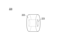
- FIG. 4 is a schematic diagram showing the outer surface and inner surface of an elastic body that constitutes the catheter manufacturing apparatus. 4 is a flow chart showing a method of manufacturing a catheter according to an embodiment of the invention
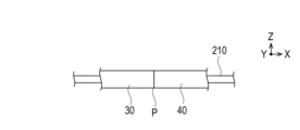
- FIG. 4 is a diagram showing a state in which a first member and a second member are attached to an insertion member that constitutes a catheter manufacturing apparatus;
- FIG. 4 is a diagram showing a state in which the adjacent portions of the first member and the second member are arranged in the hollow portion of the elastic body that constitutes the catheter manufacturing apparatus.
- FIG. 4 is a diagram showing a state in which a hard part constituting the catheter manufacturing apparatus is brought close to an elastic body and an external force is applied to the elastic body. It is a figure which shows a mode that the adjacent part of a 1st member and a 2nd member is irradiated with a laser beam. It is the schematic which shows the irradiation part of the laser beam in a 1st member and a 2nd member.
- FIG. 5 is a schematic diagram showing a modified example of the first embodiment in which the axial length of the hard part is shorter than the axial length of the elastic body.
- FIG. 10 is a schematic diagram showing a catheter manufacturing apparatus used in a catheter manufacturing method according to a second embodiment, and showing a state before components constituting hard parts apply external force to an elastic body.
- FIG. 12 is a diagram showing a state in which an external force is applied to an elastic body by a component in the catheter manufacturing apparatus shown in FIG. 11; 9 is a flow chart showing a method for manufacturing a catheter according to a modified example of the second embodiment;
- FIG. 12B is a view showing a state in which the second hard part is brought into contact with the elastic body in the manufacturing method of the catheter according to the modified example of the second embodiment.
- FIG. 12B is a view showing a state in which the second hard part is brought into contact with the elastic body in the manufacturing
- FIG. 10 is a diagram showing a state in which the adjacent portions of the first member and the second member are arranged in the hollow portion of the elastic body in the manufacturing method of the catheter according to the modified example of the second embodiment
- FIG. 10B is a view showing a case where the first hard component is brought into contact with the elastic body to apply an external force to the elastic body in the manufacturing method of the catheter according to the modified example of the second embodiment.
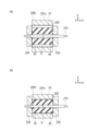
- FIG. 17(a) is a diagram showing the inner volume surrounded by the first hard part and the second hard part at the time of FIG. 15 in the modified example of the second embodiment.
- FIG. 17(b) is a diagram showing the internal volume surrounded by the first hard part and the second hard part at the time of FIG. 16 in the modified example of the second embodiment.
- the catheter 100 manufactured by the method for manufacturing a catheter according to the present embodiment is inserted into a blood vessel, bile duct, trachea, esophagus, urethra, or other biological lumen or body cavity and used for treatment, diagnosis, or the like. be able to.
- the catheter 100 is a balloon catheter, microcatheter, imaging catheter, guiding catheter, or the like used for PTCA (Percutaneous Transluminal Coronary Angioplasty) or PTA (Percutaneous Transluminal Angioplasty).
- FIG. 1 is a schematic diagram showing a catheter 100 manufactured by a catheter manufacturing method according to one embodiment.
- the catheter 100 comprises an elongated catheter body 10 that can be introduced into a living body, and a hub 20 connected to the proximal end of the catheter body 10 .
- the catheter main body 10 is configured to have the anti-kink protector 21 near the joint between the catheter main body 10 and the hub 20, but the anti-kink protector may not necessarily be provided.
- the side of the catheter body 10 on which the hub 20 is arranged is referred to as the proximal side
- the side opposite to the proximal side and the side introduced into the living body is referred to as the distal side.
- the direction of rotation is referred to as the axial direction.
- the catheter body 10 is configured as a flexible tubular member having a lumen extending in the axial direction. As will be described later in this embodiment, the catheter body 10 has two cylindrical members, the first member 30 and the second member 40, arranged in the axial direction, and the adjoining portion P of the first member 30 and the second member 40 is arranged. It is formed by fusing (see FIG. 9, etc.). The adjacent portion P is provided at one axial end of the first member 30 .
- the first member 30 and the second member 40 have a cylindrical shape, and in this embodiment, the cylindrical shape is configured as a cylinder as an example.
- the second member 40 is configured to be arranged closer to the proximal side than the first member 30 in the axial direction.
- the constituent materials of the first member 30 and the second member 40 are, for example, polyamide resins, polyester resins, polyolefin resins, polyurethane resins, polyamide elastomers, polyester elastomers, polyurethane elastomers, mixtures of two or more of these, or materials with different hardness. Mixtures may be mentioned.
- the constituent materials of the first member 30 and the second member 40 preferably contain the same kind of constituent materials.
- the constituent material of the first member 30 is polyamide elastomer
- the constituent material of the second member 40 is polyamide resin.
- the constituent material of the first member 30 is polyester elastomer
- the constituent material of the second member 40 is polyester resin.
- elastomers may be those in which elastomers with different hardness are arranged so that they become flexible from the proximal end to the distal end.
- the constituent material of the first member 30 and the second member 40 may contain polytetrafluoroethylene resin in order to improve the slidability of the inner surfaces.
- first member 30 and the second member 40 can contain pigments or dyes that develop white, black, blue, red, yellow, and mixtures thereof.
- pigments or dyes can be selected from materials that generate heat by absorbing laser light. Examples of materials that generate heat by absorbing laser light include carbon black.
- first member 30 and the second member 40 can be configured to contain powdered contrast medium.
- specific materials include compounds of gold, titanium, bismuth, and tungsten.
- the first member 30 and the second member 40 may have reinforcing bodies made of tungsten, SUS, or the like placed in the above materials.
- the reinforcing body may be coil-shaped or blade-shaped.
- the hub 20 is liquid-tightly fixed to the catheter body 10 with an adhesive, a fixture (not shown), or the like.
- the hub 20 functions as a guide wire insertion port into the lumen of the catheter body 10, an injection port into the lumen for drug solutions, embolic substances, contrast media, etc., and also as a grip when operating the catheter 100. Function.
- the hub 20 may be made of thermoplastic resin such as polycarbonate, polyamide, polysulfone, polyarylate, or the like.
- the catheter 100 has the anti-kink protector 21 as shown in FIG.
- a constituent material of the anti-kink protector 21 for example, natural rubber, silicone resin, or the like can be used.
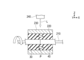
- FIG. 2 is a schematic diagram showing a catheter manufacturing apparatus 200 used in the method for manufacturing the catheter 100 according to the first embodiment.
- an apparatus 200 for manufacturing the catheter 100 includes an insertion member 210, an elastic body 220, a hard component 230 (corresponding to a first hard component), and a laser irradiation section 240.
- X of the orthogonal coordinate system is the axial direction of the first member 30 and the second member 40 that constitute the catheter 100 and is called the axial direction X.
- Y and Z are planes that intersect the axial direction X, and are referred to as planar directions YZ. Details will be described below.
- the insertion member 210 is also called a metal core, and is configured so that the cylindrical first member 30 and the second member 40 to be fused can be inserted.
- the insertion member 210 has a circular cross-sectional shape that intersects the axial direction X in this embodiment.
- the cross-sectional shape of the insertion member 210 is not limited to a circular shape, and may be polygonal or the like.
- the insertion member 210 may be tubular.
- the insertion member 210 can be made of a metal material or the like.
- the insertion member 210 is rotated by a motor, a gear, a bearing, or the like at both ends or both ends of the insertion member 210 so that the fused portions can be formed in the circumferential direction intersecting the axial direction X of the first member 30 and the second member 40 . is rotatably supported with the axial direction X as a rotation axis in the vicinity of the part.
- the elastic body 220 is configured to be elastically deformable so that the first member 30 and the second member 40 to be fused can be brought close to each other.
- the elastic body 220 is configured to be elastically deformable so as to apply radially inward force to the objects to be fused, such as the first member 30 and the second member 40 . While the elastic body 220 maintains a predetermined shape when no load is applied, it can deform toward an unrestrained portion when an external force is applied.
- the elastic body 220 has a hollow portion 221 (see FIG. 6). The hollow portion 221 is configured so that the first member 30 and the second member 40 attached to the insertion member 210 can be inserted with a gap when there is no load.
- the elastic body 220 is configured to have an interference with a hard component 230, which will be described later.
- jigs (not shown) for extending the elastic body 220 in the axial direction X are provided at both ends of the elastic body 220 in the axial direction X in order to facilitate the assembly of the elastic body 220 to the hard part 230.
- the outer diameter D of the elastic body 220 can be smaller than the inner diameter D' of the hard part 230, like the outer diameter D after shown in FIG.
- the elastic body 220 is configured to be elastically deformable so as to come into contact with the first member 30 and the second member 40 to bring the first member 30 and the second member 40 closer to each other under the condition that an external force is applied by a hard component 230 described later. are doing.
- the state in which the first member 30 and the second member 40 are brought close to each other by the hard parts is referred to as the close state.
- a state in which the hard part applies an external force to the elastic body so that the elastic body is displaced toward the fusion target is referred to as an external force applied state.
- hard parts are arranged outside the elastic body in a plurality of directions, the elastic body is pressed by one hard part, and deformation of the elastic body is suppressed or restricted so that the elastic body is not fused. It includes the case where other hard parts are arranged so as not to be displaced in the direction.
- the elastic body 220 is positioned outside the first member 30 and the second member 40 and is irradiated with a laser beam so that the adjoining portions P of the first member 30 and the second member 40 can be fused together.
- a laser beam containing transparent materials.
- laser light transmissive means that the elastic body is made of a material having a transmittance of 80% or more for laser light per 1 mm of radial thickness of the elastic body.
- the elastic body 220 includes a material having higher heat resistance than the first member 30 and the second member 40, which are works, when the first member 30 and the second member 40 are fused.
- materials for the elastic body 220 include silicone rubber and fluororubber.
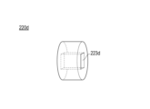
- FIG. 3 is a diagram showing an outer surface 222 and an inner surface 223 of the elastic body 220.
- the elastic body 220 has an outer surface 222 that contacts the hard component 230 in an external force applied state and an inner surface 223 that contacts the first member 30 and the second member 40 in a proximate state.
- the outer surface 222 and the inner surface 223 are both configured to include a cylindrical side profile as shown in FIG. 3 in this embodiment.
- the diameter of the hollow portion 221 in a state where no external force is applied is configured to be larger than the diameters of the first member 30 and the second member 40.
- the elastic body 220 is rotatably supported with the axial direction X as a rotation axis, like the insertion member 210 .
- Hard part 230 is made of a material harder than elastic body 220 .
- the hard part 230 is made of a material that does not substantially deform even when an external force is applied to the elastic body 220 so as to apply a radially inward force to the object to be fused.
- the hard part 230 is configured to be able to apply an external force to the elastic body 220 from the outside so that the elastic body 220 brings the first member 30 and the second member 40 closer together.
- the hard part 230 is configured to apply an external force to the elastic body 220 so that the elastic body 220 applies radially inward force to the objects to be fused such as the first member 30 and the second member 40 .
- the hard part 230 suppresses the weakening of the force due to the elastic deformation of the elastic body 220 that brings the first member 30 and the second member 40 closer together in the state where the external force is applied.
- the hard part 230 is arranged outside the elastic body 220 in the radial direction intersecting the axial direction X in the external force applied state, and applies the external force to the elastic body 220 in the radial direction.
- the hard part 230 is configured to include a hollow tubular member in this embodiment.
- the hard component 230 has an insertion portion N as a cavity through which the elastic body 220 can be inserted, as shown in FIG.
- the elastic body 220 is configured such that the outer surface thereof in the insertion direction under no load has an interference with the insertion portion N of the hard component 230 as described above.
- the outer diameter D (see the two-dot chain line in FIG. 2) of the outer surface of the elastic body 220 is configured to be larger than the inner diameter D' of the hard part 230 as shown in FIG.
- the elastic body 220 is stretched in the axial direction X as described above so that the outer diameter D is smaller than the inner diameter D ' of the hard part 230, and is inserted into the inserting portion N of the hard part 230. can be placed. Further, in this embodiment, the length in the axial direction X of the hard part 230 is configured to be the same as the length in the axial direction X of the elastic body 220 as shown in FIG. 2 and the like.
- the hard part 230 has been described as including a cylindrical member, if an external force can be applied to the elastic body 220 so that the first member 30 and the second member 40 approach each other at the fused portion, the hard part can have a specific shape. is not limited to hollow tubular members.
- the hard part 230 is irradiated with a laser beam toward the adjacent portion P of the first member 30 and the second member 40 while being arranged outside the first member 30 and the second member 40 and the elastic body 220 . Therefore, hard part 230 is configured to have laser light transmittance like elastic body 220 .
- the laser light transmittance of the hard part 230 means that, like the elastic body 220, the hard part is configured so that the transmittance is 80% per 1 mm of the radial thickness of the elastic body.
- the hard part 230 can deform the elastic body 220 into a desired shape, and is harder (higher in hardness) than the elastic body 220 to the extent that the hard part 230 hardly deforms against the reaction force from the elastic body 220.
- a specific material is not particularly limited as long as it can be permeated. Examples of specific materials for the hard part 230 include glass, quartz, sapphire, and the materials mentioned for the elastic body 220 that are harder than the elastic body 220 as described above.
- Hard part 230 can be rephrased as an external force applying member. Further, the hard component 230 is configured to be rotatably supported with the axial direction X as the rotation axis, similarly to the insertion member 210 and the elastic body 220 .
- the laser irradiation unit 240 is used when the adjacent portions P and the like of the first member 30 and the second member 40 are fused.
- the laser irradiation unit 240 includes a light source (not shown) that oscillates a laser, a galvanometer scan (scanner) that changes the laser oscillated from the light source in a predetermined direction by a motor, a mirror, or the like, a prism, and the like.
- the laser irradiation unit 240 irradiates a laser beam having a wavelength that heats the fused portion by radiation heating.
- the spot diameter of the laser beam can be set to ⁇ 0.1 to ⁇ 10 mm, and the wavelength of the laser beam can be set to 800 to 10000 nm.
- the laser beam from the laser irradiation unit 240 can be transmitted through the hard part 230 and the elastic body 220 and irradiated toward the adjacent portion P of the first member 30 and the second member 40 to form the fused portion.
- the adjoining portions to be irradiated with the laser beam are the end surface portions of the two members and their peripheral portions when the two members are aligned in the axial direction. Further, the adjacent portion to be irradiated with the laser beam is the overlapped portion and its peripheral portion when the two members are stacked.
- FIG. 4 is a flow chart showing the method for manufacturing the catheter 100 according to this embodiment
- FIGS. 5 to 9 are diagrams for explaining the method for manufacturing the catheter 100 according to this embodiment.
- a method for manufacturing the catheter 100 according to the present embodiment will be outlined with reference to FIG.
- the elastic body 220 is placed in the hollow portion 221 (S2).
- the method includes application of external force to elastic body 220 by hard part 230 (S3), irradiation of laser light (S4), separation of hard part 230 from elastic body 220 (S5), and The second member 40 is taken out (S6). Details will be described below.
- the first member 30 and the second member 40 are inserted through the insertion member 210 as shown in FIG. 5 (S1).
- the first member 30 and the second member 40 are movable and rotatable integrally with the insertion member 210 .
- the first member 30 and the second member 40 show a state in which their facing end surfaces are in contact with each other.
- a state in which the first member 30 partially overlaps the second member 40 FIG. 19
- a state in which the first member 30 and the second member 40 have a gap can also be included.
- one of the insertion member 210 and the elastic body 220 is moved in the axial direction X in a state where the rotation axes of the insertion member 210 and the elastic body 220 are aligned, and the adjacent portion P between the first member 30 and the second member 40 is moved. is placed in (inside) the hollow portion 221 of the elastic body 220 (S2). In this state, the first member 30 and the second member 40 are not in contact with the hollow portion 221 of the elastic body 220 in the radial direction as shown in FIG. 6, and there is a gap.
- the hard part 230 is brought close to the elastic body 220 and an external force is applied to the elastic body 220 .
- both ends (or the vicinity of both ends) of the elastic body 220 in the axial direction X are held and stretched in the axial direction X so that the outer diameter D of the elastic body 220 is adjusted to the outer diameter D after the outer diameter D as shown in FIG .
- the elastic body 220 is arranged inside the insertion portion N of the hard part 230 in the state where By temporarily reducing the outer diameter of the elastic body 220 in this manner, the elastic body 220 can be easily inserted into the hard component 230 .
- the inner surface 223 of the elastic body 220 which is the wall surface of the hollow portion 221 , moves radially inward due to the external force applied from the hard part 230 . Since deformation of the outer peripheral surface of the elastic body 220 is restricted by the inner peripheral surface of the hard part 230 , the elastic body 220 deforms toward the hollow portion 221 without the restriction by the hard part 230 .
- the first member 30 and the second member 40 are pressed inward in the radial direction r by the elastic body 220 .
- the first member 30 and the second member 40 are in a state of being close to each other, and the hard part 230 is in a state of applying an external force.
- the laser irradiation unit 240 determines the irradiation position of the laser beam by galvano scanning or the like at the adjacent portion P between the first member 30 and the second member 40 as shown in FIG. It is irradiated (S4).
- the insertion member 210, the elastic body 220, and the hard part 230 rotate about the axial direction X as the rotation axis, thereby rotating the first member 30 and the second member 40 about the axial direction X as the rotation axis.
- heat generated by the first member 30 and the second member 40 themselves and/or heat transfer from the insertion member 210 to the first member 30 and the second member 40 causes the first member 30 and the second member 40 to be adjacent to each other.
- a fused portion is formed from the outer periphery to the inside of the portion P.
- the adjacent portion P between the first member 30 and the second member 40 as shown at the position Pt1 in FIG. 9, but also the first member 30 different from the adjacent portion P as shown at the position Pt2 in FIG. is irradiated with laser light L.
- the tip portion of the first member 30 is deformed so that the corner portion of the tip portion of the first member 30 is smoothly formed like a curved surface.
- the irradiation of the laser light L to the positions Pt1 and Pt2 may be performed intermittently or continuously.
- the hard part 230 is separated from the elastic body 220 (S5).
- the hard part 230 is moved relative to the elastic body 220 in the axial direction X to release the external force from the hard part 230 to the elastic body 220 .
- the wall surface of the hollow portion 221 of the elastic body 220 changes from the state in which it was in contact with the first member 30 and the second member 40 as shown in FIG. 7 to the state separated again with a gap as shown in FIG.
- the stretching of the elastic body 220 in the axial direction X may be performed not only in step S3, but also when separating the elastic body 220 from the hard part 230 (S5).
- the insertion member 210 to which the first member 30 and the second member 40 are attached is moved with respect to the elastic body 220, and the joined first member 30 and the second member 40 are removed from the insertion member 210 (S6). .
- the kink-resistant protector 21 and the hub 20 are attached to the catheter main body 10, thereby completing the manufacture of the catheter 100 shown in FIG.
- the first member 30 and the second member 40 are separated in the adjacent state and the external force applied state.
- the adjacent portions P are fused by irradiating the adjacent portions P with laser light L.
- the elastic body 220 is in contact with the first member 30 and the second member 40 by elastic deformation in the hollow portion 221 to bring the first member 30 and the second member 40 closer to each other.
- the elastic body 220 has a hollow portion 221 through which the first member 30 and the second member 40 can be inserted with a gap when no load is applied, and is configured to be elastically deformable.
- the hard part 230 that transmits laser light and is harder than the elastic body 220 is used to suppress the weakening of the force due to the elastic deformation that brings the first member 30 and the second member 40 closer to each other. It is configured to apply an external force to the
- the catheter 100 manufacturing apparatus 200 has an insertion member 210 through which the first member 30 and the second member 40 can be inserted, the elastic body 220 described above, and a hard part 230 .
- the elastic body 220 will change from the state in which it is in contact with the first member 30 and the second member 40. It will be in a state separated with a gap. Therefore, if fusion using a heat-shrinkable tube requires an operation to remove the heat-shrinkable tube from the first member and the second member after fusion-bonding, the method according to the present embodiment can be used. Removal work can be made unnecessary.
- the elastic body 220 returns to the state (state before use) with a gap between the first member 30 and the second member 40 due to elastic deformation without cutting the elastic body itself. can be used to fuse first member 30 and second member 40 multiple times. Therefore, it is possible to save manpower and reduce material costs.
- the shape of the melted portion can be widely selected by controlling the laser beam irradiated portion.
- the elastic body 220 and the hard part 230 have a circular cross section intersecting the axial direction X, the hard part 230 causes the elastic body 220 to evenly distribute the outer periphery of the adjacent portion P between the first member 30 and the second member 40 . Pressurization can improve the quality of the fused portion.
- At least one of the first member 30 and the second member 40 is configured so that the adjacent portion P contains a material that absorbs the laser light L. Therefore, the first member 30 and the second member 40 can be effectively fused together by the heat generated by the absorption of the laser light at the adjacent portion P of the first member 30 and the second member 40 .
- first member 30 and the second member 40 have a cylindrical shape, and according to the manufacturing method according to the present embodiment, the second member 40 is arranged closer to the proximal end side than the first member 30 in the axial direction X.
- Catheter 100 can be manufactured.
- the corresponding portion can be formed into a curved shape or the like.
- the hard part 230 is arranged outside the elastic body 220 in the radial direction intersecting the axial direction X of the first member 30 and the second member 40 in the external force applied state, and applies the external force to the elastic body 220 .
- the adjacent portions P of the first member 30 and the second member 40 can be fused together while suppressing the separation of the first member 30 and the second member 40 .
- the hard part 230 has an insertion portion N through which the elastic body 220 can be inserted.
- the outer surface of the elastic body 220 under no load is formed so as to have an interference with the insertion portion N of the hard part.
- the elastic body 220 is arranged inside the insertion portion N of the hard part 230 in a state in which the outer diameter of the elastic body 220 is made smaller than the inner diameter of the hard part 230 by stretching in the axial direction X.
- the elastic body 220 can be easily arranged inside the insertion portion N of the hard part 230 .
- the elastic body 220 maintains a predetermined shape when no load is applied, and deforms toward the hollow portion 221 of the elastic body 220 not restricted by the hard part 230 when the hard part 230 applies an external force.
- a stable pressurization can be applied to the member to be processed such as the member 30 and the second member 40 .
- the hollow portion 221 of the elastic body 220 can be given an arbitrary shape to process the member to be processed into an arbitrary shape.
- FIG. 10 is a diagram showing a catheter manufacturing apparatus 200a according to a modification of the first embodiment.
- the length in the axial direction X of the hard part 230 is the same as the length in the axial direction X of the elastic body 220 .
- the length in the axial direction X of the hard part is not limited to the above as long as the hard part can apply an external force so that the elastic body brings the first member and the second member close to each other in the axial direction X.
- the length in the axial direction X of the hard part 230a may be shorter than the length in the axial direction X of the elastic body 220 as shown in FIG.
- the configuration of the catheter manufacturing apparatus and the catheter manufacturing method other than the hard parts are the same as those of the first embodiment, so common descriptions are omitted.
- the elastic body 220 when the elastic body 220 is stretched, the elastic body 220 is longer in the axial direction X than the hard part 230 when there is no load. Therefore, since the elastic body 220 is arranged in the hard part 230, the elastic body 220 is provided with a gripping margin, and the insertion and removal of the elastic body 220 are facilitated.
- FIG. 11 is a diagram showing a state before the hard part 230b (corresponding to the first hard part) constituting the catheter manufacturing apparatus 200b according to the second embodiment applies an external force to the elastic body 220
- FIG. 12 shows the hard part 230b. is a diagram showing a state in which external force is applied to the elastic body 220.
- the hard part 230 is configured in the same cylindrical shape as the elastic body 220 and that the hard part 230 is attached to the elastic body 220 so as to fit into the elastic body 220 .
- the hard part can also be configured as follows.
- the inserting member 210, the elastic body 220, and the laser irradiation section 240 are the same as those in the first embodiment, so description thereof will be omitted.
- ⁇ is along the circumferential direction or angular direction of the first member 30, the second member 40, etc. in the plane direction YZ intersecting the axial direction X of the first member 30, the second member 40, and is referred to as the circumferential direction ⁇ .
- the hard part 230b is arranged outside the elastic body 220 in the radial direction r that intersects the axial direction X of the first member 30 and the second member 40 in the external force applied state, and applies the external force to the elastic body 220.
- the hard part 230b includes a plurality of component parts divided by a predetermined number in the circumferential direction ⁇ intersecting the axial direction X of the first member 30 and the second member 40.
- Rigid component 230b is configured to comprise component 231, component 232, and component 233 in this embodiment.
- the component 231, the component 232, and the component 233 elastically deform the elastic body 220 by applying an external force to the elastic body 220 toward the central axis of the first member 30 and the second member 40 in the external force applied state. It consists of The component 231, the component 232, and the component 233 are configured to be movable toward and away from the elastic body 220 in the radial direction r.
- the component 231, the component 232, and the component 233 have inner surfaces 231a, 232a, and 233a as inner surfaces facing the elastic body 220, respectively.
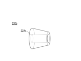
- the component 231, the component 232, and the component 233 each have an outer surface 231b, an outer surface 232b, and an outer surface 233b as outer surfaces with respect to the central axis.
- the elastic body 220 can be in a state with a gap between the first member 30 and the second member 40, or can be in a state in which the elastic body 220 is in contact with the first member 30 and the second member 40. can be done.
- the component parts 231, 232, and 233 come into contact with the elastic body 220 so as to surround the outer periphery of the elastic body 220 when they come into contact with each other.
- the radius of curvature of the inner surfaces 231a, 232a, 233a is smaller than the radius of curvature of the outer surface of the elastic body 220 in the unloaded state.
- the inner surfaces 231a, 232a, 233a form a circle in the planar direction YZ in the state of applying an external force.
- the formed circular cross-sectional area is smaller than the cross-sectional area in the plane direction YZ of the elastic body 220 in the unloaded state.
- the areas of the inner surfaces 231a, 232a, and 233a of the components 231, 232, and 233 are smaller than the areas of the corresponding outer surfaces 231b, 232b, and 233b, respectively.
- the component 231, the component 232, and the component 233 are configured to surround the outer circumference of the elastic body 220 in the circumferential direction ⁇ , which is divided into three equal angles in this embodiment.
- the number of component parts is not limited to three, and the number of component parts is not limited to three, as long as a pressing force can be generated in the adjacent portions P so that the first member 30 and the second member 40 are not separated from each other at the time of fusion bonding. may not be even.
- the hard part 230b can make each of the components 231, 232, and 233 synchronously movable in the radial direction r by hydraulic cylinders (not shown) or the like.
- the components 231, 232, and 233 of the hard part 230b have the axial direction X as the rotation axis at least when the position in the radial direction r is not moved, and are similar to the insertion member 210 and the like of the first embodiment. It is configured to be rotatable.
- steps S1, S2, and S6 are the same as those in the first embodiment, so descriptions thereof will be omitted.
- the elastic body 220 changes its outer diameter from the unloaded state indicated by the two-dot chain line in FIG. 12 to a contracted outer diameter. Since elastic body 220 is restricted in deformation to the outer surface by hard part 230b, it deforms toward unrestricted hollow portion 221. FIG. As a result, the first member 30 and the second member 40 are pressed inward in the radial direction r by the elastic body 220 . Note that the deformation of the hollow portion of the elastic body 220 is omitted in FIG.
- the laser irradiation unit 240 aligns the irradiation position of the laser light L with the adjacent portion P and irradiates the laser light L.
- the insertion member 210, the elastic body 220, and the hard part 230b whose position in the radial direction r is determined rotate about the axial direction X as the rotation axis, so that the first member 30 and the second member 40 are rotated. is irradiated, a fused portion is formed on the outer circumference of the adjacent portion P (S4).
- the laser light L passes through the outer surfaces 231b, 232b, and 233b of the component 231, the component 232, and the component 233 of the hard part 230b, the inner surfaces 231a, 232a, and 233a and the elastic body 220, respectively, to the first member 30 and the second member.
- the outer periphery of the adjacent portion P of the two members 40 is irradiated.
- the components 231, 232, and 233 of the hard part 230b are moved outward in the radial direction r to separate the components 231, 232, and 233 from the elastic body 220. (S5). As a result, the elastic body 220 is separated from the first member 30 and the second member 40 with a gap, as in the first embodiment.
- the hard part 230b is provided with a plurality of component parts 231, 232, and 233 that are divided and arranged in the circumferential direction ⁇ in the state where the external force is applied.
- the plurality of components 231, 232, and 233 are configured to elastically deform the elastic body 220 by applying an external force to the elastic body 220 toward the central axis of the first member 30 and the second member 40. are doing.
- the elastic body 220 is elastically deformed by the hard part 230b in the same manner as in the first embodiment, and the first member 30 and the second member 40 are fused at the adjacent portion P in a state in which a pressing force is applied so that the first member 30 and the second member 40 are not separated from each other. It can be performed.
- the elastic body 220 maintains a predetermined shape when no load is applied, and deforms toward the hollow portion 221 of the elastic body 220 without restriction on deformation by the hard part 230 when an external force is applied by the hard part 230. Therefore, stable pressurization can be applied to the members to be processed such as the first member 30 and the second member 40 . Further, the method of the present embodiment enables fine control of pressurization. Furthermore, the method of the present embodiment can impart an arbitrary shape to the hollow portion 221 of the elastic body 220 to process the workpiece into an arbitrary shape.
- FIG. 13 is a flow chart showing a method for manufacturing a catheter according to a modification of the second embodiment
- FIGS. 14 to 18 are diagrams for explaining a catheter manufacturing apparatus 200c.
- the components 231, 232, and 233 of the hard part 230b apply an external force to the elastic body 220 from the outside to the inside in the radial direction r of the first member 30 and the second member 40. I explained.
- hard parts can be configured as follows. Note that the insertion member 210, the elastic body 220, and the laser irradiation section 240 are the same as those in the first embodiment, so description thereof will be omitted.
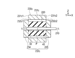
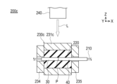
- the hard part 230c includes a first hard part 231c and a second hard part 232c as shown in FIG. 14 and the like.
- the first hard part 231c is arranged outside the elastic body 220 in the radial direction intersecting the axial direction X of the first member 30 and the second member 40 in the external force applied state.
- the first hard component 231c applies an external force to the elastic body 220. As shown in FIG. Since the first hard part 231c includes the component 231, the component 232, and the component 233 described in the second embodiment, the description of the component 231, the component 232, and the component 233 is omitted.
- the second hard component 232c applies an external force to the elastic body 220 from a direction different from that of the first hard component 231c.
- the second hard part 232c is arranged outside the elastic body 220 in the axial direction X different from the radial direction r in which the first hard part 231c applies the external force in this modification.
- the second hard component 232c applies an external force to the elastic body 220. As shown in FIG.
- the second hard part 232c has a component 234 and a component 235, and the component 234 and the component 235 are configured in a substantially cylindrical shape so as to surround the elastic body 220 from the outside in the axial direction X.
- the component 234 and the component 235 of the second hard part 232c are arranged with the surface on the side of the elastic body 220 in contact with the side surface of the elastic body 220 .
- the second hard part 232c can cover the outer surface of the elastic body 220 together with the first hard part 231c.
- the second hard component 232c is rotatably supported with the axial direction X as a rotation axis, like the insertion member 210 and the like of the first embodiment.
- the component 234 and the component 235 are configured to be movable in the axial direction X so that the elastic body 220 can be arranged.
- step S1 in the flowchart of FIG. 13 is the same as step S1 in the flowchart of FIG. 4, so description thereof will be omitted.
- the elastic body 220 is placed at a position where the fused portion is formed in the device (S2).
- the elastic body 220 is arranged at a position where the fused portion is formed while the second hard part 232c is in contact with the elastic body 220 in advance in the axial direction X as shown in FIG.
- the adjacent portion P of the first member 30 and the second member 40 is arranged in the hollow portion 221 of the elastic body 220 in the same manner as in step S2 of FIG. 4 (S3, see FIG. 15).
- the components 231, 232, and 233 of the first hard part 231c are moved in the radial direction r toward the elastic body 220 and brought into contact with each other. That is, the first hard part 231c and the second hard part 232c move one outer surface along the other inner surface. 15, one outer surface 231c1 and the other outer surface 231c2 of the first hard part 231c are moved along one inner surface 232c1 and the other inner surface 232c2 of the second hard part 232c, respectively.
- An external force is applied to the elastic body 220 by the first hard part 231c and the second hard part 232c.
- the elastic body 220 is in a state in which external force is applied in the radial direction r and the axial direction X by the first hard part 231c and the second hard part 232c.
- the inner volume defined by the first hard part 231c and the second hard part 232c is reduced. Specifically, as indicated by the dashed line in FIG. 17A, the internal volume defined by the first hard part 231c and the second hard part 232c under no load is defined as an internal volume V1. On the other hand, as indicated by the dashed line in FIG. 17(b), the inner volume defined by the first hard part 231c and the second hard part 232c in the state where the external force is applied is defined as an inner volume V2. The internal volume defined by the first hard part 231c and the second hard part 232c decreases from the internal volume V1 to the internal volume V2.
- the elastic body 220 shifts from the no-load state to the external force application state. Since the surface of the elastic body 220 is surrounded, the volume of the elastic body 220 is reduced (see D in FIG. 14 and D' in FIG. 16, D>D'). Thus, the volume of the elastic body 220 is reduced due to the reduction in the inner volume defined by the first hard part 231c and the second hard part 232c. As a result, the elastic body 220 shifts from the unloaded state to the external force applied state (S4). In addition, the first member 30 and the second member 40 are brought close to each other by applying an external force to the elastic body 220 by the hard part 230c.
- the laser light L is transmitted through the hard part 230c and the elastic body 220, and the adjacent portion P of the first member 30 and the second member 40 is irradiated.
- the insertion member 210, the elastic body 220, and the hard part 230c rotate to rotate the first member 30 and the second member 40 about the axial direction X as the rotation axis, thereby forming a fused portion on the outer periphery of the adjacent portion P. (S5).
- the first hard part 231 c and the second hard part 232 c are separated from the elastic body 220 . That is, the component 231, the component 232, and the component 233 that constitute the first hard component 231c are moved outward in the radial direction r, and the component 234 and the component 235 that constitute the second hard component 232c are moved in the axial direction. Move outside of X.
- the order in which the first hard part 231c and the second hard part 232c are separated is not particularly limited. As a result, the hard part 230c is separated from the elastic body 220 (S6).
- the fused first member 30 and the second member 40 are taken out from the hollow portion 221 of the elastic body 220 in the same manner as in step S6 of FIG. 4 (S7).
- the hub 20 and anti-kink protector 21 are then attached to form the catheter.
- the hard part 230c includes the first hard part 231c and the second hard part 232c.
- the first hard part 231c is arranged outside the elastic body 220 in the radial direction r, and applies an external force to the elastic body 220 in the radial direction r.
- the second hard component 232c is arranged outside the elastic body 220 in the axial direction X of the first member 30 and the second member 40, and applies an external force to the elastic body 220 in the axial direction X.
- the amount of compression of the elastic body 220 can be reduced and the compression of the elastic body can be easily controlled.
- the elastic body 220 shifts from the no-load state to the external force application state due to the decrease in the inner volume defined by the first hard part 231c and the second hard part 232c. As a result, it is possible to prevent or suppress unintended deformation of the elastic body 220, which may occur if an external force is applied from one direction, and prevent or suppress a decrease in the dimensional accuracy of the finished catheter.
- FIG. 19 is a diagram showing a modification of the first member and the second member. The method of fusing the first member 30 and the second member 40 adjacent in the axial direction X has been described above.
- the direction in which the first member and the second member are arranged is not limited to the axial direction X.
- the two may be fused by a manufacturing device including an insertion member, an elastic body, a hard part, and a laser irradiation section.
- the laser irradiation unit like the laser irradiation unit 240, is the axis of the first member 30 and the second member 40a.
- a laser beam is irradiated from the outside in a radial direction that intersects the two directions toward the adjacent portion, which is the fused portion.
- the elastic body 220 maintains a predetermined shape when no load is applied, and deforms toward the hollow portion 221 of the elastic body 220, which is not restricted by the first hard part 231c and the second hard part 232c, when an external force is applied. Therefore, stable pressurization can be applied to the members to be processed such as the first member 30 and the second member 40 .
- the method of the present embodiment enables fine control of pressurization, and has quick pressurization responsiveness.
- the method of the present embodiment can impart an arbitrary shape to the hollow portion 221 of the elastic body 220 to process the workpiece into an arbitrary shape.
- FIGS. 22 and 23 are diagrams showing modifications of the inner surface of the elastic body.
- the outer surface 222 and the inner surface 223 of the elastic body 220 are described as cylindrical side surfaces in FIG. 3, but the present invention is not limited to this.
- the outer surface 222a of the elastic body 220a may be configured with a side surface of a hexagonal prism, which is an example of a polygonal prism, or as shown in FIG. may be configured.
- the inner surface 223c of the elastic body 220c is configured by the side surface of a truncated cone, or as shown in FIG. You can When the cross sections of the hard part and the elastic body intersecting (perpendicular to) the axial direction X are all formed of only circles, each position in the circumferential direction of the first member and the second member can be uniformly pressurized.
- a position Pt2 corresponding to the tip portion of the first member 30 is irradiated with the laser beam. It has been explained that the light L is applied. However, a case where the position Pt1 is irradiated with the laser light L and the position Pt2 is not irradiated with the laser light L is also included in one embodiment of the present invention.
- the insertion member, the elastic body, and the hard part are rotated to rotate the first member and the second member about the axial direction X as the rotation axis, thereby forming the fused portion on the outer periphery of the adjacent portion P.
- the adjacent portion P of the first member and the second member can be changed.
- a fused portion may be formed on the outer periphery.
- the second hard part 232c is in advance contact with the elastic body 220 when the elastic body 220 is arranged at the position where the fused portion is to be formed in step S2 of FIG.
- the configuration is not limited to this, and the second hard part 232c may be configured to be brought close to the elastic body 220 after the elastic body 220 is arranged at the fused portion forming position.
Landscapes
- Engineering & Computer Science (AREA)
- Mechanical Engineering (AREA)
- Health & Medical Sciences (AREA)
- Physics & Mathematics (AREA)
- Life Sciences & Earth Sciences (AREA)
- Electromagnetism (AREA)
- Biophysics (AREA)
- Pulmonology (AREA)
- Anesthesiology (AREA)
- Biomedical Technology (AREA)
- Heart & Thoracic Surgery (AREA)
- Hematology (AREA)
- Animal Behavior & Ethology (AREA)
- General Health & Medical Sciences (AREA)
- Public Health (AREA)
- Veterinary Medicine (AREA)
- Toxicology (AREA)
- Optics & Photonics (AREA)
- Media Introduction/Drainage Providing Device (AREA)
Abstract
【課題】チューブ同士のような第1部材と第2部材を融着してカテーテルを形成する場合において第1部材と第2部材の融着後に製造に必要な部材の製品からの除去作業を不要にしつつ複数回融着ができることを目的とする。 【解決手段】本発明に係るカテーテルの製造方法は、第1部材30と第2部材40を融着して形成したカテーテル本体10を含むカテーテル100の製造方法であって、以下に述べる近接状態、かつ、外力付与状態において第1部材と第2部材の隣接部分Pにレーザー光を照射して隣接部分を融着させる。近接状態では、レーザー光透過性を有し、無負荷時に第1部材および第2部材が隙間をもって挿通可能な中空部221を有する弾性変形可能な弾性体220が中空部において弾性変形によって第1部材および第2部材と接触して第1部材と第2部材とを近接させる。外力付与状態では、レーザー光透過性を有し弾性体よりも硬い硬質部品230によって第1部材と第2部材とを近接させる弾性変形による力が弱まることを抑制するように弾性体に対して外力を付与する。
Description
本発明は、カテーテルの製造方法およびカテーテルの製造装置に関する。
生体器官内で行われる各種の治療行為を実施するに際して、可撓性を備える管状の中空部材により構成されたチューブ本体を備える医療器具が使用されることが多い。この種の医療器具には、バルーンカテーテル等のカテーテルデバイスを生体内の所望の位置まで送達する際に使用されるガイディングカテーテル、造影剤を生体内に吐出する際に使用される造影カテーテル、薬剤の吐出等に使用されるマイクロカテーテル等が一般に知られている。
上述したカテーテルは、中空のチューブ同士をレーザー等により接合する工程を経て製造する場合がある。このような接合予定部位においてチューブ同士を接合する従来の技術には熱収縮チューブを用いる場合がある(特許文献1参照)。
上述した熱収縮チューブは、接合されるチューブ同士の外方に配置された状態で熱を付与し、熱収縮チューブを収縮させることによって製品となるチューブ同士が接触した状態を保持する。ここで、熱収縮チューブの場合、製品となるチューブは、レーザー等により接合部位を形成した後に熱収縮チューブを製品から取り外す(除去)作業が必要となる。本発明者らは、熱収縮チューブが費用に与える影響が比較的大きく、しかも単回使用で廃却しなくてはならない点に着目した。また、熱収縮チューブの製品からの除去は、作業者によって行われるところ、除去作業の際に熱収縮チューブを製品から上手く除去することができず、作業のやり直しによりコストが増大する点に着目した。
そこで本発明は、上述した課題を解決するためになされたものであり、チューブ同士のような第1部材と第2部材を融着してカテーテルを形成する場合において、第1部材と第2部材の融着後に製造に必要な部材の製品からの除去作業を不要にしつつ複数回融着ができることを目的とする。
上記目的は、本発明の一態様である下記(1)~(11)により達成される。
(1)第1部材と第2部材を融着して形成したカテーテル本体を含むカテーテルの製造方法であって、
レーザー光透過性を有し、無負荷時に前記第1部材および前記第2部材が隙間をもって挿通可能な中空部を有する弾性変形可能な弾性体が前記中空部において弾性変形によって前記第1部材および前記第2部材と接触して前記第1部材と前記第2部材とを近接させた近接状態、かつ、前記レーザー光透過性を有し前記弾性体よりも硬い硬質部品によって前記第1部材と前記第2部材とを近接させる前記弾性変形による力が弱まることを抑制するように前記弾性体に対して外力を付与した外力付与状態において、前記第1部材と前記第2部材の隣接部分にレーザー光を照射して前記隣接部分を融着させるカテーテルの製造方法。
(2)前記第1部材および前記第2部材の少なくとも一方は、前記隣接部分にレーザー光を吸収する材料を含む(1)に記載のカテーテルの製造方法。
(3)前記第1部材および前記第2部材は筒形状を備え、
前記第2部材は前記第1部材よりも軸方向における基端側に配置される(1)または(2)に記載のカテーテルの製造方法。
(4)前記第1部材は、前記軸方向における一方の端部において前記第2部材と近接し、
前記第1部材の前記軸方向において前記隣接部分と異なる端部に前記レーザー光を照射する(3)に記載のカテーテルの製造方法。
(5)前記第1部材および前記第2部材は筒形状を備え、
前記硬質部品は、前記外力付与状態において前記第1部材および前記第2部材の軸方向と交差する径方向において前記弾性体の外方に配置され、前記弾性体に前記外力を付与する第1硬質部品を備える(1)に記載のカテーテルの製造方法。
(6)前記硬質部品は、前記弾性体を挿通可能な挿通部を備え、
無負荷時における前記弾性体の挿通方向における外側面は、前記硬質部品における前記挿通部としめしろを有するように形成される(1)に記載のカテーテルの製造方法。
(7)前記第1部材および前記第2部材は筒形状を備え、
前記弾性体は、前記第1部材および前記第2部材の軸方向に延伸することによって前記弾性体の外径を前記硬質部品の内径より小さくした状態で前記硬質部品の挿通部の内部に配置する(6)に記載のカテーテルの製造方法。
(8)前記硬質部品は、前記外力付与状態において周方向に分割して配置された複数の構成部品を備え、
複数の前記構成部品は、前記外力付与状態において前記第1部材および前記第2部材の中心軸に向かって前記弾性体に前記外力を付与することで前記弾性体を弾性変形させる(1)に記載のカテーテルの製造方法。
(9)前記硬質部品は、前記第1部材および前記第2部材の軸方向において前記弾性体の外方に配置され、前記弾性体に前記外力を付与する第2硬質部品を備える(5)に記載のカテーテルの製造方法。
(10)前記第1硬質部品と前記第2硬質部品によって区画される内容積が減少することにより前記無負荷時から前記外力付与状態に移行する(9)に記載のカテーテルの製造方法。
(11)前記第1部材および前記第2部材を挿通可能な挿通部材と、
(1)から(10)のいずれか1つに記載の前記弾性体と、前記硬質部品と、を有するカテーテルの製造装置。
(1)第1部材と第2部材を融着して形成したカテーテル本体を含むカテーテルの製造方法であって、
レーザー光透過性を有し、無負荷時に前記第1部材および前記第2部材が隙間をもって挿通可能な中空部を有する弾性変形可能な弾性体が前記中空部において弾性変形によって前記第1部材および前記第2部材と接触して前記第1部材と前記第2部材とを近接させた近接状態、かつ、前記レーザー光透過性を有し前記弾性体よりも硬い硬質部品によって前記第1部材と前記第2部材とを近接させる前記弾性変形による力が弱まることを抑制するように前記弾性体に対して外力を付与した外力付与状態において、前記第1部材と前記第2部材の隣接部分にレーザー光を照射して前記隣接部分を融着させるカテーテルの製造方法。
(2)前記第1部材および前記第2部材の少なくとも一方は、前記隣接部分にレーザー光を吸収する材料を含む(1)に記載のカテーテルの製造方法。
(3)前記第1部材および前記第2部材は筒形状を備え、
前記第2部材は前記第1部材よりも軸方向における基端側に配置される(1)または(2)に記載のカテーテルの製造方法。
(4)前記第1部材は、前記軸方向における一方の端部において前記第2部材と近接し、
前記第1部材の前記軸方向において前記隣接部分と異なる端部に前記レーザー光を照射する(3)に記載のカテーテルの製造方法。
(5)前記第1部材および前記第2部材は筒形状を備え、
前記硬質部品は、前記外力付与状態において前記第1部材および前記第2部材の軸方向と交差する径方向において前記弾性体の外方に配置され、前記弾性体に前記外力を付与する第1硬質部品を備える(1)に記載のカテーテルの製造方法。
(6)前記硬質部品は、前記弾性体を挿通可能な挿通部を備え、
無負荷時における前記弾性体の挿通方向における外側面は、前記硬質部品における前記挿通部としめしろを有するように形成される(1)に記載のカテーテルの製造方法。
(7)前記第1部材および前記第2部材は筒形状を備え、
前記弾性体は、前記第1部材および前記第2部材の軸方向に延伸することによって前記弾性体の外径を前記硬質部品の内径より小さくした状態で前記硬質部品の挿通部の内部に配置する(6)に記載のカテーテルの製造方法。
(8)前記硬質部品は、前記外力付与状態において周方向に分割して配置された複数の構成部品を備え、
複数の前記構成部品は、前記外力付与状態において前記第1部材および前記第2部材の中心軸に向かって前記弾性体に前記外力を付与することで前記弾性体を弾性変形させる(1)に記載のカテーテルの製造方法。
(9)前記硬質部品は、前記第1部材および前記第2部材の軸方向において前記弾性体の外方に配置され、前記弾性体に前記外力を付与する第2硬質部品を備える(5)に記載のカテーテルの製造方法。
(10)前記第1硬質部品と前記第2硬質部品によって区画される内容積が減少することにより前記無負荷時から前記外力付与状態に移行する(9)に記載のカテーテルの製造方法。
(11)前記第1部材および前記第2部材を挿通可能な挿通部材と、
(1)から(10)のいずれか1つに記載の前記弾性体と、前記硬質部品と、を有するカテーテルの製造装置。
本発明の一態様に係る上記カテーテルの製造方法およびカテーテルの製造装置によれば、第1部材と第2部材を融着してカテーテルを形成する場合において第1部材と第2部材の融着後に製造に必要な部材の製品からの除去作業を不要にしつつ複数回融着ができる。
以下、本発明を実施するための形態について、図面を参照しながら詳細に説明する。ここで示す実施形態は、本発明の技術的思想を具体化するために例示するものであって、本発明を限定するものではない。また、本発明の要旨を逸脱しない範囲で当業者などにより考え得る実施可能な他の形態、実施例および運用技術などは全て本発明の範囲、要旨に含まれると共に、特許請求の範囲に記載された発明とその均等の範囲に含まれる。
さらに、本明細書に添付する図面は、図示と理解のしやすさの便宜上、適宜縮尺、縦横の寸法比、形状などについて、実物から変更し模式的に表現される場合があるが、あくまで一例であって、本発明の解釈を限定するものではない。
また、以下の説明において、「第1」、「第2」のような序数詞を付して説明するが、特に言及しない限り、便宜上用いるものであって何らかの順序を規定するものではない。
本実施形態に係るカテーテルの製造方法で製造されるカテーテル100は、血管、胆管、気管、食道、尿道、またはその他の生体管腔内や体腔内に挿入されて治療や診断等を行うために用いることができる。カテーテル100は、PTCA(Percutaneous Transluminal Coronary Angioplasty)やPTA(Percutaneous Transluminal Angioplasty)に用いるバルーンカテーテル、マイクロカテーテル、造影カテーテル、またはガイディングカテーテル等である。
図1は一実施形態に係るカテーテルの製造方法により製造されるカテーテル100を示す概略図である。カテーテル100について図1を参照して概説すれば、生体内に導入可能な長尺状のカテーテル本体10と、カテーテル本体10の基端部に連結されるハブ20と、を備えている。カテーテル本体10は、本実施形態においてカテーテル本体10とハブ20の連結部付近に耐キンクプロテクタ21を設けるように構成しているが、耐キンクプロテクタは必ずしも設けられていなくてもよい。
本明細書では、カテーテル本体10においてハブ20が配置される側を基端側と称し、基端側と反対側に位置し、生体内に導入される側を先端側と称し、チューブ本体が延伸する方向を軸方向と称する。
カテーテル本体10は、軸方向に延在するルーメンが形成された可撓性を有する管状の部材として構成している。カテーテル本体10は、本実施形態において後述するように第1部材30および第2部材40という2つの筒状部材を軸方向に並べた状態で第1部材30と第2部材40の隣接部分Pを融着することによって形成している(図9等参照)。隣接部分Pは、第1部材30において軸方向の一方の端部に設けられる。
第1部材30と第2部材40は筒形状を備え、筒形状は本実施形態において一例として円筒に構成している。第2部材40は、第1部材30よりも軸方向において基端側に配置するように構成している。
第1部材30と第2部材40の構成材料は例えばポリアミド樹脂、ポリエステル樹脂、ポリオレフィン樹脂、ポリウレタン樹脂のほか、ポリアミドエラストマー、ポリエステルエラストマー、ポリウレタンエラストマー、あるいはこれらの2種以上の混合物または硬度が異なるものの混合物を挙げることができる。第1部材30と第2部材40の構成材料は同種の構成材料が含まれるのが好ましい。一例として、第1部材30の構成材料はポリアミドエラストマーであり、第2部材40の構成材料はポリアミド樹脂である。別の例としては、第1部材30の構成材料はポリエステルエラストマーであり、第2部材40の構成材料はポリエステル樹脂である。
これらのエラストマーは、基端から先端に向かって柔軟になるように硬度の異なるエラストマーを配列したものでもよい。また、第1部材30および第2部材40の構成材料は内面の摺動性を高めるためにポリテトラフルオロエチレン樹脂を含んでもよい。
また、第1部材30および第2部材40には白色、黒色、青、赤、黄を発色する顔料または染料、およびその混合物を含むことができる。このような顔料または染料は、レーザー光を吸収して発熱するような材料を選択することができる。レーザー光を吸収して発熱する材料としてはカーボンブラック等を挙げることができる。
また、第1部材30および第2部材40は造影剤を粉末状にしたものを含むように構成できる。具体的な材料としては例えば金、チタン、ビスマス、タングステンの化合物等を挙げることができる。さらに、第1部材30および第2部材40は、上述した材料中にタングステンやSUS等からなる補強体を配置してもよい。補強体は、コイル状、ブレード状の形態が挙げられる。
ハブ20は、接着剤や固定具(図示省略)等によりカテーテル本体10と液密に固着している。ハブ20は、カテーテル本体10のルーメン内へのガイドワイヤの挿入口、ルーメン内への薬液や塞栓物質、造影剤等の注入口等として機能し、また、カテーテル100を操作する際の把持部として機能する。ハブ20の材料は、例えばポリカーボネート、ポリアミド、ポリサルホン、ポリアリレート等の熱可塑性樹脂を使用することができる。
なお、図1に示すようにカテーテル100が耐キンクプロテクタ21を有する場合、耐キンクプロテクタ21は、カテーテル本体10の基端部の一部を囲むように設けられる弾性材料により構成することができる。耐キンクプロテクタ21の構成材料としては、例えば天然ゴム、シリコーン樹脂等を使用することができる。
(カテーテルの製造装置)
次に第1実施形態に係るカテーテル100の製造装置200について説明する。図2は第1実施形態に係るカテーテル100の製造方法に用いられるカテーテルの製造装置200を示す概略図である。カテーテル100の製造装置200について図2を参照して概説すれば、挿通部材210と、弾性体220と、硬質部品230(第1硬質部品に相当)と、レーザー照射部240と、を有する。
次に第1実施形態に係るカテーテル100の製造装置200について説明する。図2は第1実施形態に係るカテーテル100の製造方法に用いられるカテーテルの製造装置200を示す概略図である。カテーテル100の製造装置200について図2を参照して概説すれば、挿通部材210と、弾性体220と、硬質部品230(第1硬質部品に相当)と、レーザー照射部240と、を有する。
なお、以下ではカテーテルの製造装置を示す図面に座標系を示す。直交座標系のXはカテーテル100を構成する第1部材30と第2部材40の軸方向であって軸方向Xと称する。Y、Zは軸方向Xと交差する面であって、平面方向YZと称する。以下、詳述する。
(挿通部材)
挿通部材210は芯金とも呼ばれ、融着対象である筒形状の第1部材30と第2部材40とを挿通可能に構成している。挿通部材210は、本実施形態において軸方向Xに交差する断面形状を円形状に構成している。
挿通部材210は芯金とも呼ばれ、融着対象である筒形状の第1部材30と第2部材40とを挿通可能に構成している。挿通部材210は、本実施形態において軸方向Xに交差する断面形状を円形状に構成している。
ただし、第1部材30および第2部材40を挿通して取り付けることができれば挿通部材210の断面形状は円形状に限定されず、多角形などであってもよい。また、挿通部材210は、管状であってもよい。挿通部材210は、金属材料などから構成することができる。また、挿通部材210は、第1部材30および第2部材40の軸方向Xと交差する周方向に融着部位を形成できるように、モーター、ギヤ、軸受け等によって挿通部材210の両端部または両端部付近において軸方向Xを回転軸として回転可能に支持される。
(弾性体)
弾性体220は、融着対象となる第1部材30と第2部材40とを近接させることができるように弾性変形可能に構成している。弾性体220は、第1部材30と第2部材40などの融着対象物に対してその融着対象物の径方向内側への力を与えるように弾性変形可能に構成している。弾性体220は無負荷時には所定形状を維持している一方、外力が付与された場合には拘束のない部分に向かって変形することができる。弾性体220は、中空部221を備える(図6参照)。中空部221は、無負荷時に挿通部材210に取り付けた第1部材30および第2部材40を、隙間をもって挿通可能に構成している。
弾性体220は、融着対象となる第1部材30と第2部材40とを近接させることができるように弾性変形可能に構成している。弾性体220は、第1部材30と第2部材40などの融着対象物に対してその融着対象物の径方向内側への力を与えるように弾性変形可能に構成している。弾性体220は無負荷時には所定形状を維持している一方、外力が付与された場合には拘束のない部分に向かって変形することができる。弾性体220は、中空部221を備える(図6参照)。中空部221は、無負荷時に挿通部材210に取り付けた第1部材30および第2部材40を、隙間をもって挿通可能に構成している。
また、弾性体220は、後述する硬質部品230としめしろを有するように構成している。また、本実施形態では上述した弾性体220を硬質部品230に組み付けやすくするために軸方向Xにおける弾性体220の両端部には弾性体220を軸方向Xに延伸させる治具(図示省略)を取り付け可能に構成している。これにより、弾性体220の外径Dは図2に示す外径Dafterのように硬質部品230の内径D´より小さくすることができる。
弾性体220は、後述する硬質部品230により外力を付与された状態で第1部材30および第2部材40に接触して第1部材30と第2部材40を近接させるように弾性変形可能に構成している。本明細書において硬質部品により第1部材30と第2部材40とが近接した状態を近接状態と称する。また、本明細書において弾性体が融着対象に向けて変位するように硬質部品が弾性体に外力を付与する状態を外力付与状態と称する。外力付与状態には、弾性体の複数方向における外方に硬質部品を配置し、一の硬質部品により弾性体を加圧し、弾性体の変形を抑制又は制限して弾性体が融着対象以外の方向に変位しないように他の硬質部品を配置等する場合を含む。
弾性体220は、第1部材30および第2部材40の外方に位置した状態でレーザー光を照射した際に第1部材30と第2部材40の隣接部分Pを融着できるようにレーザー光透過性を有する材料を含む。レーザー光透過性は、本明細書において弾性体の径方向の厚さが1mmにつきレーザー光に対する透過率80%以上の材料にて構成することを意味する。
また、弾性体220は、第1部材30と第2部材40との融着時にワークである第1部材30と第2部材40より耐熱性を有する材料を含む。弾性体220の材料について例示すれば、シリコーンゴムやフッ素ゴム等を挙げることができる。
図3は弾性体220の外面222および内面223を示す図である。弾性体220は、外力付与状態で硬質部品230と接触する外面222および近接状態で第1部材30および第2部材40と接触する内面223を備える。外面222および内面223は、本実施形態において図3に示すように、ともに円筒の側面形状を含むように構成している。
図3のように中空部221の軸方向Xと直交する断面が円である場合、外力を付与しない状態の中空部221の径は、第1部材30および第2部材40の径より大きく構成している。また、弾性体220は、挿通部材210と同様に軸方向Xを回転軸として回転可能に支持される。
(硬質部品)
硬質部品230は、弾性体220より硬い材料によって構成される。硬質部品230は、融着対象物の径方向内側への力を与えるように弾性体220に外力を付与されても実質的に変形しない材料によって構成される。硬質部品230は、弾性体220によって第1部材30と第2部材40とが近接状態となるように弾性体220の外方から弾性体220に外力を付与可能に構成している。硬質部品230は、弾性体220によって第1部材30と第2部材40などの融着対象物の径方向内側への力を与えるように弾性体220に外力を付与可能に構成している。
硬質部品230は、弾性体220より硬い材料によって構成される。硬質部品230は、融着対象物の径方向内側への力を与えるように弾性体220に外力を付与されても実質的に変形しない材料によって構成される。硬質部品230は、弾性体220によって第1部材30と第2部材40とが近接状態となるように弾性体220の外方から弾性体220に外力を付与可能に構成している。硬質部品230は、弾性体220によって第1部材30と第2部材40などの融着対象物の径方向内側への力を与えるように弾性体220に外力を付与可能に構成している。
硬質部品230は、外力付与状態において第1部材30と第2部材40とを近接させる弾性体220の弾性変形による力が弱まることを抑制する。硬質部品230は、本実施形態では外力付与状態において軸方向Xと交差する径方向において弾性体220の外方に配置され、弾性体220に対して径方向に外力を付与する。
硬質部品230は、本実施形態において中空の筒状部材を含むように構成している。硬質部品230は、図2に示すように弾性体220を挿通可能な空洞として挿通部Nを備える。弾性体220は、無負荷時における挿通方向における外側面が上述のように硬質部品230における挿通部Nとしめしろを有するように構成している。換言すれば、弾性体220の外側面の外径D(図2の二点鎖線参照)は、図2に示すように硬質部品230の内径D´よりも大きくなるよう構成している。
弾性体220は、上述のように軸方向Xに延伸させることによって外径Dを外径Dafterのように硬質部品230の内径D´より小さくした状態で硬質部品230の挿通部Nの内部に配置することができる。また、本実施形態において硬質部品230の軸方向Xにおける長さは、図2等に示すように弾性体220の軸方向Xにおける長さと同一に構成している。
硬質部品230は筒状部材を含むと説明したが、第1部材30と第2部材40とが融着部分にて近接するように弾性体220に外力を付与できれば、硬質部品の具体的な形状は中空の筒状部材に限定されない。
硬質部品230は、第1部材30および第2部材40と弾性体220の外方に配置された状態で第1部材30および第2部材40の隣接部分Pに向けてレーザー光が照射される。そのため、硬質部品230は弾性体220と同様にレーザー光透過性を有するように構成している。硬質部品230におけるレーザー光透過性は弾性体220と同様に弾性体の径方向の厚さが1mmにつき透過率80%となるように硬質部品を構成することを意味する。
硬質部品230は弾性体220を所望の形状に変形でき、かつ、弾性体220からの反力に対して硬質部品230がほぼ変形しない程度に弾性体220より硬く(硬度が高く)、レーザー光が透過できれば具体的な材料は特に限定されない。硬質部品230の具体的な材料を例示すれば、ガラス、石英、サファイア、または弾性体220にて言及した材料において弾性体220よりも上記のように硬度の高い材料を挙げることができる。硬質部品230は、外力付与部材と言い換えることができる。また、硬質部品230は、挿通部材210および弾性体220と同様に、軸方向Xを回転軸として回転可能に支持されるように構成している。
(レーザー照射部)
レーザー照射部240は、第1部材30と第2部材40の隣接部分P等を融着する際に用いられる。レーザー照射部240は、レーザーを発振させる不図示の光源と、光源から発振したレーザーをモーターやミラー等によって所定の方向に変化させるガルバノスキャン(スキャナ)、プリズム等を含む。
レーザー照射部240は、第1部材30と第2部材40の隣接部分P等を融着する際に用いられる。レーザー照射部240は、レーザーを発振させる不図示の光源と、光源から発振したレーザーをモーターやミラー等によって所定の方向に変化させるガルバノスキャン(スキャナ)、プリズム等を含む。
レーザー照射部240は、輻射加熱により融着部を発熱させる波長のレーザー光を照射する。レーザー光のスポット径は、φ0.1~φ10mmに構成でき、レーザー光の波長は800~10000nmに構成できる。これにより、レーザー照射部240からのレーザー光を硬質部品230および弾性体220を透過して第1部材30および第2部材40の隣接部分Pに向けて照射して融着部位を形成することができる。レーザー光を照射する隣接部分とは、2つの部材を軸方向に並べた状態において両部材の端面部分及びその周辺部分である。また、レーザー光を照射する隣接部分とは、2つの部材を重ねた状態において重複した部分やその周辺部分である。
(カテーテルの製造方法)
次に本実施形態に係るカテーテル100の製造方法について説明する。図4は本実施形態に係るカテーテル100の製造方法を示すフローチャート、図5~図9は本実施形態に係るカテーテル100の製造方法の説明に供する図である。
次に本実施形態に係るカテーテル100の製造方法について説明する。図4は本実施形態に係るカテーテル100の製造方法を示すフローチャート、図5~図9は本実施形態に係るカテーテル100の製造方法の説明に供する図である。
本実施形態に係るカテーテル100の製造方法について図4を参照して概説すれば、第1部材30と第2部材40の挿通部材210への取り付け(S1)、第1部材30と第2部材40の弾性体220の中空部221への配置(S2)を行う。また、当該方法は、硬質部品230による弾性体220への外力の付与(S3)、レーザー光の照射(S4)、硬質部品230の弾性体220からの離間(S5)および第1部材30と第2部材40の取り出し(S6)を行う。以下、詳述する。
まず、第1部材30と第2部材40は、図5に示すように挿通部材210に挿通される(S1)。この状態で第1部材30と第2部材40は挿通部材210と一体的に移動可能および回転可能になる。なお、図5において第1部材30と第2部材40は向かい合った端面が接触した状態を表している。しかしながら、後述するように第1部材30が第2部材40の一部に重複した状態(図19)や第1部材30と第2部材40に隙間を有する状態も含みうる。
次に、挿通部材210と弾性体220の回転軸を合わせた状態において挿通部材210および弾性体220のいずれか一方を軸方向Xに移動させて第1部材30と第2部材40の隣接部分Pを弾性体220の中空部221(の内部)に配置する(S2)。この状態で第1部材30と第2部材40は図6に示すように径方向において弾性体220の中空部221と接しておらず、隙間が生じている。
次に、図7に示すように硬質部品230を弾性体220に接近させて弾性体220に外力を付与する。本実施形態では、弾性体220の軸方向Xにおける両端部(または両端部近傍)を把持して軸方向Xに延伸させ、図2に示すように弾性体220の外径Dを外径Dafterにした状態で弾性体220を硬質部品230の挿通部Nの内部に配置する。このように弾性体220の外径を一時的に小さくすることによって弾性体220を硬質部品230に挿通しやすくできる。
弾性体220を硬質部品230の挿通部Nの内部に配置した後、弾性体220の軸方向Xの外方への伸張を解除する。これにより、弾性体220の外径Dafterは径方向外方に変位し、硬質部品230の内面が弾性体220の外面と接触して硬質部品230により弾性体220は径方向内方に外力が付与される(S3)。弾性体220の外面222は、硬質部品230の内面と密着しつつ、弾性体220は硬質部品230により径方向内方に縮む力が付与される。そして、中空部221の壁面である弾性体220の内面223は硬質部品230から付与された外力によって径方向内方に移動する。弾性体220の外周面は硬質部品230の内周面によって変形が制限されているので、硬質部品230による制限のない弾性体220の中空部221に向かって変形する。
その結果、第1部材30と第2部材40は弾性体220により径方向rの内方に押圧される。中空部221の壁面である内面223が第1部材30および第2部材40と接触して第1部材30および第2部材40が軸方向Xに押圧しあう。ここで、第1部材30と第2部材40とが近接状態となり、硬質部品230が外力付与状態となる。
次に、レーザー照射部240は、ガルバノスキャン等によってレーザー光の照射位置を図8に示すように第1部材30と第2部材40との隣接部分Pに定め、レーザー光Lが隣接部分Pに照射される(S4)。本実施形態では挿通部材210、弾性体220、および硬質部品230が軸方向Xを回転軸として回転することによって、第1部材30と第2部材40が軸方向Xを回転軸として回転する。これにより、第1部材30と第2部材40自身の発熱、及び/又は、挿通部材210から第1部材30と第2部材40への伝熱によって、第1部材30と第2部材40の隣接部分Pの外周から内部にかけて融着部位が形成される。
また、本実施形態では図9の位置Pt1に示すように第1部材30と第2部材40の隣接部分Pだけでなく、図9の位置Pt2に示すように隣接部分Pと異なる第1部材30の先端部にレーザー光Lが照射される。これにより、第1部材30の先端部が変形して第1部材30の先端部における角部が曲面のように滑らかに形成される。なお、位置Pt1、位置Pt2へのレーザー光Lの照射は断続的に行ってもよく、連続的に行ってもよい。
次に、硬質部品230を弾性体220から離間させる(S5)。本実施形態では弾性体220に対して硬質部品230を軸方向Xに相対的に移動させて硬質部品230による弾性体220への外力の付与を解除する。これにより、弾性体220の中空部221の壁面は図7に示すように第1部材30および第2部材40と接していた状態から図6に示すように再び隙間をもって離間した状態となる。
なお、弾性体220の軸方向Xにおける延伸はステップS3だけでなく、弾性体220を硬質部品230から離間させる際(S5)に行ってもよい。
次に、弾性体220に対して第1部材30と第2部材40を取り付けた挿通部材210を移動させて、挿通部材210から接合された第1部材30および第2部材40を取り外す(S6)。その後、カテーテル本体10に対して耐キンクプロテクタ21およびハブ20を取り付ける作業を行うことにより、図1に示すカテーテル100の製造が完了する。
以上説明したように本実施形態に係る筒形状を備える第1部材30と第2部材40とを含むカテーテル100の製造方法は、近接状態および外力付与状態において第1部材30と第2部材40の隣接部分Pにレーザー光Lを照射して隣接部分Pを融着させる。
近接状態ではレーザー光透過性を有し、弾性体220が中空部221において弾性変形によって第1部材30および第2部材40と接触して第1部材30と第2部材40とを近接させる。弾性体220は、無負荷時に第1部材30および第2部材40が隙間をもって挿通可能な中空部221を有し、弾性変形可能に構成している。
外力付与状態では、レーザー光透過性を有し弾性体220よりも硬い硬質部品230によって第1部材30と第2部材40とを近接させる弾性変形による力が弱まることを抑制するように弾性体220に対して外力を付与するように構成している。
また、カテーテル100の製造装置200は、第1部材30および第2部材40を挿通可能な挿通部材210と、上述した弾性体220と、硬質部品230と、を有する。
このように構成することによって、レーザー光Lの照射後に硬質部品230による弾性体220への外力の付与を停止すれば弾性体220は第1部材30および第2部材40に対して接触した状態から隙間をもって離間した状態となる。そのため、熱収縮チューブを用いた融着であれば融着後に第1部材および第2部材から熱収縮チューブを除去する作業が必要になるところ、本実施形態に係る方法を用いることによってこのような除去作業を不要にすることができる。
これにより、熱収縮チューブの場合のようなチューブ除去の失敗によるやり直しが発生しないか、またはやり直しの発生を低減できる。また、弾性体220は弾性体自身を切断したりすることなく、弾性変形により第1部材30と第2部材40に対して隙間をもった状態(使用前の状態)に戻るため、弾性体220は第1部材30と第2部材40の複数回の融着に使用できる。そのため、省人化や材料費等の削減を図ることができる。
また、レーザー光Lの照射部位付近に第1部材30と第2部材40の溶融部分が形成されるので、レーザー光照射部位の制御にて溶融部分の形態を幅広く選択できる。さらに、弾性体220および硬質部品230の軸方向Xに交差する断面が円形状からなる場合に硬質部品230によって弾性体220が第1部材30と第2部材40の隣接部分Pの外周を均一に加圧すれば、融着部位の品質を向上させることができる。
また、第1部材30および第2部材40の少なくとも一方は隣接部分Pにレーザー光Lを吸収する材料を含むように構成している。そのため、第1部材30と第2部材40の隣接部分Pにおいてレーザー光吸収による発熱にて第1部材30と第2部材40とを効果的に融着することができる。
また、第1部材30および第2部材40は筒形状を備え、本実施形態に係る製造方法によれば、第2部材40が第1部材30よりも軸方向Xにおいて基端側に配置されるカテーテル100を製造することができる。
また、本実施形態に係る製造方法では第1部材30の軸方向Xにおいて隣接部分Pと異なる先端部等にレーザー光Lを照射することによって該当部分を曲面形状等に成形することができる。
また、硬質部品230は外力付与状態において第1部材30および第2部材40の軸方向Xと交差する径方向において弾性体220の外方に配置され、弾性体220に外力を付与する。このように構成することによって、第1部材30と第2部材40とが離間することを抑制して第1部材30と第2部材40の隣接部分Pを融着することができる。
また、硬質部品230は弾性体220を挿通可能な挿通部Nを備える。無負荷時における弾性体220の外側面は、硬質部品における挿通部Nとしめしろを有するように形成している。このように硬質部品230を弾性体220の外径部分に嵌合させるように配置することによって、第1部材30と第2部材40を互いに近接させるような外力を弾性体220に付与することができる。
また、弾性体220は、軸方向Xに延伸することによって弾性体220の外径を硬質部品230の内径より小さくした状態で硬質部品230の挿通部Nの内部に配置する。このように構成することにより、硬質部品230の挿通部Nの内部に弾性体220を容易に配置できる。
本実施形態において、弾性体220は無負荷時には所定形状を維持し、且つ、硬質部品230による外力付与時には硬質部品230による制限のない弾性体220の中空部221に向かって変形するので、第1部材30および第2部材40などの被加工部材に対して安定した加圧が可能となる。また、本実施形態の方法は、弾性体220の中空部221に任意の形状を付与して被加工部材を任意の形状に加工することができる。
(第1実施形態の変形例)
図10は第1実施形態の変形例に係るカテーテルの製造装置200aについて示す図である。第1実施形態では硬質部品230の軸方向Xにおける長さが弾性体220の軸方向Xにおける長さと同一であると説明した。ただし、硬質部品によって弾性体が第1部材と第2部材を軸方向Xに近接させるように外力を付与できれば硬質部品の軸方向Xにおける長さは上記に限定されない。
図10は第1実施形態の変形例に係るカテーテルの製造装置200aについて示す図である。第1実施形態では硬質部品230の軸方向Xにおける長さが弾性体220の軸方向Xにおける長さと同一であると説明した。ただし、硬質部品によって弾性体が第1部材と第2部材を軸方向Xに近接させるように外力を付与できれば硬質部品の軸方向Xにおける長さは上記に限定されない。
上記以外にも硬質部品230aの軸方向Xにおける長さは図10に示すように弾性体220の軸方向Xにおける長さより短くしてもよい。なお、硬質部品以外のカテーテルの製造装置の構成およびカテーテルの製造方法は第1実施形態と同様であるため、共通する説明を省略する。
本実施形態は、弾性体220を延伸した状態で、無負荷時において硬質部品230に対し弾性体220の方が軸方向Xに長く構成している。そのため、硬質部品230の中に弾性体220を配置していく関係上、弾性体220に掴みしろを設けられ、弾性体220の挿入と取り出しがしやすくなる。
(第2実施形態)
図11は第2実施形態に係るカテーテルの製造装置200bを構成する硬質部品230b(第1硬質部品に相当)が弾性体220に外力を付与する前の状態を示す図、図12は硬質部品230bが弾性体220に外力を付与した状態を示す図である。
図11は第2実施形態に係るカテーテルの製造装置200bを構成する硬質部品230b(第1硬質部品に相当)が弾性体220に外力を付与する前の状態を示す図、図12は硬質部品230bが弾性体220に外力を付与した状態を示す図である。
第1実施形態では硬質部品230を弾性体220と同様に筒形状に構成し、弾性体220に対して嵌合するように硬質部品230を弾性体220に取り付けると説明した。ただし、硬質部品は以下のように構成することもできる。なお、本実施形態において挿通部材210、弾性体220およびレーザー照射部240は第1実施形態と同様であるため、説明を省略する。
なお、図11、図12では図面に円筒座標を表記している。円筒座標系のrは、平面方向YZに沿い、カテーテル100を構成する第1部材30および第2部材40の中心から径方向または放射方向に延びる方向であって、径方向rと称する。θは第1部材30および第2部材40の軸方向Xと交差する平面方向YZにおいて第1部材30および第2部材40等の周方向または角度方向に沿い、周方向θと称する。
硬質部品230bは、外力付与状態において第1部材30および第2部材40の軸方向Xと交差する径方向rにおいて弾性体220の外方に配置され、弾性体220に外力を付与する。硬質部品230bは、図11に示すように第1部材30と第2部材40の軸方向Xと交差する周方向θにおいて所定個数分割された複数の構成部品を備える。硬質部品230bは、本実施形態において構成部品231、構成部品232、構成部品233を備えるように構成している。
構成部品231、構成部品232、構成部品233は、外力付与状態において第1部材30および第2部材40の中心軸に向かって弾性体220に外力を付与することで弾性体220を弾性変形させるように構成している。構成部品231、構成部品232、構成部品233は、径方向rにおいて弾性体220に対して接近離間するように移動自在に構成している。構成部品231、構成部品232、構成部品233は、弾性体220に相対する内面として、各々内面231a,内面232a,内面233aを有する。構成部品231、構成部品232、構成部品233は、中心軸に対して外側の面として、各々外面231b,外面232b,外面233bを有する。
このように構成することによって弾性体220を第1部材30および第2部材40と隙間をもった状態としたり、弾性体220を第1部材30および第2部材40と接触した状態としたりすることができる。
構成部品231、構成部品232、構成部品233は、弾性体220と接触した際に弾性体220の外周を包囲するように接触する。内面231a,232a,233aの曲率半径は、無負荷状態の弾性体220の外面の曲率半径よりも小さい。内面231a,232a,233aは、外力付与状態で平面方向YZにおいて円形を形成する。形成された円形の断面積は無負荷状態の弾性体220の平面方向YZにおける断面積よりも小さい。構成部品231、構成部品232、構成部品233の各々の内面231a,内面232a,内面233aの面積は、各々対応する外面231b,外面232b,外面233bの面積よりも小さい。構成部品231、構成部品232、構成部品233は、本実施形態において均等な角度で3分割された周方向θにおける弾性体220の外周を各々が包囲するように構成している。
ただし、第1部材30と第2部材40が融着時に離間しないように隣接部分Pにおいて押圧しあう力を生じさせることができれば、構成部品の個数は3つに限定されず、構成部品の角度も均等でなくてもよい。
硬質部品230bは、構成部品231、構成部品232、構成部品233の各々を油圧シリンダー(図示せず)などにより径方向rに同期させて移動可能にすることができる。また、硬質部品230bの構成部品231、構成部品232、構成部品233は、少なくとも径方向rにおける位置が移動していないときに軸方向Xを回転軸として第1実施形態の挿通部材210等と同様に回転可能に構成している。
次に本実施形態に係るカテーテルの製造方法について説明する。なお、ステップS1、ステップS2、およびステップS6は第1実施形態と同様であるため、説明を省略する。
弾性体220の中空部221に第1部材30と第2部材40の隣接部分Pを配置した後、図12に示すように硬質部品230bの構成部品231、構成部品232、構成部品233を弾性体220に向けて径方向rに移動させ、接触させる。硬質部品230bの構成部品231、構成部品232、構成部品233は、弾性体220を径方向rに押圧する。これにより、弾性体220は硬質部品230bによって径方向rの内方に外力が付与され(S3)、弾性体220の弾性変形により第1部材30と第2部材40が隣接部分Pにおいて互いに押圧しあう状態となる。弾性体220は、図12の二点鎖線に示す無負荷状態の外径から収縮した外径に変更している。弾性体220は硬質部品230bによって外表面への変形が制限されているので、制限のない中空部221に向かって変形する。これにより第1部材30と第2部材40は弾性体220により径方向rの内方に押圧される。なお、図12においては弾性体220の中空部の変形は省略した。
この状態においてレーザー照射部240がレーザー光Lの照射位置を隣接部分Pに合わせ、レーザー光Lを照射する。挿通部材210、弾性体220、および径方向rにおける位置が定められた硬質部品230bが軸方向Xを回転軸として回転することで第1部材30と第2部材40が回転した状態でレーザー光Lが照射されると隣接部分Pの外周に融着部位が形成される(S4)。レーザー光Lは、硬質部品230bの構成部品231、構成部品232、構成部品233の外面231b,外面232b,外面233bから内面231a,232a,233a及び弾性体220を各々通って第1部材30と第2部材40の隣接部分Pの外周に照射される。
融着が終了した後、硬質部品230bの構成部品231、構成部品232、構成部品233を径方向rの外方に移動させて構成部品231、構成部品232、構成部品233を弾性体220から離間させる(S5)。これにより、弾性体220は第1実施形態と同様に第1部材30および第2部材40と接触していた状態から隙間をもって離間した状態となる。
以上説明したように第2実施形態では硬質部品230bが外力付与状態において周方向θに分割して配置された複数の構成部品231、構成部品232、構成部品233を備える。複数の構成部品231、構成部品232、構成部品233は、第1部材30および第2部材40の中心軸に向かって弾性体220に外力を付与することで弾性体220を弾性変形させるように構成している。
このように硬質部品230bによって第1実施形態と同様に弾性体220を弾性変形させて第1部材30と第2部材40とが離間しないように押圧力を付与した状態において隣接部分Pにおいて融着を行うことができる。
また、本実施形態において、弾性体220は無負荷時には所定形状を維持し、且つ、硬質部品230による外力付与時には硬質部品230による変形に対する制限のない弾性体220の中空部221に向かって変形するので、第1部材30および第2部材40などの被加工部材に対して安定した加圧が可能となる。また、本実施形態の方法は、細かな加圧の制御が可能となる。更に、本実施形態の方法は、弾性体220の中空部221に任意の形状を付与して被加工部材を任意の形状に加工することができる。
(第2実施形態の変形例)
図13は第2実施形態の変形例に係るカテーテルの製造方法を示すフローチャート、図14~図18はカテーテルの製造装置200cの説明に供する図である。第2実施形態では硬質部品230bの構成部品231、構成部品232、構成部品233が第1部材30および第2部材40の径方向rの外方から内方に向かって弾性体220に外力を付与すると説明した。
図13は第2実施形態の変形例に係るカテーテルの製造方法を示すフローチャート、図14~図18はカテーテルの製造装置200cの説明に供する図である。第2実施形態では硬質部品230bの構成部品231、構成部品232、構成部品233が第1部材30および第2部材40の径方向rの外方から内方に向かって弾性体220に外力を付与すると説明した。
ただし、硬質部品は以下のように構成することができる。なお、挿通部材210、弾性体220、およびレーザー照射部240は第1実施形態と同様であるため、説明を省略する。
硬質部品230cは、図14等に示すように第1硬質部品231cと第2硬質部品232cと、を備える。第1硬質部品231cは、外力付与状態において第1部材30および第2部材40の軸方向Xと交差する径方向において弾性体220の外方に配置される。第1硬質部品231cは弾性体220に外力を付与する。第1硬質部品231cは第2実施形態で説明した構成部品231、構成部品232、構成部品233を備えるため、構成部品231、構成部品232、構成部品233の説明を省略する。
第2硬質部品232cは、第1硬質部品231cと異なる方向から弾性体220に外力を付与する。第2硬質部品232cは、本変形例において第1硬質部品231cが外力を付与する径方向rと異なる軸方向Xにおいて弾性体220の外方に配置される。第2硬質部品232cは弾性体220に外力を付与する。
第2硬質部品232cは構成部品234、構成部品235を備え、構成部品234、構成部品235は軸方向Xの外方から弾性体220を包囲するように略円筒形に構成している。第2硬質部品232cの構成部品234及び構成部品235は、弾性体220側の面を弾性体220の側面に接触した状態で配置される。このように構成することによって、第2硬質部品232cは第1硬質部品231cとともに弾性体220の外表面を覆うことができる。また、第2硬質部品232cは、第1実施形態の挿通部材210等と同様に軸方向Xを回転軸として回転可能に支持される。さらに、構成部品234と構成部品235は弾性体220を配置できるように軸方向Xに移動可能に構成している。
次に、図13を参照して本変形例に係るカテーテル100の製造方法について説明する。なお、本変形例において図13のフローチャートにおけるステップS1は図4のフローチャートにおけるステップS1と同様であるため、説明を省略する。
挿通部材210に第1部材30と第2部材40を取り付けた後、装置において融着部位を形成する位置に弾性体220を配置する(S2)。ここで、弾性体220は、第2硬質部品232cが軸方向Xにおいて図14に示すように弾性体220に予め接触した状態で融着部位を形成する位置に配置される。次に、図4のステップS2と同様に弾性体220の中空部221に第1部材30と第2部材40の隣接部分Pを配置する(S3、図15参照)。
次に、図16に示すように第1硬質部品231cの構成部品231、構成部品232、構成部品233を弾性体220に向けて径方向rに移動させ、接触させる。すなわち、第1硬質部品231cと第2硬質部品232cは、一方の外側面を他方の内側面に沿って移動させる。図15において説明すると、第1硬質部品231cの一方の外側面231c1及び他方の外側面231c2を第2硬質部品232cの一方の内側面232c1及び 他方の内側面232c2に沿って各々移動させる。そして、第1硬質部品231cと第2硬質部品232cとによって弾性体220に外力を付与する。これにより、弾性体220は第1硬質部品231cと第2硬質部品232cによって径方向rと軸方向Xに外力が付与された状態となる。
図17(a)及び図17(b)に示すように、第1硬質部品231cと第2硬質部品232cによって区画される内容積が減少する。具体的には、図17(a)の一点鎖線に示すように、無負荷時において第1硬質部品231cと第2硬質部品232cによって区画される内容積を内容積V1とする。一方、図17(b)の一点鎖線に示すように、外力付与状態において第1硬質部品231cと第2硬質部品232cによって区画される内容積を内容積V2とする。第1硬質部品231cと第2硬質部品232cによって区画される内容積は、内容積V1から内容積V2へ減少する。このことにより、弾性体220は前記無負荷時から前記外力付与状態に移行する。弾性体220の表面が包囲されることで弾性体220の体積が減少する(図14のDおよび図16のD´参照、D>D´)。このように第1硬質部品231cと第2硬質部品232cによって区画される内容積の減少により弾性体220の体積が減少する。このことによって弾性体220は無負荷状態から外力付与状態に移行する(S4)。また、硬質部品230cによって弾性体220に外力が付与されることで第1部材30と第2部材40は近接状態となる。
この状態において図18に示すようにレーザー光Lを硬質部品230cおよび弾性体220を透過させて第1部材30および第2部材40の隣接部分Pに照射する。挿通部材210,弾性体220、および硬質部品230cが回転して第1部材30と第2部材40が軸方向Xを回転軸として回転することで、隣接部分Pの外周に融着部位が形成される(S5)。
融着が終了したら、第1硬質部品231cおよび第2硬質部品232cを弾性体220から離間させる。すなわち、第1硬質部品231cを構成する構成部品231、構成部品232、構成部品233を径方向rの外方に移動させ、第2硬質部品232cを構成する構成部品234、構成部品235を軸方向Xの外方に移動させる。第1硬質部品231cと第2硬質部品232cの離間の順序は特に限定されない。これにより、硬質部品230cが弾性体220から離間する(S6)。
そして、図4のステップS6と同様に弾性体220の中空部221から融着された第1部材30と第2部材40を取り出す(S7)。そして、ハブ20および耐キンクプロテクタ21を取り付けてカテーテルを形成する。
以上のように本変形例では硬質部品230cが第1硬質部品231cと第2硬質部品232cを備える。第1硬質部品231cは弾性体220の径方向rの外方に配置され、径方向rにおいて弾性体220に外力を付与する。第2硬質部品232cは第1部材30および第2部材40の軸方向Xにおいて弾性体220の外方に配置され、軸方向Xにおいて弾性体220に外力を付与する。
上記のように第1硬質部品231cと第2硬質部品232cを用いることによって、第1部材30と第2部材40の融着に関係しない弾性体220の不要な変形を抑制することができる。
これにより、弾性体220の圧縮量を小さくし、弾性体の圧縮をコントロールしやすくできる。また、第1部材30や第2部材40の位置ずれを防止または抑制して、出来上がったカテーテル100の寸法精度を向上させることができる。
また、第1硬質部品231cと第2硬質部品232cによって区画される内容積が減少することによって弾性体220は無負荷時から外力付与状態に移行する。これにより、一方向からの外力の付与であれば起こり得る弾性体220の意図しない変形を防止または抑制して、出来上がったカテーテルの寸法精度が低くなることを防止または抑制することができる。
なお、本発明は上述した実施形態にのみ限定されず、特許請求の範囲において種々の変更が可能である。図19は第1部材と第2部材の変形例を示す図である。上記では軸方向Xにおいて隣接した第1部材30と第2部材40とを融着する方法について説明した。
ただし、第1部材と第2部材とが並ぶ方向は軸方向Xに限定されず、例えば上記以外にも図19に示すように第1部材30と第2部材40aとが径方向に並ぶような場合に両者を挿通部材、弾性体、硬質部品、レーザー照射部を含む製造装置によって融着してもよい。
なお、第1部材30と第2部材40aのように融着される部材が径方向に並ぶ場合にもレーザー照射部は、レーザー照射部240と同様に第1部材30と第2部材40aの軸方向に交差する径方向外方から融着部位である近接部分に向かってレーザー光を照射する。
本実施形態において、弾性体220は無負荷時には所定形状を維持し、且つ、外力付与時には第1硬質部品231cと第2硬質部品232cによる制限のない弾性体220の中空部221に向かって変形するので、第1部材30および第2部材40などの被加工部材に対して安定した加圧が可能となる。また、本実施形態の方法は、細かな加圧の制御ができ、更には加圧の速い応答性を有する。更に、本実施形態の方法は、弾性体220の中空部221に任意の形状を付与して被加工部材を任意の形状に加工することができる。
図20、図21は弾性体の外面の変形例を示す図、図22、図23は弾性体の内面の変形例を示す図である。第1実施形態において弾性体220の外面222および内面223は図3において円筒の側面であると説明したが、これに限定されない。上記以外にも図20に示すように弾性体220aの外面222aを多角柱の一例である六角柱の側面で構成したり、図21に示すように弾性体220bの外面222bを円錐台の側面で構成したりしてもよい。
また、図22に示すように弾性体220cの内面223cを円錐台の側面で構成したり、図23に示すように弾性体220dの内面223dを多角柱の一例である四角柱の側面で構成したりしてもよい。硬質部品および弾性体の軸方向Xに交差(直交)する断面がいずれも円のみからなる場合、第1部材と第2部材の周方向における各位置を全周均一に加圧することができる。
また、第1実施形態では図9に示すように第1部材30と第2部材40との隣接部分Pに相当する位置Pt1に加えて、第1部材30の先端部に相当する位置Pt2にレーザー光Lを照射すると説明した。ただし、位置Pt1にレーザー光Lを照射し、位置Pt2にレーザー光Lを照射しない場合も本発明の一実施形態に含まれる。
また、上記では挿通部材、弾性体、および硬質部品を回転させることによって軸方向Xを回転軸として第1部材および第2部材を回転させて隣接部分Pの外周に融着部位を形成すると説明した。ただし、これに限定されず、挿通部材、弾性体、および硬質部品を回転させずにレーザー照射部によってレーザー光を照射する位置や方向を変えることによって第1部材と第2部材の隣接部分Pの外周に融着部位を形成してもよい。
また、第2実施形態の変形例では図13のステップS2において弾性体220を融着部位の形成位置に配置する際に第2硬質部品232cは弾性体220に予め接触していると説明した。ただし、これに限定されず、第2硬質部品232cは弾性体220を融着部位形成位置に配置した後に弾性体220に近接させるように構成してもよい。
本出願は、2021年8月3日に出願された日本国特許出願2021-127512号に基づいており、その開示内容は参照により全体として引用されている。
10 カテーテル本体、
30 第1部材、
40、40a 第2部材、
100 カテーテル、
200、200a、200b、200c 製造装置、
210 挿通部材、
220、220a、220b、220c、220d 弾性体、
222 外面、
221 中空部、
230、230b 硬質部品(第1硬質部品)、
230c 硬質部品、
231c 第1硬質部品、
232c 第2硬質部品、
231、232、233 構成部品、
240 レーザー照射部、
N 挿通部、
P 隣接部分、
r 径方向、
X 軸方向
θ 周方向。
30 第1部材、
40、40a 第2部材、
100 カテーテル、
200、200a、200b、200c 製造装置、
210 挿通部材、
220、220a、220b、220c、220d 弾性体、
222 外面、
221 中空部、
230、230b 硬質部品(第1硬質部品)、
230c 硬質部品、
231c 第1硬質部品、
232c 第2硬質部品、
231、232、233 構成部品、
240 レーザー照射部、
N 挿通部、
P 隣接部分、
r 径方向、
X 軸方向
θ 周方向。
Claims (11)
- 第1部材と第2部材を融着して形成したカテーテル本体を含むカテーテルの製造方法であって、
レーザー光透過性を有し、無負荷時に前記第1部材および前記第2部材が隙間をもって挿通可能な中空部を有する弾性変形可能な弾性体が前記中空部において弾性変形によって前記第1部材および前記第2部材と接触して前記第1部材と前記第2部材とを近接させた近接状態、かつ、前記レーザー光透過性を有し前記弾性体よりも硬い硬質部品によって前記第1部材と前記第2部材とを近接させる前記弾性変形による力が弱まることを抑制するように前記弾性体に対して外力を付与した外力付与状態において、前記第1部材と前記第2部材の隣接部分にレーザー光を照射して前記隣接部分を融着させるカテーテルの製造方法。 - 前記第1部材および前記第2部材の少なくとも一方は、前記隣接部分にレーザー光を吸収する材料を含む請求項1に記載のカテーテルの製造方法。
- 前記第1部材および前記第2部材は筒形状を備え、
前記第2部材は前記第1部材よりも軸方向における基端側に配置される請求項1または2に記載のカテーテルの製造方法。 - 前記第1部材は、前記軸方向における一方の端部において前記第2部材と近接し、
前記第1部材の前記軸方向において前記隣接部分と異なる端部に前記レーザー光を照射する請求項3に記載のカテーテルの製造方法。 - 前記第1部材および前記第2部材は筒形状を備え、
前記硬質部品は、前記外力付与状態において前記第1部材および前記第2部材の軸方向と交差する径方向において前記弾性体の外方に配置され、前記弾性体に前記外力を付与する第1硬質部品を備える請求項1に記載のカテーテルの製造方法。 - 前記硬質部品は、前記弾性体を挿通可能な挿通部を備え、
無負荷時における前記弾性体の挿通方向における外側面は、前記硬質部品における前記挿通部としめしろを有するように形成される請求項1に記載のカテーテルの製造方法。 - 前記第1部材および前記第2部材は筒形状を備え、
前記弾性体は、前記第1部材および前記第2部材の軸方向に延伸することによって前記弾性体の外径を前記硬質部品の内径より小さくした状態で前記硬質部品の挿通部の内部に配置する請求項6に記載のカテーテルの製造方法。 - 前記硬質部品は、前記外力付与状態において周方向に分割して配置された複数の構成部品を備え、
複数の前記構成部品は、前記外力付与状態において前記第1部材および前記第2部材の中心軸に向かって前記弾性体に前記外力を付与することで前記弾性体を弾性変形させる請求項1に記載のカテーテルの製造方法。 -
前記硬質部品は、前記第1部材および前記第2部材の軸方向において前記弾性体の外方に配置され、前記弾性体に前記外力を付与する第2硬質部品を備える請求項5に記載のカテーテルの製造方法。 - 前記第1硬質部品と前記第2硬質部品によって区画される内容積が減少することにより前記無負荷時から前記外力付与状態に移行する請求項9に記載のカテーテルの製造方法。
- 前記第1部材および前記第2部材を挿通可能な挿通部材と、
請求項1に記載の前記弾性体と、前記硬質部品と、を有するカテーテルの製造装置。
Priority Applications (2)
| Application Number | Priority Date | Filing Date | Title |
|---|---|---|---|
| JP2023540260A JP7835764B2 (ja) | 2021-08-03 | 2022-07-22 | カテーテルの製造方法およびカテーテルの製造装置 |
| US18/417,573 US20240157086A1 (en) | 2021-08-03 | 2024-01-19 | Manufacturing method for catheter and manufacturing apparatus for catheter |
Applications Claiming Priority (2)
| Application Number | Priority Date | Filing Date | Title |
|---|---|---|---|
| JP2021-127512 | 2021-08-03 | ||
| JP2021127512 | 2021-08-03 |
Related Child Applications (1)
| Application Number | Title | Priority Date | Filing Date |
|---|---|---|---|
| US18/417,573 Continuation US20240157086A1 (en) | 2021-08-03 | 2024-01-19 | Manufacturing method for catheter and manufacturing apparatus for catheter |
Publications (1)
| Publication Number | Publication Date |
|---|---|
| WO2023013447A1 true WO2023013447A1 (ja) | 2023-02-09 |
Family
ID=85155551
Family Applications (1)
| Application Number | Title | Priority Date | Filing Date |
|---|---|---|---|
| PCT/JP2022/028476 Ceased WO2023013447A1 (ja) | 2021-08-03 | 2022-07-22 | カテーテルの製造方法およびカテーテルの製造装置 |
Country Status (3)
| Country | Link |
|---|---|
| US (1) | US20240157086A1 (ja) |
| JP (1) | JP7835764B2 (ja) |
| WO (1) | WO2023013447A1 (ja) |
Citations (3)
| Publication number | Priority date | Publication date | Assignee | Title |
|---|---|---|---|---|
| JPH08108477A (ja) * | 1994-10-07 | 1996-04-30 | Kanegafuchi Chem Ind Co Ltd | 熱可塑性樹脂管の熱溶着連結方法並びにその方法に用いる熱溶着装置 |
| JP2010162832A (ja) * | 2009-01-19 | 2010-07-29 | Gunma Prefecture | 接合装置 |
| WO2013122083A1 (ja) * | 2012-02-14 | 2013-08-22 | 精電舎電子工業株式会社 | 熱可塑性樹脂材の溶着装置、溶着方法、および溶着装置用の押圧ユニット |
-
2022
- 2022-07-22 WO PCT/JP2022/028476 patent/WO2023013447A1/ja not_active Ceased
- 2022-07-22 JP JP2023540260A patent/JP7835764B2/ja active Active
-
2024
- 2024-01-19 US US18/417,573 patent/US20240157086A1/en active Pending
Patent Citations (3)
| Publication number | Priority date | Publication date | Assignee | Title |
|---|---|---|---|---|
| JPH08108477A (ja) * | 1994-10-07 | 1996-04-30 | Kanegafuchi Chem Ind Co Ltd | 熱可塑性樹脂管の熱溶着連結方法並びにその方法に用いる熱溶着装置 |
| JP2010162832A (ja) * | 2009-01-19 | 2010-07-29 | Gunma Prefecture | 接合装置 |
| WO2013122083A1 (ja) * | 2012-02-14 | 2013-08-22 | 精電舎電子工業株式会社 | 熱可塑性樹脂材の溶着装置、溶着方法、および溶着装置用の押圧ユニット |
Also Published As
| Publication number | Publication date |
|---|---|
| JP7835764B2 (ja) | 2026-03-25 |
| US20240157086A1 (en) | 2024-05-16 |
| JPWO2023013447A1 (ja) | 2023-02-09 |
Similar Documents
| Publication | Publication Date | Title |
|---|---|---|
| JP6880272B2 (ja) | バルーンカテーテル、およびバルーンカテーテル用長尺部材の製造方法 | |
| US10207083B2 (en) | Balloon catheter and method for manufacturing balloon | |
| JP6831366B2 (ja) | バルーンカテーテル、およびバルーンカテーテル用長尺部材の製造方法 | |
| JP7431007B2 (ja) | バルーンカテーテル、およびバルーンの製造方法 | |
| WO2014042801A1 (en) | Soft tip balloon catheter | |
| JP7835764B2 (ja) | カテーテルの製造方法およびカテーテルの製造装置 | |
| JP2020039376A (ja) | バルーンカテーテル | |
| CN111344035B (zh) | 由于中断纤维而具有弯曲点的可充胀医疗球囊 | |
| US20250242136A1 (en) | Balloon catheter | |
| WO2024157911A1 (ja) | カテーテルの製造方法 | |
| EP3762081B1 (en) | Inflatable medical balloon with continuous fiber | |
| WO2024157910A1 (ja) | カテーテルの製造方法 | |
| WO2024157908A1 (ja) | カテーテルの製造方法 | |
| US20250345556A1 (en) | Method for manufacturing catheter | |
| US20130197619A1 (en) | Indwelling device delivery system | |
| EP4727757A1 (en) | Apparatus for laser welding and respective method | |
| US20230405271A1 (en) | Catheter and method for manufacturing same | |
| WO2024157912A1 (ja) | カテーテルの製造方法 | |
| US20080135170A1 (en) | Systems and Methods for Laser Bonding Catheter Components | |
| JP2014188216A (ja) | 医療用機器および医療用機器の製造方法 | |
| JP2025035137A (ja) | 保護シース、及び医療器具セット | |
| JPH1119216A (ja) | カテーテルおよびカテーテルの製造方法 | |
| JP4192180B2 (ja) | カテーテルの製造方法 | |
| WO2005097471A1 (en) | Systems and methods for laser bonding catheter components | |
| WO2005113049A1 (en) | Systems and methods for laser bonding catheter components |
Legal Events
| Date | Code | Title | Description |
|---|---|---|---|
| 121 | Ep: the epo has been informed by wipo that ep was designated in this application |
Ref document number: 22852871 Country of ref document: EP Kind code of ref document: A1 |
|
| ENP | Entry into the national phase |
Ref document number: 2023540260 Country of ref document: JP Kind code of ref document: A |
|
| NENP | Non-entry into the national phase |
Ref country code: DE |
|
| 122 | Ep: pct application non-entry in european phase |
Ref document number: 22852871 Country of ref document: EP Kind code of ref document: A1 |