WO2023013071A1 - 光スイッチ及び光スイッチシステム - Google Patents
光スイッチ及び光スイッチシステム Download PDFInfo
- Publication number
- WO2023013071A1 WO2023013071A1 PCT/JP2021/029430 JP2021029430W WO2023013071A1 WO 2023013071 A1 WO2023013071 A1 WO 2023013071A1 JP 2021029430 W JP2021029430 W JP 2021029430W WO 2023013071 A1 WO2023013071 A1 WO 2023013071A1
- Authority
- WO
- WIPO (PCT)
- Prior art keywords
- optical
- monitoring
- rotor
- rotation
- optical fiber
- Prior art date
- Legal status (The legal status is an assumption and is not a legal conclusion. Google has not performed a legal analysis and makes no representation as to the accuracy of the status listed.)
- Ceased
Links
Images












Classifications
-
- G—PHYSICS
- G02—OPTICS
- G02B—OPTICAL ELEMENTS, SYSTEMS OR APPARATUS
- G02B6/00—Light guides; Structural details of arrangements comprising light guides and other optical elements, e.g. couplings
- G02B6/24—Coupling light guides
- G02B6/26—Optical coupling means
- G02B6/35—Optical coupling means having switching means
-
- G—PHYSICS
- G02—OPTICS
- G02B—OPTICAL ELEMENTS, SYSTEMS OR APPARATUS
- G02B6/00—Light guides; Structural details of arrangements comprising light guides and other optical elements, e.g. couplings
- G02B6/24—Coupling light guides
- G02B6/26—Optical coupling means
- G02B6/35—Optical coupling means having switching means
- G02B6/3502—Optical coupling means having switching means involving direct waveguide displacement, e.g. cantilever type waveguide displacement involving waveguide bending, or displacing an interposed waveguide between stationary waveguides
- G02B6/3504—Rotating, tilting or pivoting the waveguides, or with the waveguides describing a curved path
-
- G—PHYSICS
- G02—OPTICS
- G02B—OPTICAL ELEMENTS, SYSTEMS OR APPARATUS
- G02B6/00—Light guides; Structural details of arrangements comprising light guides and other optical elements, e.g. couplings
- G02B6/24—Coupling light guides
- G02B6/26—Optical coupling means
- G02B6/35—Optical coupling means having switching means
- G02B6/3502—Optical coupling means having switching means involving direct waveguide displacement, e.g. cantilever type waveguide displacement involving waveguide bending, or displacing an interposed waveguide between stationary waveguides
- G02B6/3508—Lateral or transverse displacement of the whole waveguides, e.g. by varying the distance between opposed waveguide ends, or by mutual lateral displacement of opposed waveguide ends
-
- G—PHYSICS
- G02—OPTICS
- G02B—OPTICAL ELEMENTS, SYSTEMS OR APPARATUS
- G02B6/00—Light guides; Structural details of arrangements comprising light guides and other optical elements, e.g. couplings
- G02B6/24—Coupling light guides
- G02B6/26—Optical coupling means
- G02B6/35—Optical coupling means having switching means
- G02B6/3564—Mechanical details of the actuation mechanism associated with the moving element or mounting mechanism details
- G02B6/3568—Mechanical details of the actuation mechanism associated with the moving element or mounting mechanism details characterised by the actuating force
- G02B6/3574—Mechanical force, e.g. pressure variations
Definitions
- the present disclosure relates to an optical switch and an optical switch system used for switching optical paths.
- Non-Patent Document 1 Various methods have been proposed for all-optical switches that switch the path of light as it is (see, for example, Non-Patent Document 1).
- the optical fiber type mechanical optical switch which controls the butting of optical fibers or optical connectors by a robot arm or a motor, is inferior to other methods in that the switching speed is slow, but it has low loss, low wavelength dependence, It has many advantages over other methods, such as multi-port capability and a self-holding function that maintains the switching state when the power is lost.
- Typical structures for this are, for example, a method in which a stage using an optical fiber V-groove is moved in parallel, and a method in which mirrors or prisms are moved in parallel or changed in angle to select from an incident optical fiber to a plurality of outgoing optical fibers.
- There is a method of connecting a method of connecting a jumper cable with an optical connector using a robot arm, and the like.
- Non-Patent Document 1 has the problem that it is difficult to further reduce the power consumption, reduce the size, and make it more economical.
- a motor is generally used as the drive source. and requires power consumption to obtain a commensurate output to maintain the required torque.
- optical axis alignment using a single-mode optical fiber requires an accuracy of about 1 ⁇ m or less, if a mechanism that converts the rotary motion of a motor into a linear motion, such as a ball screw, is used, the sub It is necessary to convert it into a linear motion in ⁇ m steps.
- the optical fiber pitch of an optical fiber array on the output side that is usually used is about 125 ⁇ m in the clad outer diameter of the optical fiber or about 250 ⁇ m in the coated outer diameter of the optical fiber.
- the robot arm system using the optical connector has a problem that the robot arm itself for controlling insertion/removal of the optical connector or ferrule requires a large electric power of several tens of W or more. In environments where power supply is difficult, such as outdoor overhead optical connection points, it has been difficult to secure sufficient power to drive these optical switches.
- the present disclosure aims to provide an optical switch that does not require power supply, and an optical switch system that operates with low power consumption using the optical switch.
- the optical switch of the present disclosure uses an optical expansion body that expands and contracts by irradiation and blocking of light to generate rotary motion from linear motion, and switches and connects optical fibers by the rotary motion. It was configured to
- the present disclosure provides a photoexpandable body that expands when irradiated with light and shrinks when blocked from light, a knock bar that converts the expansion/contraction of the photoexpansion body into linear motion reciprocating a fixed distance; and an optically driven rotating part having a rotary motion body that converts the reciprocating linear motion of the knock bar by a specified distance into rotary motion that rotates by a specified angle; a first optical connector to which one switching target optical fiber is fixed; a second optical connector to which the optical fibers of the switching target optical fiber group are respectively fixed; and one switching target optical fiber fixed to the first optical connector that rotates around the axis in synchronization with the rotation of the rotating body and that is in contact with one end surface and the other optical fiber that is in contact with the other end surface.
- an optical switching rotator having a connection rotator for switching and connecting one optical fiber in the group of switching target optical fibers fixed to the second optical connector;
- An optical switch comprising:
- the optical switch of the present disclosure can be configured without power supply.
- the rotating body is a rotor that rotates about an axis inside the housing, A rotor gear fixed to the side surface of the rotor to transmit the rotation of the rotor; a wing fixed to the end face of the rotor on the knock rod side and having a tip end on the knock rod side forming a flat slope; A slope of a serrated groove fixed in the housing and annularly provided on the end face of the cylindrical wing, the slope having an inclination in the same direction as the slope of the wing.
- the knock rod reciprocates in the cylindrical interior of the cam, and has a saw-tooth groove that is shifted by half a pitch in the same period as the saw-tooth groove of the cam, and has an inclined surface inclined in the same direction as the inclined surface of the blade.
- a groove having a slope is formed in an annular shape on the end surface on the side of the wing,
- the slope of the wing is pressed against the slope of the sawtooth groove of the cam by the elastic body
- the knock rod advances toward the rotor, and the slope of the sawtooth groove of the knock rod is pressed against the slope of the wing, and the wing pressed against the slope of the blade.
- the knock rod retreats from the rotor, the rotor pushed back by the elastic body faces the cam, and the slope of the wing forms the sawtooth of the cam. It is characterized in that the rotor is rotated by pressing against slopes of grooves of the shape of the blade, and the slopes of the blades pressed against the slopes of the serrated teeth of the cam slide.
- the photo-expandable body is characterized by being composed of a black material or a material containing air bubbles therein.
- connection rotating body is a connecting rotating body gear that rotates about an axis according to the converted rotating motion of the rotating moving body; and a connection optical path that connects the center of rotation of one end surface perpendicular to the axis and connection points arranged on a circle having a predetermined radius from the center of rotation of the other end surface perpendicular to the axis, the first optical connector is in contact with one end surface of the connection rotor, and fixes the one switching target optical fiber at a position facing the center of rotation of the connection rotor;
- the second optical connector is in contact with the other end face of the connection rotor, and the optical fibers of the group of optical fibers to be switched are arranged on a circle having a radius of a predetermined distance from the center of rotation of the connection rotor.
- the optical switch of the present disclosure is It is characterized by further comprising a monitoring rotation unit that rotates in synchronization with the rotation of the rotary motion body and detects the rotation angle of the connection rotary body.
- the monitoring rotating part is A plurality of monitoring optical paths that rotate about an axis and connect one end surface perpendicular to the axis and the other end surface perpendicular to the axis according to the rotational motion converted by the rotating body, wherein the angle of rotation a first monitoring rotator having monitoring optical paths with different connection/blocking patterns depending on a third optical connector that is in contact with one end surface of the first monitoring rotator and fixes a plurality of monitoring transmission optical fibers that transmit monitoring light; a fourth optical connector that is in contact with the other end face of the first monitoring rotator and fixes a plurality of monitoring receiving optical fibers that receive monitoring light;
- the rotation of the first monitoring rotator uniquely changes the light connection/interruption pattern from the plurality of monitoring transmission optical fibers to the plurality of monitoring reception optical fibers.
- the monitoring rotating part is a second monitoring rotating body that rotates about an axis in accordance with the rotational motion converted by the rotating moving body, and has a reflecting plate on one end face perpendicular to the axis that reflects and blocks different patterns depending on the angle of rotation; , a fifth optical connector that is in contact with one end surface of the second monitoring rotating body and that fixes a plurality of monitoring transmission/reception optical fibers for transmitting/receiving monitoring light; The reflection/non-reflection pattern of each of the plurality of monitoring transmission/reception optical fibers is uniquely changed by the rotation of the second monitoring rotator.
- the optical switch system of the present disclosure uses an optical expansion body that expands and contracts by irradiation and blocking of light from a control device to generate rotary motion from linear motion.
- the configuration is such that the optical fiber is switched and connected.
- an optical switch according to any one of the above; a control device having a driving light source for supplying light for causing expansion of the optical expansion body and a control unit for instructing irradiation and blocking of the driving light source;
- An optical switch system comprising:
- the optical switch system of the present disclosure uses optical switches that do not require power supply, so it can operate with low power consumption.
- an optical switch that does not require power supply and operates with low power consumption, and an optical switch system that uses the optical switch.
- FIG. 1 is a diagram illustrating the configuration of an optical switch system of the present disclosure
- FIG. It is a figure explaining the structure of the optical switch of this indication. It is a figure explaining the structure of the optical drive rotation part of this indication. It is a figure explaining the structure of the optical expansion body of this indication.
- FIG. 4 is a diagram illustrating the configuration of the knock bar of the present disclosure
- FIG. 4 is a diagram illustrating the configuration of the knock bar of the present disclosure
- FIG. 4 is a diagram illustrating the configuration of a cam of the present disclosure
- FIG. FIG. 4 is a diagram illustrating the configuration of a cam of the present disclosure
- FIG. FIG. 2 is a diagram illustrating the configuration of a housing of the present disclosure
- FIG. 2 is a diagram illustrating the configuration of a housing of the present disclosure
- FIG. It is a figure explaining the structure of the rotary motion body of this indication. It is a figure explaining the structure of the rotary motion body of this indication. It is a figure explaining operation
- FIG. 1 is a diagram illustrating the configuration of an optical switch system of the present disclosure
- FIG. It is a figure explaining the structure of the optical switch of this indication. It is a figure explaining the structure of the rotation part for monitoring of this indication. It is a figure explaining the structure of the rotation part for monitoring of this indication. It is a figure explaining the structure of the rotation part for monitoring of this indication. It is a figure explaining the structure of the rotation part for monitoring of this indication.
- FIG. 1 The configuration of the optical switch system of the present disclosure is shown in FIG. 1, 10 is an optical switch, 112 is an optical fiber for driving the optical switch, 20 is a control device, 21 is a control unit, 22 is a light source for driving, 23 is a light source for monitoring, 24 is an optical receiver for monitoring, and 206 is An optical fiber to be switched, 207 is a group of optical fibers to be switched, 306 is a transmission optical fiber for monitoring, and 307 is a reception optical fiber for monitoring.
- the optical switch system includes an optical switch 10 and a control device 20.
- the control device 20 has a control section 21 and a driving light source 22 .
- the control device 20 may further comprise a monitoring light source 23 and a monitoring optical receiver 24 .
- the control unit 21 instructs the driving light source 22 to irradiate/block the driving light.
- the driving light source 22 supplies driving light to the optical switch 10 through the optical switch driving optical fiber 112 .
- the optical switch 10 switches and connects the switching target optical fiber 206 and one optical fiber in the switching target optical fiber group 207 by irradiating/blocking the light of the driving light source 22 .
- the optical switch 10 does not use a power source and is controlled by light sent through the optical switch driving optical fiber 112 from a control device 20 that can use a power source.
- the control unit 21 causes the monitoring light source 23 to transmit monitoring light.
- the monitoring light source 23 supplies monitoring light to the optical switch 10 through the monitoring transmission optical fiber 306 .
- the monitoring optical receiver 24 receives the monitoring light from the optical switch 10 through the monitoring reception optical fiber 307 .
- the control unit 21 receives a received signal from the monitoring optical receiver 24 and monitors whether the optical switch 10 operates as instructed.
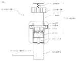
- FIG. 2 The configuration of the optical switch of the present disclosure is shown in FIG. 2, 10 is an optical switch, 100 is an optical drive rotary part, 110 is an optical expansion body, 112 is an optical fiber for optical switch drive, 115 is a knock bar, 120 is a rotating body, 200 is an optical switching rotary part, and 203.
- 206 is a switching target optical fiber
- 207 is a switching target optical fiber group
- 300 is a monitoring rotating part
- 301 is a first monitoring rotating body
- 306 is a monitoring transmitting optical fiber
- 307 is a monitoring receiving light.
- the optical switch 10 comprises an optical driving rotary part 100 and an optical switching rotary part 200 .
- a monitoring rotation unit 300 may be provided.
- the inside of the housing is seen through only within the dotted line of the light-driven rotating unit 100.
- FIG. 2 the inside of the housing is seen through only within the dotted line of the light-driven rotating unit 100.
- Driving light is applied to the optical expansion body 110 of the optical drive rotating unit 100 via the optical switch driving optical fiber 112, and then when the driving light is blocked, the light expands according to the irradiation/blocking.
- Body 110 expands and contracts.
- a knock rod 115 converts the expansion/contraction of the optical expander 110 into linear motion reciprocating by a fixed distance.
- a rotary motion body 120 in the light-driven rotary part 100 converts the linear motion of the knock rod 115 into a rotary motion that rotates by a predetermined angle.
- the rotation is transmitted to the optical switching rotating section 200, and the connection rotating body 203 in the optical switching rotating section 200 rotates, whereby one of the switching target optical fibers 207 and the switching target optical fiber 206 are switched and connected. be.
- the optical switch In the case where the optical switch is provided with the monitoring rotating part 300, when the rotating motion body 120 of the optically driven rotating part 100 is converted into a rotating motion that rotates by a certain angle, the rotation is transmitted to the monitoring rotating part 300, and the monitoring rotating part 300 rotates.
- a first monitoring rotor 300 rotates by a constant angle. Light is incident from the monitoring transmitting optical fiber 306 to the monitoring rotating section 300 , and the connection in the optical switching rotating section 200 depends on how the light is connected/blocked and incident on the monitoring receiving optical fiber 307 .
- the rotation angle of the rotor 203 can be detected. Therefore, the control device 20 can monitor whether the optical switch 10 switches and connects the switching target optical fiber 206 and which optical fiber in the switching target optical fiber group 207 as instructed.
- FIG. 3 shows the configuration of the light-driven rotation unit of the present disclosure.
- FIGS. 4 to 8B show the configurations of the optical expansion body, knock bar, cam, housing, and rotating body of the optically driven rotating portion of the present disclosure.
- 100 is an optical drive rotating part
- 110 is an optical expansion body
- 110-1 is an optical expansion member
- 111 is a lever
- 112 is an optical fiber for driving an optical switch
- 115 is a knock bar
- 115-1 is Knock bar groove
- 115-2 pressing portion 120 rotating body, 121 rotor, 122 rotor gear, 123 wings, 124 cam, 124-1 cam groove, 124-2 cam 125 is a projection
- 126 is an elastic body
- 127 is a shaft hole
- 140 is a housing
- 141 is a rotor hole
- 142 is a recess
- 143 is a knock hole of the housing.
- the inside of the housing 140 is seen through only within the dotted line of the light-driven rotation unit
- the optical expansion body 110 expands when it is irradiated with the driving light supplied from the optical switch driving optical fiber 112, and contracts when it is blocked.
- the material of the photoexpansion body 110 is a member that expands when light is irradiated and shrinks when the light is blocked.
- a material that easily expands includes polymer molecules.
- a black material, such as charcoal, is incorporated into an easily swellable material such as polymer molecules.
- the thermal expansion of air may be utilized by using an expandable polymer containing air bubbles therein.
- Fig. 4 shows an example of the configuration of the photoexpansion body. Because of the large change in thermal expansion, a lever 111 may be used to amplify the expansion and contraction of the optical expansion member 110-1, as shown in FIG.
- FIGS. 5A and 5B An example of the configuration of the knock bar is shown in FIGS. 5A and 5B.
- FIG. 5A is a front view, top view and bottom view of the knock bar
- FIG. 5B is a perspective view of the knock bar.
- the pressing portion 115-2 of the knock rod 115 linearly moves back and forth within the knock hole 124-2 of the cam by a certain distance in accordance with the expansion and contraction of the optical expansion body 110.
- the knock bar 115 has an annular knock bar groove 115-1 on the end face on the wing 123 side.
- Knock bar groove 115-1 has a serrated shape.
- the period of the groove 115-1 of the knock bar is the same as the groove 124-1 of the cam of the cam 124 and is shifted by half a pitch.
- the slope of the groove 115-1 of the knock bar receives the wing 123 when the rotor 121 is pushed up, so it has an inclination in the same direction as the slope of the wing 123.
- the rotating body 120 converts the linear motion of the knock rod 115 reciprocating by a constant distance into rotary motion rotating by a constant angle.
- the rotating body 120 has a rotor 121 , a rotor gear 122 , wings 123 , a cam 124 , a protrusion 125 , an elastic body 126 and a housing 140 .
- FIGS. 6A and 6B An example of cam configuration is shown in FIGS. 6A and 6B.
- FIG. 6A is a front view, top view and bottom view of the cam
- FIG. 6B is a perspective view of the cam.
- cam 124 has a cylindrical shape in which knock bar 115 reciprocates through knock hole 124-2 of the cam inside, and is fixed inside housing 140.
- An annular cam groove 124-1 is provided on the end face on the wing 123 side.
- the cam groove 124-1 has a sawtooth shape.
- the period of the cam grooves 124-1 is the same as that of the knock bar grooves 115-1, with a half pitch difference. Since the slope of the groove 124-1 of the cam receives the blade 123 of the rotor 121, it is inclined in the same direction as the slope of the blade 123.
- FIGS. 7A and 7B An example of the configuration of the housing is shown in FIGS. 7A and 7B.
- 7A is a front view, top view, and bottom view of the housing
- FIG. 7B is a perspective view of the housing.
- the housing 140 has rotor holes 141, recesses 142, and dowel holes 143 in the housing.
- the housing 140 supports the rotor 121 in the rotor hole 141 and stabilizes its rotational motion.
- Housing 140 secures cam 124 therein.
- the housing 140 supports the internal knock burs 115 in the housing's knock holes 143 to stabilize its linear motion.
- An elastic body 126 is fixed to a part of the housing 140 , and the elastic body 126 pushes the rotor 121 back toward the cam 124 .
- FIGS. 8A and 8B An example of the configuration of the rotary body is shown in FIGS. 8A and 8B.
- 8A is a front view, a top view, and a bottom view of the rotating body
- FIG. 8B is a perspective view of the rotating body.
- rotor 121 rotates around shaft hole 127 inside housing 140 .
- the rotor gear 122 is fixed to the side surface of the rotor 121 and transmits the rotation of the rotor 121 .
- the blade 123 is fixed to the end face of the rotor 121 on the knock rod 115 side, and the tip on the knock rod 115 side forms a flat slope.
- the slope of the blade 123 has the same inclination as the slope of the toothed knock bar groove 115-1 and the slope of the toothed cam groove 124-1. It is desirable that the inclination angle of the slope of the blade 123 is approximately the same as the inclination angle of the slope of the serrated knock rod groove 115-1 and the slope angle of the sawtooth cam groove 124-1.
- Rotor protrusion 125 has the same degree of freedom in the direction of linear movement of knock rod 115 within the internal width of recess 142 .
- FIG. 9, 10 and 11 100 is an optical drive rotating part
- 110 is an optical expansion body
- 112 is an optical switch driving optical fiber
- 115 is a knock bar
- 120 is a rotating body
- 121 is a rotor
- 122 is 123 is a wing
- 124 is a cam
- 125 is a convex portion
- 126 is an elastic body
- 140 is a housing. 9, 10, and 11, the interior of the housing 140 is seen through only within the dotted line of the light-driven rotating section 100. As shown in FIG.
- the optical expansion body 110 when the optical expansion body 110 is irradiated with driving light through the optical switch driving optical fiber 112, the optical expansion body 110 expands.
- the knock rod 115 advances toward the rotor 121 .
- the inclined surface of the groove 115-1 of the knock rod is pressed against the inclined surface of the blade 123, and the inclined surface of the pressed blade 123 slides on the inclined surface of the groove 115-1 of the knock rod, thereby rotating the rotor 121.
- FIGS. 12A and 12B The configuration of the optical switching rotating section is shown in FIGS. 12A and 12B.
- 12A is a front view, a top view, and a bottom view of the optical switching rotator
- FIG. 12B is a perspective view of the optical switching rotator.
- 200 is an optical switching rotating part
- 201 is a first optical connector
- 202 is a second optical connector
- 203 is a connection rotor
- 206 is an optical fiber to be switched
- 207 is a light to be switched.
- the fiber group, 213, is the connecting rotor gear.
- the optical switching rotating part 200 has a first optical connecting body 201, a second optical connecting body 202 and a connecting rotating body 203.
- One switching target optical fiber 206 is fixed to the first optical connector 201 .
- a plurality of optical fibers of the switching target optical fiber group 207 are fixed to the second optical connector 202 .
- the connecting rotating body 203 rotates about its axis in synchronization with the rotation of the rotating moving body 120, and connects one switching target optical fiber 206 fixed to the first optical connecting body 201 in contact with one end face.
- One optical fiber in the switching target optical fiber group 207 fixed to the second optical connector 202 in contact with the other end face is switched and connected.
- the number of teeth of the optical switching rotating part 200 in FIGS. 12A and 12B does not need to match the number of teeth of the rotating body 120 in FIG. 8A and the like.
- connection rotor 203 has a connection rotor gear 213 and a connection optical path (not shown).
- the connection rotor gear 213 rotates the connection rotor 203 about the axis in accordance with the rotational motion converted by the rotary motion body 120 . That is, the connection rotor gear 213 rotates the connection rotor 203 around the axis by the rotor gear 122 that transmits the rotation of the rotor 121 .
- the connection optical path is a connection point on a circle having a predetermined distance from the center of rotation of one end face perpendicular to the axis of the connection rotator 203 and the center of rotation of the other end face perpendicular to the axis. Connecting.
- the first optical connector 201 is in contact with one end face of the connection rotor 203 and fixes one switching target optical fiber 206 at a position facing the center of rotation of the connection rotor 203 .
- the second optical connector 202 is in contact with the other end face of the connection rotator 203 , and connects the plurality of optical fibers of the switching target optical fiber group 207 on a circle having a radius of a predetermined distance from the rotation center of the connection rotator 203 . fixed to As the connection rotor 203 rotates, the connection optical path of the connection rotor 203 changes between the single switchable optical fiber 206 of the first optical connector 201 and the switchable optical fiber group 207 of the second optical connector 202. is switched and connected to one of the optical fibers.
- a collimator lens may be provided at each end point of the connection optical path of one switching target optical fiber 206 and the connection rotator 203 to connect them with collimated light.
- a collimating lens may be provided at each of the end points of the optical fibers of the switching target optical fiber group 207 and the connecting optical path of the connecting rotor 203 to connect them with collimated light. Connection loss can be reduced by connecting with collimated light.
- the optical switch of the present disclosure can eliminate the need for power supply, and an optical switch system using the optical switch can operate with low power consumption.
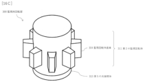
- FIGS. 13A, 13B and 13C The configuration of the monitoring rotation unit 300 is shown in FIGS. 13A, 13B and 13C.
- 13A is a front view, a top view, and a bottom view of the optical monitoring rotator
- FIG. 13B is a connection/interruption pattern of the monitoring optical path of the first monitoring rotator
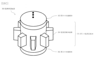
- FIG. 13C is a perspective view of the monitoring rotator.
- 300 is a monitoring rotating part
- 301 is a first monitoring rotating body
- 302 is a third optical connecting body
- 303 is a fourth optical connecting body
- 304 is a monitoring rotating body gear.
- 306 is a transmission optical fiber for monitoring
- 307 is a reception optical fiber for monitoring.
- the first monitoring rotating body 301 rotates in synchronization with the rotation of the rotating moving body 120, and detects the rotation angle of the connecting rotating body 203.
- 13A, 13B, and 13C does not necessarily have to match the number of teeth of the rotating body 120 shown in FIG. 8A.
- the monitoring rotating section 300 has a first monitoring rotating body 301 , a third optical connecting body 302 , a fourth optical connecting body 303 and a monitoring rotating body gear 304 .
- the first monitoring rotor 301 has a plurality of monitoring optical paths (not shown) connecting one end surface perpendicular to the axis and the other end surface perpendicular to the axis.
- the first monitoring rotating body 301 rotates about its axis in accordance with the rotating motion converted by the rotating moving body 120 . Rotational motion is imparted by monitor rotor gear 304 which imparts rotation of rotor 121 .
- the connection/interruption pattern of the monitoring optical path differs depending on the rotation angle of the first monitoring rotor 301 .
- the third optical connector 302 is in contact with one end surface of the first monitoring rotor 301 and fixes a plurality of monitoring transmission optical fibers 306 for transmitting monitoring light.
- the fourth optical connector 303 is in contact with the other end face of the first monitoring rotor 301 and fixes a plurality of monitoring receiving optical fibers 307 for receiving monitoring light.
- a collimating lens may be provided at each end point of the monitoring optical path of the transmission optical fiber 306 for monitoring and the first monitoring rotator 301 to connect them with collimated light. Further, a collimating lens may be provided at each end point of the monitoring optical path of the receiving optical fiber 307 for monitoring and the first monitoring rotator 301 to connect them with collimated light. Connection loss can be reduced by connecting with collimated light.
- the rotation of the first monitoring rotating body 301 uniquely changes the light connection/interruption pattern from the plurality of monitoring transmission optical fibers 306 to the plurality of monitoring reception optical fibers 307 .
- the first monitoring rotator 301 is each divided into 8 divisions in 45 degree units in the rotational direction of the shaft. In the case of units of 45 degrees, it is divided into eight of 0, 45, 90, 135, 180, 225, 270 and 315 degrees.
- Three optical fibers are used as the monitoring transmission optical fibers 306 , and the three monitoring transmission optical fibers 306 are fixed at the 0 degree position on the end surface of the third optical connector 302 .
- the first monitoring rotator 301 uniquely differs in connection and disconnection patterns between the three monitoring transmission optical fibers 306 and the three monitoring reception optical fibers 307 depending on the rotation angle.
- the patterns of connection and disconnection from the three monitoring transmission optical fibers 306 to the three monitoring reception optical fibers 307 uniquely change.
- the first monitoring rotor 301 is divided into 36 units of 10 degrees in order to monitor 36 states, and the first monitoring rotor 301 has six monitoring optical paths. 6 transmission optical fibers 306 for monitoring and 6 reception optical fibers 307 for monitoring are also required. The number of monitoring optical paths of the first monitoring rotator 301 and the number of monitoring transmitting optical fibers 306 and monitoring receiving optical fibers 307 may be determined according to the rotation angle unit to be detected.
- the first monitoring rotor 301 is synchronized with the rotation of the rotor 121, and the connection rotor 203 is also synchronized with the rotation of the rotor 121. Therefore, the rotation angle of the connection rotator 203 can be known from the rotation angle detected by the monitoring rotation unit 300 , and as a result, the optical switching rotation unit 200 detects which of the switching target optical fiber 206 and the switching target optical fiber group 207 . It is possible to monitor whether the optical fiber is connected.
- the optical switch of the present disclosure that includes the monitoring rotation unit can eliminate the need for power supply, and the optical switch system using the optical switch can operate with low power consumption.
- FIG. 14 Another configuration of the optical switch system of the present disclosure is shown in FIG. 14, 10 is an optical switch, 112 is an optical fiber for driving the optical switch, 20 is a controller, 21 is a control unit, 22 is a light source for driving, 23 is a light source for monitoring, 24 is an optical receiver for monitoring, and 25 is A circulator, 206 an optical fiber to be switched, 207 an optical fiber group to be switched, and 308 a transmission/reception optical fiber for monitoring.
- the optical switch system includes an optical switch 10 and a control device 20.
- the control device 20 has a control unit 21 , a driving light source 22 , a monitoring light source 23 , a monitoring optical receiver 24 and a circulator 25 .
- the difference from the optical switch system of FIG. 1 is that the controller 20 further has a circulator 25 and uses a monitoring transmission/reception optical fiber 308 for monitoring the optical switch 10 .
- the control unit 21 causes the monitoring light source 23 to transmit monitoring light.
- the monitoring light source 23 supplies monitoring light to the optical switch 10 through the circulator 25 and the monitoring transmission/reception optical fiber 308 .
- the monitoring optical receiver 24 receives the monitoring light from the optical switch 10 via the monitoring transmitting/receiving optical fiber 308 and the circulator 25 .
- the control unit 21 receives a received signal from the monitoring optical receiver 24 and monitors whether the optical switch 10 operates as instructed.
- FIG. 15 Another configuration of the optical switch of the present disclosure is shown in FIG. 15, 10 is an optical switch, 100 is an optical drive rotary part, 110 is an optical expansion body, 112 is an optical fiber for optical switch drive, 115 is a knock bar, 120 is a rotating body, 200 is an optical switching rotary part, and 203.
- 206 is an optical fiber to be switched; 207 is a group of optical fibers to be switched; 300 is a monitoring rotator; 311 is a second monitoring rotator;
- the optical driving rotating section 100 and the optical switching rotating section have the same configuration as the optical switch in FIG.
- the configuration of the monitor rotating unit 300 is different from that of the optical switch in FIG. In FIG. 15 , the inside of the housing 140 is seen through only within the dotted line of the light-driven rotation unit 100 .
- the optical switch monitoring rotator 300 when a component in the optically driven rotator 100 rotates by a certain angle, the rotation is transmitted to the monitoring rotator 300, and the second monitor rotator of the monitoring rotator 300 rotates. 311 rotates by a certain angle.
- Light is incident on the monitoring rotating unit 300 from the monitoring transmitting/receiving optical fiber 308 , and depending on how the light is reflected/blocked and re-incident to the monitoring transmitting/receiving optical fiber 308 , the inside of the optical switching rotating unit 200 .
- the rotation angle of the connection rotor 203 can be detected. Therefore, the control device 20 can monitor whether the optical switch 10 connects/disconnects the switching target optical fiber 206 and which optical fiber in the switching target optical fiber group 207 as instructed.
- FIGS. 16A, 16B and 16C The configuration of the monitoring rotation unit 300 is shown in FIGS. 16A, 16B and 16C.
- 16A is a front view, a top view, and a bottom view of the optical monitoring rotator
- FIG. 16B is a reflection/blocking pattern of the second monitoring rotator
- FIG. 16C is a perspective view of the monitoring rotator.
- 300 is a monitoring rotator
- 311 is a second monitoring rotator
- 313 is a fifth optical connector
- 304 is a monitoring rotator gear
- 308 is a transmission/reception optical fiber for monitoring. be.
- the monitoring rotating section 300 rotates in synchronization with the rotation of the rotating body 120 and detects the rotation angle of the rotating body 120 .
- the number of teeth of the monitoring rotator 300 in FIGS. 16A, 16B, and 16C does not need to match the number of teeth of the rotating body 120 in FIG. 8A and the like.
- the second monitoring rotating body 311 rotates in synchronization with the rotation of the rotating moving body 120, and detects the rotation angle of the connecting rotating body 203.
- the monitoring rotator 300 has a second monitoring rotator 311 , a fifth optical connector 313 and a monitoring rotator gear 304 .
- the second monitoring rotating body 311 has a reflecting plate with a plurality of reflecting/blocking portions (not shown) on one end face perpendicular to the axis.
- the second monitoring rotating body 311 rotates about its axis according to the rotating motion converted by the rotating moving body 120 .
- Rotational motion is imparted by monitor rotor gear 304 which imparts rotation of rotor 121 .
- the reflection/blocking pattern differs depending on the angle of rotation of the second monitoring rotor 311 .
- the fifth optical connector 313 is in contact with one end surface of the second monitoring rotator 311, and fixes a plurality of monitoring transmitting/receiving optical fibers 308 for transmitting/receiving monitoring light.
- a collimating lens may be provided at the end point of the transmission/reception optical fiber 308 for monitoring to reflect/block the collimated light. Connection loss can be reduced by connecting with collimated light.
- the rotation of the second monitoring rotating body 311 uniquely changes the reflection/blocking pattern of the light from the plurality of monitoring transmitting/receiving optical fibers 308 .
- the second monitoring rotator 311 is each divided into 8 divisions in 45 degree units in the rotational direction of the shaft. In the case of units of 45 degrees, it is divided into eight of 0, 45, 90, 135, 180, 225, 270 and 315 degrees.
- Three optical fibers are used as the monitoring transmitting/receiving optical fibers 308 , and the three monitoring transmitting/receiving optical fibers 308 are fixed at the 0 degree position on the end surface of the fifth optical connector 313 .
- the second monitor rotator 311 uniquely differs in the pattern of reflection and interception with respect to the three monitoring transmitting/receiving optical fibers 308 depending on the rotation angle.
- the pattern of reflection and interception uniquely changes for the three monitoring transmission/reception optical fibers 308 .
- Denoting reflection as 1 and blocking as 0, and black circles as '1' and white circles as '0' in FIG. 8 patterns of 111, 011, 101, 001, 110, 010, 100, 000 ( 3 bits) can be detected for each part.
- the monitoring light from the monitoring transmitting/receiving optical fibers 308 is reflected by a mirror in the second monitoring rotating body 311, and the monitoring light is reflected. It may be returned to the transmission/reception optical fiber 308 for monitoring.
- the monitoring light from the monitoring transmitting/receiving optical fibers 308 may be non-reflected or absorbed by the second monitoring rotating body 311, or the monitoring light may be absorbed.
- the monitoring light may be reflected in a different direction from the transmitting/receiving optical fiber 308 so as not to return the monitoring light to the transmitting/receiving optical fiber 308 for monitoring.
- the second monitoring rotor 311 is synchronized with the rotation of the rotor 121, and the connection rotor 203 is also synchronized with the rotation of the rotor 121. Therefore, the rotation angle of the connection rotator 203 can be known from the rotation angle detected by the monitoring rotation unit 300 , and as a result, the optical switching rotation unit 200 detects which of the switching target optical fiber 206 and the switching target optical fiber group 207 . It is possible to monitor whether the optical fiber is connected.
- the optical switch of the present disclosure that includes a monitoring rotation unit can eliminate the need for power supply, and an optical switch system using the optical switch can operate with low power consumption.
- This disclosure can be applied to the communications industry.
- Optical switch 20 Control device 21: Control unit 22: Driving light source 23: Monitoring light source 24: Monitoring optical receiver 25: Circulator 100: Optical drive rotation unit 110: Optical expansion body 110-1: Optical expansion member 111: Lever 112: Optical fiber for driving optical switch 115: Knock rod 115-1: Knock rod groove 115-2: Pressing part 120: Rotating body 121: Rotor 122: Rotor gear 123: Blade 124: Cam 124 -1: Cam groove 124-2: Cam knock hole 125: Convex part 126: Elastic body 127: Shaft hole 140: Case 141: Rotor hole 142: Concave part 143: Case knock hole 200: Optical switching rotation Part 201: First optical connector 202: Second optical connector 203: Connection rotor 206: Switching target optical fiber 207: Switching target optical fiber group 213: Connection rotor gear 300: Monitoring rotating part 301: Third 1 monitoring rotator 302: third optical connector 303: fourth optical connector 304: monitoring
Landscapes
- Physics & Mathematics (AREA)
- General Physics & Mathematics (AREA)
- Optics & Photonics (AREA)
- Mechanical Light Control Or Optical Switches (AREA)
Abstract
本開示は、電力の供給を不要とする光スイッチの提供を目的とする。 本開示は、光の照射によって膨張し、光の遮断によって縮小する光膨張体、前記光膨張体の膨張・縮小を一定距離だけ往復する直線運動に変換するノック棒、及び前記ノック棒の一定距離だけ往復する直線運動に応じて一定の角度だけ回転する回転運動に変換する回転運動体を有する光駆動回転部と、1本の切替対象光ファイバが固定された第1の光接続体、切替対象光ファイバ群の光ファイバがそれぞれ固定された第2の光接続体、及び前記回転運動体の変換する回転に同期して軸を中心に回転し、一方の端面に接する前記第1の光接続体に固定された1本の切替対象光ファイバと他方の端面に接する前記第2の光接続体に固定された切替対象光ファイバ群の中の1本の光ファイバとを切替接続する接続回転体を有する光スイッチング回転部と、を備える光スイッチである。
Description
本開示は、光経路の切替えに用いる光スイッチ及び光スイッチシステムに関する。
光を光のまま経路切替を行う全光スイッチは様々な方式が提案されている(例えば、非特許文献1参照。)。このうち、光ファイバあるいは光コネクタ同士の突合せをロボットアームやモータ等で制御する光ファイバ型機械式光スイッチは、切替速度が遅いという点では他方式に劣るものの、低損失、低波長依存性、多ポート性、電源消失時に切替状態を保持する自己保持機能の具備などの点で他方式よりも優れている点を多く有している。
この代表的な構造として、例えば、光ファイバV溝を用いたステージを並行移動させる方式や、ミラーやプリズムを並行移動または角度変化させて入射光ファイバから複数の出射光ファイバに対して選択的に結合させる方式、ロボットアームを用いて光コネクタ付きのジャンパーケーブルを接続する方式などがある。
M.Stepanovsky,"A Comparative Review of MEMS-Based Optical Cross-Connects for All-Optical Networks From the Past to the Present Day," IEEE Communications Surveys & Tutorials,vоl.21,nо.3,pp.2928-2946,2019.
しかしながら、前述の非特許文献1に記載の従来技術においては、さらなる低電力化および小型化、経済化が困難であるという問題がある。具体的には、前述の光ファイバV溝ステージあるいはプリズムを並行移動させる方式では、一般に駆動源にモータが用いられるが、ステージ等の重量物を直動させる機構のため、一定以上のトルクがモータに必要となり、必要トルクを維持するために相応の出力を得るための消費電力を要する。
また、シングルモード光ファイバを用いた光軸調心には、1μm以下程度の精度が必要であることから、モータの回転運動を直動運動に変換させる機構、例えば、ボールねじを用いると、サブμmステップの直動運動に変換させる必要がある。通常用いられる出力側の光ファイバアレイの光ファイバピッチが光ファイバのクラッド外径125μmあるいは光ファイバの被覆外径250μm程度である。
この光ファイバピッチを維持したまま設置する光ファイバの本数を多くすると、出力側の光ファイバアレイが大きくなる。その結果、直動運動の距離が延び、モータの実駆動時間は長くせざるを得ず、消費電力が増大するという課題があった。このため、このような光ファイバ型機械式光スイッチは数百mW以上の電力を要する。また、光コネクタを用いたロボットアーム方式は、光コネクタあるいはフェルールを挿抜制御するロボットアームそのものに数十W以上の大きな電力を要してしまうという課題があった。屋外の架空光接続点など、電力供給の困難な環境においては、これらの光スイッチを駆動させるのに十分な電力を確保することは困難であった。
そこで、前述の課題を解決するために、本開示は、電力の供給を不要とする光スイッチ、及び当該光スイッチを利用して低消費電力で動作する光スイッチシステムの提供を目的とする。
前記課題を解決するために、本開示の光スイッチは、光の照射・遮断で膨張・縮小する光膨張体を利用して、直線運動から回転運動を発生させ、回転運動で光ファイバを切替接続する構成とした。
具体的には、本開示は
光の照射によって膨張し、光の遮断によって縮小する光膨張体、
前記光膨張体の膨張・縮小を一定距離だけ往復する直線運動に変換するノック棒、
及び前記ノック棒の一定距離だけ往復する直線運動に応じて一定の角度だけ回転する回転運動に変換する回転運動体
を有する光駆動回転部と、
1本の切替対象光ファイバが固定された第1の光接続体、
切替対象光ファイバ群の光ファイバがそれぞれ固定された第2の光接続体、
及び前記回転運動体の変換する回転に同期して軸を中心に回転し、一方の端面に接する前記第1の光接続体に固定された1本の切替対象光ファイバと他方の端面に接する前記第2の光接続体に固定された切替対象光ファイバ群の中の1本の光ファイバとを切替接続する接続回転体
を有する光スイッチング回転部と、
を備える光スイッチ
である。
光の照射によって膨張し、光の遮断によって縮小する光膨張体、
前記光膨張体の膨張・縮小を一定距離だけ往復する直線運動に変換するノック棒、
及び前記ノック棒の一定距離だけ往復する直線運動に応じて一定の角度だけ回転する回転運動に変換する回転運動体
を有する光駆動回転部と、
1本の切替対象光ファイバが固定された第1の光接続体、
切替対象光ファイバ群の光ファイバがそれぞれ固定された第2の光接続体、
及び前記回転運動体の変換する回転に同期して軸を中心に回転し、一方の端面に接する前記第1の光接続体に固定された1本の切替対象光ファイバと他方の端面に接する前記第2の光接続体に固定された切替対象光ファイバ群の中の1本の光ファイバとを切替接続する接続回転体
を有する光スイッチング回転部と、
を備える光スイッチ
である。
このような構造とすることにより、本開示の光スイッチは、電力の供給を不要とする構成とすることができる。
また、本開示の光スイッチは、
前記回転運動体は、
筐体の内部で軸を中心に回転する回転子、
前記回転子の側面に固定され、前記回転子の回転を伝える回転子歯車、
前記回転子の前記ノック棒の側の端面に固定され、前記ノック棒の側の先端が平坦な斜面となっている羽、
前記筐体の内部に固定され、円筒状の前記羽の側の端面に円環状に設けられた鋸歯状の溝の斜面であって前記羽の斜面と同じ方向の傾きを持つ斜面で前記羽の斜面を受け止める円筒状のカム、
及び前記筐体に固定され、前記回転子を前記カムに向かって押し返す弾性体
を有し、
前記ノック棒は、前記カムの円筒状内部を往復し、前記カムの鋸歯状の溝と同じ周期で半ピッチずれた鋸歯状の溝であって、斜面が前記羽の斜面と同じ方向の傾きの斜面を持つ溝を前記羽の側の端面に円環状に有し、
前記光膨張体が縮小している際は、前記羽の斜面が前記弾性体によって前記カムの鋸歯状の溝の斜面に押し当てられ、
前記光膨張体が膨張する際は、前記ノック棒が前記回転子に向かって前進して、前記ノック棒の鋸歯状の溝の斜面が前記羽の斜面に押し当てられ、押し当てられた前記羽の斜面が前記ノック棒の鋸歯状の歯の斜面を滑ることによって、前記回転子が回転し、
前記光膨張体が膨張から縮小に転じる際は、前記ノック棒が前記回転子から後退し、前記弾性体によって押し返された前記回転子が前記カムに向かい、前記羽の斜面が前記カムの鋸歯状の溝の斜面に押し当てられ、押し当てられた前記羽の斜面が前記カムの鋸歯状の歯の斜面を滑ることによって、前記回転子が回転する
ことを特徴とする。
前記回転運動体は、
筐体の内部で軸を中心に回転する回転子、
前記回転子の側面に固定され、前記回転子の回転を伝える回転子歯車、
前記回転子の前記ノック棒の側の端面に固定され、前記ノック棒の側の先端が平坦な斜面となっている羽、
前記筐体の内部に固定され、円筒状の前記羽の側の端面に円環状に設けられた鋸歯状の溝の斜面であって前記羽の斜面と同じ方向の傾きを持つ斜面で前記羽の斜面を受け止める円筒状のカム、
及び前記筐体に固定され、前記回転子を前記カムに向かって押し返す弾性体
を有し、
前記ノック棒は、前記カムの円筒状内部を往復し、前記カムの鋸歯状の溝と同じ周期で半ピッチずれた鋸歯状の溝であって、斜面が前記羽の斜面と同じ方向の傾きの斜面を持つ溝を前記羽の側の端面に円環状に有し、
前記光膨張体が縮小している際は、前記羽の斜面が前記弾性体によって前記カムの鋸歯状の溝の斜面に押し当てられ、
前記光膨張体が膨張する際は、前記ノック棒が前記回転子に向かって前進して、前記ノック棒の鋸歯状の溝の斜面が前記羽の斜面に押し当てられ、押し当てられた前記羽の斜面が前記ノック棒の鋸歯状の歯の斜面を滑ることによって、前記回転子が回転し、
前記光膨張体が膨張から縮小に転じる際は、前記ノック棒が前記回転子から後退し、前記弾性体によって押し返された前記回転子が前記カムに向かい、前記羽の斜面が前記カムの鋸歯状の溝の斜面に押し当てられ、押し当てられた前記羽の斜面が前記カムの鋸歯状の歯の斜面を滑ることによって、前記回転子が回転する
ことを特徴とする。
また、本開示の光スイッチは、
前記光膨張体は、黒色の材料又は内部に気泡を含む材料で構成されている
ことを特徴とする。
前記光膨張体は、黒色の材料又は内部に気泡を含む材料で構成されている
ことを特徴とする。
また、本開示の光スイッチは、
前記接続回転体は、
前記回転運動体の変換する回転運動に応じて、軸を中心に回転させる接続回転体歯車、
及び軸に垂直な一方の端面の回転の中心と軸に垂直な他方の端面の回転の中心から所定距離を半径とする円周上に配置された接続点とを接続する接続光路
を有し、
前記第1の光接続体は、前記接続回転体の一方の端面に接し、前記1本の切替対象光ファイバを前記接続回転体の回転の中心に対向する位置に固定し、
前記第2の光接続体は、前記接続回転体の他方の端面に接し、前記切替対象光ファイバ群の光ファイバを前記接続回転体の回転の中心から所定距離を半径とする円周上にそれぞれ固定し、
前記接続回転体が回転することによって、前記接続光路が前記第1の光接続体の前記1本の切替対象光ファイバと前記第2の光接続体の前記切替対象光ファイバ群の中の1本の光ファイバとを切替接続する
ことを特徴とする。
前記接続回転体は、
前記回転運動体の変換する回転運動に応じて、軸を中心に回転させる接続回転体歯車、
及び軸に垂直な一方の端面の回転の中心と軸に垂直な他方の端面の回転の中心から所定距離を半径とする円周上に配置された接続点とを接続する接続光路
を有し、
前記第1の光接続体は、前記接続回転体の一方の端面に接し、前記1本の切替対象光ファイバを前記接続回転体の回転の中心に対向する位置に固定し、
前記第2の光接続体は、前記接続回転体の他方の端面に接し、前記切替対象光ファイバ群の光ファイバを前記接続回転体の回転の中心から所定距離を半径とする円周上にそれぞれ固定し、
前記接続回転体が回転することによって、前記接続光路が前記第1の光接続体の前記1本の切替対象光ファイバと前記第2の光接続体の前記切替対象光ファイバ群の中の1本の光ファイバとを切替接続する
ことを特徴とする。
また、本開示の光スイッチは、
前記回転運動体の回転に同期して回転し、前記接続回転体の回転角度を検出する監視用回転部をさらに備える
ことを特徴とする。
前記回転運動体の回転に同期して回転し、前記接続回転体の回転角度を検出する監視用回転部をさらに備える
ことを特徴とする。
また、本開示の光スイッチは、
前記監視用回転部は、
前記回転運動体の変換する回転運動に応じて、軸を中心に回転し、軸に垂直な一方の端面と軸に垂直な他方の端面とを接続する複数の監視光路であって、回転の角度によって接続・遮断のパターンが異なる監視光路を有する第1の監視回転体と、
前記第1の監視回転体の一方の端面に接し、監視用の光を送信する複数の監視用送信光ファイバを固定する第3の光接続体と、
前記第1の監視回転体の他方の端面に接し、監視用の光を受信する複数の監視用受信光ファイバを固定する第4の光接続体と、を有し、
前記第1の監視回転体の回転によって、前記複数の監視用送信光ファイバから前記複数の監視用受信光ファイバへのそれぞれの光の接続・遮断のパターンが固有に変化する
ことを特徴とする。
前記監視用回転部は、
前記回転運動体の変換する回転運動に応じて、軸を中心に回転し、軸に垂直な一方の端面と軸に垂直な他方の端面とを接続する複数の監視光路であって、回転の角度によって接続・遮断のパターンが異なる監視光路を有する第1の監視回転体と、
前記第1の監視回転体の一方の端面に接し、監視用の光を送信する複数の監視用送信光ファイバを固定する第3の光接続体と、
前記第1の監視回転体の他方の端面に接し、監視用の光を受信する複数の監視用受信光ファイバを固定する第4の光接続体と、を有し、
前記第1の監視回転体の回転によって、前記複数の監視用送信光ファイバから前記複数の監視用受信光ファイバへのそれぞれの光の接続・遮断のパターンが固有に変化する
ことを特徴とする。
また、本開示の光スイッチは、
前記監視用回転部は、
前記回転運動体の変換する回転運動に応じて、軸を中心に回転し、軸に垂直な一方の端面に回転の角度によって反射・遮断のパターンが異なる反射板を有する第2の監視回転体と、
前記第2の監視回転体の一方の端面に接し、監視用の光を送受信する複数の監視用送受信光ファイバを固定する第5の光接続体と、を有し、
前記第2の監視回転体の回転によって、前記複数の監視用送受信光ファイバでのそれぞれの光の反射・無反射のパターンが固有に変化する
ことを特徴とする。
前記監視用回転部は、
前記回転運動体の変換する回転運動に応じて、軸を中心に回転し、軸に垂直な一方の端面に回転の角度によって反射・遮断のパターンが異なる反射板を有する第2の監視回転体と、
前記第2の監視回転体の一方の端面に接し、監視用の光を送受信する複数の監視用送受信光ファイバを固定する第5の光接続体と、を有し、
前記第2の監視回転体の回転によって、前記複数の監視用送受信光ファイバでのそれぞれの光の反射・無反射のパターンが固有に変化する
ことを特徴とする。
前記課題を解決するために、本開示の光スイッチシステムは、制御装置からの光の照射・遮断で膨張・縮小する光膨張体を利用して、直線運動から回転運動を発生させ、回転運動で光ファイバを切替接続する構成とした。
具体的には、本開示は
前記いずれかに記載の光スイッチと、
前記光膨張体に膨張を起こさせる光を供給する駆動用光源及び前記駆動用光源に照射、遮断を指示する制御部を有する制御装置と、
を備えることを特徴とする光スイッチシステム
である。
前記いずれかに記載の光スイッチと、
前記光膨張体に膨張を起こさせる光を供給する駆動用光源及び前記駆動用光源に照射、遮断を指示する制御部を有する制御装置と、
を備えることを特徴とする光スイッチシステム
である。
このような構造とすることにより、本開示の光スイッチシステムは、電力の供給を不要とする光スイッチを利用するため、低消費電力で動作するすることができる。
なお、上記各開示の発明は、可能な限り組み合わせることができる。
本開示によれば、電力の供給を不要とし、低消費電力で動作する光スイッチ及び当該光スイッチを利用した光スイッチシステムを提供することができる。
以下、本開示の実施形態について、図面を参照しながら詳細に説明する。なお、本開示は、以下に示す実施形態に限定されるものではない。これらの実施の例は例示に過ぎず、本開示は当業者の知識に基づいて種々の変更、改良を施した形態で実施することができる。なお、本明細書及び図面において符号が同じ構成要素は、相互に同一のものを示すものとする。
本開示の光スイッチシステムの構成を図1に示す。図1において、10は光スイッチ、112は光スイッチ駆動用光ファイバ、20は制御装置、21は制御部、22は駆動用光源、23は監視用光源、24は監視用光受信機、206は切替対象光ファイバ、207は切替対象光ファイバ群、306は監視用送信光ファイバ、307は監視用受信光ファイバである。
光スイッチシステムは、光スイッチ10及び制御装置20を備える。制御装置20は、制御部21及び駆動用光源22を有する。制御装置20は、監視用光源23及び監視用光受信機24をさらに有してもよい。
制御部21は、駆動用光源22に駆動用の光の照射・遮断を指示する。駆動用光源22は光スイッチ駆動用光ファイバ112を通して、光スイッチ10に駆動用の光を供給する。駆動用光源22の光を照射・遮断とすることにより、光スイッチ10は、切替対象光ファイバ206と切替対象光ファイバ群207の中の1本の光ファイバとを切替接続する。光スイッチ10は電源を用いておらず、電源を使用することができる制御装置20から光スイッチ駆動用光ファイバ112を介して送られる光により制御される。
制御部21は、監視用光源23に監視用の光を送信させる。監視用光源23は監視用送信光ファイバ306を通して、光スイッチ10に監視用の光を供給する。監視用光受信機24は監視用受信光ファイバ307を通して、光スイッチ10から監視用の光を受信する。制御部21は、監視用光受信機24からの受信信号を受信し、光スイッチ10が指示通りに動作しているかを監視する。
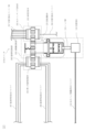
本開示の光スイッチの構成を図2に示す。図2において、10は光スイッチ、100は光駆動回転部、110は光膨張体、112は光スイッチ駆動用光ファイバ、115はノック棒、120は回転運動体、200は光スイッチング回転部、203は接続回転体、206は切替対象光ファイバ、207は切替対象光ファイバ群、300は監視用回転部、301は第1の監視回転体、306は監視用送信光ファイバ、307は監視用受信光ファイバである。光スイッチ10は光駆動回転部100及び光スイッチング回転部200を備える。さらに、監視用回転部300を備えてもよい。なお、図2では、光駆動回転部100の点線内だけ、筐体の内部を透視した図面としている。
光スイッチ駆動用光ファイバ112を介して、光駆動回転部100の光膨張体110に駆動用の光が照射され、その後、駆動用の光が遮断されると、照射・遮断に応じて光膨張体110が膨張・縮小する。ノック棒115が光膨張体110の膨張・縮小を一定距離だけ往復する直線運動に変換する。光駆動回転部100の中の回転運動体120がノック棒115の直線運動を一定角度だけ回転する回転運動に変換する。その回転が光スイッチング回転部200に伝わり、光スイッチング回転部200の中の接続回転体203が回転することにより、切替対象光ファイバ群207の中の1本と切替対象光ファイバ206が切替接続される。
光スイッチが監視用回転部300を備える場合は、光駆動回転部100の回転運動体120が一定角度だけ回転する回転運動に変換すると、その回転が監視用回転部300へ伝わり、監視用回転部300の第1の監視回転体が一定角度回転する。監視用送信光ファイバ306から監視用回転部300へ光が入射され、その光がどのように接続・遮断されて監視用受信光ファイバ307へ入射されるかにより光スイッチング回転部200の中の接続回転体203の回転角度を検出することができる。従って、制御装置20は、光スイッチ10が、切替対象光ファイバ206と切替対象光ファイバ群207の中のどの光ファイバとを指示通りに切替接続しているかを監視することができる。
本開示の光駆動回転部の構成を図3に示す。本開示の光駆動回転部の有する光膨張体、ノック棒、カム、筐体及び回転運動体の各構成を図4から図8Bに示す。図3から図8Bにおいて、100は光駆動回転部、110は光膨張体、110-1は光膨張部材、111はテコ、112は光スイッチ駆動用光ファイバ、115はノック棒、115-1はノック棒の溝、115-2は押圧部、120は回転運動体、121は回転子、122は回転子歯車、123は羽、124はカム、124-1はカムの溝、124-2はカムのノック孔、125は凸部、126は弾性体、127は軸孔、140は筐体、141は回転子孔、142は凹部、143は筐体のノック孔である。なお、図3では、光駆動回転部100の点線内だけ、筐体140の内部を透視した図面としている。
図3において、光膨張体110は、光スイッチ駆動用光ファイバ112から供給される駆動用の光が照射されると膨張し、遮断されると縮小する。光膨張体110の材料は光が照射されると膨張し、光が遮断されると縮小する部材である。例えば、膨張しやすい材料として、ポリマー分子が挙げられる。ポリマー分子などの膨張しやすい材料に黒色の材料、例えば、炭が練り込まれていることが望ましい。その黒色物質が光を照射されることで光を熱に変換することが容易になる。その熱を黒色物質のポリマーに移動することで、ポリマーが熱膨張を起こす。また、内部に気泡を含む発泡性のポリマーを使って空気の熱膨張を利用してもよい。
光膨張体の構成の例を図4に示す。熱膨張で大きな変化を起こすため、図4に示すように、テコ111を用いて光膨張部材110-1の膨張・縮小を増幅してもよい。
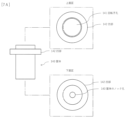
ノック棒の構成の例を図5A及び図5Bに示す。図5Aはノック棒の正面図、上面図及び下面図であり、図5Bはノック棒の斜視図である。図3、図5A及び図5Bにおいて、ノック棒115の押圧部115-2は、光膨張体110の膨張・縮小に合わせて、カムのノック孔124-2の内部を一定距離だけ往復する直線運動に変換する。具体的には、ノック棒115は、羽123の側の端面に、円環状にノック棒の溝115-1を有する。ノック棒の溝115-1は鋸歯状の形状を持つ。ノック棒の溝115-1の周期は、カム124のカムの溝124-1と同じで、半ピッチずれている。ノック棒の溝115-1の斜面は回転子121を押し上げる際に羽123を受け止めるため、羽123の斜面と同じ方向の傾きを持つ。
回転運動体120は、ノック棒115の一定距離だけ往復する直線運動に応じて一定の角度だけ回転する回転運動に変換する。具体的には、回転運動体120は、回転子121、回転子歯車122、羽123、カム124、凸部125、弾性体126及び筐体140を有する。
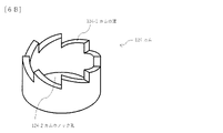
カムの構成の例を図6A及び図6Bに示す。図6Aはカムの正面図、上面図及び下面図であり、図6Bはカムの斜視図である。図3、図6A及び図6Bにおいて、カム124は、内部のカムのノック孔124-2をノック棒115が往復する円筒状で、筐体140の内部に固定されている。羽123の側の端面に、円環状にカムの溝124-1を有する。カムの溝124-1は鋸歯状の形状を持つ。カムの溝124-1の周期は、ノック棒の溝115-1と同じで、半ピッチずれている。カムの溝124-1の斜面は回転子121の羽123を受け止めるため、羽123の斜面と同じ方向の傾きを持つ。
筐体の構成の例を図7A及び図7Bに示す。図7Aは筐体の正面図、上面図及び下面図であり、図7Bは筐体の斜視図である。図3、図7A及び図7Bにおいて、筐体140は、回転子孔141、凹部142及び筐体のノック孔143を持つ。筐体140は、回転子孔141で回転子121を支え、その回転運動を安定化する。筐体140は、内部にカム124を固定する。筐体140は、筐体のノック孔143で内部のノック俸115を支え、その直線運動を安定化する。筐体140の一部には、弾性体126が固定され、弾性体126は回転子121をカム124に向かって押し返す。
回転運動体の構成の例を図8A及び図8Bに示す。図8Aは回転運動体の正面図、上面図及び下面図であり、図8Bは回転運動体の斜視図である。図3、図8A及び図8Bにおいて、回転子121は、筐体140の内部で、軸孔127を中心に回転する。回転子歯車122は、回転子121の側面に固定され、回転子121の回転を伝える。羽123は、回転子121のノック棒115の側の端面に固定され、ノック棒115の側の先端が平坦な斜面となっている。羽123の斜面は、鋸歯状のノック棒の溝115-1の斜面及び鋸歯状のカムの溝124-1の斜面と同じ方向の傾きを持つ。羽123の斜面の傾きの角度も鋸歯状のノック棒の溝115-1の斜面の傾きの角度及び鋸歯状のカムの溝124-1の斜面の傾きの角度と同程度が望ましい。回転子の凸部125は、凹部142の内部広さの範囲内でノック棒115の直線運動と同じ方向の自由度を持つ。
光駆動回転部100の動作を図9、図10及び図11で説明する。図9、図10及び図11において、100は光駆動回転部、110は光膨張体、112は光スイッチ駆動用光ファイバ、115はノック棒、120は回転運動体、121は回転子、122は回転子歯車、123は羽、124はカム、125は凸部、126は弾性体、140は筐体である。なお、図9、図10及び図11では、光駆動回転部100の点線内だけ、筐体140の内部を透視した図面としている。
図9において、光膨張体110に光が照射されていないときは、光膨張体110は縮小している。光膨張体110が縮小していると、ノック棒115は羽123から離れている。弾性体126が回転子121を押すことによって、羽123の斜面がカムの溝124-1の斜面に押し当てられている。
図10において、光スイッチ駆動用光ファイバ112を通して光膨張体110に駆動用の光が照射されると、光膨張体110は膨張する。光膨張体110が膨張すると、ノック棒115が回転子121に向かって前進する。ノック棒の溝115-1の斜面が羽123の斜面に押し当てられ、押し当てられた羽123の斜面がノック棒の溝115-1の斜面を滑ることによって、回転子121が回転する。
図11において、光膨張体110への駆動用の光が遮断されると、光膨張体110は縮小する。光膨張体110が縮小すると、ノック棒115が回転子121から後退する。弾性体126が回転子121を押すことによって、羽123の斜面がカムの溝124-1の斜面に押し当てられる。押し当てられた羽123の斜面がカムの溝124-1の斜面を滑ることによって、回転子121がさらに回転する。回転子121の羽123は隣接する溝に収まる。図9からの一連の動作で、回転子121はカムの溝124-1の溝一つ分だけ回転する。一連の動作を繰り返すことにより、回転子121は一定角度ずつ回転し、所望の角度での回転が実現できる。
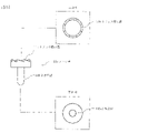
光スイッチング回転部の構成を図12A及び図12Bに示す。図12Aは光スイッチング回転部の正面図、上面図及び下面図であり、図12Bは光スイッチング回転部の斜視図である。図12A及び図12Bにおいて、200は光スイッチング回転部、201は第1の光接続体、202は第2の光接続体、203は接続回転体、206は切替対象光ファイバ、207は切替対象光ファイバ群、213は接続回転体歯車である。
図12A及び図12Bにおいて、光スイッチング回転部200は、第1の光接続体201、第2の光接続体202及び接続回転体203を有する。第1の光接続体201には、1本の切替対象光ファイバ206が固定されている。第2の光接続体202には、切替対象光ファイバ群207の複数の光ファイバが固定されている。接続回転体203は、回転運動体120の変換する回転に同期して軸を中心に回転し、一方の端面に接する第1の光接続体201に固定された1本の切替対象光ファイバ206と他方の端面に接する第2の光接続体202に固定された切替対象光ファイバ群207の中の1本の光ファイバとを切替接続する。
図12A及び図12Bにおける光スイッチング回転部200の歯の数は、図8A等の回転運動体120の歯の数と一致する必要はない。
具体的には、接続回転体203は、接続回転体歯車213及び接続光路(不図示)を有する。接続回転体歯車213は、回転運動体120の変換する回転運動に応じて、軸を中心に接続回転体203を回転させる。即ち、接続回転体歯車213は、回転子121の回転を伝える回転子歯車122によって、軸を中心に接続回転体203を回転させる。接続光路は、接続回転体203の軸に垂直な一方の端面の回転の中心と軸に垂直な他方の端面の回転の中心から所定距離を半径とする円周上にある接続点とを光で接続する。
第1の光接続体201は、接続回転体203の一方の端面に接し、1本の切替対象光ファイバ206を接続回転体203の回転の中心に対向する位置に固定する。第2の光接続体202は、接続回転体203の他方の端面に接し、切替対象光ファイバ群207の複数の光ファイバを接続回転体203の回転の中心から所定距離を半径とする円周上に固定する。接続回転体203が回転することによって、接続回転体203の接続光路が、第1の光接続体201の1本の切替対象光ファイバ206と第2の光接続体202の切替対象光ファイバ群207の中の1本の光ファイバとを切替接続する。
1本の切替対象光ファイバ206及び接続回転体203の接続光路の端点にそれぞれコリメートレンズを設け、コリメート光で接続してもよい。また、切替対象光ファイバ群207の複数の光ファイバ及び接続回転体203の接続光路の端点にそれぞれコリメートレンズを設け、コリメート光で接続してもよい。コリメート光で接続することによって、接続損失を減少させることができる。
以上説明したように、本開示の光スイッチは電力の供給を不要とすることができ、当該光スイッチを利用した光スイッチシステムは低消費電力で動作することができる。
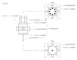
監視用回転部300の構成を図13A、図13B及び図13Cに示す。図13Aは光監視用回転部の正面図、上面図及び下面図であり、図13Bは第1の監視回転体の監視光路の接続・遮断パターン、図13Cは監視用回転部の斜視図である。図13A、図13B及び図13Cにおいて、300は監視用回転部、301は第1の監視回転体、302は第3の光接続体、303は第4の光接続体、304は監視回転体歯車、306は監視用送信光ファイバ、307は監視用受信光ファイバである。
監視用回転部300は、第1の監視回転体301が回転運動体120の回転に同期して回転し、接続回転体203の回転角度を検出する。図13A、図13B及び図13Cにおける監視用回転部300の歯の数は、図8A等の回転運動体120の歯の数と必ずしも一致する必要はない。
具体的には、監視用回転部300は、第1の監視回転体301、第3の光接続体302、第4の光接続体303及び監視回転体歯車304を有する。第1の監視回転体301は、軸に垂直な一方の端面と軸に垂直な他方の端面とを接続する複数の監視光路(不図示)を有する。第1の監視回転体301は、回転運動体120の変換する回転運動に応じて、軸を中心に回転する。回転運動は、回転子121の回転を伝える監視回転体歯車304によって伝えられる。第1の監視回転体301の回転の角度によって監視光路の接続・遮断のパターンが異なる。第3の光接続体302は、第1の監視回転体301の一方の端面に接し、監視用の光を送信する複数の監視用送信光ファイバ306を固定する。第4の光接続体303は、第1の監視回転体301の他方の端面に接し、監視用の光を受信する複数の監視用受信光ファイバ307を固定する。
監視用送信光ファイバ306及び第1の監視回転体301の監視光路の端点にそれぞれコリメートレンズを設け、コリメート光で接続してもよい。また、監視用受信光ファイバ307及び第1の監視回転体301の監視光路の端点にそれぞれコリメートレンズを設け、コリメート光で接続してもよい。コリメート光で接続することによって、接続損失を減少させることができる。
第1の監視回転体301の回転によって、複数の監視用送信光ファイバ306から複数の監視用受信光ファイバ307へのそれぞれの光の接続・遮断のパターンが固有に変化する。例えば、図13Bにおいて、第1の監視回転体301は、それぞれ、軸の回転方向に45度単位で8分割されている。45度単位の場合は、0、45、90、135、180、225、270、315度の8分割である。監視用送信光ファイバ306には3本の光ファイバを用い、3本の監視用送信光ファイバ306を第3の光接続体302の端面の0度の位置に固定する。監視用受信光ファイバ307にも同様に3本の光ファイバを用い、3本の監視用受信光ファイバ307を第4の光接続体303の端面の0度の位置に固定する。第1の監視回転体301は、3本の監視用送信光ファイバ306と3本の監視用受信光ファイバ307とのそれぞれの接続、遮断のパターンが回転角度によって固有に異なる。
第1の監視回転体301が45度単位で回転すると、3本の監視用送信光ファイバ306から3本の監視用受信光ファイバ307への接続、遮断のパターンが固有に変化する。接続を1、遮断を0とし、図13Bで黒丸を「1」、白丸を「0」とすると、角度0、45、90、135、180、225、270、315度に応じて、中心から周縁部に向けてそれぞれ、111、011、101、001、110、010、100、000の8通り(=3bit)を検出することができる。
例えば、10度単位で回転する第1の監視回転体301であれば、36通りの状態を監視するために10度ごとに36分割し、第1の監視回転体301は6個の監視光路を配置し、監視用送信光ファイバ306と監視用受信光ファイバ307も6本ずつ必要となる。検出する回転角度単位に応じて、第1の監視回転体301の監視光路の個数、監視用送信光ファイバ306及び監視用受信光ファイバ307の本数を決定すればよい。
第1の監視回転体301は、回転子121の回転に同期し、接続回転体203も回転子121の回転に同期する。従って、監視用回転部300の検出する回転角度から、接続回転体203の回転角度を知ることができ、その結果、光スイッチング回転部200が切替対象光ファイバ206と切替対象光ファイバ群207のどの光ファイバとを接続しているかを監視することができる。
以上説明したように、監視用回転部を備える本開示の光スイッチは電力の供給を不要とすることができ、当該光スイッチを利用した光スイッチシステムは低消費電力で動作することができる。
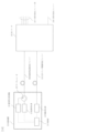
本開示の光スイッチシステムの他の構成を図14に示す。図14において、10は光スイッチ、112は光スイッチ駆動用光ファイバ、20は制御装置、21は制御部、22は駆動用光源、23は監視用光源、24は監視用光受信機、25はサーキュレータ、206は切替対象光ファイバ、207は切替対象光ファイバ群、308は監視用送受信光ファイバである。
光スイッチシステムは、光スイッチ10及び制御装置20を備える。制御装置20は、制御部21及び駆動用光源22、監視用光源23監視用光受信機24及びサーキュレータ25を有する。図1の光スイッチシステムとの違いは、制御装置20がサーキュレータ25をさらに有し、光スイッチ10の監視用に監視用送受信光ファイバ308を用いている点である。
制御部21は、監視用光源23に監視用の光を送信させる。監視用光源23はサーキュレータ25及び監視用送受信光ファイバ308を通して、光スイッチ10に監視用の光を供給する。監視用光受信機24は監視用送受信光ファイバ308及びサーキュレータ25を経由し、光スイッチ10から監視用の光を受信する。制御部21は、監視用光受信機24からの受信信号を受信し、光スイッチ10が指示通りに動作しているかを監視する。
本開示の光スイッチの他の構成を図15に示す。図15において、10は光スイッチ、100は光駆動回転部、110は光膨張体、112は光スイッチ駆動用光ファイバ、115はノック棒、120は回転運動体、200は光スイッチング回転部、203は接続回転体、206は切替対象光ファイバ、207は切替対象光ファイバ群、300は監視用回転部、311は第2の監視回転体、308は監視用送受信光ファイバである。光駆動回転部100と光スイッチング回転部は図2の光スイッチと同じ構成である。図2の光スイッチとは監視用回転部300の構成が異なる。なお、図15では、光駆動回転部100の点線内だけ、筐体140の内部を透視した図面としている。
光スイッチの監視用回転部300では、光駆動回転部100の中にある部品が一定角度だけ回転すると、その回転が監視用回転部300へ伝わり、監視用回転部300の第2の監視回転体311が一定角度回転する。監視用送受信光ファイバ308から監視用回転部300へ光が入射され、その光がどのように反射・遮断されて監視用送受信光ファイバ308へ再入射されるかにより光スイッチング回転部200の中の接続回転体203の回転角度を検出することができる。従って、制御装置20は、光スイッチ10が、切替対象光ファイバ206と切替対象光ファイバ群207の中のどの光ファイバとを指示通りに接続・遮断しているかを監視することができる。
監視用回転部300の構成を図16A、図16B及び図16Cに示す。図16Aは光監視用回転部の正面図、上面図及び下面図であり、図16Bは第2の監視回転体の反射・遮断のパターン、図16Cは監視用回転部の斜視図である。図16A、図16B及び図16Cにおいて、300は監視用回転部、311は第2の監視回転体、313は第5の光接続体、304は監視回転体歯車、308は監視用送受信光ファイバである。
監視用回転部300は、回転運動体120の回転に同期して回転し、回転運動体120の回転角度を検出する。図16A、図16B及び図16Cにおける監視用回転部300の歯の数は、図8A等の回転運動体120の歯の数と一致する必要はない。
監視用回転部300は、第2の監視回転体311が回転運動体120の回転に同期して回転し、接続回転体203の回転角度を検出する。
具体的には、監視用回転部300は、第2の監視回転体311、第5の光接続体313及び監視回転体歯車304を有する。第2の監視回転体311は、軸に垂直な一方の端面に複数の反射・遮断部(不図示)を持つ反射板を有する。第2の監視回転体311は、回転運動体120の変換する回転運動に応じて、軸を中心に回転する。回転運動は、回転子121の回転を伝える監視回転体歯車304によって伝えられる。第2の監視回転体311の回転の角度によって反射・遮断のパターンが異なる。第5の光接続体313は、第2の監視回転体311の一方の端面に接し、監視用の光を送受信する複数の監視用送受信光ファイバ308を固定する。
監視用送受信光ファイバ308の端点にコリメートレンズを設け、コリメート光を反射・遮断してもよい。コリメート光で接続することによって、接続損失を減少させることができる。
第2の監視回転体311の回転によって、複数の監視用送受信光ファイバ308からの光の反射・遮断のパターンが固有に変化する。例えば、図16Bにおいて、第2の監視回転体311は、それぞれ、軸の回転方向に45度単位で8分割されている。45度単位の場合は、0、45、90、135、180、225、270、315度の8分割である。監視用送受信光ファイバ308には3本の光ファイバを用い、3本の監視用送受信光ファイバ308を第5の光接続体313の端面の0度の位置に固定する。第2の監視回転体311は、3本の監視用送受信光ファイバ308に対してそれぞれの反射、遮断のパターンが回転角度によって固有に異なる。
第2の監視回転体311が45度単位で回転すると、3本の監視用送受信光ファイバ308に対して反射、遮断のパターンが固有に変化する。反射を1、遮断を0とし、図16Bで黒丸を「1」、白丸を「0」とすると、角度0、45、90、135、180、225、270、315度に応じて、中心から周縁部に向けてそれぞれ、111、011、101、001、110、010、100、000の8通り(=3bit)を検出することができる。
3本の監視用送受信光ファイバ308に対して反射とする場合は、第2の監視回転体311で監視用送受信光ファイバ308からの監視用の光をミラーで反射して、監視用の光を監視用送受信光ファイバ308に戻すようにすればよい。3本の監視用送受信光ファイバ308に対して遮断とする場合は、第2の監視回転体311で監視用送受信光ファイバ308からの監視用の光を無反射としたり、吸収したり、監視用送受信光ファイバ308とは別方向への反射としたりして、監視用の光を監視用送受信光ファイバ308に戻さないようにすればよい。
検出する回転角度単位に応じて、第2の監視回転体311の反射・遮断の個数及び監視用送受信光ファイバ308の本数を決定する点は、図13Bと同じである。
第2の監視回転体311は、回転子121の回転に同期し、接続回転体203も回転子121の回転に同期する。従って、監視用回転部300の検出する回転角度から、接続回転体203の回転角度を知ることができ、その結果、光スイッチング回転部200が切替対象光ファイバ206と切替対象光ファイバ群207のどの光ファイバとを接続しているかを監視することができる。
以上説明したように、監視用回転部を備える本開示の光スイッチは電力の供給を不要とすることができ、当該光スイッチを利用した光スイッチシステムは低消費電力で動作することができる。
本開示は通信産業に適用することができる。
10:光スイッチ
20:制御装置
21:制御部
22:駆動用光源
23:監視用光源
24:監視用光受信機
25:サーキュレータ
100:光駆動回転部
110:光膨張体
110-1:光膨張部材
111:テコ
112:光スイッチ駆動用光ファイバ
115:ノック棒
115-1:ノック棒の溝
115-2:押圧部
120:回転運動体
121:回転子
122:回転子歯車
123:羽
124:カム
124-1:カムの溝
124-2:カムのノック孔
125:凸部
126:弾性体
127:軸孔
140:筐体
141:回転子孔
142:凹部
143:筐体のノック孔
200:光スイッチング回転部
201:第1の光接続体
202:第2の光接続体
203:接続回転体
206:切替対象光ファイバ
207:切替対象光ファイバ群
213:接続回転体歯車
300:監視用回転部
301:第1の監視回転体
302:第3の光接続体
303:第4の光接続体
304:監視回転体歯車
306:監視用送信光ファイバ
307:監視用受信光ファイバ
308:監視用送受信光ファイバ
311:第2の監視回転体
313:第5の光接続体
20:制御装置
21:制御部
22:駆動用光源
23:監視用光源
24:監視用光受信機
25:サーキュレータ
100:光駆動回転部
110:光膨張体
110-1:光膨張部材
111:テコ
112:光スイッチ駆動用光ファイバ
115:ノック棒
115-1:ノック棒の溝
115-2:押圧部
120:回転運動体
121:回転子
122:回転子歯車
123:羽
124:カム
124-1:カムの溝
124-2:カムのノック孔
125:凸部
126:弾性体
127:軸孔
140:筐体
141:回転子孔
142:凹部
143:筐体のノック孔
200:光スイッチング回転部
201:第1の光接続体
202:第2の光接続体
203:接続回転体
206:切替対象光ファイバ
207:切替対象光ファイバ群
213:接続回転体歯車
300:監視用回転部
301:第1の監視回転体
302:第3の光接続体
303:第4の光接続体
304:監視回転体歯車
306:監視用送信光ファイバ
307:監視用受信光ファイバ
308:監視用送受信光ファイバ
311:第2の監視回転体
313:第5の光接続体
Claims (8)
- 光の照射によって膨張し、光の遮断によって縮小する光膨張体、
前記光膨張体の膨張・縮小を一定距離だけ往復する直線運動に変換するノック棒、
及び前記ノック棒の一定距離だけ往復する直線運動に応じて一定の角度だけ回転する回転運動に変換する回転運動体
を有する光駆動回転部と、
1本の切替対象光ファイバが固定された第1の光接続体、
切替対象光ファイバ群の光ファイバがそれぞれ固定された第2の光接続体、
及び前記回転運動体の変換する回転に同期して軸を中心に回転し、一方の端面に接する前記第1の光接続体に固定された1本の切替対象光ファイバと他方の端面に接する前記第2の光接続体に固定された切替対象光ファイバ群の中の1本の光ファイバとを切替接続する接続回転体
を有する光スイッチング回転部と、
を備える光スイッチ。 - 前記回転運動体は、
筐体の内部で軸を中心に回転する回転子、
前記回転子の側面に固定され、前記回転子の回転を伝える回転子歯車、
前記回転子の前記ノック棒の側の端面に固定され、前記ノック棒の側の先端が平坦な斜面となっている羽、
前記筐体の内部に固定され、円筒状の前記羽の側の端面に円環状に設けられた鋸歯状の溝の斜面であって前記羽の斜面と同じ方向の傾きを持つ斜面で前記羽の斜面を受け止める円筒状のカム、
及び前記筐体に固定され、前記回転子を前記カムに向かって押し返す弾性体
を有し、
前記ノック棒は、前記カムの円筒状内部を往復し、前記カムの鋸歯状の溝と同じ周期で半ピッチずれた鋸歯状の溝であって、斜面が前記羽の斜面と同じ方向の傾きの斜面を持つ溝を前記羽の側の端面に円環状に有し、
前記光膨張体が縮小している際は、前記羽の斜面が前記弾性体によって前記カムの鋸歯状の溝の斜面に押し当てられ、
前記光膨張体が膨張する際は、前記ノック棒が前記回転子に向かって前進して、前記ノック棒の鋸歯状の溝の斜面が前記羽の斜面に押し当てられ、押し当てられた前記羽の斜面が前記ノック棒の鋸歯状の歯の斜面を滑ることによって、前記回転子が回転し、
前記光膨張体が膨張から縮小に転じる際は、前記ノック棒が前記回転子から後退し、前記弾性体によって押し返された前記回転子が前記カムに向かい、前記羽の斜面が前記カムの鋸歯状の溝の斜面に押し当てられ、押し当てられた前記羽の斜面が前記カムの鋸歯状の歯の斜面を滑ることによって、前記回転子が回転する
ことを特徴とする請求項1に記載の光スイッチ。 - 前記光膨張体は、黒色の材料又は内部に気泡を含む材料で構成されていることを特徴とする請求項1又は2に記載の光スイッチ。
- 前記接続回転体は、
前記回転運動体の変換する回転運動に応じて、軸を中心に回転させる接続回転体歯車、
及び軸に垂直な一方の端面の回転の中心と軸に垂直な他方の端面の回転の中心から所定距離を半径とする円周上に配置された接続点とを接続する接続光路
を有し、
前記第1の光接続体は、前記接続回転体の一方の端面に接し、前記1本の切替対象光ファイバを前記接続回転体の回転の中心に対向する位置に固定し、
前記第2の光接続体は、前記接続回転体の他方の端面に接し、前記切替対象光ファイバ群の光ファイバを前記接続回転体の回転の中心から所定距離を半径とする円周上にそれぞれ固定し、
前記接続回転体が回転することによって、前記接続光路が前記第1の光接続体の前記1本の切替対象光ファイバと前記第2の光接続体の前記切替対象光ファイバ群の中の1本の光ファイバとを切替接続する
ことを特徴とする請求項1から3のいずれかに記載の光スイッチ。 - 前記回転運動体の回転に同期して回転し、前記接続回転体の回転角度を検出する監視用回転部をさらに備えることを特徴とする請求項1から4のいずれかに記載の光スイッチ。
- 前記監視用回転部は、
前記回転運動体の変換する回転運動に応じて、軸を中心に回転し、軸に垂直な一方の端面と軸に垂直な他方の端面とを接続する複数の監視光路であって、回転の角度によって接続・遮断のパターンが異なる監視光路を有する第1の監視回転体と、
前記第1の監視回転体の一方の端面に接し、監視用の光を送信する複数の監視用送信光ファイバを固定する第3の光接続体と、
前記第1の監視回転体の他方の端面に接し、監視用の光を受信する複数の監視用受信光ファイバを固定する第4の光接続体と、を有し、
前記第1の監視回転体の回転によって、前記複数の監視用送信光ファイバから前記複数の監視用受信光ファイバへのそれぞれの光の接続・遮断のパターンが固有に変化することを特徴とする請求項5に記載の光スイッチ。 - 前記監視用回転部は、
前記回転運動体の変換する回転運動に応じて、軸を中心に回転し、軸に垂直な一方の端面に回転の角度によって反射・遮断のパターンが異なる反射板を有する第2の監視回転体と、
前記第2の監視回転体の一方の端面に接し、監視用の光を送受信する複数の監視用送受信光ファイバを固定する第5の光接続体と、を有し、
前記第2の監視回転体の回転によって、前記複数の監視用送受信光ファイバでのそれぞれの光の反射・無反射のパターンが固有に変化することを特徴とする請求項5に記載の光スイッチ。 - 請求項1から7のいずれかに記載の光スイッチと、
前記光膨張体に膨張を起こさせる光を供給する駆動用光源及び前記駆動用光源に照射、遮断を指示する制御部を有する制御装置と、
を備えることを特徴とする光スイッチシステム。
Priority Applications (3)
| Application Number | Priority Date | Filing Date | Title |
|---|---|---|---|
| PCT/JP2021/029430 WO2023013071A1 (ja) | 2021-08-06 | 2021-08-06 | 光スイッチ及び光スイッチシステム |
| US18/291,569 US20240264381A1 (en) | 2021-08-06 | 2021-08-06 | Optical switch and optical switch system |
| JP2023539582A JP7540601B2 (ja) | 2021-08-06 | 2021-08-06 | 光スイッチ及び光スイッチシステム |
Applications Claiming Priority (1)
| Application Number | Priority Date | Filing Date | Title |
|---|---|---|---|
| PCT/JP2021/029430 WO2023013071A1 (ja) | 2021-08-06 | 2021-08-06 | 光スイッチ及び光スイッチシステム |
Publications (1)
| Publication Number | Publication Date |
|---|---|
| WO2023013071A1 true WO2023013071A1 (ja) | 2023-02-09 |
Family
ID=85155495
Family Applications (1)
| Application Number | Title | Priority Date | Filing Date |
|---|---|---|---|
| PCT/JP2021/029430 Ceased WO2023013071A1 (ja) | 2021-08-06 | 2021-08-06 | 光スイッチ及び光スイッチシステム |
Country Status (3)
| Country | Link |
|---|---|
| US (1) | US20240264381A1 (ja) |
| JP (1) | JP7540601B2 (ja) |
| WO (1) | WO2023013071A1 (ja) |
Citations (5)
| Publication number | Priority date | Publication date | Assignee | Title |
|---|---|---|---|---|
| JPH07287178A (ja) * | 1994-02-25 | 1995-10-31 | Perkin Elmer Corp:The | 光学的切り換え装置 |
| JP2000330042A (ja) * | 1999-05-18 | 2000-11-30 | Shuukou Denki Kk | 光路切替装置 |
| JP2003015061A (ja) * | 2001-07-04 | 2003-01-15 | Hitachi Metals Ltd | 光スイッチ |
| JP2006187060A (ja) * | 2004-12-27 | 2006-07-13 | Nikon Corp | マイクロアクチュエータ及びその製造方法、並びに、光学装置及び光スイッチ |
| JP2008033155A (ja) * | 2006-07-31 | 2008-02-14 | Canon Inc | 撮像装置 |
-
2021
- 2021-08-06 WO PCT/JP2021/029430 patent/WO2023013071A1/ja not_active Ceased
- 2021-08-06 US US18/291,569 patent/US20240264381A1/en active Pending
- 2021-08-06 JP JP2023539582A patent/JP7540601B2/ja active Active
Patent Citations (5)
| Publication number | Priority date | Publication date | Assignee | Title |
|---|---|---|---|---|
| JPH07287178A (ja) * | 1994-02-25 | 1995-10-31 | Perkin Elmer Corp:The | 光学的切り換え装置 |
| JP2000330042A (ja) * | 1999-05-18 | 2000-11-30 | Shuukou Denki Kk | 光路切替装置 |
| JP2003015061A (ja) * | 2001-07-04 | 2003-01-15 | Hitachi Metals Ltd | 光スイッチ |
| JP2006187060A (ja) * | 2004-12-27 | 2006-07-13 | Nikon Corp | マイクロアクチュエータ及びその製造方法、並びに、光学装置及び光スイッチ |
| JP2008033155A (ja) * | 2006-07-31 | 2008-02-14 | Canon Inc | 撮像装置 |
Also Published As
| Publication number | Publication date |
|---|---|
| US20240264381A1 (en) | 2024-08-08 |
| JP7540601B2 (ja) | 2024-08-27 |
| JPWO2023013071A1 (ja) | 2023-02-09 |
Similar Documents
| Publication | Publication Date | Title |
|---|---|---|
| US4239330A (en) | Multiple optical switch | |
| CN102244358B (zh) | 一种外腔式可调谐激光器 | |
| US6597829B2 (en) | 1xN optical fiber switch | |
| JP5675901B2 (ja) | 光ファイバーロータリージョイントおよび光信号の伝送方法 | |
| US7734130B2 (en) | Polarization-maintaining optical rotary coupling | |
| CN111158139A (zh) | 一种用于实时太赫兹医学成像的超高速旋转棱镜光纤延迟线 | |
| JP7540601B2 (ja) | 光スイッチ及び光スイッチシステム | |
| WO2023062677A1 (ja) | 光スイッチ及び光スイッチシステム | |
| CN110824698A (zh) | 光学模组和激光模块 | |
| CN218728349U (zh) | 激光光闸 | |
| US6111997A (en) | Tunable filtering device for optical communications | |
| US5684632A (en) | Variable wavelength optical filter | |
| US5823906A (en) | Nutation motion generator | |
| CN211426929U (zh) | 光学模组和激光模块 | |
| CN110361826B (zh) | 记忆合金驱动主备份结构的轴系间高速率信息传输装置 | |
| WO2022168205A1 (ja) | 光スイッチ | |
| WO2012112412A2 (en) | Fiber optic system with parabolic mirror collimator | |
| JP7524952B2 (ja) | 光スイッチ | |
| CN214097869U (zh) | 一种自由空间式的机械光开关装置 | |
| US6407867B1 (en) | Multiple beam spacer with a beam splitter cube and two roof mirrors | |
| CN119805670B (zh) | 一种空间离轴双通道光纤旋转连接器 | |
| CN218513854U (zh) | 激光光闸 | |
| US20020001429A1 (en) | Optical switch | |
| CN219328938U (zh) | 空间干涉仪和量子通信设备 | |
| CN212704992U (zh) | 激光剥离转移系统 |
Legal Events
| Date | Code | Title | Description |
|---|---|---|---|
| 121 | Ep: the epo has been informed by wipo that ep was designated in this application |
Ref document number: 21952894 Country of ref document: EP Kind code of ref document: A1 |
|
| WWE | Wipo information: entry into national phase |
Ref document number: 2023539582 Country of ref document: JP |
|
| NENP | Non-entry into the national phase |
Ref country code: DE |
|
| 122 | Ep: pct application non-entry in european phase |
Ref document number: 21952894 Country of ref document: EP Kind code of ref document: A1 |