WO2023008456A1 - Transfer apparatus - Google Patents
Transfer apparatus Download PDFInfo
- Publication number
- WO2023008456A1 WO2023008456A1 PCT/JP2022/028859 JP2022028859W WO2023008456A1 WO 2023008456 A1 WO2023008456 A1 WO 2023008456A1 JP 2022028859 W JP2022028859 W JP 2022028859W WO 2023008456 A1 WO2023008456 A1 WO 2023008456A1
- Authority
- WO
- WIPO (PCT)
- Prior art keywords
- transfer
- gap
- web
- sheet
- varnish
- Prior art date
Links
- 238000012546 transfer Methods 0.000 title claims abstract description 147
- 230000007246 mechanism Effects 0.000 claims abstract description 57
- 239000000463 material Substances 0.000 claims abstract description 53
- 230000007723 transport mechanism Effects 0.000 claims description 4
- 238000003825 pressing Methods 0.000 claims description 3
- 239000011888 foil Substances 0.000 description 176
- 239000002966 varnish Substances 0.000 description 147
- 238000001723 curing Methods 0.000 description 59
- 239000010410 layer Substances 0.000 description 41
- 238000012545 processing Methods 0.000 description 35
- 238000004804 winding Methods 0.000 description 24
- 238000010586 diagram Methods 0.000 description 14
- 238000001514 detection method Methods 0.000 description 12
- 230000002093 peripheral effect Effects 0.000 description 10
- 238000000576 coating method Methods 0.000 description 8
- 238000011144 upstream manufacturing Methods 0.000 description 8
- 230000000694 effects Effects 0.000 description 7
- 230000004048 modification Effects 0.000 description 7
- 238000012986 modification Methods 0.000 description 7
- 239000002344 surface layer Substances 0.000 description 7
- 239000011248 coating agent Substances 0.000 description 6
- 238000003851 corona treatment Methods 0.000 description 5
- 238000000034 method Methods 0.000 description 5
- 239000000126 substance Substances 0.000 description 5
- 238000007726 management method Methods 0.000 description 4
- 239000002184 metal Substances 0.000 description 4
- 230000008569 process Effects 0.000 description 4
- 230000007480 spreading Effects 0.000 description 4
- 238000003892 spreading Methods 0.000 description 4
- 239000011247 coating layer Substances 0.000 description 3
- 230000001678 irradiating effect Effects 0.000 description 3
- 238000003475 lamination Methods 0.000 description 3
- CBENFWSGALASAD-UHFFFAOYSA-N Ozone Chemical compound [O-][O+]=O CBENFWSGALASAD-UHFFFAOYSA-N 0.000 description 2
- 230000000740 bleeding effect Effects 0.000 description 2
- 238000007599 discharging Methods 0.000 description 2
- 238000012423 maintenance Methods 0.000 description 2
- 238000012805 post-processing Methods 0.000 description 2
- 238000004080 punching Methods 0.000 description 2
- 230000001960 triggered effect Effects 0.000 description 2
- 239000002759 woven fabric Substances 0.000 description 2
- 230000037303 wrinkles Effects 0.000 description 2
- 240000006829 Ficus sundaica Species 0.000 description 1
- 238000003848 UV Light-Curing Methods 0.000 description 1
- 230000002159 abnormal effect Effects 0.000 description 1
- 239000012790 adhesive layer Substances 0.000 description 1
- QVGXLLKOCUKJST-UHFFFAOYSA-N atomic oxygen Chemical compound [O] QVGXLLKOCUKJST-UHFFFAOYSA-N 0.000 description 1
- 238000005452 bending Methods 0.000 description 1
- 230000005540 biological transmission Effects 0.000 description 1
- 230000008859 change Effects 0.000 description 1
- 238000004040 coloring Methods 0.000 description 1
- 239000000470 constituent Substances 0.000 description 1
- 238000012937 correction Methods 0.000 description 1
- 238000005520 cutting process Methods 0.000 description 1
- 230000007547 defect Effects 0.000 description 1
- 238000000151 deposition Methods 0.000 description 1
- 238000002845 discoloration Methods 0.000 description 1
- 230000001747 exhibiting effect Effects 0.000 description 1
- 239000004744 fabric Substances 0.000 description 1
- 238000010191 image analysis Methods 0.000 description 1
- 230000006872 improvement Effects 0.000 description 1
- 230000010365 information processing Effects 0.000 description 1
- 230000005764 inhibitory process Effects 0.000 description 1
- 238000007689 inspection Methods 0.000 description 1
- 238000010030 laminating Methods 0.000 description 1
- 238000002844 melting Methods 0.000 description 1
- 230000008018 melting Effects 0.000 description 1
- 229910052760 oxygen Inorganic materials 0.000 description 1
- 239000001301 oxygen Substances 0.000 description 1
- 239000000123 paper Substances 0.000 description 1
- 238000011160 research Methods 0.000 description 1
- 239000011347 resin Substances 0.000 description 1
- 229920005989 resin Polymers 0.000 description 1
- 230000004043 responsiveness Effects 0.000 description 1
- 238000001179 sorption measurement Methods 0.000 description 1
- 239000000758 substrate Substances 0.000 description 1
- 230000007704 transition Effects 0.000 description 1
- 238000009281 ultraviolet germicidal irradiation Methods 0.000 description 1
Images


Classifications
-
- B—PERFORMING OPERATIONS; TRANSPORTING
- B65—CONVEYING; PACKING; STORING; HANDLING THIN OR FILAMENTARY MATERIAL
- B65C—LABELLING OR TAGGING MACHINES, APPARATUS, OR PROCESSES
- B65C1/00—Labelling flat essentially-rigid surfaces
- B65C1/02—Affixing labels to one flat surface of articles, e.g. of packages, of flat bands
-
- B—PERFORMING OPERATIONS; TRANSPORTING
- B65—CONVEYING; PACKING; STORING; HANDLING THIN OR FILAMENTARY MATERIAL
- B65C—LABELLING OR TAGGING MACHINES, APPARATUS, OR PROCESSES
- B65C9/00—Details of labelling machines or apparatus
- B65C9/40—Controls; Safety devices
- B65C9/42—Label feed control
Definitions
- the present invention relates to a transfer device.
- a transfer device that transfers a transfer material such as foil from a transfer web conveyed by roll-to-roll to a transferred material such as a sheet.
- a curable coating layer applied to the surface of the material to be transferred and the transfer web are brought into close contact with each other, and the surface shape formed by the irregularities on the surface of the transfer web is transferred to the coating layer, which is called a lamination coating process.
- a transfer device that transfers the surface shape of a transfer web to a material to be transferred.
- the transfer section gap which is the gap between the web path of the transfer web in the transfer section and the conveying surface of the material to be transferred, in order to increase the commercial value of the transfer device.
- the present invention has been made in such a situation, and one of the exemplary purposes of certain aspects thereof is to provide a transfer device with enhanced commercial value through appropriate management of the transfer interval gap.
- a transfer device transfers a transfer material or a transfer material from a transfer web conveyed along a web path to a transfer material conveyed along a conveying surface in a transfer section.
- a transfer device for transferring the surface shape of a transfer web comprising: a gap adjustment mechanism for adjusting the size of a gap between a conveying surface and a web path in a transfer section; and a control device that adjusts the size according to the thickness of the transferred material.
- This apparatus includes a web transport mechanism for transporting a transfer web along a web path, a transfer target transport mechanism for transporting a transfer target, and a transfer material of the transfer web or the surface shape of the transfer web being transferred to the transfer target.
- An ultraviolet light source unit that irradiates ultraviolet light from an irradiation position on the opposite side of the conveying surface of the transferred material conveying mechanism with respect to the web path in the transfer section where the transfer section is moved up and down the web path in the transfer section.
- a gap adjusting mechanism for adjusting the gap between the web path and the conveying surface. The UV light source unit moves up and down with the web path when the gap size exceeds a threshold value.
- a transfer device with enhanced commercial value can be provided.
- FIG. 1 is a diagram schematically showing a printing system according to an embodiment
- FIG. 1 is a diagram schematically showing a printing system according to an embodiment
- FIG. FIG. 4 shows a semi-cured varnish layer
- Figure 2 shows the foil stamping apparatus of Figure 1
- Figure 2 shows the foil stamping apparatus of Figure 1
- 2 is an enlarged view showing the periphery of a foil stamping section of the foil stamping apparatus of FIG. 1
- FIG. FIG. 5 is a diagram showing the clearance adjustment mechanism of FIG. 4 and its surroundings
- FIG. 5 is a diagram showing the clearance adjustment mechanism of FIG. 4 and its surroundings
- FIG. 5 is a diagram showing the clearance adjustment mechanism of FIG. 4 and its surroundings
- FIG. 5 is a diagram showing the clearance adjustment mechanism of FIG. 4 and its surroundings
- FIGS. 12(a) to 12(c) are diagrams showing the operation of the foil stamping apparatus in chronological order when web loading/exchange work is performed.
- the gap between the transfer web and the conveying surface of the material to be transferred in the transfer section must, of course, be large enough for the material to be transferred to enter. If the contact pressure between the web and the material to be transferred is too low, and if the gap is too small, the contact pressure between the transfer web and the material to be transferred is too high, and poor contact may occur in either case. As a result, transfer failure or transport failure may occur.
- the size of the transfer section gap which is the gap between the web path of the transfer web in the transfer section and the conveying surface of the material to be transferred, is adjusted to the size corresponding to the thickness of the material to be transferred. adjust. This makes it possible to achieve good transfer.
- the ultraviolet light source unit transfers to the transfer web in the transfer section. It is necessary to irradiate the varnish with ultraviolet rays to cure it.
- the UV light source unit irradiates UV light from a relatively close distance to the transfer web, ie, a distance where the necessary amount of UV light for curing can reach. If the ultraviolet light source unit is in this position, for example, when attaching or replacing the transfer web, the transfer web must be passed through a small gap between the ultraviolet light source unit and the conveying surface of the material to be transferred, making the work difficult. In addition, for example, it is difficult to access a small gap between the ultraviolet light source unit and the transport surface of the transferred material for repairing a faulty part or maintenance inspection. In other words, it is difficult to maintain.
- the transfer device of the present invention can raise the ultraviolet light source unit in addition to the web path of the transfer web in the transfer section. This makes it easier to install/replace the web and perform maintenance.
- the transfer device is a foil stamping device, i.e., a device that transfers foil to a transferred object
- the transfer device may be a device that transfers to
- the transfer device may be a device that performs a so-called lamination coating process in which a hardenable coating layer and a transfer web are brought into close contact with each other to transfer the surface shape of the transfer web to the material to be transferred.
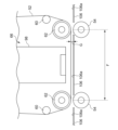
- FIGS. 1 and 2 are diagrams schematically showing a printing system 10 in which a foil stamping device 16 according to an embodiment is used.
- 1 is a side view
- FIG. 2 is a plan view.
- the printing system 10 is a device that applies predetermined printing to a sheet while conveying the sheet. Sheets are made of various materials such as paper, cloth, resin, and metal.
- the direction in which the sheet is conveyed (the direction from right to left in FIGS. 1 and 2) is the conveying direction Y
- the direction perpendicular to the conveying direction Y (the direction perpendicular to the paper surface in FIG. 1 and the vertical direction in FIG. 2). ) is called the width direction X.
- the right side in the width direction X as viewed from the upstream side in the transport direction Y is called the right side in the width direction X
- the left side is called the left side in the width direction X
- the edge on the downstream side in the transport direction Y is called the leading edge of the sheet
- the edge on the upstream side is called the trailing edge of the sheet.
- the printing system 10 includes a sheet feeding device 12 that feeds sheets one by one, a varnish applying device 14 that applies varnish to the sheets that are fed one by one, and a varnish on the sheet using the tackiness of varnish.
- a foil stamping device 16 that performs foil stamping by transferring foil to a sheet; a stacker 18 that accumulates sheets;
- the paper feeding device 12, the varnish coating device 14, the foil stamping device 16, and the stacker 18 are arranged in a row in this order from the upstream side (the right side in FIGS. 1 and 2) in the transport direction Y.
- the control device 20 is connected to the paper feeding device 12 , the varnish coating device 14 , the foil stamping device 16 and the stacker 18 via the network 2 .
- the paper feeding device 12 includes a feeder 22 , a corona treatment section 26 and a registration section 24 .
- Feeder 22 includes table 28 and suction head 30 . Sheets are stacked on the table 28 .
- the table 28 is configured to be movable up and down.
- the suction head 30 sends out the sheets stacked on the table 28 one by one in order from the top.
- the resist section 24 includes a resist reference guide 32 provided on one end side in the width direction X (the right side in the width direction X in the illustrated example).
- the registration reference guide 32 has a guide surface 32a that is perpendicular to the width direction X and extends in the transport direction Y. As shown in FIG.
- the registration unit 24 aligns the positions of the sheets in the width direction X by abutting the sheets fed by the feeder 22 against the guide surface 32a.
- the corona treatment unit 26 includes an electrode 36 arranged above the conveying path 34 and a dielectric roller 38 arranged below the conveying path 34 so as to face the electrode 36 vertically.
- the corona treatment unit 26 modifies the surface of the sheet fed from the feeder 22 by corona discharge between the electrode 36 and the dielectric roller 38 . If the sheet is conveyed while being attracted to the conveying path 34 by the air suction unit 40, the distance between the electrode 36 and the sheet becomes constant and the corona discharge is stabilized.
- the air suction unit 40 generates a negative pressure by arranging one of the suction ports of an exhaust blower (not shown), but it may be configured to generate a negative pressure by arranging a suction fan.
- Dielectric roller 38 may be rotatable or fixed with respect to the housing of corona treatment station 26 . Furthermore, the shape is not limited to a roller shape as long as it causes corona discharge between itself and the electrode 36 .
- the corona treatment section 26 may be arranged upstream of the resist section 24 .
- the varnish application device 14 includes a sheet sensor 42 , a pair of CCD sensors 44 , at least one varnish discharger 46 , a semi-curing UV lamp 48 , and a full-curing UV lamp 50 .
- a pair of CCD sensors 44, a varnish discharger 46, a semi-curing ultraviolet lamp 48, and a full-curing ultraviolet lamp 50 are arranged in this order from the upstream side.
- the CCD sensor 44 may be a CMOS sensor.
- the varnishing device 14 includes three varnish dispensing units 46, but is not limited to this, and the varnishing device 14 extends over at least the entire area in the width direction X where printing is required.
- One varnish dispenser 46 may be included, or two or four or more varnish dispensers 46 may be included.
- the semi-curing UV lamp 48 and the main curing UV lamp 50 are LEDs that emit UV rays, but other light sources such as light bulbs and fluorescent lamps may be used as long as they emit UV rays. It is desirable that the light source has an adjustable
- the sheet sensor 42 detects sheets fed from the sheet feeding device 12 .
- the varnish ejection unit 46 is a line-type inkjet head, although not particularly limited.
- the varnish discharger 46 is triggered by the detection of the leading edge of the sheet by the sheet sensor 42, and discharges ultraviolet curable varnish according to the varnish discharge data to apply the ultraviolet curable varnish to the sheet.
- the varnish discharge data is data indicating where on the sheet the varnish is to be applied.
- a base image and a plurality of registration marks that serve as references for specifying the position of the base image may be printed in advance on the sheet fed by the paper feeding device 12 .
- the varnish applicator 14 applies varnish so as to have a predetermined relationship with the base image according to varnish discharge data that defines the varnish applied portion of the sheet.
- the base image of the sheet may be misaligned or distorted. Therefore, when applying varnish so as to have a predetermined relationship with the background image, it is necessary to correct the varnish ejection data in consideration of deviation and distortion.
- the CCD sensor 44 captures an image of the sheet triggered by the detection of the sheet by the sheet sensor 42
- the control device 20 analyzes the image data captured by the CCD sensor 44, and the difference from the theoretical positions of the plurality of registration marks results in:
- the varnish ejection data in the area surrounded by the registration marks may be corrected. Note that the method described in Japanese Patent Laid-Open No. 2016-083898 previously filed by the present applicant can be applied to this correction.
- the semi-curing ultraviolet lamp 48 irradiates the varnish on the sheet with ultraviolet rays whose output is relatively suppressed, thereby semi-curing the varnish.
- Semi-curing refers to lightly curing the varnish to such an extent that the fluidity of the varnish is reduced but the varnish is not completely cured (for example, to a state in which further curing is possible).
- the semi-cured varnish is fully cured in the foil stamping device 16 .
- the UV semi-curing lamp 48 is normally turned off or minimized.
- the semi-curing ultraviolet lamp 48 may be used even when foil stamping is not performed. For example, if the varnish applied to the sheet tends to bleed, turning on the semi-curing ultraviolet lamp 48 to semi-cure the varnish has the effect of suppressing bleed.
- the final curing ultraviolet lamp 50 irradiates the varnish applied to the sheet with ultraviolet rays to fully cure the varnish.
- the main curing UV lamp 50 is turned off.
- it has an exhaust port for exhausting the air around the UV lamp 50 for main curing.
- a fan is provided at the exhaust port to generate an exhaust flow.
- An ozone adsorption filter for adsorbing ozone generated by ultraviolet irradiation is provided upstream of the fan in the exhaust direction with a gap from the fan.
- the varnish is semi-cured by the semi-curing UV lamp 48 and the semi-cured varnish is fully cured by the foil stamping UV lamp 66 of the foil stamping device 16 .
- the main curing ultraviolet lamp 50 is turned off.
- the semi-curing ultraviolet lamp 48 and the foil stamping ultraviolet lamp 66 of the foil stamping device 16 are turned off.
- the semi-curing ultraviolet lamp 48 may not be completely turned off, and the output may be minimized.
- the semi-curing ultraviolet lamp 48 may be turned on even when foil stamping is not performed.
- an LED for irradiating ultraviolet rays is used as the light source of the ultraviolet lamp 66 for foil stamping, other light sources may be used as long as they irradiate ultraviolet rays.
- FIG. 3 is a diagram showing the varnish layers 100 and 102 applied on the sheet S by the varnish discharger 46 and semi-cured by the semi-curing ultraviolet lamp 48.
- FIG. Cured portions 100a and 102a are cured, and uncured portions 100b and 102b are not sufficiently cured.
- the cured portions 100a, 102a occupy the interior of the varnish layers 100, 102, respectively, and the uncured portions 100b, 102b occupy the surface layers of the varnish layers 100, 102, respectively. This is because the surface layer exposed to the outside air is less likely to harden due to the influence of oxygen inhibition.
- FIGS. 3(a) and 3(b) show semi-cured states formed by suppressing the output of ultraviolet rays to such an extent that the varnish layers 100 and 102 are not completely cured. Since the output of the semi-curing ultraviolet lamp 48 is relatively stronger than in the case of b), the varnish layer 100 is cured closer to the surface layer than the varnish layer 102 is. Therefore, the varnish layer 100 is more stable in shape than the varnish layer 102, and although the surface layer does not flow, it is not completely hardened and has tackiness. On the other hand, the varnish layer 102 has almost no tackiness in the surface layer portion and has fluidity, and the fluidity in the upper portion is particularly high. Therefore, even after semi-hardening, the upper varnish flows and the upper surface gradually becomes flat, exhibiting a leveling effect.
- the semi-cured varnish is again irradiated with ultraviolet rays in the final curing ultraviolet lamp 50 or the foil stamping device 16 to be fully cured.
- Full curing means that all portions of the varnish layers 100 and 102 are completely cured. Since most of the portions of the semi-cured varnish layers 100 and 102 that are adhered to the sheet S are occupied by the cured portions 100a and 102a, the adhered portions are stabilized. Therefore, the varnish layers 100 and 102 can be prevented from bleeding onto the sheet S and spreading in the sheet surface direction (arrow A direction) until the main curing, so that the shape of the sheet S in the surface direction is stabilized.
- the position of the semi-curing ultraviolet lamp 48 may be configured to be movable along the sheet conveying direction, and the distance from the varnish discharge section 46 may be adjusted. After the varnish is applied by the varnish discharger 46, the varnish spreads until the varnish is semi-cured, so that a higher leveling effect can be obtained. By making it possible to adjust the distance between the semi-curing ultraviolet lamp 48 and the varnish discharge part 46, it is possible to adjust the timing of stopping the spreading of the varnish, and to adjust the balance between leveling and shape stability. If the varnish layer is thick, the spread of the varnish is large because the volume of the varnish is large. When the varnish layer is thin, it is preferable to move the semi-curing ultraviolet lamp 48 away from the varnish discharge portion 46 to allow sufficient time for leveling. Further, when relatively sharp characters are required, it is preferable to bring the semi-curing ultraviolet lamp 48 close to the varnish discharge portion 46 to suppress the spreading of the varnish early.
- the foil stamping device 16 conveys the web (transfer web) 52 roll-to-roll.
- the web 52 is a foil holding film in which a foil (for example, metal foil) is held on a film (base sheet).
- the foil stamping device 16 uses the tackiness of the semi-cured varnish on the sheet to adhere the foil held by the web 52 to the varnish.
- the UV lamp 66 for foil stamping irradiates the semi-cured varnish to which the foil is adhered with ultraviolet rays to fully cure the varnish.
- the force of the fully cured varnish to adhere the foil is stronger than the force of the web 52 to hold the foil.
- the stacker 18 accumulates the sheets carried out from the foil stamping device 16.
- the control device 20 is, for example, an information processing terminal such as a PC.
- the control device 20 accepts input regarding the definition of the print job.
- the control device 20 may display a predetermined job management screen and receive an input regarding the job definition via the job management screen.
- the job definition includes, for example, the number of sheets to be printed (the number of copies), the sheet size of the sheets to be printed, varnish data, and the presence or absence of foil stamping.
- the control device 20 controls the paper feeding device 12, the varnishing device 14 and the foil stamping device 16 based on the job definition.
- the control device 20 selects one of the first, second, and third modes that use different combinations of ultraviolet lamps in the step of irradiating the sheet onto which the varnish has been discharged by the varnish discharger 46 with ultraviolet rays. .
- the semi-curing ultraviolet lamp 48 and foil stamping ultraviolet lamp 66 irradiate the sheet onto which varnish has been discharged by the varnish discharging unit 46, and the main curing ultraviolet lamp 50 is turned off.
- the semi-curing UV lamp 48 and the full-curing UV lamp 50 irradiate the sheet onto which varnish has been discharged by the varnish discharging unit 46, and the foil stamping UV lamp 66 is turned off.
- the sheet on which varnish has been discharged by the varnish discharger 46 is irradiated with ultraviolet rays only by the main curing ultraviolet lamp 50, and the semi-curing ultraviolet lamp 48 and foil stamping ultraviolet lamp 66 are turned off.
- the first mode is selected when foil stamping is performed by the foil stamping device 16 . That is, when foil stamping the sheet, the varnish is semi-cured by the semi-curing ultraviolet lamp 48 .
- the output of the semi-curing ultraviolet lamp 48 is relatively stronger than in the second mode.
- the varnish layer has a tacky surface and is stable in shape. Using this tackiness, the foil is adhered to the upper surface of the varnish layer in the foil stamping device 16 .
- the uncured state is only the surface layer, so even if the foil is adhered, the uncured portion will not be crushed and spread in the sheet surface direction, and the shape of the varnish layer, especially the sheet surface, will not be expanded.
- the shape of the direction is stable. With the foil adhered to the varnish layer, the semi-cured varnish is fully cured by the UV lamp 66 for foil stamping to securely adhere the foil to the varnish layer. The result is a shape-stable foil on the sheet after foil stamping.
- the second mode is selected when foil stamping is not used.
- the semi-curing ultraviolet lamp 48 semi-cures the varnish on the sheet.
- the final curing is performed by the ultraviolet lamp 50 for final curing.
- the foil stamping device 16 only passes the sheet and does not stamp.
- a sheet having a varnish layer formed on the portion of the sheet to be varnished is discharged to the stacker 18 .
- the output of the semi-curing ultraviolet lamp 48 may be relatively weaker than in the first mode. As shown in FIG. 3B, the varnish layer leaves a relatively large number of uncured portions 102b above the surface layer, while most of the portions adhered to the sheet S are cured portions 102a. and stabilize the bond.
- the sheet is irradiated with ultraviolet rays. It is also possible to disperse the heat generated by the heat irradiation and the heat generated during UV curing of the varnish. Therefore, it is possible to suppress problems such as deformation of the heat-sensitive sheet such as curling, discoloration of the base image due to heat, and melting of the toner.
- the third mode is selected when foil stamping is not used.
- semi-curing of the varnish on the sheet by the semi-curing ultraviolet lamp 48 is not performed, and only full curing by the main-curing ultraviolet lamp 50 is performed.
- the foil stamping device 16 only passes the sheet and does not stamp.
- a stacker 18 discharges a sheet having a varnish layer of a predetermined shape formed at a predetermined position of the sheet. Since semi-curing is not carried out, the leveling effect during transportation to the UV lamp 50 for main curing is enhanced, and a varnish layer with a smoother upper surface can be obtained.
- the output of the semi-curing ultraviolet lamp 48 may be minimized instead of being completely turned off.
- the control device 20 selects a mode based on the definition of the input print job. If the print job involves foil stamping, the first mode is selected. If the print job does not include foil stamping, the second or third mode is selected.
- the varnish layer obtained in the second mode has undergone semi-curing, it has the effect of preventing the varnish layer from bleeding and spreading in the sheet surface direction. Therefore, it is particularly suitable for jobs that require avoidance of spread and stability of the shape of the varnish layer in the direction of the sheet surface.
- the second mode may be selected when the varnish layer includes a region having a predetermined thickness or more.
- the area to be coated with the varnish layer includes an object with a small area, if the minimum width of the varnish layer in the direction of the sheet surface is narrow, or if a portion with a small gap between adjacent varnish layers is included, the varnish layer The spread of the varnish tends to deform the shape of the varnished area. Therefore, image analysis is performed on the varnish data that defines the varnish-applied portion on the sheet in the print job.
- the second mode may be selected, for example, when the distance from the varnish layer to be applied is a predetermined value or less.
- the second mode may be selected for the type of varnish or sheet that tends to spread, or a combination thereof. If the conditions for selecting the second mode are not met, the third mode is selected, which provides excellent leveling performance. In the third mode, by minimizing the output of the semi-curing ultraviolet lamp 48 instead of completely turning it off, the spread of the varnish is suppressed, albeit slightly, while achieving excellent leveling properties. It can also improve aesthetics.
- the control device 20 may accept input from the user as to which of the first, second, and third modes should be selected, and select the mode input by the user.
- the first mode is automatically selected only when the print job includes foil stamping, and if the print job does not include foil stamping, user input is accepted as to which of the second and third modes to select. may This is because the first mode must be selected when foil stamping is performed, but the second and third modes may need to be selected according to the degree of spread in actual printing.
- the control device 20 may display a mode selected as a selection candidate by an algorithm similar to the automatic selection as a recommended mode on the user's input screen.
- the printing system 10 may be provided with a printer that prints a base image and registration marks on sheets instead of the paper feeder 12, and the sheets may be fed one by one from the printer.
- the printing system 10 includes a post-processing device for cutting and binding sheets, a second varnish coating section for protecting the foil surface, and a combination for surface protection between the foil stamping device 16 and the stacker 18 .
- a paper inserting machine, a punching machine for punching a sheet into a predetermined shape to create a carton material, etc., and a post-processing machine for surface protection such as insert paper may be provided.
- FIG. 4 and 5 are diagrams showing the foil stamping device 16.
- FIG. 4 is a perspective view and
- FIG. 5 is a side view.
- FIG. 6 is an enlarged view showing the periphery of a foil stamping section (described later).
- the foil stamping device 16 includes a plurality of conveying rollers 54, an unwinding shaft 56, a winding shaft 58, a plurality of guide rollers 60, a first nip roller 62, a second nip roller 64, and an ultraviolet lamp for foil stamping (ultraviolet light source). unit) 66 , a first brake mechanism 68 , a second brake mechanism 70 , a gap adjustment mechanism 72 , a sheet detection sensor 77 , and a transport guide 106 .
- a plurality of conveying rollers 54 convey the sheet toward the downstream side in the conveying direction while nipping the sheet between a paper pressing roller (not shown) and nip rollers 62 and 64 .
- the unwinding shaft 56 supports a roll of unused web (hereinafter referred to as unwinding roll 74).
- a take-up shaft 58 takes up the used web 52, that is, the film and the foil remaining on the film into a roll.
- the roll-shaped web 52 wound by the winding shaft 58 is hereinafter referred to as a winding roll 76 .
- the unwinding shaft 56 and the winding shaft 58 are composed of friction shafts.
- This friction shaft has an outer ring that holds the paper tube that serves as the core of the unwinding roll 74 and the winding roll 76, and a shaft core that rotatably holds the outer ring. It is a configuration in which the holding torque that acts as a resistance when rotating is adjustable. When an external force that rotates the outer ring acts on the shaft core, if the rotational torque due to this external force is greater than the holding torque, the outer ring rotates with respect to the shaft core and the rotational torque is held. If it is less than the torque, the outer ring remains stationary with respect to the shaft core. This holding torque can be changed by adjusting the air pressure filled in the shaft.
- the friction shaft has a plurality of outer rings in the axial direction, and has a structure that allows different rotational speeds depending on the position in the axial direction (that is, the width direction X). Specifically, only some of the plurality of outer rings may rotate while the other outer rings may stop, or the rotational speeds of the rotating outer rings may be different.
- the outer ring is a sphere that moves radially outward when a torque is applied in the unwinding direction of the unwinding shaft 56 or in the winding direction of the winding shaft 58 and bites into the paper tube to fix the outer ring and the paper tube. , on its perimeter.
- the holding torque may be strengthened by increasing the air pressure when the paper tube is pulled out.
- the unwinding shaft 56 exerts a force that rotates the web 52 along with the sheet or the conveying roller 54 in the foil stamping section (the section between the first nip roller 62 and the second nip roller 64) where the web 52 and the sheet come into contact.
- the holding torque is set so that the outer peripheral ring rotates about the fixed shaft core when a force for pulling out the web 52 from the unwinding roll 74 is applied.
- the air pressure of the unwinding shaft 56 is increased, and the holding torque is increased compared with that during transfer.
- the holding torque of the winding shaft 58 is set to be smaller than the holding torque of the unwinding shaft 56 regardless of whether or not the transfer is being performed, and the core portion of the winding shaft 58 is driven by a drive source (not shown). Rotate. Therefore, it is possible to prevent the web from becoming slack both during transfer and during non-transfer.
- a plurality of guide rollers 60 , first nip rollers 62 and second nip rollers 64 define a substantially U-shaped conveying path (hereinafter referred to as web path) of the web 52 from the unwinding roll 74 to the winding roll 76 .
- a second nip roller 64 adjoins the first nip roller 62 downstream in the web path.
- a first nip roller 62 and a second nip roller 64 define a horizontally extending section of the web path. This section corresponds to the foil stamping section F in this embodiment.
- the foil stamping section F the foil is transferred from the web 52 to the semi-cured varnish on the sheet. Since the varnish on the sheet and the web 52 are temporarily adhered during the transfer, the web 52 is fed at the same speed as the sheet.
- the second nip roller 64 may be rotationally driven to feed the web 52 at the same speed as the sheet.
- a driving source for rotating the nip rollers 62 and 64 is provided, and when a difference in surface moving speed occurs between the opposing conveying rollers 54, the web 52 holding the foil comes into contact with the nip rollers 62 and 64.
- a difference in speed occurs between the web 52 to which the foil is transferred and the sheet to which the foil is transferred and which is in contact with the conveying roller 54 , causing the foil to wrinkle or causing the varnish on the sheet to contact the web 52 before the varnish is removed.
- the positional relationship between the foil and the sheet in the conveying direction may shift during the time until it hardens, resulting in poor transfer.
- the nip rollers 62 and 64 do not have a drive source for rotationally driving the nip rollers 62 and 64, and the nip rollers 62 and 64 are configured to rotate following the movement of the web 52. As a result, wrinkles are generated in the foil and the foil is flattened. This prevents transfer failure due to misalignment between the sheet and the sheet.
- An encoder (not shown) is attached to at least one of the guide rollers 60 to detect the number of revolutions.
- the guide roller 60 to which the encoder is attached is preferably made of a material having a high coefficient of friction on its surface to reduce slippage on the web 52 .
- the foil on the outer peripheral surface of the web 52 contacts the surface of the sheet or the conveying roller 54, and the web 52 moves downstream in the conveying direction of the sheet by rotating with these surfaces.
- the control device 20 calculates the actual moving speed of the web 52 based on the detection result by the encoder.
- the control device 20 further considers the outer diameter of the unwinding roll 74 detected by a laser sensor or the like (not shown) provided on the radially outer side of the unwinding roll 74, so that the outer peripheral ring and the axial core part are at the same speed.
- the number of revolutions of the unwinding shaft 56 is controlled so that the theoretical unwinding speed of the web 52 from the unwinding roll 74 in the case of rotating at 10 is lower than the calculated actual moving speed of the web 52 .
- the moving speed of the web 52 becomes faster than the delivery by the rotation of the unwinding shaft 56, but the outer peripheral ring of the unwinding shaft 56, which is a friction shaft, rotates with respect to the axial center including the drive input shaft.
- the web 52 By rotating the peripheral ring faster than the drive input shaft, the web 52 can be sent out at the same speed as the sheet moving speed in the foil stamping section F while keeping the web 52 stretched.
- the unwinding shaft 56 may always rotate at a predetermined rotational speed at which the theoretical unwinding speed of the web 52 is lower than the actual moving speed even when the outer diameter of the unwinding roll 74 is the largest.
- the control device 20 also controls the rotation speed of the winding shaft 58 so that the winding speed of the web 52 by the winding roll 76 is faster than the moving speed of the web 52 .
- the moving speed of the web 52 is slower than that of winding by the rotation of the unwinding shaft 56, but the circumferential surface of the winding shaft 58, which is a friction shaft, rotates with respect to the drive input shaft,
- the drive input shaft idles, so that the web 52 can be wound up at the same speed as the sheet moving speed in the foil stamping section F while maintaining the stretched state of the web 52.
- a foil stamping ultraviolet lamp 66 is provided above the web path between the first nip roller 62 and the second nip roller 64 .
- the foil stamping UV lamp 66 includes a light source (not shown) that emits UV light and a light source support 98 that supports the light source.
- the light source support portion 98 is supported by a lamp stopper 104 fixed to the housing of the foil stamping device 16 .
- the light source supporting portion 98 is supported by the lamp stopper 104 particularly at its hooking member 98a.
- the conveyance guide 106 has a flat upper surface 106a, supports the sheet by the upper surface 106a, and guides the conveyance of the sheet.
- the sheet detection sensor 77 is a sensor that detects the presence or absence of the sheet at the detection position, and can detect the passage timing of the leading edge and the trailing edge of the sheet based on the detection result.
- the gap adjusting mechanism 72 raises and lowers the first nip roller 62, the second nip roller 64, and the ultraviolet lamp 66 for foil stamping.
- the gap adjustment mechanism 72 may also move up and down some of the guide rollers 60 , for example, the guide rollers 60 adjacent to the nip rollers 62 and 64 .
- the gap adjustment mechanism 72 raises and lowers the nip rollers 62 and 64 in order to achieve good foil stamping, and adjusts the gap G between the web path and the conveying surface in the foil stamping section to a size corresponding to the thickness of the sheet to be foil stamped.
- the web path in the foil stamping section may be, for example, a path connecting the lower surface of the first nip roller 62 (the lowest portion of the outer peripheral surface) and the lower surface of the first nip roller 62 (the lowest portion of the outer peripheral surface).
- the conveying surface may be the upper surface 106 a of the conveying guide 106 or the upper surface of the conveying roller 54 facing the nip rollers 62 and 64 (the uppermost portion of the outer peripheral surface). Therefore, the size of the gap G may be the vertical distance between the nip rollers 62 and 64 and the transport guide 106 or the transport roller 54 facing the nip rollers 62 and 64 .
- the moving path of the web 52 from the unwinding roll 74 to the winding roll 76 becomes longer.
- the peripheral surface rotates faster with respect to the driving input shaft of the unwinding shaft 56, and the web 52 is unwound by the length of the moving path.
- the nip rollers 62 and 64 are raised, the travel path of the web 52 from the unwind roll 74 to the take-up roll 76 is shortened.
- the drive input shaft of the take-up shaft 58 does not idle, the peripheral surface rotates faster, the web 52 is taken up by the amount corresponding to the shortened movement path, and the web 52 can be prevented from bending.
- the first brake mechanism 68 brakes one of the plurality of guide rollers 60 on the upstream side of the first nip roller 62 (hereinafter also referred to as guide roller 60a) to prevent it from rotating, or to prevent it from rotating. to release the brakes.
- the first brake mechanism 68 is not particularly limited, but includes, for example, an electromagnetic brake provided on one end side of the guide roller 60a in the axial direction (that is, the width direction X).
- the second brake mechanism 70 brakes one of the guide rollers 60 downstream of the second nip roller 64 (hereinafter also referred to as guide roller 60b) to prevent it from rotating, or to prevent it from rotating. to release the brakes.
- the second brake mechanism 70 is not particularly limited, but includes, for example, an electromagnetic brake provided at one axial end side of the guide roller 60b.
- the winding shaft 58 of the present embodiment determines whether the sheet is passing through the foil stamping section F, the remaining amount of the web 52, and the number of the unwinding rolls 74. rotates at a constant speed regardless of The number of rotations should be such that tension in the web 52 is maintained during foil transfer. Since the speed of the sheet passing through the foil stamping section F is constant, and therefore the speed of the web 52 in the foil stamping section F that moves with the movement of the sheet is also constant, the number of rotations required to maintain the tension of the web 52 is becomes faster as the diameter of the take-up roll 76 is smaller. Therefore, the number of revolutions of the winding shaft 58 must be such that the tension can be sufficiently maintained even when the diameter of the winding roll 76 is the smallest.
- the frictional force of the friction shaft of the take-up shaft 58 depends on whether the sheet is passing through the foil stamping section F, how much the web 52 remains, and how many unwind rolls 74 are present. It is always constant regardless of the Friction shafts can be mechanically adjusted to be stronger or weaker, but they have poor responsiveness because air is supplied to control the frictional force. It is conceivable to increase the frictional force of the friction shaft when the vehicle is stopped, but it still takes time to increase the frictional force. If the frictional force of the friction shaft is constantly increased, it may be possible to stop the web immediately, but since the take-up shaft 58 is constantly rotating, the tension applied to the web 52 becomes too strong and the web 52 stretches.
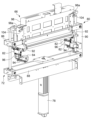
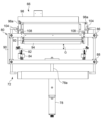
- FIGS. 9 and 10 are diagrams showing the clearance adjusting mechanism 72 and its surroundings.
- 7 is a perspective view
- FIG. 8 is a side view seen in the width direction X
- FIGS. 9 and 10 are side views seen in the conveying direction Y from the downstream side.
- FIG. 9 shows the nip rollers 62, 64 and the UV lamp 66 for foil stamping lowered to the position for foil stamping, and FIG. is raised. i.e.
- the gap adjustment mechanism 72 includes an electric cylinder (pressing portion) 78, a nip roller support portion 80, two stoppers 82, and two stepping motors 84.
- the nip roller support section 80 includes an upper frame 86 , a lower frame 88 , a connecting frame 90 and two blocks 92 .
- the upper frame 86 and the lower frame 88 are separated from each other in the vertical direction and extend in the width direction X so as to overlap each other in plan view.
- the upper frame 86 is positioned above the transport guide 106 and the lower frame 88 is positioned below the transport guide 106 .
- the connecting frame 90 extends vertically and connects the upper frame 86 and the lower frame 88 at one end in the width direction.
- the two blocks 92 are fixed to the lower surface of the upper frame 86 on the right side and the left side in the width direction X, respectively.
- the two blocks 92 are positioned above the transport guide 106 and support both ends of the nip rollers 62 and 64 in a sandwiched manner.
- the electric cylinder 78 is provided below the nip roller support portion 80 .
- a rod 78 a of the electric cylinder 78 is connected to the lower frame 88 of the nip roller support portion 80 .
- the electric cylinder 78 raises and lowers the nip roller support portion 80 and thus the nip rollers 62 and 64 .
- the two stoppers 82 are provided on both sides in the width direction.
- the positions of the two stoppers 82 in the vertical direction can be individually adjusted by corresponding stepping motors 84 .
- the rotational driving force of the stepping motor 84 is transmitted to the drive shaft (ball screw) 96 via the transmission belt 94 .
- the stopper 82 ascends or descends depending on the direction of rotation.
- each of the two blocks 92 comes into contact with the corresponding stopper 82 and stops, restricting the further descent of the nip roller support portion 80 . That is, the position of the stopper 82 in the vertical direction determines the position of the nip rollers 62 and 64 in the vertical direction, and thus the size of the gap G is determined.
- the nip roller support portion 80 When the nip roller support portion 80 rises to a certain height position, the upper surface of the upper frame 86 of the nip roller support portion 80 contacts the rubber feet 108 fixed to the lower surface of the light source support portion 98 of the UV lamp 66 for foil stamping. When the nip roller support portion 80 is further raised, the ultraviolet lamp 66 for foil stamping supported by the nip roller support portion 80 is lifted. That is, the foil stamping ultraviolet lamp 66 is separated from the lamp stopper 104 and is not supported by the lamp stopper 104 . The foil stamping UV lamp 66 moves up and down together with the nip roller support 80 while being supported by the nip roller support 80 .
- the UV lamp 66 for foil stamping moves from the irradiation position (position shown in FIG. 9) where ultraviolet rays are irradiated toward the sheet during foil stamping to a retracted position (position shown in FIG. 10) that is farther from the conveying surface than the irradiation position. position) and can be retracted to a retraction position above the irradiation position.
- the control device 20 controls the electric cylinder 78 and the two stepping motors 84 to adjust the size of the gap G to the target size. Specifically, when the gap G is to be reduced, the control device 20 controls the two stepping motors 84 to lower the two stoppers 82 to a vertical position corresponding to the target size of the gap G, Subsequently, the electric cylinder 78 is controlled to lower the nip roller support portion 80 so as to contact the stopper 82 .
- the control device 20 controls the electric cylinder 78 to raise the nip rollers 62 and 64 to a position where the gap G is larger than the target size.
- the two stoppers 82 are controlled to rise to a vertical position corresponding to the size of the target gap G, and then the electric cylinder 78 is controlled to lower the nip roller support portion 80 so as to contact the stoppers 82 .
- FIGS. 11(a) to 11(f) are diagrams showing the operation of the foil stamping device 16 when performing foil stamping (first mode) in chronological order.
- FIG. 11(a) shows a state of waiting for the sheet S to reach the foil stamping section. 11A, the leading edge of the sheet S reaches the sheet detection sensor 77. In FIG. In FIG. 11(a), braking by the brake mechanisms 68 and 70 is applied.
- the sheet S1 is coated with varnish and semi-cured.
- the sheet S1 has a leading non-processing range Rcf, a processing range Rc, and a trailing non-processing range Rcr.
- the leading edge non-processing range Rcf, the processing range Rc, and the trailing edge non-processing range Rcr are arranged from the leading edge side of the sheet S in this order. Varnish is not applied to the leading edge unprocessed range Rcf and the trailing edge unprocessed range Rcr.
- the leading edge non-processing range Rcf is a range from the leading edge of the sheet S to the leading edge of the processing range Rc.
- the trailing edge non-processing range Rcr is a range from the trailing edge of the processing range Rc to the trailing edge of the sheet S.
- the processing range Rc is a range including the varnished area.
- the processing range Rc is the range in the transport direction Y from the leading end to the trailing end of the one region.
- the processing range Rc extends from the tip of the area where the tip of the plurality of areas is positioned furthest downstream to the rear end of the plurality of areas which is the furthest upstream. It is the range to the trailing edge of the region where it is located.
- the size of the gap G is adjusted to a first size G1 (eg, 3 mm).
- the first size is a size that prevents the web 52 from contacting the sheet S even if the sheet S exists in the gap G.
- FIG. 11B shows the state immediately before the leading edge of the processing range Rc of the sheet S enters the foil stamping section F.
- the size of the gap G is adjusted to a second size G 2 ( ⁇ first size G 1 ).
- the second size G2 is the size of the gap G corresponding to the thickness of the sheet S.
- the second size G2 is a size that allows the sheet S to enter the gap G, and a size that allows the web 52 to contact the sheet S with an appropriate contact pressure to achieve good foil stamping.
- the user may input the size of the gap corresponding to the thickness of the sheet S, and the controller 20 may acquire it as the second size G2.
- the controller 20 may calculate the second magnitude G2.
- control device 20 holds correspondence information in which various sheet thicknesses are associated with appropriate sizes of the gaps G corresponding to the various sheet thicknesses, and acquires the sheet thickness, for example.
- a sensor is provided at an appropriate position to acquire the thickness of the sheet, and a second size G that is the size of the gap G according to the thickness of the sheet is obtained based on the acquired thickness of the sheet and the correspondence information. 2 may be specified.
- the size of the gap G according to the thickness of the sheet may be the thickness of the sheet excluding the varnish.
- the timing for adjusting the gap G from the first size G1 to the second size G2, that is, the timing for lowering the nip rollers 62 and 64, is obtained by obtaining a pulse from an encoder interposed in the drive mechanism of the conveying roller 54.
- the pulse P1 is counted after the sheet detection sensor 77 detects the leading edge of the sheet S.
- the pulse P1 is determined based on the length in the transport direction of the leading edge unprocessed range Rcf obtained from the varnish data.
- the pulse P1 may be finely adjusted by a user's input according to the finishing state.
- the size of the gap G may be adjusted so that the leading edge of the sheet S reaches the second size G2 immediately before entering the foil stamping section F, but in this case, the web 52 is unnecessarily fed. Since the web 52 is wasted, preferably, the size of the gap G is adjusted so that the leading end of the processing area Rc reaches the second size G2 immediately before entering the foil stamping section F.
- the brake by the first brake mechanism 68 is released. do.
- the braking by the second braking mechanism 70 may be released substantially at the same time as the braking by the first braking mechanism 68, but preferably is released after a certain period of time after the braking by the first braking mechanism 68 is released.
- the timing for releasing the brake by the second brake mechanism 70 may be, for example, the moment when the state transitions to the state shown in FIG. 11(b). If the sheet enters the foil stamping section F while the foil remains loose in the state of FIG.
- the control device 20 controls the electric cylinder 78 to press the nip roller support portion 80 against the stopper 82, that is, downward. Specifically, the control device 20 controls the electric cylinder 78 so that the nip roller supporting portion 80 and the nip rollers 62 and 64 continue to move with the position where the gap G is zero as the target position. As a result, the nip roller support portion 80 is pressed toward the stopper 82, and the nip rollers 62 and 64 are pressed downward.
- the nip rollers 62 and 64 do not move upward, and the size of the gap G is maintained at the second size G2. It is possible to reliably bond the web 52 to the sheet.
- FIG. 11(c) is just before the tip of the processing range Rc enters the UV irradiation range U of the foil stamping UV lamp 66 .
- the ultraviolet lamp 66 for foil stamping starts lighting.
- the lighting is started at the timing when the pulse P2 is counted after the sheet detection sensor 77 detects the leading edge of the sheet S.
- the pulse P2 is determined based on the length in the transport direction of the leading edge unprocessed range Rcf obtained from the varnish data.
- the sheet S moves in contact with the web 52.
- the semi-cured varnish on the sheet S is irradiated with ultraviolet rays from the foil stamping ultraviolet lamp 66 .
- the varnish is fully cured by this irradiation.
- the fully cured varnish strongly bonds the foil of the web 52 and the sheet S.
- the web 52 is already separated near the leading end of the processing range Rc, but the foil adhered by the fully cured varnish remains in the varnished region on the sheet S. .
- FIG. 11(e) shows the state immediately after the rear end of the processing range Rc has left the irradiation range U of the foil stamping ultraviolet lamp 66 .
- the ultraviolet lamp 66 for foil stamping is turned off.
- the timing of turning off the light is the timing when the pulse P3 is counted after the sheet detection sensor 77 detects the leading edge of the sheet S.
- FIG. The pulse P3 is determined based on the lengths in the conveying direction of the leading edge unprocessed range Rcf and the processed range Rc obtained from the varnish data.
- FIG. 11(f) shows the state immediately after the rear end of the processing range Rc leaves the foil stamping section F.
- FIG. 11(f) braking by the braking mechanisms 68 and 70 is applied.
- the size of the gap G is returned to the first size G1.
- the timing for returning the gap G from the second size G2 to the first size G1, ie, the timing for raising the nip rollers 62 and 64, is determined after the sheet detection sensor 77 detects the leading edge of the sheet S, and then the pulse P4. is the timing of counting.
- the pulse P4 is determined based on the lengths in the conveying direction of the leading edge unprocessed range Rcf and the processed range Rc obtained from the varnish data.
- the size of the gap G may be adjusted so that the trailing edge of the sheet S reaches the first size G1 immediately after it leaves the foil stamping section F, but in this case, the web 52 is unnecessarily fed. Since the web 52 is wastefully consumed, the size of the gap G is preferably adjusted so that the rear end of the processing area Rc reaches the first size G1 immediately after coming out of the foil stamping section F. .
- the foil stamped sheet S is discharged to the stacker 18 (see FIGS. 1 and 2), and the foil stamping process for the sheet S is completed.
- FIGS. 11(a) to 11(f) are repeated until the number of sheets specified in the job data is processed.
- FIGS. 12(a) to 12(c) are diagrams showing in chronological order the operation of the foil stamping device 16 when web loading/exchange work is performed.
- the size of the gap G is adjusted to a first size G1.
- the nip roller supporting portion 80 (not shown in FIGS. 12(a) to 12(c)) and the nip rollers 62 and 64 are raised to increase the gap G.
- FIG. 12(a) shows a first size G1.
- the size of the gap G is the third size G 3 (>first size G 1 ).
- the nip roller supporting portion 80 comes into contact with the rubber leg 108 of the ultraviolet lamp 66 for foil stamping.
- FIG. 12(c) shows a state in which the nip roller support portion 80 and the UV lamp 66 for foil stamping are raised to the top, and the size of the gap G is the fourth size G 4 (>the third size G 3 ). In the state shown in FIG. 12(c), the web loading/replacement work such as routing the web 52 is carried out.
- the state shown in FIG. 12(a) is restored. That is, the size of the gap G is returned to the first size G1.
- the UV stamping lamp 66 descends with the nip rollers 62, 64, ie, along with the web path in the foil stamping section F, until the gap G reaches a third size G3.
- the ultraviolet lamp 66 for foil stamping is supported by the lamp stopper 104 and does not descend any further.
- the size of the gap G between the web path and the conveying surface in the foil stamping section F is adjusted according to the thickness of the sheet.
- the web 52 and the sheet can be brought into contact with an appropriate contact pressure, and good foil stamping can be achieved.
- the nip rollers 62 and 64 are pressed downward during foil stamping. Since the thickness is maintained at the second magnitude G2, the web 52 and the sheet S are brought into contact with each other with an appropriate contact pressure, and the web 52 can be reliably adhered to the sheet.
- the nip rollers 62, 64 that is, the web path and the foil stamping ultraviolet lamp 66 in the foil stamping section F can be retracted upward, which facilitates the web loading and replacement work.
- the UV lamp 66 for foil stamping can be vertically moved by the gap adjusting mechanism 72 that vertically moves the nip rollers 62 and 64 to adjust the size of the gap G.
- the number of driving sources can be reduced and the cost of the foil stamping device 16 can be reduced.
- the web 52 moves by contacting the moving sheet S. However, if a separate drive for moving the web 52 is provided, the web 52 is stopped in accordance with the on/off timing of the drive.
- the ultraviolet lamp 66 for foil stamping may be turned off during the time.
- a plurality of processing ranges Rc may be set for one sheet, and the turning on/off of the foil stamping UV lamp 66 may be controlled corresponding to each processing range Rc.
- the control of turning on the light just before the leading edge of the processing range Rc reaches the irradiation range U and turning off the light immediately after the rear end of the processing range Rc leaves the irradiation range U is applied to the plurality of processing ranges Rc.
- Each may be performed separately. By doing so, the time for irradiating the sheet S with ultraviolet rays can be shortened, and problems such as deformation of the sheet S due to the heat of the ultraviolet rays can be suppressed.
- the processing range Rc existing on the front end side and the processing range Rc existing on the rear end side thereof are adjacent to each other in the transport direction, and the rear end of the processing range Rc on the front end side and the rear end side of the processing range Rc on the front end side are adjacent to each other.
- the size of the gap G may be set to the first gap until the tip of the tip enters the foil stamping section F. While the first nip roller 62 and the second nip roller 64 are in the first gap, the web 52 is stopped without being sent.
- the light After exiting, the light is turned off while the first nip roller 62 and the second nip roller 64 are raised, and after the first nip roller 62 and the second nip roller 64 are lowered, the processing range Rc on the rear end side is turned off. It is preferable to turn on the light again before the tip enters the irradiation range U. By doing so, the length of web 52 to be fed can be reduced, leading to savings in foil.
- the ultraviolet lamp for main curing may be turned off immediately.
- the web 52 is irradiated with ultraviolet rays from the UV lamp 66 for foil stamping, it can withstand the irradiation for a very short time. may be turned on or off.
- the height positions of the two stoppers 82 may be adjusted individually.
- the two stoppers 82 may be moved to vertical positions corresponding to the thickness of the sheet, and the height positions of the two stoppers 82 may be individually finely adjusted while observing the finished product.
- the sheets are aligned in the width direction X on the registration reference guide 32, and the sheet is conveyed with reference to the side on which the registration reference guide 32 is provided (the right side in the width direction in FIG. 2). Therefore, when the width of the sheet is small, the sheet passes through one side in the width direction but does not pass through the other side in the width direction. can occur. Therefore, the user may input the width-direction size of the sheet or acquire it with an appropriate sensor, and the height positions of the two stoppers 82 may be adjusted based on the width-direction size of the sheet.
- control device 20 adjusts the height position of the stopper 82 on one side in the width direction so that the gap on one side in the width direction through which the sheet passes is larger than the gap on the other side in the width direction. It may be higher than the height position of the side stopper 82 . Further, for example, the control device 20 may make the gap on one side in the width direction larger than the gap on the other side in the width direction when the size of the sheet in the width direction is less than or equal to a predetermined value.
- the technical idea of the embodiment is not limited to the case of transferring foil to a sheet.
- the object to which the foil is transferred by the foil stamping device 16 may be other than the sheet.
- the web 52 that holds the foil usually has a transfer layer formed by vapor-depositing, coating, or attaching a metal, coloring material, or the like to a base film, and the transfer layer becomes a "foil" that is a substance for transfer.
- a release layer, an adhesive layer, or the like may be added so that the transfer layer has excellent adhesiveness during transfer and excellent peelability from the base film.
- the elongated base sheet carrying the transfer substance is not limited to a film, and may be a belt-shaped woven fabric or the like as long as it can hold the transfer substance and transfer it to the transferred material in the transfer section.
- the transfer material held by the web 52 and transferred in the transfer section is not limited to "foil", and may be a thin layer other than metal.
- a transfer material such as ink may be applied to a web, which is a substrate, such as an ink ribbon.
- the elongated base sheet carrying the transfer substance is not limited to a film, and may be a belt-shaped woven fabric or the like as long as it can hold the transfer substance and transfer it to the transferred material in the transfer section.
- a web having fine unevenness formed on the surface and a varnish applied to the surface of an object to be transferred are brought into close contact with each other, and the uneven shape is varnished.
- It may be a transfer device that performs a process called “laminating”, in which a surface shape formed by fine unevenness of a web is transferred onto a material to be transferred by copying onto the surface.
- lamination coating if the gap G is too large relative to the thickness of the material to be transferred, the contact pressure between the web and the varnish is too low, resulting in insufficient transfer of the surface shape, or no transfer of the surface shape at all.
- the material to be transferred cannot enter the gap G, or even if it does enter, the varnish spreads and loses its shape. According to the present invention, it is possible to obtain a transfer device that can appropriately transfer the surface shape without these problems.
- the electric cylinder 78 prevents the nip rollers 62 and 64 from escaping upward even during transfer and maintains the predetermined gap G, so that the surface shape of the web 52 can be reliably transferred to the varnish on the transferred material. be able to.
Abstract
Provided is a transfer apparatus that transfers, in a transfer section, the surface shape of a transfer web or a transfer material to a transfer target object carried along a carrying surface, from the transfer web carried along a web route. The transfer apparatus includes: a gap adjustment mechanism that adjusts the size of a gap between the carrying surface and the web route in the transfer section; and a control device that controls the gap adjustment mechanism to adjust the size of the gap to a size corresponding to the thickness of the transfer target object.
Description
本発明は、転写装置に関する。
The present invention relates to a transfer device.
ロール・ツー・ロールで搬送される転写ウェブから箔などの転写用物質をシートなどの被転写物に対して転写する転写装置が知られている。また、ラミコート加工等と呼ばれる、被転写物の表面に塗布された硬化可能なコート層と転写ウェブとを密着させて、転写ウェブの表面の凹凸によって形成される表面形状をコート層に写し取ることで転写ウェブの表面形状を被転写物に対して転写する加工を行う転写装置も知られている。
A transfer device is known that transfers a transfer material such as foil from a transfer web conveyed by roll-to-roll to a transferred material such as a sheet. In addition, a curable coating layer applied to the surface of the material to be transferred and the transfer web are brought into close contact with each other, and the surface shape formed by the irregularities on the surface of the transfer web is transferred to the coating layer, which is called a lamination coating process. There is also known a transfer device that transfers the surface shape of a transfer web to a material to be transferred.
本発明者らは、転写装置について鋭意研究を重ねた結果、転写装置の商品価値を高める上で、転写区間における転写ウェブのウェブ経路と被転写物の搬送面との隙間である転写区間隙間の管理について改善の余地があることを認識するに至った。
As a result of intensive research on the transfer device, the present inventors found that the transfer section gap, which is the gap between the web path of the transfer web in the transfer section and the conveying surface of the material to be transferred, in order to increase the commercial value of the transfer device. We have come to recognize that there is room for improvement in terms of management.
本発明はこうした状況においてなされたものであり、そのある態様の例示的な目的のひとつは、適切な転写区間隙間の管理により商品価値を高めた転写装置を提供することにある。
The present invention has been made in such a situation, and one of the exemplary purposes of certain aspects thereof is to provide a transfer device with enhanced commercial value through appropriate management of the transfer interval gap.
上記課題を解決するために、本発明のある態様の転写装置は、搬送面に沿って搬送される被転写物に、ウェブ経路に沿って搬送される転写ウェブから、転写区間において転写用物質または転写ウェブの表面形状を転写する転写装置であって、転写区間における搬送面とウェブ経路との隙間の大きさを調整する隙間調整機構と、隙間調整機構を制御し、隙間の大きさを、被転写物の厚さに応じた大きさに調整する制御装置と、を備える。
In order to solve the above problems, a transfer device according to one aspect of the present invention transfers a transfer material or a transfer material from a transfer web conveyed along a web path to a transfer material conveyed along a conveying surface in a transfer section. A transfer device for transferring the surface shape of a transfer web, comprising: a gap adjustment mechanism for adjusting the size of a gap between a conveying surface and a web path in a transfer section; and a control device that adjusts the size according to the thickness of the transferred material.
本発明の別の態様もまた、転写装置である。この装置は、転写ウェブをウェブ経路に沿って搬送するウェブ搬送機構と、被転写物を搬送する被転写物搬送機構と、転写ウェブの転写用物質または転写ウェブの表面形状が被転写物に転写される転写区間において、ウェブ経路に対して被転写物搬送機構の搬送面とは反対側の照射位置から紫外線を照射する紫外線光源ユニットと、転写区間におけるウェブ経路を昇降することによって、転写区間におけるウェブ経路と搬送面との隙間を調整する隙間調整機構と、を備える。紫外線光源ユニットは、隙間の大きさが閾値を超えると、ウェブ経路とともに昇降する。
Another aspect of the present invention is also a transfer device. This apparatus includes a web transport mechanism for transporting a transfer web along a web path, a transfer target transport mechanism for transporting a transfer target, and a transfer material of the transfer web or the surface shape of the transfer web being transferred to the transfer target. An ultraviolet light source unit that irradiates ultraviolet light from an irradiation position on the opposite side of the conveying surface of the transferred material conveying mechanism with respect to the web path in the transfer section where the transfer section is moved up and down the web path in the transfer section. a gap adjusting mechanism for adjusting the gap between the web path and the conveying surface. The UV light source unit moves up and down with the web path when the gap size exceeds a threshold value.
本発明によれば、商品価値を高めた転写装置を提供できる。
According to the present invention, a transfer device with enhanced commercial value can be provided.
以下、本発明を好適な実施の形態をもとに図面を参照しながら説明する。実施の形態は、発明を限定するものではなく例示であって、実施の形態に記述されるすべての特徴やその組み合わせは、必ずしも発明の本質的なものであるとは限らない。各図面に示される同一または同等の構成要素、部材、処理には、同一の符号を付するものとし、適宜重複した説明は省略する。
BEST MODE FOR CARRYING OUT THE INVENTION The present invention will be described below based on preferred embodiments with reference to the drawings. The embodiments are illustrative rather than limiting the invention, and not all features and combinations thereof described in the embodiments are necessarily essential to the invention. The same or equivalent constituent elements, members, and processes shown in each drawing are denoted by the same reference numerals, and duplication of description will be omitted as appropriate.
本発明を具体的に説明する前に、概要を述べる。
Before describing the present invention in detail, an overview will be given.
転写区間における転写ウェブと被転写物の搬送面との隙間は、当然ながら被転写物が入りうる大きさである必要があるが、隙間が大きすぎると転写ウェブが被転写物と接触しないまたは転写ウェブと被転写物との接触圧が低すぎてしまい、隙間が小さすぎると転写ウェブと被転写物との接触圧が高すぎてしまい、いずれの場合も接触不良が生じうる。その結果、転写不良あるいは搬送不良が生じうる。
The gap between the transfer web and the conveying surface of the material to be transferred in the transfer section must, of course, be large enough for the material to be transferred to enter. If the contact pressure between the web and the material to be transferred is too low, and if the gap is too small, the contact pressure between the transfer web and the material to be transferred is too high, and poor contact may occur in either case. As a result, transfer failure or transport failure may occur.
これに対し本発明の転写装置は、転写区間における転写ウェブのウェブ経路と被転写物の搬送面との隙間である転写区間隙間の大きさを、被転写物の厚さに応じた大きさに調整する。これにより、良好な転写を実現することが可能となる。
On the other hand, in the transfer device of the present invention, the size of the transfer section gap, which is the gap between the web path of the transfer web in the transfer section and the conveying surface of the material to be transferred, is adjusted to the size corresponding to the thickness of the material to be transferred. adjust. This makes it possible to achieve good transfer.
また、被転写物の転写位置に紫外線硬化性ニスを塗布し、そのニスのタック性を利用して転写ウェブから被転写物に転写物質を転写する場合、転写区間において紫外線光源ユニットから転写ウェブに紫外線を照射してニスを硬化させる必要がある。紫外線光源ユニットは、転写ウェブに比較的近い距離、すなわち、硬化に必要な量の紫外線が届く距離から紫外線を照射する。紫外線光源ユニットがこの位置にあると、例えば転写ウェブの装着や交換の際に、紫外線光源ユニットと被転写物の搬送面とのわずかな隙間に転写ウェブを通さなければならず、作業しにくい。また例えば、故障個所の修理や保守点検等で紫外線光源ユニットと被転写物の搬送面とのわずかな隙間にアクセスする際の作業もしにくい。つまりメンテナンスもしにくい。
Further, when applying an ultraviolet curable varnish to the transfer position of the material to be transferred and using the tackiness of the varnish to transfer the transfer material from the transfer web to the material to be transferred, the ultraviolet light source unit transfers to the transfer web in the transfer section. It is necessary to irradiate the varnish with ultraviolet rays to cure it. The UV light source unit irradiates UV light from a relatively close distance to the transfer web, ie, a distance where the necessary amount of UV light for curing can reach. If the ultraviolet light source unit is in this position, for example, when attaching or replacing the transfer web, the transfer web must be passed through a small gap between the ultraviolet light source unit and the conveying surface of the material to be transferred, making the work difficult. In addition, for example, it is difficult to access a small gap between the ultraviolet light source unit and the transport surface of the transferred material for repairing a faulty part or maintenance inspection. In other words, it is difficult to maintain.
これに対し本発明の転写装置は、転写区間における転写ウェブのウェブ経路に加えて紫外線光源ユニットも上昇させることが可能である。これにより、ウェブ装着・交換作業やメンテナンスがしやすくなる。
In contrast, the transfer device of the present invention can raise the ultraviolet light source unit in addition to the web path of the transfer web in the transfer section. This makes it easier to install/replace the web and perform maintenance.
以下、本発明の実施の形態について具体的に説明する。なお、以下では、転写装置が箔押し装置すなわち被転写物に箔を転写する装置である場合を例に説明するが、これには限定されず、転写装置は箔以外の転写用物質を被転写物に転写する装置であってもよい。また、転写装置は、硬化可能なコート層と転写ウェブとを密着させて転写ウェブの表面形状を被転写物に転写するいわゆるラミコート加工を行う装置であってもよい。
Hereinafter, embodiments of the present invention will be specifically described. In the following description, the case where the transfer device is a foil stamping device, i.e., a device that transfers foil to a transferred object will be described as an example. It may be a device that transfers to Further, the transfer device may be a device that performs a so-called lamination coating process in which a hardenable coating layer and a transfer web are brought into close contact with each other to transfer the surface shape of the transfer web to the material to be transferred.
図1、2は、実施の形態に係る箔押し装置16が用いられる印刷システム10を模式的に示す図である。図1は側面図であり、図2は平面図である。印刷システム10は、シートを搬送しながらシートに所定の印刷を施す装置である。シートの素材は、紙、布、樹脂、金属などさまざまである。以降、シートが搬送される方向(図1、2において右から左に向かう方向)を搬送方向Y、搬送方向Yと直交する方向(図1において紙面に直交する方向であって図2における上下方向)を幅方向Xと呼ぶ。また、幅方向Xについて、上流側から搬送方向Yに見て右側を幅方向Xにおける右側、左側を幅方向Xにおける左側と呼ぶ。また、シートについて、搬送方向Yにおけるシートの下流側の端縁をシートの先端、上流側の端縁をシートの後端と呼ぶ。
1 and 2 are diagrams schematically showing a printing system 10 in which a foil stamping device 16 according to an embodiment is used. 1 is a side view and FIG. 2 is a plan view. The printing system 10 is a device that applies predetermined printing to a sheet while conveying the sheet. Sheets are made of various materials such as paper, cloth, resin, and metal. Hereinafter, the direction in which the sheet is conveyed (the direction from right to left in FIGS. 1 and 2) is the conveying direction Y, and the direction perpendicular to the conveying direction Y (the direction perpendicular to the paper surface in FIG. 1 and the vertical direction in FIG. 2). ) is called the width direction X. In addition, regarding the width direction X, the right side in the width direction X as viewed from the upstream side in the transport direction Y is called the right side in the width direction X, and the left side is called the left side in the width direction X. Regarding the sheet, the edge on the downstream side in the transport direction Y is called the leading edge of the sheet, and the edge on the upstream side is called the trailing edge of the sheet.
印刷システム10は、シートを1枚ずつ給紙する給紙装置12と、1枚ずつ給紙されるシートにニスを塗布するニス塗布装置14と、ニスのタック性を利用してシート上のニスに箔を転写することで箔押しを行う箔押し装置16と、シートを蓄積するスタッカ18と、印刷システム10を統合的に制御する制御装置20と、を備える。給紙装置12、ニス塗布装置14、箔押し装置16、スタッカ18は、搬送方向Yに上流側(図1、2では右側)からこの順に一列に並ぶ。制御装置20は、給紙装置12、ニス塗布装置14、箔押し装置16およびスタッカ18とネットワーク2を介して接続される。
The printing system 10 includes a sheet feeding device 12 that feeds sheets one by one, a varnish applying device 14 that applies varnish to the sheets that are fed one by one, and a varnish on the sheet using the tackiness of varnish. a foil stamping device 16 that performs foil stamping by transferring foil to a sheet; a stacker 18 that accumulates sheets; The paper feeding device 12, the varnish coating device 14, the foil stamping device 16, and the stacker 18 are arranged in a row in this order from the upstream side (the right side in FIGS. 1 and 2) in the transport direction Y. As shown in FIG. The control device 20 is connected to the paper feeding device 12 , the varnish coating device 14 , the foil stamping device 16 and the stacker 18 via the network 2 .
給紙装置12は、フィーダ22と、コロナ処理部26と、レジスト部24と、を備える。フィーダ22は、テーブル28と、吸着ヘッド30と、を含む。テーブル28にはシートが積載される。テーブル28は、昇降可能に構成される。吸着ヘッド30は、テーブル28に積載されたシートを上から順に1枚ずつ送り出す。
The paper feeding device 12 includes a feeder 22 , a corona treatment section 26 and a registration section 24 . Feeder 22 includes table 28 and suction head 30 . Sheets are stacked on the table 28 . The table 28 is configured to be movable up and down. The suction head 30 sends out the sheets stacked on the table 28 one by one in order from the top.
レジスト部24は、幅方向Xの一端側(図示の例では幅方向Xにおける右側)に設けられるレジスト基準ガイド32を含む。レジスト基準ガイド32は、幅方向Xに直交し、搬送方向Yに延びるガイド面32aを有する。レジスト部24は、フィーダ22が送り出したシートを、ガイド面32aに突き当てることによって、そのシートの幅方向Xの位置を揃える。
The resist section 24 includes a resist reference guide 32 provided on one end side in the width direction X (the right side in the width direction X in the illustrated example). The registration reference guide 32 has a guide surface 32a that is perpendicular to the width direction X and extends in the transport direction Y. As shown in FIG. The registration unit 24 aligns the positions of the sheets in the width direction X by abutting the sheets fed by the feeder 22 against the guide surface 32a.
コロナ処理部26は、搬送路34の上方に配置される電極36と、電極36と上下で対向するように搬送路34の下方に配置される誘電ローラ38と、を含む。コロナ処理部26は、電極36と誘電ローラ38との間のコロナ放電により、フィーダ22が送り出したシートの表面改質を行う。なお、エア吸引部40によってシートを搬送路34に吸着させた状態で搬送すると、電極36とシートとの距離が一定となり、コロナ放電が安定する。エア吸引部40は、不図示の排気用ブロワーの吸引口の一つを配置して負圧を発生させるものであるが、吸引ファンを配置して負圧を発生させる構成としてもよい。誘電ローラ38は、コロナ処理部26の筐体に対して回転可能でもよいし、固定でもよい。さらに、電極36との間にコロナ放電を生じさせるものであれば、その形状はローラ状に限らない。コロナ処理部26は、レジスト部24の上流側に配置されてもよい。
The corona treatment unit 26 includes an electrode 36 arranged above the conveying path 34 and a dielectric roller 38 arranged below the conveying path 34 so as to face the electrode 36 vertically. The corona treatment unit 26 modifies the surface of the sheet fed from the feeder 22 by corona discharge between the electrode 36 and the dielectric roller 38 . If the sheet is conveyed while being attracted to the conveying path 34 by the air suction unit 40, the distance between the electrode 36 and the sheet becomes constant and the corona discharge is stabilized. The air suction unit 40 generates a negative pressure by arranging one of the suction ports of an exhaust blower (not shown), but it may be configured to generate a negative pressure by arranging a suction fan. Dielectric roller 38 may be rotatable or fixed with respect to the housing of corona treatment station 26 . Furthermore, the shape is not limited to a roller shape as long as it causes corona discharge between itself and the electrode 36 . The corona treatment section 26 may be arranged upstream of the resist section 24 .
ニス塗布装置14は、シートセンサ42と、一対のCCDセンサ44と、少なくとも1つのニス吐出部46と、半硬化用紫外線ランプ48と、本硬化用紫外線ランプ50と、を含む。一対のCCDセンサ44、ニス吐出部46、半硬化用紫外線ランプ48、本硬化用紫外線ランプ50は、この順に上流側から並ぶように配置される。CCDセンサ44は、CMOSセンサであってもよい。図示の例では、ニス塗布装置14は3つのニス吐出部46を含んでいるが、これには限定されず、ニス塗布装置14は幅方向Xの少なくとも印刷が必要な領域の全域にわたって延在する1つのニス吐出部46を含んでもよいし、2つまたは4つ以上のニス吐出部46を含んでもよい。半硬化用紫外線ランプ48および本硬化用紫外線ランプ50には紫外線を照射するLEDを用いるが、紫外線を照射するものであれば、電球や蛍光灯などの他の光源であってもよい。光源は出力調整可能なものが望ましい。
The varnish application device 14 includes a sheet sensor 42 , a pair of CCD sensors 44 , at least one varnish discharger 46 , a semi-curing UV lamp 48 , and a full-curing UV lamp 50 . A pair of CCD sensors 44, a varnish discharger 46, a semi-curing ultraviolet lamp 48, and a full-curing ultraviolet lamp 50 are arranged in this order from the upstream side. The CCD sensor 44 may be a CMOS sensor. In the illustrated example, the varnishing device 14 includes three varnish dispensing units 46, but is not limited to this, and the varnishing device 14 extends over at least the entire area in the width direction X where printing is required. One varnish dispenser 46 may be included, or two or four or more varnish dispensers 46 may be included. The semi-curing UV lamp 48 and the main curing UV lamp 50 are LEDs that emit UV rays, but other light sources such as light bulbs and fluorescent lamps may be used as long as they emit UV rays. It is desirable that the light source has an adjustable output.
シートセンサ42は、給紙装置12から給紙されたシートを検出する。
The sheet sensor 42 detects sheets fed from the sheet feeding device 12 .
ニス吐出部46は、特に限定しないがライン型のインクジェットヘッドである。ニス吐出部46は、シートセンサ42によるシートの先端エッジの検出をトリガとして、ニス吐出データに従って紫外線硬化性ニスを吐出し、シートに紫外線硬化性ニスを塗布する。ニス吐出データは、シートのどこにニスを塗布するのかを示すデータである。
The varnish ejection unit 46 is a line-type inkjet head, although not particularly limited. The varnish discharger 46 is triggered by the detection of the leading edge of the sheet by the sheet sensor 42, and discharges ultraviolet curable varnish according to the varnish discharge data to apply the ultraviolet curable varnish to the sheet. The varnish discharge data is data indicating where on the sheet the varnish is to be applied.
給紙装置12が給紙するシートには、予め、下地画像と、下地画像の位置を特定する基準となる複数のレジストレーションマークとが印刷されていてもよい。ニス塗布装置14は、シートにおけるニスの塗布部分を規定するニス吐出データに従って、下地画像と所定の関係を有するようにニスを塗布するものであり、例えば下地画像に重なるように、ニスを塗布してもよい。
A base image and a plurality of registration marks that serve as references for specifying the position of the base image may be printed in advance on the sheet fed by the paper feeding device 12 . The varnish applicator 14 applies varnish so as to have a predetermined relationship with the base image according to varnish discharge data that defines the varnish applied portion of the sheet. may
ここで、シートの下地画像がずれていたり歪んでいたりすることもあり得る。したがって、下地画像と所定の関係を有するようにニスを塗布する場合は、ずれや歪みを考慮してニス吐出データを補正する必要がある。例えば、CCDセンサ44が、シートセンサ42によるシートの検出をトリガとしてシートを撮像し、制御装置20がCCDセンサ44による撮像データを画像解析し、複数のレジストレーションマークの理論位置との相違により、レジストレーションマークに囲まれた領域のニス吐出データを補正してもよい。なお、当該補正には、本出願人が先に出願した特開2016-083898号公報に記載の方法を適用できる。
Here, the base image of the sheet may be misaligned or distorted. Therefore, when applying varnish so as to have a predetermined relationship with the background image, it is necessary to correct the varnish ejection data in consideration of deviation and distortion. For example, the CCD sensor 44 captures an image of the sheet triggered by the detection of the sheet by the sheet sensor 42, the control device 20 analyzes the image data captured by the CCD sensor 44, and the difference from the theoretical positions of the plurality of registration marks results in: The varnish ejection data in the area surrounded by the registration marks may be corrected. Note that the method described in Japanese Patent Laid-Open No. 2016-083898 previously filed by the present applicant can be applied to this correction.
半硬化用紫外線ランプ48は、シート上のニスに出力が比較的抑制された紫外線を照射し、ニスを半硬化させる。半硬化は、ニスの流動性を低下させつつも完全には硬化させない程度に軽く(例えばさらに硬化させることができる状態に)硬化させることをいう。
The semi-curing ultraviolet lamp 48 irradiates the varnish on the sheet with ultraviolet rays whose output is relatively suppressed, thereby semi-curing the varnish. Semi-curing refers to lightly curing the varnish to such an extent that the fluidity of the varnish is reduced but the varnish is not completely cured (for example, to a state in which further curing is possible).
半硬化状態のニスは、箔押し装置16において本硬化される。シートに箔押ししないときは、通常、半硬化用紫外線ランプ48をオフにするか、あるいは出力を極小にする。しかし、箔押ししないときであっても半硬化用紫外線ランプ48を使用してもよい。例えば、シート上に塗布したニスが滲みやすい場合には、半硬化用紫外線ランプ48をオンにし、半硬化させておくことによって滲みを抑える効果がある。
The semi-cured varnish is fully cured in the foil stamping device 16 . When the sheet is not being foil stamped, the UV semi-curing lamp 48 is normally turned off or minimized. However, the semi-curing ultraviolet lamp 48 may be used even when foil stamping is not performed. For example, if the varnish applied to the sheet tends to bleed, turning on the semi-curing ultraviolet lamp 48 to semi-cure the varnish has the effect of suppressing bleed.
本硬化用紫外線ランプ50は、シートに塗布されたニスに紫外線を照射し、ニスを本硬化させる。シートに箔押しする(すなわち箔を転写する)ときは、本硬化用紫外線ランプ50をオフにする。図示していないが、本硬化用紫外線ランプ50の周りの空気を排気するための排気口を有する。この排気口には排気流を発生させるためのファンが設けられる。このファンの排気方向上流側に、ファンと間隙を空けて、紫外線照射により発生したオゾンを吸着するためのオゾン吸着フィルタが設けられる。
The final curing ultraviolet lamp 50 irradiates the varnish applied to the sheet with ultraviolet rays to fully cure the varnish. When foil stamping (that is, transferring the foil) to the sheet, the main curing UV lamp 50 is turned off. Although not shown, it has an exhaust port for exhausting the air around the UV lamp 50 for main curing. A fan is provided at the exhaust port to generate an exhaust flow. An ozone adsorption filter for adsorbing ozone generated by ultraviolet irradiation is provided upstream of the fan in the exhaust direction with a gap from the fan.
つまり、シートに箔押しするときは、半硬化用紫外線ランプ48によってニスを半硬化させ、箔押し装置16の箔押し用紫外線ランプ66によって半硬化状態のニスを本硬化させる。この場合、本硬化用紫外線ランプ50はオフにする。シートを箔押ししないすなわちシートにニスを塗布するだけのときは、本硬化用紫外線ランプ50でニスを本硬化させる。この場合、半硬化用紫外線ランプ48および箔押し装置16の箔押し用紫外線ランプ66はオフにする。半硬化用紫外線ランプ48は完全にオフにせず、出力を極小としてもよい。なお、上述したように、半硬化用紫外線ランプ48は、箔押ししないときでもオンにすることがある。また、箔押し用紫外線ランプ66の光源には紫外線を照射するLEDを用いるが、紫外線を照射するものであれば他の光源でもよい。
That is, when foil stamping the sheet, the varnish is semi-cured by the semi-curing UV lamp 48 and the semi-cured varnish is fully cured by the foil stamping UV lamp 66 of the foil stamping device 16 . In this case, the main curing ultraviolet lamp 50 is turned off. When the sheet is not foil-stamped, that is, only the varnish is applied to the sheet, the varnish is fully cured by the UV lamp 50 for final curing. In this case, the semi-curing ultraviolet lamp 48 and the foil stamping ultraviolet lamp 66 of the foil stamping device 16 are turned off. The semi-curing ultraviolet lamp 48 may not be completely turned off, and the output may be minimized. As described above, the semi-curing ultraviolet lamp 48 may be turned on even when foil stamping is not performed. Further, although an LED for irradiating ultraviolet rays is used as the light source of the ultraviolet lamp 66 for foil stamping, other light sources may be used as long as they irradiate ultraviolet rays.
図3は、ニス吐出部46によってシートS上に塗布され、半硬化用紫外線ランプ48によって半硬化されたニス層100、102を示す図である。100a、102aは硬化した硬化部分、100b、102bは硬化が十分ではない未硬化部分である。硬化部分100a、102aは各々ニス層100、102の内部を占め、未硬化部分100b、102bは各々ニス層100、102の表層部を占める。外気に触れる表層部の方が、酸素阻害の影響により硬化しにくいためである。
FIG. 3 is a diagram showing the varnish layers 100 and 102 applied on the sheet S by the varnish discharger 46 and semi-cured by the semi-curing ultraviolet lamp 48. FIG. Cured portions 100a and 102a are cured, and uncured portions 100b and 102b are not sufficiently cured. The cured portions 100a, 102a occupy the interior of the varnish layers 100, 102, respectively, and the uncured portions 100b, 102b occupy the surface layers of the varnish layers 100, 102, respectively. This is because the surface layer exposed to the outside air is less likely to harden due to the influence of oxygen inhibition.
図3(a)(b)はともに、ニス層100、102がすべて硬化しない程度に紫外線の出力を抑制して形成された半硬化状態であるが、図3(a)の場合は図3(b)の場合よりも、半硬化用紫外線ランプ48の出力が相対的に強いので、ニス層102よりもニス層100の方が硬化が表層部の近くにまで達している。したがってニス層100はニス層102よりも形状が安定し、表層部は流動はしないものの完全に硬化はしておらず、タック性を有した状態になっている。一方で、ニス層102はニス層100に対し、表層部のタック性はほとんど無く流動性を有し、特に上方の部分の流動性が高い。したがって半硬化後も上方のニスが流動し、徐々に上面が平らになるレベリング効果を発揮する。
Both FIGS. 3(a) and 3(b) show semi-cured states formed by suppressing the output of ultraviolet rays to such an extent that the varnish layers 100 and 102 are not completely cured. Since the output of the semi-curing ultraviolet lamp 48 is relatively stronger than in the case of b), the varnish layer 100 is cured closer to the surface layer than the varnish layer 102 is. Therefore, the varnish layer 100 is more stable in shape than the varnish layer 102, and although the surface layer does not flow, it is not completely hardened and has tackiness. On the other hand, the varnish layer 102 has almost no tackiness in the surface layer portion and has fluidity, and the fluidity in the upper portion is particularly high. Therefore, even after semi-hardening, the upper varnish flows and the upper surface gradually becomes flat, exhibiting a leveling effect.
半硬化状態のニスは、本硬化用紫外線ランプ50または箔押し装置16において、改めて紫外線が照射され、本硬化される。本硬化とは、ニス層100、102の全ての部分が完全に硬化されることをいう。半硬化状態のニス層100、102とも、シートSに接着している部分はそのほとんどが硬化部分100a、102aが占めるため、接着部が安定する。したがって、本硬化までの間に、ニス層100、102がシートS上に滲んでシート面方向(矢印A方向)に広がるのを抑制できるため、シートSの面方向の形状が安定する。
The semi-cured varnish is again irradiated with ultraviolet rays in the final curing ultraviolet lamp 50 or the foil stamping device 16 to be fully cured. Full curing means that all portions of the varnish layers 100 and 102 are completely cured. Since most of the portions of the semi-cured varnish layers 100 and 102 that are adhered to the sheet S are occupied by the cured portions 100a and 102a, the adhered portions are stabilized. Therefore, the varnish layers 100 and 102 can be prevented from bleeding onto the sheet S and spreading in the sheet surface direction (arrow A direction) until the main curing, so that the shape of the sheet S in the surface direction is stabilized.
この半硬化用紫外線ランプ48の位置を、シートの搬送方向に沿って移動可能に構成し、ニス吐出部46との距離を調整可能としてもよい。ニス吐出部46によりニスを塗布してから半硬化までの間はニスが広がり、より高いレベリング効果が得られる。半硬化用紫外線ランプ48とニス吐出部46との距離を調整可能とすることにより、ニスの広がりを止めるタイミングを調整可能とし、レベリングと形状の安定のバランスを調整することができる。ニス層が厚い場合はニスの体積が大きい分ニスの広がりが大きいため、半硬化用紫外線ランプ48をニス吐出部46に近づけ、早めにニスの広がりを抑制するのが良い。ニス層が薄い場合は、半硬化用紫外線ランプ48をニス吐出部46から遠ざけて、レベリングの時間を十分にとるのが良い。また、文字等の比較的シャープさが要求される場合は、半硬化用紫外線ランプ48をニス吐出部46に近づけ、早めにニスの広がりを抑制するのが良い。
The position of the semi-curing ultraviolet lamp 48 may be configured to be movable along the sheet conveying direction, and the distance from the varnish discharge section 46 may be adjusted. After the varnish is applied by the varnish discharger 46, the varnish spreads until the varnish is semi-cured, so that a higher leveling effect can be obtained. By making it possible to adjust the distance between the semi-curing ultraviolet lamp 48 and the varnish discharge part 46, it is possible to adjust the timing of stopping the spreading of the varnish, and to adjust the balance between leveling and shape stability. If the varnish layer is thick, the spread of the varnish is large because the volume of the varnish is large. When the varnish layer is thin, it is preferable to move the semi-curing ultraviolet lamp 48 away from the varnish discharge portion 46 to allow sufficient time for leveling. Further, when relatively sharp characters are required, it is preferable to bring the semi-curing ultraviolet lamp 48 close to the varnish discharge portion 46 to suppress the spreading of the varnish early.
箔押し装置16は、ウェブ(転写ウェブ)52をロール・ツー・ロールで搬送する。ウェブ52は、フィルム(基体シート)に箔(例えば金属箔)が保持された箔保持フィルムである。箔押し装置16では、シート上の半硬化状態のニスのタック性を利用して、当該ニスにウェブ52が保持する箔を接着させる。そして、箔がウェブ52に保持され、かつ、シート上のニスに接着した状態で、箔押し用紫外線ランプ66によって、箔が接着した半硬化状態のニスに紫外線を照射し、ニスを本硬化させる。これにより、ウェブ52が箔を保持する力よりも本硬化したニスが箔を接着する力の方が強い状態となる。この状態でシートとウェブ52とを分離させることで、ウェブ52に保持されていた箔を、シート上のニスが塗布された部分に転写できる。
The foil stamping device 16 conveys the web (transfer web) 52 roll-to-roll. The web 52 is a foil holding film in which a foil (for example, metal foil) is held on a film (base sheet). The foil stamping device 16 uses the tackiness of the semi-cured varnish on the sheet to adhere the foil held by the web 52 to the varnish. Then, while the foil is held on the web 52 and adhered to the varnish on the sheet, the UV lamp 66 for foil stamping irradiates the semi-cured varnish to which the foil is adhered with ultraviolet rays to fully cure the varnish. As a result, the force of the fully cured varnish to adhere the foil is stronger than the force of the web 52 to hold the foil. By separating the sheet and the web 52 in this state, the foil held by the web 52 can be transferred to the varnished portion of the sheet.
スタッカ18は、箔押し装置16から搬出されたシートを蓄積する。
The stacker 18 accumulates the sheets carried out from the foil stamping device 16.
制御装置20は、例えばPCなどの情報処理端末である。制御装置20は、印刷ジョブの定義についての入力を受け付ける。制御装置20は、所定のジョブ管理画面を表示し、当該ジョブ管理画面を介して、ジョブの定義についての入力を受け付けてもよい。ジョブの定義には、例えば、印刷を施すシートの枚数(印刷部数)、印刷を施すシートのシートサイズ、ニスデータ、箔押しの有無、が含まれる。制御装置20は、ジョブの定義に基づいて、給紙装置12、ニス塗布装置14および箔押し装置16を制御する。
The control device 20 is, for example, an information processing terminal such as a PC. The control device 20 accepts input regarding the definition of the print job. The control device 20 may display a predetermined job management screen and receive an input regarding the job definition via the job management screen. The job definition includes, for example, the number of sheets to be printed (the number of copies), the sheet size of the sheets to be printed, varnish data, and the presence or absence of foil stamping. The control device 20 controls the paper feeding device 12, the varnishing device 14 and the foil stamping device 16 based on the job definition.
制御装置20は、ニス吐出部46によりニスが吐出されたシートに対して紫外線を照射する工程で、使用する紫外線ランプの組み合わせが異なる、第1、第2、第3モードのいずれかを選択する。
The control device 20 selects one of the first, second, and third modes that use different combinations of ultraviolet lamps in the step of irradiating the sheet onto which the varnish has been discharged by the varnish discharger 46 with ultraviolet rays. .
第1モードでは、ニス吐出部46によりニスが吐出されたシートに対し、半硬化用紫外線ランプ48と、箔押し用紫外線ランプ66により紫外線を照射し、本硬化用紫外線ランプ50をオフとする。第2モードでは、ニス吐出部46によりニスが吐出されたシートに対し、半硬化用紫外線ランプ48と、本硬化用紫外線ランプ50により紫外線を照射し、箔押し用紫外線ランプ66をオフとする。第3モードでは、ニス吐出部46によりニスが吐出されたシートに対し、本硬化用紫外線ランプ50のみにより紫外線を照射し、半硬化用紫外線ランプ48と、箔押し用紫外線ランプ66をオフとする。
In the first mode, the semi-curing ultraviolet lamp 48 and foil stamping ultraviolet lamp 66 irradiate the sheet onto which varnish has been discharged by the varnish discharging unit 46, and the main curing ultraviolet lamp 50 is turned off. In the second mode, the semi-curing UV lamp 48 and the full-curing UV lamp 50 irradiate the sheet onto which varnish has been discharged by the varnish discharging unit 46, and the foil stamping UV lamp 66 is turned off. In the third mode, the sheet on which varnish has been discharged by the varnish discharger 46 is irradiated with ultraviolet rays only by the main curing ultraviolet lamp 50, and the semi-curing ultraviolet lamp 48 and foil stamping ultraviolet lamp 66 are turned off.
第1モードは、箔押し装置16において箔押しを行う場合に選択される。つまりシートに箔押しするときは、半硬化用紫外線ランプ48によってニスを半硬化させる。半硬化用紫外線ランプ48の出力は第2モードよりも相対的に強めとする。ニス層は図3(a)に示すように、表層部にタック性を有した状態で、その形状が安定する。このタック性を利用して、箔押し装置16においてニス層上面に箔が接着される。図3(a)に示すように未硬化状態が表層部だけであるので、箔が接着されても、未硬化部分が押しつぶされてシート面方向に広がることが無く、ニス層形状、特にシート面方向の形状が安定する。ニス層に箔が接着された状態で、箔押し用紫外線ランプ66によって半硬化状態のニスを本硬化させ、箔を確実にニス層に接着させる。その結果、箔押し後のシート上に形状の安定した箔が得られる。
The first mode is selected when foil stamping is performed by the foil stamping device 16 . That is, when foil stamping the sheet, the varnish is semi-cured by the semi-curing ultraviolet lamp 48 . The output of the semi-curing ultraviolet lamp 48 is relatively stronger than in the second mode. As shown in FIG. 3(a), the varnish layer has a tacky surface and is stable in shape. Using this tackiness, the foil is adhered to the upper surface of the varnish layer in the foil stamping device 16 . As shown in FIG. 3( a ), the uncured state is only the surface layer, so even if the foil is adhered, the uncured portion will not be crushed and spread in the sheet surface direction, and the shape of the varnish layer, especially the sheet surface, will not be expanded. The shape of the direction is stable. With the foil adhered to the varnish layer, the semi-cured varnish is fully cured by the UV lamp 66 for foil stamping to securely adhere the foil to the varnish layer. The result is a shape-stable foil on the sheet after foil stamping.
第2モードは、箔押ししない場合に選択される。第2モードでも、半硬化用紫外線ランプ48によってシート上のニスを半硬化させる。そして本硬化用紫外線ランプ50により本硬化される。箔押し装置16はシートが通過するだけで、箔押しは行われない。スタッカ18には、シートのニスを塗布すべき塗布部分にニス層が形成されたシートが排出される。半硬化用紫外線ランプ48の出力は、第1モードよりも相対的に弱めとしてもよい。ニス層は図3(b)に示すように、表層部上方に比較的多くの未硬化部分102bを残した状態となる一方で、シートSに接着している部分はそのほとんどが硬化部分102aが占め、接着部が安定する。したがって、ニスが広がるのを抑制でき、その形状が安定するとともに、本硬化用紫外線ランプ50まで搬送される間に、上方の、未硬化部分のニスが流動し、上面が平らになるレベリング効果を発揮するので、上面が平滑なニス層が得られる。
The second mode is selected when foil stamping is not used. In the second mode, the semi-curing ultraviolet lamp 48 semi-cures the varnish on the sheet. Then, the final curing is performed by the ultraviolet lamp 50 for final curing. The foil stamping device 16 only passes the sheet and does not stamp. A sheet having a varnish layer formed on the portion of the sheet to be varnished is discharged to the stacker 18 . The output of the semi-curing ultraviolet lamp 48 may be relatively weaker than in the first mode. As shown in FIG. 3B, the varnish layer leaves a relatively large number of uncured portions 102b above the surface layer, while most of the portions adhered to the sheet S are cured portions 102a. and stabilize the bond. Therefore, the spread of the varnish can be suppressed, the shape of the varnish is stabilized, and while the varnish is conveyed to the UV lamp 50 for main curing, the varnish in the upper, uncured portion flows and the upper surface is flattened to achieve a leveling effect. A varnish layer with a smooth upper surface is obtained.
また、第2モードでは紫外線の照射を半硬化用紫外線ランプ48と本硬化用紫外線ランプ50とに分担しているので、一つの光源により本硬化させる第3モードに比べて、紫外線によるシートへの熱照射とニスの紫外線硬化時の発熱による熱も分散させることができる。したがって、熱に敏感なシートがカール等の変形を起こしたり、下地画像が熱で変色あるいはトナーが融解するなどの不具合を抑制することができる。
In addition, in the second mode, since the semi-curing ultraviolet lamp 48 and the full-curing ultraviolet lamp 50 share the irradiation of ultraviolet rays, compared to the third mode in which the main curing is performed by one light source, the sheet is irradiated with ultraviolet rays. It is also possible to disperse the heat generated by the heat irradiation and the heat generated during UV curing of the varnish. Therefore, it is possible to suppress problems such as deformation of the heat-sensitive sheet such as curling, discoloration of the base image due to heat, and melting of the toner.
第3モードは、箔押ししない場合に選択される。第3モードでは、半硬化用紫外線ランプ48によるシート上のニスの半硬化は行われず、本硬化用紫外線ランプ50による本硬化のみが行われる。箔押し装置16はシートが通過するだけで、箔押しは行われない。スタッカ18には、シートの所定位置に所定形状のニス層が形成されたシートが排出される。半硬化が行われないので、本硬化用紫外線ランプ50まで搬送される間のレベリング効果がより高くなり、より上面が平滑なニス層が得られる。第3モードでは、半硬化用紫外線ランプ48を完全にオフにするのではなく、出力を極小としてもよい。
The third mode is selected when foil stamping is not used. In the third mode, semi-curing of the varnish on the sheet by the semi-curing ultraviolet lamp 48 is not performed, and only full curing by the main-curing ultraviolet lamp 50 is performed. The foil stamping device 16 only passes the sheet and does not stamp. A stacker 18 discharges a sheet having a varnish layer of a predetermined shape formed at a predetermined position of the sheet. Since semi-curing is not carried out, the leveling effect during transportation to the UV lamp 50 for main curing is enhanced, and a varnish layer with a smoother upper surface can be obtained. In the third mode, the output of the semi-curing ultraviolet lamp 48 may be minimized instead of being completely turned off.
第1、第2、第3モードを選択可能としたことにより、シートにニスを塗るだけの場合においても、より高品質なニス層を形成可能な装置が得られる。
By making it possible to select the first, second, and third modes, it is possible to obtain an apparatus that can form a higher quality varnish layer even when only coating a sheet with varnish.
制御装置20は、入力された印刷ジョブの定義に基づき、モードを選択する。印刷ジョブが箔押しを含むものであれば、第1モードが選択される。印刷ジョブが箔押しを含まないものであれば、第2または第3モードが選択される。
The control device 20 selects a mode based on the definition of the input print job. If the print job involves foil stamping, the first mode is selected. If the print job does not include foil stamping, the second or third mode is selected.
第2モードで得られたニス層は、半硬化を経ているので、ニス層がシート面方向に滲んで広がるのを防ぐ効果がある。したがって特に広がりの回避と、ニス層のシート面方向の形状の安定を必要とするジョブに適している。
Since the varnish layer obtained in the second mode has undergone semi-curing, it has the effect of preventing the varnish layer from bleeding and spreading in the sheet surface direction. Therefore, it is particularly suitable for jobs that require avoidance of spread and stability of the shape of the varnish layer in the direction of the sheet surface.
例えば、ニス層の厚みが厚い場合は、その分ニスが広がりやすい。したがって、ニス層の厚みが所定以上である領域を含む場合に第2モードを選択してもよい。また、ニス層の塗布すべき領域の面積が小さいオブジェクトを含む場合、あるいはニス層のシート面方向の最小の幅が狭い場合、隣接するニス層との間隔が小さい部分を含む場合は、ニス層の広がりによってニスを塗布した領域の形状が崩れやすい。したがって、印刷ジョブのうち、シート上のニスの塗布部分を規定するニスデータを画像解析し、ニスを塗布すべきオブジェクトの面積が所定以下、ニス層のシート面方向の最小の幅が所定以下、隣接するニス層との間隔が所定以下である場合等に、第2モードを選択してもよい。また、印刷ジョブがニスの種類またはシートの種類、あるいはその両方を含む場合は、広がりが発生しやすい種類のニスまたはシート、あるいはその組み合わせの場合に、第2モードを選択してもよい。そしてこれらの第2モード選択の条件に当てはまらない場合は、優れたレベリング性が得られる第3モードが選択される。第3モードにおいて、半硬化用紫外線ランプ48を完全にオフにするのではなく、出力を極小とすることにより、優れたレベリング性を得ながら、わずかながらもニスの広がりを抑制し、ニス層の美観をより向上させることもできる。
For example, if the varnish layer is thick, the varnish will spread more easily. Therefore, the second mode may be selected when the varnish layer includes a region having a predetermined thickness or more. In addition, if the area to be coated with the varnish layer includes an object with a small area, if the minimum width of the varnish layer in the direction of the sheet surface is narrow, or if a portion with a small gap between adjacent varnish layers is included, the varnish layer The spread of the varnish tends to deform the shape of the varnished area. Therefore, image analysis is performed on the varnish data that defines the varnish-applied portion on the sheet in the print job. The second mode may be selected, for example, when the distance from the varnish layer to be applied is a predetermined value or less. Also, if the print job includes the type of varnish, the type of sheet, or both, the second mode may be selected for the type of varnish or sheet that tends to spread, or a combination thereof. If the conditions for selecting the second mode are not met, the third mode is selected, which provides excellent leveling performance. In the third mode, by minimizing the output of the semi-curing ultraviolet lamp 48 instead of completely turning it off, the spread of the varnish is suppressed, albeit slightly, while achieving excellent leveling properties. It can also improve aesthetics.
制御装置20は、第1、第2、第3モードのいずれを選択するかについて、ユーザによる入力を受け付け、ユーザが入力したモードを選択してもよい。あるいは、印刷ジョブに箔押しが含まれる場合のみ第1モードを自動選択し、印刷ジョブに箔押しが含まれない場合には、第2、第3モードのいずれを選択するかについて、ユーザによる入力を受け付けてもよい。箔押しを行う場合に第1モードを選択せざるを得ないが、第2、第3モードは実際の印刷における広がり具合に応じた選択を要するケースが考えられるからである。制御装置20が、自動選択する場合と同様のアルゴリズムで選択候補としたモードを、ユーザの入力画面において推奨モードとして表示するようにしてもよい。
The control device 20 may accept input from the user as to which of the first, second, and third modes should be selected, and select the mode input by the user. Alternatively, the first mode is automatically selected only when the print job includes foil stamping, and if the print job does not include foil stamping, user input is accepted as to which of the second and third modes to select. may This is because the first mode must be selected when foil stamping is performed, but the second and third modes may need to be selected according to the degree of spread in actual printing. The control device 20 may display a mode selected as a selection candidate by an algorithm similar to the automatic selection as a recommended mode on the user's input screen.
以上が印刷システム10の基本構成である。
The above is the basic configuration of the printing system 10.
変形例として、印刷システム10は、給紙装置12に代えて、シートに下地画像とレジストレーションマークを印刷するプリンタを備え、プリンタから1枚ずつシートを給紙してもよい。
As a modification, the printing system 10 may be provided with a printer that prints a base image and registration marks on sheets instead of the paper feeder 12, and the sheets may be fed one by one from the printer.
また、印刷システム10は、箔押し装置16とスタッカ18との間に、シートを切断したり綴じたりする後処理装置や、箔表面を保護するための第2のニス塗布部、表面保護目的の合紙挿入機、シートを所定形状に打抜いてカートン材料等を作成する打ち抜き機、合い紙などの表面保護目的の後処理機等を備えてもよい。
In addition, the printing system 10 includes a post-processing device for cutting and binding sheets, a second varnish coating section for protecting the foil surface, and a combination for surface protection between the foil stamping device 16 and the stacker 18 . A paper inserting machine, a punching machine for punching a sheet into a predetermined shape to create a carton material, etc., and a post-processing machine for surface protection such as insert paper may be provided.
つづいて、箔押し装置16の構成について詳細に説明する。図4、5は、箔押し装置16を示す図である。図4は斜視図であり、図5は側面図である。図6は、箔押し区間(後述)の周辺を拡大して示す図である。
Next, the configuration of the foil stamping device 16 will be described in detail. 4 and 5 are diagrams showing the foil stamping device 16. FIG. 4 is a perspective view and FIG. 5 is a side view. FIG. 6 is an enlarged view showing the periphery of a foil stamping section (described later).
箔押し装置16は、複数の搬送ローラ54と、巻出し軸56と、巻取り軸58と、複数のガイドローラ60と、第1ニップローラ62と、第2ニップローラ64と、箔押し用紫外線ランプ(紫外線光源ユニット)66と、第1ブレーキ機構68と、第2ブレーキ機構70と、隙間調整機構72と、シート検知センサ77と、搬送ガイド106と、を備える。
The foil stamping device 16 includes a plurality of conveying rollers 54, an unwinding shaft 56, a winding shaft 58, a plurality of guide rollers 60, a first nip roller 62, a second nip roller 64, and an ultraviolet lamp for foil stamping (ultraviolet light source). unit) 66 , a first brake mechanism 68 , a second brake mechanism 70 , a gap adjustment mechanism 72 , a sheet detection sensor 77 , and a transport guide 106 .
複数の搬送ローラ54は、不図示の紙押さえローラやニップローラ62,64との間でシートを挟みつつ、シートを搬送方向下流側に向けて搬送する。
A plurality of conveying rollers 54 convey the sheet toward the downstream side in the conveying direction while nipping the sheet between a paper pressing roller (not shown) and nip rollers 62 and 64 .
巻出し軸56は、未使用のウェブのロール(以下、巻出しロール74と呼ぶ)を支持する。巻取り軸58は、使用済みのウェブ52、すなわちフィルムおよびフィルムに残存した箔をロール状に巻き取る。以下、巻取り軸58が巻き取ったロール状のウェブ52を、巻取りロール76と呼ぶ。
The unwinding shaft 56 supports a roll of unused web (hereinafter referred to as unwinding roll 74). A take-up shaft 58 takes up the used web 52, that is, the film and the foil remaining on the film into a roll. The roll-shaped web 52 wound by the winding shaft 58 is hereinafter referred to as a winding roll 76 .
巻出し軸56および巻取り軸58は、フリクションシャフトにより構成される。このフリクションシャフトは、巻出しロール74や巻取りロール76の芯となる紙管を保持する外周環と、外周環を回転可能に保持する軸芯部とを備え、軸芯部に対して外周環を回転させるときの抵抗となる保持トルクが調節可能な構成である。軸芯部に対して外周環を回転させようとする外力が作用したときに、この外力による回転トルクが保持トルクよりも大きい場合は外周環が軸芯部に対して回転し、回転トルクが保持トルクよりも小さい場合には、外周環は軸芯部に対して停止した状態を維持する。この保持トルクは、シャフト内に充填されるエア圧を調整することにより変化させることができる。
The unwinding shaft 56 and the winding shaft 58 are composed of friction shafts. This friction shaft has an outer ring that holds the paper tube that serves as the core of the unwinding roll 74 and the winding roll 76, and a shaft core that rotatably holds the outer ring. It is a configuration in which the holding torque that acts as a resistance when rotating is adjustable. When an external force that rotates the outer ring acts on the shaft core, if the rotational torque due to this external force is greater than the holding torque, the outer ring rotates with respect to the shaft core and the rotational torque is held. If it is less than the torque, the outer ring remains stationary with respect to the shaft core. This holding torque can be changed by adjusting the air pressure filled in the shaft.
フリクションシャフトは、軸方向に複数の外周環を備え、その軸方向(すなわち幅方向X)の位置により、回転速度が異なることを許容する構造を有する。具体的には、複数の外周環の一部のみが回転し、他の外周環が停止してもよく、さらに、回転する外周環同士の回転速度が異なっていてもよい。外周環は、巻出し軸56の巻出し方向または巻取り軸58の巻取り方向のトルクがかかると径外方向に移動して紙管に噛み込んで外周環と紙管とを固着させる球体を、その外周に有する。紙管を抜くとき、紙管に逆方向のトルクをかけると球体は径内方向へ移動し、紙管への噛み込みが解除される。しかし、紙管にかけた逆方向のトルクが保持トルクを超えると、外周環が連れ回りして球体の噛み込みが解除されにくくなり、抜けにくくなる。これを防ぐため、紙管を抜くときにエア圧を強くして保持トルクを強化してもよい。
The friction shaft has a plurality of outer rings in the axial direction, and has a structure that allows different rotational speeds depending on the position in the axial direction (that is, the width direction X). Specifically, only some of the plurality of outer rings may rotate while the other outer rings may stop, or the rotational speeds of the rotating outer rings may be different. The outer ring is a sphere that moves radially outward when a torque is applied in the unwinding direction of the unwinding shaft 56 or in the winding direction of the winding shaft 58 and bites into the paper tube to fix the outer ring and the paper tube. , on its perimeter. When the paper tube is pulled out, if torque is applied to the paper tube in the opposite direction, the sphere moves radially inward and is released from the paper tube. However, if the torque applied to the paper tube in the opposite direction exceeds the holding torque, the outer ring rotates along with it, making it difficult for the spheres to be released from their bite, making it difficult for the spheres to come off. In order to prevent this, the holding torque may be strengthened by increasing the air pressure when the paper tube is pulled out.
巻出し軸56は、ウェブ52とシートとが接触する箔押し区間(第1ニップローラ62と第2ニップローラ64との間の区間)Fでウェブ52がシートまたは搬送ローラ54に連れ回る力が作用して、巻出しロール74からウェブ52を引き出す力が作用すると、固定された軸芯部に対して外周環が回転するように、保持トルクを設定している。非転写時には巻出し軸56のエア圧を上げ、転写時に比べて保持トルクを大きくする。巻取り軸58の保持トルクは転写時、非転写時にかかわらず巻出し軸56の保持トルクよりも小さく設定されており、巻取り軸58の軸芯部は、不図示の駆動源に駆動されて回転する。したがって転写時も非転写時もウェブが弛むのを防ぐことができる。
The unwinding shaft 56 exerts a force that rotates the web 52 along with the sheet or the conveying roller 54 in the foil stamping section (the section between the first nip roller 62 and the second nip roller 64) where the web 52 and the sheet come into contact. , the holding torque is set so that the outer peripheral ring rotates about the fixed shaft core when a force for pulling out the web 52 from the unwinding roll 74 is applied. During non-transfer, the air pressure of the unwinding shaft 56 is increased, and the holding torque is increased compared with that during transfer. The holding torque of the winding shaft 58 is set to be smaller than the holding torque of the unwinding shaft 56 regardless of whether or not the transfer is being performed, and the core portion of the winding shaft 58 is driven by a drive source (not shown). Rotate. Therefore, it is possible to prevent the web from becoming slack both during transfer and during non-transfer.
複数のガイドローラ60、第1ニップローラ62および第2ニップローラ64は、巻出しロール74から巻取りロール76への略U字状のウェブ52の搬送経路(以下、ウェブ経路と呼ぶ)を規定する。第2ニップローラ64は、ウェブ経路の下流側において第1ニップローラ62に隣接する。第1ニップローラ62および第2ニップローラ64は、ウェブ経路の水平に延びる区間を規定する。当該区間は、本実施の形態では、箔押し区間Fに相当する。
A plurality of guide rollers 60 , first nip rollers 62 and second nip rollers 64 define a substantially U-shaped conveying path (hereinafter referred to as web path) of the web 52 from the unwinding roll 74 to the winding roll 76 . A second nip roller 64 adjoins the first nip roller 62 downstream in the web path. A first nip roller 62 and a second nip roller 64 define a horizontally extending section of the web path. This section corresponds to the foil stamping section F in this embodiment.
箔押し区間Fにおいて、シート上の半硬化状態のニスに、ウェブ52から箔が転写される。なお、転写中は、シート上のニスとウェブ52とが一時的に接着するため、ウェブ52はシートと同じ速度で送られる。なお、第2ニップローラ64を回転駆動させ、シートと同じ速度でウェブ52を送るようにしてもよい。ここで、ニップローラ62,64を回転駆動させる駆動源を設け、対向する搬送ローラ54との間で表面移動速度の速度差が生じると、箔を保持するウェブ52であってニップローラ62,64に接触するウェブ52と、箔が転写されるシートであって搬送ローラ54に接触するシートとの間に速度差が生じ、箔にしわが生じたり、シート上のニスがウェブ52に接触してからニスが硬化するまでの間に箔とシートとの搬送方向の位置関係がずれてしまったりして、転写不良の原因となる。これに対し本実施の形態では、ニップローラ62,64を回転駆動させる駆動源を設けず、ニップローラ62,64がウェブ52の移動に対して従動回転する構成とすることで、箔にしわが生じたり箔とシートとの間でずれが生じたりして転写不良となることを抑制している。
In the foil stamping section F, the foil is transferred from the web 52 to the semi-cured varnish on the sheet. Since the varnish on the sheet and the web 52 are temporarily adhered during the transfer, the web 52 is fed at the same speed as the sheet. Alternatively, the second nip roller 64 may be rotationally driven to feed the web 52 at the same speed as the sheet. Here, a driving source for rotating the nip rollers 62 and 64 is provided, and when a difference in surface moving speed occurs between the opposing conveying rollers 54, the web 52 holding the foil comes into contact with the nip rollers 62 and 64. A difference in speed occurs between the web 52 to which the foil is transferred and the sheet to which the foil is transferred and which is in contact with the conveying roller 54 , causing the foil to wrinkle or causing the varnish on the sheet to contact the web 52 before the varnish is removed. The positional relationship between the foil and the sheet in the conveying direction may shift during the time until it hardens, resulting in poor transfer. On the other hand, in the present embodiment, the nip rollers 62 and 64 do not have a drive source for rotationally driving the nip rollers 62 and 64, and the nip rollers 62 and 64 are configured to rotate following the movement of the web 52. As a result, wrinkles are generated in the foil and the foil is flattened. This prevents transfer failure due to misalignment between the sheet and the sheet.
ガイドローラ60のうちの少なくとも一つに、その回転数を検出するためのエンコーダ(不図示)が取り付けられる。エンコーダが取り付けられたガイドローラ60は、表面に摩擦係数の高い材質を用いる等、ウェブ52との滑りを少なくすることが望ましい。箔押し区間Fでは、ウェブ52は、その外周面の箔がシートまたは搬送ローラ54の表面に接触し、これらの表面との連れ回りによって、シートの搬送方向の下流側に移動する。制御装置20は、エンコーダによる検出結果に基づいてウェブ52の実際の移動速度を算出する。制御装置20はさらに、巻出しロール74の径方向外側に設けたレーザセンサ等(図示せず)で検出した巻出しロール74の外径を考慮して、外周環と軸芯部とが同速で回転する場合の巻出しロール74からのウェブ52の理論送り出し速度が算出されたウェブ52の実際の移動速度よりも遅くなるように巻出し軸56の回転数を制御する。このとき、巻出し軸56の回転による送り出しよりもウェブ52の移動速度の方が速くなるが、フリクションシャフトからなる巻出し軸56の外周環が駆動入力軸を含む軸心部に対して回転し、外周環が駆動入力軸よりも速く回転することで、ウェブ52を張った状態を保ちつつ、箔押し区間Fでのシートの移動速度と同速となるように、ウェブ52を送り出すことができる。なお巻出し軸56は、巻出しロール74の外径が最も大きい場合にも、ウェブ52の理論送り出し速度が実際の移動速度よりも遅くなる所定回転速度で常時回転することとしてもよい。
An encoder (not shown) is attached to at least one of the guide rollers 60 to detect the number of revolutions. The guide roller 60 to which the encoder is attached is preferably made of a material having a high coefficient of friction on its surface to reduce slippage on the web 52 . In the foil stamping section F, the foil on the outer peripheral surface of the web 52 contacts the surface of the sheet or the conveying roller 54, and the web 52 moves downstream in the conveying direction of the sheet by rotating with these surfaces. The control device 20 calculates the actual moving speed of the web 52 based on the detection result by the encoder. The control device 20 further considers the outer diameter of the unwinding roll 74 detected by a laser sensor or the like (not shown) provided on the radially outer side of the unwinding roll 74, so that the outer peripheral ring and the axial core part are at the same speed. The number of revolutions of the unwinding shaft 56 is controlled so that the theoretical unwinding speed of the web 52 from the unwinding roll 74 in the case of rotating at 10 is lower than the calculated actual moving speed of the web 52 . At this time, the moving speed of the web 52 becomes faster than the delivery by the rotation of the unwinding shaft 56, but the outer peripheral ring of the unwinding shaft 56, which is a friction shaft, rotates with respect to the axial center including the drive input shaft. By rotating the peripheral ring faster than the drive input shaft, the web 52 can be sent out at the same speed as the sheet moving speed in the foil stamping section F while keeping the web 52 stretched. The unwinding shaft 56 may always rotate at a predetermined rotational speed at which the theoretical unwinding speed of the web 52 is lower than the actual moving speed even when the outer diameter of the unwinding roll 74 is the largest.
また、制御装置20は、ウェブ52の移動速度よりも巻取りロール76によるウェブ52の巻取り速度が速くなるように巻取り軸58の回転数を制御する。このとき、巻出し軸56の回転による巻取りよりもウェブ52の移動速度の方が遅くなるが、フリクションシャフトからなる巻取り軸58の周面が駆動入力軸に対して回転し、周面に対して駆動入力軸が空回りする状態となることで、ウェブ52を張った状態を保ちつつ、箔押し区間Fでのシートの移動速度と同速となるように、ウェブ52を巻き取ることができる。
The control device 20 also controls the rotation speed of the winding shaft 58 so that the winding speed of the web 52 by the winding roll 76 is faster than the moving speed of the web 52 . At this time, the moving speed of the web 52 is slower than that of winding by the rotation of the unwinding shaft 56, but the circumferential surface of the winding shaft 58, which is a friction shaft, rotates with respect to the drive input shaft, On the other hand, the drive input shaft idles, so that the web 52 can be wound up at the same speed as the sheet moving speed in the foil stamping section F while maintaining the stretched state of the web 52.例文帳に追加
箔押し用紫外線ランプ66は、第1ニップローラ62と第2ニップローラ64との間のウェブ経路の上方に設けられる。箔押し用紫外線ランプ66は、紫外線を照射する不図示の光源と、その光源を支持する光源支持部98と、を含む。光源支持部98は、箔押し装置16の筐体に固定されたランプストッパ104に支持される。光源支持部98は特に、その引掛部材98aがランプストッパ104に支持される。
A foil stamping ultraviolet lamp 66 is provided above the web path between the first nip roller 62 and the second nip roller 64 . The foil stamping UV lamp 66 includes a light source (not shown) that emits UV light and a light source support 98 that supports the light source. The light source support portion 98 is supported by a lamp stopper 104 fixed to the housing of the foil stamping device 16 . The light source supporting portion 98 is supported by the lamp stopper 104 particularly at its hooking member 98a.
搬送ガイド106は、平坦な上面106aを有し、上面106aによりシートを支持してシートの搬送をガイドする。
The conveyance guide 106 has a flat upper surface 106a, supports the sheet by the upper surface 106a, and guides the conveyance of the sheet.
シート検知センサ77は、検知位置でのシートの有無を検知するセンサであり、検知結果に基づいて、シートの先端の通過タイミングや後端の通過タイミングを検出できる。
The sheet detection sensor 77 is a sensor that detects the presence or absence of the sheet at the detection position, and can detect the passage timing of the leading edge and the trailing edge of the sheet based on the detection result.
隙間調整機構72は、第1ニップローラ62、第2ニップローラ64および箔押し用紫外線ランプ66を昇降させる。隙間調整機構72は、さらに一部のガイドローラ60、例えばニップローラ62,64に隣接するガイドローラ60を昇降させてもよい。
The gap adjusting mechanism 72 raises and lowers the first nip roller 62, the second nip roller 64, and the ultraviolet lamp 66 for foil stamping. The gap adjustment mechanism 72 may also move up and down some of the guide rollers 60 , for example, the guide rollers 60 adjacent to the nip rollers 62 and 64 .
例えば、隙間調整機構72は、良好な箔押しを実現するために、ニップローラ62,64を昇降させ、箔押し区間におけるウェブ経路と搬送面との隙間Gを、箔押しするシートの厚さに対応する大きさに調整する。箔押し区間におけるウェブ経路は、例えば、第1ニップローラ62の下面(外周面の最下位の部分)と、第1ニップローラ62の下面(外周面の最下位の部分)とを結ぶ経路であってもよい。搬送面は、搬送ガイド106の上面106aであってもよいし、ニップローラ62,64と対向する搬送ローラ54の上面(外周面の最上位の部分)であってもよい。したがって、隙間Gの大きさは、ニップローラ62,64と、搬送ガイド106あるいはニップローラ62,64と対向する搬送ローラ54との、上下方向における距離であってよい。
For example, the gap adjustment mechanism 72 raises and lowers the nip rollers 62 and 64 in order to achieve good foil stamping, and adjusts the gap G between the web path and the conveying surface in the foil stamping section to a size corresponding to the thickness of the sheet to be foil stamped. adjust to The web path in the foil stamping section may be, for example, a path connecting the lower surface of the first nip roller 62 (the lowest portion of the outer peripheral surface) and the lower surface of the first nip roller 62 (the lowest portion of the outer peripheral surface). . The conveying surface may be the upper surface 106 a of the conveying guide 106 or the upper surface of the conveying roller 54 facing the nip rollers 62 and 64 (the uppermost portion of the outer peripheral surface). Therefore, the size of the gap G may be the vertical distance between the nip rollers 62 and 64 and the transport guide 106 or the transport roller 54 facing the nip rollers 62 and 64 .
ニップローラ62,64が下降すると、巻出しロール74から巻取りロール76までのウェブ52の移動経路が長くなる。このとき、巻出し軸56の駆動入力軸に対して周面がより速く回転し、移動経路が長くなった分のウェブ52が巻き出される。一方、ニップローラ62,64が上昇すると、巻出しロール74から巻取りロール76までのウェブ52の移動経路が短くなる。このとき、巻取り軸58の駆動入力軸が空回りすることなく周面がより速く回転し、移動経路が短くなった分のウェブ52を巻き取り、ウェブ52が撓むことを抑止できる。
When the nip rollers 62 and 64 descend, the moving path of the web 52 from the unwinding roll 74 to the winding roll 76 becomes longer. At this time, the peripheral surface rotates faster with respect to the driving input shaft of the unwinding shaft 56, and the web 52 is unwound by the length of the moving path. On the other hand, when the nip rollers 62 and 64 are raised, the travel path of the web 52 from the unwind roll 74 to the take-up roll 76 is shortened. At this time, the drive input shaft of the take-up shaft 58 does not idle, the peripheral surface rotates faster, the web 52 is taken up by the amount corresponding to the shortened movement path, and the web 52 can be prevented from bending.
第1ブレーキ機構68は、第1ニップローラ62よりも上流側の複数のガイドローラ60のうちの1つのガイドローラ(以下、ガイドローラ60aとも呼ぶ)が回転できないようにブレーキをかけたり、回転できるようにブレーキを解除したりする。第1ブレーキ機構68は特に限定されないが、例えば、ガイドローラ60aの軸方向(すなわち幅方向X)の一端側に設けられる電磁ブレーキを含む。
The first brake mechanism 68 brakes one of the plurality of guide rollers 60 on the upstream side of the first nip roller 62 (hereinafter also referred to as guide roller 60a) to prevent it from rotating, or to prevent it from rotating. to release the brakes. The first brake mechanism 68 is not particularly limited, but includes, for example, an electromagnetic brake provided on one end side of the guide roller 60a in the axial direction (that is, the width direction X).
第2ブレーキ機構70は、第2ニップローラ64よりも下流側の複数のガイドローラ60のうちの1つのガイドローラ(以下、ガイドローラ60bとも呼ぶ)が回転できないようにブレーキをかけたり、回転できるようにブレーキを解除したりする。第2ブレーキ機構70は特に限定されないが、例えば、ガイドローラ60bの軸方向の一端側に設けられる電磁ブレーキを含む。
The second brake mechanism 70 brakes one of the guide rollers 60 downstream of the second nip roller 64 (hereinafter also referred to as guide roller 60b) to prevent it from rotating, or to prevent it from rotating. to release the brakes. The second brake mechanism 70 is not particularly limited, but includes, for example, an electromagnetic brake provided at one axial end side of the guide roller 60b.
ブレーキ機構68,70によるブレーキが解除された状態では、送られるウェブ52に従動してガイドローラ60a,60bは回転する。ブレーキ機構68,70によりブレーキがかけられた状態では、ガイドローラ60a,60bは回転できないため、ウェブ52の移動にブレーキがかかる。
When the brakes by the brake mechanisms 68, 70 are released, the guide rollers 60a, 60b rotate following the web 52 being fed. Since the guide rollers 60a and 60b cannot rotate when the brake mechanisms 68 and 70 apply the brakes, the movement of the web 52 is braked.
ここで、本実施の形態の巻取り軸58は、シートが箔押し区間Fを通過中であるか否か、ウェブ52の残量がどの程度であるか、巻出しロール74の数がいくつであるかにかかわらず、一定の速度で回転する。その回転数は、箔を転写している間も、ウェブ52の張力が維持される程度である必要がある。箔押し区間Fを通過するシートの速度は一定であり、したがってシートの移動につられて移動する箔押し区間Fにおけるウェブ52の速度も一定であるから、ウェブ52の張力を維持するために必要な回転数は、巻取りロール76の径が小さいほど速くなる。したがって、巻取り軸58の回転数は、巻取りロール76が最小径の場合にも十分張力が維持できる程度である必要がある。一方で、巻取りロール76が大径の場合、巻取りに必要なトルクは高くなり、停止時に慣性力により箔を引っ張る力も強くなる。仮にブレーキ機構がない場合、すなわち巻出し軸56および巻取り軸58のフリクションシャフトの摩擦トルクのみでウェブ52の移動にブレーキをかける場合、シートが箔押し区間Fを通過した後も、ウェブ52は若干送られてしまう。送られた分は巻き取られてしまうため、箔の無駄な消費となる。この傾向は巻取り軸58の回転数を低くすれば抑えられるが、上述のように巻取りロール76が最小径の場合にも十分張力が維持できる程度の回転数は必要であるため、それより低い回転数には下げられない。これに対し、ブレーキ機構68,70があることにより、フリクションシャフトとブレーキ機構68,70との協働でウェブ52の送りを直ちに停止させることができ、箔の無駄な消費を抑止できる。
Here, the winding shaft 58 of the present embodiment determines whether the sheet is passing through the foil stamping section F, the remaining amount of the web 52, and the number of the unwinding rolls 74. rotates at a constant speed regardless of The number of rotations should be such that tension in the web 52 is maintained during foil transfer. Since the speed of the sheet passing through the foil stamping section F is constant, and therefore the speed of the web 52 in the foil stamping section F that moves with the movement of the sheet is also constant, the number of rotations required to maintain the tension of the web 52 is becomes faster as the diameter of the take-up roll 76 is smaller. Therefore, the number of revolutions of the winding shaft 58 must be such that the tension can be sufficiently maintained even when the diameter of the winding roll 76 is the smallest. On the other hand, when the winding roll 76 has a large diameter, the torque required for winding becomes high, and the force to pull the foil due to the inertial force at the time of stopping also becomes strong. If there is no brake mechanism, i.e., if the movement of the web 52 is braked only by the friction torque of the friction shafts of the unwinding shaft 56 and the winding shaft 58, the web 52 will still move slightly after the sheet passes through the foil stamping section F. I will be sent. Since the amount sent is wound up, it is a wasteful consumption of foil. This tendency can be suppressed by lowering the number of revolutions of the winding shaft 58. However, as described above, even when the winding roll 76 has the minimum diameter, the number of revolutions must be such that the tension can be maintained sufficiently. I can't get it down to low revs. On the other hand, since the brake mechanisms 68 and 70 are provided, the friction shaft and the brake mechanisms 68 and 70 cooperate with each other to immediately stop feeding the web 52, thereby suppressing wasteful consumption of the foil.
また、巻取り軸58のフリクションシャフトの摩擦力は、シートが箔押し区間Fを通過中であるか否か、ウェブ52の残量がどの程度であるか、巻出しロール74の数がいくつであるかにかかわらず、常時一定としている。フリクションシャフトは、機構的に強弱の調整が可能であるが、エアを入れて摩擦力を制御するため、応答性が悪い。停止時にフリクションシャフトの摩擦力を強めることが考えられるが、それでも摩擦力が強くなるまでに時間がかかる。フリクションシャフトの摩擦力を常時強くすれば、瞬間停止はできるかもしれないが、巻取り軸58は常時回転しているため、ウェブ52にかかる張力が強くなりすぎてウェブ52が伸びてしまう。また、ウェブ52の残量に応じてフリクションシャフトの摩擦力(エア圧)を調整することも考えられる。残量が多いほどエア圧を高くすれば、ウェブ52の残量にかかわらず不具合を防ぐことができる。しかしながら、巻出しロール74が複数あり、互いの残量が大きく異なる場合、径が大きい方に合わせてエア圧を強くすると、径が小さい方に張力がかかりすぎてウェブ52が伸びてしまう。これに対し、ブレーキ機構68,70があることにより、巻取りロール76に巻き取られる前に電磁ブレーキによってウェブの移動にブレーキがかけられるので、径の大小にかかわらず均等にブレーキがかかるとともに、箔を転写するときにはブレーキを解除できる。したがって、巻取りロール76が複数の場合であってもウェブ52の無駄な送りを抑止できる。
Further, the frictional force of the friction shaft of the take-up shaft 58 depends on whether the sheet is passing through the foil stamping section F, how much the web 52 remains, and how many unwind rolls 74 are present. It is always constant regardless of the Friction shafts can be mechanically adjusted to be stronger or weaker, but they have poor responsiveness because air is supplied to control the frictional force. It is conceivable to increase the frictional force of the friction shaft when the vehicle is stopped, but it still takes time to increase the frictional force. If the frictional force of the friction shaft is constantly increased, it may be possible to stop the web immediately, but since the take-up shaft 58 is constantly rotating, the tension applied to the web 52 becomes too strong and the web 52 stretches. It is also conceivable to adjust the frictional force (air pressure) of the friction shaft according to the remaining amount of web 52 . If the air pressure is increased as the remaining amount of web 52 increases, problems can be prevented regardless of the remaining amount of web 52 . However, if there are a plurality of unwinding rolls 74 and the residual amounts of the unwinding rolls 74 are significantly different from each other, if the air pressure is increased in accordance with the roll having the larger diameter, too much tension will be applied to the roll having the smaller diameter, causing the web 52 to stretch. On the other hand, with the brake mechanisms 68 and 70, the movement of the web is braked by the electromagnetic brake before it is wound on the take-up roll 76. Therefore, the brake is applied evenly regardless of the diameter. The brake can be released when the foil is transferred. Therefore, even if there are a plurality of take-up rolls 76, useless feeding of the web 52 can be suppressed.
つづいて、隙間調整機構72について詳細に説明する。図7~10は、隙間調整機構72とその周辺を示す図である。図7は斜視図であり、図8は幅方向Xに見た側面図であり、図9、10は下流側から搬送方向Yに見た側面図である。図9は、ニップローラ62,64および箔押し用紫外線ランプ66を箔押しするときの位置に下降させた状態を示し、図10は、ウェブ装着・交換作業のためにニップローラ62,64および箔押し用紫外線ランプ66を上昇させた状態を示す。すなわち、
Next, the clearance adjustment mechanism 72 will be described in detail. 7 to 10 are diagrams showing the clearance adjusting mechanism 72 and its surroundings. 7 is a perspective view, FIG. 8 is a side view seen in the width direction X, and FIGS. 9 and 10 are side views seen in the conveying direction Y from the downstream side. FIG. 9 shows the nip rollers 62, 64 and the UV lamp 66 for foil stamping lowered to the position for foil stamping, and FIG. is raised. i.e.
隙間調整機構72は、電動シリンダ(押圧部)78と、ニップローラ支持部80と、2つのストッパ82と、2つのステッピングモータ84と、を備える。
The gap adjustment mechanism 72 includes an electric cylinder (pressing portion) 78, a nip roller support portion 80, two stoppers 82, and two stepping motors 84.
ニップローラ支持部80は、上フレーム86と、下フレーム88と、連結フレーム90と、2つのブロック92と、を含む。上フレーム86および下フレーム88は、上下方向に互いに離間し、平面視において重なるように幅方向Xに延びる。上フレーム86は、搬送ガイド106よりも上側に位置し、下フレーム88は搬送ガイド106よりも下側に位置する。連結フレーム90は、上下方向に延び、幅方向の一端側において上フレーム86と下フレーム88とを連結する。2つのブロック92はそれぞれ、幅方向Xの右寄りおよび左寄りにおいて上フレーム86の下面に固定される。2つのブロック92は、搬送ガイド106よりも上側に位置し、挟み込むようにしてニップローラ62,64の両端を支持する。
The nip roller support section 80 includes an upper frame 86 , a lower frame 88 , a connecting frame 90 and two blocks 92 . The upper frame 86 and the lower frame 88 are separated from each other in the vertical direction and extend in the width direction X so as to overlap each other in plan view. The upper frame 86 is positioned above the transport guide 106 and the lower frame 88 is positioned below the transport guide 106 . The connecting frame 90 extends vertically and connects the upper frame 86 and the lower frame 88 at one end in the width direction. The two blocks 92 are fixed to the lower surface of the upper frame 86 on the right side and the left side in the width direction X, respectively. The two blocks 92 are positioned above the transport guide 106 and support both ends of the nip rollers 62 and 64 in a sandwiched manner.
電動シリンダ78は、ニップローラ支持部80の下方に設けられる。電動シリンダ78のロッド78aは、ニップローラ支持部80の下フレーム88に接続される。電動シリンダ78は、ニップローラ支持部80ひいてはニップローラ62,64を昇降させる。
The electric cylinder 78 is provided below the nip roller support portion 80 . A rod 78 a of the electric cylinder 78 is connected to the lower frame 88 of the nip roller support portion 80 . The electric cylinder 78 raises and lowers the nip roller support portion 80 and thus the nip rollers 62 and 64 .
2つのストッパ82は、幅方向の両側に設けられる。2つのストッパ82は、上下方向における位置が、対応するステッピングモータ84によって互いに個別に調整可能である。具体的には、ステッピングモータ84の回転駆動力が伝動ベルト94を介して駆動軸(ボールねじ)96に伝わる。駆動軸96が回転すると、その回転方向に応じてストッパ82が上昇または下降する。
The two stoppers 82 are provided on both sides in the width direction. The positions of the two stoppers 82 in the vertical direction can be individually adjusted by corresponding stepping motors 84 . Specifically, the rotational driving force of the stepping motor 84 is transmitted to the drive shaft (ball screw) 96 via the transmission belt 94 . When the drive shaft 96 rotates, the stopper 82 ascends or descends depending on the direction of rotation.
ニップローラ支持部80を下降させると、2つのブロック92のそれぞれが対応するストッパ82に当接して停止し、ニップローラ支持部80のそれ以上の下降が制限される。つまり、ストッパ82の上下方向における位置が、ニップローラ62,64の上下方向の位置を決め、ひいては隙間Gの大きさを決める。
When the nip roller support portion 80 is lowered, each of the two blocks 92 comes into contact with the corresponding stopper 82 and stops, restricting the further descent of the nip roller support portion 80 . That is, the position of the stopper 82 in the vertical direction determines the position of the nip rollers 62 and 64 in the vertical direction, and thus the size of the gap G is determined.
ニップローラ支持部80が或る高さ位置まで上昇すると、箔押し用紫外線ランプ66の光源支持部98の下面に固定されたゴム足108に、ニップローラ支持部80の上フレーム86の上面が当接する。ニップローラ支持部80がさらに上昇すると、ニップローラ支持部80に支持されて箔押し用紫外線ランプ66が持ち上げられる。つまり、箔押し用紫外線ランプ66はランプストッパ104から離れ、ランプストッパ104に支持されない状態となる。箔押し用紫外線ランプ66は、ニップローラ支持部80に支持された状態では、ニップローラ支持部80とともに上下動する。つまり、本実施の形態の箔押し用紫外線ランプ66は、箔押し時にシートに向かって紫外線を照射する照射位置(図9の位置)から、当該照射位置よりも搬送面から離れた退避位置(図10の位置)であって、照射位置の上方の退避位置に退避可能である。
When the nip roller support portion 80 rises to a certain height position, the upper surface of the upper frame 86 of the nip roller support portion 80 contacts the rubber feet 108 fixed to the lower surface of the light source support portion 98 of the UV lamp 66 for foil stamping. When the nip roller support portion 80 is further raised, the ultraviolet lamp 66 for foil stamping supported by the nip roller support portion 80 is lifted. That is, the foil stamping ultraviolet lamp 66 is separated from the lamp stopper 104 and is not supported by the lamp stopper 104 . The foil stamping UV lamp 66 moves up and down together with the nip roller support 80 while being supported by the nip roller support 80 . That is, the UV lamp 66 for foil stamping according to the present embodiment moves from the irradiation position (position shown in FIG. 9) where ultraviolet rays are irradiated toward the sheet during foil stamping to a retracted position (position shown in FIG. 10) that is farther from the conveying surface than the irradiation position. position) and can be retracted to a retraction position above the irradiation position.
制御装置20は、電動シリンダ78および2つのステッピングモータ84を制御し、隙間Gの大きさを目標の大きさに調整する。具体的には、制御装置20は、隙間Gを小さくする場合は、2つのステッピングモータ84を制御して目標とする隙間Gの大きさに応じた上下方向位置に2つのストッパ82を下降させ、続いて電動シリンダ78を制御してストッパ82に当接するようにニップローラ支持部80を下降させる。
The control device 20 controls the electric cylinder 78 and the two stepping motors 84 to adjust the size of the gap G to the target size. Specifically, when the gap G is to be reduced, the control device 20 controls the two stepping motors 84 to lower the two stoppers 82 to a vertical position corresponding to the target size of the gap G, Subsequently, the electric cylinder 78 is controlled to lower the nip roller support portion 80 so as to contact the stopper 82 .
また、制御装置20は、隙間Gを大きくする場合、電動シリンダ78を制御して目標とする大きさよりも隙間Gが大きくなる位置にニップローラ62,64を上昇させ、続いて2つのステッピングモータ84を制御して目標とする隙間Gの大きさに応じた上下方向位置に2つのストッパ82を上昇させ、続いて電動シリンダ78を制御してストッパ82に当接するようにニップローラ支持部80を下降させる。なお、2つのステッピングモータ84で2つのストッパ82を上昇させることにより、ニップローラ支持部80を押し上げることも可能であるが、耐久性を考慮すると、ステッピングモータ84にニップローラ支持部80を押し上げる負荷をかけない方が望ましい。
When the gap G is to be increased, the control device 20 controls the electric cylinder 78 to raise the nip rollers 62 and 64 to a position where the gap G is larger than the target size. The two stoppers 82 are controlled to rise to a vertical position corresponding to the size of the target gap G, and then the electric cylinder 78 is controlled to lower the nip roller support portion 80 so as to contact the stoppers 82 . It is also possible to push up the nip roller support portion 80 by raising the two stoppers 82 with the two stepping motors 84, but in consideration of durability, the stepping motors 84 are loaded to push up the nip roller support portion 80. preferably not.
以上が箔押し装置16の詳細構成である。つづいて、箔押し装置16の動作を説明する。
The above is the detailed configuration of the foil stamping device 16. Next, the operation of the foil stamping device 16 will be explained.
図11(a)~(f)は、箔押しを行うとき(第1モード)の箔押し装置16の動作を時系列で示す図である。
FIGS. 11(a) to 11(f) are diagrams showing the operation of the foil stamping device 16 when performing foil stamping (first mode) in chronological order.
図11(a)は、箔押し区間にシートSが到達するのを待機している状態である。図11(a)では、シートSの先端がシート検知センサ77に到達している。図11(a)では、ブレーキ機構68,70によるブレーキがかけられている。
FIG. 11(a) shows a state of waiting for the sheet S to reach the foil stamping section. 11A, the leading edge of the sheet S reaches the sheet detection sensor 77. In FIG. In FIG. 11(a), braking by the brake mechanisms 68 and 70 is applied.
シートS1にはニスが塗布され、半硬化されている。シートS1は、先端非処理範囲Rcf、処理範囲Rc、後端非処理範囲Rcrを有する。先端非処理範囲Rcf、処理範囲Rc、後端非処理範囲Rcrは、この順にシートSの先端側から並んでいる。先端非処理範囲Rcfおよび後端非処理範囲Rcrには、ニスが塗布されていない。先端非処理範囲Rcfは、シートSの先端から処理範囲Rcの先端までの範囲である。後端非処理範囲Rcrは、処理範囲Rcの後端からシートSの後端までの範囲である。処理範囲Rcは、ニスが塗布された領域を含む範囲である。ニスが塗布された領域が1つの場合、処理範囲Rcはその1つの領域の先端から後端までの搬送方向Yの範囲である。ニスが塗布された領域が複数の場合、処理範囲Rcは、それら複数の領域のうちの先端が最も下流側に位置する領域の先端から、当該複数の領域のうちの後端が最も上流側に位置する領域の後端までの範囲である。
The sheet S1 is coated with varnish and semi-cured. The sheet S1 has a leading non-processing range Rcf, a processing range Rc, and a trailing non-processing range Rcr. The leading edge non-processing range Rcf, the processing range Rc, and the trailing edge non-processing range Rcr are arranged from the leading edge side of the sheet S in this order. Varnish is not applied to the leading edge unprocessed range Rcf and the trailing edge unprocessed range Rcr. The leading edge non-processing range Rcf is a range from the leading edge of the sheet S to the leading edge of the processing range Rc. The trailing edge non-processing range Rcr is a range from the trailing edge of the processing range Rc to the trailing edge of the sheet S. The processing range Rc is a range including the varnished area. When there is one varnish-applied region, the processing range Rc is the range in the transport direction Y from the leading end to the trailing end of the one region. When there are a plurality of areas to which varnish is applied, the processing range Rc extends from the tip of the area where the tip of the plurality of areas is positioned furthest downstream to the rear end of the plurality of areas which is the furthest upstream. It is the range to the trailing edge of the region where it is located.
図11(a)では、隙間Gの大きさは第1の大きさG1(例えば3mm)に調整されている。第1の大きさは、仮に隙間GにシートSが存在しても、ウェブ52がシートSに接触し得ない大きさである。
In FIG. 11(a), the size of the gap G is adjusted to a first size G1 (eg, 3 mm). The first size is a size that prevents the web 52 from contacting the sheet S even if the sheet S exists in the gap G. FIG.
図11(b)は、シートSの処理範囲Rcの先端が箔押し区間Fに入る直前である。図11(b)では、隙間Gの大きさは第2の大きさG2(<第1の大きさG1)に調整されている。第2の大きさG2は、シートSの厚さに応じた隙間Gの大きさである。第2の大きさG2は、シートSが隙間Gに入りうる大きさであって、ウェブ52がシートSと適当な接触圧で接触して良好な箔押しを実現できる大きさである。例えば、シートSの厚さに応じた隙間の大きさをユーザが入力し、制御装置20がそれを第2の大きさG2として取得してもよいし、ユーザが入力したシートSの厚さに基づき、制御装置20が第2の大きさG2を算出してもよい。あるいは、制御装置20が種々のシート厚さと、種々のシート厚さのそれぞれに応じた適当な隙間Gの大きさとを対応付けた対応関係情報を保持しておき、例えばシートの厚さを取得するセンサを適宜の位置に設けてシートの厚さを取得し、取得したシートの厚さと対応関係情報とに基づいて、シートの厚さに応じた隙間Gの大き
さである第2の大きさG2を特定してもよい。シートの厚さに応じた隙間Gの大きさは、ニスを除いたシートの厚さであってもよい。 FIG. 11B shows the state immediately before the leading edge of the processing range Rc of the sheet S enters the foil stamping section F. FIG. In FIG. 11B, the size of the gap G is adjusted to a second size G 2 (<first size G 1 ). The second size G2 is the size of the gap G corresponding to the thickness of the sheet S. As shown in FIG. The second size G2 is a size that allows the sheet S to enter the gap G, and a size that allows theweb 52 to contact the sheet S with an appropriate contact pressure to achieve good foil stamping. For example, the user may input the size of the gap corresponding to the thickness of the sheet S, and the controller 20 may acquire it as the second size G2. , the controller 20 may calculate the second magnitude G2. Alternatively, the control device 20 holds correspondence information in which various sheet thicknesses are associated with appropriate sizes of the gaps G corresponding to the various sheet thicknesses, and acquires the sheet thickness, for example. A sensor is provided at an appropriate position to acquire the thickness of the sheet, and a second size G that is the size of the gap G according to the thickness of the sheet is obtained based on the acquired thickness of the sheet and the correspondence information. 2 may be specified. The size of the gap G according to the thickness of the sheet may be the thickness of the sheet excluding the varnish.
さである第2の大きさG2を特定してもよい。シートの厚さに応じた隙間Gの大きさは、ニスを除いたシートの厚さであってもよい。 FIG. 11B shows the state immediately before the leading edge of the processing range Rc of the sheet S enters the foil stamping section F. FIG. In FIG. 11B, the size of the gap G is adjusted to a second size G 2 (<first size G 1 ). The second size G2 is the size of the gap G corresponding to the thickness of the sheet S. As shown in FIG. The second size G2 is a size that allows the sheet S to enter the gap G, and a size that allows the
隙間Gを第1の大きさG1から第2の大きさG2に調整するタイミング、すなわちニップローラ62,64を下降させるタイミングは、搬送ローラ54の駆動機構に介在させたエンコーダによりパルスを取得し、シート検知センサ77がシートSの先端を検知してから、パルスP1を計数したタイミングとする。パルスP1は、ニスデータから取得される先端非処理範囲Rcfの搬送方向の長さに基づき決められる。パルスP1は、仕上げの状態に応じてユーザの入力により微調整が可能であってもよい。なお、シートSの先端が箔押し区間Fに入る直前に第2の大きさG2になるように隙間Gの大きさが調整されてもよいが、この場合、不必要にウェブ52が送られてウェブ52が無駄に消費されるため、好ましくは、処理範囲Rcの先端が箔押し区間Fに入る直前に第2の大きさG2になるように隙間Gの大きさが調整される。
The timing for adjusting the gap G from the first size G1 to the second size G2, that is, the timing for lowering the nip rollers 62 and 64, is obtained by obtaining a pulse from an encoder interposed in the drive mechanism of the conveying roller 54. , the pulse P1 is counted after the sheet detection sensor 77 detects the leading edge of the sheet S. The pulse P1 is determined based on the length in the transport direction of the leading edge unprocessed range Rcf obtained from the varnish data. The pulse P1 may be finely adjusted by a user's input according to the finishing state. The size of the gap G may be adjusted so that the leading edge of the sheet S reaches the second size G2 immediately before entering the foil stamping section F, but in this case, the web 52 is unnecessarily fed. Since the web 52 is wasted, preferably, the size of the gap G is adjusted so that the leading end of the processing area Rc reaches the second size G2 immediately before entering the foil stamping section F.
第1の大きさG1から第2の大きさG2への隙間Gの大きさの変更を開始するとき、すなわちニップローラ62,64を下降を開始するとき、第1ブレーキ機構68によるブレーキを解除する。第2ブレーキ機構70によるブレーキは、第1ブレーキ機構68によるブレーキと実質的に同時に解除されてもよいが、好ましくは第1ブレーキ機構68によるブレーキを解除してから一定時間後に解除される。第2ブレーキ機構70によるブレーキを解除するタイミングは、例えば、図11(b)の状態に遷移した瞬間であってもよい。図11(b)の状態で箔に弛みが残ったままシートが箔押し区間Fに入ると、箔とシートとの搬送方向のずれが発生し、処理範囲Rcの先端部において転写不良が発生することがある。ニップローラ62、64が下降して停止した瞬間に、第2ブレーキ機構70によるブレーキ力が作用しているため、ニップローラ62、64の停止の衝撃による弛みの発生が抑制される。第1ブレーキ機構68と第2ブレーキ機構70のブレーキ解除のタイミングをずらすことにより、処理範囲Rcの先端が箔押し区間Fに入ったときの箔に適切な張力を付与し、処理範囲Rcの先端部における転写不良を防止できる。第1ブレーキ機構68によるブレーキを先に、第2ブレーキ機構70によるブレーキを後に解除しているので、ニップローラ62、64の下降時に箔が逆方向に送られるのを防ぐことができる。
When starting to change the size of the gap G from the first size G1 to the second size G2, that is, when starting to lower the nip rollers 62 and 64, the brake by the first brake mechanism 68 is released. do. The braking by the second braking mechanism 70 may be released substantially at the same time as the braking by the first braking mechanism 68, but preferably is released after a certain period of time after the braking by the first braking mechanism 68 is released. The timing for releasing the brake by the second brake mechanism 70 may be, for example, the moment when the state transitions to the state shown in FIG. 11(b). If the sheet enters the foil stamping section F while the foil remains loose in the state of FIG. There is At the moment when the nip rollers 62 and 64 descend and stop, the braking force of the second brake mechanism 70 acts, so that the nip rollers 62 and 64 are restrained from loosening due to the impact of stopping. By shifting the brake release timings of the first brake mechanism 68 and the second brake mechanism 70, an appropriate tension is applied to the foil when the leading end of the processing range Rc enters the foil stamping section F, and the leading end of the processing range Rc It is possible to prevent transfer defects in Since the brake by the first brake mechanism 68 is released first and the brake by the second brake mechanism 70 is released later, it is possible to prevent the foil from being sent in the opposite direction when the nip rollers 62 and 64 are lowered.
シートSがさらに移動して箔押し区間Fに入ると、半硬化状態のニスのタック性によりウェブ52と接着し、搬送ローラ54により移動するシートSにつられてウェブ52も移動する。
When the sheet S moves further and enters the foil stamping section F, it adheres to the web 52 due to the tackiness of the semi-cured varnish, and the web 52 also moves along with the sheet S moving by the conveying rollers 54 .
ところで、隙間Gが第2の大きさG2のとき、制御装置20は電動シリンダ78を制御して、ニップローラ支持部80をストッパ82にすなわち下方に押し付ける。具体的には制御装置20は、隙間Gがゼロの位置を目標位置としてニップローラ支持部80ひいてはニップローラ62,64を移動し続けるように電動シリンダ78を制御する。これにより、ニップローラ支持部80はストッパ82に向かって押し付けられ、ニップローラ62,64は下方に向かって押さえつけられる。これにより、シートSが箔押し区間Fに入っているときにもニップローラ62,64が上方に逃げずに隙間Gの大きさが第2の大きさG2に維持され、ウェブ52とシートSは適当な接触圧で接触され、確実にシートにウェブ52を接着させることができる。
By the way, when the gap G is the second size G2, the control device 20 controls the electric cylinder 78 to press the nip roller support portion 80 against the stopper 82, that is, downward. Specifically, the control device 20 controls the electric cylinder 78 so that the nip roller supporting portion 80 and the nip rollers 62 and 64 continue to move with the position where the gap G is zero as the target position. As a result, the nip roller support portion 80 is pressed toward the stopper 82, and the nip rollers 62 and 64 are pressed downward. As a result, even when the sheet S is in the foil stamping section F, the nip rollers 62 and 64 do not move upward, and the size of the gap G is maintained at the second size G2. It is possible to reliably bond the web 52 to the sheet.
図11(c)は、処理範囲Rcの先端が、箔押し用紫外線ランプ66の紫外線の照射範囲Uに入る直前である。このタイミングで、箔押し用紫外線ランプ66が点灯を開始する。点灯を開始するタイミングは、シート検知センサ77がシートSの先端を検知してから、パルスP2を計数したタイミングとする。パルスP2は、ニスデータから取得された先端非処理範囲Rcfの搬送方向の長さに基づいて決められる。
FIG. 11(c) is just before the tip of the processing range Rc enters the UV irradiation range U of the foil stamping UV lamp 66 . At this timing, the ultraviolet lamp 66 for foil stamping starts lighting. The lighting is started at the timing when the pulse P2 is counted after the sheet detection sensor 77 detects the leading edge of the sheet S. The pulse P2 is determined based on the length in the transport direction of the leading edge unprocessed range Rcf obtained from the varnish data.
図11(d)では、シートSは、ウェブ52と接触した状態で移動する。このとき、シートS上の半硬化状態のニスには、箔押し用紫外線ランプ66から紫外線が照射される。この照射によりニスは本硬化される。本硬化されたニスにより、ウェブ52の箔とシートSとが強く接着する。図11(d)では、処理範囲Rcの先端寄りでは既にウェブ52が離間しているが、シートS上のニスが塗布された領域には、本硬化されたニスにより接着した箔が残っている。
In FIG. 11(d), the sheet S moves in contact with the web 52. In FIG. At this time, the semi-cured varnish on the sheet S is irradiated with ultraviolet rays from the foil stamping ultraviolet lamp 66 . The varnish is fully cured by this irradiation. The fully cured varnish strongly bonds the foil of the web 52 and the sheet S. In FIG. 11(d), the web 52 is already separated near the leading end of the processing range Rc, but the foil adhered by the fully cured varnish remains in the varnished region on the sheet S. .
図11(e)は、処理範囲Rcの後端が、箔押し用紫外線ランプ66の照射範囲Uから出た直後である。このタイミングで、箔押し用紫外線ランプ66が消灯する。消灯のタイミングは、シート検知センサ77がシートSの先端を検知してから、パルスP3を計数したタイミングとする。パルスP3は、ニスデータから取得された先端非処理範囲Rcfおよび処理範囲Rcの搬送方向の長さに基づいて決められる。
FIG. 11(e) shows the state immediately after the rear end of the processing range Rc has left the irradiation range U of the foil stamping ultraviolet lamp 66 . At this timing, the ultraviolet lamp 66 for foil stamping is turned off. The timing of turning off the light is the timing when the pulse P3 is counted after the sheet detection sensor 77 detects the leading edge of the sheet S. FIG. The pulse P3 is determined based on the lengths in the conveying direction of the leading edge unprocessed range Rcf and the processed range Rc obtained from the varnish data.
図11(f)は、処理範囲Rcの後端が、箔押し区間Fから出た直後である。図11(f)では、ブレーキ機構68,70によるブレーキがかけられている。また、隙間Gの大きさは、第1の大きさG1に戻されている。隙間Gを第2の大きさG2から第1の大きさG1に戻すタイミング、すなわちニップローラ62,64を上昇させるタイミングは、シート検知センサ77がシートSの先端を検知してから、パルスP4を計数したタイミングとする。パルスP4は、ニスデータから取得された先端非処理範囲Rcfおよび処理範囲Rcの搬送方向の長さに基づき決められる。シートSとウェブ52が離間するため、シートSの移動につられてのウェブ52の移動が停止する。なお、シートSの後端が箔押し区間Fから出た直後に第1の大きさG1になるように隙間Gの大きさが調整されてもよいが、この場合、不必要にウェブ52が送られてウェブ52が無駄に消費されるため、好ましくは、処理範囲Rcの後端が箔押し区間Fから出た直後に第1の大きさG1になるように隙間Gの大きさが調整される。
FIG. 11(f) shows the state immediately after the rear end of the processing range Rc leaves the foil stamping section F. FIG. In FIG. 11(f), braking by the braking mechanisms 68 and 70 is applied. Also, the size of the gap G is returned to the first size G1. The timing for returning the gap G from the second size G2 to the first size G1, ie, the timing for raising the nip rollers 62 and 64, is determined after the sheet detection sensor 77 detects the leading edge of the sheet S, and then the pulse P4. is the timing of counting. The pulse P4 is determined based on the lengths in the conveying direction of the leading edge unprocessed range Rcf and the processed range Rc obtained from the varnish data. Since the sheet S and the web 52 are separated from each other, the movement of the web 52 accompanying the movement of the sheet S stops. The size of the gap G may be adjusted so that the trailing edge of the sheet S reaches the first size G1 immediately after it leaves the foil stamping section F, but in this case, the web 52 is unnecessarily fed. Since the web 52 is wastefully consumed, the size of the gap G is preferably adjusted so that the rear end of the processing area Rc reaches the first size G1 immediately after coming out of the foil stamping section F. .
箔押しされたシートSはスタッカ18(図1,2参照)に排出され、シートSの箔押し処理が完了する。
The foil stamped sheet S is discharged to the stacker 18 (see FIGS. 1 and 2), and the foil stamping process for the sheet S is completed.
ジョブデータに定められた枚数の処理が完了するまで図11(a)~(f)の動作が繰り返される。
The operations of FIGS. 11(a) to 11(f) are repeated until the number of sheets specified in the job data is processed.
図12(a)~(c)は、ウェブ装着・交換作業を行うときの箔押し装置16の動作を時系列で示す図である。図12(a)では、隙間Gの大きさは第1の大きさG1に調整されている。図12(a)の状態から、ニップローラ支持部80(図12(a)~(c)では不図示)ひいてはニップローラ62,64を上昇させ、隙間Gを大きくする。
FIGS. 12(a) to 12(c) are diagrams showing in chronological order the operation of the foil stamping device 16 when web loading/exchange work is performed. In FIG. 12(a), the size of the gap G is adjusted to a first size G1. From the state of FIG. 12(a), the nip roller supporting portion 80 (not shown in FIGS. 12(a) to 12(c)) and the nip rollers 62 and 64 are raised to increase the gap G. As shown in FIG.
図12(b)では、隙間Gの大きさは第3の大きさG3(>第1の大きさG1)になっている。このとき、いずれも図12(a)~(c)では不図示であるが、ニップローラ支持部80が箔押し用紫外線ランプ66のゴム足108に当接する。
In FIG. 12B, the size of the gap G is the third size G 3 (>first size G 1 ). At this time, although not shown in FIGS. 12(a) to 12(c), the nip roller supporting portion 80 comes into contact with the rubber leg 108 of the ultraviolet lamp 66 for foil stamping.
ニップローラ支持部80をさらに上昇させると、図12(c)に示すように箔押し用紫外線ランプ66も持ち上げられる。つまり、隙間Gの大きさを第3の大きさG3よりも大きくすると、箔押し用紫外線ランプ66はニップローラ62,64とともに上昇する。言い換えると、箔押し用紫外線ランプ66は箔押し区間Fにおけるウェブ経路とともに上昇する。なお図12(c)は、ニップローラ支持部80および箔押し用紫外線ランプ66が一番上まで上昇した状態であり、隙間Gの大きさは第4の大きさG4(>第3の大きさG3)となっている。図12(c)の状態で、ウェブ52を引き回すなどのウェブ装着・交換作業を実施する。
When the nip roller support portion 80 is further raised, the foil stamping ultraviolet lamp 66 is also lifted as shown in FIG. 12(c). That is, when the size of the gap G is made larger than the third size G3, the foil stamping ultraviolet lamp 66 rises together with the nip rollers 62 and 64 . In other words, the ultraviolet foil stamping lamps 66 rise with the web path in the foil stamping section F. Note that FIG. 12(c) shows a state in which the nip roller support portion 80 and the UV lamp 66 for foil stamping are raised to the top, and the size of the gap G is the fourth size G 4 (>the third size G 3 ). In the state shown in FIG. 12(c), the web loading/replacement work such as routing the web 52 is carried out.
ウェブ装着・交換作業が終了したら、図12(a)の状態に戻す。すなわち、隙間Gの大きさを第1の大きさG1に戻す。このとき、箔押し用紫外線ランプ66は、隙間Gが第3の大きさG3になるまでは、ニップローラ62,64とともにすなわち箔押し区間Fにおけるウェブ経路とともに下降する。隙間Gの大きさが第3の大きさG3になると、箔押し用紫外線ランプ66は、ランプストッパ104に支持され、それ以上下降しなくなる。
When the web mounting/exchange work is completed, the state shown in FIG. 12(a) is restored. That is, the size of the gap G is returned to the first size G1. At this time, the UV stamping lamp 66 descends with the nip rollers 62, 64, ie, along with the web path in the foil stamping section F, until the gap G reaches a third size G3. When the size of the gap G reaches the third size G3, the ultraviolet lamp 66 for foil stamping is supported by the lamp stopper 104 and does not descend any further.
本実施の形態によれば、箔押し区間Fにおけるウェブ経路と搬送面との隙間Gの大きさは、シートの厚みに応じた隙間に調整される。これにより、適当な接触圧でウェブ52とシートとを接触させることが可能となり、良好な箔押しを実現できる。
According to the present embodiment, the size of the gap G between the web path and the conveying surface in the foil stamping section F is adjusted according to the thickness of the sheet. As a result, the web 52 and the sheet can be brought into contact with an appropriate contact pressure, and good foil stamping can be achieved.
また、本実施の形態によれば、箔押しの際にニップローラ62,64が下方に押し付けられ、したがって隙間Gにシートが入っているときにもニップローラ62,64が上方に逃げずに隙間Gの大きさが第2の大きさG2に維持されるため、ウェブ52とシートSは適当な接触圧で接触され、確実にシートにウェブ52を接着させることができる。
Further, according to this embodiment, the nip rollers 62 and 64 are pressed downward during foil stamping. Since the thickness is maintained at the second magnitude G2, the web 52 and the sheet S are brought into contact with each other with an appropriate contact pressure, and the web 52 can be reliably adhered to the sheet.
また、本実施の形態によれば、ニップローラ62,64すなわち箔押し区間Fにおけるウェブ経路と箔押し用紫外線ランプ66を上方に退避できるため、ウェブ装着・交換作業がしやすい。
In addition, according to the present embodiment, the nip rollers 62, 64, that is, the web path and the foil stamping ultraviolet lamp 66 in the foil stamping section F can be retracted upward, which facilitates the web loading and replacement work.
また、本実施の形態によれば、ニップローラ62,64を上下動させて隙間Gの大きさを調整する隙間調整機構72により、箔押し用紫外線ランプ66を上下動させることができる。これにより、そうでない場合と比べ、駆動源を減らすことができ、箔押し装置16を低コスト化できる。
Further, according to the present embodiment, the UV lamp 66 for foil stamping can be vertically moved by the gap adjusting mechanism 72 that vertically moves the nip rollers 62 and 64 to adjust the size of the gap G. As a result, the number of driving sources can be reduced and the cost of the foil stamping device 16 can be reduced.
以上、本発明について、実施の形態をもとに説明した。この実施の形態は例示であり、それらの各構成要素や各処理プロセスの組み合わせにいろいろな変形例が可能なこと、またそうした変形例も本発明の範囲にあることは当業者に理解されるところである。以下、こうした変形例について説明する。
The present invention has been described above based on the embodiment. It should be understood by those skilled in the art that this embodiment is merely an example, and that various modifications can be made to the combination of each component and each treatment process, and that such modifications are within the scope of the present invention. be. Such modifications will be described below.
本実施形態では、ウェブ52は移動するシートSに接触することによって移動するが、別途ウェブ52を移動させるための駆動を有する場合は、その駆動のオンオフのタイミングに合わせ、ウェブ52が停止している間は箔押し用紫外線ランプ66を消灯してもよい。
In the present embodiment, the web 52 moves by contacting the moving sheet S. However, if a separate drive for moving the web 52 is provided, the web 52 is stopped in accordance with the on/off timing of the drive. The ultraviolet lamp 66 for foil stamping may be turned off during the time.
また、本実施形態では、シートSに処理範囲Rcが1つ形成されている例を説明したが、ニスを塗布する領域がシートSの先端側と後端側に互いに大きく離れている場合は、それぞれを別の処理範囲Rcとして、シート1枚に対して処理範囲Rcを複数設定し、各々の処理範囲Rcに対応して箔押し用紫外線ランプ66の点灯、消灯制御を行ってもよい。具体的には、処理範囲Rcの先端が照射範囲Uに到達する直前に点灯させ、処理範囲Rcの後端が照射範囲Uから出た直後に消灯させる、という制御を、複数の処理範囲Rcの各々について個別に行ってもよい。そうすることにより、シートSに紫外線を照射する時間を短縮することができ、紫外線の熱によるシートSの変形等の不具合を抑制することができる。
In addition, in the present embodiment, an example in which one processing range Rc is formed on the sheet S has been described. A plurality of processing ranges Rc may be set for one sheet, and the turning on/off of the foil stamping UV lamp 66 may be controlled corresponding to each processing range Rc. Specifically, the control of turning on the light just before the leading edge of the processing range Rc reaches the irradiation range U and turning off the light immediately after the rear end of the processing range Rc leaves the irradiation range U is applied to the plurality of processing ranges Rc. Each may be performed separately. By doing so, the time for irradiating the sheet S with ultraviolet rays can be shortened, and problems such as deformation of the sheet S due to the heat of the ultraviolet rays can be suppressed.
さらに、先端側に存在する処理範囲Rcと、それよりも後端側に存在する処理範囲Rcとが、搬送方向に隣接しており、かつ、先端側の処理範囲Rcの後端と後端側の処理範囲Rcの先端との間隔が、箔押し区間Fの搬送方向長さよりも長い場合は、先端側の処理範囲Rcの後端が箔押し区間Fを出た直後から、後端側の処理範囲Rcの先端が箔押し区間Fに入る直前までの間、隙間Gの大きさを第1隙間としてもよい。第1ニップローラ62と、第2ニップローラ64とが第1隙間にある間はウェブ52が送られず停止するので、箔押し用紫外線ランプ66は、先端側の処理範囲Rcの後端が照射範囲Uを出た後、第1ニップローラ62と、第2ニップローラ64とが上昇するまでの間に消灯させ、その後第1ニップローラ62と、第2ニップローラ64とが下降した後、後端側の処理範囲Rcの先端が照射範囲Uに入るまでの間に再点灯させるのがよい。そうすることにより、送られるウェブ52の長さを抑制することができ、箔の節約につながる。
Furthermore, the processing range Rc existing on the front end side and the processing range Rc existing on the rear end side thereof are adjacent to each other in the transport direction, and the rear end of the processing range Rc on the front end side and the rear end side of the processing range Rc on the front end side are adjacent to each other. is longer than the length of the foil stamping section F in the conveying direction, immediately after the rear end of the front end side processing range Rc exits the foil stamping section F, the rear end side processing range Rc The size of the gap G may be set to the first gap until the tip of the tip enters the foil stamping section F. While the first nip roller 62 and the second nip roller 64 are in the first gap, the web 52 is stopped without being sent. After exiting, the light is turned off while the first nip roller 62 and the second nip roller 64 are raised, and after the first nip roller 62 and the second nip roller 64 are lowered, the processing range Rc on the rear end side is turned off. It is preferable to turn on the light again before the tip enters the irradiation range U. By doing so, the length of web 52 to be fed can be reduced, leading to savings in foil.
また、緊急停止や、ジャム等、装置の異常停止によりウェブ52が停止した場合は、本硬化用紫外線ランプを直ちに消灯してもよい。
In addition, when the web 52 stops due to an emergency stop or an abnormal stop of the apparatus such as a jam, the ultraviolet lamp for main curing may be turned off immediately.
また、箔押し用紫外線ランプ66の紫外線を停止中のウェブ52に照射しても、ごく短時間であれば耐えられるため、停止中の照射時間が所定時間を超えないタイミングで、箔押し用紫外線ランプ66を点灯または消灯してもよい。
In addition, even if the web 52 is irradiated with ultraviolet rays from the UV lamp 66 for foil stamping, it can withstand the irradiation for a very short time. may be turned on or off.
また、実施の形態では特に言及しなかったが、2つのストッパ82の高さ位置は、個別に調整されてもよい。例えば、シートの厚さに対応する上下方向の位置に2つのストッパ82を移動し、できあがりを見ながら、2つのストッパ82の高さ位置を個別に微調整してもよい。
Also, although not specifically mentioned in the embodiment, the height positions of the two stoppers 82 may be adjusted individually. For example, the two stoppers 82 may be moved to vertical positions corresponding to the thickness of the sheet, and the height positions of the two stoppers 82 may be individually finely adjusted while observing the finished product.
また、シートはレジスト基準ガイド32において幅方向Xの位置が揃えられており、レジスト基準ガイド32が設けられた側(図2では幅方向における右側)を基準としてシートが搬送される。したがって、シートの幅方向の寸法が小さい場合、幅方向の一方側はシートが通るが幅方向の他方側はシートが通らないため、ウェブ52とシートとの間の接触圧に、幅方向で偏りが生じうる。そこで、幅方向のシートの寸法をユーザが入力あるいは適宜のセンサにより取得し、シートの幅方向の寸法に基づいて、2つのストッパ82の高さ位置を調整してもよい。例えば、制御装置20は、シートが通る幅方向の一方側の隙間が幅方向の他方側の隙間よりも大きくなるように、幅方向の一方側のストッパ82の高さ位置を、幅方向の他方側のストッパ82の高さ位置よりも高くしてもよい。また例えば制御装置20は、シートの幅方向の寸法が所定以下の場合に、幅方向の一方側の隙間を幅方向の他方側の隙間よりも大きくしてもよい。
Also, the sheets are aligned in the width direction X on the registration reference guide 32, and the sheet is conveyed with reference to the side on which the registration reference guide 32 is provided (the right side in the width direction in FIG. 2). Therefore, when the width of the sheet is small, the sheet passes through one side in the width direction but does not pass through the other side in the width direction. can occur. Therefore, the user may input the width-direction size of the sheet or acquire it with an appropriate sensor, and the height positions of the two stoppers 82 may be adjusted based on the width-direction size of the sheet. For example, the control device 20 adjusts the height position of the stopper 82 on one side in the width direction so that the gap on one side in the width direction through which the sheet passes is larger than the gap on the other side in the width direction. It may be higher than the height position of the side stopper 82 . Further, for example, the control device 20 may make the gap on one side in the width direction larger than the gap on the other side in the width direction when the size of the sheet in the width direction is less than or equal to a predetermined value.
また、実施の形態の技術思想は、箔をシートに転写する場合に限定されない。つまり、箔押し装置16が箔を転写する被転写物はシート以外であってもよい。
Also, the technical idea of the embodiment is not limited to the case of transferring foil to a sheet. In other words, the object to which the foil is transferred by the foil stamping device 16 may be other than the sheet.
また、箔を保持するウェブ52は通常、ベースフィルムに金属や色材等を蒸着、塗布、貼り付けて転写層を作成し、転写層が転写用物質である「箔」となる。また、転写層が転写時により接着性に優れかつ、ベースフィルムからの剥離性に優れるよう剥離層、接着層等を付加しても良い。また、転写用物質を担持する長尺な基材シートは、フィルムに限らず、帯状の織布等、転写用物質を保持し、転写区間で被転写物に転写できるものであればよい。一方で、ウェブ52によって保持され、箔押し区間F等の転写区間で転写される転写用物質は、「箔」に限らず、金属以外の薄層でもよい。また、インクリボンのように基体であるウェブにインク等の転写用物質を塗布したものでもよい。また、転写用物質を担持する長尺な基材シートは、フィルムに限らず、帯状の織布等、転写用物質を保持し、転写区間で被転写物に転写できるものであればよい。
In addition, the web 52 that holds the foil usually has a transfer layer formed by vapor-depositing, coating, or attaching a metal, coloring material, or the like to a base film, and the transfer layer becomes a "foil" that is a substance for transfer. Further, a release layer, an adhesive layer, or the like may be added so that the transfer layer has excellent adhesiveness during transfer and excellent peelability from the base film. Further, the elongated base sheet carrying the transfer substance is not limited to a film, and may be a belt-shaped woven fabric or the like as long as it can hold the transfer substance and transfer it to the transferred material in the transfer section. On the other hand, the transfer material held by the web 52 and transferred in the transfer section such as the foil stamping section F is not limited to "foil", and may be a thin layer other than metal. Alternatively, a transfer material such as ink may be applied to a web, which is a substrate, such as an ink ribbon. Further, the elongated base sheet carrying the transfer substance is not limited to a film, and may be a belt-shaped woven fabric or the like as long as it can hold the transfer substance and transfer it to the transferred material in the transfer section.
また、ウェブ52によって保持された転写用物質を転写するものに限らず、表面に微細な凹凸が形成されたウェブと被転写物の表面に塗布されたニスとを密着させ、その凹凸形状をニス表面に写し取ることにより、ウェブの微細な凹凸によって形成される表面形状を被転写物に転写する、いわゆる「ラミコート加工」と呼ばれる処理を行う転写装置であってもよい。ラミコート加工においても、被転写物の厚みに対し隙間Gが大きすぎると、ウェブとニスとの接触圧が低すぎて、表面形状の転写が不十分となり、あるいは表面形状がまったく転写されなくなる。被転写物の厚みに対し隙間Gが小さすぎると、被転写物が隙間Gに入らなくなるか、入ったとしても、ニスが広がってニスの形状が崩れてしまう。本発明によればこれらの不具合が無く、適切に表面形状の転写が可能な転写装置を得ることができる。
In addition, not only for transferring a transfer material held by the web 52, a web having fine unevenness formed on the surface and a varnish applied to the surface of an object to be transferred are brought into close contact with each other, and the uneven shape is varnished. It may be a transfer device that performs a process called “laminating”, in which a surface shape formed by fine unevenness of a web is transferred onto a material to be transferred by copying onto the surface. Also in lamination coating, if the gap G is too large relative to the thickness of the material to be transferred, the contact pressure between the web and the varnish is too low, resulting in insufficient transfer of the surface shape, or no transfer of the surface shape at all. If the gap G is too small with respect to the thickness of the material to be transferred, the material to be transferred cannot enter the gap G, or even if it does enter, the varnish spreads and loses its shape. According to the present invention, it is possible to obtain a transfer device that can appropriately transfer the surface shape without these problems.
さらに本発明によれば電動シリンダ78により、転写中でもニップローラ62,64が上方に逃げずに所定の隙間Gが維持されるので、確実に被転写物上のニスにウェブ52の表面形状を転写させることができる。
Further, according to the present invention, the electric cylinder 78 prevents the nip rollers 62 and 64 from escaping upward even during transfer and maintains the predetermined gap G, so that the surface shape of the web 52 can be reliably transferred to the varnish on the transferred material. be able to.
上述した実施の形態および変形例の任意の組み合わせもまた本発明の実施の形態として有用である。組み合わせによって生じる新たな実施の形態は、組み合わされる実施の形態および変形例それぞれの効果をあわせもつ。また、請求項に記載の各構成要件が果たすべき機能は、実施の形態および変形例において示された各構成要素の単体もしくはそれらの連係によって実現されることも当業者には理解されるところである。
Any combination of the above-described embodiments and modifications is also useful as embodiments of the present invention. A new embodiment resulting from the combination has the effects of the combined embodiment and modifications. In addition, those skilled in the art will understand that the function to be achieved by each component described in the claims is realized by each component shown in the embodiments and modifications alone or by their linkage. .
10 印刷システム、 16 箔押し装置、 52 ウェブ、 60 ガイドローラ、 62 第1ニップローラ、 64 第2ニップローラ、 72 隙間調整機構、 F 箔押し区間、 G 隙間、 S シート。
10 printing system, 16 foil stamping device, 52 web, 60 guide roller, 62 first nip roller, 64 second nip roller, 72 gap adjustment mechanism, F foil stamping section, G gap, S sheet.
Claims (11)
- 搬送面に沿って搬送される被転写物に、ウェブ経路に沿って搬送される転写ウェブから、転写区間において転写用物質または転写ウェブの表面形状を転写する転写装置であって、
前記転写区間における前記搬送面と前記ウェブ経路との隙間の大きさを調整する隙間調整機構と、
前記隙間調整機構を制御し、前記隙間の大きさを、被転写物の厚さに応じた大きさに調整する制御装置と、
を備えることを特徴とする転写装置。 A transfer device for transferring a surface shape of a transfer material or a transfer web from a transfer web conveyed along a web path to an object conveyed along a conveying surface in a transfer section,
a gap adjustment mechanism that adjusts the size of the gap between the conveying surface and the web path in the transfer section;
a control device that controls the gap adjusting mechanism and adjusts the size of the gap to a size corresponding to the thickness of the material to be transferred;
A transfer device comprising: - 前記制御装置は、被転写物が前記隙間に入っているときにも、前記隙間が被転写物の厚さに応じた大きさに維持されるように前記隙間調整機構を制御することを特徴とする請求項1に記載の転写装置。 The control device controls the gap adjustment mechanism so that the gap is maintained at a size corresponding to the thickness of the transferred material even when the transferred material is in the gap. The transfer device according to claim 1.
- 前記転写区間における前記ウェブ経路を規定するローラを含み、
前記隙間調整機構は、前記ローラの前記搬送面側への移動を規制することによって前記ローラを被転写物の厚さに応じた位置に位置決めするストッパと、前記ローラを支持する支持部を前記ストッパに押し付ける押圧部と、を含むことを特徴とする請求項2に記載の転写装置。 rollers defining the web path in the transfer zone;
The gap adjustment mechanism includes a stopper that positions the roller at a position corresponding to the thickness of the material to be transferred by restricting the movement of the roller toward the conveying surface, and a support portion that supports the roller. 3. The transfer device according to claim 2, further comprising a pressing portion that presses against. - 前記隙間調整機構は、前記隙間を、幅方向の2箇所で個別に調整可能であることを特徴とする請求項1から3のいずれかに記載の転写装置。 The transfer device according to any one of claims 1 to 3, wherein the gap adjusting mechanism can individually adjust the gap at two locations in the width direction.
- 幅方向の一端側に設けられ、前記転写区間に搬送される被転写物を当接させて被転写物の幅方向の位置を位置決めするレジスト基準ガイドを備え、
前記制御装置は、被転写物の幅方向の寸法が所定の寸法以下の場合、前記隙間の幅方向の一端側が他端側よりも大きくなるように前記隙間調整機構を制御することを特徴とする請求項4に記載の転写装置。 a resist reference guide provided at one end in the width direction for positioning the position of the transfer target in the width direction by contacting the transfer target transported to the transfer section;
The control device controls the gap adjusting mechanism so that one end of the gap in the width direction becomes larger than the other end when the width of the material to be transferred is equal to or less than a predetermined size. The transfer device according to claim 4. - 前記転写区間において、前記ウェブ経路に対して前記搬送面とは反対側の照射位置から紫外線を照射する紫外線光源ユニットを備え、
前記紫外線光源ユニットは、前記照射位置から、当該照射位置よりも前記搬送面から離れた退避位置に退避可能であることを特徴とする請求項1から5のいずれかに記載の転写装置。 an ultraviolet light source unit that irradiates ultraviolet rays from an irradiation position on the side opposite to the conveying surface with respect to the web path in the transfer section;
6. The transfer device according to claim 1, wherein the ultraviolet light source unit is retractable from the irradiation position to a retraction position that is further from the conveying surface than the irradiation position. - 前記紫外線光源ユニットは、前記隙間調整機構により、前記照射位置と前記退避位置との間を移動可能であることを特徴とする請求項6に記載の転写装置。 7. The transfer device according to claim 6, wherein the ultraviolet light source unit is movable between the irradiation position and the retracted position by the gap adjustment mechanism.
- 前記隙間調整機構は、前記転写区間における前記ウェブ経路を昇降することによって前記隙間の大きさを調整し、
前記隙間の大きさが閾値以下の場合、前記紫外線光源ユニットは前記隙間調整機構に支持されず、前記ウェブ経路の昇降によらずに前記照射位置に保たれ、
前記隙間の大きさが閾値を超える場合、前記紫外線光源ユニットは前記隙間調整機構に支持され、前記ウェブ経路とともに昇降することを特徴とする請求項7に記載の転写装置。 the gap adjustment mechanism adjusts the size of the gap by moving up and down the web path in the transfer section;
when the size of the gap is equal to or less than a threshold value, the ultraviolet light source unit is not supported by the gap adjustment mechanism and is maintained at the irradiation position without moving up and down the web path;
8. The transfer apparatus according to claim 7, wherein when the size of said gap exceeds a threshold value, said ultraviolet light source unit is supported by said gap adjusting mechanism and moves up and down together with said web path. - 転写区間に搬送されてくる被転写物の到来を検知可能なセンサを備え、
前記制御装置は、前記隙間調整機構を制御して、前記センサが被転写物の到来を検知するまでは、前記隙間を、被転写物の厚さに応じた隙間よりも大きく、前記閾値よりも小さい隙間に調整し、前記センサが被転写物の到来を検知すると、前記隙間を被転写部の厚さに応じた隙間に調整することを特徴とする請求項8に記載の転写装置。 Equipped with a sensor capable of detecting the arrival of the transfer material conveyed to the transfer section,
The control device controls the gap adjusting mechanism to keep the gap larger than the gap corresponding to the thickness of the transferred material and larger than the threshold until the sensor detects the arrival of the transferred material. 9. The transfer device according to claim 8, wherein the gap is adjusted to be small, and when the sensor detects the arrival of the transferred material, the gap is adjusted to correspond to the thickness of the transferred portion. - 前記転写区間における前記ウェブ経路を規定する第1、第2ローラを備え、
前記第1ローラは、その軸方向が幅方向と一致するように配置され、
前記第2ローラは、その軸方向が幅方向と一致し、前記第1ローラとの間で規定される前記転写区間における前記ウェブ経路が前記搬送面と平行になるように配置され、
前記隙間調整機構は、前記第1、第2ローラの上下方向位置を調整することによって前記隙間の大きさを調整することを特徴とする請求項1から9のいずれかに記載の転写装置。 first and second rollers defining the web path in the transfer zone;
The first roller is arranged such that its axial direction coincides with the width direction,
the second roller is arranged such that the axial direction thereof coincides with the width direction, and the web path in the transfer section defined between the second roller and the first roller is parallel to the conveying surface;
10. The transfer device according to claim 1, wherein the gap adjustment mechanism adjusts the size of the gap by adjusting vertical positions of the first and second rollers. - 転写ウェブをウェブ経路に沿って搬送するウェブ搬送機構と、
被転写物を搬送する被転写物搬送機構と、
転写ウェブの転写用物質または転写ウェブの表面形状が被転写物に転写される転写区間において、前記ウェブ経路に対して前記被転写物搬送機構の搬送面とは反対側の照射位置から紫外線を照射する紫外線光源ユニットと、
前記転写区間における前記ウェブ経路を昇降することによって、前記転写区間における前記ウェブ経路と前記搬送面との隙間を調整する隙間調整機構と、を備え、
前記紫外線光源ユニットは、前記隙間の大きさが閾値を超えると、前記ウェブ経路とともに昇降することを特徴とする転写装置。 a web transport mechanism for transporting the transfer web along the web path;
a transferred material transport mechanism for transporting a transferred material;
In a transfer section where the transfer material of the transfer web or the surface shape of the transfer web is transferred to the transferred material, ultraviolet rays are irradiated from an irradiation position on the opposite side of the conveying surface of the transferred material conveying mechanism with respect to the web path. an ultraviolet light source unit for
a gap adjusting mechanism that adjusts the gap between the web path and the conveying surface in the transfer section by moving up and down the web path in the transfer section;
The transfer apparatus, wherein the ultraviolet light source unit moves up and down together with the web path when the size of the gap exceeds a threshold value.
Priority Applications (1)
| Application Number | Priority Date | Filing Date | Title |
|---|---|---|---|
| JP2023538578A JPWO2023008456A1 (en) | 2021-07-30 | 2022-07-27 |
Applications Claiming Priority (2)
| Application Number | Priority Date | Filing Date | Title |
|---|---|---|---|
| JP2021126031 | 2021-07-30 | ||
| JP2021-126031 | 2021-07-30 |
Publications (1)
| Publication Number | Publication Date |
|---|---|
| WO2023008456A1 true WO2023008456A1 (en) | 2023-02-02 |
Family
ID=85087699
Family Applications (1)
| Application Number | Title | Priority Date | Filing Date |
|---|---|---|---|
| PCT/JP2022/028859 WO2023008456A1 (en) | 2021-07-30 | 2022-07-27 | Transfer apparatus |
Country Status (2)
| Country | Link |
|---|---|
| JP (1) | JPWO2023008456A1 (en) |
| WO (1) | WO2023008456A1 (en) |
Citations (10)
| Publication number | Priority date | Publication date | Assignee | Title |
|---|---|---|---|---|
| JPH04242276A (en) * | 1991-01-17 | 1992-08-28 | Fuji Xerox Co Ltd | Image forming device |
| JP2009029110A (en) * | 2007-06-28 | 2009-02-12 | Ryobi Ltd | Surface treatment device of printing sheet |
| JP2009186589A (en) * | 2008-02-04 | 2009-08-20 | Ricoh Co Ltd | Image forming apparatus |
| JP2011222774A (en) * | 2010-04-09 | 2011-11-04 | Hitachi High-Technologies Corp | Manufacturing device and manufacturing method of solar battery |
| JP2012513321A (en) * | 2008-12-23 | 2012-06-14 | マンローラント・アーゲー | Operation of cold film unit with one printing device |
| JP2015225172A (en) * | 2014-05-27 | 2015-12-14 | 株式会社リコー | Image forming apparatus |
| JP2016083898A (en) | 2014-10-28 | 2016-05-19 | 株式会社デュプロ | Ink jet recording device |
| JP2016114649A (en) * | 2014-12-11 | 2016-06-23 | キヤノン株式会社 | Interval adjustment mechanism and image formation device |
| JP2018144435A (en) * | 2017-03-08 | 2018-09-20 | キヤノン株式会社 | Recording device and method for adjusting the same |
| JP2021091197A (en) | 2019-12-12 | 2021-06-17 | 株式会社デュプロ | Inkjet recording device, method for controlling the same and control program therefor |
-
2022
- 2022-07-27 WO PCT/JP2022/028859 patent/WO2023008456A1/en active Application Filing
- 2022-07-27 JP JP2023538578A patent/JPWO2023008456A1/ja active Pending
Patent Citations (10)
| Publication number | Priority date | Publication date | Assignee | Title |
|---|---|---|---|---|
| JPH04242276A (en) * | 1991-01-17 | 1992-08-28 | Fuji Xerox Co Ltd | Image forming device |
| JP2009029110A (en) * | 2007-06-28 | 2009-02-12 | Ryobi Ltd | Surface treatment device of printing sheet |
| JP2009186589A (en) * | 2008-02-04 | 2009-08-20 | Ricoh Co Ltd | Image forming apparatus |
| JP2012513321A (en) * | 2008-12-23 | 2012-06-14 | マンローラント・アーゲー | Operation of cold film unit with one printing device |
| JP2011222774A (en) * | 2010-04-09 | 2011-11-04 | Hitachi High-Technologies Corp | Manufacturing device and manufacturing method of solar battery |
| JP2015225172A (en) * | 2014-05-27 | 2015-12-14 | 株式会社リコー | Image forming apparatus |
| JP2016083898A (en) | 2014-10-28 | 2016-05-19 | 株式会社デュプロ | Ink jet recording device |
| JP2016114649A (en) * | 2014-12-11 | 2016-06-23 | キヤノン株式会社 | Interval adjustment mechanism and image formation device |
| JP2018144435A (en) * | 2017-03-08 | 2018-09-20 | キヤノン株式会社 | Recording device and method for adjusting the same |
| JP2021091197A (en) | 2019-12-12 | 2021-06-17 | 株式会社デュプロ | Inkjet recording device, method for controlling the same and control program therefor |
Also Published As
| Publication number | Publication date |
|---|---|
| JPWO2023008456A1 (en) | 2023-02-02 |
Similar Documents
| Publication | Publication Date | Title |
|---|---|---|
| JP2008532791A (en) | Film guide for embossing equipment | |
| US8011411B2 (en) | Pad for embossing device | |
| US20090078364A1 (en) | Method and Device for Performing Transfer Printing on Printed Sheets of Paper | |
| US20070243322A1 (en) | Production of Image Elements | |
| JP2011522719A (en) | Equipment for non-heated film embossing | |
| JP2007532354A (en) | Embossing device | |
| US20120242736A1 (en) | Image-forming device and method for forming an image | |
| US7832443B2 (en) | Surface treatment apparatus for printed sheets | |
| JP2010513075A (en) | Modular film unit | |
| WO2021157715A1 (en) | Web detection device | |
| US9278508B2 (en) | Film transfer apparatus | |
| WO2023008456A1 (en) | Transfer apparatus | |
| JP4982313B2 (en) | Transfer film winding method and printing paper transfer device | |
| US20100236685A1 (en) | Transfer Device and Transfer Method for Printed Sheets of Paper | |
| JP2007176173A (en) | Film guide in embossing device | |
| JP2021167108A (en) | Inkjet recording device | |
| JP5028325B2 (en) | Printing paper surface treatment equipment | |
| US8246769B2 (en) | Speed control method and speed control apparatus for transfer device | |
| JP2007176173A5 (en) | ||
| JP6313679B2 (en) | Foil transfer device | |
| JP5346432B2 (en) | Roll substrate printing machine | |
| JP2009072932A (en) | Guide mechanism in surface treatment device of printing machine | |
| JP5617007B1 (en) | Intermittent press | |
| RU2392063C2 (en) | Device for application of coating comprising fluid coating material for smooth or structured surfaces | |
| JP2003053934A (en) | Apparatus for processing printing surface of sheet |
Legal Events
| Date | Code | Title | Description |
|---|---|---|---|
| 121 | Ep: the epo has been informed by wipo that ep was designated in this application |
Ref document number: 22849517 Country of ref document: EP Kind code of ref document: A1 |
|
| WWE | Wipo information: entry into national phase |
Ref document number: 2023538578 Country of ref document: JP |
|
| NENP | Non-entry into the national phase |
Ref country code: DE |
|
| ENP | Entry into the national phase |
Ref document number: 2022849517 Country of ref document: EP Effective date: 20240229 |