WO2023008331A1 - トーショナルダンパおよびそれを得るために用いる塗料 - Google Patents
トーショナルダンパおよびそれを得るために用いる塗料 Download PDFInfo
- Publication number
- WO2023008331A1 WO2023008331A1 PCT/JP2022/028485 JP2022028485W WO2023008331A1 WO 2023008331 A1 WO2023008331 A1 WO 2023008331A1 JP 2022028485 W JP2022028485 W JP 2022028485W WO 2023008331 A1 WO2023008331 A1 WO 2023008331A1
- Authority
- WO
- WIPO (PCT)
- Prior art keywords
- torsional damper
- coating film
- mass
- content
- resin beads
- Prior art date
- Legal status (The legal status is an assumption and is not a legal conclusion. Google has not performed a legal analysis and makes no representation as to the accuracy of the status listed.)
- Ceased
Links
Images



Classifications
-
- F—MECHANICAL ENGINEERING; LIGHTING; HEATING; WEAPONS; BLASTING
- F16—ENGINEERING ELEMENTS AND UNITS; GENERAL MEASURES FOR PRODUCING AND MAINTAINING EFFECTIVE FUNCTIONING OF MACHINES OR INSTALLATIONS; THERMAL INSULATION IN GENERAL
- F16F—SPRINGS; SHOCK-ABSORBERS; MEANS FOR DAMPING VIBRATION
- F16F15/00—Suppression of vibrations in systems; Means or arrangements for avoiding or reducing out-of-balance forces, e.g. due to motion
- F16F15/10—Suppression of vibrations in rotating systems by making use of members moving with the system
- F16F15/12—Suppression of vibrations in rotating systems by making use of members moving with the system using elastic members or friction-damping members, e.g. between a rotating shaft and a gyratory mass mounted thereon
-
- F—MECHANICAL ENGINEERING; LIGHTING; HEATING; WEAPONS; BLASTING
- F16—ENGINEERING ELEMENTS AND UNITS; GENERAL MEASURES FOR PRODUCING AND MAINTAINING EFFECTIVE FUNCTIONING OF MACHINES OR INSTALLATIONS; THERMAL INSULATION IN GENERAL
- F16F—SPRINGS; SHOCK-ABSORBERS; MEANS FOR DAMPING VIBRATION
- F16F15/00—Suppression of vibrations in systems; Means or arrangements for avoiding or reducing out-of-balance forces, e.g. due to motion
- F16F15/10—Suppression of vibrations in rotating systems by making use of members moving with the system
- F16F15/12—Suppression of vibrations in rotating systems by making use of members moving with the system using elastic members or friction-damping members, e.g. between a rotating shaft and a gyratory mass mounted thereon
- F16F15/121—Suppression of vibrations in rotating systems by making use of members moving with the system using elastic members or friction-damping members, e.g. between a rotating shaft and a gyratory mass mounted thereon using springs as elastic members, e.g. metallic springs
- F16F15/124—Elastomeric springs
- F16F15/126—Elastomeric springs consisting of at least one annular element surrounding the axis of rotation
-
- F—MECHANICAL ENGINEERING; LIGHTING; HEATING; WEAPONS; BLASTING
- F16—ENGINEERING ELEMENTS AND UNITS; GENERAL MEASURES FOR PRODUCING AND MAINTAINING EFFECTIVE FUNCTIONING OF MACHINES OR INSTALLATIONS; THERMAL INSULATION IN GENERAL
- F16H—GEARING
- F16H55/00—Elements with teeth or friction surfaces for conveying motion; Worms, pulleys or sheaves for gearing mechanisms
- F16H55/32—Friction members
- F16H55/36—Pulleys
- F16H55/38—Means or measures for increasing adhesion
Definitions
- the present invention relates to a torsional damper and a paint used to obtain it.
- an object of the present invention is to provide a torsional damper in which belt squeal is less likely to occur even if the belt slips, and a coating material used to obtain the torsional damper.
- the present inventor investigated the above (ii), and found that a method for making belt noise less likely to occur even if the belt slips between the V groove and the belt is to apply a specific paint to the V groove to form a coating film. We have found a method to do this, and have completed the present invention.
- the present invention provides the following (1) to (10).
- the coating contains resin beads and/or lubricating wax; Let Ax be the friction coefficient when the sliding speed (m/s) is 1.0 m/s, and Bx be the friction coefficient when the sliding speed (m/s) is 1.5 m/s, as measured by the belt slip test.
- Ay is the coefficient of friction when
- By is the coefficient of friction when the sliding speed (m/s) is 1.5 m/s
- Formula (1) (Ax ⁇ Ay)/Ay ⁇ 100 ⁇ 10
- Formula (2) (Bx ⁇ By)/By ⁇ 100 ⁇ 10
- the epoxy resin content is 30 to 75% by mass;
- the pigment content is 5 to 40% by mass,
- a torsional damper that does not easily generate belt squeal even if the belt slips, and a coating material used to obtain the torsional damper.
- FIG. 1 is a schematic perspective view illustrating an embodiment of a torsional damper (torsional damper) of the present invention
- FIG. 2 is a schematic cross-sectional perspective view of the torsional damper (torsional damper) shown in FIG. 1
- FIG. 2 It is a figure which shows the observation result by a microscope, and the measurement result by a 3D roughness meter.
- FIG. 2 is a relational diagram (graph) between a sliding speed (m/s) measured using a pulley rotation tester and a coefficient of friction ( ⁇ ).
- the present invention is a torsional damper that is used by winding a transmission belt, and has a coating film on the surface of a V-groove portion that contacts the transmission belt, and the coating film has a surface roughness Ra of 3.0 or more,
- the torsional damper has a surface roughness Rz of 6.0 or more.
- Such a torsional damper is hereinafter also referred to as "the torsional damper of the present invention”.
- the present invention provides a paint for use by applying to the surface of a V-groove portion in contact with a transmission belt in a torsional damper that is used by winding a transmission belt, the coating containing resin beads at a content of 10% by mass or less. It's paint.
- Such paint is hereinafter also referred to as "the paint of the present invention”.
- the torsional damper of the present invention can be manufactured using the paint of the present invention.
- FIG. 1 is a schematic perspective view illustrating a preferred embodiment of the torsional damper of the present invention
- FIG. 2 is a schematic sectional perspective view of the torsional damper shown in FIG.
- the torsional damper 1 of the preferred mode (embodiment) illustrated in FIGS. 1 and 2 can be used by being attached to the tip of the crankshaft of an engine of a vehicle or the like.
- the torsional damper 1 has the function of absorbing torsional resonance of the crankshaft shaft and suppressing engine vibration and noise. also play the role of
- a torsional damper 1 has a hub 3 , a vibration ring 5 and a rubber ring 7 .
- the hub 3 is composed of a boss portion 31 , a stay portion 33 and a rim portion 35 .
- the boss portion 31 is provided in the radially central portion of the hub 3 .
- a boss portion 31 is fastened to the tip of the crankshaft, and the hub 3 is rotationally driven around the central axis X.
- the stay portion 33 extends radially from the boss portion 31 .
- the rim portion 35 is provided on the outer peripheral side of the stay portion 33 .
- the rim portion 35 is cylindrical, and the vibration ring 5 is connected to the outer peripheral side of the rim portion 35 via the rubber ring 7 .
- Each of the boss portion 31, the stay portion 33 and the rim portion 35 can be molded using a metal material such as cast iron as a raw material.
- a metal material such as cast iron as a raw material.
- flake graphite cast iron, spheroidal graphite cast iron, hot-rolled steel sheets for automobile structures, and the like can be used for molding.
- flake graphite cast iron include FC100, FC150, FC200, FC250, FC300 and FC350.
- Examples of spheroidal graphite cast iron include FCD350-22, FCD350-22L, FCD400-18, FCD400-18L, FCD400-15, FCD450-10, FCD500-7, FCD600-3, FCD700-2, FCD800-2, FCD400- 18A, FCD400-18AL, FCD400-15A, FCD500-7A, FCD600-3A and the like.
- Examples of rolled steel sheets for automobile structures include SAPH310, SAPH370, SAPH410, and SAPH440.
- the vibrating ring 5 is arranged radially outward of the hub 3, and has a V-groove on its outer peripheral surface for winding the transmission belt.
- the portion where the V-groove is formed (usually means the surface where the V-groove is formed; the outer peripheral surface of the vibration ring 5 in FIGS. 1 and 2) is the V-groove portion 51 .
- the V-groove in the V-groove portion 51 is a groove into which a rib formed on a transmission belt (not shown) is bitten, and is formed on the outer peripheral surface of the vibrating ring 5 along the outer periphery in the circumferential direction.
- a V-groove can be formed by cutting or the like. The widthwise movement of the transmission belt during running is restricted by the ribs formed on the transmission belt biting into the V-grooves.
- the vibration ring 5 can be molded using a metal material such as cast iron as a raw material.
- a metal material such as cast iron as a raw material.
- Flaky graphite cast iron can be used as raw material. This is because flake graphite cast iron has an excellent ability to absorb vibration and is also excellent in wear resistance. Examples of flake graphite cast iron include FC100, FC150, FC200, FC250, FC300 and FC350.
- the torsional damper 1 has a coating film 53 on the surface of the V groove portion 51 .
- the coating film 53 has a surface roughness Ra of 3.0 or more and a surface roughness Rz of 6.0 or more.
- the surface roughness Ra of the coating film means a value obtained by measuring based on JIS B 0601 2001
- the surface roughness Rz of the coating film is obtained by measuring based on JIS B 0601 2001. value.
- the material of the coating film 53 is not particularly limited, but in the present invention, an epoxy resin can be used and the content of the epoxy resin in the coating film can be 30 to 75%.
- Coating 53 may include resin beads.
- the resin beads contain acrylic resin (the resin beads may consist entirely of acrylic resin) and have higher hardness than the coating film. If the beads are softer than the coating film, they will be buried in the coating film or will collapse, making it difficult to exhibit the effects of the present invention.
- the hardness of the coating film is measured by pencil hardness measurement (JIS K 5600-5-4). The actual value of the coating film hardness may be a pencil hardness of "H".
- the resin beads may have a particle size of 10 to 40 ⁇ m. Moreover, the average particle size of the resin beads may be larger than the thickness of the coating film 53 .
- Acrylic resin can be used for the resin beads of this invention.
- the content of resin beads in the coating film may be 10% by mass or less, or may be 1 to 10% by mass.
- the coating 53 may contain resin wax.
- Resin wax is a wax made of polyethylene. Used in crayons, candles, etc.
- the resin wax content in the coating film may be 10% by mass or less, or may be 1 to 10% by mass.
- the coating may contain pigments.
- Pigments include, for example, coloring pigments, antirust pigments, and extender pigments (such as talc).
- the belt slip test described later using the torsional damper of the present invention is measured.
- Ax be the coefficient of friction when the sliding speed (m/s) is 1.0 m/s
- Bx be the coefficient of friction when the sliding speed (m/s) is 1.5 m/s.
- the coating composition mass ratio of composition is the same except that the coating does not contain both resin beads and lubricating wax, and everything else, i.e., does not contain resin beads and lubricating wax.
- the torsional of the present invention preferably satisfies the following formulas (1) and (2).
- Formula (2) (Bx ⁇ By)/By ⁇ 100 ⁇ 10 That is, when the coating in the torsional damper of the present invention contains resin beads and/or lubricating wax, it is compared with a torsional damper that does not contain them, and the 1.0 m /s or 1.5 m/s, the coefficient of friction is preferably reduced by 10% or more. This is because, in such a case, even if the belt slips, the torsional of the present invention is less likely to generate belt squeal.
- the thickness of the coating film 53 is not particularly limited, but may be approximately 20 to 50 ⁇ m, or may be 20 to 40 ⁇ m.
- the thickness of the coating film is measured with a general electromagnetic film thickness gauge (contact type). Specifically, the film is wrapped around the entire outer circumference of the V-groove, and the paint of the present invention is applied to form a coating film, and then the film thickness is measured at multiple points around the circumference using an electromagnetic thickness gauge Then, the thickness of the coating film is obtained by multiplying the average value by the area of the film/the area of the V groove (converted to area).
- the coating film 53 should be present at least on the surface of the V-groove portion 51, and the coating film 53 may also be present on other portions.
- the coating film 53 may also be present on a portion of the torsional damper 1 that is not in contact with the transmission belt.
- the transmission belt has a rib with a tapered surface whose inclination matches the inclined groove surface of the V groove, and the rib bites into the V groove.
- This power transmission belt consists of a rubber layer in which core wires are embedded in a spiral shape, and a cover fabric covering both upper and lower surfaces of the rubber layer.
- the core wire a rope made of polyester fiber, polyamide fiber, aramid fiber, glass fiber, or the like, steel wire, or the like is used.
- a woven or knitted fabric made of the above fibers, or a thin metal plate or the like may be embedded.
- the rubber layer is made of ethylene-propylene-diene rubber (EPDM), chloroprene rubber (CR), natural rubber (NR), nitrile rubber (NBR), styrene-butadiene rubber (SBR), hydrogenated nitrile rubber (HNBR), etc. It is made of a single material, rubber blended with these materials, or polyurethane rubber (PU).
- EPDM ethylene-propylene-diene rubber
- CR chloroprene rubber
- NR natural rubber
- NBR nitrile rubber
- SBR styrene-butadiene rubber
- HNBR hydrogenated nitrile rubber
- the rubber ring 7 is inserted into the gap between the outer peripheral surface of the hub 3 and the inner peripheral surface of the vibration ring 5 .
- the rubber ring 7 plays a role of reducing the torsional vibration of the crankshaft generated during running of the vehicle, etc. to prevent damage and to reduce the noise and vibration of the engine vibration.
- the rubber ring 7 is formed by vulcanizing a rubber composition containing ethylene-propylene-diene ternary copolymer (EPDM) as a main component, and preferably containing carbon black and process oil, into a cylindrical shape, for example, by a conventionally known method.
- EPDM ethylene-propylene-diene ternary copolymer
- the rubber composition may contain zinc oxide, stearic acid, anti-aging agents, peroxides, cross-linking agents and the like.
- a rubber composition can also be obtained by using an acrylonitrile-butadiene copolymer rubber, an ethylene-acrylate copolymer rubber, a fluororubber, an acrylic rubber, or the like as a rubber material.
- the manufacturing method of the torsional damper of the present invention is not particularly limited.
- it can be manufactured by applying the paint of the present invention to the V-groove portion of a conventionally known torsional damper.
- the method of forming the coating film 53 on the surface of the V-groove portion 51 is also not particularly limited, and the coating film 53 can be formed by, for example, a conventionally known method.
- the coating film 53 can be formed on at least the surface of the V-groove portion 51 by a method such as dipping or spraying.
- the coating material of the present invention is used by applying it to the surface of the V-groove portion in contact with the transmission belt in a torsional damper that is wound with the transmission belt. That is, it is a paint for forming the coating film 53 in FIGS.
- the paint of the present invention may be a solvent-diluted type, a water-soluble type, or any other type.
- the paint of the present invention contains the aforementioned resin beads at a content of 10% by mass or less.
- the materials and the like of the resin beads are as described above, and may be made of acrylic resin.
- the particle size of the resin beads may be 10 to 40 ⁇ m as described above.
- the paint of the present invention may contain the aforementioned lubricating wax at a content of 10% by mass or less.
- the paint of the present invention may contain an epoxy resin.
- the paint of the present invention may contain 30 to 75% by weight of epoxy resin.
- the paint of the present invention may contain 5 to 40% by mass of the aforementioned pigment.
- the paint of the present invention contains a solvent.
- the solvent include water and thinner.
- the solvent content in the paint of the present invention may be from 5 to 40% by weight.
- Paints according to Examples 1 and 2 and Comparative Examples 1 and 2 were prepared.
- the paint according to Example 1 has an epoxy resin content of 45 to 75% by mass, a pigment content of 5 to 40% by mass, a solvent content of 5 to 25% by mass, and a particle size is 10 to 40 ⁇ m, the content of acrylic resin beads is 1 to 10% by mass, and the content of lubricating wax is 1 to 10% by mass.
- the paint according to Example 2 has an epoxy resin content of 30 to 45% by mass, a pigment content of 5 to 40% by mass, a solvent content of 25 to 40% by mass, and a particle size is 10 to 40 ⁇ m, the content of acrylic resin beads is 1 to 10% by mass, and the content of lubricating wax is 1 to 10% by mass.
- the paint according to Comparative Example 1 has the same composition as Example 1 except that it does not contain resin beads and lubricating wax.
- the paint according to Comparative Example 2 does not contain resin beads and lubricating wax, and otherwise has the same composition as that of Example 2.
- the surface roughness Ra and the surface roughness Rz of the coating film of the torsional dampers of Example 1 and Comparative Example 1 were measured by the methods described above.
- the coating film in the torsional damper according to Example 1 had a surface roughness Ra of 4.336 and a surface roughness Rz of 9.761.
- the coating film in the torsional damper according to Comparative Example 1 had a surface roughness Ra of 1.800 and a surface roughness Rz of 4.764.
- the surface roughness Ra of the coating film in the torsional damper of Example 2 was 3.0 or more, and the surface roughness Rz was 6.0 or more. Further, the surface roughness Ra of the coating film in the torsional damper according to Comparative Example 1 was less than 3.0, and the surface roughness Rz was less than 6.0.
- FIG. 3 shows the observation results with a microscope and the measurement results with a 3D roughness meter. As shown in FIG. 3, it was confirmed that unevenness derived from resin beads was formed on the surface of the coating film in Example 1. In contrast, the surface of the coating film in Comparative Example 1 did not have such unevenness. Further, it was confirmed that the coating film surface in Example 1 was rougher than that in Comparative Example 1.
- Example 1 the static and dynamic friction coefficients of the coating film surfaces of the torsional dampers of Example 1 and Comparative Example 1 were measured. Specifically, the following tests were conducted to measure the static and dynamic friction coefficients of the torsional dampers of Examples and Comparative Examples. Incidentally, the coefficient of dynamic friction was measured for six samples, and an average value was obtained. Also, the static friction coefficient was measured for four samples, and an average value was obtained. Table 1 shows the results.
- Friction coefficient measurement tester (Sagawa Seisakusho) Ball indenter ⁇ 20 rigid sphere 3-point indenter Tensile speed 250mm/min ⁇ Static friction coefficient> Simplified Friction Coefficient Measuring Machine Gradually increase the angle of inclination and measure and calculate the slipping angle of the weight.
- the torsional damper according to Example 1 has a lower dynamic friction coefficient and static friction coefficient on the surface of the coating film than Comparative Example 1.
- Example 1 and Comparative Example 1 were each subjected to a belt slip test.
- a belt slip test is described below.
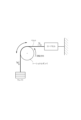
- the belt slip test was performed using a pulley rotation tester shown in FIG. 4 placed indoors. Specifically, as shown in Fig. 4, a torsional damper to be tested is placed between a load cell and a weight connected via a belt, and a belt is wound around the V-groove of the torsional damper. board.
- the load cell is fixed to a wall or the like, and the torsional damper is arranged so that the belt from the load cell to the torsional damper is generally horizontal, and the belt from the torsional damper to the weight is vertical.
- a torsional damper was set in such a pulley rotation tester, the torsional damper was first rotated at a rotation speed of 60 rpm, and the load of the load cell was measured when the rotation was stabilized. Next, the torsional damper was rotated at +20 rpm, and the load of the load cell was similarly measured. After that, the operation of rotating the torsional damper with the rotational speed of +20 rpm and measuring the load of the load cell was repeated until the rotational speed reached 260 rpm.
- the torsional damper of Comparative Example 1 has a friction coefficient of 0.97 when the sliding speed (m/s) is 1.0 m/s, and a sliding speed (m/s) of 1.5 m/s.
- the friction coefficient at s was 1.02. Therefore, belt squeal is likely to occur.
- the torsional damper of Example 1 has a friction coefficient of 0.80 when the sliding speed (m/s) is 1.0 m/s, and the sliding speed (m/s) is 1.5 m/s. /s, the coefficient of friction was 0.85. That is, the coefficient of friction was 18% and 17% lower than the comparative example. Therefore, it is considered that belt squeal is unlikely to occur.
Landscapes
- Engineering & Computer Science (AREA)
- General Engineering & Computer Science (AREA)
- Mechanical Engineering (AREA)
- Physics & Mathematics (AREA)
- Acoustics & Sound (AREA)
- Aviation & Aerospace Engineering (AREA)
- Pulleys (AREA)
- Paints Or Removers (AREA)
Abstract
Description
要因としては、エンジンの回転変動大、ベルトテンション変動等が挙げられるが、これらはいずれも自動車ライフ上、防ぐことは困難である。よって、他の要因によるベルト鳴きを抑える手法が望まれている。
このスティックスリップによる断続的なベルト鳴きを抑制するには、以下の方法が考えられる。
( i )ベルト滑りをしないようにする。
( ii )ベルトが滑ってもベルト鳴きしないようにする。
ここで自動車ライフの中で( i )を実現することは困難である。そこで、( ii )を検討するべきである。
(1)伝動ベルトを巻き付けて用いるトーショナルダンパであって、
前記伝動ベルトと接触するV溝部の表面に塗膜を有し、
前記塗膜の表面粗さRaが3.0以上であり、表面粗さRzが6.0以上である、トーショナルダンパ。
(2)前記塗膜は樹脂ビーズおよび/または潤滑ワックスを含み、
ベルトスリップ試験によって測定される、すべり速度(m/s)が1.0m/sのときの摩擦係数をAx、すべり速度(m/s)が1.5m/sのときの摩擦係数をBxとし、
前記塗膜が前記樹脂ビーズおよび前記潤滑ワックスを含まず、その他は全て同一である別のトーショナルダンパを用いたベルトスリップ試験によって測定される、すべり速度(m/s)が1.0m/sのときの摩擦係数をAy、すべり速度(m/s)が1.5m/sのときの摩擦係数をByとしたときに、
式(1)・・・(Ax-Ay)/Ay×100<-10
式(2)・・・(Bx-By)/By×100<-10
を満たす、上記(1)に記載のトーショナルダンパ。
(3)前記樹脂ビーズの粒径が10~40μmである、上記(1)または(2)に記載のトーショナルダンパ。
(4)前記塗膜における前記樹脂ビーズの含有率が10質量%以下である、上記(1)~(3)のいずれかに記載のトーショナルダンパ。
(5)前記塗膜における前記潤滑ワックスの含有率が10質量%以下である、上記(1)~(4)のいずれかに記載のトーショナルダンパ。
(6)伝動ベルトを巻き付けて用いるトーショナルダンパにおける前記伝動ベルトと接触するV溝部の表面に塗布して用いる塗料であって、
樹脂ビーズを10質量%以下の含有率で含有する、塗料。
(7)前記樹脂ビーズの粒径が10~40μmである、上記(6)に記載の塗料。
(8)前記樹脂ビーズがアクリル樹脂からなる、上記(7)に記載の塗料。
(9)さらに潤滑ワックスを10質量%以下の含有率で含有する、上記(6)~(8)のいずれかに記載の塗料。
(10)エポキシ樹脂の含有率が30~75質量%であり、
顔料の含有率が5~40質量%であり、
溶媒の含有率が5~40質量%である、上記(6)~(9)のいずれかに記載の塗料。
本発明は、伝動ベルトを巻き付けて用いるトーショナルダンパであって、前記伝動ベルトと接触するV溝部の表面に塗膜を有し、前記塗膜の表面粗さRaが3.0以上であり、表面粗さRzが6.0以上である、トーショナルダンパである。
このようなトーショナルダンパを、以下では「本発明のトーショナルダンパ」ともいう。
このような塗料を、以下では「本発明の塗料」ともいう。
図1は、本発明のトーショナルダンパの好適態様を例示した概略斜視図であり、図2は図1に示したトーショナルダンパの概略断面斜視図である。
トーショナルダンパ1はハブ3と、振動リング5と、ゴムリング7とを有する。
ボス部31は、ハブ3における径方向の中央部に設けられている。ボス部31がクランクシャフトの先端に締結され、ハブ3が中心軸Xを中心に回転駆動する。
ステー部33は、ボス部31から径方向に伸びている。
リム部35は、ステー部33の外周側に設けられている。リム部35は円筒状であり、リム部35の外周側にゴムリング7を介して振動リング5が連結される。
このようなV溝は切削加工等によって形成することができる。
伝動ベルトに形成されたリブがV溝に咬み込むことによって、走行時における伝動ベルトの幅方向の移動が規制される。
塗膜53は、その表面粗さRaが3.0以上であり、かつ、表面粗さRzが6.0以上のものである。
なお、本発明において塗膜の表面粗さRaはJIS B 0601 2001に基づいて測定して得た値を意味し、塗膜の表面粗さRzはJIS B 0601 2001に基づいて測定して得た値を意味するものとする。
塗膜の硬度は鉛筆硬度測定(JIS K 5600-5-4)で測定する。塗膜硬度の実力値は鉛筆硬度「H」であってよい。
樹脂ワックスとは、ポリエチレンからなるワックスである。クレヨン、キャンドル等に使用されている。
顔料として、例えば着色顔料、防錆顔料、体質顔料(タルク等)が挙げられる。
これに対して、塗膜が樹脂ビーズおよび潤滑ワックスの両方を含まず、それ以外の全て、すなわち樹脂ビーズおよび潤滑ワックスを含まないこと以外、その塗膜組成(組成の質量比)は同一であり、塗膜以外の形状、大きさ、材質等も全て同一であるが別のトーショナルダンパを用意し、これを用いて同様のベルトスリップ試験を行ったときに測定される、すべり速度(m/s)が1.0m/sのときの摩擦係数をAy、すべり速度(m/s)が1.5m/sのときの摩擦係数をByとする。
このような場合に、本発明のトーショナルは、次の式(1)および式(2)を満たすものであることが好ましい。
式(1)・・・(Ax-Ay)/Ay×100<-10
式(2)・・・(Bx-By)/By×100<-10
つまり、本発明のトーショナルダンパにおける塗膜が樹脂ビーズおよび/または潤滑ワックスを含む場合、それらを含まないトーショナルダンパと比較して、ベルスリップ試験を行ったときに測定される、1.0m/sまたは1.5m/sのすべり速度における摩擦係数が、いずれも10%以上低下するものであることが好ましい。
このような場合、そのような本発明のトーショナルは、ベルトが滑ったとしてもベルト鳴きが発生し難いからである。
ここで塗膜の厚さは一般的な電磁式膜厚計(接触式)で測定する。具体的には、V溝部の全体の外周にフィルムを巻き付けて、本発明の塗料を塗布して塗膜を形成した後、フィルムの膜厚を電磁式膜厚計を用いて円周複数箇所測定し、平均値に、フィルム面積/V溝部の面積を乗じた(面積換算)した値を塗膜の厚さとする。
なお、天然ゴム、天然ゴムとスチレン-ブタジエン共重合ゴムのブレンドゴム、ブタジエンゴム、天然ゴムとブタジエンゴムのブレンドゴム、スチレン-ブタジエン共重合ゴム、クロロプレンゴム、アクリロニトリル-ブタジエン共重合ゴム、水添化アクリロニトリル-ブタジエン共重合ゴム、エチレン-アクリレート共重合ゴム、フッ素ゴム、アクリルゴム等をゴム材料として、ゴム組成物を得ることもできる。
例えば従来公知のトーショナルダンパにおけるV溝部に、本発明の塗料を塗布することで製造することができる。
塗膜53をV溝部51の表面に形成する方法も特に限定されず、例えば従来公知の方法によって、塗膜53を形成することができる。例えばディピング、スプレーなどの方法によって塗膜53を少なくともV溝部51の表面に形成することができる。
本発明の塗料は、伝動ベルトを巻き付けて用いるトーショナルダンパにおける前記伝動ベルトと接触するV溝部の表面に塗布して用いる塗料である。つまり、図1および図2における塗膜53を形成するための塗料である。
本発明の塗料はエポキシ樹脂を30~75質量%含んでよい。
本発明の塗料における溶媒の含有率は5~40質量%であってよい。
実施例1に係る塗料は、エポキシ樹脂の含有率が45~75質量%であり、顔料の含有率が5~40質量%であり、溶媒の含有率が5~25質量%であり、粒径が10~40μmでありアクリル樹脂からなる樹脂ビーズの含有率が1~10質量%であり、潤滑ワックスの含有率が1~10質量%の組成物である。
実施例2に係る塗料は、エポキシ樹脂の含有率が30~45質量%であり、顔料の含有率が5~40質量%であり、溶媒の含有率が25~40質量%であり、粒径が10~40μmでありアクリル樹脂からなる樹脂ビーズの含有率が1~10質量%であり、潤滑ワックスの含有率が1~10質量%の組成物である。
比較例1に係る塗料は、樹脂ビーズと潤滑ワックスを含まず、それ以外は実施例1と同一の組成物である。
比較例2に係る塗料は、樹脂ビーズと潤滑ワックスを含まず、それ以外は実施例2と同一の組成物である。
その結果、実施例1に係るトーショナルダンパにおける塗膜の表面粗さRaは4.336、表面粗さRzは9.761であった。
これに対して、比較例1に係るトーショナルダンパにおける塗膜の表面粗さRaは1.800、表面粗さRzは4.764であった。
また、比較例1に係るトーショナルダンパにおける塗膜の表面粗さRaは3.0未満であり、表面粗さRzは6.0未満であった。
また、実施例1および比較例1のトーショナルダンパにおける塗膜の表面の粗さを3D粗さ計(カラーレーザー顕微鏡VK-9700/9710、(株)キーエンス社製)を用いて測定した。
マイクロスコープによる観察結果および3D粗さ計による測定結果を図3に示す。図3に示すように、実施例1における塗膜表面には樹脂ビーズに由来する凹凸が形成されていることが確認できた。これに対して、比較例1における塗膜表面には、そのような凹凸が形成されていなかった。また、比較例1に対して実施例1における塗膜表面が粗いことが確認できた。
具体的には以下のような試験を行い、実施例および比較例のトーショナルダンパの静・動摩擦係数を測定した。なお、動摩擦係数は6つのサンプルについて測定し、平均値を求めた。また、、静摩擦係数は4つのサンプルについて測定し、平均値を求めた。
結果を表1に示す。
摩擦係数測定試験機(佐川製作所)
ボール圧子φ20剛球 3点圧子 引張速度250mm/min
<静摩擦係数>
簡易式摩擦係数測定機
傾斜角度を徐々に上げていき、錘のすべり出し角度を測定して計算して求める。

ベルトスリップ試験について以下に説明する。
ベルトスリップ試験は、室内に載置された図4に示すプーリー回転試験機を用いて行った。具体的には、図4に示すように、ベルトを介して繋がれたロードセルとウェイトとの間に試験対象となるトーショナルダンパを配置し、トーショナルダンパのV溝部にベルトを巻き掛けて用いた。また、ロードセルは壁等に固定されており、ロードセルからトーショナルダンパまでの間のベルトは概ね水平方向、トーショナルダンパからウェイトまでのベルトは鉛直方向となるように、トーショナルダンパを配置した。
次に、回転数を+20rpmとしてトーショナルダンパを回転させ、同様にロードセルの荷重を測定した。
その後、同様に回転数をさらに+20rpmとしてトーショナルダンパを回転させてロードセルの荷重を測定する操作を、回転数が260rpmとなるまで繰り返した。
そして、得られた回転数と有効径とから、(回転数rpm/60)×(有効径mm/1000)×π)という式より、すべり速度(m/s)を求めた。なお、この実験で用いたトーショナルダンパの有効径(ポリV部有効径)は、146mmであった。
また、得られたロードセルの荷重とウェイト荷重とベルト巻き角とから、μ=1/θ×ln(Tt/Ts)の式より、摩擦係数(μ)を求めた。なお、ここでTt(単位:kgf)は回転数毎に読み取る荷重である。また、Ts(単位:kgf)はウェイトの重さであり、この実験では2kgfとした。
図5から、実施例のトーショナルダンパの方が、比較例のトーショナルダンパよりも摩擦係数が低いことが確認できる。
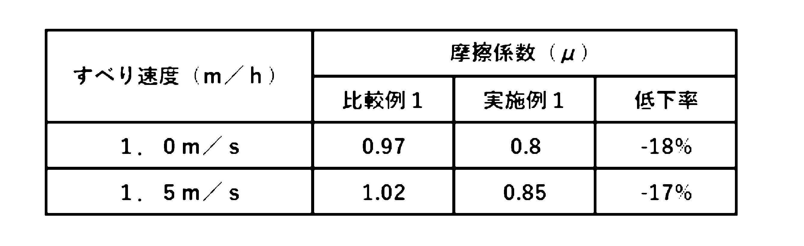
これに対して、実施例1のトーショナルダンパは、すべり速度(m/s)が1.0m/sのときの摩擦係数が0.80であり、すべり速度(m/s)が1.5m/sのときの摩擦係数が0.85であった。つまり、比較例に対して摩擦係数は18%および17%低くなった。
したがって、ベルト鳴きは発生し難いと考えられる。
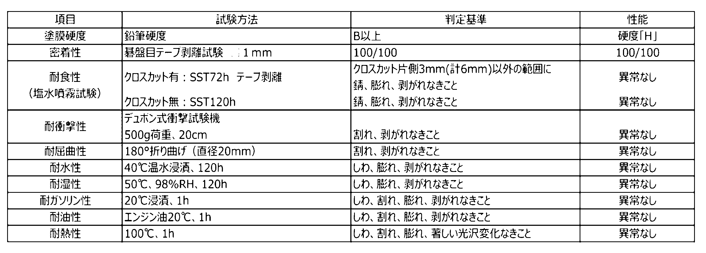
表3より、本発明に該当する実施例1および実施例2に係るトーショナルダンパは、基礎性能を備えることが確認できる。
3 ハブ
31 ボス部
33 ステー部
35 リム部
5 振動リング
51 プーリ溝
53 塗膜
7 ゴムリング
Claims (10)
- 伝動ベルトを巻き付けて用いるトーショナルダンパであって、
前記伝動ベルトと接触するV溝部の表面に塗膜を有し、
前記塗膜の表面粗さRaが3.0以上であり、表面粗さRzが6.0以上である、トーショナルダンパ。 - 前記塗膜は樹脂ビーズおよび/または潤滑ワックスを含み、
ベルトスリップ試験によって測定される、すべり速度(m/s)が1.0m/sのときの摩擦係数をAx、すべり速度(m/s)が1.5m/sのときの摩擦係数をBxとし、
前記塗膜が前記樹脂ビーズおよび前記潤滑ワックスを含まず、その他は全て同一である別のトーショナルダンパを用いたベルトスリップ試験によって測定される、すべり速度(m/s)が1.0m/sのときの摩擦係数をAy、すべり速度(m/s)が1.5m/sのときの摩擦係数をByとしたときに、
式(1)・・・(Ax-Ay)/Ay×100<-10
式(2)・・・(Bx-By)/By×100<-10
を満たす、請求項1に記載のトーショナルダンパ。 - 前記樹脂ビーズの粒径が10~40μmである、請求項1または2に記載のトーショナルダンパ。
- 前記塗膜における前記樹脂ビーズの含有率が10質量%以下である、請求項1または2に記載のトーショナルダンパ。
- 前記塗膜における前記潤滑ワックスの含有率が10質量%以下である、請求項1または2に記載のトーショナルダンパ。
- 伝動ベルトを巻き付けて用いるトーショナルダンパにおける前記伝動ベルトと接触するV溝部の表面に塗布して用いる塗料であって、
樹脂ビーズを10質量%以下の含有率で含有する、塗料。 - 前記樹脂ビーズの粒径が10~40μmである、請求項6に記載の塗料。
- 前記樹脂ビーズがアクリル樹脂からなる、請求項7に記載の塗料。
- さらに潤滑ワックスを10質量%以下の含有率で含有する、請求項6または7に記載の塗料。
- エポキシ樹脂の含有率が30~75質量%であり、
顔料の含有率が5~40質量%であり、
溶媒の含有率が5~40質量%である、請求項6または7に記載の塗料。
Priority Applications (2)
| Application Number | Priority Date | Filing Date | Title |
|---|---|---|---|
| CN202280033296.XA CN117280138A (zh) | 2021-07-26 | 2022-07-22 | 扭转减振器以及用于得到该扭转减振器的涂料 |
| JP2023538492A JP7550318B2 (ja) | 2021-07-26 | 2022-07-22 | トーショナルダンパおよびそれを得るために用いる塗料 |
Applications Claiming Priority (2)
| Application Number | Priority Date | Filing Date | Title |
|---|---|---|---|
| JP2021121385 | 2021-07-26 | ||
| JP2021-121385 | 2021-07-26 |
Publications (1)
| Publication Number | Publication Date |
|---|---|
| WO2023008331A1 true WO2023008331A1 (ja) | 2023-02-02 |
Family
ID=85086864
Family Applications (1)
| Application Number | Title | Priority Date | Filing Date |
|---|---|---|---|
| PCT/JP2022/028485 Ceased WO2023008331A1 (ja) | 2021-07-26 | 2022-07-22 | トーショナルダンパおよびそれを得るために用いる塗料 |
Country Status (3)
| Country | Link |
|---|---|
| JP (1) | JP7550318B2 (ja) |
| CN (1) | CN117280138A (ja) |
| WO (1) | WO2023008331A1 (ja) |
Citations (2)
| Publication number | Priority date | Publication date | Assignee | Title |
|---|---|---|---|---|
| US20020119851A1 (en) * | 2000-12-21 | 2002-08-29 | Wacker-Chemie Gmbh | Pulley with microprofiled surface |
| JP2004132457A (ja) * | 2002-10-10 | 2004-04-30 | Toyota Motor Corp | 摺動部材 |
-
2022
- 2022-07-22 JP JP2023538492A patent/JP7550318B2/ja active Active
- 2022-07-22 CN CN202280033296.XA patent/CN117280138A/zh active Pending
- 2022-07-22 WO PCT/JP2022/028485 patent/WO2023008331A1/ja not_active Ceased
Patent Citations (2)
| Publication number | Priority date | Publication date | Assignee | Title |
|---|---|---|---|---|
| US20020119851A1 (en) * | 2000-12-21 | 2002-08-29 | Wacker-Chemie Gmbh | Pulley with microprofiled surface |
| JP2004132457A (ja) * | 2002-10-10 | 2004-04-30 | Toyota Motor Corp | 摺動部材 |
Also Published As
| Publication number | Publication date |
|---|---|
| JPWO2023008331A1 (ja) | 2023-02-02 |
| JP7550318B2 (ja) | 2024-09-12 |
| CN117280138A (zh) | 2023-12-22 |
Similar Documents
| Publication | Publication Date | Title |
|---|---|---|
| US20100052262A1 (en) | Sealing device | |
| JP7120447B2 (ja) | 円すいころ軸受 | |
| JP6882067B2 (ja) | トーショナルダンパ | |
| JP2011102641A (ja) | 摩擦伝動ベルト及びその製造方法 | |
| WO2008062863A1 (en) | Piston ring | |
| MX2013015314A (es) | Junta de piston. | |
| JP5374425B2 (ja) | ベルト式変速装置 | |
| US7780556B2 (en) | Belt drive system | |
| JP2851225B2 (ja) | 摩擦用部材 | |
| JP7550318B2 (ja) | トーショナルダンパおよびそれを得るために用いる塗料 | |
| WO2015093463A1 (ja) | 摺動部材 | |
| JP7377696B2 (ja) | トーショナルダンパ | |
| JP5479658B1 (ja) | ピストンリング | |
| Makrahy et al. | Effect of compressibility of brake friction materials on vibration occurrence | |
| JP2025105954A (ja) | 摩擦伝動ベルト | |
| US20150276023A1 (en) | Power Transmission Belt With Thermoplastic Film Containing A Silicone Elastomer | |
| WO2021124821A1 (ja) | トーショナルダンパ | |
| JP4730168B2 (ja) | ラジアル転がり軸受の試験方法 | |
| JP2016205555A (ja) | 歯付ベルト | |
| JP7186772B2 (ja) | 摺動式スプライン軸装置 | |
| WO2021124818A1 (ja) | トーショナルダンパ | |
| EP4080085A1 (en) | Torsional damper | |
| JP7713840B2 (ja) | シール用ゴム組成物、及び密封部材 | |
| CN210178766U (zh) | 张紧轮用的密封滚动轴承 | |
| JP2004132457A (ja) | 摺動部材 |
Legal Events
| Date | Code | Title | Description |
|---|---|---|---|
| 121 | Ep: the epo has been informed by wipo that ep was designated in this application |
Ref document number: 22849393 Country of ref document: EP Kind code of ref document: A1 |
|
| WWE | Wipo information: entry into national phase |
Ref document number: 202280033296.X Country of ref document: CN |
|
| WWE | Wipo information: entry into national phase |
Ref document number: 2301007586 Country of ref document: TH |
|
| WWE | Wipo information: entry into national phase |
Ref document number: 2023538492 Country of ref document: JP |
|
| NENP | Non-entry into the national phase |
Ref country code: DE |
|
| 122 | Ep: pct application non-entry in european phase |
Ref document number: 22849393 Country of ref document: EP Kind code of ref document: A1 |