WO2023007633A1 - 制御方法、制御プログラム、ノード、およびシステム - Google Patents
制御方法、制御プログラム、ノード、およびシステム Download PDFInfo
- Publication number
- WO2023007633A1 WO2023007633A1 PCT/JP2021/027963 JP2021027963W WO2023007633A1 WO 2023007633 A1 WO2023007633 A1 WO 2023007633A1 JP 2021027963 W JP2021027963 W JP 2021027963W WO 2023007633 A1 WO2023007633 A1 WO 2023007633A1
- Authority
- WO
- WIPO (PCT)
- Prior art keywords
- logic
- cooperation
- partial
- node
- blockchain
- Prior art date
- Legal status (The legal status is an assumption and is not a legal conclusion. Google has not performed a legal analysis and makes no representation as to the accuracy of the status listed.)
- Ceased
Links
Images








Classifications
-
- G—PHYSICS
- G06—COMPUTING OR CALCULATING; COUNTING
- G06F—ELECTRIC DIGITAL DATA PROCESSING
- G06F21/00—Security arrangements for protecting computers, components thereof, programs or data against unauthorised activity
- G06F21/60—Protecting data
-
- G—PHYSICS
- G06—COMPUTING OR CALCULATING; COUNTING
- G06F—ELECTRIC DIGITAL DATA PROCESSING
- G06F21/00—Security arrangements for protecting computers, components thereof, programs or data against unauthorised activity
- G06F21/60—Protecting data
- G06F21/64—Protecting data integrity, e.g. using checksums, certificates or signatures
-
- G—PHYSICS
- G09—EDUCATION; CRYPTOGRAPHY; DISPLAY; ADVERTISING; SEALS
- G09C—CIPHERING OR DECIPHERING APPARATUS FOR CRYPTOGRAPHIC OR OTHER PURPOSES INVOLVING THE NEED FOR SECRECY
- G09C1/00—Apparatus or methods whereby a given sequence of signs, e.g. an intelligible text, is transformed into an unintelligible sequence of signs by transposing the signs or groups of signs or by replacing them by others according to a predetermined system
Definitions
- the present invention relates to control methods, control programs, nodes, and systems.
- the federated system executes a series of transactions by sequentially recording transaction information on multiple blockchain networks so as to exchange multiple assets managed by different blockchain networks upon request. do.
- the contents of the transaction information may change depending on, for example, input values.
- a first transaction is generated in which a user and a counterparty deposit virtual currency, and a second transaction distributes the deposited virtual currency according to a spot rate using a public key obtained from a neutral party.
- a first secret key share corresponding to a first possible outcome of the condition set and a second secret key share corresponding to a second possible outcome of the condition set are generated using a secret sharing protocol.
- JP 2019-212241 A Japanese Patent Publication No. 2020-534734 U.S. Patent Application Publication No. 2020/0058018
- the present invention aims to appropriately record transaction information on a blockchain network.
- the node forming the block chain network encrypts the information included in at least one of the first partial logic groups forming the target logic to generate the second Acquiring a partial logic group, recording the acquired second partial logic group in a blockchain managed by the blockchain network, and assigning the second partial logic group recorded in the blockchain to the node.
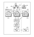
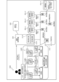
- FIG. 1 is an explanatory diagram of an example of a control method according to an embodiment.
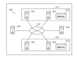
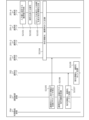
- FIG. 2 is an explanatory diagram showing an example of the BC cooperation system 200.
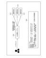
- FIG. 3 is an explanatory diagram showing an application example of the BC cooperation system 200.
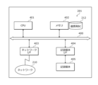
- FIG. 4 is a block diagram showing a hardware configuration example of the cooperation node 201.
- FIG. 5 is an explanatory diagram showing an example of the contents stored in the encrypted fragment management table 500.
- FIG. FIG. 6 is an explanatory diagram showing an example of the contents stored in the correspondence information management table 600.
- FIG. 7 is a block diagram showing a hardware configuration example of the cooperation destination node 202. As shown in FIG. FIG. FIG.
- FIG. 8 is a block diagram showing a hardware configuration example of the cooperative control device 203.
- FIG. 9 is a block diagram showing a hardware configuration example of the user-side device 204.
- FIG. 10 is a block diagram showing an example of the functional configuration of the BC cooperation system 200.
- FIG. 11 is a block diagram showing a specific example of the functional configuration of the BC cooperation system 200.
- FIG. 12 is an explanatory diagram (Part 1) showing an operation example of the BC cooperation system 200.
- FIG. 13 is an explanatory diagram (part 2) showing an operation example of the BC cooperation system 200.
- FIG. FIG. 14 is an explanatory diagram (part 3) showing an operation example of the BC cooperation system 200.
- FIG. 15 is an explanatory diagram (part 4) showing an operation example of the BC cooperation system 200.
- FIG. 16 is an explanatory diagram (No. 5) showing an operation example of the BC cooperation system 200.
- FIG. 17 is an explanatory diagram (No. 6) showing an operation example of the BC cooperation system 200.
- FIG. 18 is an explanatory diagram (No. 7) showing an operation example of the BC cooperation system 200.
- FIG. 19 is a sequence diagram (Part 1) showing an example of the overall processing procedure.
- FIG. 20 is a sequence diagram (part 2) showing an example of the overall processing procedure.
- FIG. 21 is a sequence diagram (part 3) showing an example of the overall processing procedure.
- FIG. 1 is an explanatory diagram of an example of a control method according to an embodiment.
- the cooperation node 100 is a computer that forms a blockchain network.
- blockchain may be referred to as “BC (BlockChain)”.
- the BC network is a management system that manages BC.
- a BC network is formed by one or more nodes.
- the BC is managed by each node included in the BC network storing and monitoring the same BC.
- BC is a list that serves as a distributed ledger that manages transaction information by linking blocks in which transaction information is recorded. Examples of BC networks include public, consortium, and private BC networks.
- the cooperation node 100 specifically forms a cooperation BC network 101 .
- the cooperation node 100 is used when realizing a cooperation system that cooperates with a plurality of cooperation destination BC networks.
- the cooperation BC network 101 manages, for example, the cooperation BC 102 .
- the collaborating BC network manages, for example, collaborating BCs.
- a conventional collaboration system sequentially records transaction information in a plurality of linked BC networks so that multiple assets managed by different linked BC networks can be exchanged in response to a request. execute a transaction;
- the contents of the transaction information may change depending on, for example, input values.
- a future observation value may become an input value in one of the transactions.
- the future observed value related to the actual event becomes the input value in one of the transactions, and the transaction information whose content changes according to the future observed value related to the actual event is recorded in the partner BC.
- Observed values are, for example, room temperature, humidity, or power status.
- the conventional cooperative system has a problem that it is not possible to generate transaction information in advance for a transaction whose input value is an observed value until the observed value is determined. For this reason, in the conventional cooperation system, when a request is received, a signature cannot be added to the transaction information, and the transaction information cannot be recorded in the cooperation destination BC.
- a cooperation system including a cache server that does not generate transaction information until the observed value is confirmed, generates transaction information after the observed value is confirmed, and records it in the cooperation destination BC is conceivable.
- logic for generating transaction information based on observed values is stored in the cache server. At this time, it is desired to guarantee that the logic stored in the cache server is not altered, and there is a problem that the cache server becomes a trust point. As a result, the BC network's advantage of being able to guarantee the reliability of information without the presence of a central authority is lost.
- a cooperation system is conceivable in which transaction information is generated and recorded in the partner BC after the observed value is determined by a smart contract that includes logic to generate transaction information based on the observed value.
- this cooperation system there is a problem that the content of the logic included in the smart contract is leaked to a third party.
- the user may wish to keep the contents of the logic confidential.
- the user does not have to keep the results of stock trading confidential from third parties, but the logic that shows the strategy that indicates the basis of stock trading is , know-how, it may be desired to keep it confidential from a third party.
- control method that can record transaction information in a BC network so that the logic for executing a series of transactions is not leaked will be described. Also, according to the control method, it is possible to dispense with providing a trust point.
- the collaboration node 100 forms a BC network 101 for collaboration.
- the cooperation BC network 101 manages, for example, the cooperation BC 102 .
- three cooperation nodes 100 each store a cooperation BC 102 .
- target logic 103 that executes a series of transactions.
- the first partial logic group 110 is a set of first partial logics 111 .
- the first partial logic group 110 is generated by dividing the target logic 103, for example.
- the cooperation node 100 acquires the second partial logic group 120 .
- the second partial logic group 120 is a set of second partial logics 121 .
- the second logic portion 121 is, for example, the first logic portion 111 that is entirely plaintext or the first logic portion 111 that is at least partially encrypted. At least one of the second partial logics 121 of the second partial logic group 120 is preferably the first partial logic 111 at least partially encrypted.
- the plurality of second partial logics 121 are assigned to different cooperation nodes 100, for example.
- the second partial logic group 120 is generated by encrypting information contained in at least one of the first partial logic groups 111 of the first partial logic group 110 .
- the second logic part group 120 encrypts the information contained in the remaining first logic part 111 without encrypting the information contained in the part of the first logic part 111 of the first logic part 110 .
- Generated by encryption is composed of a part of the first partial logic 111 in which the entirety of the first partial logic group 110 is plaintext, and a remaining portion of the first partial logic in which part of the information is encrypted.
- 1 part logic 111 is included as a second part logic 121 .
- the second partial logic group 120 may be generated by, for example, encrypting information contained in each first partial logic 111 included in the first partial logic group 110 .
- the second partial logic group 120 includes, as the second partial logic 121, the respective first partial logics 111 of the first partial logic group 110 whose information is partially encrypted.
- the cooperation node 100 acquires, for example, the second partial logic group 120 by receiving it from another computer.
- the cooperation node 100 records the obtained second partial logic group 120 in the cooperation BC 102 managed by the cooperation BC network 101 .
- the cooperation node 100 forms a consensus among the plurality of cooperation nodes 100 regarding the acquired second logic part group 120, and records the acquired second logic part group 120 in the cooperation BC 102 stored in its own node. and shared by a plurality of cooperation nodes 100 .
- the cooperation node 100 acquires one of the second partial logics 121 assigned to itself from the second partial logic group 120 recorded in the cooperation BC 102 .
- the cooperation node 100 identifies the first partial logic 111 corresponding to the acquired second partial logic 121 in the first partial logic group 110 based on the acquired second partial logic 121 .
- the cooperation node 100 decrypts the information to obtain the first partial logic 111 corresponding to the obtained second partial logic 121. generated and identified. For example, if the acquired second partial logic 121 does not contain encrypted information, the cooperation node 100 directly converts the acquired second partial logic 121 into the first partial logic 121 corresponding to the acquired second partial logic 121 . It is identified as partial logic 111 .
- the linking node 100 When receiving an input value corresponding to the specified first partial logic 111, the linking node 100 outputs the result 130 of executing the specified first partial logic 111 based on the accepted input value. Record in the BC 102 for use. For example, the cooperation node 100 forms a consensus among the plurality of cooperation nodes 100 regarding the result 130 of executing the specified first logic part 111 . Then, the cooperation node 100 records, for example, the result 130 of executing the specified first partial logic 111 in the cooperation BC 102 stored therein, and shares it among the plurality of cooperation nodes 100 .
- the cooperation node 100 can record the result 130 of executing the first partial logic 111 in the cooperation BC 102 while reducing the risk of the target logic 103 being leaked.
- information included in at least one of the first partial logics 111 is encrypted, so that the risk of leakage of the target logic 103 can be reduced.
- a cooperation BC network 101 formed by one or more cooperation nodes 100 can be applied to a cooperation system.
- the BC network 101 for cooperation can refer to the BC 102 for cooperation, for example, and can record the result of having performed a series of transactions in BC for cooperation, and can form a cooperation system.
- the cooperation BC network 101 can guarantee that the target logic 103 will not be modified by the cooperation BC 102 without preparing a specific trust point.
- FIG. 2 is an explanatory diagram showing an example of the BC cooperation system 200.
- the BC cooperation system 200 includes a cooperation node 201 , a cooperation destination node 202 , a cooperation control device 203 and a user side device 204 .
- the cooperation nodes 201 when distinguishing between the cooperation nodes 201, they may be denoted as "cooperation nodes 201-i" by adding "-i" to the end of the reference numeral.
- i is a natural number.
- the cooperation node 201 and the cooperation control device 203 are connected via a wired or wireless network 210.
- the network 210 is, for example, a LAN (Local Area Network), a WAN (Wide Area Network), the Internet, or the like.
- the cooperation destination node 202 and the cooperation control device 203 are connected via a wired or wireless network 210 .
- the cooperative control device 203 and the user side device 204 are connected via a wired or wireless network 210 .
- a cooperation node 201 is a computer that forms a cooperation BC network 210 that manages a cooperation BC 212 .
- the cooperation node 201 receives a request to execute a series of transactions from the cooperation control device 203 .
- the request includes, for example, an encrypted fragment obtained by encrypting each fragment of multiple fragments forming the target logic.
- the request may include an encrypted fragment management table 500, described later in FIG. 5, in which a plurality of encrypted fragments are recorded.
- the request includes, for example, correspondence information that associates each encrypted fragment of a plurality of encrypted fragments with the cooperation node 201 to which the encrypted fragment is assigned.
- the request may include a correspondence information management table 600 described later in FIG. 6 in which correspondence information is recorded.
- the cooperation node 201 decrypts the encrypted fragment assigned to its own node and generates the original fragment of the encrypted fragment.
- the cooperation node 201 executes the logic indicated by the generated fragment and generates transaction information indicating the result of executing the logic.
- the cooperation node 201 forms a consensus among the plurality of cooperation nodes 201 regarding the transaction information indicating the result of executing the logic, and records the transaction information indicating the result of executing the logic in the cooperation BC 212 stored in the own node. do.
- the cooperation node 201 is, for example, a server or a PC (Personal Computer).
- a cooperation destination node 202 is a computer that forms a cooperation destination BC network 221 that manages a cooperation destination BC 222 .
- a plurality of cooperation destination BC networks 221 may exist.
- the cooperation destination node 202 receives transaction information indicating the result of executing the logic from the cooperation control device 203 .
- the cooperation destination node 202 forms a consensus among a plurality of cooperation destination nodes 202 regarding the transaction information indicating the result of executing the logic, and records the transaction information indicating the result of executing the logic in the cooperation destination BC 222 stored in the own node. do.
- the cooperation destination node 202 is, for example, a server or a PC.
- the cooperation control device 203 is a computer that monitors the cooperation BC 212.
- the cooperation control device 203 receives the request from the user device 204 .
- the request includes, for example, encrypted fragments.
- the request may include an encrypted fragment management table 500, which will be described later with reference to FIG.
- the request includes, for example, correspondence information.
- the request may include a correspondence information management table 600, which will be described later with reference to FIG.
- the cooperation control device 203 transmits the received request to the cooperation node 201 .
- the cooperation control device 203 detects that the transaction information indicating the result of executing the logic indicated by the specific fragment among the plurality of fragments has been recorded in the cooperation BC 212 .
- the cooperation control device 203 reads the transaction information indicating the result of executing the logic indicated by the specific fragment from the cooperation BC 212 and transmits it to the cooperation destination node 202 .
- the cooperation control device 203 is, for example, a server or a PC.
- the user-side device 204 generates a request based on the user's operation input.
- the request includes, for example, encrypted fragments.
- the request may include an encrypted fragment management table 500, which will be described later with reference to FIG.
- the request includes, for example, correspondence information.
- the request may include a correspondence information management table 600, which will be described later with reference to FIG.
- the user-side device 204 transmits the request to the cooperative control device 203 .
- the user-side device 204 is, for example, a PC, a tablet terminal, or a smart phone.
- the cooperation control device 203 may have the function of the cooperation node 201 and operate as the cooperation node 201 .
- the cooperation control device 203 and the user side device 204 are different devices.
- the present invention is not limited to this.
- the cooperative control device 203 may have the function of the user device 204 and operate as the user device 204 . In this case, the cooperative control system does not need to include the user-side device 204 .
- FIG. 3 is an explanatory diagram showing an application example of the BC cooperation system 200.
- the BC cooperation system 200 is applied to a service that executes a series of transactions related to remittance.
- subject logic for executing a series of transactions may include logic 300, for example.
- Logic 300 determines the remittance amount x based on the stock price, power value, and number of users after three days. Therefore, the remittance amount x may not be determined at the time of the request.
- the BC collaboration system 200 can reduce the risk of leakage of target logic for this service.
- the BC cooperation system 200 can appropriately execute a series of transactions regarding this service, and can appropriately record transaction information in the cooperation destination BC 222 .
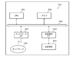
- FIG. 4 is a block diagram showing a hardware configuration example of the cooperation node 201.
- the cooperation node 201 has a CPU (Central Processing Unit) 401 , a memory 402 , a network I/F (Interface) 403 , a recording medium I/F 404 and a recording medium 405 . Also, each component is connected by a bus 400 .
- CPU Central Processing Unit
- memory 402
- network I/F Interface
- recording medium I/F 404 and a recording medium 405 .
- each component is connected by a bus 400 .
- the CPU 401 controls the entire cooperation node 201 .
- the memory 402 has, for example, a ROM (Read Only Memory), a RAM (Random Access Memory), a flash ROM, and the like. Specifically, for example, a flash ROM or ROM stores various programs, and a RAM is used as a work area for the CPU 401 .
- the program stored in the memory 402 causes the CPU 401 to execute coded processing by being loaded into the CPU 401 .
- the memory 402 stores the BC 212 for cooperation.
- the memory 402 stores an encrypted fragment management table 500, which will be described later with reference to FIG. 5, and a corresponding information management table 600, which will be described later with reference to FIG.
- the network I/F 403 is connected to the network 210 through a communication line, and is connected to other computers via the network 210.
- a network I/F 403 serves as an internal interface with the network 210 and controls input/output of data from other computers.
- Network I/F 403 is, for example, a modem or a LAN adapter.
- the recording medium I/F 404 controls reading/writing of data from/to the recording medium 405 under the control of the CPU 401 .
- the recording medium I/F 404 is, for example, a disk drive, SSD (Solid State Drive), USB (Universal Serial Bus) port, or the like.
- a recording medium 405 is a nonvolatile memory that stores data written under the control of the recording medium I/F 404 .
- the recording medium 405 is, for example, a disk, a semiconductor memory, a USB memory, or the like.
- the recording medium 405 may be removable from the cooperation node 201 .
- the cooperation node 201 may have, for example, a keyboard, mouse, display, printer, scanner, microphone, speaker, etc., in addition to the components described above. Also, the cooperation node 201 may have a plurality of recording medium I/Fs 404 and recording media 405 . Also, the cooperation node 201 may not have the recording medium I/F 404 and the recording medium 405 .
- the encrypted fragment management table 500 is realized, for example, by a storage area such as the memory 402 or recording medium 405 of the cooperation node 201 shown in FIG.
- FIG. 5 is an explanatory diagram showing an example of the content stored in the encrypted fragment management table 500.
- the encrypted fragment management table 500 has fields of process ID, type, process, next process ID, and belonging fragment ID.
- the encrypted fragment management table 500 stores processing information as a record 500-a by setting information in each field for each processing. a is any integer.
- a process ID that identifies a process included in the target logic is set in the process ID field.
- the type field the type of processing is set.
- the contents of the encrypted processing are set in the processing field.
- a process ID for identifying a process to be executed next to the above process is set in the next process ID field.
- the belonging fragment ID field an belonging fragment ID for identifying an encrypted fragment containing the content of the encrypted processing is set.
- the belonging fragment ID may be, for example, identification information commonly used for the encrypted fragment and the original fragment of the encrypted fragment.
- the correspondence information management table 600 is realized, for example, by a storage area such as the memory 402 or the recording medium 405 of the cooperation node 201 shown in FIG.
- FIG. 6 is an explanatory diagram showing an example of the contents stored in the correspondence information management table 600.
- the correspondence information management table 600 has fields of fragment ID, node, and public key.
- the correspondence information management table 600 stores correspondence information as a record 600-b by setting information in each field for each fragment. b is any integer.
- a fragment ID that identifies an encrypted fragment is set in the fragment ID field.
- the node field is set with a name that identifies a node having a public key that has encrypted the encrypted fragment.
- a public key obtained by encrypting the encrypted fragment is set in the public key field.
- the fragment ID may be, for example, identification information commonly used for the encrypted fragment and the original fragment of the encrypted fragment.
- FIG. 7 is a block diagram showing a hardware configuration example of the cooperation destination node 202.
- cooperation destination node 202 has CPU 701 , memory 702 , network I/F 703 , recording medium I/F 704 , and recording medium 705 . Also, each component is connected by a bus 700 .
- the CPU 701 controls the entire cooperation destination node 202 .
- the memory 702 has, for example, ROM, RAM and flash ROM. Specifically, for example, a flash ROM or ROM stores various programs, and a RAM is used as a work area for the CPU 701 .
- a program stored in the memory 702 causes the CPU 701 to execute coded processing by being loaded into the CPU 701 .
- the memory 702 stores the cooperation destination BC 222 .
- the network I/F 703 is connected to the network 210 through a communication line, and is connected to other computers via the network 210.
- a network I/F 703 serves as an internal interface with the network 210 and controls input/output of data from other computers.
- Network I/F 703 is, for example, a modem or a LAN adapter.
- the recording medium I/F 704 controls reading/writing of data from/to the recording medium 705 under the control of the CPU 701 .
- a recording medium I/F 704 is, for example, a disk drive, an SSD, a USB port, or the like.
- a recording medium 705 is a nonvolatile memory that stores data written under control of the recording medium I/F 704 .
- the recording medium 705 is, for example, a disk, semiconductor memory, USB memory, or the like.
- the recording medium 705 may be removable from the cooperation destination node 202 .
- the cooperation destination node 202 may have, for example, a keyboard, mouse, display, printer, scanner, microphone, speaker, etc., in addition to the components described above. Also, the cooperation destination node 202 may have a plurality of recording medium I/Fs 704 and recording media 705 . Also, the cooperation destination node 202 may not have the recording medium I/F 704 and the recording medium 705 .
- FIG. 8 is a block diagram showing a hardware configuration example of the cooperative control device 203.
- the cooperative control device 203 has a CPU 801 , a memory 802 , a network I/F 803 , a recording medium I/F 804 and a recording medium 805 . Also, each component is connected by a bus 800 .
- the CPU 801 controls the overall control of the cooperative control device 203 .
- the memory 802 has, for example, ROM, RAM and flash ROM. Specifically, for example, a flash ROM or ROM stores various programs, and a RAM is used as a work area for the CPU 801 .
- a program stored in the memory 802 causes the CPU 801 to execute coded processing by being loaded into the CPU 801 .
- the memory 802 stores the encrypted fragment management table 500 shown in FIG. 5, the correspondence information management table 600 shown in FIG. 6, and the like.
- the network I/F 803 is connected to the network 210 through a communication line, and is connected to other computers via the network 210.
- a network I/F 803 serves as an internal interface with the network 210 and controls input/output of data from other computers.
- a network I/F 803 is, for example, a modem or a LAN adapter.
- a recording medium I/F 804 controls reading/writing of data from/to the recording medium 805 under the control of the CPU 801 .
- a recording medium I/F 804 is, for example, a disk drive, an SSD, a USB port, or the like.
- a recording medium 805 is a non-volatile memory that stores data written under the control of the recording medium I/F 804 .
- the recording medium 805 is, for example, a disk, a semiconductor memory, a USB memory, or the like.
- the recording medium 805 may be removable from the cooperative control device 203 .
- the cooperation control device 203 may have, for example, a keyboard, mouse, display, printer, scanner, microphone, speaker, etc., in addition to the components described above. Also, the cooperation control device 203 may have a plurality of recording medium I/Fs 804 and recording media 805 . Also, the cooperative control device 203 may not have the recording medium I/F 804 and the recording medium 805 .
- FIG. 9 is a block diagram showing a hardware configuration example of the user-side device 204.
- the user side device 204 has a CPU 901 , a memory 902 , a network I/F 903 , a recording medium I/F 904 , a recording medium 905 , a display 906 and an input device 907 . Also, each component is connected by a bus 900 .
- the CPU 901 controls the entire user-side device 204 .
- the memory 902 has, for example, ROM, RAM and flash ROM. Specifically, for example, a flash ROM or ROM stores various programs, and a RAM is used as a work area for the CPU 901 .
- a program stored in the memory 902 causes the CPU 901 to execute coded processing by being loaded into the CPU 901 .
- the network I/F 903 is connected to the network 210 through a communication line, and is connected to other computers via the network 210.
- a network I/F 903 serves as an internal interface with the network 210 and controls input/output of data from other computers.
- Network I/F 903 is, for example, a modem or a LAN adapter.
- a recording medium I/F 904 controls reading/writing of data from/to the recording medium 905 under the control of the CPU 901 .
- a recording medium I/F 904 is, for example, a disk drive, an SSD, a USB port, or the like.
- a recording medium 905 is a non-volatile memory that stores data written under the control of the recording medium I/F 904 .
- the recording medium 905 is, for example, a disk, semiconductor memory, USB memory, or the like.
- the recording medium 905 may be removable from the user-side device 204 .
- a display 906 displays data such as documents, images, function information, as well as cursors, icons or toolboxes.
- the display 906 is, for example, a CRT (Cathode Ray Tube), a liquid crystal display, an organic EL (Electroluminescence) display, or the like.
- the input device 907 has keys for inputting characters, numbers, various instructions, etc., and inputs data.
- the input device 907 may be a keyboard, a mouse, or the like, or may be a touch panel type input pad or numeric keypad.
- the user-side device 204 may have, for example, a printer, a scanner, a microphone, a speaker, etc., in addition to the components described above. Also, the user-side device 204 may have a plurality of recording medium I/Fs 904 and recording media 905 . Also, the user-side device 204 may not have the recording medium I/F 904 and the recording medium 905 .
- FIG. 10 is a block diagram showing an example of the functional configuration of the BC cooperation system 200.
- the cooperation control device 203 includes a first storage section 1010 , a first acquisition section 1011 , a monitoring section 1012 and a first output section 1013 .
- the first storage unit 1010 is implemented, for example, by a storage area such as the memory 802 or recording medium 805 shown in FIG. A case where the first storage unit 1010 is included in the cooperation control device 203 will be described below, but the present invention is not limited to this.
- the first storage unit 1010 may be included in a device different from the cooperative control device 203 , and the contents stored in the first storage unit 1010 may be referenced from the cooperative control device 203 .
- the first acquisition unit 1011 to first output unit 1013 function as an example of a control unit. Specifically, for example, the first acquisition unit 1011 to the first output unit 1013 cause the CPU 801 to execute a program stored in a storage area such as the memory 802 or the recording medium 805 shown in FIG. 8, or The network I/F 803 implements that function. The processing result of each functional unit is stored in a storage area such as the memory 802 or recording medium 805 shown in FIG. 8, for example.
- the first storage unit 1010 stores various information that is referred to or updated in the processing of each functional unit.
- the first storage unit 1010 stores the second partial logic group.
- the second partial logic group is a set of second partial logics.
- the second portion of logic is the first portion of logic that remains entirely in plaintext, or the first portion of logic in which at least part of the information is encrypted.
- the second part logic is, for example, the encryption fragment mentioned above.
- Information to be encrypted is, for example, information including a variable to which an input value is set or a conditional expression to which an input value is set.
- the second partial logic group is generated by encrypting information included in at least one of the first partial logic groups.
- the second partial logic group uses the public key of the cooperation node 201 to which the first partial logic is assigned to the information contained in at least one of the first partial logics of the first partial logic group. Generated by encryption.
- the second partial logic group may include, as the second partial logic, the first partial logic in which the information is not encrypted among the first partial logic groups.
- the second partial logic group may be generated, for example, by encrypting information included in each first partial logic included in the first partial logic group.
- the second logic part group may be generated by encrypting information included in each first logic logic part with the public key of the cooperation node 201 to which the first logic logic part is assigned. good.
- the first partial logic group is a set of first partial logics.
- the first partial logic is, for example, logic forming the target logic.
- the first part logic is specifically the fragment mentioned above.
- the first partial logic group is generated by dividing the target logic based on a conditional expression included in the target logic.
- the first storage unit 1010 stores an encrypted fragment management table 500 that enables identification of a plurality of encrypted fragments.
- the second partial logic group is acquired by the first acquisition unit 1011 and stored by the first storage unit 1010, for example.
- the first storage unit 1010 stores correspondence information that associates the second partial logic corresponding to the first partial logic with the cooperation node 201 to which the second partial logic is assigned. Since the cooperation node 201 is associated with the second partial logic, it is indirectly associated with the first partial logic.
- First storage unit 1010 specifically stores correspondence information management table 600 . The correspondence information is acquired by the first acquisition unit 1011 and stored by the first storage unit 1010, for example.
- the first acquisition unit 1011 acquires various information used for processing of each functional unit.
- the first acquisition unit 1011 stores the acquired various information in the first storage unit 1010 or outputs the acquired information to each functional unit. Further, the first acquisition unit 1011 may output various information stored in the first storage unit 1010 to each functional unit.
- the first acquisition unit 1011 acquires various types of information, for example, based on a user's operation input.
- the first acquisition unit 1011 may receive various types of information from a device other than the cooperative control device 203, for example.
- the first acquisition unit 1011 acquires the second partial logic group.
- the first acquisition unit 1011 acquires, for example, the second partial logic group by receiving it from another computer.
- the other computer is, for example, the user-side device 204 .
- the first acquisition unit 1011 may acquire the second partial logic group by, for example, receiving an input of the second partial logic group based on the user's operation input.
- the first acquisition unit 1011 receives a request including the encrypted fragment management table 500 from another computer.
- the first acquisition unit 1011 acquires correspondence information.
- the first acquisition unit 1011 acquires correspondence information by receiving it from another computer, for example.
- the other computer is, for example, the user-side device 204 .
- the first acquisition unit 1011 may acquire correspondence information by, for example, accepting input of correspondence information based on user's operation input. Specifically, the first acquisition unit 1011 receives a request including the correspondence information management table 600 from another computer.
- the first acquisition unit 1011 may accept a start trigger for starting processing of any of the functional units.
- the start trigger is, for example, that there is a predetermined operation input by the user.
- the start trigger may be, for example, reception of predetermined information from another computer.
- the start trigger may be, for example, the output of predetermined information by any of the functional units.
- the first acquisition unit 1011 receives acquisition of the second partial logic group and the correspondence information as a start trigger for starting the processing of the monitoring unit 1012 and the first output unit 1013 .
- the monitoring unit 1012 monitors the BC 212 for cooperation. For example, the monitoring unit 1012 monitors the BC 212 for cooperation after transmitting the second partial logic group from the first output unit 1013 .
- the monitoring unit 1012 detects that the result of executing at least a specific first partial logic out of the first partial logic group is recorded in the cooperation BC 212 as a result of monitoring, the monitoring unit 1012 executes the specific first partial logic.
- the result obtained is acquired from the BC 212 for cooperation.
- the specific first partial logic is, for example, the first partial logic whose execution order is the last in the first partial logic group.
- the specific first partial logic may be, for example, the first partial logic including output processing.
- the specific first part logic is specifically a first part logic including output processing for transmitting transaction information to the cooperation destination BC 222 and causing the cooperation destination BC 222 to record the transaction information.
- the monitoring unit 1012 can acquire the result of executing the specific first partial logic, which corresponds to the final result of executing the target logic, when the execution of the target logic is completed.
- the monitoring unit 1012 can acquire the result of executing the specific first part logic corresponding to the transaction information to be recorded in the cooperation destination BC 222 when the transaction information to be recorded in the cooperation destination BC 222 is generated. .
- the first output unit 1013 outputs the processing result of at least one of the functional units.
- the output format is, for example, display on a display, print output to a printer, transmission to an external device via the network I/F 803, or storage in a storage area such as the memory 802 or recording medium 805. This enables the first output unit 1013 to notify the user of the processing result of at least one of the functional units, thereby improving the convenience of the cooperative control device 203 .
- the first output unit 1013 transmits the second partial logic group to each cooperation node 201 .
- the first output unit 1013 for example, transmits a request including the second partial logic group to each of the cooperation nodes 201 .
- the first output unit 1013 can enable each of the cooperation nodes 201 to refer to the second partial logic group, and outputs the first partial logic corresponding to the second partial logic assigned to the own node. can be made executable.
- the first output unit 1013 transmits to the cooperation destination node 202 as transaction information to be recorded in the cooperation destination BC 222 the result of executing the acquired specific first part logic. Thereby, the first output unit 1013 can record the result of executing the specific first partial logic in the cooperation destination BC 222 . Therefore, the first output unit 1013 can leave a trail of execution of a series of transactions in the cooperation destination BC 222 .
- the cooperation node 201 includes a second storage unit 1020, a second acquisition unit 1021, an identification unit 1022, a management unit 1023, and a second output unit 1024. include.
- the cooperation node 201 forms, for example, a cooperation BC network 210 .
- the second storage unit 1020 is implemented, for example, by a storage area such as the memory 402 or recording medium 405 shown in FIG. Although a case where the second storage unit 1020 is included in the cooperation node 201 will be described below, the present invention is not limited to this.
- the second storage unit 1020 may be included in a device different from the cooperation node 201 , and the contents stored in the second storage unit 1020 may be referenced from the cooperation node 201 .
- the second acquisition unit 1021 to second output unit 1024 function as an example of a control unit. Specifically, for example, the second acquisition unit 1021 to the second output unit 1024 cause the CPU 401 to execute a program stored in a storage area such as the memory 402 or the recording medium 405 shown in FIG. 4, or The network I/F 403 implements that function. The processing result of each functional unit is stored in a storage area such as the memory 402 or recording medium 405 shown in FIG. 4, for example.
- the second storage unit 1020 stores various information that is referred to or updated in the processing of each functional unit.
- the second storage unit 1020 stores the BC 212 for cooperation.
- the cooperation BC 212 records the second partial logic group.
- the cooperation BC 212 specifically records an encrypted fragment management table 500 that enables identification of a plurality of encrypted fragments.
- the cooperation BC 212 stores transaction information. Transaction information indicates the result of executing the first part logic.
- the second partial logic group is acquired by the second acquisition unit 1021 and stored by the second storage unit 1020, for example.
- the transaction information is generated by the management unit 1023 and stored by the second storage unit 1020, for example.
- the second storage unit 1020 stores correspondence information that associates the second partial logic corresponding to the first partial logic with the cooperation node 201 to which the second partial logic is assigned.
- Second storage unit 1020 specifically stores correspondence information management table 600 .
- the correspondence information is acquired by the second acquisition unit 1021 and stored by the second storage unit 1020, for example.
- the correspondence information may be stored by the cooperation BC 212 stored in the second storage unit 1020 .
- the second acquisition unit 1021 acquires various information used for processing of each functional unit.
- the second acquisition unit 1021 stores the acquired various information in the second storage unit 1020 or outputs the acquired information to each functional unit. Further, the second acquisition unit 1021 may output various information stored in the second storage unit 1020 to each functional unit.
- the second acquisition unit 1021 acquires various information, for example, based on the user's operation input.
- the second acquisition unit 1021 may receive various information from a device different from the cooperation node 201, for example.
- the second acquisition unit 1021 acquires the second partial logic group.
- the second acquisition unit 1021 acquires, for example, the second partial logic group by receiving it from another computer.
- Another computer is, for example, the cooperative control device 203 .
- Second acquisition unit 1021 specifically receives a request including encrypted fragment management table 500 from another computer.
- the second acquisition unit 1021 records the acquired second partial logic group in the cooperation BC 212 . Thereby, the second acquiring unit 1021 can store the second partial logic group in a state that is difficult to falsify.
- the second acquisition unit 1021 acquires correspondence information.
- the second acquisition unit 1021 acquires correspondence information by receiving it from another computer, for example.
- Another computer is, for example, the cooperative control device 203 .
- second acquisition unit 1021 receives a request including correspondence information management table 600 from another computer.
- the second acquisition unit 1021 acquires an input value corresponding to the first partial logic.
- the input value may become observable, for example, after the second logic subgroup is recorded in the BC 212 for cooperation.
- the second acquisition unit 1021 acquires, for example, an input value corresponding to the first partial logic corresponding to any second partial logic assigned to the own node.
- the second acquisition unit 1021 executes another first partial logic that has been executed before the first partial logic corresponding to the second partial logic assigned to the own node, which is recorded in the cooperation BC 212.
- the second acquisition unit 1021 may acquire an input value from another computer or a sensor that acquires an observed value as an input value. This allows the second acquisition unit 1021 to execute the first partial logic.
- the second acquisition unit 1021 may accept a start trigger to start processing of any functional unit.
- the start trigger is, for example, that there is a predetermined operation input by the user.
- the start trigger may be, for example, reception of predetermined information from another computer.
- the start trigger may be, for example, the output of predetermined information by any of the functional units.
- the second acquisition unit 1021 receives, for example, acquisition of the second partial logic group as a start trigger for starting the processing of the identification unit 1022 .
- the second acquisition unit 1021 receives, for example, acquisition of an input value corresponding to the first logic part as a start trigger for starting the processing of the management unit 1023 .
- the specifying unit 1022 specifies the first partial logic corresponding to any of the second partial logics assigned to the own node among the second partial logic groups recorded in the cooperation BC 212 .
- the identifying unit 1022 identifies, for example, the first partial logic corresponding to the second partial logic assigned to the own node, among the first partial logic groups, based on the second partial logic assigned to the own node.
- the identifying unit 1022 refers to the correspondence information to identify the second partial logic assigned to the own node. If encrypted information is included in the identified second logic portion, the identification unit 1022 decrypts the encrypted information using the private key corresponding to the own node, thereby obtaining the identified second logic logic portion. generates a first portion of logic corresponding to If the identified second logic portion does not contain encrypted information, the identifying unit 1022 directly adopts the identified second logic logic portion as the first logic logic portion corresponding to the second logic logic portion. Thereby, the identifying unit 1022 can identify the first partial logic to be executed.
- the management unit 1023 executes the specified first logic part based on the accepted input value.
- the management unit 1023 records the result of executing the identified first partial logic in the cooperation BC 212 .
- the management unit 1023 can refer to the execution result of the identified first partial logic recorded in the cooperation BC 212 when executing another first partial logic.
- the management unit 1023 can allow the cooperation control device 203 to refer to the execution result of the identified first partial logic recorded in the cooperation BC 212 . Therefore, the management unit 1023 can cause the cooperation destination BC 222 to record the result of executing the identified first partial logic via the cooperation control device 203 .
- the management unit 1023 may encrypt the result of executing the identified first partial logic and record it in the cooperation BC 212. Specifically, the management unit 1023 acquires the public key of the other cooperation node 201 to which the second partial logic corresponding to the first partial logic to be executed next to the identified first partial logic is assigned. good too. Specifically, the management unit 1023 may encrypt the result of executing the specified first logic part with the acquired public key and record it in the cooperation BC 212 . Thereby, the management unit 1023 can easily conceal the result of executing the specified first partial logic. Therefore, the management unit 1023 can easily conceal the content of the specified first partial logic.
- the management unit 1023 may add a signature using the signature key of the cooperation node 201 to the result of executing the specified first logic part and record it in the cooperation BC 212 .
- a signature key is, for example, a private key corresponding to a public key. As a result, the management unit 1023 can improve the reliability of the result of executing the specified first logic part.
- the second output unit 1024 outputs the processing result of at least one of the functional units.
- the output format is, for example, display on a display, print output to a printer, transmission to an external device via the network I/F 403, or storage in a storage area such as the memory 402 or recording medium 405.
- the second output unit 1024 can notify the user of the processing result of at least one of the functional units, thereby improving the convenience of the cooperation node 201 .
- the collaboration destination node 202 includes a third storage unit 1030, a third acquisition unit 1031, a recording unit 1032, and a third output unit 1033.
- the cooperation destination node 202 forms, for example, a cooperation destination BC network 221 .
- the third storage unit 1030 is realized, for example, by a storage area such as the memory 702 and recording medium 705 shown in FIG. Although the case where the third storage unit 1030 is included in the cooperation destination node 202 will be described below, the present invention is not limited to this.
- the third storage unit 1030 may be included in a device different from the cooperation destination node 202 , and the contents stored in the third storage unit 1030 may be referenced from the cooperation destination node 202 .
- the third acquisition unit 1031 to third output unit 1033 function as an example of a control unit. Specifically, for example, the third acquisition unit 1031 to the third output unit 1033 cause the CPU 701 to execute a program stored in a storage area such as the memory 702 or the recording medium 705 shown in FIG. 7, or The network I/F 703 implements that function. The processing result of each functional unit is stored in a storage area such as the memory 702 or the recording medium 705 shown in FIG. 7, for example.
- the third storage unit 1030 stores various information referred to or updated in the processing of each functional unit.
- Third storage unit 1030 stores cooperation destination BC 222 .
- the cooperation destination BC 222 records the result of executing the first part logic.
- the result of executing the first logic part is acquired by the third acquisition unit 1031 and stored by the third storage unit 1030, for example.
- the third acquisition unit 1031 acquires various types of information used for processing of each functional unit.
- the third acquisition unit 1031 stores the acquired various information in the third storage unit 1030 or outputs it to each functional unit. Further, the third acquisition unit 1031 may output various information stored in the third storage unit 1030 to each functional unit.
- the third acquisition unit 1031 acquires various types of information, for example, based on user's operation input.
- the third acquisition unit 1031 may receive various types of information from a device different from the cooperation destination node 202, for example.
- the third acquisition unit 1031 acquires the result of executing the first part logic.
- the third acquisition unit 1031 acquires, for example, the result of executing the first part logic by receiving it from the cooperation control device 203 .
- the recording unit 1032 records the result of executing the first part logic in the cooperation destination BC 222.
- the recording unit 1032 forms a consensus among the plurality of cooperation destination nodes 202 regarding the result of executing the first logic part, and records the result of executing the first logic logic part in the cooperation destination BC 222 . Thereby, the recording unit 1032 can leave a trail of execution of a series of transactions.
- a third output unit 1033 outputs the processing result of at least one of the functional units.
- the output format is, for example, display on a display, print output to a printer, transmission to an external device via the network I/F 703, or storage in a storage area such as the memory 702 or recording medium 705.
- the third output unit 1033 can notify the user of the processing result of at least one of the functional units, thereby improving the convenience of the cooperation destination node 202 .
- FIG. 11 is a block diagram showing a specific example of the functional configuration of the BC cooperation system 200.
- the user-side device 204 includes a key requesting unit 1101, a logic creating unit 1102, a graphing unit 1103, an encryption unit 1104, and a transaction requesting unit 1105. include.
- the key request unit 1101 transmits a public key acquisition request to the cooperation control device 203.
- the public key acquisition request indicates that a public key corresponding to each cooperation node 201 forming the cooperation BC network 211 is requested.
- the key request unit 1101 receives the public key corresponding to each cooperation node 201 from the cooperation control device 203 .
- the logic creation unit 1102 creates target logic for executing a series of transactions based on the user's operation input.
- the graphing unit 1103 graphs the target logic.
- the graphing unit 1103 graphs the target logic by, for example, treating each instruction included in the target logic as a node and expressing transitions between instructions as edges.
- the graphing unit 1103 outputs the graph of the target logic so that the user can refer to it.
- the encryption unit 1104 assigns the N fragments to different cooperation nodes 201 based on the user's operation input. The encryption unit 1104 generates an encrypted fragment corresponding to each of the N fragments by encrypting each fragment with the public key corresponding to the cooperation node 201 to which the fragment is assigned.
- the encryption unit 1104 generates an encrypted fragment management table 500 that records encrypted fragments.
- the encryption unit 1104 generates a correspondence information management table 600 that records correspondence information that associates the public key of each cooperation node 201 with the encrypted fragment encrypted with the public key.
- Transaction request unit 1105 generates a transaction execution request including encrypted fragment management table 500 and correspondence information management table 600 , and transmits it to cooperation control device 203 .
- a trade execution request requests to execute a series of trades.
- the cooperation control device 203 includes a key issuing unit 1111, a transaction issuing unit 1112, a transaction initiation unit 1113, a signature issuing unit 1114, and a transaction monitoring unit 1115.
- the key issuing unit 1111 receives a public key acquisition request from the user-side device 204 .
- the key issuing unit 1111 transmits the public key corresponding to each cooperation node 201 to the user-side device 204 in response to the public key acquisition request.
- the transaction issuing unit 1112 receives the signed transaction information from the signature issuing unit 1114 .
- the transaction issuing unit 1112 transmits the signed transaction information to each cooperation destination node 202 forming the cooperation destination BC network 221 .
- the transaction initiation unit 1113 receives a transaction execution request.
- the transaction initiation unit 1113 transmits the received transaction execution request to each cooperation node 201 .
- Signature issuer 1114 receives transaction information from transaction monitor 1115 .
- the signature issuing unit 1114 adds a signature using a signature key corresponding to the cooperation control device 203 to the received transaction information.
- the signature issuing unit 1114 transmits the signed transaction information to the transaction issuing unit 1112 .
- the transaction monitoring unit 1115 monitors the cooperation BC 212 after transmitting the transaction execution request to each cooperation node 201 .
- the transaction monitoring unit 1115 When the transaction monitoring unit 1115 detects that the transaction information indicating the result of executing the specific fragment is recorded in the cooperation BC 212, the transaction monitoring unit 1115 reads the transaction information indicating the result of executing the specific fragment from the cooperation BC 212. Transaction monitoring unit 1115 transmits the read transaction information to signature issuing unit 1114 .
- the cooperation node 201 includes key information 1121, a logic calculation unit 1122, and a transaction issuing unit 1123.
- Key information 1121 includes a public key and a private key.
- Logic calculation unit 1122 receives the transaction execution request and extracts encrypted fragment management table 500 and correspondence information management table 600 . Based on the encrypted fragment management table 500 and the correspondence information management table 600, the logic calculation unit 1122 decrypts the encrypted fragment associated with the node, thereby generating the fragment assigned to the node. .
- the transaction issuing unit 1123 acquires input values related to the logic indicated by the generated fragments.
- the transaction issuing unit 1123 reads, for example, an input value related to the logic indicated by the generated fragment from the cooperation BC 212 .
- the transaction issuing unit 1123 receives, for example, an input value related to the logic indicated by the generated fragment from another computer, or a sensor that acquires an observed value as an input value.
- the transaction issuing unit 1123 executes the logic indicated by the generated fragment based on the acquired input value.
- the transaction issuing unit 1123 generates transaction information indicating the result of executing the logic indicated by the generated fragment, and transmits the transaction information to each cooperation destination node 202 .
- the cooperation destination node 202 receives the signed transaction information from the cooperation control device 203 .
- the cooperation destination node 202 records the signed transaction information in the cooperation destination BC 222 .
- 2 ⁇ N ⁇ the number of cooperation nodes 201 and two or more fragments may be assigned to the same cooperation node 201 .
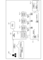
- FIG. 12 to 18 are explanatory diagrams showing operation examples of the BC cooperation system 200.
- the cooperation node 201-1 stores key information 1 including public key 1 and private key 1.
- the cooperation node 201-2 stores key information 2 including a public key 2 and a private key 2.
- the cooperation node 201-3 stores key information 3 including a public key 3 and a private key 3.
- the cooperation node 201-4 stores the key information 4 including the public key 4 and the private key 4.
- FIG. 12 to 18 are explanatory diagrams showing operation examples of the BC cooperation system 200.
- FIG. 12 to 18, the cooperation node 201-1 stores key information 1 including public key 1 and private key 1.
- the cooperation node 201-2 stores key information 2 including a public key 2 and a private key 2.
- the cooperation node 201-3 stores key information 3 including a public key 3 and a private key 3.
- the cooperation node 201-4 stores the key information 4 including the public key 4 and the private key 4.
- the cooperation BC 212 stores the verification smart contract 1 corresponding to the cooperation node 201-1.
- the verification smart contract 1 executes the logic indicated by the fragment assigned to the cooperation node 201-1, and transfers the transaction information indicating the result of executing the logic indicated by the fragment assigned to the cooperation node 201-1 to the cooperation node 201-1. It has a function of recording in the BC 212 for use.
- the cooperation BC 212 stores the verification smart contract 2 corresponding to the cooperation node 201-2.
- the verification smart contract 2 executes the logic indicated by the fragment assigned to the cooperation node 201-2, and transfers the transaction information indicating the result of executing the logic indicated by the fragment assigned to the cooperation node 201-2 to the cooperation node 201-2. It has a function of recording in the BC 212 for use.
- the cooperation BC 212 stores the verification smart contract 3 corresponding to the cooperation node 201-3.
- the verification smart contract 3 executes the logic indicated by the fragment assigned to the cooperation node 201-3, and transfers the transaction information indicating the result of executing the logic indicated by the fragment assigned to the cooperation node 201-3 to the cooperation node 201-3. It has a function of recording in the BC 212 for use.
- the cooperation BC 212 stores the output verification smart contract corresponding to the cooperation node 201-4.
- the output verification smart contract executes the logic indicated by the fragment assigned to the cooperation node 201-4, and transfers the transaction information indicating the result of executing the logic indicated by the fragment assigned to the cooperation node 201-4 to the cooperation node 201-4. It has a function of recording in the BC 212 for use.
- the BC 212 for cooperation stores the logic storage smart contract.
- the logic storage smart contract has a function of recording the encrypted fragment management table 500 in the cooperation BC 212 .
- the smart contract may be referred to as "SC (Smart Contract)". Next, the description of FIG. 12 will be described.
- the user-side device 204 transmits a public key acquisition request to the cooperation control device 203 based on the user's operation input.
- the public key acquisition request indicates that a public key corresponding to each cooperation node 201 forming the cooperation BC network 211 is requested.
- the user-side device 204 receives the public key corresponding to each cooperation node 201 from the cooperation control device 203 .
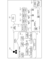
- FIG. 13 the description of FIG. 13 will be described.
- the user-side device 204 generates target logic 1300 for executing a series of transactions based on the user's operation input.
- the target logic 1300 includes variables for which future observed values are set as input values, or conditional expressions for which future observed values are set as input values.
- the user-side device 204 among the target logic 1300, based on a variable for which a future observed value is set as an input value or a conditional expression for which a future observed value is set as an input value, Graph the target logic 1300 to generate a graph 1400 .
- the user-side device 204 graphs the target logic 1300 by, for example, treating each instruction included in the target logic 1300 as a node and expressing transitions between instructions as edges.
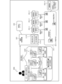
- FIG. 15 will be described.
- the user-side device 204 divides the target logic 1300 into fragment 1, fragment 2, fragment 3, and output fragment based on the user's operation input.
- the user-side device 204 allocates the fragment 1 to the cooperation node 201-1, the fragment 2 to the cooperation node 201-2, and the fragment 3 to the cooperation node 201-3 based on the user's operation input.
- the output fragment is assigned to the cooperation node 201-4.
- the user-side device 204 encrypts the information contained in the fragment 1 with the public key 1 corresponding to the cooperation node 201-1 to which the fragment 1 is assigned, and generates the encrypted fragment 1.
- the user-side device 204 encrypts the information included in the fragment 2 with the public key 2 corresponding to the cooperation node 201-2 to which the fragment 2 is assigned, and generates the encrypted fragment 2.
- the user-side device 204 encrypts the information included in the fragment 3 with the public key 3 corresponding to the cooperation node 201-3 to which the fragment 3 is assigned, and generates the encrypted fragment 3.
- FIG. The user-side device 204 encrypts the information contained in the output fragment with the public key 4 corresponding to the cooperation node 201-4 to which the output fragment is assigned to generate the encrypted output fragment.
- the user-side device 204 generates an encrypted fragment management table 500 that records encrypted fragment 1, encrypted fragment 2, encrypted fragment 3, and encrypted output fragment.
- the user-side device 204 associates the name of each cooperation node 201, the public key corresponding to the cooperation node 201, and the encrypted fragment obtained from the fragment assigned to the cooperation node 201.
- a correspondence information management table 600 in which the correspondence information is recorded is generated.
- the user-side device 204 generates a transaction execution request including the encrypted fragment management table 500 and the corresponding information management table 600 and transmits it to the cooperative control device 203 .
- the cooperative control device 203 receives a transaction execution request from the user device 204 .
- the cooperation control device 203 transmits a transaction execution request to each cooperation node 201 forming the cooperation BC network 210 .
- the cooperation control device 203 causes the transaction monitoring unit 1115 to start monitoring the cooperation BC 212 .
- the cooperation control device 203 starts monitoring that the transaction information indicating the result of executing the logic indicated by the output fragment is recorded in the cooperation BC 212 by the transaction monitoring unit 1115 .
- Each cooperation node 201 saves the encrypted fragment management table 500 and correspondence information management table 600 in the cooperation BC 212 by the logic storage SC. Next, the description of FIG. 17 will be described.
- the cooperation node 201-1 identifies the encrypted fragment 1 corresponding to its own node based on the encrypted fragment management table 500 and the correspondence information management table 600 by the verification SC1.
- the cooperation node 201-1 decrypts the encrypted fragment 1 corresponding to its own node with the secret key 1 corresponding to its own node by the verification SC1, thereby generating the fragment 1 assigned to its own node.
- the cooperation node 201-1 When the cooperation node 201-1 detects that the input value included in the logic indicated by the generated fragment 1 has been determined, it acquires the input value.
- the cooperation node 201-1 receives an input value from, for example, another computer or a sensor that acquires an observed value as an input value.
- the cooperation node 201-1 may detect that the input value is recorded in the cooperation BC 212 and read the input value from the cooperation BC 212.
- the cooperation node 201-1 executes the logic indicated by the generated fragment 1 based on the acquired input value, and records the transaction information indicating the result of executing the logic indicated by the generated fragment 1 in the cooperation BC 212. .
- the transaction information indicates, for example, whether the if (confidential) determination is Yes or No.
- the cooperation node 201-1 may acquire the public key of another cooperation node 201 to which the fragment 2 or fragment 3 to be executed next to the fragment 1 assigned to the own node is assigned.
- the cooperation node 201-1 may encrypt the transaction information indicating the result of executing the logic indicated by the generated fragment 1 with the obtained public key, and then record it in the cooperation BC 212.
- Other cooperation nodes 201 are specified based on the correspondence information management table 600, for example.
- the signature key is private key 1, for example.
- the cooperation node 201-2 identifies the encrypted fragment 2 corresponding to its own node based on the encrypted fragment management table 500 and the correspondence information management table 600 by the verification SC2.
- the cooperation node 201-2 decrypts the encrypted fragment 2 corresponding to its own node with the private key 2 corresponding to its own node by the verification SC 2, thereby generating the fragment 2 assigned to its own node.
- the cooperation node 201-2 When the cooperation node 201-2 detects that the input value included in the logic indicated by the generated fragment 2 has been determined, it acquires the input value.
- the cooperation node 201-2 receives an input value from, for example, another computer, or a sensor that acquires an observed value as an input value.
- the cooperation node 201-2 may detect that the input value is recorded in the cooperation BC 212 and read the input value from the cooperation BC 212.
- FIG. Specifically, the cooperation node 201-2 detects that transaction information indicating that if (confidential) determination Yes, which can be decrypted with the private key of its own node, is recorded in the cooperation BC 212. You may Then, the cooperation node 201-2 may read the detected transaction information as an input value.
- the cooperation node 201-2 executes the logic indicated by the generated fragment 2 based on the acquired input value, and records the transaction information indicating the result of executing the logic indicated by the generated fragment 2 in the cooperation BC 212. .
- the transaction information indicates, for example, the processing result of the command (confidentiality).
- the cooperation node 201-2 may, for example, acquire the public key of another cooperation node 201 to which an output fragment to be executed subsequent to fragment 2 assigned to its own node is assigned.
- the cooperation node 201-2 may, for example, encrypt the transaction information indicating the result of executing the logic indicated by the generated fragment 2 with the obtained public key, and then record it in the cooperation BC 212.
- Other cooperation nodes 201 are specified based on the correspondence information management table 600, for example.
- the cooperation node 201-2 encrypts the transaction information with the public key of the other cooperation node 201-4 to which the output fragment to be executed next to the fragment 2 assigned to its own node is assigned.
- the cooperation node 201-2 may add a signature using the signature key corresponding to the own node to the transaction information indicating the result of executing the logic indicated by the generated fragment 2.
- the signature key is private key 2, for example.
- the cooperation node 201-3 identifies the encrypted fragment 3 corresponding to its own node based on the encrypted fragment management table 500 and the correspondence information management table 600 by the verification SC3.
- the cooperation node 201-3 decrypts the encrypted fragment 3 corresponding to its own node with the private key 3 corresponding to its own node by the verification SC 3, thereby generating the fragment 3 assigned to its own node.
- the cooperation node 201-3 When the cooperation node 201-3 detects that the input value included in the logic indicated by the generated fragment 3 has been determined, it acquires the input value.
- the cooperation node 201-3 receives an input value from, for example, another computer or a sensor that acquires an observed value as an input value.
- the cooperation node 201-3 may detect that the input value is recorded in the cooperation BC 212 and read the input value from the cooperation BC 212.
- FIG. Specifically, the cooperation node 201-3 detects that the transaction information that can be decrypted with the private key of the node itself and indicates that if (secret) determination No is recorded in the cooperation BC 212. You may Then, the cooperation node 201-3 may read the detected transaction information as an input value.
- the cooperation node 201-3 executes the logic indicated by the generated fragment 3 based on the acquired input value, and records the transaction information indicating the result of executing the logic indicated by the generated fragment 3 in the cooperation BC 212.
- the transaction information indicates, for example, the processing result of the command (confidentiality).
- the cooperation node 201-3 may acquire the public key of another cooperation node 201 to which an output fragment to be executed subsequent to fragment 3 assigned to its own node is assigned.
- the cooperation node 201-3 may encrypt the transaction information indicating the result of executing the logic indicated by the generated fragment 3 with the obtained public key, and then record it in the cooperation BC 212.
- Other cooperation nodes 201 are specified based on the correspondence information management table 600, for example.
- the cooperation node 201-3 encrypts the transaction information with the public key of the other cooperation node 201-4 to which the output fragment to be executed next to the fragment 3 assigned to its own node is assigned.
- the cooperation node 201-3 may add a signature using the signature key corresponding to the own node to the transaction information indicating the result of executing the logic indicated by the generated fragment 3.
- the signature key is private key 3, for example.
- the cooperation node 201-4 identifies the encrypted output fragment corresponding to its own node based on the encrypted fragment management table 500 and the correspondence information management table 600 by the output verification SC.
- the cooperation node 201-4 generates an output fragment assigned to its own node by decrypting the encrypted output fragment corresponding to its own node using the output verification SC with the secret key 4 corresponding to its own node. .
- the cooperation node 201-4 When the cooperation node 201-4 detects that the input value included in the logic indicated by the generated output fragment has been determined, it acquires the input value.
- the cooperation node 201-4 detects that the input value is recorded in the cooperation BC 212, and reads the input value from the cooperation BC 212.
- the cooperation node 201-4 may detect that the transaction information indicating the processing result of the command (confidential) that can be decrypted with the private key of the own node is recorded in the cooperation BC 212. . Then, the cooperation node 201-4 may read the detected transaction information as an input value.
- the cooperation node 201-4 executes the logic indicated by the generated output fragment based on the acquired input value, and records the transaction information indicating the result of executing the logic indicated by the generated output fragment in the cooperation BC 212. .
- the transaction information indicates, for example, output (confidential) processing results.
- the cooperation node 201-4 may add a signature using the signature key corresponding to the own node to the transaction information indicating the result of executing the logic indicated by the generated output fragment.
- the signature key is private key 4, for example.
- the cooperation control device 203 detects that the transaction monitoring unit 1115 has recorded the transaction information indicating the result of executing the logic indicated by the output fragment in the cooperation BC 212 .
- the cooperation control device 203 uses the transaction monitoring unit 1115 to acquire transaction information indicating the result of executing the logic indicated by the output fragment from the cooperation BC 212 .
- the cooperative control device 203 uses the signature issuing unit 1114 to add a signature using a signature key corresponding to its own device to the acquired transaction information.
- the cooperation control device 203 transmits the signed transaction information to each cooperation destination node 202 .
- the cooperation control device 203 may transmit the hash value of the signed transaction information to each cooperation destination node 202 as new transaction information.
- Each cooperation destination node 202 receives the signed transaction information.
- Each cooperation destination node 202 records the signed transaction information in the cooperation destination BC 222 .
- the BC cooperation system 200 can prevent the target logic 1300 from being stored in a plaintext state, and can reduce the risk of the target logic 1300 being leaked.
- the BC cooperation system 200 since the BC cooperation system 200 records the target logic 1300 in the cooperation BC 212, it is possible to prevent the target logic 1300 from being tampered with. Therefore, the BC cooperation system 200 can be realized without including a trust point.
- the BC cooperation system 200 appropriately records the transaction information related to the target logic 1300 in the cooperation destination BC 222 even if the input value is undetermined at the time of the transaction execution request while reducing the risk of the target logic 1300 being leaked. can be made possible.
- FIG. 19 to 21 are sequence diagrams showing an example of the overall processing procedure.
- the user-side device 204 transmits a request requesting a public key to the cooperation control device 203 based on the user's operation input, and transmits the public key corresponding to each cooperation node 201 to the cooperation control device. It is received from the device 203 (step S1901).
- the user-side device 204 acquires target logic for executing a series of transactions based on the user's operation input (step S1902). Then, the user-side device 204 generates a graph representing the target logic and displays it on the display so that the user can refer to it (step S1903).
- the user-side device 204 divides the target logic into a plurality of fragments based on the user's operation input, and associates the plurality of fragments with different cooperation nodes 201 (step S1904). Then, the user-side device 204 encrypts each fragment with the public key corresponding to the cooperation node 201 corresponding to the fragment, acquires the encrypted fragment, and associates the fragment with the cooperation node 201 corresponding to the fragment. (Step S1905).
- the user-side device 204 sends a transaction request including the acquired plurality of encrypted fragments and correspondence information that enables identification of the cooperation node 201 corresponding to each encrypted fragment to the cooperation control device 203. It transmits (step S1906).
- the cooperation control device 203 Upon receiving the transaction request, the cooperation control device 203 transmits the received transaction request to each of the cooperation nodes 201 (step S1907). Next, the cooperation control device 203 starts monitoring the cooperation BC 212 (step S1908). Next, the description of FIG. 20 will be described.
- each of the cooperation nodes 201 extracts an encrypted fragment corresponding to its own node (step S2001).
- the cooperation node 201-1 detects that the observed value to be set as the input value has been found (step S2002). Next, the cooperation node 201-1 decrypts the extracted encrypted fragment and generates a fragment corresponding to the encrypted fragment (step S2003).
- the linking node 201-1 executes the logic indicated by the generated fragment, generates the transaction information representing the result of executing the logic indicated by the fragment, and generates the transaction information indicating the result of executing the logic indicated by the fragment, and the other linking node 201-1 corresponding to the next executed fragment. is encrypted with the public key of (step S2004). Further, the cooperation node 201-1 records the encrypted transaction information in the cooperation BC 212 and shares it with the plurality of cooperation nodes 201 (step S2005).
- the cooperation node 201-2 detects that the observed value to be set as the input value has been found (step S2006). Next, the cooperation node 201-2 decrypts the extracted encrypted fragment and generates a fragment corresponding to the encrypted fragment (step S2007).
- the linking node 201-2 executes the logic indicated by the generated fragment, generates transaction information representing the result of executing the logic indicated by the fragment, and generates the transaction information indicating the result of executing the logic indicated by the fragment, and the other linking node 201-2 corresponding to the next executed fragment. is encrypted with the public key of (step S2008). Furthermore, the cooperation node 201-2 records the encrypted transaction information in the cooperation BC 212 and shares it with the plurality of cooperation nodes 201 (step S2009).
- the cooperation node 201-3 detects that the observed value to be set as the input value has been found (step S2010). Next, the cooperation node 201-3 decrypts the extracted encrypted fragment and generates a fragment corresponding to the encrypted fragment (step S2011).
- the linking node 201-3 executes the logic indicated by the generated fragment, generates the transaction information representing the result of executing the logic indicated by the fragment, and generates the transaction information indicating the result of executing the logic indicated by the fragment. is encrypted with the public key of (step S2012). Furthermore, the cooperation node 201-3 records the encrypted transaction information in the cooperation BC 212 and shares it with the plurality of cooperation nodes 201 (step S2013). Next, the description of FIG. 21 will be described.
- the cooperation node 201-4 detects that the observed value to be set as the input value has been found (step S2101). Next, the cooperation node 201-4 decrypts the extracted encrypted fragment and generates a fragment corresponding to the encrypted fragment (step S2102).
- the linking node 201-4 executes the logic indicated by the generated fragment, generates transaction information representing the result of executing the logic indicated by the fragment, and generates the transaction information representing the result of executing the logic indicated by the fragment, and the other linking node 201-4 corresponding to the fragment to be executed next. is encrypted with the public key of (step S2103). Furthermore, the cooperation node 201-4 records the encrypted transaction information in the cooperation BC 212 and shares it with the plurality of cooperation nodes 201 (step S2104).
- the cooperation control device 203 detects that transaction information has been recorded in the cooperation BC 212 (step S2105). Next, the cooperation control device 203 acquires the transaction information recorded in the cooperation BC 212, and attaches a corresponding signature to its own device (step S2106). The cooperation control device 203 then transmits the signed transaction information to the cooperation destination node 202 (step S2107).
- Each cooperation destination node 202 records the signed transaction information in the cooperation destination BC 222 and shares it among the plurality of cooperation destination nodes 202 (step S2108). Then, the BC cooperation system 200 ends the overall processing. Thereby, the BC cooperation system 200 can execute a series of transactions while concealing the target logic.
- each cooperation node 201 executes the logic indicated by the generated fragment and generates transaction information representing the result of executing the logic indicated by the fragment, but the present invention is not limited to this.
- one of the cooperation nodes 201 does not execute the logic indicated by the generated fragment and does not generate the transaction information representing the result of executing the logic indicated by the fragment.
- the cooperation BC network 210 can be formed. According to the cooperation node 201, it is possible to obtain the second logic logic part group obtained by encrypting the information included in at least one of the logic logic logic logic parts of the first logic logic logic part forming the target logic. . According to the cooperation node 201 , the obtained second partial logic group can be recorded in the cooperation BC 212 managed by the cooperation BC network 210 . According to the cooperation node 201, based on one of the second partial logics assigned to the cooperation node 201 among the second partial logic group recorded in the cooperation BC 212, the first Partial logic can be specified.
- the cooperation node 201 when an input value corresponding to the specified first logic part is accepted, the result of executing the specified first logic part based on the accepted input value is recorded in the cooperation BC 212. can be done. As a result, the cooperation node 201 can make the result of executing the first partial logic available to other computers while keeping the target logic confidential.
- the cooperation node 201 According to the cooperation node 201, the information included in at least one of the first partial logics of the first partial logic group is encrypted with the public key of the cooperation node 201 to which the first partial logic is assigned. A second partial logic group can be obtained. As a result, the cooperation node 201 can easily conceal the target logic.
- the cooperation node 201 when an input value corresponding to the specified first partial logic is received, based on the accepted input value, the result of executing the specified first partial logic is encrypted and sent to the cooperation BC 212. can be recorded. Thereby, the cooperation node 201 can easily conceal the result of executing the first partial logic.
- the result of executing the specified first partial logic is transferred to another cooperation node to which the second partial logic corresponding to the first partial logic to be executed next to the specified first partial logic is assigned.
- the cooperation node 201 can easily conceal the result of executing the first logic part while remaining available for other cooperation nodes 201 .
- the result of executing the specified first partial logic can be signed by the signature key of the cooperation node 201 and recorded in the cooperation BC 212.
- the cooperation node 201 can improve the reliability of the result of executing the specified first logic part.
- a partial logic group can be acquired.
- the cooperation node 201 can easily conceal the target logic.
- the cooperation node 201 it is possible to acquire the first partial logic group generated by dividing the target logic based on the conditional expression included in the target logic. Thereby, the cooperation node 201 can acquire the first partial logic group obtained by appropriately dividing the target logic.
- the cooperation node 201 it is possible to accept an input value corresponding to the identified first partial logic observable after the second partial logic group is recorded in the cooperation BC 212. As a result, the cooperation node 201 can be applied to situations in which input values are determined ex post facto.
- the result of executing the identified first partial logic can be recorded in the cooperation destination BC 222 via the cooperation monitoring device that monitors the cooperation BC 212.
- the cooperation node 201 can appropriately leave a trace of execution of the target logic.
- the cooperation node 201 it is possible to obtain the second logic part group obtained by encrypting the information contained in each of the first logic parts contained in the first logic part group. As a result, the cooperation node 201 can easily conceal the target logic.
- control method described in the present embodiment can be realized by executing a prepared program on a computer such as a PC or workstation.
- the control program described in the present embodiment is recorded in a computer-readable recording medium and executed by being read from the recording medium by a computer.
- Recording media include a hard disk, flexible disk, CD (Compact Disc)-ROM, MO (Magneto Optical disc), DVD (Digital Versatile Disc), and the like.
- the control program described in this embodiment may be distributed via a network such as the Internet.
Landscapes
- Engineering & Computer Science (AREA)
- Theoretical Computer Science (AREA)
- Physics & Mathematics (AREA)
- General Physics & Mathematics (AREA)
- Computer Security & Cryptography (AREA)
- Health & Medical Sciences (AREA)
- Bioethics (AREA)
- General Health & Medical Sciences (AREA)
- Computer Hardware Design (AREA)
- Software Systems (AREA)
- General Engineering & Computer Science (AREA)
- Storage Device Security (AREA)
Abstract
連携用BC(102)を管理する連携用BCネットワーク(101)を形成する連携用ノード(100)は、第2部分ロジック群(120)を取得する。第2部分ロジック群(120)は、対象ロジック(103)を形成する第1部分ロジック群(110)のうち少なくともいずれかの第1部分ロジック(111)に含まれる情報を暗号化することにより生成される。連携用ノード(100)は、第2部分ロジック群(120)を、連携用BC(102)に記録する。連携用ノード(100)は、第2部分ロジック群(120)のうち自ノードに割り当てられたいずれかの第2部分ロジック(121)に基づいて、第2部分ロジック(121)に対応する第1部分ロジック(111)を特定する。連携用ノード(100)は、特定した第1部分ロジック(111)に対応する入力値に基づき、第1部分ロジック(111)を実行した結果(130)を、連携用BC(102)に記録する。
Description
本発明は、制御方法、制御プログラム、ノード、およびシステムに関する。
従来、複数のブロックチェーンネットワークを連携する連携システムがある。例えば、それぞれユーザの資産を管理する複数のブロックチェーンネットワークが存在する場合がある。この場合、連携システムは、リクエストに応じて、それぞれ異なるブロックチェーンネットワークが管理する複数の資産を交換するよう、複数のブロックチェーンネットワークに対して取引情報を順次記録することにより、一連の取引を実行する。取引情報は、例えば、入力値に応じて内容が変化することがある。
先行技術としては、例えば、ユーザおよび相手方が仮想通貨をデポジットした第1トランザクションを生成し、中立者から取得した公開鍵を用いて、デポジットされた仮想通貨をスポットレートに応じて配分する第2トランザクションを生成するものがある。また、例えば、条件セットが有する第1の可能な成り行きに対応する第1秘密鍵シェアおよび条件セットが有する第2の可能な成り行きに対応する第2秘密鍵シェアを、シークレット共有プロトコルを用いて生成する技術がある。また、例えば、ブロックチェーンのスマートコントラクトに基づく金融投資アプリケーションアルゴリズムがある。
しかしながら、従来技術では、一連の取引を実行するロジックが漏洩しないように、ブロックチェーンネットワークに対して取引情報を記録することが難しい場合がある。例えば、将来の観測値が、いずれかの取引における入力値となる場合、当該取引にかかる取引情報を予め生成することができず、リクエストの時点では、取引情報に署名を付与することができないという問題がある。
1つの側面では、本発明は、ブロックチェーンネットワークに対して取引情報を適切に記録することを目的とする。
1つの実施態様によれば、ブロックチェーンネットワークを形成するノードにより、対象ロジックを形成する第1部分ロジック群のうち少なくともいずれかの第1部分ロジックに含まれる情報を暗号化して得られた第2部分ロジック群を取得し、取得した前記第2部分ロジック群を、前記ブロックチェーンネットワークが管理するブロックチェーンに記録し、前記ブロックチェーンに記録した前記第2部分ロジック群のうち前記ノードに割り当てられたいずれかの第2部分ロジックに基づいて、前記第1部分ロジック群のうち前記いずれかの第2部分ロジックに対応する第1部分ロジックを特定し、特定した前記第1部分ロジックに対応する入力値を受け付けた場合、受け付けた前記入力値に基づき、特定した前記第1部分ロジックを実行した結果を、前記ブロックチェーンに記録する制御方法、および、制御プログラムが提案される。
一態様によれば、ブロックチェーンネットワークに対して取引情報を適切に記録することが可能になる。
以下に、図面を参照して、本発明にかかる制御方法、制御プログラム、ノード、およびシステムの実施の形態を詳細に説明する。
(実施の形態にかかる制御方法の一実施例)
図1は、実施の形態にかかる制御方法の一実施例を示す説明図である。連携用ノード100は、ブロックチェーンネットワークを形成するコンピュータである。以下の説明では、ブロックチェーンを「BC(BlockChain)」と表記する場合がある。
図1は、実施の形態にかかる制御方法の一実施例を示す説明図である。連携用ノード100は、ブロックチェーンネットワークを形成するコンピュータである。以下の説明では、ブロックチェーンを「BC(BlockChain)」と表記する場合がある。
BCネットワークは、BCを管理する管理システムである。BCネットワークは、1以上のノードによって形成される。例えば、BCネットワークに含まれるそれぞれのノードが、同一のBCを記憶し、監視することにより、BCが管理される。BCは、取引情報が記録されたブロックを連結することにより、取引情報を管理する分散台帳となるリストである。BCネットワークの一例として、パブリック型、コンソーシアム型、または、プライベート型のBCネットワークなどが存在する。
連携用ノード100は、具体的には、連携用BCネットワーク101を形成する。連携用ノード100は、複数の連携先BCネットワークを連携する連携システムを実現する際に用いられる。連携用BCネットワーク101は、例えば、連携用BC102を管理する。連携先BCネットワークは、例えば、連携先BCを管理する。
従来の連携システムは、例えば、リクエストに応じて、それぞれ異なる連携先BCネットワークが管理する複数の資産を交換するよう、複数の連携先BCネットワークに対して取引情報を順次記録することにより、一連の取引を実行する。取引情報は、例えば、入力値に応じて内容が変化することがある。
しかしながら、従来の連携システムでは、一連の取引を実行するロジックが漏洩しないように、BCネットワークに対して取引情報を記録することが難しい場合がある。
例えば、将来の観測値が、いずれかの取引における入力値となる場合が考えられる。具体的には、現実の事象に関わる将来の観測値が、いずれかの取引における入力値となり、現実の事象に関わる将来の観測値に応じて内容が変化する取引情報が、連携先BCに記録される場合が考えられる。観測値は、例えば、室温、湿度、または、電力状況などである。この場合、従来の連携システムでは、観測値が確定するまで、観測値が入力値となる取引にかかる取引情報を予め生成することができないという問題がある。このため、従来の連携システムでは、リクエストを受け付けた時点では、取引情報に署名を付与することができず、取引情報を連携先BCに記録することができないという問題がある。
これに対し、観測値が確定するまで、取引情報を生成せず、観測値が確定してから、取引情報を生成し、連携先BCに記録するキャッシュサーバを含む連携システムが考えられる。この連携システムでは、キャッシュサーバに、観測値に基づいて取引情報を生成するロジックを記憶しておくことになる。この際、キャッシュサーバに記憶されたロジックが改変されないことを保証することが望まれ、キャッシュサーバが信頼点となるという問題がある。結果として、中央機関不在でも、情報の信頼性を担保可能であるという、BCネットワークが有する利点を損ねることになる。
また、観測値に基づいて取引情報を生成するロジックを含むスマートコントラクトにより、観測値が確定してから、取引情報を生成し、連携先BCに記録するようにする連携システムが考えられる。この連携システムでは、スマートコントラクトに含まれるロジックの内容が、第3者に漏洩してしまうという問題がある。例えば、利用者は、ロジックの内容は秘匿したいと考える場合がある。具体的には、利用者は、株取引を実行した結果については、第3者から秘匿しなくてもよいが、何を根拠に株取引を実行するのかを示す戦略が現れているロジックについては、ノウハウに相当する情報であるため、第3者から秘匿したいと考える場合がある。
そこで、本実施の形態では、一連の取引を実行するロジックが漏洩しないように、BCネットワークに対して取引情報を記録することができる制御方法について説明する。また、制御方法によれば、信頼点を用意せずに済ませることができる。
図1において、連携用ノード100は、連携用BCネットワーク101を形成する。図1の例では、3個の連携用ノード100が存在し、連携用BCネットワーク101を形成する。連携用BCネットワーク101は、例えば、連携用BC102を管理する。例えば、3個の連携用ノード100は、それぞれ、連携用BC102を記憶する。
図1の例では、一連の取引を実行する対象ロジック103が存在する。対象ロジック103を形成する第1部分ロジック群110が存在する。第1部分ロジック群110は、第1部分ロジック111の集合である。第1部分ロジック群110は、例えば、対象ロジック103を分割することにより生成される。
(1-1)連携用ノード100は、第2部分ロジック群120を取得する。第2部分ロジック群120は、第2部分ロジック121の集合である。第2部分ロジック121は、例えば、全部が平文のままの第1部分ロジック111、または、少なくとも一部が暗号化された第1部分ロジック111である。第2部分ロジック群120のうち少なくともいずれかの第2部分ロジック121は、少なくとも一部が暗号化された第1部分ロジック111であることが好ましい。複数の第2部分ロジック121は、例えば、それぞれ異なる連携用ノード100に割り当てられる。
第2部分ロジック群120は、第1部分ロジック群110のうち少なくともいずれかの第1部分ロジック111に含まれる情報を暗号化することにより生成される。第2部分ロジック群120は、例えば、第1部分ロジック群110のうち、一部の第1部分ロジック111に含まれる情報を暗号化せずに、残余の第1部分ロジック111に含まれる情報を暗号化することにより生成される。第2部分ロジック群120は、具体的には、第1部分ロジック群110のうち、全部が平文のままの一部の第1部分ロジック111と、一部の情報が暗号化された残余の第1部分ロジック111とを、第2部分ロジック121として含む。
第2部分ロジック群120は、例えば、第1部分ロジック群110に含まれるそれぞれの第1部分ロジック111に含まれる情報を暗号化することにより生成されていてもよい。第2部分ロジック群120は、具体的には、第1部分ロジック群110のうち、一部の情報が暗号化されたそれぞれの第1部分ロジック111を、第2部分ロジック121として含む。連携用ノード100は、例えば、第2部分ロジック群120を、他のコンピュータから受信することにより取得する。
(1-2)連携用ノード100は、取得した第2部分ロジック群120を、連携用BCネットワーク101が管理する連携用BC102に記録する。連携用ノード100は、例えば、取得した第2部分ロジック群120に関し、複数の連携用ノード100で合意形成を行い、取得した第2部分ロジック群120を、自ノードが記憶する連携用BC102に記録し、複数の連携用ノード100で共有する。
(1-3)連携用ノード100は、連携用BC102に記録した第2部分ロジック群120のうち自ノードに割り当てられたいずれかの第2部分ロジック121を取得する。連携用ノード100は、取得した第2部分ロジック121に基づいて、第1部分ロジック群110のうち、取得した第2部分ロジック121に対応する第1部分ロジック111を特定する。
連携用ノード100は、例えば、取得した第2部分ロジック121に、暗号化された情報が含まれれば、当該情報を復号することにより、取得した第2部分ロジック121に対応する第1部分ロジック111を生成して特定する。連携用ノード100は、例えば、取得した第2部分ロジック121に、暗号化された情報が含まれなければ、取得した第2部分ロジック121をそのまま、取得した第2部分ロジック121に対応する第1部分ロジック111として特定する。
(1-4)連携用ノード100は、特定した第1部分ロジック111に対応する入力値を受け付けた場合、受け付けた入力値に基づき、特定した第1部分ロジック111を実行した結果130を、連携用BC102に記録する。連携用ノード100は、例えば、特定した第1部分ロジック111を実行した結果130に関し、複数の連携用ノード100で合意形成を行う。そして、連携用ノード100は、例えば、特定した第1部分ロジック111を実行した結果130を、自ノードが記憶する連携用BC102に記録し、複数の連携用ノード100で共有する。
これにより、連携用ノード100は、対象ロジック103が漏洩するリスクを低減しつつ、第1部分ロジック111を実行した結果130を、連携用BC102に記録することができる。連携用ノード100は、例えば、少なくともいずれかの第1部分ロジック111に含まれる情報が暗号化されているため、対象ロジック103が漏洩するリスクを低減することができる。
1以上の連携用ノード100で形成される連携用BCネットワーク101は、連携システムに適用することができる。連携用BCネットワーク101は、例えば、連携用BC102を参照して、一連の取引を実行した結果を、連携先BCに記録可能に、連携システムを形成することができる。また、連携用BCネットワーク101は、連携用BC102により、特定の信頼点を用意せずとも、対象ロジック103が改変されないことを保証することができる。
(BC連携システム200の一例)
次に、図2を用いて、図1に示した連携用ノード100を適用した、BC連携システム200の一例について説明する。
次に、図2を用いて、図1に示した連携用ノード100を適用した、BC連携システム200の一例について説明する。
図2は、BC連携システム200の一例を示す説明図である。図2において、BC連携システム200は、連携用ノード201と、連携先ノード202と、連携制御装置203と、利用者側装置204とを含む。以下の説明では、連携用ノード201それぞれを区別する場合、符号の末尾に「-i」を付して「連携用ノード201-i」と表記する場合がある。iは、自然数である。
BC連携システム200において、連携用ノード201と連携制御装置203とは、有線または無線のネットワーク210を介して接続される。ネットワーク210は、例えば、LAN(Local Area Network)、WAN(Wide Area Network)、インターネットなどである。また、連携先ノード202と連携制御装置203とは、有線または無線のネットワーク210を介して接続される。また、連携制御装置203と利用者側装置204とは、有線または無線のネットワーク210を介して接続される。
連携用ノード201は、連携用BC212を管理する連携用BCネットワーク210を形成するコンピュータである。連携用ノード201は、一連の取引を実行するリクエストを、連携制御装置203から受信する。リクエストは、例えば、対象ロジックを形成する複数の断片のそれぞれの断片を暗号化した暗号化断片を含む。リクエストは、具体的には、複数の暗号化断片を記録した、図5に後述する暗号化断片管理テーブル500を含んでいてもよい。リクエストは、例えば、複数の暗号化断片のそれぞれの暗号化断片と、当該暗号化断片が割り当てられた連携用ノード201とを対応付けた対応情報を含む。リクエストは、具体的には、対応情報を記録した、図6に後述する対応情報管理テーブル600を含んでいてもよい。
連携用ノード201は、リクエストに応じて、自ノードに割り当てられた暗号化断片を復号し、暗号化断片の元になった断片を生成する。連携用ノード201は、生成した断片が示すロジックを実行し、ロジックを実行した結果を示す取引情報を生成する。連携用ノード201は、ロジックを実行した結果を示す取引情報に関して、複数の連携用ノード201で合意形成を行い、ロジックを実行した結果を示す取引情報を、自ノードが記憶する連携用BC212に記録する。連携用ノード201は、例えば、サーバ、または、PC(Personal Computer)などである。
連携先ノード202は、連携先BC222を管理する連携先BCネットワーク221を形成するコンピュータである。連携先BCネットワーク221は、複数存在していてもよい。連携先ノード202は、ロジックを実行した結果を示す取引情報を、連携制御装置203から受信する。連携先ノード202は、ロジックを実行した結果を示す取引情報に関して、複数の連携先ノード202で合意形成を行い、ロジックを実行した結果を示す取引情報を、自ノードが記憶する連携先BC222に記録する。連携先ノード202は、例えば、サーバ、または、PCなどである。
連携制御装置203は、連携用BC212を監視するコンピュータである。連携制御装置203は、リクエストを、利用者側装置204から受信する。リクエストは、例えば、暗号化断片を含む。リクエストは、具体的には、図5に後述する暗号化断片管理テーブル500を含んでいてもよい。リクエストは、例えば、対応情報を含む。リクエストは、具体的には、図6に後述する対応情報管理テーブル600を含んでいてもよい。連携制御装置203は、受信したリクエストを、連携用ノード201に送信する。
連携制御装置203は、複数の断片のうち特定の断片が示すロジックを実行した結果を示す取引情報が、連携用BC212に記録されたことを検出する。連携制御装置203は、特定の断片が示すロジックを実行した結果を示す取引情報を、連携用BC212から読み出し、連携先ノード202に送信する。連携制御装置203は、例えば、サーバ、または、PCなどである。
利用者側装置204は、利用者の操作入力に基づき、リクエストを生成する。リクエストは、例えば、暗号化断片を含む。リクエストは、具体的には、図5に後述する暗号化断片管理テーブル500を含んでいてもよい。リクエストは、例えば、対応情報を含む。リクエストは、具体的には、図6に後述する対応情報管理テーブル600を含んでいてもよい。利用者側装置204は、リクエストを、連携制御装置203に送信する。利用者側装置204は、例えば、PC、タブレット端末、または、スマートフォンなどである。
ここでは、連携制御装置203と連携用ノード201とが異なる装置である場合について説明したが、これに限らない。例えば、連携制御装置203が、連携用ノード201としての機能を有し、連携用ノード201として動作する場合があってもよい。ここでは、連携制御装置203と、利用者側装置204とが異なる装置である場合について説明したが、これに限らない。例えば、連携制御装置203が、利用者側装置204としての機能を有し、利用者側装置204として動作する場合があってもよい。この場合、連携制御システムは、利用者側装置204を含まなくてもよい。
(BC連携システム200の適用例)
次に、図3を用いて、BC連携システム200の適用例について説明する。
次に、図3を用いて、BC連携システム200の適用例について説明する。
図3は、BC連携システム200の適用例を示す説明図である。図3において、BC連携システム200は、送金にかかる一連の取引を実行するサービスに適用される。このサービスにおいて、一連の取引を実行する対象ロジックに、例えば、ロジック300が含まれる場合がある。ロジック300は、3日後の株価、電力値、および、利用者数に基づいて、送金額xを決定する。このため、リクエストの時点では、送金額xが未定であることがある。BC連携システム200は、このサービスに関して、対象ロジックが漏洩するリスクを低減することができる。BC連携システム200は、このサービスに関して、一連の取引を適切に実行可能にすることができ、取引情報を適切に連携先BC222に記録可能にすることができる。
(連携用ノード201のハードウェア構成例)
次に、図4を用いて、連携用ノード201のハードウェア構成例について説明する。
次に、図4を用いて、連携用ノード201のハードウェア構成例について説明する。
図4は、連携用ノード201のハードウェア構成例を示すブロック図である。図4において、連携用ノード201は、CPU(Central Processing Unit)401と、メモリ402と、ネットワークI/F(Interface)403と、記録媒体I/F404と、記録媒体405とを有する。また、各構成部は、バス400によってそれぞれ接続される。
ここで、CPU401は、連携用ノード201の全体の制御を司る。メモリ402は、例えば、ROM(Read Only Memory)、RAM(Random Access Memory)およびフラッシュROMなどを有する。具体的には、例えば、フラッシュROMやROMが各種プログラムを記憶し、RAMがCPU401のワークエリアとして使用される。メモリ402に記憶されるプログラムは、CPU401にロードされることにより、コーディングされている処理をCPU401に実行させる。メモリ402は、連携用BC212を記憶する。メモリ402は、図5に後述する暗号化断片管理テーブル500、および、図6に後述する対応情報管理テーブル600などを記憶する。
ネットワークI/F403は、通信回線を通じてネットワーク210に接続され、ネットワーク210を介して他のコンピュータに接続される。そして、ネットワークI/F403は、ネットワーク210と内部のインターフェースを司り、他のコンピュータからのデータの入出力を制御する。ネットワークI/F403は、例えば、モデムやLANアダプタなどである。
記録媒体I/F404は、CPU401の制御に従って記録媒体405に対するデータのリード/ライトを制御する。記録媒体I/F404は、例えば、ディスクドライブ、SSD(Solid State Drive)、USB(Universal Serial Bus)ポートなどである。記録媒体405は、記録媒体I/F404の制御で書き込まれたデータを記憶する不揮発メモリである。記録媒体405は、例えば、ディスク、半導体メモリ、USBメモリなどである。記録媒体405は、連携用ノード201から着脱可能であってもよい。
連携用ノード201は、上述した構成部の他、例えば、キーボード、マウス、ディスプレイ、プリンタ、スキャナ、マイク、スピーカーなどを有してもよい。また、連携用ノード201は、記録媒体I/F404や記録媒体405を複数有していてもよい。また、連携用ノード201は、記録媒体I/F404や記録媒体405を有していなくてもよい。
(暗号化断片管理テーブル500の記憶内容)
次に、図5を用いて、暗号化断片管理テーブル500の記憶内容の一例について説明する。暗号化断片管理テーブル500は、例えば、図4に示した連携用ノード201のメモリ402や記録媒体405などの記憶領域により実現される。
次に、図5を用いて、暗号化断片管理テーブル500の記憶内容の一例について説明する。暗号化断片管理テーブル500は、例えば、図4に示した連携用ノード201のメモリ402や記録媒体405などの記憶領域により実現される。
図5は、暗号化断片管理テーブル500の記憶内容の一例を示す説明図である。図5に示すように、暗号化断片管理テーブル500は、処理IDと、種類と、処理と、次の処理IDと、所属断片IDとのフィールドを有する。暗号化断片管理テーブル500は、処理ごとに各フィールドに情報を設定することにより、処理情報がレコード500-aとして記憶される。aは、任意の整数である。
処理IDのフィールドには、対象ロジックに含まれる処理を識別する処理IDが設定される。種類のフィールドには、上記処理の種類が設定される。処理のフィールドには、暗号化された上記処理の内容が設定される。次の処理IDのフィールドには、上記処理の次に実行する処理を識別する処理IDが設定される。所属断片IDのフィールドには、暗号化された上記処理の内容が含まれる暗号化断片を識別する所属断片IDが設定される。所属断片IDは、例えば、暗号化断片と、暗号化断片の元となった断片とに共通して用いられる識別情報であってもよい。
(対応情報管理テーブル600の記憶内容)
次に、図6を用いて、対応情報管理テーブル600の記憶内容の一例について説明する。対応情報管理テーブル600は、例えば、図4に示した連携用ノード201のメモリ402や記録媒体405などの記憶領域により実現される。
次に、図6を用いて、対応情報管理テーブル600の記憶内容の一例について説明する。対応情報管理テーブル600は、例えば、図4に示した連携用ノード201のメモリ402や記録媒体405などの記憶領域により実現される。
図6は、対応情報管理テーブル600の記憶内容の一例を示す説明図である。図6に示すように、対応情報管理テーブル600は、断片IDと、ノードと、公開鍵のフィールドを有する。対応情報管理テーブル600は、断片ごとに各フィールドに情報を設定することにより、対応情報がレコード600-bとして記憶される。bは、任意の整数である。
断片IDのフィールドには、暗号化断片を識別する断片IDが設定される。ノードのフィールドには、上記暗号化断片を暗号化した公開鍵を有するノードを識別する名称が設定される。公開鍵のフィールドには、上記暗号化断片を暗号化した公開鍵が設定される。断片IDは、例えば、暗号化断片と、暗号化断片の元となった断片とに共通して用いられる識別情報であってもよい。
(連携先ノード202のハードウェア構成例)
次に、図7を用いて、連携先ノード202のハードウェア構成例について説明する。
次に、図7を用いて、連携先ノード202のハードウェア構成例について説明する。
図7は、連携先ノード202のハードウェア構成例を示すブロック図である。図7において、連携先ノード202は、CPU701と、メモリ702と、ネットワークI/F703と、記録媒体I/F704と、記録媒体705とを有する。また、各構成部は、バス700によってそれぞれ接続される。
ここで、CPU701は、連携先ノード202の全体の制御を司る。メモリ702は、例えば、ROM、RAMおよびフラッシュROMなどを有する。具体的には、例えば、フラッシュROMやROMが各種プログラムを記憶し、RAMがCPU701のワークエリアとして使用される。メモリ702に記憶されるプログラムは、CPU701にロードされることにより、コーディングされている処理をCPU701に実行させる。メモリ702は、連携先BC222を記憶する。
ネットワークI/F703は、通信回線を通じてネットワーク210に接続され、ネットワーク210を介して他のコンピュータに接続される。そして、ネットワークI/F703は、ネットワーク210と内部のインターフェースを司り、他のコンピュータからのデータの入出力を制御する。ネットワークI/F703は、例えば、モデムやLANアダプタなどである。
記録媒体I/F704は、CPU701の制御に従って記録媒体705に対するデータのリード/ライトを制御する。記録媒体I/F704は、例えば、ディスクドライブ、SSD、USBポートなどである。記録媒体705は、記録媒体I/F704の制御で書き込まれたデータを記憶する不揮発メモリである。記録媒体705は、例えば、ディスク、半導体メモリ、USBメモリなどである。記録媒体705は、連携先ノード202から着脱可能であってもよい。
連携先ノード202は、上述した構成部の他、例えば、キーボード、マウス、ディスプレイ、プリンタ、スキャナ、マイク、スピーカーなどを有してもよい。また、連携先ノード202は、記録媒体I/F704や記録媒体705を複数有していてもよい。また、連携先ノード202は、記録媒体I/F704や記録媒体705を有していなくてもよい。
(連携制御装置203のハードウェア構成例)
次に、図8を用いて、連携制御装置203のハードウェア構成例について説明する。
次に、図8を用いて、連携制御装置203のハードウェア構成例について説明する。
図8は、連携制御装置203のハードウェア構成例を示すブロック図である。図8において、連携制御装置203は、CPU801と、メモリ802と、ネットワークI/F803と、記録媒体I/F804と、記録媒体805とを有する。また、各構成部は、バス800によってそれぞれ接続される。
ここで、CPU801は、連携制御装置203の全体の制御を司る。メモリ802は、例えば、ROM、RAMおよびフラッシュROMなどを有する。具体的には、例えば、フラッシュROMやROMが各種プログラムを記憶し、RAMがCPU801のワークエリアとして使用される。メモリ802に記憶されるプログラムは、CPU801にロードされることにより、コーディングされている処理をCPU801に実行させる。メモリ802は、図5に示した暗号化断片管理テーブル500、および、図6に示した対応情報管理テーブル600などを記憶する。
ネットワークI/F803は、通信回線を通じてネットワーク210に接続され、ネットワーク210を介して他のコンピュータに接続される。そして、ネットワークI/F803は、ネットワーク210と内部のインターフェースを司り、他のコンピュータからのデータの入出力を制御する。ネットワークI/F803は、例えば、モデムやLANアダプタなどである。
記録媒体I/F804は、CPU801の制御に従って記録媒体805に対するデータのリード/ライトを制御する。記録媒体I/F804は、例えば、ディスクドライブ、SSD、USBポートなどである。記録媒体805は、記録媒体I/F804の制御で書き込まれたデータを記憶する不揮発メモリである。記録媒体805は、例えば、ディスク、半導体メモリ、USBメモリなどである。記録媒体805は、連携制御装置203から着脱可能であってもよい。
連携制御装置203は、上述した構成部の他、例えば、キーボード、マウス、ディスプレイ、プリンタ、スキャナ、マイク、スピーカーなどを有してもよい。また、連携制御装置203は、記録媒体I/F804や記録媒体805を複数有していてもよい。また、連携制御装置203は、記録媒体I/F804や記録媒体805を有していなくてもよい。
(利用者側装置204のハードウェア構成例)
次に、図9を用いて、図2に示したBC連携システム200に含まれる利用者側装置204のハードウェア構成例について説明する。
次に、図9を用いて、図2に示したBC連携システム200に含まれる利用者側装置204のハードウェア構成例について説明する。
図9は、利用者側装置204のハードウェア構成例を示すブロック図である。図9において、利用者側装置204は、CPU901と、メモリ902と、ネットワークI/F903と、記録媒体I/F904と、記録媒体905と、ディスプレイ906と、入力装置907とを有する。また、各構成部は、バス900によってそれぞれ接続される。
ここで、CPU901は、利用者側装置204の全体の制御を司る。メモリ902は、例えば、ROM、RAMおよびフラッシュROMなどを有する。具体的には、例えば、フラッシュROMやROMが各種プログラムを記憶し、RAMがCPU901のワークエリアとして使用される。メモリ902に記憶されるプログラムは、CPU901にロードされることにより、コーディングされている処理をCPU901に実行させる。
ネットワークI/F903は、通信回線を通じてネットワーク210に接続され、ネットワーク210を介して他のコンピュータに接続される。そして、ネットワークI/F903は、ネットワーク210と内部のインターフェースを司り、他のコンピュータからのデータの入出力を制御する。ネットワークI/F903は、例えば、モデムやLANアダプタなどである。
記録媒体I/F904は、CPU901の制御に従って記録媒体905に対するデータのリード/ライトを制御する。記録媒体I/F904は、例えば、ディスクドライブ、SSD、USBポートなどである。記録媒体905は、記録媒体I/F904の制御で書き込まれたデータを記憶する不揮発メモリである。記録媒体905は、例えば、ディスク、半導体メモリ、USBメモリなどである。記録媒体905は、利用者側装置204から着脱可能であってもよい。
ディスプレイ906は、カーソル、アイコンあるいはツールボックスをはじめ、文書、画像、機能情報などのデータを表示する。ディスプレイ906は、例えば、CRT(Cathode Ray Tube)、液晶ディスプレイ、有機EL(Electroluminescence)ディスプレイなどである。入力装置907は、文字、数字、各種指示などの入力のためのキーを有し、データの入力を行う。入力装置907は、キーボードやマウスなどであってもよく、また、タッチパネル式の入力パッドやテンキーなどであってもよい。
利用者側装置204は、上述した構成部の他、例えば、プリンタ、スキャナ、マイク、スピーカーなどを有してもよい。また、利用者側装置204は、記録媒体I/F904や記録媒体905を複数有していてもよい。また、利用者側装置204は、記録媒体I/F904や記録媒体905を有していなくてもよい。
(BC連携システム200の機能的構成の一例)
次に、図10を用いて、BC連携システム200の機能的構成の一例について説明する。
次に、図10を用いて、BC連携システム200の機能的構成の一例について説明する。
図10は、BC連携システム200の機能的構成の一例を示すブロック図である。図10に示すように、BC連携システム200において、連携制御装置203は、第1記憶部1010と、第1取得部1011と、監視部1012と、第1出力部1013とを含む。
第1記憶部1010は、例えば、図8に示したメモリ802や記録媒体805などの記憶領域によって実現される。以下では、第1記憶部1010が、連携制御装置203に含まれる場合について説明するが、これに限らない。例えば、第1記憶部1010が、連携制御装置203とは異なる装置に含まれ、第1記憶部1010の記憶内容が連携制御装置203から参照可能である場合があってもよい。
第1取得部1011~第1出力部1013は、制御部の一例として機能する。第1取得部1011~第1出力部1013は、具体的には、例えば、図8に示したメモリ802や記録媒体805などの記憶領域に記憶されたプログラムをCPU801に実行させることにより、または、ネットワークI/F803により、その機能を実現する。各機能部の処理結果は、例えば、図8に示したメモリ802や記録媒体805などの記憶領域に記憶される。
第1記憶部1010は、各機能部の処理において参照され、または更新される各種情報を記憶する。第1記憶部1010は、第2部分ロジック群を記憶する。第2部分ロジック群は、第2部分ロジックの集合である。第2部分ロジックは、全部が平文のままの第1部分ロジック、または、少なくとも一部の情報が暗号化された第1部分ロジックである。第2部分ロジックは、例えば、上述した暗号化断片である。暗号化する情報は、例えば、入力値が設定される変数、または、入力値が設定される条件式を含む情報である。
第2部分ロジック群は、第1部分ロジック群のうち少なくともいずれかの第1部分ロジックに含まれる情報を暗号化することにより生成される。第2部分ロジック群は、具体的には、第1部分ロジック群のうち少なくともいずれかの第1部分ロジックに含まれる情報を、当該第1部分ロジックが割り当てられた連携用ノード201の公開鍵で暗号化することにより生成される。第2部分ロジック群は、具体的には、第1部分ロジック群のうち、情報を暗号化しない第1部分ロジックを、そのまま第2部分ロジックとして含んでいてもよい。
第2部分ロジック群は、例えば、第1部分ロジック群に含まれるそれぞれの第1部分ロジックに含まれる情報を暗号化することにより生成されていてもよい。第2部分ロジック群は、具体的には、それぞれの第1部分ロジックに含まれる情報を、当該第1部分ロジックが割り当てられた連携用ノード201の公開鍵で暗号化することにより生成されてもよい。
第1部分ロジック群は、第1部分ロジックの集合である。第1部分ロジックは、例えば、対象ロジックを形成するロジックである。第1部分ロジックは、具体的には、上述した断片である。第1部分ロジック群は、具体的には、対象ロジックに含まれる条件式に基づき、対象ロジックを分割することにより生成される。第1記憶部1010は、具体的には、複数の暗号化断片を特定可能にする暗号化断片管理テーブル500を記憶する。第2部分ロジック群は、例えば、第1取得部1011によって取得され、第1記憶部1010によって記憶される。
第1記憶部1010は、第1部分ロジックに対応する第2部分ロジックと、第2部分ロジックが割り当てられた連携用ノード201とを対応付けた対応情報を記憶する。連携用ノード201は、第2部分ロジックに対応付けられるため、間接的に第1部分ロジックに対応付けられる。第1記憶部1010は、具体的には、対応情報管理テーブル600を記憶する。対応情報は、例えば、第1取得部1011によって取得され、第1記憶部1010によって記憶される。
第1取得部1011は、各機能部の処理に用いられる各種情報を取得する。第1取得部1011は、取得した各種情報を、第1記憶部1010に記憶し、または、各機能部に出力する。また、第1取得部1011は、第1記憶部1010に記憶しておいた各種情報を、各機能部に出力してもよい。第1取得部1011は、例えば、利用者の操作入力に基づき、各種情報を取得する。第1取得部1011は、例えば、連携制御装置203とは異なる装置から、各種情報を受信してもよい。
第1取得部1011は、第2部分ロジック群を取得する。第1取得部1011は、例えば、第2部分ロジック群を、他のコンピュータから受信することにより取得する。他のコンピュータは、例えば、利用者側装置204である。第1取得部1011は、例えば、利用者の操作入力に基づき、第2部分ロジック群の入力を受け付けることにより、第2部分ロジック群を取得してもよい。第1取得部1011は、具体的には、暗号化断片管理テーブル500を含むリクエストを、他のコンピュータから受信する。
第1取得部1011は、対応情報を取得する。第1取得部1011は、例えば、対応情報を、他のコンピュータから受信することにより取得する。他のコンピュータは、例えば、利用者側装置204である。第1取得部1011は、例えば、利用者の操作入力に基づき、対応情報の入力を受け付けることにより、対応情報を取得してもよい。第1取得部1011は、具体的には、対応情報管理テーブル600を含むリクエストを、他のコンピュータから受信する。
第1取得部1011は、いずれかの機能部の処理を開始する開始トリガーを受け付けてもよい。開始トリガーは、例えば、利用者による所定の操作入力があったことである。開始トリガーは、例えば、他のコンピュータから、所定の情報を受信したことであってもよい。開始トリガーは、例えば、いずれかの機能部が所定の情報を出力したことであってもよい。第1取得部1011は、第2部分ロジック群と対応情報とを取得したことを、監視部1012と第1出力部1013との処理を開始する開始トリガーとして受け付ける。
監視部1012は、連携用BC212を監視する。監視部1012は、例えば、第1出力部1013で第2部分ロジック群を送信した後、連携用BC212を監視する。監視部1012は、監視した結果、第1部分ロジック群のうち、少なくとも特定の第1部分ロジックを実行した結果が、連携用BC212に記録されたことを検出すると、特定の第1部分ロジックを実行した結果を、連携用BC212から取得する。特定の第1部分ロジックは、例えば、第1部分ロジック群のうち、実行順序が末尾になる第1部分ロジックである。
特定の第1部分ロジックは、例えば、出力処理を含む第1部分ロジックであってもよい。特定の第1部分ロジックは、具体的には、連携先BC222に取引情報を送信し、連携先BC222に取引情報を記録させるための出力処理を含む第1部分ロジックである。これにより、監視部1012は、対象ロジックを実行完了した際に、対象ロジックを実行した最終結果に相当する、特定の第1部分ロジックを実行した結果を取得することができる。また、監視部1012は、連携先BC222に記録させる取引情報が生成された際に、連携先BC222に記録させる取引情報に相当する、特定の第1部分ロジックを実行した結果を取得することができる。
第1出力部1013は、少なくともいずれかの機能部の処理結果を出力する。出力形式は、例えば、ディスプレイへの表示、プリンタへの印刷出力、ネットワークI/F803による外部装置への送信、または、メモリ802や記録媒体805などの記憶領域への記憶である。これにより、第1出力部1013は、少なくともいずれかの機能部の処理結果を利用者に通知可能にし、連携制御装置203の利便性の向上を図ることができる。
第1出力部1013は、それぞれの連携用ノード201に、第2部分ロジック群を送信する。第1出力部1013は、例えば、それぞれの連携用ノード201に、第2部分ロジック群を含むリクエストを送信する。これにより、第1出力部1013は、それぞれの連携用ノード201が、第2部分ロジック群を参照可能にすることができ、自ノードに割り当てられた第2部分ロジックに対応する第1部分ロジックを実行可能にすることができる。
第1出力部1013は、取得した特定の第1部分ロジックを実行した結果を、連携先BC222に記録させる取引情報として、連携先ノード202に送信する。これにより、第1出力部1013は、特定の第1部分ロジックを実行した結果を、連携先BC222に記録することができる。このため、第1出力部1013は、一連の取引を実行した証跡を、連携先BC222に残しておくことができる。
図10に示すように、BC連携システム200において、連携用ノード201は、第2記憶部1020と、第2取得部1021と、特定部1022と、管理部1023と、第2出力部1024とを含む。連携用ノード201は、例えば、連携用BCネットワーク210を形成する。
第2記憶部1020は、例えば、図4に示したメモリ402や記録媒体405などの記憶領域によって実現される。以下では、第2記憶部1020が、連携用ノード201に含まれる場合について説明するが、これに限らない。例えば、第2記憶部1020が、連携用ノード201とは異なる装置に含まれ、第2記憶部1020の記憶内容が連携用ノード201から参照可能である場合があってもよい。
第2取得部1021~第2出力部1024は、制御部の一例として機能する。第2取得部1021~第2出力部1024は、具体的には、例えば、図4に示したメモリ402や記録媒体405などの記憶領域に記憶されたプログラムをCPU401に実行させることにより、または、ネットワークI/F403により、その機能を実現する。各機能部の処理結果は、例えば、図4に示したメモリ402や記録媒体405などの記憶領域に記憶される。
第2記憶部1020は、各機能部の処理において参照され、または更新される各種情報を記憶する。第2記憶部1020は、連携用BC212を記憶する。連携用BC212は、第2部分ロジック群を記録する。連携用BC212は、具体的には、複数の暗号化断片を特定可能にする暗号化断片管理テーブル500を記録する。連携用BC212は、取引情報を記憶する。取引情報は、第1部分ロジックを実行した結果を示す。第2部分ロジック群は、例えば、第2取得部1021によって取得され、第2記憶部1020によって記憶される。取引情報は、例えば、管理部1023によって生成され、第2記憶部1020によって記憶される。
第2記憶部1020は、第1部分ロジックに対応する第2部分ロジックと、第2部分ロジックが割り当てられた連携用ノード201とを対応付けた対応情報を記憶する。第2記憶部1020は、具体的には、対応情報管理テーブル600を記憶する。対応情報は、例えば、第2取得部1021によって取得され、第2記憶部1020によって記憶される。対応情報は、第2記憶部1020が記憶する連携用BC212によって記憶されていてもよい。
第2取得部1021は、各機能部の処理に用いられる各種情報を取得する。第2取得部1021は、取得した各種情報を、第2記憶部1020に記憶し、または、各機能部に出力する。また、第2取得部1021は、第2記憶部1020に記憶しておいた各種情報を、各機能部に出力してもよい。第2取得部1021は、例えば、利用者の操作入力に基づき、各種情報を取得する。第2取得部1021は、例えば、連携用ノード201とは異なる装置から、各種情報を受信してもよい。
第2取得部1021は、第2部分ロジック群を取得する。第2取得部1021は、例えば、第2部分ロジック群を、他のコンピュータから受信することにより取得する。他のコンピュータは、例えば、連携制御装置203である。第2取得部1021は、具体的には、暗号化断片管理テーブル500を含むリクエストを、他のコンピュータから受信する。第2取得部1021は、取得した第2部分ロジック群を、連携用BC212に記録する。これにより、第2取得部1021は、第2部分ロジック群を、改ざん困難な状態で記憶しておくことができる。
第2取得部1021は、対応情報を取得する。第2取得部1021は、例えば、対応情報を、他のコンピュータから受信することにより取得する。他のコンピュータは、例えば、連携制御装置203である。第2取得部1021は、具体的には、対応情報管理テーブル600を含むリクエストを、他のコンピュータから受信する。
第2取得部1021は、第1部分ロジックに対応する入力値を取得する。入力値は、例えば、第2部分ロジック群を連携用BC212に記録した後に観測可能になる場合がある。第2取得部1021は、例えば、自ノードに割り当てられたいずれかの第2部分ロジックに対応する第1部分ロジックに対応する入力値を取得する。第2取得部1021は、具体的には、連携用BC212に記録された、自ノードに割り当てられた第2部分ロジックに対応する第1部分ロジック以前に実行済みの他の第1部分ロジックを実行した結果から、入力値を読み出す。第2取得部1021は、具体的には、他のコンピュータ、または、入力値となる観測値を取得するセンサなどから、入力値を取得してもよい。これにより、第2取得部1021は、第1部分ロジックを実行可能にすることができる。
第2取得部1021は、いずれかの機能部の処理を開始する開始トリガーを受け付けてもよい。開始トリガーは、例えば、利用者による所定の操作入力があったことである。開始トリガーは、例えば、他のコンピュータから、所定の情報を受信したことであってもよい。開始トリガーは、例えば、いずれかの機能部が所定の情報を出力したことであってもよい。第2取得部1021は、例えば、第2部分ロジック群を取得したことを、特定部1022の処理を開始する開始トリガーとして受け付ける。第2取得部1021は、例えば、第1部分ロジックに対応する入力値を取得したことを、管理部1023の処理を開始する開始トリガーとして受け付ける。
特定部1022は、連携用BC212に記録した第2部分ロジック群のうち自ノードに割り当てられたいずれかの第2部分ロジックに対応する第1部分ロジックを特定する。特定部1022は、例えば、自ノードに割り当てられた第2部分ロジックに基づいて、第1部分ロジック群のうち、自ノードに割り当てられた第2部分ロジックに対応する第1部分ロジックを特定する。
特定部1022は、対応情報を参照して、自ノードに割り当てられた第2部分ロジックを特定する。特定部1022は、特定した第2部分ロジックに暗号化された情報が含まれれば、自ノードに対応する秘密鍵を用いて、暗号化された情報を復号することにより、特定した第2部分ロジックに対応する第1部分ロジックを生成する。特定部1022は、特定した第2部分ロジックに暗号化された情報が含まれなければ、特定した第2部分ロジックをそのまま、特定した第2部分ロジックに対応する第1部分ロジックとして採用する。これにより、特定部1022は、実行対象とする第1部分ロジックを特定することができる。
管理部1023は、特定した第1部分ロジックに対応する入力値が、第2取得部1021で受け付けられた場合、受け付けられた入力値に基づき、特定した第1部分ロジックを実行する。管理部1023は、特定した第1部分ロジックを実行した結果を、連携用BC212に記録する。これにより、管理部1023は、連携用BC212に記録した、特定した第1部分ロジックを実行した結果を、他の第1部分ロジックを実行する際に参照可能にすることができる。また、管理部1023は、連携用BC212に記録した、特定した第1部分ロジックを実行した結果を、連携制御装置203が参照可能にすることができる。このため、管理部1023は、連携制御装置203を介して、特定した第1部分ロジックを実行した結果を、連携先BC222に記録させることができる。
管理部1023は、例えば、特定した第1部分ロジックを実行した結果を暗号化して、連携用BC212に記録してもよい。管理部1023は、具体的には、特定した第1部分ロジックの次に実行される第1部分ロジックに対応する第2部分ロジックが割り当てられた他の連携用ノード201の公開鍵を取得してもよい。管理部1023は、具体的には、特定した第1部分ロジックを実行した結果を、取得した公開鍵で暗号化して、連携用BC212に記録してもよい。これにより、管理部1023は、特定した第1部分ロジックを実行した結果を秘匿し易くすることができる。このため、管理部1023は、特定した第1部分ロジックの内容を秘匿し易くすることができる。
管理部1023は、例えば、特定した第1部分ロジックを実行した結果に、連携用ノード201の署名鍵による署名を付与して、連携用BC212に記録してもよい。署名鍵は、例えば、公開鍵に対応する秘密鍵である。これにより、管理部1023は、特定した第1部分ロジックを実行した結果の信頼性を向上することができる。
第2出力部1024は、少なくともいずれかの機能部の処理結果を出力する。出力形式は、例えば、ディスプレイへの表示、プリンタへの印刷出力、ネットワークI/F403による外部装置への送信、または、メモリ402や記録媒体405などの記憶領域への記憶である。これにより、第2出力部1024は、少なくともいずれかの機能部の処理結果を利用者に通知可能にし、連携用ノード201の利便性の向上を図ることができる。
図10に示すように、BC連携システム200において、連携先ノード202は、第3記憶部1030と、第3取得部1031と、記録部1032と、第3出力部1033とを含む。連携先ノード202は、例えば、連携先BCネットワーク221を形成する。
第3記憶部1030は、例えば、図7に示したメモリ702や記録媒体705などの記憶領域によって実現される。以下では、第3記憶部1030が、連携先ノード202に含まれる場合について説明するが、これに限らない。例えば、第3記憶部1030が、連携先ノード202とは異なる装置に含まれ、第3記憶部1030の記憶内容が連携先ノード202から参照可能である場合があってもよい。
第3取得部1031~第3出力部1033は、制御部の一例として機能する。第3取得部1031~第3出力部1033は、具体的には、例えば、図7に示したメモリ702や記録媒体705などの記憶領域に記憶されたプログラムをCPU701に実行させることにより、または、ネットワークI/F703により、その機能を実現する。各機能部の処理結果は、例えば、図7に示したメモリ702や記録媒体705などの記憶領域に記憶される。
第3記憶部1030は、各機能部の処理において参照され、または更新される各種情報を記憶する。第3記憶部1030は、連携先BC222を記憶する。連携先BC222は、第1部分ロジックを実行した結果を記録する。第1部分ロジックを実行した結果は、例えば、第3取得部1031によって取得され、第3記憶部1030によって記憶される。
第3取得部1031は、各機能部の処理に用いられる各種情報を取得する。第3取得部1031は、取得した各種情報を、第3記憶部1030に記憶し、または、各機能部に出力する。また、第3取得部1031は、第3記憶部1030に記憶しておいた各種情報を、各機能部に出力してもよい。第3取得部1031は、例えば、利用者の操作入力に基づき、各種情報を取得する。第3取得部1031は、例えば、連携先ノード202とは異なる装置から、各種情報を受信してもよい。第3取得部1031は、第1部分ロジックを実行した結果を取得する。第3取得部1031は、例えば、第1部分ロジックを実行した結果を、連携制御装置203から受信することにより取得する。
記録部1032は、第1部分ロジックを実行した結果を、連携先BC222に記録する。記録部1032は、例えば、第1部分ロジックを実行した結果に関して、複数の連携先ノード202で合意形成を行い、第1部分ロジックを実行した結果を、連携先BC222に記録する。これにより、記録部1032は、一連の取引を実行した証跡を残しておくことができる。
第3出力部1033は、少なくともいずれかの機能部の処理結果を出力する。出力形式は、例えば、ディスプレイへの表示、プリンタへの印刷出力、ネットワークI/F703による外部装置への送信、または、メモリ702や記録媒体705などの記憶領域への記憶である。これにより、第3出力部1033は、少なくともいずれかの機能部の処理結果を利用者に通知可能にし、連携先ノード202の利便性の向上を図ることができる。
(BC連携システム200の機能的構成の具体例)
次に、図11を用いて、BC連携システム200の機能的構成の具体例について説明する。
次に、図11を用いて、BC連携システム200の機能的構成の具体例について説明する。
図11は、BC連携システム200の機能的構成の具体例を示すブロック図である。図11に示すように、BC連携システム200において、利用者側装置204は、鍵要求部1101と、ロジック作成部1102と、グラフ化部1103と、暗号化部1104と、取引要求部1105とを含む。
鍵要求部1101は、公開鍵入手リクエストを、連携制御装置203に送信する。公開鍵入手リクエストは、連携用BCネットワーク211を形成するそれぞれの連携用ノード201に対応する公開鍵を要求することを示す。鍵要求部1101は、それぞれの連携用ノード201に対応する公開鍵を、連携制御装置203から受信する。ロジック作成部1102は、利用者の操作入力に基づき、一連の取引を実行する対象ロジックを作成する。グラフ化部1103は、対象ロジックをグラフ化する。グラフ化部1103は、例えば、対象ロジックに含まれるそれぞれの命令をノードとして扱い、命令間の遷移をエッジとして表すことにより、対象ロジックをグラフ化する。グラフ化部1103は、対象ロジックのグラフを、利用者が参照可能に出力する。
暗号化部1104は、利用者の操作入力に基づき、対象ロジックを、N個の断片に分割する。例えば、N=連携用ノード201の数である。N=連携用ノード201の数ではない場合があってもよい。ここでは、N=連携用ノード201の数とする。暗号化部1104は、利用者の操作入力に基づき、N個の断片を、それぞれ異なる連携用ノード201に割り当てる。暗号化部1104は、N個の断片のそれぞれの断片を、当該断片が割り当てられた連携用ノード201に対応する公開鍵で暗号化することにより、当該断片に対応する暗号化断片を生成する。
暗号化部1104は、暗号化断片を記録した暗号化断片管理テーブル500を生成する。暗号化部1104は、それぞれの連携用ノード201の公開鍵と、当該公開鍵で暗号化した暗号化断片とを対応付けた対応情報を記録した対応情報管理テーブル600を生成する。取引要求部1105は、暗号化断片管理テーブル500と、対応情報管理テーブル600とを含む取引実行リクエストを生成し、連携制御装置203に送信する。取引実行リクエストは、一連の取引を実行することを要求する。
BC連携システム200において、連携制御装置203は、鍵払出部1111と、取引発行部1112と、取引開始部1113と、署名発行部1114と、取引監視部1115とを含む。
鍵払出部1111は、公開鍵入手リクエストを、利用者側装置204から受信する。鍵払出部1111は、公開鍵入手リクエストに応じて、それぞれの連携用ノード201に対応する公開鍵を、利用者側装置204に送信する。取引発行部1112は、署名が付与された取引情報を、署名発行部1114から受信する。取引発行部1112は、署名が付与された取引情報を、連携先BCネットワーク221を形成するそれぞれの連携先ノード202に送信する。
取引開始部1113は、取引実行リクエストを受信する。取引開始部1113は、受信した取引実行リクエストを、それぞれの連携用ノード201に送信する。署名発行部1114は、取引情報を、取引監視部1115から受信する。署名発行部1114は、受信した取引情報に、連携制御装置203に対応する署名鍵による署名を付与する。署名発行部1114は、署名を付与した取引情報を、取引発行部1112に送信する。取引監視部1115は、取引実行リクエストを、それぞれの連携用ノード201に送信した後、連携用BC212を監視する。取引監視部1115は、特定の断片を実行した結果を示す取引情報が、連携用BC212に記録されたことを検出すると、特定の断片を実行した結果を示す取引情報を、連携用BC212から読み出す。取引監視部1115は、読み出した取引情報を、署名発行部1114に送信する。
BC連携システム200において、連携用ノード201は、鍵情報1121と、ロジック計算部1122と、取引発行部1123とを含む。鍵情報1121は、公開鍵と秘密鍵とを含む。ロジック計算部1122は、取引実行リクエストを受信し、暗号化断片管理テーブル500と、対応情報管理テーブル600とを抽出する。ロジック計算部1122は、暗号化断片管理テーブル500と、対応情報管理テーブル600とに基づいて、自ノードに対応付けられた暗号化断片を復号することにより、自ノードに割り当てられた断片を生成する。
取引発行部1123は、生成した断片が示すロジックに関する入力値を取得する。取引発行部1123は、例えば、生成した断片が示すロジックに関する入力値を、連携用BC212から読み出す。取引発行部1123は、例えば、生成した断片が示すロジックに関する入力値を、他のコンピュータ、または、入力値となる観測値を取得するセンサなどから受信する。取引発行部1123は、取得した入力値に基づき、生成した断片が示すロジックを実行する。取引発行部1123は、生成した断片が示すロジックを実行した結果を示す取引情報を生成し、それぞれの連携先ノード202に送信する。連携先ノード202は、署名が付与された取引情報を、連携制御装置203から受信する。連携先ノード202は、署名が付与された取引情報を、連携先BC222に記録する。
ここでは、N=連携用ノード201の数であり、N個の断片が、それぞれ異なる連携用ノード201に割り当てられる場合について説明したが、これに限らない。例えば、N>連携用ノード201の数であり、N個の断片のいずれの断片も割り当てられない連携用ノード201が存在する場合があってもよい。例えば、2<N<連携用ノード201の数であり、2以上の断片が、同一の連携用ノード201に割り当てられる場合があってもよい。
(BC連携システム200の動作例)
次に、図12~図18を用いて、BC連携システム200の動作例について説明する。
次に、図12~図18を用いて、BC連携システム200の動作例について説明する。
図12~図18は、BC連携システム200の動作例を示す説明図である。図12~図18において、連携用ノード201-1は、公開鍵1と秘密鍵1とを含む鍵情報1を記憶する。連携用ノード201-2は、公開鍵2と秘密鍵2とを含む鍵情報2を記憶する。連携用ノード201-3は、公開鍵3と秘密鍵3とを含む鍵情報3を記憶する。連携用ノード201-4は、公開鍵4と秘密鍵4とを含む鍵情報4を記憶する。
連携用BC212は、連携用ノード201-1に対応する検証用スマートコントラクト1を記憶する。検証用スマートコントラクト1は、連携用ノード201-1に割り当てられた断片が示すロジックを実行し、連携用ノード201-1に割り当てられた断片が示すロジックを実行した結果を示す取引情報を、連携用BC212に記録する機能を有する。
連携用BC212は、連携用ノード201-2に対応する検証用スマートコントラクト2を記憶する。検証用スマートコントラクト2は、連携用ノード201-2に割り当てられた断片が示すロジックを実行し、連携用ノード201-2に割り当てられた断片が示すロジックを実行した結果を示す取引情報を、連携用BC212に記録する機能を有する。
連携用BC212は、連携用ノード201-3に対応する検証用スマートコントラクト3を記憶する。検証用スマートコントラクト3は、連携用ノード201-3に割り当てられた断片が示すロジックを実行し、連携用ノード201-3に割り当てられた断片が示すロジックを実行した結果を示す取引情報を、連携用BC212に記録する機能を有する。
連携用BC212は、連携用ノード201-4に対応する出力検証用スマートコントラクトを記憶する。出力検証用スマートコントラクトは、連携用ノード201-4に割り当てられた断片が示すロジックを実行し、連携用ノード201-4に割り当てられた断片が示すロジックを実行した結果を示す取引情報を、連携用BC212に記録する機能を有する。
連携用BC212は、ロジック保存スマートコントラクトを記憶する。ロジック保存スマートコントラクトは、暗号化断片管理テーブル500を、連携用BC212に記録する機能を有する。以下の説明では、スマートコントラクトを「SC(Smart Contract)」と表記する場合がある。次に、図12の説明に移行する。
図12において、利用者側装置204は、利用者の操作入力に基づき、公開鍵入手リクエストを、連携制御装置203に送信する。公開鍵入手リクエストは、連携用BCネットワーク211を形成するそれぞれの連携用ノード201に対応する公開鍵を要求することを示す。利用者側装置204は、それぞれの連携用ノード201に対応する公開鍵を、連携制御装置203から受信する。次に、図13の説明に移行する。
図13において、利用者側装置204は、利用者の操作入力に基づき、一連の取引を実行する対象ロジック1300を生成する。対象ロジック1300は、将来の観測値が入力値として設定される変数、または、将来の観測値が入力値として設定される条件式を含む。次に、図14の説明に移行する。
図14において、利用者側装置204は、対象ロジック1300のうち、将来の観測値が入力値として設定される変数、または、将来の観測値が入力値として設定される条件式などを基準に、対象ロジック1300をグラフ化し、グラフ1400を生成する。利用者側装置204は、例えば、対象ロジック1300に含まれるそれぞれの命令をノードとして扱い、命令間の遷移をエッジとして表すことにより、対象ロジック1300をグラフ化する。次に、図15の説明に移行する。
図15において、利用者側装置204は、利用者の操作入力に基づき、対象ロジック1300を、断片1と、断片2と、断片3と、出力断片とに分割する。利用者側装置204は、利用者の操作入力に基づき、断片1を連携用ノード201-1に割り当て、断片2を連携用ノード201-2に割り当て、断片3を連携用ノード201-3に割り当て、出力断片を連携用ノード201-4に割り当てる。
利用者側装置204は、断片1に含まれる情報を、断片1が割り当てられた連携用ノード201-1に対応する公開鍵1で暗号化し、暗号化断片1を生成する。利用者側装置204は、断片2に含まれる情報を、断片2が割り当てられた連携用ノード201-2に対応する公開鍵2で暗号化し、暗号化断片2を生成する。利用者側装置204は、断片3に含まれる情報を、断片3が割り当てられた連携用ノード201-3に対応する公開鍵3で暗号化し、暗号化断片3を生成する。利用者側装置204は、出力断片に含まれる情報を、出力断片が割り当てられた連携用ノード201-4に対応する公開鍵4で暗号化し、暗号化出力断片を生成する。次に、図16の説明に移行する。
図16において、利用者側装置204は、暗号化断片1と暗号化断片2と暗号化断片3と暗号化出力断片とを記録した暗号化断片管理テーブル500を生成する。利用者側装置204は、それぞれの連携用ノード201の名称と、当該連携用ノード201に対応する公開鍵と、当該連携用ノード201に割り当てられた断片から得られた暗号化断片とを対応付けた対応情報を記録した対応情報管理テーブル600を生成する。利用者側装置204は、暗号化断片管理テーブル500と対応情報管理テーブル600とを含む取引実行リクエストを生成し、連携制御装置203に送信する。
連携制御装置203は、取引実行リクエストを、利用者側装置204から受信する。連携制御装置203は、取引実行リクエストを、連携用BCネットワーク210を形成するそれぞれの連携用ノード201に送信する。連携制御装置203は、取引監視部1115により、連携用BC212を監視開始する。連携制御装置203は、例えば、取引監視部1115により、連携用BC212に、出力断片が示すロジックを実行した結果を示す取引情報が記録されることを監視開始する。それぞれの連携用ノード201は、ロジック保存SCにより、暗号化断片管理テーブル500と、対応情報管理テーブル600とを、連携用BC212に保存する。次に、図17の説明に移行する。
図17において、連携用ノード201-1は、検証用SC1により、暗号化断片管理テーブル500と、対応情報管理テーブル600とに基づいて、自ノードに対応する暗号化断片1を特定する。連携用ノード201-1は、検証用SC1により、自ノードに対応する暗号化断片1を、自ノードに対応する秘密鍵1で復号することにより、自ノードに割り当てられた断片1を生成する。
連携用ノード201-1は、生成した断片1が示すロジックに含まれる入力値が確定したことを検出すると、入力値を取得する。連携用ノード201-1は、例えば、他のコンピュータ、または、入力値となる観測値を取得するセンサなどから、入力値を受信する。連携用ノード201-1は、例えば、連携用BC212に、入力値が記録されたことを検出し、連携用BC212から、入力値を読み出してもよい。
連携用ノード201-1は、取得した入力値に基づいて、生成した断片1が示すロジックを実行し、生成した断片1が示すロジックを実行した結果を示す取引情報を、連携用BC212に記録する。取引情報は、例えば、if(秘匿)の判定が、YesであるかNoであるかを示す。連携用ノード201-1は、例えば、自ノードに割り当てられた断片1の次に実行される断片2または断片3が割り当てられた他の連携用ノード201の公開鍵を取得してもよい。連携用ノード201-1は、例えば、生成した断片1が示すロジックを実行した結果を示す取引情報を、取得した公開鍵で暗号化してから、連携用BC212に記録してもよい。他の連携用ノード201は、例えば、対応情報管理テーブル600に基づいて特定される。
連携用ノード201-1は、具体的には、取引情報が、if(秘匿)の判定=Yesであることを示していれば、取引情報を、自ノードに割り当てられた断片1の次に実行される断片2が割り当てられた他の連携用ノード201-2の公開鍵で暗号化する。連携用ノード201-1は、具体的には、取引情報が、if(秘匿)の判定=Noであることを示していれば、取引情報を、自ノードに割り当てられた断片1の次に実行される断片3が割り当てられた他の連携用ノード201-3の公開鍵で暗号化する。また、連携用ノード201-1は、生成した断片1が示すロジックを実行した結果を示す取引情報に、自ノードに対応する署名鍵による署名を付与しておいてもよい。署名鍵は、例えば、秘密鍵1である。
連携用ノード201-2は、検証用SC2により、暗号化断片管理テーブル500と、対応情報管理テーブル600とに基づいて、自ノードに対応する暗号化断片2を特定する。連携用ノード201-2は、検証用SC2により、自ノードに対応する暗号化断片2を、自ノードに対応する秘密鍵2で復号することにより、自ノードに割り当てられた断片2を生成する。
連携用ノード201-2は、生成した断片2が示すロジックに含まれる入力値が確定したことを検出すると、入力値を取得する。連携用ノード201-2は、例えば、他のコンピュータ、または、入力値となる観測値を取得するセンサなどから、入力値を受信する。連携用ノード201-2は、例えば、連携用BC212に、入力値が記録されたことを検出し、連携用BC212から、入力値を読み出してもよい。連携用ノード201-2は、具体的には、連携用BC212に、自ノードの秘密鍵で復号可能な、if(秘匿)の判定=Yesであることを示す取引情報が記録されたことを検出してもよい。そして、連携用ノード201-2は、検出した取引情報を、入力値として読み出してもよい。
連携用ノード201-2は、取得した入力値に基づいて、生成した断片2が示すロジックを実行し、生成した断片2が示すロジックを実行した結果を示す取引情報を、連携用BC212に記録する。取引情報は、例えば、命令(秘匿)の処理結果を示す。連携用ノード201-2は、例えば、自ノードに割り当てられた断片2の次に実行される出力断片が割り当てられた他の連携用ノード201の公開鍵を取得してもよい。連携用ノード201-2は、例えば、生成した断片2が示すロジックを実行した結果を示す取引情報を、取得した公開鍵で暗号化してから、連携用BC212に記録してもよい。他の連携用ノード201は、例えば、対応情報管理テーブル600に基づいて特定される。
連携用ノード201-2は、具体的には、取引情報を、自ノードに割り当てられた断片2の次に実行される出力断片が割り当てられた他の連携用ノード201-4の公開鍵で暗号化する。また、連携用ノード201-2は、生成した断片2が示すロジックを実行した結果を示す取引情報に、自ノードに対応する署名鍵による署名を付与しておいてもよい。署名鍵は、例えば、秘密鍵2である。
連携用ノード201-3は、検証用SC3により、暗号化断片管理テーブル500と、対応情報管理テーブル600とに基づいて、自ノードに対応する暗号化断片3を特定する。連携用ノード201-3は、検証用SC3により、自ノードに対応する暗号化断片3を、自ノードに対応する秘密鍵3で復号することにより、自ノードに割り当てられた断片3を生成する。
連携用ノード201-3は、生成した断片3が示すロジックに含まれる入力値が確定したことを検出すると、入力値を取得する。連携用ノード201-3は、例えば、他のコンピュータ、または、入力値となる観測値を取得するセンサなどから、入力値を受信する。連携用ノード201-3は、例えば、連携用BC212に、入力値が記録されたことを検出し、連携用BC212から、入力値を読み出してもよい。連携用ノード201-3は、具体的には、連携用BC212に、自ノードの秘密鍵で復号可能な、if(秘匿)の判定=Noであることを示す取引情報が記録されたことを検出してもよい。そして、連携用ノード201-3は、検出した取引情報を、入力値として読み出してもよい。
連携用ノード201-3は、取得した入力値に基づいて、生成した断片3が示すロジックを実行し、生成した断片3が示すロジックを実行した結果を示す取引情報を、連携用BC212に記録する。取引情報は、例えば、命令(秘匿)の処理結果を示す。連携用ノード201-3は、例えば、自ノードに割り当てられた断片3の次に実行される出力断片が割り当てられた他の連携用ノード201の公開鍵を取得してもよい。連携用ノード201-3は、例えば、生成した断片3が示すロジックを実行した結果を示す取引情報を、取得した公開鍵で暗号化してから、連携用BC212に記録してもよい。他の連携用ノード201は、例えば、対応情報管理テーブル600に基づいて特定される。
連携用ノード201-3は、具体的には、取引情報を、自ノードに割り当てられた断片3の次に実行される出力断片が割り当てられた他の連携用ノード201-4の公開鍵で暗号化する。また、連携用ノード201-3は、生成した断片3が示すロジックを実行した結果を示す取引情報に、自ノードに対応する署名鍵による署名を付与しておいてもよい。署名鍵は、例えば、秘密鍵3である。
連携用ノード201-4は、出力検証用SCにより、暗号化断片管理テーブル500と、対応情報管理テーブル600とに基づいて、自ノードに対応する暗号化出力断片を特定する。連携用ノード201-4は、出力検証用SCにより、自ノードに対応する暗号化出力断片を、自ノードに対応する秘密鍵4で復号することにより、自ノードに割り当てられた出力断片を生成する。
連携用ノード201-4は、生成した出力断片が示すロジックに含まれる入力値が確定したことを検出すると、入力値を取得する。連携用ノード201-4は、例えば、連携用BC212に、入力値が記録されたことを検出し、連携用BC212から、入力値を読み出す。連携用ノード201-4は、具体的には、連携用BC212に、自ノードの秘密鍵で復号可能な、命令(秘匿)の処理結果を示す取引情報が記録されたことを検出してもよい。そして、連携用ノード201-4は、検出した取引情報を、入力値として読み出してもよい。
連携用ノード201-4は、取得した入力値に基づいて、生成した出力断片が示すロジックを実行し、生成した出力断片が示すロジックを実行した結果を示す取引情報を、連携用BC212に記録する。取引情報は、例えば、出力(秘匿)の処理結果を示す。連携用ノード201-4は、生成した出力断片が示すロジックを実行した結果を示す取引情報に、自ノードに対応する署名鍵による署名を付与しておいてもよい。署名鍵は、例えば、秘密鍵4である。次に、図18の説明に移行する。
図18において、連携制御装置203は、取引監視部1115により、出力断片が示すロジックを実行した結果を示す取引情報が、連携用BC212に記録されたことを検出する。連携制御装置203は、取引監視部1115により、出力断片が示すロジックを実行した結果を示す取引情報を、連携用BC212から取得する。連携制御装置203は、署名発行部1114により、取得した取引情報に、自装置に対応する署名鍵による署名を付与する。連携制御装置203は、署名が付与された取引情報を、それぞれの連携先ノード202に送信する。連携制御装置203は、署名が付与された取引情報のハッシュ値を、新たな取引情報として、それぞれの連携先ノード202に送信してもよい。
それぞれの連携先ノード202は、署名が付与された取引情報を受信する。それぞれの連携先ノード202は、署名が付与された取引情報を、連携先BC222に記録する。これにより、BC連携システム200は、対象ロジック1300が平文の状態で保存されないようにすることができ、対象ロジック1300が漏洩するリスクを低減することができる。
また、BC連携システム200は、対象ロジック1300を、連携用BC212に記録するため、対象ロジック1300が改ざんされないようにすることができる。このため、BC連携システム200は、信頼点を含まずに実現することができる。BC連携システム200は、対象ロジック1300が漏洩するリスクを低減しつつ、取引実行リクエストの時点で入力値が未確定であっても、対象ロジック1300にかかる取引情報を、連携先BC222に適切に記録可能にすることができる。
(全体処理手順)
次に、図19~図21を用いて、BC連携システム200が実行する、全体処理手順の一例について説明する。
次に、図19~図21を用いて、BC連携システム200が実行する、全体処理手順の一例について説明する。
図19~図21は、全体処理手順の一例を示すシーケンス図である。図19において、利用者側装置204は、利用者の操作入力に基づき、公開鍵を要求するリクエストを、連携制御装置203に送信し、それぞれの連携用ノード201に対応する公開鍵を、連携制御装置203から受信する(ステップS1901)。
次に、利用者側装置204は、利用者の操作入力に基づき、一連の取引を実行するための対象ロジックを取得する(ステップS1902)。そして、利用者側装置204は、対象ロジックを表すグラフを生成し、利用者が参照可能に、ディスプレイに表示する(ステップS1903)。
次に、利用者側装置204は、利用者の操作入力に基づき、対象ロジックを、複数の断片に分割し、複数の断片を、それぞれ異なる連携用ノード201に対応付ける(ステップS1904)。そして、利用者側装置204は、それぞれの断片を、当該断片に対応する連携用ノード201に対応する公開鍵で暗号化し、暗号化断片を取得し、当該断片に対応する連携用ノード201に対応付ける(ステップS1905)。
次に、利用者側装置204は、取得した複数の暗号化断片と、それぞれの暗号化断片に対応する連携用ノード201を特定可能にする対応情報とを含む取引リクエストを、連携制御装置203に送信する(ステップS1906)。
連携制御装置203は、取引リクエストを受信すると、受信した取引リクエストを、それぞれの連携用ノード201に送信する(ステップS1907)。次に、連携制御装置203は、連携用BC212を監視開始する(ステップS1908)。次に、図20の説明に移行する。
図20において、連携用ノード201は、それぞれ、自ノードに対応する暗号化断片を抽出する(ステップS2001)。
連携用ノード201-1は、入力値に設定する観測値が判明したことを検出する(ステップS2002)。次に、連携用ノード201-1は、抽出した暗号化断片を復号し、暗号化断片に対応する断片を生成する(ステップS2003)。
そして、連携用ノード201-1は、生成した断片が示すロジックを実行し、断片が示すロジックを実行した結果を表す取引情報を生成し、次に実行する断片に対応する他の連携用ノード201の公開鍵で暗号化する(ステップS2004)。さらに、連携用ノード201-1は、暗号化した取引情報を、連携用BC212に記録し、複数の連携用ノード201で共有する(ステップS2005)。
連携用ノード201-2は、入力値に設定する観測値が判明したことを検出する(ステップS2006)。次に、連携用ノード201-2は、抽出した暗号化断片を復号し、暗号化断片に対応する断片を生成する(ステップS2007)。
そして、連携用ノード201-2は、生成した断片が示すロジックを実行し、断片が示すロジックを実行した結果を表す取引情報を生成し、次に実行する断片に対応する他の連携用ノード201の公開鍵で暗号化する(ステップS2008)。さらに、連携用ノード201-2は、暗号化した取引情報を、連携用BC212に記録し、複数の連携用ノード201で共有する(ステップS2009)。
連携用ノード201-3は、入力値に設定する観測値が判明したことを検出する(ステップS2010)。次に、連携用ノード201-3は、抽出した暗号化断片を復号し、暗号化断片に対応する断片を生成する(ステップS2011)。
そして、連携用ノード201-3は、生成した断片が示すロジックを実行し、断片が示すロジックを実行した結果を表す取引情報を生成し、次に実行する断片に対応する他の連携用ノード201の公開鍵で暗号化する(ステップS2012)。さらに、連携用ノード201-3は、暗号化した取引情報を、連携用BC212に記録し、複数の連携用ノード201で共有する(ステップS2013)。次に、図21の説明に移行する。
図21において、連携用ノード201-4は、入力値に設定する観測値が判明したことを検出する(ステップS2101)。次に、連携用ノード201-4は、抽出した暗号化断片を復号し、暗号化断片に対応する断片を生成する(ステップS2102)。
そして、連携用ノード201-4は、生成した断片が示すロジックを実行し、断片が示すロジックを実行した結果を表す取引情報を生成し、次に実行する断片に対応する他の連携用ノード201の公開鍵で暗号化する(ステップS2103)。さらに、連携用ノード201-4は、暗号化した取引情報を、連携用BC212に記録し、複数の連携用ノード201で共有する(ステップS2104)。
連携制御装置203は、連携用BC212を監視した結果、連携用BC212に取引情報が記録されたことを検出する(ステップS2105)。次に、連携制御装置203は、連携用BC212に記録された取引情報を取得し、自装置に対応する署名を付与する(ステップS2106)。そして、連携制御装置203は、署名が付与された取引情報を、連携先ノード202に送信する(ステップS2107)。
それぞれの連携先ノード202は、署名が付与された取引情報を、連携先BC222に記録し、複数の連携先ノード202で共有する(ステップS2108)。そして、BC連携システム200は、全体処理を終了する。これにより、BC連携システム200は、対象ロジックを秘匿しつつ、一連の取引を実行可能にすることができる。
ここでは、それぞれの連携用ノード201が、生成した断片が示すロジックを実行し、断片が示すロジックを実行した結果を表す取引情報を生成する場合について説明したが、これに限らない。例えば、いずれかの連携用ノード201が、生成した断片が示すロジックを実行せず、断片が示すロジックを実行した結果を表す取引情報を生成しない場合があってもよい。
以上説明したように、連携用ノード201によれば、連携用BCネットワーク210を形成することができる。連携用ノード201によれば、対象ロジックを形成する第1部分ロジック群のうち少なくともいずれかの第1部分ロジックに含まれる情報を暗号化して得られた第2部分ロジック群を取得することができる。連携用ノード201によれば、取得した第2部分ロジック群を、連携用BCネットワーク210が管理する連携用BC212に記録することができる。連携用ノード201によれば、連携用BC212に記録した第2部分ロジック群のうち連携用ノード201に割り当てられたいずれかの第2部分ロジックに基づいて、当該第2部分ロジックに対応する第1部分ロジックを特定することができる。連携用ノード201によれば、特定した第1部分ロジックに対応する入力値を受け付けた場合、受け付けた入力値に基づき、特定した第1部分ロジックを実行した結果を、連携用BC212に記録することができる。これにより、連携用ノード201は、対象ロジックを秘匿しつつ、第1部分ロジックを実行した結果を、他のコンピュータで利用可能にすることができる。
連携用ノード201によれば、第1部分ロジック群のうち少なくともいずれかの第1部分ロジックに含まれる情報を当該第1部分ロジックが割り当てられた連携用ノード201の公開鍵で暗号化して得られた第2部分ロジック群を取得することができる。これにより、連携用ノード201は、対象ロジックを秘匿し易くすることができる。
連携用ノード201によれば、特定した第1部分ロジックに対応する入力値を受け付けた場合、受け付けた入力値に基づき、特定した第1部分ロジックを実行した結果を暗号化して、連携用BC212に記録することができる。これにより、連携用ノード201は、第1部分ロジックを実行した結果を秘匿し易くすることができる。
連携用ノード201によれば、特定した第1部分ロジックを実行した結果を、特定した第1部分ロジックの次に実行される第1部分ロジックに対応する第2部分ロジックが割り当てられた他の連携用ノード201の公開鍵で暗号化することができる。これにより、連携用ノード201は、第1部分ロジックを実行した結果を、他の連携用ノード201で利用可能なまま秘匿し易くすることができる。
連携用ノード201によれば、特定した第1部分ロジックを実行した結果に、連携用ノード201の署名鍵による署名を付与して、連携用BC212に記録することができる。これにより、連携用ノード201は、特定した第1部分ロジックを実行した結果の信頼性を向上することができる。
連携用ノード201によれば、少なくともいずれかの第1部分ロジックに含まれる、入力値が設定される変数、または、入力値が設定される条件式を含む情報を暗号化して得られた第2部分ロジック群を取得することができる。これにより、連携用ノード201は、対象ロジックを秘匿し易くすることができる。
連携用ノード201によれば、対象ロジックに含まれる条件式に基づき、対象ロジックを分割することにより生成された第1部分ロジック群を取得することができる。これにより、連携用ノード201は、対象ロジックを適切に分割して得られた第1部分ロジック群を取得することができる。
連携用ノード201によれば、第2部分ロジック群を連携用BC212に記録した後に観測可能な、特定した第1部分ロジックに対応する入力値を受け付けることができる。これにより、連携用ノード201は、事後的に入力値が確定する状況に適用することができる。
連携用ノード201によれば、連携用BC212を監視する連携監視装置を介して、特定した第1部分ロジックを実行した結果を、連携先BC222に記録させることができる。これにより、連携用ノード201は、対象ロジックを実行した証跡を適切に残しておくことができる。
連携用ノード201によれば、第1部分ロジック群に含まれるそれぞれの第1部分ロジックに含まれる情報を暗号化して得られた第2部分ロジック群を取得することができる。これにより、連携用ノード201は、対象ロジックを秘匿し易くすることができる。
なお、本実施の形態で説明した制御方法は、予め用意されたプログラムをPCやワークステーションなどのコンピュータで実行することにより実現することができる。本実施の形態で説明した制御プログラムは、コンピュータで読み取り可能な記録媒体に記録され、コンピュータによって記録媒体から読み出されることによって実行される。記録媒体は、ハードディスク、フレキシブルディスク、CD(Compact Disc)-ROM、MO(Magneto Optical disc)、DVD(Digital Versatile Disc)などである。また、本実施の形態で説明した制御プログラムは、インターネットなどのネットワークを介して配布してもよい。
100,201 連携用ノード
101,211 連携用BCネットワーク
102,212 連携用BC
103,1300 対象ロジック
110 第1部分ロジック群
111 第1部分ロジック
120 第2部分ロジック群
121 第2部分ロジック
130 実行した結果
200 BC連携システム
202 連携先ノード
203 連携制御装置
204 利用者側装置
210 ネットワーク
221 連携先BCネットワーク
222 連携先BC
300 ロジック
400,700,800,900 バス
401,701,801,901 CPU
402,702,802,902 メモリ
403,703,803,903 ネットワークI/F
404,704,804,904 記録媒体I/F
405,705,805,905 記録媒体
500 暗号化断片管理テーブル
600 対応情報管理テーブル
906 ディスプレイ
907 入力装置
1010 第1記憶部
1011 第1取得部
1012 監視部
1013 第1出力部
1020 第2記憶部
1021 第2取得部
1022 特定部
1023 管理部
1024 第2出力部
1030 第3記憶部
1031 第3取得部
1032 記録部
1033 第3出力部
1101 鍵要求部
1102 ロジック作成部
1103 グラフ化部
1104 暗号化部
1105 取引要求部
1111 鍵払出部
1112,1123 取引発行部
1113 取引開始部
1114 署名発行部
1115 取引監視部
1121 鍵情報
1122 ロジック計算部
101,211 連携用BCネットワーク
102,212 連携用BC
103,1300 対象ロジック
110 第1部分ロジック群
111 第1部分ロジック
120 第2部分ロジック群
121 第2部分ロジック
130 実行した結果
200 BC連携システム
202 連携先ノード
203 連携制御装置
204 利用者側装置
210 ネットワーク
221 連携先BCネットワーク
222 連携先BC
300 ロジック
400,700,800,900 バス
401,701,801,901 CPU
402,702,802,902 メモリ
403,703,803,903 ネットワークI/F
404,704,804,904 記録媒体I/F
405,705,805,905 記録媒体
500 暗号化断片管理テーブル
600 対応情報管理テーブル
906 ディスプレイ
907 入力装置
1010 第1記憶部
1011 第1取得部
1012 監視部
1013 第1出力部
1020 第2記憶部
1021 第2取得部
1022 特定部
1023 管理部
1024 第2出力部
1030 第3記憶部
1031 第3取得部
1032 記録部
1033 第3出力部
1101 鍵要求部
1102 ロジック作成部
1103 グラフ化部
1104 暗号化部
1105 取引要求部
1111 鍵払出部
1112,1123 取引発行部
1113 取引開始部
1114 署名発行部
1115 取引監視部
1121 鍵情報
1122 ロジック計算部
Claims (13)
- ブロックチェーンネットワークを形成するノードが、
対象ロジックを形成する第1部分ロジック群のうち少なくともいずれかの第1部分ロジックに含まれる情報を暗号化して得られた第2部分ロジック群を取得し、
取得した前記第2部分ロジック群を、前記ブロックチェーンネットワークが管理するブロックチェーンに記録し、
前記ブロックチェーンに記録した前記第2部分ロジック群のうち前記ノードに割り当てられたいずれかの第2部分ロジックに基づいて、前記第1部分ロジック群のうち前記いずれかの第2部分ロジックに対応する第1部分ロジックを特定し、
特定した前記第1部分ロジックに対応する入力値を受け付けた場合、受け付けた前記入力値に基づき、特定した前記第1部分ロジックを実行した結果を、前記ブロックチェーンに記録する、
処理を実行することを特徴とする制御方法。 - 前記取得する処理は、
前記第1部分ロジック群のうち少なくともいずれかの第1部分ロジックに含まれる情報を当該第1部分ロジックが割り当てられたノードの公開鍵で暗号化して得られた第2部分ロジック群を取得する、ことを特徴とする請求項1に記載の制御方法。 - 前記記録する処理は、
特定した前記第1部分ロジックに対応する入力値を受け付けた場合、受け付けた前記入力値に基づき、特定した前記第1部分ロジックを実行した結果を暗号化して、前記ブロックチェーンに記録する、ことを特徴とする請求項1または2に記載の制御方法。 - 前記記録する処理は、
特定した前記第1部分ロジックに対応する入力値を受け付けた場合、受け付けた前記入力値に基づき、特定した前記第1部分ロジックを実行した結果を、前記第2部分ロジック群のうち、特定した前記第1部分ロジックの次に実行される第1部分ロジックに対応する第2部分ロジックが割り当てられた他のノードの公開鍵で暗号化して、前記ブロックチェーンに記録する、ことを特徴とする請求項3に記載の制御方法。 - 前記記録する処理は、
特定した前記第1部分ロジックに対応する入力値を受け付けた場合、受け付けた前記入力値に基づき、特定した前記第1部分ロジックを実行した結果に、前記ノードの署名鍵による署名を付与して、前記ブロックチェーンに記録する、ことを特徴とする請求項1~4のいずれか一つに記載の制御方法。 - 前記情報は、入力値が設定される変数、または、入力値が設定される条件式を含む、ことを特徴とする請求項1~5のいずれか一つに記載の制御方法。
- 前記第1部分ロジック群は、前記対象ロジックに含まれる条件式に基づき、前記対象ロジックを分割することにより生成される、ことを特徴とする請求項1~6のいずれか一つに記載の制御方法。
- 特定した前記第1部分ロジックに対応する入力値は、前記第2部分ロジック群を前記ブロックチェーンに記録した後に観測可能になる、ことを特徴とする請求項1~7のいずれか一つに記載の制御方法。
- 前記記録する処理は、
特定した前記第1部分ロジックを実行した結果を、前記ブロックチェーンに記録することにより、前記ブロックチェーンを監視する監視装置を介して、特定した前記第1部分ロジックを実行した結果を、連携先ブロックチェーンに記録させる、ことを特徴とする請求項1~8のいずれか一つに記載の制御方法。 - 前記取得する処理は、
前記第1部分ロジック群に含まれるそれぞれの第1部分ロジックに含まれる情報を暗号化して得られた前記第2部分ロジック群を取得する、ことを特徴とする請求項1~9のいずれか一つに記載の制御方法。 - ブロックチェーンネットワークを形成するノードに、
対象ロジックを形成する第1部分ロジック群のうち少なくともいずれかの第1部分ロジックに含まれる情報を暗号化して得られた第2部分ロジック群を取得し、
取得した前記第2部分ロジック群を、前記ブロックチェーンネットワークが管理するブロックチェーンに記録し、
前記ブロックチェーンに記録した前記第2部分ロジック群のうち前記ノードに割り当てられたいずれかの第2部分ロジックに基づいて、前記第1部分ロジック群のうち前記いずれかの第2部分ロジックに対応する第1部分ロジックを特定し、
特定した前記第1部分ロジックに対応する入力値を受け付けた場合、受け付けた前記入力値に基づき、特定した前記第1部分ロジックを実行した結果を、前記ブロックチェーンに記録する、
処理を実行させることを特徴とする制御プログラム。 - ブロックチェーンネットワークを形成するノードであって、
対象ロジックを形成する第1部分ロジック群のうち少なくともいずれかの第1部分ロジックに含まれる情報を暗号化して得られた第2部分ロジック群を取得し、
取得した前記第2部分ロジック群を、前記ブロックチェーンネットワークが管理するブロックチェーンに記録し、
前記ブロックチェーンに記録した前記第2部分ロジック群のうち前記ノードに割り当てられたいずれかの第2部分ロジックに基づいて、前記第1部分ロジック群のうち前記いずれかの第2部分ロジックに対応する第1部分ロジックを特定し、
特定した前記第1部分ロジックに対応する入力値を受け付けた場合、受け付けた前記入力値に基づき、特定した前記第1部分ロジックを実行した結果を、前記ブロックチェーンに記録する、
制御部を有することを特徴とするノード。 - 第1ブロックチェーンを管理する第1ブロックチェーンネットワークと、前記第1ブロックチェーンを監視する監視装置と、第2ブロックチェーンを管理する第2ブロックチェーンネットワークとを含むシステムであって、
前記監視装置は、
前記第1ブロックチェーンネットワークを形成するそれぞれのノードに、対象ロジックを形成する第1部分ロジック群のうち少なくともいずれかの第1部分ロジックに含まれる情報を暗号化して得られた第2部分ロジック群を送信し、
前記第2部分ロジック群を送信した後、前記第1部分ロジック群のうち、少なくとも特定の第1部分ロジックを実行した結果が、前記第1ブロックチェーンに記録されたことを検出すると、前記特定の第1部分ロジックを実行した結果を、前記第1ブロックチェーンから取得し、
取得した前記特定の第1部分ロジックを実行した結果を、前記第2ブロックチェーンに記録し、
前記それぞれのノードは、
前記第2部分ロジック群を、前記監視装置から受信し、
受信した前記第2部分ロジック群を、前記第1ブロックチェーンに記録し、
前記第1ブロックチェーンに記録した前記第2部分ロジック群のうち前記ノードに割り当てられたいずれかの第2部分ロジックに基づいて、前記第1部分ロジック群のうち前記いずれかの第2部分ロジックに対応する第1部分ロジックを特定し、
特定した前記第1部分ロジックに対応する入力値を受け付けた場合、受け付けた前記入力値に基づき、特定した前記第1部分ロジックを実行した結果を、前記第1ブロックチェーンに記録する、
ことを特徴とするシステム。
Priority Applications (2)
| Application Number | Priority Date | Filing Date | Title |
|---|---|---|---|
| PCT/JP2021/027963 WO2023007633A1 (ja) | 2021-07-28 | 2021-07-28 | 制御方法、制御プログラム、ノード、およびシステム |
| JP2023537830A JPWO2023007633A1 (ja) | 2021-07-28 | 2021-07-28 |
Applications Claiming Priority (1)
| Application Number | Priority Date | Filing Date | Title |
|---|---|---|---|
| PCT/JP2021/027963 WO2023007633A1 (ja) | 2021-07-28 | 2021-07-28 | 制御方法、制御プログラム、ノード、およびシステム |
Publications (1)
| Publication Number | Publication Date |
|---|---|
| WO2023007633A1 true WO2023007633A1 (ja) | 2023-02-02 |
Family
ID=85087689
Family Applications (1)
| Application Number | Title | Priority Date | Filing Date |
|---|---|---|---|
| PCT/JP2021/027963 Ceased WO2023007633A1 (ja) | 2021-07-28 | 2021-07-28 | 制御方法、制御プログラム、ノード、およびシステム |
Country Status (2)
| Country | Link |
|---|---|
| JP (1) | JPWO2023007633A1 (ja) |
| WO (1) | WO2023007633A1 (ja) |
Citations (3)
| Publication number | Priority date | Publication date | Assignee | Title |
|---|---|---|---|---|
| US5892899A (en) * | 1996-06-13 | 1999-04-06 | Intel Corporation | Tamper resistant methods and apparatus |
| JP2002132568A (ja) * | 2000-10-30 | 2002-05-10 | Nec Corp | 顧客管理システム及び顧客管理方法 |
| JP2018522291A (ja) * | 2015-07-21 | 2018-08-09 | バッフル インコーポレイテッド | 信頼できないコンピュータ上でプライベートプログラムを実行するためのシステム及びプロセス |
-
2021
- 2021-07-28 WO PCT/JP2021/027963 patent/WO2023007633A1/ja not_active Ceased
- 2021-07-28 JP JP2023537830A patent/JPWO2023007633A1/ja not_active Withdrawn
Patent Citations (3)
| Publication number | Priority date | Publication date | Assignee | Title |
|---|---|---|---|---|
| US5892899A (en) * | 1996-06-13 | 1999-04-06 | Intel Corporation | Tamper resistant methods and apparatus |
| JP2002132568A (ja) * | 2000-10-30 | 2002-05-10 | Nec Corp | 顧客管理システム及び顧客管理方法 |
| JP2018522291A (ja) * | 2015-07-21 | 2018-08-09 | バッフル インコーポレイテッド | 信頼できないコンピュータ上でプライベートプログラムを実行するためのシステム及びプロセス |
Non-Patent Citations (2)
| Title |
|---|
| CHENG RAYMOND; ZHANG FAN; KOS JERNEJ; HE WARREN; HYNES NICHOLAS; JOHNSON NOAH; JUELS ARI; MILLER ANDREW; SONG DAWN: "Ekiden: A Platform for Confidentiality-Preserving, Trustworthy, and Performant Smart Contracts", 2019 IEEE EUROPEAN SYMPOSIUM ON SECURITY AND PRIVACY (EUROS&P), 17 June 2019 (2019-06-17), pages 185 - 200, XP033600731, DOI: 10.1109/EuroSP.2019.00023 * |
| STEVE ZDANCEWIC ; LANTIAN ZHENG ; NATHANIEL NYSTROM ; ANDREW C. MYERS: "Secure program partitioning", ACM TRANSACTIONS ON COMPUTER SYSTEMS (TOCS), vol. 20, no. 3, 1 August 2002 (2002-08-01), US , pages 283 - 328, XP058382657, ISSN: 0734-2071, DOI: 10.1145/566340.566343 * |
Also Published As
| Publication number | Publication date |
|---|---|
| JPWO2023007633A1 (ja) | 2023-02-02 |
Similar Documents
| Publication | Publication Date | Title |
|---|---|---|
| CN110881063B (zh) | 一种隐私数据的存储方法、装置、设备及介质 | |
| CN109033855B (zh) | 一种基于区块链的数据传输方法、装置及存储介质 | |
| Fabian et al. | Collaborative and secure sharing of healthcare data in multi-clouds | |
| US11132451B2 (en) | Secret data access control systems and methods | |
| JP6880255B2 (ja) | ブロックチェーン機密トランザクションの管理 | |
| CN109784931B (zh) | 一种基于区块链的数据查询平台的查询方法 | |
| US20230138102A1 (en) | Method and system for managing decentralized data using attribute-based encryption | |
| US20190386940A1 (en) | Method for providing recording and verification service for data received and transmitted by messenger service, and server using method | |
| JP2020525875A (ja) | 信頼できる実行環境において実行されるスマートコントラクト動作に基づくブロックチェーンデータの処理 | |
| JP7235668B2 (ja) | 登録方法、コンピュータ、及びプログラム | |
| JP2019511035A (ja) | スマートコントラクトに基づく自動給与支払方法及びシステムをもたらす、ブロックチェーン上の給与支払に関連付けられた暗号通貨の効率的な転送のための方法及びシステム | |
| CN105830133B (zh) | 文件保管系统及用户终端 | |
| US20240179007A1 (en) | Blockchain Index Tracking | |
| Han et al. | An architecture of secure health information storage system based on blockchain technology | |
| JP6909452B2 (ja) | 情報処理方法、情報処理装置、プログラムならびに情報処理システム | |
| US10826693B2 (en) | Scalable hardware encryption | |
| JP2019146088A (ja) | 計算機システム、接続装置、及びデータ処理方法 | |
| KR20220152954A (ko) | 스마트 계약을 이용한 신뢰실행환경의 데이터 처리 방법 | |
| Karmakar et al. | MediChain: Medical data fusion using blockchain integrated elastic storage | |
| KR102098803B1 (ko) | 블록체인 기술을 활용한 보안관제 시스템 및 그 방법 | |
| WO2020010432A1 (en) | Method, system, and device for selecting a winner of a raffle based on content from raffle tickets | |
| Dunnett et al. | A blockchain-based framework for scalable and trustless delegation of cyber threat intelligence | |
| de Laage et al. | Practical secure aggregation by combining cryptography and trusted execution environments | |
| WO2024197879A1 (zh) | 区块链数据处理方法、平台、系统、装置和电子设备 | |
| CN112202555B (zh) | 基于信息的属性生成随机数的信息处理方法、装置及设备 |
Legal Events
| Date | Code | Title | Description |
|---|---|---|---|
| 121 | Ep: the epo has been informed by wipo that ep was designated in this application |
Ref document number: 21951835 Country of ref document: EP Kind code of ref document: A1 |
|
| WWE | Wipo information: entry into national phase |
Ref document number: 2023537830 Country of ref document: JP |
|
| NENP | Non-entry into the national phase |
Ref country code: DE |
|
| 122 | Ep: pct application non-entry in european phase |
Ref document number: 21951835 Country of ref document: EP Kind code of ref document: A1 |