WO2023007577A1 - Software updating device, software updating system, and software updating method - Google Patents
Software updating device, software updating system, and software updating method Download PDFInfo
- Publication number
- WO2023007577A1 WO2023007577A1 PCT/JP2021/027686 JP2021027686W WO2023007577A1 WO 2023007577 A1 WO2023007577 A1 WO 2023007577A1 JP 2021027686 W JP2021027686 W JP 2021027686W WO 2023007577 A1 WO2023007577 A1 WO 2023007577A1
- Authority
- WO
- WIPO (PCT)
- Prior art keywords
- update
- software
- vehicle
- information
- estimated time
- Prior art date
Links
- 238000000034 method Methods 0.000 title claims description 178
- 238000012545 processing Methods 0.000 claims abstract description 151
- 230000008569 process Effects 0.000 claims description 155
- 238000004891 communication Methods 0.000 claims description 107
- 238000001994 activation Methods 0.000 claims description 35
- 230000004913 activation Effects 0.000 claims description 31
- 238000012937 correction Methods 0.000 claims description 27
- 238000009434 installation Methods 0.000 claims description 23
- 238000004364 calculation method Methods 0.000 claims description 17
- 230000004044 response Effects 0.000 claims description 7
- 238000005259 measurement Methods 0.000 claims description 3
- 230000006870 function Effects 0.000 description 29
- 238000010586 diagram Methods 0.000 description 6
- 238000011900 installation process Methods 0.000 description 5
- 238000012384 transportation and delivery Methods 0.000 description 5
- 230000002159 abnormal effect Effects 0.000 description 4
- 238000012790 confirmation Methods 0.000 description 4
- 230000005540 biological transmission Effects 0.000 description 3
- 230000010365 information processing Effects 0.000 description 3
- 238000004590 computer program Methods 0.000 description 2
- 238000013523 data management Methods 0.000 description 2
- 230000007423 decrease Effects 0.000 description 2
- 238000005315 distribution function Methods 0.000 description 2
- 238000007726 management method Methods 0.000 description 2
- 230000005856 abnormality Effects 0.000 description 1
- 230000015556 catabolic process Effects 0.000 description 1
- 230000008859 change Effects 0.000 description 1
- 238000013461 design Methods 0.000 description 1
- 238000001514 detection method Methods 0.000 description 1
- 238000003745 diagnosis Methods 0.000 description 1
- 238000010295 mobile communication Methods 0.000 description 1
- 238000012986 modification Methods 0.000 description 1
- 230000004048 modification Effects 0.000 description 1
- 230000005236 sound signal Effects 0.000 description 1
- 238000012546 transfer Methods 0.000 description 1
Images


Classifications
-
- G—PHYSICS
- G06—COMPUTING; CALCULATING OR COUNTING
- G06F—ELECTRIC DIGITAL DATA PROCESSING
- G06F8/00—Arrangements for software engineering
- G06F8/60—Software deployment
- G06F8/65—Updates
Definitions
- the present invention relates to a software update device, software update system, and software update method.
- Patent Document 1 an information processing terminal capable of automatically updating software at a timing according to the user's preference.
- This information processing terminal can also be used as an in-vehicle terminal mounted in a vehicle.
- the user cannot use the vehicle because the vehicle cannot be started while the software update process is being executed.
- the software to be executed by the in-vehicle control device is not determined, and the user may not be able to use the vehicle.
- the problem to be solved by the present invention is to provide a software update device, a software update system, and a software update method that allow the user to use the vehicle even when an error occurs that does not end the software update.
- the present invention acquires update processing information related to software update of an in-vehicle control device from a server provided outside the vehicle, outputs consent request information requesting a user to approve the software update, and outputs consent request information. If the update process is not completed within the estimated time required for the update, the on-vehicle controller is caused to execute the program corresponding to the pre-update software, and within the estimated time The above problem is solved by causing the in-vehicle control device to execute a program corresponding to the updated software when the update is completed immediately.
- the user can use the vehicle because the program to be executed by the in-vehicle control device can be determined even if an error occurs that does not end the software update.
- FIG. 1 is a block diagram showing an example of a software update system including a software update device according to the first embodiment.
- FIG. 2 is an explanatory diagram for explaining the flow of software update by OTA.
- FIG. 3 is an explanatory diagram for explaining software update by OTA according to the memory configuration of the ECU.
- FIG. 4 is an example of functional blocks of the controller of the software update device shown in FIG.
- FIG. 5 is a flowchart of a software update method according to the first embodiment.
- FIG. 6 is an example of functional blocks of the controller of the software update device according to the second embodiment.
- FIG. 7 is a flowchart of a software update method according to the second embodiment.
- FIG. 1 is a block diagram showing an example of a software update system 100 according to this embodiment.
- the software update system 100 is a system that can update software such as vehicle control and diagnosis executed by an electronic control unit (hereinafter referred to as an ECU (Electronic Control Unit)) of the vehicle 1 by OTA (Over The Air). . Updating software by such OTA is also called FOTA (Firmware Over The Air).
- Software of the ECU is realized by executing a program by a microcomputer included in the ECU.
- the software update system 100 can also be applied to rewrite the function (logic) of the FPGA wirelessly when an FPGA (Field Programmable Gate Array) is used in the ECU.
- the software update system 100 is a system capable of updating software for a plurality of vehicles 1 .
- "updating the software of the ECU” means that the version of the software of the ECU is changed to a newer version, that is, the program that is to be executed by the microcomputer is changed to a newer version.
- wireless software update involves obtaining a new version of the program itself from the outside of the vehicle 1 wirelessly and rewriting it. It also includes acquiring the difference data between the program and the old version of the program from the outside of the vehicle 1 via radio and rewriting it.
- update data data necessary for updating software, such as new version programs and differential data
- the "new version program” is referred to as “new program”
- the "old version program” is referred to as “old program”
- the "difference data between the new version program and the old version program” is referred to as “difference data”. called.
- “completion of processing” means normal termination of processing, and does not include abnormal termination of processing.
- a user outside the vehicle 1 will be described as an example of a user who performs procedures related to software update.
- the software update system 100 includes a vehicle 1, a server 2, and a user terminal 3. Each component included in the software update system 100 can exchange information via the wireless communication network 4 .
- the wireless communication network 4 includes, for example, a mobile communication network such as a 4G line, the Internet, Wifi (Wireless Fidelity) (registered trademark), and the like.
- Wifi Wireless Fidelity
- the vehicle 1 is equipped with an ECU whose software can be updated.
- the vehicle 1 exchanges various information regarding software update with the server 2 .
- Information about each ECU mounted on the vehicle 1 is transmitted from the vehicle 1 to the server 2 .
- Information about the ECU includes, for example, the current version of the software.
- Information about each ECU mounted on the vehicle 1 is transmitted from the vehicle 1 to the server 2 based on predetermined transmission conditions (for example, every predetermined cycle).
- information regarding software updates is transmitted from the server 2 to the vehicle 1.
- Information about software update includes, for example, campaign information, update data, estimate of time required for update processing, importance of update, and the like.
- a campaign is an event in which the server 2 delivers a delivery package to one or more vehicles 1 .
- the distribution package includes update data, authentication data used for authentication processing of the update data, and the like.
- Campaign information is information for presenting an overview of software updates to the user. A specific example of campaign information and an estimate of the time required for update processing will be described later. An estimate of how long the update process will take may be included in the delivery package.
- the software update process is executed by the software update device 10, which will be described later.
- the vehicle 1 starts the update process, the vehicle 1 transmits information indicating the progress of the update process to the server 2 .
- the server 2 is a server that controls software update processing in the software update system 100 and functions as an OTA center.
- the server 2 exchanges with the vehicle 1 various types of information regarding the software update described above.
- the server 2 also exchanges various information with the user terminal 3 .
- the server 2 has a storage function for storing update data, a version of each software, a vehicle identification number (VIN: Vehicle Identification Number) of the vehicle 1 to be updated, a data management function to manage the ECU to be updated, etc., and campaign information. It has a campaign management function that manages information related to campaigns such as the distribution timing of campaigns, and a distribution function that distributes campaign information and update data. For example, when receiving various information including update data from an update data provider, the server 2 stores the update data in the storage device. Based on the information received from the provider, the server 2 identifies the VIN to which the update data is to be distributed and the ECU to be updated (hereinafter referred to as an ECU to be updated).
- VIN Vehicle Identification Number
- the server 2 sets the distribution timing of the campaign information, and transmits the campaign information to the vehicle 1 and/or the user terminal 3 at the distribution timing of the campaign information. If the user consents to the delivery package being sent to the vehicle 1 , the server 2 sends the delivery package to the vehicle 1 . After the transmission of the distribution package by the server 2 is completed, when the update process is started in the vehicle 1, the server 2 receives progress information indicating the progress of the update process from the vehicle 1, and transmits the received progress information to the user terminal. Send to 3.
- the user terminal 3 is a terminal that can be carried by the user and has a function of receiving operation input from the user and a function of displaying various screens. Examples of the user terminal 3 include a smart phone, a tablet, and the like.
- the user terminal 3 exchanges various information such as campaign information with the server 2 .
- the user terminal 3 When receiving the campaign information from the server 2, the user terminal 3 notifies the user of the campaign information.
- the user terminal 3 transmits consent information indicating that the user has consented to the server 2 .
- the user terminal 3 exchanges information on update processing with the vehicle 1 via the server 2 .
- the user terminal 3 When the user terminal 3 receives information from the server 2 for requesting the user's approval to start the update process, the user terminal 3 displays an image for requesting the user's approval. Further, when the user performs an operation indicating consent to start the update process on the user terminal 3, the user terminal 3 transmits consent information indicating that the user has consented to the start of the update process to the server 2.
- FIG. When the vehicle 1 starts the update process, the user terminal 3 receives progress information from the server 2 and notifies the user of the received progress information.
- the server 2 includes a communication device 21, a database 22, and a control device 23.
- the communication device 21 has a communication function of performing data communication with the vehicle 1 and the user terminal 3 via the wireless communication network 4 .
- the vehicle 1 In order for the communication device 21 to transmit and receive data to and from the vehicle 1 , the vehicle 1 must be located within the range of the wireless communication network 4 .
- the user terminal 3 In order for the communication device 21 to transmit and receive data to and from the user terminal 3 , the user terminal 3 must be located within the range of the wireless communication network 4 .
- the database 22 stores registration information of the vehicle 1, campaign information, update data, and the like.
- the registration information of the vehicle 1 includes at least the VIN of the vehicle 1, the number of ECUs mounted on the vehicle 1, the type of each ECU, and the software version of each ECU.
- the campaign information includes the data size of update data, information identifying an ECU to be updated (ECU name, ECU ID, etc.), version information of software to be updated (version name, version ID, etc.), and information to be updated. It includes an outline description of the function, an estimated time until the download of the distribution package is completed (estimated download time), an estimated time until the update process in the vehicle 1 is completed (estimated update process time), and the like.
- the control device 23 is a device that functions as a control tower for the server 2, and is composed of, for example, a processor and memory programmed to execute one or more functions embodied by a computer program.
- the control device 23 has the above-described data management function, campaign management function, distribution function, and the like.
- a function of calculating an update processing estimated time will be described.
- the control device 23 calculates the update processing estimated time based on the data size of the update data. For example, if a map indicating the relationship between the data size of the update data and the update processing estimated time is stored in advance in the database 22, the control device 23 refers to the map and calculates the update processing estimated time according to the data size. Calculate Further, for example, the control device 23 calculates a longer estimated update processing time as the data size of the update data is larger.
- the data size of the update data may be either the data size of the new program itself or the data size of the differential data.
- control device 23 may calculate the update process estimated time based on the type of the ECU to be updated instead of or together with the data size of the update data. For example, the control device 23 calculates the update process estimated time based on the specifications of the microcomputer and/or flash memory included in the ECU. For example, when the operating frequency of a microcomputer included in an ECU to be updated is higher than a predetermined reference frequency, the control device 23 shortens the update processing estimated time compared to when the operating frequency of the microcomputer is lower than the predetermined reference frequency. calculate. This is based on the viewpoint that the higher the operating frequency of the microcomputer, the shorter the time required for update processing.
- the control device 23 when the memory capacity of the flash memory included in the update target ECU is larger than a predetermined reference capacity, the control device 23 is more likely to perform the update process than when the memory capacity of the flash memory is lower than the predetermined reference capacity. Calculate the required time longer. This is based on the viewpoint that the larger the memory capacity of the flash memory, the larger the file size of the program and the longer the time required for the update process. Also, the method for calculating the update processing estimated time is an example, and the control device 23 may calculate the update processing estimated time using another calculation method.
- the user terminal 3 includes a terminal communication device 31 , a terminal HMI (Human Machine Interface) 32 and a terminal control device 33 .
- the terminal communication device 31 has a function of performing data communication with the server 2 via the wireless communication network 4.
- the terminal HMI 32 functions as at least one of a device that receives user's operation input and a device that informs the user of information. Examples of the terminal HMI 32 include a touch panel display and the like. Note that the terminal HMI 32 is not limited to a device that displays information, and may be a device that outputs information by voice, such as a speaker.
- the user terminal 3 When the user terminal 3 is directly connected to the in-vehicle device of the vehicle 1 via Bluetooth (registered trademark) or the like, the user terminal 3 performs data communication with the server 2 via the in-vehicle communication device 11 of the vehicle 1. may Further, when the in-vehicle device and the user terminal 3 are directly connected, the in-vehicle device may communicate with the server 2 from the user terminal 3 via the wireless communication network 4 .
- the terminal control device 33 is a device that functions as a control tower for the user terminal 3, and is composed of, for example, a processor and memory programmed to execute one or more functions embodied by a computer program.
- the terminal control device 33 performs processing for notifying the user of campaign information and progress information of the update processing in the software update processing of the ECU of the vehicle 1 .
- campaign information as an example, when the terminal control device 33 receives campaign information from the server 2 via the terminal communication device 31, it outputs the campaign information to the terminal HMI 32 and causes the terminal HMI 32 to display the campaign information.
- the terminal control device 33 executes consent request processing for requesting consent from the user in the software update processing of the ECU of the vehicle 1 .
- the terminal control device 33 Taking the case of requesting the user to approve the start of update processing as an example, the terminal control device 33 generates a consent request image for requesting the user to approve the start of update processing, and outputs the consent request image to the terminal HMI 32. , causes the terminal HMI 32 to display the consent request image.
- the user who is outside the vehicle 1 can confirm various information related to software update on the user terminal 3, perform operation input, and perform procedures related to software update. can be done.
- the above-described block configuration and functions of the user terminal 3 are an example, and the user terminal 3 is not limited. Further, in the present embodiment, a case where the user uses the user terminal 3 to perform procedures related to update processing will be described as an example. It can also be applied to the case where the vehicle-mounted terminal 12 is used to carry out procedures related to update processing.
- a vehicle 1 includes a software update device 10, an in-vehicle communication device 11, an in-vehicle terminal 12, an ignition switch 13, a body system ECU 14A, a driving system ECU 14B, a multimedia system ECU 14C, and a power source. system ECU 14D.
- a vehicle network such as CAN (Controller Area Network) or LIN (Local Interconnect Network).
- the in-vehicle communication device 11 has a function of performing data communication with the server 2 via the wireless communication network 4.
- the in-vehicle communication device 11 includes, for example, a telematics control unit (TCU: Telematics Control Unit).
- TCU Telematics Control Unit
- the in-vehicle terminal 12 is a terminal that has a function of receiving operation input from a user (occupant) riding in the vehicle 1 and a function of displaying various screens. Examples of the in-vehicle terminal 12 include a touch panel display and the like.
- a signal for notifying the passenger of various information is input from the software update device 10 to the vehicle-mounted terminal 12 . For example, when the software update device 10 inputs information for requesting the passenger's consent to start the update process, the vehicle-mounted terminal 12 displays an image for requesting the passenger's consent.
- the in-vehicle terminal 12 when the occupant performs an operation on the in-vehicle terminal 12 indicating consent to start the update process, the in-vehicle terminal 12 outputs consent information indicating that the occupant has consented to the start of the update process to the software update device 10 .
- the vehicle 1 is located within the range of the wireless communication network 4, the user in the vehicle 1 can perform operation input while checking various information regarding software update on the vehicle-mounted terminal 12, and perform procedures regarding software update. can.
- the in-vehicle terminal 12 is not limited to a device that displays information, and may be a device that outputs information by voice, such as a speaker.
- the ignition switch 13 functions as a start switch for the vehicle 1 and is a switch for turning on or off the ignition of the vehicle 1 .
- the ignition switch 13 outputs a signal representing the content of the user's operation to the software update device 10, for example, when the passenger turns the ignition off.
- the body system ECU 14A, the driving system ECU 14B, and the multimedia system ECU 14C are examples of target ECUs to be updated by the software update device 10.
- Each ECU consists of a microcomputer consisting of a CPU (Central Processing Unit), ROM (Read Only Memory), RAM (Random Access Memory), and flash memory as functional blocks, a power supply circuit, a data transfer circuit, etc. have
- the flash memory stores a program for realizing the software of the ECU.
- the software of the ECU is implemented by the microcomputer executing a program stored in the flash memory to perform various processes.
- the flash memory of the ECU is divided into single bank memory and double bank memory according to the memory configuration.
- the single bank memory there is no distinction between the program storage area and the program execution area by the microcomputer, and the program cannot be rewritten in the single bank memory while the microcomputer is executing the program.
- the double bank memory has two areas as program storage areas, and the microcomputer executes the program in one of the two storage areas. Therefore, in the double bank memory, even while the microcomputer is executing the program, it is possible to write the program into the other storage area that does not store the program being executed.
- the two program storage areas of the double bank memory are hereinafter referred to as first memory and second memory for convenience.
- the body system ECU 14A is a general term for ECUs that control the body system of the vehicle 1.
- the body system ECU 14A includes, for example, a door control ECU that controls locking/unlocking of the doors of the vehicle 1, a meter control ECU that controls the meter display of the vehicle 1, and an air conditioner control ECU that controls driving of the air conditioner of the vehicle 1.
- ECU, ECU for window control which controls opening and closing of vehicle 1 window, etc. are mentioned.
- the traveling system ECU 14B is a general term for ECUs that control the traveling system of the vehicle 1 .
- the traveling system ECU 14B includes, for example, a drive source control ECU that controls the drive source of the vehicle 1, a brake control ECU that controls the drive of the brakes of the vehicle 1, and a power steering control ECU that controls the drive of the power steering of the vehicle 1. ECU etc. are mentioned.
- the multimedia system ECU 14C is a general term for ECUs that control the multimedia system of the vehicle 1 . Examples of the multimedia system ECU 14C include a navigation control ECU that controls the navigation system of the vehicle 1, an audio control ECU that controls audio equipment of the vehicle 1, and the like.
- a control signal for update processing is input from the software update device 10 to the body system ECU 14A, the driving system ECU 14B, and the multimedia system ECU 14C, and each ECU executes the software update process.
- the number of ECUs to be updated is not particularly limited, and software update system 100 can update software for a plurality of ECUs to be updated. can.
- the vehicle 1 may be equipped with an ECU other than the ECU shown in FIG.
- the power system ECU 14D is a general term for ECUs that control the power system of the vehicle 1 .
- a power control ECU that controls an ACC (accessory) power supply and an IG (ignition) power supply mounted on the vehicle 1 can be used.
- a control signal for update processing is input from the software update device 10 to the power supply system ECU 14D.
- the power system ECU 14D executes a process of turning off the ignition of the vehicle 1 .
- FIG. 2 is an explanatory diagram for explaining the flow of software update by OTA.
- an OTA software update is performed through a plurality of stages. Specifically, in software update by OTA, notification of campaign information (step S1), download (step S2), installation (step S3), activation (step S4), and update completion confirmation (step S5) are sequentially performed.
- step S1 campaign information is transmitted from the server 2 to the vehicle 1 and/or the user terminal 3, and the user is notified of the campaign information via the in-vehicle terminal 12 and/or the user terminal 3.
- step S2 the distribution package including the update data is transmitted from the server 2 to the vehicle 1, and the distribution package is stored in the vehicle 1.
- step S3 a new program is written to the ECU to be updated.
- step S4 the new program is validated by the new program reading process by the microcomputer.
- step S ⁇ b>5 the completion of software update is notified to the user via the in-vehicle terminal 12 and/or the user terminal 3 .
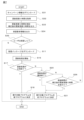
- FIG. 3 is an explanatory diagram for explaining software update by OTA according to the memory configuration of the ECU.
- FIG. 3 shows each step of download, installation, activation, and update completion confirmation among the plurality of steps shown in FIG. 2 as "update status”.
- FIG. 3 shows the state of the vehicle 1 in each update state as "vehicle state", the operation of the update target ECU as "target ECU”, and the user state as "user”.
- FIG. 3A shows an example of the software update flow when the ECU has a single bank memory configuration
- FIG. 3B shows an example of the software update flow when the ECU has a double bank memory configuration. be.
- the vehicle 1 when the memory configuration of the update target ECU is a single bank, the vehicle 1 is in a state in which the vehicle 1 can run (the ignition switch 13 is turned on), and the delivery package is "downloaded". . After the download is completed, when the ignition switch 13 is switched from ON to OFF while the vehicle 1 is stopped, a "consent request" is made to ask the user to approve the start of the update process.
- a user outside the vehicle 1 performs an operation input while confirming various types of information regarding software update on the user terminal 3, and performs a procedure regarding software update.
- the user terminal 3 receives information (for example, "update software Do you want to do this?”), and two icons that can be operated by the user, an icon indicating acceptance (for example, displaying “now”) and an icon indicating rejection (for example, displaying “later”). Is displayed.
- information for example, "update software Do you want to do this?”
- two icons that can be operated by the user, an icon indicating acceptance (for example, displaying “now”) and an icon indicating rejection (for example, displaying “later”). Is displayed.
- the vehicle 1 performs "installation" using the update data. Specifically, in the flash memory of the ECU, rewriting processing is performed to write a new program after deleting the old program.
- the vehicle 1 can "download" the distribution package while the vehicle 1 is in a drivable state, and also "install” the data for updating. ” is performed.
- the microcomputer of the ECU is executing the program (old program) stored in the first memory
- writing processing for writing the new program is performed in the second memory.
- an "acceptance request” is made to ask the user for consent to start the update process.
- the user terminal 3 displays, for example, information requesting approval to start the update process, an icon indicating approval, and an icon indicating refusal.
- “activation” is performed to change the read destination memory of the microcomputer from the first memory to the second memory. After that, the software update is completed through the process of restarting the power source of the vehicle 1 .
- the specific content of the software update process includes differences between "install” and “activate” and “activate”.
- the passenger is requested to approve the start of the update process, and when the passenger performs an operation of accepting the start of the update process, the vehicle 1 executes the update process.
- the update process is completed, the user can know that the update process has been completed through the update completion notice displayed on the user terminal 3 . For example, when there is a first user at home and a second user using the vehicle 1, the second user parks the vehicle 1 in the parking lot at home and switches the ignition switch from on to off. Assume that a software update procedure is performed via the terminal 3 .
- the software update device 10 attempts to solve the above problem by the following configuration and method.
- the software update device 10 has a controller 40 .
- FIG. 4 is an example of functional blocks of the controller 40 of the software update device 10.
- the controller 40 is configured by a computer having hardware and software, and has a memory storing a program and a CPU etc. for executing the program stored in this memory.
- an MPU, DSP, ASIC, FPGA, or the like can be used instead of or together with the CPU.
- the controller 40 includes, as functional blocks, an information acquisition unit 41, a storage unit 42, an output unit 43, a start determination unit 44, an update processing execution unit 45, a control unit 50, a power supply It has a process execution unit 51 .
- the controller 40 implements each function of the functional blocks by software stored in memory.
- the information acquisition unit 41 acquires update processing information regarding software update from the server 2 via the in-vehicle communication device 11 .
- the update processing information includes the campaign information and distribution package described above.
- the information acquisition unit 41 also acquires a signal indicating the ON state or OFF state of the ignition switch 13 from the ignition switch 13 .
- the information acquisition unit 41 also acquires a signal indicating a user's operation from the vehicle-mounted terminal 12 .
- the information acquisition unit 41 also acquires a signal indicating a user's operation on the user terminal 3 via the server 2 .
- the information acquisition unit 41 acquires a signal indicating that the user has pressed the consent display from the user terminal 3 via the server 2. do.
- the information acquisition unit 41 transmits a signal indicating that the user has pressed the refusal display from the user terminal 3 via the server 2. get.
- the storage unit 42 functions as a storage device that stores information acquired from the server 2 among the information acquired by the information acquisition unit 41 .
- a non-volatile recording medium such as flash memory is used.
- the storage unit 42 stores campaign information and distribution packages acquired from the server 2 . Further, the storage unit 42 may store information on the ECU mounted on the vehicle 1 (memory configuration of the ECU, etc.). Various information stored in the storage unit 42 is used for processing in the update processing execution unit 45 .
- the output unit 43 outputs consent request information that asks the user to approve the start of update processing by the update processing execution unit 45 .
- consent request information include images and sounds, but the method of requesting the user's consent is not particularly limited.
- the output unit 43 may transmit an audio signal requesting the user to approve the start of the update process to the server 2 via the in-vehicle communication device 11 together with or instead of the image signal.
- the consent request information transmitted from the in-vehicle communication device 11 is received by the server 2 and then transmitted from the server 2 to the user terminal 3 .
- the output unit 43 outputs consent request information when a predetermined output condition is satisfied.
- the output unit 43 determines whether or not the ignition switch 13 has been turned off by the passenger based on the information acquired by the information acquisition unit 41 .
- the output unit 43 outputs approval request information when the signal indicating the state of the ignition switch 13 is switched from the ON state to the OFF state.
- the output condition by the output part 43 is an example, and other conditions may be sufficient as output conditions.
- the start determination unit 44 determines whether or not to start update processing by the update processing execution unit 45 .
- the start determination unit 44 determines to start the update process when the user approves the start of the update process in response to the approval request information output by the output unit 43, and the user refuses to start the update process in response to the approval request information. If so, it is determined not to start the update process.
- the information acquisition unit 41 acquires consent information from the server 2, and the start determination unit 44 starts the update process, as described above. Determine to start.
- the information acquisition unit 41 acquires the refusal information from the server 2 as described above, and the start determination unit 44 Determine not to start processing.
- the update processing execution unit 45 executes update processing according to response information, which is the user's response to the consent request information.
- the update process execution unit 45 executes the update process when the start determination unit 44 determines to start the update process, and postpones the execution of the update process when the start determination unit 44 determines not to start the update process. do.
- the update processing completion notification is input from the update target ECU to the update processing execution unit 45 , and the update processing execution unit 45 transmits the input notification to the control unit 50 . Output.
- the start determination unit 44 determines not to start the update process
- the execution of the update process may be postponed, and the update process execution unit 45 may perform other processes.
- the update processing execution unit 45 includes an installation execution unit and an activation execution unit according to the update target ECU memory configuration as functional blocks for executing the update processing. As shown in FIG. 4, the update processing execution unit 45 includes a first installation execution unit 46 and a first activation execution unit 47 that support a single bank memory configuration, and a second installation execution unit 47 that supports a double bank memory configuration. 48 and a second activation execution unit 49 . As described with reference to FIG. 3, depending on whether the memory configuration of the ECU is single bank or double bank, the contents of the "install" and "activate" processes differ. Therefore, in this embodiment, a plurality of installation execution units and a plurality of activation execution units are provided.
- the new program is installed by the first installation execution unit 46 and the new program is activated by the first activation execution unit 47 .
- the second installation execution unit 48 installs the new program
- the second activation execution unit 49 activates the new program.
- the update processing execution unit 45 determines the memory configuration of the update target ECU from the information about the ECUs mounted on the vehicle 1 stored in the storage unit 42 .
- the first installation execution unit 46 executes installation processing for writing the new program after deleting the old program stored in the flash memory.
- the first activation executing section 47 executes an activation process of causing a microcomputer included in an ECU to be updated to read the new program written in the flash memory.
- the second installation executing section 48 installs the second memory in which the old program is not stored. , execute the installation process to write the new program.
- the second activation execution unit 49 executes activation processing for switching the read destination of the program by the microcomputer of the update target ECU from the first memory to the second memory.
- the control unit 50 determines the target program to be executed by the update target ECU based on the estimated time required for the update process.
- the estimated time required for update processing is the estimated update processing time calculated by the server 2 .
- the specific content of the update process differs between "install”, “activate”, and “activate” depending on the memory configuration of the update target ECU. Therefore, the breakdown of the update processing estimated time calculated by the server 2 changes according to the specifications of the ECU to be updated.
- the update process estimated time is composed of the time required for the installation process and the time required for the activation process.
- the update processing estimated time is configured by the time required for activation.
- control unit 50 causes the update target ECU to execute the old program corresponding to the pre-update software. On the other hand, when the update process is completed within the update process estimated time, the control unit 50 causes the update target ECU to execute a new program corresponding to the updated software.
- the control unit 50 activates a timer for measuring the update processing time, and starts measuring the elapsed time from the start of the update processing.
- the control unit 50 waits for an update processing completion notification from the update processing execution unit 45 while comparing the elapsed time and the update processing estimated time.
- the control unit 50 causes the microcomputer included in the update target ECU to execute the new program.
- the control unit 50 causes the microcomputer included in the update target ECU to execute the old program.
- the control unit 50 executes different processes according to the memory configuration of the update target ECU.
- the control unit 50 performs rollback processing on the update target ECU.
- Rollback is writing or writing back to restore the flash memory of the update target ECU to a predetermined state, such as restoring the version of the program when interrupting the update process.
- rollback means returning the state of the update target ECU from the user's perspective to the state before the update process was started.
- the rollback process known at the time of filing of the present application can be applied to the control unit 50 . For example, if the distribution package includes a rollback program, the control unit 50 uses the rollback program to perform rollback processing on the update target ECU.
- the control unit 50 stores the new program in the flash memory of the ECU to be updated. For example, if the old program is stored in the first memory and the new program is written in the second memory, the control unit 50 stores the new program written in the second memory. As in the example of FIG. 3B, when the installation is performed with the ignition switch 13 turned on and the writing of the new program to the second memory is completed, the control unit 50 To save a second program even if update processing is not completed.
- the power supply processing execution unit 51 outputs a control signal to the power supply system ECU 14D for setting the output power of the drive battery, which is the IG power supply of the vehicle 1, to zero, thereby turning off the ignition of the vehicle 1.
- the flowchart shown in FIG. 5 is executed by the controller 40 of the software update device 10 shown in FIG.
- the flowchart of FIG. 5 is a flowchart when the memory configuration of the update target ECU is a single bank.
- the flowchart of FIG. 6 is a flowchart of download (step S2) to confirmation of update completion (step S5) shown in FIG.
- step S11 the controller 40 acquires (downloads) the distribution package from the server 2 via the in-vehicle communication device 11.
- the distribution package includes update data, authentication data used for authentication processing of the update data, and update processing estimated time.
- step S12 the controller 40 acquires an update processing estimated time from the distribution package acquired in step S11.
- step S13 the controller 40 determines whether the ignition switch 13 has been switched from ON to OFF by the passenger's operation.
- the controller 40 acquires a signal indicating an operation by the passenger from the ignition switch 13 . If the ignition switch 13 is switched from ON to OFF by the passenger, the process proceeds to step S14, and if the ignition switch 13 remains ON, the process waits in step S13 until the ignition switch is switched from ON to OFF by the passenger.
- step S14 the controller 40 outputs consent request information requesting the user's consent to start the software update process.
- the controller 40 transmits consent request information to the server 2 via the in-vehicle communication device 11 . After that, the consent request information is transmitted from the server 2 to the user terminal 3 .
- step S15 the controller 40 determines whether or not the user has consented to the consent request information output in step S14.
- consent information is transmitted from the user terminal 3 to the server 2 as the user's reply information to the consent request information.
- the controller 40 acquires consent information from the server 2 and determines to start the update process. In this case, the process proceeds to step S16.
- refusal information is transmitted from the user terminal 3 to the server 2 as the user's reply information to the consent request information.
- the controller 40 acquires the refusal information from the server 2 and determines not to start the update process. In this case, the process proceeds to step S19.
- step S15 the process proceeds to step S16.
- step S16 the controller 40 causes the update target ECU to start the software update process. Specifically, when the memory configuration of the ECU is a single bank, the controller 40 executes installation processing and activation processing as shown in the example of FIG. 3(A). For the specific contents of each process, the description given above is used. Also, in this step, the controller 40 activates a timer for measuring the update processing time, and starts measuring the elapsed time from the start of the update processing.
- step S17 the controller 40 determines whether or not the update process started in step S16 has ended normally.
- the controller 40 determines that the update processing has ended normally. In this case, the process proceeds to step S18.
- the controller 40 determines that the update process has not been completed normally. In this case, the process proceeds to step S20.
- step S17 If it is determined in step S17 that the update process has ended normally, the process proceeds to step S18.
- step S18 the controller 40 determines the target program to be executed by the update target ECU as the new program, and causes the update target ECU to execute the new program.
- step S19 the controller 40 executes a process of turning off the ignition of the vehicle 1 as a process corresponding to the operation of the ignition switch by the passenger at step S13. Specifically, the controller 40 outputs a control signal for turning off the ignition of the vehicle 1 to the power supply system ECU 14D.
- step S17 If it is determined in step S17 that the update process has not ended normally, the process proceeds to step S29.
- step S20 the controller 40 determines whether or not the update process has ended abnormally. For example, when an abnormal end notification is input from the update target ECU, the controller 40 determines that the update process has ended abnormally. In this case, the process proceeds to step S21. On the other hand, for example, the controller 40 determines that the update process has not ended abnormally when an abnormal end notification is not input from the update target ECU. In this case, the process proceeds to step S22.
- step S21 the controller 40 determines that the target program to be executed by the update target ECU is the old program, and causes the update target ECU to execute the old program. For example, the controller 40 performs rollback processing on the update target ECU. After the process of step S21 is completed, the process proceeds to step S19, and the controller 40 executes the process of step S19 described above.
- step S20 If it is determined in step S20 that the update process has not ended abnormally, the process proceeds to step S22.
- step S22 the controller 40 determines whether or not the elapsed time starting to be measured from step S16 has exceeded the update process estimated time acquired in step S12. When the controller 40 determines that the elapsed time has exceeded the update process estimated time, the process proceeds to step S21, and the controller 40 executes the process in step S21 described above. On the other hand, if the controller 40 determines that the elapsed time has not exceeded the update process estimated time, the process returns to step S17, and the processes in the above-described steps are executed until the process in FIG. 5 ends. .
- the controller 40 executes the installation process using the new program acquired in step S11 after the process of step S11 is completed and before proceeding to step S12. Specifically, when the memory configuration of the ECU is a double bank, the controller 40 executes the installation process as shown in the example of FIG. 3(B). For the specific contents of the processing, the above description is used.
- step S12 the controller 40 acquires the estimated activation processing time as the update processing estimated time. Therefore, the estimated processing time of the activation process is compared with the elapsed time in step S22.
- step S16 the controller 40 executes activation processing as software update processing for the update target ECU. When the memory configuration of the ECU is a double bank, the controller 40 executes activation processing as shown in the example of FIG. 3(B). For the specific contents of the processing, the above description is used.
- step S21 the controller 40 saves the new program written in the memory, and switches the reading destination of the microcomputer of the ECU to the memory in which the old program is stored.
- the software update device 10 is a software update device that updates the software of the body system ECU 14A, the travel system ECU 14B, and the multimedia system ECU 14C mounted on the vehicle 1.
- the software update device 10 includes an output unit 43 , an update processing execution unit 45 and a control unit 50 .
- the output unit 43 acquires update processing information regarding software update from the server 2 .
- the update processing execution unit 45 executes update processing in accordance with reply information, which is the user's reply to the consent request information.
- the control unit 50 determines a target program to be executed by the update target ECU based on the update process estimated time. If the update processing is not completed within the update processing estimated time, the control unit 50 causes the update target ECU to execute the old program. to execute.
- the surrounding environment of the ECU to be updated is considered to be the cause of the error in which the software update process does not end.
- the update target ECU executes self-diagnostic processing based on the detection result of the temperature sensor, thereby reducing the calculation load of the microcomputer. It is believed that when the computational load of the microcomputer decreases, the processing speed of the microcomputer decreases, leading to an error in which the update process does not end.
- the software update system 100 executes Since the target program to be used can be determined, the vehicle 1 is ready for use, and the user can use the vehicle 1 .
- the information acquisition unit 41 acquires an update processing estimated time from the server 2 .
- the program to be executed by the ECU to be updated can be determined without the software updating device 10 calculating an update process estimate, so the calculation load on the software updating device 10 can be reduced.
- the update target ECU has a flash memory that stores the old program
- the update processing execution unit 45 includes a first installation execution unit 46 and a first activation execution unit 47 .
- the first install executing unit 46 executes an install process of writing the new program into the flash memory.
- the first activation execution unit 47 executes activation processing for causing the microcomputer to read the new program written in the flash memory. If the update processing is not completed within the update processing estimated time, the control unit 50 performs rollback processing on the update target ECU. As a result, even if the update target ECU has a single bank memory configuration, it is possible to determine the target program to be executed by the update target ECU in response to the occurrence of an error that does not end the update process.
- the update target ECU has a flash memory composed of a first memory for storing the old program and a double bank of the second memory. and a second activation executing section 49 .
- the second installation executing section 48 writes the new program into the second memory.
- the second activation execution unit 49 executes activation processing for switching the reading destination of the program of the microcomputer from the first memory to the second memory.
- the control unit 50 saves the new program written in the second memory as processing when the update processing is not completed within the update processing estimated time. Since the new program can be stored in the second memory of the update target ECU, it is not necessary to install the new program when the update process is performed again, and the calculation load of the software update device 10 can be reduced.
- the server 2 calculates the estimated update processing time based on at least one of the size of the update data and the type of the ECU to be updated. As a result, the calculation load on the software update device 10 can be reduced.
- the software update device 10 has explained an example of a configuration in which the update processing estimated time is obtained from the server 2.
- the entity that calculates the update processing estimated time is not limited to the server 2.
- the update device 10 may calculate the estimated update processing time.
- the controller 40 has, as a functional block, a calculator that calculates an update process estimated time based on at least one of the data size of the update data and the type of the ECU to be updated.
- a calculator that calculates an update process estimated time based on at least one of the data size of the update data and the type of the ECU to be updated.
- the calculation unit refers to the map and calculates the estimated update processing time according to the data size. may be calculated. Further, for example, the calculation unit may calculate the update process estimated time longer as the data size of the update data is larger.
- the control device 23 may calculate the update process estimated time based on the specifications of the microcomputer and/or flash memory included in the ECU.
- the example of the calculation method in the control device 23 described above is used.
- the calculation load on the server 2 can be reduced by calculating the update processing estimated time by the software update device 10 .
- the timing at which the controller 40 calculates the update processing estimated time is not particularly limited as long as it is before the update processing is started. Instead of getting it, calculate the estimated update processing time.
- step S3 the installation (step S3) and activation (step S4) among the steps of software update by OTP shown in FIG.
- step S2 an example including download (step S2) will be described.
- the campaign information is notified in step S1
- the user is asked to approve the start of updating, and if the user approves, download to activation are performed sequentially without asking the user for approval.
- One example is a situation in which the software is updated by OTP while the vehicle is not in use by the user, such as when the vehicle is parked in the parking lot of the user's home.
- the software update system according to the second embodiment differs from the software update system 100 according to the first embodiment in the estimated time calculated by the server 2 and the functional blocks provided in the controller 60 of the software update device 10. It has the same configuration as the software update system 100 according to the first embodiment. Therefore, the above description is used for the same configuration as that of the first embodiment.
- the server 2 combines the estimated download time until the download of the distribution package is completed with the update processing estimated time in the first embodiment, and calculates the estimated time until the update of the software is completed (update completion estimated time).
- the server 2 distributes campaign information including update completion estimated time to one or more vehicles 1 .
- the control device 23 of the server 2 calculates the estimated download time based on the data size of the distribution package. For example, if a map indicating the relationship between the data size of the distribution package and the estimated download time is stored in advance in the database 22, the control device 23 refers to the map and calculates the estimated download time according to the data size. . Also, for example, the control device 23 calculates a longer estimated download time as the data size of the distribution package is larger.
- FIG. 6 is an example of functional blocks of the controller 60 of the software update device 10 according to this embodiment.
- the controller 60 has a communication status acquisition unit 52, a correction unit 53, and a notification unit 54 in addition to the functional blocks in the first embodiment.
- the functions of the output section 43 are partially different from those in the first embodiment.
- the controller 60 implements each function of the functional blocks by software stored in memory. For functional blocks similar to those in the first embodiment, the description in the first embodiment is used.
- the output unit 43 outputs consent request information requesting the user whether or not to approve the update of software including not only the update processing by the update processing execution unit 45 but also the download of the distribution package from the server 2. to output A specific example of the consent request information and a method of transmitting it to the user terminal 3 refer to the description in the first embodiment. Further, in this embodiment, the output unit 43 outputs the approval request information after the campaign information is acquired by the information acquisition unit 41 and before the information acquisition unit 41 acquires the distribution package.
- the communication status acquisition unit 52 acquires communication status information regarding the communication status with the server 2.
- the communication status acquisition unit 52 detects a communication status between the in-vehicle communication device 11 and the communication device 21 of the server 2, and acquires the detected communication status as communication status information. For example, when communication is not established between the in-vehicle communication device 11 and the communication device 21, the communication status acquisition unit 52 detects that the communication status is abnormal.
- the communication status acquisition unit 52 may also calculate the delay time in wireless data communication.
- the delay time includes a fixed delay time determined by the capability of the in-vehicle communication device 11 and a delay time that varies depending on the number of communication devices accessing the wireless communication network 4, the size of data to be communicated (communication fee), and the like.
- a technique for acquiring the communication status known at the time of filing of the present application can be applied.
- the correction unit 53 acquires the estimated update completion time from the campaign information, and corrects the estimated update completion time based on the communication status information acquired by the communication status acquisition unit 52.
- the estimated download time calculated by the server 2 does not take into consideration the actual communication status, so there is a possibility that the estimated download time and the actual download time may differ. For example, since the communication state between the in-vehicle communication device 11 and the communication device 21 is good, the delay time in wireless data communication is shortened, and the actual download time may be earlier than the estimated download time.
- the correction unit 53 shortens the estimated download time according to the delay time in wireless data communication.
- the correction unit 53 extends the estimated download time according to the delay time in wireless data communication included in the communication status information.
- the notification unit 54 calculates an estimated update time (hereinafter referred to as a corrected estimated update time ) information is output.
- the notification unit 54 transmits information on the updated estimated time after correction to the server 2 via the in-vehicle communication device 11 .
- the information of the updated estimated time after correction transmitted from the in-vehicle communication device 11 is received by the server 2 and then transmitted from the server 2 to the user terminal 3 .
- the user is notified of the estimated time after correction.
- the notification unit 54 sets the update estimate time after correction to the update estimate time calculated by the server 2 (hereinafter referred to as the update estimate time before correction). If it is longer than the estimated time by a predetermined threshold time or more, the updated estimated time after correction may be output.
- the predetermined threshold time is, for example, a predetermined time in units of minutes such as 5 minutes. If the actual update time is expected to be significantly later than the estimated time, it is likely to affect the user's decision to accept or reject the update. Notify the update time after correction.
- the notification unit 54 does not have to output the estimated time after correction. If the actual update time is expected to be sooner than the estimated time, it is unlikely to affect the user's decision to accept or reject the update; Do not notify the user of the time.
- the flowchart shown in FIG. 7 is executed by the controller 60 of the software update device 10 shown in FIG.
- the flowchart of FIG. 7 is a flowchart when the memory configuration of the update target ECU is a single bank.
- the flowchart of FIG. 7 is a flowchart of campaign information notification (step S1) to confirmation of update completion (step S5) shown in FIG.
- the flowchart of FIG. 7 also includes some of the same steps as the flowchart of FIG.
- the same steps as in FIG. 6 are denoted by the same reference numerals as those in FIG. 6, and the same steps as in FIG. 6 are described above.
- the ignition switch 13 is turned off, and step S19 shown in FIG. 6 is omitted.
- the process in step S19 shown in FIG. 6 may be performed.
- step S31 the controller 60 acquires (downloads) campaign information from the server 2 via the in-vehicle communication device 11.
- the campaign information includes the data size of the update data, information identifying the ECU to be updated, information on the version of the software to be updated, outline description of the function to be updated, estimated download time, estimated update processing time, and the like.
- step S32 the controller 60 acquires the estimated update time obtained by adding the estimated download time and the estimated update process time from the campaign information acquired in step S31.
- step S33 the controller 60 corrects the estimated download time out of the estimated update time acquired in step S32 based on the communication status information regarding the communication status with the server 2.
- the controller 60 outputs a corrected estimated update time obtained by adding the corrected estimated download time and the estimated update process time acquired in step S31.
- the controller 60 transmits the updated estimated time after correction to the user terminal 3 via the in-vehicle communication device 11 and the server 2 .
- step S34 the controller 60 outputs consent request information requesting the user's consent to update the software.
- the controller 60 transmits consent request information to the user terminal 3 via the in-vehicle communication device 11 and the server 2 .
- step S35 the controller 60 determines whether or not the user has consented to the consent request information output in step S34.
- consent information is transmitted from the user terminal 3 to the server 2 as the user's reply information to the consent request information.
- the controller 60 obtains consent information from the server 2 and determines to start updating the software.
- the controller 60 activates a timer for measuring the download time and update processing time of the distribution package, and measures the elapsed time from the download of the distribution package. Begin to.
- refusal information is transmitted from the user terminal 3 to the server 2 as the user's reply information to the consent request information.
- the controller 60 acquires the refusal information from the server 2, and the processing in the flowchart shown in FIG. 7 ends.
- step S35 If it is determined in step S35 that the user has consented, the process advances to step S11, and download of the distribution package by the controller 60 is started in the same manner as in the first embodiment. After the download of the distribution package is completed, the process advances to step S16, and update processing by the controller 60 is started as in the first embodiment.
- Step S37 is a step corresponding to step S22 shown in FIG.
- the controller 60 compares the measured time that started to be measured when the user consented in step S35 and the revised estimated update time corrected in step S33, and determines the updated estimated time after the correction of the elapsed time. is exceeded. Since this step is the same as step S22 except that the elapsed time calculation start timing and the elapsed time comparison target are different, the above description is used.
- the software update device 10 includes the communication status acquisition unit 52, the correction unit 53, and the notification unit 54.
- the communication status acquisition unit 52 acquires communication status information regarding the communication status with the server 2 .
- the correction unit 53 corrects the estimated update time based on the communication status information.
- the notification unit 54 outputs information on the updated estimated time after correction. This makes it possible to improve the accuracy of the estimated download time.
- the estimated update time including the estimated download time can be notified to the user, the user can recognize the estimated time required for updating the software including the download.
- the notification unit 54 when the estimated update time after correction is longer than the estimated update time before correction by a predetermined threshold time or more, the notification unit 54 outputs information about the estimated update time after correction. .
- the notification unit 54 outputs information about the estimated update time after correction.
- the notification unit 54 does not output information on the corrected update estimated time when the corrected update estimated time is shorter than the pre-corrected update estimated time.
- the process of notifying the user of the estimated time can be omitted. can be done.
- the time required for the entire software update flow by OTP can be shortened.
- the flow in which the distribution package is downloaded while the vehicle 1 is in a drivable state has been described as an example. It can be replaced with "an estimated update time obtained by adding the estimated download time and the estimated update process time" in the second embodiment.
- the configuration in which the controller 40 has a calculation unit for calculating the estimated update process time was described as an example.
- a calculation unit for calculating an estimated download time When the vehicle 1 travels along the travel route, the information acquisition unit 41 acquires information on the travel route of the vehicle 1 from the navigation system (not shown) of the vehicle 1 .
- the calculation unit calculates the estimated download time based on the communication status information acquired by the communication status acquisition unit 52 and the travel route of the vehicle 1 acquired by the information acquisition unit 41 .
- the calculator acquires communication status information of the wireless communication network 4 at a plurality of points on the travel route from a communication map indicating the communication status of the wireless communication network 4 provided by the carrier.
- the calculation unit calculates an estimated download time when the vehicle 1 travels along the travel route based on the communication status information on the travel route of the vehicle 1 . It is possible to improve the accuracy of the estimated download time when downloading the distribution package while the vehicle 1 is in a drivable state.
- the configuration for correcting the estimated update time was described as an example, but the configuration is not limited to the configuration for correcting the estimated update time.
- the controller 60 may determine the program to be executed by the ECU to be updated using the estimated update time before correction.
- the controller 60 may output approval request information to ask the user to approve the start of the process before starting the process of each step.
- the controller 60 executes rollback processing for the ECU to be updated as processing when the elapsed time exceeds the update estimated time (including the case of correction) when the memory configuration is a double bank. good too.
- the actual download time is longer than the estimated download time and it is determined that the elapsed time exceeds the corrected estimated update time during the installation process (Yes in step S36). judgement).
- the controller 60 since the writing of the new program to the second memory is not completed, the controller 60 performs rollback processing on the update target ECU. Even if the update target ECU has a double-bank memory configuration and the writing of the new program is not completed, the target program to be executed by the update target ECU can be determined, so the vehicle 1 is ready for use. , the user can use the vehicle 1 .
- the controller 60 may include a measuring unit that measures the actual required time from the start of the update process to the completion of the update process.
- the output unit 43 transmits information on the actual required time required for the update process to the server 2 via the in-vehicle communication device 11 .
Abstract
Description
本実施形態に係るソフトウェア更新装置10は、図1に示すように、ソフトウェア更新システム100の一部として実現される。図1は、本実施形態に係るソフトウェア更新システム100の一例を示すブロック図である。ソフトウェア更新システム100は、車両1の電子制御装置(以下、ECU(Electronic Control Unit)と称する)が実行する、車両制御や診断等のソフトウェアを、OTA(Over The Air)により更新可能なシステムである。このようなOTAによりソフトウェアを更新することは、FOTA(Firmware Over The Air)とも称される。ECUのソフトウェアは、ECUが備えるマイコンがプログラムを実行することで、実現される。本実施形態では、無線によるECUのソフトウェア更新として、ECUのマイコンが実行するプログラムを無線により書き換える場合を例に挙げて説明するが、ソフトウェア更新システム100は、例えば、車両1のナビゲーションシステムで使用される地図データ、ECUで使用される制御パラメータ等、各種ソフトウェアで使用されるデータを無線で書き換える場合にも適用することができる。またソフトウェア更新システム100は、ECUにFPGA(Field Programmable Gate Array)が用いられている場合、FPGAの機能(ロジック)を無線で書き換える場合にも適用することができる。また図1では、車両1として一台の車両が図示されているが、ソフトウェア更新システム100は、複数の車両1を対象にして、ソフトウェアの更新可能なシステムである。 <<First embodiment>>
The
次に、第2実施形態に係るソフトウェア更新装置について説明する。上述した第1実施形態では、図2に示すOTPによるソフウェア更新の各ステップのうち、インストール(ステップS3)とアクティベート(ステップS4)を例に挙げて説明したが、本実施形態では、インストール及びアクティベートに加えて、ダウンロード(ステップS2)を含めた例について説明する。例えば、ステップS1でのキャンペーン情報の通知後に更新開始の承諾をユーザに求め、ユーザが承諾した場合に、その後、ユーザに承諾を求めることなく、ダウンロード~アクティベートが順次行われる場面が想定される。一例として、車両が自宅の駐車場に駐車中等、車両がユーザに使用されてない状況で、OTPによるソフトウェア更新が行われる場面が挙げられる。 <<Second embodiment>>
Next, a software update device according to the second embodiment will be described. In the above-described first embodiment, the installation (step S3) and activation (step S4) among the steps of software update by OTP shown in FIG. In addition, an example including download (step S2) will be described. For example, after the campaign information is notified in step S1, the user is asked to approve the start of updating, and if the user approves, download to activation are performed sequentially without asking the user for approval. One example is a situation in which the software is updated by OTP while the vehicle is not in use by the user, such as when the vehicle is parked in the parking lot of the user's home.
1…車両
10…ソフトウェア更新装置
40…コントローラ
41…情報取得部
42…記憶部
43…出力部
44…開始判定部
45…更新処理実行部
46…第1インストール実行部
47…第1アクティベート実行部
48…第2インストール実行部
49…第2アクティベート実行部
50…制御部
51…電源処理実行部
11…車載通信装置
12…車載端末
13…イグニッションスイッチ
14A…ボディ系ECU
14B…走行系ECU
14C…マルチメディア系ECU
14D…電源系ECU
2…サーバー
21…通信装置
22…データベース
23…制御装置
3…ユーザ端末
31…端末通信装置
32…端末HMI
33…端末制御装置 DESCRIPTION OF
14B... Driving system ECU
14C: multimedia system ECU
14D... Power system ECU
DESCRIPTION OF
33 Terminal control device
Claims (14)
- 車両に搭載される車載制御装置のソフトウェアを更新するソフトウェア更新装置であって、
前記車両の外部に設けられたサーバーから、前記ソフトウェアの更新に関する更新処理情報を取得する情報取得部と、
前記ソフトウェアの更新を承諾するかユーザに求める承諾要求情報を出力する出力部と、
前記承諾要求情報に対する前記ユーザの回答である回答情報に応じて、前記ソフトウェアの更新処理を実行する実行部と、
前記更新に要する見積り時間に基づき、前記車載制御装置が実行する対象プログラムを決定する制御部を備え、
前記制御部は、
前記見積り時間内に前記更新が完了しない場合、更新前ソフトウェアに対応したプログラムを、前記車載制御装置に実行させ、
前記見積り時間内に前記更新が完了した場合、更新済みソフトウェアに対応したプログラムを、前記車載制御装置に実行させるソフトウェア更新装置。 A software update device for updating software of an in-vehicle control device mounted in a vehicle,
an information acquisition unit that acquires update processing information related to updating the software from a server provided outside the vehicle;
an output unit for outputting consent request information asking a user to approve the update of the software;
an execution unit that executes update processing of the software in accordance with response information that is the user's response to the consent request information;
A control unit that determines a target program to be executed by the in-vehicle control device based on the estimated time required for updating,
The control unit
if the update is not completed within the estimated time, causing the in-vehicle control device to execute a program corresponding to the pre-update software;
A software update device that causes the vehicle-mounted control device to execute a program corresponding to the updated software when the update is completed within the estimated time. - 請求項1に記載のソフトウェア更新装置であって、
前記情報取得部は、前記サーバーから、前記見積り時間を取得するソフトウェア更新装置。 The software update device according to claim 1,
The software update device, wherein the information acquisition unit acquires the estimated time from the server. - 請求項1に記載のソフトウェア更新装置であって、
前記ソフトウェアを更新するために用いるデータのサイズ、及び前記車載制御装置の種別のうち少なくとも何れか一方に基づき、前記見積り時間を算出する算出部を備えるソフトウェア更新装置。 The software update device according to claim 1,
A software update device comprising a calculator that calculates the estimated time based on at least one of a size of data used for updating the software and a type of the on-vehicle control device. - 請求項1~3の何れかに記載のソフトウェア更新装置であって、
前記サーバーとの間の通信状況に関する通信状況情報を取得する通信状況取得部と、
前記通信状況情報に基づき、前記見積り時間を補正する補正部と、
前記補正された見積り時間の情報を出力する通知部を備えるソフトウェア更新装置。 The software update device according to any one of claims 1 to 3,
a communication status acquisition unit that acquires communication status information about the communication status with the server;
a correction unit that corrects the estimated time based on the communication status information;
A software update device comprising a notification unit that outputs information on the corrected estimated time. - 請求項4に記載のソフトウェア更新装置であって、
前記通知部は、前記補正された見積り時間が前記見積り時間よりも所定の閾値時間以上長い場合、前記補正された見積り時間の情報を出力するソフトウェア更新装置。 The software update device according to claim 4,
The notification unit is a software update device that outputs information on the corrected estimated time when the corrected estimated time is longer than the estimated time by a predetermined threshold time or longer. - 請求項4又は5に記載のソフトウェア更新装置であって、
前記通知部は、前記補正された見積り時間が前記見積り時間よりも短い場合、前記補正された見積り時間の情報を出力しないソフトウェア更新装置。 The software update device according to claim 4 or 5,
The software updating device, wherein the notification unit does not output information on the corrected estimated time when the corrected estimated time is shorter than the estimated time. - 請求項1又は2に記載のソフトウェア更新装置であって、
前記サーバーとの間の通信状況を示す通信情報を取得する通信状況取得部と、
前記見積り時間を算出する算出部を備え、
前記情報取得部は、前記車両の走行経路の情報を取得し、
前記算出部は、前記車両の走行経路及び前記通信状況に基づき、前記見積り時間を算出するソフトウェア更新装置。 The software update device according to claim 1 or 2,
a communication status acquisition unit that acquires communication information indicating the status of communication with the server;
A calculation unit that calculates the estimated time,
The information acquisition unit acquires information on the travel route of the vehicle,
The software updating device, wherein the calculation unit calculates the estimated time based on the travel route of the vehicle and the communication status. - 請求項1~7の何れかに記載のソフトウェア更新装置であって、
前記車載制御装置は、古いバージョンの前記ソフトウェアを実現するための第1プログラムを格納する第1メモリを有し、
前記実行部は、
前記第1プログラムを前記第1メモリから削除した後に、前記第1メモリに、新しいバージョンの前記ソフトウェアを実現するための第2プログラムを書き込むインストール処理を実行するインストール実行部と、
前記第1メモリに書き込まれた前記第2プログラムを読み込ませるアクティベート処理を実行するアクティベート実行部を含み、
前記制御部は、前記見積り時間内に前記更新処理が完了しない場合、前記車載制御装置に対してロールバック処理を実行するソフトウェア更新装置。 The software update device according to any one of claims 1 to 7,
The in-vehicle control device has a first memory storing a first program for implementing the old version of the software,
The execution unit
an installation execution unit that executes installation processing to write a second program for realizing a new version of the software into the first memory after deleting the first program from the first memory;
an activation execution unit that executes an activation process for reading the second program written in the first memory;
The software updating device, wherein the control unit performs rollback processing on the in-vehicle control device when the updating processing is not completed within the estimated time. - 請求項1~7の何れかに記載のソフトウェア更新装置であって、
前記車載制御装置は、古いバージョンの前記ソフトウェアを実現するための第1プログラムを格納する第1メモリと、第2メモリを有し、
前記実行部は、
前記第2メモリに、新しいバージョンの前記ソフトウェアを実現するための第2プログラムを書き込むインストール実行部と、
プログラムの読込先を、前記第1メモリから前記第2メモリに切り替えるアクティベート処理を実行するアクティベート実行部を含み、
前記制御部は、前記見積り時間内に前記更新処理が完了しない場合の処理として、前記第2メモリに書き込まれた前記第2プログラムを保存させるソフトウェア更新装置。 The software update device according to any one of claims 1 to 7,
The in-vehicle control device has a first memory storing a first program for implementing the old version of the software, and a second memory,
The execution unit
an installation execution unit that writes a second program for realizing a new version of the software into the second memory;
an activation executing unit that executes activation processing for switching a program read destination from the first memory to the second memory;
The software update device, wherein the control unit saves the second program written in the second memory as processing when the update processing is not completed within the estimated time. - 請求項9に記載のソフトウェア更新装置であって、
前記制御部は、前記見積り時間内に前記更新が完了しない場合の処理として、前記車載制御装置に対してロールバック処理を実行するソフトウェア更新装置。 The software update device according to claim 9,
The software update device, wherein the control unit performs rollback processing on the in-vehicle control device as processing when the update is not completed within the estimated time. - 請求項1~7の何れかに記載のソフトウェア更新装置であって、
前記更新処理が開始してから完了するまでに要した実際の所要時間を計測する計測部を備え、
前記出力部は、前記実際の所要時間の情報を、前記サーバーに出力するソフトウェア更新装置。 The software update device according to any one of claims 1 to 7,
A measurement unit that measures the actual time required from the start of the update process to the completion of the update process,
The software update device, wherein the output unit outputs the information on the actual required time to the server. - 請求項1~11の何れかに記載のソフトウェア更新装置と、前記サーバーを含むソフトウェア更新システム。 A software update system including the software update device according to any one of claims 1 to 11 and the server.
- 請求項12に記載のソフトウェア更新システムであって、
前記サーバーは、前記ソフトウェアを更新するために用いるデータのサイズ、及び前記車載制御装置の種別のうち少なくとも何れか一方に基づき、前記見積り時間を算出するソフトウェア更新システム。 13. The software update system of claim 12,
The software update system, wherein the server calculates the estimated time based on at least one of a size of data used for updating the software and a type of the vehicle-mounted control device. - コントローラが、車両に搭載される車載制御装置のソフトウェアを更新するソフトウェア更新方法であって、
前記車両の外部に設けられたサーバーから、前記ソフトウェアの更新に関する更新処理情報を取得し、
前記ソフトウェアの更新を承諾するかユーザに求める承諾要求情報を出力し、
前記承諾要求情報に対する前記ユーザの回答である回答情報に応じて、前記ソフトウェアの更新処理を実行し、
前記更新に要する見積り時間内に前記更新が完了しない場合、更新前ソフトウェアに対応したプログラムを、前記車載制御装置に実行させ、
前記見積り時間内に前記更新が完了した場合、更新済みソフトウェアに対応したプログラムを、前記車載制御装置に実行させるソフトウェア更新方法。 A software update method in which a controller updates software of an in-vehicle control device mounted in a vehicle,
Acquiring update processing information related to updating the software from a server provided outside the vehicle;
outputting consent request information asking the user to approve the update of said software;
executing the software update process according to answer information, which is the user's answer to the consent request information;
if the update is not completed within the estimated time required for the update, causing the in-vehicle control device to execute a program corresponding to the pre-update software;
A software update method for causing the in-vehicle control device to execute a program corresponding to the updated software when the update is completed within the estimated time.
Priority Applications (2)
| Application Number | Priority Date | Filing Date | Title |
|---|---|---|---|
| PCT/JP2021/027686 WO2023007577A1 (en) | 2021-07-27 | 2021-07-27 | Software updating device, software updating system, and software updating method |
| CN202180100719.0A CN117651932A (en) | 2021-07-27 | 2021-07-27 | Software updating device, software updating system, and software updating method |
Applications Claiming Priority (1)
| Application Number | Priority Date | Filing Date | Title |
|---|---|---|---|
| PCT/JP2021/027686 WO2023007577A1 (en) | 2021-07-27 | 2021-07-27 | Software updating device, software updating system, and software updating method |
Publications (1)
| Publication Number | Publication Date |
|---|---|
| WO2023007577A1 true WO2023007577A1 (en) | 2023-02-02 |
Family
ID=85086413
Family Applications (1)
| Application Number | Title | Priority Date | Filing Date |
|---|---|---|---|
| PCT/JP2021/027686 WO2023007577A1 (en) | 2021-07-27 | 2021-07-27 | Software updating device, software updating system, and software updating method |
Country Status (2)
| Country | Link |
|---|---|
| CN (1) | CN117651932A (en) |
| WO (1) | WO2023007577A1 (en) |
Citations (5)
| Publication number | Priority date | Publication date | Assignee | Title |
|---|---|---|---|---|
| JP2009110529A (en) * | 2008-11-14 | 2009-05-21 | Komatsu Ltd | Rewrite control system for onboard program |
| JP2016038634A (en) | 2014-08-05 | 2016-03-22 | 株式会社デンソー | Information processing terminal, and update control program |
| JP2016133313A (en) * | 2015-01-15 | 2016-07-25 | 富士フイルム株式会社 | Radiographic image photographing system, radiographic image photographing device, process execution device, control method of radiographic image photographing system, control method of radiographic image photographing device, control method of process execution device, control program of radiographic image photographing system, control program of radiographic image photographing device, and control program of process execution device |
| JP2020027669A (en) * | 2018-08-10 | 2020-02-20 | 株式会社デンソー | Program for vehicle re-writing system, program for vehicle re-writing method, program for package distribution, center device, and package distribution method |
| WO2021117445A1 (en) * | 2019-12-09 | 2021-06-17 | パナソニックIpマネジメント株式会社 | Information processing device, mobile body, and information processing method |
-
2021
- 2021-07-27 WO PCT/JP2021/027686 patent/WO2023007577A1/en active Application Filing
- 2021-07-27 CN CN202180100719.0A patent/CN117651932A/en active Pending
Patent Citations (5)
| Publication number | Priority date | Publication date | Assignee | Title |
|---|---|---|---|---|
| JP2009110529A (en) * | 2008-11-14 | 2009-05-21 | Komatsu Ltd | Rewrite control system for onboard program |
| JP2016038634A (en) | 2014-08-05 | 2016-03-22 | 株式会社デンソー | Information processing terminal, and update control program |
| JP2016133313A (en) * | 2015-01-15 | 2016-07-25 | 富士フイルム株式会社 | Radiographic image photographing system, radiographic image photographing device, process execution device, control method of radiographic image photographing system, control method of radiographic image photographing device, control method of process execution device, control program of radiographic image photographing system, control program of radiographic image photographing device, and control program of process execution device |
| JP2020027669A (en) * | 2018-08-10 | 2020-02-20 | 株式会社デンソー | Program for vehicle re-writing system, program for vehicle re-writing method, program for package distribution, center device, and package distribution method |
| WO2021117445A1 (en) * | 2019-12-09 | 2021-06-17 | パナソニックIpマネジメント株式会社 | Information processing device, mobile body, and information processing method |
Also Published As
| Publication number | Publication date |
|---|---|
| CN117651932A (en) | 2024-03-05 |
Similar Documents
| Publication | Publication Date | Title |
|---|---|---|
| JP7400795B2 (en) | Vehicle electronic control system, program update consent determination method, program update consent determination program, vehicle side system and center device | |
| US10782955B2 (en) | Pre-shutdown swap verification | |
| US20210167988A1 (en) | Vehicle master device, update data distribution control method, computer program product and data structure of specification data | |
| JP7379892B2 (en) | Vehicle electronic control systems, vehicle-side systems, and mobile terminals | |
| US11671498B2 (en) | Vehicle master device, update data verification method and computer program product | |
| WO2018079006A1 (en) | Control device, program update method, and computer program | |
| US11822366B2 (en) | Electronic control unit, vehicle electronic control system, rewrite execution method, rewrite execution program, and data structure of specification data | |
| US20210155252A1 (en) | Vehicle master device, control method for executing rollback, computer program product for executing rollback and data structure of specification data | |
| JP2004326689A (en) | Method for rewriting software of on-vehicle equipment, system of telematics system, and telematics device | |
| JPWO2012056773A1 (en) | Program rewriting system for vehicles | |
| JP6702269B2 (en) | Control device, control method, and computer program | |
| JPWO2018185994A1 (en) | Control device, transfer method, and computer program | |
| US20220075883A1 (en) | Center device, data distribution system and computer program product for distribution control | |
| JP2020004245A (en) | Program update device, program update system, program update method and program update program | |
| JP6358286B2 (en) | Control device, program update method, and computer program | |
| WO2023007577A1 (en) | Software updating device, software updating system, and software updating method | |
| US20230254374A1 (en) | Vehicle master device, update data verification method and computer program product | |
| CN113050960A (en) | OTA (over the air) upgrading method and device, vehicle-mounted terminal and storage medium | |
| US20220391192A1 (en) | Ota master, center, system, method, non-transitory storage medium, and vehicle | |
| US20210065478A1 (en) | Electronic control unit and non-transitory computer readable medium storing session establishment program | |
| JP2023018282A (en) | Software update device, software update system, and software update method | |
| US20220244946A1 (en) | Ota master, update control method, non-transitory storage medium, and vehicle | |
| CN114895947A (en) | Software upgrading method, device, equipment and storage medium of vehicle-mounted controller | |
| US20220342660A1 (en) | Center device and in-vehicle electronic control device | |
| US20230036444A1 (en) | System, method, and non-transitory storage medium |
Legal Events
| Date | Code | Title | Description |
|---|---|---|---|
| 121 | Ep: the epo has been informed by wipo that ep was designated in this application |
Ref document number: 21951117 Country of ref document: EP Kind code of ref document: A1 |
|
| WWE | Wipo information: entry into national phase |
Ref document number: 2023537782 Country of ref document: JP |
|
| WWE | Wipo information: entry into national phase |
Ref document number: 2021951117 Country of ref document: EP |
|
| NENP | Non-entry into the national phase |
Ref country code: DE |
|
| ENP | Entry into the national phase |
Ref document number: 2021951117 Country of ref document: EP Effective date: 20240227 |