WO2022270501A1 - Hydrogen generation co-catalyst, photocatalyst, method for producing hydrogen, device for producing hydrogen, and semiconductor material - Google Patents
Hydrogen generation co-catalyst, photocatalyst, method for producing hydrogen, device for producing hydrogen, and semiconductor material Download PDFInfo
- Publication number
- WO2022270501A1 WO2022270501A1 PCT/JP2022/024714 JP2022024714W WO2022270501A1 WO 2022270501 A1 WO2022270501 A1 WO 2022270501A1 JP 2022024714 W JP2022024714 W JP 2022024714W WO 2022270501 A1 WO2022270501 A1 WO 2022270501A1
- Authority
- WO
- WIPO (PCT)
- Prior art keywords
- hydrogen
- srtio
- photocatalyst
- formula
- catalyst
- Prior art date
Links
- 239000001257 hydrogen Substances 0.000 title claims abstract description 186
- 229910052739 hydrogen Inorganic materials 0.000 title claims abstract description 186
- UFHFLCQGNIYNRP-UHFFFAOYSA-N Hydrogen Chemical compound [H][H] UFHFLCQGNIYNRP-UHFFFAOYSA-N 0.000 title claims abstract description 169
- 239000004065 semiconductor Substances 0.000 title claims abstract description 70
- 239000003426 co-catalyst Substances 0.000 title claims abstract description 45
- 239000011941 photocatalyst Substances 0.000 title claims description 101
- 238000004519 manufacturing process Methods 0.000 title claims description 79
- 239000000463 material Substances 0.000 title claims description 15
- 150000002431 hydrogen Chemical class 0.000 title abstract description 12
- 229910052760 oxygen Inorganic materials 0.000 claims abstract description 66
- 239000003054 catalyst Substances 0.000 claims abstract description 58
- 125000003118 aryl group Chemical group 0.000 claims abstract description 39
- 239000012621 metal-organic framework Substances 0.000 claims abstract description 22
- 229910052802 copper Inorganic materials 0.000 claims abstract description 21
- 229910052759 nickel Inorganic materials 0.000 claims abstract description 19
- 229910052697 platinum Inorganic materials 0.000 claims abstract description 18
- 125000004432 carbon atom Chemical group C* 0.000 claims abstract description 17
- 229910052717 sulfur Inorganic materials 0.000 claims abstract description 17
- 229910052741 iridium Inorganic materials 0.000 claims abstract description 14
- 229910052742 iron Inorganic materials 0.000 claims abstract description 12
- 229910052763 palladium Inorganic materials 0.000 claims abstract description 12
- 229910052711 selenium Inorganic materials 0.000 claims abstract description 12
- 229910052737 gold Inorganic materials 0.000 claims abstract description 11
- 229910052714 tellurium Inorganic materials 0.000 claims abstract description 11
- 229910052725 zinc Inorganic materials 0.000 claims abstract description 11
- XLYOFNOQVPJJNP-UHFFFAOYSA-N water Substances O XLYOFNOQVPJJNP-UHFFFAOYSA-N 0.000 claims description 85
- 238000006243 chemical reaction Methods 0.000 claims description 34
- 229910052751 metal Inorganic materials 0.000 claims description 27
- 239000002184 metal Substances 0.000 claims description 27
- 239000002135 nanosheet Substances 0.000 claims description 11
- 125000004429 atom Chemical group 0.000 claims description 8
- 230000003647 oxidation Effects 0.000 claims description 8
- 238000007254 oxidation reaction Methods 0.000 claims description 8
- 230000009467 reduction Effects 0.000 claims description 8
- 230000001678 irradiating effect Effects 0.000 claims description 7
- GWEVSGVZZGPLCZ-UHFFFAOYSA-N Titan oxide Chemical compound O=[Ti]=O GWEVSGVZZGPLCZ-UHFFFAOYSA-N 0.000 claims description 6
- MCMNRKCIXSYSNV-UHFFFAOYSA-N Zirconium dioxide Chemical compound O=[Zr]=O MCMNRKCIXSYSNV-UHFFFAOYSA-N 0.000 claims description 6
- 229910002370 SrTiO3 Inorganic materials 0.000 claims description 5
- UHYPYGJEEGLRJD-UHFFFAOYSA-N cadmium(2+);selenium(2-) Chemical compound [Se-2].[Cd+2] UHYPYGJEEGLRJD-UHFFFAOYSA-N 0.000 claims description 4
- ZKATWMILCYLAPD-UHFFFAOYSA-N niobium pentoxide Chemical compound O=[Nb](=O)O[Nb](=O)=O ZKATWMILCYLAPD-UHFFFAOYSA-N 0.000 claims description 4
- 229910003334 KNbO3 Inorganic materials 0.000 claims description 2
- 239000006104 solid solution Substances 0.000 claims description 2
- 239000000126 substance Substances 0.000 abstract 2
- 229910002367 SrTiO Inorganic materials 0.000 description 161
- QVGXLLKOCUKJST-UHFFFAOYSA-N atomic oxygen Chemical compound [O] QVGXLLKOCUKJST-UHFFFAOYSA-N 0.000 description 53
- 239000001301 oxygen Substances 0.000 description 53
- YMWUJEATGCHHMB-UHFFFAOYSA-N Dichloromethane Chemical compound ClCCl YMWUJEATGCHHMB-UHFFFAOYSA-N 0.000 description 39
- 239000000243 solution Substances 0.000 description 37
- PXHVJJICTQNCMI-UHFFFAOYSA-N nickel Substances [Ni] PXHVJJICTQNCMI-UHFFFAOYSA-N 0.000 description 34
- OKKJLVBELUTLKV-UHFFFAOYSA-N Methanol Chemical compound OC OKKJLVBELUTLKV-UHFFFAOYSA-N 0.000 description 30
- 238000000354 decomposition reaction Methods 0.000 description 28
- 239000007789 gas Substances 0.000 description 28
- 239000000843 powder Substances 0.000 description 27
- 239000010410 layer Substances 0.000 description 26
- 239000003446 ligand Substances 0.000 description 22
- 239000002245 particle Substances 0.000 description 19
- 238000011156 evaluation Methods 0.000 description 18
- LFQSCWFLJHTTHZ-UHFFFAOYSA-N Ethanol Chemical compound CCO LFQSCWFLJHTTHZ-UHFFFAOYSA-N 0.000 description 16
- 238000000034 method Methods 0.000 description 14
- 239000012901 Milli-Q water Substances 0.000 description 13
- 238000013032 photocatalytic reaction Methods 0.000 description 13
- 238000006722 reduction reaction Methods 0.000 description 12
- 239000007864 aqueous solution Substances 0.000 description 11
- ZMXDDKWLCZADIW-UHFFFAOYSA-N N,N-Dimethylformamide Chemical compound CN(C)C=O ZMXDDKWLCZADIW-UHFFFAOYSA-N 0.000 description 9
- 229910052724 xenon Inorganic materials 0.000 description 9
- FHNFHKCVQCLJFQ-UHFFFAOYSA-N xenon atom Chemical compound [Xe] FHNFHKCVQCLJFQ-UHFFFAOYSA-N 0.000 description 9
- RZVAJINKPMORJF-UHFFFAOYSA-N Acetaminophen Chemical compound CC(=O)NC1=CC=C(O)C=C1 RZVAJINKPMORJF-UHFFFAOYSA-N 0.000 description 8
- 239000007788 liquid Substances 0.000 description 8
- 239000005297 pyrex Substances 0.000 description 8
- 230000002441 reversible effect Effects 0.000 description 8
- 230000002123 temporal effect Effects 0.000 description 8
- 229910052782 aluminium Inorganic materials 0.000 description 7
- 230000000694 effects Effects 0.000 description 7
- 238000002149 energy-dispersive X-ray emission spectroscopy Methods 0.000 description 7
- UHOVQNZJYSORNB-UHFFFAOYSA-N Benzene Chemical compound C1=CC=CC=C1 UHOVQNZJYSORNB-UHFFFAOYSA-N 0.000 description 6
- 238000005470 impregnation Methods 0.000 description 6
- 238000005259 measurement Methods 0.000 description 6
- 230000007246 mechanism Effects 0.000 description 6
- 238000002156 mixing Methods 0.000 description 6
- 239000000203 mixture Substances 0.000 description 6
- 239000000758 substrate Substances 0.000 description 6
- 238000001308 synthesis method Methods 0.000 description 6
- 150000001491 aromatic compounds Chemical class 0.000 description 5
- NVGVNJDFTHQFQR-UHFFFAOYSA-N benzene-1,2,3,4,5,6-hexathiol Chemical compound SC1=C(S)C(S)=C(S)C(S)=C1S NVGVNJDFTHQFQR-UHFFFAOYSA-N 0.000 description 5
- 230000008859 change Effects 0.000 description 5
- 239000003638 chemical reducing agent Substances 0.000 description 5
- 239000006185 dispersion Substances 0.000 description 5
- 238000011068 loading method Methods 0.000 description 5
- 230000001699 photocatalysis Effects 0.000 description 5
- 239000011164 primary particle Substances 0.000 description 5
- CURLTUGMZLYLDI-UHFFFAOYSA-N Carbon dioxide Chemical compound O=C=O CURLTUGMZLYLDI-UHFFFAOYSA-N 0.000 description 4
- 229910002451 CoOx Inorganic materials 0.000 description 4
- SLGBZMMZGDRARJ-UHFFFAOYSA-N Triphenylene Natural products C1=CC=C2C3=CC=CC=C3C3=CC=CC=C3C2=C1 SLGBZMMZGDRARJ-UHFFFAOYSA-N 0.000 description 4
- 239000011324 bead Substances 0.000 description 4
- 239000002131 composite material Substances 0.000 description 4
- 238000010586 diagram Methods 0.000 description 4
- 239000011521 glass Substances 0.000 description 4
- -1 hydrogen ions Chemical class 0.000 description 4
- 238000013507 mapping Methods 0.000 description 4
- 150000002739 metals Chemical class 0.000 description 4
- 229920000642 polymer Polymers 0.000 description 4
- 239000012047 saturated solution Substances 0.000 description 4
- 239000000725 suspension Substances 0.000 description 4
- 125000005580 triphenylene group Chemical group 0.000 description 4
- CSCPPACGZOOCGX-UHFFFAOYSA-N Acetone Chemical compound CC(C)=O CSCPPACGZOOCGX-UHFFFAOYSA-N 0.000 description 3
- OKTJSMMVPCPJKN-UHFFFAOYSA-N Carbon Chemical compound [C] OKTJSMMVPCPJKN-UHFFFAOYSA-N 0.000 description 3
- 239000011230 binding agent Substances 0.000 description 3
- 230000015572 biosynthetic process Effects 0.000 description 3
- 238000001704 evaporation Methods 0.000 description 3
- 238000005755 formation reaction Methods 0.000 description 3
- 150000002500 ions Chemical class 0.000 description 3
- 238000004502 linear sweep voltammetry Methods 0.000 description 3
- 239000012299 nitrogen atmosphere Substances 0.000 description 3
- 239000013110 organic ligand Substances 0.000 description 3
- 238000002360 preparation method Methods 0.000 description 3
- 239000011347 resin Substances 0.000 description 3
- 229920005989 resin Polymers 0.000 description 3
- 229910052703 rhodium Inorganic materials 0.000 description 3
- 239000002904 solvent Substances 0.000 description 3
- 241000894007 species Species 0.000 description 3
- 239000010936 titanium Substances 0.000 description 3
- 229910052719 titanium Inorganic materials 0.000 description 3
- MHIITNFQDPFSES-UHFFFAOYSA-N 25,26,27,28-tetrazahexacyclo[16.6.1.13,6.18,11.113,16.019,24]octacosa-1(25),2,4,6,8(27),9,11,13,15,17,19,21,23-tridecaene Chemical compound N1C(C=C2C3=CC=CC=C3C(C=C3NC(=C4)C=C3)=N2)=CC=C1C=C1C=CC4=N1 MHIITNFQDPFSES-UHFFFAOYSA-N 0.000 description 2
- XKRFYHLGVUSROY-UHFFFAOYSA-N Argon Chemical compound [Ar] XKRFYHLGVUSROY-UHFFFAOYSA-N 0.000 description 2
- 235000002597 Solanum melongena Nutrition 0.000 description 2
- NINIDFKCEFEMDL-UHFFFAOYSA-N Sulfur Chemical compound [S] NINIDFKCEFEMDL-UHFFFAOYSA-N 0.000 description 2
- RTAQQCXQSZGOHL-UHFFFAOYSA-N Titanium Chemical compound [Ti] RTAQQCXQSZGOHL-UHFFFAOYSA-N 0.000 description 2
- 238000002441 X-ray diffraction Methods 0.000 description 2
- 230000004913 activation Effects 0.000 description 2
- PNEYBMLMFCGWSK-UHFFFAOYSA-N aluminium oxide Inorganic materials [O-2].[O-2].[O-2].[Al+3].[Al+3] PNEYBMLMFCGWSK-UHFFFAOYSA-N 0.000 description 2
- 239000005388 borosilicate glass Substances 0.000 description 2
- 229910052799 carbon Inorganic materials 0.000 description 2
- 229910002092 carbon dioxide Inorganic materials 0.000 description 2
- 239000001569 carbon dioxide Substances 0.000 description 2
- 239000000969 carrier Substances 0.000 description 2
- 239000011248 coating agent Substances 0.000 description 2
- 238000000576 coating method Methods 0.000 description 2
- GSOLWAFGMNOBSY-UHFFFAOYSA-N cobalt Chemical group [Co][Co][Co][Co][Co][Co][Co][Co] GSOLWAFGMNOBSY-UHFFFAOYSA-N 0.000 description 2
- UFMZWBIQTDUYBN-UHFFFAOYSA-N cobalt dinitrate Chemical compound [Co+2].[O-][N+]([O-])=O.[O-][N+]([O-])=O UFMZWBIQTDUYBN-UHFFFAOYSA-N 0.000 description 2
- 230000009918 complex formation Effects 0.000 description 2
- 150000001923 cyclic compounds Chemical class 0.000 description 2
- 230000003247 decreasing effect Effects 0.000 description 2
- 238000002848 electrochemical method Methods 0.000 description 2
- 230000005284 excitation Effects 0.000 description 2
- IYWCBYFJFZCCGV-UHFFFAOYSA-N formamide;hydrate Chemical compound O.NC=O IYWCBYFJFZCCGV-UHFFFAOYSA-N 0.000 description 2
- 229910021397 glassy carbon Inorganic materials 0.000 description 2
- 150000002390 heteroarenes Chemical class 0.000 description 2
- 125000005842 heteroatom Chemical group 0.000 description 2
- 125000004435 hydrogen atom Chemical group [H]* 0.000 description 2
- 238000010191 image analysis Methods 0.000 description 2
- 230000006872 improvement Effects 0.000 description 2
- 229910052738 indium Inorganic materials 0.000 description 2
- 229910052748 manganese Inorganic materials 0.000 description 2
- 229910044991 metal oxide Inorganic materials 0.000 description 2
- 150000004706 metal oxides Chemical class 0.000 description 2
- VNWKTOKETHGBQD-UHFFFAOYSA-N methane Chemical compound C VNWKTOKETHGBQD-UHFFFAOYSA-N 0.000 description 2
- 239000011812 mixed powder Substances 0.000 description 2
- 239000012046 mixed solvent Substances 0.000 description 2
- KBJMLQFLOWQJNF-UHFFFAOYSA-N nickel(ii) nitrate Chemical compound [Ni+2].[O-][N+]([O-])=O.[O-][N+]([O-])=O KBJMLQFLOWQJNF-UHFFFAOYSA-N 0.000 description 2
- 150000004032 porphyrins Chemical class 0.000 description 2
- 239000002243 precursor Substances 0.000 description 2
- 230000001737 promoting effect Effects 0.000 description 2
- 229910052709 silver Inorganic materials 0.000 description 2
- 238000005245 sintering Methods 0.000 description 2
- 238000003756 stirring Methods 0.000 description 2
- 238000003786 synthesis reaction Methods 0.000 description 2
- 238000009210 therapy by ultrasound Methods 0.000 description 2
- CATVHUNBFWPEKR-UHFFFAOYSA-N triphenylen-1-ol Chemical group C1=CC=CC2=C3C(O)=CC=CC3=C(C=CC=C3)C3=C21 CATVHUNBFWPEKR-UHFFFAOYSA-N 0.000 description 2
- SSWSJIKGCHUCLV-UHFFFAOYSA-N triphenylene-1,2,3,4,5,6-hexol Chemical group OC1=C(O)C(O)=C2C3=C(O)C(O)=CC=C3C3=CC=CC=C3C2=C1O SSWSJIKGCHUCLV-UHFFFAOYSA-N 0.000 description 2
- JRNVQLOKVMWBFR-UHFFFAOYSA-N 1,2-benzenedithiol Chemical compound SC1=CC=CC=C1S JRNVQLOKVMWBFR-UHFFFAOYSA-N 0.000 description 1
- DMEVMYSQZPJFOK-UHFFFAOYSA-N 3,4,5,6,9,10-hexazatetracyclo[12.4.0.02,7.08,13]octadeca-1(18),2(7),3,5,8(13),9,11,14,16-nonaene Chemical group N1=NN=C2C3=CC=CC=C3C3=CC=NN=C3C2=N1 DMEVMYSQZPJFOK-UHFFFAOYSA-N 0.000 description 1
- 229910018072 Al 2 O 3 Inorganic materials 0.000 description 1
- 229910016507 CuCo Inorganic materials 0.000 description 1
- 101100496858 Mus musculus Colec12 gene Proteins 0.000 description 1
- 241000872931 Myoporum sandwicense Species 0.000 description 1
- 229910005855 NiOx Inorganic materials 0.000 description 1
- VYPSYNLAJGMNEJ-UHFFFAOYSA-N Silicium dioxide Chemical compound O=[Si]=O VYPSYNLAJGMNEJ-UHFFFAOYSA-N 0.000 description 1
- 229910021607 Silver chloride Inorganic materials 0.000 description 1
- 239000004809 Teflon Substances 0.000 description 1
- 229920006362 Teflon® Polymers 0.000 description 1
- 229910010413 TiO 2 Inorganic materials 0.000 description 1
- YSVZGWAJIHWNQK-UHFFFAOYSA-N [3-(hydroxymethyl)-2-bicyclo[2.2.1]heptanyl]methanol Chemical compound C1CC2C(CO)C(CO)C1C2 YSVZGWAJIHWNQK-UHFFFAOYSA-N 0.000 description 1
- MQRWBMAEBQOWAF-UHFFFAOYSA-N acetic acid;nickel Chemical compound [Ni].CC(O)=O.CC(O)=O MQRWBMAEBQOWAF-UHFFFAOYSA-N 0.000 description 1
- 125000001931 aliphatic group Chemical group 0.000 description 1
- 125000000217 alkyl group Chemical group 0.000 description 1
- XAGFODPZIPBFFR-UHFFFAOYSA-N aluminium Chemical compound [Al] XAGFODPZIPBFFR-UHFFFAOYSA-N 0.000 description 1
- 238000004458 analytical method Methods 0.000 description 1
- 229910052787 antimony Inorganic materials 0.000 description 1
- 229910052786 argon Inorganic materials 0.000 description 1
- 150000004945 aromatic hydrocarbons Chemical class 0.000 description 1
- ZXVOCOLRQJZVBW-UHFFFAOYSA-N azane;ethanol Chemical compound N.CCO ZXVOCOLRQJZVBW-UHFFFAOYSA-N 0.000 description 1
- 125000002619 bicyclic group Chemical group 0.000 description 1
- 229910052793 cadmium Inorganic materials 0.000 description 1
- 150000001721 carbon Chemical group 0.000 description 1
- YCIMNLLNPGFGHC-UHFFFAOYSA-N catechol Chemical group OC1=CC=CC=C1O YCIMNLLNPGFGHC-UHFFFAOYSA-N 0.000 description 1
- 239000003795 chemical substances by application Substances 0.000 description 1
- 229910052804 chromium Inorganic materials 0.000 description 1
- GVPFVAHMJGGAJG-UHFFFAOYSA-L cobalt dichloride Chemical compound [Cl-].[Cl-].[Co+2] GVPFVAHMJGGAJG-UHFFFAOYSA-L 0.000 description 1
- 229910001981 cobalt nitrate Inorganic materials 0.000 description 1
- 238000012790 confirmation Methods 0.000 description 1
- 238000011161 development Methods 0.000 description 1
- 238000001035 drying Methods 0.000 description 1
- 239000003792 electrolyte Substances 0.000 description 1
- 239000008151 electrolyte solution Substances 0.000 description 1
- 238000005516 engineering process Methods 0.000 description 1
- 239000000706 filtrate Substances 0.000 description 1
- 238000001914 filtration Methods 0.000 description 1
- 229910052733 gallium Inorganic materials 0.000 description 1
- 229910021389 graphene Inorganic materials 0.000 description 1
- 230000007062 hydrolysis Effects 0.000 description 1
- 238000006460 hydrolysis reaction Methods 0.000 description 1
- 238000001027 hydrothermal synthesis Methods 0.000 description 1
- 238000010030 laminating Methods 0.000 description 1
- 229910052746 lanthanum Inorganic materials 0.000 description 1
- 229910052745 lead Inorganic materials 0.000 description 1
- 229910052749 magnesium Inorganic materials 0.000 description 1
- QSHDDOUJBYECFT-UHFFFAOYSA-N mercury Chemical compound [Hg] QSHDDOUJBYECFT-UHFFFAOYSA-N 0.000 description 1
- 229910052753 mercury Inorganic materials 0.000 description 1
- 229910001507 metal halide Inorganic materials 0.000 description 1
- 150000005309 metal halides Chemical class 0.000 description 1
- 239000002923 metal particle Substances 0.000 description 1
- 125000002950 monocyclic group Chemical group 0.000 description 1
- 239000004570 mortar (masonry) Substances 0.000 description 1
- 239000003345 natural gas Substances 0.000 description 1
- 229940078494 nickel acetate Drugs 0.000 description 1
- 230000003287 optical effect Effects 0.000 description 1
- 239000005416 organic matter Substances 0.000 description 1
- 239000003208 petroleum Substances 0.000 description 1
- 239000012071 phase Substances 0.000 description 1
- 239000008363 phosphate buffer Substances 0.000 description 1
- 238000007146 photocatalysis Methods 0.000 description 1
- 238000006303 photolysis reaction Methods 0.000 description 1
- IEQIEDJGQAUEQZ-UHFFFAOYSA-N phthalocyanine Chemical compound N1C(N=C2C3=CC=CC=C3C(N=C3C4=CC=CC=C4C(=N4)N3)=N2)=C(C=CC=C2)C2=C1N=C1C2=CC=CC=C2C4=N1 IEQIEDJGQAUEQZ-UHFFFAOYSA-N 0.000 description 1
- 125000003367 polycyclic group Chemical group 0.000 description 1
- 239000002244 precipitate Substances 0.000 description 1
- 238000005215 recombination Methods 0.000 description 1
- 230000006798 recombination Effects 0.000 description 1
- 238000002407 reforming Methods 0.000 description 1
- 230000000717 retained effect Effects 0.000 description 1
- 229910052707 ruthenium Inorganic materials 0.000 description 1
- 150000003839 salts Chemical class 0.000 description 1
- 238000001878 scanning electron micrograph Methods 0.000 description 1
- 239000004332 silver Substances 0.000 description 1
- HKZLPVFGJNLROG-UHFFFAOYSA-M silver monochloride Chemical compound [Cl-].[Ag+] HKZLPVFGJNLROG-UHFFFAOYSA-M 0.000 description 1
- 239000002356 single layer Substances 0.000 description 1
- 229910052708 sodium Inorganic materials 0.000 description 1
- 239000007787 solid Substances 0.000 description 1
- 238000010532 solid phase synthesis reaction Methods 0.000 description 1
- 229910001220 stainless steel Inorganic materials 0.000 description 1
- 239000010935 stainless steel Substances 0.000 description 1
- LEDMRZGFZIAGGB-UHFFFAOYSA-L strontium carbonate Chemical compound [Sr+2].[O-]C([O-])=O LEDMRZGFZIAGGB-UHFFFAOYSA-L 0.000 description 1
- 229910000018 strontium carbonate Inorganic materials 0.000 description 1
- PMJMHCXAGMRGBZ-UHFFFAOYSA-N subphthalocyanine Chemical compound N1C(N=C2C3=CC=CC=C3C(=N3)N2)=C(C=CC=C2)C2=C1N=C1C2=CC=CC=C2C3=N1 PMJMHCXAGMRGBZ-UHFFFAOYSA-N 0.000 description 1
- 239000011593 sulfur Substances 0.000 description 1
- 238000006557 surface reaction Methods 0.000 description 1
- 230000002194 synthesizing effect Effects 0.000 description 1
- 229910052715 tantalum Inorganic materials 0.000 description 1
- 238000012360 testing method Methods 0.000 description 1
- YKENVNAJIQUGKU-UHFFFAOYSA-N tetraazaporphin Chemical compound C=1C(C=N2)=NC2=NC(NN2)=NC2=CC(C=C2)=NC2=CC2=NC=1C=C2 YKENVNAJIQUGKU-UHFFFAOYSA-N 0.000 description 1
- 229910052721 tungsten Inorganic materials 0.000 description 1
- 230000007306 turnover Effects 0.000 description 1
Images


Classifications
-
- B—PERFORMING OPERATIONS; TRANSPORTING
- B01—PHYSICAL OR CHEMICAL PROCESSES OR APPARATUS IN GENERAL
- B01J—CHEMICAL OR PHYSICAL PROCESSES, e.g. CATALYSIS OR COLLOID CHEMISTRY; THEIR RELEVANT APPARATUS
- B01J31/00—Catalysts comprising hydrides, coordination complexes or organic compounds
- B01J31/16—Catalysts comprising hydrides, coordination complexes or organic compounds containing coordination complexes
- B01J31/22—Organic complexes
-
- B—PERFORMING OPERATIONS; TRANSPORTING
- B01—PHYSICAL OR CHEMICAL PROCESSES OR APPARATUS IN GENERAL
- B01J—CHEMICAL OR PHYSICAL PROCESSES, e.g. CATALYSIS OR COLLOID CHEMISTRY; THEIR RELEVANT APPARATUS
- B01J31/00—Catalysts comprising hydrides, coordination complexes or organic compounds
- B01J31/26—Catalysts comprising hydrides, coordination complexes or organic compounds containing in addition, inorganic metal compounds not provided for in groups B01J31/02 - B01J31/24
- B01J31/38—Catalysts comprising hydrides, coordination complexes or organic compounds containing in addition, inorganic metal compounds not provided for in groups B01J31/02 - B01J31/24 of titanium, zirconium or hafnium
-
- B—PERFORMING OPERATIONS; TRANSPORTING
- B01—PHYSICAL OR CHEMICAL PROCESSES OR APPARATUS IN GENERAL
- B01J—CHEMICAL OR PHYSICAL PROCESSES, e.g. CATALYSIS OR COLLOID CHEMISTRY; THEIR RELEVANT APPARATUS
- B01J35/00—Catalysts, in general, characterised by their form or physical properties
-
- B—PERFORMING OPERATIONS; TRANSPORTING
- B01—PHYSICAL OR CHEMICAL PROCESSES OR APPARATUS IN GENERAL
- B01J—CHEMICAL OR PHYSICAL PROCESSES, e.g. CATALYSIS OR COLLOID CHEMISTRY; THEIR RELEVANT APPARATUS
- B01J35/00—Catalysts, in general, characterised by their form or physical properties
- B01J35/30—Catalysts, in general, characterised by their form or physical properties characterised by their physical properties
-
- C—CHEMISTRY; METALLURGY
- C01—INORGANIC CHEMISTRY
- C01B—NON-METALLIC ELEMENTS; COMPOUNDS THEREOF; METALLOIDS OR COMPOUNDS THEREOF NOT COVERED BY SUBCLASS C01C
- C01B3/00—Hydrogen; Gaseous mixtures containing hydrogen; Separation of hydrogen from mixtures containing it; Purification of hydrogen
- C01B3/02—Production of hydrogen or of gaseous mixtures containing a substantial proportion of hydrogen
- C01B3/04—Production of hydrogen or of gaseous mixtures containing a substantial proportion of hydrogen by decomposition of inorganic compounds, e.g. ammonia
-
- Y—GENERAL TAGGING OF NEW TECHNOLOGICAL DEVELOPMENTS; GENERAL TAGGING OF CROSS-SECTIONAL TECHNOLOGIES SPANNING OVER SEVERAL SECTIONS OF THE IPC; TECHNICAL SUBJECTS COVERED BY FORMER USPC CROSS-REFERENCE ART COLLECTIONS [XRACs] AND DIGESTS
- Y02—TECHNOLOGIES OR APPLICATIONS FOR MITIGATION OR ADAPTATION AGAINST CLIMATE CHANGE
- Y02E—REDUCTION OF GREENHOUSE GAS [GHG] EMISSIONS, RELATED TO ENERGY GENERATION, TRANSMISSION OR DISTRIBUTION
- Y02E60/00—Enabling technologies; Technologies with a potential or indirect contribution to GHG emissions mitigation
- Y02E60/30—Hydrogen technology
- Y02E60/36—Hydrogen production from non-carbon containing sources, e.g. by water electrolysis
Definitions
- the present invention relates to a hydrogen production cocatalyst, a photocatalyst, a method for producing hydrogen, an apparatus for producing hydrogen, and a semiconductor material.
- Patent Literature 1 discloses a semiconductor material that can be used as a photocatalyst.
- Patent Document 1 describes that the photocatalyst may be provided with a promoter, and that a metal such as Pt or a metal oxide such as NiOx can be used as a hydrogen generation reaction promoter (hydrogen generation promoter). It is The co-catalyst is expected to improve the efficiency of hydrogen generation by photodecomposition by suppressing the recombination of excited carriers generated in the semiconductor material by light irradiation and promoting the surface reaction. However, according to the studies of the present inventors, these conventional cocatalysts are still insufficient to further improve hydrogen production efficiency.
- An object of the present invention is to provide a novel hydrogen production co-catalyst suitable for further improving the efficiency of hydrogen production by photocatalyst.
- a hydrogen-producing cocatalyst in combination with a light-excitable semiconductor catalyst, including a metal organic structure having a molecular structure represented by the following formula (1), hydrogen production cocatalyst, I will provide a.
- M in formula (1) is at least one selected from Ni, Co, Fe, Cu, Zn, Pd, Pt, Au and Ir, L 1 to L 4 are each independently at least one selected from S, Se, Te, NH and O, C 1 and C 2 are carbon atoms forming the first aromatic group; C3 and C4 are carbon atoms forming a second aromatic group.
- the present invention provides a semiconductor catalyst excited by light; and the hydrogen generation co-catalyst of the present invention, photocatalyst, I will provide a.
- the present invention provides By irradiating the photocatalyst of the present invention with light containing at least one selected from ultraviolet light, visible light and near-infrared light, water is decomposed to obtain hydrogen. a method for producing hydrogen, I will provide a.
- the present invention provides Equipped with a reaction part containing the photocatalyst of the present invention, hydrogen production equipment, I will provide a.
- the present invention provides a semiconductor excited by light; a metal organic framework having a molecular structure represented by the following formula (1), semiconductor materials, I will provide a.
- M in formula (1) is at least one selected from Ni, Co, Fe, Cu, Zn, Pd, Pt, Au and Ir, L 1 to L 4 are each independently at least one selected from S, Se, Te, NH and O, C 1 and C 2 are carbon atoms forming the first aromatic group; C3 and C4 are carbon atoms forming a second aromatic group.
- FIG. 1 is a conceptual diagram schematically showing an example of water splitting using a semiconductor material as a photocatalyst and a reaction mechanism of hydrogen generation by water splitting.
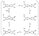
- FIG. 2 is a conceptual diagram showing an example of a promotion mechanism for the reduction reaction of water presumed in the hydrogen production cocatalyst of the present invention.
- FIG. 3A is a diagram showing examples of aromatic groups that can be possessed by the metal organic framework contained in the hydrogen production cocatalyst of the present invention.
- FIG. 3B is a diagram showing examples of ligands that the metal-organic framework contained in the hydrogen-producing cocatalyst of the present invention may have.
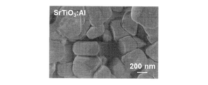
- 4A is a scanning electron microscope (SEM) observation image of SrTiO 3 :Al produced in Example 1.
- FIG. 1 is a conceptual diagram schematically showing an example of water splitting using a semiconductor material as a photocatalyst and a reaction mechanism of hydrogen generation by water splitting.
- FIG. 2 is a conceptual diagram showing an
- FIG. 4B is a SEM observation image of the NiDT produced in Example 1.
- FIG. 4C is a SEM observation image of NiDT/SrTiO 3 :Al produced in Example 1.
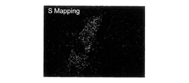
- FIG. 4D is a sulfur elemental mapping image by energy dispersive X-ray analysis (EDX) for NiDT/SrTiO 3 :Al produced in Example 1.
- FIG. 4E is a titanium elemental mapping image by EDX for NiDT/SrTiO 3 :Al produced in Example 1.
- FIG. FIG. 5 is a graph showing temporal changes in the amount of hydrogen produced when each of SrTiO 3 :Al and NiDT/SrTiO 3 :Al produced in Example 1 is used as a photocatalyst.
- FIG. 5 is a graph showing temporal changes in the amount of hydrogen produced when each of SrTiO 3 :Al and NiDT/SrTiO 3 :Al produced in Example 1 is used as a photocata
- FIG. 6 shows measurement results of linear sweep voltammetry (LSV) for SrTiO 3 :Al and NiDT/SrTiO 3 :Al produced in Example 1, respectively.
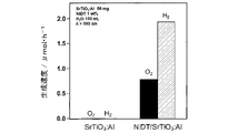
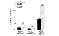
- FIG. 7 is a graph showing the generation rate of hydrogen and oxygen (gas generation rate) when SrTiO 3 :Al and NiDT/SrTiO 3 :Al prepared in Example 1 are used as photocatalysts.
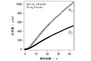
- FIG. 8 is a graph showing changes over time in the amounts of hydrogen and oxygen produced when a cycle test was performed using the NiDT/SrTiO 3 :Al produced in Example 1 as a photocatalyst.
- FIG. 7 is a graph showing the generation rate of hydrogen and oxygen (gas generation rate) when SrTiO 3 :Al and NiDT/SrTiO 3 :Al prepared in Example 1 are used as photocatalysts.
- FIG. 8 is a graph showing changes over time in the amounts of hydrogen and oxygen produced when a cycle
- FIG. 9 shows the case where the NiDT/SrTiO 3 :Al produced in Example 1 is used as a photocatalyst, and the case where the SrTiO 3 :Al produced in Example is used as a photocatalyst and an aqueous solution of nickel nitrate is added to the reaction solution.
- is a graph showing the production rate of hydrogen and oxygen in each of FIG. 10A is an SEM observation image of NiDT/SrTiO 3 :Al produced in Example after water decomposition reaction for 120 hours.
- FIG. 10B is an EDX profile of NiDT/SrTiO 3 :Al produced in Example before and after the water splitting reaction for 120 hours.
- FIG. 11 shows the generation rates of hydrogen and oxygen when each of NiDT/CoO x /SrTiO 3 :Al, CoO x /SrTiO 3 :Al and NiDT/SrTiO 3 :Al produced in Example 1 is used as a photocatalyst. It is a graph showing.
- FIG. 12 shows changes over time in the amount of hydrogen and oxygen produced when each of NiDT/CoO x /SrTiO 3 :Al and Pt/CoO x /SrTiO 3 :Al produced in Examples is used as a photocatalyst. graph.
- FIG. 12 shows changes over time in the amount of hydrogen and oxygen produced when each of NiDT/CoO x /SrTiO 3 :Al and Pt/CoO x /SrTiO 3 :Al produced in Examples is used as a photocatalyst. graph.
- FIG. 13 shows changes over time in the pressure of NiDT/SrTiO 3 :Al and Pt/SrTiO 3 :Al produced in Examples when placed in a closed system containing hydrogen and oxygen.
- FIG. 15 is a graph showing temporal changes in the amounts of hydrogen and oxygen produced when CoDT/SrTiO 3 :Al produced in Example 2 was used as a photocatalyst.
- FIG. 16 is a SEM observation image of CoDT/SrTiO 3 :Al produced in Example 2 after a water decomposition reaction for 22 hours.
- FIG. 17 is a SEM observation image of the NiDT-NCs produced in Example 3.
- FIG. 18 is a graph showing temporal changes in the amounts of hydrogen and oxygen produced when the NiDT-NCs/CoO x /SrTiO 3 :Al produced in Example 3 was used as a photocatalyst.
- FIG. 19 is a graph showing temporal changes in the amounts of hydrogen and oxygen produced when the NiDT-NCs/SrTiO 3 :Al produced in Example 3 was used as a photocatalyst.
- FIG. 20 is a graph showing the relationship between the amount of NiDT-NCs added and the gas generation rate of hydrogen and oxygen when the NiDT-NCs/SrTiO 3 :Al prepared in Example 4 is used as a photocatalyst.
- FIG. 21A is a graph showing temporal changes in the amounts of hydrogen and oxygen produced when CuCo--CAT/SrTiO 3 :Al produced in Example 5 is used as a photocatalyst.
- FIG. 21B is a graph showing temporal changes in the amount of hydrogen and oxygen produced when the CuCo-CAT/CoO x /SrTiO 3 :Al produced in Example 5 was used as a photocatalyst.
- FIG. 22 is a graph showing temporal changes in the amounts of hydrogen and oxygen produced when the CuNi-CAT/SrTiO 3 :Al produced in Example 6 was used as a photocatalyst.
- the hydrogen production co-catalyst of the present embodiment contains a metal organic framework (A) having a molecular structure represented by the following formula (1).
- M in formula (1) is at least one selected from Ni, Co, Fe, Cu, Zn, Pd, Pt, Au and Ir, L 1 to L 4 are each independently at least one selected from S, Se, Te, NH and O, C 1 and C 2 are carbon atoms forming the first aromatic group; C3 and C4 are carbon atoms forming a second aromatic group.
- the molecular structure of formula (1) typically has M as a metal nucleus, a structure containing a first aromatic group and L 1 and L 2 and a second aromatic group and L 3 and L It is a kind of complex structure in which each structure containing 4 is used as a ligand (organic ligand).
- a typical example of the molecular structure of formula (1) is a four-planar coordination structure.
- FIG. 1 schematically shows an example of water splitting using a semiconductor material as a photocatalyst and a reaction mechanism of hydrogen generation by water splitting.
- a semiconductor material 1 when a semiconductor material 1 is irradiated with light 2 having a predetermined energy or more, electrons in the valence band 12 are excited to the conduction band 13, resulting in photoexcited carriers (excited electrons (e ⁇ ) and holes (h + )) are generated.
- the generated excited electrons and holes reach the surface of the semiconductor material 1 and reduce and oxidize water, respectively, to generate hydrogen (H 2 ) and oxygen (O 2 ).
- the metal-organic structure (A) captures excited electrons that have reached the surface of the semiconductor material 1, and also causes a reduction reaction of water (more specifically, a reduction reaction of hydrogen ions (H + ) in water) on the surface. have the ability to promote
- FIG. 2 shows an example of a presumed water reduction reaction promoting mechanism in the metal-organic framework (A).
- the first aromatic group is represented by two carbon atoms corresponding to C 1 and C 2 and X 1 and X 2 and the second aromatic group is C 3 and C 4 are represented by two carbon atoms corresponding to and X 3 and X 4 .
- X 1 and X 2 together with two carbon atoms corresponding to C 1 and C 2 form the first aromatic group
- X 3 and X 4 corresponding to C 3 and C 4 together with one carbon atom forms a second aromatic group.
- the state of the metal-organic framework (A) is a state in which nothing is captured by capturing excited electrons (e ⁇ ) generated in the semiconductor material (a), so ( b) and (c), and then by capturing hydrogen ions (H + ), it changes to (d) and (e). After that, it changes in order from (e) to (f) by trapping excited electrons (e ⁇ ).
- the state (f) is reached, hydrogen is produced by reduction of the pair of trapped hydrogen ions, and the metal-organic framework (A) returns to the state (a).
- the metal-organic framework (A) that has returned to the state (a) can capture excited electrons and hydrogen ions again. Also, as shown in FIG.
- the changes in the above states are from (a) to (b), (c) . . . to (f), but not in the opposite direction.
- the reaction due to the change in state is selective, and the reverse reaction, i.e., the reduction reaction of oxygen (reaction in which water is produced from hydrogen and oxygen), is inhibited.
- the reverse reaction i.e., the reduction reaction of oxygen (reaction in which water is produced from hydrogen and oxygen)
- a co-catalyst containing the metal-organic framework (A) having reaction selectivity that inhibits the reverse reaction is suitable for further improving the efficiency of photocatalytic hydrogen production.
- M in formula (1) may be any one of Ni, Co, Fe, Cu, Zn, Pd, Pt, Au and Ir, or a combination of two or more of these metals good.
- M may be, for example, at least one selected from Ni, Co and Cu.
- M may be one type of Ni or one type of Co, or two types of a combination of Ni and Cu, or two types of a combination of Co and Cu.
- L 1 to L 4 are each independently at least one selected from S, Se, Te, NH and O.
- L 1 to L 4 may each independently be at least one selected from S, Se, Te and O, or at least one selected from S, Se and Te; It may be at least one selected from Se, may be at least one selected from S and O, may be S, and may be O.
- L 1 to L 4 may all be the same.
- Aromatic group as used herein means a group derived from an aromatic compound.
- Aromatic compounds include bicyclic, tricyclic and polycyclic compounds as well as monocyclic compounds. Two or more rings may form a fused ring.
- Aromatic compounds include heteroaromatic compounds as well as aromatic hydrocarbon compounds. Examples of heteroatoms in heteroaromatic compounds are N, O, and S.
- the aromatic compound may be a complex of a cyclic compound having aromaticity and a metal nucleus.
- aromatic compounds are benzene, triphenylene, hexaazatriphenylene, tricycloquinoazoline, porphyrin, benzoporphyrin, tetraazaporphyrin, phthalocyanine, subporphyrin, and subphthalocyanine.
- cyclic compounds that can form complexes with metal nuclei are porphyrins, benzoporphyrins, tetraazaporphyrins, phthalocyanines, subporphyrins, and subphthalocyanines.
- Subporphyrins and subphthalocyanines include benzosubporphyrins and benzosubphthalocyanines, respectively.
- At least one selected from the first aromatic group and the second aromatic group may be a group represented by the following formula (2a) or (2b).
- the group represented by formula (2a) is a hexavalent group derived from benzene.
- the group represented by formula (2b) is a hexavalent group derived from triphenylene.
- FIG. 3A Another example of a group that at least one selected from the first aromatic group and the second aromatic group can take is shown in FIG. 3A.
- R that the groups shown in FIG. 3A can take are hydrogen atoms, aliphatic groups (such as alkyl groups), and aromatic groups. R may also be a group containing heteroatoms such as a -NR'R'' group.
- the metal nucleus M are the same as the examples of M in formula (1).
- the first aromatic group and the second aromatic group may be the same or different.
- L 11 to L 16 in formula (3a) are elements that can be taken by L 1 to L 4 in formula (1) independently of each other.
- One may be a triphenylene-derived ligand represented by the following formula (3b).
- L 21 to L 26 in formula (3b) are elements independently of each other that can be taken by L 1 to L 4 in formula (1).
- FIG. 3B Another example of ligands that at least one selected from the first ligand and the second ligand can take is shown in FIG. 3B.
- R and metal core M in FIG. 3B are the same as R and metal core M in FIG. 3A, respectively.
- Each L in FIG. 3B is an element that can be taken by L 1 to L 4 in formula (1) independently of each other.
- Each L in FIG. 3B may independently be at least one selected from S, NH, O, and Se.
- the first ligand and the second ligand may be the same or different.
- the molecule of formula (1) is a bis(dithiolate)nickel structure.
- M and L in formula (1) are Co and S, respectively, and the first aromatic group and the second aromatic group are groups represented by formula (2a), the molecule of formula (1)
- the structure is a bis(dithiolate)cobalt structure.
- a metal-organic framework (A) having one or more bis(dithiolate)nickel structures and a metal-organic framework (A) having one or more bis(dithiolate)cobalt structures are referred to as , NiDT and CoDT.
- the metal organic structure (A) may contain two or more molecular structures of formula (1), or may be a polymer having the above molecular structure.
- the metal-organic framework (A), which is a polymer body, is particularly suitable for further improving the efficiency of photocatalytic hydrogen production.
- the polymer body may have a structure in which two or more metal atoms (M in Formula (1)) are linked to each other by a first ligand and/or a second ligand.
- the polymer body may have a one-dimensional structure in which the molecular structures of formula (1) are linearly bonded, or may have a two-dimensional structure in which the molecular structures are planarly bonded.
- a two-dimensional structure may be a planar structure.
- An example of the two-dimensional planar structure is shown in Equation (4) below.
- the hydrogen production co-catalyst of this embodiment may have a molecular structure represented by the following formula (4).
- the molecular structure of formula (4) is composed of a metal atom M and C 6 L 6 ligands and has a 6-fold symmetrical structure.
- the molecular structure of formula (4) has a graphene-like two-dimensional conjugated planar structure, it is particularly excellent in conductivity and chemically stable. These points can contribute to further improvement in the efficiency of hydrogen generation by photocatalyst.
- excellent electrical conductivity is advantageous for constructing a Z-Scheme (two-stage excitation energy acquisition mechanism), which will be described later.
- conductivity for example, it is possible to achieve electrical conductivity of 1.0 ⁇ 10 2 S/cm or more, and further 1.6 ⁇ 10 2 S/cm or more.
- M in formula (4) is the same as M in formula (1), ie, at least one selected from Ni, Co, Fe, Cu, Zn, Pd, Pt, Au and Ir.
- M may be, for example, one type of Ni or one type of Co, or two types of a combination of Ni and Cu, or two types of a combination of Co and Cu.
- L 11 to L 16 , L 21 to L 26 , L 31 to L 36 , L 41 to L 46 , L 51 to L 56 and L 61 to L 66 independently of each other, element.
- M is Ni
- L 11 to L 16 , L 21 to L 26 , L 31 to L 36 , L 41 to L 46 , L 51 to L 56 and L 61 to L 66 are all It is S.
- the molecular structure of formula (4a) consists of Ni and a benzenehexathiol (C 6 S 6 ) ligand.
- the metal organic framework (A) having the molecular structure of formula (4a) is a type of NiDT.
- the C 6 S 6 ligand can particularly contribute to further improving the efficiency of photocatalytic hydrogen production.
- the hydrogen production co-catalyst of the present embodiment may have a molecular structure represented by the following formula (4b).
- the molecular structure of formula (4b) is composed of a metal atom M and C 6 L 6 ligands and has a 6-fold symmetrical structure.
- the molecular structure of formula (4b) has a two-dimensional conjugated planar structure like graphene.
- M in formula (6) is the same as M in formula (1), ie, at least one selected from Ni, Co, Fe, Cu, Zn, Pd, Pt, Au and Ir.
- L 101 to L 106 , L 111 to L 116 , L 121 to L 126 , L 131 to L 136 , L 141 to L 146 , L 151 to L 156 and L 161 to L 166 are each independently 1 to L 4 are elements that can be taken.
- the hydrogen production co-catalyst of the present embodiment may have a molecular structure represented by the following formula (5).
- the molecular structure of formula (5) is composed of a metal atom M and a triphenylene-derived ligand, and has a six-fold symmetrical structure. Since the molecular structure of formula (5) has a graphene-like two-dimensional conjugated planar structure, it is particularly excellent in conductivity and chemically stable. These points can contribute to further improvement in the efficiency of hydrogen generation by photocatalyst.
- excellent electrical conductivity is advantageous for constructing a Z-Scheme (two-stage excitation energy acquisition mechanism), which will be described later.
- As for conductivity for example, it is possible to achieve electrical conductivity of 1.0 ⁇ 10 2 S/cm or more, and further 1.6 ⁇ 10 2 S/cm or more.
- M in formula (5) is the same as M in formula (1), ie, at least one selected from Ni, Co, Fe, Cu, Zn, Pd, Pt, Au and Ir.
- M may be, for example, one type of Ni or one type of Co, or two types of a combination of Ni and Cu, or two types of a combination of Co and Cu.
- L 211 to L 214 , L 221 to L 224 , L 231 to L 234 , L 241 to L 244 , L 251 to L 254 and L 261 to L 264 are independent of each other, and L 1 to L 4 take element.
- M is a combination of Co and Cu
- L 211 to L 214 , L 221 to L 224 , L 231 to L 234 , L 241 to L 244 , L 251 to L 254 and L 261 to L 264 are all O.
- the molecular structure of formula (5a) is composed of two types of Co and Cu combined and a ligand derived from oxytriphenylene. Ligands derived from oxytriphenylene can particularly contribute to further improving the efficiency of photocatalytic hydrogen production.
- the metal organic framework (A) having the catecholate structure of formula (5a) is referred to as CuCo-CAT.
- Each molecular structure of formulas (4), (4a), (4b), (5), and (5a) can be the minimum unit constituting the metal organic framework (A).
- the molecular structure may be further extended by bonding the above units together in the wavy line portions of formulas (4), (4a), (4b), (5), and (5a).
- the molecular structure may extend planarly and may form a nanosheet.
- the hydrogen-producing co-catalyst of the present embodiment has a metal organic structure (A); ), or a laminate in which nanosheets are laminated.
- the laminate can be sheet-like or particulate-like.
- the thickness of one nanosheet layer is usually about 0.3 to 2.0 nm, and may be 0.5 to 1.0 nm.
- the size of a laminate in which nanosheets are laminated is, for example, 0.3 to 2000 nm, and may be 50 to 200 nm.
- the size in the in-plane direction is not limited, but considering the efficiency as a co-catalyst, the maximum length is, for example, 1 nm or more and 10 ⁇ m or less, 50 nm or more and 5 ⁇ m or less, or 100 nm or more and 2 ⁇ m or less. , 200 nm or more and 1 ⁇ m or less, or 500 nm or more and 800 nm or less.
- the size of the nanosheet and the laminate can be evaluated, for example, by image analysis of the observed image of the hydrogen-producing promoter by SEM.
- the size is the average value measured for at least 50 hydrogen-producing cocatalysts.
- the primary particle diameter of a particle can be defined as the diameter of a circle having an area equal to the area of the particle to be measured on the observed image.
- the hydrogen-producing co-catalyst of this embodiment can be used to produce hydrogen by combining it with a semiconductor catalyst that is excited by light. Hydrogen production is typically carried out by splitting water.
- the light that excites the semiconductor catalyst is, for example, light containing at least one selected from ultraviolet light, visible light, and near-infrared light.
- the light that excites the semiconductor catalyst may have a wavelength in the range of 300 nm or more and 1200 nm or less.
- the energy at the lower end of the conduction band in the semiconductor catalyst is negatively larger than the reduction potential (hydrogen-producing potential) of water.
- the energy at the lower end of the conduction band in the semiconductor catalyst is negatively larger than the reduction potential of water, and the energy at the upper end of the valence band is It is positively larger than the oxidation potential (oxygen evolution potential) of This example is suitable for producing not only hydrogen but also oxygen by splitting water by irradiation with light.
- Examples of semiconductor catalysts are SrTiO3 , K2Ti6O13 , TiO2 , Nb2O5 , KTaO3 /KNbO3 solid solution, ZnO, ZrO2 , GaP, GaN, Si, CdS , CdSe and C3N4 . and at least one selected from these metal dopes.
- the energy at the bottom of the conduction band in each of the above examples is negatively larger than the reduction potential of water.
- the semiconductor catalyst may be at least one selected from SrTiO 3 , KTiO 3 , KTaNbO, ZrO 2 , GaP, CdS, CdSe and C 3 N 4 and metal dopes thereof. It may be at least one selected from the body. Examples of doped metals are Al, Ga, In, Rh, Ir, Cr, Sb, La, Na and Ta.
- the semiconductor catalyst may be SrTiO 3 :Al, which is SrTiO 3 doped with Al.
- the semiconductor catalyst may be a catalyst (including a visible light responsive type) disclosed in JP-A-2017-154959, JP-A-2020-138188, and JP-A-2020-142213.
- the semiconductor catalyst is not limited to the above examples.
- the semiconductor catalyst may be particulate.
- the primary particle size of the particulate semiconductor catalyst may be, for example, 1 nm or more and 500 ⁇ m or less, 5 nm or more and 20 ⁇ m or less, and further 10 nm or more and 10 ⁇ m or less.
- the primary particle size of the semiconductor catalyst can be evaluated, for example, by image analysis of the observed image of the semiconductor catalyst by SEM.
- the primary particle size is the average of the values measured for at least 50 semiconductor catalysts.
- the hydrogen production co-catalyst and the semiconductor catalyst of the present embodiment can be combined, for example, by mixing the two. Further, by synthesizing the hydrogen-producing cocatalyst in the presence of the semiconductor catalyst and attaching the produced hydrogen-producing co-catalyst to the surface of the semiconductor catalyst, the hydrogen-producing cocatalyst and the semiconductor catalyst can be combined. .
- the hydrogen-producing co-catalyst of the present embodiment may be combined with an oxygen-producing co-catalyst in addition to the semiconductor catalyst.
- oxygen-producing promoters include metals such as Mg, Ti, Mn, Fe, Co, Ni, Cu, Ga, Ru, Rh, Pd, Ag, Cd, In, Ce, Ta, W, Ir, Pt and Pb. , and oxides and composite oxides thereof.
- Preferred examples of the oxygen-producing cocatalyst are Mn, Co, Ni, Ru, Rh and Ir, and their oxides and composite oxides, and more preferred examples are Ir, MnO x , CoO x , NiCoO x and RuO. x , RhO x and IrO x .
- a photocatalyst that combines a hydrogen production cocatalyst and a semiconductor catalyst can be used, for example, for the production of hydrogen and the decomposition of water.
- first photocatalyst photocatalyst
- second photocatalyst photocatalyst
- hydrogen is generated by the first photocatalyst
- oxygen is generated by the second photocatalyst.
- You may construct a Z-Scheme that generates Z-Scheme is particularly suitable for efficient use of low-energy light such as visible light, and for increasing the degree of freedom in selecting semiconductor catalysts and designing photocatalysts.
- a photocatalyst that combines a hydrogen-producing co-catalyst, an oxygen-producing co-catalyst, and a semiconductor catalyst can be used, for example, for the production of hydrogen and oxygen and the decomposition of water.
- the method and mode of using the photocatalyst containing the hydrogen production cocatalyst of the present embodiment are not limited to the above examples.
- the hydrogen generation cocatalyst of the present embodiment includes, for example, a first solution containing metal atoms M (typically contained as ions) and a second solution containing organic ligands and incompatible with the first solution.
- a first solution containing metal atoms M typically contained as ions
- a second solution containing organic ligands and incompatible with the first solution can be formed by a liquid-liquid interfacial synthesis method in which a complex formation reaction proceeds at the interface between the solution of
- a second solution containing an organic ligand is dropped onto the surface of a first solution containing metal atoms M (typically contained as ions), and a second It may be formed by a gas-liquid interfacial synthesis method in which a complex formation reaction proceeds on the surface of the first solution while evaporating the solvent of the solution.
- the first solution and the second solution in the liquid-liquid interfacial synthesis method and the gas-liquid interfacial synthesis method are, for example, an aqueous solution and an organic solution, respectively.
- a sheet in which nanosheets of the metal organic framework (A) are laminated is usually obtained.
- the gas-liquid interfacial synthesis method it is also possible to obtain single-layer nanosheets of the metal-organic framework (A).
- the photocatalyst of this embodiment includes a semiconductor catalyst that is excited by light and the hydrogen production co-catalyst of this embodiment. Examples of hydrogen-producing cocatalysts and semiconducting catalysts, as well as methods and embodiments of the use of photocatalysts, including preferred examples, are described above.
- the amount of the hydrogen production promoter contained in the photocatalyst is, for example, 1 part by weight or less, 0.5 parts by weight or less, 0.1 parts by weight or less, 0.01 parts by weight or less, with respect to 100 parts by weight of the semiconductor catalyst. Furthermore, it may be 0.001 part by weight or less.
- the lower limit of the amount of the hydrogen-producing co-catalyst is, for example, 0.00001 parts by weight or more with respect to 100 parts by weight of the semiconductor catalyst.
- the hydrogen production co-catalyst is usually in contact with the semiconductor catalyst.
- the hydrogen-producing promoter and the semiconductor catalyst may be bonded together.
- the hydrogen-producing co-catalyst may be carried on a semiconductor catalyst.
- the photocatalyst may have a configuration in which fine hydrogen-producing co-catalysts are carried on a granular semiconductor catalyst.
- the hydrogen production co-catalyst may be sheet-like (flake-like) or amorphous colloidal particles.
- the oxygen-generating co-catalyst is usually in contact with the semiconductor catalyst.
- the oxygen-producing cocatalyst and the semiconductor catalyst may be bonded together.
- the oxygen-generating co-catalyst and the semiconductor catalyst can be bonded by a known method such as an impregnation method or a photoelectrodeposition method.
- the amount of the oxygen-generating co-catalyst that can be contained in the photocatalyst is, for example, 0.001 to 1 part by weight, and may be 0.005 to 0.5 part by weight, with respect to 100 parts by weight of the semiconductor catalyst.
- the photocatalyst is, for example, particulate.
- the shape of the photocatalyst is not limited to the above examples.
- the photocatalyst of this embodiment can be formed, for example, by mixing the hydrogen-producing promoter of this embodiment and a semiconductor catalyst. Mixing may be carried out in a solution such as an aqueous solution. In one example of mixing in a solution, a photocatalyst is obtained by mixing a particulate photocatalyst with a solution in which a sheet-like and/or particulate hydrogen-producing cocatalyst is dispersed, and then removing the solvent from the solution.
- the dispersed solution may be a nanocolloidal solution.
- the photocatalyst of this embodiment can be used, for example, to generate hydrogen by splitting water.
- the use of the photocatalyst is not limited to the above examples.
- the present invention provides a semiconductor excited by light; and a metal organic framework (A) having a molecular structure represented by the following formula (1), semiconductor materials, I will provide a.
- M in formula (1) is at least one selected from Ni, Co, Fe, Cu, Zn, Pd, Pt, Au and Ir, L 1 to L 4 are each independently at least one selected from S, Se, Te, NH and O, C 1 and C 2 are carbon atoms forming the first aromatic group; C3 and C4 are carbon atoms forming a second aromatic group.
- hydrogen can be produced using the hydrogen production promoter of the present embodiment or the photocatalyst of the present embodiment.
- the present invention provides a method for producing hydrogen, including obtaining hydrogen using the hydrogen production cocatalyst of the present embodiment or the photocatalyst of the present embodiment.
- the present invention also discloses a hydrogen production apparatus comprising a reaction section containing the hydrogen production co-catalyst of the present embodiment or the photocatalyst of the present embodiment.
- An example of a method for producing hydrogen includes irradiating the photocatalyst of the present embodiment with ultraviolet light and/or visible light to decompose water and obtain hydrogen.
- water decomposition For example, water can be decomposed using the hydrogen production promoter of the present embodiment or the photocatalyst of the present embodiment.
- the present invention provides a method for decomposing water, which includes decomposing water using the hydrogen production promoter of the present embodiment or the photocatalyst of the present embodiment.
- the present invention also discloses a hydrogen production apparatus (water decomposition apparatus) including a reaction section containing the hydrogen generation co-catalyst of the present embodiment or the photocatalyst of the present embodiment.
- hydrogen may be obtained alone, or hydrogen and oxygen may be obtained.
- Examples of embodiments in which a photocatalyst is used in each of the methods and apparatuses described above include an embodiment in which photocatalyst particles are dispersed in a solution containing water (the solution may be water), and a molded body in which photocatalyst particles are solidified in a solution. and a mode in which a composite having a photocatalyst layer containing a photocatalyst (for example, a laminate of a photocatalyst layer and a substrate) is placed in a solution.
- the aqueous solution may contain a sacrificial reducing agent. Methanol, for example, can be used as the sacrificial reducing agent.
- the amount of the sacrificial reducing agent added is not particularly limited, and is, for example, in the range of more than 0% by volume and less than 100% by volume.
- the mode of using the photocatalyst is not limited to the above examples.
- the hydrogen production device water decomposition device
- the reaction section may be a container that can accommodate each of the above solutions and that has an opening or a window that allows light to be applied to the accommodated solution.
- a molded body in which photocatalyst particles are hardened can be formed, for example, by sintering the particles or binding the particles using a binder such as a resin binder.
- a resin having excellent binding properties such as a fluororesin may be used as the resin binder.
- the photocatalyst layer containing a photocatalyst may be the molded article described above.
- substrates to be combined with the photocatalyst layer are metal substrates such as stainless steel substrates and aluminum substrates, and glass substrates.
- the electrode may be constructed by laminating the photocatalyst layer and the conductive layer. According to the electrode including the photocatalyst layer, the generation of hydrogen and the decomposition of water can be further promoted by applying a bias voltage in addition to light irradiation.
- conductive layers are layers containing conductive particles such as carbon particles and metal particles, and conductive sheets such as carbon sheets and metal sheets.
- the electrode can be formed by, for example, forming a coating film containing photocatalyst particles on the surface of the conductive layer and then drying and/or sintering the coating film.
- the generation of hydrogen and the decomposition of water by the photocatalyst of this embodiment may be performed without applying a bias voltage, in other words, without forming electrodes.
- the manufacturing apparatus may be equipped with members other than the reaction section.
- members such as other members are a collecting part such as a tank for collecting the generated hydrogen and/or oxygen, a light source for irradiating the solution, and a water supply part for supplying water to the reaction part.
- light sources are lamps capable of emitting light similar to sunlight, such as xenon lamps and metal halide lamps, mercury lamps, and LEDs.
- the manufacturing apparatus may include optical members such as windows and mirrors that allow sunlight to pass therethrough and lead it to the reaction section.
- Example 1 NiDT having a two-dimensional conjugated planar structure represented by the formulas (4) and (4a) was produced as a hydrogen generation co-catalyst, and hydrogen generation ability and water resolution when combined with a semiconductor catalyst were evaluated. .
- SrTiO 3 synthesized by a solid phase method was doped with Al by a molten salt method to prepare SrTiO 3 :Al. Specifically, it is as follows. Dry SrCO3 powder (1.48 g, 0.01 mol) and TiO2 powder ( 0.799 g, 0.01 mol) were mixed using an agate mortar for 15 min. The mixed powder was placed in an alumina crucible and fired in an electric furnace at 1373 K for 10 hours to obtain SrTiO 3 powder as a precursor. The formation of SrTiO 3 was confirmed by X-ray diffraction.
- the obtained SrTiO 3 powder, SrCl 2.6H 2 O powder, and Al 2 O 3 powder were mixed at a mixing ratio (molar ratio) of 1 :10:0.02. Mix for a minute.
- the mixed powder was placed in an alumina crucible and fired in an electric furnace at 1373K for 10 hours to obtain SrTiO 3 :Al powder.
- the resulting powder was washed with Milli-Q water (400 mL) three times and then dried overnight in a vacuum dryer.
- a xenon lamp 300 W output, wavelength ⁇ >300 nm was used as the light source, and the irradiation time was 2 hours.
- the powder after light irradiation was washed with Milli-Q water (400 mL) and ethanol (50 mL) three times each, and then dried overnight in a vacuum dryer.
- SrTiO 3 :Al after carrying CoO x is hereinafter referred to as CoO x /SrTiO 3 :Al.
- NiDT was supported on SrTiO 3 :Al and CoO x /SrTiO 3 :Al by an impregnation method. Specifically, it is as follows. SrTiO 3 :Al (or CoO x /SrTiO 3 :Al) was placed in an evaporating dish and an ethanol dispersion of NiDT (NiDT content 1% by weight) was added to it.
- NiDT/SrTiO 3 :Al a sample in which only NiDT is supported on SrTiO 3 :Al
- NiDT/CoO x /SrTiO 3 :Al a sample in which NiDT and CoO x are co-supported on SrTiO 3 :Al
- NiDT/CoO x /SrTiO 3 :Al a sample in which NiDT and CoO x are co-supported on SrTiO 3 :Al.
- FIGS. 4D and 4E The mapping of elemental sulfur and elemental titanium to NiDT/SrTiO 3 :Al is shown in FIGS. 4D and 4E, respectively.
- FIGS. 4A to 4E in the produced NiDT/SrTiO 3 :Al, it was confirmed that sheet-like NiDT was supported on particulate SrTiO 3 :Al. In addition, NiDT was confirmed to be a laminate of nanosheets.
- FIG. 5 shows the time course of the amount of hydrogen produced when unmodified SrTiO 3 :Al and NiDT/SrTiO 3 :Al are used as photocatalysts.
- methanol was used as a sacrificial reducing agent that captures holes (h + ) generated in SrTiO 3 :Al.
- the high efficiency of methanol as a sacrificial reductant is well known to those skilled in the art.
- the LSV measurement results for unmodified SrTiO 3 :Al and NiDT/SrTiO 3 :Al are shown in FIG.
- a significant reduction in hydrogen evolution overvoltage was observed for NiDT/SrTiO 3 :Al compared to unmodified SrTiO 3 :Al.
- a decrease in hydrogen generation overvoltage means a decrease in activation energy required for hydrogen generation, in other words, it means that NiDT functions as an activation site for hydrogen generation.
- FIG. 8 shows changes over time in the amounts of hydrogen and oxygen produced when NiDT/SrTiO 3 :Al is used. As shown in FIG. 8, even if the reaction was continued for 3 cycles (120 hours), almost no decrease in the gas production rate was confirmed. At the end of the first cycle, the ratio of hydrogen to oxygen produced was about 3:1, and from this, about 47.5 ⁇ mol of holes (h + ) were not used for water oxidation. It was presumed that Since the amount was much larger than the amount of NiDT used (2.13 ⁇ mol), it was considered that the organic matter remaining on the surface of the SrTiO 3 :Al powder was oxidized.
- Ni(NO 3 ) 2 nickel nitrate
- Ni content 0.25% by weight nickel nitrate
- FIG. 9 even when Ni species (Ni 2+ ions) were added to the reaction solution, the water decomposition reaction proceeded to produce hydrogen and oxygen.
- higher activity was obtained when NiDT/SrTiO 3 :Al was used (see FIG. 9), it is unlikely that Ni species were eluted from NiDT and water decomposition was promoted.
- NiDT/CoO x /SrTiO 3 :Al and Pt/CoO x /SrTiO 3 :Al were used as photocatalysts, respectively.
- changes over time in the amounts of hydrogen and oxygen produced by water decomposition were measured.
- FIG. 12 shows the measurement results. As shown in FIG. 12, when Pt is used as a reduction cocatalyst, a high production rate of hydrogen and oxygen can be obtained in the initial stage of the reaction, but after several hours, gas production apparently stops. stopped.
- NiDT/SrTiO 3 :Al and Pt/SrTiO 3 :Al (SrTiO 3 :Al powder supporting Pt particles) as photocatalysts were placed in a reaction vessel made of Pyrex. , was carried out in the gas phase. Specifically, a reaction vessel containing a photocatalyst is connected to a closed circulation system, and then hydrogen (pressure 180 Torr) and air (pressure 450 Torr) were introduced, and changes in air pressure in the circulatory system were measured over time in the dark without light irradiation.
- FIG. 13 shows the measurement results. As shown in FIG.
- NiDT is a hydrogen production co-catalyst that also has reaction selectivity as a molecular catalyst.
- Example 2 CoDT having a two-dimensional conjugated planar structure represented by the formula (4) was produced as a hydrogen-generating co-catalyst, and the hydrogen-generating ability and water resolution when combined with a semiconductor catalyst were evaluated.
- CoDT/SrTiO 3 :Al was evaluated for water decomposition by photocatalytic reaction.
- the sample powder (0.05 g) and Milli-Q water (100 mL) to be evaluated were placed in a Pyrex side-illuminated cell, and in the same manner as described above, light containing ultraviolet light (wavelength ⁇ > 300 nm) from a xenon lamp (output 300 W).
- the gas generated by light irradiation was analyzed over time by a gas chromatograph connected to a closed circulation system.
- FIG. 15 shows changes over time in the amounts of hydrogen and oxygen produced when CoDT/SrTiO 3 :Al is used as a photocatalyst. As shown in FIG. 15, generation of hydrogen and oxygen was confirmed.
- FIG. 16 shows a SEM observation image of CoDT/SrTiO 3 :Al used in the water decomposition reaction for 22 hours. As shown in FIG. 16, no significant change was observed in the shape of CoDT.
- Example 3 In Example 3, a NiDT nanocolloid having a two-dimensional conjugated planar structure represented by formulas (4) and (4a) was prepared as a hydrogen generation catalyst, and hydrogen generation ability and water resolution when combined with a semiconductor catalyst were evaluated. evaluated.
- FIG. 17 shows an SEM observation image of the solid content filtered from the NiDT-NCs solution.
- NiDT-NCs solution prepared above (NiDT-NCs content: 1% by weight) was used instead of the ethanol dispersion of NiDT. Except for this, the loading of NiDT on SrTiO 3 :Al and CoO x /SrTiO 3 :Al in Example 1 was carried out by the impregnation method.
- NiDT-NCs/SrTiO 3 :Al a sample in which only NiDT-NCs are supported on SrTiO 3 :Al is expressed as NiDT-NCs/SrTiO 3 :Al
- NiDT-NCs and CoO x are co-supported on SrTiO 3 :Al
- NiDT-NCs/SrTiO 3 :Al and NiDT-NCs/CoO x /SrTiO 3 :Al were each evaluated for water decomposition by photocatalytic reaction.
- the sample powder (0.05 g) and Milli-Q water (100 mL) to be evaluated were placed in a Pyrex top-illuminated cell, and light containing ultraviolet light (wavelength ⁇ > 300 nm) was irradiated with a xenon lamp ( It was carried out by irradiating from an output of 300 W).
- FIG. 18 shows changes over time in the amounts of hydrogen and oxygen produced when NiDT-NCs/CoO x /SrTiO 3 :Al is used as a photocatalyst.
- FIG. 19 shows changes over time in the amount of hydrogen and oxygen produced when NiDT-NCs/SrTiO 3 :Al is used as a photocatalyst. As shown in FIGS. 18 and 19, generation of hydrogen and oxygen was confirmed.
- Example 4 In Example 4, the hydrogen generating ability and water resolution were evaluated when the amount of NiDT-NCs added to the semiconductor catalyst was changed.
- NiDT-NCs on CoO x /SrTiO 3 :Al
- the amount of the NiDT-NCs solution (containing 1% by weight of NiDT-NCs) added to CoO x /SrTiO 3 :Al was converted to the amount of NiDT-NCs in the NiDT-NCs solution relative to SrTiO 3 :Al, which was 0.00.
- Impregnation was performed in the same manner as the NiDT-NCs support on CoO x /SrTiO 3 :Al in Example 3, except that the values were adjusted to 0.25 wt%, 0.10 wt%, 0.25 wt%, and 0.50 wt%. implemented by law.
- a time-gas production amount graph was created by plotting the analysis time and the gas production amount, and the gas production rate of the gases (hydrogen and oxygen) was calculated from the obtained graph. Gas production rates are shown in FIG.
- the gas generation rate of hydrogen and oxygen when NiDT-NCs/CoO x /SrTiO 3 :Al is used as a photocatalyst is the fastest when the amount of NiDT-NCs added to SrTiO 3 :Al is 0.25 wt%. It was confirmed.
- Example 5 CuCo-CAT having a two-dimensional conjugated planar structure represented by formulas (5) and (5a) was prepared as a hydrogen generation catalyst, and hydrogen generation ability and water resolution when combined with a semiconductor catalyst were evaluated. did.
- CuCo-CAT obtained as a blackish blue precipitate was filtered off, washed with dimethylformamide, acetone and methanol, and vacuum-dried for 24 hours.
- CuCo-CAT was refined as follows. 50 mg of CuCo-CAT was dispersed in 30 mL of methanol together with 170 g of 100 ⁇ m ⁇ zirconia beads, and pulverized using a bead mill (manufactured by Aimex, Easy Nano RMB II) at 2500 rpm for 2 hours. The resulting suspension was filtered through a qualitative filter paper (2A (retained particle size: 5 ⁇ m) manufactured by ADVANTEC) to collect a filtrate containing finely divided CuCo-CAT.
- 2A quantitative filter paper manufactured by ADVANTEC
- CuCo-CAT supported on SrTiO 3 :Al and CoO x /SrTiO 3 :Al CuCo-CAT was supported on SrTiO 3 :Al and CoO x /SrTiO 3 :Al by an impregnation method. Specifically, it is as follows. SrTiO 3 :Al (or CoO x /SrTiO 3 :Al) was placed in an evaporating dish, and CuCo-CAT methanol dispersion (CuCo-CAT content 0.5% by weight) was added thereto.
- the loading of CoO x on SrTiO 3 :Al was carried out in the same manner as in the examples except that the content of Co in the aqueous solution of cobalt nitrate was changed to 0.1% by weight, and the amount of CoOx carried in terms of Co was changed to 0.1% by weight. Same as 1.
- FIG. 21A shows the temporal change in the amount of hydrogen and oxygen produced when CuCo -CAT/SrTiO 3 : Al is used as a photocatalyst.
- FIG. 21B shows changes over time in the amount of oxygen produced. As shown in FIGS. 21A and 21B, generation of hydrogen and oxygen was also confirmed in the combination of CuCo-CAT and SrTiO 3 :Al.
- Example 6 As a hydrogen generation catalyst, a CuNi-CAT having a two-dimensional conjugated planar structure represented by the formula (5) (the Co of the CuCo-CAT represented by the formula (5a) was replaced with Ni) was produced, and a semiconductor Hydrogen generation ability and water resolution when combined with a catalyst were evaluated.
- the resulting suspension was transferred to a Teflon (registered trademark) container for hydrothermal synthesis (capacity: 100 mL) and heated at 85° C. for 10 hours. After centrifuging the suspension, the CuNi-CAT-modified SrTiO 3 :Al was separated by filtration, washed five times with Milli-Q water, and vacuum-dried for 24 hours. This sample is hereinafter referred to as CuNi-CAT/SrTiO 3 :Al.
- the hydrogen-producing co-catalyst of the present invention can be used, for example, in a photoreaction device such as a hydrogen production device that produces hydrogen by light irradiation and a water decomposition device that decomposes water by light irradiation.
- a photoreaction device such as a hydrogen production device that produces hydrogen by light irradiation and a water decomposition device that decomposes water by light irradiation.
Landscapes
- Chemical & Material Sciences (AREA)
- Organic Chemistry (AREA)
- Engineering & Computer Science (AREA)
- Materials Engineering (AREA)
- Chemical Kinetics & Catalysis (AREA)
- Inorganic Chemistry (AREA)
- Health & Medical Sciences (AREA)
- General Health & Medical Sciences (AREA)
- Combustion & Propulsion (AREA)
- Catalysts (AREA)
Abstract
This hydrogen generation co-catalyst is combined with a semiconductor catalyst that is excited by light. The hydrogen generation co-catalyst includes a metal-organic framework having a molecular structure indicated in formula (1). In formula (1), M is at least one substance selected from among Ni, Co, Fe, Cu, Zn, Pd, Pt, Au, and Ir, L1 to L4 each independently represent at least one substance selected from among S, Se, Te, NH, and O, C1 and C2 are carbon atoms forming a first aromatic group, and C3 and C4 are carbon atoms forming a second aromatic group.
Description
本発明は、水素生成助触媒、光触媒、水素の製造方法、水素の製造装置、及び半導体材料に関する。
本願は、2021年6月22日に、日本に出願された特願2021-103593号に基づき優先権を主張し、その内容をここに援用する。 TECHNICAL FIELD The present invention relates to a hydrogen production cocatalyst, a photocatalyst, a method for producing hydrogen, an apparatus for producing hydrogen, and a semiconductor material.
This application claims priority based on Japanese Patent Application No. 2021-103593 filed in Japan on June 22, 2021, the contents of which are incorporated herein.
近年、石油等の化石資源に依存しないエネルギーの開発及び利用が求められており、当該エネルギーのキャリアとして水素(H2)が注目されている。しかし、現在利用されている水素の多くは天然ガスの改質によって製造されており、二酸化炭素の排出を製造に伴うことが問題視されている。一方、二酸化炭素の排出のないクリーンな水素製造法として、光により励起する半導体材料を光触媒に用いた水分解が知られている。特許文献1には、光触媒として利用可能な半導体材料が開示されている。
In recent years, there has been a demand for the development and utilization of energy that does not depend on fossil resources such as petroleum, and hydrogen (H 2 ) has attracted attention as a carrier for this energy. However, most of the hydrogen currently in use is produced by reforming natural gas, and the emission of carbon dioxide accompanying the production is regarded as a problem. On the other hand, water splitting using a semiconductor material that is excited by light as a photocatalyst is known as a clean hydrogen production method that does not emit carbon dioxide. Patent Literature 1 discloses a semiconductor material that can be used as a photocatalyst.
特許文献1には、光触媒は助触媒を備えていてもよいこと、及び水素生成反応の助触媒(水素生成助触媒)としてPt等の金属やNiOx等の金属酸化物を使用できること、が記載されている。助触媒によれば、光の照射により半導体材料に生じた励起キャリアの再結合が抑制されること、及び表面反応が促進されること等によって、光分解による水素生成効率の向上が期待される。しかし、本発明者らの検討によれば、水素生成効率の更なる向上のためには、これら従来の助触媒では未だ不十分である。
Patent Document 1 describes that the photocatalyst may be provided with a promoter, and that a metal such as Pt or a metal oxide such as NiOx can be used as a hydrogen generation reaction promoter (hydrogen generation promoter). It is The co-catalyst is expected to improve the efficiency of hydrogen generation by photodecomposition by suppressing the recombination of excited carriers generated in the semiconductor material by light irradiation and promoting the surface reaction. However, according to the studies of the present inventors, these conventional cocatalysts are still insufficient to further improve hydrogen production efficiency.
本発明は、光触媒による水素の生成効率を更に向上させることに適した、新規な水素生成助触媒を提供することを目的とする。
An object of the present invention is to provide a novel hydrogen production co-catalyst suitable for further improving the efficiency of hydrogen production by photocatalyst.
本発明は、
光により励起する半導体触媒と組み合わされる水素生成助触媒であって、
以下の式(1)により示される分子構造を有する金属有機構造体を含む、
水素生成助触媒、
を提供する。 The present invention
A hydrogen-producing cocatalyst in combination with a light-excitable semiconductor catalyst,
including a metal organic structure having a molecular structure represented by the following formula (1),
hydrogen production cocatalyst,
I will provide a.

式(1)のMは、Ni,Co,Fe,Cu,Zn,Pd,Pt,Au及びIrから選ばれる少なくとも1種であり、
L1~L4は、互いに独立して、S,Se,Te,NH及びOから選ばれる少なくとも1種であり、
C1及びC2は、第1の芳香族基を形成する炭素原子であり、
C3及びC4は、第2の芳香族基を形成する炭素原子である。 M in formula (1) is at least one selected from Ni, Co, Fe, Cu, Zn, Pd, Pt, Au and Ir,
L 1 to L 4 are each independently at least one selected from S, Se, Te, NH and O,
C 1 and C 2 are carbon atoms forming the first aromatic group;
C3 and C4 are carbon atoms forming a second aromatic group.
別の側面から見て、本発明は、
光により励起する半導体触媒と、
上記本発明の水素生成助触媒と、を含む、
光触媒、
を提供する。 Viewed from another aspect, the present invention provides
a semiconductor catalyst excited by light;
and the hydrogen generation co-catalyst of the present invention,
photocatalyst,
I will provide a.
光により励起する半導体触媒と、
上記本発明の水素生成助触媒と、を含む、
光触媒、
を提供する。 Viewed from another aspect, the present invention provides
a semiconductor catalyst excited by light;
and the hydrogen generation co-catalyst of the present invention,
photocatalyst,
I will provide a.
別の側面から見て、本発明は、
上記本発明の光触媒に紫外光、可視光及び近赤外光から選ばれる少なくとも1種を含む光を照射することにより、水を分解して水素を得ることを含む、
水素の製造方法、
を提供する。 Viewed from another aspect, the present invention provides
By irradiating the photocatalyst of the present invention with light containing at least one selected from ultraviolet light, visible light and near-infrared light, water is decomposed to obtain hydrogen.
a method for producing hydrogen,
I will provide a.
別の側面から見て、本発明は、
上記本発明の光触媒を含む反応部を備える、
水素の製造装置、
を提供する。 Viewed from another aspect, the present invention provides
Equipped with a reaction part containing the photocatalyst of the present invention,
hydrogen production equipment,
I will provide a.
上記本発明の光触媒を含む反応部を備える、
水素の製造装置、
を提供する。 Viewed from another aspect, the present invention provides
Equipped with a reaction part containing the photocatalyst of the present invention,
hydrogen production equipment,
I will provide a.
別の側面から見て、本発明は、
光により励起する半導体と、
以下の式(1)により示される分子構造を有する金属有機構造体と、を含む、
半導体材料、
を提供する。 Viewed from another aspect, the present invention provides
a semiconductor excited by light;
a metal organic framework having a molecular structure represented by the following formula (1),
semiconductor materials,
I will provide a.
光により励起する半導体と、
以下の式(1)により示される分子構造を有する金属有機構造体と、を含む、
半導体材料、
を提供する。 Viewed from another aspect, the present invention provides
a semiconductor excited by light;
a metal organic framework having a molecular structure represented by the following formula (1),
semiconductor materials,
I will provide a.

式(1)のMは、Ni,Co,Fe,Cu,Zn,Pd,Pt,Au及びIrから選ばれる少なくとも1種であり、
L1~L4は、互いに独立して、S,Se,Te,NH及びOから選ばれる少なくとも1種であり、
C1及びC2は、第1の芳香族基を形成する炭素原子であり、
C3及びC4は、第2の芳香族基を形成する炭素原子である。 M in formula (1) is at least one selected from Ni, Co, Fe, Cu, Zn, Pd, Pt, Au and Ir,
L 1 to L 4 are each independently at least one selected from S, Se, Te, NH and O,
C 1 and C 2 are carbon atoms forming the first aromatic group;
C3 and C4 are carbon atoms forming a second aromatic group.
L1~L4は、互いに独立して、S,Se,Te,NH及びOから選ばれる少なくとも1種であり、
C1及びC2は、第1の芳香族基を形成する炭素原子であり、
C3及びC4は、第2の芳香族基を形成する炭素原子である。 M in formula (1) is at least one selected from Ni, Co, Fe, Cu, Zn, Pd, Pt, Au and Ir,
L 1 to L 4 are each independently at least one selected from S, Se, Te, NH and O,
C 1 and C 2 are carbon atoms forming the first aromatic group;
C3 and C4 are carbon atoms forming a second aromatic group.
本発明によれば、光触媒による水素の生成効率を更に向上させることに適した、新規な水素生成助触媒を提供できる。
According to the present invention, it is possible to provide a novel hydrogen production co-catalyst suitable for further improving the efficiency of hydrogen production by photocatalyst.
以下、本発明の実施形態について説明する。本発明は、以下の実施形態に限定されない。
Embodiments of the present invention will be described below. The present invention is not limited to the following embodiments.
[水素生成助触媒]
本実施形態の水素生成助触媒は、以下の式(1)により示される分子構造を有する金属有機構造体(A)を含む。 [Hydrogen production promoter]
The hydrogen production co-catalyst of the present embodiment contains a metal organic framework (A) having a molecular structure represented by the following formula (1).
本実施形態の水素生成助触媒は、以下の式(1)により示される分子構造を有する金属有機構造体(A)を含む。 [Hydrogen production promoter]
The hydrogen production co-catalyst of the present embodiment contains a metal organic framework (A) having a molecular structure represented by the following formula (1).

式(1)のMは、Ni,Co,Fe,Cu,Zn,Pd,Pt,Au及びIrから選ばれる少なくとも1種であり、
L1~L4は、互いに独立して、S,Se,Te,NH及びOから選ばれる少なくとも1種であり、
C1及びC2は、第1の芳香族基を形成する炭素原子であり、
C3及びC4は、第2の芳香族基を形成する炭素原子である。 M in formula (1) is at least one selected from Ni, Co, Fe, Cu, Zn, Pd, Pt, Au and Ir,
L 1 to L 4 are each independently at least one selected from S, Se, Te, NH and O,
C 1 and C 2 are carbon atoms forming the first aromatic group;
C3 and C4 are carbon atoms forming a second aromatic group.
L1~L4は、互いに独立して、S,Se,Te,NH及びOから選ばれる少なくとも1種であり、
C1及びC2は、第1の芳香族基を形成する炭素原子であり、
C3及びC4は、第2の芳香族基を形成する炭素原子である。 M in formula (1) is at least one selected from Ni, Co, Fe, Cu, Zn, Pd, Pt, Au and Ir,
L 1 to L 4 are each independently at least one selected from S, Se, Te, NH and O,
C 1 and C 2 are carbon atoms forming the first aromatic group;
C3 and C4 are carbon atoms forming a second aromatic group.
式(1)の分子構造は、典型的には、Mを金属核とすると共に、第1の芳香族基及びL1,L2を含む構造、並びに第2の芳香族基及びL3,L4を含む構造の各々を配位子(有機配位子)とする、一種の錯体構造である。式(1)の分子構造は、典型的な例において、平面四配位構造をとる。
The molecular structure of formula (1) typically has M as a metal nucleus, a structure containing a first aromatic group and L 1 and L 2 and a second aromatic group and L 3 and L It is a kind of complex structure in which each structure containing 4 is used as a ligand (organic ligand). A typical example of the molecular structure of formula (1) is a four-planar coordination structure.
半導体材料を光触媒に用いた水分解、及び水分解による水素生成反応機構の一例を、図1に模式的に示す。図1に示すように、半導体材料1に対して所定以上のエネルギーを有する光2が照射されると、価電子帯12の電子が伝導帯13に励起されて、光励起キャリア(励起電子(e-)及び正孔(h+))が生成する。生成した励起電子及び正孔が半導体材料1の表面に達して、各々、水を還元及び酸化することで、水素(H2)及び酸素(O2)が生成する。金属有機構造体(A)は、半導体材料1の表面に到達した励起電子を捕捉すると共に、上記表面における水の還元反応(より具体的には、水中の水素イオン(H+)の還元反応)を促進させる能力を有している。
FIG. 1 schematically shows an example of water splitting using a semiconductor material as a photocatalyst and a reaction mechanism of hydrogen generation by water splitting. As shown in FIG. 1, when a semiconductor material 1 is irradiated with light 2 having a predetermined energy or more, electrons in the valence band 12 are excited to the conduction band 13, resulting in photoexcited carriers (excited electrons (e − ) and holes (h + )) are generated. The generated excited electrons and holes reach the surface of the semiconductor material 1 and reduce and oxidize water, respectively, to generate hydrogen (H 2 ) and oxygen (O 2 ). The metal-organic structure (A) captures excited electrons that have reached the surface of the semiconductor material 1, and also causes a reduction reaction of water (more specifically, a reduction reaction of hydrogen ions (H + ) in water) on the surface. have the ability to promote
金属有機構造体(A)において推定される水の還元反応の促進メカニズムの一例を、図2に示す。図2では、第1の芳香族基が、C1及びC2に相当する2つの炭素原子とX1及びX2とによって表現されると共に、第2の芳香族基が、C3及びC4に相当する2つの炭素原子とX3及びX4とによって表現されている。換言すれば、X1及びX2は、C1及びC2に相当する2つの炭素原子と共に第1の芳香族基を形成し、X3及びX4は、C3及びC4に相当する2つの炭素原子と共に第2の芳香族基を形成している。図2に示すように、半導体材料にて生成した励起電子(e-)を捕捉することによって金属有機構造体(A)の状態は、何も捕捉していない状態である(a)から、(b),(c)へと変化し、次いで水素イオン(H+)を補足することによって,(d),(e)へと変化する。その後、さらに励起電子(e-)を補足することによって、(e)から(f)へと順に変化する。状態(f)に達すると、捕捉された一対の水素イオンの還元により水素が生成して、金属有機構造体(A)の状態は(a)に戻る。状態(a)に戻った金属有機構造体(A)は、再び、励起電子及び水素イオンを捕捉することが可能となる。また、図2に示すように、上記状態の変化は、(a)から(b),(c)...を経て(f)に至る方向にのみ進行し、逆方向には進行しない。換言すれば、上記状態の変化による反応は選択的であって、逆反応である酸素の還元反応(水素及び酸素から水が生成される反応)は阻害される。金属や金属酸化物からなる水素生成助触媒では、水素の生成を阻害するほどの無視できない逆反応が生じうることが当業者に知られている。逆反応を阻害する反応選択性を持つ金属有機構造体(A)を含む助触媒は、光触媒による水素の生成効率の更なる向上に適している。
FIG. 2 shows an example of a presumed water reduction reaction promoting mechanism in the metal-organic framework (A). In FIG. 2, the first aromatic group is represented by two carbon atoms corresponding to C 1 and C 2 and X 1 and X 2 and the second aromatic group is C 3 and C 4 are represented by two carbon atoms corresponding to and X 3 and X 4 . In other words, X 1 and X 2 together with two carbon atoms corresponding to C 1 and C 2 form the first aromatic group, X 3 and X 4 corresponding to C 3 and C 4 together with one carbon atom forms a second aromatic group. As shown in FIG. 2, the state of the metal-organic framework (A) is a state in which nothing is captured by capturing excited electrons (e − ) generated in the semiconductor material (a), so ( b) and (c), and then by capturing hydrogen ions (H + ), it changes to (d) and (e). After that, it changes in order from (e) to (f) by trapping excited electrons (e − ). When the state (f) is reached, hydrogen is produced by reduction of the pair of trapped hydrogen ions, and the metal-organic framework (A) returns to the state (a). The metal-organic framework (A) that has returned to the state (a) can capture excited electrons and hydrogen ions again. Also, as shown in FIG. 2, the changes in the above states are from (a) to (b), (c) . . . to (f), but not in the opposite direction. In other words, the reaction due to the change in state is selective, and the reverse reaction, i.e., the reduction reaction of oxygen (reaction in which water is produced from hydrogen and oxygen), is inhibited. It is known to those skilled in the art that hydrogen-producing cocatalysts consisting of metals and metal oxides can undergo significant reverse reactions that inhibit the production of hydrogen. A co-catalyst containing the metal-organic framework (A) having reaction selectivity that inhibits the reverse reaction is suitable for further improving the efficiency of photocatalytic hydrogen production.
式(1)のMは、Ni,Co,Fe,Cu,Zn,Pd,Pt,Au及びIrのいずれか1種であってもよいし、これらの金属の2種以上の組み合わせであってもよい。Mは、例えば、Ni、Co及びCuから選ばれる少なくとも1種であってもよい。Mは、Niの1種もしくはCoの1種であってもよいし、NiとCuを組み合わせた2種もしくはCoとCuを組み合わせた2種であってもよい。
M in formula (1) may be any one of Ni, Co, Fe, Cu, Zn, Pd, Pt, Au and Ir, or a combination of two or more of these metals good. M may be, for example, at least one selected from Ni, Co and Cu. M may be one type of Ni or one type of Co, or two types of a combination of Ni and Cu, or two types of a combination of Co and Cu.
L1~L4は、互いに独立して、S,Se,Te,NH及びOから選ばれる少なくとも1種である。L1~L4は、互いに独立して、S,Se,Te及びOから選ばれる少なくとも1種であってもよく、S,Se及びTeから選ばれる少なくとも1種であってもよく、S及びSeから選ばれる少なくとも1種であってもよく、S及びOから選ばれる少なくとも1種であってもよく、Sであってもよく、Oであってもよい。L1~L4は、全て同一であってもよい。
L 1 to L 4 are each independently at least one selected from S, Se, Te, NH and O. L 1 to L 4 may each independently be at least one selected from S, Se, Te and O, or at least one selected from S, Se and Te; It may be at least one selected from Se, may be at least one selected from S and O, may be S, and may be O. L 1 to L 4 may all be the same.
本明細書において芳香族基とは、芳香族化合物に由来する基を意味する。芳香族化合物には、単環式の化合物だけではなく、二環式、三環式及び多環式の化合物が含まれる。2以上の環は、縮合環を形成していてもよい。芳香族化合物には、芳香族炭化水素化合物だけではなく、複素芳香族化合物が含まれる。複素芳香族化合物のヘテロ原子の例は、N、O、及びSである。芳香族化合物は、芳香族性を有する環状化合物と金属核との錯体であってもよい。芳香族化合物の例は、ベンゼン、トリフェニレン、ヘキサアザトリフェニレン、トリシクロキノアゾリン、ポルフィリン、ベンゾポルフィリン、テトラアザポルフィリン、フタロシアニン、サブポルフィリン、及びサブフタロシアニンである。金属核との錯体を形成しうる環状化合物の例は、ポルフィリン、ベンゾポルフィリン、テトラアザポルフィリン、フタロシアニン、サブポルフィリン、及びサブフタロシアニンである。サブポルフィリン及びサブフタロシアニンには、それぞれ、ベンゾサブポルフィリン及びベンゾサブフタロシアニンが含まれる。
"Aromatic group" as used herein means a group derived from an aromatic compound. Aromatic compounds include bicyclic, tricyclic and polycyclic compounds as well as monocyclic compounds. Two or more rings may form a fused ring. Aromatic compounds include heteroaromatic compounds as well as aromatic hydrocarbon compounds. Examples of heteroatoms in heteroaromatic compounds are N, O, and S. The aromatic compound may be a complex of a cyclic compound having aromaticity and a metal nucleus. Examples of aromatic compounds are benzene, triphenylene, hexaazatriphenylene, tricycloquinoazoline, porphyrin, benzoporphyrin, tetraazaporphyrin, phthalocyanine, subporphyrin, and subphthalocyanine. Examples of cyclic compounds that can form complexes with metal nuclei are porphyrins, benzoporphyrins, tetraazaporphyrins, phthalocyanines, subporphyrins, and subphthalocyanines. Subporphyrins and subphthalocyanines include benzosubporphyrins and benzosubphthalocyanines, respectively.
第1の芳香族基及び第2の芳香族基から選ばれる少なくとも1つは、以下の式(2a)または(2b)により示される基であってもよい。式(2a)により示される基は、ベンゼンに由来する6価の基である。式(2b)により示される基は、トリフェニレンに由来する6価の基である。
At least one selected from the first aromatic group and the second aromatic group may be a group represented by the following formula (2a) or (2b). The group represented by formula (2a) is a hexavalent group derived from benzene. The group represented by formula (2b) is a hexavalent group derived from triphenylene.


第1の芳香族基及び第2の芳香族基から選ばれる少なくとも1つがとりうる基の別の例を図3Aに示す。図3Aに示される基がとりうるRの例は、水素原子、脂肪族基(アルキル基等)、及び芳香族基である。Rは、-NR’R’’基等のヘテロ原子を含む基であってもよい。金属核Mの例は、式(1)のMの例と同じである。
Another example of a group that at least one selected from the first aromatic group and the second aromatic group can take is shown in FIG. 3A. Examples of R that the groups shown in FIG. 3A can take are hydrogen atoms, aliphatic groups (such as alkyl groups), and aromatic groups. R may also be a group containing heteroatoms such as a -NR'R'' group. Examples of the metal nucleus M are the same as the examples of M in formula (1).
第1の芳香族基と第2の芳香族基とは、同一であっても、互いに異なっていてもよい。
The first aromatic group and the second aromatic group may be the same or different.
第1の芳香族基及びL1,L2を含む構造を有する第1の配位子、並びに第2の芳香族基及びL3,L4を含む構造を有する第2の配位子から選ばれる少なくとも1つは、以下の式(3a)により示されるC6L6配位子であってもよい。式(3a)のL11~L16は、互いに独立して、式(1)のL1~L4がとりうる元素である。
selected from a first ligand having a structure containing a first aromatic group and L 1 and L 2 and a second ligand having a structure containing a second aromatic group and L 3 and L 4 may be a C 6 L 6 ligand represented by formula (3a) below. L 11 to L 16 in formula (3a) are elements that can be taken by L 1 to L 4 in formula (1) independently of each other.

第1の芳香族基及びL1,L2を含む構造を有する第1の配位子、並びに第2の芳香族基及びL3,L4を含む構造を有する第2の配位子から選ばれる少なくとも1つは、以下の式(3b)により示されるトリフェニレン由来の配位子であってもよい。式(3b)のL21~L26は、互いに独立して、式(1)のL1~L4がとりうる元素である。
At least a first ligand having a structure containing a first aromatic group and L 1 and L 2 and a second ligand having a structure containing a second aromatic group and L3 and L4 One may be a triphenylene-derived ligand represented by the following formula (3b). L 21 to L 26 in formula (3b) are elements independently of each other that can be taken by L 1 to L 4 in formula (1).

第1の配位子及び第2の配位子から選ばれる少なくとも1つがとりうる配位子の別の例を図3Bに示す。図3BのR及び金属核Mは、それぞれ、図3AのR及び金属核Mと同じである。図3Bの各Lは、互いに独立して、式(1)のL1~L4がとりうる元素である。図3Bの各Lは、互いに独立して、S,NH,O,及びSeから選ばれる少なくとも1種であってもよい。
Another example of ligands that at least one selected from the first ligand and the second ligand can take is shown in FIG. 3B. R and metal core M in FIG. 3B are the same as R and metal core M in FIG. 3A, respectively. Each L in FIG. 3B is an element that can be taken by L 1 to L 4 in formula (1) independently of each other. Each L in FIG. 3B may independently be at least one selected from S, NH, O, and Se.
第1の配位子と第2の配位子とは、同一であっても、互いに異なっていてもよい。
The first ligand and the second ligand may be the same or different.
式(1)のM及びLが、それぞれNi及びSであると共に、第1の芳香族基及び第2の芳香族基が式(2a)により示される基である場合、式(1)の分子構造は、ビス(ジチオラート)ニッケル構造である。式(1)のM及びLが、それぞれCo及びSであると共に、第1の芳香族基及び第2の芳香族基が式(2a)により示される基である場合、式(1)の分子構造は、ビス(ジチオラート)コバルト構造である。本明細書では、1又は2以上のビス(ジチオラート)ニッケル構造を有する金属有機構造体(A)、及び1又は2以上のビス(ジチオラート)コバルト構造を有する金属有機構造体(A)を、それぞれ、NiDT及びCoDTと記載する。
When M and L in formula (1) are Ni and S, respectively, and the first aromatic group and the second aromatic group are groups represented by formula (2a), the molecule of formula (1) The structure is a bis(dithiolate)nickel structure. When M and L in formula (1) are Co and S, respectively, and the first aromatic group and the second aromatic group are groups represented by formula (2a), the molecule of formula (1) The structure is a bis(dithiolate)cobalt structure. In this specification, a metal-organic framework (A) having one or more bis(dithiolate)nickel structures and a metal-organic framework (A) having one or more bis(dithiolate)cobalt structures are referred to as , NiDT and CoDT.
金属有機構造体(A)は、式(1)の分子構造を2以上含んでいてもよく、上記分子構造のポリマー体であってもよい。ポリマー体である金属有機構造体(A)は、光触媒による水素の生成効率の更なる向上に特に適している。ポリマー体は、2以上の金属原子(式(1)のM)が、第1の配位子及び/又は第2の配位子によって互いに連結された構造を有していてもよい。
The metal organic structure (A) may contain two or more molecular structures of formula (1), or may be a polymer having the above molecular structure. The metal-organic framework (A), which is a polymer body, is particularly suitable for further improving the efficiency of photocatalytic hydrogen production. The polymer body may have a structure in which two or more metal atoms (M in Formula (1)) are linked to each other by a first ligand and/or a second ligand.
ポリマー体は、式(1)の分子構造が線状に結合した一次元構造を有していてもよいし、面状に結合した二次元構造を有していてもよい。二次元構造は、平面構造であってもよい。二次元平面構造の一例を、以下の式(4)に示す。換言すれば、本実施形態の水素生成助触媒は、以下の式(4)により示される分子構造を有していてもよい。式(4)の分子構造は、金属原子M及びC6L6配位子から構成されると共に、6回対称構造を有している。式(4)の分子構造は、グラフェンのような(graphene-like)二次元共役平面構造を有することから、導電性に特に優れると共に、化学的に安定である。これらの点は、光触媒による水素の生成効率の更なる向上に寄与しうる。また、導電性に優れることは、後述のZ-Scheme(2段励起エネルギー獲得機構)の構築に有利である。導電性としては、例えば、1.0×10²S/cm以上、更には1.6×102S/cm以上の電気伝導度の達成も可能である。
The polymer body may have a one-dimensional structure in which the molecular structures of formula (1) are linearly bonded, or may have a two-dimensional structure in which the molecular structures are planarly bonded. A two-dimensional structure may be a planar structure. An example of the two-dimensional planar structure is shown in Equation (4) below. In other words, the hydrogen production co-catalyst of this embodiment may have a molecular structure represented by the following formula (4). The molecular structure of formula (4) is composed of a metal atom M and C 6 L 6 ligands and has a 6-fold symmetrical structure. Since the molecular structure of formula (4) has a graphene-like two-dimensional conjugated planar structure, it is particularly excellent in conductivity and chemically stable. These points can contribute to further improvement in the efficiency of hydrogen generation by photocatalyst. In addition, excellent electrical conductivity is advantageous for constructing a Z-Scheme (two-stage excitation energy acquisition mechanism), which will be described later. As for conductivity, for example, it is possible to achieve electrical conductivity of 1.0×10 2 S/cm or more, and further 1.6×10 2 S/cm or more.

式(4)のMは、前記式(1)のMと同じであり、すなわち、Ni,Co,Fe,Cu,Zn,Pd,Pt,Au及びIrから選ばれる少なくとも1種である。式(4)において、Mは、例えば、Niの1種もしくはCoの1種であってもよいし、NiとCuを組み合わせた2種もしくはCoとCuを組み合わせた2種であってもよい。L11~L16,L21~L26,L31~L36,L41~L46,L51~L56及びL61~L66は、互いに独立して、前記L1~L4がとりうる元素である。
M in formula (4) is the same as M in formula (1), ie, at least one selected from Ni, Co, Fe, Cu, Zn, Pd, Pt, Au and Ir. In formula (4), M may be, for example, one type of Ni or one type of Co, or two types of a combination of Ni and Cu, or two types of a combination of Co and Cu. L 11 to L 16 , L 21 to L 26 , L 31 to L 36 , L 41 to L 46 , L 51 to L 56 and L 61 to L 66 independently of each other, element.
式(4)の分子構造の一例を、以下の式(4a)に示す。式(4a)において、MはNiであり、L11~L16,L21~L26,L31~L36,L41~L46,L51~L56及びL61~L66は、全てSである。式(4a)の分子構造は、Niと、ベンゼンヘキサチオール(C6S6)配位子とから構成される。式(4a)の分子構造を有する金属有機構造体(A)は、NiDTの一種である。C6S6配位子は、光触媒による水素の生成効率の更なる向上に、特に寄与しうる。
An example of the molecular structure of Formula (4) is shown in Formula (4a) below. In formula (4a), M is Ni, and L 11 to L 16 , L 21 to L 26 , L 31 to L 36 , L 41 to L 46 , L 51 to L 56 and L 61 to L 66 are all It is S. The molecular structure of formula (4a) consists of Ni and a benzenehexathiol (C 6 S 6 ) ligand. The metal organic framework (A) having the molecular structure of formula (4a) is a type of NiDT. The C 6 S 6 ligand can particularly contribute to further improving the efficiency of photocatalytic hydrogen production.

二次元平面構造の別の一例を、以下の式(4b)に示す。換言すれば、本実施形態の水素生成助触媒は、以下の式(4b)により示される分子構造を有していてもよい。式(4b)の分子構造は、金属原子M及びC6L6配位子から構成されると共に、6回対称構造を有している。式(4b)の分子構造は、グラフェンのような二次元共役平面構造を有している。
Another example of the two-dimensional planar structure is shown in Equation (4b) below. In other words, the hydrogen production co-catalyst of the present embodiment may have a molecular structure represented by the following formula (4b). The molecular structure of formula (4b) is composed of a metal atom M and C 6 L 6 ligands and has a 6-fold symmetrical structure. The molecular structure of formula (4b) has a two-dimensional conjugated planar structure like graphene.

式(6)のMは、前記式(1)のMと同じであり、すなわち、Ni,Co,Fe,Cu,Zn,Pd,Pt,Au及びIrから選ばれる少なくとも1種である。L101~L106,L111~L116,L121~L126,L131~L136,L141~L146,L151~L156及びL161~L166は、互いに独立して、前記L1~L4がとりうる元素である。
M in formula (6) is the same as M in formula (1), ie, at least one selected from Ni, Co, Fe, Cu, Zn, Pd, Pt, Au and Ir. L 101 to L 106 , L 111 to L 116 , L 121 to L 126 , L 131 to L 136 , L 141 to L 146 , L 151 to L 156 and L 161 to L 166 are each independently 1 to L 4 are elements that can be taken.
本実施形態の水素生成助触媒は、以下の式(5)により示される分子構造を有していてもよい。式(5)の分子構造は、金属原子M及びトリフェニレン由来の配位子から構成されると共に、6回対称構造を有している。式(5)の分子構造は、グラフェンのような(graphene-like)二次元共役平面構造を有することから、導電性に特に優れると共に、化学的に安定である。これらの点は、光触媒による水素の生成効率の更なる向上に寄与しうる。また、導電性に優れることは、後述のZ-Scheme(2段励起エネルギー獲得機構)の構築に有利である。導電性としては、例えば、1.0×10²S/cm以上、更には1.6×102S/cm以上の電気伝導度の達成も可能である。
The hydrogen production co-catalyst of the present embodiment may have a molecular structure represented by the following formula (5). The molecular structure of formula (5) is composed of a metal atom M and a triphenylene-derived ligand, and has a six-fold symmetrical structure. Since the molecular structure of formula (5) has a graphene-like two-dimensional conjugated planar structure, it is particularly excellent in conductivity and chemically stable. These points can contribute to further improvement in the efficiency of hydrogen generation by photocatalyst. In addition, excellent electrical conductivity is advantageous for constructing a Z-Scheme (two-stage excitation energy acquisition mechanism), which will be described later. As for conductivity, for example, it is possible to achieve electrical conductivity of 1.0×10 2 S/cm or more, and further 1.6×10 2 S/cm or more.

式(5)のMは、前記式(1)のMと同じであり、すなわち、Ni,Co,Fe,Cu,Zn,Pd,Pt,Au及びIrから選ばれる少なくとも1種である。式(5)において、Mは、例えば、Niの1種もしくはCoの1種であってもよいし、NiとCuを組み合わせた2種もしくはCoとCuを組み合わせた2種であってもよい。L211~L214,L221~L224,L231~L234,L241~L244,L251~L254及びL261~L264は、互いに独立して、前記L1~L4がとりうる元素である。
M in formula (5) is the same as M in formula (1), ie, at least one selected from Ni, Co, Fe, Cu, Zn, Pd, Pt, Au and Ir. In formula (5), M may be, for example, one type of Ni or one type of Co, or two types of a combination of Ni and Cu, or two types of a combination of Co and Cu. L 211 to L 214 , L 221 to L 224 , L 231 to L 234 , L 241 to L 244 , L 251 to L 254 and L 261 to L 264 are independent of each other, and L 1 to L 4 take element.
式(5)の分子構造の一例を、以下の式(5a)に示す。式(5a)において、MはCoとCuを組み合わせた2種であり、L211~L214,L221~L224,L231~L234,L241~L244,L251~L254及びL261~L264は、全てOである。式(5a)の分子構造は、CoとCuを組み合わせた2種と、オキシトリフェニレン由来の配位子とから構成される。オキシトリフェニレン由来の配位子は、光触媒による水素の生成効率の更なる向上に、特に寄与しうる。
本明細書では、式(5a)のカテコレート構造を有する金属有機構造体(A)をCuCo-CATと記載する。 An example of the molecular structure of Formula (5) is shown in Formula (5a) below. In formula (5a), M is a combination of Co and Cu, L 211 to L 214 , L 221 to L 224 , L 231 to L 234 , L 241 to L 244 , L 251 to L 254 and L 261 to L 264 are all O. The molecular structure of formula (5a) is composed of two types of Co and Cu combined and a ligand derived from oxytriphenylene. Ligands derived from oxytriphenylene can particularly contribute to further improving the efficiency of photocatalytic hydrogen production.
In this specification, the metal organic framework (A) having the catecholate structure of formula (5a) is referred to as CuCo-CAT.

式(4)、(4a)、(4b)、(5)、(5a)の各分子構造は、金属有機構造体(A)を構成する最小の単位でありうる。式(4)、(4a)、(4b)、(5)、(5a)の波線部において上記単位が互いに結合することで、分子構造は更に延びていてもよい。分子構造は平面的に延びていてもよく、ナノシートを形成していてもよい。換言すれば、本実施形態の水素生成助触媒は、金属有機構造体(A);(式(4)、(4a)、(4b)、(5)、(5a)の各分子構造を有するものに限られない)から構成されるナノシート、又はナノシートが積層した積層体であってもよい。積層体は、シート状又は粒子状でありうる。ナノシート1層の厚みは、通常、0.3~2.0nm程度であり、0.5~1.0nmであってもよい。ナノシートが積層した積層体のサイズ(シート状である場合は厚み、粒子状である場合は一次粒子径)は、例えば0.3~2000nmであり、50~200nmであってもよい。ナノシート及びシート状の積層体について、面内方向のサイズは限定されないが、助触媒としての効率を考慮すると、最大長にして、例えば1nm以上10μm以下であり、50nm以上5μm以下、100nm以上2μm以下、200nm以上1μm以下、更には500nm以上800nm以下であってもよい。ナノシート及び積層体のサイズは、例えば、SEMによる水素生成助触媒の観察像を画像解析することで評価できる。サイズは、少なくとも50個の水素生成助触媒に対して測定した値の平均値とする。粒子の一次粒子径は、観察像上の測定対象粒子の面積に等しい面積を有する円の直径として定めることができる。
Each molecular structure of formulas (4), (4a), (4b), (5), and (5a) can be the minimum unit constituting the metal organic framework (A). The molecular structure may be further extended by bonding the above units together in the wavy line portions of formulas (4), (4a), (4b), (5), and (5a). The molecular structure may extend planarly and may form a nanosheet. In other words, the hydrogen-producing co-catalyst of the present embodiment has a metal organic structure (A); ), or a laminate in which nanosheets are laminated. The laminate can be sheet-like or particulate-like. The thickness of one nanosheet layer is usually about 0.3 to 2.0 nm, and may be 0.5 to 1.0 nm. The size of a laminate in which nanosheets are laminated (thickness in the case of sheets, primary particle size in the case of particles) is, for example, 0.3 to 2000 nm, and may be 50 to 200 nm. Regarding nanosheets and sheet-like laminates, the size in the in-plane direction is not limited, but considering the efficiency as a co-catalyst, the maximum length is, for example, 1 nm or more and 10 μm or less, 50 nm or more and 5 μm or less, or 100 nm or more and 2 μm or less. , 200 nm or more and 1 μm or less, or 500 nm or more and 800 nm or less. The size of the nanosheet and the laminate can be evaluated, for example, by image analysis of the observed image of the hydrogen-producing promoter by SEM. The size is the average value measured for at least 50 hydrogen-producing cocatalysts. The primary particle diameter of a particle can be defined as the diameter of a circle having an area equal to the area of the particle to be measured on the observed image.
本実施形態の水素生成助触媒は、光により励起する半導体触媒と組み合わせることで、水素の生成に使用できる。水素の生成は、典型的には、水の分解により行われる。
The hydrogen-producing co-catalyst of this embodiment can be used to produce hydrogen by combining it with a semiconductor catalyst that is excited by light. Hydrogen production is typically carried out by splitting water.
半導体触媒を励起させる光は、例えば、紫外光、可視光及び近赤外光から選ばれる少なくとも1種を含む光である。半導体触媒を励起させる光は、波長が300nm以上1200nm以下の範囲内にあってもよい。
The light that excites the semiconductor catalyst is, for example, light containing at least one selected from ultraviolet light, visible light, and near-infrared light. The light that excites the semiconductor catalyst may have a wavelength in the range of 300 nm or more and 1200 nm or less.
本実施形態の水素生成助触媒が組み合わされる半導体触媒の典型的な一例では、半導体触媒における伝導帯の下端のエネルギーが、水の還元電位(水素発生電位)に比べて負に大きい。
In a typical example of a semiconductor catalyst combined with the hydrogen-producing cocatalyst of the present embodiment, the energy at the lower end of the conduction band in the semiconductor catalyst is negatively larger than the reduction potential (hydrogen-producing potential) of water.
本実施形態の水素生成助触媒が組み合わされる半導体触媒の一例では、半導体触媒における伝導帯の下端のエネルギーが、水の還元電位に比べて負に大きいと共に、価電子帯の上端のエネルギーが、水の酸化電位(酸素発生電位)に比べて正に大きい。この例は、光の照射による水の分解によって、水素だけではなく酸素を共に生成させることに適している。
In an example of a semiconductor catalyst combined with the hydrogen-generating cocatalyst of the present embodiment, the energy at the lower end of the conduction band in the semiconductor catalyst is negatively larger than the reduction potential of water, and the energy at the upper end of the valence band is It is positively larger than the oxidation potential (oxygen evolution potential) of This example is suitable for producing not only hydrogen but also oxygen by splitting water by irradiation with light.
半導体触媒の例は、SrTiO3,K2Ti6O13,TiO2,Nb2O5,KTaO3/KNbO3固溶体,ZnO,ZrO2,GaP,GaN,Si,CdS,CdSe及びC3N4、並びにこれらの金属ドープ体から選ばれる少なくとも1種である。上記各例における伝導帯の下端のエネルギーは、水の還元電位に比べて負に大きい。また、SrTiO3,KTiO3,TiO2,Nb2O5,KTaNbO,ZnO,ZrO2,CdS,CdSe及びC3N4については、価電子帯の上端のエネルギーが、水の酸化電位に比べて正に大きい。半導体触媒は、SrTiO3,KTiO3,KTaNbO,ZrO2,GaP,CdS,CdSe及びC3N4、並びにこれらの金属ドープ体から選ばれる少なくとも1種であってもよく、SrTiO3及びその金属ドープ体から選ばれる少なくとも1種であってもよい。ドープされる金属の例は、Al、Ga、In、Rh、Ir、Cr、Sb、La、Na及びTaである。半導体触媒は、SrTiO3にAlがドープされたSrTiO3:Alであってもよい。
Examples of semiconductor catalysts are SrTiO3 , K2Ti6O13 , TiO2 , Nb2O5 , KTaO3 /KNbO3 solid solution, ZnO, ZrO2 , GaP, GaN, Si, CdS , CdSe and C3N4 . and at least one selected from these metal dopes. The energy at the bottom of the conduction band in each of the above examples is negatively larger than the reduction potential of water. For SrTiO 3 , KTiO 3 , TiO 2 , Nb 2 O 5 , KTaNbO, ZnO, ZrO 2 , CdS, CdSe and C 3 N 4 , the energy at the upper end of the valence band is lower than the oxidation potential of water. right big. The semiconductor catalyst may be at least one selected from SrTiO 3 , KTiO 3 , KTaNbO, ZrO 2 , GaP, CdS, CdSe and C 3 N 4 and metal dopes thereof. It may be at least one selected from the body. Examples of doped metals are Al, Ga, In, Rh, Ir, Cr, Sb, La, Na and Ta. The semiconductor catalyst may be SrTiO 3 :Al, which is SrTiO 3 doped with Al.
半導体触媒は、特開2017-154959号公報、特開2020-138188号公報、及び特開2020-142213号公報の各公報に開示の触媒(可視光応答型を含む)であってもよい。ただし、半導体触媒は、上記例に限定されない。
The semiconductor catalyst may be a catalyst (including a visible light responsive type) disclosed in JP-A-2017-154959, JP-A-2020-138188, and JP-A-2020-142213. However, the semiconductor catalyst is not limited to the above examples.
半導体触媒は、粒子状であってもよい。粒子状である半導体触媒の一次粒子径は、例えば1nm以上500μm以下であり、5nm以上20μm以下、更には10nm以上10μm以下であってもよい。半導体触媒の一次粒子径は、例えば、SEMによる半導体触媒の観察像を画像解析することで評価できる。一次粒子径は、少なくとも50個の半導体触媒に対して測定した値の平均値とする。
The semiconductor catalyst may be particulate. The primary particle size of the particulate semiconductor catalyst may be, for example, 1 nm or more and 500 μm or less, 5 nm or more and 20 μm or less, and further 10 nm or more and 10 μm or less. The primary particle size of the semiconductor catalyst can be evaluated, for example, by image analysis of the observed image of the semiconductor catalyst by SEM. The primary particle size is the average of the values measured for at least 50 semiconductor catalysts.
本実施形態の水素生成助触媒と半導体触媒とは、例えば、両者を混合することで組み合わせることができる。また、半導体触媒の存在下で、水素生成助触媒を合成して、生成した水素生成助触媒を半導体触媒の表面に付着させることによって、水素生成助触媒と半導体触媒とを複合化させることができる。本実施形態の水素生成助触媒は、半導体触媒に加えて、更に酸素生成助触媒と組み合わせてもよい。酸素生成助触媒の例は、Mg,Ti,Mn,Fe,Co,Ni,Cu,Ga,Ru,Rh,Pd,Ag,Cd,In,Ce,Ta,W,Ir,Pt及びPb等の金属、並びにこれらの酸化物及び複合酸化物である。酸素生成助触媒の好ましい例は、Mn,Co,Ni,Ru,Rh及びIr、並びにこれらの酸化物及び複合酸化物であり、より好ましい例は、Ir,MnOx,CoOx,NiCoOx,RuOx,RhOx及びIrOxである。
The hydrogen production co-catalyst and the semiconductor catalyst of the present embodiment can be combined, for example, by mixing the two. Further, by synthesizing the hydrogen-producing cocatalyst in the presence of the semiconductor catalyst and attaching the produced hydrogen-producing co-catalyst to the surface of the semiconductor catalyst, the hydrogen-producing cocatalyst and the semiconductor catalyst can be combined. . The hydrogen-producing co-catalyst of the present embodiment may be combined with an oxygen-producing co-catalyst in addition to the semiconductor catalyst. Examples of oxygen-producing promoters include metals such as Mg, Ti, Mn, Fe, Co, Ni, Cu, Ga, Ru, Rh, Pd, Ag, Cd, In, Ce, Ta, W, Ir, Pt and Pb. , and oxides and composite oxides thereof. Preferred examples of the oxygen-producing cocatalyst are Mn, Co, Ni, Ru, Rh and Ir, and their oxides and composite oxides, and more preferred examples are Ir, MnO x , CoO x , NiCoO x and RuO. x , RhO x and IrO x .
水素生成助触媒及び半導体触媒を組み合わせた光触媒は、例えば、水素の製造や水の分解に利用できる。上記光触媒(第1の光触媒)と、酸素生成助触媒及び半導体触媒を組み合わせた別の光触媒(第2の光触媒)とを用いて、第1の光触媒により水素を生成し、第2の光触媒により酸素を生成するZ-Scheme(Zスキーム)を構築してもよい。Z-Schemeは、可視光のような低いエネルギーの光の有効利用、並びに半導体触媒の選択及び光触媒の設計の自由度の向上に、特に適している。
A photocatalyst that combines a hydrogen production cocatalyst and a semiconductor catalyst can be used, for example, for the production of hydrogen and the decomposition of water. Using the photocatalyst (first photocatalyst) and another photocatalyst (second photocatalyst) that is a combination of an oxygen-generating cocatalyst and a semiconductor catalyst, hydrogen is generated by the first photocatalyst, and oxygen is generated by the second photocatalyst. You may construct a Z-Scheme that generates Z-Scheme is particularly suitable for efficient use of low-energy light such as visible light, and for increasing the degree of freedom in selecting semiconductor catalysts and designing photocatalysts.
水素生成助触媒、酸素生成助触媒及び半導体触媒を組み合わせた光触媒は、例えば、水素及び酸素の製造や水の分解に利用できる。
A photocatalyst that combines a hydrogen-producing co-catalyst, an oxygen-producing co-catalyst, and a semiconductor catalyst can be used, for example, for the production of hydrogen and oxygen and the decomposition of water.
本実施形態の水素生成助触媒を含む光触媒の使用の方法及び態様は、上記例に限定されない。
The method and mode of using the photocatalyst containing the hydrogen production cocatalyst of the present embodiment are not limited to the above examples.
本実施形態の水素生成助触媒は、例えば、金属原子Mを含む(典型的にはイオンとして含む)第1の溶液と、有機配位子を含むと共に第1の溶液とは相溶しない第2の溶液と、の界面において錯体形成反応を進行させる液液界面合成法により形成できる。また、水素生成助触媒の種類によっては、金属原子Mを含む(典型的にはイオンとして含む)第1の溶液の表面に、有機配位子を含む第2の溶液を滴下し、第2の溶液の溶媒を蒸発させながら第1の溶液の表面において錯体形成反応を進行させる気液界面合成法によって形成してもよい。液液界面合成法及び気液界面合成法における第1の溶液及び第2の溶液は、それぞれ、例えば、水溶液及び有機溶液である。液液界面合成法では、通常、金属有機構造体(A)のナノシートが積層したシートが得られる。気液界面合成法では、金属有機構造体(A)の単層ナノシートを得ることも可能である。
The hydrogen generation cocatalyst of the present embodiment includes, for example, a first solution containing metal atoms M (typically contained as ions) and a second solution containing organic ligands and incompatible with the first solution. can be formed by a liquid-liquid interfacial synthesis method in which a complex formation reaction proceeds at the interface between the solution of Further, depending on the type of hydrogen generation promoter, a second solution containing an organic ligand is dropped onto the surface of a first solution containing metal atoms M (typically contained as ions), and a second It may be formed by a gas-liquid interfacial synthesis method in which a complex formation reaction proceeds on the surface of the first solution while evaporating the solvent of the solution. The first solution and the second solution in the liquid-liquid interfacial synthesis method and the gas-liquid interfacial synthesis method are, for example, an aqueous solution and an organic solution, respectively. In the liquid-liquid interfacial synthesis method, a sheet in which nanosheets of the metal organic framework (A) are laminated is usually obtained. In the gas-liquid interfacial synthesis method, it is also possible to obtain single-layer nanosheets of the metal-organic framework (A).
[光触媒]
本実施形態の光触媒は、光により励起する半導体触媒と、本実施形態の水素生成助触媒とを含む。水素生成助触媒及び半導体触媒の例、並びに光触媒の使用の方法及び態様の例は、好ましい例を含め、上述のとおりである。 [photocatalyst]
The photocatalyst of this embodiment includes a semiconductor catalyst that is excited by light and the hydrogen production co-catalyst of this embodiment. Examples of hydrogen-producing cocatalysts and semiconducting catalysts, as well as methods and embodiments of the use of photocatalysts, including preferred examples, are described above.
光触媒に含まれる水素生成助触媒の量は、半導体触媒100重量部に対して、例えば1重量部以下であり、0.5重量部以下、0.1重量部以下、0.01重量部以下、更には0.001重量部以下であってもよい。水素生成助触媒の量の下限は、半導体触媒100重量部に対して、例えば、0.00001重量部以上である。
The amount of the hydrogen production promoter contained in the photocatalyst is, for example, 1 part by weight or less, 0.5 parts by weight or less, 0.1 parts by weight or less, 0.01 parts by weight or less, with respect to 100 parts by weight of the semiconductor catalyst. Furthermore, it may be 0.001 part by weight or less. The lower limit of the amount of the hydrogen-producing co-catalyst is, for example, 0.00001 parts by weight or more with respect to 100 parts by weight of the semiconductor catalyst.
光触媒において水素生成助触媒は、通常、半導体触媒と接触している。水素生成助触媒と半導体触媒とは、接合されていてもよい。また、水素生成助触媒は、半導体触媒に担持されていてもよい。例えば、光触媒は、粒状の半導体触媒に微細な水素生成助触媒が担持された構成であってもよい。水素生成助触媒は、シート状(薄片状)であってもよいし、不定形なコロイド粒子であってもよい。
In the photocatalyst, the hydrogen production co-catalyst is usually in contact with the semiconductor catalyst. The hydrogen-producing promoter and the semiconductor catalyst may be bonded together. Further, the hydrogen-producing co-catalyst may be carried on a semiconductor catalyst. For example, the photocatalyst may have a configuration in which fine hydrogen-producing co-catalysts are carried on a granular semiconductor catalyst. The hydrogen production co-catalyst may be sheet-like (flake-like) or amorphous colloidal particles.
酸素生成助触媒を更に含む場合、酸素生成助触媒は、通常、半導体触媒と接触している。酸素生成助触媒と半導体触媒とは、接合されていてもよい。酸素生成助触媒と半導体触媒とは、例えば、含浸法や光電着法等の公知の手法により接合できる。
When the oxygen-generating co-catalyst is further included, the oxygen-generating co-catalyst is usually in contact with the semiconductor catalyst. The oxygen-producing cocatalyst and the semiconductor catalyst may be bonded together. The oxygen-generating co-catalyst and the semiconductor catalyst can be bonded by a known method such as an impregnation method or a photoelectrodeposition method.
光触媒に含まれうる酸素生成助触媒の量は、半導体触媒100重量部に対して、例えば0.001~1重量部であり、0.005~0.5重量部であってもよい。
The amount of the oxygen-generating co-catalyst that can be contained in the photocatalyst is, for example, 0.001 to 1 part by weight, and may be 0.005 to 0.5 part by weight, with respect to 100 parts by weight of the semiconductor catalyst.
光触媒は、例えば、粒子状である。ただし、光触媒の形状は、上記例に限定されない。
The photocatalyst is, for example, particulate. However, the shape of the photocatalyst is not limited to the above examples.
本実施形態の光触媒は、例えば、本実施形態の水素生成助触媒と半導体触媒とを混合して形成できる。混合は、水溶液等の溶液中で実施してもよい。溶液中での混合の一例では、シート状及び/又は粒子状の水素生成助触媒が分散した溶液に粒子状の光触媒を混合した後、溶液の溶媒を取り除いて光触媒を得る。分散した溶液は、ナノコロイド溶液であってもよい。
The photocatalyst of this embodiment can be formed, for example, by mixing the hydrogen-producing promoter of this embodiment and a semiconductor catalyst. Mixing may be carried out in a solution such as an aqueous solution. In one example of mixing in a solution, a photocatalyst is obtained by mixing a particulate photocatalyst with a solution in which a sheet-like and/or particulate hydrogen-producing cocatalyst is dispersed, and then removing the solvent from the solution. The dispersed solution may be a nanocolloidal solution.
本実施形態の光触媒は、例えば、水の分解による水素の生成に使用できる。ただし、光触媒の用途は、上記例に限定されない。用途が限定されない側面から見て、本発明は、
光により励起する半導体と、
以下の式(1)により示される分子構造を有する金属有機構造体(A)と、を含む、
半導体材料、
を提供する。 The photocatalyst of this embodiment can be used, for example, to generate hydrogen by splitting water. However, the use of the photocatalyst is not limited to the above examples. From a non-limiting aspect, the present invention provides
a semiconductor excited by light;
and a metal organic framework (A) having a molecular structure represented by the following formula (1),
semiconductor materials,
I will provide a.

式(1)のMは、Ni,Co,Fe,Cu,Zn,Pd,Pt,Au及びIrから選ばれる少なくとも1種であり、
L1~L4は、互いに独立して、S,Se,Te,NH及びOから選ばれる少なくとも1種であり、
C1及びC2は、第1の芳香族基を形成する炭素原子であり、
C3及びC4は、第2の芳香族基を形成する炭素原子である。 M in formula (1) is at least one selected from Ni, Co, Fe, Cu, Zn, Pd, Pt, Au and Ir,
L 1 to L 4 are each independently at least one selected from S, Se, Te, NH and O,
C 1 and C 2 are carbon atoms forming the first aromatic group;
C3 and C4 are carbon atoms forming a second aromatic group.
L1~L4は、互いに独立して、S,Se,Te,NH及びOから選ばれる少なくとも1種であり、
C1及びC2は、第1の芳香族基を形成する炭素原子であり、
C3及びC4は、第2の芳香族基を形成する炭素原子である。 M in formula (1) is at least one selected from Ni, Co, Fe, Cu, Zn, Pd, Pt, Au and Ir,
L 1 to L 4 are each independently at least one selected from S, Se, Te, NH and O,
C 1 and C 2 are carbon atoms forming the first aromatic group;
C3 and C4 are carbon atoms forming a second aromatic group.
[水素生成助触媒及び光触媒の応用]
以下、本実施形態の水素生成助触媒及び光触媒の応用例を説明する。ただし、水素生成助触媒及び光触媒の応用の態様は、以下の例に限定されない。 [Application of hydrogen production cocatalyst and photocatalyst]
Application examples of the hydrogen production cocatalyst and photocatalyst of the present embodiment will be described below. However, the mode of application of the hydrogen production cocatalyst and photocatalyst is not limited to the following examples.
(水素の製造)
本実施形態の水素生成助触媒、又は本実施形態の光触媒を用いて、例えば、水素を製造できる。この側面から、本発明は、本実施形態の水素生成助触媒、又は本実施形態の光触媒を用いて水素を得ることを含む、水素の製造方法を提供する。また、上記側面から、本発明は、本実施形態の水素生成助触媒、又は本実施形態の光触媒を含む反応部を備える、水素の製造装置を開示する。水素の製造方法の一例は、本実施形態の光触媒に紫外光及び/又は可視光を照射することにより、水を分解して水素を得ることを含む。 (Production of hydrogen)
For example, hydrogen can be produced using the hydrogen production promoter of the present embodiment or the photocatalyst of the present embodiment. From this aspect, the present invention provides a method for producing hydrogen, including obtaining hydrogen using the hydrogen production cocatalyst of the present embodiment or the photocatalyst of the present embodiment. In view of the above aspect, the present invention also discloses a hydrogen production apparatus comprising a reaction section containing the hydrogen production co-catalyst of the present embodiment or the photocatalyst of the present embodiment. An example of a method for producing hydrogen includes irradiating the photocatalyst of the present embodiment with ultraviolet light and/or visible light to decompose water and obtain hydrogen.
(水の分解)
本実施形態の水素生成助触媒、又は本実施形態の光触媒を用いて、例えば、水を分解できる。この側面から、本発明は、本実施形態の水素生成助触媒、又は本実施形態の光触媒を用いて水を分解することを含む、水の分解方法を提供する。また、上記側面から、本発明は、本実施形態の水素生成助触媒、又は本実施形態の光触媒を含む反応部を備える、水素の製造装置(水の分解装置)を開示する。上記水の分解方法及び水素の製造装置では、水素を単独で、又は水素及び酸素を得てもよい。 (water decomposition)
For example, water can be decomposed using the hydrogen production promoter of the present embodiment or the photocatalyst of the present embodiment. From this aspect, the present invention provides a method for decomposing water, which includes decomposing water using the hydrogen production promoter of the present embodiment or the photocatalyst of the present embodiment. In view of the above aspects, the present invention also discloses a hydrogen production apparatus (water decomposition apparatus) including a reaction section containing the hydrogen generation co-catalyst of the present embodiment or the photocatalyst of the present embodiment. In the above water decomposition method and hydrogen production apparatus, hydrogen may be obtained alone, or hydrogen and oxygen may be obtained.
上記各方法及び装置において光触媒を使用する態様の例は、水を含む溶液中(溶液は、水であってもよい)に光触媒の粒子を分散させる態様、光触媒の粒子を固めた成形体を溶液中に配置する態様、及び光触媒を含む光触媒層を備えた複合体(例えば、光触媒層と基材との積層体)を溶液中に配置する態様である。水を含む溶液は、犠牲還元剤を含んでいてもよい。犠牲還元剤としては、例えば、メタノールを用いることができる。犠牲還元剤の添加量は、特に制限はなく、例えば、0体積%を超え、100体積%未満の範囲内である。ただし、光触媒を使用する態様は、上記例に限定されない。水素の製造装置(水の分解装置)は、光触媒の粒子が分散した溶液、光触媒を含む成形体が配置された溶液、又は光触媒層を備えた複合体が配置された溶液が収容された反応部を備えていてもよい。反応部は、上記各溶液が収容されうると共に、収容された溶液に対して光を照射可能な開口や窓を有する容器であってもよい。
Examples of embodiments in which a photocatalyst is used in each of the methods and apparatuses described above include an embodiment in which photocatalyst particles are dispersed in a solution containing water (the solution may be water), and a molded body in which photocatalyst particles are solidified in a solution. and a mode in which a composite having a photocatalyst layer containing a photocatalyst (for example, a laminate of a photocatalyst layer and a substrate) is placed in a solution. The aqueous solution may contain a sacrificial reducing agent. Methanol, for example, can be used as the sacrificial reducing agent. The amount of the sacrificial reducing agent added is not particularly limited, and is, for example, in the range of more than 0% by volume and less than 100% by volume. However, the mode of using the photocatalyst is not limited to the above examples. The hydrogen production device (water decomposition device) is a reaction part containing a solution in which photocatalyst particles are dispersed, a solution in which a molded body containing a photocatalyst is arranged, or a solution in which a composite with a photocatalyst layer is arranged. may be provided. The reaction section may be a container that can accommodate each of the above solutions and that has an opening or a window that allows light to be applied to the accommodated solution.
光触媒の粒子を固めた成形体は、例えば、粒子を焼結させたり、樹脂バインダー等の結着剤を用いて粒子を結着させたりすることで形成できる。樹脂バインダーには、フッ素樹脂等の結着性に優れる樹脂を使用してもよい。光触媒を含む光触媒層は、上記成形体であってもよい。光触媒層と組み合わせる基材の例は、ステンレス基材及びアルミ基材等の金属基材、並びにガラス基材である。
A molded body in which photocatalyst particles are hardened can be formed, for example, by sintering the particles or binding the particles using a binder such as a resin binder. A resin having excellent binding properties such as a fluororesin may be used as the resin binder. The photocatalyst layer containing a photocatalyst may be the molded article described above. Examples of substrates to be combined with the photocatalyst layer are metal substrates such as stainless steel substrates and aluminum substrates, and glass substrates.
光触媒層と導電層とを積層して電極を構成してもよい。光触媒層を含む電極によれば、光の照射に加えてバイアス電圧を印加することで、水素の生成や水の分解を更に促進できる。導電層の例は、カーボン粒子及び金属粒子等の導電性粒子を含む層、並びにカーボンシート及び金属シート等の導電性シートである。電極は、例えば、光触媒の粒子を含む塗布膜を導電層の表面に形成した後、塗布膜を乾燥及び/又は焼結して形成できる。ただし、本実施形態の光触媒による水素の生成及び水の分解は、バイアス電圧を印加することなく、換言すれば、電極を構成することなく、実施してもよい。
The electrode may be constructed by laminating the photocatalyst layer and the conductive layer. According to the electrode including the photocatalyst layer, the generation of hydrogen and the decomposition of water can be further promoted by applying a bias voltage in addition to light irradiation. Examples of conductive layers are layers containing conductive particles such as carbon particles and metal particles, and conductive sheets such as carbon sheets and metal sheets. The electrode can be formed by, for example, forming a coating film containing photocatalyst particles on the surface of the conductive layer and then drying and/or sintering the coating film. However, the generation of hydrogen and the decomposition of water by the photocatalyst of this embodiment may be performed without applying a bias voltage, in other words, without forming electrodes.
製造装置は、反応部以外の他の部材を備えていてもよい。他の部材の例は、生成した水素及び/又は酸素を捕集するタンク等の捕集部、溶液に照射する光の光源、及び反応部に水を供給する給水部である。光源の例は、キセノンランプ及びメタルハライドランプ等の太陽光に近似した光を照射可能なランプ、水銀ランプ、並びにLEDである。太陽光を照射する場合、製造装置は、太陽光を透過して反応部に導く窓及びミラー等の光学部材を備えていてもよい。
The manufacturing apparatus may be equipped with members other than the reaction section. Examples of other members are a collecting part such as a tank for collecting the generated hydrogen and/or oxygen, a light source for irradiating the solution, and a water supply part for supplying water to the reaction part. Examples of light sources are lamps capable of emitting light similar to sunlight, such as xenon lamps and metal halide lamps, mercury lamps, and LEDs. In the case of irradiating sunlight, the manufacturing apparatus may include optical members such as windows and mirrors that allow sunlight to pass therethrough and lead it to the reaction section.
以下、実施例により、本発明を更に詳細に説明する。本発明は、以下に示す具体的な態様に限定されない。
The present invention will be described in more detail below with reference to examples. The present invention is not limited to the specific embodiments shown below.
[実施例1]
実施例1では、水素生成助触媒として、式(4),(4a)に示す二次元共役平面構造を有するNiDTを作製し、半導体触媒と組み合わせたときの水素発生能及び水の分解能を評価した。 [Example 1]
In Example 1, NiDT having a two-dimensional conjugated planar structure represented by the formulas (4) and (4a) was produced as a hydrogen generation co-catalyst, and hydrogen generation ability and water resolution when combined with a semiconductor catalyst were evaluated. .
(NiDTの作製)
直径12cmのシャーレにベンゼンヘキサチオール(BHT)6mgを秤量し、脱気したジクロロメタン150mLに分散させて飽和溶液とした。次に、脱気した水をジクロロメタン層の上に静かに滴下して、ジクロロメタン層の表面を水層により完全に覆った。次に、酢酸ニッケル(Ni(OAc)2)20mgが溶解した水溶液20mLを1滴ずつ、ゆっくりと水層に滴下し、混合した。その後、24時間静置したところ、ジクロロメタン層と水層との液液界面に、光沢のあるシート状のNiDTが生成した。次に、ジクロロメタン層及び水層を、それぞれ、純粋なジクロロメタン及び水で4回リンスして除去した後、残ったNiDTをエタノールに分散させた。次に、エタノールに分散したNiDTに対して、ビーズミル(Aimex社製、イージーナノRMBII、ビーズ径0.2mm)を用いて粉砕処理(回転速度2000rpm、処理時間45分)を実施し、微細なシートであるNiDTを得た。上記操作は、全て、窒素雰囲気のグローブボックスで実施した。 (Preparation of NiDT)
6 mg of benzenehexathiol (BHT) was weighed in a petri dish with a diameter of 12 cm and dispersed in 150 mL of degassed dichloromethane to obtain a saturated solution. Next, degassed water was gently dripped onto the dichloromethane layer to completely cover the surface of the dichloromethane layer with the aqueous layer. Next, 20 mL of an aqueous solution in which 20 mg of nickel acetate (Ni(OAc) 2 ) was dissolved was slowly added drop by drop to the aqueous layer and mixed. Then, when the mixture was allowed to stand for 24 hours, a glossy sheet-like NiDT was formed at the liquid-liquid interface between the dichloromethane layer and the water layer. The dichloromethane and water layers were then removed by rinsing four times with pure dichloromethane and water, respectively, after which the remaining NiDT was dispersed in ethanol. Next, the NiDT dispersed in ethanol was pulverized (rotation speed 2000 rpm, treatment time 45 minutes) using a bead mill (manufactured by Aimex, Easy Nano RMB II, bead diameter 0.2 mm) to obtain a fine sheet. NiDT was obtained. All of the above operations were performed in a glove box under a nitrogen atmosphere.
(SrTiO3:Alの作製)
Chem. Rev. 2020, 120, 8536を参考に、固相法で合成したSrTiO3に対して溶融塩法によりAlをドープして、SrTiO3:Alを作製した。具体的には、次のとおりである。乾燥したSrCO3粉末(1.48g、0.01mol)とTiO2粉末(0.799g、0.01mol)とをメノー乳鉢を用いて15分間混合した。混合した粉末をアルミナ製の坩堝に入れ、電気炉を用いて1373Kで10時間焼成して、前駆体であるSrTiO3の粉末を得た。SrTiO3の生成は、X線回折により確認した。次に、得られたSrTiO3粉末、SrCl2・6H2O粉末、及びAl2O3粉末を、1:10:0.02の混合比(モル比)で混ぜ、更に、乳鉢を用いて15分間混合した。混合した粉末をアルミナ製の坩堝に入れ、電気炉を用いて1373Kで10時間焼成して、SrTiO3:Alの粉末を得た。得られた粉末は、Milli-Q水(400mL)で3回洗浄した後、真空乾燥機で一晩乾燥させた。 (Preparation of SrTiO 3 :Al)
With reference to Chem. Rev. 2020, 120, 8536, SrTiO 3 synthesized by a solid phase method was doped with Al by a molten salt method to prepare SrTiO 3 :Al. Specifically, it is as follows. Dry SrCO3 powder (1.48 g, 0.01 mol) and TiO2 powder ( 0.799 g, 0.01 mol) were mixed using an agate mortar for 15 min. The mixed powder was placed in an alumina crucible and fired in an electric furnace at 1373 K for 10 hours to obtain SrTiO 3 powder as a precursor. The formation of SrTiO 3 was confirmed by X-ray diffraction. Next, the obtained SrTiO 3 powder, SrCl 2.6H 2 O powder, and Al 2 O 3 powder were mixed at a mixing ratio (molar ratio) of 1 :10:0.02. Mix for a minute. The mixed powder was placed in an alumina crucible and fired in an electric furnace at 1373K for 10 hours to obtain SrTiO 3 :Al powder. The resulting powder was washed with Milli-Q water (400 mL) three times and then dried overnight in a vacuum dryer.
(SrTiO3:Al粉末へのCoOx粒子の担持)
J. Phys. Chem. B 2003, 107, 7965に従い、前駆体溶液として硝酸コバルト(Co(NO3)2)水溶液(Coの含有量0.5重量%)、酸化犠牲剤としてNaIO3(0.01mol)を、それぞれ用い、光析出法により、酸素生成助触媒であるCoOx粒子をSrTiO3:Al粉末に担持させた。CoOxの担持量は、Coとして0.5重量%であった。光源にはキセノンランプ(出力300W、波長λ>300nm)を用い、照射時間は2時間とした。光照射後の粉末は、Milli-Q水(400mL)及びエタノール(50mL)で、それぞれ3回洗浄した後、真空乾燥器で一晩乾燥させた。以下、CoOxを担持させた後のSrTiO3:Alを、CoOx/SrTiO3:Alと表記する。 (SrTiO 3 : Support of CoO x particles on Al powder)
According to J. Phys. Chem. B 2003, 107, 7965, a cobalt nitrate (Co(NO 3 ) 2 ) aqueous solution (0.5% by weight of Co) was used as a precursor solution, and NaIO 3 (0.5% by weight) was used as an oxidation sacrificial agent. 01 mol), and CoO x particles, which are co-catalysts for oxygen generation, were supported on the SrTiO 3 :Al powder by a photoprecipitation method. The amount of CoOx carried was 0.5% by weight as Co. A xenon lamp (300 W output, wavelength λ>300 nm) was used as the light source, and the irradiation time was 2 hours. The powder after light irradiation was washed with Milli-Q water (400 mL) and ethanol (50 mL) three times each, and then dried overnight in a vacuum dryer. SrTiO 3 :Al after carrying CoO x is hereinafter referred to as CoO x /SrTiO 3 :Al.
(SrTiO3:Al及びCoOx/SrTiO3:AlへのNiDTの担持)
SrTiO3:Al及びCoOx/SrTiO3:AlへのNiDTの担持は、含浸法により実施した。具体的には、次のとおりである。SrTiO3:Al(又はCoOx/SrTiO3:Al)を蒸発皿にとり、NiDTのエタノール分散液(NiDTの含有量1重量%)をこれに加えた。次に、ガラス棒を用いて混合液を撹拌しながら湯浴により蒸発乾固させて、NiDTが担持されたSrTiO3:Al(又はCoOx/SrTiO3:Al)の粉末を得た。NiDTの担持量は、いずれも1重量%であった。以下、SrTiO3:AlにNiDTのみが担持されたサンプルをNiDT/SrTiO3:Alと表記し、SrTiO3:AlにNiDT及びCoOxが共担持されたサンプルをNiDT/CoOx/SrTiO3:Alと表記する。 (Supporting NiDT on SrTiO 3 :Al and CoO x /SrTiO 3 :Al)
NiDT was supported on SrTiO 3 :Al and CoO x /SrTiO 3 :Al by an impregnation method. Specifically, it is as follows. SrTiO 3 :Al (or CoO x /SrTiO 3 :Al) was placed in an evaporating dish and an ethanol dispersion of NiDT (NiDT content 1% by weight) was added to it. Next, the mixture was evaporated to dryness in a hot water bath while being stirred using a glass rod to obtain a powder of SrTiO 3 :Al (or CoO x /SrTiO 3 :Al) supporting NiDT. The amount of NiDT supported was 1% by weight in each case. Hereinafter, a sample in which only NiDT is supported on SrTiO 3 :Al is referred to as NiDT/SrTiO 3 :Al, and a sample in which NiDT and CoO x are co-supported on SrTiO 3 :Al is referred to as NiDT/CoO x /SrTiO 3 :Al. is written as
SrTiO3:Al及びCoOx/SrTiO3:AlへのNiDTの担持は、含浸法により実施した。具体的には、次のとおりである。SrTiO3:Al(又はCoOx/SrTiO3:Al)を蒸発皿にとり、NiDTのエタノール分散液(NiDTの含有量1重量%)をこれに加えた。次に、ガラス棒を用いて混合液を撹拌しながら湯浴により蒸発乾固させて、NiDTが担持されたSrTiO3:Al(又はCoOx/SrTiO3:Al)の粉末を得た。NiDTの担持量は、いずれも1重量%であった。以下、SrTiO3:AlにNiDTのみが担持されたサンプルをNiDT/SrTiO3:Alと表記し、SrTiO3:AlにNiDT及びCoOxが共担持されたサンプルをNiDT/CoOx/SrTiO3:Alと表記する。 (Supporting NiDT on SrTiO 3 :Al and CoO x /SrTiO 3 :Al)
NiDT was supported on SrTiO 3 :Al and CoO x /SrTiO 3 :Al by an impregnation method. Specifically, it is as follows. SrTiO 3 :Al (or CoO x /SrTiO 3 :Al) was placed in an evaporating dish and an ethanol dispersion of NiDT (
(SEMによるSrTiO3:Al、NiDT、及びNiDTの担持状態の確認)
SrTiO3:Al、NiDT、及びNiDT/SrTiO3:Alの形状、並びにSrTiO3:Alに対するNiDTの担持の状態を、SEM(Carl Zeiss-SII Nano Technology製、NVision40)を用いた観察、及びエネルギー分散型X線分析(EDX)を用いた元素マッピングにより確認した。SrTiO3:Al、NiDT、及びNiDT/SrTiO3:AlのSEMによる観察像を、それぞれ、図4A、図4B及び図4Cに示す。NiDT/SrTiO3:Alに対する硫黄元素及びチタン元素のマッピングを、それぞれ、図4D及び図4Eに示す。図4A~図4Eに示すように、作製したNiDT/SrTiO3:Alでは、粒子状のSrTiO3:Alにシート状のNiDTが担持されていることが確認された。また、NiDTは、ナノシートの積層体であることが確認された。 (Confirmation of supported state of SrTiO 3 :Al, NiDT, and NiDT by SEM)
The shapes of SrTiO 3 :Al, NiDT, and NiDT/SrTiO 3 :Al, and the state of NiDT supported on SrTiO 3 :Al were observed using an SEM (NVision 40, manufactured by Carl Zeiss-SII Nano Technology) and energy dispersion. Confirmed by elemental mapping using type X-ray analysis (EDX). SEM images of SrTiO 3 :Al, NiDT and NiDT/SrTiO 3 :Al are shown in FIGS. 4A, 4B and 4C, respectively. The mapping of elemental sulfur and elemental titanium to NiDT/SrTiO 3 :Al is shown in FIGS. 4D and 4E, respectively. As shown in FIGS. 4A to 4E, in the produced NiDT/SrTiO 3 :Al, it was confirmed that sheet-like NiDT was supported on particulate SrTiO 3 :Al. In addition, NiDT was confirmed to be a laminate of nanosheets.
SrTiO3:Al、NiDT、及びNiDT/SrTiO3:Alの形状、並びにSrTiO3:Alに対するNiDTの担持の状態を、SEM(Carl Zeiss-SII Nano Technology製、NVision40)を用いた観察、及びエネルギー分散型X線分析(EDX)を用いた元素マッピングにより確認した。SrTiO3:Al、NiDT、及びNiDT/SrTiO3:AlのSEMによる観察像を、それぞれ、図4A、図4B及び図4Cに示す。NiDT/SrTiO3:Alに対する硫黄元素及びチタン元素のマッピングを、それぞれ、図4D及び図4Eに示す。図4A~図4Eに示すように、作製したNiDT/SrTiO3:Alでは、粒子状のSrTiO3:Alにシート状のNiDTが担持されていることが確認された。また、NiDTは、ナノシートの積層体であることが確認された。 (Confirmation of supported state of SrTiO 3 :Al, NiDT, and NiDT by SEM)
The shapes of SrTiO 3 :Al, NiDT, and NiDT/SrTiO 3 :Al, and the state of NiDT supported on SrTiO 3 :Al were observed using an SEM (
(光触媒反応による水素生成能の評価)
未修飾のSrTiO3:Al、及びNiDT/SrTiO3:Alのそれぞれに対して、光触媒反応による水素(H2)生成能を評価した。評価は、評価対象である各粉末(0.05g)、Milli-Q水(80mL)及びメタノール(20mL)をPyrex製(ホウケイ酸ガラス製)の側方照射型セル(容量192mL)に収容し、紫外光を含む光(波長λ>300nm)をキセノンランプ(出力300W)から照射することで実施した。すなわち、各粉末、Milli-Q水及びメタノールを収容した側方照射型セルを閉鎖循環系に接続した後、磁気撹拌子と磁気攪拌機を用いて、各粉末、Milli-Q水及びメタノールを撹拌混合しながら、側方照射型セルの側面から紫外光を含む光を照射した。光の照射により生成した気体は、閉鎖循環系に接続したガスクロマトグラフにより、経時的に分析した。未修飾のSrTiO3:Al及びNiDT/SrTiO3:Alのそれぞれを光触媒として用いた場合における水素生成量の経時変化を図5に示す。なお、メタノールは、SrTiO3:Alに生成した正孔(h+)を捕捉する犠牲還元剤として使用した。犠牲還元剤としてのメタノールの効率の高さは、当業者に周知である。 (Evaluation of hydrogen generation ability by photocatalytic reaction)
Unmodified SrTiO 3 :Al and NiDT/SrTiO 3 :Al were each evaluated for hydrogen (H 2 ) generation ability by photocatalytic reaction. For the evaluation, each powder (0.05 g) to be evaluated, Milli-Q water (80 mL) and methanol (20 mL) were housed in a Pyrex (borosilicate glass) side irradiation type cell (capacity 192 mL), It was carried out by irradiating light containing ultraviolet light (wavelength λ>300 nm) from a xenon lamp (output 300 W). That is, after connecting the side irradiation type cell containing each powder, Milli-Q water and methanol to a closed circulation system, using a magnetic stirrer and a magnetic stirrer, stir and mix each powder, Milli-Q water and methanol. At the same time, light including ultraviolet light was irradiated from the side surface of the side irradiation type cell. The gas generated by light irradiation was analyzed over time by a gas chromatograph connected to a closed circulation system. FIG. 5 shows the time course of the amount of hydrogen produced when unmodified SrTiO 3 :Al and NiDT/SrTiO 3 :Al are used as photocatalysts. Note that methanol was used as a sacrificial reducing agent that captures holes (h + ) generated in SrTiO 3 :Al. The high efficiency of methanol as a sacrificial reductant is well known to those skilled in the art.
図5に示すように、未修飾のSrTiO3:Alを用いた場合、24時間の間に20μmolの水素の生成が確認された。これに対し、NiDT/SrTiO3:Alを用いた場合は、凡そ15倍の308μmolの水素の生成が確認された。換言すれば、NiDTの担持によって、水素の生成に対するSrTiO3:Alの活性が大幅に向上することが確認された。また、NiDT/SrTiO3:Alについて、24時間の反応におけるNiDT基準のターンオーバー数(TON)は145と算出された。このような大きなTONは、水素の生成がNiDTの分解ではなく水の分解に由来することを明確に示している。以上の結果から、NiDTが水素生成助触媒として機能することが確認された。
As shown in FIG. 5, when unmodified SrTiO 3 :Al was used, generation of 20 μmol of hydrogen during 24 hours was confirmed. On the other hand, when NiDT/SrTiO 3 :Al was used, it was confirmed that 308 μmol of hydrogen, which is approximately 15 times as much, was produced. In other words, it was confirmed that the loading of NiDT greatly improved the activity of SrTiO 3 :Al for hydrogen generation. Also, for NiDT/SrTiO 3 :Al, the NiDT-based turnover number (TON) was calculated to be 145 in the 24-hour reaction. Such a large TON clearly indicates that hydrogen production comes from the decomposition of water rather than the decomposition of NiDT. From the above results, it was confirmed that NiDT functions as a hydrogen production co-catalyst.
(水素発生過電圧の電気化学的測定)
未修飾のSrTiO3:Al、及びNiDT/SrTiO3:Alのそれぞれに対して、電気化学的測定により、水素発生過電圧を評価した。評価は、以下のように実施した。 (Electrochemical measurement of hydrogen generation overvoltage)
Hydrogen evolution overvoltage was evaluated by electrochemical measurements for unmodified SrTiO 3 :Al and NiDT/SrTiO 3 :Al, respectively. Evaluation was implemented as follows.
BAS製グラッシーカーボン(GC)電極に、未修飾のSrTiO3:Al又はNiDT/SrTiO3:Alのエタノール分散液(5mg/mL)を24μL滴下した後、一晩乾燥させて、作用極を作製した。次に、対極にPt線、参照極に銀・塩化銀電極、電解液にリン酸緩衝液(pH=7)を用いて、リニアスイープボルタンメトリー(LSV)測定を実施した。なお、測定を実施する前に、アルゴンガスを30分間バブリングさせて、電解液中の溶存酸素を除去した。未修飾のSrTiO3:Al及びNiDT/SrTiO3:Alのそれぞれに対するLSVの測定結果を、図6に示す。図6に示すように、NiDT/SrTiO3:Alの水素発生過電圧には、未修飾のSrTiO3:Alと比べて、顕著な低下が観測された。水素発生過電圧の低下は、水素生成に必要な活性化エネルギーの低下を意味しており、換言すれば、水素生成の活性化サイトとしてNiDTが機能したことを意味している。
24 μL of unmodified SrTiO 3 :Al or NiDT/SrTiO 3 :Al ethanol dispersion (5 mg/mL) was added dropwise to BAS glassy carbon (GC) electrode, and dried overnight to prepare a working electrode. . Next, linear sweep voltammetry (LSV) measurement was performed using a Pt wire as a counter electrode, a silver/silver chloride electrode as a reference electrode, and a phosphate buffer (pH=7) as an electrolyte. Before the measurement, argon gas was bubbled for 30 minutes to remove dissolved oxygen in the electrolytic solution. The LSV measurement results for unmodified SrTiO 3 :Al and NiDT/SrTiO 3 :Al are shown in FIG. As shown in FIG. 6, a significant reduction in hydrogen evolution overvoltage was observed for NiDT/SrTiO 3 :Al compared to unmodified SrTiO 3 :Al. A decrease in hydrogen generation overvoltage means a decrease in activation energy required for hydrogen generation, in other words, it means that NiDT functions as an activation site for hydrogen generation.
(光触媒反応による水分解能の評価)
未修飾のSrTiO3:Al、及びNiDT/SrTiO3:Alのそれぞれに対して、光触媒反応による水分解能を評価した。評価は、評価対象である各粉末(0.05g)及びMilli-Q水(100mL)をPyrex製の側方照射型セルに収容し、上記と同様に、紫外光を含む光(波長λ>300nm)をキセノンランプ(出力300W)から照射することで実施した。光の照射により生成した気体は、閉鎖循環系に接続したガスクロマトグラフにより、経時的に分析した。未修飾のSrTiO3:Al、及びNiDT/SrTiO3:Alのそれぞれを光触媒として用いた場合における水素及び酸素の生成速度を図7に示す。図7に示すように、未修飾のSrTiO3:Alを用いた場合、ほとんど気体の生成が確認されなかった。これに対して、NiDT/SrTiO3:Alを用いた場合には水の分解が進行し、水素及び酸素が、ほぼ化学量論比(2:1)で生成した。 (Evaluation of water resolution by photocatalytic reaction)
Unmodified SrTiO 3 :Al and NiDT/SrTiO 3 :Al were each evaluated for hydrolysis by photocatalysis. For the evaluation, each powder (0.05 g) and Milli-Q water (100 mL) to be evaluated were placed in a Pyrex side irradiation cell, and in the same manner as above, light containing ultraviolet light (wavelength λ > 300 nm ) was carried out by irradiation from a xenon lamp (output 300 W). The gas generated by light irradiation was analyzed over time by a gas chromatograph connected to a closed circulation system. FIG. 7 shows the production rates of hydrogen and oxygen when unmodified SrTiO 3 :Al and NiDT/SrTiO 3 :Al are used as photocatalysts. As shown in FIG. 7, when unmodified SrTiO 3 :Al was used, almost no gas was confirmed. On the other hand, when NiDT/SrTiO 3 :Al was used, decomposition of water proceeded, and hydrogen and oxygen were produced in a substantially stoichiometric ratio (2:1).
次に、40時間を1サイクルとして、上記光の照射を3サイクル実施した。各サイクルとサイクルとの間では、光の照射を一旦停止し、閉鎖循環系の内部の気体を開放した。NiDT/SrTiO3:Alを用いた場合における水素及び酸素の生成量の経時変化を図8に示す。図8に示すように、3サイクル(120時間)の反応を継続しても、気体生成速度の低下はほとんど確認されなかった。なお、1サイクル目の終了時点では、生成した水素及び酸素の比は約3:1であり、このことから、約47.5μmol相当の正孔(h+)が水の酸化には使われなかったことが推定された。その量は、使用したNiDTの物質量(2.13μmol)に比べて非常に大きいことから、SrTiO3:Al粉末の表面に残留していた有機物の酸化に使用されたと考えられた。
Next, 3 cycles of the light irradiation were performed, with 40 hours as one cycle. Between each cycle, the irradiation of light was once stopped, and the gas inside the closed circulation system was released. FIG. 8 shows changes over time in the amounts of hydrogen and oxygen produced when NiDT/SrTiO 3 :Al is used. As shown in FIG. 8, even if the reaction was continued for 3 cycles (120 hours), almost no decrease in the gas production rate was confirmed. At the end of the first cycle, the ratio of hydrogen to oxygen produced was about 3:1, and from this, about 47.5 μmol of holes (h + ) were not used for water oxidation. It was presumed that Since the amount was much larger than the amount of NiDT used (2.13 μmol), it was considered that the organic matter remaining on the surface of the SrTiO 3 :Al powder was oxidized.
次に、NiDTの安定性を更に検討するために、未修飾のSrTiO3:Alを用いると共に、Ni種として硝酸ニッケル(Ni(NO3)2)の水溶液(Niの含有量0.25重量%)を更に反応溶液に添加した場合について、上述のようにして、水の分解による水素及び酸素の生成速度を評価した。図9に示すように、Ni種(Ni2+イオン)を反応溶液に添加した場合においても、水の分解反応が進行し、水素及び酸素が生成した。しかし、NiDT/SrTiO3:Alを用いた場合に、より高い活性が得られていることから(図9参照)、NiDTからNi種が溶出して水の分解が促進された可能性は低いと考えられた。また、120時間の水分解反応後におけるNiDT/SrTiO3:Alに対して、SEMによる観察、及びEDXによるNi由来のピークの評価を実施したところ、図10A(SEMによる観察像)及び図10B(EDXプロファイル)に示すように、NiDTの形状及びNiDTにおけるNiの酸化状態に大きな変化は確認されなかった。以上の結果から、水の分解反応においてNiDTが助触媒として安定的に機能したことが確認された。
Next, in order to further investigate the stability of NiDT, unmodified SrTiO 3 :Al was used, and an aqueous solution of nickel nitrate (Ni(NO 3 ) 2 ) (Ni content 0.25% by weight) was used as the Ni species. ) was further added to the reaction solution, the production rates of hydrogen and oxygen due to the decomposition of water were evaluated as described above. As shown in FIG. 9, even when Ni species (Ni 2+ ions) were added to the reaction solution, the water decomposition reaction proceeded to produce hydrogen and oxygen. However, since higher activity was obtained when NiDT/SrTiO 3 :Al was used (see FIG. 9), it is unlikely that Ni species were eluted from NiDT and water decomposition was promoted. it was thought. In addition, when NiDT/SrTiO 3 :Al after the water-splitting reaction for 120 hours was observed by SEM and the Ni-derived peak was evaluated by EDX, FIG. 10A (observed image by SEM) and FIG. 10B ( EDX profile), no significant change was confirmed in the shape of NiDT and the oxidation state of Ni in NiDT. From the above results, it was confirmed that NiDT stably functioned as a co-catalyst in the water decomposition reaction.
(酸化助触媒CoOxの共担持による効果)
NiDT/CoOx/SrTiO3:Alを光触媒に使用した以外は、上記と同様にして、水の分解による水素及び酸素の生成速度を評価した。評価した生成速度を、CoOx/SrTiO3:Al及びNiDT/SrTiO3:Alのそれぞれを光触媒に使用した場合における水素及び酸素の生成速度と共に、図11に示す。図11に示すように、NiDT/CoOx/SrTiO3:Alを光触媒に使用した場合、CoOx/SrTiO3:Al及びNiDT/SrTiO3:Alの各々を光触媒に使用した場合に比べて、それぞれ、約11倍及び4倍の生成速度が達成された。換言すれば、酸化助触媒との共担持は、水の分解反応に対する活性の向上に有効な手段であることが確認された。 (Effect of co-supporting oxidation co-catalyst CoO x )
The production rate of hydrogen and oxygen by water decomposition was evaluated in the same manner as above, except that NiDT/CoO x /SrTiO 3 :Al was used as the photocatalyst. The evaluated production rates are shown in FIG. 11 together with the production rates of hydrogen and oxygen when CoO x /SrTiO 3 :Al and NiDT/SrTiO 3 :Al are used as photocatalysts. As shown in FIG. 11, when NiDT/CoO x /SrTiO 3 :Al is used as the photocatalyst, compared to the case where each of CoO x /SrTiO 3 :Al and NiDT/SrTiO 3 :Al is used as the photocatalyst, , approximately 11-fold and 4-fold production rates were achieved. In other words, it was confirmed that co-loading with the oxidation co-catalyst is an effective means for improving the activity for the water decomposition reaction.
(逆反応に対する活性の評価)
光触媒として、NiDT/CoOx/SrTiO3:Al及びPt/CoOx/SrTiO3:Al(Pt粒子及びCoOx粒子を共担持させたSrTiO3:Al粉末)のそれぞれを用いた以外は、上記と同様にして、水の分解による水素及び酸素の生成量の経時的な変化を測定した。測定結果を図12に示す。図12に示すように、還元助触媒としてPtを使用した場合には、反応の初期にこそ、水素及び酸素の大きな生成速度が得られるが、数時間の経過後に、気体の生成が見かけ上、停止した。これは、生成した水素及び酸素が蓄積すると共に、水分解の逆反応(H2+O2→H2O)の速度が向上したためと推定された。これに対して、還元助触媒としてNiDTを使用した場合には、水素及び酸素の一定速度での生成が続いた。この結果は、逆反応に対する助触媒としての活性をNiDTが有していないことを示唆していた。 (Evaluation of activity against reverse reaction)
NiDT/CoO x /SrTiO 3 :Al and Pt/CoO x /SrTiO 3 :Al (SrTiO 3 :Al powder on which Pt particles and CoO x particles are co-supported) were used as photocatalysts, respectively. Similarly, changes over time in the amounts of hydrogen and oxygen produced by water decomposition were measured. FIG. 12 shows the measurement results. As shown in FIG. 12, when Pt is used as a reduction cocatalyst, a high production rate of hydrogen and oxygen can be obtained in the initial stage of the reaction, but after several hours, gas production apparently stops. stopped. It was presumed that this was because the generated hydrogen and oxygen accumulated and the speed of the reverse reaction of water decomposition (H 2 +O 2 →H 2 O) improved. In contrast, when NiDT was used as the reduction cocatalyst, the constant rate of production of hydrogen and oxygen continued. This result suggested that NiDT had no activity as a promoter for the reverse reaction.
これを検証するために、逆反応に対する活性の評価を実施した。評価は、光触媒として、NiDT/SrTiO3:Al及びPt/SrTiO3:Al(Pt粒子を担持させたSrTiO3:Al粉末)のそれぞれ(いずれも0.02g)をPyrex製の反応容器に収容し、気相中で実施した。具体的には、光触媒を収容した反応容器を閉鎖循環系に接続し、次いで、水素及び酸素の体積比が2:1となるように、反応容器に接続された閉鎖循環系内に水素(圧力180Torr)及び空気(圧力450Torr)を導入し、光を照射することなく暗中にて、循環系内の気圧の変化を経時的に測定した。測定結果を図13に示す。図13に示すように、Pt/SrTiO3:Alを用いた場合、循環系内の気圧が顕著に減少したのに対して、NiDT/SrTiO3:Alを用いた場合には、循環系内の気圧にはほとんど変化が確認されなかった。以上の結果により、NiDTは、逆反応に対して助触媒として不活性であることが確認された。Pt/SrTiO3:Al及びPt/CoOx/SrTiO3:Al(いずれも、Pt担持量0.25重量%)は、Energy Environ. Sci., 2016, 9, 2463-2469に従って準備した。
To verify this, an evaluation of the activity against the reverse reaction was performed. For the evaluation, NiDT/SrTiO 3 :Al and Pt/SrTiO 3 :Al (SrTiO 3 :Al powder supporting Pt particles) as photocatalysts (both 0.02 g) were placed in a reaction vessel made of Pyrex. , was carried out in the gas phase. Specifically, a reaction vessel containing a photocatalyst is connected to a closed circulation system, and then hydrogen (pressure 180 Torr) and air (pressure 450 Torr) were introduced, and changes in air pressure in the circulatory system were measured over time in the dark without light irradiation. FIG. 13 shows the measurement results. As shown in FIG. 13, when Pt/SrTiO 3 :Al was used, the air pressure in the circulation system decreased significantly, whereas when NiDT/SrTiO 3 :Al was used, the pressure in the circulation system decreased significantly. Almost no change in air pressure was observed. From the above results, it was confirmed that NiDT is inactive as a co-catalyst for the reverse reaction. Pt/SrTiO3:Al and Pt/ CoOx /SrTiO3 : Al ( both with 0.25 wt% Pt loading) were prepared according to Energy Environ. Sci., 2016, 9, 2463-2469.
実施例1により、NiDTは、分子性触媒としての反応選択性も兼ね備えた水素生成助触媒であることが確認された。
From Example 1, it was confirmed that NiDT is a hydrogen production co-catalyst that also has reaction selectivity as a molecular catalyst.
[実施例2]
実施例2では、水素生成助触媒として、式(4)に示す二次元共役平面構造を有するCoDTを作製し、半導体触媒と組み合わせたときの水素発生能及び水の分解能を評価した。 [Example 2]
In Example 2, CoDT having a two-dimensional conjugated planar structure represented by the formula (4) was produced as a hydrogen-generating co-catalyst, and the hydrogen-generating ability and water resolution when combined with a semiconductor catalyst were evaluated.
(CoDTの作製)
直径12cmのシャーレにBHT2mgを秤量し、脱気したジクロロメタン70mLに分散させて飽和溶液とした。次に、脱気した水(約40mL)をジクロロメタン層の上に静かに滴下して、ジクロロメタン層の表面を水層により完全に覆った。次に、塩化コバルト(CoCl2・6H2O)40mgが溶解した水溶液2mLを1滴ずつ、ゆっくりと水層に滴下し、混合した。上記水溶液の滴下を、合計で4回実施し、その後、48時間放置したところ、ジクロロメタン層と水層との液液界面に、光沢のあるシート状のCoDTが生成した。次に、ジクロロメタン層及び水層を、それぞれ、純粋なジクロロメタン及び水で4回リンスして除去した後、残ったCoDTをエタノールに分散させた。ろ取したCoDTに対して30分間超音波処理を実施して、微細なシートであるCoDTを得た。得られたCoDTのSEMによる観察像を図14に示す。得られたCoDTは、再び、エタノール(30mL)に分散させた。上記操作は、全て、窒素雰囲気のグローブボックスで実施した。 (Production of CoDT)
2 mg of BHT was weighed in a petri dish having a diameter of 12 cm and dispersed in 70 mL of degassed dichloromethane to obtain a saturated solution. Next, degassed water (approximately 40 mL) was gently dropped onto the dichloromethane layer to completely cover the surface of the dichloromethane layer with the aqueous layer. Next, 2 mL of an aqueous solution in which 40 mg of cobalt chloride (CoCl 2 .6H 2 O) was dissolved was slowly added drop by drop to the aqueous layer and mixed. The aqueous solution was added dropwise four times in total, and then allowed to stand for 48 hours. As a result, glossy sheet-like CoDT was formed at the liquid-liquid interface between the dichloromethane layer and the water layer. The dichloromethane and water layers were then removed by rinsing four times with pure dichloromethane and water, respectively, after which the remaining CoDT was dispersed in ethanol. The filtered CoDT was subjected to ultrasonic treatment for 30 minutes to obtain a fine sheet of CoDT. A SEM observation image of the obtained CoDT is shown in FIG. The CoDT obtained was again dispersed in ethanol (30 mL). All of the above operations were performed in a glove box under a nitrogen atmosphere.
(SrTiO3:AlへのCoDTの担持)
SrTiO3:AlへのCoDTの担持は、実施例1におけるSrTiO3:AlへのNiDTの担持と同様にして、含浸法により実施した。以下、SrTiO3:AlにCoDTが担持されたサンプルをCoDT/SrTiO3:Alと表記する。 (Support of CoDT on SrTiO 3 :Al)
Supporting of CoDT on SrTiO 3 :Al was performed by an impregnation method in the same manner as the support of NiDT on SrTiO 3 :Al in Example 1. Hereinafter, a sample in which CoDT is supported on SrTiO 3 :Al is referred to as CoDT/SrTiO 3 :Al.
(光触媒反応による水分解能の評価)
CoDT/SrTiO3:Alに対して、光触媒反応による水分解能を評価した。評価は、評価対象であるサンプルの粉末(0.05g)及びMilli-Q水(100mL)をPyrex製の側方照射型セルに収容し、上記と同様に、紫外光を含む光(波長λ>300nm)をキセノンランプ(出力300W)から照射することで実施した。光の照射により生成した気体は、閉鎖循環系に接続したガスクロマトグラフにより、経時的に分析した。CoDT/SrTiO3:Alを光触媒として用いた場合における水素及び酸素の生成量の経時変化を図15に示す。図15に示すように、水素及び酸素の生成が確認された。図16に、22時間の水分解反応に使用したCoDT/SrTiO3:AlのSEMによる観察像を示す。図16に示すように、CoDTの形状に大きな変化は確認されなかった。 (Evaluation of water resolution by photocatalytic reaction)
CoDT/SrTiO 3 :Al was evaluated for water decomposition by photocatalytic reaction. For the evaluation, the sample powder (0.05 g) and Milli-Q water (100 mL) to be evaluated were placed in a Pyrex side-illuminated cell, and in the same manner as described above, light containing ultraviolet light (wavelength λ> 300 nm) from a xenon lamp (output 300 W). The gas generated by light irradiation was analyzed over time by a gas chromatograph connected to a closed circulation system. FIG. 15 shows changes over time in the amounts of hydrogen and oxygen produced when CoDT/SrTiO 3 :Al is used as a photocatalyst. As shown in FIG. 15, generation of hydrogen and oxygen was confirmed. FIG. 16 shows a SEM observation image of CoDT/SrTiO 3 :Al used in the water decomposition reaction for 22 hours. As shown in FIG. 16, no significant change was observed in the shape of CoDT.
[実施例3]
実施例3では、水素生成触媒として、式(4),(4a)に示す二次元共役平面構造を有するNiDTのナノコロイドを作製し、半導体触媒と組み合わせたときの水素発生能及び水の分解能を評価した。 [Example 3]
In Example 3, a NiDT nanocolloid having a two-dimensional conjugated planar structure represented by formulas (4) and (4a) was prepared as a hydrogen generation catalyst, and hydrogen generation ability and water resolution when combined with a semiconductor catalyst were evaluated. evaluated.
(NiDTナノコロイド[NiDT-NCs]の作製)
容量100mLのナスフラスコに、BHT4.1mg(0.015mmol)及びベンゼン-1,2-ジチオール(bdt)6.5mg(0.045mmol)を秤量し、脱気したジクロロメタン50mLに分散させて飽和溶液とした。上記とは別に、容量50mLの別のナスフラスコ内に11.2mg(0.045mmol)の(CH3COO)2Ni・4H2Oを秤量し、脱気した50mLのアンモニア・エタノール混合溶媒に溶解させた(濃度0.2mol/L)。次に、(CH3COO)2Ni溶液を上記飽和溶液に1滴ずつ、ゆっくりと加え、その後、12時間静置したところ、黒色のNiDTナノコロイド(NiDT-NCs)溶液が得られた。上記操作は、全て、窒素雰囲気のグローブボックスで実施した。NiDT-NCs溶液からろ取した固形分のSEMによる観察像を図17に示す。 (Preparation of NiDT nanocolloids [NiDT-NCs])
4.1 mg (0.015 mmol) of BHT and 6.5 mg (0.045 mmol) of benzene-1,2-dithiol (bdt) were weighed into a 100 mL eggplant flask and dispersed in 50 mL of degassed dichloromethane to form a saturated solution. did. Separately from the above, 11.2 mg (0.045 mmol) of (CH 3 COO) 2 Ni.4H 2 O was weighed in another eggplant flask with a capacity of 50 mL, and dissolved in 50 mL of a degassed ammonia-ethanol mixed solvent. (concentration 0.2 mol/L). Next, the (CH 3 COO) 2 Ni solution was slowly added drop by drop to the above saturated solution, and then allowed to stand for 12 hours to obtain a black NiDT nanocolloid (NiDT-NCs) solution. All of the above operations were performed in a glove box under a nitrogen atmosphere. FIG. 17 shows an SEM observation image of the solid content filtered from the NiDT-NCs solution.
(SrTiO3:Al及びCoOx/SrTiO3:AlへのNiDT-NCsの担持)
SrTiO3:Al及びCoOx/SrTiO3:AlへのNiDT-NCsの担持は、NiDTのエタノール分散液の代わりに上記作製したNiDT-NCs溶液(NiDT-NCsの含有量1重量%)を用いた以外は、実施例1におけるSrTiO3:Al及びCoOx/SrTiO3:AlへのNiDTの担持と同様にして、含浸法により実施した。以下、SrTiO3:AlにNiDT-NCsのみが担持されたサンプルをNiDT-NCs/SrTiO3:Alと表記し、SrTiO3:AlにNiDT-NCs及びCoOxが共担持されたサンプルをNiDT-NCs/CoOx/SrTiO3:Alと表記する。 (Supporting NiDT-NCs on SrTiO 3 :Al and CoO x /SrTiO 3 :Al)
For supporting NiDT-NCs on SrTiO 3 :Al and CoO x /SrTiO 3 :Al, the NiDT-NCs solution prepared above (NiDT-NCs content: 1% by weight) was used instead of the ethanol dispersion of NiDT. Except for this, the loading of NiDT on SrTiO 3 :Al and CoO x /SrTiO 3 :Al in Example 1 was carried out by the impregnation method. Hereinafter, a sample in which only NiDT-NCs are supported on SrTiO 3 :Al is expressed as NiDT-NCs/SrTiO 3 :Al, and a sample in which NiDT-NCs and CoO x are co-supported on SrTiO 3 :Al is expressed as NiDT-NCs. /CoO x /SrTiO 3 :Al.
(光触媒反応による水分解能の評価)
NiDT-NCs/SrTiO3:Al及びNiDT-NCs/CoOx/SrTiO3:Alのそれぞれに対して、光触媒反応による水分解能を評価した。評価は、評価対象であるサンプルの粉末(0.05g)及びMilli-Q水(100mL)をPyrex製の上方照射型セルに収容し、紫外光を含む光(波長λ>300nm)をキセノンランプ(出力300W)から照射することで実施した。すなわち、各粉末、Milli-Q水及びメタノールを収容した上方照射型セルを閉鎖循環系に接続した後、磁気撹拌子と磁気攪拌機を用いて、各粉末、Milli-Q水及びメタノールを撹拌しながら、上方照射型セルの上面から紫外光を含む光を照射した。光の照射により生成した気体は、閉鎖循環系に接続したガスクロマトグラフにより、経時的に分析した。NiDT-NCs/CoOx/SrTiO3:Alを光触媒として用いた場合における水素及び酸素の生成量の経時変化を図18に示す。NiDT-NCs/SrTiO3:Alを光触媒として用いた場合における水素及び酸素の生成量の経時変化を図19に示す。図18,19に示すように、水素及び酸素の生成が確認された。 (Evaluation of water resolution by photocatalytic reaction)
NiDT-NCs/SrTiO 3 :Al and NiDT-NCs/CoO x /SrTiO 3 :Al were each evaluated for water decomposition by photocatalytic reaction. For the evaluation, the sample powder (0.05 g) and Milli-Q water (100 mL) to be evaluated were placed in a Pyrex top-illuminated cell, and light containing ultraviolet light (wavelength λ > 300 nm) was irradiated with a xenon lamp ( It was carried out by irradiating from an output of 300 W). That is, after connecting the upper irradiation type cell containing each powder, Milli-Q water and methanol to a closed circulation system, using a magnetic stirrer and a magnetic stirrer, while stirring each powder, Milli-Q water and methanol , was irradiated with light including ultraviolet light from the upper surface of the upward irradiation type cell. The gas generated by light irradiation was analyzed over time by a gas chromatograph connected to a closed circulation system. FIG. 18 shows changes over time in the amounts of hydrogen and oxygen produced when NiDT-NCs/CoO x /SrTiO 3 :Al is used as a photocatalyst. FIG. 19 shows changes over time in the amount of hydrogen and oxygen produced when NiDT-NCs/SrTiO 3 :Al is used as a photocatalyst. As shown in FIGS. 18 and 19, generation of hydrogen and oxygen was confirmed.
[実施例4]
実施例4では、NiDT-NCsの半導体触媒への添加量を変えたときの水素発生能及び水の分解能を評価した。 [Example 4]
In Example 4, the hydrogen generating ability and water resolution were evaluated when the amount of NiDT-NCs added to the semiconductor catalyst was changed.
実施例4では、NiDT-NCsの半導体触媒への添加量を変えたときの水素発生能及び水の分解能を評価した。 [Example 4]
In Example 4, the hydrogen generating ability and water resolution were evaluated when the amount of NiDT-NCs added to the semiconductor catalyst was changed.
(CoOx/SrTiO3:AlへのNiDT-NCsの担持)
CoOx/SrTiO3:AlへのNiDT-NCs溶液(NiDT-NCsの含有量1重量%)の添加量を、SrTiO3:Alに対するNiDT-NCs溶液中のNiDT-NCs量に換算して0.05wt%、0.10wt%m0.25wt%、0.50wt%となるように調整したこと以外は、実施例3におけるCoOx/SrTiO3:AlへのNiDT-NCsの担持と同様にして、含浸法により実施した。 (Supporting NiDT-NCs on CoO x /SrTiO 3 :Al)
The amount of the NiDT-NCs solution (containing 1% by weight of NiDT-NCs) added to CoO x /SrTiO 3 :Al was converted to the amount of NiDT-NCs in the NiDT-NCs solution relative to SrTiO 3 :Al, which was 0.00. Impregnation was performed in the same manner as the NiDT-NCs support on CoO x /SrTiO 3 :Al in Example 3, except that the values were adjusted to 0.25 wt%, 0.10 wt%, 0.25 wt%, and 0.50 wt%. implemented by law.
(光触媒反応による水分解能の評価)
NiDT-NCs/CoOx/SrTiO3:Alのそれぞれに対して、光触媒反応による水分解能を評価した。評価は、評価対象であるサンプルの粉末(0.05g)及びMilli-Q水(100mL)をPyrex製の側方照射型セルに収容し、上記と同様に、紫外光を含む光(波長λ>300nm)をキセノンランプ(出力300W)から照射することで実施した。光の照射により生成した気体は、閉鎖循環系に接続したガスクロマトグラフにより、経時的に分析した。分析時間と気体の生成量をプロットして時間-ガス生成量のグラフを作成し、得られたグラフからその気体(水素及び酸素)のガス生成速度を算出した。ガス生成速度を図20に示す。NiDT-NCs/CoOx/SrTiO3:Alを光触媒として用いた場合における水素及び酸素のガス生成速度は、SrTiO3:Alに対するNiDT-NCsの添加量が0.25wt%であるときが最も速くなることが確認された。 (Evaluation of water resolution by photocatalytic reaction)
For each of NiDT-NCs/CoO x /SrTiO 3 :Al, water decomposition by photocatalytic reaction was evaluated. For the evaluation, the sample powder (0.05 g) and Milli-Q water (100 mL) to be evaluated were placed in a Pyrex side-illuminated cell, and in the same manner as described above, light containing ultraviolet light (wavelength λ> 300 nm) from a xenon lamp (output 300 W). The gas generated by light irradiation was analyzed over time by a gas chromatograph connected to a closed circulation system. A time-gas production amount graph was created by plotting the analysis time and the gas production amount, and the gas production rate of the gases (hydrogen and oxygen) was calculated from the obtained graph. Gas production rates are shown in FIG. The gas generation rate of hydrogen and oxygen when NiDT-NCs/CoO x /SrTiO 3 :Al is used as a photocatalyst is the fastest when the amount of NiDT-NCs added to SrTiO 3 :Al is 0.25 wt%. It was confirmed.
[実施例5]
実施例5では、水素生成触媒として、式(5),(5a)に示す二次元共役平面構造を有するCuCo-CATを作製し、半導体触媒と組み合わせたときの水素発生能及び水の分解能を評価した。 [Example 5]
In Example 5, CuCo-CAT having a two-dimensional conjugated planar structure represented by formulas (5) and (5a) was prepared as a hydrogen generation catalyst, and hydrogen generation ability and water resolution when combined with a semiconductor catalyst were evaluated. did.
(CuCo-CATの作成)
既報(Adv. Mater. 2021, 33, 2106781)に従いCuCo-CATの合成を行った。0.15mmolのCu(OAc)2・H2O、0.15mmolのCo(OAc)2・4H2O、0.15mmolのヘキサヒドロキシトリフェニレンを5mLの水/ジメチルホルムアミド混合溶媒(1/1=v/v)に懸濁させ、ホウケイ酸ガラス製の密閉容器に封入し、10分間超音波処理を施した。得られた懸濁液を85℃で24時間加熱した。次いで、黒青色沈殿として得られたCuCo-CATを濾別し、ジメチルホルムアミド、アセトン、メタノールで洗浄し、24時間真空乾燥を行った。CuCo-CATの微細化は以下のように行った。50mgのCuCo-CATを170gの100μmφのジルコニアビーズとともに30mLのメタノールに分散させ、2500rpmで2時間、ビーズミル(Aimex社製、イージーナノRMBII)を用いて、粉砕処理を行った。得られた懸濁液を定性ろ紙(ADVANTEC社製、2A(保持粒子径5μm))でろ過し、微細化されたCuCo-CATを含むろ液を回収した。 (Creation of CuCo-CAT)
CuCo-CAT was synthesized according to a previous report (Adv. Mater. 2021, 33, 2106781). 0.15 mmol of Cu(OAc) 2.H 2 O, 0.15 mmol of Co(OAc) 2.4H 2 O, 0.15 mmol of hexahydroxytriphenylene were added to 5 mL of water/dimethylformamide mixed solvent (1/1=v /v), sealed in a hermetically sealed borosilicate glass container, and subjected to ultrasonic treatment for 10 minutes. The resulting suspension was heated at 85° C. for 24 hours. Next, CuCo-CAT obtained as a blackish blue precipitate was filtered off, washed with dimethylformamide, acetone and methanol, and vacuum-dried for 24 hours. CuCo-CAT was refined as follows. 50 mg of CuCo-CAT was dispersed in 30 mL of methanol together with 170 g of 100 μmφ zirconia beads, and pulverized using a bead mill (manufactured by Aimex, Easy Nano RMB II) at 2500 rpm for 2 hours. The resulting suspension was filtered through a qualitative filter paper (2A (retained particle size: 5 μm) manufactured by ADVANTEC) to collect a filtrate containing finely divided CuCo-CAT.
(SrTiO3:Al及びCoOx/SrTiO3:AlへのCuCo-CATの担持)
SrTiO3:Al及びCoOx/SrTiO3:AlへのCuCo-CATの担持は、含浸法により実施した。具体的には、次のとおりである。SrTiO3:Al(又はCoOx/SrTiO3:Al)を蒸発皿にとり、CuCo-CATのメタノール分散液(CuCo-CATの含有量0.5重量%)をこれに加えた。次に、ガラス棒を用いて混合液を撹拌しながら湯浴により蒸発乾固させて、CuCo-CATが担持されたSrTiO3:Al(又はCoOx/SrTiO3:Al)の粉末を得た。CuCo-CATの担持量は、いずれも0.5重量%であった。以下、SrTiO3:AlにCuCo-CATのみが担持されたサンプルをCuCo-CAT/SrTiO3:Alと表記し、SrTiO3:AlにCuCo-CAT及びCoOxが共担持されたサンプルをCuCo-CAT/CoOx/SrTiO3:Alと表記する。SrTiO3:AlへのCoOxの担持は、硝酸コバルト水溶液のCoの含有量を0.1重量%に変えて、CoOxの担持量をCoとして0.1重量%としたこと以外は実施例1と同様にして行った。 (CuCo-CAT supported on SrTiO 3 :Al and CoO x /SrTiO 3 :Al)
CuCo-CAT was supported on SrTiO 3 :Al and CoO x /SrTiO 3 :Al by an impregnation method. Specifically, it is as follows. SrTiO 3 :Al (or CoO x /SrTiO 3 :Al) was placed in an evaporating dish, and CuCo-CAT methanol dispersion (CuCo-CAT content 0.5% by weight) was added thereto. Next, the mixture was evaporated to dryness in a hot water bath while being stirred using a glass rod to obtain a powder of SrTiO 3 :Al (or CoO x /SrTiO 3 :Al) supporting CuCo-CAT. The amount of CuCo-CAT supported was 0.5% by weight. Hereinafter, a sample in which only CuCo-CAT is supported on SrTiO 3 :Al is referred to as CuCo-CAT/SrTiO 3 :Al, and a sample in which CuCo-CAT and CoOx are co-supported on SrTiO 3 :Al is referred to as CuCo-CAT. /CoO x /SrTiO 3 :Al. The loading of CoO x on SrTiO 3 :Al was carried out in the same manner as in the examples except that the content of Co in the aqueous solution of cobalt nitrate was changed to 0.1% by weight, and the amount of CoOx carried in terms of Co was changed to 0.1% by weight. Same as 1.
(光触媒反応による水分解能の評価)
CuCo-CAT/SrTiO3:Al、及びCuCo-CAT/CoOx/SrTiO3:Alに対して、光触媒反応による水分解能を評価した。評価は、評価対象であるサンプルの粉末(0.05g)及びMilli-Q水(100mL)をPyrex製の側方照射型セルに収容し、上記と同様に、紫外光を含む光(波長λ>300nm)をキセノンランプ(出力300W)から照射することで実施した。光の照射により生成した気体は、閉鎖循環系に接続したガスクロマトグラフにより、経時的に分析した。CuCo-CAT/SrTiO3:Alを光触媒として用いた場合における水素及び酸素の生成量の経時変化を図21Aに示し、CuCo-CAT/CoOx/SrTiO3:Alを光触媒として用いた場合における水素及び酸素の生成量の経時変化を図21Bに示す。図21A及び図21Bに示すように、CuCo-CATとSrTiO3:Alとの組み合わせにおいても水素及び酸素の生成が確認された。 (Evaluation of water resolution by photocatalytic reaction)
CuCo-CAT/SrTiO 3 :Al and CuCo-CAT/CoO x /SrTiO 3 :Al were evaluated for water decomposition by photocatalytic reaction. For the evaluation, the sample powder (0.05 g) and Milli-Q water (100 mL) to be evaluated were placed in a Pyrex side-illuminated cell, and in the same manner as described above, light containing ultraviolet light (wavelength λ> 300 nm) from a xenon lamp (output 300 W). The gas generated by light irradiation was analyzed over time by a gas chromatograph connected to a closed circulation system. FIG. 21A shows the temporal change in the amount of hydrogen and oxygen produced when CuCo -CAT/SrTiO 3 : Al is used as a photocatalyst. FIG. 21B shows changes over time in the amount of oxygen produced. As shown in FIGS. 21A and 21B, generation of hydrogen and oxygen was also confirmed in the combination of CuCo-CAT and SrTiO 3 :Al.
[実施例6]
実施例6では、水素生成触媒として、式(5)に示す二次元共役平面構造を有するCuNi-CAT(式(5a)に示すCuCo-CATのCoをNiに置換したもの)を作製し、半導体触媒と組み合わせたときの水素発生能及び水の分解能を評価した。 [Example 6]
In Example 6, as a hydrogen generation catalyst, a CuNi-CAT having a two-dimensional conjugated planar structure represented by the formula (5) (the Co of the CuCo-CAT represented by the formula (5a) was replaced with Ni) was produced, and a semiconductor Hydrogen generation ability and water resolution when combined with a catalyst were evaluated.
(CuNi-CATのSrTiO3:Al上への直接合成)
既報(Adv. Mater. 2021, 33, 2106781)を参考にCuNi-CATのSrTiO3:Al表面への直接合成を行った。0.05mmolのCu(OAc)2・H2O、0.05mmolのNi(OAc)2・4H2O、0.05mmolのヘキサヒドロキシトリフェニレン、150mgのSrTiO3:Alと8mLの水/ジメチルホルムアミド混合溶媒(1/1=v/v)を30mLのガラス製バイアル瓶に懸濁させ、10分間超音波処理を施した。得られた懸濁液を水熱合成用テフロン(登録商標)容器(容量100mL)に移し、85℃で10時間加熱した。次いで、懸濁液を遠心分離したのちCuNi-CATで修飾されたSrTiO3:Alを濾別し、これをMilli-Q水で5回洗浄し、24時間真空乾燥を行った。以下このサンプルをCuNi-CAT/SrTiO3:Alと呼ぶ。 (Direct synthesis of CuNi-CAT on SrTiO 3 :Al)
Direct synthesis of CuNi-CAT on the surface of SrTiO 3 :Al was performed with reference to a previous report (Adv. Mater. 2021, 33, 2106781). 0.05 mmol Cu ( OAc) 2.H2O , 0.05 mmol Ni ( OAc) 2.4H2O , 0.05 mmol hexahydroxytriphenylene, 150 mg SrTiO3:Al with 8 mL water/dimethylformamide mixture. A solvent (1/1=v/v) was suspended in a 30 mL glass vial and sonicated for 10 minutes. The resulting suspension was transferred to a Teflon (registered trademark) container for hydrothermal synthesis (capacity: 100 mL) and heated at 85° C. for 10 hours. After centrifuging the suspension, the CuNi-CAT-modified SrTiO 3 :Al was separated by filtration, washed five times with Milli-Q water, and vacuum-dried for 24 hours. This sample is hereinafter referred to as CuNi-CAT/SrTiO 3 :Al.
(光触媒反応による水分解能の評価)
CuNi-CAT/SrTiO3:Alに対して、光触媒反応による水分解能を評価した。評価は、評価対象であるサンプルの粉末(0.03g)及び1MのKOH水溶液(100mL)をPyrex製の側方照射型セルに収容し、上記と同様に、紫外光を含む光(波長λ>300nm)をキセノンランプ(出力300W)から照射することで実施した。光の照射により生成した気体は、閉鎖循環系に接続したガスクロマトグラフにより、経時的に分析した。CuNi-CAT/SrTiO3:Alを光触媒として用いた場合における水素及び酸素の生成量の経時変化を図22に示す。図22に示すように、CuNi-CATとSrTiO3:Alとの組み合わせにおいても水素及び酸素の生成が確認された。 (Evaluation of water resolution by photocatalytic reaction)
CuNi-CAT/SrTiO 3 :Al was evaluated for water decomposition by photocatalytic reaction. For the evaluation, the sample powder (0.03 g) and 1 M KOH aqueous solution (100 mL) to be evaluated were placed in a Pyrex side-illuminated cell, and in the same manner as described above, light containing ultraviolet light (wavelength λ> 300 nm) from a xenon lamp (output 300 W). The gas generated by light irradiation was analyzed over time by a gas chromatograph connected to a closed circulation system. FIG. 22 shows changes over time in the amounts of hydrogen and oxygen produced when CuNi-CAT/SrTiO 3 :Al is used as a photocatalyst. As shown in FIG. 22, generation of hydrogen and oxygen was also confirmed in the combination of CuNi-CAT and SrTiO 3 :Al.
本発明の水素生成助触媒は、例えば、光の照射により水素を製造する水素製造装置、光の照射により水を分解する水分解装置等の光反応装置に利用できる。
The hydrogen-producing co-catalyst of the present invention can be used, for example, in a photoreaction device such as a hydrogen production device that produces hydrogen by light irradiation and a water decomposition device that decomposes water by light irradiation.
1 半導体材料
2 光
12 価電子帯
13 伝導帯 REFERENCE SIGNSLIST 1 semiconductor material 2 light 12 valence band 13 conduction band
2 光
12 価電子帯
13 伝導帯 REFERENCE SIGNS
Claims (15)
- 光により励起する半導体触媒と組み合わされる水素生成助触媒であって、
以下の式(1)により示される分子構造を有する金属有機構造体を含む、
水素生成助触媒。

L1~L4は、互いに独立して、S,Se,Te,NH及びOから選ばれる少なくとも1種であり、
C1及びC2は、第1の芳香族基を形成する炭素原子であり、
C3及びC4は、第2の芳香族基を形成する炭素原子である。 A hydrogen-producing cocatalyst in combination with a light-excitable semiconductor catalyst,
including a metal organic structure having a molecular structure represented by the following formula (1),
Hydrogen production cocatalyst.
L 1 to L 4 are each independently at least one selected from S, Se, Te, NH and O,
C 1 and C 2 are carbon atoms forming the first aromatic group;
C3 and C4 are carbon atoms forming a second aromatic group. - 前記Mが、Ni,Co及びCuから選ばれる少なくとも1種である、請求項1に記載の水素生成助触媒。 The hydrogen generation promoter according to claim 1, wherein said M is at least one selected from Ni, Co and Cu.
- 前記L1~L4が、互いに独立して、S,Se,Te及びOから選ばれる少なくとも1種である、請求項1~2のいずれか1項に記載の水素生成助触媒。 The hydrogen production cocatalyst according to any one of claims 1 and 2, wherein said L 1 to L 4 are each independently at least one selected from S, Se, Te and O.
- 前記L1~L4が全て同一である、請求項1~3のいずれか1項に記載の水素生成助触媒。 The hydrogen production co-catalyst according to any one of claims 1 to 3, wherein said L 1 to L 4 are all the same.
- 前記第1の芳香族基及び前記第2の芳香族基から選ばれる少なくとも1つが、以下の式(2a)または式(2b)により示される基である、請求項1~4のいずれか1項に記載の水素生成助触媒。


- 前記金属有機構造体が2以上の前記分子構造を有する、請求項1~5のいずれか1項に記載の水素生成助触媒。 The hydrogen generation promoter according to any one of claims 1 to 5, wherein the metal organic framework has two or more of the molecular structures.
- 前記金属有機構造体が、以下の式(4)または(5)により示される分子構造を有する、請求項1~6のいずれか1項に記載の水素生成助触媒。


式(5)のMは、前記式(1)のMと同じである。L211~L214,L221~L224,L231~L234,L241~L244,L251~L254及びL261~L264は、互いに独立して、前記式(1)のL1~L4がとりうる元素の原子である。 The hydrogen generation promoter according to any one of claims 1 to 6, wherein the metal organic framework has a molecular structure represented by the following formula (4) or (5).
M in formula (5) is the same as M in formula (1). L 211 to L 214 , L 221 to L 224 , L 231 to L 234 , L 241 to L 244 , L 251 to L 254 and L 261 to L 264 are each independently L 1 of formula (1). ˜L 4 is an atom of an element that can be taken. - 前記金属有機構造体から構成されるナノシート、又は前記ナノシートが積層した積層体である、請求項1~7のいずれか1項に記載の水素生成助触媒。 The hydrogen generation co-catalyst according to any one of claims 1 to 7, which is a nanosheet composed of the metal organic structure or a laminate in which the nanosheets are laminated.
- 光により励起する半導体触媒と、
請求項1~8のいずれか1項に記載の水素生成助触媒と、を含む、
光触媒。 a semiconductor catalyst excited by light;
and the hydrogen production cocatalyst according to any one of claims 1 to 8,
photocatalyst. - 前記半導体触媒における伝導帯の下端のエネルギーが、水の還元電位に比べて負に大きい、請求項9に記載の光触媒。 The photocatalyst according to claim 9, wherein the energy at the bottom of the conduction band in the semiconductor catalyst is negatively larger than the reduction potential of water.
- 前記半導体触媒における価電子帯の上端のエネルギーが、水の酸化電位に比べて正に大きい、請求項10に記載の光触媒。 The photocatalyst according to claim 10, wherein the energy at the top of the valence band in the semiconductor catalyst is positively larger than the oxidation potential of water.
- 前記半導体触媒が、SrTiO3,K2Ti6O13,TiO2,Nb2O5,KTaO3/KNbO3固溶体,ZnO,ZrO2,GaP,GaN,Si,CdS,CdSe及びC3N4,並びにこれらの金属ドープ体から選ばれる少なくとも1種である、請求項9~11のいずれか1項に記載の光触媒。 The semiconductor catalyst is SrTiO3 , K2Ti6O13 , TiO2 , Nb2O5 , KTaO3 /KNbO3 solid solution, ZnO, ZrO2 , GaP, GaN, Si, CdS, CdSe and C3N4 , and at least one selected from these metal dopes, the photocatalyst according to any one of claims 9 to 11.
- 請求項9~12のいずれか1項に記載の光触媒に紫外光、可視光及び近赤外光から選ばれる少なくとも1種を含む光を照射することにより、水を分解して水素を得ることを含む、
水素の製造方法。 By irradiating the photocatalyst according to any one of claims 9 to 12 with light containing at least one selected from ultraviolet light, visible light and near-infrared light, water is decomposed to obtain hydrogen. include,
A method for producing hydrogen. - 請求項9~12のいずれか1項に記載の光触媒を含む反応部を備える、
水素の製造装置。 A reaction unit comprising the photocatalyst according to any one of claims 9 to 12,
Hydrogen production equipment. - 光により励起する半導体と、
以下の式(1)により示される分子構造を有する金属有機構造体と、を含む、
半導体材料。

L1~L4は、互いに独立して、S,Se,Te,NH及びOから選ばれる少なくとも1種であり、
C1及びC2は、第1の芳香族基を形成する炭素原子であり、
C3及びC4は、第2の芳香族基を形成する炭素原子である。 a semiconductor excited by light;
a metal organic framework having a molecular structure represented by the following formula (1),
semiconductor material.
L 1 to L 4 are each independently at least one selected from S, Se, Te, NH and O,
C 1 and C 2 are carbon atoms forming the first aromatic group;
C3 and C4 are carbon atoms forming a second aromatic group.
Priority Applications (1)
| Application Number | Priority Date | Filing Date | Title |
|---|---|---|---|
| JP2023530480A JPWO2022270501A1 (en) | 2021-06-22 | 2022-06-21 |
Applications Claiming Priority (2)
| Application Number | Priority Date | Filing Date | Title |
|---|---|---|---|
| JP2021103593 | 2021-06-22 | ||
| JP2021-103593 | 2021-06-22 |
Publications (1)
| Publication Number | Publication Date |
|---|---|
| WO2022270501A1 true WO2022270501A1 (en) | 2022-12-29 |
Family
ID=84545762
Family Applications (1)
| Application Number | Title | Priority Date | Filing Date |
|---|---|---|---|
| PCT/JP2022/024714 WO2022270501A1 (en) | 2021-06-22 | 2022-06-21 | Hydrogen generation co-catalyst, photocatalyst, method for producing hydrogen, device for producing hydrogen, and semiconductor material |
Country Status (2)
| Country | Link |
|---|---|
| JP (1) | JPWO2022270501A1 (en) |
| WO (1) | WO2022270501A1 (en) |
Cited By (1)
| Publication number | Priority date | Publication date | Assignee | Title |
|---|---|---|---|---|
| CN115888846A (en) * | 2023-02-15 | 2023-04-04 | 昆明理工大学 | Composite photocatalyst and preparation method and application thereof |
Citations (4)
| Publication number | Priority date | Publication date | Assignee | Title |
|---|---|---|---|---|
| US4325793A (en) * | 1979-03-06 | 1982-04-20 | Studiengesellschaft Kohle M.B.H. | Catalysis of photochemical production of hydrogen from water |
| WO2015005346A1 (en) * | 2013-07-09 | 2015-01-15 | 日東電工株式会社 | Organic electroluminescent device, and refrigerator |
| JP2015231593A (en) * | 2014-06-09 | 2015-12-24 | 国立研究開発法人物質・材料研究機構 | Photocatalytic composite body material and method for producing the same |
| JP2017124365A (en) * | 2016-01-13 | 2017-07-20 | 国立大学法人京都大学 | Water decomposition method under visible light irradiation using silene-aurivillius laminar acid halide as photocatalyst |
-
2022
- 2022-06-21 JP JP2023530480A patent/JPWO2022270501A1/ja active Pending
- 2022-06-21 WO PCT/JP2022/024714 patent/WO2022270501A1/en active Application Filing
Patent Citations (4)
| Publication number | Priority date | Publication date | Assignee | Title |
|---|---|---|---|---|
| US4325793A (en) * | 1979-03-06 | 1982-04-20 | Studiengesellschaft Kohle M.B.H. | Catalysis of photochemical production of hydrogen from water |
| WO2015005346A1 (en) * | 2013-07-09 | 2015-01-15 | 日東電工株式会社 | Organic electroluminescent device, and refrigerator |
| JP2015231593A (en) * | 2014-06-09 | 2015-12-24 | 国立研究開発法人物質・材料研究機構 | Photocatalytic composite body material and method for producing the same |
| JP2017124365A (en) * | 2016-01-13 | 2017-07-20 | 国立大学法人京都大学 | Water decomposition method under visible light irradiation using silene-aurivillius laminar acid halide as photocatalyst |
Cited By (2)
| Publication number | Priority date | Publication date | Assignee | Title |
|---|---|---|---|---|
| CN115888846A (en) * | 2023-02-15 | 2023-04-04 | 昆明理工大学 | Composite photocatalyst and preparation method and application thereof |
| CN115888846B (en) * | 2023-02-15 | 2024-03-29 | 昆明理工大学 | Composite photocatalyst and preparation method and application thereof |
Also Published As
| Publication number | Publication date |
|---|---|
| JPWO2022270501A1 (en) | 2022-12-29 |
Similar Documents
| Publication | Publication Date | Title |
|---|---|---|
| Zou et al. | Photocatalytic selective oxidation of benzyl alcohol over ZnTi-LDH: The effect of surface OH groups | |
| Miyoshi et al. | Water splitting on rutile TiO2‐based photocatalysts | |
| Xu et al. | Unveiling charge-separation dynamics in CdS/metal–organic framework composites for enhanced photocatalysis | |
| Azam et al. | Engineering approach to enhance photocatalytic water splitting for dynamic H2 production using La2O3/TiO2 nanocatalyst in a monolith photoreactor | |
| Mansingh et al. | A mechanistic approach on oxygen vacancy-engineered CeO2 nanosheets concocts over an oyster shell manifesting robust photocatalytic activity toward water oxidation | |
| Tan et al. | Exploring the different roles of particle size in photoelectrochemical and photocatalytic water oxidation on BiVO4 | |
| Maeda | Z-scheme water splitting using two different semiconductor photocatalysts | |
| Mondal et al. | Synthesis of MOF templated Cu/CuO@ TiO 2 nanocomposites for synergistic hydrogen production | |
| Maeda et al. | Photocatalytic hydrogen evolution from hexaniobate nanoscrolls and calcium niobate nanosheets sensitized by ruthenium (II) bipyridyl complexes | |
| Zhen et al. | Enhancing hydrogen generation via fabricating peroxide decomposition layer over NiSe/MnO2-CdS catalyst | |
| Jin et al. | SrTiO3 nanoparticle/SnNb2O6 nanosheet 0D/2D heterojunctions with enhanced interfacial charge separation and photocatalytic hydrogen evolution activity | |
| Liu et al. | Anion-assisted synthesis of TiO2 nanocrystals with tunable crystal forms and crystal facets and their photocatalytic redox activities in organic reactions | |
| Zhang et al. | Ag/ultrathin-layered double hydroxide nanosheets induced by a self-redox strategy for highly selective CO2 reduction | |
| Lv et al. | Oxygen vacancy stimulated direct Z-scheme of mesoporous Cu2O/TiO2 for enhanced photocatalytic hydrogen production from water and seawater | |
| Liu et al. | Boosting the photocatalytic degradation of ethyl acetate by a Z-scheme Au–TiO 2@ NH 2-UiO-66 heterojunction with ultrafine Au as an electron mediator | |
| Khasevani et al. | Synthesis of BiOI/ZnFe2O4–metal–organic framework and g-C3N4-based nanocomposites for applications in photocatalysis | |
| Kanazawa et al. | Cobalt aluminate spinel as a cocatalyst for photocatalytic oxidation of water: significant hole-trapping effect | |
| Wang et al. | Visible–near-infrared-light-driven oxygen evolution reaction with noble-metal-free WO2–WO3 hybrid nanorods | |
| Hao et al. | Combining N, S-codoped C and CeO2: a unique hinge-like structure for efficient photocatalytic hydrogen evolution | |
| Mansoor et al. | Photoelectrocatalytic activity of Mn2O3–TiO2 composite thin films engendered from a trinuclear molecular complex | |
| Lin et al. | Unlocking photoredox selective organic transformation over metal-free 2D transition metal chalcogenides-MXene heterostructures | |
| Zhu et al. | MXene-motivated accelerated charge transfer over TMCs quantum dots for solar-powered photoreduction catalysis | |
| JP7028393B2 (en) | An co-catalyst for an oxygen-generating photocatalyst, an oxygen-generating photocatalyst carrying the co-catalyst, and a complex and a method for producing the complex. | |
| Wang et al. | FeO x Derived from an Iron-Containing Polyoxometalate Boosting the Photocatalytic Water Oxidation Activity of Ti3+-Doped TiO2 | |
| Liu et al. | Cobalt-Activated Amorphous MoS x Nanodots Grown In Situ on Natural Attapulgite Nanofibers for Efficient Visible-Light-Driven Dye-Sensitized H2 Evolution |
Legal Events
| Date | Code | Title | Description |
|---|---|---|---|
| 121 | Ep: the epo has been informed by wipo that ep was designated in this application |
Ref document number: 22828417 Country of ref document: EP Kind code of ref document: A1 |
|
| WWE | Wipo information: entry into national phase |
Ref document number: 2023530480 Country of ref document: JP |
|
| NENP | Non-entry into the national phase |
Ref country code: DE |
|
| 122 | Ep: pct application non-entry in european phase |
Ref document number: 22828417 Country of ref document: EP Kind code of ref document: A1 |