WO2022270048A1 - Autonomous travel device, and autonomous travel device control method - Google Patents
Autonomous travel device, and autonomous travel device control method Download PDFInfo
- Publication number
- WO2022270048A1 WO2022270048A1 PCT/JP2022/012009 JP2022012009W WO2022270048A1 WO 2022270048 A1 WO2022270048 A1 WO 2022270048A1 JP 2022012009 W JP2022012009 W JP 2022012009W WO 2022270048 A1 WO2022270048 A1 WO 2022270048A1
- Authority
- WO
- WIPO (PCT)
- Prior art keywords
- option
- mobile device
- travel
- autonomous mobile
- route
- Prior art date
Links
- 238000000034 method Methods 0.000 title claims description 15
- 230000005764 inhibitory process Effects 0.000 claims description 5
- 238000010586 diagram Methods 0.000 description 19
- 230000000903 blocking effect Effects 0.000 description 3
- 238000005259 measurement Methods 0.000 description 3
- 238000004364 calculation method Methods 0.000 description 1
- 238000004891 communication Methods 0.000 description 1
- 238000001514 detection method Methods 0.000 description 1
- 238000012986 modification Methods 0.000 description 1
- 230000004048 modification Effects 0.000 description 1
- 238000005192 partition Methods 0.000 description 1
- 238000010845 search algorithm Methods 0.000 description 1
- 230000032258 transport Effects 0.000 description 1
Images


Classifications
-
- G—PHYSICS
- G01—MEASURING; TESTING
- G01C—MEASURING DISTANCES, LEVELS OR BEARINGS; SURVEYING; NAVIGATION; GYROSCOPIC INSTRUMENTS; PHOTOGRAMMETRY OR VIDEOGRAMMETRY
- G01C21/00—Navigation; Navigational instruments not provided for in groups G01C1/00 - G01C19/00
- G01C21/26—Navigation; Navigational instruments not provided for in groups G01C1/00 - G01C19/00 specially adapted for navigation in a road network
- G01C21/34—Route searching; Route guidance
-
- G—PHYSICS
- G05—CONTROLLING; REGULATING
- G05D—SYSTEMS FOR CONTROLLING OR REGULATING NON-ELECTRIC VARIABLES
- G05D1/00—Control of position, course, altitude or attitude of land, water, air or space vehicles, e.g. using automatic pilots
- G05D1/02—Control of position or course in two dimensions
-
- G—PHYSICS
- G08—SIGNALLING
- G08G—TRAFFIC CONTROL SYSTEMS
- G08G1/00—Traffic control systems for road vehicles
- G08G1/09—Arrangements for giving variable traffic instructions
-
- G—PHYSICS
- G08—SIGNALLING
- G08G—TRAFFIC CONTROL SYSTEMS
- G08G1/00—Traffic control systems for road vehicles
- G08G1/09—Arrangements for giving variable traffic instructions
- G08G1/0962—Arrangements for giving variable traffic instructions having an indicator mounted inside the vehicle, e.g. giving voice messages
- G08G1/0968—Systems involving transmission of navigation instructions to the vehicle
-
- G—PHYSICS
- G08—SIGNALLING
- G08G—TRAFFIC CONTROL SYSTEMS
- G08G1/00—Traffic control systems for road vehicles
- G08G1/16—Anti-collision systems
Definitions
- the present invention relates to an autonomous mobile device and a control method for the autonomous mobile device.
- an autonomous mobile device that searches for a route to a destination based on map information and travels autonomously.
- the map information includes information about obstacles and the like, and the autonomous mobile device searches for and determines a travel route within an area in which it can travel. When the travel route is determined, the autonomous mobile device travels autonomously following the travel route.
- Patent Document 1 in a traveling vehicle system in which a traveling vehicle travels along a traveling route divided by points, the blocking distance can be made variable for each point, and the blocking distance can be changed according to the body length of the traveling vehicle. I have a technical proposal.
- an object of the present disclosure is to provide an autonomous mobile device that can easily adjust the degree of a bottleneck on which travel is permitted.
- One aspect of the autonomous mobile device is a selected portion that selects one from among a plurality of options corresponding to each of a plurality of passage widths with different degrees of freedom of motion permitted in traveling on the passage; a route search unit that searches for a travel route avoiding narrow passages based on the passage width corresponding to the selected option based on map information.
- one aspect of the method for controlling an autonomous mobile device is a subject in which one is selected from among a plurality of options corresponding to each of a plurality of passage widths with different degrees of freedom of motion permitted in passage travel.
- FIG. 1 is a side view showing the appearance of the autonomous mobile device of this embodiment.
- FIG. 2 is a front view showing the appearance of the autonomous mobile device of this embodiment.
- FIG. 3 is a top view showing the appearance of the autonomous mobile device of this embodiment.
- FIG. 4 is a functional block diagram showing the functional configuration of the autonomous mobile device of this embodiment.
- FIG. 5 is a diagram showing an example of map information.
- FIG. 6 is a diagram showing details of map information.
- FIG. 7 is a graph showing costs given to unitary domains other than obstacles.
- FIG. 8 is a diagram showing an example of a travel route.
- FIG. 9 is a diagram showing another example of the travel route.
- FIG. 10 is a graph showing expansion of the travel prohibited area.
- FIG. 11 is a diagram showing an example of a travel route based on map information with extended travel-prohibited areas.
- FIG. 12 is a diagram conceptually showing the first level.
- FIG. 13 is a diagram conceptually showing the second level.
- FIG. 14 is a diagram conceptually showing the third level.
- FIGS. 1 to 3 are diagrams showing the appearance of the autonomous mobile device of this embodiment. 1 shows a side view, FIG. 2 shows a front view, and FIG. 3 shows a top view.
- the autonomous mobile device 100 of the present embodiment is a device called an AMR (Autonomous Mobile Robot) that transports materials and the like in, for example, factories and public places.
- the autonomous mobile device 100 includes a main body 101 , a loading platform 102 , wheels 103 , casters 104 , a front sensor 105 and a rear sensor 106 .
- the main unit 101 incorporates a computer for control, a power source for driving, and the like.
- the main body 101 has a rectangular shape when viewed from above. "Rectangular shape" includes a rectangle, a rectangular shape with chamfered corners, and a rectangular shape with rounded corners.
- the position of the front sensor 105 may be illustrated as a mark for the front and rear of the autonomous mobile device 100 .
- Loads such as materials are loaded on the carrier 102.
- the size of the load may exceed the size of the loading platform 102 or the main body 101, for convenience of explanation, unless otherwise specified, the case where the load fits within the size of the loading platform 102 will be exemplified below.
- the wheels 103 are provided on the left and right sides of the main body 101 and are rotated by a motor inside the main body 101 .
- the left and right wheels 103 can be driven independently, and by driving the left and right wheels 103, the autonomous mobile device 100 can move forward, backward, turn on the spot, and turn (a so-called curve-drawing movement).
- the casters 104 are provided at each of the four corners of the main body 101 and support the main body 101 so that it does not tilt.
- the caster 104 does not have a driving force, rolls according to the movement of the main body 101 , and changes its direction according to the movement of the main body 101 .
- the front sensor 105 detects an obstacle or the like in a wide range in front of the main body 101 and on the left and right.
- a 2D-LiDER for example, is used as the front sensor 105 .
- a rear sensor 106 detects an obstacle or the like behind the main body 101 .
- an infrared sensor or the like is used as the rear sensor 106 .
- the rear sensor 106 may have a plurality of sensor elements, and detection is performed by, for example, a plurality of sensor elements installed along the rear outer surface of the main body 101 .
- FIG. 4 is a functional block diagram showing the functional configuration of the autonomous mobile device 100 of this embodiment.
- the autonomous mobile device 100 includes a control unit 110 , a storage unit 120 , a measurement unit 130 , a driving unit 140 and a user interface (UI) unit 150 .
- the control unit 110 is a function performed by a computer built in the main body unit 101 and controls the autonomous mobile device 100 as a whole.
- the storage unit 120 stores the map information of the area where the autonomous mobile device 100 travels and the route to travel on that area.
- the measurement unit 130 is a function performed by the front sensor 105 and the rear sensor 106, and measures obstacles and the like.
- the drive unit 140 is a function performed by the power supply and motor built into the main body unit 101 and the wheel 103 .
- the autonomous mobile device 100 travels by driving the drive unit 140 according to the control by the control unit 110 .
- the UI unit 150 is a function performed by a communication circuit or the like built in the main unit 101, and transmits data of a setting screen displayed on the browser and receives information set on the setting screen.
- a level that defines the minimum passage width through which the autonomous mobile device 100 can pass is set. As an example, three levels are prepared, and the level is selected on the setting screen. Also, on the setting screen, a level lower than the selected level (a level corresponding to a narrower minimum passage width) is set as the lower limit of the level. The details of the levels will be described later, but the UI unit 150 selects one from a plurality of options (for example, levels) corresponding to each of a plurality of passage widths with different degrees of freedom of motion permitted in passage travel.
- the control unit 110 includes a level setting unit 111 , a route searching unit 112 and a route running unit 113 .
- the level setting unit 111 stores the map information stored in the storage unit 120 in the map information stored in the storage unit 120 for closing narrow passages based on the minimum width corresponding to the level.
- the narrow passage based on the minimum passage width may be a passage having a width equal to or less than the minimum passage width, or may be a passage having a width less than the minimum passage width. Further, the narrow passage may be blocked only when the narrow portion continues for a predetermined length or more, or the narrow passage may be closed regardless of the length of the narrow portion.
- the level setting unit 111 corresponds to an example of the information addition unit referred to in the present disclosure, and adds obstruction information that obstructs traveling in the narrow passage based on the minimum passage width to the map information. A specific example of the inhibition information will be described later.
- the route search unit 112 searches for and determines a route to the destination based on the map information stored in the storage unit 120, and stores the determined route in the storage unit 120.
- the route searching unit 112 searches for a route that can reach the destination while avoiding obstacles and the like shown in the map information, and determines the shortest route to reach the destination.
- the route searching unit 112 searches for a travel route based on the map information to which the inhibition information is added. That is, the route search unit 112 corresponds to an example of the route search unit referred to in the present disclosure, and maps a travel route that avoids narrow passages based on the minimum passage width corresponding to the selected option (for example, level) to the map information. Explore based on.
- the route search process in the route search unit 112 corresponds to an example of the route search process referred to in the present disclosure.
- a common algorithm that does not depend on the standard minimum passage width is adopted as a route search algorithm in the route search unit 112 by a configuration in which the route search unit 112 searches for a route based on the map information to which the obstruction information is added by the level setting unit 111. It becomes possible.
- the route running unit 113 controls the driving unit 140 so that the autonomous mobile device 100 runs along the route stored in the storage unit 120 .
- the route running unit 113 also performs control for avoiding obstacles measured by the measuring unit 130 .
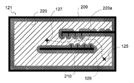
- FIG. 5 is a diagram showing an example of map information
- FIG. 6 is a diagram showing details of the map information.
- the walls 122 and the shelves 123 are obstacles to the traveling of the autonomous mobile device 100, and hereinafter, the walls 122 and the shelves 123 are collectively referred to as obstacles 200.
- FIG. 1 A diagram illustrating an exemplary computing environment in accordance with the present disclosure.
- the map information 121 represents a map as a set of unit blocks 124 in which the travel area of the autonomous mobile device 100 is partitioned into a grid.
- a cost of "100" is given to the unitary domain 124 of the obstacle 200 as information indicating that it is the obstacle 200, and a cost of less than 100 is given to each unitary domain 124 other than that.
- a cost for each unitary domain 124 is given according to the distance from the obstacle 200, for example.
- the route search unit 112 uses the position of the vehicle body center 100 a of the autonomous mobile device 100 as the position of the autonomous mobile device 100 on the area represented by the map information 121 .
- the route searching unit 112 searches for and determines a moving route of the vehicle body center 100 a as the traveling route of the autonomous mobile device 100 .
- FIG. 7 is a graph showing the costs given to the unitary partitions 124 other than the obstacle 200. As shown in FIG.
- the horizontal axis of the graph in FIG. 7 indicates the distance from the unitary domain 124 to the nearest obstacle 200, and the vertical axis indicates the given cost.
- each unitary domain 124 is represented, for example, by a graph line L1 that slopes downward to the right and is convex downward. Also, the graph line L1 becomes a straight line parallel to the horizontal axis where the distance to the obstacle 200 is short. That is, the map information 121 has a cost corresponding to the distance from the obstacle 200 for each location on the map (that is, each unitary division 124), and the unitary division 124 whose distance is shorter than the predetermined distance has the highest cost. Granted.
- the unitary domains 124 assigned the highest cost are distributed around the obstacle 200 as shown in FIG.
- a unit area 124 that is far from the obstacle 200 and given a cost lower than the maximum cost is a drivable area 220 that can be part of the drivable route.
- the length of the linear portion of the graph line L1 parallel to the horizontal axis (that is, the width of the travel prohibited area 210) is set to a length corresponding to the minimum passage width described above.
- the distance to the nearest obstacle 200 is assigned to each unitary domain 124 including the travel prohibited area 210, in addition to the cost. By assigning a distance to each unitary domain 124, it becomes possible to change the cost including the travel prohibited area 210 as well.
- the route search unit 112 described above searches for a travel route within the travelable area 220 and determines a travel route having a short travel length.
- FIG. 8 is a diagram showing an example of a travel route.
- the route search unit 112 sets the starting point 127 to the unitary section 124 where the vehicle body center 100a of the autonomous mobile device 100 is located on the map information 121, and sets the travel route 126 to the given destination 125 (for example, the destination of materials etc.). is searched within the drivable area 220 . Further, the route search unit 112 searches and determines the travel route 126 so that the total cost given to each unitary section 124 on the travel route 126 is small. In other words, the route search unit 112 searches for a route with a smaller total cost as the travel route 126 .
- FIG. 9 is a diagram showing another example of the travel route.
- the travelable area 220 becomes an obstacle 200 and a travel prohibited area 210.
- a travel route 126 passing through the pinched and narrowed bottleneck 220a is determined. Since the travelable area 220 is connected even at the location of the bottleneck 220a, the travel route 126 is searched and determined.
- the travel route 126 passing through the bottleneck 220a is close to the obstacle 200 on both sides of the travel route 126. Therefore, when the autonomous mobile device 100 travels along the travel route 126, the autonomous mobile device 100 may come into contact with the obstacle 200, or the control to avoid the obstacle 200 may become difficult and the vehicle may become unable to travel. . Therefore, in the search for the travel route 126 by the route search unit 112, it is required to exclude the bottleneck 220a.
- the minimum passage width which is the standard for the width of the passage through which the autonomous mobile device 100 is allowed to travel, is set to a width that corresponds to the conditions of the site where the autonomous mobile device 100 is applied.
- the autonomous mobile device 100 may be able to travel without problems even if the safety level is low, and the autonomous mobile device 100 may not be able to travel if the safety level is not high.
- the safety level is changed and the minimum passage width is expanded will be described.
- FIG. 10 is a graph showing expansion of the travel prohibited area 210. As shown in FIG.
- FIG. 10 shows a state in which the graph line L1 shown in FIG. 7 indicated by the dotted line is shifted to the long-distance side (that is, the right side of the drawing) as indicated by the solid line. Due to the shift of the graph line L1, the straight portion corresponding to the travel prohibited area 210 is extended and the width of the travel prohibited area 210 is widened. That is, in the present embodiment, the cost of the travel prohibited area 210 is used as the inhibition information referred to in the present disclosure.
- the route search unit 112 searches for a route based on the map information 121 in which the width of the travel prohibited area 210 is widened.
- FIG. 11 is a diagram showing an example of a travel route 126 based on the map information 121 in which the travel prohibited area 210 is expanded.
- the travel-prohibited area 210 is expanded over the entire area indicated by the map information 121, and the bottleneck 220a is blocked by the travel-prohibited area 210.
- the level setting unit 111 increases the cost sufficiently so that the bottleneck 220a having a narrow width relative to the minimum passage width is blocked by the travel prohibited area 210.
- the route search unit 112 searches and determines a travel route 126 shown in FIG.
- the uniform expansion of the travel-restricted area 210 is an example of means for blocking the narrow narrow road 220a, and the level setting unit 111 blocks the narrow narrow road 220a by a means other than the uniform expansion of the travel-restricted area 210. It's okay.
- the level setting unit 111 may add the travel prohibition area 210 only to the narrow narrow road 220a.
- the level setting unit 111 blocks narrow passages on the map information 121 based on the minimum passage width corresponding to the safety level, and the safety level is selected from a plurality of prepared safety levels on the setting screen. be done. In the present embodiment, three safety levels are prepared as described below.
- FIG. 12 is a diagram conceptually showing the first level.
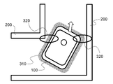
- the first level which is the lowest safety level among the three safety levels, allows the autonomous mobile device 100 to go straight through, but when the autonomous mobile device 100 turns right or left, the stop area 310 is limited to the obstacle 200 .
- This safety level corresponds to the narrow minimum aisle width.
- the autonomous mobile device 100 has a stop area 310 around itself in order to avoid contact with the obstacle 200 during autonomous travel. stops running. Therefore, the width of the stop area 310 should be taken into account when setting the minimum passage width.
- the widths of the autonomous mobile device 100 and the stop area 310 are taken into consideration, and the minimum passage width is defined by the following formula (1).
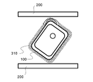
- FIG. 13 is a diagram conceptually showing the second level.
- the second level which is the middle level of the three safety levels, allows the autonomous mobile device 100 to turn right and left, but when the autonomous mobile device 100 makes a 360-degree turn on the spot, the stop area 310 becomes the obstacle 200 .
- the minimum passage width is defined by the following formulas (2) to (4) considering the two points 320 closest to the obstacle 200 when turning left or right.
- Minimum passage width ceil(sqrt(A2+B2+2*A*B*cos( ⁇ /2+atan(A/B)))/resolution)*resolution «(4) however, Resolution: size of unitary division 124 in map information 121 ceil(x): number of unitary divisions 124 corresponding to numerical value x (integer)
- Circumscribed circle radius Radius of a circle that circumscribes the body part 101 of the autonomous mobile device 100
- FIG. 14 is a diagram conceptually showing the third level.
- the third level which is the highest level among the three safety levels, corresponds to the minimum passage width that is wide enough so that the stop area 310 does not interfere with the obstacle 200 even if the autonomous mobile device 100 rotates 360 degrees on the spot. safe level. In other words, at the third level, only routes that do not hinder the freedom of travel in the autonomous mobile device 100 are searched.
- the minimum passage width is defined by the following equation (5) considering the circumscribed circle of the body portion 101 .
- Minimum passage width ceil ((circumscribed circle radius - resolution/2 + stopping distance (maximum) + margin) / resolution) * resolution *2 + resolution ... (5) however, Resolution: size of unitary division 124 in map information 121 ceil(x): number of unitary divisions 124 corresponding to numerical value x (integer) Circumscribed circle radius: Radius of a circle that circumscribes the main body 101 of the autonomous mobile device 100 Stopping distance (maximum): Maximum distance from the main body 101 to the outer edge of the stopping area 310 Margin: From the outer edge of the stopping area 310 to the obstacle 200 It is a grace period provided until
- the vehicle body width is 630 mm
- the radius of the circumscribed circle is 876 mm
- the stopping distance (maximum) is 50 mm
- the margin is 50 mm
- the resolution is 50 mm
- the minimum passage width is 1150 mm.
- the minimum passage width corresponding to each safety level is obtained by considering multiple parameters related to the autonomous mobile device 100.
- the autonomous mobile device 100 may set the first While the degree of freedom of travel is restricted in the same way as the level, the degree of freedom of route search is lower than that of the first level. Therefore, it can be seen that the minimum passage width defined by the above formulas is effective for the autonomous mobile device 100 to travel and search for a route.
- the minimum passage width that is efficient for travel and route search of the autonomous mobile device 100 can be easily set.
- a selector such as a system engineer can easily understand and select a safety level based on the freedom of travel of the autonomous mobile device 100 .
- the safety levels prepared as multiple options are at least the option corresponding to the minimum aisle width that allows straight driving but not turning left or right (i.e. level 1), and the one that corresponds to the minimum aisle width that allows right or left turn. options (ie second level).
- the first level and the second level are easy to select because they clearly correspond to the shape of the passage through which the autonomous mobile device 100 is required to travel.
- the safety level prepared as multiple options, at least the option corresponding to the minimum width of the passage where it is possible to turn right or left and unable to make one turn on the spot (that is, the second level) and 1 on the spot It is also desirable to include an option (ie, a third level) corresponding to the minimum aisle width that can be rotated.
- the second level and the third level are also easy to select because they clearly correspond to the shape of the passage through which the autonomous mobile device is required to travel.
- the safety level is selected and the lower limit of the safety level is set on the setting screen transmitted by the UI unit 150 .
- the safety level is high, the autonomous mobile device 100 has a high degree of freedom in traveling on passages, but the number of passages excluded from the search for travel routes increases, so there may be cases where a travel route that can reach the destination cannot be found. Therefore, in this embodiment, when the travel route cannot be found, a re-search is performed with a lowered safety level.
- the level setting unit 111 lowers the safety level by one, and the inhibition information (cost) corresponding to the minimum passage width corresponding to the safety level one level lower is added to the map information. Append.
- the level setting unit 111 sets the above option (that is, the safety level) to another level having a lower degree of freedom of movement than the above option. It corresponds to an example of an option changing unit that changes to an option.
- the route search unit 112 searches for a travel route that avoids narrow passages based on the minimum passage width corresponding to the other options, based on the map information. This increases the degree of freedom in searching for a travel route, increasing the possibility of finding a travel route that reaches the destination. Equipped with a function to lower the safety level when route search fails, if there is a route with a high safety level, it will be prioritized as a driving route even if the route is long, and only when there is no route with a high safety level It is possible to use a route with a lower safety level to reach the destination.
- the level setting unit 111 selects the option when the route searching unit 112 cannot find a travel route that reaches the destination until reaching a predetermined option among the plurality of options (that is, the safety level). to any other option above.
- a route search is first performed at the third level, and autonomous driving is started if successful. If the route search at the third level fails, the route search is performed at the second level, and autonomous driving is started if successful. If the route search at the second level fails, the route search is performed at the first level, and if successful, autonomous driving is started, but if the route search fails at the first level, the route search is impossible. ends with . Since the lower limit of the safety level can be set, it is possible to prevent the autonomous mobile device 100 from traveling along a low-level route unintended by the user.
- AMR is mentioned as an application example of the autonomous mobile device and the control method of the autonomous mobile device of the present disclosure, but the application of the autonomous mobile device and the control method of the autonomous mobile device of the present disclosure is not limited to the above.
- AGVs Automatic Guided Vehicles
- self-driving cars are examples of the autonomous mobile device and the control method of the autonomous mobile device of the present disclosure.
Landscapes
- Engineering & Computer Science (AREA)
- Radar, Positioning & Navigation (AREA)
- Remote Sensing (AREA)
- Physics & Mathematics (AREA)
- General Physics & Mathematics (AREA)
- Automation & Control Theory (AREA)
- Aviation & Aerospace Engineering (AREA)
- Control Of Position, Course, Altitude, Or Attitude Of Moving Bodies (AREA)
Abstract
One embodiment of an autonomous travel device comprises: a selected unit for selecting one of a plurality of options corresponding to each of a plurality of passage widths having mutually different degrees of freedom of actions permitted in travel along the passage; and a route searching unit for searching, on the basis of map information, for a travel route that avoids passages that are narrow relative to the passage width corresponding to the selected option.
Description
本発明は、自律走行装置および自律走行装置の制御方法に関する。
The present invention relates to an autonomous mobile device and a control method for the autonomous mobile device.
従来、地図情報などに基づいて目的地までの経路を探索して自律的に走行する自律走行装置が知られる。地図情報には障害物の情報などが含まれ、自律走行装置は、自機が走行可能な領域内で走行経路を探索して決定する。走行経路が決定されると自律走行装置は走行経路を辿って自律的に走行する。
Conventionally, there is known an autonomous mobile device that searches for a route to a destination based on map information and travels autonomously. The map information includes information about obstacles and the like, and the autonomous mobile device searches for and determines a travel route within an area in which it can travel. When the travel route is determined, the autonomous mobile device travels autonomously following the travel route.
例えば特許文献1には、ポイントで分割された走行ルートを辿って走行車が走行する走行車システムにおいて、ポイント毎にブロッキング距離を可変にでき、かつブロッキング距離は走行車の機体長により可変である技術の提案が在る。
For example, in Patent Document 1, in a traveling vehicle system in which a traveling vehicle travels along a traveling route divided by points, the blocking distance can be made variable for each point, and the blocking distance can be changed according to the body length of the traveling vehicle. I have a technical proposal.
例えば自律走行装置のその場回転が困難であるような幅のいわゆる隘路では、障害物にぶつかったり、障害物を避ける制御が頻繁に行われて走行不能に陥ったりする虞があるので、経路探索から隘路を除外することが望まれる。
一方で、隘路が一部に存在していても距離が短く、隘路を抜けた先には十分なスペースが存在する場合などは、隘路も含めた経路探索が望まれる。 For example, in a so-called narrow road with a width that makes it difficult for the autonomous mobile device to turn on the spot, there is a risk of colliding with an obstacle or being unable to travel due to frequent control to avoid obstacles. It is desirable to exclude bottlenecks from
On the other hand, when a bottleneck exists in part but the distance is short and there is sufficient space beyond the bottleneck, route search including the bottleneck is desirable.
従って、例えば最小通行幅が自律走行装置の導入される現場の状況に応じて設定されることで、自律走行装置による走行の許される隘路の程度が調整されることが望ましい。
Therefore, it is desirable to adjust the degree of bottleneck that allows the autonomous mobile device to travel, for example, by setting the minimum traffic width according to the situation at the site where the autonomous mobile device is introduced.
しかしながら、最小通路幅は自律走行装置のサイズのみでは求められず、最小通路幅の算出にはセンサの精度や走行制御の精度などの考慮も必要であるため、例えばシステムエンジニアなどの専門家であっても現場の状況に応じた適切な最小通路幅を算出して設定することは難しい。
そこで、本開示は、走行の許される隘路の程度が容易に調整できる自律走行装置を提供することを目的とする。 However, the minimum aisle width cannot be obtained only by the size of the autonomous mobile device, and the calculation of the minimum aisle width requires consideration of the accuracy of the sensor and the accuracy of the travel control. However, it is difficult to calculate and set an appropriate minimum passage width according to site conditions.
Accordingly, an object of the present disclosure is to provide an autonomous mobile device that can easily adjust the degree of a bottleneck on which travel is permitted.
本開示に係る自律走行装置の一態様は、通路の走行において許される動作の自由度が互いに異なる複数の通路幅それぞれに対応した複数の選択肢のうちから1つが選択される被選択部と、選択された上記選択肢に対応した上記通路幅を基準とした狭い通路を避けた走行経路を地図情報に基づいて探索する経路探索部と、を備える。
One aspect of the autonomous mobile device according to the present disclosure is a selected portion that selects one from among a plurality of options corresponding to each of a plurality of passage widths with different degrees of freedom of motion permitted in traveling on the passage; a route search unit that searches for a travel route avoiding narrow passages based on the passage width corresponding to the selected option based on map information.
また、本開示に係る自律走行装置の制御方法の一態様は、通路の走行において許される動作の自由度が互いに異なる複数の通路幅それぞれに対応した複数の選択肢のうちから1つが選択される被選択過程と、選択された上記選択肢に対応した上記通路幅を基準とした狭い通路を避けた走行経路を地図情報に基づいて探索する経路探索過程と、を経る。
Further, one aspect of the method for controlling an autonomous mobile device according to the present disclosure is a subject in which one is selected from among a plurality of options corresponding to each of a plurality of passage widths with different degrees of freedom of motion permitted in passage travel. A selection process and a route search process of searching for a travel route avoiding narrow passages based on the passage width corresponding to the selected option based on map information.
本開示によれば、走行の許される隘路の程度が容易に調整できる。
According to the present disclosure, it is possible to easily adjust the degree of bottleneck that allows travel.
以下、添付の図面を参照しながら、本開示の自律走行装置および自律走行装置の制御方法の実施形態を詳細に説明する。但し、以下の説明が不必要に冗長になるのを避け、当業者の理解を容易にするため、必要以上に詳細な説明は省略する場合がある。例えば、既によく知られた事項の詳細説明や実質的に同一の構成に対する重複説明を省略する場合がある。また、先に説明した図に記載の要素については、後の図の説明において適宜に参照する場合がある。
図1~図3は、本実施形態の自律走行装置の外観を示す図である。図1には側面図が示され、図2には正面図が示され、図3には上面図が示される。 Hereinafter, embodiments of an autonomous mobile device and an autonomous mobile device control method according to the present disclosure will be described in detail with reference to the accompanying drawings. However, in order to avoid unnecessary redundancy in the following description and facilitate the understanding of those skilled in the art, more than necessary detailed description may be omitted. For example, detailed descriptions of well-known matters and redundant descriptions of substantially the same configurations may be omitted. In addition, the elements described in the previously described figures may be appropriately referred to in the description of later figures.
1 to 3 are diagrams showing the appearance of the autonomous mobile device of this embodiment. 1 shows a side view, FIG. 2 shows a front view, and FIG. 3 shows a top view.
本実施形態の自律走行装置100は、例えば工場や公共の場などで資材などを運搬するAMR(Autonomous Mobile Robot)と称される装置である。
自律走行装置100は、本体部101と荷台102とホイール103とキャスタ104と前方センサ105と後方センサ106とを備える。 The autonomousmobile device 100 of the present embodiment is a device called an AMR (Autonomous Mobile Robot) that transports materials and the like in, for example, factories and public places.
The autonomousmobile device 100 includes a main body 101 , a loading platform 102 , wheels 103 , casters 104 , a front sensor 105 and a rear sensor 106 .
自律走行装置100は、本体部101と荷台102とホイール103とキャスタ104と前方センサ105と後方センサ106とを備える。 The autonomous
The autonomous
本体部101は、制御用のコンピュータや駆動の電源などを内蔵する。上下方向から見た本体部101の形状は長方形的な形状である。「長方形的な形状」とは、長方形、長方形の角が面取りされた形状、および長方形の角が丸められた形状を含む。以下、自律走行装置100の前後の目印として前方センサ105の位置が図示される場合がある。
The main unit 101 incorporates a computer for control, a power source for driving, and the like. The main body 101 has a rectangular shape when viewed from above. "Rectangular shape" includes a rectangle, a rectangular shape with chamfered corners, and a rectangular shape with rounded corners. Hereinafter, the position of the front sensor 105 may be illustrated as a mark for the front and rear of the autonomous mobile device 100 .
荷台102には資材などの積載物が積載される。積載物のサイズは荷台102や本体部101のサイズを超える場合があるが、以下では説明の便宜上、特に断らない限り、積載物が荷台102のサイズ内に収まっている場合を例とする。
Loads such as materials are loaded on the carrier 102. Although the size of the load may exceed the size of the loading platform 102 or the main body 101, for convenience of explanation, unless otherwise specified, the case where the load fits within the size of the loading platform 102 will be exemplified below.
ホイール103は、一例として本体部101の左右2箇所に設けられ、本体部101内のモータによって回転駆動される。左右のホイール103は独立に駆動可能であり、自律走行装置100は、左右のホイール103の駆動により、前進、後進、その場回転、および旋回(いわゆるカーブを描く動き)が可能である。
As an example, the wheels 103 are provided on the left and right sides of the main body 101 and are rotated by a motor inside the main body 101 . The left and right wheels 103 can be driven independently, and by driving the left and right wheels 103, the autonomous mobile device 100 can move forward, backward, turn on the spot, and turn (a so-called curve-drawing movement).
キャスタ104は、一例として本体部101の四隅それぞれに設けられ、本体部101が傾かないように支持する。キャスタ104は駆動力を持たず、本体部101の動きに従って転がり、方向も本体部101の動きに従って変わる。
前方センサ105は、本体部101の前方と左右の広い範囲について障害物などを検知する。前方センサ105としては例えば2D-LiDERが用いられる。 As an example, thecasters 104 are provided at each of the four corners of the main body 101 and support the main body 101 so that it does not tilt. The caster 104 does not have a driving force, rolls according to the movement of the main body 101 , and changes its direction according to the movement of the main body 101 .
Thefront sensor 105 detects an obstacle or the like in a wide range in front of the main body 101 and on the left and right. A 2D-LiDER, for example, is used as the front sensor 105 .
前方センサ105は、本体部101の前方と左右の広い範囲について障害物などを検知する。前方センサ105としては例えば2D-LiDERが用いられる。 As an example, the
The
後方センサ106は、本体部101の後方の障害物などを検知する。後方センサ106としては例えば赤外線センサなどが用いられる。後方センサ106は複数のセンサ素子を有してもよく、例えば本体部101の後方外面に沿って設置された複数のセンサ素子による検知が行われる。
図4は、本実施形態の自律走行装置100の機能構成を示す機能ブロック図である。
自律走行装置100は、制御部110と記憶部120と計測部130と駆動部140とユーザインタフェース(UI)部150を備える。
制御部110は、本体部101に内蔵されたコンピュータによって担われる機能であり、自律走行装置100全体を制御する。
記憶部120は、自律走行装置100が走行する領域の地図情報と、その領域上で走行する経路を記憶する。
計測部130は、上記前方センサ105および後方センサ106によって担われる機能であり、障害物などを計測する。 Arear sensor 106 detects an obstacle or the like behind the main body 101 . For example, an infrared sensor or the like is used as the rear sensor 106 . The rear sensor 106 may have a plurality of sensor elements, and detection is performed by, for example, a plurality of sensor elements installed along the rear outer surface of the main body 101 .
FIG. 4 is a functional block diagram showing the functional configuration of the autonomousmobile device 100 of this embodiment.
The autonomousmobile device 100 includes a control unit 110 , a storage unit 120 , a measurement unit 130 , a driving unit 140 and a user interface (UI) unit 150 .
Thecontrol unit 110 is a function performed by a computer built in the main body unit 101 and controls the autonomous mobile device 100 as a whole.
Thestorage unit 120 stores the map information of the area where the autonomous mobile device 100 travels and the route to travel on that area.
Themeasurement unit 130 is a function performed by the front sensor 105 and the rear sensor 106, and measures obstacles and the like.
図4は、本実施形態の自律走行装置100の機能構成を示す機能ブロック図である。
自律走行装置100は、制御部110と記憶部120と計測部130と駆動部140とユーザインタフェース(UI)部150を備える。
制御部110は、本体部101に内蔵されたコンピュータによって担われる機能であり、自律走行装置100全体を制御する。
記憶部120は、自律走行装置100が走行する領域の地図情報と、その領域上で走行する経路を記憶する。
計測部130は、上記前方センサ105および後方センサ106によって担われる機能であり、障害物などを計測する。 A
FIG. 4 is a functional block diagram showing the functional configuration of the autonomous
The autonomous
The
The
The
駆動部140は、本体部101に内蔵された電源やモータと上記ホイール103によって担われる機能である。制御部110による制御に従って駆動部140が駆動することで自律走行装置100が走行する。
The drive unit 140 is a function performed by the power supply and motor built into the main body unit 101 and the wheel 103 . The autonomous mobile device 100 travels by driving the drive unit 140 according to the control by the control unit 110 .
UI部150は、本体部101に内蔵された通信回路などによって担われる機能であり、ブラウザ上で表示される設定画面のデータを送信し、設定画面上で設定された情報を受信する。設定画面では、自律走行装置100が通行可能な最小通路幅を規定したレベルが設定される。レベルとしては、一例として3段階のレベルが用意され、設定画面上でレベルが選択される。また、設定画面上では、選択されたレベルよりも低いレベル(より狭い最小通路幅に対応したレベル)が、レベルの下限として設定される。
レベルの詳細については後述するが、UI部150は、通路の走行において許される動作の自由度が互いに異なる複数の通路幅それぞれに対応した複数の選択肢(例えばレベル)のうちから1つが選択される被選択部の一例に相当する。また、UI部150を介したレベル選択の過程が、本開示に言う被選択過程の一例に相当する。
制御部110は、レベル設定部111と経路探索部112と経路走行部113とを備える。 TheUI unit 150 is a function performed by a communication circuit or the like built in the main unit 101, and transmits data of a setting screen displayed on the browser and receives information set on the setting screen. On the setting screen, a level that defines the minimum passage width through which the autonomous mobile device 100 can pass is set. As an example, three levels are prepared, and the level is selected on the setting screen. Also, on the setting screen, a level lower than the selected level (a level corresponding to a narrower minimum passage width) is set as the lower limit of the level.
The details of the levels will be described later, but theUI unit 150 selects one from a plurality of options (for example, levels) corresponding to each of a plurality of passage widths with different degrees of freedom of motion permitted in passage travel. It corresponds to an example of a selected part. Also, the process of level selection via the UI unit 150 corresponds to an example of the selected process referred to in the present disclosure.
Thecontrol unit 110 includes a level setting unit 111 , a route searching unit 112 and a route running unit 113 .
レベルの詳細については後述するが、UI部150は、通路の走行において許される動作の自由度が互いに異なる複数の通路幅それぞれに対応した複数の選択肢(例えばレベル)のうちから1つが選択される被選択部の一例に相当する。また、UI部150を介したレベル選択の過程が、本開示に言う被選択過程の一例に相当する。
制御部110は、レベル設定部111と経路探索部112と経路走行部113とを備える。 The
The details of the levels will be described later, but the
The
レベル設定部111は、UI部150を介して受信されたレベルの情報に基づいて、レベルに対応した最小通路幅を基準とした狭い通路を塞ぐ処理を、記憶部120に記憶された地図情報に対して施す。ここで、最小通路幅を基準とした狭い通路とは、最小通路幅以下の幅を有する通路であってもよいし、最小通路幅未満の幅を有する通路であってもよい。また、狭い箇所が所定長以上続く場合にのみ狭い通路として塞いでもよいし、狭い箇所の長さに関わらず狭い通路として塞いでもよい。レベル設定部111は、本開示に言う情報付加部の一例に相当し、最小通路幅を基準とした上記狭い通路における走行を阻害する阻害情報を地図情報に付加する。阻害情報の具体例については後述する。
Based on the level information received via the UI unit 150, the level setting unit 111 stores the map information stored in the storage unit 120 in the map information stored in the storage unit 120 for closing narrow passages based on the minimum width corresponding to the level. apply to Here, the narrow passage based on the minimum passage width may be a passage having a width equal to or less than the minimum passage width, or may be a passage having a width less than the minimum passage width. Further, the narrow passage may be blocked only when the narrow portion continues for a predetermined length or more, or the narrow passage may be closed regardless of the length of the narrow portion. The level setting unit 111 corresponds to an example of the information addition unit referred to in the present disclosure, and adds obstruction information that obstructs traveling in the narrow passage based on the minimum passage width to the map information. A specific example of the inhibition information will be described later.
経路探索部112は、記憶部120に記憶された地図情報に基づいて目的地までの経路を探索して決定し、決定した経路を記憶部120に記憶させる。本実施形態では、経路探索部112は経路として、地図情報に示された障害物などを避けながら目的地に到達可能な経路を探索し、最短で目的地に到達する経路を決定する。また、本実施形態では、経路探索部112は、上記阻害情報が付加された地図情報に基づいて走行経路を探索する。つまり、経路探索部112は、本開示に言う経路探索部の一例に相当し、選択された選択肢(例えばレベル)に対応した最小通路幅を基準とした狭い通路を避けた走行経路を地図情報に基づいて探索する。また、経路探索部112における経路探索の過程が、本開示に言う経路探索過程の一例に相当する。レベル設定部111によって阻害情報が付加された地図情報で経路探索部112が経路を探索する構成により、経路探索部112における経路探索のアルゴリズムとして、基準の最小通路幅に依存しない共通のアルゴリズムが採用可能となる。
The route search unit 112 searches for and determines a route to the destination based on the map information stored in the storage unit 120, and stores the determined route in the storage unit 120. In this embodiment, the route searching unit 112 searches for a route that can reach the destination while avoiding obstacles and the like shown in the map information, and determines the shortest route to reach the destination. Further, in this embodiment, the route searching unit 112 searches for a travel route based on the map information to which the inhibition information is added. That is, the route search unit 112 corresponds to an example of the route search unit referred to in the present disclosure, and maps a travel route that avoids narrow passages based on the minimum passage width corresponding to the selected option (for example, level) to the map information. Explore based on. Further, the route search process in the route search unit 112 corresponds to an example of the route search process referred to in the present disclosure. A common algorithm that does not depend on the standard minimum passage width is adopted as a route search algorithm in the route search unit 112 by a configuration in which the route search unit 112 searches for a route based on the map information to which the obstruction information is added by the level setting unit 111. It becomes possible.
経路走行部113は、記憶部120に記憶された経路を辿って自律走行装置100が走行するように駆動部140を制御する。本実施形態では、経路走行部113は、計測部130によって計測された障害物を避けるための制御も行う。
図5は、地図情報の一例を示す図であり、図6は、地図情報の詳細を示す図である。 Theroute running unit 113 controls the driving unit 140 so that the autonomous mobile device 100 runs along the route stored in the storage unit 120 . In this embodiment, the route running unit 113 also performs control for avoiding obstacles measured by the measuring unit 130 .
FIG. 5 is a diagram showing an example of map information, and FIG. 6 is a diagram showing details of the map information.
図5は、地図情報の一例を示す図であり、図6は、地図情報の詳細を示す図である。 The
FIG. 5 is a diagram showing an example of map information, and FIG. 6 is a diagram showing details of the map information.
地図情報121には、壁122や棚123の情報が示される。壁122や棚123は自律走行装置100の走行にとって障害となる物体であり、以下では壁122や棚123を含めて障害物200と総称する。
Information on walls 122 and shelves 123 is shown in map information 121 . The walls 122 and the shelves 123 are obstacles to the traveling of the autonomous mobile device 100, and hereinafter, the walls 122 and the shelves 123 are collectively referred to as obstacles 200. FIG.
図6に示すように、地図情報121は、自律走行装置100の走行領域が格子状に区切られた単位区画124の集合として地図を表す。障害物200の単位区画124には障害物200であることを示す情報として例えばコスト「100」が付与され、それ以外の各単位区画124には100未満のコストが付与される。各単位区画124に対するコストとしては、例えば、障害物200からの距離に応じて付与される。
As shown in FIG. 6, the map information 121 represents a map as a set of unit blocks 124 in which the travel area of the autonomous mobile device 100 is partitioned into a grid. For example, a cost of "100" is given to the unitary domain 124 of the obstacle 200 as information indicating that it is the obstacle 200, and a cost of less than 100 is given to each unitary domain 124 other than that. A cost for each unitary domain 124 is given according to the distance from the obstacle 200, for example.
経路探索部112は、地図情報121が表す領域上での自律走行装置100の位置として、自律走行装置100の車体中心100aの位置を用いる。経路探索部112は、自律走行装置100の走行経路として車体中心100aの移動経路を探索して決定する。
図7は、障害物200以外の単位区画124に対して付与されるコストを表すグラフである。
図7のグラフの横軸は、単位区画124から最近傍の障害物200までの距離を示し、縦軸は付与されるコストを示す。 Theroute search unit 112 uses the position of the vehicle body center 100 a of the autonomous mobile device 100 as the position of the autonomous mobile device 100 on the area represented by the map information 121 . The route searching unit 112 searches for and determines a moving route of the vehicle body center 100 a as the traveling route of the autonomous mobile device 100 .
FIG. 7 is a graph showing the costs given to theunitary partitions 124 other than the obstacle 200. As shown in FIG.
The horizontal axis of the graph in FIG. 7 indicates the distance from theunitary domain 124 to the nearest obstacle 200, and the vertical axis indicates the given cost.
図7は、障害物200以外の単位区画124に対して付与されるコストを表すグラフである。
図7のグラフの横軸は、単位区画124から最近傍の障害物200までの距離を示し、縦軸は付与されるコストを示す。 The
FIG. 7 is a graph showing the costs given to the
The horizontal axis of the graph in FIG. 7 indicates the distance from the
各単位区画124に付与されるコストは、例えば右下がりで下に凸のグラフラインL1で表される。また、グラフラインL1は、障害物200までの距離が短い所では横軸と平行の直線になる。つまり、地図情報121は、地図上の各箇所(つまり各単位区画124)について、障害物200からの距離に応じたコストを有し、距離が所定距離よりも短い単位区画124については最高コストが付与される。最高コストが付与された単位区画124は図6に示すように障害物200の周辺に分布することになり、コストが高すぎることで経路探索から除外される走行禁止領域210となる。障害物200までの距離が遠くて最高コストよりも低いコストが付与された単位区画124は、走行経路の一部となり得る走行可能領域220である。
The cost given to each unitary domain 124 is represented, for example, by a graph line L1 that slopes downward to the right and is convex downward. Also, the graph line L1 becomes a straight line parallel to the horizontal axis where the distance to the obstacle 200 is short. That is, the map information 121 has a cost corresponding to the distance from the obstacle 200 for each location on the map (that is, each unitary division 124), and the unitary division 124 whose distance is shorter than the predetermined distance has the highest cost. Granted. The unitary domains 124 assigned the highest cost are distributed around the obstacle 200 as shown in FIG. A unit area 124 that is far from the obstacle 200 and given a cost lower than the maximum cost is a drivable area 220 that can be part of the drivable route.
本実施形態では、一例として、グラフラインL1における横軸と平行な直線部分の長さ(即ち走行禁止領域210の幅)が、上述した最小通路幅に対応した長さに設定される。
In the present embodiment, as an example, the length of the linear portion of the graph line L1 parallel to the horizontal axis (that is, the width of the travel prohibited area 210) is set to a length corresponding to the minimum passage width described above.
本実施形態では、走行禁止領域210も含めた各単位区画124に対し、コストとは別に、最近傍の障害物200までの距離が付与される。各単位区画124に対し距離が付与されることで、走行禁止領域210も含めたコストの変更が可能となる。
上述した経路探索部112は、走行可能領域220内で走行経路を探索し、走行長が短い走行経路を決定する。
図8は、走行経路の一例を示す図である。 In this embodiment, the distance to thenearest obstacle 200 is assigned to each unitary domain 124 including the travel prohibited area 210, in addition to the cost. By assigning a distance to each unitary domain 124, it becomes possible to change the cost including the travel prohibited area 210 as well.
Theroute search unit 112 described above searches for a travel route within the travelable area 220 and determines a travel route having a short travel length.
FIG. 8 is a diagram showing an example of a travel route.
上述した経路探索部112は、走行可能領域220内で走行経路を探索し、走行長が短い走行経路を決定する。
図8は、走行経路の一例を示す図である。 In this embodiment, the distance to the
The
FIG. 8 is a diagram showing an example of a travel route.
経路探索部112は、地図情報121上で自律走行装置100の車体中心100aが位置する単位区画124を出発点127とし、与えられた目的地125(例えば資材などの運搬先)までの走行経路126を走行可能領域220内で探索する。また、経路探索部112は、走行経路126上の各単位区画124に付与されたコストの総計が小さくなるように走行経路126を探索して決定する。言い換えると経路探索部112は、走行経路126として、コストの合計が小さくなる経路を探索する。
The route search unit 112 sets the starting point 127 to the unitary section 124 where the vehicle body center 100a of the autonomous mobile device 100 is located on the map information 121, and sets the travel route 126 to the given destination 125 (for example, the destination of materials etc.). is searched within the drivable area 220 . Further, the route search unit 112 searches and determines the travel route 126 so that the total cost given to each unitary section 124 on the travel route 126 is small. In other words, the route search unit 112 searches for a route with a smaller total cost as the travel route 126 .
この結果、走行距離が短い走行経路126が探索されて決定される。また、障害物200の周辺に走行禁止領域210が設けられることにより、走行経路126は走行禁止領域210を避けて通り、自律走行装置100は車体中心100aを障害物200から所定距離以上保って走行する。これにより、自律走行装置100と障害物200との接触が回避される。
図9は、走行経路の他の例を示す図である。 As a result, atravel route 126 with a short travel distance is searched and determined. In addition, since the travel prohibited area 210 is provided around the obstacle 200, the travel route 126 avoids the travel prohibited area 210, and the autonomous mobile device 100 travels while keeping the vehicle body center 100a from the obstacle 200 by a predetermined distance or more. do. This avoids contact between the autonomous mobile device 100 and the obstacle 200 .
FIG. 9 is a diagram showing another example of the travel route.
図9は、走行経路の他の例を示す図である。 As a result, a
FIG. 9 is a diagram showing another example of the travel route.
図9に示す例では、地図情報121が表す領域上で出発点127から目的地125まで走行距離の短い走行経路126が探索された結果、走行可能領域220が障害物200および走行禁止領域210に挟まれて細くなった隘路220aを通る走行経路126が決定される。隘路220aの箇所でも走行可能領域220が繋がっているため走行経路126が探索されて決定される。
In the example shown in FIG. 9, as a result of searching for a short travel route 126 from a starting point 127 to a destination 125 on the area represented by the map information 121, the travelable area 220 becomes an obstacle 200 and a travel prohibited area 210. A travel route 126 passing through the pinched and narrowed bottleneck 220a is determined. Since the travelable area 220 is connected even at the location of the bottleneck 220a, the travel route 126 is searched and determined.
自律走行装置100の走行動作の自由度が大きく制限される程度に隘路220aの幅が狭い場合には、隘路220aを通る走行経路126では、走行経路126を挟んだ両側が障害物200に近い。このため、走行経路126を辿って自律走行装置100が走行する場合に、自律走行装置100が障害物200に接触したり、障害物200を避ける制御が困難で走行不能となったりする虞がある。このため、経路探索部112による走行経路126の探索において、隘路220aを除外することが求められる。
When the width of the bottleneck 220a is so narrow that the degree of freedom of the autonomous mobile device 100's traveling motion is greatly restricted, the travel route 126 passing through the bottleneck 220a is close to the obstacle 200 on both sides of the travel route 126. Therefore, when the autonomous mobile device 100 travels along the travel route 126, the autonomous mobile device 100 may come into contact with the obstacle 200, or the control to avoid the obstacle 200 may become difficult and the vehicle may become unable to travel. . Therefore, in the search for the travel route 126 by the route search unit 112, it is required to exclude the bottleneck 220a.
一方で、幅の狭い隘路220aであっても、周辺の状況などによっては、自律走行装置100が例えば直進走行して通り抜けることができる場合がある。従って、自律走行装置100の走行が許される通路幅の基準である最小通路幅は、自律走行装置100が適用される現場の状況に応じた幅に設定される。
On the other hand, even if the narrow road 220a is narrow, the autonomous mobile device 100 may be able to drive straight through it, depending on the surrounding conditions. Therefore, the minimum passage width, which is the standard for the width of the passage through which the autonomous mobile device 100 is allowed to travel, is set to a width that corresponds to the conditions of the site where the autonomous mobile device 100 is applied.
最小通路幅が大きいほど自律走行装置100は安全に走行可能であるため、最小通路幅を規定する上記レベルは、自律走行装置100の安全レベルと言い換えてもよい。つまり、自律走行装置100が適用される現場の状況によって、低い安全レベルであっても自律走行装置100が問題なく走行可能である場合もあるし、高い安全レベルでないと自律走行装置100が走行不可能である場合もある。
ここで、安全レベルが変更されて最小通路幅が拡大された場合について説明する。 The larger the minimum passage width, the safer the autonomousmobile device 100 can travel. In other words, depending on the situation of the site where the autonomous mobile device 100 is applied, the autonomous mobile device 100 may be able to travel without problems even if the safety level is low, and the autonomous mobile device 100 may not be able to travel if the safety level is not high. Sometimes it is possible.
Here, a case where the safety level is changed and the minimum passage width is expanded will be described.
ここで、安全レベルが変更されて最小通路幅が拡大された場合について説明する。 The larger the minimum passage width, the safer the autonomous
Here, a case where the safety level is changed and the minimum passage width is expanded will be described.
上述したように、図7に示すグラフラインL1における横軸と平行な直線部分の長さ(即ち走行禁止領域210の幅)は、最小通路幅に応じた長さに設定されるので、最小通路幅が拡大された場合には、走行禁止領域210の幅も拡大される。
図10は、走行禁止領域210の拡張を示すグラフである。 As described above, the length of the straight line portion parallel to the horizontal axis in the graph line L1 shown in FIG. When the width is increased, the width of the travel prohibitedarea 210 is also increased.
FIG. 10 is a graph showing expansion of the travel prohibitedarea 210. As shown in FIG.
図10は、走行禁止領域210の拡張を示すグラフである。 As described above, the length of the straight line portion parallel to the horizontal axis in the graph line L1 shown in FIG. When the width is increased, the width of the travel prohibited
FIG. 10 is a graph showing expansion of the travel prohibited
図10には、点線で示された図7に示すグラフラインL1が、実線で示されるように長距離側(即ち図の右側)にシフトされた状態が示される。グラフラインL1のシフトにより、走行禁止領域210に相当する直線箇所が延びて走行禁止領域210の幅が広がる。つまり、本実施形態では、本開示に言う阻害情報として走行禁止領域210のコストが用いられる。
経路探索部112は、走行禁止領域210の幅が広がった地図情報121に基づいて経路探索を行う。
図11は、走行禁止領域210が拡張された地図情報121に基づいた走行経路126の例を示す図である。 FIG. 10 shows a state in which the graph line L1 shown in FIG. 7 indicated by the dotted line is shifted to the long-distance side (that is, the right side of the drawing) as indicated by the solid line. Due to the shift of the graph line L1, the straight portion corresponding to the travel prohibitedarea 210 is extended and the width of the travel prohibited area 210 is widened. That is, in the present embodiment, the cost of the travel prohibited area 210 is used as the inhibition information referred to in the present disclosure.
Theroute search unit 112 searches for a route based on the map information 121 in which the width of the travel prohibited area 210 is widened.
FIG. 11 is a diagram showing an example of atravel route 126 based on the map information 121 in which the travel prohibited area 210 is expanded.
経路探索部112は、走行禁止領域210の幅が広がった地図情報121に基づいて経路探索を行う。
図11は、走行禁止領域210が拡張された地図情報121に基づいた走行経路126の例を示す図である。 FIG. 10 shows a state in which the graph line L1 shown in FIG. 7 indicated by the dotted line is shifted to the long-distance side (that is, the right side of the drawing) as indicated by the solid line. Due to the shift of the graph line L1, the straight portion corresponding to the travel prohibited
The
FIG. 11 is a diagram showing an example of a
コストが増えたことにより、地図情報121が示す領域全体で走行禁止領域210が拡張されて隘路220aが走行禁止領域210によって塞がれる。逆に言えば、レベル設定部111は、最小通路幅を基準とした狭い幅を有する隘路220aが走行禁止領域210によって塞がれるように、十分にコストを増やす。この結果、経路探索部112は、出発点127から目的地125まで隘路220aを避けて到達する図11の走行経路126を探索して決定する。
Due to the increase in cost, the travel-prohibited area 210 is expanded over the entire area indicated by the map information 121, and the bottleneck 220a is blocked by the travel-prohibited area 210. Conversely, the level setting unit 111 increases the cost sufficiently so that the bottleneck 220a having a narrow width relative to the minimum passage width is blocked by the travel prohibited area 210. FIG. As a result, the route search unit 112 searches and determines a travel route 126 shown in FIG.
なお、走行禁止領域210の一律の拡張は、狭い幅の隘路220aを塞ぐ手段の一例であり、レベル設定部111は、走行禁止領域210の一律の拡張以外の手段で狭い幅の隘路220aを塞いでもよい。例えばレベル設定部111は、狭い幅の隘路220a部分にだけ走行禁止領域210を追加してもよい。
The uniform expansion of the travel-restricted area 210 is an example of means for blocking the narrow narrow road 220a, and the level setting unit 111 blocks the narrow narrow road 220a by a means other than the uniform expansion of the travel-restricted area 210. It's okay. For example, the level setting unit 111 may add the travel prohibition area 210 only to the narrow narrow road 220a.
上述したように、レベル設定部111は、安全レベルに対応した最小通路幅を基準とした狭い通路を地図情報121上で塞ぎ、安全レベルは、用意された複数の安全レベルから設定画面上で選択される。本実施形態では、以下説明する3段階の安全レベルが用意される。
図12は、第1レベルを概念的に示す図である。 As described above, thelevel setting unit 111 blocks narrow passages on the map information 121 based on the minimum passage width corresponding to the safety level, and the safety level is selected from a plurality of prepared safety levels on the setting screen. be done. In the present embodiment, three safety levels are prepared as described below.
FIG. 12 is a diagram conceptually showing the first level.
図12は、第1レベルを概念的に示す図である。 As described above, the
FIG. 12 is a diagram conceptually showing the first level.
3段階の安全レベルのうち最も低レベルの第1レベルは、自律走行装置100が直進して通り抜けることができるが、自律走行装置100が右折あるいは左折すると停止領域310が障害物200に掛かる程度に狭い最小通路幅に対応した安全レベルである。
The first level, which is the lowest safety level among the three safety levels, allows the autonomous mobile device 100 to go straight through, but when the autonomous mobile device 100 turns right or left, the stop area 310 is limited to the obstacle 200 . This safety level corresponds to the narrow minimum aisle width.
自律走行装置100は、自律走行に際して障害物200との接触を避けるため、自機の周辺に停止領域310を有し、停止領域310中で障害物200が検知された場合には自律走行装置100が走行を停止する。従って、最小通路幅の設定には、停止領域310の広さなどが考慮された設定が必要である。
第1レベルでは、自律走行装置100および停止領域310の横幅が考慮されて最小通路幅が下記式(1)で定義される。
最小通路幅=ceil((車体幅/2-分解能/2+停止距離(横)+マージン)/分解能)*分解能*2+分解能 …… (1)
但し、
分解能:地図情報121における単位区画124のサイズ
ceil(x):数値xに相当する単位区画124の数(整数)
停止距離(横):自律走行装置100の横幅方向における本体部101から停止領域310の外縁までの距離
マージン:停止領域310の外縁から障害物200までの間に設けられた猶予
である。
一例として、車体幅が630mm、停止距離(横)が50mm、マージンが50mm、分解能が50mmであるとすると最小通路幅は850mmとなる。
図13は、第2レベルを概念的に示す図である。 The autonomousmobile device 100 has a stop area 310 around itself in order to avoid contact with the obstacle 200 during autonomous travel. stops running. Therefore, the width of the stop area 310 should be taken into account when setting the minimum passage width.
At the first level, the widths of the autonomousmobile device 100 and the stop area 310 are taken into consideration, and the minimum passage width is defined by the following formula (1).
Minimum passage width = ceil ((body width/2 - resolution/2 + stopping distance (lateral) + margin)/resolution) * resolution *2 + resolution …… (1)
however,
Resolution: size ofunitary division 124 in map information 121 ceil(x): number of unitary divisions 124 corresponding to numerical value x (integer)
Stopping distance (horizontal): Distance from themain body 101 to the outer edge of the stopping area 310 in the width direction of the autonomous mobile device 100 Margin: A margin provided between the outer edge of the stopping area 310 and the obstacle 200 .
As an example, if the vehicle body width is 630 mm, the stopping distance (lateral) is 50 mm, the margin is 50 mm, and the resolution is 50 mm, the minimum passage width is 850 mm.
FIG. 13 is a diagram conceptually showing the second level.
第1レベルでは、自律走行装置100および停止領域310の横幅が考慮されて最小通路幅が下記式(1)で定義される。
最小通路幅=ceil((車体幅/2-分解能/2+停止距離(横)+マージン)/分解能)*分解能*2+分解能 …… (1)
但し、
分解能:地図情報121における単位区画124のサイズ
ceil(x):数値xに相当する単位区画124の数(整数)
停止距離(横):自律走行装置100の横幅方向における本体部101から停止領域310の外縁までの距離
マージン:停止領域310の外縁から障害物200までの間に設けられた猶予
である。
一例として、車体幅が630mm、停止距離(横)が50mm、マージンが50mm、分解能が50mmであるとすると最小通路幅は850mmとなる。
図13は、第2レベルを概念的に示す図である。 The autonomous
At the first level, the widths of the autonomous
Minimum passage width = ceil ((body width/2 - resolution/2 + stopping distance (lateral) + margin)/resolution) * resolution *2 + resolution …… (1)
however,
Resolution: size of
Stopping distance (horizontal): Distance from the
As an example, if the vehicle body width is 630 mm, the stopping distance (lateral) is 50 mm, the margin is 50 mm, and the resolution is 50 mm, the minimum passage width is 850 mm.
FIG. 13 is a diagram conceptually showing the second level.
3段階の安全レベルのうち中間レベルの第2レベルは、自律走行装置100が右折および左折することができるが、自律走行装置100が360度のその場回転を行うと停止領域310が障害物200に掛かる程度に狭い最小通路幅に対応した安全レベルである。
第2レベルでは、右左折時に障害物200と最接近する2つの箇所320が考慮されて最小通路幅が下記式(2)~式(4)で定義される。
A=ceil((横幅/2-分解能/2+停止距離(横)+マージン)/分解能)*分解能+分解能/2 ……(2)
B=ceil((外接円半径-分解能/2+停止距離(最大)+マージン)/分解能)*分解能 +分解能/2 ……(3)
最小通路幅=ceil(sqrt(A2+B2+2*A*B*cos(π/2+atan(A/B)))/分解能)*分解能 ……(4)
但し、
分解能:地図情報121における単位区画124のサイズ
ceil(x):数値xに相当する単位区画124の数(整数)
外接円半径:自律走行装置100の本体部101に外接する円の半径
停止距離(横):自律走行装置100の横幅方向における本体部101から停止領域310の外縁までの距離
停止距離(最大):本体部101から停止領域310の外縁までの距離の最大値
マージン:停止領域310の外縁から障害物200までの間に設けられた猶予
である。 The second level, which is the middle level of the three safety levels, allows the autonomousmobile device 100 to turn right and left, but when the autonomous mobile device 100 makes a 360-degree turn on the spot, the stop area 310 becomes the obstacle 200 . It is a safety level corresponding to the minimum width of the passage that is narrow enough to cover
At the second level, the minimum passage width is defined by the following formulas (2) to (4) considering the twopoints 320 closest to the obstacle 200 when turning left or right.
A = ceil((width/2-resolution/2+stopping distance (horizontal)+margin)/resolution)*resolution+resolution/2 ……(2)
B = ceil ((circumscribed circle radius - resolution/2 + stopping distance (maximum) + margin)/resolution) * resolution + resolution/2 ……(3)
Minimum passage width = ceil(sqrt(A2+B2+2*A*B*cos(π/2+atan(A/B)))/resolution)*resolution ……(4)
however,
Resolution: size ofunitary division 124 in map information 121 ceil(x): number of unitary divisions 124 corresponding to numerical value x (integer)
Circumscribed circle radius: Radius of a circle that circumscribes thebody part 101 of the autonomous mobile device 100 Stopping distance (horizontal): Distance from the body part 101 to the outer edge of the stop area 310 in the horizontal direction of the autonomous mobile device 100 Stopping distance (maximum): Maximum value of the distance from the main body 101 to the outer edge of the stop area 310 Margin: A margin provided between the outer edge of the stop area 310 and the obstacle 200 .
第2レベルでは、右左折時に障害物200と最接近する2つの箇所320が考慮されて最小通路幅が下記式(2)~式(4)で定義される。
A=ceil((横幅/2-分解能/2+停止距離(横)+マージン)/分解能)*分解能+分解能/2 ……(2)
B=ceil((外接円半径-分解能/2+停止距離(最大)+マージン)/分解能)*分解能 +分解能/2 ……(3)
最小通路幅=ceil(sqrt(A2+B2+2*A*B*cos(π/2+atan(A/B)))/分解能)*分解能 ……(4)
但し、
分解能:地図情報121における単位区画124のサイズ
ceil(x):数値xに相当する単位区画124の数(整数)
外接円半径:自律走行装置100の本体部101に外接する円の半径
停止距離(横):自律走行装置100の横幅方向における本体部101から停止領域310の外縁までの距離
停止距離(最大):本体部101から停止領域310の外縁までの距離の最大値
マージン:停止領域310の外縁から障害物200までの間に設けられた猶予
である。 The second level, which is the middle level of the three safety levels, allows the autonomous
At the second level, the minimum passage width is defined by the following formulas (2) to (4) considering the two
A = ceil((width/2-resolution/2+stopping distance (horizontal)+margin)/resolution)*resolution+resolution/2 ……(2)
B = ceil ((circumscribed circle radius - resolution/2 + stopping distance (maximum) + margin)/resolution) * resolution + resolution/2 ……(3)
Minimum passage width = ceil(sqrt(A2+B2+2*A*B*cos(π/2+atan(A/B)))/resolution)*resolution ……(4)
however,
Resolution: size of
Circumscribed circle radius: Radius of a circle that circumscribes the
一例として、車体幅が630mm、外接円の半径が876mm、停止距離(全方向)が50mm、マージンが50mm、分解能が50mmであるとすると最小通路幅は1050mmとなる。
図14は、第3レベルを概念的に示す図である。 As an example, if the vehicle body width is 630 mm, the radius of the circumscribed circle is 876 mm, the stopping distance (all directions) is 50 mm, the margin is 50 mm, and the resolution is 50 mm, then the minimum width of the passage is 1050 mm.
FIG. 14 is a diagram conceptually showing the third level.
3段階の安全レベルのうち最も高レベルの第3レベルは、自律走行装置100が360度のその場回転を行っても停止領域310が障害物200に掛からない程度に広い最小通路幅に対応した安全レベルである。つまり、第3レベルでは、自律走行装置100における走行の自由度が妨げられない経路のみが探索対象となる。
第3レベルでは、本体部101に対する外接円が考慮されて最小通路幅が下記式(5)で定義される。
最小通路幅=ceil((外接円半径-分解能/2+停止距離(最大)+マージン)/分解能)*分解能*2+分解能
……(5)
但し、
分解能:地図情報121における単位区画124のサイズ
ceil(x):数値xに相当する単位区画124の数(整数)
外接円半径:自律走行装置100の本体部101に外接する円の半径
停止距離(最大):本体部101から停止領域310の外縁までの距離の最大値
マージン:停止領域310の外縁から障害物200までの間に設けられた猶予
である。 The third level, which is the highest level among the three safety levels, corresponds to the minimum passage width that is wide enough so that thestop area 310 does not interfere with the obstacle 200 even if the autonomous mobile device 100 rotates 360 degrees on the spot. safe level. In other words, at the third level, only routes that do not hinder the freedom of travel in the autonomous mobile device 100 are searched.
At the third level, the minimum passage width is defined by the following equation (5) considering the circumscribed circle of thebody portion 101 .
Minimum passage width = ceil ((circumscribed circle radius - resolution/2 + stopping distance (maximum) + margin) / resolution) * resolution *2 + resolution … (5)
however,
Resolution: size ofunitary division 124 in map information 121 ceil(x): number of unitary divisions 124 corresponding to numerical value x (integer)
Circumscribed circle radius: Radius of a circle that circumscribes themain body 101 of the autonomous mobile device 100 Stopping distance (maximum): Maximum distance from the main body 101 to the outer edge of the stopping area 310 Margin: From the outer edge of the stopping area 310 to the obstacle 200 It is a grace period provided until
第3レベルでは、本体部101に対する外接円が考慮されて最小通路幅が下記式(5)で定義される。
最小通路幅=ceil((外接円半径-分解能/2+停止距離(最大)+マージン)/分解能)*分解能*2+分解能
……(5)
但し、
分解能:地図情報121における単位区画124のサイズ
ceil(x):数値xに相当する単位区画124の数(整数)
外接円半径:自律走行装置100の本体部101に外接する円の半径
停止距離(最大):本体部101から停止領域310の外縁までの距離の最大値
マージン:停止領域310の外縁から障害物200までの間に設けられた猶予
である。 The third level, which is the highest level among the three safety levels, corresponds to the minimum passage width that is wide enough so that the
At the third level, the minimum passage width is defined by the following equation (5) considering the circumscribed circle of the
Minimum passage width = ceil ((circumscribed circle radius - resolution/2 + stopping distance (maximum) + margin) / resolution) * resolution *2 + resolution … (5)
however,
Resolution: size of
Circumscribed circle radius: Radius of a circle that circumscribes the
一例として、車体幅が630mm、外接円の半径が876mm、停止距離(最大)が50mm、マージンが50mm、分解能が50mmであるとすると最小通路幅は1150mmとなる。
As an example, if the vehicle body width is 630 mm, the radius of the circumscribed circle is 876 mm, the stopping distance (maximum) is 50 mm, the margin is 50 mm, and the resolution is 50 mm, the minimum passage width is 1150 mm.
このように、各安全レベルに対応した最小通路幅は、自律走行装置100に関わる複数のパラメータが考慮されて求められる。ここで仮に、最小通路幅として、第1レベルに対応した最小通路幅と、第2レベルに対応した最小通路幅との間の値が設定された場合には、自律走行装置100は、第1レベルと同様に走行の自由度が制限される一方で、経路探索の自由度は第1レベルよりも下がる。従って、最小通路幅としては、上述した各式で定義される最小通路幅が自律走行装置100の走行および経路探索にとって効率的であることがわかる。
In this way, the minimum passage width corresponding to each safety level is obtained by considering multiple parameters related to the autonomous mobile device 100. Here, if a value between the minimum passage width corresponding to the first level and the minimum passage width corresponding to the second level is set as the minimum passage width, the autonomous mobile device 100 may set the first While the degree of freedom of travel is restricted in the same way as the level, the degree of freedom of route search is lower than that of the first level. Therefore, it can be seen that the minimum passage width defined by the above formulas is effective for the autonomous mobile device 100 to travel and search for a route.
つまり、自律走行装置100における通路走行の自由度に対応した複数の安全レベルが用意されて選択されることにより、自律走行装置100の走行および経路探索にとって効率的な最小通路幅が容易に設定されることになる。また、安全レベルの選択に際しては、自律走行装置100の走行の自由度に基づいてシステムエンジニアなどの選択者が安全レベルを容易に理解して選択することができる。
That is, by preparing and selecting a plurality of safety levels corresponding to the degree of freedom of passage travel in the autonomous mobile device 100, the minimum passage width that is efficient for travel and route search of the autonomous mobile device 100 can be easily set. will be Further, when selecting a safety level, a selector such as a system engineer can easily understand and select a safety level based on the freedom of travel of the autonomous mobile device 100 .
複数の選択肢として用意される安全レベルとしては、少なくとも、直進走行が可能で右左折が不能な最小通路幅に対応した選択肢(即ち第1レベル)と、右左折が可能な最小通路幅に対応した選択肢(即ち第2レベル)とを含むことが望ましい。上記第1レベルと上記第2レベルは、自律走行装置100に走行が求められる通路形状との対応が明瞭であるため選択が容易である。
The safety levels prepared as multiple options are at least the option corresponding to the minimum aisle width that allows straight driving but not turning left or right (i.e. level 1), and the one that corresponds to the minimum aisle width that allows right or left turn. options (ie second level). The first level and the second level are easy to select because they clearly correspond to the shape of the passage through which the autonomous mobile device 100 is required to travel.
また、複数の選択肢として用意される安全レベルとしては、少なくとも、右左折が可能でその場での1回転が不能な最小通路幅に対応した選択肢(即ち第2レベル)と、その場での1回転が可能な最小通路幅に対応した選択肢(即ち第3レベル)とを含むことも望ましい。上記第2レベルと上記第3レベルも、自律走行装置に走行が求められる通路形状との対応が明瞭であるため選択が容易である。
In addition, as the safety level prepared as multiple options, at least the option corresponding to the minimum width of the passage where it is possible to turn right or left and unable to make one turn on the spot (that is, the second level) and 1 on the spot It is also desirable to include an option (ie, a third level) corresponding to the minimum aisle width that can be rotated. The second level and the third level are also easy to select because they clearly correspond to the shape of the passage through which the autonomous mobile device is required to travel.
上述したように、本実施形態では、UI部150が送信する設定画面上で、安全レベルの選択と共に安全レベルの下限設定が行われる。安全レベルが高い場合、自律走行装置100における通路走行の自由度が高い一方で、走行経路の探索から除外される通路も増えるので、目的地に到達可能な走行経路が見つからない場合が考えられる。そのため、本実施形態では、走行経路が見つからない場合に安全レベルを下げた再探索が行われる。
As described above, in the present embodiment, the safety level is selected and the lower limit of the safety level is set on the setting screen transmitted by the UI unit 150 . When the safety level is high, the autonomous mobile device 100 has a high degree of freedom in traveling on passages, but the number of passages excluded from the search for travel routes increases, so there may be cases where a travel route that can reach the destination cannot be found. Therefore, in this embodiment, when the travel route cannot be found, a re-search is performed with a lowered safety level.
即ち、経路探索部112が経路探索に失敗した場合、レベル設定部111が安全レベルを1つ下げ、1つ下の安全レベルに対応した最小通路幅に対応した阻害情報(コスト)を地図情報に付加する。つまり、レベル設定部111は、経路探索部112が、目的地まで到達する走行経路を見つけられなかった場合に、上記選択肢(即ち安全レベル)を、当該選択肢よりも動作の自由度が低い他の選択肢に変更する選択肢変更部の一例に相当する。
That is, when the route search unit 112 fails in the route search, the level setting unit 111 lowers the safety level by one, and the inhibition information (cost) corresponding to the minimum passage width corresponding to the safety level one level lower is added to the map information. Append. In other words, when the route search unit 112 fails to find a travel route that reaches the destination, the level setting unit 111 sets the above option (that is, the safety level) to another level having a lower degree of freedom of movement than the above option. It corresponds to an example of an option changing unit that changes to an option.
そして経路探索部112は、上記他の選択肢に対応した最小通路幅を基準とした狭い通路を避けた走行経路を地図情報に基づいて探索する。これにより、走行経路の探索自由度が増すので、目的地まで到達する走行経路が見つかる可能性が増す。経路探索の失敗時に安全レベルを下げる機能が備えられることで、安全レベルの高い経路があれば経路が長くても優先的に走行経路として決定され、安全レベルの高い経路が存在しない場合にのみ、より安全レベルの低い経路が用いられて目的地に到達するという運用が可能となる。
Then, the route search unit 112 searches for a travel route that avoids narrow passages based on the minimum passage width corresponding to the other options, based on the map information. This increases the degree of freedom in searching for a travel route, increasing the possibility of finding a travel route that reaches the destination. Equipped with a function to lower the safety level when route search fails, if there is a route with a high safety level, it will be prioritized as a driving route even if the route is long, and only when there is no route with a high safety level It is possible to use a route with a lower safety level to reach the destination.
但し、安全レベルが下がり過ぎると隘路220aの走行時に自律走行装置100が走行不能となる可能性も増すので、設定された下限に安全レベルが達した場合には、それ以上の安全レベルの変更は行われない。即ち、レベル設定部111は、複数の選択肢(即ち安全レベル)のうち決められた選択肢に達するまでは、経路探索部112が、目的地まで到達する走行経路を見つけられなかった場合に、上記選択肢を上記他の選択肢に変更する。
However, if the safety level drops too much, the possibility that the autonomous mobile device 100 will not be able to travel when traveling on the narrow road 220a increases. Not done. That is, the level setting unit 111 selects the option when the route searching unit 112 cannot find a travel route that reaches the destination until reaching a predetermined option among the plurality of options (that is, the safety level). to any other option above.
この結果、例えば第3レベルが選択され、下限が第1レベルに設定された場合には、まず第3レベルで経路探索が行われ、成功すれば自律走行が開始される。第3レベルでの経路探索が失敗した場合には、第2レベルで経路探索が行われ、成功すれば自律走行が開始される。第2レベルでの経路探索が失敗した場合には、第1レベルで経路探索が行われ、成功すれば自律走行が開始されるが、第1レベルでも経路探索が失敗した場合には経路探索不能で終了となる。
安全レベルの下限設定が可能であることにより、ユーザの意図しない低レベルの経路を自律走行装置100が走行してしまう事態を防ぐことができる。 As a result, for example, when the third level is selected and the lower limit is set to the first level, a route search is first performed at the third level, and autonomous driving is started if successful. If the route search at the third level fails, the route search is performed at the second level, and autonomous driving is started if successful. If the route search at the second level fails, the route search is performed at the first level, and if successful, autonomous driving is started, but if the route search fails at the first level, the route search is impossible. ends with .
Since the lower limit of the safety level can be set, it is possible to prevent the autonomousmobile device 100 from traveling along a low-level route unintended by the user.
安全レベルの下限設定が可能であることにより、ユーザの意図しない低レベルの経路を自律走行装置100が走行してしまう事態を防ぐことができる。 As a result, for example, when the third level is selected and the lower limit is set to the first level, a route search is first performed at the third level, and autonomous driving is started if successful. If the route search at the third level fails, the route search is performed at the second level, and autonomous driving is started if successful. If the route search at the second level fails, the route search is performed at the first level, and if successful, autonomous driving is started, but if the route search fails at the first level, the route search is impossible. ends with .
Since the lower limit of the safety level can be set, it is possible to prevent the autonomous
なお、ここでは、本開示の自律走行装置および自律走行装置の制御方法の適用例としてAMRが挙げられるが、本開示の自律走行装置および自律走行装置の制御方法の適用としては上記に限定されず、AGV(Automatic Guided Vehicle)や自動運転車など広範囲に使用可能である。
Here, AMR is mentioned as an application example of the autonomous mobile device and the control method of the autonomous mobile device of the present disclosure, but the application of the autonomous mobile device and the control method of the autonomous mobile device of the present disclosure is not limited to the above. , AGVs (Automatic Guided Vehicles) and self-driving cars.
上述した実施形態は、すべての点で例示であって制限的なものではないと考えられるべきである。本開示の範囲は上記した実施の形態ではなくて請求の範囲によって示され、請求の範囲と均等の意味及び範囲内でのすべての変更が含まれることが意図される。
The above-described embodiments should be considered illustrative in all respects and not restrictive. The scope of the present disclosure is indicated by the scope of the claims rather than the above-described embodiments, and is intended to include all modifications within the scope and meaning of equivalents of the scope of the claims.
100…自律走行装置、100a…車体中心、101…本体部、102…荷台、103…ホイール、104…キャスタ、105…前方センサ、106…後方センサ、110…制御部、111…レベル設定部、112…経路探索部、113…経路走行部、120…記憶部、130…計測部、140…駆動部、150…UI部、121…地図情報、122…壁、123…棚、124…単位区画、125…目的地、126…走行経路、127…出発点、200…障害物、210…走行禁止領域、220…走行可能領域、220a…隘路、310…停止領域
DESCRIPTION OF SYMBOLS 100... Autonomous traveling apparatus 100a... Body center 101... Main body part 102... Cargo bed 103... Wheels 104... Caster 105... Front sensor 106... Rear sensor 110... Control part 111... Level setting part 112 Route search unit 113 Route travel unit 120 Storage unit 130 Measurement unit 140 Drive unit 150 UI unit 121 Map information 122 Wall 123 Shelf 124 Unit division 125 Destination 126 Traveling route 127 Starting point 200 Obstacle 210 Prohibited travel area 220 Travelable area 220a Narrow road 310 Stopping area
Claims (7)
- 通路の走行において許される動作の自由度が互いに異なる複数の通路幅それぞれに対応した複数の選択肢のうちから1つが選択される被選択部と、
選択された前記選択肢に対応した前記通路幅を基準とした狭い通路を避けた走行経路を地図情報に基づいて探索する経路探索部と、
を備える自律走行装置。 a selected part for which one is selected from a plurality of options corresponding to each of a plurality of passage widths with different degrees of freedom of motion permitted in running on the passage;
a route search unit that searches for a travel route that avoids narrow passages based on the passage width corresponding to the selected option based on map information;
an autonomous mobile device. - 複数の前記選択肢として、少なくとも、直進走行が可能で右左折が不能な通路幅に対応した選択肢と、右左折が可能な通路幅に対応した選択肢とを含む請求項1に記載の自律走行装置。 The autonomous mobile device according to claim 1, wherein the plurality of options include at least an option corresponding to a passage width in which straight travel is possible but in which right and left turns are not possible, and an option corresponding to a passage width in which right and left turns are possible.
- 複数の前記選択肢として、少なくとも、右左折が可能でその場での1回転が不能な通路幅に対応した選択肢と、その場での1回転が可能な通路幅に対応した選択肢とを含む請求項1または2に記載の自律走行装置。 The plurality of options include at least an option corresponding to an aisle width in which a right or left turn is possible and one turn on the spot is impossible, and an option corresponding to an aisle width in which one turn is possible on the spot. 3. The autonomous mobile device according to 1 or 2.
- 前記狭い通路における走行を阻害する阻害情報を前記地図情報に付加する情報付加部を更に備え、
前記経路探索部は、前記阻害情報が付加された前記地図情報に基づいて走行経路を探索する請求項1から3のいずれか1項に記載の自律走行装置。 further comprising an information addition unit that adds, to the map information, obstruction information that obstructs travel in the narrow passage;
The autonomous mobile device according to any one of claims 1 to 3, wherein the route search unit searches for a travel route based on the map information to which the inhibition information is added. - 前記経路探索部が、目的地まで到達する走行経路を見つけられなかった場合に、前記選択肢を、当該選択肢よりも動作の自由度が低い他の選択肢に変更する選択肢変更部を備え、
前記経路探索部は、前記他の選択肢に対応した前記通路幅を基準とした狭い通路を避けた走行経路を地図情報に基づいて探索する請求項1から4のいずれか1項に記載の自律走行装置。 An option changing unit that changes the option to another option with a lower degree of freedom of movement than the option when the route search unit fails to find a travel route that reaches the destination,
5. Autonomous travel according to claim 1, wherein the route search unit searches for a travel route avoiding narrow passages based on the passage width corresponding to the other option, based on map information. Device. - 前記選択肢変更部は、前記複数の選択肢のうち決められた選択肢に達するまでは、前記経路探索部が、目的地まで到達する走行経路を見つけられなかった場合に、前記選択肢を前記他の選択肢に変更する請求項5に記載の自律走行装置。 The option change unit changes the option to the other option when the route search unit cannot find a travel route that reaches the destination until reaching a predetermined option among the plurality of options. The autonomous mobile device according to claim 5, modified.
- 通路の走行において許される動作の自由度が互いに異なる複数の通路幅それぞれに対応した複数の選択肢のうちから1つが選択される被選択過程と、
選択された前記選択肢に対応した前記通路幅を基準とした狭い通路を避けた走行経路を地図情報に基づいて探索する経路探索過程と、
を経る自律走行装置の制御方法。 a selection process in which one is selected from among a plurality of options corresponding to each of a plurality of passage widths having different degrees of freedom of motion permitted in running through the passage;
a route search process of searching for a travel route avoiding narrow passages based on the passage width corresponding to the selected option based on map information;
A control method for an autonomous mobile device through.
Priority Applications (1)
| Application Number | Priority Date | Filing Date | Title |
|---|---|---|---|
| JP2023529560A JPWO2022270048A1 (en) | 2021-06-23 | 2022-03-16 |
Applications Claiming Priority (4)
| Application Number | Priority Date | Filing Date | Title |
|---|---|---|---|
| US202163214121P | 2021-06-23 | 2021-06-23 | |
| US63/214,121 | 2021-06-23 | ||
| JP2021173828 | 2021-10-25 | ||
| JP2021-173828 | 2021-10-25 |
Publications (1)
| Publication Number | Publication Date |
|---|---|
| WO2022270048A1 true WO2022270048A1 (en) | 2022-12-29 |
Family
ID=84544609
Family Applications (1)
| Application Number | Title | Priority Date | Filing Date |
|---|---|---|---|
| PCT/JP2022/012009 WO2022270048A1 (en) | 2021-06-23 | 2022-03-16 | Autonomous travel device, and autonomous travel device control method |
Country Status (2)
| Country | Link |
|---|---|
| JP (1) | JPWO2022270048A1 (en) |
| WO (1) | WO2022270048A1 (en) |
Citations (3)
| Publication number | Priority date | Publication date | Assignee | Title |
|---|---|---|---|---|
| JPH01173298A (en) * | 1987-12-28 | 1989-07-07 | Aisin Aw Co Ltd | System for retrieving path of navigation device |
| JP2018185633A (en) * | 2017-04-25 | 2018-11-22 | トヨタ自動車株式会社 | Autonomous mobile body |
| JP2021105963A (en) * | 2019-12-27 | 2021-07-26 | アマノ株式会社 | Autonomous travel work device |
-
2022
- 2022-03-16 JP JP2023529560A patent/JPWO2022270048A1/ja active Pending
- 2022-03-16 WO PCT/JP2022/012009 patent/WO2022270048A1/en active Application Filing
Patent Citations (3)
| Publication number | Priority date | Publication date | Assignee | Title |
|---|---|---|---|---|
| JPH01173298A (en) * | 1987-12-28 | 1989-07-07 | Aisin Aw Co Ltd | System for retrieving path of navigation device |
| JP2018185633A (en) * | 2017-04-25 | 2018-11-22 | トヨタ自動車株式会社 | Autonomous mobile body |
| JP2021105963A (en) * | 2019-12-27 | 2021-07-26 | アマノ株式会社 | Autonomous travel work device |
Also Published As
| Publication number | Publication date |
|---|---|
| JPWO2022270048A1 (en) | 2022-12-29 |
Similar Documents
| Publication | Publication Date | Title |
|---|---|---|
| CA2435293C (en) | Anti-rut system for autonomous-vehicle guidance | |
| JP5402057B2 (en) | Mobile robot control system, route search method, route search program | |
| AU2015210389B2 (en) | Guided maneuvering of a mining vehicle to a target destination | |
| JP5188316B2 (en) | Mobile robot and traveling speed control method of mobile robot | |
| KR101141241B1 (en) | Autonomous mobile body, and method and system for controlling the same | |
| KR101503418B1 (en) | Semiautomatic parking machine | |
| AU2002247079A1 (en) | Anti-rut system for autonomous-vehicle guidance | |
| JP2018004589A (en) | Route retrieval program, route retrieval system, and work vehicle having route retrieval system incorporated | |
| JP2018185633A (en) | Autonomous mobile body | |
| US11938932B2 (en) | Systems and methods for self-driving vehicle collision prevention | |
| WO2022270048A1 (en) | Autonomous travel device, and autonomous travel device control method | |
| KR101393974B1 (en) | Vehicle having active following ability | |
| Kala et al. | Heuristic based evolution for the coordination of autonomous vehicles in the absence of speed lanes | |
| JP3733642B2 (en) | Vehicle control device | |
| WO2023042502A1 (en) | Autonomous traveling device and method for controlling autonomous traveling device | |
| WO2023053602A1 (en) | Autonomous travel device, and method for controlling autonomous travel device | |
| KR100251486B1 (en) | Unmanned carrier system and control method | |
| JP3187358B2 (en) | Automatic guided vehicle system | |
| JPH09128053A (en) | Method for controlling traveling of motor-driven carrier | |
| WO2023042500A1 (en) | Autonomous traveling device and autonomous traveling device control method | |
| JP2008065808A (en) | Guide traveling control device for unmanned vehicle | |
| Lipeng et al. | Trajectory Planner and Motion Control Solution for Automated Valet Parking Function | |
| CN117163068A (en) | Narrow-road passing method and device and vehicle | |
| JP2020107046A (en) | Control apparatus of vehicle, control method, control program, and vehicle | |
| WO2024073532A1 (en) | Xyz motion planning for vehicles |
Legal Events
| Date | Code | Title | Description |
|---|---|---|---|
| 121 | Ep: the epo has been informed by wipo that ep was designated in this application |
Ref document number: 22827969 Country of ref document: EP Kind code of ref document: A1 |
|
| WWE | Wipo information: entry into national phase |
Ref document number: 2023529560 Country of ref document: JP |
|
| NENP | Non-entry into the national phase |
Ref country code: DE |