WO2022264755A1 - 医用画像診断システム、医用画像診断方法及びプログラム - Google Patents
医用画像診断システム、医用画像診断方法及びプログラム Download PDFInfo
- Publication number
- WO2022264755A1 WO2022264755A1 PCT/JP2022/021219 JP2022021219W WO2022264755A1 WO 2022264755 A1 WO2022264755 A1 WO 2022264755A1 JP 2022021219 W JP2022021219 W JP 2022021219W WO 2022264755 A1 WO2022264755 A1 WO 2022264755A1
- Authority
- WO
- WIPO (PCT)
- Prior art keywords
- medical image
- determination
- image
- processor
- abnormality
- Prior art date
- Legal status (The legal status is an assumption and is not a legal conclusion. Google has not performed a legal analysis and makes no representation as to the accuracy of the status listed.)
- Ceased
Links
Images




Classifications
-
- G—PHYSICS
- G06—COMPUTING OR CALCULATING; COUNTING
- G06T—IMAGE DATA PROCESSING OR GENERATION, IN GENERAL
- G06T7/00—Image analysis
- G06T7/0002—Inspection of images, e.g. flaw detection
- G06T7/0012—Biomedical image inspection
-
- G—PHYSICS
- G06—COMPUTING OR CALCULATING; COUNTING
- G06T—IMAGE DATA PROCESSING OR GENERATION, IN GENERAL
- G06T7/00—Image analysis
- G06T7/70—Determining position or orientation of objects or cameras
-
- G—PHYSICS
- G16—INFORMATION AND COMMUNICATION TECHNOLOGY [ICT] SPECIALLY ADAPTED FOR SPECIFIC APPLICATION FIELDS
- G16H—HEALTHCARE INFORMATICS, i.e. INFORMATION AND COMMUNICATION TECHNOLOGY [ICT] SPECIALLY ADAPTED FOR THE HANDLING OR PROCESSING OF MEDICAL OR HEALTHCARE DATA
- G16H30/00—ICT specially adapted for the handling or processing of medical images
- G16H30/40—ICT specially adapted for the handling or processing of medical images for processing medical images, e.g. editing
-
- G—PHYSICS
- G16—INFORMATION AND COMMUNICATION TECHNOLOGY [ICT] SPECIALLY ADAPTED FOR SPECIFIC APPLICATION FIELDS
- G16H—HEALTHCARE INFORMATICS, i.e. INFORMATION AND COMMUNICATION TECHNOLOGY [ICT] SPECIALLY ADAPTED FOR THE HANDLING OR PROCESSING OF MEDICAL OR HEALTHCARE DATA
- G16H50/00—ICT specially adapted for medical diagnosis, medical simulation or medical data mining; ICT specially adapted for detecting, monitoring or modelling epidemics or pandemics
- G16H50/20—ICT specially adapted for medical diagnosis, medical simulation or medical data mining; ICT specially adapted for detecting, monitoring or modelling epidemics or pandemics for computer-aided diagnosis, e.g. based on medical expert systems
-
- A—HUMAN NECESSITIES
- A61—MEDICAL OR VETERINARY SCIENCE; HYGIENE
- A61B—DIAGNOSIS; SURGERY; IDENTIFICATION
- A61B6/00—Apparatus or devices for radiation diagnosis; Apparatus or devices for radiation diagnosis combined with radiation therapy equipment
- A61B6/02—Arrangements for diagnosis sequentially in different planes; Stereoscopic radiation diagnosis
- A61B6/03—Computed tomography [CT]
-
- G—PHYSICS
- G06—COMPUTING OR CALCULATING; COUNTING
- G06T—IMAGE DATA PROCESSING OR GENERATION, IN GENERAL
- G06T2207/00—Indexing scheme for image analysis or image enhancement
- G06T2207/10—Image acquisition modality
- G06T2207/10072—Tomographic images
-
- G—PHYSICS
- G06—COMPUTING OR CALCULATING; COUNTING
- G06T—IMAGE DATA PROCESSING OR GENERATION, IN GENERAL
- G06T2207/00—Indexing scheme for image analysis or image enhancement
- G06T2207/10—Image acquisition modality
- G06T2207/10116—X-ray image
-
- G—PHYSICS
- G06—COMPUTING OR CALCULATING; COUNTING
- G06T—IMAGE DATA PROCESSING OR GENERATION, IN GENERAL
- G06T2207/00—Indexing scheme for image analysis or image enhancement
- G06T2207/10—Image acquisition modality
- G06T2207/10132—Ultrasound image
-
- G—PHYSICS
- G06—COMPUTING OR CALCULATING; COUNTING
- G06T—IMAGE DATA PROCESSING OR GENERATION, IN GENERAL
- G06T2207/00—Indexing scheme for image analysis or image enhancement
- G06T2207/20—Special algorithmic details
- G06T2207/20084—Artificial neural networks [ANN]
-
- G—PHYSICS
- G06—COMPUTING OR CALCULATING; COUNTING
- G06T—IMAGE DATA PROCESSING OR GENERATION, IN GENERAL
- G06T2207/00—Indexing scheme for image analysis or image enhancement
- G06T2207/30—Subject of image; Context of image processing
- G06T2207/30004—Biomedical image processing
- G06T2207/30061—Lung
-
- G—PHYSICS
- G06—COMPUTING OR CALCULATING; COUNTING
- G06T—IMAGE DATA PROCESSING OR GENERATION, IN GENERAL
- G06T2207/00—Indexing scheme for image analysis or image enhancement
- G06T2207/30—Subject of image; Context of image processing
- G06T2207/30004—Biomedical image processing
- G06T2207/30096—Tumor; Lesion
Definitions
- the present invention relates to a medical image diagnostic system, a medical image diagnostic method, and a program, and particularly to technology for diagnosing medical images.
- AI Artificial Intelligence
- Patent Document 1 regarding abnormal shadow candidates detected from a medical image, only detection information of abnormal shadow candidates suspected of being true positive abnormal shadows and/or abnormal shadow candidates with low visibility is provided, Disclosed is a medical image processing system that prevents doctors from overlooking and improves the efficiency of interpretation work.
- a medical checkup is being conducted to check the health status of the subject.
- examinees are mainly healthy persons, and the purpose of diagnosis, target organs, and target diseases are limited.
- Physicians need to judge whether there is a real abnormality, diagnose the possible disease name, and prepare a detailed report for areas that may be abnormal in the medical images obtained in the medical examination. These tasks are important.
- the doctor must also confirm the image without abnormal areas. For example, in the case of health checkups mainly for young people, it is unlikely that there will be patients with abnormalities, so the doctor must check many "images with no abnormalities", which is a heavy burden on the doctor.
- lesion detection AIs are usually created only for specific diseases, and there are a huge number of types of diseases, making it difficult to create AIs that are compatible with all diseases.
- the amount of learning data for rare diseases is small, making it difficult to create a lesion detection AI.
- doctors are also responsible for diagnosing unknown diseases that lesion detection AI cannot create in the first place. Thus, even if the number of lesion detection AIs increases and the accuracy of each increases, there is a problem that the final diagnosis accuracy is limited.
- the present invention has been made in view of such circumstances, and provides a medical image diagnostic system, a medical image diagnostic method, and a medical image diagnostic method that reduce the burden on a doctor when image diagnosis is performed on a large number of medical images, such as in a medical examination.
- the purpose is to provide a program.
- One aspect of a medical imaging diagnostic system for achieving the above object comprises at least one processor and at least one memory storing instructions for causing the at least one processor to execute, the at least one processor comprising: performing a first determination for determining whether or not there is an abnormality from a medical image obtained by photographing a subject; and determining whether or not the medical image is normal when it is determined that there is no abnormality in the first determination. It is a medical image diagnostic system that performs a second determination to determine whether or not.
- Abnormalities include, for example, at least one of diseases, illnesses, and lesions.
- a normal medical image is, for example, a case where the medical image can be said to be an image of a healthy person.
- a healthy person is a healthy person, eg, a person who is free from disease, disease, and lesions. According to this aspect, it is possible to reduce the burden on a doctor when performing image diagnosis on a large number of medical images.
- the at least one processor determines that there is no abnormality in the first determination, and determines that the medical image is not normal in the second determination, in a first case where it is determined that there is an abnormality in the first determination.
- the second case and the third case where it is determined that there is no abnormality in the first determination and the medical image is normal in the second determination
- the first case and the second case It is preferable to display the diagnosis result of the medical image on the display in different manners in the third case and the third case.
- the at least one processor causes the display to display the diagnostic results of the medical images in different manners in the first case and the second case.
- the at least one processor preferably performs different post-processing on the medical image in the first case, the second case and the third case.
- At least one processor preferably performs the first discrimination and the second discrimination for each organ of the subject from the medical image.
- the at least one processor performs a third determination of determining whether or not there is an abnormality in the medical image when the second determination determines that the medical image is not normal, and the third determination is the same as the first determination. It is preferable to discriminate with a sensitivity relatively higher than the sensitivity in .
- the at least one processor preferably performs the first determination using a first trained model that outputs abnormalities in the medical image when the medical image is input.
- the at least one processor makes the second determination using a second trained model that outputs whether or not the medical image is normal when the medical image is input.
- the second trained model preferably outputs the probability that the input medical image is normal.
- the second trained model may output the probability that the input medical image is not normal.
- the second trained model is preferably a trained model that has been trained using combinations of normal medical images, abnormal medical images, and labels indicating normality or non-normality as a learning data set.
- One aspect of the medical image diagnostic method for achieving the above object is a first determination step of determining the presence or absence of an abnormality from a medical image obtained by imaging a subject; and a second determination step of determining whether or not the medical image is normal when it is determined that there is no medical image diagnosis method. According to this aspect, it is possible to reduce the burden on a doctor when performing image diagnosis on a large number of medical images.
- One aspect of the program for achieving the above object is a program for causing a computer to execute the above medical image diagnosis method.
- a computer-readable non-transitory storage medium in which this program is recorded may also be included in this embodiment.
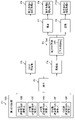
- FIG. 1 is a block diagram of a medical image diagnostic system according to this embodiment.
- FIG. 2 is a flow chart showing a medical image diagnosis method.
- FIG. 3 is a process diagram showing a medical image diagnosis method.
- FIG. 4 is a diagram showing a display form.
- FIG. 5 is a diagram showing a display form.
- FIG. 6 is a diagram showing a display form.
- FIG. 7 is a diagram showing a display form.
- the medical image diagnosis system reduces the burden on doctors when performing image diagnosis on a large number of medical images, such as in health examinations.
- FIG. 1 is a block diagram of a medical image diagnostic system 10 according to this embodiment.
- the medical image diagnostic system 10 includes a modality 12, an image storage server 14, each company's CAD (Computer-Aided Diagnosis) processing server 16, a result integration CAD processing server 18, a PACS (Picture Archiving and Communication System) viewer 20;
- CAD Computer-Aided Diagnosis
- PACS Physical Archiving and Communication System
- the modality 12, image storage server 14, company CAD processing server 16, result integration CAD processing server 18, and PACS viewer 20 are each connected to a communication network such as the Internet so that data can be sent and received.
- the modality 12 is an imaging device that captures an image of the inspection target site of the subject and generates a medical image.
- the modality 12 includes, for example, an X-ray imaging device, a CT (Computed Tomography) device, an MRI (Magnetic Resonance Imaging) device, a PET (Positron Emission Tomography) device, an ultrasonic device, and a CR (Computed Radiography) device using a plane X-ray detector. ) devices.
- the image storage server 14 is a server that manages medical images captured by the modality 12 .
- a computer having a large-capacity storage device is applied to the image storage server 14 .
- the computer incorporates software that provides the functionality of the data storage system.
- the image storage server 14 acquires medical images captured by the modality 12 and stores them in a large-capacity storage device.
- DICOM Digital Imaging and COmmunications in Medicine
- a medical image may be added with DICOM tag information defined in the DICOM standard.
- image in this specification can include the meaning of image data, which is a signal representing an image, in addition to the meaning of the image itself such as a photograph.
- Each company's CAD processing server 16 is composed of a plurality of CAD processing servers owned by a plurality of companies. Each company's CAD processing server 16 may be a single CAD processing server. Each company's CAD processing server 16 includes a first determination unit 16A.
- the first discriminating unit 16A executes an abnormality detection process for each organ with respect to the medical image acquired from the image storage server 14, and executes a first discrimination program for discriminating the presence or absence of one or more abnormalities from the medical image. include.
- Abnormalities include, for example, at least one of diseases, illnesses, and lesions.
- the first determination result of the first determination unit 16A is linked to the medical image in the image storage server 14 and stored in a large-capacity storage device.
- the first determination unit 16A may be provided in the result integration CAD processing server 18.
- the result integration CAD processing server 18 acquires and integrates the first determination results from the first determination unit 16A.
- the CAD results of different types of diseases, diseases, and lesions for the same organ in the same input image are integrated for the second determination unit 18A.
- the result integration CAD processing server 18 also includes a second determination unit 18A.
- the second determination unit 18A determines whether the medical images obtained from the image storage server 14 are normal and determined to have no abnormalities by the first determination unit 16A.
- a normal determination process is executed to determine whether or not each organ is normal. Whether or not the medical image is normal is, for example, whether or not the medical image can be said to be an image of a healthy person.
- a healthy person is a healthy person, eg, a person who is free from disease, disease, and lesions.
- the second determination result of the second determination unit 18A is linked to the medical image in the image storage server 14 and stored in the large-capacity storage device.
- the result integration CAD processing server 18 comprises a processor 18B and a memory 18C.
- Processor 18B executes instructions stored in memory 18C.
- the hardware structure of the processor 18B is various processors as shown below.
- Various processors include a CPU (Central Processing Unit), which is a general-purpose processor that executes software (programs) and acts as various functional units, a GPU (Graphics Processing Unit), which is a processor specialized for image processing, A circuit specially designed to execute specific processing such as PLD (Programmable Logic Device), which is a processor whose circuit configuration can be changed after manufacturing such as FPGA (Field Programmable Gate Array), ASIC (Application Specific Integrated Circuit), etc. Also included are dedicated electrical circuits, which are processors with configuration, and the like.
- One processing unit may be composed of one of these various processors, or two or more processors of the same or different type (for example, a plurality of FPGAs, a combination of CPU and FPGA, or a combination of CPU and GPU).
- a plurality of functional units may be configured by one processor.
- a single processor is configured by combining one or more CPUs and software.
- a processor acts as a plurality of functional units.
- SoC System On Chip
- various functional units are configured using one or more of the above various processors as a hardware structure.
- the hardware structure of these various processors is, more specifically, an electrical circuit that combines circuit elements such as semiconductor elements.
- the memory 18C stores instructions to be executed by the processor 18B.
- the memory 18C includes RAM (Random Access Memory) and ROM (Read Only Memory) (not shown).
- the processor 18B uses the RAM as a work area, executes software using various programs and parameters including a medical image processing program stored in the ROM, and uses the parameters stored in the ROM or the like to obtain the result Various processes of the integrated CAD processing server 18 are executed.
- the PACS viewer 20 is a terminal device used by a user such as a doctor, and for example, a known image viewer for interpretation is applied.
- PACS viewer 20 may be a personal computer, workstation, or tablet terminal.
- the PACS viewer 20 comprises an input device 20A and a display 20B.
- the input device 20A includes a pointing device such as a mouse and an input device such as a keyboard.
- a user can input instructions to the medical image diagnostic system 10 using the input device 20A.
- the display 20B displays screens required for operations on the input device 20A and functions as a part that implements a GUI (Graphical User Interface).
- a medical image captured by the modality 12 is displayed on the display 20B.
- the first determination result and the second determination result are displayed as CAD results on the display 20B.
- a touch panel display in which the input device 20A and the display 20B are integrated may be applied to the PACS viewer 20 .
- FIG. 2 is a flow chart showing a medical image diagnostic method using the medical image diagnostic system 10.
- FIG. 3 is a process diagram showing the medical image diagnosis method.
- the medical image diagnostic method is implemented by the processor 18B executing a medical image diagnostic program stored in the memory 18C.
- the medical image diagnostic program may be provided by a computer-readable non-transitory storage medium.
- the result integration CAD processing server 18 may read the medical image diagnostic program from the non-temporary storage medium and store it in the memory 18C.
- the medical image diagnostic method is performed for each organ of the subject.
- a case of diagnosing a lung CT image will be described.
- step S1 the processor 18B of the result integration CAD processing server 18 causes the image storage server 14 to acquire a CT image of the subject's lungs imaged by the modality 12.
- the image storage server 14 acquires CT images captured by the modality 12 .
- step S2 an example of the "first determination step”
- the processor 18B inputs the CT image acquired by the image storage server 14 to the CAD processing server 16 of each company.
- Each company's CAD processing server 16 inputs the CT image to the first determination unit 16A and performs the first determination (process P1).
- the first discrimination unit 16A includes a lesion detection AI 16B manufactured by Company A that detects disease ⁇ , a lesion detection AI 16C manufactured by Company A that detects disease ⁇ , and a lesion detection AI 16C manufactured by Company A that detects disease ⁇ .
- disease ⁇ is lung cancer
- disease ⁇ is pneumonia
- disease ⁇ is pneumothorax.
- Each of the lesion detection AIs 16B to 16F outputs a trained model (“first trained model”) that outputs a diseased area (lesion area, an example of “abnormality”) in the CT image when a lung CT image is input. ), each containing a convolutional neural network.
- first trained model that outputs a diseased area (lesion area, an example of “abnormality”) in the CT image when a lung CT image is input. )
- each containing a convolutional neural network each of the lesion detection AIs 16B to 16F is generated by performing deep learning on CT images of the lungs, using label images obtained by labeling each diseased region by a doctor as learning data.
- Each of the lesion detection AIs 16B to 16F is set to obtain the probability of each disease for each pixel of the CT image, and pixels exceeding a predetermined threshold are regarded as the region of the disease.
- Each of the lesion detection AIs 16B to 16F has a higher specificity than when lesion detection is performed independently, that is, the threshold is set relatively high. As a result, each of the lesion detection AIs 16B to 16F detects locations that are more likely to be lesions. This is because there are few abnormalities in physical examinations and the like, and even if there is an oversight, it is possible to determine that the image is not normal by the second determination in the second determination unit 18A.
- the lesion detection AI is not limited to the method of obtaining the disease probability of each pixel as described above. There may be.
- the first discrimination unit 16A inputs the CT image to each lesion detection AI 16B-16F.
- Each of the lesion detection AIs 16B to 16F performs lesion detection processing from the CT image and outputs the result as the first determination result.
- step S3 the processor 18B acquires and integrates the first determination results from the first determination unit 16A (process P2). Since integration is the same as described above, it will be omitted.
- step S4 the processor 18B determines whether or not there is an abnormality (here, lesion) in the CT image from the integrated first determination result.
- an abnormality here, lesion
- the process proceeds to step S5, and if there is no abnormality in the CT image (process P4), the process proceeds to step S6.
- step S5 the processor 18B causes the display 20B of the PACS viewer 20 to display the abnormal CT image in the display mode A, and the "first determination result" indicates that the CT image has an abnormality (" The post-processing of the processing form A is performed to make the doctor clearly recognize the first case (process P5). Further, the processor 18B adds the “type A” incidental information to the CT image, stores it in the image storage server 14, and ends the processing of this flowchart.
- step S6 an example of a "second discrimination step”
- the processor 18B inputs a CT image in which no abnormality exists to the second discrimination section 18A.
- the second determination unit 18A includes a normality determination AI 18D that determines whether the medical image is normal.
- the normal determination AI18D is a trained model (an example of a "second trained model") that determines whether or not a CT image of the lung is normal when it is input, and includes a convolutional neural network.
- the normal discrimination AI 18D is generated by deep learning using a learning data set of normal CT images and normal labels and a learning data set of abnormal CT images and abnormal labels.
- a normal CT image is a CT image of a healthy subject.
- a non-normal CT image is a CT image with some abnormality, such as a CT image of a person having at least one of disease, disease, and lesion.
- the normality determination AI 18D is generated to output the degree of normality of the input CT image as a numerical value (score, an example of "probability").
- the normality determination AI 18D outputs that the CT image is not normal when the degree of normality of the CT image is less than a predetermined threshold, and outputs that the CT image is normal when the degree of normality of the CT image is equal to or greater than the threshold.
- the second discrimination unit 18A inputs the CT image to the normal discrimination AI 18D and obtains a second discrimination result (process P6).
- step S7 the processor 18B determines whether the CT image is normal from the second determination result. If the CT image is not normal (an example of "second case", process P7), the process proceeds to step S8, and if the CT image is normal (an example of "third case", process P8), step Move to S9.
- step S8 the processor 18B causes the display 20B of the PACS viewer 20 to display the abnormal CT image in the display mode B, and unlike the "first case", the "first determination result” indicates that there is an abnormality.
- the post-processing of the processing mode B is performed to make the doctor clearly recognize that the CT image has an abnormality in the "second determination result" ("second case") (process P9).
- the processor 18B adds the “type B” incidental information to the CT image, stores it in the image storage server 14, and terminates the processing of this flowchart.
- step S9 the processor 18B causes the display 20B of the PACS viewer 20 to display the normal CT image in the display mode C, so that the doctor can process the "normal CT image" more easily.
- the post-processing of the processing form C is performed (process P10).
- the processor 18B adds the “type C” incidental information to the CT image, stores it in the image storage server 14, and ends the processing of this flowchart.
- the processor 18B causes the display 20B to display the diagnosis results based on the "first determination result” and the "second determination result” in display modes A, B, and display mode C, respectively.
- the processor 18B may cause the display 20B to display the diagnosis results in different modes for the display mode A and the display mode B, respectively.
- Different display items, descriptions, or display formats characters, drawings, colors, etc.
- Different diagnosis results can be displayed in the display form of .
- the display mode A the name of the detected lesion and its area are visually displayed in the same manner as in general CAD.
- display form B the doctor is notified that no lesion was detected, but the lesion was clearly not normal.
- display form C the fact that there is a high possibility that there is no abnormality is presented, the doctor's confirmation is skipped, and the fact that there is no abnormality is automatically reported to the patient.
- FIG. 4 is a diagram showing display form A.
- the CT image I1 is displayed on the display 20B, and the marker M1 surrounding the lesion area of the CT image I1 is superimposed on the CT image I1.
- an explanatory text T1 for the CT image I1 which is an explanatory text T1 for the lesion area surrounded by the markers M1, is displayed in the area on the right side of the CT image I1.
- the lesion area is detected by a lesion detection AI 16B manufactured by Company A that detects disease ⁇ (lung cancer), and the explanatory text T1 "Detected by lung cancer detection CAD manufactured by Company A " is displayed on the display 20B. .
- FIG. 5 is a diagram showing a display form B.
- FIG. 5 in display mode B, a CT image I2 is displayed on the display 20B, and a marker M2 surrounding the entire CT image I2 is superimposed on the CT image I2 .
- an explanatory text T2 related to the marker M2 which is the explanatory text T1 for the CT image I2 , is displayed in the area on the right side of the CT image I2 .
- an explanation T2 is displayed on the display 20B, stating, "No abnormality reported by each CAD. However, normal determination AI cannot confirm that the patient is healthy.”
- FIG. 6 is a diagram showing display form C. As shown in FIG. As shown in FIG. 6, in the display mode C, a CT image I3 is displayed on the display 20B. Further, in the display form C , an explanatory text T3 for the CT image I3 is displayed in the area on the right side of the CT image I3 . Here, the explanation T3 "No abnormality was found in CAD" is displayed on the display 20B. Since there is a high possibility that the CT image I3 is not abnormal, it is also possible to skip the doctor's confirmation by only displaying the fact that the CT image I3 is normal without displaying the CT image I3.
- the processor 18B allows the doctor to more easily confirm and judge the diagnosis results of the "first determination result” and the "second determination result” and to process the medical image.
- the processing mode A and the processing mode B, and the processing mode C are post-processed in different manners.
- processing mode C a flag is set that allows a simple check by a doctor
- processing mode A and processing mode B no flag is set.
- the display order of the interpretation/examination list for the doctor to check the medical images may be changed so that the CT images of the processing mode A and the CT images of the processing mode B are prioritized over the CT images of the processing mode C. good.
- the processor 18B may perform post-processing in different modes for the processing mode A and the processing mode B, respectively.
- the presence or absence of abnormality can be determined from the medical image in the first determination unit 16A. Further, when no abnormality is detected by the first determination unit 16A, it is possible to determine whether the medical image is normal by the second determination unit 18A. Therefore, it is possible to reduce the burden on doctors when performing image diagnosis on a large number of medical images.
- a third determination process may be performed to determine the presence or absence of abnormality from the medical image.
- the third discrimination process is performed with a sensitivity higher than that in the first discrimination process (with a specificity lower than that in the first discrimination process), that is, with a relatively low threshold.
- the third discrimination process is performed by the first discrimination section 16A.
- the first determination unit 16A performs the third determination process by setting the sensitivity of each of the lesion detection AIs 16B to 16F higher than in the first determination process, that is, by setting the threshold value relatively low.
- the third discrimination process extracts a lesion based on the evaluation criteria that it is acceptable even if a non-sickness is discriminated as a disease, and reports it to the doctor. Assuming that the display form in this case is display form D, it is desirable to present to the doctor that the lesion is extracted in display form D with increased sensitivity.
- FIG. 7 is a diagram showing a display form D.
- FIG. 7 in the display form D, the CT image I2 is displayed on the display 20B, the marker M2 surrounding the entire CT image I2 is superimposed on the CT image I2 , and the lesion of the CT image I2 is displayed.
- a marker M3 surrounding the region is superimposed on the CT image I2 .
- the marker M3 is displayed with a dashed line to indicate that it is a lesion detected with increased sensitivity.
- an explanatory text T4 related to the marker M3 which is the explanatory text T1 for the CT image I2 , is displayed in the area on the right side of the CT image I2 .
- an explanation T4 is displayed on the display 20B, stating that "the lung cancer is detected by the detection CAD manufactured by Company A as a result of the CAD processing being performed again with increased sensitivity because the patient is not healthy in the normal determination CAD.”
- a slider bar SB for setting the sensitivity of the first discrimination section 16A may be displayed in the display mode B.
- the third determination process may be performed with the set sensitivity, and the display form D as shown in FIG. 7 may be displayed.
- each of the lesion detection AIs 16B to 16F may extract any of liver cancer, multiple cysts, liver cirrhosis, and fatty liver from a CT image including the liver.
Landscapes
- Engineering & Computer Science (AREA)
- Health & Medical Sciences (AREA)
- Medical Informatics (AREA)
- General Health & Medical Sciences (AREA)
- Public Health (AREA)
- Epidemiology (AREA)
- Radiology & Medical Imaging (AREA)
- Primary Health Care (AREA)
- Nuclear Medicine, Radiotherapy & Molecular Imaging (AREA)
- Biomedical Technology (AREA)
- General Physics & Mathematics (AREA)
- Computer Vision & Pattern Recognition (AREA)
- Physics & Mathematics (AREA)
- Theoretical Computer Science (AREA)
- Databases & Information Systems (AREA)
- Pathology (AREA)
- Data Mining & Analysis (AREA)
- Quality & Reliability (AREA)
- Apparatus For Radiation Diagnosis (AREA)
Priority Applications (4)
| Application Number | Priority Date | Filing Date | Title |
|---|---|---|---|
| JP2023529712A JP7783889B2 (ja) | 2021-06-17 | 2022-05-24 | 医用画像診断システム、医用画像診断システムの作動方法及びプログラム |
| EP22824749.0A EP4358021A4 (en) | 2021-06-17 | 2022-05-24 | MEDICAL IMAGES DIAGNOSTIC SYSTEM, MEDICAL IMAGES DIAGNOSTIC PROCEDURES AND PROGRAM |
| US18/533,059 US20240112339A1 (en) | 2021-06-17 | 2023-12-07 | Medical image diagnosis system, medical image diagnosis method, and program |
| JP2025209173A JP2026020374A (ja) | 2021-06-17 | 2025-11-28 | 医用画像診断システム、医用画像診断システムの作動方法及びプログラム |
Applications Claiming Priority (2)
| Application Number | Priority Date | Filing Date | Title |
|---|---|---|---|
| JP2021100610 | 2021-06-17 | ||
| JP2021-100610 | 2021-06-17 |
Related Child Applications (1)
| Application Number | Title | Priority Date | Filing Date |
|---|---|---|---|
| US18/533,059 Continuation US20240112339A1 (en) | 2021-06-17 | 2023-12-07 | Medical image diagnosis system, medical image diagnosis method, and program |
Publications (1)
| Publication Number | Publication Date |
|---|---|
| WO2022264755A1 true WO2022264755A1 (ja) | 2022-12-22 |
Family
ID=84526167
Family Applications (1)
| Application Number | Title | Priority Date | Filing Date |
|---|---|---|---|
| PCT/JP2022/021219 Ceased WO2022264755A1 (ja) | 2021-06-17 | 2022-05-24 | 医用画像診断システム、医用画像診断方法及びプログラム |
Country Status (4)
| Country | Link |
|---|---|
| US (1) | US20240112339A1 (https=) |
| EP (1) | EP4358021A4 (https=) |
| JP (2) | JP7783889B2 (https=) |
| WO (1) | WO2022264755A1 (https=) |
Cited By (2)
| Publication number | Priority date | Publication date | Assignee | Title |
|---|---|---|---|---|
| WO2025180797A1 (de) * | 2024-02-28 | 2025-09-04 | Siemens Healthineers Ag | Computer-implementiertes verfahren, medizintechnisches system und computerprogrammprodukt zur automatischen medizinischen bildauswertung und/oder bildbefundung und deren verwendung |
| JP7792101B2 (ja) | 2023-06-01 | 2025-12-25 | ルニット・インコーポレイテッド | 人工知能基盤の医療映像分析方法およびシステム |
Families Citing this family (2)
| Publication number | Priority date | Publication date | Assignee | Title |
|---|---|---|---|---|
| USD1057759S1 (en) * | 2021-07-09 | 2025-01-14 | Mauna Kea Technologies | Display screen with transitional graphical user interface for medical imaging equipment |
| KR102389628B1 (ko) * | 2021-07-22 | 2022-04-26 | 주식회사 클라리파이 | 의료영상의 병변 특징에 따른 영상처리 장치 및 방법 |
Citations (5)
| Publication number | Priority date | Publication date | Assignee | Title |
|---|---|---|---|---|
| JP2006340835A (ja) | 2005-06-08 | 2006-12-21 | Konica Minolta Medical & Graphic Inc | 異常陰影候補の表示方法及び医用画像処理システム |
| JP2012026982A (ja) * | 2010-07-27 | 2012-02-09 | Panasonic Electric Works Sunx Co Ltd | 検査装置 |
| JP2019067069A (ja) * | 2017-09-29 | 2019-04-25 | アンリツ株式会社 | 異常検知装置及び異常検知方法並びに異常検知プログラム |
| US20200202103A1 (en) * | 2017-06-09 | 2020-06-25 | University Of Surrey | Method and Apparatus for Processing Retinal Images |
| JP6885517B1 (ja) * | 2020-03-17 | 2021-06-16 | 株式会社村田製作所 | 診断支援装置及びモデル生成装置 |
Family Cites Families (3)
| Publication number | Priority date | Publication date | Assignee | Title |
|---|---|---|---|---|
| CN109741812B (zh) * | 2017-10-30 | 2024-09-27 | 三星电子株式会社 | 发送医学图像的方法以及执行所述方法的医学成像设备 |
| CN113678147B (zh) * | 2019-04-09 | 2024-08-27 | 基诺媒体株式会社 | 搜索方法以及信息处理系统 |
| US11334994B2 (en) * | 2019-05-24 | 2022-05-17 | Lunit Inc. | Method for discriminating suspicious lesion in medical image, method for interpreting medical image, and computing device implementing the methods |
-
2022
- 2022-05-24 WO PCT/JP2022/021219 patent/WO2022264755A1/ja not_active Ceased
- 2022-05-24 JP JP2023529712A patent/JP7783889B2/ja active Active
- 2022-05-24 EP EP22824749.0A patent/EP4358021A4/en active Pending
-
2023
- 2023-12-07 US US18/533,059 patent/US20240112339A1/en active Pending
-
2025
- 2025-11-28 JP JP2025209173A patent/JP2026020374A/ja active Pending
Patent Citations (5)
| Publication number | Priority date | Publication date | Assignee | Title |
|---|---|---|---|---|
| JP2006340835A (ja) | 2005-06-08 | 2006-12-21 | Konica Minolta Medical & Graphic Inc | 異常陰影候補の表示方法及び医用画像処理システム |
| JP2012026982A (ja) * | 2010-07-27 | 2012-02-09 | Panasonic Electric Works Sunx Co Ltd | 検査装置 |
| US20200202103A1 (en) * | 2017-06-09 | 2020-06-25 | University Of Surrey | Method and Apparatus for Processing Retinal Images |
| JP2019067069A (ja) * | 2017-09-29 | 2019-04-25 | アンリツ株式会社 | 異常検知装置及び異常検知方法並びに異常検知プログラム |
| JP6885517B1 (ja) * | 2020-03-17 | 2021-06-16 | 株式会社村田製作所 | 診断支援装置及びモデル生成装置 |
Cited By (2)
| Publication number | Priority date | Publication date | Assignee | Title |
|---|---|---|---|---|
| JP7792101B2 (ja) | 2023-06-01 | 2025-12-25 | ルニット・インコーポレイテッド | 人工知能基盤の医療映像分析方法およびシステム |
| WO2025180797A1 (de) * | 2024-02-28 | 2025-09-04 | Siemens Healthineers Ag | Computer-implementiertes verfahren, medizintechnisches system und computerprogrammprodukt zur automatischen medizinischen bildauswertung und/oder bildbefundung und deren verwendung |
Also Published As
| Publication number | Publication date |
|---|---|
| JP7783889B2 (ja) | 2025-12-10 |
| EP4358021A4 (en) | 2024-10-09 |
| US20240112339A1 (en) | 2024-04-04 |
| JPWO2022264755A1 (https=) | 2022-12-22 |
| EP4358021A1 (en) | 2024-04-24 |
| JP2026020374A (ja) | 2026-02-06 |
Similar Documents
| Publication | Publication Date | Title |
|---|---|---|
| JP7783889B2 (ja) | 医用画像診断システム、医用画像診断システムの作動方法及びプログラム | |
| JP7524334B2 (ja) | 画像表示装置、方法およびプログラム | |
| JP7756107B2 (ja) | 画像表示装置、方法およびプログラム | |
| JP7237089B2 (ja) | 医療文書作成支援装置、方法およびプログラム | |
| WO2022070528A1 (ja) | 医用画像処理装置、方法およびプログラム | |
| US20230360213A1 (en) | Information processing apparatus, method, and program | |
| JP2026020375A (ja) | 医用画像診断システム、医用画像診断システムの作動方法及びプログラム | |
| US20210210206A1 (en) | Medical image diagnosis support device, method, and program | |
| US20220415484A1 (en) | Image processing apparatus, image display system, image processing method, and program | |
| WO2020241857A1 (ja) | 医療文書作成装置、方法およびプログラム、学習装置、方法およびプログラム、並びに学習済みモデル | |
| JP7833894B2 (ja) | 情報処理装置、情報処理システム、情報処理方法及びプログラム | |
| US12423809B2 (en) | Medical image processing apparatus, method, and program for detecting abnormal region by setting threshold | |
| JP2021175454A (ja) | 医用画像処理装置、方法およびプログラム | |
| US12512210B2 (en) | Medical image display apparatus, method, and program | |
| JP7735325B2 (ja) | 医用画像表示装置、方法およびプログラム | |
| US12278010B2 (en) | Medical image display apparatus, method, and program | |
| JP7483018B2 (ja) | 画像処理装置、画像処理方法及びプログラム、画像処理システム | |
| US12347560B2 (en) | Progression prediction apparatus, progression prediction method, and progression prediction program | |
| US20240105315A1 (en) | Medical image diagnostic system, medical image diagnostic system evaluation method, and program | |
| US20240290470A1 (en) | Medical information processing apparatus and medical information processing system |
Legal Events
| Date | Code | Title | Description |
|---|---|---|---|
| 121 | Ep: the epo has been informed by wipo that ep was designated in this application |
Ref document number: 22824749 Country of ref document: EP Kind code of ref document: A1 |
|
| WWE | Wipo information: entry into national phase |
Ref document number: 2023529712 Country of ref document: JP |
|
| WWE | Wipo information: entry into national phase |
Ref document number: 2022824749 Country of ref document: EP |
|
| NENP | Non-entry into the national phase |
Ref country code: DE |
|
| ENP | Entry into the national phase |
Ref document number: 2022824749 Country of ref document: EP Effective date: 20240117 |