WO2022264622A1 - 動画像符号化装置、動画像復号装置 - Google Patents
動画像符号化装置、動画像復号装置 Download PDFInfo
- Publication number
- WO2022264622A1 WO2022264622A1 PCT/JP2022/015302 JP2022015302W WO2022264622A1 WO 2022264622 A1 WO2022264622 A1 WO 2022264622A1 JP 2022015302 W JP2022015302 W JP 2022015302W WO 2022264622 A1 WO2022264622 A1 WO 2022264622A1
- Authority
- WO
- WIPO (PCT)
- Prior art keywords
- image
- unit
- prediction
- processing
- scaling
- Prior art date
- Legal status (The legal status is an assumption and is not a legal conclusion. Google has not performed a legal analysis and makes no representation as to the accuracy of the status listed.)
- Ceased
Links
Images







Classifications
-
- H—ELECTRICITY
- H04—ELECTRIC COMMUNICATION TECHNIQUE
- H04N—PICTORIAL COMMUNICATION, e.g. TELEVISION
- H04N19/00—Methods or arrangements for coding, decoding, compressing or decompressing digital video signals
- H04N19/50—Methods or arrangements for coding, decoding, compressing or decompressing digital video signals using predictive coding
- H04N19/503—Methods or arrangements for coding, decoding, compressing or decompressing digital video signals using predictive coding involving temporal prediction
-
- H—ELECTRICITY
- H04—ELECTRIC COMMUNICATION TECHNIQUE
- H04N—PICTORIAL COMMUNICATION, e.g. TELEVISION
- H04N19/00—Methods or arrangements for coding, decoding, compressing or decompressing digital video signals
- H04N19/50—Methods or arrangements for coding, decoding, compressing or decompressing digital video signals using predictive coding
- H04N19/59—Methods or arrangements for coding, decoding, compressing or decompressing digital video signals using predictive coding involving spatial sub-sampling or interpolation, e.g. alteration of picture size or resolution
-
- H—ELECTRICITY
- H04—ELECTRIC COMMUNICATION TECHNIQUE
- H04N—PICTORIAL COMMUNICATION, e.g. TELEVISION
- H04N19/00—Methods or arrangements for coding, decoding, compressing or decompressing digital video signals
- H04N19/85—Methods or arrangements for coding, decoding, compressing or decompressing digital video signals using pre-processing or post-processing specially adapted for video compression
Definitions
- Embodiments of the present invention relate to video encoding devices and decoding devices.
- a moving image encoding device that generates encoded data by encoding a moving image and a moving image that generates a decoded image by decoding the encoded data in order to efficiently transmit or record the moving image An image decoding device is used.
- Specific video encoding methods include H.264/AVC and H.265/HEVC (High-Efficiency Video Coding).
- the images (pictures) that make up the video are divided into slices obtained by dividing an image, and coding tree units (CTU: Coding Tree Units) obtained by dividing a slice. ), a coding unit obtained by dividing the coding tree unit (Coding Unit: CU)), and a transform unit obtained by dividing the coding unit (TU: Transform Unit), and encoded/decoded for each CU.
- CTU Coding Tree Units
- a predicted image is normally generated based on a locally decoded image obtained by encoding/decoding an input image, and the predicted image is generated from the input image (original image).
- the prediction error obtained by subtraction (sometimes called the "difference image” or “residual image”) is encoded.
- Inter-prediction and intra-prediction are methods for generating predicted images.
- Non-Patent Document 1 can be cited as a technique for video encoding and decoding in recent years.
- Non-Patent Document 1 defines RPR (Reference Picture Re-sampling) technology that enables variable image resolution encoding and decoding. Furthermore, Annex D of Non-Patent Document 1 defines additional enhancement information SEI for transmitting the properties of an image, the display method, the timing, etc. at the same time as the encoded data.
- RPR Reference Picture Re-sampling
- Non-Patent Document 2 and Non-Patent Document 3 a method of performing regression by a neural network (NN) based on scale information for coordinate information and bicubic interpolation in the feature layer of NN are used as methods for performing enlargement at an arbitrary magnification. A method for doing so is disclosed.
- NN neural network
- Non-Patent Document 2 and Non-Patent Document 3 have the problem of insufficient processing and image quality when used as an image encoding device or an image decoding device.
- the method of Non-Patent Document 2 is based on point-by-point processing, the processing is complicated and not suitable for picture- or block-by-block processing.
- the method of Non-Patent Document 3 depends on the size of the feature layer, there is a limit to the magnification that can be taken. In both cases, the processing corresponding to the magnification is insufficient, the performance is not sufficient, and there is a problem in handling the motion vector when applying to the reference image.
- a moving image decoding device includes a neural network that performs rational-multiple scaling and a prediction unit that includes an interpolation unit that performs rational-multiple interpolation, and the actual width and height of a reference image and the target image are
- the first scaling factor by the neural network and the second scaling factor by the interpolator are derived from the actual width and height of the above, and the first scaling by the neural network and the second scaling factor by the interpolator are derived.
- An interpolated image is derived using scaling.
- the parameters of the neural network can be switched according to the enlargement ratio, so there is an effect that a suitable image can be output. Also, by switching parameters after the conversion size is expanded, the memory size for switching parameters can be minimized.
- FIG. 1 is a schematic diagram showing the configuration of a moving image transmission system according to this embodiment
- FIG. 1 is a diagram showing the configuration of a transmitting device equipped with a moving image encoding device and a receiving device equipped with a moving image decoding device according to an embodiment
- FIG. PROD_A indicates a transmitting device equipped with a video encoding device
- PROD_B indicates a receiving device equipped with a video decoding device.
- 1 is a diagram showing configurations of a recording device equipped with a moving image encoding device and a reproducing device equipped with a moving image decoding device according to an embodiment
- FIG. 4 is a diagram showing a hierarchical structure of encoded data
- 4 is a conceptual diagram of an image to be processed in the moving image transmission system according to the embodiment
- FIG. 2 is a conceptual diagram showing an example of reference pictures and reference picture lists
- 1 is a schematic diagram showing the configuration of an image decoding device
- FIG. 4 is a flowchart for explaining schematic operations of the image decoding device
- FIG. 4 is a schematic diagram showing the configuration of an inter-prediction parameter deriving unit
- It is a schematic diagram which shows the structure of an inter prediction image production
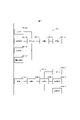
- FIG. 6 is a diagram showing the configuration of a neural network of NN filter section 611.
- FIG. 6 is a diagram showing an example of the configuration of NN filter section 611.
- FIG. 6 is a diagram showing an example of the configuration of NN filter section 611.
- FIG. 6 is a diagram showing an example of the configuration of NN filter section 611.
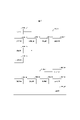
- FIG. 13 is a diagram showing an example of the configuration of an integer resolution conversion unit 6112I
- FIG. 11 is a diagram showing an example of the configuration of a rational number resolution converter 6112R
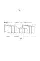
- FIG. 10 is a diagram showing processing units of the NN filter unit 611 and the rational number resolution conversion unit 6112R.
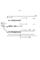
- FIG. 6 is a diagram showing an example of the configuration of NN filter section 611.
- FIG. 10 is a diagram showing an example of an input configuration of motion vectors of the NN filter unit 611.
- FIG. 6 is a diagram showing an example of the configuration of NN filter section 611.
- FIG. 6 is a diagram showing an example of the configuration of NN filter section 611.
- FIG. 10 is a diagram showing an example of the configuration of NN filter section 611.
- FIG. 1 is a schematic diagram showing the configuration of a moving image transmission system according to this embodiment.
- the moving image transmission system 1 is a system that transmits encoded data obtained by encoding images of different resolutions after resolution conversion, decodes the transmitted encoded data, inversely converts the image to the original resolution, and displays the image.
- a moving image transmission system 1 includes a moving image encoding device 10 , a network 21 , a moving image decoding device 30 and an image display device 41 .
- the video encoding device 10 is composed of a preprocessing device (preprocessing section) 51, an image encoding device (image encoding section) 11, and a synthetic information creating device (compositing information creating section) 71.
- the video decoding device 30 is composed of an image decoding device (image decoding section) 31 and a post-processing device (post-processing section) 61 .
- the preprocessing device 51 converts the resolution of the image T included in the moving image as necessary, and supplies the variable resolution moving image T2 including images of different resolutions to the image encoding device 11. Also, the preprocessing device 51 may supply the image coding device 11 with filter information indicating whether or not the resolution of the image is converted. When the information indicates resolution conversion, the video encoding device 10 sets 1 to ref_pic_resampling_enabled_flag, which will be described later. Then, it is coded in the sequence parameter set SPS (Sequence Parameter Set) of the coded data Te.
- SPS Sequence Parameter Set
- the synthesis information creation device 71 creates filter information based on the image T1 included in the moving image, and sends it to the image encoding device 11.
- a variable resolution image T2 is input to the image encoding device 11 .
- the image encoding device 11 uses the RPR framework to encode the image size information of the input image in units of PPS, and sends it to the image decoding device 31 .
- the network 21 transmits the encoded filter information and encoded data Te to the image decoding device 31. Part or all of the encoded filter information may be included in the encoded data Te as additional enhancement information SEI.
- the network 21 is the Internet, a Wide Area Network (WAN), a Local Area Network (LAN), or a combination thereof.
- the network 21 is not necessarily a two-way communication network, and may be a one-way communication network that transmits broadcast waves such as terrestrial digital broadcasting and satellite broadcasting. Also, the network 21 may be replaced by a storage medium such as a DVD (Digital Versatile Disc: registered trademark) or a BD (Blue-ray Disc: registered trademark) that records the encoded data Te.
- the image decoding device 31 decodes each of the encoded data Te transmitted by the network 21, generates a variable resolution decoded image, and supplies it to the post-processing device 61.
- the post-processing device 61 When the filter information indicates resolution conversion, the post-processing device 61 performs super-resolution processing using super-resolution model parameters based on the image size information included in the encoded data. Then, by inversely transforming the resolution-converted image, a decoded image of the original size is generated. If the filter information does not indicate resolution conversion, image restoration processing using model parameters for image restoration is performed. A decoded image with reduced coding noise is generated by performing image restoration processing.
- the image display device 41 displays all or part of one or more decoded images Td2 input from the post-processing device 61.
- the image display device 41 includes a display device such as a liquid crystal display or an organic EL (Electro-luminescence) display.
- the form of the display includes stationary, mobile, HMD, and the like.
- the image decoding device 31 has high processing power, it displays an image with high image quality, and when it has only lower processing power, it displays an image that does not require high processing power and display power.
- FIG. 5 is a conceptual diagram of an image to be processed in the moving image transmission system shown in FIG. 1, showing changes in resolution of the image over time. However, in FIG. 5, it is not distinguished whether the image is encoded or not.
- FIG. 5 shows an example in which an image is transmitted to the image decoding device 31 with its resolution lowered in the process of the moving image transmission system. As shown in FIG. 5, the image preprocessor 51 typically performs a transformation that reduces the resolution of the image in order to reduce the amount of information transmitted.
- x ? y : z is a ternary operator that takes y if x is true (other than 0) and z if x is false (0).
- abs(a) is a function that returns the absolute value of a.
- Int(a) is a function that returns the integer value of a.
- floor(a) is a function that returns the largest integer less than or equal to a.
- ceil(a) is a function that returns the smallest integer greater than or equal to a.
- a/d represents the division of a by d (truncated after the decimal point).
- FIG. 4 is a diagram showing the hierarchical structure of data in the encoded data Te.
- the encoded data Te illustratively includes a sequence and a plurality of pictures that constitute the sequence.
- FIG. 4 shows a coded video sequence defining a sequence SEQ, a coded picture defining a picture PICT, a coded slice defining a slice S, a coded slice data defining a slice data, and a coded slice data included in the coded slice data.
- a diagram showing a coding tree unit and coding units included in the coding tree unit is shown.
- the encoded video sequence defines a set of data that the image decoding device 31 refers to in order to decode the sequence SEQ to be processed.
- Sequence SEQ as shown in Figure 4, consists of video parameter set VPS (Video Parameter Set), sequence parameter set SPS (Sequence Parameter Set), picture parameter set PPS (Picture Parameter Set), adaptation parameter set (APS), picture PICT , and Supplemental Enhancement Information (SEI).
- VPS Video Parameter Set
- sequence parameter set SPS Sequence Parameter Set
- picture parameter set PPS Picture Parameter Set
- APS adaptation parameter set
- SEI Supplemental Enhancement Information
- a video parameter set VPS is a set of coding parameters common to multiple video images, a set of coding parameters common to multiple video images, and a set of coding parameters related to multiple layers and individual layers included in a video image. Sets are defined.
- the sequence parameter set SPS defines a set of encoding parameters that the image decoding device 31 refers to in order to decode the target sequence. For example, the width and height of the picture are defined. A plurality of SPSs may exist. In that case, one of a plurality of SPSs is selected from the PPS.
- the sequence parameter set SPS includes the following syntax elements.
- ref_pic_resampling_enabled_flag A flag that specifies whether or not to use a function that makes the resolution variable (resampling) when decoding each image included in a single sequence that references the target SPS.
- the flag is a flag that indicates that the size of the reference picture referred to in generating the predicted image changes between each image represented by a single sequence. If the value of the flag is 1, the above resampling is applied; if it is 0, it is not applied.
- pic_width_max_in_luma_samples A syntax element that specifies the width, in luma blocks, of the image with the largest width among the images in a single sequence.
- the value of the syntax element is required to be non-zero and an integral multiple of Max(8, MinCbSizeY).
- MinCbSizeY is a value determined by the minimum size of the luminance block.
- pic_height_max_in_luma_samples A syntax element that specifies the height of the image with the largest height among the images in a single sequence, in units of luma blocks. Also, the value of the syntax element is required to be non-zero and an integral multiple of Max(8, MinCbSizeY).
- sps_temporal_mvp_enabled_flag A flag that defines whether or not to use temporal motion vector prediction when decoding the target sequence.
- temporal motion vector prediction is used, and if the value is 0, temporal motion vector prediction is not used. Also, by specifying the flag, it is possible to prevent the coordinate position to be referred to from shifting when referring to reference pictures of different resolutions.
- the picture parameter set PPS defines a set of coding parameters that the image decoding device 31 refers to in order to decode each picture in the target sequence. For example, it includes a quantization width reference value (pic_init_qp_minus26) used for picture decoding and a flag (weighted_pred_flag) indicating application of weighted prediction.
- a plurality of PPSs may exist. In that case, one of a plurality of PPSs is selected from each picture in the target sequence.
- the picture parameter set PPS includes the following syntax elements.
- pic_width_in_luma_samples A syntax element that specifies the width of the target picture. The value of the syntax element is required to be not 0, but an integer multiple of Max(8, MinCbSizeY) and less than or equal to pic_width_max_in_luma_samples.
- pic_height_in_luma_samples A syntax element that specifies the height of the target picture. The value of the syntax element is required to be not 0, but an integer multiple of Max(8, MinCbSizeY) and less than or equal to pic_height_max_in_luma_samples.
- conformance_window_flag a flag indicating whether or not the conformance (cropping) window offset parameter is subsequently signaled.
- the conformance window offset parameter indicates where to display the conformance window. If the flag is 1, the parameter is signaled, and if it is 0, the parameter does not exist.
- conf_win_left_offset, conf_win_right_offset, conf_win_top_offset, conf_win_bottom_offset Offset values for specifying the left, right, top, and bottom positions of a picture output in decoding processing with respect to a rectangular area specified by picture coordinates for output.
- scaling_window_flag A flag indicating whether or not a scaling window offset parameter exists in the target PPS, and is a flag relating to regulation of the output image size. When this flag is 1, it indicates that the parameter exists in the PPS, and when this flag is 0, it indicates that the parameter does not exist in the PPS. Also, if the value of ref_pic_resampling_enabled_flag is 0, then the value of scaling_window_flag is also required to be 0.
- scaling_win_left_offset, scaling_win_right_offset, scaling_win_top_offset, scaling_win_bottom_offset Syntax elements that specify the offsets applied to the image size for scaling ratio calculations, in units of luminance samples, for the left, right, top, and bottom positions of the target picture, respectively. Also, if the value of scaling_window_flag is 0, the values of scaling_win_left_offset, scaling_win_right_offset, scaling_win_top_offset and scaling_win_bottom_offset are assumed to be 0.
- scaling_win_left_offset + scaling_win_right_offset is required to be less than pic_width_in_luma_samples
- the value of scaling_win_top_offset + scaling_win_bottom_offset is required to be less than pic_height_in_luma_samples.
- the output picture width PicOutputWidthL and height PicOutputHeightL are derived as follows.
- PicOutputWidthL pic_width_in_luma_samples - (scaling_win_right_offset + scaling_win_left_offset)
- PicOutputHeightL pic_height_in_luma_samples - (scaling_win_bottom_offset + scaling_win_top_offset) (coded picture)
- the encoded picture defines a set of data that the image decoding device 31 refers to in order to decode the picture PICT to be processed.
- a picture PICT includes a picture header PH, slice 0 to slice NS-1 (NS is the total number of slices included in the picture PICT).
- a picture header contains the following syntax elements: • pic_temporal_mvp_enabled_flag: A flag that defines whether or not to use temporal motion vector prediction for inter prediction of slices associated with the picture header. If the value of the flag is 0, the syntax elements of the slice associated with the picture header are restricted such that temporal motion vector prediction is not used in decoding the slice. If the value of the flag is 1, it indicates that temporal motion vector prediction is used for decoding the slice associated with the picture header. Also, if the flag is not specified, the value is assumed to be 0.
- the coded slice defines a set of data that the image decoding device 31 refers to in order to decode the slice S to be processed.
- a slice includes a slice header and slice data, as shown in FIG.
- the slice header contains a group of coding parameters that the image decoding device 31 refers to in order to determine the decoding method for the target slice.
- Slice type designation information (slice_type) that designates a slice type is an example of a coding parameter included in a slice header.
- Slice types that can be specified by the slice type specifying information include (1) an I slice that uses only intra prediction during encoding, (2) simple prediction (L0 prediction) or intra prediction that uses during encoding. (3) B slices using uni-prediction (L0 prediction or L1 prediction), bi-prediction, or intra-prediction in encoding.
- inter prediction is not limited to uni-prediction and bi-prediction, and a predicted image may be generated using more reference pictures.
- P and B slices they refer to slices containing blocks for which inter prediction can be used.
- the slice header may contain a reference (pic_parameter_set_id) to the picture parameter set PPS.
- the encoded slice data defines a set of data that the image decoding device 31 refers to in order to decode slice data to be processed.
- the slice data contains CTU, as shown in the encoded slice header in FIG.
- a CTU is a fixed-size (for example, 64x64) block that forms a slice, and is also called a largest coding unit (LCU).
- FIG. 4 defines a set of data that the image decoding device 31 refers to in order to decode the CTU to be processed.
- CTU uses recursive quad tree partitioning (QT (Quad Tree) partitioning), binary tree partitioning (BT (Binary Tree) partitioning), or ternary tree partitioning (TT (Ternary Tree) partitioning) to perform coding processing. It is divided into coding units CU, which are basic units. BT partitioning and TT partitioning are collectively called multi-tree partitioning (MT (Multi Tree) partitioning).
- MT Multi Tree partitioning
- a node of a tree structure obtained by recursive quadtree partitioning is called a coding node.
- Intermediate nodes of quadtrees, binary trees, and ternary trees are coding nodes, and the CTU itself is defined as the top-level coding node.
- CT includes, as CT information, a CU split flag (split_cu_flag) indicating whether or not to perform CT splitting, a QT split flag (qt_split_cu_flag) indicating whether or not to perform QT splitting, and an MT splitting direction indicating the splitting direction of MT splitting ( mtt_split_cu_vertical_flag), including MT split type (mtt_split_cu_binary_flag) indicating the split type of the MT split.
- split_cu_flag, qt_split_cu_flag, mtt_split_cu_vertical_flag and mtt_split_cu_binary_flag are transmitted for each encoding node.
- FIG. 4 defines a set of data that the image decoding device 31 refers to in order to decode the encoding unit to be processed.
- a CU is composed of a CU header CUH, prediction parameters, transform parameters, quantized transform coefficients, and the like.
- a prediction mode and the like are defined in the CU header.
- Prediction processing may be performed in units of CUs or in units of sub-CUs, which are subdivided into CUs. If the CU and sub-CU sizes are equal, there is one sub-CU in the CU. If the CU is larger than the sub-CU size, the CU is split into sub-CUs. For example, if the CU is 8x8 and the sub-CU is 4x4, the CU is divided into 4 sub-CUs consisting of 2 horizontal divisions and 2 vertical divisions.
- Intra prediction is prediction within the same picture
- inter prediction is prediction processing performed between different pictures (for example, between display times, between layer images).
- the transform/quantization process is performed in CU units, but the quantized transform coefficients may be entropy coded in subblock units such as 4x4.
- prediction parameter A predicted image is derived from the prediction parameters associated with the block.
- the prediction parameters include prediction parameters for intra prediction and inter prediction.
- the prediction parameters for inter prediction are described below.
- the inter prediction parameters are composed of prediction list usage flags predFlagL0 and predFlagL1, reference picture indices refIdxL0 and refIdxL1, and motion vectors mvL0 and mvL1.
- predFlagL0 and predFlagL1 are flags indicating whether or not reference picture lists (L0 list, L1 list) are used, and when the value is 1, the corresponding reference picture list is used.
- flag when the term "flag indicating whether or not it is XX" is used, when the flag is other than 0 (for example, 1), it is XX, and 0 is not XX. Treat 1 as true and 0 as false (same below).
- other values can be used as true and false values.
- inter-prediction parameters include, for example, affine flag affine_flag used in merge mode, merge flag merge_flag, merge index merge_idx, MMVD flag mmvd_flag, inter-prediction identifier for selecting reference pictures used in AMVP mode There are inter_pred_idc, reference picture index refIdxLX, predicted vector index mvp_LX_idx for deriving a motion vector, difference vector mvdLX, motion vector accuracy mode amvr_mode.
- a reference picture list is a list of reference pictures stored in the reference picture memory 306 .
- FIG. 6 is a conceptual diagram showing an example of reference pictures and reference picture lists.
- rectangles are pictures, arrows are picture reference relationships, the horizontal axis is time, I, P, and B in the rectangle are intra pictures, uni-predictive pictures, bi-predictive pictures, respectively.
- the numbers in the rectangles indicate the decoding order.
- the decoding order of the pictures is I0, P1, B2, B3, B4, and the display order is I0, B3, B2, B4, P1.
- FIG. 6 shows an example of a reference picture list for picture B3 (current picture).
- a reference picture list is a list representing reference picture candidates, and one picture (slice) may have one or more reference picture lists.
- the target picture B3 has two reference picture lists, an L0 list RefPicList0 and an L1 list RefPicList1.
- LX is a description method used when L0 prediction and L1 prediction are not distinguished, and hereinafter, parameters for the L0 list and parameters for the L1 list are distinguished by replacing LX with L0 and L1.
- merge prediction and AMVP prediction There are a merge prediction (merge) mode and an AMVP (Advanced Motion Vector Prediction, adaptive motion vector prediction) mode in prediction parameter decoding (encoding) methods, and merge_flag is a flag for identifying these.
- the merge prediction mode is a mode in which the prediction list usage flag predFlagLX, the reference picture index refIdxLX, and the motion vector mvLX are not included in the encoded data, but are derived from prediction parameters and the like of already processed neighboring blocks.
- AMVP mode is a mode in which inter_pred_idc, refIdxLX, and mvLX are included in encoded data.
- mvLX is encoded as mvp_LX_idx that identifies the prediction vector mvpLX and the difference vector mvdLX. Also, in addition to the merge prediction mode, there may be an affine prediction mode and an MMVD prediction mode.
- inter_pred_idc is a value that indicates the type and number of reference pictures, and takes one of PRED_L0, PRED_L1, and PRED_BI.
- PRED_L0 and PRED_L1 indicate uni-prediction using one reference picture managed by the L0 list and L1 list, respectively.
- PRED_BI indicates bi-prediction using two reference pictures managed by the L0 list and L1 list.
- merge_idx is an index that indicates which prediction parameter is to be used as the prediction parameter for the target block among the prediction parameter candidates (merge candidates) derived from the blocks for which processing has been completed.
- (motion vector) mvLX indicates the amount of shift between blocks on two different pictures.
- a prediction vector and a difference vector for mvLX are called mvpLX and mvdLX, respectively.
- inter_pred_idc Inter prediction identifier inter_pred_idc and prediction list usage flag predFlagLX
- inter_pred_idc The relationships between inter_pred_idc, predFlagL0, and predFlagL1 are as follows, and can be mutually converted.
- the configuration of the image decoding device 31 (FIG. 7) according to this embodiment will be described.
- the image decoding device 31 includes an entropy decoding unit 301, a parameter decoding unit (prediction image decoding device) 302, a loop filter 305, a reference picture memory 306, a prediction parameter memory 307, a prediction image generation unit (prediction image generation device) 308, an inverse quantum It includes a normalization/inverse transformation unit 311 , an addition unit 312 , and a prediction parameter derivation unit 320 .
- the image decoding device 31 may have a configuration in which the loop filter 305 is not included in accordance with the image encoding device 11 described later.
- the parameter decoding unit 302 further includes a header decoding unit 3020, a CT information decoding unit 3021, and a CU decoding unit 3022 (prediction mode decoding unit), and the CU decoding unit 3022 further includes a TU decoding unit 3024. These may be collectively called a decoding module.
- Header decoding section 3020 decodes parameter set information such as VPS, SPS, PPS, and APS, and slice headers (slice information) from encoded data.
- CT information decoding section 3021 decodes CT from encoded data.
- a CU decoding unit 3022 decodes a CU from encoded data.
- TU decoding section 3024 decodes QP update information (quantization correction value) and quantization prediction error (residual_coding) from encoded data when prediction error is included in TU.
- the predicted image generation unit 308 includes an inter predicted image generation unit 309 and an intra predicted image generation unit 310.
- the prediction parameter derivation unit 320 includes an inter prediction parameter derivation unit 303 and an intra prediction parameter derivation unit 304.
- CTU and CU as processing units
- processing may be performed in sub-CU units.
- CTU and CU may be read as blocks
- sub-CU may be read as sub-blocks
- processing may be performed in units of blocks or sub-blocks.
- the entropy decoding unit 301 performs entropy decoding on the encoded data Te input from the outside to decode individual codes (syntax elements).
- the entropy decoding unit 301 outputs the decoded code to the parameter decoding unit 302.
- the decoded codes are, for example, prediction modes predMode, merge_flag, merge_idx, inter_pred_idc, refIdxLX, mvp_LX_idx, mvdLX, amvr_mode, and the like. Control of which code is to be decoded is performed based on an instruction from parameter decoding section 302 .
- FIG. 8 is a flowchart for explaining a schematic operation of the image decoding device 31. As shown in FIG.
- the header decoding unit 3020 decodes parameter set information such as VPS, SPS, and PPS from the encoded data.
- the header decoding unit 3020 decodes the slice header (slice information) from the encoded data.
- the image decoding device 31 derives a decoded image of each CTU by repeating the processing from S1300 to S5000 for each CTU included in the target picture.
- the CT information decoding unit 3021 decodes the CTU from the encoded data.
- the CT information decoding unit 3021 decodes the CT from the encoded data.
- the CU decoding unit 3022 performs S1510 and S1520 to decode the CU from the encoded data.
- the CU decoding unit 3022 decodes CU information, prediction information, TU split flag split_transform_flag, CU residual flags cbf_cb, cbf_cr, cbf_luma, etc. from the encoded data.
- TU decoding section 3024 decodes QP update information, quantized prediction error, and transform index mts_idx from encoded data when prediction error is included in TU.
- the QP update information is a difference value from the quantization parameter prediction value qPpred, which is the prediction value of the quantization parameter QP.
- the predicted image generation unit 308 generates a predicted image based on the prediction information for each block included in the target CU.
- the inverse quantization/inverse transform unit 311 executes inverse quantization/inverse transform processing for each TU included in the target CU.
- the addition unit 312 adds the predicted image supplied from the predicted image generation unit 308 and the prediction error supplied from the inverse quantization/inverse transform unit 311, thereby decoding the target CU. Generate an image.
- the loop filter 305 applies a loop filter such as a deblocking filter, SAO, and ALF to the decoded image to generate a decoded image.
- a loop filter such as a deblocking filter, SAO, and ALF
- FIG. 9 shows a schematic diagram showing the configuration of the inter prediction parameter derivation unit 303 according to this embodiment.
- Inter prediction parameter derivation section 303 derives inter prediction parameters by referring to prediction parameters stored in prediction parameter memory 307 based on syntax elements input from parameter decoding section 302 . Also, inter prediction parameters are output to inter prediction image generation section 309 and prediction parameter memory 307 .
- the inter prediction parameter derivation unit 303 and its internal elements, the AMVP prediction parameter derivation unit 3032, the merge prediction parameter derivation unit 3036, the affine prediction unit 30372, the MMVD prediction unit 30373, the GPM unit 30377, the DMVR unit 30537, and the MV addition unit 3038 are , image encoding device, and image decoding device, they may be collectively referred to as a motion vector derivation unit (motion vector derivation device).
- the scale parameter derivation unit 30378 calculates the reference picture horizontal scaling ratio RefPicScale[i][j][0], the reference picture vertical scaling ratio RefPicScale[i][j][1], and the reference picture scaling ratio RefPicScale[i][j][1].
- Derive RefPicIsScaled[i][j] that indicates whether the picture is scaled or not.
- i indicates whether the reference picture list is the L0 list or the L1 list
- j is the value of the L0 reference picture list or the L1 reference picture list, and is derived as follows.
- (RefPicScale[i][j][1] ! (1 ⁇ 14))
- the variable PicOutputWidthL is the value used to calculate the horizontal scaling ratio when the coded picture is referenced, and is the number of horizontal pixels of luminance in the coded picture minus the left and right offset values.
- the variable PicOutputHeightL is a value used when calculating the vertical scaling ratio when a coded picture is referenced, and the value obtained by subtracting the vertical offset value from the number of luminance pixels in the vertical direction of the coded picture is used.
- the variable fRefWidth is the value of PicOutputWidthL of the reference picture of reference list value j of list i
- the variable fRefHight is the value of PicOutputHeightL of the reference picture of reference picture list value j of list i.
- scaling factor ScalingFactor
- scaling ratio scaling ratio RefPicScale
- the MMVD prediction unit 30373 derives an inter prediction parameter from the merge candidate and the difference vector derived by the merge prediction parameter derivation unit 3036.
- the GPM unit 30377 derives GPM parameters.
- merge_idx is derived and output to the merge prediction parameter derivation unit 3036.
- the AMVP prediction parameter derivation unit 3032 derives mvpLX from inter_pred_idc, refIdxLX or mvp_LX_idx.
- the MV adder 3038 adds the derived mvpLX and mvdLX to derive mvLX.
- the affine prediction unit 30372 1) derives motion vectors of two control points CP0, CP1 or three control points CP0, CP1, CP2 of the target block, 2) derives affine prediction parameters of the target block, and 3) A motion vector for each sub-block is derived from the affine prediction parameters.
- the merge prediction parameter derivation unit 3036 derives the prediction parameters of the target block using the prediction parameters (mvLX, refIdxLX, etc.) of spatially neighboring blocks or temporally neighboring blocks of the target block.
- the DMVR unit 30375 performs DMVR (Decoder side Motion Vector Refinement) processing.
- merge_flag is 1 or skip flag skip_flag is 1 for the target CU
- the DMVR unit 30375 modifies the motion vector mvLX of the target CU.
- mvLX is corrected using a predicted image derived from two reference pictures and motion vectors.
- the mvLX after correction is supplied to the inter prediction image generation unit 309 .
- AMVP prediction parameter derivation section 3032 selects motion vector mvpListLX[mvp_LX_idx] indicated by mvp_LX_idx from among the prediction vector candidates as mvpLX, and outputs it to MV addition section 3038 .
- MV adding section 3038 adds mvpLX input from AMVP prediction parameter deriving section 3032 and decoded mvdLX to calculate mvLX. Addition section 3038 outputs calculated mvLX to inter prediction image generation section 309 and prediction parameter memory 307 .
- a loop filter 305 is a filter provided in the encoding loop, and is a filter that removes block distortion and ringing distortion to improve image quality.
- a loop filter 305 applies filters such as a deblocking filter, a sample adaptive offset (SAO), and an adaptive loop filter (ALF) to the decoded image of the CU generated by the addition unit 312 .
- the reference picture memory 306 stores the decoded image of the CU in a predetermined position for each target picture and target CU.
- the prediction parameter memory 307 stores prediction parameters in predetermined positions for each CTU or CU. Specifically, the prediction parameter memory 307 stores the parameters decoded by the parameter decoding unit 302, the parameters derived by the prediction parameter deriving unit 320, and the like.
- the parameters derived by the prediction parameter derivation unit 320 are input to the prediction image generation unit 308 .
- the predicted image generation unit 308 reads a reference picture from the reference picture memory 306 .
- a predicted image generation unit 308 generates a predicted image of a block or sub-block using parameters and a reference picture (reference picture block) in a prediction mode indicated by predMode.
- a reference picture block is a set of pixels on a reference picture (usually rectangular and therefore called a block), and is an area referred to for generating a prediction image.
- Inter prediction image generator 309 When predMode indicates the inter prediction mode, inter prediction image generation section 309 generates a prediction image of a block or sub-block by inter prediction using inter prediction parameters and reference pictures input from inter prediction parameter derivation section 303 .
- FIG. 10 is a schematic diagram showing the configuration of the inter predicted image generation unit 309 included in the predicted image generation unit 308 according to this embodiment.
- the inter predicted image generation unit 309 includes a motion compensation unit (predicted image generation device) 3091 and a synthesizing unit 3095 .
- the synthesizing section 3095 includes an IntraInter synthesizing section 30951 , a GPM synthesizing section 30952 , a BDOF section 30954 and a weight prediction section 3094 .
- the motion compensation unit 3091 (interpolated image generation unit 3091) performs interpolation by reading reference blocks from the reference picture memory 306 based on the inter prediction parameters (predFlagLX, refIdxLX, mvLX) input from the inter prediction parameter derivation unit 303. Generate an image (motion compensated image).
- the reference block is a block on the reference picture RefPicLX specified by refIdxLX, which is shifted by mvLX from the position of the target block.
- refIdxLX a filter that is shifted by mvLX from the position of the target block.
- an interpolated image is generated by applying a filter called a motion compensation filter for generating pixels at decimal positions.
- the motion compensation unit 3091 uses the reference picture horizontal scaling ratio RefPicScale[i][j][0] derived by the scale parameter deriving unit 30378 and the reference picture vertical scaling ratio RefPicScale[i] It has a function to scale the interpolated image according to [j][1].
- the above processing may be performed by the NN filter unit 611 included in the motion compensation unit 3091 and further by the interpolation unit 6114 .
- the synthesizing unit 3095 includes an IntraInter synthesizing unit 30951, a GPM synthesizing unit 30952, a weight predicting unit 3094, and a BDOF unit 30954.
- the IntraInter synthesizing unit 30951 generates a predicted image by weighted sum of the inter predicted image and the intra predicted image.
- the GPM synthesizing unit 30952 generates a predicted image using the GPM described above.
- the BDOF unit 30954 refers to two predicted images (first predicted image and second predicted image) and a gradient correction term to generate a predicted image in bi-predictive mode.
- the weight prediction unit 3094 performs weight prediction from the interpolated image PredLX to generate a block prediction image pbSamples.
- the intra prediction image generation unit 310 performs intra prediction using the intra prediction parameters input from the intra prediction parameter derivation unit 304 and the reference pixels read from the reference picture memory 306 when the predMode indicates the intra prediction mode.
- the inverse quantization/inverse transform unit 311 inversely quantizes the quantized transform coefficients input from the parameter decoding unit 302 to obtain transform coefficients.
- the addition unit 312 adds the predicted image of the block input from the predicted image generation unit 308 and the prediction error input from the inverse quantization/inverse transform unit 311 for each pixel to generate a decoded image of the block.
- the adder 312 stores the decoded image of the block in the reference picture memory 306 and also outputs it to the loop filter 305 .
- the inverse quantization/inverse transform unit 311 inversely quantizes the quantized transform coefficients input from the parameter decoding unit 302 to obtain transform coefficients.
- the addition unit 312 adds the predicted image of the block input from the predicted image generation unit 308 and the prediction error input from the inverse quantization/inverse transform unit 311 for each pixel to generate a decoded image of the block.
- the adder 312 stores the decoded image of the block in the reference picture memory 306 and also outputs it to the loop filter 305 .
- FIG. 11 is a block diagram showing the configuration of the image encoding device 11 according to this embodiment.
- the image coding device 11 includes a predicted image generation unit 101, a subtraction unit 102, a transform/quantization unit 103, an inverse quantization/inverse transform unit 105, an addition unit 106, a loop filter 107, a prediction parameter memory (prediction parameter storage unit, frame memory) 108, reference picture memory (reference image storage unit, frame memory) 109, coding parameter determination unit 110, parameter coding unit 111, prediction parameter derivation unit 120, and entropy coding unit 104.
- the predicted image generation unit 101 generates a predicted image for each CU.
- the predicted image generation unit 101 includes the already described inter predicted image generation unit 309 and intra predicted image generation unit 310, and the description thereof will be omitted.
- the subtraction unit 102 subtracts the pixel values of the predicted image of the block input from the predicted image generation unit 101 from the pixel values of the image T to generate prediction errors.
- Subtraction section 102 outputs the prediction error to transform/quantization section 103 .
- the transform/quantization unit 103 calculates transform coefficients by frequency transforming the prediction error input from the subtraction unit 102, and derives quantized transform coefficients by quantization.
- the transform/quantization unit 103 outputs the quantized transform coefficients to the parameter coding unit 111 and the inverse quantization/inverse transform unit 105 .
- the inverse quantization/inverse transform unit 105 is the same as the inverse quantization/inverse transform unit 311 (FIG. 7) in the image decoding device 31, and description thereof is omitted.
- the calculated prediction error is output to addition section 106 .
- the parameter encoding unit 111 includes a header encoding unit 1110, a CT information encoding unit 1111, and a CU encoding unit 1112 (prediction mode encoding unit).
- CU encoding section 1112 further comprises TU encoding section 1114 . The general operation of each module will be described below.
- a header encoding unit 1110 performs encoding processing of parameters such as filter information, header information, division information, prediction information, and quantized transform coefficients.
- a CT information encoding unit 1111 encodes QT, MT (BT, TT) division information and the like.
- a CU encoding unit 1112 encodes CU information, prediction information, division information, and the like.
- the TU encoding unit 1114 encodes the QP update information and the quantized prediction error when the TU contains the prediction error.
- the CT information encoding unit 1111 and the CU encoding unit 1112 use inter prediction parameters (predMode, merge_flag, merge_idx, inter_pred_idc, refIdxLX, mvp_LX_idx, mvdLX), intra prediction parameters (intra_luma_mpm_flag, intra_luma_mpm_idx, intra_luma_mpm_reminder, intra_chroma_pred_mode), quantization transform coefficients, and other syntax elements to the parameter encoding unit 111.
- inter prediction parameters predMode, merge_flag, merge_idx, inter_pred_idc, refIdxLX, mvp_LX_idx, mvdLX
- intra prediction parameters intra prediction parameters
- intra prediction parameters intra prediction parameters
- intra prediction parameters intra prediction parameters
- the entropy coding unit 104 receives input from the parameter coding unit 111 of the quantized transform coefficients and coding parameters (division information, prediction parameters). The entropy encoding unit 104 entropy-encodes these to generate and output encoded data Te.
- Prediction parameter derivation unit 120 is means including inter prediction parameter encoding unit 112 and intra prediction parameter encoding unit 113, and derives intra prediction parameters and intra prediction parameters from the parameters input from encoding parameter determination unit 110. .
- the derived intra prediction parameters and intra prediction parameters are output to parameter coding section 111 .
- Inter prediction parameter encoding section 112 is configured including parameter encoding control section 1121 and inter prediction parameter deriving section 303 .
- the inter-prediction parameter deriving unit 303 has a common configuration with the image decoding device.
- Parameter encoding control section 1121 includes merge index derivation section 11211 and vector candidate index derivation section 11212 .
- the merge index derivation unit 11211 derives merge candidates and the like, and outputs them to the inter prediction parameter derivation unit 303.
- Vector candidate index derivation section 11212 derives vector prediction candidates and the like, and outputs them to inter prediction parameter derivation section 303 and parameter coding section 111 .
- Intra prediction parameter encoding section 113 includes parameter encoding control section 1131 and intra prediction parameter deriving section 304 .
- the intra-prediction parameter derivation unit 304 has a common configuration with the image decoding device.
- the parameter encoding control unit 1131 derives IntraPredModeY and IntraPredModeC. Furthermore, refer to mpmCandList[] to determine intra_luma_mpm_flag. These prediction parameters are output to intra prediction parameter derivation section 304 and parameter coding section 111 .
- the inputs to the inter prediction parameter derivation unit 303 and the intra prediction parameter derivation unit 304 are the coding parameter determination unit 110 and the prediction parameter memory 108, and are output to the parameter coding unit 111.
- the addition unit 106 adds pixel values of the prediction block input from the prediction image generation unit 101 and prediction errors input from the inverse quantization/inverse transformation unit 105 for each pixel to generate a decoded image.
- the addition unit 106 stores the generated decoded image in the reference picture memory 109 .
- a loop filter 107 applies a deblocking filter, SAO, and ALF to the decoded image generated by the addition unit 106.
- the loop filter 107 does not necessarily include the three types of filters described above, and may be configured with only a deblocking filter, for example.
- the prediction parameter memory 108 stores the prediction parameters generated by the coding parameter determination unit 110 in predetermined positions for each current picture and CU.
- the reference picture memory 109 stores the decoded image generated by the loop filter 107 in a predetermined position for each target picture and CU.
- the coding parameter determination unit 110 selects one set from a plurality of sets of coding parameters.
- the coding parameter is the above-described QT, BT or TT division information, prediction parameters, or parameters to be coded generated in relation to these.
- the predicted image generating unit 101 generates predicted images using these coding parameters.
- the coding parameter determination unit 110 calculates an RD cost value indicating the magnitude of the information amount and the coding error for each of the multiple sets.
- the RD cost value is, for example, the sum of the code amount and the value obtained by multiplying the squared error by the coefficient ⁇ .
- the code amount is the information amount of the encoded data Te obtained by entropy-encoding the quantization error and the encoding parameter.
- the squared error is the sum of squares of the prediction errors calculated in subtraction section 102 .
- the coefficient ⁇ is a preset real number greater than zero. Coding parameter determination section 110 selects a set of coding parameters that minimizes the calculated cost value. Coding parameter determination section 110 outputs the determined coding parameters to parameter coding section 111 and prediction parameter derivation section 120 .
- part of the image encoding device 11 and the image decoding device 31 in the above-described embodiment for example, the entropy decoding unit 301, the parameter decoding unit 302, the loop filter 305, the prediction image generation unit 308, the inverse quantization/inverse transform unit 311, addition unit 312, prediction parameter derivation unit 320, prediction image generation unit 101, subtraction unit 102, transformation/quantization unit 103, entropy coding unit 104, inverse quantization/inverse transformation unit 105, loop filter 107, coding
- the parameter determining unit 110, the parameter encoding unit 111, and the prediction parameter deriving unit 120 may be implemented by a computer.
- a program for realizing this control function may be recorded in a computer-readable recording medium, and the program recorded in this recording medium may be read into a computer system and executed.
- the “computer system” here is a computer system built into either the image encoding device 11 or the image decoding device 31, and includes hardware such as an OS and peripheral devices.
- the term "computer-readable recording medium” refers to portable media such as flexible discs, magneto-optical discs, ROMs and CD-ROMs, and storage devices such as hard disks built into computer systems.
- “computer-readable recording medium” means a medium that dynamically stores a program for a short period of time, such as a communication line for transmitting a program via a network such as the Internet or a communication line such as a telephone line. In that case, it may also include a memory that holds the program for a certain period of time, such as a volatile memory inside a computer system that serves as a server or client. Further, the program may be for realizing part of the functions described above, or may be capable of realizing the functions described above in combination with a program already recorded in the computer system.
- part or all of the image encoding device 11 and the image decoding device 31 in the above-described embodiment may be realized as an integrated circuit such as LSI (Large Scale Integration).
- LSI Large Scale Integration
- Each functional block of the image encoding device 11 and the image decoding device 31 may be individually processorized, or part or all of them may be integrated and processorized.
- the method of circuit integration is not limited to LSI, but may be realized by a dedicated circuit or a general-purpose processor.
- an integrated circuit based on this technology may be used.
- FIG. 12 is a diagram showing the configuration of the neural network filter section (NN filter section 611).
- the NN filter unit 611 is a means for performing filter processing on an input image using a neural network, and at the same time, performs reduction/enlargement by 1:1 or rational number times.
- the NN filter unit may be used as a loop filter applied to a reference image, a predicted image generation process from a reference image, or a post-filter for an output image.
- Fig. 12(a) is a configuration example of a loop filter.
- the loop filter 305 of the video decoding device (the loop filter 107 of the video encoding device) includes the NN filter unit 611 .
- the NN filter unit 611 filters the image in the reference picture memory 306/106 and stores it in the reference picture memory 306/106.
- the loop filter may comprise DF, ALF, SAO, bilateral filters, and the like.
- FIG. 12(b) is a configuration example of the predicted image generation unit.
- the inter prediction image generation unit 309 of the video decoding device and the video encoding device includes the NN filter unit 611 .
- the NN filter unit 611 reads out the image in the reference picture memory 306/106 and filters it to generate a prediction image.
- the predicted image may be further used for CIIP prediction, GPM prediction, weight prediction, and BDOF in the synthesizing section 3095, or may be directly output to the addition section 312 (the subtraction section 102 in the encoding device).
- FIG. 12(c) is a configuration example of a postfilter.
- a post-processing unit 61 after the video decoding device includes an NN filter unit 611 .
- the NN filter unit 611 processes the image in the reference picture memory 306 and outputs it to the outside.
- the output image may be displayed, written to a file, re-encoded (transcoded), transmitted, and the like.
- FIG. 13 shows an example of the neural network structure of the NN filter section 611.
- the NN filter unit 611 is composed of a neural network (feature extraction structure) 1700 and a neural network OutputBlock 1701 .
- Neural network 1700 performs processing at the same size.
- OutputBlock 1701 may perform resolution conversion.
- Neural network 1700 further comprises InputBlock 1702 and a plurality of Residual Blocks (ResBlocks) 1703 .
- InputBlock 1702 consists of a convolution layer (Conv) and an activation layer (Act).
- ResBlock 1703 consists of Conv and Act.
- the OutputBlock 1701 consists of Conv, a Resampling section (Resample) 1704, and a feature extraction layer 1705 (Act, Conv).
- Resample 1704 may convert the width and height of the feature vector output from feature extraction structure 1700 to the width and height of the output.
- Resample 1704 may be bilinear, bicubic, PixelShuffle, deconvolution, etc.
- Resample 1704 may change the enlargement ratio by scale_factor.
- the feature extraction layer 1705 generates an output image having the same channel, width and height as the input image from the enlarged feature vector.
- the NN filter unit 611 calculates the top left coordinates (xRef, yRef) of the input image by the following equation. can be derived.
- xRef xSb * scalingRatio[0]
- yRef ySb * scalingRatio[1]
- integer coordinates (xIntL, yIntL) and phase (xFracL, yFracL), which are decimal coordinates, may be derived below.
- the intermediate coordinates may be derived as follows.
- refxL (refxSbL>>14) + ((xL * scalingRatio[0])>>10)
- refyL (refySbL>>14) + ((yL * scalingRatio[1])>>10)
- refxL ((refxSbL >>8)>>6)
- refyL ((refySbL >>8)>>6) + ((yL * scalingRatio[1])>>4)>>6
- refyL ((refySbL >>8)>>6) + ((yL * scalingRatio[1])>>4)>>6
- the motion vector (refMxLX[0], refMvLX[1]) may be input to the NN filter unit 611, or the phase component of the motion vector (xFracL, yFracL), the phase component is also called the fractional component.
- FIG. 14 is a diagram showing an example of the configuration of NN filter section 611.
- the NN filter section 611 is composed of a first uniform resolution processing section 6111 , a resolution conversion processing section 6112 and a second uniform resolution processing section 6113 .
- the first uniform resolution processing unit 6111 is a neural network that outputs an image of output size (W, H) for an image of input size (W, H).
- W, H output size
- W, H input size
- it is configured using Conv, Act, addition for difference, and the like.
- “same resolution” means that the input and output have the same width and height, and the number of channels may be changed.
- an intermediate network with a smaller width and height than the input and output may be used in a branching network using a so-called UNET structure (a structure with paths that shrink and expand in addition to a unity structure).
- UNET structure a structure with paths that shrink and expand in addition to a unity structure.
- C x H x W in the figure indicates a tensor (three-dimensional array) with C channels, height H, and width W.
- B x C x H x W indicates a tensor (four-dimensional array) with batch number B, channel number C, height H, and width W.
- the number of input channels C1 and the number of output channels C2 of the first uniform resolution processing unit 6111 are set so that C2>C1, and it is preferable to increase the number of channels in order to obtain good characteristics.
- the resolution conversion processing unit 6112 is a neural network that outputs an image with an output size (m*W, n*H) obtained by multiplying the input size (W, H) by m times horizontally and n times vertically.
- the second uniform resolution processing unit 6113 is a neural network that outputs an image of output size (m*W, n*H) for an image of input size (m*W, n*H).
- the number of input channels C3 and the number of output channels C4 of the second uniform resolution processing unit 6113 are preferably C3>C4.
- the NN filter unit 611 may switch parameters of the neural network used in the second uniform resolution processing unit 6113, such as weights and biases, according to the values of the enlargement ratios m and n. For example, derive scaleIdx according to m and n, and copy the underlying model parameters BaseModel[scaleIdx][i] to Model according to scaleIdx and index i. Then, using the derived model, neural network processing may be performed.
- Model[i] BaseModel[scaleIdxM][scaleIdxN][i]
- the horizontal scaling factor m and the vertical scaling factor n may be combined for derivation.
- Model[i] BaseModel[scaleIdx][i] Alternatively, only the bias may be switched. Bias and BaseBias below mean the bias part of the NN parameters.
- the parameters of the neural network are switched according to the enlargement ratio, there is an effect that a suitable image can be output. Also, by switching parameters after the conversion size is expanded, the memory size for switching parameters can be minimized.
- the scales m and n are input as inputs to the second uniform resolution processing unit 6113, and adaptively processed.
- it may be configured to input m and n as one of the channels of the input image.
- the structure may be such that the scale is concatenated with the channel of the intermediate layer.
- the NN filter unit 611 may switch parameters of the neural network used in the second uniform resolution processing unit 6113, such as weight and bias, according to the phase, that is, the values of xFracL and yFracL. For example, derive scaleIdx according to xFracL and yFracL, and copy the underlying model parameters BaseModel[scaleIdx][i] to Model according to scaleIdx and index i. Then, using the derived model, neural network processing may be performed.
- Model[i] BaseModel[xFracL][yFracL][i]
- Bias and BaseBias below mean the bias part of the NN parameters.
- Bias[i] BaseBias[xFracL][yFracL][i] According to the above configuration, since the parameters of the neural network are switched according to the phase, it is possible to output a suitable image even when the phase of the upper left coordinate of the input image is not at an integer position due to a motion vector, scaling factor, or the like. Also, by switching parameters after the conversion size is expanded, the memory size for switching parameters can be minimized.
- the above xFracL and yFracL may be input as inputs to the second uniform resolution processing unit 6113 and processed adaptively.
- the configuration may be such that xFracL and yFracL are input as channels of the input image.
- the above xFracL and yFracL may be concat in the channel of the intermediate layer. According to the above, by inputting the phase (xFracL, yFracL) to the network, it is possible to generate an appropriate resolution-converted image even if the upper left coordinate is not an integer position.
- the pixel position of (xFrac, yFracL) (0, 0) is called the integer position.
- FIG. 15 is a diagram showing an example of the configuration of NN filter section 611.
- the NN filter section 611 is composed of a first uniform resolution processing section 6111 , an interpolation section 6114 and a second uniform resolution processing section 6113 . Since 6111 and 6113 have already been explained, the explanation will be omitted.
- the interpolation unit 6114 performs scaling processing using a linear filter.
- a motion vector may be used to obtain a pixel value at a sub-pixel position.
- the number of taps of the linear filter can be 2 (bi-linear), 3 (bi-cubic, lanczos), 4, 6, 8, 10, 12, etc.
- the precision of the decimal pixel position may be 1/8 precision or 1/16 precision.
- interpolation unit 6114 may be input with motion vectors (refMxLX[0], refMvLX[1]) as indicated by dotted lines in FIG. May I.
- a phase component is also called a decimal point component.
- 6113 may switch the parameters of the neural network according to the scale (scaling magnification or scaling ratio) and the phase component (decimal point component) of the upper left coordinate of the input image, as already described.
- scale and phase components may be input to the neural network.
- the interpolation unit 6114 may correspond to the rational number scale factor as follows.
- the interpolation unit 6114 calculates the pixel position (refXL , refYL).
- the interpolation unit 6114 performs the following processing depending on whether xFracL and yFracL indicate integer positions.
- predSampleLXL is derived by the following process. This is the case when the phase is an integer position and the scale factor exceeds a predetermined factor (eg, 1.25).
- predSampleLXL ⁇ fLH[yFracL][i]*refPicLX[xInt(OFT)][yInt(OFT)] >> shift1 Otherwise (non-integer position), filter horizontally using the interpolation filter coefficients selected by xFracL and (xIntL, yIntL) and surrounding pixels.
- An intermediate image temp is derived by the convolution of the filter coefficients and pixels. Further filtering is performed vertically using the intermediate image and the interpolation filter coefficients selected by yFracL to derive the image predSamplesLXL.
- ScalingRatio[0] and scalingRatio[1] in the above process are variables that indicate the horizontal and vertical scales, respectively. ].
- the scaling factor is 2 ⁇ 14/scalingRatio[0], 2 ⁇ 14/scalingRatio[1].
- the NN filter unit 611 performs interpolation by linear processing that refers to four points by the interpolation unit 6114 (resolution conversion processing). You may output an image by a network. There is an effect that even a neural network in which it is difficult to scale up or down at an arbitrary scale can easily perform filtering at an arbitrary scale (rational scale).
- the feature image obtained by the first uniform resolution processing unit 6111 may be resolution-converted by the linear filter of the interpolation unit 6114 and further processed by the second uniform resolution processing unit 6113 .
- a first uniform resolution processing unit 6111 and a second uniform resolution processing unit 6113 perform uniform neural network processing.
- the parameters of the neural network of the second equal resolution processing unit 6113 are switched according to the rational number magnification, so there is an effect that a suitable image can be output. Also, by switching parameters after the conversion size is expanded, the memory size for switching parameters can be minimized.
- the interpolation unit 6114 acquires an image at a position shifted by the motion vector (refMxLx[0], refMvLX[1]) and derives the position on the input image.
- the predicted image generation unit 309 can generate a predicted image in consideration of the motion of the object on the reference picture.
- a post-filter it is possible to perform resolution conversion and output only a region shifted by a specific position in consideration of a so-called region of interest.
- the effect of improving image quality is exhibited.
- FIG. 21 is a diagram showing an example of the configuration of NN filter section 611.
- the NN filter unit 611 is composed of a first uniform resolution processing unit 6111, a horizontal resolution conversion unit 6111W, a second horizontal uniform resolution processing unit 6113W, a vertical interpolation unit 6114H, and a vertical resolution conversion unit 6111H. Since 6111 and 6113 have already been explained, the explanation will be omitted.
- the horizontal resolution conversion unit 6111W and the vertical resolution conversion unit 6111H perform only horizontal resolution conversion or only vertical resolution conversion.
- the horizontal second uniform resolution processing unit 6113W, the vertical second uniform resolution processing unit 6113H, and the network parameter different according to the scale may be used.
- the horizontal second uniform resolution processing unit 6113W switches network parameters according to scalingRatio[0]
- the vertical second uniform resolution processing unit 6113H switches network parameters according to scalingRatio[1].
- the horizontal scale scaleFactor[0] or scalingRatio[0] is input to the horizontal second constant resolution processing unit 6113W
- the vertical scale scaleFactor[1] or scalingRatio[1] may be input to the second vertical constant resolution processing unit 6113W and adaptively processed.
- the horizontal second uniform resolution processing unit 6113W and the vertical second uniform resolution processing unit 6113H may share the same network parameters. Specifically, the image is vertically and horizontally transposed (horizontal direction and vertical direction are swapped) before the vertical second equal resolution processing unit 6113H, and after 6113H processing, the image is transposed again (horizontal direction and vertical direction are swapped). You can return it. In addition, the same swap may be performed before and after the vertical second uniform resolution processing unit 6113H. By using transposition in this way, resolution conversion processing in the vertical and horizontal directions can be preferably performed while using the same network parameters.
- FIG. 22 is a diagram showing an example of the configuration of the NN filter unit 611.
- the NN filter section 611 is composed of a first uniform resolution processing section 6111, a horizontal interpolation section 6114W, a second horizontal uniform resolution processing section 6113W, a vertical interpolation section 6114H, and a second uniform vertical resolution processing section 6113H. Since 6111 and 6113 have already been explained, the explanation will be omitted.
- a horizontal interpolation unit 6114W and a vertical interpolation unit 6114H perform only horizontal resolution conversion or only vertical resolution conversion among the separate interpolation units 6114 already described.
- the already-described resolution conversion processing unit 6112 may be composed of an integer resolution conversion unit 6112I that performs integer multiple scaling and a rational number resolution conversion unit 6112R that performs rational number multiple scaling. Specific examples of neural networks will be described in order below.
- FIG. 16 is a diagram showing an example of the configuration of the integer resolution conversion unit 6112I.
- 6112I enlarges (W, H) size image to (m*W, n*H) size image.
- m and n are horizontal scaleFactor and vertical scaleFactor, respectively, and take integers of 1 or more.
- 6112I is composed of a first Reshape process, a first Permute process, and a second Reshape process. Both Reshape and Permute are also called PixelShuffler because they rearrange pixels.
- This process is also called ChannelToSpace because an image multiplied by an integral number (for example, four times) in the channel direction is used for enlargement in the spatial direction (for example, two times horizontally, two times horizontally).
- the first Reshape process converts the (B, n*m*C, H, W)-dimensional image SampleA into the (B, C, n, m, H, W)-dimensional image SampleB.
- SampleB[i0][i1][i2][i3][i4][i5] SampleA[i0][i3*(C*n)+i2*(C)+i1][i4][i5]
- SampleC[i0][i1][i4][i2][i5][i3] SampleB[i0][i1][i2][i3][i4][i5]
- the second Reshape process transforms the (B, C, H, n, W, m)-dimensional image SampleC into the (B, C, n*H, m*W)-dimensional image SampleD.
- the first constant resolution processing unit 6111 that does not change the width and height
- a neural network can be provided that includes a resolution conversion process that outputs width, height (mW, nH) from an input image of (W, H). Therefore, the resolution conversion process can convert the number of channels m*n*C into the number C of channels.
- FIG. 17 is a diagram showing an example of the configuration of the rational number resolution conversion unit 6112R.
- the configuration of the 6112R corresponds to rational multiple scaling.
- the 6112R converts an (M*W, N*H) sized image into an (m*W, n*H) sized image.
- m/M and n/N are horizontal scaleFactor and vertical scaleFactor, respectively, and m, n, M, and N are integers of 1 or more.
- 6112R includes first resolution conversion processing 6112D (reduction resolution conversion processing) and second resolution conversion processing 6112I (enlargement resolution conversion processing).
- First resolution conversion processing 6112D converts the width and height of the image from (MW, NH) to (W, H).
- Second resolution conversion processing 6112I converts the width and height of the output of 6112D from (W, H) to (mW, nH). Note that the second resolution conversion processing 6112I may be the same as the integer resolution conversion section 6112I.
- the first uniform resolution processing unit 6111 that does not change the width and height and the width , 6112R, which includes a resolution conversion process that outputs width and height (mw, nh) from an input image of height (MW, NH). Therefore, in the resolution conversion process of 6112R, the number of channels m*n*C is changed to the number of channels M*N*C. With this configuration, the high image quality of the 6111 and the easy processing of the 6112R provide the effect of enabling high image quality and easy resolution conversion of rational number times.
- the first resolution conversion processing unit 6112D is composed of a third Reshape process, a second Permute process, and a fourth Reshape process. This process is also called SpaceToChannel because the expansion in the spatial direction is used for the expansion in the channel direction.
- the third Reshape process transforms the (B, n*m*C, NH, MW)-dimensional image SampleD_A into the (B, n*m*C, H, N, W, M)-dimensional image SampleD_B. .
- SampleD_B[i0][i1][i4][i2][i5][i3] SampleD_A[i0][i1][i4*N+i2][i5*M+i3]
- the second Permute process rearranges the index order of the (B, n*m*C, H, N, W, M)-dimensional image SampleD_B in the order of 0, 1, 3, 5, 2, 4.
- SampleD_C[i0][i1][i3][i5][i2][i4] SampleD_B[i0][i1][i2][i3][i4][i5]
- the fourth Reshape process transforms the (B, n*m*C, N, M, H, W)-dimensional image Sample D_C into the (B, n*m*N*M*C, H, W)-dimensional Convert to image Sample D_D.
- SampleD_D[i0][i1][H*i2+i3][W*i4+i5] SampleD_C[i0][i1][i2][i3][i4][i5] According to the above processing, it is possible to easily perform scaling processing by a rational number only by rearrangement.
- the second resolution conversion processing unit 6112I has the same configuration as the integer resolution conversion unit 6112I already explained, so the explanation is omitted.
- the first resolution conversion process includes processing to multiply the number of channels by M*N
- the second resolution conversion process includes processing to multiply the number of channels by 1/(m*n).
- FIG. 18 is a diagram showing processing units of the NN filter unit 611 and the rational number resolution conversion unit 6112R.
- the NN filter unit 611 processes the X and Y coordinates on the input side as multiples of M and N when the scaleFactor is m/M times and n/N times. Similarly, the NN filter unit 611 processes the coordinates on the output side in units of multiples of m and multiples of n.
- the upper left coordinates (xS, yS) of the input image may be derived as follows.
- SX and SY are predetermined integers
- SOX and SOY are predetermined offsets.
- (xS, yS) may be derived below using the upper left coordinates (xD, yD) of the output.
- DX and DY are predetermined integers
- DOX and DOY are predetermined offsets.
- the input size (wS, hS) and output size (wD, hD) of the block to be processed may be derived as follows.
- the NN filter unit 611 derives the upper left coordinates (xS, yS) of the input image and the upper left coordinates (xD, yD) of the output image. , the following formula may be used:
- FIG. 19 is a diagram showing an example of the configuration of NN filter section 611. As shown in FIG. Although the above has already described a configuration for synthesizing linear processing and neural network processing, a more detailed example will be described here.
- FIG. 19(a) is an example in which the NN filter unit 611 includes an interpolation unit 6114 and a rational number resolution conversion unit 6112R.
- the interpolation unit 6114 is capable of rational number multiple resolution conversion, but combining it with the rational number resolution conversion unit 6112R enables even higher image quality conversion. Derivation of the scales of the interpolator 6114 and the rational resolution converter 6112R can be performed as follows.
- the scaleFactor(m, n) of the rational number resolution conversion unit 6112R is derived by the following formula.
- Ceil is used to round up the decimal point precision in the NNScaleFactor derivation.
- NNScaleFactor[0] Max(Ceil((PicOutputWidth ⁇ KK)/fRefWidth, 1)
- NNScaleFactor[0] Max(((PicOutputWidth ⁇ KK) + fRefWidth - 1) / fRefWidth, 1)
- scalingRatio of the interpolation unit 6114 may be derived by the following formula.
- InterpolateScalingRatio[0] ((fRefWidth ⁇ (14 + KK)) + ((PicOutputWidth * NNPicFactor[0]) >> 1)) / (PicOutputWidth * NNPicFactor[0])
- InterpolateScalingRatio[1] ((fRefHeight ⁇ (14 + KK)) + ((PicOutputHeight * NNPicFactor[1]) >> 1)) / PicOutputHeight * NNPicFactor[1])
- refPicScale[] which is the scaling ratio of the synthetic transformation of the rational number resolution transformation unit 6112R and the interpolation unit 6114, is derived so as to satisfy the following.
- RefPicScale[0] ((fRefWidth ⁇ 14) + (PicOutputWidth >> 1)) / (PicOutputWidth)
- RefPicScale[1] ((fRefHeight ⁇ 14) + (PicOutputHeight>> 1)) / PicOutputHeight)
- the scale of the interpolation unit 6114 may also be derived below as scalingRatio instead of scalingFactor. Decimal precision is truncated here.
- the scalingRatio of interpolation section 6114 is derived as follows.
- InterpolateScalingRatio[0] ((fRefWidth*NNScaleFactor[0]) + ((PicOutputWidth ⁇ KK) >>1))/ ((PicOutputWidth ⁇ KK))
- InterpolateScalingRatio[1] ((fRefHeight*NNScaleFactor[1]) + ((PicOutputHeight ⁇ KK) >>1))/ PicOutputHeight)
- the scale obtained by synthesizing each scale is the size of the input image (fRefWidth, fRefHeight) and the size of the output image. Ratio of size (PicOutputWidth, PicOutputHeight). Therefore, each component can be derived so as to have the required accuracy.
- first scalingFactor (NNScaleFactor) by the NN (rational number resolution conversion unit 6112R) and the second scalingFactor (InterPolateScaleFactor) by the interpolation unit 6114 are as follows: first scalingFactor > second scalingFactor have a relationship of
- the first scalingFactor is rounded up (the first scalingRatio is rounded down), and a relatively large image is generated by NN, resulting in higher image quality.
- the first scaling factor is 2 times
- the second scaling factor is 5/8 times.
- the second scaling factor when performing processing by the neural network is always 1 or less.
- FIG. 19(a2) is an example in which the NN filter section 611 includes an interpolation section 6114 and an integer resolution conversion section 6112I.
- the scaleFactor(m, n) of the integer resolution conversion unit 6112I is expressed by the following formula: can be derived by
- NNScaleFactor[0] Max(Ceil( PicOutputWidth / fRefWidth, 1)
- NNScaleFactor[0] Max( (PicOutputWidth + fRefWidth - 1) / fRefWidth, 1)
- the scalingRatio of the interpolator 6114 may be derived by the following formula.
- InterpolateScalingRatio[0] ((fRefWidth ⁇ 14) + ((PicOutputWidth * NNScaleFactor[0]) >> 1)) / (PicOutputWidth * NNScaleFactor[0])
- InterpolateScalingRatio[1] ((fRefHeight ⁇ 14) + ((PicOutputHeight * NNScaleFactor[1]) >> 1)) / PicOutputHeight * NNScaleFactor[1])
- the scale of the integer resolution conversion unit 6112I may also be derived as scalingRatio below.
- NNScalingRatio[0] (fRefWidth/PicOutputWidth) ⁇ 14
- NNScalingRatio[1] (fRefHeight/PicOutputHeight) ⁇ 14
- the scalingRatio of interpolation section 6114 is derived as follows.
- InterpolateScalingRatio[0] ((fRefWidth*NNScaleFactor[0]) + (PicOutputWidth>>1))/ (PicOutputWidth)
- InterpolateScalingRatio[1] ((fRefHeight*NNScaleFactor[1]) + (PicOutputHeight>>1))/ PicOutputHeight)
- the scale obtained by synthesizing each scale is the size of the input image size (fRefWidth, fRefHeight) and the size of the output image. Ratio of size (PicOutputWidth, PicOutputHeight).
- the NN filter unit 611 includes a rational number resolution conversion unit 6112R and an interpolation unit 6114.
- FIG. The interpolation unit 6114 is capable of rational number multiple resolution conversion, but is combined with the rational number resolution conversion unit 6112R to enable even higher image quality conversion. Since the order of the rational number resolution conversion unit 6112 and the interpolation unit 6114 is reversed from that of FIG. 19(a) already described, the basic operation is omitted. It should be noted that the interpolation unit 6114 needs to correct the motion vector that means the positional change.
- the NN filter unit 611 includes an integer resolution conversion unit 6112I and an interpolation unit 6114.
- FIG. The interpolation unit 6114 is capable of rational number multiple resolution conversion, but when combined with the integer resolution conversion unit 6112I, conversion of even higher image quality is possible. Since the order of the integer resolution conversion unit 6112I and the interpolation unit 6114 is reversed from that of FIG. 19(a2) already described, the basic operation is omitted. It should be noted that the interpolation unit 6114 needs to correct the motion vector that means the positional change.
- FIG. 20 is a diagram showing an example of an input configuration of motion vectors of the NN filter unit 611. As shown in FIG.
- the 6114 provided in the NN filter unit 611 may acquire blocks from positions shifted by (refMxLx[0], refMvLX[1]). As already explained, for a block of integer positions (xIntL, yIntL) derived from (refMxLx[0], refMvLX[1]), using the filter coefficients corresponding to (xFracL, xFracL) corresponding to the decimal point position Perform interpolation processing.
- the 6114 provided in the NN filter unit 611 may similarly acquire a position or block shifted by (refMxLx[0], refMvLX[1]).
- a block of integer positions (xIntL, yIntL) derived from (refMxLx[0], refMvLX[1]) using the filter coefficients corresponding to (xFracL, xFracL) corresponding to the decimal point position Perform interpolation processing.
- 6112R provided in the NN filter unit 611 may acquire a block from (refMxLx[0], refMvLX[1]) shifted by an integer vector. For example, resolution conversion processing is performed using a block at integer positions (xIntL, yIntL) derived from (refMxLx[0], refMvLX[1]).
- FIG. 1 is a block diagram in which the moving image generated by the pre-processing device 51 is encoded by the image encoding device 11 and the moving image decoded by the image decoding device 31 is processed by the post-processing device 61. As shown in FIG.
- the video encoding device 10 inputs the input image T1 to the synthesis information creating device 71 and creates filter information for deriving the first model parameters. Then, the filter information is sent to the image encoding device 11.
- FIG. The synthesis information creating device 71 creates filter information from the statistical information of the pixel values of the input image T1.
- the image encoding device 11 encodes the reduced image T2 obtained by reducing the resolution of the input image T1 by the preprocessing device 51 and the filter information (referred to as an encoded image). Then, the filter information and the encoded image are sent to the network 21 as encoded data Te.
- the video decoding device 30 decodes the encoded data Te including the encoded image and the filter information by the image decoding device 31 and sends the decoded data to the post-processing device 61 .
- the image decoding device 31 decodes the filter information from the encoded data Te obtained via the network 21 based on the syntax of FIG. 13 or FIG. send.
- the post-processing device 61 uses the filter information to derive the first model parameters by the processing shown in FIG. 14 or FIG. Then, the decoded image Td2 is generated by performing inverse resolution conversion on Td1 using the image Td1 decoded by the image decoding device 31 and the first model parameters.
- the moving image encoding device 10 and the moving image decoding device 30 described above can be used by being installed in various devices for transmitting, receiving, recording, and reproducing moving images.
- the moving image may be a natural moving image captured by a camera or the like, or may be an artificial moving image (including CG and GUI) generated by a computer or the like.
- the video encoding device 10 and the video decoding device 30 described above can be used to transmit and receive video.
- PROD_A in FIG. 2 is a block diagram showing the configuration of the transmission device PROD_A equipped with the video encoding device 10.
- the transmission device PROD_A includes an encoding unit PROD_A1 that obtains encoded data by encoding a moving image, and a modulated signal by modulating a carrier wave with the encoded data obtained by the encoding unit PROD_A1. and a transmitter PROD_A3 for transmitting the modulated signal obtained by the modulator PROD_A2.
- the video encoding device 10 described above is used as this encoding unit PROD_A1.
- the transmission device PROD_A uses a camera PROD_A4 for capturing a moving image, a recording medium PROD_A5 for recording the moving image, an input terminal PROD_A6 for externally inputting the moving image, and , and an image processing unit A7 for generating or processing an image.
- a camera PROD_A4 for capturing a moving image
- a recording medium PROD_A5 for recording the moving image
- an input terminal PROD_A6 for externally inputting the moving image
- an image processing unit A7 for generating or processing an image.
- the recording medium PROD_A5 may record an unencoded moving image, or record a moving image encoded by an encoding scheme for recording different from the encoding scheme for transmission. can be anything. In the latter case, a decoding unit (not shown) that decodes the encoded data read from the recording medium PROD_A5 according to the recording encoding method may be interposed between the recording medium PROD_A5 and the encoding unit PROD_A1.
- PROD_B in FIG. 2 is a block diagram showing the configuration of the receiving device PROD_B on which the video decoding device 30 is mounted.
- the receiver PROD_B includes a receiver PROD_B1 that receives a modulated signal, a demodulator PROD_B2 that obtains encoded data by demodulating the modulated signal received by the receiver PROD_B1, and a demodulator PROD_B2 that obtains encoded data. and a decoding unit PROD_B3 that obtains a moving image by decoding the encoded data.
- the video decoding device 30 described above is used as this decoding unit PROD_B3.
- the receiving device PROD_B supplies the moving image output from the decoding unit PROD_B3 to a display PROD_B4 for displaying the moving image, a recording medium PROD_B5 for recording the moving image, and an output terminal for outputting the moving image to the outside.
- PROD_B6 may also be provided. In the drawing, the configuration in which the receiving device PROD_B has all of these is illustrated, but some of them may be omitted.
- the recording medium PROD_B5 may be used for recording unencoded moving images, or may be encoded by an encoding scheme for recording that is different from the encoding scheme for transmission. may In the latter case, an encoding unit (not shown) may be interposed between the decoding unit PROD_B3 and the recording medium PROD_B5 to encode the moving image acquired from the decoding unit PROD_B3 according to the recording encoding method.
- the transmission medium for transmitting the modulated signal may be wireless or wired.
- the transmission mode for transmitting the modulated signal may be broadcasting (here, transmission mode in which the destination is not specified in advance), or communication (here, transmission mode in which the destination is specified in advance). aspect) may be used. That is, transmission of the modulated signal may be realized by any of wireless broadcasting, wired broadcasting, wireless communication, and wired communication.
- a digital terrestrial broadcasting station (broadcasting equipment, etc.)/receiving station (television receiver, etc.) is an example of a transmitting device PROD_A/receiving device PROD_B that transmits and receives modulated signals by radio broadcasting.
- a broadcasting station (broadcasting equipment, etc.)/receiving station (television receiver, etc.) of cable television broadcasting is an example of a transmitting device PROD_A/receiving device PROD_B that transmits/receives a modulated signal by cable broadcasting.
- servers workstations, etc.
- clients television receivers, personal computers, smartphones, etc.
- VOD Video On Demand
- video sharing services using the Internet are transmission devices that transmit and receive modulated signals through communication.
- PROD_A/receiving device PROD_B usually, in LAN, either wireless or wired transmission medium is used, and in WAN, wired transmission medium is used.
- personal computers include desktop PCs, laptop PCs, and tablet PCs.
- Smartphones also include multifunctional mobile phone terminals.
- the client of the video sharing service In addition to the function of decoding the encoded data downloaded from the server and displaying it on the display, the client of the video sharing service also has the function of encoding the video captured by the camera and uploading it to the server. That is, the client of the video sharing service functions as both the transmitting device PROD_A and the receiving device PROD_B.
- the moving image encoding device 10 and the moving image decoding device 30 described above can be used for recording and reproducing moving images.
- PROD_C in FIG. 3 is a block diagram showing the configuration of the recording device PROD_C equipped with the moving image encoding device 10 described above.
- the recording device PROD_C includes an encoding unit PROD_C1 that obtains encoded data by encoding a moving image, and a writing unit PROD_C2 that writes the encoded data obtained by the encoding unit PROD_C1 to the recording medium PROD_M. and have.
- the video encoding device 10 described above is used as this encoding unit PROD_C1.
- the recording medium PROD_M may be (1) a type built into the recording device PROD_C, such as a HDD (Hard Disk Drive) or SSD (Solid State Drive), or (2) an SD memory It may be of the type connected to the recording device PROD_C, such as a card or USB (Universal Serial Bus) flash memory; Disc: registered trademark) may be loaded in a drive device (not shown) incorporated in the recording device PROD_C.
- a type built into the recording device PROD_C such as a HDD (Hard Disk Drive) or SSD (Solid State Drive)
- an SD memory It may be of the type connected to the recording device PROD_C, such as a card or USB (Universal Serial Bus) flash memory; Disc: registered trademark) may be loaded in a drive device (not shown) incorporated in the recording device PROD_C.
- the recording device PROD_C includes a camera PROD_C3 for capturing the moving image, an input terminal PROD_C4 for inputting the moving image from the outside, and a receiving terminal for receiving the moving image as a supply source of the moving image to be input to the encoding unit PROD_C1. It may further include a unit PROD_C5 and an image processing unit PROD_C6 that generates or processes an image. In the drawing, the configuration in which the recording device PROD_C includes all of these is exemplified, but some of them may be omitted.
- the receiving unit PROD_C5 may receive an unencoded moving image, or receive encoded data encoded by an encoding scheme for transmission that is different from the encoding scheme for recording. It may be something to do. In the latter case, it is preferable to interpose a decoding unit for transmission (not shown) that decodes encoded data encoded by an encoding method for transmission between the receiving unit PROD_C5 and the encoding unit PROD_C1.
- Examples of such a recording device PROD_C include a DVD recorder, BD recorder, HDD (Hard Disk Drive) recorder, etc. (In this case, the input terminal PROD_C4 or the receiver PROD_C5 is the main supply source of moving images.) .
- a camcorder in this case, the camera PROD_C3 is the main source of moving images
- a personal computer in this case, the receiver PROD_C5 or the image processing unit C6 is the main source of moving images
- a smartphone in this case, the camera PROD_C3 is the main source of moving images
- the camera PROD_C3 or the receiving unit PROD_C5 is the main supply source of moving images
- FIG. 3 PROD_D is a block showing the configuration of the playback device PROD_D equipped with the video decoding device 30 described above.
- the playback device PROD_D includes a reading unit PROD_D1 that reads encoded data written to the recording medium PROD_M, and a decoding unit PROD_D2 that obtains a moving image by decoding the encoded data read by the reading unit PROD_D1. , is equipped with The video decoding device 30 described above is used as this decoding unit PROD_D2.
- the recording medium PROD_M may be (1) a type built into the playback device PROD_D, such as an HDD or SSD, or (2) an SD memory card, USB flash memory, or the like. It may be of a type that is connected to the playback device PROD_D, or (3) like a DVD or BD, it may be loaded into a drive device (not shown) built into the playback device PROD_D. good.
- the playback device PROD_D includes a display PROD_D3 for displaying the moving image, an output terminal PROD_D4 for outputting the moving image to the outside, and a transmitting unit for transmitting the moving image, as destinations to which the moving image output by the decoding unit PROD_D2 is supplied.
- PROD_D5 may also be provided. In the drawing, the configuration in which the playback device PROD_D includes all of these is illustrated, but some of them may be omitted.
- the transmission unit PROD_D5 may transmit an unencoded moving image, or transmit encoded data encoded by an encoding scheme for transmission different from the encoding scheme for recording. It may be something to do. In the latter case, it is preferable to interpose an encoding unit (not shown) that encodes a moving image using an encoding method for transmission between the decoding unit PROD_D2 and the transmitting unit PROD_D5.
- Such a playback device PROD_D includes, for example, a DVD player, a BD player, an HDD player, etc.
- the output terminal PROD_D4 to which a television receiver or the like is connected is the main supply destination of moving images.
- television receivers in this case, display PROD_D3 is the main supply of moving images
- digital signage also called electronic billboards, electronic bulletin boards, etc.
- display PROD_D3 or transmission unit PROD_D5 is the main supply of moving images.
- desktop PC in this case, output terminal PROD_D4 or transmitter PROD_D5 is the main destination of the video
- laptop or tablet PC in this case, display PROD_D3 or transmitter PROD_D5
- An example of such a playback device PROD_D is a smartphone (in this case, the display PROD_D3 or the transmission unit PROD_D5 is the main destination of moving images).
- Each block of the moving image decoding device 30 and the moving image encoding device 10 described above may be realized in hardware by a logic circuit formed on an integrated circuit (IC chip), or may be implemented by a CPU (Central Processing Unit). Unit) may be used for software implementation.
- IC chip integrated circuit
- CPU Central Processing Unit
- each of the above devices includes a CPU that executes the instructions of the program that realizes each function, a ROM (Read Only Memory) that stores the above program, a RAM (Random Access Memory) that expands the above program, the above program and various data. and a storage device (recording medium) such as a memory for storing the .
- An object of the embodiments of the present invention is a computer-readable record of the program code (executable program, intermediate code program, source program) of the control program for each of the above devices, which is software for realizing the above functions. It can also be achieved by supplying a medium to each of the devices described above and causing the computer (or CPU or MPU) to read and execute the program code recorded on the recording medium.
- tapes such as magnetic tapes and cassette tapes
- magnetic disks such as floppy (registered trademark) disks / hard disks
- CD-ROM Compact Disc Read-Only Memory
- MO disc Magnetic-Optical disc
- MD Mini Disc
- DVD Digital Versatile Disc: registered trademark
- CD-R Compact Disc
- Blu-ray Disc Blu-ray Disc
- cards such as optical cards
- mask ROM / EPROM Erasable Programmable Read-Only Memory
- EEPROM Electrical Erasable and Programmable Read-Only Memory: registered trademark
- semiconductor memories such as flash ROM, or PLD (Programmable Logic devices) and logic circuits such as FPGAs (Field Programmable Gate Arrays)
- FPGAs Field Programmable Gate Arrays
- each of the above devices may be configured to be connectable to a communication network, and the program code may be supplied via the communication network.
- This communication network is not particularly limited as long as it can transmit the program code.
- Internet intranet, extranet, LAN (Local Area Network), ISDN (Integrated Services Digital Network), VAN (Value-Added Network), CATV (Community Antenna television/Cable Television) communication network, Virtual Private network Network), telephone line network, mobile communication network, satellite communication network, etc.
- the transmission medium constituting this communication network is not limited to a specific configuration or type as long as it can transmit the program code.
- Embodiments of the invention may also be implemented in the form of a computer data signal embedded in a carrier wave, with the program code embodied in electronic transmission.
- Embodiments of the present invention are preferably applied to a moving image decoding device that decodes encoded image data and a moving image encoding device that generates encoded image data. be able to. Also, the present invention can be preferably applied to the data structure of encoded data generated by a video encoding device and referenced by a video decoding device. (Cross reference to related applications) This application claims the benefit of priority to Japanese Patent Application: Japanese Patent Application No. 2021-101344 filed on June 18, 2021, and by referring to it, all of its contents are Included in this document.
- Video transmission system 30 Video decoder 31 Image decoder 301 Entropy Decoder 302 Parameter decoder 303 Inter prediction parameter derivation unit 304 Intra prediction parameter derivation unit 305, 107 loop filter 306, 109 Reference picture memory 307, 108 prediction parameter memory 308, 101 Predictive image generator 309 Inter prediction image generator 310 Intra prediction image generator 311, 105 Inverse quantization/inverse transform section 312, 106 adder 320 prediction parameter derivation unit 10 Video encoder 11 Image encoding device 102 Subtractor 103 Transform/Quantization Unit 104 Entropy Encoder 110 Encoding parameter determination unit 111 Parameter encoder 112 Inter prediction parameter coding unit 113 Intra prediction parameter encoder 120 Prediction parameter derivation unit 71 Filter information creation device
Landscapes
- Engineering & Computer Science (AREA)
- Multimedia (AREA)
- Signal Processing (AREA)
- Compression Or Coding Systems Of Tv Signals (AREA)
Priority Applications (1)
| Application Number | Priority Date | Filing Date | Title |
|---|---|---|---|
| JP2023529606A JPWO2022264622A1 (https=) | 2021-06-18 | 2022-03-29 |
Applications Claiming Priority (2)
| Application Number | Priority Date | Filing Date | Title |
|---|---|---|---|
| JP2021101344 | 2021-06-18 | ||
| JP2021-101344 | 2021-06-18 |
Publications (1)
| Publication Number | Publication Date |
|---|---|
| WO2022264622A1 true WO2022264622A1 (ja) | 2022-12-22 |
Family
ID=84527024
Family Applications (1)
| Application Number | Title | Priority Date | Filing Date |
|---|---|---|---|
| PCT/JP2022/015302 Ceased WO2022264622A1 (ja) | 2021-06-18 | 2022-03-29 | 動画像符号化装置、動画像復号装置 |
Country Status (2)
| Country | Link |
|---|---|
| JP (1) | JPWO2022264622A1 (https=) |
| WO (1) | WO2022264622A1 (https=) |
Citations (2)
| Publication number | Priority date | Publication date | Assignee | Title |
|---|---|---|---|---|
| JP2010278898A (ja) * | 2009-05-29 | 2010-12-09 | Renesas Electronics Corp | 超解像画像処理装置、超解像画像処理方法及びipモジュールデータ |
| US20200213605A1 (en) * | 2019-01-02 | 2020-07-02 | Tencent America LLC | Adaptive picture resolution rescaling for inter-prediction and display |
Family Cites Families (2)
| Publication number | Priority date | Publication date | Assignee | Title |
|---|---|---|---|---|
| JP7073186B2 (ja) * | 2018-05-14 | 2022-05-23 | シャープ株式会社 | 画像フィルタ装置 |
| WO2020080765A1 (en) * | 2018-10-19 | 2020-04-23 | Samsung Electronics Co., Ltd. | Apparatuses and methods for performing artificial intelligence encoding and artificial intelligence decoding on image |
-
2022
- 2022-03-29 WO PCT/JP2022/015302 patent/WO2022264622A1/ja not_active Ceased
- 2022-03-29 JP JP2023529606A patent/JPWO2022264622A1/ja active Pending
Patent Citations (2)
| Publication number | Priority date | Publication date | Assignee | Title |
|---|---|---|---|---|
| JP2010278898A (ja) * | 2009-05-29 | 2010-12-09 | Renesas Electronics Corp | 超解像画像処理装置、超解像画像処理方法及びipモジュールデータ |
| US20200213605A1 (en) * | 2019-01-02 | 2020-07-02 | Tencent America LLC | Adaptive picture resolution rescaling for inter-prediction and display |
Non-Patent Citations (4)
| Title |
|---|
| JIALIANG SHEN; YUCHENG WANG; JIAN ZHANG: "ASDN: A Deep Convolutional Network for Arbitrary Scale Image Super-Resolution", ARXIV.ORG, 6 October 2020 (2020-10-06), pages 1 - 12, XP081779262 * |
| LIU ANQI; LI SUMEI; CHEN SHENG: "A Progressive Network Based on Residual Multi-scale Aggregation for Image Super-Resolution", 2019 IEEE VISUAL COMMUNICATIONS AND IMAGE PROCESSING (VCIP), 1 December 2019 (2019-12-01), pages 1 - 4, XP033693935, DOI: 10.1109/VCIP47243.2019.8966039 * |
| T. CHUJOH, E. SASAKI, T. SUZUKI, T. IKAI (SHARP): "AHG9/AHG11: Level information for super-resolution neural network", 21. JVET MEETING; 20210106 - 20210115; TELECONFERENCE; (THE JOINT VIDEO EXPLORATION TEAM OF ISO/IEC JTC1/SC29/WG11 AND ITU-T SG.16 ), 30 December 2020 (2020-12-30), pages 1 - 6, XP030293098 * |
| YUTAKA KATO , SHINYA OTANI , NOBUTAKA KUROKI , TETSUYA HIROSE , MASAHIRO NUMA: "Super-resolution using horizontal and vertical convolutional neural networks", THE INSTITUTE OF ELECTRICAL ENGINEERS OF JAPAN TRANSACTIONS C (ELECTRONICS, INFORMATION AND SYSTEMS DIVISION), vol. 138, no. 7, 1 July 2018 (2018-07-01), pages 957 - 963, XP009542209, ISSN: 0385-4221, DOI: 10.1541/ieejeiss.138.957 * |
Also Published As
| Publication number | Publication date |
|---|---|
| JPWO2022264622A1 (https=) | 2022-12-22 |
Similar Documents
| Publication | Publication Date | Title |
|---|---|---|
| JP7744822B2 (ja) | 動画像符号化装置、および、動画像復号装置 | |
| JP7650386B2 (ja) | 動画像復号装置 | |
| WO2021111962A1 (ja) | 動画像復号装置 | |
| US12143599B2 (en) | Video decoding apparatus and video coding apparatus | |
| JP7475908B2 (ja) | 予測画像生成装置、動画像復号装置及び動画像符号化装置 | |
| US20240314308A1 (en) | Video coding apparatus and decoding apparatus | |
| JP2025066816A (ja) | 動画像復号装置、動画像符号化装置、動画像復号方法、及び、動画像符号化方法 | |
| US20240221118A1 (en) | Video converting apparatus | |
| JP7641186B2 (ja) | 動画像符号化装置、および、動画像復号装置 | |
| WO2021200610A1 (ja) | 動画像復号装置、動画像符号化装置、動画像復号方法及び動画像符号化方法 | |
| JP2022007319A (ja) | 動画像符号化装置、復号装置 | |
| JP7620425B2 (ja) | 動画像符号化装置および動画像復号装置 | |
| JP2021027429A (ja) | 動画像符号化装置、動画像復号装置 | |
| WO2022264622A1 (ja) | 動画像符号化装置、動画像復号装置 | |
| WO2021235448A1 (ja) | 動画像符号化装置及び動画像復号装置 | |
| WO2021200658A1 (ja) | 動画像復号装置及び動画像復号方法 | |
| JP2021027458A (ja) | 動画像符号化装置、動画像復号装置、予測画像生成方法 | |
| JP7465128B2 (ja) | 動画像符号化装置及び動画像復号装置 | |
| JP7514611B2 (ja) | 動画像復号装置、動画像符号化装置、及び、予測画像生成装置 | |
| JP2022085475A (ja) | 動画像符号化装置、復号装置 | |
| JP2021125798A (ja) | 動画像符号化装置、復号装置 | |
| JP2025014089A (ja) | 動画像符号化装置、復号装置 | |
| JP2021197558A (ja) | 動画像符号化装置及び動画像復号装置 |
Legal Events
| Date | Code | Title | Description |
|---|---|---|---|
| 121 | Ep: the epo has been informed by wipo that ep was designated in this application |
Ref document number: 22824618 Country of ref document: EP Kind code of ref document: A1 |
|
| WWE | Wipo information: entry into national phase |
Ref document number: 2023529606 Country of ref document: JP |
|
| NENP | Non-entry into the national phase |
Ref country code: DE |
|
| 122 | Ep: pct application non-entry in european phase |
Ref document number: 22824618 Country of ref document: EP Kind code of ref document: A1 |