WO2022264510A1 - 通信装置、通信システム - Google Patents
通信装置、通信システム Download PDFInfo
- Publication number
- WO2022264510A1 WO2022264510A1 PCT/JP2022/005798 JP2022005798W WO2022264510A1 WO 2022264510 A1 WO2022264510 A1 WO 2022264510A1 JP 2022005798 W JP2022005798 W JP 2022005798W WO 2022264510 A1 WO2022264510 A1 WO 2022264510A1
- Authority
- WO
- WIPO (PCT)
- Prior art keywords
- antenna
- signal
- communication device
- communication
- processing unit
- Prior art date
- Legal status (The legal status is an assumption and is not a legal conclusion. Google has not performed a legal analysis and makes no representation as to the accuracy of the status listed.)
- Ceased
Links
Images








Classifications
-
- H—ELECTRICITY
- H04—ELECTRIC COMMUNICATION TECHNIQUE
- H04B—TRANSMISSION
- H04B13/00—Transmission systems characterised by the medium used for transmission, not provided for in groups H04B3/00 - H04B11/00
- H04B13/02—Transmission systems in which the medium consists of the earth or a large mass of water thereon, e.g. earth telegraphy
-
- H—ELECTRICITY
- H01—ELECTRIC ELEMENTS
- H01Q—ANTENNAS, i.e. RADIO AERIALS
- H01Q13/00—Waveguide horns or mouths; Slot antennas; Leaky-waveguide antennas; Equivalent structures causing radiation along the transmission path of a guided wave
- H01Q13/20—Non-resonant leaky-waveguide or transmission-line antennas; Equivalent structures causing radiation along the transmission path of a guided wave
- H01Q13/28—Non-resonant leaky-waveguide or transmission-line antennas; Equivalent structures causing radiation along the transmission path of a guided wave comprising elements constituting electric discontinuities and spaced in direction of wave propagation, e.g. dielectric elements or conductive elements forming artificial dielectric
-
- H—ELECTRICITY
- H01—ELECTRIC ELEMENTS
- H01Q—ANTENNAS, i.e. RADIO AERIALS
- H01Q21/00—Antenna arrays or systems
- H01Q21/24—Combinations of antenna units polarised in different directions for transmitting or receiving circularly and elliptically polarised waves or waves linearly polarised in any direction
-
- H—ELECTRICITY
- H01—ELECTRIC ELEMENTS
- H01Q—ANTENNAS, i.e. RADIO AERIALS
- H01Q3/00—Arrangements for changing or varying the orientation or the shape of the directional pattern of the waves radiated from an antenna or antenna system
- H01Q3/24—Arrangements for changing or varying the orientation or the shape of the directional pattern of the waves radiated from an antenna or antenna system varying the orientation by switching energy from one active radiating element to another, e.g. for beam switching
-
- H—ELECTRICITY
- H04—ELECTRIC COMMUNICATION TECHNIQUE
- H04B—TRANSMISSION
- H04B7/00—Radio transmission systems, i.e. using radiation field
- H04B7/02—Diversity systems; Multi-antenna system, i.e. transmission or reception using multiple antennas
- H04B7/10—Polarisation diversity; Directional diversity
Definitions
- the present technology relates to a communication device and a communication system, for example, a communication device and a communication system suitable for use in communication in liquid.
- Patent Literature 1 proposes a communication device that communicates with a communication device that is separated underwater.
- a communication device installed underwater, for example, in the sea, may become unstable due to the influence of waves, etc., and the orientation of the antenna may change, resulting in poor transmission and reception. It is desired to be able to perform stable communication even under a situation where the attitude of the communication device becomes unstable.
- This technology was created in view of this situation, and enables stable communication.
- a communication device includes a first antenna connected to a communication network in liquid, and at least one of a signal received by the first antenna and a signal transmitted by the first antenna. and a first signal processing unit that processes a signal of , wherein the first antenna is a circularly polarized antenna.
- a communication system is a communication system including a first communication device and a second communication device, wherein the first communication device connects to the second communication device in liquid. and a first signal processing unit that processes a signal from the second communication device received by the first antenna, wherein the second communication device receives the first signal in liquid a second antenna connected to a communication device; and a second signal processing unit for processing a signal to be transmitted to the first communication device by the second antenna, wherein the first antenna is circularly polarized.
- wave antenna and said second antenna is a circularly polarized or linearly polarized antenna.
- a communication device includes an antenna connected to a communication network in liquid, and a signal processing unit that processes at least one of a signal received by the antenna and a signal transmitted by the antenna. Be prepared.
- the antenna is a circularly polarized antenna.
- a communication system includes a first communication device and a second communication device.
- a first antenna connected to the second communication device in the liquid, and a first signal processing unit that processes a signal from the second communication device received by the first antenna. and are provided.
- the second communication device includes a second antenna connected to the first communication device in the liquid, and a second signal processing unit that processes a signal to be transmitted to the first communication device by the second antenna. is provided.
- the first antenna is a circularly polarized antenna
- the second antenna is a circularly polarized or linearly polarized antenna.
- the communication device may be an independent device, or may be an internal block that constitutes one device.
- FIG. 1 is a diagram illustrating a configuration of an embodiment of a communication system to which the present technology is applied;
- FIG. FIG. 4 is a diagram for explaining the positional relationship between a parent station and child stations;
- FIG. 4 is a diagram for explaining a direct wave and a lateral wave;
- FIG. 4 is a diagram showing a configuration example of a master station;
- FIG. 10 is a diagram showing another configuration example of a master station;
- FIG. 10 is a diagram showing another configuration example of a master station;
- FIG. 4 is a diagram showing a configuration example of a slave station; It is a figure which shows the structural example of a high frequency process part.
- FIG. 5 is a diagram showing another configuration example of the high-frequency processing unit;
- FIG. 5 is a diagram showing another configuration example of the high-frequency processing unit;
- FIG. 4 is a diagram for explaining impedance of a high frequency processing unit; It is a figure which shows the structural example of a high frequency amplifier.
- FIG. 4 is a diagram for explaining the positional relationship of antennas in the case of linearly polarized waves; It is a figure for demonstrating electric field strength.
- FIG. 4 is a diagram for explaining the positional relationship of antennas in the case of circularly polarized waves; It is a figure for demonstrating electric field strength.
- FIG. 11 is a diagram showing another configuration example of the parent station and the child stations;
- FIG. 5 is a diagram showing another configuration example of the high-frequency processing unit;
- FIG. 5 is a diagram showing another configuration example of the high-frequency processing unit;
- FIG. 5 is a diagram showing another configuration example of the high-frequency processing unit;
- FIG. 5 is a diagram showing another configuration example of the high-frequency processing unit; It is a figure for demonstrating the shape of an antenna.
- FIG. 1 is a diagram showing the configuration of one embodiment of a communication system 1 to which the present technology is applied.
- the communication system 1 shown in FIG. 1 includes a master station 11, a communication station 12, a communication station 13, a satellite 14, and child stations 21-1 to 21-6.
- the child stations 21-1 to 21-6 are simply referred to as the child station 21-1 when there is no need to distinguish them individually.
- the master station 11 and the communication station 12 communicate using local 5G, for example.
- the master station 11 and the communication station 13 perform communication using, for example, LPWA (Low Power Wide Area).
- the master station 11 is configured to acquire position information from satellites 14 using, for example, GNSS (Global Navigation Satellite System).
- GNSS Global Navigation Satellite System
- local 5G, LPWA, and GNSS will be taken as examples to continue the explanation, but the configuration may be such that communication using other communication networks, such as WLAN (Wireless Local Area Network) and satellite communication networks, is performed. is also possible.
- the master station 11 also communicates with the slave station 21.
- the portion of the master station 11 that communicates with the communication station 12, the communication station 13, and the satellite 14 is located in the air, and the portion that communicates with the slave station 21 is located in seawater.
- the slave station 21 is located in seawater.
- the case where the environment in which the communication system 1 is installed is the sea will be described as an example, but it is also possible to install it in environments such as lakes, ponds, rivers, and water tanks.
- one of the master stations 11 is located in the air (in the gas), and the other is located in the seawater (in the liquid). It may be a master station 11 located in
- the configuration of the communication system 1 shown in FIG. 1 is an example and is not a limitation.
- the master station 11 communicates with the communication station 12, the communication station 13, and the satellite 14; Alternatively, instead of having the function of communicating with all of them, it may be configured to be able to communicate with any one or two of them.
- the master station 11 may have only the function of communicating with the child station 21 , in other words, it may be configured without the function of communicating with the communication station 12 , the communication station 13 , or the satellite 14 .
- the slave station 21 communicates with the master station 11.
- a so-called ad-hoc network may be configured in which slave stations 21 communicate with each other.
- the slave station 21 for example, has a sensor (described later) that senses underwater, and transmits sensed data to the master station 11 .
- the slave station 21 can be configured to have only a transmission function to transmit data to the master station 11, or have a transmission function and a reception function to transmit and receive data to and from the master station 11 and other slave stations 21. can also be configured.
- the range in which the master station 11 and slave station 21 can communicate can be a circle centered on the master station 11 with a radius L of, for example, 50 m or less.
- the slave stations 21-1 to 21-6 are located within a circle with a radius L centered on the master station 11, and the master station 11 is the slave station 21-1. to 21-6, respectively.
- the relay station 15 may be provided within the communication system 1 .
- the relay station 15 has a function of amplifying the signal from the slave station 21 and transmitting it to the master station 11 .
- the relay station 15 can be configured without a function of modulation and demodulation.
- the relay station 15 is, for example, configured to have a transmitting antenna and a receiving antenna, or a transmitting/receiving common antenna, near the surface of the sea, for example, within a depth of 2 m from the surface of the sea.
- the slave station 21 is installed, for example, within a range where the depth D from the sea surface is 0 to 10 m. As described above, the slave station 21 may be configured for one-way communication or may be configured for two-way communication. In the case of two-way communication, by enabling communication between slave stations 21, a so-called ad-hoc network can be formed, and the communication range can be expanded.
- the operating frequency fw between the master station 11 and slave station 21 is set to, for example, 1 MHz or less.
- the operating frequency fg when the master station 11 communicates with, for example, the communication station 12 on land is set to a frequency higher than the operating frequency fw. In other words, it is set to a frequency that satisfies the relationship of operating frequency fw ⁇ operating frequency fg.
- the operating frequency, depth from the sea surface, etc. are examples and are not descriptions that indicate limitations. For example, if the frequencies are different, it is also possible to increase the depth from the sea surface.
- FIG. 3 A transmitter 31 and a receiver 32 are illustrated in FIG.
- the transmitter 31 and receiver 32 correspond to the parent station 11, the relay station 15, or the child station 21.
- FIG. 3 A transmitter 31 and a receiver 32 are illustrated in FIG.
- the transmitter 31 and receiver 32 correspond to the parent station 11, the relay station 15, or the child station 21.
- FIG. 3 A transmitter 31 and a receiver 32 correspond to the parent station 11, the relay station 15, or the child station 21.
- the path through which the signal from the transmitter 31 is propagated to the receiver 32 includes a direct wave traveling linearly between the antenna of the transmitter 31 and the antenna of the receiver 32, and a direct wave traveling from the antenna of the transmitter 31 to the There is a lateral wave that travels vertically upward to the sea surface directly above, emerges at the sea surface, travels along the sea surface, and travels directly above the antenna of the receiver 32 from the surface of the sea to the antenna of the receiver 32 .
- the lateral wave When the attenuation received by the lateral wave is smaller than the attenuation received by the direct wave, the lateral wave becomes dominant and is received by the receiver 32 . Since the lateral wave propagates farther than the direct wave, the lateral wave becomes dominant as the distance between the transmitter 31 and the receiver 32 increases. Such a phenomenon occurs where the antenna is not far from the sea surface.
- the depth D from the sea surface is, for example, within 10 m, and the slave station 21 is positioned between the sea surface and the depth D, so that communication using lateral waves is used. Communication can be performed even when the distance between the master station 11 and the slave station 21 is increased.
- the explanation is continued assuming that the master station 11 and the slave station 21, the master station 11, the master station 11 and the relay station 15, and the slave station 21 are within a range where communication using direct waves and lateral waves can be performed.
- conductivity ⁇ 2 2
- relative permittivity ⁇ 3 4
- relative permeability ⁇ 3 1
- conductivity ⁇ 3 0.04 of the seabed.
- FIG. 4 is a diagram showing a configuration example of the master station 11.
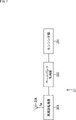
- the master station 11 a shown in FIG. 4 includes a signal processing section 101 , a high frequency processing section 102 and an antenna 103 .
- the antenna 103 of the master station 11a is installed in seawater (in a liquid) and used for communication with the slave station 21, the relay station 15, and other master stations 11 installed in the seawater.
- the antenna 103 which will be described in detail later, is a circularly polarized antenna.
- a signal from the slave station 21 is received by the antenna 103 of the master station 11 and supplied to the high frequency processing unit 102 .
- the high-frequency processing unit 102 is configured to process the received signal as described with reference to FIG. 8, or to process the received signal and the transmitted signal as described with reference to FIG. be.
- the operating frequency fw of the high frequency processing unit 102 is set to, for example, 1 MHz or less.
- a signal processed by the high-frequency processing unit 102 is supplied to the signal processing unit 101 .
- the signal processing unit 101 temporarily stores the signal processed by the high-frequency processing unit 102, and processes the received signal for transmission.
- the configuration of the master station 11a shown in FIG. 4 can also be applied as the configuration of the relay station 15.
- antenna 103 has a function of receiving a signal from slave station 21 and a function of transmitting a signal to master station 11 or another relay station 15. have.
- the high-frequency processing unit 102 and the signal processing unit 101 have functions of amplifying and transmitting the received signal.
- FIG. 5 is a diagram showing another configuration example of the master station 11.
- the master station 11b shown in FIG. 5 is configured by adding a high-frequency processor 104 and an antenna 105 to the master station 11a shown in FIG.
- Antenna 105 is installed in the air and used to communicate with communication stations 12 and 13 installed on land, satellites 14 installed in vacuum, and the like.
- a signal from the communication station 13 is received by the antenna 105 of the master station 11 and supplied to the high frequency processing section 104 .
- the high-frequency processing unit 104 is also supplied with a signal processed by the signal processing unit 101 and, for example, a signal to be transmitted to the communication station 13 .
- the high frequency processing unit 104 processes received signals or signals to be transmitted.
- the operating frequency fg of the high frequency processing unit 104 is set to a frequency higher than the operating frequency fw of the high frequency processing unit 102, for example.
- the signal processing unit 101 executes processing for converting a signal from the high frequency processing unit 102 that configures the underwater communication system into a signal for the high frequency processing unit 104 that configures the air communication system. That is, the signal processing unit 101 performs processing for bridging an underwater communication system and a land communication system, for example, processing such as frequency conversion.
- the signal processing unit 101 When a signal is transmitted from the master station 11 to the slave station 21, for example, when an instruction is transmitted from the communication station 13 to the slave station 21 via the master station 11, the signal processing unit 101 , to convert the signal from the high-frequency processing unit 104 into a signal to be sent to the high-frequency processing unit 102 .
- the configuration of the master station 11b shown in FIG. 5 can also be applied as the configuration of the relay station 15.
- antenna 103 has a function of receiving a signal from slave station 21 and a function of transmitting a signal to master station 11 or another relay station 15. have.
- the antenna 105 may have the function of transmitting a signal to the master station 11 or another relay station 15 .
- the high frequency processing unit 102 and the signal processing unit 101 have the function of amplifying and transmitting the received signal.
- the high-frequency processing unit 102 and the signal processing unit 101 may have a function of amplifying the received signal
- the signal processing unit 101 and the high-frequency processing unit 104 may have a function of transmitting the amplified signal.
- FIG. 6 is a diagram showing still another configuration example of the master station 11. As shown in FIG. As described with reference to FIG. 1, when the master station 11 communicates with the communication station 12, the communication station 13, and the satellite 14, the master station 11, as shown in FIG. It is configured to have an antenna and a high-frequency processing unit that match the requirements.
- the master station 11c shown in FIG. 6 includes high frequency processing units 104-1 to 104-3 and antennas 105-1 to 105-3.
- the high-frequency processing unit 104-1 and the antenna 105-1 operate, for example, at the operating frequency fga to receive signals from the communication station 12 and transmit signals to the communication station 12.
- the high-frequency processing unit 104-2 and the antenna 105-2 operate, for example, at the operating frequency fgb, receive signals from the communication station 13, and transmit signals to the communication station 13.
- FIG. High-frequency processor 104-3 and antenna 105-3 operate, for example, at operating frequency fgc to receive signals from satellite 14 and transmit signals to satellite 14.
- FIG. 7 is a diagram showing a configuration example of the child station 21.
- the slave station 21 includes a sensing section 201 , a baseband processing section 202 , a high frequency processing section 203 and an antenna 204 .
- the slave station 21 can be a mobile station such as an underwater drone or robot placed underwater.
- the slave station 21 has a configuration in which the sensing unit 201 includes, for example, sensors for observing water temperature, tidal currents, image sensors, and the like, and can be installed at a specific position.
- the data sensed by the sensing unit 201 is supplied to the baseband processing unit 202.
- the baseband processing unit 202 uses the supplied data as a baseband signal, performs necessary processing on the baseband signal, and supplies the baseband signal to the high-frequency processing unit 203 .
- the high-frequency processing unit 203 operates, for example, at the operating frequency fw, converts the frequency into a signal of the frequency fw, and transmits the signal from the antenna 204 to the master station 11 .
- the high-frequency processing unit 203 is configured to process the received signal as described with reference to FIG. 8, or to process the received signal and the transmitted signal as described with reference to FIG. be.
- the operating frequency fw of the high frequency processing unit 203 is set to, for example, 1 MHz or less.
- the slave station 21 can be configured to transmit and receive data to and from the master station 11, or can be configured to transmit data to the master station 11.
- the antenna 204 of the slave station 21 only needs to have a function of being able to connect to the master station 11 so that data can be exchanged.
- the antenna 204 which will be described later in detail, is a circularly polarized antenna or a linearly polarized antenna. Transmission of the signal from the child station 21 may be intermittent transmission.
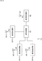
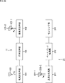
- the upper diagram in FIG. 8 is a diagram showing a configuration example of the high-frequency processing unit 102a in the first embodiment of the master stations 11a to 11c shown in FIGS.
- the lower diagram of FIG. 8 is a diagram showing a configuration example of the high-frequency processing unit 203a in the first embodiment of the child station 21 shown in FIG.
- the high-frequency processing unit 102a and the high-frequency processing unit 203a shown in FIG. 8 are configured such that the master station 11 receives a signal from the slave station 21, and is a configuration example in which the slave station 21 performs only one-way uplink communication. is.
- the high-frequency processing section 102 a is configured to include a matching section 121 , a high-frequency amplification section 122 and a demodulation section 123 .
- the high frequency processing section 203 a is configured to include a modulation section 221 , a high frequency amplification section 222 and a matching section 223 .
- Data resulting from sensing by the sensing unit 201 (FIG. 7) of the slave station 21 is processed by the baseband processing unit 202 (FIG. 7) and supplied to the modulation unit 221 of the high frequency processing unit 203a.
- the modulation section 221 modulates the supplied baseband signal by a predetermined modulation method, and supplies the modulated signal to the high frequency amplification section 222 .
- the modulation unit 221 performs processing such as converting a baseband signal of a digital signal into an analog RF signal, for example.
- the high-frequency amplification section 222 is composed of, for example, a PA (Power Amplifier), amplifies the supplied signal, and supplies it to the matching section 223 .
- PA Power Amplifier
- the matching section 223 executes processing for matching the impedance of the stage preceding the matching section 223 and the impedance of the antenna 204 .
- the amplified signal is supplied to the antenna 204 via the matching section 223 and radiated (transmitted) from the antenna 204 .
- a signal from the antenna 204 is received by the antenna 103 of the master station 11 .
- a signal received by the antenna 103 is supplied to the matching section 121 of the high frequency processing section 102a.
- the matching unit 121 performs processing for matching the impedance of the antenna 103 and the impedance of the stage subsequent to the matching unit 121 .
- a signal received by the antenna 103 is supplied to the high frequency amplification section 122 via the matching section 121 .
- the high-frequency amplification section 122 is composed of, for example, an LNA (Low Noise Amplifier), amplifies the supplied signal, and supplies it to the demodulation section 123 .
- the demodulator 123 demodulates the supplied signal with a demodulation scheme corresponding to the modulation scheme of the modulator 221 of the child station 21 .
- the demodulator 123 performs processing such as converting an analog RF signal into a digital baseband signal, for example.
- the signal demodulated by the demodulator 123 is supplied to the signal processor 101 (not shown in FIG. 8).
- FIG. 9 is a diagram showing a configuration example (referred to as a second embodiment) of the high-frequency processing unit 102b and the high-frequency processing unit 203b when communication between the master station 11 and the slave station 21 is bidirectional. be.
- the high-frequency processing unit 104 of the master station 11 and the high-frequency processing unit 203b of the slave station 21 can have the same configuration.
- the configuration of the high-frequency processing unit 102b of the master station 11 will be taken as an example to continue the description.
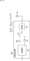
- the high-frequency processing section 102 b for transmission and reception includes a matching section 121 , a transmission/reception switching section 151 , a high-frequency amplification section 122 , a high-frequency amplification section 222 , and a modulation/demodulation section 152 .
- the transmission/reception switching unit 151 When receiving with the antenna 103, the transmission/reception switching unit 151 is connected to the high frequency amplifier 122 side, and the modulation/demodulation unit 152 executes demodulation processing. When transmission is performed by the antenna 103, the transmission/reception switching unit 151 is connected to the high frequency amplifier 222 side, and the modem unit 152 executes modulation processing.
- the antenna 103 side becomes a low impedance system.
- the side of the matching section 121 different from the side to which the antenna 103 is connected (the left side in the drawing) is generally designed with an impedance of about 50 ⁇ .
- the antenna included in the communication device used for land wireless has the role of impedance conversion between the impedance of the feeding circuit and the radiation impedance of the vacuum.
- the impedance on the feeder circuit side is generally designed to be about 50 ⁇ .
- the vacuum radiation impedance is designed to be approximately 377 ⁇ .
- the reason why the antenna 103 side becomes a low impedance system is that the radiation impedance in water is about 42 ⁇ , which is about 1/9 of the radiation impedance in a vacuum.
- the input impedance of the antenna 103 installed in water is also 1/9 or less of that in the air (in a vacuum). If an antenna that operates at 50 ⁇ on land is used in pure water, it can be assumed to operate at about 5.6 ⁇ , and in seawater, it can be assumed to operate at an impedance lower than 5.6 ⁇ .
- the matching section 121 included in the high-frequency processing section 102b included in the master station 11 is designed to have the same design as the matching section included in the communication device used on land, the impedance conversion ratio increases in the matching in the matching section 121. , the band may be narrowed. Also, matching loss may increase the loss.
- the antenna 103 may be designed to have a high impedance input so as to have a value close to the impedance of a general feeding circuit, and have a structure that facilitates matching with the 50 ⁇ system feeding circuit.
- the antenna 103 for high impedance input the loss can be reduced and the bandwidth can be widened.
- the matching section 121 can be configured simply by connecting wires. Become.
- the impedance on the feeder circuit side may be designed to match the impedance of the antenna 103 installed underwater.
- the antenna 103 may be designed as a low-impedance system
- the feed circuit side may be designed as a low-impedance system.
- the matching section 121 can be configured simply by connecting wires. Become.
- the power supply circuit side is a low impedance system, it can be realized by designing the high frequency amplifier section 122 and the high frequency amplifier section 222 using a low impedance input/output device of 10 ⁇ or less.
- the high-frequency amplifier 122 and the high-frequency amplifier 222 may be configured using transistors as shown in FIG. 11 to form a low-impedance power supply circuit.
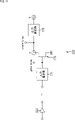
- FIG. 11 is a diagram showing an example configuration of the high-frequency amplifier 222. As shown in FIG.
- the high frequency amplifier section 222 includes an input matching section 171 , a FET (Field Effect Transistor) 172 and an output matching section 173 .
- One end of the input matching section 171 is connected to the modulation/demodulation section 152 (FIG. 9), and the other end is connected to the gate of the FET 172 .
- the drain of the FET 172 is connected to one end a of the output matching section 173 .
- the other end b of the output matching section 173 is connected to the antenna 103 via the transmission/reception switching section 151 (FIG. 9).
- the input matching section 171 matches the impedance of the modulation/demodulation section 152 (FIG. 9) and the input impedance of the FET 172 .
- the output matching unit 173 matches the output impedance of the FET 172 and the impedance of the antenna 103 (FIG. 9).
- the output matching section 173 matches the impedance between 5 ⁇ and the FET 172 .
- the output impedance of the FET 172 is designed to be as close as possible to 5 ⁇ .
- the output impedance of the FET 172 can be lowered, for example, by increasing the number of parallel FETs 172 .
- the impedance of the high frequency amplifier 122 can also be reduced.
- the high-frequency amplifier 122 and the high-frequency amplifier 222 may employ a linear system (classes A, B, AB, C) or a switching system (classes D, E, F, etc.). .
- the antenna 103 of the master station 11 is a circularly polarized antenna. Although the antenna 103 of the master station 11 can be a linearly polarized antenna, communication with the slave station 21 can be performed more reliably by using a circularly polarized antenna.
- FIG. 12 is a diagram simulating the antenna directions of the antenna 103 of the master station 11 and the antenna 204 of the slave station 21 .
- the horizontal direction is the x-axis direction
- the depth direction is the y-axis direction
- the vertical direction is the z-axis direction.
- the antenna 103 of the master station 11 and the antenna 204 of the slave station 21 are linearly polarized antennas in the x direction. Since the master station 11 and the slave station 21 are installed in seawater, there is a possibility that the positional relationship between the antenna 103 of the master station 11 and the antenna 204 of the slave station 21 cannot be kept constant due to the influence of waves. . For example, as shown in FIG. 12, even if the antenna 103 of the master station 11 faces the x-axis direction, the antennas 204 of the child stations 21-1 to 21-3 face directions other than the x-axis direction. It may be suitable.
- the results shown in the lower diagram of FIG. 13 are obtained.
- the plotting range is x, y: 0 to 20 m.
- each graph shown in the lower diagram of FIG. 13 represents the distance (0 to 20 m) in the x-axis direction
- the vertical axis represents the distance (0 to 20 m) in the y-axis direction.
- the electric field intensity Ex of the x component is stronger as the distance from the antenna 103 is shorter (near 0 m), but is weaker as the distance from the antenna 103 is longer.
- a region wx surrounded by a line in the figure is a region where the electric field intensity Ex is particularly weak.
- the electric field strength Ey of the y component is stronger as the distance from the antenna 103 is shorter (near 0 m), but becomes weaker as the distance from the antenna 103 increases.
- a region wy surrounded by a line in the figure is a region where the electric field intensity Ey is particularly weak.
- the electric field intensity Ez of the z component is strong when the distance from the antenna 103 is short (near 0 m), but when the distance from the antenna 103 increases, there is a region wz where the electric field intensity Ez is particularly weak.
- the electric field strength Ez of the z component is weak overall, and there is a high possibility that sufficient reception strength cannot be obtained in the z component.
- the electric field intensity Ex of the x component and the electric field intensity Ey of the y component include regions wx and wy in which the intensity is partially weak. For example, when the polarized wave of the antenna 204 of the slave station 21 is located in the area wx, reception is possible by receiving the y component.
- FIG. FIG. 14 is a diagram that simulates the antenna directions of the antenna 103 of the master station 11 and the antenna 204 of the slave station 21.
- Both the antenna 103 of the master station 11 and the antenna 204 of the slave station 21 are circularly polarized antennas. It is assumed that the antenna 103 of the master station 11 is fixed with circularly polarized waves in the x and y planes.
- the results shown in the lower diagram of FIG. 15 are obtained.
- the plotting range is x, y: 0 to 20 m.
- the electric field intensity Ex of the x component is stronger as the distance from the antenna 103 is shorter (near 0 m), but is weaker as the distance from the antenna 103 is longer. Although this is the same as the case of the linearly polarized antenna, it can be seen that there is no area wx and the electric field intensity Ex is good over the entire area, which is different from the case of the linearly polarized antenna.
- both the x component and the y component of the electric field can be received in any direction.
- the antenna 103 of the master station 11 is configured with a circularly polarized antenna.
- the antenna 103 of the master station 11 a circularly polarized antenna
- the x component and the y component can be received in any direction.
- the z component will not be improved. Signal strength may weaken.
- the antenna 204 of the slave station 21 can be improved by using circular polarization instead of single linear polarization.
- the antenna 204 of the slave station 21 is a linearly polarized antenna, it can be improved by adopting a diversity configuration.
- the antenna 204 of the slave station 21 can also be improved by using a circularly polarized antenna and a diversity configuration.
- the antenna 103 of the master station 11 can also be a circularly polarized antenna and have a diversity configuration. stable reception.
- the antenna 103 of the master station 11 and/or the antenna 204 of the slave station 21 are circularly polarized antennas and have a diversity configuration, thereby achieving a configuration that enables more stable reception.
- LHC left-handed component
- RHC right-handed component
- the direct wave propagating through water reaches the master station 11 with the same polarization, whereas the lateral wave propagating through the air (on the surface of the sea) has the opposite polarization. It reaches the master station 11. As described with reference to FIG. 3, the lateral wave reaches farther than the direct wave. By the way, the left-handed rotation component (LHC) by the lateral wave becomes stronger.
- LHC left-handed rotation component
- the antenna 103 of the master station 11 is a circularly polarized antenna or a circularly polarized diversity antenna.
- the antenna 204 of the slave station 21 is a linearly polarized diversity antenna, a circularly polarized antenna, or a circularly polarized diversity antenna.
- the antenna 204 of the slave station 21 is used for transmitting data to and receiving data from the master station 11 or transmitting data to the master station 11 .
- the antenna 204 may be a linearly polarized diversity antenna or a circularly polarized antenna. or a circular polarization diversity configuration.
- a linearly polarized wave diversity configuration it may be a two-axis polarized wave diversity configuration or a three-axis polarized wave diversity configuration.
- FIG. 16 shows a configuration example of the parent station 11 and a configuration example of the child station 21 in the case of diversity configuration.
- the master station 11 has antennas 103-1 and 103-2 in the high-frequency processing section 102 on the side that communicates with the slave station 21.
- the slave station 21 has antennas 204-1 and 204-2 in the high-frequency processing section 203 on the side that communicates with the master station 11.
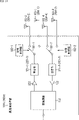
- FIG. 17 is a diagram showing a configuration example of the high-frequency processing unit 102c (referred to as the third embodiment) of the master station 11. As shown in FIG. A high-frequency processing unit 102c shown in FIG. 17 is configured by adding a polarization switching unit 181 and a switching control unit 182 to the high-frequency processing unit 102c shown in FIG.
- the antennas 103-1 and 103-2 are circularly polarized antennas, but are configured to transmit and receive different polarized waves.
- switching control section 182 When receiving a signal, switching control section 182 compares the power of the signal received by antenna 103-1 with the power of the signal received by antenna 103-2. , the polarization switching unit 181 is switched so that the .
- the switching control section 182 selects a polarized wave with higher power at the time of reception, and switches the polarization switching section 181 to the antenna 103-1 or antenna 103-2 of the selected polarized wave.
- the configuration of the high-frequency processing unit 102c shown in FIG. 17 can also be applied to the configuration of the high-frequency processing unit 203c of the slave station 21.
- the high-frequency processing unit 203c shown in FIG. 17 includes antennas 204-1 and 204-2.
- the antennas 204-1 and 204-2 are circularly polarized antennas, and are polarization diversity antennas configured to transmit and receive different polarized waves.
- the antennas 204-1 and 204-2 are linearly polarized antennas, and are polarization diversity antennas configured to transmit and receive polarized waves orthogonal to each other.
- signals When signals are transmitted from antennas 204-1 and 204-2, signals may be transmitted from both antennas 204 at the same timing, or the same signal may be transmitted with different polarizations at different times. You can do so.
- FIG. 18 is a diagram showing a configuration example of the high-frequency processing unit 102d of the master station 11 in the fourth embodiment.
- the high-frequency processing unit 102d shown in FIG. 18 differs from the high-frequency processing unit 102d shown in FIG. 17 in that it has a transmitting antenna and a receiving antenna.
- the high-frequency processing unit 102d shown in FIG. 18 includes antennas 103-1 and 103-2 as diversity antennas for transmission, and antennas 103-3 and 103-4 as diversity antennas for reception.
- the antennas 103-1 to 103-4 are circular polarized antennas.
- antennas 103-1 and 103-2 are linear detection antennas
- antennas 103-3 and 103-4 are circular detection antennas.
- the antenna 103 may be an antenna with different polarization.
- Antenna 103-1 and antenna 103-2 are connected to matching section 121-1 via polarization switching section 181-1.
- Antenna 103-3 and antenna 103-4 are connected to matching section 121-2 via polarization switching section 181-2.
- switching control section 182-1 selects a polarized wave with higher power at the time of reception, and switches polarization switching section 181-1 to antenna 103-1 or antenna 103-2 of the selected polarized wave. switch.
- switching control section 182-2 When receiving a signal, switching control section 182-2 compares the power of the signal received by antenna 103-3 and the power of the signal received by antenna 103-4, and the signal with the higher power is matched. The polarization switching section 181-2 is switched so that the signal is supplied to the section 121-2.
- High-frequency processing section 203d shown in FIG. 18 includes antennas 204-1 and 204-2 as diversity antennas for transmission, and antennas 204-3 and 204-4 as diversity antennas for reception.
- the antennas 204-1 and 204-2 are connected to the matching section 223-1 via the polarization switching section 181-1.
- Antenna 204-3 and antenna 204-4 are connected to matching section 223-2 via polarization switching section 181-2.
- switching control section 182-1 selects a polarized wave with higher power at the time of reception, and switches polarization switching section 181-1 to antenna 204-1 or antenna 204-2 of the selected polarized wave. switch.
- switching control section 182-2 When receiving a signal, switching control section 182-2 compares the power of the signal received by antenna 204-3 and the power of the signal received by antenna 204-4, and the signal with the higher power is matched. The polarization switching section 181-2 is switched so that the signal is supplied to the section 121-2.
- the antennas 204-1 and 204-2 are circularly polarized antennas and are polarization diversity antennas configured to transmit different polarized waves.
- the antennas 204-3 and 204-4 are circularly polarized antennas and are polarization diversity antennas configured to receive different polarized waves.
- the antennas 204-1 and 204-2 are linearly polarized antennas and are polarization diversity antennas configured to transmit mutually orthogonally polarized waves.
- the antennas 204-3 and 204-4 are linearly polarized antennas, and are polarization diversity antennas configured to receive polarized waves orthogonal to each other.
- antennas 204-1 and 204-2 are linearly polarized antennas
- antennas 204-3 and 204-4 are circularly polarized antennas, and so on. may be composed of antennas with different polarized waves.
- signals When signals are transmitted from antennas 204-1 and 204-2, signals may be transmitted from both antennas 204 at the same timing, or the same signal may be transmitted with different polarizations at different times. You can do so.
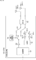
- FIG. 19 is a diagram showing a configuration example of the high-frequency processing unit 102e of the master station 11 according to the fifth embodiment.
- the high-frequency processing unit 102e shown in FIG. 19 matches the signals received by the antennas 103-1 and 103-2 with a combining unit 192 that combines the signals received by the antennas 103-1 and 103-2.
- a matching unit 233 is provided.
- the signals received by the antennas 103-1 and 103-2 are supplied to the transmission/reception switching section 231 via the matching section 233. During signal reception, the transmission/reception switching unit 231 is switched to the phase shifter 191 side. A signal received at antenna 103-1 is supplied to phase shifter 191-1, and a signal received at antenna 103-2 is supplied to phase shifter 191-2.
- the signal supplied to the phase shifter 191-1 is adjusted in phase amount and supplied to the high frequency amplifier 122-1.
- the signal supplied to the phase shifter 191-2 is adjusted in phase amount and supplied to the high frequency amplifier 122-2.
- Phase shifters 191-1 and 191-2 match the phases of the signal received by antenna 103-1 and the signal received by antenna 103-2.
- the high frequency amplifiers 122-1 and 122-2 adjust the gain by amplifying the input signals.
- the signal amplified by the high-frequency amplifier 122-1 and the signal amplified by the high-frequency amplifier 122-2 are supplied to the combiner 192.
- the synthesizer 192 synthesizes the two supplied signals. Through the processing of the high-frequency amplification section 122 and the combining section 192, gain-adjusted combining is performed so as to maximize the S/N ratio.
- the transmission/reception switching unit 231 is switched to the polarization switching unit 181 side.
- switching control section 182 selects a polarized wave with higher power at the time of reception, and switches polarization switching section 181 to antenna 103-1 or antenna 103-2 of the selected polarized wave.
- the high frequency amplifier section 222 amplifies the signal modulated by the modulation/demodulation section 152 according to a predetermined modulation method. The amplified signal is transmitted by the selected antenna 103-1 or antenna 103-2.
- the antennas 103-1 and 103-2 of the master station 11 are circularly polarized antennas.
- the high-frequency processing unit 102e shown in FIG. 19 is configured for polarization diversity of circularly polarized waves.
- the high-frequency processing unit 102e shown in FIG. 19 has a configuration including the high-frequency amplification unit 122, it may be configured without the high-frequency amplification unit 122. That is, it is also possible to adopt an equal gain combining diversity configuration in which only phases are matched.
- the high-frequency processing unit 102e shown in FIG. 19 can also be configured to include a transmitting antenna and a receiving antenna, like the high-frequency processing unit 102e shown in FIG.
- the configuration of the high-frequency processing unit 102e shown in FIG. 19 can also be applied to the configuration of the high-frequency processing unit 203e of the child station 21.
- the signals received by the antennas 204-1 and 204-2 are passed through the matching unit 233 and the transmission/reception switching unit 231 to the phase shifters 191-1 and 191. -2 respectively.
- the phase amounts of the signals supplied to the phase shifters 191-1 and 191-2 are adjusted and supplied to the high frequency amplification sections 122-1 and 122-2, respectively.
- the gain is adjusted by amplifying the signal in each of the high frequency amplification section 122-1 and the high frequency amplification section 122-2.
- the signal amplified by the high frequency amplification section 122-1 and the signal amplified by the high frequency amplification section 122-2 are supplied to the combining section 192 and combined.
- gain-adjusted combining is performed so as to maximize the S/N ratio.
- the transmission/reception switching unit 231 is switched to the polarization switching unit 181 side.
- switching control section 182 selects a polarized wave with higher power at the time of reception, and switches polarization switching section 181 to antenna 204-1 or antenna 204-2 of the selected polarized wave.
- the high frequency amplifier section 222 amplifies the signal modulated by the modulation/demodulation section 152 according to a predetermined modulation method. The amplified signal is transmitted by the selected antenna 204-1 or antenna 204-2.
- the antenna 204 of the slave station 21 is a linearly polarized antenna or a circularly polarized antenna.
- the antennas 204-1 and 204-2 of the slave station 21 may each be a linearly polarized antenna such as a dipole antenna, and the two sets of antennas 204 may be mounted orthogonally.
- the antennas 204-1 and 204-2 of the slave station 21 may be circularly polarized antennas, respectively, and the high-frequency processing unit 203e may be configured with circularly polarized polarization diversity.
- the high-frequency processing unit 203e shown in FIG. 19 has a configuration including the high-frequency amplification unit 122, it may be configured without the high-frequency amplification unit 122. That is, it is also possible to adopt an equal gain combining diversity configuration in which only phases are matched.
- the high-frequency processing unit 203e shown in FIG. 19 can also be configured to include a transmitting antenna and a receiving antenna, like the high-frequency processing unit 203e shown in FIG.
- a circularly polarized microstrip antenna is a planar antenna comprising a dielectric substrate, radiating elements printed on both sides of the substrate, and a ground conductor plate.
- the radiating element of such a microstrip antenna may be circularly polarized by making a notch or the like so as to be used as the above-described circularly polarized antenna 103 .
- a cross dipole antenna can also be used for the circularly polarized antenna 103 of the master station 11, as shown in B of FIG.
- An antenna configured to have a difference in length between the orthogonally intersecting elements 103a and 103b so that the orthogonally polarized waves have a phase difference of 90° may be used as the circularly polarized antenna 103 described above.
- the circularly polarized antenna 103 of the master station 11 is a pair of linearly polarized antennas 103a and 103b, which are orthogonal to each other. can also be an antenna in which The antennas 103a and 103b shown in FIG. 20C are linearly polarized microstrip antennas.
- the signal supplied to the distributor 301 is supplied to the antennas 103a and 103b.
- the signal supplied to the antenna 103b is a signal whose phase difference is shifted by 90° by the phase shifter 302. FIG.
- the configuration of the circularly polarized antenna 103 shown in FIGS. 20A to 20C can also be applied when the antenna 204 of the slave station 21 is a circularly polarized antenna.
- a circularly polarized antenna may have a configuration other than the one exemplified here.
- the power required for the operation of the above-described master station 11 and slave station 21 may be supplied from the solar power generator provided in the master station 11 and slave station 21, for example. can do.
- non-contact power supply can be applied as a method of supplying power to the parent station 11 or the child station 21, non-contact power supply can be applied.
- the system represents an entire device composed of multiple devices.
- the present technology can also take the following configuration.
- a first antenna that connects with a communication network in the liquid;
- a first signal processing unit that processes at least one of a signal received by the first antenna or a signal transmitted by the first antenna, The communication device, wherein the first antenna is a circularly polarized antenna.
- a second antenna that connects to an in-gas communication network;
- the communication device according to (1) above further comprising a second signal processing unit that processes at least one of a signal received by the second antenna and a signal to be transmitted by the second antenna.
- the first antenna receives a signal from another communication device in the liquid;
- the communication device according to (1) wherein the first signal processing unit amplifies the received signal and transmits it to another communication device through the first antenna.
- the first signal processing unit is a matching section that matches the impedance of the first antenna and the impedance in the first signal processing section; an amplifier that amplifies the signal received or transmitted by the first antenna;
- the communication device according to any one of (1) to (7), further comprising: a modulation/demodulation section that modulates or demodulates the signal received or transmitted by the first antenna.
- the communication device wherein the impedance of the first antenna and the impedance in the first signal processing unit are 10 ⁇ or less.
- a communication system including a first communication device and a second communication device,
- the first communication device is a first antenna that connects with the second communication device in liquid; a first signal processing unit that processes a signal from the second communication device received by the first antenna,
- the second communication device is a second antenna that connects with the first communication device in liquid; a second signal processing unit that processes a signal to be transmitted to the first communication device by the second antenna,
- the first antenna is a circularly polarized antenna
- the communication system, wherein the second antenna is a circularly polarized or linearly polarized antenna.
- the communication system according to (11), wherein the second antenna is a polarization diversity antenna including two circularly polarized antennas or two linearly polarized antennas.
- the second communication device forms an ad-hoc network.
- the communication system according to any one of (11) to (14), wherein transmission of the signal from the second communication device to the first communication device is intermittent transmission.
- the first communication device is A third antenna and a third signal processing unit connected to a land communication network or a satellite communication network are provided for each communication network, The communication system according to any one of (11) to (15), wherein the signal from the second communication device is transmitted to the land communication network or the satellite communication network.
- 1 communication system 11 master station, 12, 13 communication station, 14 satellite, 15 relay station, 21 slave station, 31 transmitter, 32 receiver, 101 signal processing unit, 102 high frequency processing unit, 103 antenna, 104 high frequency processing unit , 105 antenna, 121 matching section, 122 high frequency amplifier section, 123 demodulation section, 151 transmission/reception switching section, 152 modulation/demodulation section, 171 input matching section, 172 FET, 173 output matching section, 181 polarization switching section, 182 switching control section, 191 phase shifter, 192 synthesizing section, 201 sensing section, 202 baseband processing section, 203 high frequency processing section, 204 antenna, 221 modulation section, 222 high frequency amplification section, 223 matching section, 231 transmission/reception switching section, 233 matching section, 301 distributor, 302 phase shifter
Landscapes
- Engineering & Computer Science (AREA)
- Computer Networks & Wireless Communication (AREA)
- Signal Processing (AREA)
- Mobile Radio Communication Systems (AREA)
Priority Applications (2)
| Application Number | Priority Date | Filing Date | Title |
|---|---|---|---|
| JP2023529497A JPWO2022264510A1 (https=) | 2021-06-17 | 2022-02-15 | |
| US18/567,798 US20240283547A1 (en) | 2021-06-17 | 2022-02-15 | Communication device and communication system |
Applications Claiming Priority (2)
| Application Number | Priority Date | Filing Date | Title |
|---|---|---|---|
| JP2021100681 | 2021-06-17 | ||
| JP2021-100681 | 2021-06-17 |
Publications (1)
| Publication Number | Publication Date |
|---|---|
| WO2022264510A1 true WO2022264510A1 (ja) | 2022-12-22 |
Family
ID=84526070
Family Applications (1)
| Application Number | Title | Priority Date | Filing Date |
|---|---|---|---|
| PCT/JP2022/005798 Ceased WO2022264510A1 (ja) | 2021-06-17 | 2022-02-15 | 通信装置、通信システム |
Country Status (3)
| Country | Link |
|---|---|
| US (1) | US20240283547A1 (https=) |
| JP (1) | JPWO2022264510A1 (https=) |
| WO (1) | WO2022264510A1 (https=) |
Citations (3)
| Publication number | Priority date | Publication date | Assignee | Title |
|---|---|---|---|---|
| JPH104313A (ja) * | 1996-06-17 | 1998-01-06 | Tohoku Electric Power Co Inc | アンテナ装置 |
| JP2009302963A (ja) * | 2008-06-13 | 2009-12-24 | Rcs:Kk | 磁力波通信装置 |
| JP2012253695A (ja) * | 2011-06-06 | 2012-12-20 | Rcs:Kk | 磁力波伝搬を利用した通信事業 |
Family Cites Families (13)
| Publication number | Priority date | Publication date | Assignee | Title |
|---|---|---|---|---|
| FR2699713B1 (fr) * | 1992-12-17 | 1995-03-24 | Hubert Thomas | Procédé et dispositif de contrôle à distance d'un engin sous marin inhabité. |
| US7236807B1 (en) * | 1999-10-28 | 2007-06-26 | Celletra Ltd. | Cellular base station augmentation |
| SE521761C2 (sv) * | 2000-06-26 | 2003-12-02 | Ericsson Telefon Ab L M | Antennanordning och ett därtill relaterat förfarande |
| US9270387B2 (en) * | 2005-06-15 | 2016-02-23 | Wfs Technologies Ltd. | Mobile device with an underwater communications system and method |
| US8102733B2 (en) * | 2007-03-09 | 2012-01-24 | Lockheed Martin Corporation | Communicating using sonar signals at multiple frequencies |
| US8804461B2 (en) * | 2010-09-13 | 2014-08-12 | Incube Labs, Llc | Self-propelled buoy for monitoring underwater objects |
| WO2013017175A1 (en) * | 2011-08-04 | 2013-02-07 | Telefonaktiebolaget L M Ericsson (Publ) | An outdoor-indoor mimo communication system using multiple repeaters and leaky cables |
| GB201203671D0 (en) * | 2012-03-02 | 2012-04-18 | Go Science Ltd | Communication with an underwater vehicle |
| US9213077B2 (en) * | 2012-07-31 | 2015-12-15 | Adaptive Methods, Inc. | GPS assisted torpedo recovery system |
| KR101488298B1 (ko) * | 2013-11-06 | 2015-01-30 | (주)에어포인트 | 무선 중계 장치 및 시스템과 그 방법 |
| US9979089B2 (en) * | 2016-04-01 | 2018-05-22 | Pulse Finland Oy | Dual polarized antenna apparatus and methods |
| US10447470B2 (en) * | 2017-10-04 | 2019-10-15 | The Boeing Company | Secure and disruption-tolerant communications for unmanned underwater vehicles |
| US20200177221A1 (en) * | 2018-12-04 | 2020-06-04 | The United States Of America As Represented By Secretary Of The Navy | Submerged Maritime Tag Track and Locate Device and System |
-
2022
- 2022-02-15 US US18/567,798 patent/US20240283547A1/en active Pending
- 2022-02-15 JP JP2023529497A patent/JPWO2022264510A1/ja active Pending
- 2022-02-15 WO PCT/JP2022/005798 patent/WO2022264510A1/ja not_active Ceased
Patent Citations (3)
| Publication number | Priority date | Publication date | Assignee | Title |
|---|---|---|---|---|
| JPH104313A (ja) * | 1996-06-17 | 1998-01-06 | Tohoku Electric Power Co Inc | アンテナ装置 |
| JP2009302963A (ja) * | 2008-06-13 | 2009-12-24 | Rcs:Kk | 磁力波通信装置 |
| JP2012253695A (ja) * | 2011-06-06 | 2012-12-20 | Rcs:Kk | 磁力波伝搬を利用した通信事業 |
Also Published As
| Publication number | Publication date |
|---|---|
| US20240283547A1 (en) | 2024-08-22 |
| JPWO2022264510A1 (https=) | 2022-12-22 |
Similar Documents
| Publication | Publication Date | Title |
|---|---|---|
| US11502424B2 (en) | Wireless transceiver having receive antennas and transmit antennas with orthogonal polarizations in a phased array antenna panel | |
| US8089404B2 (en) | Partitioned aperture array antenna | |
| US11264721B2 (en) | Antenna, configuration method of antenna and wireless communication device | |
| US10389041B2 (en) | Phased array antenna panel with enhanced isolation and reduced loss | |
| US11411315B2 (en) | Antenna module and antenna device | |
| CN101207235A (zh) | 移动卫星通信相控阵天线 | |
| US20180090815A1 (en) | Phased Array Antenna Panel Having Quad Split Cavities Dedicated to Vertical-Polarization and Horizontal-Polarization Antenna Probes | |
| US20100099370A1 (en) | Active electronically scanned array antenna for satellite communications | |
| US9692489B1 (en) | Transceiver using novel phased array antenna panel for concurrently transmitting and receiving wireless signals | |
| JPH0964639A (ja) | ダイバーシチ・アンテナ回路 | |
| US20200335867A1 (en) | Dual-polarized retrodirective array and multi-frequency antenna element | |
| US20180090814A1 (en) | Phased Array Antenna Panel Having Cavities with RF Shields for Antenna Probes | |
| US12438279B2 (en) | Base station antenna | |
| WO2009012361A1 (en) | Radio beam forming antenna with electroactive polymer actuator | |
| WO2022264510A1 (ja) | 通信装置、通信システム | |
| US20180090813A1 (en) | Low-Cost and Low-Loss Phased Array Antenna Panel | |
| KR100748337B1 (ko) | 이중편파 다이버시티 능동형 마이크로스트립 배열 안테나 | |
| US9948260B1 (en) | Wireless receiver with reduced number of phase shifters | |
| EP4379953B1 (en) | Circular polarized antenna array module and wireless communication device | |
| KR20010001091A (ko) | 마스트 안테나 시스템 | |
| US20260113087A1 (en) | Systems and methods for transmitting multiple beams from a single antenna aperture | |
| JP2011142413A (ja) | 無線通信システム | |
| CN118073867A (zh) | 一种极化变换器 | |
| WO2009009533A1 (en) | Single input/output mesh antenna with linear array of cross polarity dipole radiating elements |
Legal Events
| Date | Code | Title | Description |
|---|---|---|---|
| 121 | Ep: the epo has been informed by wipo that ep was designated in this application |
Ref document number: 22824510 Country of ref document: EP Kind code of ref document: A1 |
|
| WWE | Wipo information: entry into national phase |
Ref document number: 2023529497 Country of ref document: JP |
|
| WWE | Wipo information: entry into national phase |
Ref document number: 18567798 Country of ref document: US |
|
| NENP | Non-entry into the national phase |
Ref country code: DE |
|
| 122 | Ep: pct application non-entry in european phase |
Ref document number: 22824510 Country of ref document: EP Kind code of ref document: A1 |